bruno p. evangelista (ufmg) alessandro r. silva (ufmg)bruno p. evangelista (ufmg) alessandro r....
TRANSCRIPT
Bruno P. Evangelista (UFMG)
Alessandro R. Silva (UFMG)Revision 2
2
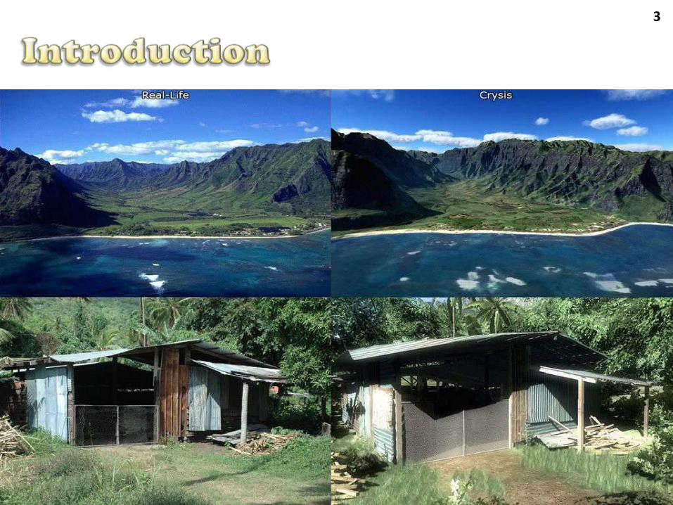
The fast evolution of the programmable graphics hardware (GPUs) are making the games very realistic!
Is it still possible to distinguish between a game scene and a real-life picture?
3
4
The modern GPUs enable us to create many rendering effects
We can use these effects to create very realisticenvironments
Or even non-realistic environments
In this lecture we will discuss and show some effects that are commonly used in games
5
Rendering Pipeline and Shaders (Quick Review)
Shader LanguagesEffects
Per-Pixel IlluminationEnvironment Reflection/RefractionTexturing/Multi-texturingProcedural Texture GenerationSimulation of Detailed Surfaces
Pos-Processing EffectsRadiometryBloomCartoon Rendering
6
For many years, graphics APIs such as DirectX and OpenGL used a fixed rendering pipeline
The process executed within each stage of therendering pipeline was pre-programmed in hardware and cannot be modified
For example: Transformations, lighting and so on...
It was only possible to configure a few parameterson the pipeline
Result: Games with resembling graphics!
7
Meantime...
The cinema industry already had tools capable ofprogramming the rendering of the scenes
RenderMan
Shader language specification created by Pixar in 1988
Nowadays there are some open-source andcommercial implementations
However, those tools were used just for offline rendering! =(
8
Small programs that run into the GPU
Allow the programming of some stages of the rendering pipeline
New things that you can do:
Real world illumination models
Rendering of very detailed surfaces
Pos-processing over the scenes
And we can use everyting in real-time!
9
Shaders that run in different stages of the GPU have different names
Vertex Shader – Vertex Processing Stage
Pixel Shader – Pixel Processing Stage
Geometry Shader – Geometry Processing Stage
10
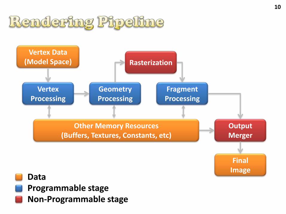
Rasterization
FragmentProcessing
FinalImage
Vertex Data(Model Space)
Other Memory Resources(Buffers, Textures, Constants, etc)
GeometryProcessing
OutputMerger
VertexProcessing
DataProgrammable stageNon-Programmable stage
11
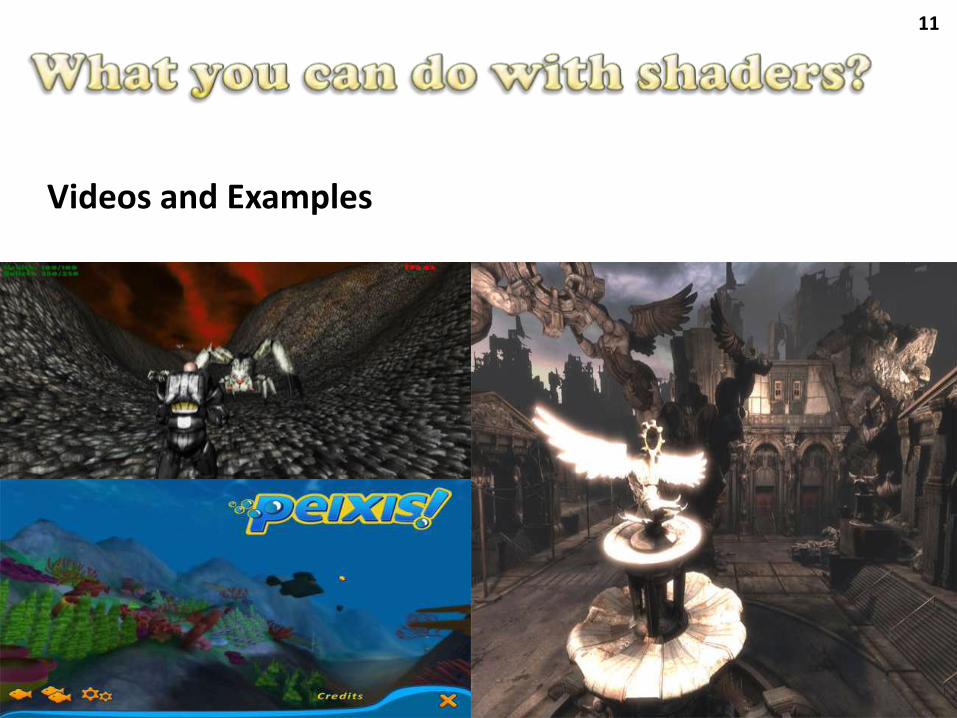
Videos and Examples
12
Offline Rendering
RenderMan – PRMan Pixar/Other implementations
Gelato – nVidia
Real-time Rendering
HLSL (High Level Shading Language) – MicrosoftUsed on DirectX e XNA
GLSL (OpenGL Shading Language) – 3D LabsUsed on OpenGL
Cg (C for Graphics) – nVidiaCan be used on both DirectX and OpenGL
13
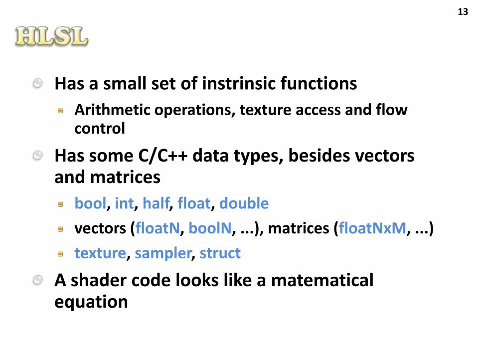
Has a small set of instrinsic functions
Arithmetic operations, texture access and flowcontrol
Has some C/C++ data types, besides vectors and matrices
bool, int, half, float, double
vectors (floatN, boolN, ...), matrices (floatNxM, ...)
texture, sampler, struct
A shader code looks like a matematical equation
14
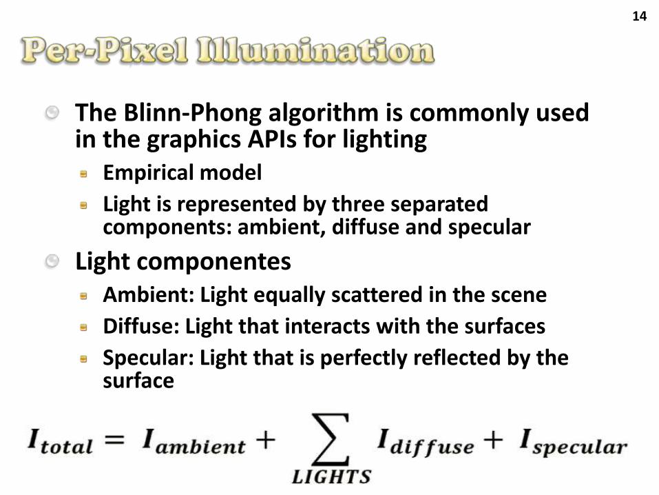
The Blinn-Phong algorithm is commonly used in the graphics APIs for lighting
Empirical model
Light is represented by three separatedcomponents: ambient, diffuse and specular
Light componentesAmbient: Light equally scattered in the scene
Diffuse: Light that interacts with the surfaces
Specular: Light that is perfectly reflected by the surface
15
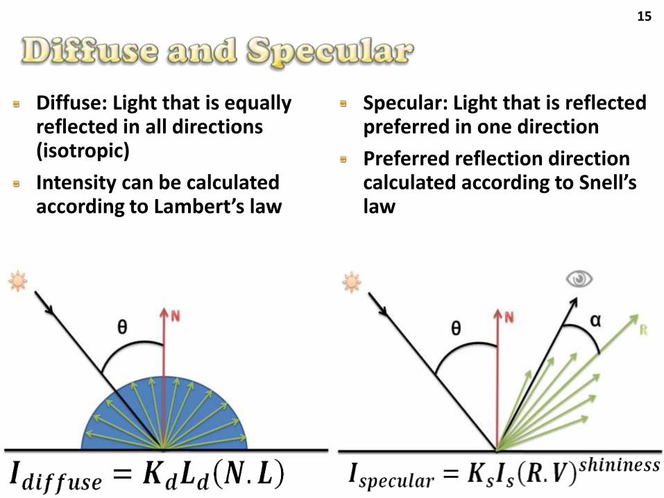
Diffuse: Light that is equallyreflected in all directions(isotropic)
Intensity can be calculatedaccording to Lambert’s law
Specular: Light that is reflectedpreferred in one direction
Preferred reflection directioncalculated according to Snell’s law
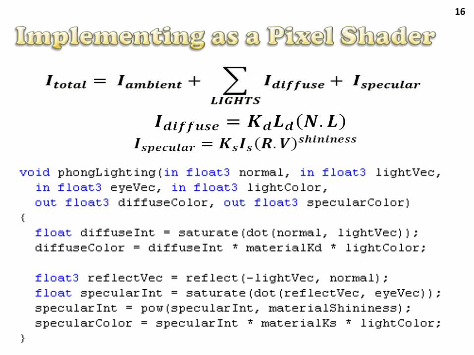
16
17
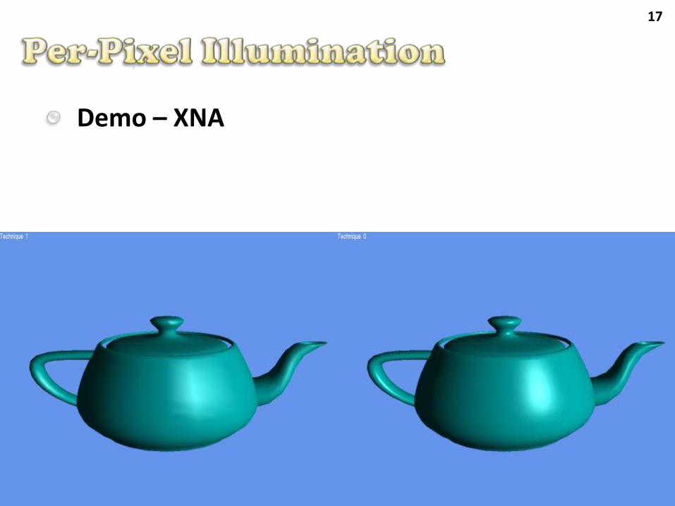
Demo – XNA
18
We can define a range for point and spot lights and use it to attenuate the light intensity
The attenuation determines how fast the light intensity decreases
Attenuation can be constant, linear, quadratic, etc…
Using attenuation the reflect light appears more smooth over the surface
19
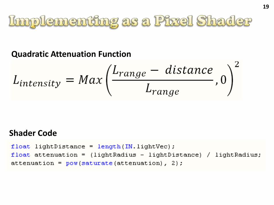
Shader Code
Quadratic Attenuation Function
20
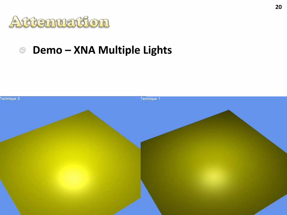
Demo – XNA Multiple Lights
21
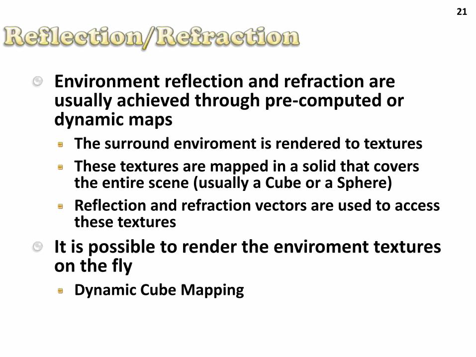
Environment reflection and refraction are usually achieved through pre-computed or dynamic maps
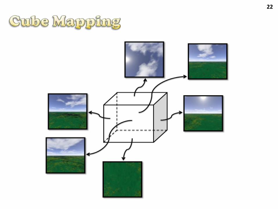
The surround enviroment is rendered to textures
These textures are mapped in a solid that coversthe entire scene (usually a Cube or a Sphere)
Reflection and refraction vectors are used to accessthese textures
It is possible to render the enviroment textures on the fly
Dynamic Cube Mapping
22
23
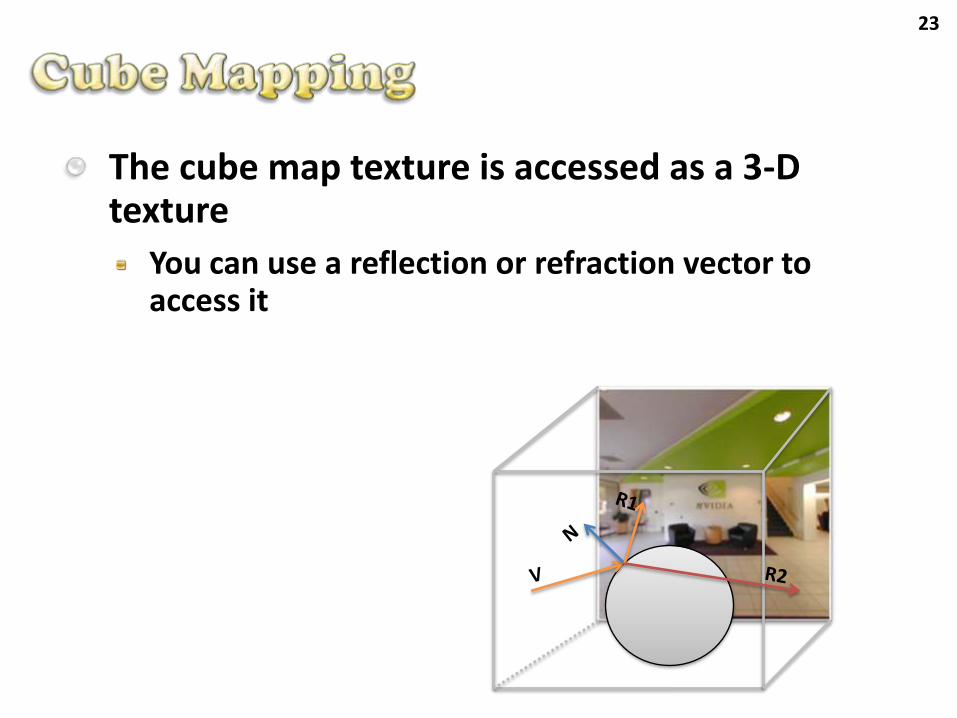
The cube map texture is accessed as a 3-D texture
You can use a reflection or refraction vector to access it
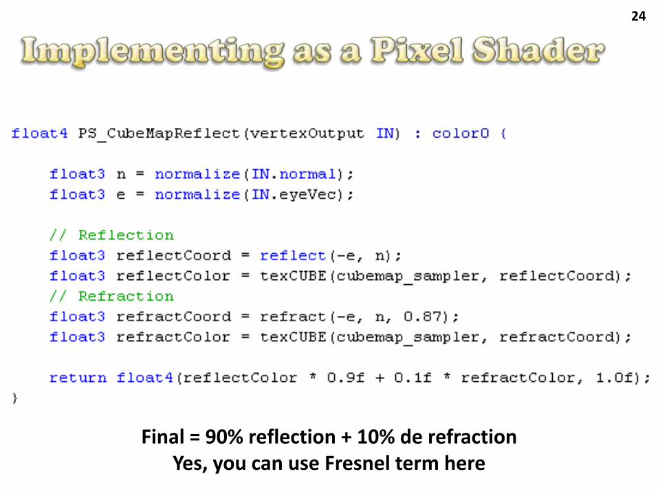
24
Final = 90% reflection + 10% de refractionYes, you can use Fresnel term here
25
Demo – FX Composer
26
Can be seen as a function that maps a coordinate to a color
The function can be implemented either:
From an image (texture access)
From an algorithm (procedural)
27
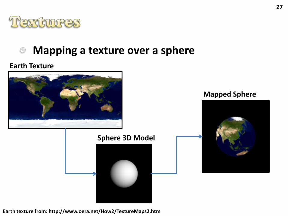
Mapping a texture over a sphere
Earth texture from: http://www.oera.net/How2/TextureMaps2.htm
Earth Texture
Sphere 3D Model
Mapped Sphere
28
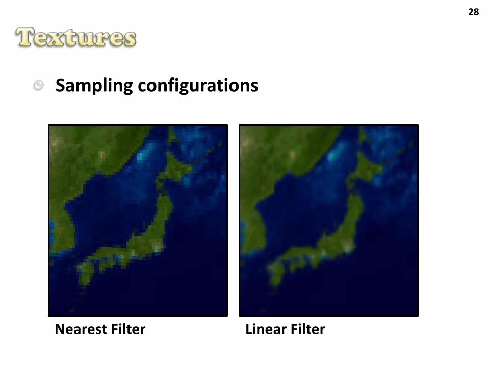
Sampling configurations
Nearest Filter Linear Filter
29
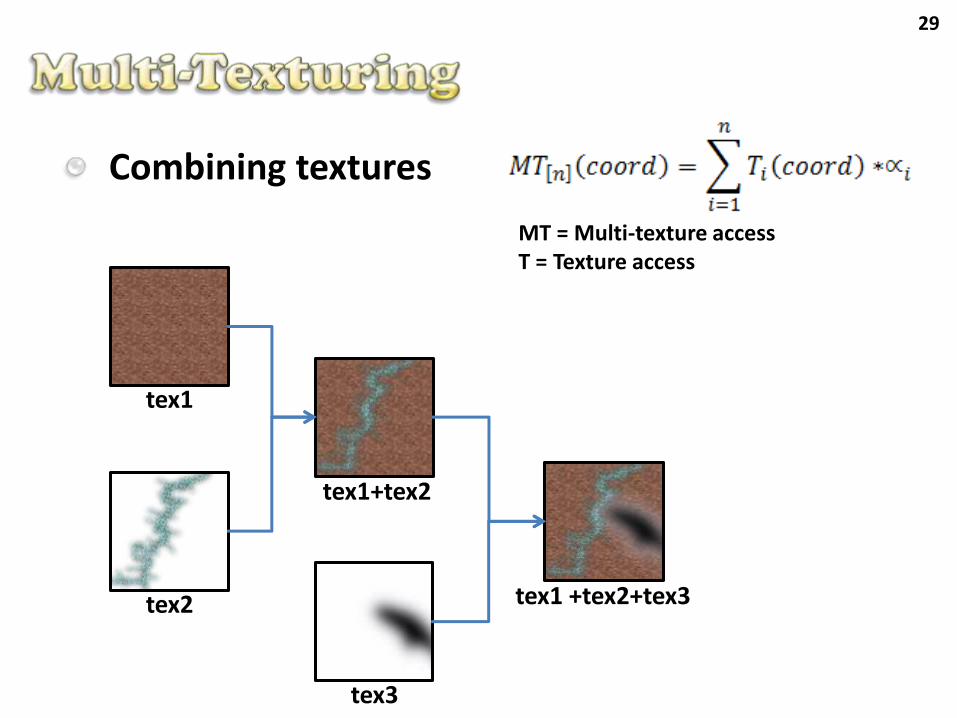
Combining textures
tex1
tex2
tex3
tex1+tex2
tex1 +tex2+tex3
MT = Multi-texture accessT = Texture access
30
Demo – FX Composer
A_GlobalSingle
B_Multitexture
31
Textures that are generated by algorithms
There are some base models that we can use:
Noise (Perlin, 85)
Cellular (Worley, 96)
Analytical functions
Others...
32
Interesting features
Parametric control
Compact representation (you just need to store a few parameters)
Some algorithms are easy to implement
Problems
Aliasing
Control over details
Performance
33
Noise (Perlin, 85)
Tries to model random behavior observed on nature
Desired properties
Statistically invariant to orientation and translation:
Maintains the noise appearance over the space
Limited dynamic range:
Allows the noise to be sampled at different scaleswithout aliasing
34
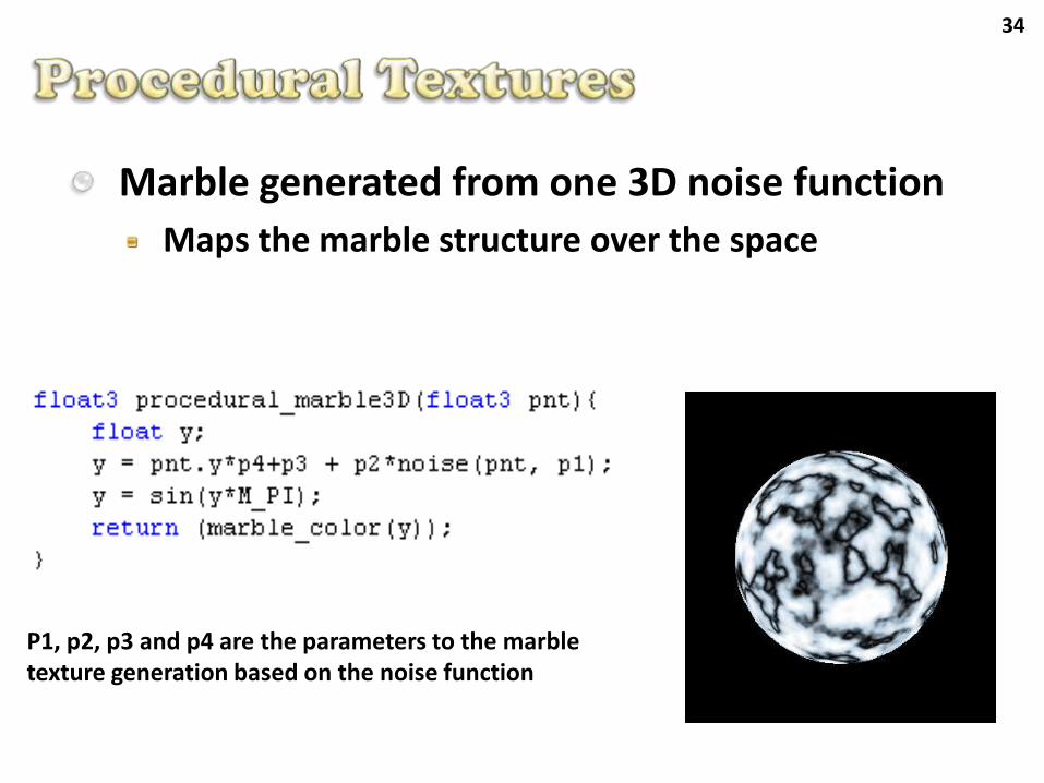
Marble generated from one 3D noise function
Maps the marble structure over the space
P1, p2, p3 and p4 are the parameters to the marble texture generation based on the noise function
35
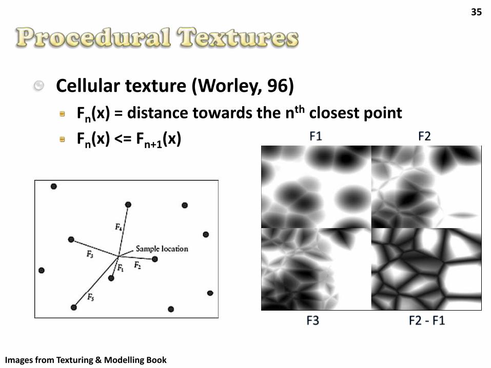
Cellular texture (Worley, 96)
Fn(x) = distance towards the nth closest point
Fn(x) <= Fn+1(x)
Images from Texturing & Modelling Book
36
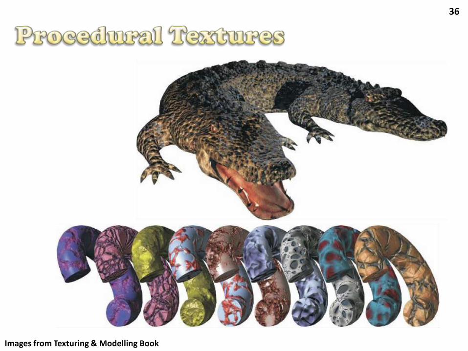
Images from Texturing & Modelling Book
37
Demo – FX Composer
C_ProceduralSquare
D_ProceduralMarble
38
In the real world, objects are often composed of highly detailed surfaces
Mesostructure: small scale details: bumps, roughness, etc...
Microstructure: micro details that are visually indistinguishable but might change how the light is reflected
ProblemsRequire millions of triangles to be computationally represented (boundary representation)
Storage and processing of a big amount of data, unfeasible for real-time rendering
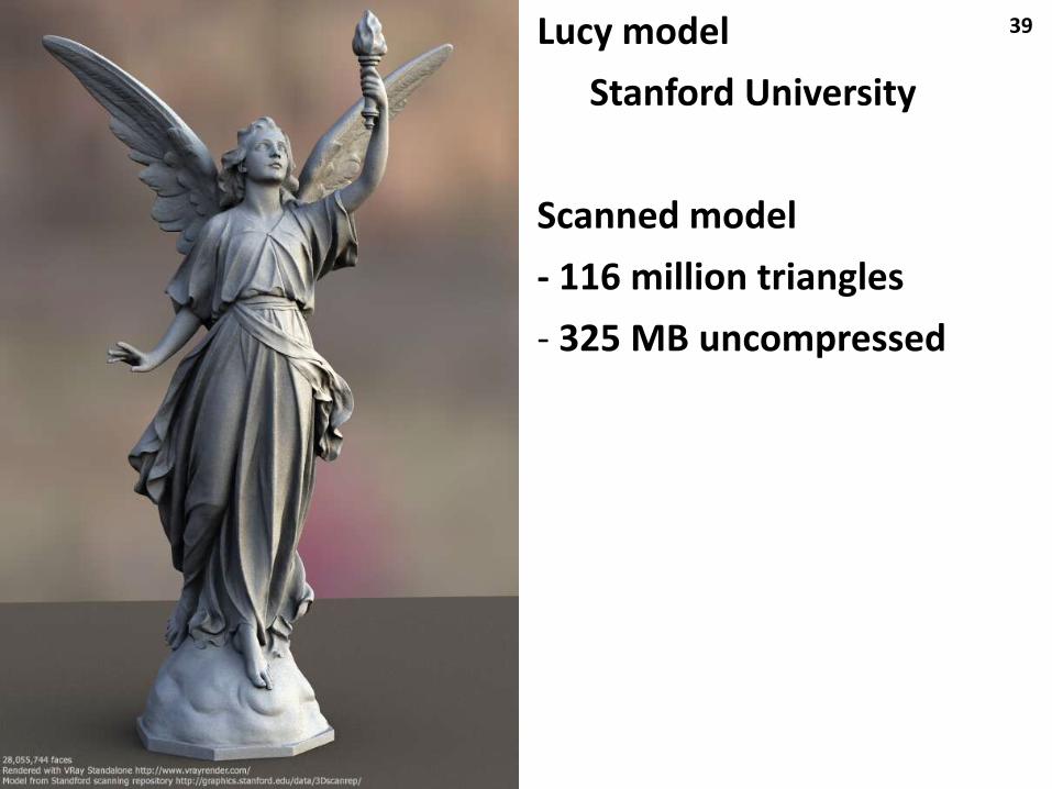
39Lucy model
Stanford University
Scanned model
- 116 million triangles
- 325 MB uncompressed
40
SolutionSimulate the surface details without increasing itssurface complexity
Some well known techniquesBump Mapping
Normal Mapping
Offset Parallax Mapping
Relief Mapping
Parallax Offset Mapping
Cone Step Mapping
41
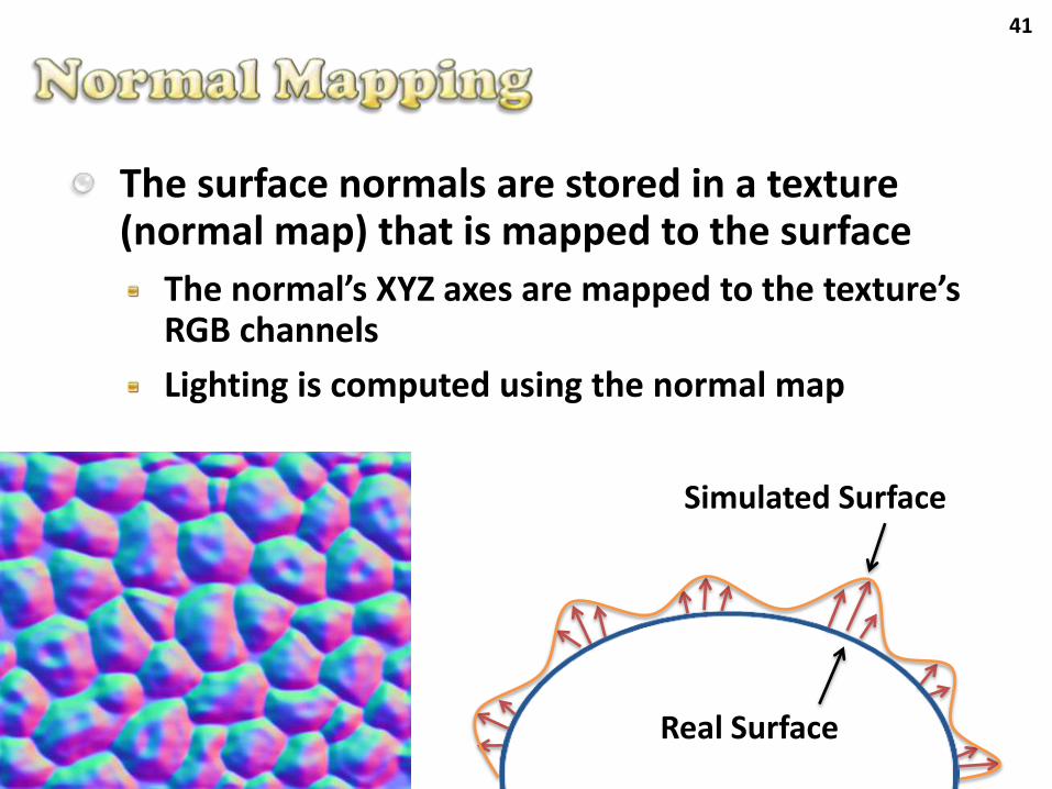
The surface normals are stored in a texture (normal map) that is mapped to the surface
The normal’s XYZ axes are mapped to the texture’s RGB channels
Lighting is computed using the normal map
Simulated Surface
Real Surface
42
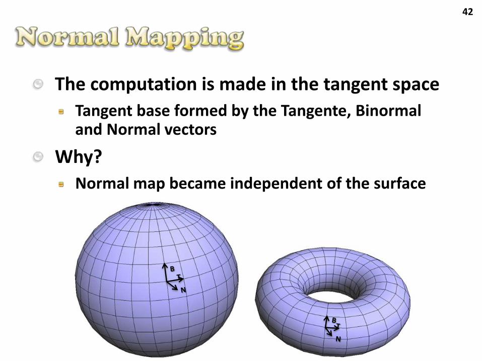
The computation is made in the tangent space
Tangent base formed by the Tangente, Binormaland Normal vectors
Why?
Normal map became independent of the surface
43
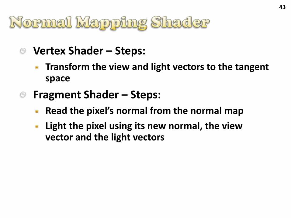
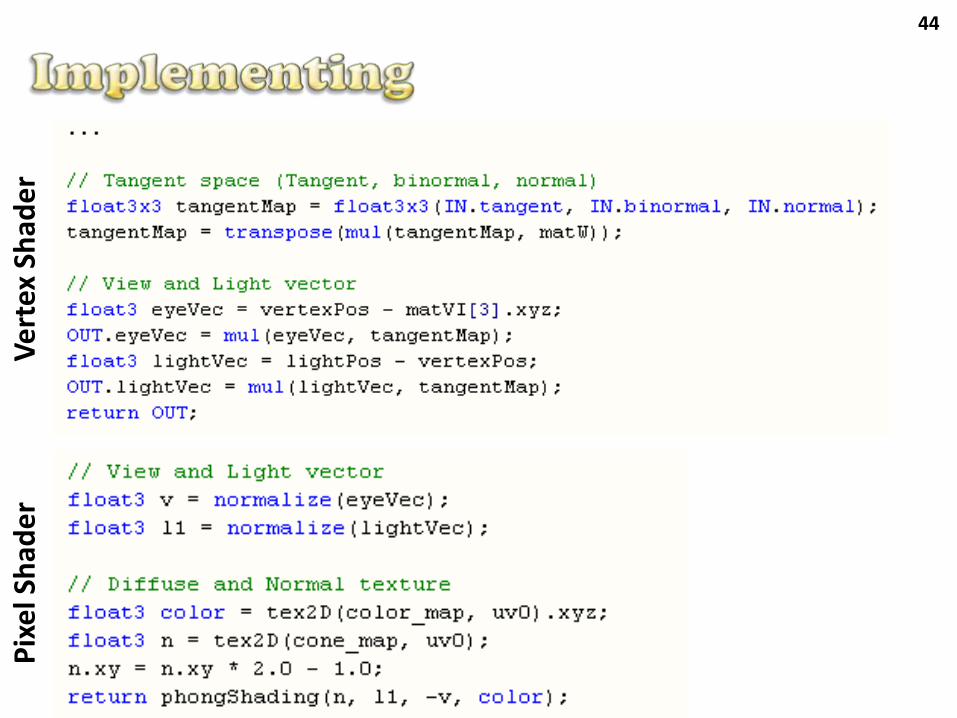
Vertex Shader – Steps:
Transform the view and light vectors to the tangentspace
Fragment Shader – Steps:
Read the pixel’s normal from the normal map
Light the pixel using its new normal, the viewvector and the light vectors
44V
ert
exSh
ade
rP
ixe
lSh
ade
r
45
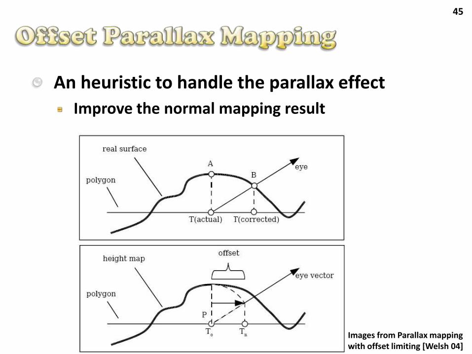
An heuristic to handle the parallax effect
Improve the normal mapping result
Images from Parallax mapping with offset limiting [Welsh 04]
46
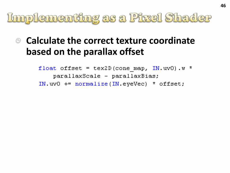
Calculate the correct texture coordinatebased on the parallax offset
47
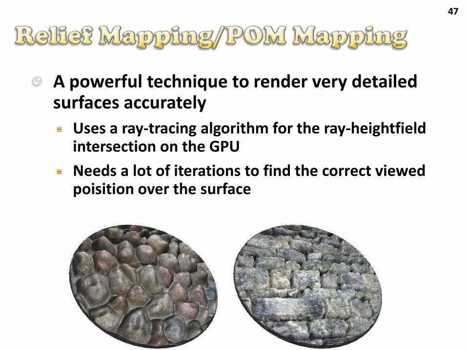
A powerful technique to render very detailed surfaces accurately
Uses a ray-tracing algorithm for the ray-heightfield intersection on the GPU
Needs a lot of iterations to find the correct viewedpoisition over the surface
48
Demo – Detailed Surfaces
49
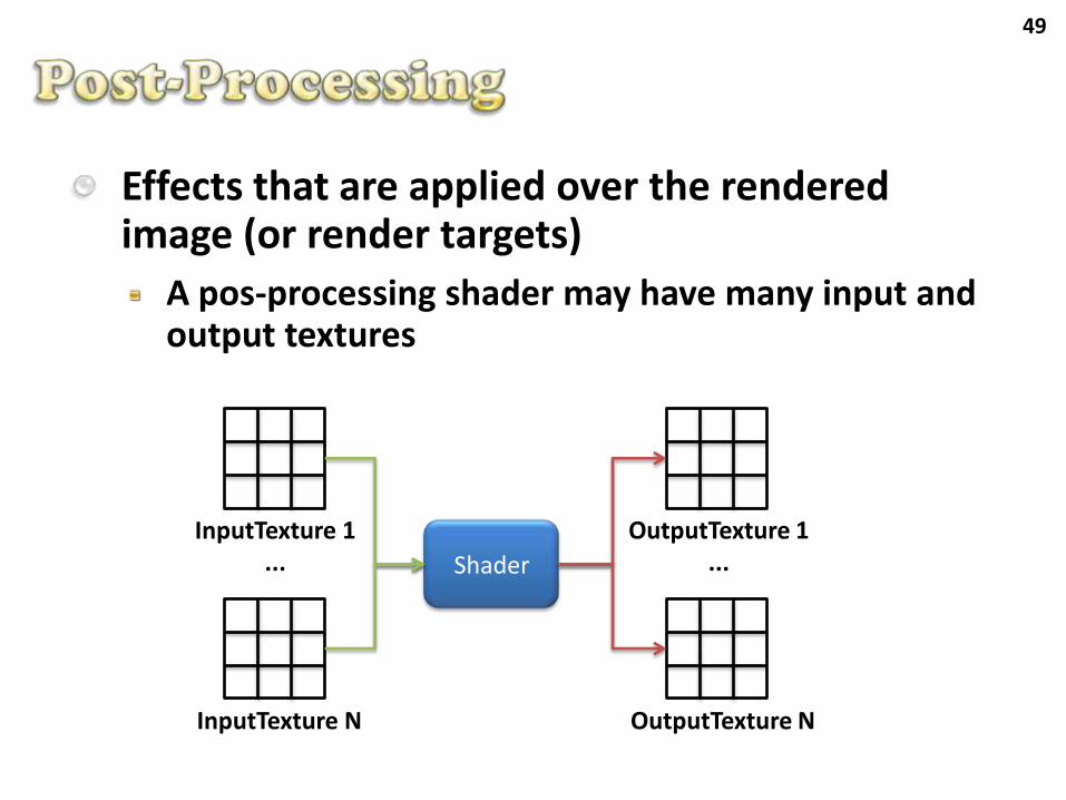
Effects that are applied over the rendered image (or render targets)
A pos-processing shader may have many input andoutput textures
InputTexture 1...
InputTexture N
Shader
OutputTexture 1...
OutputTexture N
50
Digital Image Processing (DIP) algorithms that can be applied
Radiometric transformations
Contrast, brightness, and grayscale conversion
Filters
Blur, edge detection
Image composition
Radial motion blur
51
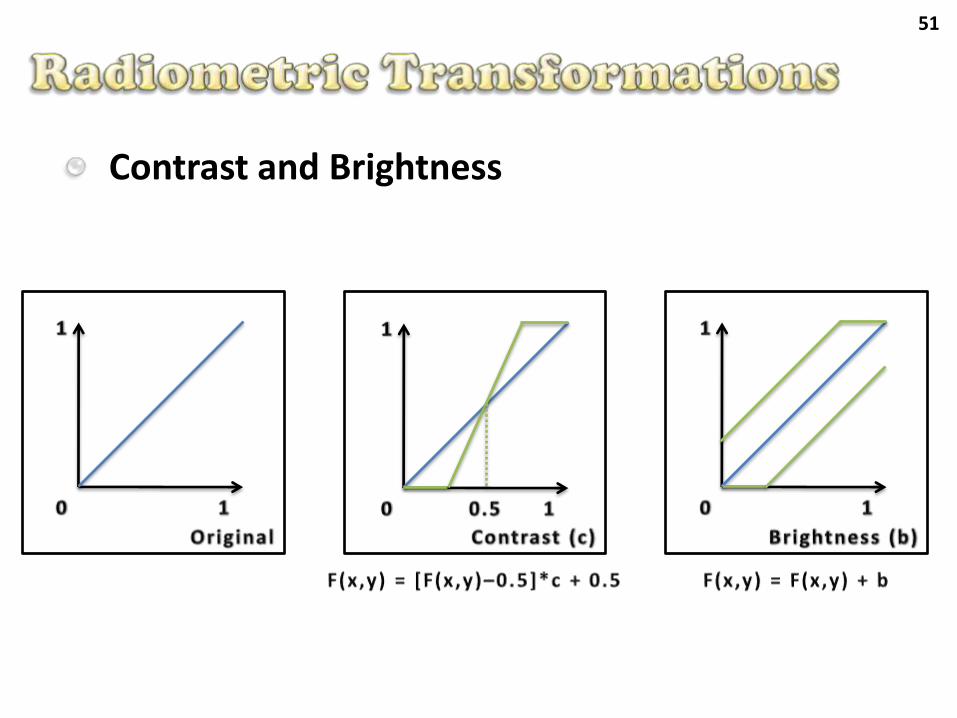
Contrast and Brightness
52
Grayscale conversion
Considering the HSV color space
Gray = (R + G + B)/3
Gray = Max(R, G, B)
Considering the humam perception (YIQ)
The YIQ color space is used in the NTSC signal
Gray = Y = R*0.299 + G*0.587 + B*0.114
53
Demo – FX Composer
E_ppBrilhoContraste
F_ppCinza
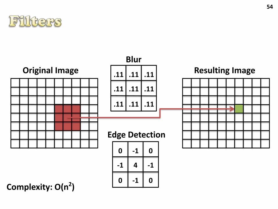
54
Resulting ImageOriginal Image .11 .11 .11
.11 .11
.11 .11 .11
Edge Detection
.11
0 -1 0
-1 -1
0 -1 0
4
Blur
Complexity: O(n2)
55
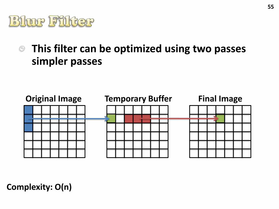
Temporary BufferOriginal Image Final Image
This filter can be optimized using two passes simpler passes
Complexity: O(n)
56
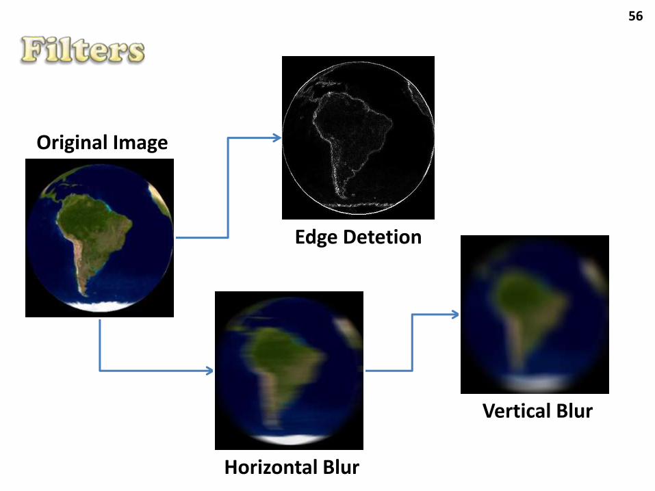
Edge Detetion
Vertical Blur
Horizontal Blur
Original Image
57
Demo – FX Composer
G_ppBlur
H_ppLaplace
58
Composed effects
Some effects are composed by many renderingpasses, where it is necessary to use some auxiliarybuffers (or textures)
In this case, it is necessary to have a rendering flowcontrol (usually implemented in software)
The rendering flow control should save resources(video memory) and manage the render targets
Examples
Bloom, Cartoon Rendering, outros...
59
Try to simulate the light expansion over bright surfaces
Effect perceived in the real world
Lights, Reflections and so on
It is often used in with HDR (High Dynamic Range) techniques
60
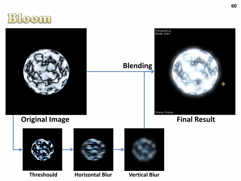
Original Image
Threshould Horizontal Blur Vertical Blur
Final Result
Blending
61
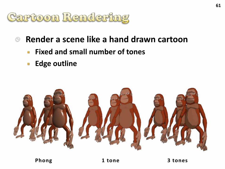
Render a scene like a hand drawn cartoon
Fixed and small number of tones
Edge outline
62
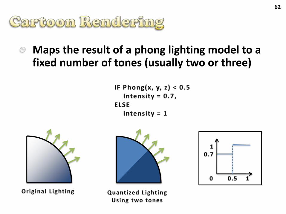
Maps the result of a phong lighting model to a fixed number of tones (usually two or three)
63
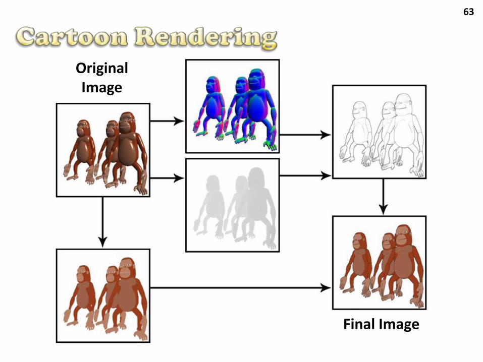
Original Image
Final Image
64
Demo – FX Composer
I_Bloom
Cartoon
65
In this lecture we presented some effects that are used in current commercial games
All these effects are implemented on modern GPUs
In a near future the GPU will be completly programmable and its fixed stages removed
Modern APIs doesn’t support the fixed pipelineanymore (DirectX 10, XNA and OpenGL ME)
Nowadays there are still a few stages that remainsfixed: Rasterization and Output Merger
66
Bruno P. Evangelistawww.BrunoEvangelista.com
Alessandro R. Silvawww.AlessandroSilva.com
“For what will it profit a man if he gains the whole world and forfeits his soul? Or what will a man give in exchange for his soul?” Matthew 16:26