broadband wireless internet forum white paper vofdm ...gram.eng.uci.edu/~ayanoglu/vofdm.pdf ·...
TRANSCRIPT
Broadband Wireless Internet Forum White Paper
VOFDM Broadband Wireless Transmission and Its Advantagesover Single Carrier Modulation
Document Number WP-1_TG-1
Version 1.2
December 15, 2000
NoticeBWIF DISCLAIMS ANY AND ALL WARRANTIES, WHETHER EXPRESSED OR IMPLIED, INCLUDING (WITHOUT LIMITATION)ANY IMPLIED WARRANTIES OF MERCHANTABILITY OR FITNESS FOR A PARTICULAR PURPOSE.
BWIF reserves the right to make changes to the document without further notice. The document may be updated, replaced or madeobsolete by other documents at any time.
BWIF (acting itself or though its designees), is, and shall at all times, be the sole entity that may authorize the use of certificationmarks, trademarks, or other special designations to indicate compliance with these materials.
About the Broadband Wireless Internet Forum (BWIF)
BWIF, formed in July 2000, is an incorporated, non-profit association of industry-leading companies that will work together to ensure adoption of asingle, unified broadband wireless access industry standard. Members of BWIF will drive product roadmaps that will lower product costs, simplifydeployment of advanced services, and ensure the availability of interoperable standards-based solutions based on Vector Orthogonal FrequencyDivision Multiplexing (VOFDM) technology. BWIF members agree to cross-license to other BWIF members, the technologies required to implement thestandard on a worldwide, royalty-free basis.
Copyright 2000 Broadband Wireless Internet Forum. All rights reserved
December 15, 2000 Broadband Wireless Internet Forum
Copyright 2000, Broadband Wireless Internet Forum, a program of the IEEE Industry Standards and Technology Organization (IEEE-ISTO). All rights reserved.Page 2
Authors
Ender Ayanoglu
Cisco Systems
VK Jones
Cisco Systems
Gregory G. Raleigh
Cisco Systems
James Gardner
Cisco Systems
Derek Gerlach
Cisco Systems
Karim Toussi
Cisco Systems
December 15, 2000 Broadband Wireless Internet Forum
Copyright 2000, Broadband Wireless Internet Forum, a program of the IEEE Industry Standards and Technology Organization (IEEE-ISTO). All rights reserved.Page 3
TABLE OF CONTENTS
1 INTRODUCTION ..............................................................................................................................6
1.1 ADVANTAGES OF VOFDM ..................................................................................................................................................61.2 LIMITATIONS OF VOFDM.....................................................................................................................................................7
2 WIRELESS CHANNEL IMPAIRMENTS.............................................................................................8
3 SOME SOLUTIONS ....................................................................................................................... 11
4 ORTHOGONAL FREQUENCY DIVISION MULTIPLEXING .............................................................. 13
5 VOFDM SYSTEM ........................................................................................................................... 16
6 COMMERCIALLY AVAILABLE SCM BROADBAND WIRELESS SYSTEMS .................................... 18
7 PERFORMANCE COMPARISONS WITH SINGLE CARRIER MODULATION (SCM) ........................ 19
7.1 VOFDM EXPLOITATION OF MULTIPATH (UPSTREAM) ................................................................................................197.2 VOFDM AND SCM IN CONTINUOUS CARRIER DEMODULATION (DOWNSTREAM) ...............................................237.3 VOFDM TRANSMIT DIVERSITY........................................................................................................................................267.4 VOFDM RECEIVE DIVERSITY ..........................................................................................................................................287.5 POWER AMPLIFIER BACK-OFF.........................................................................................................................................317.6 PHASE NOISE REQUIREMENT...........................................................................................................................................317.7 TIMING OFFSET ...................................................................................................................................................................327.8 FREQUENCY OFFSET .........................................................................................................................................................32
8 SUMMARY AND CONCLUSIONS................................................................................................... 32
9 ACKNOWLEDGEMENTS ............................................................................................................... 33
December 15, 2000 Broadband Wireless Internet Forum
Copyright 2000, Broadband Wireless Internet Forum, a program of the IEEE Industry Standards and Technology Organization (IEEE-ISTO). All rights reserved.Page 4
LIST OF FIGURES
Figure 1: Wireless communication involves multipath transmission. .................................................................................8Figure 2: Effects of multipath. Top: spatial diversity, bottom: time variation. ..................................................................9Figure 3: The OFDM concept. .......................................................................................................................................................13Figure 4: OFDM has lower complexity. ......................................................................................................................................15Figure 5: Space-frequency processing. ......................................................................................................................................17Figure 6: The transmit system block diagram. .........................................................................................................................18Figure 7: The receive system block diagram. ..........................................................................................................................18Figure 8: Decision Feedback Equalizer (DFE) used in the receiver of the single carrier system.. .......................20Figure 9: Upstream performance comparison of VOFDM and SCM using 16QAM. ..................................................21Figure 10: Upstream performance comparison of VOFDM and SCM using 64QAM .................................................22Figure 11: Downstream performance of VOFDM vs SCM with single and dual antennas on a time-varying
channel using 16QAM. ............................................................................................................................................................24Figure 12: Downstream performance of VOFDM vs SCM with single and dual antennas on a time-varying
channel using 64QAM.............................................................................................................................................................25Figure 13: Simulation results for transmit diversity. ...............................................................................................................27Figure 14: Performance of dual antenna VOFDM system compared to single antenna SCM system at
99.99% system availability. ...................................................................................................................................................29
December 15, 2000 Broadband Wireless Internet Forum
Copyright 2000, Broadband Wireless Internet Forum, a program of the IEEE Industry Standards and Technology Organization (IEEE-ISTO). All rights reserved.Page 5
ABSTRACT
In this white paper we describe a coding, modulation, and spatial processing technique forfixed broadband wireless Internet access applications and provide examples of itsperformance. This technique is built on Orthogonal Frequency Division Multiplexing(OFDM) and is known as Vector OFDM (VOFDM). We compare VOFDM with conventionalSingle Carrier Modulation (SCM), and show that for the upstream link, it provides asubstantial performance improvement over SCM. In the downlink, VOFDM is capable ofoperating with a time-varying channel at 1 Hz. In this channel, SCM becomes inoperable.In addition, for VOFDM, spatial diversity provides a 15 dB advantage in going from a 1 TXx 1 RX system to a 2 TX x 1 RX system, a further 3 dB advantage with a 1 TX x 2 RXsystem, and a further 12 dB advantage with a 2 TX x 2 RX system. We also discuss phasenoise, power amplifier back-off due to peak-to-average power limitations, timing andfrequency offset, and the implications of receive diversity on spectral efficiency.
December 15, 2000 Broadband Wireless Internet Forum
Copyright 2000, Broadband Wireless Internet Forum, a program of the IEEE Industry Standards and Technology Organization (IEEE-ISTO). All rights reserved.Page 6
1 Introduction
Orthogonal Frequency Division Multiplexing (OFDM) is a modulation technique whereby
the digital message stream is divided into parallel streams and each stream is carried at a
different frequency, modulating an orthogonal signal set. OFDM employs coding both in
time and across different frequencies in order to exploit diversity in the time and frequency
domains. As a result, OFDM can mitigate against random and burst noise, flat as well as
frequency selective fading, and co-channel interference. Vector OFDM (VOFDM)
combines OFDM with spatial processing so that diversity in time, frequency, and space are
exploited. This paper provides a description of VOFDM and its advantages over Single
Carrier Modulation (SCM) systems. In this introductory section, a summary will be
provided. A detailed discussion of the subject is supplied in the remainder of this paper.
1.1 Advantages of VOFDM
VOFDM has advantages both in the upstream (Time Division Multiple Access, TDMA) and
the downstream (Time Division Multiplexing) directions in a point-to-multipoint system. The
subscriber units are always in listening mode, or in other words the downstream
transmission is being continuously demodulated. Whereas, the subscriber units transmit
only when they have data to transmit and are given a time slot by the base station during
which to transmit. Thus, the downstream direction operates in continuous mode whereas
the upstream direction operates in burst mode.
VOFDM solves the upstream problem. It enables robust burst-mode demodulation even in
severe time-varying and/or delay spread environments. In addition, VOFDM makes higher
spectral efficiency possible in the upstream. An SCM system with a single antenna
employing the same transmission overhead as VOFDM results in error floors, while
VOFDM operates satisfactorily. The performance improvement achieved with VOFDM is
about 3-9 dB with dual antennas1.
1 In this paper, the performance gain of VOFDM against SCM is defined as the reduction in Signal-to-NoiseRatio at a Codeword Error Rate of 10-4. A codeword corresponds to a VOFDM burst.
December 15, 2000 Broadband Wireless Internet Forum
Copyright 2000, Broadband Wireless Internet Forum, a program of the IEEE Industry Standards and Technology Organization (IEEE-ISTO). All rights reserved.Page 7
In the downstream direction, VOFDM is capable of operating in high delay spread and
time-varying environments. Furthermore, VOFDM provides dual antenna capability at
lower complexity. The dual antenna capability makes interference cancellation possible,
thereby increasing system robustness to narrowband and wideband interference.
Simulations indicate VOFDM can easily operate in a 1 Hz time-varying channel, while
SCM cannot.
1.2 Limitations of VOFDM
Two limitations of OFDM are often asserted. The first is power amplifier back-off. Due to
the inevitable nonlinearities of transmitter power amplifiers, a modulated signal generates
out-of-band transmissions. There are restrictions imposed by the FCC and other regulatory
bodies on the level of these spurious transmissions. These restrictions impose a maximum
output power limitation. This output power limitation corresponds to what is known as
power amplifier back-off. Power amplifier back-off is modulation dependent. Experimental
data show that OFDM has at most a 0.5 to 1.5 dB disadvantage as compared to SCM in
power amplifier back-off. However, it is possible to design OFDM receivers with much
more than 1.5 dB sensitivity advantage in many channel or interference scenarios, and
thus the overall net sensitivity gain of using OFDM versus other techniques is quite large.
The second limitation of VOFDM is increased sensitivity to phase noise. OFDM requires
approximately 10 dB better phase noise than a corresponding SCM system. Although this
discrepancy sounds significant, the associated cost in solving this problem is low and the
difference is minor at microwave frequencies.
In the remainder of this paper, limitations of wireless channels are discussed in Section 2,
and conventional solutions to these problems are discussed in Section 3. A brief
description of VOFDM and its history are given in Section 4. The basic building blocks of
VOFDM system are described in Section 5. A description of commercially available SCM
systems is provided in Section 6. A detailed comparison of VOFDM and SCM systems is
given in Section 7. Section 8 summarizes and concludes the paper.

December 15, 2000 Broadband Wireless Internet Forum
Copyright 2000, Broadband Wireless Internet Forum, a program of the IEEE Industry Standards and Technology Organization (IEEE-ISTO). All rights reserved.Page 8
2 Wireless Channel Impairments
In a wireless system, information is transmitted through space via modulated
electromagnetic waves. Consequently, two major impairments dominate. First, wireless
communication involves multipath transmission that in turn causes fluctuations in
amplitude, or technically what is known as fading. Second, the presence of unwanted
transmissions at the same frequency band causes interference. A wireless communication
system is designed to eliminate both of these effects. There are various methods for
combatting fading and interference. In this paper, it is shown how and why VOFDM is
superior in accomplishing these objectives, resulting in an overall higher capacity system.
As stated above, multipath transmission causes fading . In a wireless system, multipath is
due to the reflection of the main beam from various objects along the main transmission
path as shown in Figure 1. Each such transmission path has an associated delay, and the
overall effect of all such reflections results from the combination of delayed waves. This
combination occurs vectorially at the receiver, each of the constituent electromagnetic
waves contributing a different phase and magnitude at each point in space. This gives rise
to a standing wave pattern at each frequency between the transmit and receive antenna
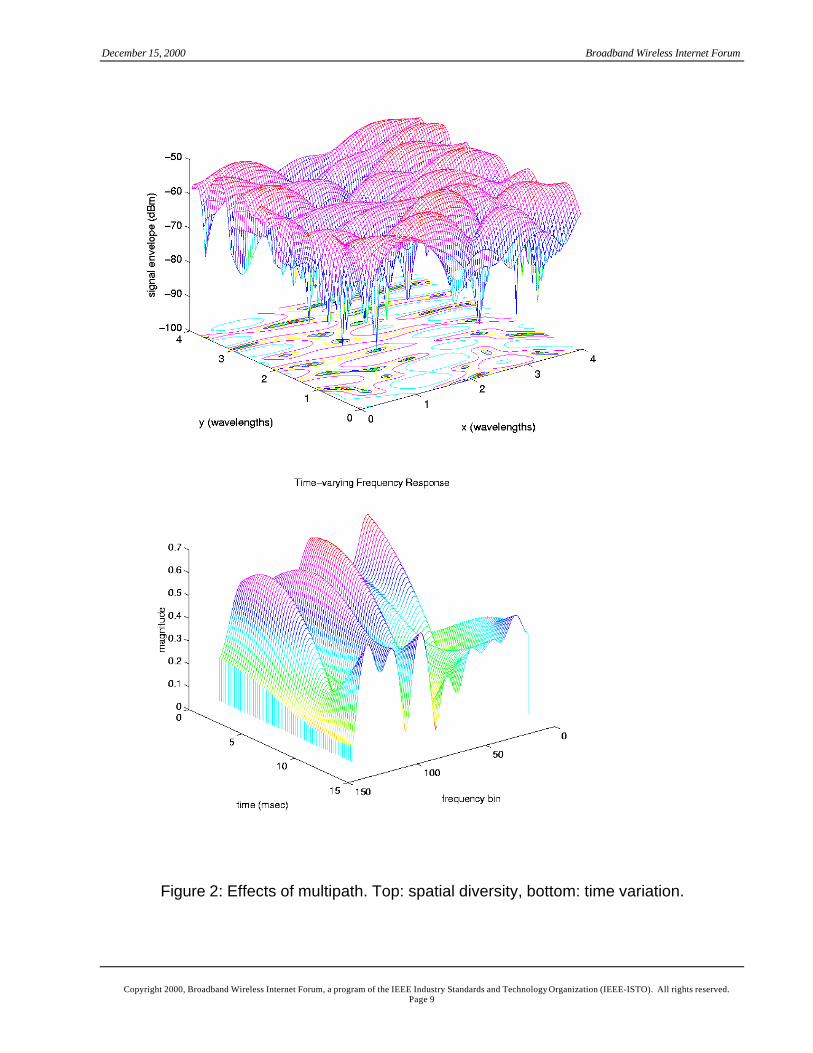
pair as shown on the top in Figure 2. This change in magnitude versus space is known as
fading.
Figure 1: Wireless communication involves multipath transmission.
…
…
SubscriberBaseStation
Paths
December 15, 2000 Broadband Wireless Internet Forum
Copyright 2000, Broadband Wireless Internet Forum, a program of the IEEE Industry Standards and Technology Organization (IEEE-ISTO). All rights reserved.Page 9
Figure 2: Effects of multipath. Top: spatial diversity, bottom: time variation.
December 15, 2000 Broadband Wireless Internet Forum
Copyright 2000, Broadband Wireless Internet Forum, a program of the IEEE Industry Standards and Technology Organization (IEEE-ISTO). All rights reserved.Page 10
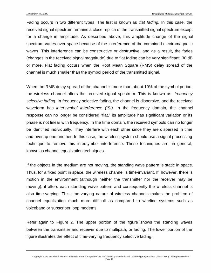
Fading occurs in two different types. The first is known as flat fading. In this case, the
received signal spectrum remains a close replica of the transmitted signal spectrum except
for a change in amplitude. As described above, this amplitude change of the signal
spectrum varies over space because of the interference of the combined electromagnetic
waves. This interference can be constructive or destructive, and as a result, the fades
(changes in the received signal magnitude) due to flat fading can be very significant, 30 dB
or more. Flat fading occurs when the Root Mean Square (RMS) delay spread of the
channel is much smaller than the symbol period of the transmitted signal.
When the RMS delay spread of the channel is more than about 10% of the symbol period,
the wireless channel alters the received signal spectrum. This is known as frequency
selective fading. In frequency selective fading, the channel is dispersive, and the received
waveform has intersymbol interference (ISI). In the frequency domain, the channel
response can no longer be considered “flat,” its amplitude has significant variation or its
phase is not linear with frequency. In the time domain, the received symbols can no longer
be identified individually. They interfere with each other since they are dispersed in time
and overlap one another. In this case, the wireless system should use a signal processing
technique to remove this intersymbol interference. These techniques are, in general,
known as channel equalization techniques.
If the objects in the medium are not moving, the standing wave pattern is static in space.
Thus, for a fixed point in space, the wireless channel is time-invariant. If, however, there is
motion in the environment (although neither the transmitter nor the receiver may be
moving), it alters each standing wave pattern and consequently the wireless channel is
also time-varying. This time-varying nature of wireless channels makes the problem of
channel equalization much more difficult as compared to wireline systems such as
voiceband or subscriber loop modems.
Refer again to Figure 2. The upper portion of the figure shows the standing waves
between the transmitter and receiver due to multipath, or fading. The lower portion of the
figure illustrates the effect of time-varying frequency selective fading.
December 15, 2000 Broadband Wireless Internet Forum
Copyright 2000, Broadband Wireless Internet Forum, a program of the IEEE Industry Standards and Technology Organization (IEEE-ISTO). All rights reserved.Page 11
In fixed, as well as mobile, cellular wireless systems, interference is a significant limiting
factor. Calls in a neighboring cell employing the same channel cause co-channel
interference. Increasing the transmitter power does not remove co-channel interference
because it results in the increased interference to neighboring cells employing the same
channel. In addition, there could be interference due to the existence of other services in
the frequency band. For example, in the San Francisco Bay Area, analog video
interference is present in virtually every MMDS channel (Multipoint Microwave Distribution
System: licensed frequency band at 2.5-2.686 GHz for fixed broadband wireless access
applications in the U.S.).
3 Some Solutions
The most commonly used solution to multipath fading in high data rate fixed wireless
systems is careful site selection and engineering. The goal is to provide a single,
unobstructed path between the transmitter and receiver. This makes it necessary to
establish a Line-of-Sight (LOS) path between the transmitter and receiver antennas. This
careful site selection process is by no means easy to accomplish, typically requiring high
effort and cost. Highly directive antennas are often used to eliminate reflections. Directive
antennas are more expensive and may be aesthetically undesirable. In addition,
establishing an LOS path between the transmitter and receiver antennas is not possible at
every subscriber site in a point-to-multipoint system.
Limiting link range and providing a signal strength margin can be effective against flat
fading. The signal strength (or fade) margin required can be large (tens of dB). This results
in a substantial loss of range and coverage. In addition, space diversity by means of
multiple antennas can help solve the problem. With adequate antenna separation, when
the signal received by one antenna fades, there is a good probability that the signal
strength at the other antenna is still sufficiently large. This greatly reduces the amount of
fade margin required. Hence two spatially separated antennas greatly increase coverage
and range of a system without increasing power. For example, a smaller power amplifier at
the subscriber unit can be used in conjunction with multiple antennas at the base station.
In the same way, transmit diversity may be used to reduce fade margin in the downstream
by using two transmit antennas at the base station.
December 15, 2000 Broadband Wireless Internet Forum
Copyright 2000, Broadband Wireless Internet Forum, a program of the IEEE Industry Standards and Technology Organization (IEEE-ISTO). All rights reserved.Page 12
The conventionally employed technique against frequency selective fading is to use
equalizers. Methods of equalization are well-established. Decision Feedback Equalization
(DFE) is known to provide close to optimum performance once the equalization algorithm
has converged or fully adapted. Furthermore, equalization algorithms with varying degrees
of speed of convergence, computational complexity, and stability are well-understood. The
Least Mean Squares (LMS) algorithm is computationally simple and stable, but converges
slowly. The Recursive Least Squares (RLS) algorithm converges quickly but is far more
complex than LMS. In addition, it has known stability problems. Both algorithms require a
training sequence (blind techniques exist but are not efficient). This is especially important
for packet transmission where the channel may change significantly between
transmissions of different packets. As will be shown later, the complexity of DFE increases
significantly with transmission rate.
In a given system, the conventional method to mitigate co-channel interference is to
increase the distance between cells where the same frequency channel is used, i.e., by
decreasing frequency reuse. However, reducing frequency reuse reduces capacity. For
example, one can keep the total spectrum constant and increase the number of frequency
channels. Then, one can increase the number of cells in the reuse pattern. Consequently,
the co-channel interference of the system decreases together with system capacity.
Mitigation of narrowband interference can be achieved by spreading the signal over the
frequency band. While this can be done via spread spectrum techniques, it can also be
accomplished by using OFDM and coding across the frequency band. Indeed, coding and
OFDM exhibit a spreading gain similar to spread spectrum techniques.
December 15, 2000 Broadband Wireless Internet Forum
Copyright 2000, Broadband Wireless Internet Forum, a program of the IEEE Industry Standards and Technology Organization (IEEE-ISTO). All rights reserved.Page 13
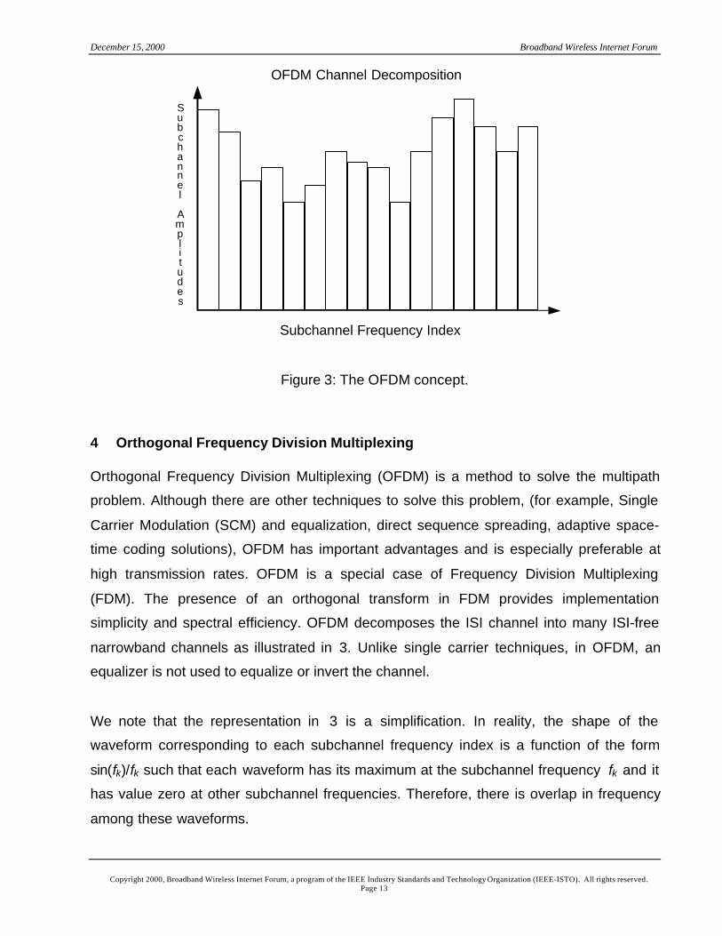
Figure 3: The OFDM concept.
4 Orthogonal Frequency Division Multiplexing
Orthogonal Frequency Division Multiplexing (OFDM) is a method to solve the multipath
problem. Although there are other techniques to solve this problem, (for example, Single
Carrier Modulation (SCM) and equalization, direct sequence spreading, adaptive space-
time coding solutions), OFDM has important advantages and is especially preferable at
high transmission rates. OFDM is a special case of Frequency Division Multiplexing
(FDM). The presence of an orthogonal transform in FDM provides implementation
simplicity and spectral efficiency. OFDM decomposes the ISI channel into many ISI-free
narrowband channels as illustrated in 3. Unlike single carrier techniques, in OFDM, an
equalizer is not used to equalize or invert the channel.
We note that the representation in 3 is a simplification. In reality, the shape of the
waveform corresponding to each subchannel frequency index is a function of the form
sin(fk)/fk such that each waveform has its maximum at the subchannel frequency fk and it
has value zero at other subchannel frequencies. Therefore, there is overlap in frequency
among these waveforms.
Subchannel
Amplitudes
Subchannel Frequency Index
OFDM Channel Decomposition
December 15, 2000 Broadband Wireless Internet Forum
Copyright 2000, Broadband Wireless Internet Forum, a program of the IEEE Industry Standards and Technology Organization (IEEE-ISTO). All rights reserved.Page 14
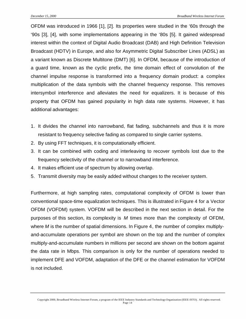
OFDM was introduced in 1966 [1], [2]. Its properties were studied in the ‘60s through the
‘90s [3], [4], with some implementations appearing in the ‘80s [5]. It gained widespread
interest within the context of Digital Audio Broadcast (DAB) and High Definition Television
Broadcast (HDTV) in Europe, and also for Asymmetric Digital Subscriber Lines (ADSL) as
a variant known as Discrete Multitone (DMT) [6]. In OFDM, because of the introduction of
a guard time, known as the cyclic prefix, the time domain effect of convolution of the
channel impulse response is transformed into a frequency domain product: a complex
multiplication of the data symbols with the channel frequency response. This removes
intersymbol interference and alleviates the need for equalizers. It is because of this
property that OFDM has gained popularity in high data rate systems. However, it has
additional advantages:
1. It divides the channel into narrowband, flat fading, subchannels and thus it is more
resistant to frequency selective fading as compared to single carrier systems.
2. By using FFT techniques, it is computationally efficient.
3. It can be combined with coding and interleaving to recover symbols lost due to the
frequency selectivity of the channel or to narrowband interference.
4. It makes efficient use of spectrum by allowing overlap.
5. Transmit diversity may be easily added without changes to the receiver system.
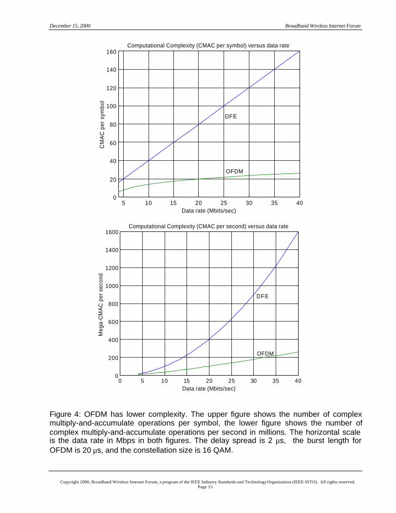
Furthermore, at high sampling rates, computational complexity of OFDM is lower than
conventional space-time equalization techniques. This is illustrated in Figure 4 for a Vector
OFDM (VOFDM) system. VOFDM will be described in the next section in detail. For the
purposes of this section, its complexity is M times more than the complexity of OFDM,
where M is the number of spatial dimensions. In Figure 4, the number of complex multiply-
and-accumulate operations per symbol are shown on the top and the number of complex
multiply-and-accumulate numbers in millions per second are shown on the bottom against
the data rate in Mbps. This comparison is only for the number of operations needed to
implement DFE and VOFDM, adaptation of the DFE or the channel estimation for VOFDM
is not included.
December 15, 2000 Broadband Wireless Internet Forum
Copyright 2000, Broadband Wireless Internet Forum, a program of the IEEE Industry Standards and Technology Organization (IEEE-ISTO). All rights reserved.Page 15
5 10 15 20 25 30 35 400
20
40
60
80
100
120
140
160
OFDM
DFE
Computational Complexity (CMAC per symbol) versus data rate
Data rate (Mbits/sec)
CM
AC
per
sym
bol
0 5 10 15 20 25 30 35 400
200
400
600
800
1000
1200
1400
1600Computational Complexity (CMAC per second) versus data rate
Data rate (Mbits/sec)
Meg
a-C
MA
C p
er s
econ
d
OFDM
DFE
Figure 4: OFDM has lower complexity. The upper figure shows the number of complexmultiply-and-accumulate operations per symbol, the lower figure shows the number ofcomplex multiply-and-accumulate operations per second in millions. The horizontal scaleis the data rate in Mbps in both figures. The delay spread is 2 µs, the burst length forOFDM is 20 µs, and the constellation size is 16 QAM.
December 15, 2000 Broadband Wireless Internet Forum
Copyright 2000, Broadband Wireless Internet Forum, a program of the IEEE Industry Standards and Technology Organization (IEEE-ISTO). All rights reserved.Page 16
It can be calculated that the complexity of the VOFDM system is 2Mlog(Rν) per sample
where M is the number of spatial dimensions, R is the sampling rate, ν is the delay spread
as measured in digital-equivalent channel taps, and where log is due to the FFT
operations VOFDM performs. In comparison, the complexity of the DFE system can be
calculated as 4Rν per sample. This is because of the inner product operation the DFE
carries out. When the complexity figures are calculated per second, the complexity of the
VOFDM system grows log-linearly whereas the complexity of the SCM system grows
quadratically, as shown on the bottom of Figure 4. As a result, the implementation of
VOFDM at high data rates becomes substantially simpler than SCM.
5 VOFDM System
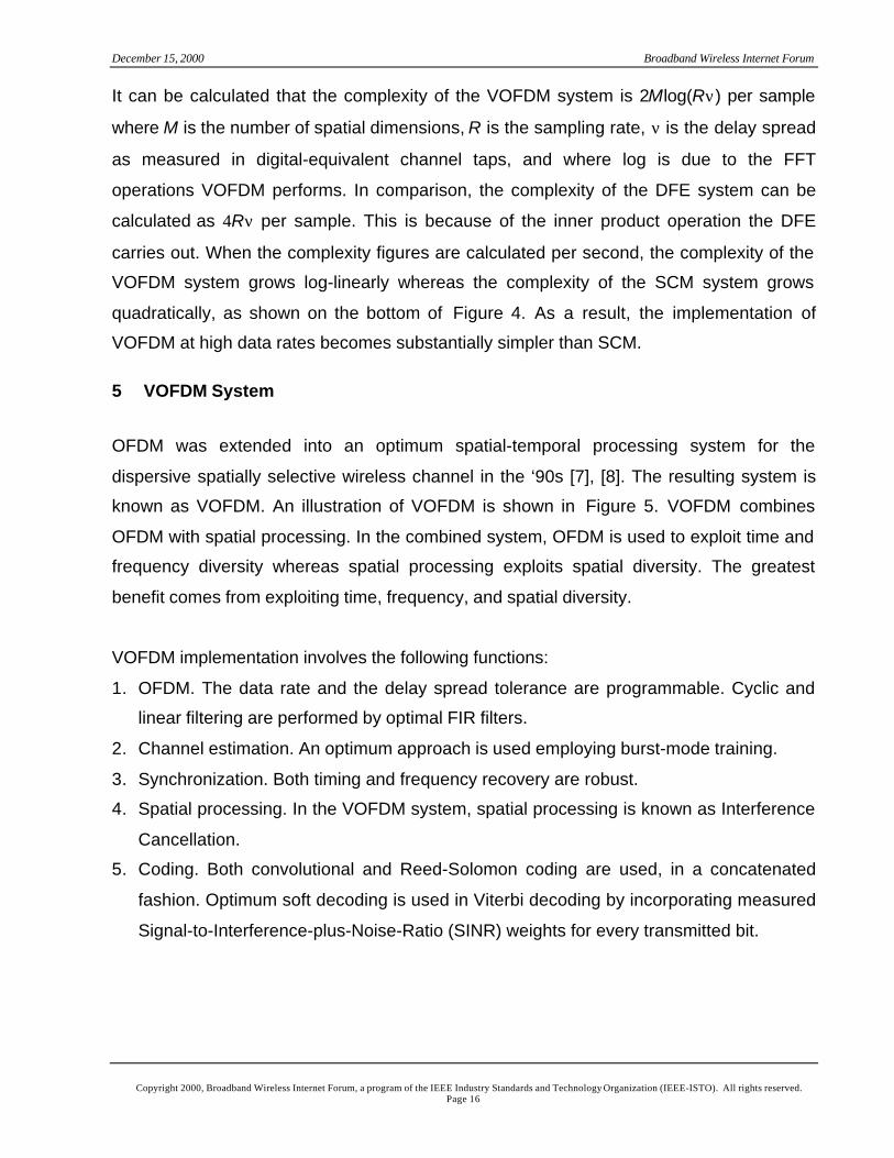
OFDM was extended into an optimum spatial-temporal processing system for the
dispersive spatially selective wireless channel in the ‘90s [7], [8]. The resulting system is
known as VOFDM. An illustration of VOFDM is shown in Figure 5. VOFDM combines
OFDM with spatial processing. In the combined system, OFDM is used to exploit time and
frequency diversity whereas spatial processing exploits spatial diversity. The greatest
benefit comes from exploiting time, frequency, and spatial diversity.
VOFDM implementation involves the following functions:
1. OFDM. The data rate and the delay spread tolerance are programmable. Cyclic and
linear filtering are performed by optimal FIR filters.
2. Channel estimation. An optimum approach is used employing burst-mode training.
3. Synchronization. Both timing and frequency recovery are robust.
4. Spatial processing. In the VOFDM system, spatial processing is known as Interference
Cancellation.
5. Coding. Both convolutional and Reed-Solomon coding are used, in a concatenated
fashion. Optimum soft decoding is used in Viterbi decoding by incorporating measured
Signal-to-Interference-plus-Noise-Ratio (SINR) weights for every transmitted bit.
December 15, 2000 Broadband Wireless Internet Forum
Copyright 2000, Broadband Wireless Internet Forum, a program of the IEEE Industry Standards and Technology Organization (IEEE-ISTO). All rights reserved.Page 17
FFT 1W
WN
IFFT
FFT
FFT
IFFT
V1
IFFT
VN
Figure 5: Space-frequency processing.
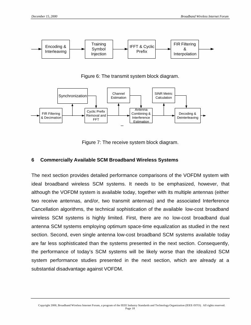
The transmit system block diagram is shown in Figure 6 and the receiver system block
diagram is shown in Figure 7.
December 15, 2000 Broadband Wireless Internet Forum
Copyright 2000, Broadband Wireless Internet Forum, a program of the IEEE Industry Standards and Technology Organization (IEEE-ISTO). All rights reserved.Page 18
Figure 6: The transmit system block diagram.
Figure 7: The receive system block diagram.
6 Commercially Available SCM Broadband Wireless Systems
The next section provides detailed performance comparisons of the VOFDM system with
ideal broadband wireless SCM systems. It needs to be emphasized, however, that
although the VOFDM system is available today, together with its multiple antennas (either
two receive antennas, and/or, two transmit antennas) and the associated Interference
Cancellation algorithms, the technical sophistication of the available low-cost broadband
wireless SCM systems is highly limited. First, there are no low-cost broadband dual
antenna SCM systems employing optimum space-time equalization as studied in the next
section. Second, even single antenna low-cost broadband SCM systems available today
are far less sophisticated than the systems presented in the next section. Consequently,
the performance of today’s SCM systems will be likely worse than the idealized SCM
system performance studies presented in the next section, which are already at a
substantial disadvantage against VOFDM.
Encoding &Interleaving
TrainingSymbolInjection
IFFT & CyclicPrefix
FIR Filtering&
Interpolation
FIR Filtering& Decimation
Synchronization
Cyclic PrefixRemoval and
FFT
ChannelEstimation
AntennaCombining &InterferenceEstimation
SINR MetricCalculation
Decoding &Deinterleaving
December 15, 2000 Broadband Wireless Internet Forum
Copyright 2000, Broadband Wireless Internet Forum, a program of the IEEE Industry Standards and Technology Organization (IEEE-ISTO). All rights reserved.Page 19
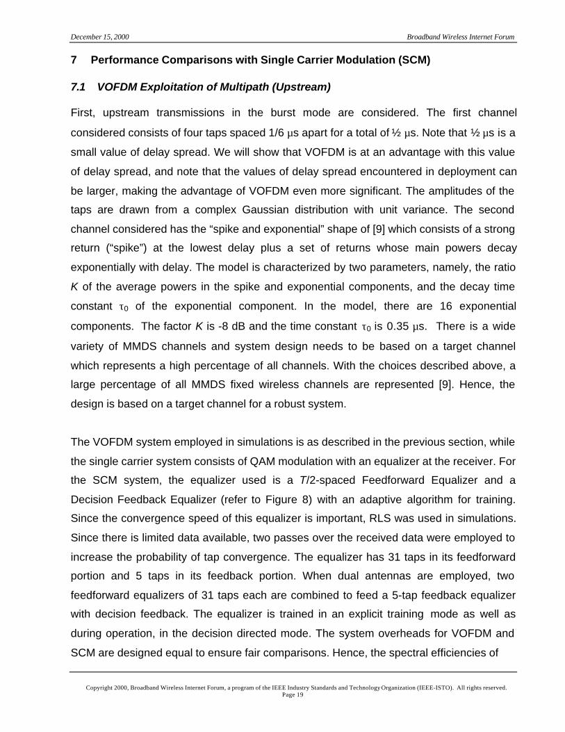
7 Performance Comparisons with Single Carrier Modulation (SCM)
7.1 VOFDM Exploitation of Multipath (Upstream)
First, upstream transmissions in the burst mode are considered. The first channel
considered consists of four taps spaced 1/6 µs apart for a total of ½ µs. Note that ½ µs is a
small value of delay spread. We will show that VOFDM is at an advantage with this value
of delay spread, and note that the values of delay spread encountered in deployment can
be larger, making the advantage of VOFDM even more significant. The amplitudes of the
taps are drawn from a complex Gaussian distribution with unit variance. The second
channel considered has the “spike and exponential” shape of [9] which consists of a strong
return (“spike”) at the lowest delay plus a set of returns whose main powers decay
exponentially with delay. The model is characterized by two parameters, namely, the ratio
K of the average powers in the spike and exponential components, and the decay time
constant τ0 of the exponential component. In the model, there are 16 exponential
components. The factor K is -8 dB and the time constant τ0 is 0.35 µs. There is a wide
variety of MMDS channels and system design needs to be based on a target channel
which represents a high percentage of all channels. With the choices described above, a
large percentage of all MMDS fixed wireless channels are represented [9]. Hence, the
design is based on a target channel for a robust system.
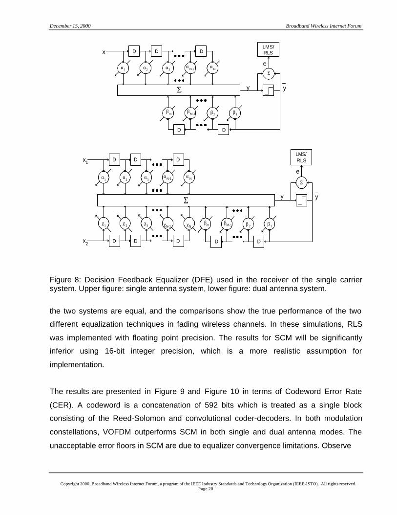
The VOFDM system employed in simulations is as described in the previous section, while
the single carrier system consists of QAM modulation with an equalizer at the receiver. For
the SCM system, the equalizer used is a T/2-spaced Feedforward Equalizer and a
Decision Feedback Equalizer (refer to Figure 8) with an adaptive algorithm for training.
Since the convergence speed of this equalizer is important, RLS was used in simulations.
Since there is limited data available, two passes over the received data were employed to
increase the probability of tap convergence. The equalizer has 31 taps in its feedforward
portion and 5 taps in its feedback portion. When dual antennas are employed, two
feedforward equalizers of 31 taps each are combined to feed a 5-tap feedback equalizer
with decision feedback. The equalizer is trained in an explicit training mode as well as
during operation, in the decision directed mode. The system overheads for VOFDM and
SCM are designed equal to ensure fair comparisons. Hence, the spectral efficiencies of
December 15, 2000 Broadband Wireless Internet Forum
Copyright 2000, Broadband Wireless Internet Forum, a program of the IEEE Industry Standards and Technology Organization (IEEE-ISTO). All rights reserved.Page 20
Figure 8: Decision Feedback Equalizer (DFE) used in the receiver of the single carriersystem. Upper figure: single antenna system, lower figure: dual antenna system.
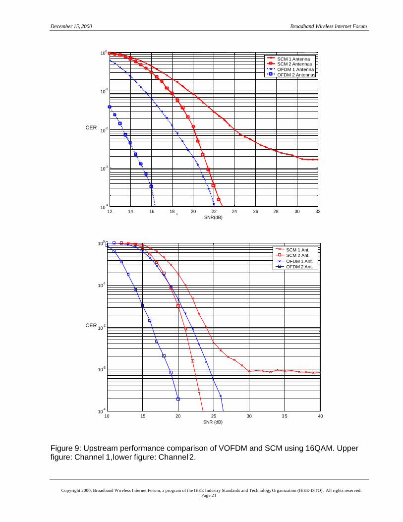
the two systems are equal, and the comparisons show the true performance of the two
different equalization techniques in fading wireless channels. In these simulations, RLS
was implemented with floating point precision. The results for SCM will be significantly
inferior using 16-bit integer precision, which is a more realistic assumption for
implementation.
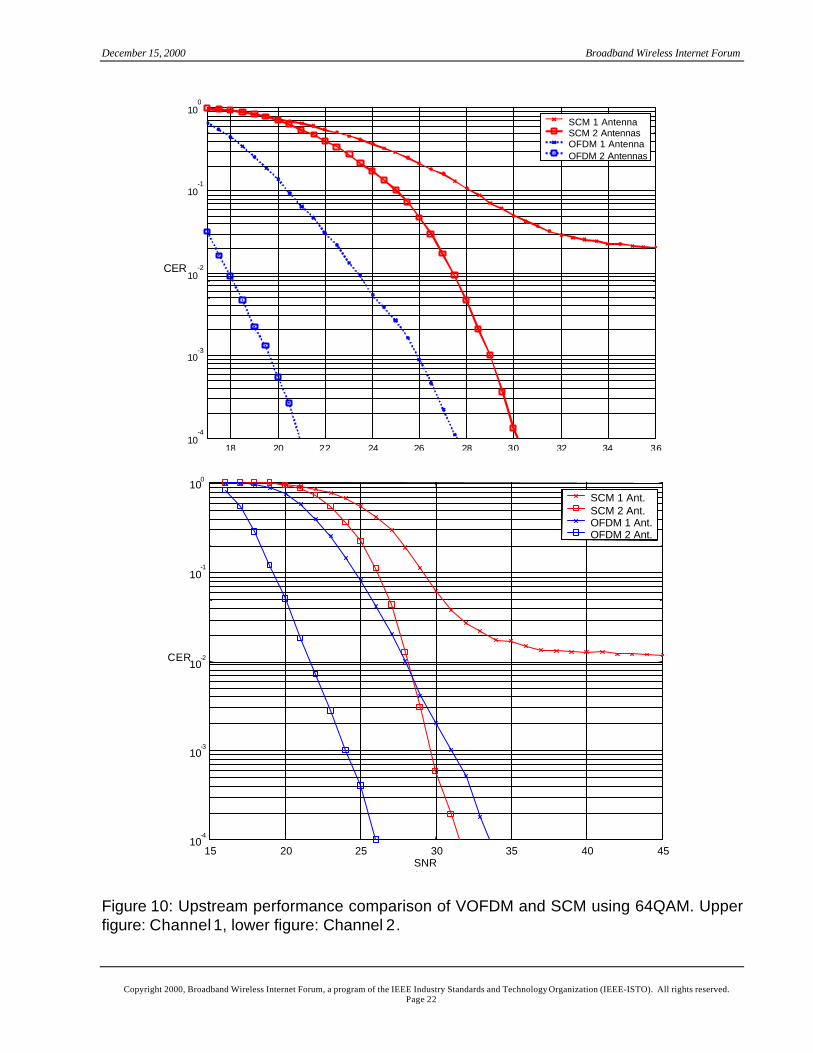
The results are presented in Figure 9 and Figure 10 in terms of Codeword Error Rate
(CER). A codeword is a concatenation of 592 bits which is treated as a single block
consisting of the Reed-Solomon and convolutional coder-decoders. In both modulation
constellations, VOFDM outperforms SCM in both single and dual antenna modes. The
unacceptable error floors in SCM are due to equalizer convergence limitations. Observe
D D D
α1
Σ
α2 α3α
N-1α
N
D D
β2β
mβ
M-1 β1
Σ
x
y
e
y
LMS/RLS
Σ
D D
β2βm βM-1 β1
Σ
y
e
y
LMS/RLSx1 D D D
α1 α2 α3αN-1 αN
x2 D D D
χ1 χ2 χ3 χN-1 χN
December 15, 2000 Broadband Wireless Internet Forum
Copyright 2000, Broadband Wireless Internet Forum, a program of the IEEE Industry Standards and Technology Organization (IEEE-ISTO). All rights reserved.Page 21
12 14 16 18 20 22 24 26 28 30 3210
-4
10-3
10-2
10-1
100
CER
SNR(dB)
SCM 1 AntennaSCM 2 AntennasOFDM 1 AntennaOFDM 2 Antennas
Figure 9: Upstream performance comparison of VOFDM and SCM using 16QAM. Upperfigure: Channel 1,lower figure: Channel 2.
10 15 20 25 30 35 4010
-4
10-3
10-2
10-1
100
SNR (dB)
CER
SCM 1 Ant.SCM 2 Ant.OFDM 1 Ant.OFDM 2 Ant.
December 15, 2000 Broadband Wireless Internet Forum
Copyright 2000, Broadband Wireless Internet Forum, a program of the IEEE Industry Standards and Technology Organization (IEEE-ISTO). All rights reserved.Page 22
18 20 22 24 26 28 30 32 34 3610
-4
10-3
10-2
10-1
100
CER
SNR(dB)
SCM 1 AntennaSCM 2 AntennasOFDM 1 AntennaOFDM 2 Antennas
Figure 10: Upstream performance comparison of VOFDM and SCM using 64QAM. Upperfigure: Channel 1, lower figure: Channel 2.
15 20 25 30 35 40 4510
-4
10-3
10-2
10-1
100
SNR(dB)
CER
SCM 1 Ant.SCM 2 Ant.OFDM 1 Ant.OFDM 2 Ant.
December 15, 2000 Broadband Wireless Internet Forum
Copyright 2000, Broadband Wireless Internet Forum, a program of the IEEE Industry Standards and Technology Organization (IEEE-ISTO). All rights reserved.Page 23
OFDM Advantage at CER = 10-4
SingleAntenna
Dual Antenna
16 QAM Channel 1 ∞ 6 dB16 QAM Channel 2 ∞ 3 dB64 QAM Channel 1 ∞ 9 dB64 QAM Channel 2 ∞ 6 dB
that the OFDM advantage at CER = 10-4 is as shown in the table above. To implement a
dual antenna system in VOFDM, the two antenna outputs are combined using SINR
combining, whereas for SCM, an optimal space-time equalizer as described above is
employed. Note that VOFDM system performs SINR combining, however there are no
SCM space-time equalizer products for MMDS applications in the market. Further gains
are possible for VOFDM if Interference Cancellation is used. Further spatial processing
gains are also possible if the simulated channels exhibit less correlation and if flat fading
gains are included in the results. In general, Figure 9 and Figure 10 show that a VOFDM
system provides more capacity. This is because in order to operate at the same error rate,
SCM either needs more coding, or more SNR, or more Carrier-to-Interference ratio (C/I).
7.2 VOFDM and SCM in Continuous Carrier Demodulation (Downstream)
As opposed to Section 7.1 where we compared VOFDM and SCM systems in the
upstream direction in the burst mode, in this subsection we compare VOFDM and SCM
systems in downstream carrier demodulation. In this comparison, VOFDM and SCM
system efficiencies are designed approximately equal. The simulated 6 MHz channel is a
similar to Channel 2 of the previous section, with the addition of time varying components
using Jakes’ model at 1 Hz [10]. The SCM system equalizer employs a fully adapted
equalizer using the Least Mean Squares (LMS) algorithm. The receiver employs single or
dual antennas. VOFDM employs Interference Cancellation whereas SCM employs
optimum space-time equalization. System parameters are as follows: FFT size is 512
symbols and 32 bytes are used for the cyclic prefix. Convolutional code rate is 2/3, and the
Reed-Solomon code parameters are (n, k) = (252, 232). The equalizer uses 48
feedforward taps for each antenna and 12 feedback taps that are common.
December 15, 2000 Broadband Wireless Internet Forum
Copyright 2000, Broadband Wireless Internet Forum, a program of the IEEE Industry Standards and Technology Organization (IEEE-ISTO). All rights reserved.Page 24
15 20 25 30 35
10-4
10-3
10-2
10-1
100
SNR (dB)
OFDM, fd = 0HzSCM, f
d = 0Hz
OFDM, fd = 1HzSCM, fd = 1Hz
CER
10 15 20 25 3010
-4
10-3
10-2
10-1
100
SNR (dB)
OFDM, fd = 0Hz
SCM, fd = 0HzOFDM, fd = 1Hz
SCM, fd = 1Hz
CER
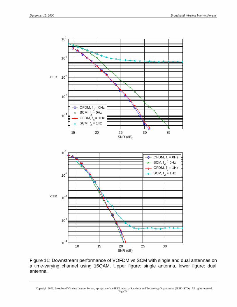
Figure 11: Downstream performance of VOFDM vs SCM with single and dual antennas ona time-varying channel using 16QAM. Upper figure: single antenna, lower figure: dualantenna.
December 15, 2000 Broadband Wireless Internet Forum
Copyright 2000, Broadband Wireless Internet Forum, a program of the IEEE Industry Standards and Technology Organization (IEEE-ISTO). All rights reserved.Page 25
20 25 30 35 40 45 5010
-4
10-3
10-2
10-1
100
SNR (dB)
OFDM, fd = 0HzSCM, fd = 0HzOFDM, fd = 1HzSCM, fd = 1Hz
CER
10 15 20 25 30 3510
-4
10-3
10-2
10-1
100
SNR (dB)
OFDM, fd = 0HzSCM, f
d = 0Hz
OFDM, fd = 1HzSCM, f
d = 1Hz
CER
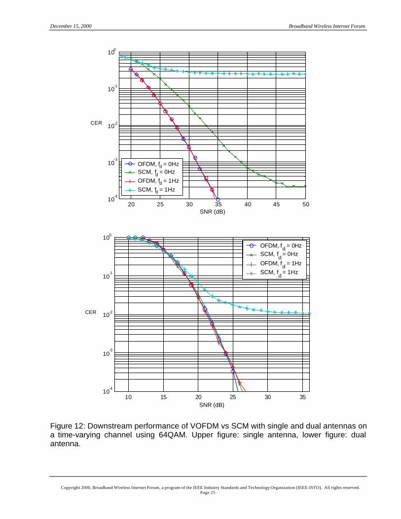
Figure 12: Downstream performance of VOFDM vs SCM with single and dual antennas ona time-varying channel using 64QAM. Upper figure: single antenna, lower figure: dualantenna.
December 15, 2000 Broadband Wireless Internet Forum
Copyright 2000, Broadband Wireless Internet Forum, a program of the IEEE Industry Standards and Technology Organization (IEEE-ISTO). All rights reserved.Page 26
16QAM results are shown in Figure 11 and Figure 12 for single and dual antennas. First,
note the presence of error floors with SCM systems. Error floors depend on the channel,
number of antennas, Doppler frequency, and also the constellation type. Further
experimentation has shown that further training does not eliminate these error floors. The
OFDM system does not show error floors, and its performance does not deteriorate in the
presence of the time-varying channel.
64QAM results are shown in Figure 12. While the dual antenna SCM system equals the
performance of VOFDM for the time-invariant channel, it cannot adapt to the time-varying
channel, whereas again, VOFDM performance does not deteriorate in the presence of the
time-varying channel.
We would like to reiterate that while VOFDM system implements dual antennas, there is
no known implementation of a dual antenna SCM system for MMDS broadband
applications.
7.3 VOFDM Transmit Diversity
Transmit diversity can be used either on the uplink, or the downlink. Transmit diversity
uses a second transmit antenna, and reduces the required fading margin by exploiting the
lack of correlation between the fast fading that each transmit path encounters. Transmit
diversity requires additional components beyond the standard dual-receiver configuration:
a signal modifier as described below, and a second analog chain. Note that in dual
receive diversity systems, the extra antenna and outdoor equipment is already available.
The receiver needs no modification to support transmit diversity.
In some installation scenarios, the channel will have little delay spread. In this case, the
signals from the two antennas could arrive at the receiver 180 degrees out of phase
across the entire frequency band. To remedy this problem, the signal modifier is used on
one transmit antenna. One implementation of the signal modifier is a pure delay element.
By delaying the signal sent by the second antenna, there is no single phase of one
antenna with respect to the other that will cause a fade of the entire band; instead, a series
December 15, 2000 Broadband Wireless Internet Forum
Copyright 2000, Broadband Wireless Internet Forum, a program of the IEEE Industry Standards and Technology Organization (IEEE-ISTO). All rights reserved.Page 27
of notches are formed across the channel. While these notches introduce SNR
degradation over the single antenna performance, complete destructive interference at all
frequencies is avoided. With this delay element, the addition of a second antenna clearly
improves the link budget, because the notch degradation is more than made up by the
reduction in the fading margin. Other implementations of the signal modifier, besides pure
delay, are possible. Another possibility is to modify the magnitude response, or a
combination of the magnitude and phase responses. The design philosophy using these
methods is very similar to the pure delay modifier.
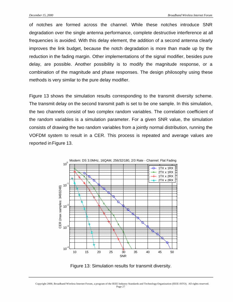
Figure 13 shows the simulation results corresponding to the transmit diversity scheme.
The transmit delay on the second transmit path is set to be one sample. In this simulation,
the two channels consist of two complex random variables. The correlation coefficient of
the random variables is a simulation parameter. For a given SNR value, the simulation
consists of drawing the two random variables from a jointly normal distribution, running the
VOFDM system to result in a CER. This process is repeated and average values are
reported in Figure 13.
10 15 20 25 30 35 40 45 5010
-4
10-3
10-2
10-1
100
SNR
CE
R (
max
sam
ples
: 349
3248
)
Modem: DS 3.0MHz, 16QAM, 256/32/180, 2/3 Rate - Channel: Flat Fading
1TX x 1RX2TX x 1RX1TX x 2RX2TX x 2RX
Figure 13: Simulation results for transmit diversity.
December 15, 2000 Broadband Wireless Internet Forum
Copyright 2000, Broadband Wireless Internet Forum, a program of the IEEE Industry Standards and Technology Organization (IEEE-ISTO). All rights reserved.Page 28
7.4 VOFDM Receive Diversity
Receive diversity, like transmit diversity, confers a significant advantage. A system using
only one antenna must employ a larger fade margin. The effect of larger fade margin is
illustrated in two examples below. The first example is a macrocell scenario, in which cell
size is limited by transmit power and receiver noise. The second scenario is a microcell
scenario, in which capacity is limited by the mean C/I with which the cellular system can
operate.
We compare a VOFDM system employing two receive antenna diversity to an SCM
system employing one receive antenna. We assume that the channel gain from the
headend transmitter to each Subscriber Unit (SU) receive antenna fades independently
with a Rayleigh distribution. The channel for each antenna contains negligible delay
spread. We use the Codeword Error Rate (CER) at the SU as a measure of performance;
in general, a minimum received SNR is needed to reduce the CER to acceptable levels.
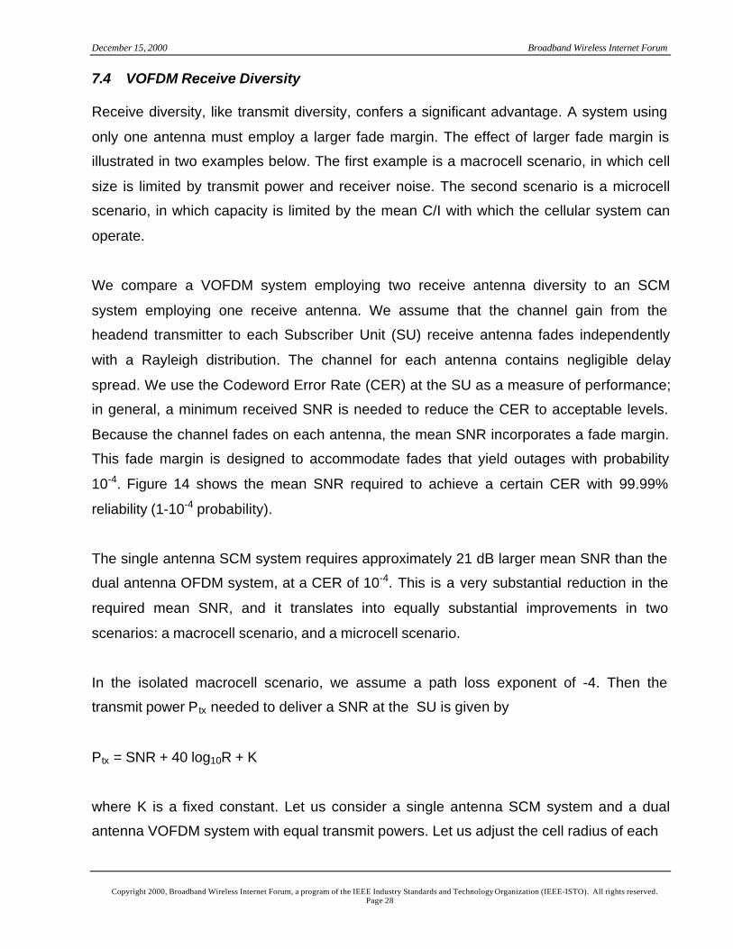
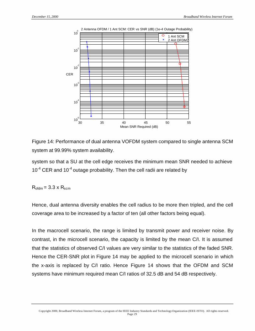
Because the channel fades on each antenna, the mean SNR incorporates a fade margin.
This fade margin is designed to accommodate fades that yield outages with probability
10-4. Figure 14 shows the mean SNR required to achieve a certain CER with 99.99%
reliability (1-10-4 probability).
The single antenna SCM system requires approximately 21 dB larger mean SNR than the
dual antenna OFDM system, at a CER of 10-4. This is a very substantial reduction in the
required mean SNR, and it translates into equally substantial improvements in two
scenarios: a macrocell scenario, and a microcell scenario.
In the isolated macrocell scenario, we assume a path loss exponent of -4. Then the
transmit power P tx needed to deliver a SNR at the SU is given by
Ptx = SNR + 40 log10R + K
where K is a fixed constant. Let us consider a single antenna SCM system and a dual
antenna VOFDM system with equal transmit powers. Let us adjust the cell radius of each
December 15, 2000 Broadband Wireless Internet Forum
Copyright 2000, Broadband Wireless Internet Forum, a program of the IEEE Industry Standards and Technology Organization (IEEE-ISTO). All rights reserved.Page 29
30 35 40 45 50 5510
-5
10-4
10-3
10-2
10-1
100
Mean SNR Required (dB)
CER
2 Antenna OFDM / 1 Ant SCM: CER vs SNR (dB) (1e-4 Outage Probability)
1 Ant SCM2 Ant OFDM
Figure 14: Performance of dual antenna VOFDM system compared to single antenna SCM
system at 99.99% system availability.
system so that a SU at the cell edge receives the minimum mean SNR needed to achieve
10-4 CER and 10-4 outage probability. Then the cell radii are related by
Rofdm = 3.3 x Rscm
Hence, dual antenna diversity enables the cell radius to be more then tripled, and the cell
coverage area to be increased by a factor of ten (all other factors being equal).
In the macrocell scenario, the range is limited by transmit power and receiver noise. By
contrast, in the microcell scenario, the capacity is limited by the mean C/I. It is assumed
that the statistics of observed C/I values are very similar to the statistics of the faded SNR.
Hence the CER-SNR plot in Figure 14 may be applied to the microcell scenario in which
the x-axis is replaced by C/I ratio. Hence Figure 14 shows that the OFDM and SCM
systems have minimum required mean C/I ratios of 32.5 dB and 54 dB respectively.
December 15, 2000 Broadband Wireless Internet Forum
Copyright 2000, Broadband Wireless Internet Forum, a program of the IEEE Industry Standards and Technology Organization (IEEE-ISTO). All rights reserved.Page 30
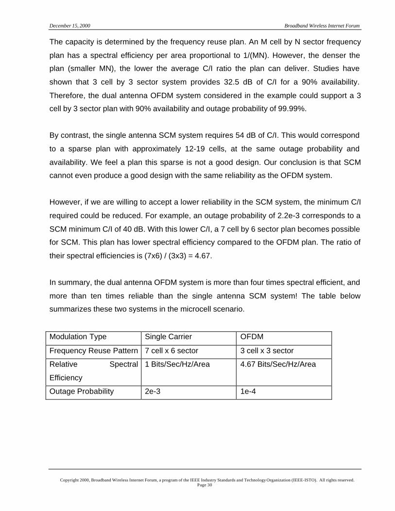
The capacity is determined by the frequency reuse plan. An M cell by N sector frequency
plan has a spectral efficiency per area proportional to 1/(MN). However, the denser the
plan (smaller MN), the lower the average C/I ratio the plan can deliver. Studies have
shown that 3 cell by 3 sector system provides 32.5 dB of C/I for a 90% availability.
Therefore, the dual antenna OFDM system considered in the example could support a 3
cell by 3 sector plan with 90% availability and outage probability of 99.99%.
By contrast, the single antenna SCM system requires 54 dB of C/I. This would correspond
to a sparse plan with approximately 12-19 cells, at the same outage probability and
availability. We feel a plan this sparse is not a good design. Our conclusion is that SCM
cannot even produce a good design with the same reliability as the OFDM system.
However, if we are willing to accept a lower reliability in the SCM system, the minimum C/I
required could be reduced. For example, an outage probability of 2.2e-3 corresponds to a
SCM minimum C/I of 40 dB. With this lower C/I, a 7 cell by 6 sector plan becomes possible
for SCM. This plan has lower spectral efficiency compared to the OFDM plan. The ratio of
their spectral efficiencies is (7x6) / (3x3) = 4.67.
In summary, the dual antenna OFDM system is more than four times spectral efficient, and
more than ten times reliable than the single antenna SCM system! The table below
summarizes these two systems in the microcell scenario.
Modulation Type Single Carrier OFDM
Frequency Reuse Pattern 7 cell x 6 sector 3 cell x 3 sector
Relative Spectral
Efficiency
1 Bits/Sec/Hz/Area 4.67 Bits/Sec/Hz/Area
Outage Probability 2e-3 1e-4
December 15, 2000 Broadband Wireless Internet Forum
Copyright 2000, Broadband Wireless Internet Forum, a program of the IEEE Industry Standards and Technology Organization (IEEE-ISTO). All rights reserved.Page 31
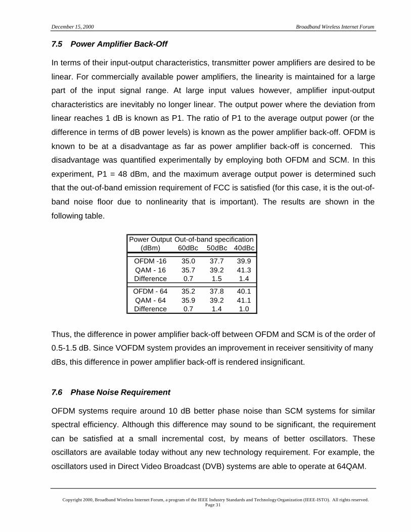
7.5 Power Amplifier Back-Off
In terms of their input-output characteristics, transmitter power amplifiers are desired to be
linear. For commercially available power amplifiers, the linearity is maintained for a large
part of the input signal range. At large input values however, amplifier input-output
characteristics are inevitably no longer linear. The output power where the deviation from
linear reaches 1 dB is known as P1. The ratio of P1 to the average output power (or the
difference in terms of dB power levels) is known as the power amplifier back-off. OFDM is
known to be at a disadvantage as far as power amplifier back-off is concerned. This
disadvantage was quantified experimentally by employing both OFDM and SCM. In this
experiment, P1 = 48 dBm, and the maximum average output power is determined such
that the out-of-band emission requirement of FCC is satisfied (for this case, it is the out-of-
band noise floor due to nonlinearity that is important). The results are shown in the
following table.
Thus, the difference in power amplifier back-off between OFDM and SCM is of the order of
0.5-1.5 dB. Since VOFDM system provides an improvement in receiver sensitivity of many
dBs, this difference in power amplifier back-off is rendered insignificant.
7.6 Phase Noise Requirement
OFDM systems require around 10 dB better phase noise than SCM systems for similar
spectral efficiency. Although this difference may sound to be significant, the requirement
can be satisfied at a small incremental cost, by means of better oscillators. These
oscillators are available today without any new technology requirement. For example, the
oscillators used in Direct Video Broadcast (DVB) systems are able to operate at 64QAM.
Power Output Out-of-band specification(dBm) 60dBc 50dBc 40dBc
OFDM -16 35.0 37.7 39.9QAM - 16 35.7 39.2 41.3Difference 0.7 1.5 1.4
OFDM - 64 35.2 37.8 40.1QAM - 64 35.9 39.2 41.1Difference 0.7 1.4 1.0
December 15, 2000 Broadband Wireless Internet Forum
Copyright 2000, Broadband Wireless Internet Forum, a program of the IEEE Industry Standards and Technology Organization (IEEE-ISTO). All rights reserved.Page 32
7.7 Timing Offset
OFDM transmits data OFDM bursts, or effectively a larger “symbol” as compared to the
individual symbols modulating each frequency component. Furthermore, the cyclic prefix
provides redundant data around an OFDM burst. These factors make an OFDM system
highly insensitive to timing offset. This feature of OFDM is widely documented (see, for
example, [11, p. 78], [12, Ch. 5]).
7.8 Frequency Offset
OFDM systems have significant sensitivity to frequency offset. However, as in phase noise
requirements, the techniques required are quite well established and can be implemented
with little or no price impacts. There are various techniques published in the literature (see
for example [12, Ch. 5]).
8 Summary and Conclusions
In this paper we provided a simulation- and experimentation-based comparison of Vector
Orthogonal Frequency Division Multiplexing and Single Carrier Modulation systems for
broadband wireless local loop applications. The results show that
• In the upstream direction where the operation is burst-mode, VOFDM is substantially
superior to SCM. The CER performance of SCM, even with double-pass floating point
precision RLS equalization, is unacceptable with a single antenna (for the same
transmission overhead as a VOFDM system), and 3-9 dB worse than VOFDM with dual
antennas.
• In the downstream direction where the operation is continuous demodulation, VOFDM
provides dual antenna capability at a lower complexity. Low cost dual antenna SCM
systems do not commercially exist today, and even if they were to be built, they would
require significantly higher complexity. In the channel simulated (covering a large
number of MMDS channels), SCM using LMS does not converge with a single
antenna. It can work in a time-invariant channel with two antennas, but then, it does not
work in a time varying channel with frequency 1 Hz. VOFDM performance does not
deteriorate in this channel.
December 15, 2000 Broadband Wireless Internet Forum
Copyright 2000, Broadband Wireless Internet Forum, a program of the IEEE Industry Standards and Technology Organization (IEEE-ISTO). All rights reserved.Page 33
• VOFDM has some limitations: power amplifier back-off and phase noise. Its power
amplifier back-off requirements are about 0.5-1.5 dB lower than that of SCM. However,
this difference is more than compensated for by means of better sensitivity receivers
supplied in VOFDM. In terms of phase noise, the difference results in a small cost
differential.
Overall, there is no doubt that VOFDM is superior to SCM for MMDS broadband wireless
local loop applications. A given VOFDM MMDS broadband wireless local loop system will
have a larger capacity than a comparable SCM one.
9 Acknowledgements
Comments and suggestions by Mark Dale and Dave Hartman (Broadcom), Jamal
Hamdani (Moseley), Nigel King (Piping Hot Networks), Mike Burgess and Ali Zamanian
(Fluor), and Saeid Safavi (WFI) are appreciated.
December 15, 2000 Broadband Wireless Internet Forum
Copyright 2000, Broadband Wireless Internet Forum, a program of the IEEE Industry Standards and Technology Organization (IEEE-ISTO). All rights reserved.Page 34
References
[1] R. W. Chang, “Synthesis of band-limited orthogonal signals for multichannel data
transmission,” Bell System Technical Journal, Vol. 45, pp. 1775-1796, December
1966.
[2] R. W. Chang, “Orthogonal frequency division multiplexing,” U.S. Patent 3488445
January 1970.
[3] R. W. Chang and R. A Gibby, “A theoretical study of performance of an orthogonal
multiplexing data transmission scheme,” IEEE Transactions on Communication
Technology, Vol. 16, pp. 529-540, August 1968.
[4] S. B. Weinstein and P. M. Ebert, “Data transmission by frequency-division
multiplexing using the discrete Fourier transform,” IEEE Transactions on
Communication Technology, Vol. 19, pp. 628-634, October 1971.
[5] L. J. Cimini, Jr., “Analysis and simulation of a digital mobile channel using orthogonal
frequency division multiplexing,” IEEE Transactions on Communications, Vol. 33, pp.
665-675, July 1985.
[6] T. Starr, J. M. Cioffi, P. Silverman, Understanding Digital Subscriber Line
Technology, Prentice Hall, January 1999.
[7] G. G. Raleigh, J. M. Cioffi, “Spatio-temporal coding for wireless communications,”
Proc. IEEE 1996 Global Communications Conference, pp. 1809-1814, November
1996.
[8] G. G. Raleigh and V. K. Jones, “Multivariate modulation and coding for wireless
communication,” IEEE Journal on Selected Areas in Communications, Vol. 17, pp.
851-866, May 1999.
[9] V. Erceg, D. G. Michelson, S. S. Ghassemzadeh, L. J. Greenstein, A. J. Rustako, P.
B. Guerlain, M. K. Dennison, R. S. Roman, D. J. Barnickel, S. C. Wang, and R. R.
Miller, “A model for the multipath delay profile of fixed wireless channels,” IEEE
Journal on Selected Areas in Communications, Vol. 17, pp. 399-409, March 1999.
[10] W. C. Jakes, Microwave Mobile Communications, IEEE Press, 1974.
[11] R. van Nee and R. Prasad, OFDM for Wireless Multimedia Communications, Artech
House, 2000.
December 15, 2000 Broadband Wireless Internet Forum
Copyright 2000, Broadband Wireless Internet Forum, a program of the IEEE Industry Standards and Technology Organization (IEEE-ISTO). All rights reserved.Page 35
[12] A. R. S. Bahai and B. R. Saltzberg, Multi-Carrier Digital Communications: Theory and
Applications of OFDM, Kluwer Academic/Plenum Publishers, 1999.