broadband over power line (bpl) equipment authorization ... · bpl general information access bpl -...
TRANSCRIPT

February 2006 TCB Workshop 1
Broadband over Power Line (BPL) Broadband over Power Line (BPL) Equipment Authorization Equipment Authorization -- DetailedDetailed
Andy LeimerOET Equipment Authorization Branch
FCC Laboratory
February 2006 TCB Workshop 2
BPL RulesBPL RulesR&O (FCC 04-245) - New Part 15 Subpart Ghttp://hraunfoss.fcc.gov/edocs_public/attachmatch/FCC-04-245A1.pdfMeasurement procedures in Appendix CErratum DOC-254180A1.docTransition Provisions– New equipment must comply by July 7, 2006– Equipment installed by this date may operate for
duration of useful life if there are no reported instances of harmful interference
Currently, TCBs cannot authorize Access BPL devices
February 2006 TCB Workshop 3
BPL General InformationBPL General InformationAccess BPL - EUT defined as device (not system) requiring Certification
– May include the electronic equipment enclosure, coupling device, and medium voltage lines that are injected (Phase and neutral if both are injected)
– Pole ground wires not considered to be part of EUT
All BPL system components require separate certification
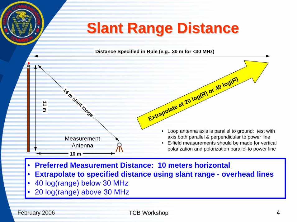
Overhead line distance correction based on Slant Range distance - measurement antenna to the closest part of the EUT
February 2006 TCB Workshop 4
Slant Range DistanceSlant Range Distance
10 m
11 m
MeasurementAntenna
14 m slant range
Distance Specified in Rule (e.g., 30 m for <30 MHz)
• Preferred Measurement Distance: 10 meters horizontal• Extrapolate to specified distance using slant range - overhead lines• 40 log(range) below 30 MHz• 20 log(range) above 30 MHz
Extrapolate at 20 log(R) or 40 log(R)
• Loop antenna axis is parallel to ground: test with axis both parallel & perpendicular to power line
• E-field measurements should be made for vertical polarization and polarization parallel to power line
February 2006 TCB Workshop 5
Operational DescriptionOperational DescriptionDescribe device function – injectors, extractors, repeaters, boosters, concentrators, couplers, etc.Describe BPL coupling of the medium voltage line (if applicable) distribution to customer premises (coupled around low voltage transformer, directly through the low voltage transformer, IEEE 802.11, other)Technical Characteristics - Frequency range(s), BW, Modulation, variable power setting, notch filtering, duty factor, data rates, etc.Configuration – setup and control, signal routing, how is device used in a BPL systemNotch Capabilities – frequencies, 20dB BW, control, cold power-up defaults
February 2006 TCB Workshop 6
Test Site Description Test Site Description In-Situ Testing (Part 15.31(d))– three typical overhead line installations and three typical underground line installations
Overhead Line – photos showing unobstructed access to pole containing electronic enclosure and couplers
– Demonstrate that for medium voltage lines measurements can be made for distance of 1 wavelength (mid-band) at a minimum 10m horizontal distance from the power line
Underground Line – photos showing that the selected transformer is away from cable TV and telephone utility connection boxes (as best as possible)
– 16 radials (as best as possible)
February 2006 TCB Workshop 7
Test Setup DescriptionTest Setup DescriptionIn-situ testing does not require FCC approved test lab but
Plot showing ambient conditions (recommended since noisy conditions cause inconclusive QP measurements)
Antennas– Loop antennas: 1m antenna height, maximized from parallel to
line to 90 degrees (perpendicular to line)• Active Loop < 30 MHz• Passive Loop < 30 MHz
– Bicon > 30 MHz: Scan from 1 to 4m antenna height, H & V polarization
External Amplifiers, low-pass and high-pass filters used to reduce AM/FM & TV broadcast band effects
February 2006 TCB Workshop 8
Test Setup Description (Test Setup Description (Con’tCon’t.).)
Describe how the maximum or near-maximum RF injection duty factor is achieved – either by creating data flow through the system or by use of a test mode
– Data Burst Rate (description or plot)• 20 Hz minimum burst rate as specified in Part 15.35 (Note)
Otherwise, a peak detector must be used
Measurement distances along power line at 0, 1/4,1/2, 3/4, and 1 wavelength down the line from device, based on the mid-band frequency and any adjustments
– Additional measurement positions are required if the mid-band frequency exceeds the lowest injection frequency by more than a factor of 2
February 2006 TCB Workshop 9
Test ReportTest ReportConducted emissions not requiredRadiated Emission Limits
– Section 15.209 at frequencies < 30 MHz– Section 15.109 at frequencies > 30 MHz
Note: Class A limits may be used if applicableQP measurements
– Maximize the BPL data rate for uplink and downlink– Report the six highest radiated emissions relative to
the limit– Sweep the band that includes the maximum emissions
(Note: maximum 50 kHz sweeps for QP measurements < 30 kHz (9kHz RBW))
February 2006 TCB Workshop 10
Test Report (Test Report (Con’tCon’t))
The measurement procedures for medium voltage lines and low voltage lines are identical. Medium and low voltage lines (if applicable) must both be tested
February 2006 TCB Workshop 11
Access BPL Certification Access BPL Certification ––equipment class BPLequipment class BPL
FCC ID/Location – no special requirements
Attestation Statement(s)External PhotosBlock DiagramTest ReportTest Set-up Photos – all in-situ sitesUser’s Manual – not sold to general public– Compliance instructions to utility operator OR Compliance
letter exhibits for notch capability, power-up defaults, etc.
Internal PhotosDetailed Operational Description
February 2006 TCB Workshop 12
Thanks!Thanks!Thanks!