briggs world formula tech manual
TRANSCRIPT

USAC .25 Briggs World Formula Tech Manual 1
BRIGGS WORLD FORMULA TECH MANUAL

USAC .25 Briggs World Formula Tech Manual 2
BRIGGS & STRATTON WORLD FORMULA – Tech Manual Updated February 1, 2020
USAC NATIONAL .25 MIDGET RULE BOOK, APPENDIX I 731 Engine Protest Rules (applies to Honda and Briggs classes only)
1. Protest shall be from within the same division of class only, i.e. Jr., Sr., Lt.& Hvy. 120-160, Animal or World Formula only. Competitors in the same division, and in the same race may make a protest on an engine. No protesting in rookie class. Handlers may not protest more than one car per event and may not protest same driver more than once per calendar year.
2. Honda Engines and World Formula/Animal Engines may be protested for $400.00 cash only plus any applicable shipping charges if necessary. No protested related inspection will be started prior to the funds being posted with the proper official.
3. This protest form and cash must be submitted to the Race Director, or his/her designee, before the end of the race that the protested engine is participating in i.e. checkered flag lap complete.
4. The protest can only be made during an A-Main event. 5. The person protesting the motor must have their engine inspected for
compliance first. If the “protester’s” engine is found illegal the protest is null and void and the protest fee will go to the club. If the “protester’s” engine is found legal the protest will continue.
6. The Race Director, his/her designee, will hold the protest money until the protested engine has been inspected for legality. The protested engine shall be tagged/marked and sealed as soon as the car comes across the scale if it has not been sealed prior.
7. The protested engine as well as the engine of the protested party shall be immediately taken to impound and/or presented to the Technical Director for inspection. Engine must remain in impound and in the possession of tech officials throughout the entire process, including shipping to USAC Headquarters or designated tech inspection station and the transferring of funds.
8. Both protester and protestee have the option to be present at the time of inspection.
USAC .25 Briggs World Formula Tech Manual 3
9. Any protest that is withdrawn will be assessed a $50.00 fee that will be paid to the host club.
10. If the protested engine is found to be illegal, the motor must be completely torn down to check for additional illegalities. The Technical Director must confiscate all illegal parts and related parts from the protested engine and shall immediately forward them to the USAC Headquarters. If engine is found illegal protest money minus $50 plus any shipping cost will be returned to the person filing the protest.
11. Refusal of protest, destroying or withholding of parts or any other lack of cooperation in this protest or inspection process shall be interpreted as an admission that the engine is illegal and shall subject the driver and handler to the conditions set forth in the suspensions program.
12. Any teched or protested engine, block or part which are deemed to be over maximum wear limits in one or more spots but is under maximum wear limits in other spots is subject to confiscation but not DQ’able.
13. Note: Reference to Confiscation due to Wear Limits in “Engine Block Internal Rules” of both Manuals.
14. If the engine is found legal $400 will be given to the person whose engine was protested.
732 Engine Suspension Rules Handlers and drivers guilty of having an engine declared illegal at technical inspections shall be disciplined as follows:
1. First offense – up to 30-days and/or 4 race suspension for handler and driver from participating in the respective class at any USAC Sanctioned event.
2. Second offense within one year of first infraction – up to a One-year suspension for handler and driver from participating in the respective class at any USAC Sanctioned event.
3. Third offense within two years of last infraction – Suspended for life from USAC’s .25 Midget division.
4. Suspension for life is open to review by USAC. 5. Suspension shall begin immediately. 6. Illegal Honda, Animal and World Formula part/s shall be sent within five
business bays to the USAC office or designee for review. The Technical Director has 48 hours to determine if the part/s are legal or illegal. If the part/s are determined to be legal, it shall be returned to handler. Handler shall be notified if part/s are legal or illegal. All illegal or confiscated part/s shall be sent to National Technical Director. All legal parts shall be returned to handler.

USAC .25 Briggs World Formula Tech Manual 4
7. If a Honda motor is found to have a valve oil seal during tech it shall be a race disqualification only.
8. Spark plugs, exhaust & ignition timing infractions are a race disqualification only. 9. Failure to go to tech and/or impound will result in a race day DQ. Refusal of tech
shall be interpreted as an admission that the engine is illegal and a suspension from the class shall be immediate with all awards and qualifications being revoked with a six-month suspension driver and handler suspension at any USAC sanctioned event.
10. For the purpose of this rule only, if a handler has multiple cars competing at one race event and more than one engine is found to be illegal at that event; it will be considered to be one offense.
11. All membership suspensions must be sent to the National Technical Director within five (5) business days.
12. Illegal rookie engine parts shall be confiscated (Honda or Animal) but the suspension shall not be levied against handlers or drivers for the first offense. The second offense shall result in a 30 days suspension from rookie.
13. The cost to appeal a suspension is $175 plus any associated fees. The appeal must be made within 3 days of the ruling.
UNLESS IT SAYS YOU CAN DO IT YOU CANNOT DO IT!!!
GENERAL RULES
1. Only stock Briggs & Stratton World Formula Model # 124435-8101 will be used in this class except as provided in this Technical manual. All parts will be stock unaltered Briggs & Stratton World Formula parts specifically made for this engine by Briggs and Stratton.
2. Direct Drive: Clutches are not allowed. 3. Unless otherwise specifically required or allowed by this Technical manual no
machining or alterations of any kind will be allowed to the World Formula engine or replacement parts to be used in any World Formula engine for USAC unless specifically stated in these rules. ALL PARTS ARE SUBJECT TO COMPARISON WITH A KNOWN STOCK PART
4. Modifications or machining of any parts in order to bring them to stated minimum/maximum specs., (or for any reason). “Blueprinting” is not legal.
5. Fuel: Gasoline only, no additives. Tech procedure is per USAC Rule Book. 6. All pertinent penalties will apply. 7. All pin measuring gauges are plus tolerance. Use Class ZZ pin +0.0002

USAC .25 Briggs World Formula Tech Manual 5
REQUIRED MODIFICATIONS
1. Gearbox: Any gearbox is approved. Crankshaft may be altered only on external output shaft by adding a gear to drive the gearbox. All other modifications to crankshaft are illegal. Spline is a non-tech item.
2. Electric Starter: Electric starter must be removed and blower housing openings must be covered with a fabricated metal cover. You should not be able to see any of the fly wheel.
3. Recoil Starter: Recoil starter must be removed. Starter cup must be cut down or replaced with a flat washer, Briggs Part number 691736 for flat washer.
4. Exhaust: Must use exhaust port extension in port. Minimum of a 0.520 length measured from the bottom of the exhaust flange to the end of the pipe using a depth mic. Any style pipe and max of four (40 B&S mufflers only). Coatings may be applied to the interior or exterior the exhaust pipe.
5. Oil Breather: Oil breather must vent to catch can under the tail cone within the engine compartment.
6. Carburetor Overflow: Carburetor overflow may be vented to the ground. 7. Impulse Fitting on Intake Manifold: Impulse fitting on intake manifold must be
filed if impulse type fuel pump is not used.
ALLOWABLE MODIFICATIONS
1. Crankshaft Seal: No tech on the crankshaft seal on gearbox side. 2. Flywheel Cup: Flywheel cup may be cut or replaced with a washer, Briggs Part
number 691736. 3. Fuel Pump: Fuel pump, B&S part number 808656 may be used. If used, fuel
pump must be pulsed from the intake manifold pulse fitting only. 4. Black Plastic Control Cover: Black control cover B&S part number 557048 and
bracket #555618 including ON/OFF switch may be removed. May be replaced with a metal cover plate (Briggs Plate Part number 555699) and bolted to top of engine. Blower housing openings must be covered with fabricated metal cover.
5. Rocker Cover: Rocker cover B&S part number 555679 or 499924 may be modified for installation of oil breather line fitting. (it is allowable to have secondary drilling of holes in the breather valve area of the valve cover.)
6. The installation of the Briggs Breather By-pass system, part number 555688, per included ms-3742 sheet. Must be tee into catch can.

USAC .25 Briggs World Formula Tech Manual 6
7. Plastic Flywheel Ring Gear: Plastic flywheel ring gear may be removed. No other alterations including the addition or subtraction of metal to the flywheel allowed.
8. Heat Dispenser, Briggs part number 555690, may be installed per included ms-3758.
9. Can use Briggs PVL system: Part Number 557127. 10. Manifold adaptor: Part Number 55769. 11. Head Gasket Fire Ring: Part Number 555698. 12. An aftermarket gasket is allowed between the gearbox and engine side cover.
One gasket only. 13. Cometic head gasket MLS H3590040S is legal for use.
TECH PROCEDURE 1. General
a. Heli-Coiled threads for shrouds, (all), valve cover, oil drain, oil fill holes, blower housing, and exhaust pipe attach studs on the head and lower brackets.
b. Blocking airflow: No device may be used that will, or appears that it may impede airflow into the engine cooling system. This may require that the engine be run at a speed above idle by the technical personnel at the scale, after the car has qualified or raced.
CARBURETOR
Remove Carburetor: 1. Stock Walbro PZ26 carburetor ending in calibration number .A63 Carb only. No
alterations allowed. Slide must remain unaltered. Stock needle marked “CDB” is required.
2. Needle Jet C-clip must be properly installed but may be installed at any of the 5 factory settings on the needle jet.

USAC .25 Briggs World Formula Tech Manual 7

USAC .25 Briggs World Formula Tech Manual 8
3. Throttle cable cap on the top of the carburetor must be used and properly installed.
4. Choke: Unaltered, but may be fastened open with a spring, rubber band, or zip tie, or remove choke and plug with silicone.
5. Idle jets any size allowed. 6. Main jets any size allowed. 7. Venturi Measurement:
Vertical: 25.00mm + 0.1mm. 0.989” no go Horizontal: 18.50mm + 0.2mm 0.737” no go
8. Carburetor Adapter: Carb adapter B&S part number 557050 or updated B&S part number must be used in stock configuration.
9. Air filter: Any style air filter is allowed B&S part number 698973 is the only air filter allowed but is not required to be used. Air filter adapters are not allowed. Air filter must attach directly to the carburetor air horn.
10. Carburetor overflow: may be vented to the ground. 11. O-Ring part number B&S part number 557007 is required and must be
unaltered.
World Formula Intake Manifold Carburetor Adapter
ENGINE COOLING SHROUDS/BLOWER HOUSING
1. All pieces of the stock engine cooling shroud/blower housing must be stock and properly installed.
2. Starter cup may be cut down. 3. Remove blowerhousing. 4. Remove Valve cover.

USAC .25 Briggs World Formula Tech Manual 9
Check valve lift & ignition timing:
1. Ignition timing is to be checked with a degree wheel and a fixed pointer mounted on the engine. Use a piston stop tool inserted in the spark plug hole to properly locate the piston top dead center (TDC) position. Using a handheld electric drill, rotate the engine in a clockwise direction and with a timing light check the ignition timing.
World Formula - Rotation speed between 2000 - 4000 RPM Max. timing = 31 degrees Flywheel key = Must use factory production unaltered key. Coil leg to flywheel gap = No tech
2. Tech camshaft at pushrods. Push gently down on dial indicator stem to ensure that there is no lash when push rods are going down.
CYLINDER HEAD & HEAD GASKET
1. Remove cylinder head. 2. Head Gasket:
a. Stock, unaltered B&S part number 555698 fire ring gasket and Cometic head gasket P/N MLS H3590040S are the only head gaskets allowed. Cometic spring plate gasket P/N EC1424060HTS is allowed.
b. Minimum gasket thickness between head bolt holes .041-.038 inches. Measurements are to be made with dial caliper from inside of fire ring.

USAC .25 Briggs World Formula Tech Manual 10
3. Head:
a. Cylinder head, 557101 or 557133 (includes the heat dispenser installed) must be stock, unaltered and be in “as cast” and in factory machined condition. No additions to or subtractions from any part of head with the exception of the head gasket surface and the heat dispenser. Briggs part number 555690 may be installed per included. Cylinder head gasket surface may be machined. Depth from gasket surface to the head surface between valves must be a minimum of .319. Hard carbon may be removed.

USAC .25 Briggs World Formula Tech Manual 10
b. Exhaust pipe attachment stud may be heli-coiled. c. No alterations of any kind may be made to the intake or exhaust ports. d. Combustion chamber: 19.6 cc to 20.6 cc e. Intake Port:
Maximum diagonal measurement = 1.101 inches. Maximum vertical measurement = 1.044 inches.
f. Exhaust Port AS CAST: Maximum ID of shoulder in bottom of exhaust port = .854 inches.
g. Valve Seats, Intake and exhaust: Must remain factory spec. with one 45 degree angle only. Multi angle valve seats are not permitted.
h. Intake valve seat diameter inside = .965 to .972 inches. i. Exhaust valve seat diameter inside = .844 to .850 inches.
Remove Valves Inspect retainers for alterations that would increase valve spring pressure. Both intake and exhaust must have stock B&S valve keepers.

USAC .25 Briggs World Formula Tech Manual 11

USAC .25 Briggs World Formula Tech Manual 12
VALVE

USAC .25 Briggs World Formula Tech Manual 13
Exhaust ValveAssembly Intake Valve Assembly
1. Check valves for dimensions and weight. Stock and unaltered B&S part #557018 (exhaust) and#557017 (intake). Valve surface must be unaltered factory ground and have one 45 degree sealing surface only. There will be no other angles ground on any part of the valve surface only. There will be no other angles ground on any part of the valve.
2. Valve Guides: Replacement of valve guides with B&S factory part #555645 only is allowed.
3. Intake Valve: Minimum Weight of Valve 27.90 gramsmin. Diameter of valve stem .246 to .247 Diameter of valve head 1.055 to 1.065 inches Diameter of valve seat .965 to 972 inches ID Valve length 3.372 +/- 0.010
4. Exhaust valve: Minimum weight of valve 27.70 gramsmin. Diameter of valve stem .246 to .247 Diameter of valve head .935 to .945 Diameter of valve seat .844 to .850 inches ID Valve length 3.372 +/- 0.010

USAC .25 Briggs World Formula Tech Manual 14
VALVE SPRINGS

USAC .25 Briggs World Formula Tech Manual 15
1. Valve Springs will be dual coil stock, unaltered B&S part #557024. 2. Inner Spring inner Wire Diameter .066 to .068 inches 3. Outer Spring Outer Wire Diameter .112 to .114 inches
ROCKER ARMS, ROCKER BALL, AND ROCKER ARM STUDS
1. Rocker arms will be stock B&S part # 555711 and #797443 and will not be altered in any way. Rocker arm overall length - 2.820” min.
2. Rocker Ball #694543 or #797440 must be stock. Ball diameter .590 inch min. to . 610 inch max.
3. Rocker arm mounting positions may not be altered in any manner. No heli- coiling of mounting holes. No bending of studs. Rocker arm stud plate #698214 or #797442 must be bolted to the head with one stock B&S gasket only - no alterations. Max thickness of gasket is .060 inches.
4. Rocker arm – overall length 2.820” min.

USAC .25 Briggs World Formula Tech Manual 16
Rocker studs will be stock, unaltered B & S part #694544 (1/4-28 thread) or #797441 (M8 x 1.00 thread) and in stock location. #797443 rocker must be used with #797441 stud and #555711 rocker must be used with #694544 stud.
PUSH RODS
1. Push rods will be stock, unaltered B&S part #693517 or #555531. 2. Push rod length: 5.656” maximum. 3. Push rod diameter: 0.185” min - 0.190” max.
ENGINE BLOCK
1. Engine block must be in “as cast-stock factory machined condition with no alterations. There must be no addition or subtractions of metal or any substance to the inside or outside of the cylinder block except for cylinder block deck.
2. Machining of deck surface is permitted. Hard carbon may be scraped from the piston. Piston pop up cannot exceed 0.038 above block surface in the center of the piston. When measuring piston pop up .It should be accomplished with bar stock on a parallel with the piston wrist pin.

USAC .25 Briggs World Formula Tech Manual 17
1. Cylinder bore will not be bored oversize. 2. Cylinder bore will not bere-sleeved. 3. Cylinder bore position will not be moved or tipped in any manner. 4. Cylinder bore dimension: 2.688 inches +/-.005 max. for entire length top to
bottom. Take out of service with no DQ or suspension. 5. Check stroke- 2.204 max, push piston down to take up rod play.

USAC .25 Briggs World Formula Tech Manual 18
CAMSHAFT PROFILE LIMITS
CAMSHAFT PROFILE INFORMATION
INTAKE DEGREES EXHAUST DEGREES
0.050” 13 - 17 BTD
0.050” 232 - BTD
0.100” 1 ATDC – 4
BTD C
0.100” 215 - 219 BT
D C
0.150” 13 - 17 ATD
0.150” 201 - BTD
0.200” 30 - 34 ATD
0.200” 185 - BTD
0.250” 50 – 54 ATD C
0.250” 165 – 168 BT
D C
0.275” 64 – 67 ATD C
0.275” 150 – 154
BTD C
0.303” min - 0.309” max 0.303” min - 0.309” max
0.275” 148 – 152
ATD C
0.275” 68 – 72
BTD C
0.250” 162 – 165
ATD C
0.250” 53 – 57
BTD C
0.200” 182 – 186
ATD C
0.200” 32 – 36
BTD C
0.150” 198 – 203
ATD C
0.150” 16 – 20
BTD C
0.100 213 – 217
ATD C
0.100 1 – 5 BTD C
0.050” 228 – 232
ATD C
0.050” 12 – 16
ATD C

USAC .25 Briggs World Formula Tech Manual 19
1. The first camshaft check will be taken at the valve spring retainers. With the lash set at zero, (0), the movement of the valve spring retainer may not exceed . 3085 inches. Camshaft must be supplied with compression relief.
2. Tech camshaft at pushrods. Push gently down on dial indicator stem to ensure that there is no lash when push rods are going down.

USAC .25 Briggs World Formula Tech Manual 20
FLYWHEEL 1. No modifications allowed to flywheel. 2. Stock B&S part #557126 only. No machining, glass beading, sand blasting,
painting or coating of flywheel is allowed. 3. Flywheels with broken fins must be replaced. Race day DQ for any missing fins. 4. Plastic starter ring gear between flywheel and engine may be removed. 5. Stock, unaltered flywheel key is required. No offset keyways allowed. 6. Can use any flat washer under flywheel nut. You cannot use factory cup
IGNITION SYSTEM
1. Unaltered B&S stock ignition part #557125 is mandatory. Only “RED” Coil allowed. Ignition coil or its position, other than air gap may not be altered in any way. Coil mounting bolts must be coil or its position, other than air gap may not be altered in any way. Coil mounting bolts must be stock and cannot be altered in any way to advance or retard timing. Attachment bolts and/or bolt holes may not be altered.
2. Spark plug: Any automotive type with 10mm thread only, unaltered with stock washer allowed. Indexing washer is not allowed. Standard spark plug is Champion RG519HC. If temperature sensor is used under spark plug, factory washer may be removed.
3. Magneto air gap is non-tech.

USAC .25 Briggs World Formula Tech Manual 21
GEAR BOX
Gear box is not considered part of the engine and is non-tech, therefore any gear reduction box may be used.
CRANKCASE COVER
1. Remove crankcase cover. 2. Cover must be in stock, unaltered, “as cast in factory” condition. No alterations or
subtractions of metal or any other substance to crankcase cover. 3. Aftermarket gaskets are approved, however must be of same size and material as
stock gasket. Only one gasket is allowed.
PISTON
1. Remove rod and piston. 2. Stock and unaltered B&S “kidney bean” piston-part #557001 only. 3. Minimum from top of piston to top of wrist pin on circlip side is .680 in. min to .
685 in. max. 4. Minimum piston length is 1.768 in. 5. Oversized pistons are not allowed. 6. Weight: Complete combination includes piston, rings, rod, clip cap, and bolts.:
300 grams-min. or 10.6 oz min.
NOTE: Torx head assembly-average 357 grams Hex head assembly-average 360 grams

USAC .25 Briggs World Formula Tech Manual 22

USAC .25 Briggs World Formula Tech Manual 23
RINGS
1. Must be stock, unaltered B&S rings part #555664 only. 2. No decreasing of ring tension by heating, machining or any other means. 3. Three rings mandatory. 4. Top compression ring must have chamfer or O toward top of piston. 5. Second scraper ring must be installed with inside chamfer down and O toward the
top of piston. 6. Oil ring must be installed as from factory. 7. Minimum width of top two rings is .095 inches. 8. Thickness of top two rings is .059 to .064 inches (each ring) 9. Oil expander ring total overall length = 8.200” min. 10. Minimum width of oil ring is 0.65 inches. Ring groove must be present. 11. Thickness of oil ring is .098 to .102 inches.
WRIST PIN
1. Must be stock, unaltered B&S part #499423 wrist pin and lock part #691866 2. Wrist Pin: Maximum I.D.= .414”
Max. O.D.= .626” Minimum length – 1.901”
CONNECTING ROD

USAC .25 Briggs World Formula Tech Manual 20
1. Must be stock, unaltered B&S part #557005 or 555117 (hex head bolts). 2. Rod length, measurement from bottom of wrist pin hole of top of crank journal
hole is 2.419 inches minimum to 2.49 inches maximum. 3. Diameter of big end = 27.9476 mm – 1.003” ref 4. Diameter of small end – 15.89405 mm – 0625” ref
CRANKSHAFT
Briggs crankshaft with factory splines Briggscrankshaftwith welded splines
1. Stock B&S part #555622 or 557137 crankshaft must remain unaltered except the following: a. Crankshaft may be altered only on external output shaft and only by
adding a gear to drive the gearbox. All other modification to the crankshaft are illegal.
2. Crankshaft journal diameter = 1.094 inches to 1.100 inches. 3. Stock, unaltered B&S part #555573 bearings required.

USAC .25 Briggs World Formula Tech Manual 21

USAC .25 Briggs World Formula Tech Manual 22
4. B&S part 555054 key – flywheel. 5. Shim, (s), Briggs part #555652, if used must be installed as from factory. 6. Stock, unaltered part #695087 timing gear installed in stock location on
crankshaft only. 7. No offset keyways allowed on cam gear for crankshaft. 8. The use of Loctite to retain crank gear secure to crankshaft is acceptable and
legal. 9. Splines are non-tech.
CAMSHAFT
1. Stock, unaltered B&S part #557041 camshaft. 2. There will be no additions or subtractions from any part of the camshaft. 3. Compression release will remain intact except the centrifugal force tabs can be
removed or altered for easier starting. 4. Lobe center angle will no be altered by any means. 5. Lobe profile will not be altered in any way.
TAPPETS

USAC .25 Briggs World Formula Tech Manual 23
1. Stock, unaltered B&S part #557038 tappets only. 2. Tappet diameter = .964 to .984 min. max.
TORQUE SPECIFICATIONS Non Tech, recommended by B&S
Flywheel Nut 55-75 ft. lbs. (74.5-101 Nm) Cylinder Head 180-22-in. lbs. (20-25 Nm) Connecting Rod 120-140 in. lbs. (13.5-15.8 Nm) Crankcase Cover 120-140 in. lbs. (13.5-15.8 Nm) Cylinder Head Plate 70-90 in. lbs. (8-10 Nm) Rocker Arm stud 70-11- in. lbs (8-12.5 Nm) Valve Cover 30-60 in. lbs (11-16 Nm) Spark Plug 95-145 in. lbs. (11-16 Nm)
Tech officials have the right to tech any or all cars in any class at their discretion.
No.
S i z e of Drill
1 .2280
2 .2210
3 .2130
4 .2090
5 .2055
6 .2040
7 .2010
8 .1990
9 .1960
10 .1935
11 .1910
12 .1890
13 .1850
14 .1820
15 .1800
USAC .25 Briggs World Formula Tech Manual 24
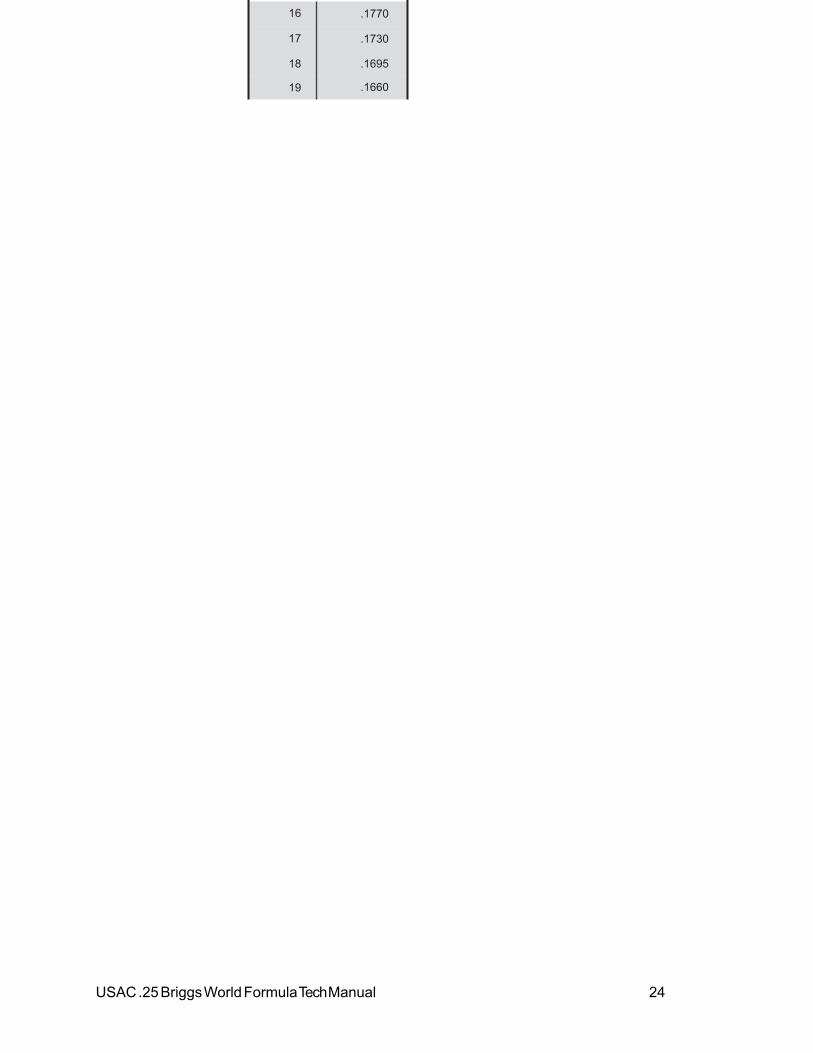
16 .1770
17 .1730
18 .1695
19 .1660

USAC .25 Briggs World Formula Tech Manual 25
20 .1610
No.
S i z e of Drill
21 .1590
22 .1570
23 .1540
24 .1520
25 .1495
26 .1470
27 .1440
28 .1405
29 .1360
30 .1285
31 .1200
32 .1160
33 .1130
34 .1110
35 .1100
36 .1065
37 .1040
38 .1015
39 .0995
40 .0980
No.
S i z e of Drill
41 .0960
42 .0935
43 .0890
44 .0860
45 .0820
46 .0810
47 .0785
48 .0760
49 .0730
50 .0700

USAC .25 Briggs World Formula Tech Manual 26
51 .0670
52 .0635
53 .0595
54 .0550
55 .0520
56 .0465
57 .0430
58 .0420

USAC .25 Briggs World Formula Tech Manual 27
Decimal Equivalents of Number Size Drills
59 60
.0410
.0400
No.
Size of Drill
61 .
62 .
63 .
64 .
65 .
66 .
67 .
68 .
69 .
70 .
71 .
72 .
73 .
74 .
75 .
76 .
77 .
78 .
79 .
80 .