brief 3ds max shaping tutorial - pc...
TRANSCRIPT
Brief 3ds max Shaping Tutorial
Written by Maestro Part1: Power Key Axe Shaft 1. Creation:
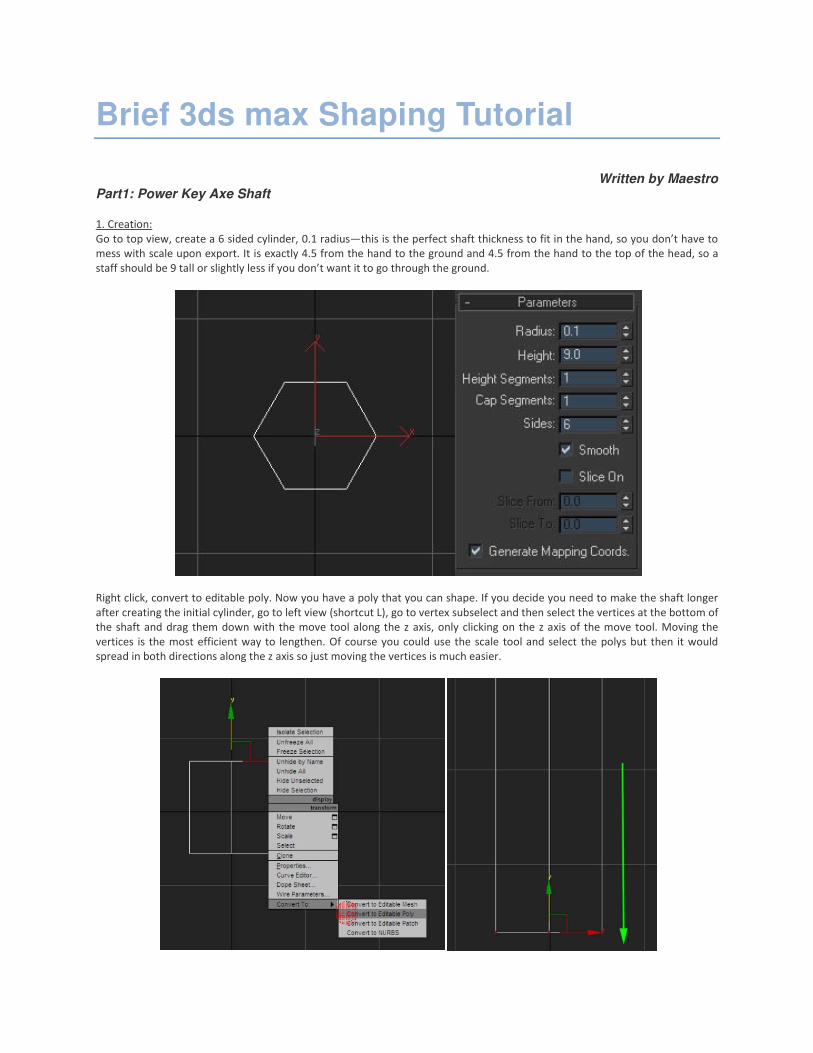
Go to top view, create a 6 sided cylinder, 0.1 radius—this is the perfect shaft thickness to fit in the hand, so you don’t have to
mess with scale upon export. It is exactly 4.5 from the hand to the ground and 4.5 from the hand to the top of the head, so a
staff should be 9 tall or slightly less if you don’t want it to go through the ground.
Right click, convert to editable poly. Now you have a poly that you can shape. If you decide you need to make the shaft longer
after creating the initial cylinder, go to left view (shortcut L), go to vertex subselect and then select the vertices at the bottom of
the shaft and drag them down with the move tool along the z axis, only clicking on the z axis of the move tool. Moving the
vertices is the most efficient way to lengthen. Of course you could use the scale tool and select the polys but then it would
spread in both directions along the z axis so just moving the vertices is much easier.

2. Basic Shaping:
Now let me recreate the power key axe, on the left will be the original and on the right the recreation we’ll be shaping. Look at
your 6 sided cylinder, the bottom and top of my cylinder are not equal to the original; so, I go to vertex subselect and move
them as I described above.
Now to get the shape of the original on the left I need another line intersecting the bottom of the shaft. Switch to poly select
and select your bottom polys. Right click and go to quickslice. Quickslice is an amazing tool because it will slice straight through
your model, both sides (cut which is above quickslice, only cuts the surface). Now click to the right or left of your model where
you want the slice to occur and a line should appear through the polys. Click again and it makes the slice. Right click to get out
of the quickslice tool so you don't accidentally make another slice.
Go back to vertex select. Select the bottom vertices, right click and go to weld but don't click on the word "weld" but the box
next to it. This is the best way to weld and the best way to extrude, because it's more precise and you have more options.
Increase the threshold until all the points collapse together, hit ok.
3. Advanced Shaping:
To get the cool shapely effect I have on the power key axe is really easy and doesn't require extruding at all but my favorite the
scaling tool (shortcut r). You'll only use the scaling tool, quickslice and the move tool for the next part.
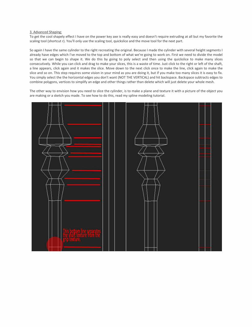
So again I have the same cylinder to the right recreating the original. Because I made the cylinder with several height segments I
already have edges which I've moved to the top and bottom of what we're going to work on. First we need to divide the model
so that we can begin to shape it. We do this by going to poly select and then using the quickslice to make many slices
consecutively. While you can click and drag to make your slices, this is a waste of time. Just click to the right or left of the shaft,
a line appears, click again and it makes the slice. Move down to the next click once to make the line, click again to make the
slice and so on. This step requires some vision in your mind as you are doing it, but if you make too many slices it is easy to fix.
You simply select the the horizontal edges you don't want (NOT THE VERTICAL) and hit backspace. Backspace subtracts edges to
combine polygons, vertices to simplify an edge and other things rather than delete which will just delete your whole mesh.
The other way to envision how you need to slice the cylinder, is to make a plane and texture it with a picture of the object you
are making or a sketch you made. To see how to do this, read my spline modeling tutorial.

Now go to vertex select. From the top select the second row of vertices from the slices you made. Rotate your view with arc
rotate (ctrl+r) just a little so you'll be able to see how you're going to expand with the scale tool, rightclick to get out of arc
rotate. With the vertices selected switch to scale tool ®. As you move your mouse over the scale tool different axis will light up.
Position your mouse on the bottom between the x and y so that only that outermost part of the bottom triangle is highlighted
(see pic) and drag it outward.
Because the next two rows should be the same you can select both rows of vertices and expand them together.
Now the line below the 2 we just did stays where it is. The next line down comes out sharply and the line two below it comes
out the same distance. So, select the line then hold crtl and select the other as well. Rotate up a little, switch to scale tool and
expand it out using the x and y axis at the same time as before.
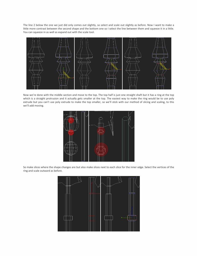
The line 2 below the one we just did only comes out slightly, so select and scale out slightly as before. Now I want to make a
little more contrast between the second shape and the bottom one so I select the line between them and squeeze it in a little.
You can squeeze in as well as expand out with the scale tool.
Now we’re done with the middle section and move to the top. The top half is just one straight shaft but it has a ring at the top
which is a straight protrusion and it actually gets smaller at the top. The easiest way to make the ring would be to use poly
extrude but you can’t use poly extrude to make the top smaller, so we’ll stick with our method of slicing and scaling, to this
we’ll add moving.
So make slices where the shape changes are but also make slices next to each slice for the inner edge. Select the vertices of the
ring and scale outward as before.
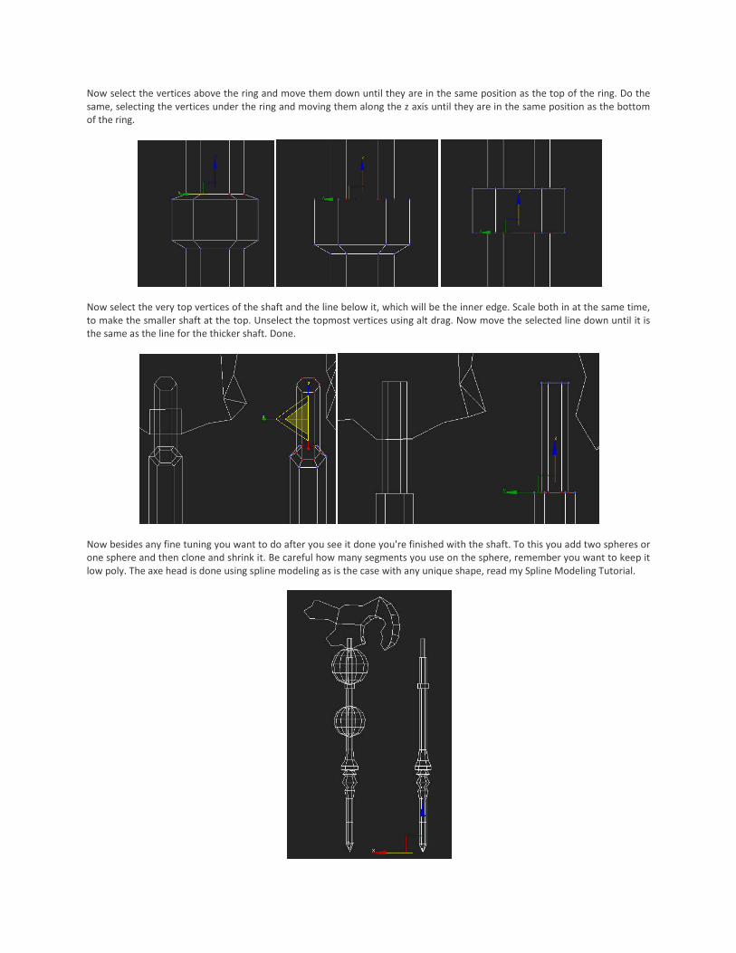
Now select the vertices above the ring and move them down until they are in the same position as the top of the ring. Do the
same, selecting the vertices under the ring and moving them along the z axis until they are in the same position as the bottom
of the ring.
Now select the very top vertices of the shaft and the line below it, which will be the inner edge. Scale both in at the same time,
to make the smaller shaft at the top. Unselect the topmost vertices using alt drag. Now move the selected line down until it is
the same as the line for the thicker shaft. Done.
Now besides any fine tuning you want to do after you see it done you're finished with the shaft. To this you add two spheres or
one sphere and then clone and shrink it. Be careful how many segments you use on the sphere, remember you want to keep it
low poly. The axe head is done using spline modeling as is the case with any unique shape, read my Spline Modeling Tutorial.
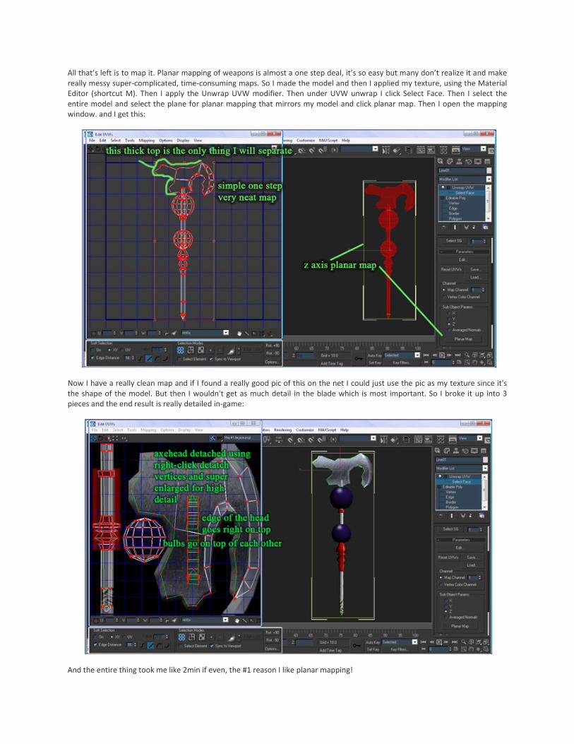
All that’s left is to map it. Planar mapping of weapons is almost a one step deal, it’s so easy but many don’t realize it and make
really messy super-complicated, time-consuming maps. So I made the model and then I applied my texture, using the Material
Editor (shortcut M). Then I apply the Unwrap UVW modifier. Then under UVW unwrap I click Select Face. Then I select the
entire model and select the plane for planar mapping that mirrors my model and click planar map. Then I open the mapping
window. and I get this:
Now I have a really clean map and if I found a really good pic of this on the net I could just use the pic as my texture since it's
the shape of the model. But then I wouldn't get as much detail in the blade which is most important. So I broke it up into 3
pieces and the end result is really detailed in-game:
And the entire thing took me like 2min if even, the #1 reason I like planar mapping!

Part 2: Making a Talon Clawed Staff
3. How to make talons using expand by polygon. For this we will use extrude by polygon, scale tool, weld and target weld. First
make a 6 sided cylinder, as with the first example, 1 height segment, 1 cap segment. Right click – convert to editable poly. Go to
left view and do a quick slice on the portion which will become the top claws, the cut should make squares of each poly (you
must switch to left view or right view to use the quickslice, you cannot just use arc rotate).
To make the talons you want to go to poly select (shortcut 4). Select the sides of the cylinder on the top portion you just sliced.
Go to extrude, select “extrude by polygon” not as a group or local, then select the value of extrusion that gives you roughly
cube shaped extensions.
Select the top polys of each talon extrusion but not the middle hexagon (see pic). Now right click and go to extrude and then
the box next to it, just as we did with weld. Select extrude by polygon so that each poly will extrude upward by itself. Increase
the extrusion amount until it is about equal with the bottom portion, hit ok.
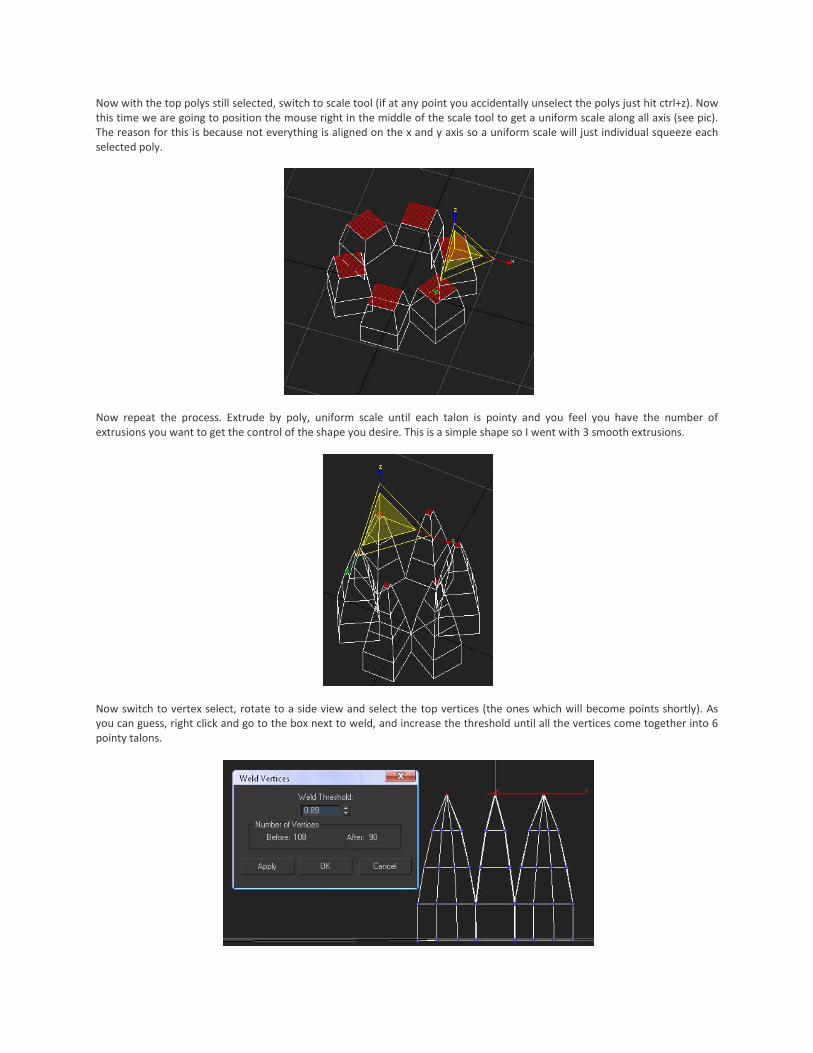
Now with the top polys still selected, switch to scale tool (if at any point you accidentally unselect the polys just hit ctrl+z). Now
this time we are going to position the mouse right in the middle of the scale tool to get a uniform scale along all axis (see pic).
The reason for this is because not everything is aligned on the x and y axis so a uniform scale will just individual squeeze each
selected poly.
Now repeat the process. Extrude by poly, uniform scale until each talon is pointy and you feel you have the number of
extrusions you want to get the control of the shape you desire. This is a simple shape so I went with 3 smooth extrusions.
Now switch to vertex select, rotate to a side view and select the top vertices (the ones which will become points shortly). As
you can guess, right click and go to the box next to weld, and increase the threshold until all the vertices come together into 6
pointy talons.

Now we still have to work out the rounded shape. Select the middle rows of vertices below the point and above the base (2
rows in my example). Rotate up and switch to scale tool. Now use the x-y axis scale to move the inside of each talon away from
the center. You want to move it a good way out to get the nice rounded shape. Don't mind the square bottom we'll get to that
in a minute just imagine the shape you want and don't mind the points we'll get to them in a minute too.
Now for the bottom. To make this easier to see in 2D I'll switch to smooth surface view (f3 to toggle between smooth and
wireframe, f2 to toggle highlighted faces, f4 to toggle edged faces). Switch to vertex select. For the next part we want to weld
all the vertices I have highlighted in red to the ones highlighted in green, to get rid of the boxy shape and make a smooth
transition from staff to head.
If you try to just use weld the vertices, they will weld to points across from them, because the distance across the talon is
shorter than the distance from the edge to the center. Even if this weren't true welding two points brings both points to the
median between them and we want to bring the outside points to the inside hexagon without changing the shape of your shaft.
So we'll use target weld. Right click and go to target weld. With target weld you click the point you want to move and then click
the vertex you want to move and then click the vertex you want to weld it to. So we want to click from outside to inside or the
middle points will move out to the outer.
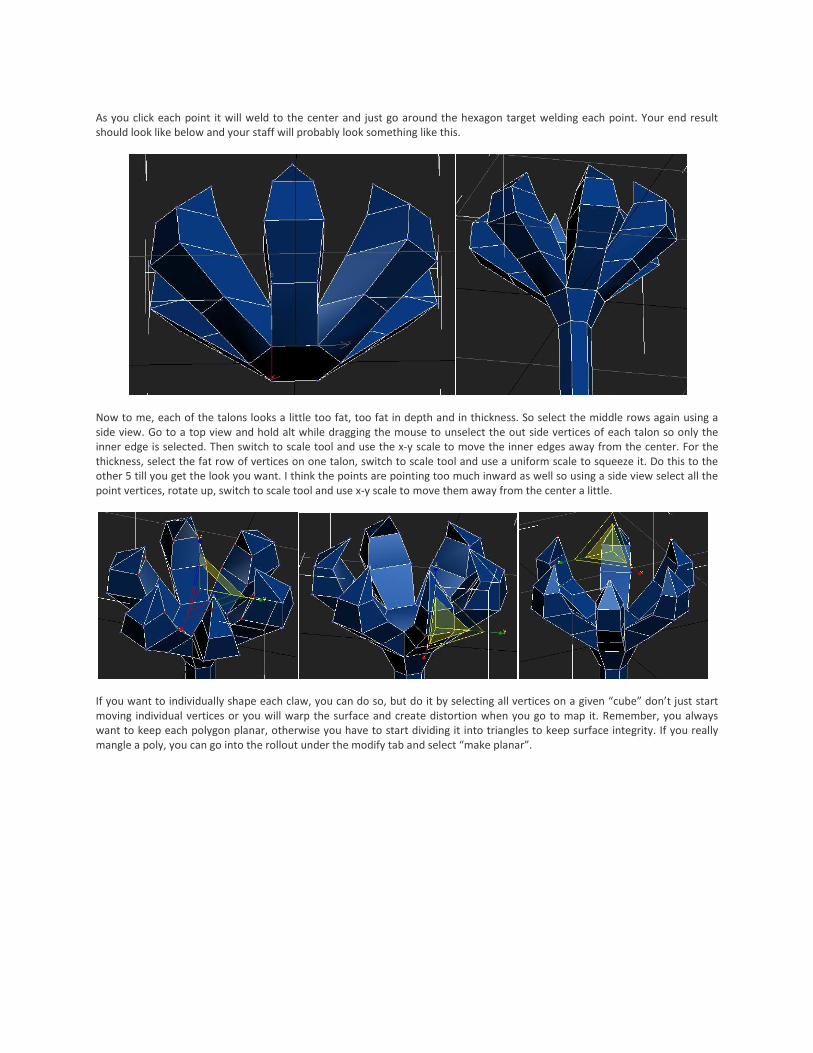
As you click each point it will weld to the center and just go around the hexagon target welding each point. Your end result
should look like below and your staff will probably look something like this.
Now to me, each of the talons looks a little too fat, too fat in depth and in thickness. So select the middle rows again using a
side view. Go to a top view and hold alt while dragging the mouse to unselect the out side vertices of each talon so only the
inner edge is selected. Then switch to scale tool and use the x-y scale to move the inner edges away from the center. For the
thickness, select the fat row of vertices on one talon, switch to scale tool and use a uniform scale to squeeze it. Do this to the
other 5 till you get the look you want. I think the points are pointing too much inward as well so using a side view select all the
point vertices, rotate up, switch to scale tool and use x-y scale to move them away from the center a little.
If you want to individually shape each claw, you can do so, but do it by selecting all vertices on a given “cube” don’t just start
moving individual vertices or you will warp the surface and create distortion when you go to map it. Remember, you always
want to keep each polygon planar, otherwise you have to start dividing it into triangles to keep surface integrity. If you really
mangle a poly, you can go into the rollout under the modify tab and select “make planar”.