brass 70/30 and incremental sheet forming process daniel fritzen
TRANSCRIPT
Brass 70/30 and Incremental Sheet Forming Process
Daniel Fritzen1,a, Anderson Daleffe2,b , Jovani Castelan3,c
and Lirio Schaeffer4,d 1, 2, 3
SATC Faculty, Criciúma - SC, Brazil,
4UFRGS, Department of Mines, Metallurgy and Materials Engineering, Porto Alegre – RS, Brazil.
Keywords: Forming Tool, Incremental Sheet Forming, Deformations, Brass Sheet 70/30.
Abstract. This work addresses through bibliographies and experiments the behavior of sheet brass
70/30 for Incremental Sheet Forming process, based on the parameters: wall angle (), step vertical
(ΔZ) and strategy tool path. Experiments are based on the method called Single Point Incremental
Forming - SPIF. For execution of practical tests, resources were used: software CAD / CAM, CNC
machining center with three axles, matrix incremental, incremental forming tool and a device press
sheets. Furthermore, measurement was made of the true deformation () and thickness (s1).
Practical tests have shown that the spiral machining strategy yielded a greater wall angle, compared
to the conventional strategy outline.
Introduction
The incremental forming sheet (ISF) is a recent process in the field of sheet forming when
compared to traditional processes, however, a technique is extremely flexible.
Given that this technology covers a wide and varied market, with singular characteristics, the
incremental forming adapts very well to some of the new market demands, such as agility in
manufacturing of prototypes and small series production of components and obtain parts that by
having a high geometrical complexity would become unfeasible by conventional methods [1].
The disadvantages cited in this process is the time required to perform the task and its geometric
and dimensional accuracy.
The main gains over a conventional process is the possibility to obtain greater deformation,
eliminate the need for mold / die and expand portfolio product companies that already have CNC
machine [2].
In this process, a small punch moves along a predefined path, locally deforming the sheet and
thus modeling the desired shape [3]. Because the deformation is caused by movement of the punch,
so only a small part of the sheet is actually formed at a given point in the process, since this punch
follows a defined path across the sheet [4].
The model is conformed to be generated from CAD1 files converted into three-dimensional
CAM2 files. The tool path is controlled by a program using CNC
3 technology [5].
The incremental forming is currently a promising process with regard to plastic forming of sheet
materials, and is not restricted solely to the shaping of sheet metal. More recent studies [6, 7, 8]
show the operation of incremental sheet forming in polymers.
Over the past three years the incremental forming process, a lot of work has focussed on the
understanding of deformation mechanisms, responses to the process of new materials, multi-stage
configuration for obtaining geometries with larger wall angles and broadening of its range of
applications [9].
1 Computer Aided Design
2 Computer Aided Manufacturing
3 Computer Numeric Control
Key Engineering Materials Vols. 554-557 (2013) pp 1419-1431© (2013) Trans Tech Publications, Switzerlanddoi:10.4028/www.scientific.net/KEM.554-557.1419
All rights reserved. No part of contents of this paper may be reproduced or transmitted in any form or by any means without the written permission of TTP,www.ttp.net. (ID: 177.2.0.139-10/04/13,12:44:46)
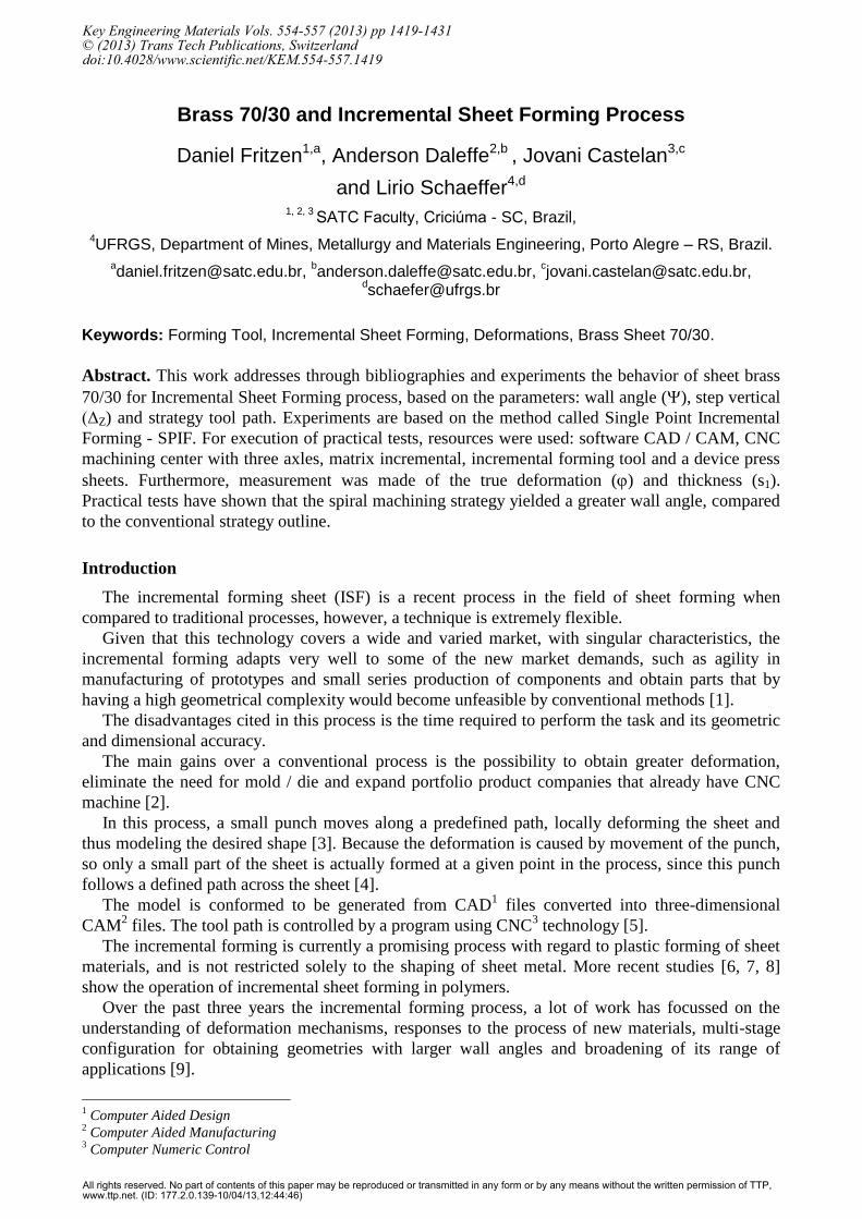
Within this diversification of applications studied, Silva [10] has proposed the fairings of a wind
turbine (Fig. 1 a) by means of ISF, while Jeswiet et al. [11] showed the manufacture of rapid
prototypes for the automotive industry (Fig. 1 b) and other areas (Fig. 1 c), achieving varied
geometric shapes by this process. In medical field, Castelan et al. [12] discuss the application of
incremental forming in making cranial prosthesis (Fig. 1 d) with titanium sheets.
Fig. 1: a) Wind Turbine and one of the experiments carried out by Silva [10]; b) Protector
automotive of heat / noise; c) Cavity solar oven; [11]; d) Results obtained in the manufacture of
cranial implant [12].
Besides applications in the ISF using CNC machines, there are studies submitted with the use of
industrial robots [13, 14, 15], plus some projects machines dedicated to this process [16, 17].
However, the use of robots and even dedicated machines does not compare to the number of
CNC machine tool (3 axles) used in most studies, which showed great efficiency to perform the
incrementally forming process [11, 18, 6, 19, 20], among others.
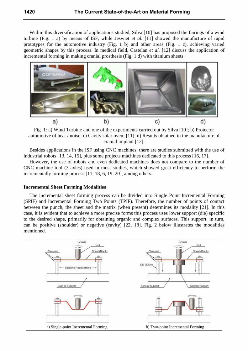
Incremental Sheet Forming Modalities
The incremental sheet forming process can be divided into Single Point Incremental Forming
(SPIF) and Incremental Forming Two Points (TPIF). Therefore, the number of points of contact
between the punch, the sheet and the matrix (when present) determines its modality [21]. In this
case, it is evident that to achieve a more precise forms this process uses lower support (die) specific
to the desired shape, primarily for obtaining organic and complex surfaces. This support, in turn,
can be positive (shoulder) or negative (cavity) [22, 18]. Fig. 2 below illustrates the modalities
mentioned.
a) Single-point Incremental Forming b) Two-point Incremental Forming
1420 The Current State-of-the-Art on Material Forming

c) Incremental forming with Asymmetrical Positive
Support
d) Incremental forming with Asymmetrical Negative
Support
Fig. 2: Incremental forming modalities. Adapted [23].
Specifically on the SPIF modality, used in this study, [24, 25] define the process as a flat metal
sheet, attached on a mobile device, which slides parallel to the axis Z. A ball nose tool controlled by
CNC, slides over the sheet, and gradually through vertical increments (ΔZ) in negatives Z plastically
deform the sheet, transforming it into a three-dimensional geometry, without the need for a support
matrix.
Castelan [23] which adds no lower support point, the shape of the end piece is determined only
by the displacement of the tool in three axes (X, Y, Z). The sheet is fixed to lateral a support which
maintains constant height relative to the base. Hussain [26] cited in their studies, that these fasteners
prevent the movement of the sheet during the process, culminating in its plastic deformation. Fig. 3
illustrates the process characteristics described by the authors.
Fig. 3: Single-point Incremental Forming (SPIF). Adapted [27].
In incremental forming there are values maximum angles wall () (65° on average) that allow
the plastic forming the material without causing fractures or at least a drastic decrease the sheet
thickness, causing a low mechanical resistance [28]. Be deemed to as wall angle () the angle
formed between the horizontal plane and the wall of the shaped part.
Key Engineering Materials Vols. 554-557 1421
For calculating the final thickness (s1) of the sheet after forming, is used to Sine Law, which is
applied the values of the wall angle () and the original thickness (s0) of the sheet, expressed by
equation 1.
s1 = s0·sinψ(90 - ) … [mm] (1)
Where s0 is the original thickness of the sheet, s1 is the sheet thickness measured in a given stage
of the forming process and the wall angle () of the sheet this same point.
Besides the original thickness (s0) of the sheet and vertical step (ΔZ) used this to some extent,
formation of the wall angle () is also influenced by the tool tip radius (Rt). This beam influences
the strength forming, where the larger the radius, the greater the strength [29].
Experimental Procedure
Based on the studies reported experiments in brass sheet 70/30 with 0.5 mm thickness were
developed with the aim of provide relevant information for prototyping and customization of
products made of this raw material, such as locks mirrors.
Eighteen (18) experiments were performed aiming at mainly set the wall angle () to sheet brass
70/30 with 0.5 mm thickness, altering step vertical (ΔZ) and machining strategy. The seven (7)
initial experiments were treated as preliminary and the other as final.
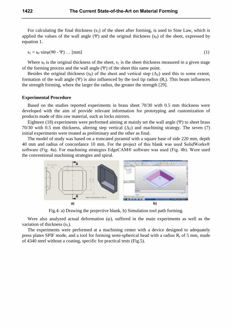
The model of study was based on a truncated pyramid with a square base of side 220 mm, depth
40 mm and radius of concordance 10 mm. For the project of this blank was used SolidWorks®
software (Fig. 4a). For machining strategies EdgeCAM® software was used (Fig. 4b). Were used
the conventional machining strategies and spiral.
Fig.4: a) Drawing the projective blank, b) Simulation tool path forming.
Were also analyzed actual deformation (), suffered in the main experiments as well as the
variation of thickness (s1).
The experiments were performed at a machining center with a device designed to adequately
press plates SPIF mode, and a tool for forming semi-spherical head with a radius Rt of 5 mm, made
of 4340 steel without a coating, specific for practical tests (Fig.5).
1422 The Current State-of-the-Art on Material Forming
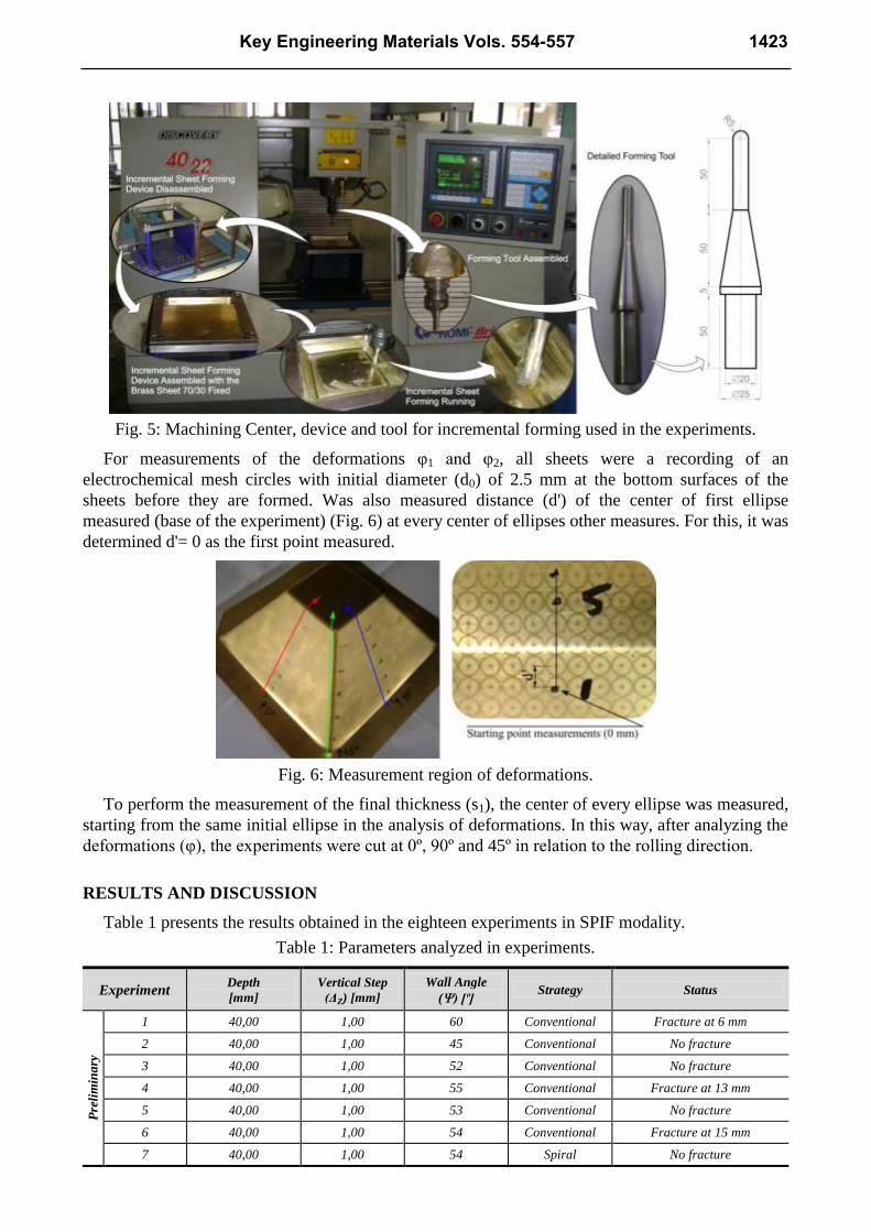
Fig. 5: Machining Center, device and tool for incremental forming used in the experiments.
For measurements of the deformations φ1 and φ2, all sheets were a recording of an
electrochemical mesh circles with initial diameter (d0) of 2.5 mm at the bottom surfaces of the
sheets before they are formed. Was also measured distance (d') of the center of first ellipse
measured (base of the experiment) (Fig. 6) at every center of ellipses other measures. For this, it was
determined d'= 0 as the first point measured.
Fig. 6: Measurement region of deformations.
To perform the measurement of the final thickness (s1), the center of every ellipse was measured,
starting from the same initial ellipse in the analysis of deformations. In this way, after analyzing the
deformations (φ), the experiments were cut at 0º, 90º and 45º in relation to the rolling direction.
RESULTS AND DISCUSSION
Table 1 presents the results obtained in the eighteen experiments in SPIF modality.
Table 1: Parameters analyzed in experiments.
Experiment Depth
[mm]
Vertical Step
(ΔZ) [mm]
Wall Angle
() [º] Strategy Status
Pre
lim
ina
ry
1 40,00 1,00 60 Conventional Fracture at 6 mm
2 40,00 1,00 45 Conventional No fracture
3 40,00 1,00 52 Conventional No fracture
4 40,00 1,00 55 Conventional Fracture at 13 mm
5 40,00 1,00 53 Conventional No fracture
6 40,00 1,00 54 Conventional Fracture at 15 mm
7 40,00 1,00 54 Spiral No fracture
Key Engineering Materials Vols. 554-557 1423

Fin
al
8 100,00 1,00 54 Spiral No fracture
9 100,00 1,00 55 Spiral No fracture
10 100,00 1,00 56 Spiral No fracture
11 100,00 1,00 60 Spiral Fracture at 14 mm
12 100,00 1,00 58 Spiral Fracture at 23 mm
13 100,00 1,00 59 Spiral Fracture at 12 mm
14 100,00 1,00 57 Spiral No fracture
15 100,00 0,50 57 Spiral No fracture
16 100,00 0,50 58 Spiral No fracture
17 100,00 0,50 56 Spiral No fracture
18 100,00 0,50 55 Spiral No fracture
According to the data in Table 1, observes a fracture in the experiments (in the 1, 4 and 6),
reaching a wall angle () minimum of 54° before reaching the designed depth (40.00 mm) (Fig. 7).
In this case, the fracture was due to the low thickness of the sheet in this region, causing a breakup
by pressure, a fact that usually occurs after the tool formed this point.
Fig. 7: Experiment 4; b) Enlarged detail of the fractured region. (: 55° | ΔZ: 1,00 mm).
The experiments 2, 3 and 5, where maximum wall angle () of achieved was 54°, reached
the projected depth (40.00 mm). However, due to the strategy of conventional machining, the point
where the tool always effected the increment vertical (ΔZ) has generated a deformation not projected
on the sheet (Fig. 8).
Fig. 8: a) Experiment 2, b) Entry point of the tool at Z; c) Mark the point of entry of the tool in Z on
the outside. (: 45° | ΔZ: 1,00 mm).
In the seventh experiment again was repeated wall angle () of 54 ° and the vertical step
(ΔZ) of 1.00 mm. However, strategy has changed to spiral of conformation.
In this new situation, no breaking of the sheet (Fig. 9) unlike the experiment 6. Another
detail to be emphasized is that on this new machining strategy, the sheet does not get branded input
tool in Z.
1424 The Current State-of-the-Art on Material Forming

Fig. 9: Experiment 7 cut out for the measurements of thicknesses and true strains. (: 54° | ΔZ:
1,00mm).
Due to the success of the experiment at 7, the experiments of 8 to 18, Final experiments were
considered, and executed with the strategy of forming spiral and 100 mm depth.
In experiments 8, 9, 10 (Fig. 10) and 14, where the vertical step (ΔZ) was 1.00 mm and in
experiments 15 to 18, where the vertical step (ΔZ) was 0.50 mm, there was no rupture of the sheet.
Fig. 10: Experiment 10 without fractures during ISF (: 56° | ΔZ: 1,00 mm).
In experiments 12 to 14, of the sheet breakage occurred (Fig. 11).
Fig. 11: Experiment 13. Fracture of the plate in enlarged detail (: 59° | ΔZ: 1,00 mm).
Key Engineering Materials Vols. 554-557 1425
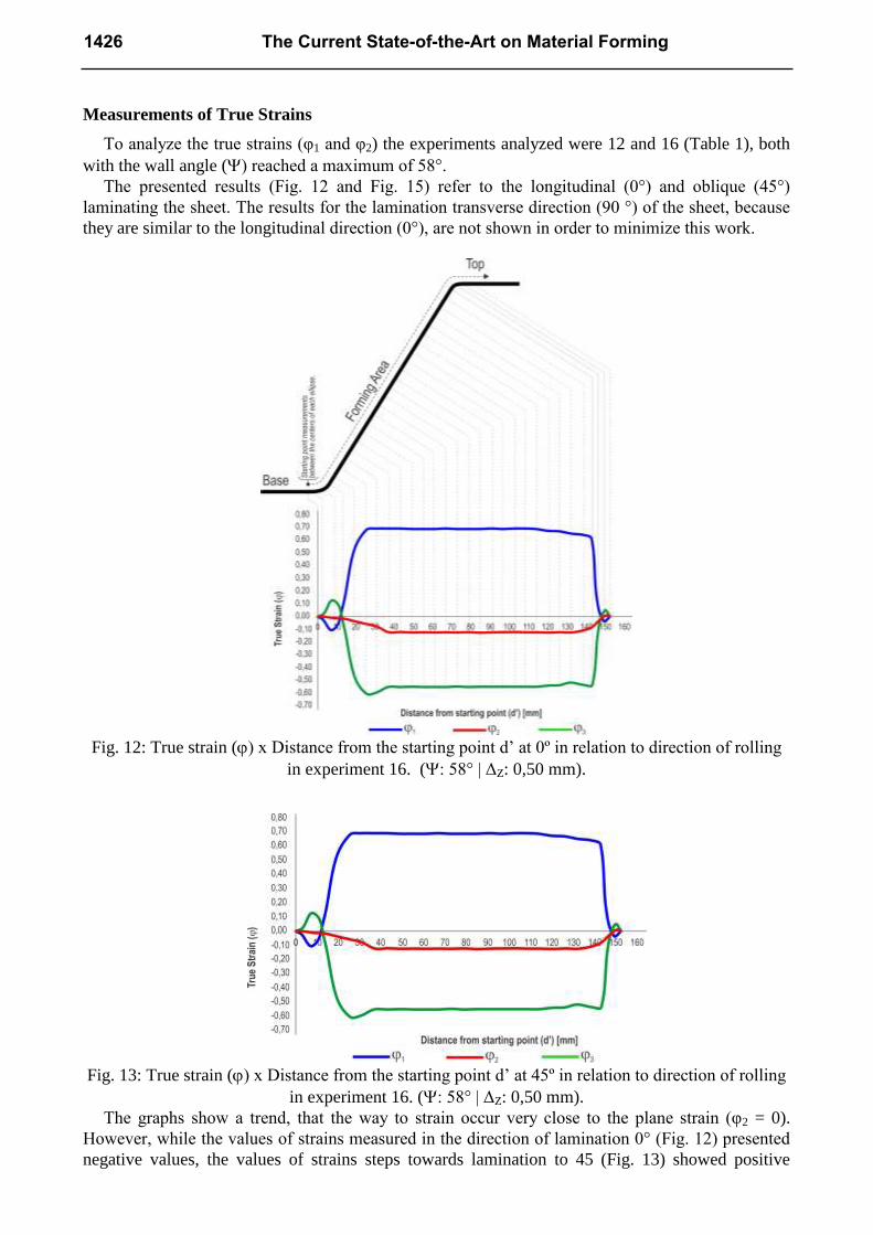
Measurements of True Strains
To analyze the true strains (φ1 and φ2) the experiments analyzed were 12 and 16 (Table 1), both
with the wall angle () reached a maximum of 58°.
The presented results (Fig. 12 and Fig. 15) refer to the longitudinal (0°) and oblique (45°)
laminating the sheet. The results for the lamination transverse direction (90 °) of the sheet, because
they are similar to the longitudinal direction (0°), are not shown in order to minimize this work.
Fig. 12: True strain () x Distance from the starting point d’ at 0º in relation to direction of rolling
in experiment 16. (: 58° | ΔZ: 0,50 mm).
Fig. 13: True strain () x Distance from the starting point d’ at 45º in relation to direction of rolling
in experiment 16. (: 58° | ΔZ: 0,50 mm).
The graphs show a trend, that the way to strain occur very close to the plane strain (φ2 = 0).
However, while the values of strains measured in the direction of lamination 0° (Fig. 12) presented
negative values, the values of strains steps towards lamination to 45 (Fig. 13) showed positive
1426 The Current State-of-the-Art on Material Forming

values and more expressive than the previous ones. This difference can be attributed to the
geometric form of the regions measures, regions where the rolling direction 0º are "flat" and the
measurement region in the rolling direction 45º is exactly on the "curve" of agreement between the
faces of the pyramid. Can still observe the maximum values strain of 0.68 towards 0º, and 0.48
towards 45º in relation to the rolling direction.
Fig. 14: True strain () x Distance from the starting point d’ at 0º in relation to direction of rolling
in experiment 12. (: 58° | ΔZ: 1,00 mm).
Fig. 15: True strain () x Distance from the starting point d’ at 45º in relation to direction of rolling
in experiment 12. (: 58° | ΔZ: 1,00 mm).
Similarly to the analysis of the of the experiment strains 16 are very close strain plane ( 2 = 0),
analysis of the deformations of the experiment 12 showed the same behavior. The maximum values
for deformation of 0.65 towards 0º, and 0.42 towards 45º in relation to the rolling direction.
Thickness Measurements after ISF
After the measurements of the deformations (φ1 and φ2), the experiments 12 and 16 (Table 1),
were cut in the three directions of lamination (0º, 45º and 90º) to measure the final thickness (s1) of
the sheet since measuring point d'. The Fig. 16 and Fig. 17 show the variation since thickness
measuring point d'.
Key Engineering Materials Vols. 554-557 1427
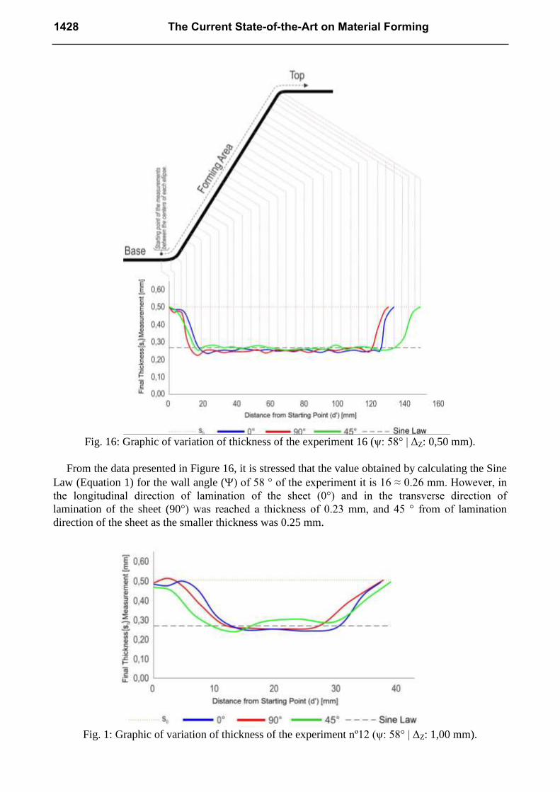
Fig. 16: Graphic of variation of thickness of the experiment 16 (ψ: 58° | ΔZ: 0,50 mm).
From the data presented in Figure 16, it is stressed that the value obtained by calculating the Sine
Law (Equation 1) for the wall angle () of 58 ° of the experiment it is 16 ≈ 0.26 mm. However, in
the longitudinal direction of lamination of the sheet (0°) and in the transverse direction of
lamination of the sheet (90°) was reached a thickness of 0.23 mm, and 45 ° from of lamination
direction of the sheet as the smaller thickness was 0.25 mm.
Fig. 1: Graphic of variation of thickness of the experiment nº12 (ψ: 58° | ΔZ: 1,00 mm).
1428 The Current State-of-the-Art on Material Forming
Just as in Experiment 16, also it was observed thicknesses (s1) below the limit established by
Sine Law (Eq. 1) for the wall angle () 58° (≈ 0.26 mm). For the of lamination longitudinal
direction of the sheet (0°) and 45° to the of lamination direction of the sheet was reached a thickness
of 0.24 mm and to the transverse direction of lamination of the sheet (90°) the smaller thickness was
0.25 mm.
Conclusion
By means of the realization of practical experiments, was evidenced the good applicability of
software CAD/CAM and CNC machining center in prototyping parts as from brass sheet 70/30 with
0.5 mm thickness using the incremental sheet forming process, SPIF modality.
According to the parameters used (Table 01) showed that the maximum wall angle () forming
of the sheet of brass 70/30 with 0.50 mm thickness varies according to the strategy conformation
and the vertical step (ΔZ).
It was found that by changing the conventional strategy for strategy spiral, a gain in the angle of
the wall () of 4° (Experiment 5 versus Experiment 14) without breaking the sheet.
Also it was proved that with decreasing vertical step (ΔZ) to 0.50 mm; there was a gain in the
angle of the wall () of 1°, concluding a product (Experimento16) of 100 mm depth without
breaking.
Analysis of strains In experiments performed, indicate a planar deformation (φ2 = 0), especially
in directions 0° and 90° in relation to of lamination direction of the sheet Toward the 45° of
lamination direction of the sheet, strains occur in directions greater than 0° and 90°, given that this
occurs exactly on the fillet radius of the conical faces of the piece.
Acknowledgments
The authors thank UFRGS/LDTM, CNPq and especially, Faculdade SATC for financial and
technical support in developing this project.
References
[1] L.F.S. Patrício, et al. A estampagem incremental como alternativa para a conformação em
pequenas séries. Corte & Conformação, Brazil, (2010) 26-44,
[2] U. Boff, et al. Estampagem Incremental: Método Alternativo para Fabricação de Protótipos e
Pequenos Lotes de Peas. Ferramental, Joinville, (2012) 13-17, ISSN ISSN 1981-240X.
[3] R. Malhotra, et al. Accumulative-DSIF strategy for enhancing process capabilities in
incremental forming. CIRP Annals - Manufacturing Technology, Evanston, IL, USA, (2012) 251 -
254. http://dx.doi.org/10.1016/j.cirp.2012.03.093.
[4] W.C. Emmens; G. Sebastiani; A.H.V.D Boogaard. The technology of Incremental Sheet
Forming–A brief review of the history. Journal of Materials Processing Technology, (2009)
[5] M. Bambach; G. Hirt; J. Ames. Modeling of Optimization Strategies in the Incremental CNC
Sheet Metal Forming Process. Institute of Materials Technology/Precision Forming (LWP),
Germany, p. 6. Saarland University. (2004)
[6] V. Franzen, et al. Single point incremental forming of PVC. Journal of Materials processing
technology, Dortmund, Germany, (2009) 462-469.
[7] T.A.F. Marques. Estampagem Incremental de Polímeros. Universidade Técnica de Lisboa.
Lisboa, (2010 ) p. 109.
Key Engineering Materials Vols. 554-557 1429

[8] P.A.F. Martins, et al. Single point incremental forming of polymers. CIRP Annals -
Manufacturing Technology, (2009) 229-232.
[9] L.F.S. Patrício. Estampagem Incremental de Chapas: Aplicação em Aço Comercial Automotivo.
PUC Minas. Belo Horizonte, (2012) p. 235.
[10] P.J.D. Silva. Estampagem Incremental Utilizada para Prototipagem de Carenagem de
Aerogerador. Programa de Pós-Graduação da Faculdade de Engenharia Mecânica da Universidade
de Brasília - UnB. Brasília - DF, (2011)p. 113.
[11] J. Jeswiet, et al. Asymmetric Single Point Incremental Forming of Sheet Metal. 5Katholieke
Universiteit Leuven, (2005) p. 27.
[12] J. Castelan, et al. Development of Cranial Implant Through Incremental Sheet Forming for
Medical Orthopedic Applications. International Journal of Materials Engineering an Technology, v.
4, n. 1, (2010) p. 63-80.
[13] L. Lamminen; T. Tuominen; S. Kivivuori. Incremental Sheet forming with an Industrial Robot.
Institute of Materials Engineering Australasia Ltd, (2005) 331-335.
[14] H. Meier. et al. Increasing the part accuracy in dieless robot-based incremental sheet metal
forming. CIRP Annals - Manufacturing Technology, (2009) 233-238.
[15] H. Meier; C. Magnus; V. Smukala. Impact of superimposed pressure on dieless incremental
sheet metal forming with two moving tools. CIRP Annals-Manufacturing Technology, (2011).
[16] J.M. Allwood; N.E. Houghton; K.P. Jackson. The Design of an incremental sheet forming
machine. Advanced Materials Research, (2005) 471 – 478.
[17] AMINO. Dieless NC Forming. Amino Corporation. Fujinomiya, (2006) p. 30.
[18] G. Hirt, et al. Flexible CNC Incremental Sheet Forming: Process Evaluation and Simulation.
Institute of Materials Technology/Precision Forming (LWP), Saarland University, Germany, (2005)
p. 12.
[19] G. Hussain; L. Gao. A novel method to test the thinning limits of sheet metals in negative
incremental forming. International Journal of Machine Tools & Manufacture, (2007) 419–435.
[20] G. Ambrogio, et al. Application of Incremental Forming process for high customised medical
product manufacturing. Journal of Materials Processing Technology, (2005) 156 - 162.
[21] A. Attanasio; E. Ceretti; C. Giardini. Optimization of tool path in two points incremental
forming. Journal of Materials Processing Technology, (2006) 409-412.
[22] J.M. Allwood, et al. A novel method for the rapid production of inexpensive dies and moulds
with surfaces made by incremental sheet forming. Proceedings of the Institution of Mechanical
Engineers, Part B: Journal of Engineering Manufacture (2006) 323-327.
[23] J. Castelan. Estampagem incremental do titânio comercialmente puro para aplicação em
implante craniano. UFRGS. Porto Alegre. (2010).
[24] G. Hussain, et al. A new formability indicator in single point incremental forming. Journal of
Materials Processing Technology, (2009) 4237–4242.
[25] J.R. Duflou, et al. Process window enhancement for single point incremental forming through
multi-step toolpaths. CIRP Annals - Manufacturing Technology, (2008) 253–256.
[26] G. Hussain, et al. A comparative study on the forming limits of an aluminum sheet-metal in
negative incremental forming. Journal of Materials Processing Technology, (2007) 94 – 98.
1430 The Current State-of-the-Art on Material Forming

[27] M.B. Silva; L.M. Alves; P.A.F Martins. Single point incremental forming of PVC:
Experimental findings and theoretical interpretation. European Journal of Mechanics A/Solids,
(2010) 557-566.
[28] J. Kopac; Z. Kampus. Incremental sheet metal forming on CNC milling machine-tool. Journal
of Materials Processing Technology. University of Ljubljana, Slovenia, (2005) 622–628.
[29] L.C. C. Cavaler; L. Schaeffer; F. Peruch. Variação de Espessura na Parede na Estampagem
Incremental com Ponto Simples para o Aço Inoxdável AISI 304L. 30 SENAFOR, Porto Alegre –
RS. (2010) 333-352.
Key Engineering Materials Vols. 554-557 1431