brands you trust. - mmcontrol.com valves gate crane® nibco milwaukee powell walworth stockham ......
TRANSCRIPT
brands you trust.
®
STOCKHAM® - Iron Valves
©Copyright 2013 CRANE ChemPharma & Energy
Distributed by: M&M Control Service, Inc. www.mmcontrol.com/stockham.php 800-876-0036 847-356-0566
2
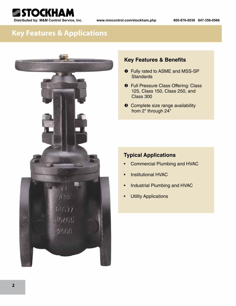
Key Features & Applications
Typical Applications
• Commercial Plumbing and HVAC
• Institutional HVAC
• Industrial Plumbing and HVAC
• Utility Applications
Key Features & Benefits
Fully rated to ASME and MSS-SP Standards
Full Pressure Class Offering: Class 125, Class 150, Class 250, and Class 300
Complete size range availability from 2" through 24"
Distributed by: M&M Control Service, Inc. www.mmcontrol.com/stockham.php 800-876-0036 847-356-0566
3
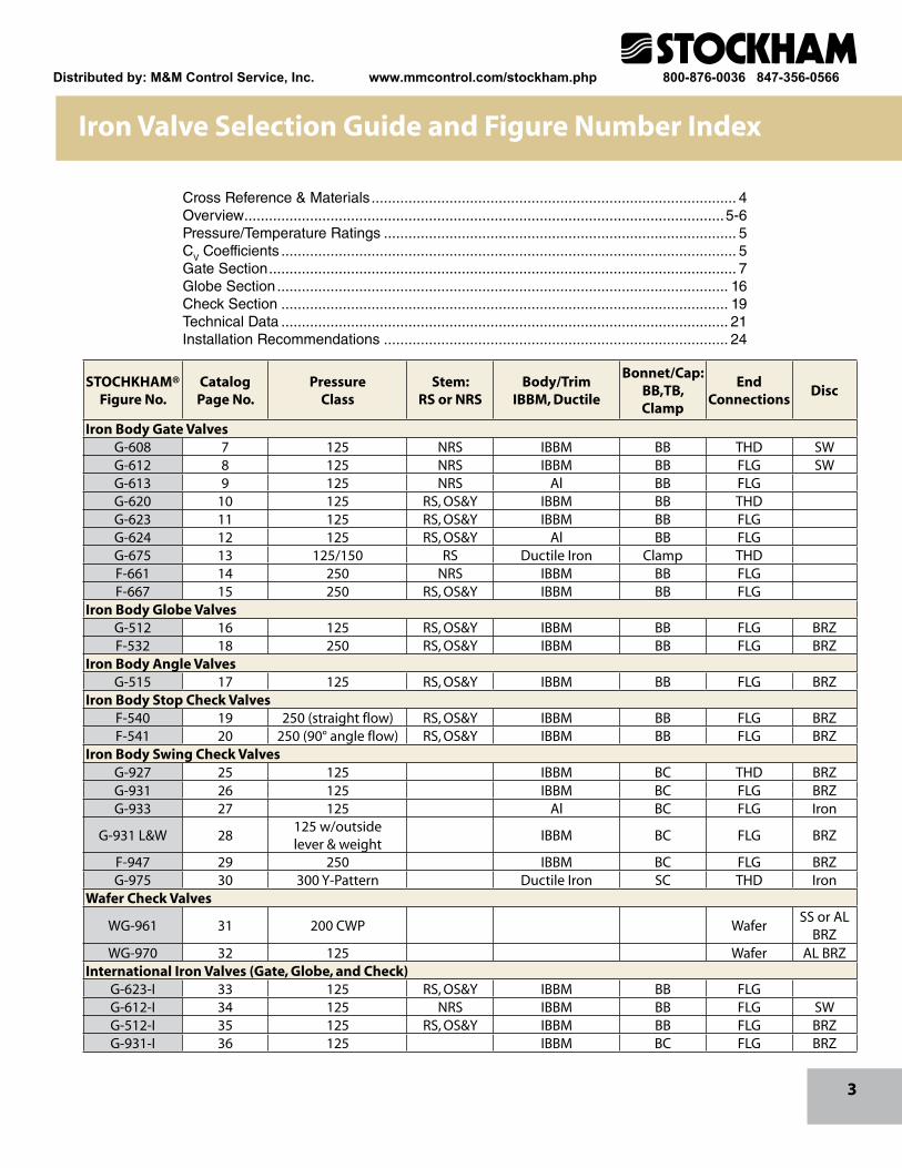
Cross Reference & Materials ......................................................................................... 4 Overview .....................................................................................................................5-6Pressure/Temperature Ratings ...................................................................................... 5CV Coefficients ............................................................................................................... 5Gate Section .................................................................................................................. 7Globe Section .............................................................................................................. 16Check Section ............................................................................................................. 19Technical Data ............................................................................................................. 21Installation Recommendations .................................................................................... 24
STOCHKHAM®Figure No.
CatalogPage No.
PressureClass
Stem:RS or NRS
Body/TrimIBBM, Ductile
Bonnet/Cap:BB,TB, Clamp
EndConnections
Disc
Iron Body Gate ValvesG-608 7 125 NRS IBBM BB THD SWG-612 8 125 NRS IBBM BB FLG SWG-613 9 125 NRS Al BB FLG G-620 10 125 RS, OS&Y IBBM BB THD G-623 11 125 RS, OS&Y IBBM BB FLG G-624 12 125 RS, OS&Y Al BB FLG G-675 13 125/150 RS Ductile Iron Clamp THD F-661 14 250 NRS IBBM BB FLGF-667 15 250 RS, OS&Y IBBM BB FLG
Iron Body Globe ValvesG-512 16 125 RS, OS&Y IBBM BB FLG BRZF-532 18 250 RS, OS&Y IBBM BB FLG BRZ
Iron Body Angle ValvesG-515 17 125 RS, OS&Y IBBM BB FLG BRZ
Iron Body Stop Check ValvesF-540 19 250 (straight flow) RS, OS&Y IBBM BB FLG BRZF-541 20 250 (90° angle flow) RS, OS&Y IBBM BB FLG BRZ
Iron Body Swing Check ValvesG-927 25 125 IBBM BC THD BRZG-931 26 125 IBBM BC FLG BRZG-933 27 125 Al BC FLG Iron
G-931 L&W 28125 w/outside lever & weight
IBBM BC FLG BRZ
F-947 29 250 IBBM BC FLG BRZG-975 30 300 Y-Pattern Ductile Iron SC THD Iron
Wafer Check Valves
WG-961 31 200 CWP WaferSS or AL
BRZWG-970 32 125 Wafer AL BRZ
International Iron Valves (Gate, Globe, and Check)G-623-I 33 125 RS, OS&Y IBBM BB FLG G-612-I 34 125 NRS IBBM BB FLG SWG-512-I 35 125 RS, OS&Y IBBM BB FLG BRZG-931-I 36 125 IBBM BC FLG BRZ
Iron Valve Selection Guide and Figure Number Index
Distributed by: M&M Control Service, Inc. www.mmcontrol.com/stockham.php 800-876-0036 847-356-0566
4
Cross Reference for Commonly Used Valves & Materials
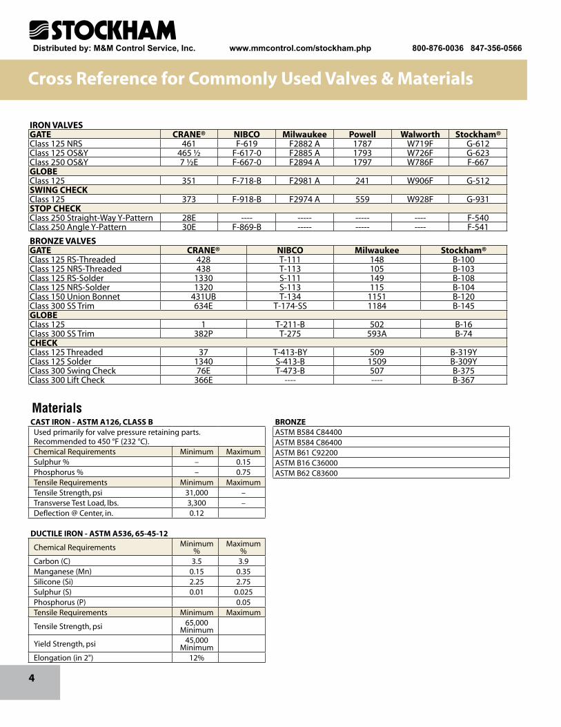
IRON VALVESGATE CRANE® NIBCO Milwaukee Powell Walworth Stockham®Class 125 NRS 461 F-619 F2882 A 1787 W719F G-612Class 125 OS&Y 465 ½ F-617-0 F2885 A 1793 W726F G-623Class 250 OS&Y 7 ½E F-667-0 F2894 A 1797 W786F F-667GLOBEClass 125 351 F-718-B F2981 A 241 W906F G-512SWING CHECKClass 125 373 F-918-B F2974 A 559 W928F G-931STOP CHECKClass 250 Straight-Way Y-Pattern 28E ---- ----- ----- ---- F-540Class 250 Angle Y-Pattern 30E F-869-B ----- ----- ---- F-541
BRONZE VALVESGATE CRANE® NIBCO Milwaukee Stockham®Class 125 RS-Threaded 428 T-111 148 B-100Class 125 NRS-Threaded 438 T-113 105 B-103Class 125 RS-Solder 1330 S-111 149 B-108Class 125 NRS-Solder 1320 S-113 115 B-104Class 150 Union Bonnet 431UB T-134 1151 B-120Class 300 SS Trim 634E T-174-SS 1184 B-145GLOBEClass 125 1 T-211-B 502 B-16Class 300 SS Trim 382P T-275 593A B-74CHECKClass 125 Threaded 37 T-413-BY 509 B-319YClass 125 Solder 1340 S-413-B 1509 B-309YClass 300 Swing Check 76E T-473-B 507 B-375Class 300 Lift Check 366E ---- ---- B-367
CAST IRON - ASTM A126, CLASS BUsed primarily for valve pressure retaining parts.Recommended to 450 °F (232 °C).Chemical Requirements Minimum MaximumSulphur % – 0.15Phosphorus % – 0.75Tensile Requirements Minimum MaximumTensile Strength, psi 31,000 –Transverse Test Load, lbs. 3,300 –Deflection @ Center, in. 0.12
DUCTILE IRON - ASTM A536, 65-45-12
Chemical Requirements Minimum %
Maximum %
Carbon (C) 3.5 3.9Manganese (Mn) 0.15 0.35Silicone (Si) 2.25 2.75Sulphur (S) 0.01 0.025Phosphorus (P) 0.05Tensile Requirements Minimum Maximum
Tensile Strength, psi 65,000 Minimum
Yield Strength, psi 45,000 Minimum
Elongation (in 2") 12%
BRONZEASTM B584 C84400ASTM B584 C86400 ASTM B61 C92200ASTM B16 C36000ASTM B62 C83600
Materials
Distributed by: M&M Control Service, Inc. www.mmcontrol.com/stockham.php 800-876-0036 847-356-0566
5
Overview
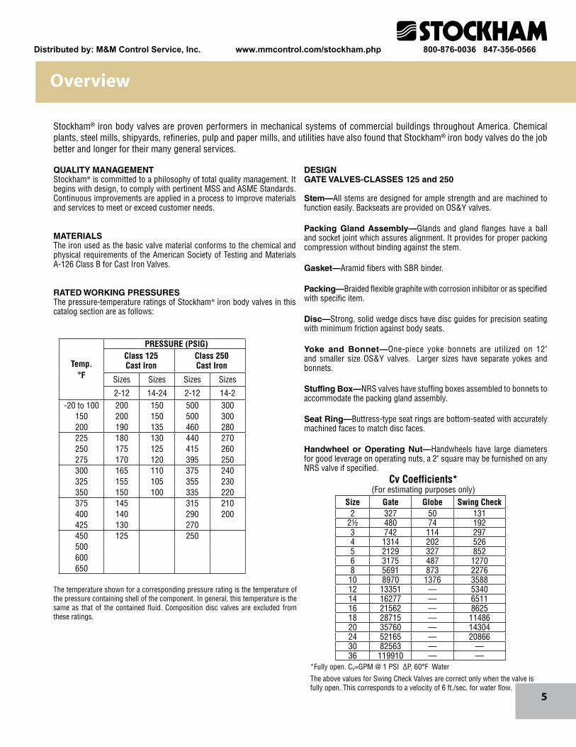
Stockham® iron body valves are proven performers in mechanical systems of commercial buildings throughout America. Chemical plants, steel mills, shipyards, refineries, pulp and paper mills, and utilities have also found that Stockham® iron body valves do the job better and longer for their many general services.
QUALITY MANAGEMENTStockham® is committed to a philosophy of total quality management. It begins with design, to comply with pertinent MSS and ASME Standards. Continuous improvements are applied in a process to improve materials and services to meet or exceed customer needs.
MATERIALSThe iron used as the basic valve material conforms to the chemical and physical requirements of the American Society of Testing and Materials A-126 Class B for Cast Iron Valves.
RATED WORKING PRESSURESThe pressure-temperature ratings of Stockham® iron body valves in this catalog section are as follows:
The temperature shown for a corresponding pressure rating is the temperature of the pressure containing shell of the component. In general, this temperature is the same as that of the contained fluid. Composition disc valves are excluded from these ratings.
DESIGNGATE VALVES-CLASSES 125 and 250
Stem—All stems are designed for ample strength and are machined to function easily. Backseats are provided on OS&Y valves.
Packing Gland Assembly—Glands and gland flanges have a ball and socket joint which assures alignment. It provides for proper packing compression without binding against the stem.
Gasket—Aramid fibers with SBR binder.
Packing—Braided flexible graphite with corrosion inhibitor or as specified with specific item.
Disc—Strong, solid wedge discs have disc guides for precision seating with minimum friction against body seats.
Yoke and Bonnet—One-piece yoke bonnets are utilized on 12" and smaller size OS&Y valves. Larger sizes have separate yokes and bonnets.
Stuffing Box—NRS valves have stuffing boxes assembled to bonnets to accommodate the packing gland assembly.
Seat Ring—Buttress-type seat rings are bottom-seated with accurately machined faces to match disc faces.
Handwheel or Operating Nut—Handwheels have large diameters for good leverage on operating nuts, a 2" square may be furnished on any NRS valve if specified.
*Fully open. CV=GPM @ 1 PSI ∆P, 60°F Water
The above values for Swing Check Valves are correct only when the valve is fully open. This corresponds to a velocity of 6 ft./sec. for water flow.
Size Gate Globe Swing Check2 327 50 131
2½ 480 74 1923 742 114 2974 1314 202 5265 2129 327 8526 3175 487 12708 5691 873 227610 8970 1376 358812 13351 — 534014 16277 — 651116 21562 — 862518 28715 — 1148620 35760 — 1430424 52165 — 2086630 82563 — —36 119910 — —
Cv Coefficients*(For estimating purposes only)
Temp.°F
PRESSURE (PSIG)Class 125 Cast Iron
Class 250 Cast Iron
Sizes Sizes Sizes Sizes
2-12 14-24 2-12 14-2-20 to 100 200 150 500 300
150 200 150 500 300200 190 135 460 280225 180 130 440 270250 175 125 415 260275 170 120 395 250300 165 110 375 240325 155 105 355 230350 150 100 335 220375 145 315 210400 140 290 200425 130 270450 125 250500600650
Distributed by: M&M Control Service, Inc. www.mmcontrol.com/stockham.php 800-876-0036 847-356-0566
6
Overview
Yoke Bushing—Yoke bushings on OS&Y valves have Acme threads for stem engagement; and handwheels fit snugly over bushings. Handwheels are securely locked to yoke bushings with locknuts. A bolted yoke cap secures the yoke bushing to the yoke.
Body—Body sections are evenly distributed for maximum strength. Dimensions and drilling of end flanges of cast iron valves conform to the ASME Standard B16.1 for Classes 125 and 250 Cast Iron Flanges. Face-to-face dimensions comply with ASME Standard B16.10.
DESIGN: GLOBE AND ANGLE VALVES-OUTSIDE SCREW AND YOKE-CLASSES 125 and 250
Stem—Stems are machined with Acme threads which fully engage the yoke bushing threads at all times.
Packing Gland Assembly—Glands and gland flanges have a ball and socket joint which assures alignment and proper packing compression.
Packing—Braided flexible graphite with corrosion inhibitor or as specified with specific item.
Backseat Bushing—Bushings are threaded into bonnets, providing beveled seats for backseating on stem shoulders.
Disc—Bronze discs are furnished in Class 125 and 250 globe and angle valves, which are regrindable. Disc nuts thread into disc. The Class 250 nonreturn stop-check valve conforms to ASME boiler codes and utilizes a dashpot and piston design to cushion the disc action.
Yoke Bonnet—One-piece yoke bonnets are fastened to bodies with capscrews.
Seat Rings—Seat rings are bottom-seated and are readily renewable.
Handwheel—Handwheels have large diameters for ample leverage.
Yoke Bushing—Accurate Acme threads engage stem threads. Set screws fasten yoke bushings to yoke.
Body—Bodies are designed with uniform sections evenly distributed for maximum strength. Dimensions and drilling of end flanges on flanged valves conform to the ASME Standard B16.1 for Classes 125 and 250 Cast Iron Flanges. Face-to-face dimensions comply with the ASME Standard B16.10.
DESIGN:SWING CHECK VALVES-CLASSES 125 and 250
Cap—Caps are bolted to bodies.
Hinge—Hinges are precisely drilled for assembly with discs.
Hinge Pin—Pins are located by side plugs, screwed into bodies.
Disc—Disc faces are accurately machined for tight seal with seat rings.
Seat Ring—Buttress design of renewable seat rings provides bottom seating and good strength.
Body—Dimensions and drilling of end flanges on flanged valves conform to ASME Standard B16.1 for Classes 125 and 250 Cast Iron Flanges. Face-to-face dimensions comply with ASME B16.10.
Figure G-931 L&W: Swing Check valves sized 2"-12" come standard with an adjustable lever arm which can be orientated in any position in 15° increments. These valves can be installed in horizontal lines or in vertical lines with upward flow. 14"-24" valves must be specified at the time of inquiry and order with the installation orientation for horizontal or vertical-upward flow.
ACCESSORIES—Stockham® iron body valves may be furnished with motor operators, gearings, bypasses, floorstands, extension stems, lever and weight attachment or other accessories.
MARKING—Numerals indicate the size and pressure class. Cast arrows indicate direction of flow on check, globe, and angle valves.
TESTING AND INSPECTION—Before shipment, each valve is individually tested under pressure for soundness of castings and tight closure to MSS Standards.
FINISH—External cast iron parts are coated with a durable black finish.
WEIGHTS AND DIMENSIONS—Dimensions and weights shown in this catalog section are furnished for estimating purposes only and are subject to change without notice. It is our intent to maintain basic dimensional requirements of accepted standards.
Distributed by: M&M Control Service, Inc. www.mmcontrol.com/stockham.php 800-876-0036 847-356-0566
7
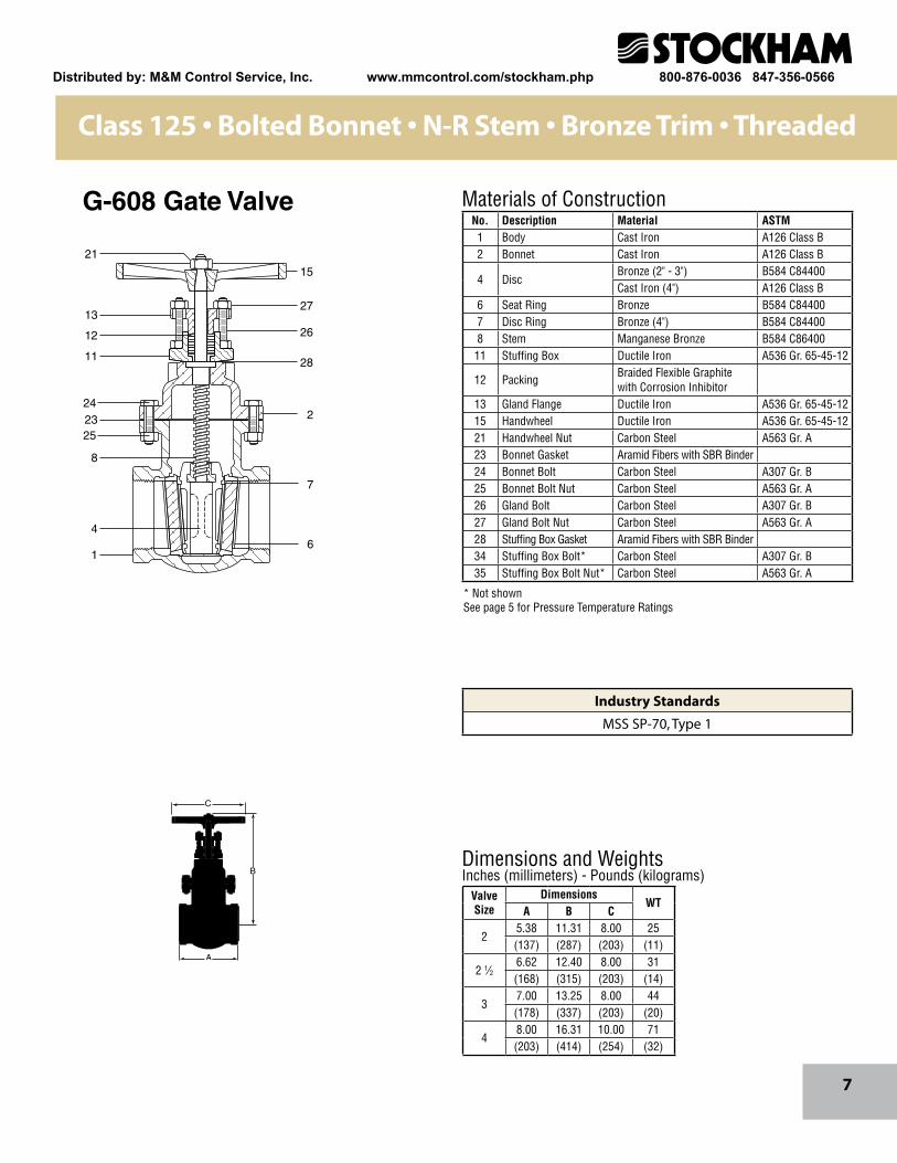
Class 125 • Bolted Bonnet • N-R Stem • Bronze Trim • Threaded
Dimensions and WeightsInches (millimeters) - Pounds (kilograms)
Materials of Construction
* Not shownSee page 5 for Pressure Temperature Ratings
8
23
4
1
2
7
6
21
15
27
26
2811
13
12
24
25
B
A
C
No. Description Material ASTM1 Body Cast Iron A126 Class B2 Bonnet Cast Iron A126 Class B
4 DiscBronze (2" - 3") B584 C84400Cast Iron (4") A126 Class B
6 Seat Ring Bronze B584 C844007 Disc Ring Bronze (4") B584 C844008 Stem Manganese Bronze B584 C8640011 Stuffing Box Ductile Iron A536 Gr. 65-45-12
12 PackingBraided Flexible Graphite with Corrosion Inhibitor
13 Gland Flange Ductile Iron A536 Gr. 65-45-1215 Handwheel Ductile Iron A536 Gr. 65-45-1221 Handwheel Nut Carbon Steel A563 Gr. A23 Bonnet Gasket Aramid Fibers with SBR Binder24 Bonnet Bolt Carbon Steel A307 Gr. B25 Bonnet Bolt Nut Carbon Steel A563 Gr. A26 Gland Bolt Carbon Steel A307 Gr. B27 Gland Bolt Nut Carbon Steel A563 Gr. A28 Stuffing Box Gasket Aramid Fibers with SBR Binder34 Stuffing Box Bolt* Carbon Steel A307 Gr. B35 Stuffing Box Bolt Nut* Carbon Steel A563 Gr. A
ValveSize
DimensionsWT
A B C
25.38 11.31 8.00 25(137) (287) (203) (11)
2 1⁄26.62 12.40 8.00 31(168) (315) (203) (14)
37.00 13.25 8.00 44(178) (337) (203) (20)
48.00 16.31 10.00 71(203) (414) (254) (32)
G-608 Gate Valve
Industry Standards
MSS SP-70, Type 1
Distributed by: M&M Control Service, Inc. www.mmcontrol.com/stockham.php 800-876-0036 847-356-0566
8
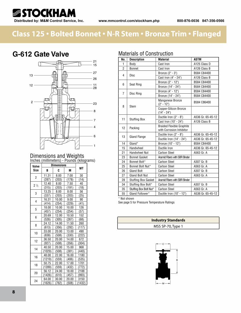
Class 125 • Bolted Bonnet • N-R Stem • Bronze Trim • Flanged
M
C
B
2115
13
12
2
27
26
1128
23
8
7
4
6
1
Dimensions and WeightsInches (millimeters) - Pounds (kilograms)
Materials of ConstructionNo. Description Material ASTM1 Body Cast Iron A125 Class D2 Bonnet Cast Iron A126 Class B
4 DiscBronze (2" - 3") B584 C84400Cast Iron (4" - 24") A126 Class B
6 Seat RingBronze (2" - 12") B584 C84400Bronze (14" - 24") B584 C84400
7 Disc RingBronze (4" - 12") B584 C84400Bronze (14" - 24") B584 C84400
8 Stem
Manganese Bronze (2" - 12") B584 C86400
Copper-Silicon Bronze (14" - 24")
11 Stuffing BoxDuctile Iron (2" - 8") A536 Gr. 65-45-12Cast Iron (10" - 24") A126 Class B
12 Packing Braided Flexible Graphite with Corrosion Inhibitor
13 Gland FlangeDuctile Iron (2" - 8") A536 Gr. 65-45-12Ductile Iron (14" - 24") A536 Gr. 65-45-12
14 Gland* Bronze (10" - 12") B584 C8440015 Handwheel Ductile Iron A536 Gr. 65-45-1221 Handwheel Nut Carbon Steel A563 Gr. A23 Bonnet Gasket Aramid Fibers with SBR Binder24 Bonnet Bolt* Carbon Steel A307 Gr. B25 Bonnet Bolt Nut* Carbon Steel A563 Gr. A26 Gland Bolt Carbon Steel A307 Gr. B27 Gland Bolt Nut Carbon Steel A563 Gr. A28 Stuffing Box Gasket Aramid Fibers with SBR Binder34 Stuffing Box Bolt* Carbon Steel A307 Gr. B35 Stuffing Box Bolt Nut* Carbon Steel A563 Gr. A55 Gland Follower* Ductile Iron (10" - 12") A536 Gr. 65-45-12
ValveSize
DimensionsWT
B C M
211.31 8.00 7.00 30(287) (203) (178) (14)
2 1⁄212.40 8.00 7.50 40(315) (203) (191) (18)
313.25 8.00 8.00 56(337) (203) (203) (25)
416.31 10.00 9.00 90(414) (254) (229) (41)
518.00 10.00 10.00 126(457) (254) (254) (57)
620.69 12.00 10.50 152(526) (305) (267) (68)
824.12 14.00 11.50 260(613) (356) (292) (117)
1033.00 20.00 13.00 490(838) (508) (330) (222)
1236.50 20.00 14.00 672(927) (508) (356) (304)
1440.50 20.00 15.00 968(1029) (508) (381) (440)
1648.00 22.00 16.00 1180(1219) (559) (406) (535)
1850.75 22.00 17.00 1701(1289) (559) (432) (772)
2056.12 24.00 18.00 2188(1426) (610) (457) (993)
2464.00 30.00 20.00 3150(1626) (762) (508) (1432)
G-612 Gate Valve
* Not shownSee page 5 for Pressure Temperature Ratings
Industry Standards
MSS SP-70, Type 1
Distributed by: M&M Control Service, Inc. www.mmcontrol.com/stockham.php 800-876-0036 847-356-0566
9
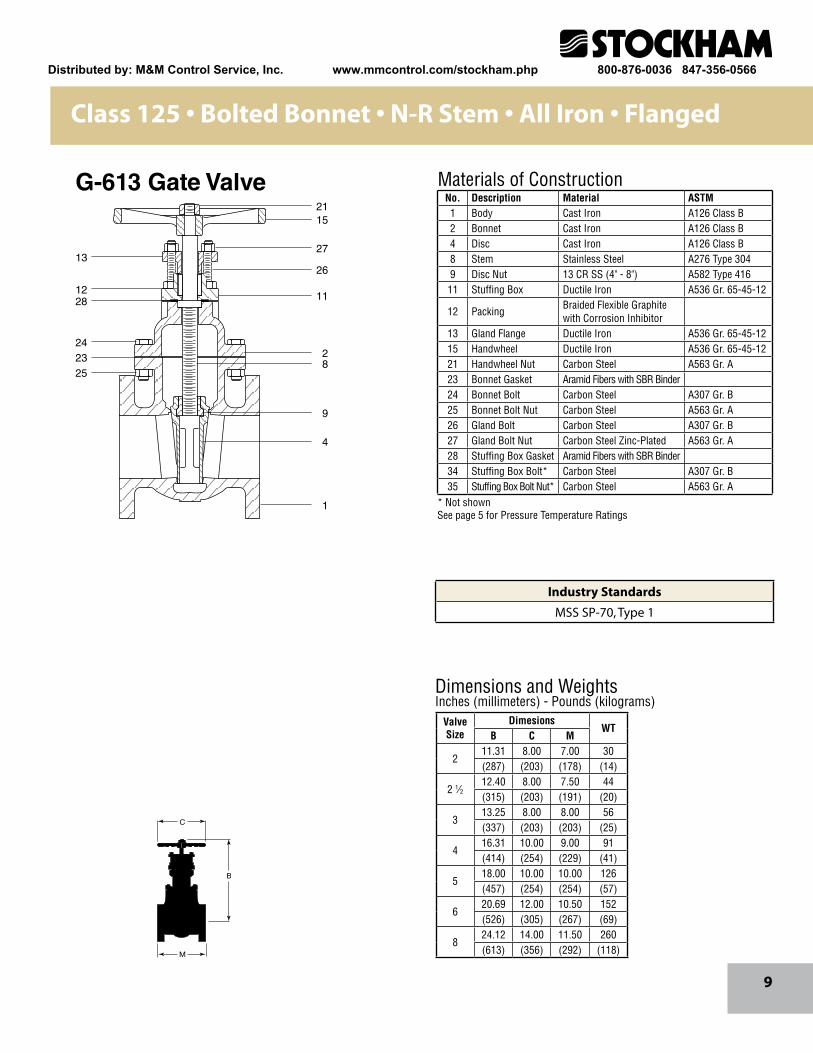
Class 125 • Bolted Bonnet • N-R Stem • All Iron • Flanged
M
C
B
2115
27
26
11
28
9
4
1
13
1228
242325
Dimensions and WeightsInches (millimeters) - Pounds (kilograms)
Materials of ConstructionNo. Description Material ASTM1 Body Cast Iron A126 Class B2 Bonnet Cast Iron A126 Class B4 Disc Cast Iron A126 Class B8 Stem Stainless Steel A276 Type 3049 Disc Nut 13 CR SS (4" - 8") A582 Type 41611 Stuffing Box Ductile Iron A536 Gr. 65-45-12
12 PackingBraided Flexible Graphite with Corrosion Inhibitor
13 Gland Flange Ductile Iron A536 Gr. 65-45-1215 Handwheel Ductile Iron A536 Gr. 65-45-1221 Handwheel Nut Carbon Steel A563 Gr. A23 Bonnet Gasket Aramid Fibers with SBR Binder24 Bonnet Bolt Carbon Steel A307 Gr. B25 Bonnet Bolt Nut Carbon Steel A563 Gr. A26 Gland Bolt Carbon Steel A307 Gr. B27 Gland Bolt Nut Carbon Steel Zinc-Plated A563 Gr. A28 Stuffing Box Gasket Aramid Fibers with SBR Binder34 Stuffing Box Bolt* Carbon Steel A307 Gr. B35 Stuffing Box Bolt Nut* Carbon Steel A563 Gr. A
Valve Size
DimesionsWT
B C M
211.31 8.00 7.00 30(287) (203) (178) (14)
2 1⁄212.40 8.00 7.50 44(315) (203) (191) (20)
313.25 8.00 8.00 56(337) (203) (203) (25)
416.31 10.00 9.00 91(414) (254) (229) (41)
518.00 10.00 10.00 126(457) (254) (254) (57)
620.69 12.00 10.50 152(526) (305) (267) (69)
824.12 14.00 11.50 260(613) (356) (292) (118)
G-613 Gate Valve
Industry Standards
MSS SP-70, Type 1
* Not shownSee page 5 for Pressure Temperature Ratings
Distributed by: M&M Control Service, Inc. www.mmcontrol.com/stockham.php 800-876-0036 847-356-0566
10
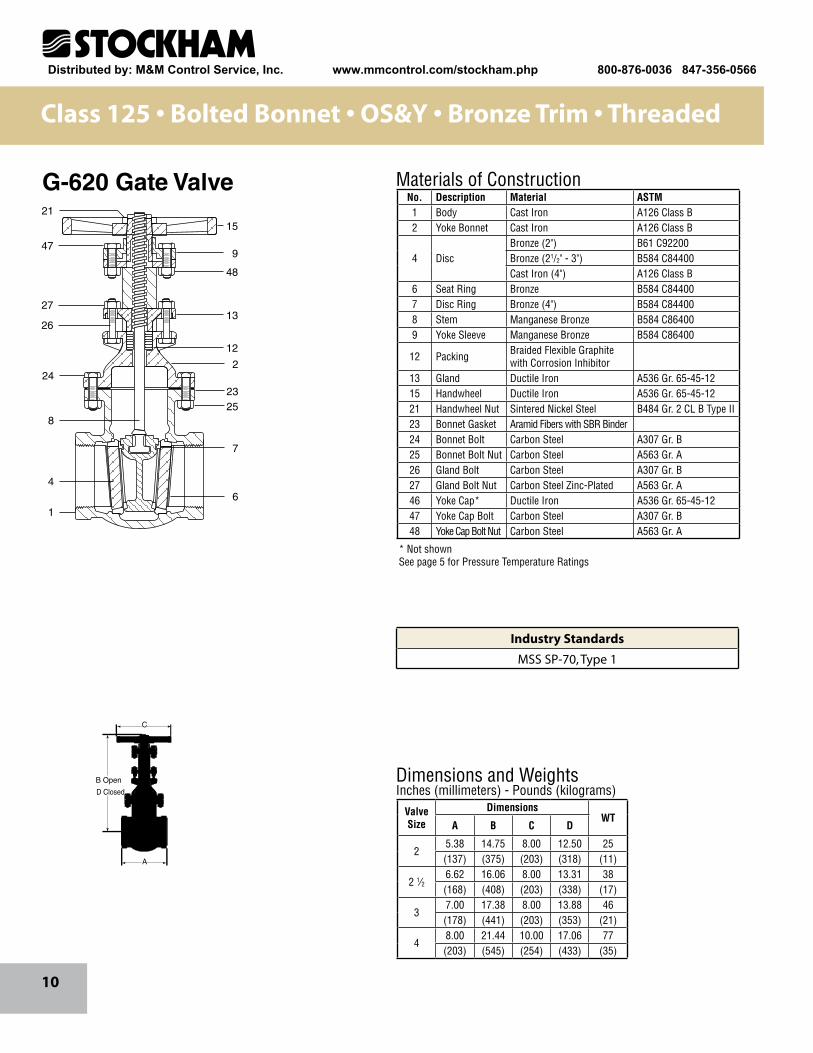
Class 125 • Bolted Bonnet • OS&Y • Bronze Trim • Threaded
Dimensions and WeightsInches (millimeters) - Pounds (kilograms)
Materials of Construction
2325
8
24
4
1
2
7
6
2115
9
48
13
12
26
27
47
B Open
A
C
D Closed
No. Description Material ASTM1 Body Cast Iron A126 Class B2 Yoke Bonnet Cast Iron A126 Class B
4 DiscBronze (2") B61 C92200Bronze (21/2" - 3") B584 C84400Cast Iron (4") A126 Class B
6 Seat Ring Bronze B584 C844007 Disc Ring Bronze (4") B584 C844008 Stem Manganese Bronze B584 C864009 Yoke Sleeve Manganese Bronze B584 C86400
12 Packing Braided Flexible Graphite with Corrosion Inhibitor
13 Gland Ductile Iron A536 Gr. 65-45-1215 Handwheel Ductile Iron A536 Gr. 65-45-1221 Handwheel Nut Sintered Nickel Steel B484 Gr. 2 CL B Type II23 Bonnet Gasket Aramid Fibers with SBR Binder24 Bonnet Bolt Carbon Steel A307 Gr. B25 Bonnet Bolt Nut Carbon Steel A563 Gr. A26 Gland Bolt Carbon Steel A307 Gr. B27 Gland Bolt Nut Carbon Steel Zinc-Plated A563 Gr. A46 Yoke Cap* Ductile Iron A536 Gr. 65-45-1247 Yoke Cap Bolt Carbon Steel A307 Gr. B48 Yoke Cap Bolt Nut Carbon Steel A563 Gr. A
ValveSize
DimensionsWT
A B C D
25.38 14.75 8.00 12.50 25(137) (375) (203) (318) (11)
2 1⁄26.62 16.06 8.00 13.31 38(168) (408) (203) (338) (17)
37.00 17.38 8.00 13.88 46(178) (441) (203) (353) (21)
48.00 21.44 10.00 17.06 77(203) (545) (254) (433) (35)
G-620 Gate Valve
* Not shownSee page 5 for Pressure Temperature Ratings
Industry Standards
MSS SP-70, Type 1
Distributed by: M&M Control Service, Inc. www.mmcontrol.com/stockham.php 800-876-0036 847-356-0566
11
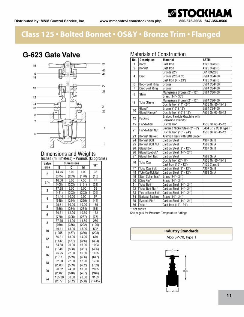
Class 125 • Bolted Bonnet • OS&Y • Bronze Trim • Flanged
21
4746
27
26
2
25
4
1
15
948
13
12
2423
8
7
6
M
C
BOpen
Materials of Construction
Dimensions and WeightsInches (millimeters) - Pounds (kilograms)
No. Description Material ASTM1 Body Cast Iron A126 Class B2 Bonnet Cast Iron A126 Class B
4 DiscBronze (2") B61 C92200Bronze (21/2"& 3") B584 C84400Cast Iron (4" - 24") A126 Class B
6 Body Seat Ring Bronze B584 C844007 Disc Seat Ring Bronze B584 C84400
8 StemManganese Bronze (2" - 12") B584 C86400Brass (14" - 36")
9 Yoke SleeveManganese Bronze (2" - 12") B584 C86400Ductile Iron (14" - 24") A536 Gr. 65-45-12
10Gland* Bronze (10" & 12") B584 C84400Gland Flange* Ductile Iron (10" & 12") A536 Gr. 65-45-12
12 Packing Braided Flexible Graphite with Corrosion Inhibitor
15 Handwheel Ductile Iron A536 Gr. 65-45-12
21 Handwheel NutSintered Nickel Steel (2" - 8") B484 Gr. 2 CL B Type IIDuctile Iron (10" - 24") A536 Gr. 65-45-12
23 Bonnet Gasket Aramid Fibers with SBR Binder24 Bonnet Bolt Carbon Steel A307 Gr. B25 Bonnet Bolt Nut Carbon Steel A563 Gr. A26 Gland Bolt Carbon Steel (2" - 12") A307 Gr. B26 Gland Eyebolt* Carbon Steel (14" - 24") 27 Gland Bolt Nut Carbon Steel A563 Gr. A
46 Yoke CapDuctile Iron (2" - 8") A536 Gr. 65-45-12Cast Iron (10" - 12") A126 Class B
47 Yoke Cap Bolt Carbon Steel (2" - 12") A307 Gr. B48 Yoke Cap Bolt Nut Carbon Steel (2" - 12") A563 Gr. A49 Stem Collar Seat* Brass (14" - 24") 50 Disc Pin* Brass (14" - 24") 51 Yoke Bolt* Carbon Steel (14" - 24")52 Yoke Bolt Nut* Carbon Steel (14" - 24")53 Yoke to Bonnet Bolt* Carbon Steel (14" - 24")54 Backseat Bushing* Brass (14" - 24")55 Eyebolt Pin* Carbon Steel (14" - 24")56 Yoke* Cast Iron (14" - 24")
ValveSize
DimensionsWT
B C M
214.75 8.00 7.00 33(375) (203) (178) (15)
2 1⁄216.06 8.00 7.50 47(408) (203) (191) (21)
317.38 8.00 8.00 58(441) (203) (203) (26)
421.44 10.00 9.00 97(545) (254) (229) (44)
525.81 10.00 10.00 135(656) (254) (254) (61)
630.31 12.00 10.50 162(770) (305) (267) (73)
837.75 14.00 11.50 280(959) (356) (292) (126)
1049.41 18.00 13.00 502(1255) (457) (330) (228)
1256.81 18.00 14.00 670(1442) (457) (356) (304)
1464.88 20.00 15.00 1093(1648) (508) (381) (496)
1675.25 22.00 16.00 1425(1911) (559) (406) (647)
18 82.00 22.00 17.00 1738(2083) (559) (432) (789)
20 90.62 24.00 18.00 2085(2302) (610) (457) (946)
24105.38 30.00 20.00 3183(2677) (762) (508) (1445)
G-623 Gate Valve
* Not shownSee page 5 for Pressure Temperature Ratings
Industry Standards
MSS SP-70, Type 1
Distributed by: M&M Control Service, Inc. www.mmcontrol.com/stockham.php 800-876-0036 847-356-0566
12
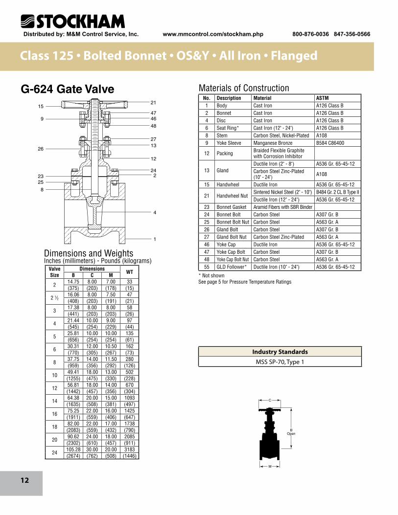
Class 125 • Bolted Bonnet • OS&Y • All Iron • Flanged
21
4746
48
2713
12
242
4
1
23
26
15
9
25
8
Dimensions and WeightsInches (millimeters) - Pounds (kilograms)
M
C
BOpen
Materials of ConstructionNo. Description Material ASTM1 Body Cast Iron A126 Class B2 Bonnet Cast Iron A126 Class B4 Disc Cast Iron A126 Class B6 Seat Ring* Cast Iron (12" - 24") A126 Class B8 Stem Carbon Steel, Nickel-Plated A1089 Yoke Sleeve Manganese Bronze B584 C86400
12 Packing Braided Flexible Graphite with Corrosion Inhibitor
13 GlandDuctile Iron (2" - 8") A536 Gr. 65-45-12Carbon Steel Zinc-Plated (10" - 24") A108
15 Handwheel Ductile Iron A536 Gr. 65-45-12
21 Handwheel NutSintered Nickel Steel (2" - 10") B484 Gr. 2 CL B Type IIDuctile Iron (12" - 24") A536 Gr. 65-45-12
23 Bonnet Gasket Aramid Fibers with SBR Binder24 Bonnet Bolt Carbon Steel A307 Gr. B25 Bonnet Bolt Nut Carbon Steel A563 Gr. A26 Gland Bolt Carbon Steel A307 Gr. B27 Gland Bolt Nut Carbon Steel Zinc-Plated A563 Gr. A46 Yoke Cap Ductile Iron A536 Gr. 65-45-1247 Yoke Cap Bolt Carbon Steel A307 Gr. B48 Yoke Cap Bolt Nut Carbon Steel A563 Gr. A55 GLD Follower* Ductile Iron (10" - 24") A536 Gr. 65-45-12Valve
SizeDimensions WTB C M
2 14.75 8.00 7.00 33(375) (203) (178) (15)
2 1⁄216.06 8.00 7.50 47(408) (203) (191) (21)
3 17.38 8.00 8.00 58(441) (203) (203) (26)
4 21.44 10.00 9.00 97(545) (254) (229) (44)
5 25.81 10.00 10.00 135(656) (254) (254) (61)
6 30.31 12.00 10.50 162(770) (305) (267) (73)
8 37.75 14.00 11.50 280(959) (356) (292) (126)
10 49.41 18.00 13.00 502(1255) (475) (330) (228)
12 56.81 18.00 14.00 670(1442) (457) (356) (304)
14 64.38 20.00 15.00 1093(1635) (508) (381) (497)
16 75.25 22.00 16.00 1425(1911) (559) (406) (647)
18 82.00 22.00 17.00 1738(2083) (559) (432) (790)
20 90.62 24.00 18.00 2085(2302) (610) (457) (911)
24 105.28 30.00 20.00 3183(2674) (762) (508) (1446)
G-624 Gate Valve
* Not shownSee page 5 for Pressure Temperature Ratings
Industry Standards
MSS SP-70, Type 1
Distributed by: M&M Control Service, Inc. www.mmcontrol.com/stockham.php 800-876-0036 847-356-0566
13
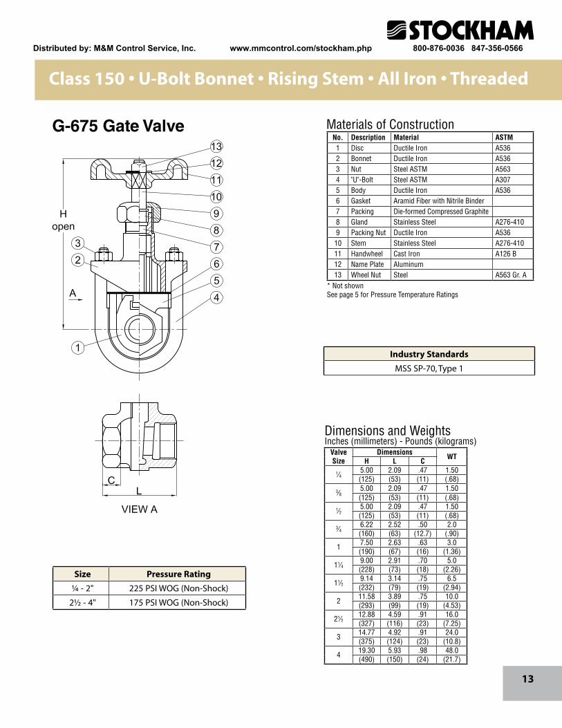
Class 150 • U-Bolt Bonnet • Rising Stem • All Iron • Threaded
Dimensions and WeightsInches (millimeters) - Pounds (kilograms)
Materials of ConstructionNo. Description Material ASTM1 Disc Ductile Iron A5362 Bonnet Ductile Iron A5363 Nut Steel ASTM A5634 "U"-Bolt Steel ASTM A3075 Body Ductile Iron A5366 Gasket Aramid Fiber with Nitrile Binder7 Packing Die-formed Compressed Graphite8 Gland Stainless Steel A276-4109 Packing Nut Ductile Iron A53610 Stem Stainless Steel A276-41011 Handwheel Cast Iron A126 B12 Name Plate Aluminum13 Wheel Nut Steel A563 Gr. A
ValveSize
Dimensions WTH L C 1⁄4
5.00 2.09 .47 1.50(125) (53) (11) (.68)
3⁄85.00 2.09 .47 1.50(125) (53) (11) (.68)
1⁄25.00 2.09 .47 1.50(125) (53) (11) (.68)
3⁄46.22 2.52 .50 2.0(160) (63) (12.7) (.90)
1 7.50 2.63 .63 3.0(190) (67) (16) (1.36)
11⁄49.00 2.91 .70 5.0(228) (73) (18) (2.26)
11⁄29.14 3.14 .75 6.5(232) (79) (19) (2.94)
2 11.58 3.89 .75 10.0(293) (99) (19) (4.53)
21⁄212.88 4.59 .91 16.0(327) (116) (23) (7.25)
3 14.77 4.92 .91 24.0(375) (124) (23) (10.8)
4 19.30 5.93 .98 48.0(490) (150) (24) (21.7)
G-675 Gate Valve
Size Pressure Rating
¼ - 2" 225 PSI WOG (Non-Shock)
2½ - 4" 175 PSI WOG (Non-Shock)
* Not shownSee page 5 for Pressure Temperature Ratings
Industry Standards
MSS SP-70, Type 1
Distributed by: M&M Control Service, Inc. www.mmcontrol.com/stockham.php 800-876-0036 847-356-0566
14
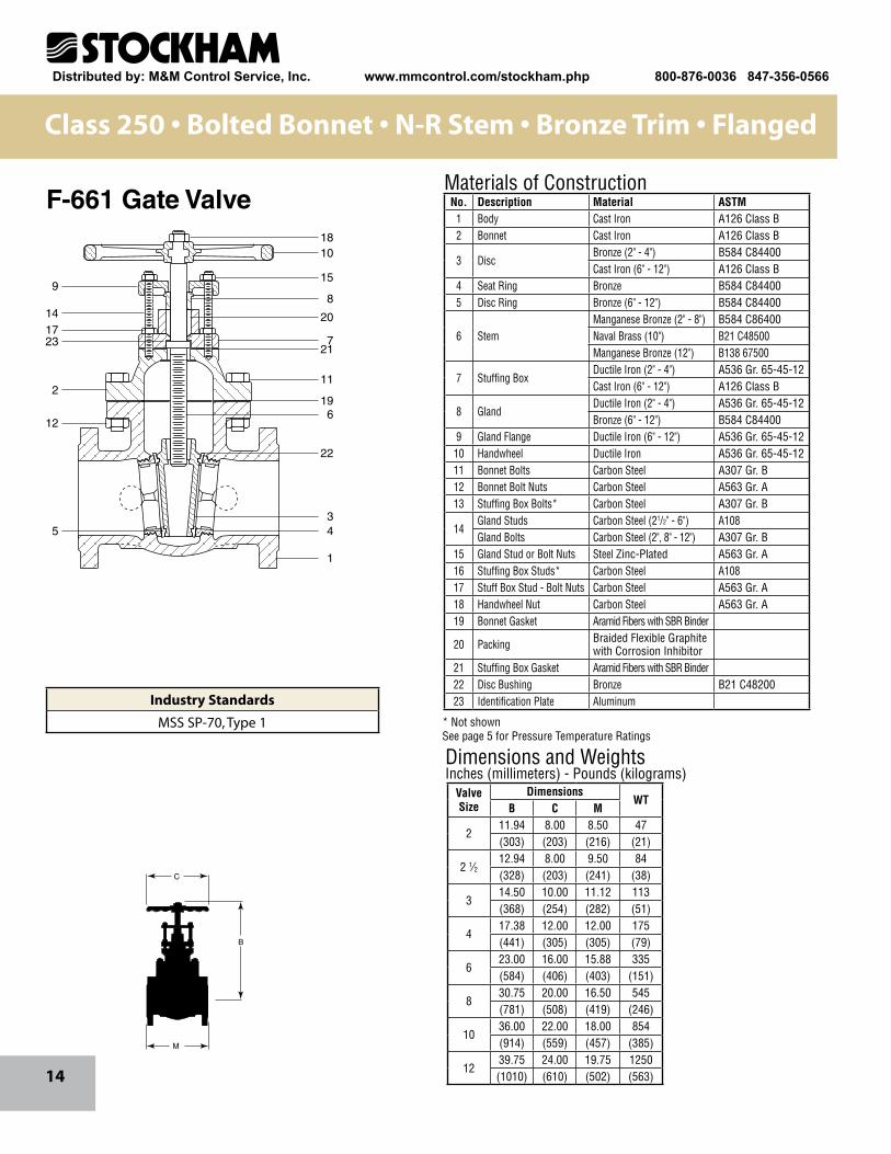
Class 250 • Bolted Bonnet • N-R Stem • Bronze Trim • Flanged
1810
15
8
20
721
11
196
22
34
1
9
141723
2
12
5
Dimensions and WeightsInches (millimeters) - Pounds (kilograms)
M
C
B
Materials of ConstructionNo. Description Material ASTM
1 Body Cast Iron A126 Class B2 Bonnet Cast Iron A126 Class B
3 DiscBronze (2" - 4") B584 C84400Cast Iron (6" - 12") A126 Class B
4 Seat Ring Bronze B584 C844005 Disc Ring Bronze (6" - 12") B584 C84400
6 StemManganese Bronze (2" - 8") B584 C86400Naval Brass (10") B21 C48500Manganese Bronze (12") B138 67500
7 Stuffing BoxDuctile Iron (2" - 4") A536 Gr. 65-45-12Cast Iron (6" - 12") A126 Class B
8 GlandDuctile Iron (2" - 4") A536 Gr. 65-45-12Bronze (6" - 12") B584 C84400
9 Gland Flange Ductile Iron (6" - 12") A536 Gr. 65-45-1210 Handwheel Ductile Iron A536 Gr. 65-45-1211 Bonnet Bolts Carbon Steel A307 Gr. B12 Bonnet Bolt Nuts Carbon Steel A563 Gr. A13 Stuffing Box Bolts* Carbon Steel A307 Gr. B
14Gland Studs Carbon Steel (21/2" - 6") A108Gland Bolts Carbon Steel (2", 8" - 12") A307 Gr. B
15 Gland Stud or Bolt Nuts Steel Zinc-Plated A563 Gr. A16 Stuffing Box Studs* Carbon Steel A10817 Stuff Box Stud - Bolt Nuts Carbon Steel A563 Gr. A18 Handwheel Nut Carbon Steel A563 Gr. A19 Bonnet Gasket Aramid Fibers with SBR Binder
20 Packing Braided Flexible Graphite with Corrosion Inhibitor
21 Stuffing Box Gasket Aramid Fibers with SBR Binder22 Disc Bushing Bronze B21 C4820023 Identification Plate Aluminum
ValveSize
DimensionsWT
B C M
211.94 8.00 8.50 47(303) (203) (216) (21)
2 1⁄212.94 8.00 9.50 84(328) (203) (241) (38)
314.50 10.00 11.12 113(368) (254) (282) (51)
417.38 12.00 12.00 175(441) (305) (305) (79)
623.00 16.00 15.88 335(584) (406) (403) (151)
830.75 20.00 16.50 545(781) (508) (419) (246)
1036.00 22.00 18.00 854(914) (559) (457) (385)
1239.75 24.00 19.75 1250(1010) (610) (502) (563)
F-661 Gate Valve
* Not shownSee page 5 for Pressure Temperature Ratings
Industry Standards
MSS SP-70, Type 1
Distributed by: M&M Control Service, Inc. www.mmcontrol.com/stockham.php 800-876-0036 847-356-0566
15
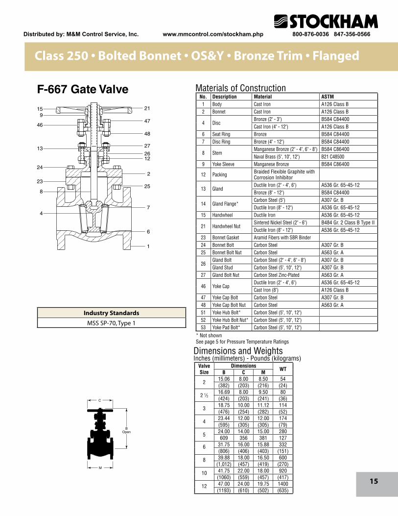
Class 250 • Bolted Bonnet • OS&Y • Bronze Trim • Flanged
BOpen
C
M
21
47
48
27
2612
2
25
7
6
1
9
46
13
24
23
8
4
15
Dimensions and WeightsInches (millimeters) - Pounds (kilograms)
Materials of ConstructionNo. Description Material ASTM
1 Body Cast Iron A126 Class B2 Bonnet Cast Iron A126 Class B
4 DiscBronze (2" - 3") B584 C84400Cast Iron (4" - 12") A126 Class B
6 Seat Ring Bronze B584 C844007 Disc Ring Bronze (4" - 12") B584 C84400
8 StemManganese Bronze (2" - 4", 6" - 8") B584 C86400Naval Brass (5", 10", 12") B21 C48500
9 Yoke Sleeve Manganese Bronze B584 C86400
12 Packing Braided Flexible Graphite with Corrosion Inhibitor
13 GlandDuctile Iron (2" - 4", 6") A536 Gr. 65-45-12Bronze (8" - 12") B584 C84400
14 Gland Flange*Carbon Steel (5") A307 Gr. BDuctile Iron (8" - 12") A536 Gr. 65-45-12
15 Handwheel Ductile Iron A536 Gr. 65-45-12
21 Handwheel NutSintered Nickel Steel (2" - 6") B484 Gr. 2 Class B Type IIDuctile Iron (8" - 12") A536 Gr. 65-45-12
23 Bonnet Gasket Aramid Fibers with SBR Binder24 Bonnet Bolt Carbon Steel A307 Gr. B25 Bonnet Bolt Nut Carbon Steel A563 Gr. A
26Gland Bolt Carbon Steel (2" - 4", 6" - 8") A307 Gr. BGland Stud Carbon Steel (5", 10", 12") A307 Gr. B
27 Gland Bolt Nut Carbon Steel Zinc-Plated A563 Gr. A
46 Yoke CapDuctile Iron (2" - 4", 6") A536 Gr. 65-45-12Cast Iron (8") A126 Class B
47 Yoke Cap Bolt Carbon Steel A307 Gr. B48 Yoke Cap Bolt Nut Carbon Steel A563 Gr. A51 Yoke Hub Bolt* Carbon Steel (5", 10", 12") 52 Yoke Hub Bolt Nut* Carbon Steel (5", 10", 12") 53 Yoke Pad Bolt* Carbon Steel (5", 10", 12")
ValveSize
DimensionsWT
B C M
215.06 8.00 8.50 54(382) (203) (216) (24)
2 1⁄216.69 8.00 9.50 80(424) (203) (241) (36)
318.75 10.00 11.12 114(476) (254) (282) (52)
423.44 12.00 12.00 174(595) (305) (305) (79)
524.00 14.00 15.00 280609 356 381 127
6 31.75 16.00 15.88 332(806) (406) (403) (151)
8 39.88 18.00 16.50 600(1,012) (457) (419) (270)
10 41.75 22.00 18.00 920(1060) (559) (457) (417)
12 47.00 24.00 19.75 1400(1193) (610) (502) (635)
F-667 Gate Valve
* Not shownSee page 5 for Pressure Temperature Ratings
Industry Standards
MSS SP-70, Type 1
Distributed by: M&M Control Service, Inc. www.mmcontrol.com/stockham.php 800-876-0036 847-356-0566
16
15
2
28
302526
21
4
23
7
1
2714
13
122024
17
6
29
Dimensions and WeightsInches (millimeters) - Pounds (kilograms)
M
C
BOpen
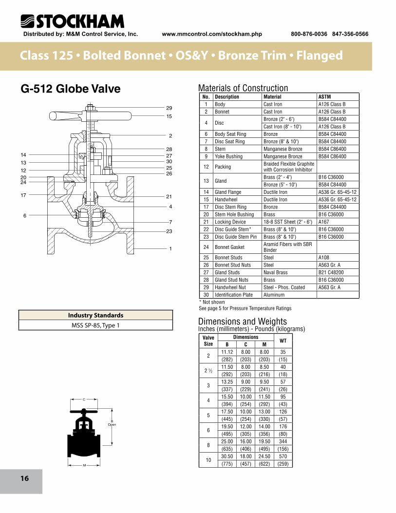
Materials of ConstructionG-512 Globe ValveNo. Description Material ASTM1 Body Cast Iron A126 Class B2 Bonnet Cast Iron A126 Class B
4 DiscBronze (2" - 6") B584 C84400Cast Iron (8" - 10") A126 Class B
6 Body Seat Ring Bronze B584 C844007 Disc Seat Ring Bronze (8" & 10") B584 C844008 Stem Manganese Bronze B584 C864009 Yoke Bushing Manganese Bronze B584 C86400
12 Packing Braided Flexible Graphite with Corrosion Inhibitor
13 GlandBrass (2" - 4") B16 C36000Bronze (5" - 10") B584 C84400
14 Gland Flange Ductile Iron A536 Gr. 65-45-1215 Handwheel Ductile Iron A536 Gr. 65-45-1217 Disc Stem Ring Bronze B584 C8440020 Stem Hole Bushing Brass B16 C3600021 Locking Device 18-8 SST Sheet (2" - 6") A16722 Disc Guide Stem* Brass (8" & 10") B16 C3600023 Disc Guide Stem Pin Brass (8" & 10") B16 C36000
24 Bonnet Gasket Aramid Fibers with SBR Binder
25 Bonnet Studs Steel A10826 Bonnet Stud Nuts Steel A563 Gr. A27 Gland Studs Naval Brass B21 C4820028 Gland Stud Nuts Brass B16 C3600029 Handwheel Nut Steel - Phos. Coated A563 Gr. A30 Identification Plate Aluminum
ValveSize
DimensionsWT
B C M
211.12 8.00 8.00 35(282) (203) (203) (15)
2 1⁄211.50 8.00 8.50 40(292) (203) (216) (18)
313.25 9.00 9.50 57(337) (229) (241) (26)
415.50 10.00 11.50 95(394) (254) (292) (43)
517.50 10.00 13.00 126(445) (254) (330) (57)
619.50 12.00 14.00 176(495) (305) (356) (80)
825.00 16.00 19.50 344(635) (406) (495) (156)
1030.50 18.00 24.50 570(775) (457) (622) (259)
Class 125 • Bolted Bonnet • OS&Y • Bronze Trim • Flanged
* Not shownSee page 5 for Pressure Temperature Ratings
Industry Standards
MSS SP-85, Type 1
Distributed by: M&M Control Service, Inc. www.mmcontrol.com/stockham.php 800-876-0036 847-356-0566
17
Materials of Construction
Dimensions and WeightsInches (millimeters) - Pounds (kilograms)
8
28
30
9
14
2
1
29
272526
4
12
20
13
17
15
6
21
24
AA OpenBB Closed
A
A
H
K
P
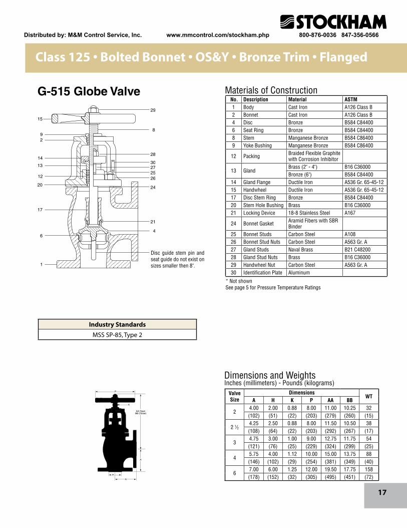
No. Description Material ASTM1 Body Cast Iron A126 Class B2 Bonnet Cast Iron A126 Class B4 Disc Bronze B584 C844006 Seat Ring Bronze B584 C844008 Stem Manganese Bronze B584 C864009 Yoke Bushing Manganese Bronze B584 C86400
12 Packing Braided Flexible Graphite with Corrosion Inhibitor
13 GlandBrass (2" - 4") B16 C36000Bronze (6") B584 C84400
14 Gland Flange Ductile Iron A536 Gr. 65-45-1215 Handwheel Ductile Iron A536 Gr. 65-45-1217 Disc Stem Ring Bronze B584 C8440020 Stem Hole Bushing Brass B16 C3600021 Locking Device 18-8 Stainless Steel A167
24 Bonnet Gasket Aramid Fibers with SBR Binder
25 Bonnet Studs Carbon Steel A10826 Bonnet Stud Nuts Carbon Steel A563 Gr. A27 Gland Studs Naval Brass B21 C4820028 Gland Stud Nuts Brass B16 C3600029 Handwheel Nut Carbon Steel A563 Gr. A30 Identification Plate Aluminum
ValveSize
DimensionsWT
A H K P AA BB
24.00 2.00 0.88 8.00 11.00 10.25 32(102) (51) (22) (203) (279) (260) (15)
2 1⁄24.25 2.50 0.88 8.00 11.50 10.50 38(108) (64) (22) (203) (292) (267) (17)
34.75 3.00 1.00 9.00 12.75 11.75 54(121) (76) (25) (229) (324) (299) (25)
45.75 4.00 1.12 10.00 15.00 13.75 88(146) (102) (29) (254) (381) (349) (40)
67.00 6.00 1.25 12.00 19.50 17.75 158(178) (152) (32) (305) (495) (451) (72)
Class 125 • Bolted Bonnet • OS&Y • Bronze Trim • Flanged
G-515 Globe Valve
* Not shownSee page 5 for Pressure Temperature Ratings
Industry Standards
MSS SP-85, Type 2
Disc guide stem pin and seat guide do not exist on sizes smaller then 8".
Distributed by: M&M Control Service, Inc. www.mmcontrol.com/stockham.php 800-876-0036 847-356-0566
18
M
C
BOpen
Materials of Construction
Dimensions and WeightsInches (millimeters) - Pounds (kilograms)
2915
9
2
28
3027
2526
12
13
148
24
17
2147
23
622
1
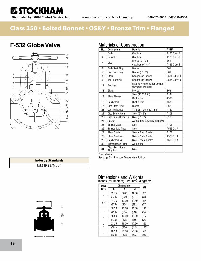
No. Description Material ASTM1 Body Cast Iron A126 Class B2 Bonnet Cast Iron A126 Class B
4 DiscBronze (2" - 3") B61Cast Iron (4" - 8") A126 Class B
6 Body Seat Ring Bronze B617 Disc Seat Ring Bronze (6" - 8") B618 Stem Manganese Bronze B584 C864009 Yoke Bushing Manganese Bronze B584 C86400
12 PackingBraided Flexible Graphite with Corrosion Inhibitor
13 Gland Bronze B62
14 Gland FlangeSteel (2", 3" & 6") A181Ductile Iron A536
15 Handwheel Ductile Iron A53617 Disc Stem Ring Bronze B6221 Locking Device 18-8 SST Sheet (2" - 5") A16722 Disc Guide Stem Steel (6" - 8") A10823 Disc Guide Stem Pin Steel (6" - 8") B10824 Gasket Aramid Fibers with SBR Binder25 Bonnet Studs Steel A10826 Bonnet Stud Nuts Steel A563 Gr. A27 Gland Studs Steel - Phos. Coated A10828 Gland Stud Nuts Steel - Phos. Coated A563 Gr. A29 Handwheel Nut Steel - Phos. Coated A563 Gr. A30 Identification Plate Aluminum
31 Disc - Disc Stem Ring Pin* Steel
ValveSize
DimensionsWT
B C M
213.75 9.00 10.50 62(349) (229) (267) (28)
2 1⁄214.75 10.00 11.50 82(375) (254) (292) (37)
316.50 10.00 12.50 118(419) (254) (318) (54)
418.50 12.00 14.00 167(470) (305) (356) (76)
623.25 16.00 17.50 320(591) (406) (445) (145)
828.50 20.00 21.00 570(724) (508) (533) (259)
Class 250 • Bolted Bonnet • OS&Y • Bronze Trim • Flanged
F-532 Globe Valve
* Not shownSee page 5 for Pressure Temperature Ratings
Industry Standards
MSS SP-85, Type 1
Distributed by: M&M Control Service, Inc. www.mmcontrol.com/stockham.php 800-876-0036 847-356-0566
19
Dimensions and WeightsInches (millimeters) - Pounds (kilograms)
Materials of Construction
See pages 21-24 for sizing and other Technical Data
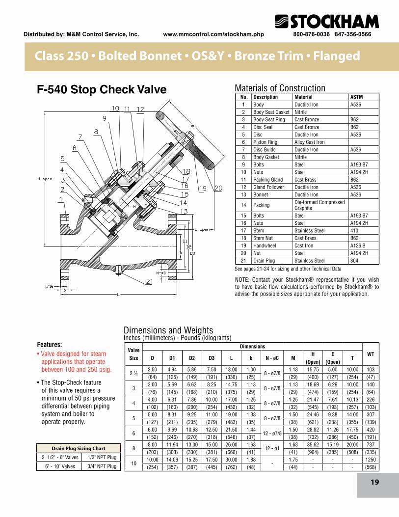
No. Description Material ASTM1 Body Ductile Iron A5362 Body Seat Gasket Nitrile3 Body Seat Ring Cast Bronze B624 Disc Seal Cast Bronze B625 Disc Ductile Iron A5366 Piston Ring Alloy Cast Iron7 Disc Guide Ductile Iron A5368 Body Gasket Nitrile9 Bolts Steel A193 B710 Nuts Steel A194 2H11 Packing Gland Cast Brass B6212 Gland Follower Ductile Iron A53613 Bonnet Ductile Iron A536
14 Packing Die-formed Compressed Graphite
15 Bolts Steel A193 B716 Nuts Steel A194 2H17 Stem Stainless Steel 41018 Stem Nut Cast Brass B6219 Handwheel Cast Iron A126 B20 Nut Steel A194 2H21 Drain Plug Stainless Steel 304
ValveSize
DimensionsWT
D D1 D2 D3 L b N - øC MH
(Open)E
(Open)T
2 1⁄22.50 4.94 5.86 7.50 13.00 1.00
8 - ø7/81.13 15.75 5.00 10.00 103
(64) (125) (149) (191) (330) (25) (29) (400) (127) (254) (47)
33.00 5.69 6.63 8.25 14.75 1.13
8 - ø7/81.13 18.69 6.29 10.00 140
(76) (145) (168) (210) (375) (29) (29) (474) (159) (254) (64)
44.00 6.31 7.86 10.00 17.00 1.25
8 - ø7/81.25 21.47 7.61 10.13 226
(102) (160) (200) (254) (432) (32) (32) (545) (193) (257) (103)
55.00 8.31 9.25 11.00 19.00 1.38
8 - ø7/81.50 24.46 9.38 14.00 307
(127) (211) (235) (279) (483) (35) (38) (621) (238) (355) (139)
66.00 9.69 10.63 12.50 21.50 1.44
12 - ø7/81.50 28.82 11.26 17.75 420
(152) (246) (270) (318) (546) (37) (38) (732) (286) (450) (191)
88.00 11.94 13.00 15.00 26.00 1.63
12 - ø11.63 35.62 15.19 20.00 737
(203) (303) (330) (381) (660) (41) (41) (904) (385) (508) (335)
1010.00 14.06 15.25 17.50 30.00 1.88
-1.75 - - - 1250
(254) (357) (387) (445) (762) (48) (44) - - - (568)
Class 250 • Bolted Bonnet • OS&Y • Bronze Trim • Flanged
F-540 Stop Check Valve
NOTE: Contact your Stockham® representative if you wish to have basic flow calculations performed by Stockham® to advise the possible sizes appropriate for your application.
Features:• Valve designed for steam applications that operate between 100 and 250 psig.
• The Stop-Check feature of this valve requires a minimum of 50 psi pressure differential between piping system and boiler to operate properly.
Drain Plug Sizing Chart
2 1/2" - 6" Valves 1/2" NPT Plug
6" - 10" Valves 3/4" NPT Plug
Distributed by: M&M Control Service, Inc. www.mmcontrol.com/stockham.php 800-876-0036 847-356-0566
20
Dimensions and WeightsInches (millimeters) - Pounds (kilograms)
Materials of Construction
See pages 21 - 24 for sizing and other Technical Data
Valve Size
DimensionsWT
D D1 D2 D3 L b N - øC M H(Open)
E (Open) T
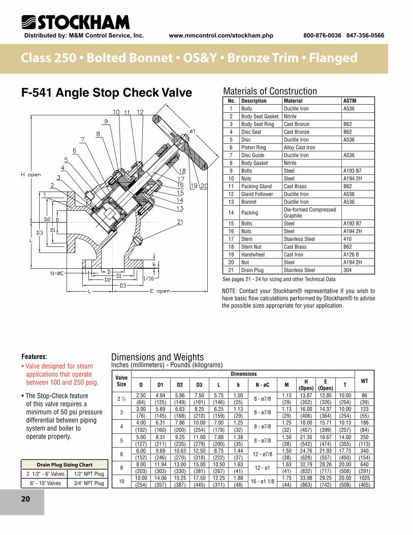
2 1⁄22.50 4.94 5.86 7.50 5.75 1.00
8 - ø7/81.13 13.87 12.85 10.00 86
(64) (125) (149) (191) (146) (25) (29) (352) (326) (254) (39)
33.00 5.69 6.63 8.25 6.25 1.13
8 - ø7/81.13 16.00 14.37 10.00 123
(76) (145) (168) (210) (159) (29) (29) (406) (364) (254) (55)
44.00 6.31 7.86 10.00 7.00 1.25
8 - ø7/81.25 18.00 15.71 10.13 186
(102) (160) (200) (254) (178) (32) (32) (457) (399) (257) (84)
55.00 8.31 9.25 11.00 7.88 1.38
8 - ø7/81.50 21.35 18.67 14.00 250
(127) (211) (235) (279) (200) (35) (38) (542) (474) (355) (113)
66.00 9.69 10.63 12.50 8.75 1.44
12 - ø7/81.50 24.76 21.93 17.75 340
(152) (246) (270) (318) (222) (37) (38) (628) (557) (450) (154)
88.00 11.94 13.00 15.00 10.50 1.63
12 - ø11.63 32.79 28.26 20.00 640
(203) (303) (330) (381) (267) (41) (41) (832) (717) (508) (291)
1010.00 14.06 15.25 17.50 12.25 1.88
16 - ø1 1/81.75 33.98 29.25 20.00 1025
(254) (357) (387) (445) (311) (48) (44) (863) (742) (508) (465)
Class 250 • Bolted Bonnet • OS&Y • Bronze Trim • Flanged
F-541 Angle Stop Check Valve
NOTE: Contact your Stockham® representative if you wish to have basic flow calculations performed by Stockham® to advise the possible sizes appropriate for your application.
No. Description Material ASTM1 Body Ductile Iron A5362 Body Seat Gasket Nitrile3 Body Seat Ring Cast Bronze B624 Disc Seal Cast Bronze B625 Disc Ductile Iron A5366 Piston Ring Alloy Cast Iron7 Disc Guide Ductile Iron A5368 Body Gasket Nitrile9 Bolts Steel A193 B710 Nuts Steel A194 2H11 Packing Gland Cast Brass B6212 Gland Follower Ductile Iron A53613 Bonnet Ductile Iron A536
14 Packing Die-formed Compressed Graphite
15 Bolts Steel A193 B716 Nuts Steel A194 2H17 Stem Stainless Steel 41018 Stem Nut Cast Brass B6219 Handwheel Cast Iron A126 B20 Nut Steel A194 2H21 Drain Plug Stainless Steel 304
Features:• Valve designed for steam applications that operate between 100 and 250 psig.
• The Stop-Check feature of this valve requires a minimum of 50 psi pressure differential between piping system and boiler to operate properly.
Drain Plug Sizing Chart
2 1/2" - 6" Valves 1/2" NPT Plug
6" - 10" Valves 3/4" NPT Plug
Distributed by: M&M Control Service, Inc. www.mmcontrol.com/stockham.php 800-876-0036 847-356-0566
21
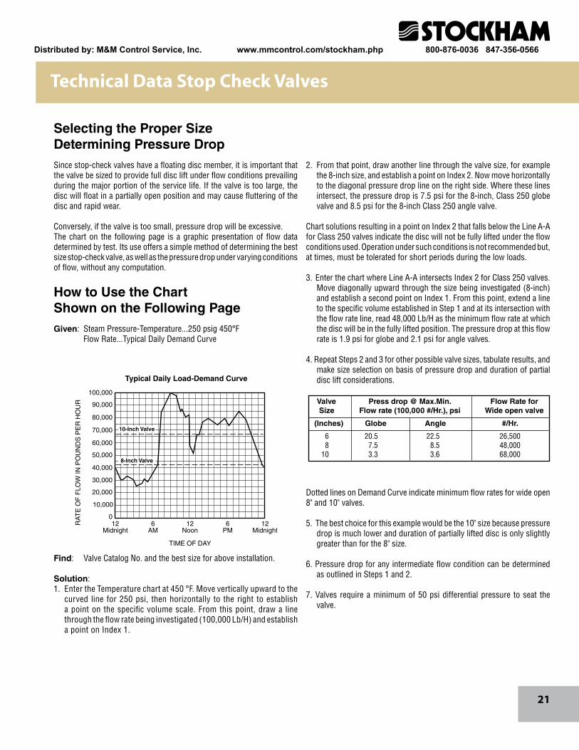
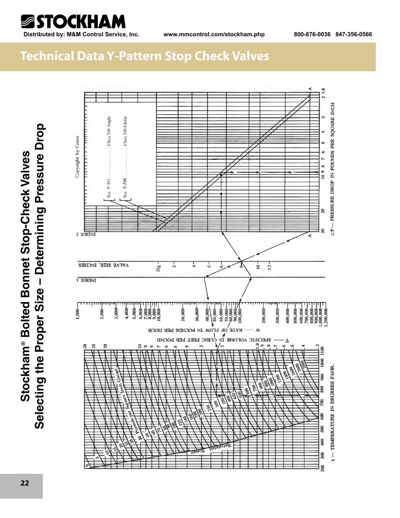
2. From that point, draw another line through the valve size, for example the 8-inch size, and establish a point on Index 2. Now move horizontally to the diagonal pressure drop line on the right side. Where these lines intersect, the pressure drop is 7.5 psi for the 8-inch, Class 250 globe valve and 8.5 psi for the 8-inch Class 250 angle valve.
Chart solutions resulting in a point on Index 2 that falls below the Line A-A for Class 250 valves indicate the disc will not be fully lifted under the flow conditions used. Operation under such conditions is not recommended but, at times, must be tolerated for short periods during the low loads.
3. Enter the chart where Line A-A intersects Index 2 for Class 250 valves. Move diagonally upward through the size being investigated (8-inch) and establish a second point on Index 1. From this point, extend a line to the specific volume established in Step 1 and at its intersection with the flow rate line, read 48,000 Lb/H as the minimum flow rate at which the disc will be in the fully lifted position. The pressure drop at this flow rate is 1.9 psi for globe and 2.1 psi for angle valves.
4. Repeat Steps 2 and 3 for other possible valve sizes, tabulate results, and make size selection on basis of pressure drop and duration of partial disc lift considerations.
Dotted lines on Demand Curve indicate minimum flow rates for wide open 8" and 10" valves.
5. The best choice for this example would be the 10" size because pressure drop is much lower and duration of partially lifted disc is only slightly greater than for the 8" size.
6. Pressure drop for any intermediate flow condition can be determined as outlined in Steps 1 and 2.
7. Valves require a minimum of 50 psi differential pressure to seat the valve.
Selecting the Proper SizeDetermining Pressure DropSince stop-check valves have a floating disc member, it is important that the valve be sized to provide full disc lift under flow conditions prevailing during the major portion of the service life. If the valve is too large, the disc will float in a partially open position and may cause fluttering of the disc and rapid wear.
Conversely, if the valve is too small, pressure drop will be excessive.The chart on the following page is a graphic presentation of flow data determined by test. Its use offers a simple method of determining the best size stop-check valve, as well as the pressure drop under varying conditions of flow, without any computation.
How to Use the ChartShown on the Following PageGiven: Steam Pressure-Temperature...250 psig 450°F Flow Rate...Typical Daily Demand Curve
Find: Valve Catalog No. and the best size for above installation.
Solution: 1. Enter the Temperature chart at 450 °F. Move vertically upward to the
curved line for 250 psi, then horizontally to the right to establish a point on the specific volume scale. From this point, draw a line through the flow rate being investigated (100,000 Lb/H) and establish a point on Index 1.
Valve Press drop @ Max.Min. Flow Rate for Size Flow rate (100,000 #/Hr.), psi Wide open valve
(Inches) Globe Angle #/Hr.
6 20.5 22.5 26,500 8 7.5 8.5 48,000 10 3.3 3.6 68,000
12Midnight
12Midnight
6AM
12Noon
6PM
0
TIME OF DAY
Typical Daily Load-Demand Curve
RA
TE
OF
FLO
W IN
PO
UN
DS
PE
R H
OU
R
10,000
20,000
30,000
40,000
50,000
60,000
70,000
80,000
90,000
100,000
10-Inch Valve
8-Inch Valve
Technical Data Stop Check Valves
Distributed by: M&M Control Service, Inc. www.mmcontrol.com/stockham.php 800-876-0036 847-356-0566
22
Sto
ckh
am®
Bo
lted
Bo
nn
et S
top
-Ch
eck
Val
ves
Sel
ecti
ng
th
e P
rop
er S
ize
– D
eter
min
ing
Pre
ssu
re D
rop
Technical Data Y-Pattern Stop Check Valves
Distributed by: M&M Control Service, Inc. www.mmcontrol.com/stockham.php 800-876-0036 847-356-0566
23
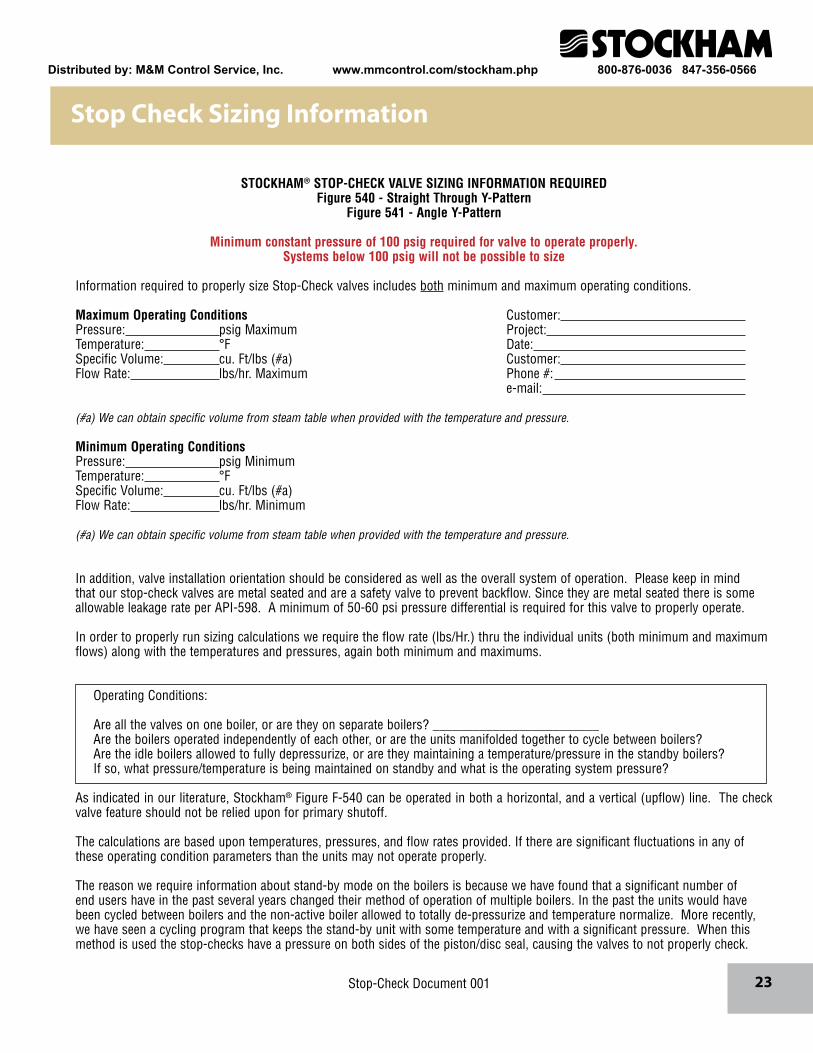
STOCKHAM® STOP-CHECK VALVE SIZING INFORMATION REQUIREDFigure 540 - Straight Through Y-Pattern
Figure 541 - Angle Y-Pattern
Minimum constant pressure of 100 psig required for valve to operate properly. Systems below 100 psig will not be possible to size
Information required to properly size Stop-Check valves includes both minimum and maximum operating conditions.
Maximum Operating Conditions Customer: Pressure: psig Maximum Project: Temperature: °F Date: Specific Volume: cu. Ft/lbs (#a) Customer: Flow Rate: lbs/hr. Maximum Phone #: e-mail:
(#a) We can obtain specific volume from steam table when provided with the temperature and pressure.
Minimum Operating ConditionsPressure: psig MinimumTemperature: °FSpecific Volume: cu. Ft/lbs (#a)Flow Rate: lbs/hr. Minimum
(#a) We can obtain specific volume from steam table when provided with the temperature and pressure.
In addition, valve installation orientation should be considered as well as the overall system of operation. Please keep in mind that our stop-check valves are metal seated and are a safety valve to prevent backflow. Since they are metal seated there is some allowable leakage rate per API-598. A minimum of 50-60 psi pressure differential is required for this valve to properly operate.
In order to properly run sizing calculations we require the flow rate (lbs/Hr.) thru the individual units (both minimum and maximum flows) along with the temperatures and pressures, again both minimum and maximums.
Operating Conditions:
Are all the valves on one boiler, or are they on separate boilers? _________________________Are the boilers operated independently of each other, or are the units manifolded together to cycle between boilers?Are the idle boilers allowed to fully depressurize, or are they maintaining a temperature/pressure in the standby boilers?If so, what pressure/temperature is being maintained on standby and what is the operating system pressure?
As indicated in our literature, Stockham® Figure F-540 can be operated in both a horizontal, and a vertical (upflow) line. The check valve feature should not be relied upon for primary shutoff.
The calculations are based upon temperatures, pressures, and flow rates provided. If there are significant fluctuations in any of these operating condition parameters than the units may not operate properly.
The reason we require information about stand-by mode on the boilers is because we have found that a significant number of end users have in the past several years changed their method of operation of multiple boilers. In the past the units would have been cycled between boilers and the non-active boiler allowed to totally de-pressurize and temperature normalize. More recently, we have seen a cycling program that keeps the stand-by unit with some temperature and with a significant pressure. When this method is used the stop-checks have a pressure on both sides of the piston/disc seal, causing the valves to not properly check.
Stop Check Sizing Information
Stop-Check Document 001
Distributed by: M&M Control Service, Inc. www.mmcontrol.com/stockham.php 800-876-0036 847-356-0566

24
As shown in these diagrams, Stockham® Y-Pattern stop-check valves used in a boiler installation can be positioned for horizontal or upward flow. The proper method for draining both Y-pattern stop-check valves and isolation gate valves is shown for typical mounting positions. Tapped and plugged drain holes are furnished. For top efficiency, be sure the proper size valve is used.
BOILER
BOILER
BOILER
BOILER
DRAIN
DRAIN
DRAIN
DRAIN
DRAIN
DRAIN
HEADER
HEADER
HEADER
HEADER
Straight-WayY-Pattern
Installed in ahorizontal line
Straight-WayY-Pattern
Installed in a vertical linefor upward flow
Angle Y-PatternInstalled for upward-
to-horizontal flow
Angle Y-PatternInstalled for
horizontal-to-downward flow
Installation Recommendations
Distributed by: M&M Control Service, Inc. www.mmcontrol.com/stockham.php 800-876-0036 847-356-0566
25
Materials of Construction
Dimensions and WeightsInches (millimeters) - Pounds (kilograms)
33
25
19
23
8
2
6
4
1
3234
B
A
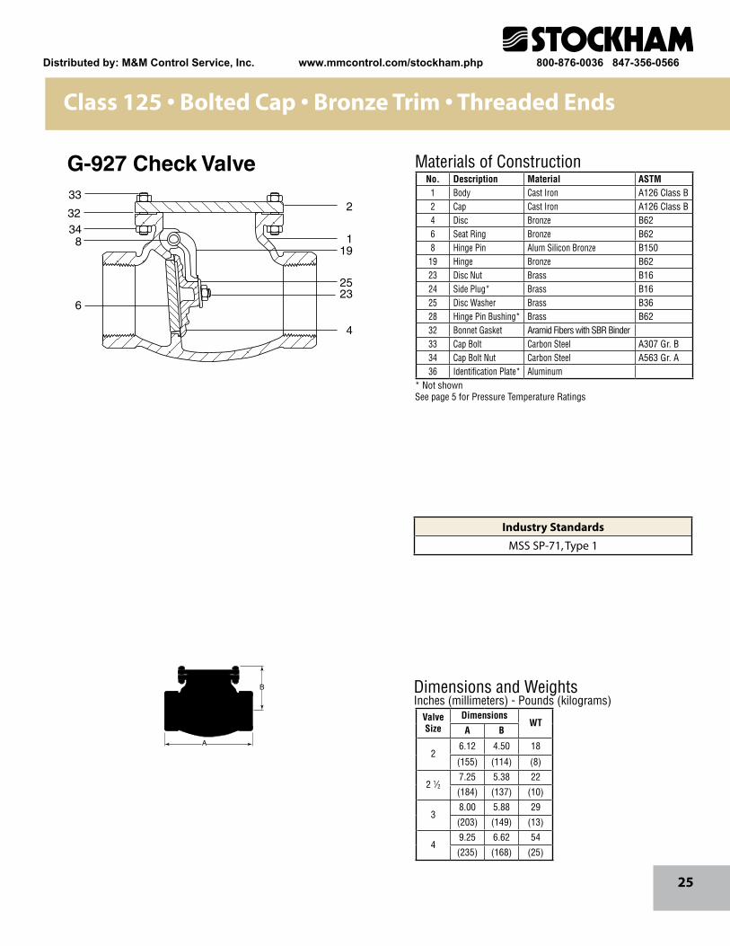
No. Description Material ASTM1 Body Cast Iron A126 Class B2 Cap Cast Iron A126 Class B4 Disc Bronze B626 Seat Ring Bronze B628 Hinge Pin Alum Silicon Bronze B150
19 Hinge Bronze B6223 Disc Nut Brass B1624 Side Plug* Brass B1625 Disc Washer Brass B3628 Hinge Pin Bushing* Brass B6232 Bonnet Gasket Aramid Fibers with SBR Binder33 Cap Bolt Carbon Steel A307 Gr. B34 Cap Bolt Nut Carbon Steel A563 Gr. A36 Identification Plate* Aluminum
ValveSize
DimensionsWT
A B
26.12 4.50 18
(155) (114) (8)
2 1⁄27.25 5.38 22
(184) (137) (10)
38.00 5.88 29
(203) (149) (13)
49.25 6.62 54
(235) (168) (25)
Class 125 • Bolted Cap • Bronze Trim • Threaded Ends
G-927 Check Valve
* Not shownSee page 5 for Pressure Temperature Ratings
Industry Standards
MSS SP-71, Type 1
Distributed by: M&M Control Service, Inc. www.mmcontrol.com/stockham.php 800-876-0036 847-356-0566
26
233
134
8
6
33
19
25
23
4
36
Materials of Construction
Dimensions and WeightsInches (millimeters) - Pounds (kilograms)
M
B
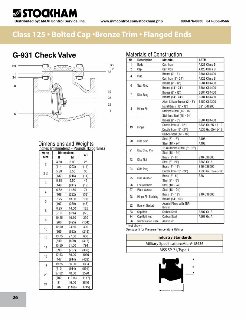
No. Description Material ASTM1 Body Cast Iron A126 Class B2 Cap Cast Iron A126 Class B
4 DiscBronze (2" - 6") B584 C84400Cast Iron (8" - 24") A126 Class B
6 Seat RingBronze (2" - 12") B584 C84400Bronze (14" - 24") B584 C84400
7 Disc RingBronze (8" - 12") B584 C84400Bronze (14" - 24") B584 C84400
8 Hinge Pin
Alum Silicon Bronze (2" - 8") B150 C64200Naval Brass (10" - 12") B21 C48200Stainless Steel (14" - 16") Stainless Steel (18" - 24")
19 Hinge
Bronze (2" - 6") B584 C84400Ductile Iron (8" - 12") A536 Gr. 65-45-12Ductile Iron (18" - 24") A536 Gr. 65-45-12Carbon Steel (14" - 16")
20 Disc StudSteel (8" - 16") A108Steel (18" - 24") A108
21 Disc Stud Pin18-8 Stainless Steel (8" - 16") Steel (18" - 24")
23 Disc NutBrass (2" - 6") B16 C36000Steel (8" - 24") A563 Gr. A
24 Side Plug Brass (2" - 16") B16 C36000Ductile Iron (18" - 24") A536 Gr. 65-45-12
25 Disc WasherBrass (2" - 6") B36Steel (8" - 16")
26 Lockwasher* Steel (18" - 24") 27 Plain Washer* Steel (18" - 24")
28 Hinge Pin Bushing*Brass (2" - 12") B16 C36000Bronze (14" - 16")
32 Bonnet Gasket Aramid Fibers with SBR Binder
33 Cap Bolt Carbon Steel A307 Gr. B34 Cap Bolt Nut Carbon Steel A563 Gr. A36 Identification Plate Aluminum
ValveSize
DimensionsWT
B M
24.50 8.00 25(114) (203) (11)
2 1⁄25.38 8.50 30(137) (216) (14)
35.88 9.50 42(149) (241) (19)
46.62 11.50 74(168) (292) (33)
57.75 13.00 100(197) (330) (45)
68.25 14.00 125(210) (356) (56)
810.25 19.50 230(260) (495) (104)
1012.00 24.50 490(305) (622) (219)
12 13.75 27.50 660(349) (699) (317)
14 15.50 31.00 794(393) (787) (360)
16 17.63 36.00 1020(447) (914) (462)
18 19.25 36.00 1304(610) (914) (591)
20 27.62 40.00 2590(702) (1016) (1117)
24 31 46.00 3840(787) (1168) (1745)
Class 125 • Bolted Cap •Bronze Trim • Flanged Ends
G-931 Check Valve
* Not shownSee page 5 for Pressure Temperature Ratings
Industry Standards
Military Specification: MIL-V-18436
MSS SP-71, Type 1
Distributed by: M&M Control Service, Inc. www.mmcontrol.com/stockham.php 800-876-0036 847-356-0566
27
M
B
Materials of Construction
* Not shown† Parts indicated are necessary for changing regular valve to outside lever and weight. See page 6 for Lever and Weight Technical Orientation Data
See page 5 for Pressure-Temperature Ratings
32
332
26
15
19
25
4
23
34
1
6
Dimensions and WeightsInches (millimeters) - Pounds (kilograms)
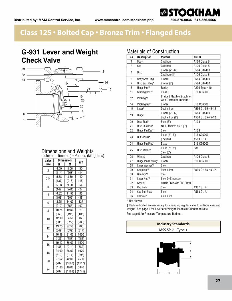
No. Description Material ASTM1 Body Cast Iron A126 Class B2 Cap Cast Iron A126 Class B
4 DiscBronze (2" - 6") B584 C84400Cast Iron (8") A126 Class B
6 Body Seat Ring Bronze B584 C844007 Disc Seat Ring* Bronze (8") B584 C844008 Hinge Pin*† Exelloy A276 Type 410
11 Stuffing Box*† Brass B16 C36000
12 Packing*† Braided Flexible Graphite with Corrosion Inhibitor
14 Packing Nut*† Bronze B16 C3600015 Lever† Ductile Iron A536 Gr. 65-45-12
19 Hinge†Bronze (2" - 6") B584 C84400Ductile Iron (8") A536 Gr. 65-45-12
20 Disc Stud* Steel (8") A10821 Disc Stud Pin* 18-8 Stainless Steel (8")22 Hinge Pin Key*† Steel A108
23 Nut for DiscBrass (2" - 6") B16 C36000(8") Steel A563 Gr. A
24 Hinge Pin Plug* Brass B16 C36000
25 Disc WasherBrass (2" - 6") B36Steel (8")
26 Weight† Cast Iron A126 Class B27 Hinge Pin Bushing* Bronze B16 C3600028 Lever Washer*† Steel29 Coupling*† Ductile Iron A536 Gr. 65-45-1230 Gib-Key*† Steel31 Lever Nut*† Steel Di-Chromate32 Gasket† Aramid Fibers with SBR Binder33 Cap Bolts Steel A307 Gr. B34 Cap Bolt Nuts Steel A563 Gr. A36 ID Plate* Aluminum
ValveSize
DimensionsWT
B M
24.50 8.00 30(114) (203) (14)
2 1⁄25.38 8.50 40(137) (216) (18)
35.88 9.50 54(149) (241) (24)
4 6.62 11.50 85(168) (292) (38)
6 8.25 14.00 137(210) (356) (62)
8 10.25 19.50 240(260) (495) (108)
10 12.00 24.50 460(305) (622) (208)
1213.75 27.50 700(349) (699) (317)
1416.88 31.00 1060(429) (787) (481)
1619.12 36.00 1500(486) (914) (682)
1824.00 36.00 1970(610) (914) (895)
2027.62 42.00 2590(702) (1067) (1117)
2431.00 46.00 3840(787) (1168) (1745)
Class 125 • Bolted Cap • Bronze Trim • Flanged Ends
G-931 Lever and WeightCheck Valve
Industry Standards
MSS SP-71, Type 1
Distributed by: M&M Control Service, Inc. www.mmcontrol.com/stockham.php 800-876-0036 847-356-0566
28
33
34
36
32
19
25
23
4
1
8
2
Dimensions and WeightsInches (millimeters) - Pounds (kilograms)
Materials of Construction
M
B
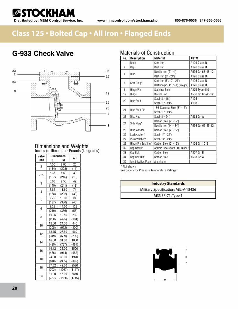
No. Description Material ASTM1 Body Cast Iron A126 Class B2 Cap Cast Iron A126 Class B
4 DiscDuctile Iron (2" - 4") A536 Gr. 65-45-12Cast Iron (6" - 24") A126 Class B
6 Seat Ring*Cast Iron (5", 10" - 24") A126 Class BCast Iron (2" - 4", 6" - 8") (Integral) A126 Class B
8 Hinge Pin Stainless Steel A276 Type 41019 Hinge Ductile Iron A536 Gr. 65-45-12
20 Disc StudSteel (8" - 16") A108Steel (18" - 24") A108
21 Disc Stud Pin18-8 Stainless Steel (8" - 16") Steel (18" - 24")
23 Disc Nut Steel (8" - 24") A563 Gr. A
24 Side Plug* Carbon Steel (2" - 12") Ductile Iron (14" - 24") A536 Gr. 65-45-12
25 Disc Washer Carbon Steel (2" - 12") 26 Lockwasher* Steel (14" - 24") 27 Plain Washer* Steel (14" - 24") 28 Hinge Pin Bushing* Carbon Steel (2" - 12") A108 Gr. 101832 Cap Gasket Aramid Fibers with SBR Binder33 Cap Bolt Carbon Steel A307 Gr. B34 Cap Bolt Nut Carbon Steel A563 Gr. A36 Identification Plate Aluminum
ValveSize
DimensionsWT
B M
24.50 8.00 25(114) (203) (11)
2 1⁄25.38 8.50 30(137) (216) (13)
35.88 9.50 42(149) (241) (19)
46.62 11.50 74(168) (292) (33)
57.75 13.00 100(197) (330) (45)
68.25 14.00 125(210) (356) (56)
810.25 19.50 230(260) (495) (104)
1012.00 24.50 440(305) (622) (200)
1213.75 27.50 660(349) (699) (299)
1416.88 31.00 1060(429) (787) (481)
1619.12 36.00 1500(486) (914) (682)
1824.00 38.00 1970(610) (965) (895)
2027.62 42.00 2590(702) (1067) (1117)
2431.00 46.00 3840(787) (1168) (1745)
Class 125 • Bolted Cap • All Iron • Flanged Ends
G-933 Check Valve
* Not shownSee page 5 for Pressure Temperature Ratings
Industry Standards
Military Specification: MIL-V-18436
MSS SP-71, Type 1
Distributed by: M&M Control Service, Inc. www.mmcontrol.com/stockham.php 800-876-0036 847-356-0566
29
Materials of Construction
Dimensions and WeightsInches (millimeters) - Pounds (kilograms)
1314
16
45
8
9
37
152
1
12
10
M
B
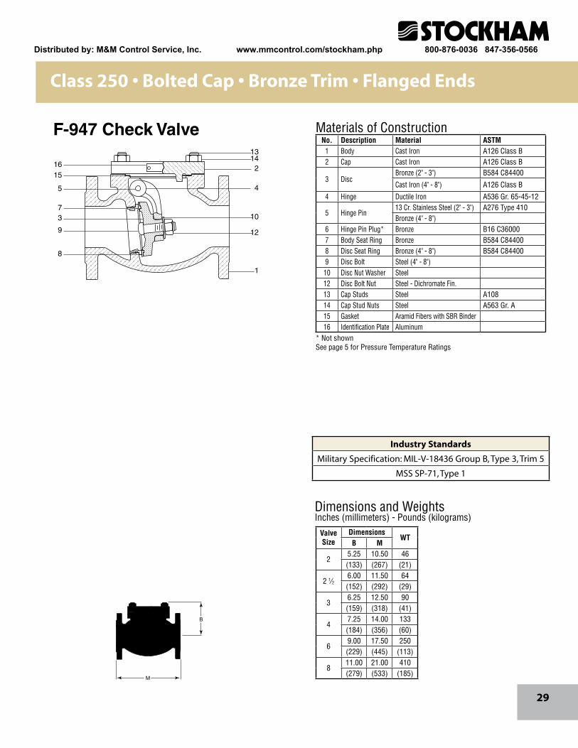
No. Description Material ASTM1 Body Cast Iron A126 Class B2 Cap Cast Iron A126 Class B
3 DiscBronze (2" - 3") B584 C84400
Cast Iron (4" - 8") A126 Class B
4 Hinge Ductile Iron A536 Gr. 65-45-12
5 Hinge Pin 13 Cr. Stainless Steel (2" - 3") A276 Type 410Bronze (4" - 8")
6 Hinge Pin Plug* Bronze B16 C360007 Body Seat Ring Bronze B584 C844008 Disc Seat Ring Bronze (4" - 8") B584 C844009 Disc Bolt Steel (4" - 8")
10 Disc Nut Washer Steel12 Disc Bolt Nut Steel - Dichromate Fin.13 Cap Studs Steel A10814 Cap Stud Nuts Steel A563 Gr. A15 Gasket Aramid Fibers with SBR Binder16 Identification Plate Aluminum
ValveSize
DimensionsWT
B M
25.25 10.50 46(133) (267) (21)
2 1⁄26.00 11.50 64(152) (292) (29)
36.25 12.50 90(159) (318) (41)
47.25 14.00 133(184) (356) (60)
69.00 17.50 250(229) (445) (113)
811.00 21.00 410(279) (533) (185)
Class 250 • Bolted Cap • Bronze Trim • Flanged Ends
F-947 Check Valve
* Not shownSee page 5 for Pressure Temperature Ratings
Industry Standards
Military Specification: MIL-V-18436 Group B, Type 3, Trim 5
MSS SP-71, Type 1
Distributed by: M&M Control Service, Inc. www.mmcontrol.com/stockham.php 800-876-0036 847-356-0566
30
Dimensions and WeightsInches (millimeters) - Pounds (kilograms)
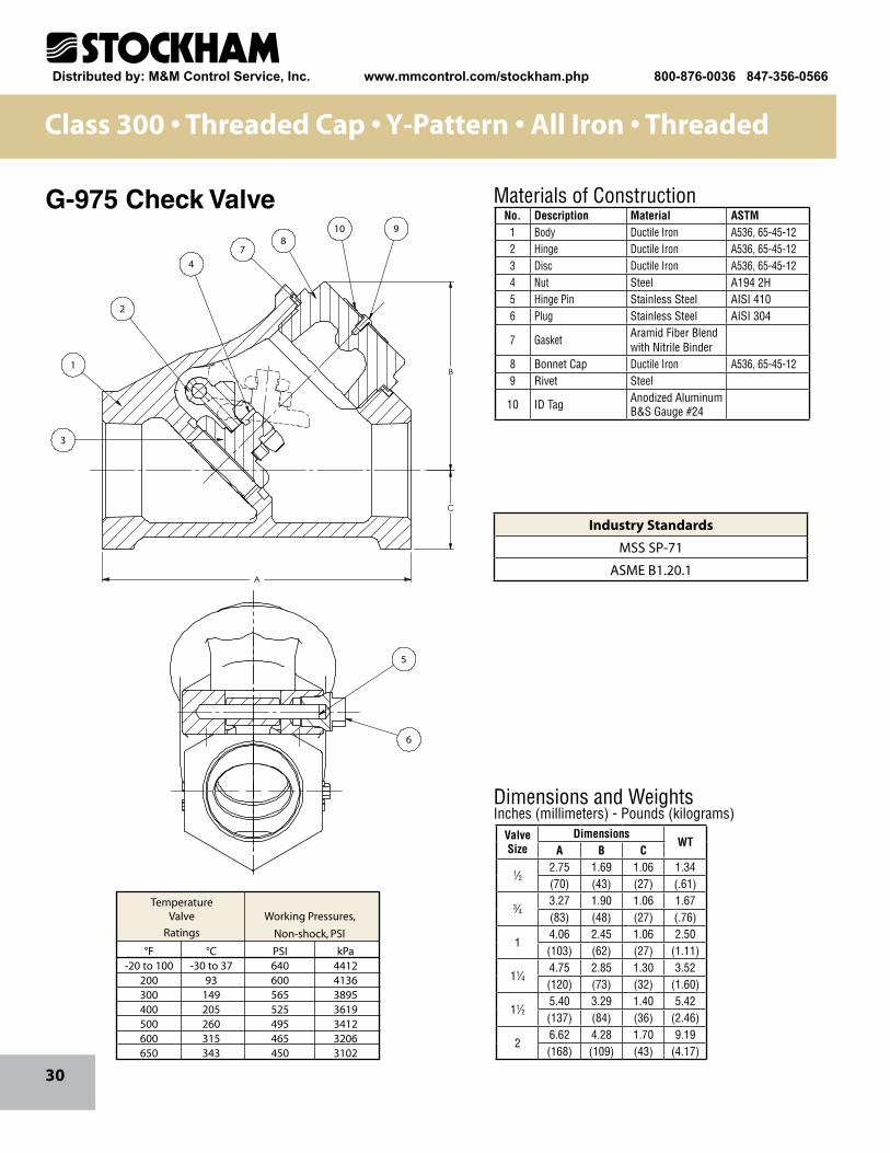
Materials of ConstructionNo. Description Material ASTM
1 Body Ductile Iron A536, 65-45-122 Hinge Ductile Iron A536, 65-45-123 Disc Ductile Iron A536, 65-45-124 Nut Steel A194 2H5 Hinge Pin Stainless Steel AISI 4106 Plug Stainless Steel AISI 304
7 GasketAramid Fiber Blend with Nitrile Binder
8 Bonnet Cap Ductile Iron A536, 65-45-129 Rivet Steel
10 ID Tag Anodized Aluminum B&S Gauge #24
ValveSize
DimensionsWT
A B C
1⁄22.75 1.69 1.06 1.34(70) (43) (27) (.61)
3⁄43.27 1.90 1.06 1.67(83) (48) (27) (.76)
14.06 2.45 1.06 2.50(103) (62) (27) (1.11)
11⁄44.75 2.85 1.30 3.52(120) (73) (32) (1.60)
11⁄25.40 3.29 1.40 5.42(137) (84) (36) (2.46)
26.62 4.28 1.70 9.19(168) (109) (43) (4.17)
Class 300 • Threaded Cap • Y-Pattern • All Iron • Threaded
G-975 Check Valve
6
5
A
B
C
8
2
4
3
1
10 9
7
6
5
A
B
C
8
2
4
3
1
10 9
7
Temperature Valve Working Pressures,
Ratings Non-shock, PSI
°F °C PSI kPa -20 to 100 -30 to 37 640 4412 200 93 600 4136 300 149 565 3895 400 205 525 3619 500 260 495 3412 600 315 465 3206 650 343 450 3102
Industry Standards
MSS SP-71
ASME B1.20.1
Distributed by: M&M Control Service, Inc. www.mmcontrol.com/stockham.php 800-876-0036 847-356-0566
31
Dimensions and WeightsInches (millimeters) - Pounds (kilograms)
Materials of Construction
3
1 5
72
6
8
4
A Dia.
C Minimum
FlangeBore
B
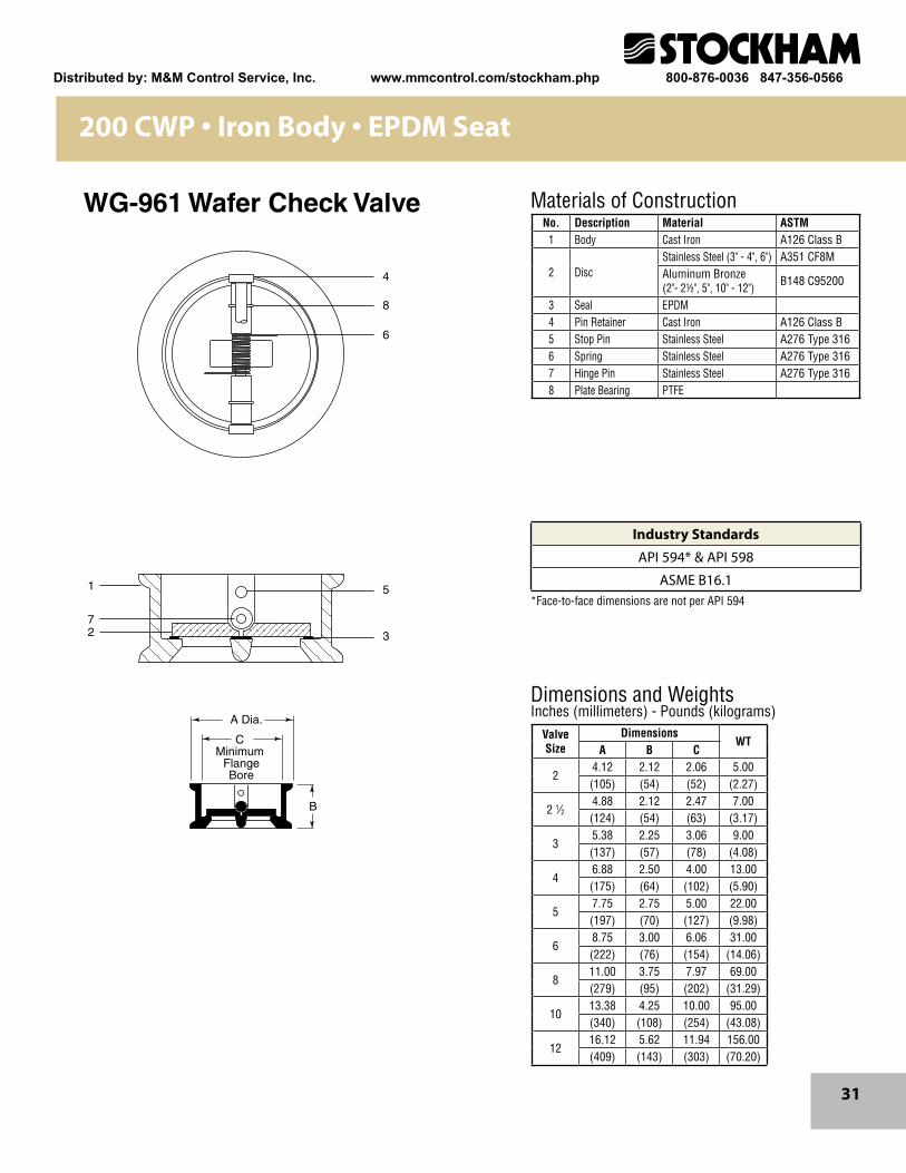
No. Description Material ASTM1 Body Cast Iron A126 Class B
2 DiscStainless Steel (3" - 4", 6") A351 CF8MAluminum Bronze (2"- 2½", 5", 10" - 12") B148 C95200
3 Seal EPDM4 Pin Retainer Cast Iron A126 Class B5 Stop Pin Stainless Steel A276 Type 3166 Spring Stainless Steel A276 Type 3167 Hinge Pin Stainless Steel A276 Type 3168 Plate Bearing PTFE
ValveSize
DimensionsWT
A B C
24.12 2.12 2.06 5.00(105) (54) (52) (2.27)
2 1⁄24.88 2.12 2.47 7.00(124) (54) (63) (3.17)
35.38 2.25 3.06 9.00(137) (57) (78) (4.08)
46.88 2.50 4.00 13.00(175) (64) (102) (5.90)
57.75 2.75 5.00 22.00(197) (70) (127) (9.98)
68.75 3.00 6.06 31.00(222) (76) (154) (14.06)
811.00 3.75 7.97 69.00(279) (95) (202) (31.29)
1013.38 4.25 10.00 95.00(340) (108) (254) (43.08)
1216.12 5.62 11.94 156.00(409) (143) (303) (70.20)
200 CWP • Iron Body • EPDM Seat
WG-961 Wafer Check Valve
*Face-to-face dimensions are not per API 594
Industry Standards
API 594* & API 598
ASME B16.1
Distributed by: M&M Control Service, Inc. www.mmcontrol.com/stockham.php 800-876-0036 847-356-0566
32
3
1
5
46
9
10
12
7
8
2
11
A Dia.
B
C Minimum
FlangeBore
Materials of Construction
Dimensions and WeightsInches (millimeters) - Pounds (kilograms)
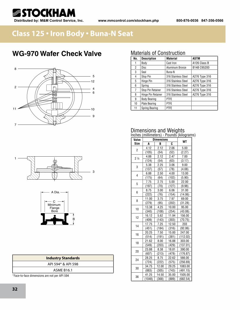
No. Description Material ASTM1 Body Cast Iron A126 Class B2 Disc Aluminum Bronze B148 C952003 Seal Buna-N4 Stop Pin 316 Stainless Steel A276 Type 3165 Hinge Pin 316 Stainless Steel A276 Type 3166 Spring 316 Stainless Steel A276 Type 3167 Stop Pin Retainer 316 Stainless Steel A276 Type 3168 Hinge Pin Retainer 316 Stainless Steel A276 Type 3169 Body Bearing PTFE10 Plate Bearing PTFE11 Spring Bearing PTFE
ValveSize
DimensionsWT
A B C
24.12 2.12 2.06 5.00(105) (54) (52) (2.27)
2 ½4.88 2.12 2.47 7.00(124) (54) (63) (3.17)
35.38 2.25 3.06 9.00(137) (57) (78) (4.08)
46.88 2.50 4.00 13.00(175) (64) (102) (5.90)
57.75 2.75 5.00 22.00(197) (70) (127) (9.98)
68.75 3.00 6.06 31.00(222) (76) (154) (14.06)
811.00 3.75 7.97 69.00(279) (95) (202) (31.28)
1013.38 4.25 10.00 95.00(340) (108) (254) (43.08)
1216.12 5.62 11.94 156.00(409) (143) (303) (70.75)
1417.75 7.25 12.50 203(451) (184) (316) (92.06)
1620.25 7.50 15.00 247.00(514) (191) (381) (112.02)
1821.62 8.00 16.88 303.00(549) (203) (429) (137.01)
2023.88 8.38 18.81 390.00(607) (213) (478) (176.87)
2428.25 8.75 22.62 566.00(724) (222) (575) (256.69)
3034.75 12.00 29.25 1083.00(883) (305) (743) (491.15)
3641.25 14.50 35.00 1505.00(1048) (368) (889) (682.54)
Class 125 • Iron Body • Buna-N Seat
WG-970 Wafer Check Valve
*Face-to-face dimensions are not per API 594
Industry Standards
API 594* & API 598
ASME B16.1
Distributed by: M&M Control Service, Inc. www.mmcontrol.com/stockham.php 800-876-0036 847-356-0566

33
21
4746
27
26
2
25
4
1
15
948
13
12
2423
8
7
6
M
C
BOpen
Dimensions and WeightsInches (millimeters) - Pounds (kilograms)
Materials of Construction No. Description Material ASTM
1 Body Cast Iron A126 Class B2 Bonnet Cast Iron A126 Class B
4 DiscBronze (2") B61 C92200Bronze (21/2" & 3") B584 C84400Cast Iron (4" - 12") A126 Class B
6 Body Seat Ring Bronze B584 C844007 Disc Seat Ring Bronze (4" - 12") B584 C844008 Stem Manganese Bronze B584 C864009 Yoke Sleeve Manganese Bronze B584 C86400
12 Packing Braided Flexible Graphite with Corrosion Inhibitor
13Gland (1 Piece) Ductile Iron (2" - 8") A536 Gr. 65-45-12Gland* Bronze (10" & 12") B584 C84400Gland Flange* Ductile Iron (10" & 12") A536 Gr. 65-45-12
15 Handwheel Ductile Iron A536 Gr. 65-45-12
21 Handwheel NutSintered Nickel Steel (2" - 8") B484 Gr. 2 CL B Type IIDuctile Iron (10" - 12") A536 Gr. 65-45-12
23 Bonnet Gasket Aramid Fibers with SBR Binder24 Bonnet Bolt Carbon Steel A307 Gr. B25 Bonnet Bolt Nut Carbon Steel A563 Gr. A
26Gland Bolt Carbon Steel A307 Gr. BGland Eyebolt Carbon Steel
27 Gland Bolt Nut Carbon Steel A563 Gr. A
46 Yoke CapDuctile Iron (2" - 8") A536Cast Iron (10" - 12") A126 Class B
47 Yoke Cap Bolt Carbon Steel A307 Gr. B48 Yoke Cap Bolt Nut Carbon Steel A563 Gr. A
ValveSize
DimensionsWT
B C M
214.75 8.00 7.00 33(375) (203) (178) (15)
2 1⁄216.06 8.00 7.50 47(408) (203) (191) (21)
317.38 8.00 8.00 58(441) (203) (203) (26)
421.44 10.00 9.00 97(545) (254) (229) (44)
525.81 10.00 10.00 135(656) (254) (254) (61)
630.31 12.00 10.50 162(770) (305) (267) (73)
837.75 14.00 11.50 280(959) (356) (292) (126)
1044.94 16.00 13.00 502(1141) (406) (330) (228)
1253.69 18.00 14.00 670(1364) (457) (356) (304)
Class 125 • Bolted Bonnet • OS&Y • Bronze Trim • Flanged
G-623-I InternationalIron Gate Valve
* Not shownSee page 5 for Pressure Temperature Ratings
Industry Standards
MSS SP-70, Type 1
Distributed by: M&M Control Service, Inc. www.mmcontrol.com/stockham.php 800-876-0036 847-356-0566
34
M
C
B
2115
13
12
2
27
26
1128
23
8
7
4
6
1
Dimensions and WeightsInches (millimeters) - Pounds (kilograms)
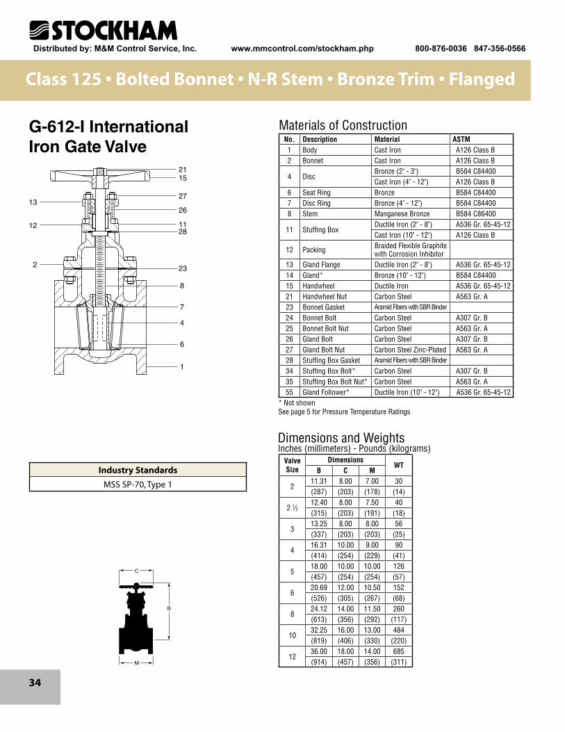
Materials of ConstructionNo. Description Material ASTM1 Body Cast Iron A126 Class B2 Bonnet Cast Iron A126 Class B
4 DiscBronze (2" - 3") B584 C84400Cast Iron (4" - 12") A126 Class B
6 Seat Ring Bronze B584 C844007 Disc Ring Bronze (4" - 12") B584 C844008 Stem Manganese Bronze B584 C86400
11 Stuffing BoxDuctile Iron (2" - 8") A536 Gr. 65-45-12Cast Iron (10" - 12") A126 Class B
12 Packing Braided Flexible Graphite with Corrosion Inhibitor
13 Gland Flange Ductile Iron (2" - 8") A536 Gr. 65-45-1214 Gland* Bronze (10" - 12") B584 C8440015 Handwheel Ductile Iron A536 Gr. 65-45-1221 Handwheel Nut Carbon Steel A563 Gr. A23 Bonnet Gasket Aramid Fibers with SBR Binder
24 Bonnet Bolt Carbon Steel A307 Gr. B25 Bonnet Bolt Nut Carbon Steel A563 Gr. A26 Gland Bolt Carbon Steel A307 Gr. B27 Gland Bolt Nut Carbon Steel Zinc-Plated A563 Gr. A28 Stuffing Box Gasket Aramid Fibers with SBR Binder
34 Stuffing Box Bolt* Carbon Steel A307 Gr. B35 Stuffing Box Bolt Nut* Carbon Steel A563 Gr. A55 Gland Follower* Ductile Iron (10" - 12") A536 Gr. 65-45-12
ValveSize
DimensionsWT
B C M
211.31 8.00 7.00 30(287) (203) (178) (14)
2 1⁄212.40 8.00 7.50 40(315) (203) (191) (18)
313.25 8.00 8.00 56(337) (203) (203) (25)
416.31 10.00 9.00 90(414) (254) (229) (41)
518.00 10.00 10.00 126(457) (254) (254) (57)
620.69 12.00 10.50 152(526) (305) (267) (68)
824.12 14.00 11.50 260(613) (356) (292) (117)
1032.25 16.00 13.00 484(819) (406) (330) (220)
1236.00 18.00 14.00 685(914) (457) (356) (311)
Class 125 • Bolted Bonnet • N-R Stem • Bronze Trim • Flanged
G-612-I InternationalIron Gate Valve
* Not shownSee page 5 for Pressure Temperature Ratings
Industry Standards
MSS SP-70, Type 1
Distributed by: M&M Control Service, Inc. www.mmcontrol.com/stockham.php 800-876-0036 847-356-0566
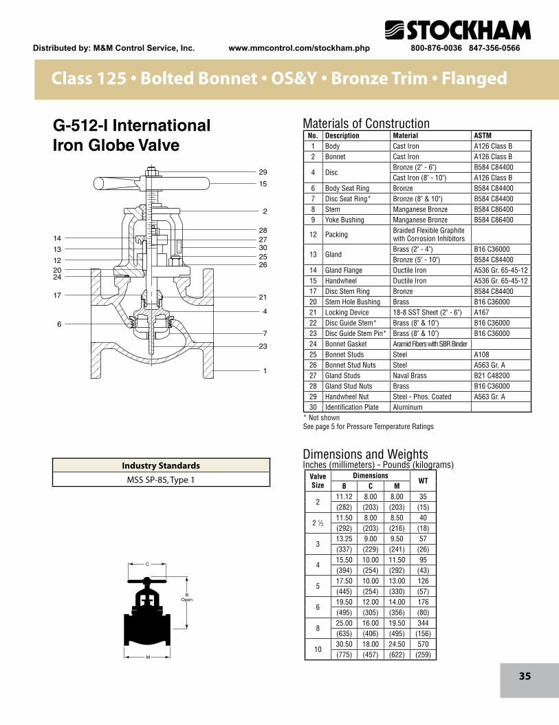
35
15
2
28
302526
21
4
23
7
1
2714
13
122024
17
6
29
Dimensions and WeightsInches (millimeters) - Pounds (kilograms)
M
C
BOpen
Materials of ConstructionNo. Description Material ASTM1 Body Cast Iron A126 Class B2 Bonnet Cast Iron A126 Class B
4 DiscBronze (2" - 6") B584 C84400Cast Iron (8" - 10") A126 Class B
6 Body Seat Ring Bronze B584 C844007 Disc Seat Ring* Bronze (8" & 10") B584 C844008 Stem Manganese Bronze B584 C864009 Yoke Bushing Manganese Bronze B584 C86400
12 Packing Braided Flexible Graphite with Corrosion Inhibitors
13 GlandBrass (2" - 4") B16 C36000Bronze (5" - 10") B584 C84400
14 Gland Flange Ductile Iron A536 Gr. 65-45-1215 Handwheel Ductile Iron A536 Gr. 65-45-1217 Disc Stem Ring Bronze B584 C8440020 Stem Hole Bushing Brass B16 C3600021 Locking Device 18-8 SST Sheet (2" - 6") A16722 Disc Guide Stem* Brass (8" & 10") B16 C3600023 Disc Guide Stem Pin* Brass (8" & 10") B16 C3600024 Bonnet Gasket Aramid Fibers with SBR Binder25 Bonnet Studs Steel A10826 Bonnet Stud Nuts Steel A563 Gr. A27 Gland Studs Naval Brass B21 C4820028 Gland Stud Nuts Brass B16 C3600029 Handwheel Nut Steel - Phos. Coated A563 Gr. A30 Identification Plate Aluminum
ValveSize
DimensionsWT
B C M
211.12 8.00 8.00 35(282) (203) (203) (15)
2 1⁄211.50 8.00 8.50 40(292) (203) (216) (18)
313.25 9.00 9.50 57(337) (229) (241) (26)
415.50 10.00 11.50 95(394) (254) (292) (43)
517.50 10.00 13.00 126(445) (254) (330) (57)
619.50 12.00 14.00 176(495) (305) (356) (80)
825.00 16.00 19.50 344(635) (406) (495) (156)
1030.50 18.00 24.50 570(775) (457) (622) (259)
Class 125 • Bolted Bonnet • OS&Y • Bronze Trim • Flanged
G-512-I InternationalIron Globe Valve
* Not shownSee page 5 for Pressure Temperature Ratings
Industry Standards
MSS SP-85, Type 1
Distributed by: M&M Control Service, Inc. www.mmcontrol.com/stockham.php 800-876-0036 847-356-0566
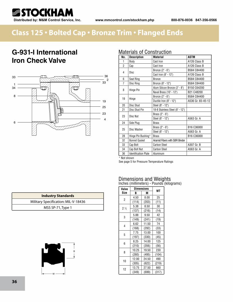
36
233
134
8
6
33
19
25
23
4
36
Materials of Construction
Dimensions and WeightsInches (millimeters) - Pounds (kilograms)
M
B
No. Description Material ASTM1 Body Cast Iron A126 Class B2 Cap Cast Iron A126 Class B
4 DiscBronze (2" - 6") B584 C84400Cast Iron (8" - 12") A126 Class B
6 Seat Ring Bronze B584 C844007 Disc Ring Bronze (8" - 12") B584 C84400
8 Hinge PinAlum Silicon Bronze (2" - 8") B150 C64200Naval Brass (10" - 12") B21 C48200
19 HingeBronze (2" - 6") B584 C84400Ductile Iron (8" - 12") A536 Gr. 65-45-12
20 Disc Stud Steel (8" - 12") 21 Disc Stud Pin 18-8 Stainless Steel (8" - 12")
23 Disc NutBrass (2" - 6") Steel (8" - 12") A563 Gr. A
24 Side Plug Brass
25 Disc WasherBrass (2" - 6") B16 C36000Steel (8" - 12") A563 Gr. A
28 Hinge Pin Bushing* Brass B16 C3600032 Bonnet Gasket Aramid Fibers with SBR Binder33 Cap Bolt Carbon Steel A307 Gr. B34 Cap Bolt Nut Carbon Steel A563 Gr. A36 Identification Plate Aluminum
ValveSize
DimensionsWT
B M
24.50 8.00 25(114) (203) (11)
2 1⁄25.38 8.50 30(137) (216) (14)
35.88 9.50 42(149) (241) (19)
46.62 11.50 74(168) (292) (33)
57.75 13.00 100(197) (330) (45)
68.25 14.00 125(210) (356) (56)
810.25 19.50 230(260) (495) (104)
1012.00 24.50 490(305) (622) (219)
12 13.75 27.50 660(349) (699) (317)
Class 125 • Bolted Cap • Bronze Trim • Flanged Ends
G-931-I InternationalIron Check Valve
* Not shownSee page 5 for Pressure Temperature Ratings
Industry Standards
Military Specification: MIL-V-18436
MSS SP-71, Type 1
Distributed by: M&M Control Service, Inc. www.mmcontrol.com/stockham.php 800-876-0036 847-356-0566

37
Notes
Distributed by: M&M Control Service, Inc. www.mmcontrol.com/stockham.php 800-876-0036 847-356-0566
38
Notes
Distributed by: M&M Control Service, Inc. www.mmcontrol.com/stockham.php 800-876-0036 847-356-0566
39
Notes
Distributed by: M&M Control Service, Inc. www.mmcontrol.com/stockham.php 800-876-0036 847-356-0566

®
CRANE ChemPharma & Energy
Crane Co., and its subsidiaries cannot accept responsibility for possible errors in catalogues, brochures, other printed materials, and websiteinformation. Crane Co. reserves the right to alter its products without notice, including products already on order provided that such alte-ration can be made without changes being necessary in specifications already agreed. All trademarks in this material are property of the Crane Co. or its subsidiaries. The Crane and Crane brands logotype, in alphabetical order, (ALOYCO®, CENTER LINE®, COMPAC-NOZ®, CRANE®, DEPA® & ELRO®, DUO-CHEK®, FLOWSEAL®, JENKINS®, KROMBACH®, NOZ-CHEK®, PACIFIC®, RESISTOFLEX®, REVO®, SAUNDERS®, STOCKHAM®, TRIANGLE®, UNI-CHEK®, VALVES®, WTA®, and XOMOX®) are registered trademarks of Crane Co. All rights reserved.
®
www.flowoffluids.com
brands you trust.
Distributed by: M&M Control Service, Inc. www.mmcontrol.com/stockham.php 800-876-0036 847-356-0566