bow & bay windows - loewen · bow & bay windows f3 product features ... f19 bow & bay...
TRANSCRIPT

BOW & BAY WINDOWS
F3 Product FeaturesF4 SpecificationsF5 F9 Framed Wall Product Elevations
F5 34˚ Kitchen Bay & 34˚ Bay Window Casement CombinationsF6 34˚ Kitchen Bay & 34˚ Bay Window Casement/Picture
CombinationsF7 45˚ Kitchen Bay & 45˚ Bay Window Casement CombinationsF8 45˚ Kitchen Bay & 45˚ Bay Window Casement/Picture
CombinationsF9 10˚ Bow Window Combinations
F10 F13 Framed Wall Product Details
F10 Bow & Bay Window Construction DetailsF11 Bow WindowF12 34˚ Bay WindowF13 45˚ Bay Window
F14 F18 Straight Wall Product Elevations
F14 34˚ Kitchen Bay & 34˚ Bay Window Casement CombinationsF15 34˚ Kitchen Bay & 34˚ Bay Window Casement/Picture
CombinationsF16 45˚ Kitchen Bay & 45˚ Bay Window Casement CombinationsF17 45˚ Kitchen Bay & 45˚ Bay Window Casement/Picture
CombinationsF18 10˚ Bow Window Combinations
F19 F22 Straight Wall Product Details
F19 Bow & Bay Window Construction DetailsF20 Bow WindowF21 Bay WindowF22 45˚ Bay Window
F23 F26 90˚ Corner Product Details
F23 Picture/Direct Set Bay WindowF24 Casement Bay WindowF25 Picture/Direct Set Bay Window (Butt Glazed)F26 Casement Bay Window (Butt Glazed)
F B
ow
& B
ay W
ind
ow
s

Can
ada
and
U.S
.A.
1.8
00
.56
3.9
36
7 /
In
tern
atio
nal
20
4.3
26
.64
46
BOW & BAY WINDOWS
BOW WINDOW:
Bow windows feature a series of fouror more adjoining windows thatform an arc or bow.
BAY WINDOW:
Loewen three-sided Bay windows canbe built at one of three fixed angles:34°, 45° or 90° (45° shown).
Casement(Section A)
Mission® Casement(Section A)
Push Out Casement(Section A)
Painted non clad Bow Cottage style Double Hung windows with Simulated Divided Lites.
F B
ow
& B
ay W
ind
ow
s
D1
ww
w.l
oe
we
n.c
om
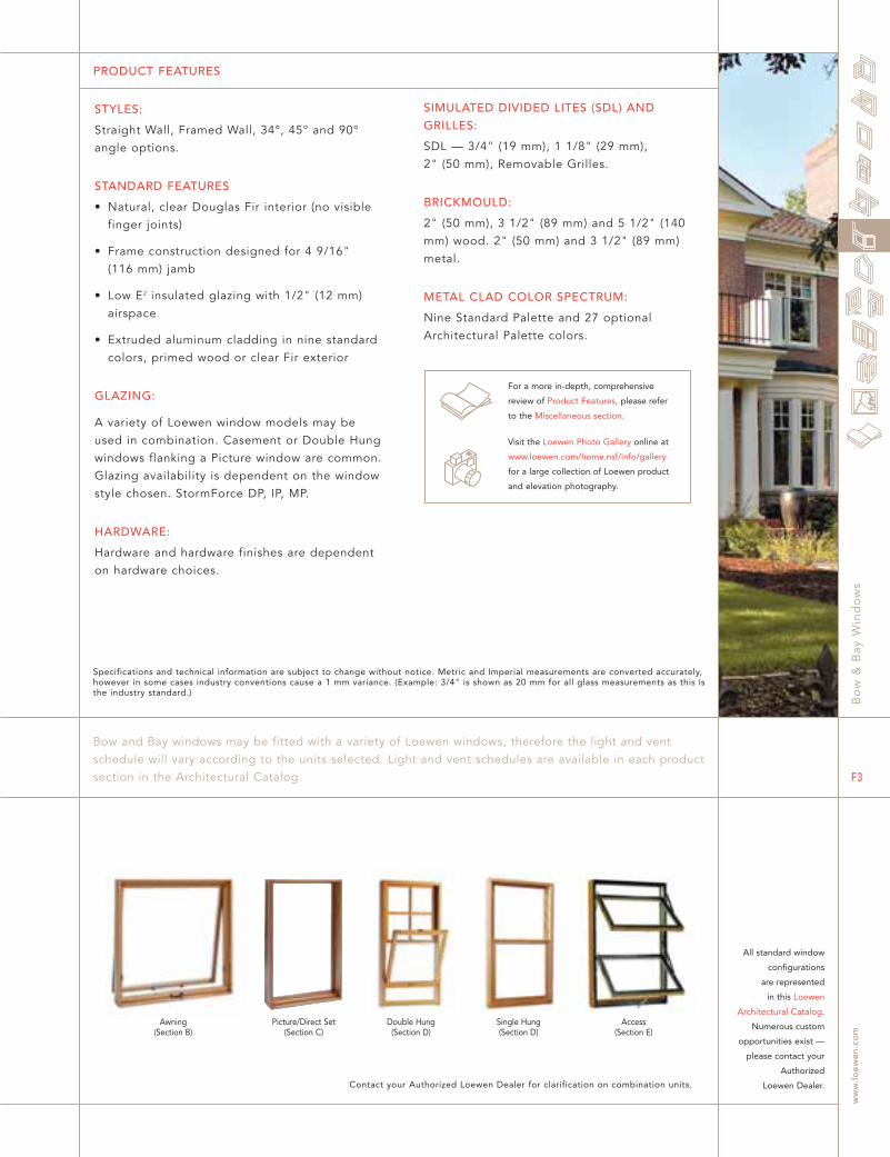
PRODUCT FEATURES
STYLES:
Straight Wall, Framed Wall, 34°, 45° and 90°angle options.
STANDARD FEATURES
• Natural, clear Douglas Fir interior (no visiblefinger joints)
• Frame construction designed for 4 9/16" (116 mm) jamb
• Low E2 insulated glazing with 1/2" (12 mm)airspace
• Extruded aluminum cladding in nine standardcolors, primed wood or clear Fir exterior
GLAZING:
A variety of Loewen window models may beused in combination. Casement or Double Hungwindows flanking a Picture window are common.Glazing availability is dependent on the windowstyle chosen. StormForce DP, IP, MP.
HARDWARE:
Hardware and hardware finishes are dependenton hardware choices.
SIMULATED DIVIDED LITES (SDL) ANDGRILLES:
SDL — 3/4" (19 mm), 1 1/8" (29 mm), 2" (50 mm), Removable Grilles.
BRICKMOULD:
2" (50 mm), 3 1/2" (89 mm) and 5 1/2" (140mm) wood. 2" (50 mm) and 3 1/2" (89 mm)metal.
METAL CLAD COLOR SPECTRUM:
Nine Standard Palette and 27 optionalArchitectural Palette colors.
Bo
w &
Bay
Win
do
ws
ww
w.l
oe
we
n.c
om
F3
Specifications and technical information are subject to change without notice. Metric and Imperial measurements are converted accurately,however in some cases industry conventions cause a 1 mm variance. (Example: 3/4" is shown as 20 mm for all glass measurements as this isthe industry standard.)
Contact your Authorized Loewen Dealer for clarification on combination units.
Bow and Bay windows may be fitted with a variety of Loewen windows, therefore the light and ventschedule will vary according to the units selected. Light and vent schedules are available in each productsection in the Architectural Catalog.
All standard window
configurations
are represented
in this Loewen
Architectural Catalog.
Numerous custom
opportunities exist —
please contact your
Authorized
Loewen Dealer.
For a more in-depth, comprehensive
review of Product Features, please refer
to the Miscellaneous section.
Visit the Loewen Photo Gallery online at
www.loewen.com/home.nsf/info/gallery
for a large collection of Loewen product
and elevation photography.
Double Hung(Section D)
Single Hung(Section D)
Picture/Direct Set(Section C)
Awning(Section B)
Access(Section E)
D4
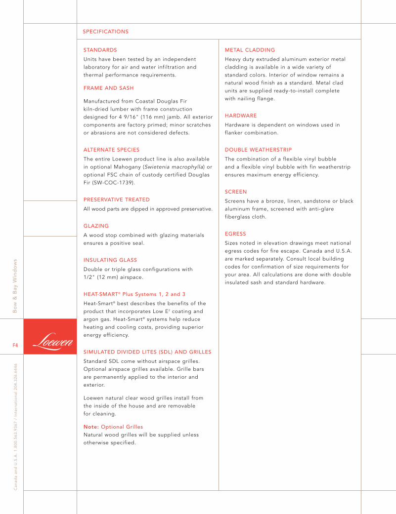
SPECIFICATIONS
STANDARDS
Units have been tested by an independentlaboratory for air and water infiltration andthermal performance requirements.
FRAME AND SASH
Manufactured from Coastal Douglas Fir kiln-dried lumber with frame constructiondesigned for 4 9/16" (116 mm) jamb. All exteriorcomponents are factory primed; minor scratchesor abrasions are not considered defects.
ALTERNATE SPECIES
The entire Loewen product line is also availablein optional Mahogany (Swietenia macrophylla) oroptional FSC chain of custody certified DouglasFir (SW-COC-1739).
PRESERVATIVE TREATED
All wood parts are dipped in approved preservative.
GLAZING
A wood stop combined with glazing materialsensures a positive seal.
INSULATING GLASS
Double or triple glass configurations with 1/2" (12 mm) airspace.
HEAT-SMART® Plus Systems 1, 2 and 3
Heat-Smart® best describes the benefits of theproduct that incorporates Low E2 coating andargon gas. Heat-Smart® systems help reduceheating and cooling costs, providing superiorenergy efficiency.
SIMULATED DIVIDED LITES (SDL) AND GRILLES
Standard SDL come without airspace grilles.Optional airspace grilles available. Grille barsare permanently applied to the interior andexterior.
Loewen natural clear wood grilles install from the inside of the house and are removable for cleaning.
Note: Optional GrillesNatural wood grilles will be supplied unless otherwise specified.
METAL CLADDING
Heavy duty extruded aluminum exterior metalcladding is available in a wide variety of standard colors. Interior of window remains anatural wood finish as a standard. Metal cladunits are supplied ready-to-install complete with nailing flange.
HARDWARE
Hardware is dependent on windows used inflanker combination.
DOUBLE WEATHERSTRIP
The combination of a flexible vinyl bubble and a flexible vinyl bubble with fin weatherstripensures maximum energy efficiency.
SCREEN
Screens have a bronze, linen, sandstone or blackaluminum frame, screened with anti-glarefiberglass cloth.
EGRESS
Sizes noted in elevation drawings meet nationalegress codes for fire escape. Canada and U.S.A.are marked separately. Consult local buildingcodes for confirmation of size requirements foryour area. All calculations are done with doubleinsulated sash and standard hardware.
Bo
w &
Bay
Win
do
ws
Can
ada
and
U.S
.A.
1.8
00
.56
3.9
36
7 /
In
tern
atio
nal
20
4.3
26
.64
46
F4

Projections: Framed Wall 2 x 4 = 10 9/16" (116 mm = 268 mm) or 2 x 6 = 10 9/16" (166 mm = 268 mm)
1459
57 7/16
1393
54 13/16
1659
65 5/16
1593
62 11/16
1859
73 3/16
1793
70 9/16
400 600 400 400 800 400 400 1000 400
40 1
/8
1019
1000
39 3
/8
BY3 1410 LFR BY3 1610 LFR BY3 1810 LFR
36 3
/16
919
900
35 7
/16
BY3 1409 LFR BY3 1609 LFR BY3 1809 LFR
Projections: Framed Wall 2 x 4 = 14 15/16" (116 mm = 380 mm) or 2 x 6 = 14 15/16" (166 mm = 380 mm)
2391
2325
91 1/2
94 1/8
2591
2525
99 3/8
102
2791
2725
107 1/4
109 7/8
2991
2925
115 1/8
117 3/4
48 1219
1200
47 1
/4
BY3 2412 LFR BY3 2612 LFR BY3 2812 LFR BY3 3012 LFR
55 7
/8
1419
1400
55 1
/8
BY3 2414 LFR BY3 2614 LFR BY3 2814 LFR BY3 3014 LFR
59 1
3/16
1519
1500
59 1
/16
BY3 2415 LFR BY3 2615 LFR BY3 2815 LFR BY3 3015 LFR
63 3
/4
1619
160063
BY3 2416 LFR BY3 2616 LFR BY3 2816 LFR BY3 3016 LFR
71 5
/8
1819
1800
70 7
/8
BY3 2418 LFR BY3 2618 LFR BY3 2818 LFR BY3 3018 LFR
600 1200 600 600 1400 600 600 1600 600 600 1800 600
UnitO.S.M.
FramedWallR.O.
in.
mm
in.
mm
UnitO.S.M.
FramedWallR.O.
in.
mm
in.
mm
34° KITCHEN BAY WINDOW - FRAMED WALL CASEMENT COMBINATIONS
34° BAY WINDOW - FRAMED WALL CASEMENT COMBINATIONS
BOW & BAY WINDOW ELEVATIONS
Bo
w &
Bay
Win
do
ws
ww
w.l
oe
we
n.c
om
F5
BBAY.E.001.0.2004
Note: • For glass sizes see Casement section.
• 3/4" (19 mm) plywood head and seat optional. If requested, add 1 1/2" (38 mm) to height R.O.
• All information is subject to HP1 glazing.
CAD DOWNLOAD: www.loewen.com/architect

Projections: Framed Wall 2 x 4 = 10 9/16" (116 mm = 268 mm) or 2 x 6 = 10 9/16" (166 mm = 268 mm)
Projections: Framed Wall 2 x 4 = 14 15/16" (116 mm = 380 mm) or 2 x 6 = 14 15/16" (166 mm = 380 mm)
UnitO.S.M.
FramedWallR.O.
in.
mm
in.
mm
UnitO.S.M.
FramedWallR.O.
in.
mm
in.
mm
1459
57 7/16
1393
54 13/16
1659
65 5/16
1593
62 11/16
1859
73 3/16
1793
70 5/8
40 1
/8
1019
1000
39 3
/8
BY3 1410 LPR BY3 1610 LPR BY3 1810 LPR
36 3
/16
919
900
35 7
/16
BY3 1409 LPR BY3 1609 LPR BY3 1809 LPR
400 600 400 400 800 400 400 1000 400
2391
2325
91 1/2
94 1/8
2591
2525
99 3/8
102
2791
2725
107 1/4
109 7/8
2991
2925
115 1/8
117 3/4
48 1219
1200
47 1
/4
BY3 2412 LPR BY3 2612 LPR BY3 2812 LPR BY3 3012 LPR
55 7
/8
1419
1400
55 1
/8
BY3 2414 LPR BY3 2614 LPR BY3 2814 LPR BY3 3014 LPR
59 1
3/16
1519
1500
59 1
/16
BY3 2415 LPR BY3 2615 LPR BY3 2815 LPR BY3 3015 LPR
63 3
/4
1619
160063
BY3 2416 LPR BY3 2616 LPR BY3 2816 LPR BY3 3016 LPR
71 5
/8
1819
1800
70 7
/8
BY3 2418 LPR BY3 2618 LPR BY3 2818 LPR BY3 3018 LPR
600 1200 600 600 1400 600 600 1600 600 600 1800 600
34° KITCHEN BAY WINDOW - FRAMED WALL CASEMENT/PICTURE COMBINATIONS
34° BAY WINDOW - FRAMED WALL CASEMENT/PICTURE COMBINATIONS
Bo
w &
Bay
Win
do
ws
Can
ada
and
U.S
.A.
1.8
00
.56
3.9
36
7 /
In
tern
atio
nal
20
4.3
26
.64
46
F6
BOW & BAY WINDOW ELEVATIONS
BBAY.E.002.0.2004
Note: • For glass sizes see Casement and Picture sections.
• 3/4" (19 mm) plywood head and seat optional. If requested, add 1 1/2" (38 mm) to height R.O.
• All information is subject to HP1 glazing.
CAD DOWNLOAD: www.loewen.com/architect

Projections: Framed Wall 2 x 4 = 13 11/16" (116 mm = 347 mm) or 2 x 6 = 13 11/16" (166 mm = 347 mm)
Projections: Framed Wall 2 x 4 = 19 1/4" (116 mm = 489 mm) or 2 x 6 = 19 1/4" (166 mm = 489 mm)
UnitO.S.M.
FramedWallR.O.
in.
mm
in.
mm
UnitO.S.M.
FramedWallR.O.
in.
mm
in.
mm
1381
54 3/8
1330
52 3/8
1581
62 1/4
1530
60 1/4
1781
70 1/8
1730
68 1/8
40 1
/8
1019
1000
39 3
/8
BY3 1410 LFR BY3 1610 LFR BY3 1810 LFR
36 3
/16
919
900
35 7
/16
BY3 1409 LFR BY3 1609 LFR BY3 1809 LFR
400 600 400 400 800 400 400 1000 400
2263
2213
87 1/8
89 1/8
2463
2413
95
97
2663
2613
102 7/8
104 7/8
2863
2813
110 3/4
112 3/4
48 1219
1200
47 1
/4
BY3 2412 LFR BY3 2612 LFR BY3 2812 LFR BY3 3012 LFR
55 7
/8
1419
1400
55 1
/8
BY3 2414 LFR BY3 2614 LFR BY3 2814 LFR BY3 3014 LFR
59 1
3/16
1519
1500
59 1
/16
BY3 2415 LFR BY3 2615 LFR BY3 2815 LFR BY3 3015 LFR
63 3
/4
1619
160063
BY3 2416 LFR BY3 2616 LFR BY3 2816 LFR BY3 3016 LFR
71 5
/8
1819
1800
70 7
/8
BY3 2418 LFR BY3 2618 LFR BY3 2818 LFR BY3 3018 LFR
600 1200 600 600 1400 600 600 1600 600 600 1800 600
45° KITCHEN BAY WINDOW - FRAMED WALL CASEMENT COMBINATIONS
45° BAY WINDOW - FRAMED WALL CASEMENT COMBINATIONS
BOW & BAY WINDOW ELEVATIONS
Bo
w &
Bay
Win
do
ws
ww
w.l
oe
we
n.c
om
F7
BBAY.E.003.0.2004
Note: • For glass sizes see Casement section.
• 3/4" (19 mm) plywood head and seat optional. If requested, add 1 1/2" (38 mm) to height R.O.
• All information is subject to HP1 glazing.
CAD DOWNLOAD: www.loewen.com/architect

UnitO.S.M.
FramedWallR.O.
in.
mm
in.
mm
UnitO.S.M.
FramedWallR.O.
in.
mm
in.
mm
Projections: Framed Wall 2 x 4 = 13 11/16" (116 mm = 347 mm) or 2 x 6 = 13 11/16" (166 mm = 347 mm)
Projections: Framed Wall 2 x 4 = 19 1/4" (116 mm = 489 mm) or 2 x 6 = 19 1/4" (166 mm = 489 mm)
1381
54 3/8
1330
52 3/8
1581
62 1/4
1530
60 1/4
1781
70 1/8
1730
68 1/8
40 1
/8
1019
1000
39 3
/8
BY3 1410 LPR BY3 1610 LPR BY3 1810 LPR
36 3
/16
919
900
35 7
/16
BY3 1409 LPR BY3 1609 LPR BY3 1809 LPR
400 600 400 400 800 400 400 1000 400
2263
2213
87 1/8
89 1/8
2463
2413
95
97
2663
2613
102 7/8
104 7/8
2863
2813
110 3/4
112 3/4
48 1219
1200
47 1
/4
BY3 2412 LPR BY3 2612 LPR BY3 2812 LPR BY3 3012 LPR
55 7
/8
1419
1400
55 1
/8
BY3 2414 LPR BY3 2614 LPR BY3 2814 LPR BY3 3014 LPR
59 1
3/16
1519
1500
59 1
/16
BY3 2415 LPR BY3 2615 LPR BY3 2815 LPR BY3 3015 LPR
63 3
/4
1619
160063
BY3 2416 LPR BY3 2616 LPR BY3 2816 LPR BY3 3016 LPR
71 5
/8
1819
1800
70 7
/8
BY3 2418 LPR BY3 2618 LPR BY3 2818 LPR BY3 3018 LPR
600 1200 600 600 1400 600 600 1600 600 600 1800 600
45° KITCHEN BAY WINDOW - FRAMED WALL CASEMENT/PICTURE COMBINATIONS
45° BAY WINDOW - FRAMED WALL CASEMENT/PICTURE COMBINATIONS
Bo
w &
Bay
Win
do
ws
Can
ada
and
U.S
.A.
1.8
00
.56
3.9
36
7 /
In
tern
atio
nal
20
4.3
26
.64
46
F8
BOW & BAY WINDOW ELEVATIONS
BBAY.E.004.0.2004
Note: • For glass sizes see Casement and Picture sections.
• 3/4" (19 mm) plywood head and seat optional. If requested, add 1 1/2" (38 mm) to height R.O.
• All information is subject to HP1 glazing.
CAD DOWNLOAD: www.loewen.com/architect

Projections:
UnitO.S.M.
FramedWallR.O.
in.
mm
in.
mm 2501
2415
95 1/16
98 7/16
3071
2989
117 11/16
120 7/8
2501
2415
95 1/16
98 7/16
3071
2989
117 11/16
120 7/8
36 3
/16
919
900
35 7
/16
BW4 2409 LPPR BW5 3009 LPPPRBW4 2409 LFFR BW5 3009 LFFFR
40 1
/8
1019
1000
39 3
/8
BW4 2410 LPPR BW5 3010 LPPPRBW4 2410 LFFR BW5 3010 LFFFR
48 1219
1200
47 1
/4
BW4 2412 LPPR BW5 3012 LPPPRBW4 2412 LFFR BW5 3012 LFFFR
55 7
/8
1419
1400
55 1
/8
BW4 2414 LPPR BW5 3014 LPPPRBW4 2414 LFFR BW5 3014 LFFFR
59 1
3/16
1519
1500
59 1
/16
BW4 2415 LPPR BW5 3015 LPPPRBW4 2415 LFFR BW5 3015 LFFFR
63 3
/4
1619
160063
BW4 2416 LPPR BW5 3016 LPPPRBW4 2416 LFFR BW5 3016 LFFFR
71 5
/8
1819
1800
70 7
/8
BW4 2418 LPPR BW5 3018 LPPPRBW4 2418 LFFR BW5 3018 LFFFR
2 x 4 = 8 13/16"(116 mm = 224 mm)
2 x 6 = 8 13/16"(166 mm = 224 mm)
2 x 4 = 13 1/16"(116 mm = 332 mm)
2 x 6 = 13 1/16"(166 mm = 332 mm)
10˚ BOW WINDOW COMBINATIONS
BOW & BAY WINDOW ELEVATIONS
Bo
w &
Bay
Win
do
ws
ww
w.l
oe
we
n.c
om
F9
BBAY.E.005.0.2004
Note: • For glass sizes see Casement and Picture sections.
• 3/4" (19 mm) plywood head and seat optional. If requested, add 1 1/2" (38 mm) to height R.O.
• Single units are 23 5/8" (600 mm) wide.
• All information is subject to HP1 glazing.
CAD DOWNLOAD: www.loewen.com/architect

ROUGH OPENING
A
PROJECTION
THIS STUD TO BE EXTENDED TO PLATE
45°
THESE STUDS TO BE EXTENDED TO HEADER
A
ROUGH OPENING
PROJECTION
34°
A
THIS STUD TO BE EXTENDED TO PLATE
ROUGH OPENING C
B D
THESE STUDS TO BE EXTENDED TO HEADER
10°
ROUGH OPENING
A C
B D
THIS STUD TO BE EXTENDED TO PLATE
THESE STUDS TO BE EXTENDED TO HEADER
10°
Note: • Framed wall Bay windows are supplied without head and seat.
• Add 3/4" (19 mm) to Rough Opening height for optional head or seat.
• Add 1 1/2" (38 mm) to Rough Opening height for optional plywood head & seat.
Note: • Add 3/4" (19 mm) to Rough Opening height for optional head or seat.
• Add 1 1/2" (38 mm) to Rough Opening height for optional plywood head & seat.
FRAMED WALL BOW CONSTRUCTION DETAIL
FRAMED WALL BAY CONSTRUCTION DETAIL
Four Section Bow Window
FRAMING MEASUREMENTS FOR STANDARD 23 5/8" (600 mm) UNITS
Five Section Bow Window
DESCRIPTION
ROUGH OPENING WIDTH HEADER LENGTH A MEASUREMENT B MEASUREMENT C MEASUREMENT D MEASUREMENT
mm
3069 3145 641 227 1234 332
4 9/16" (116 mm) JAMB
in.
120 13/16" 123 13/16" 25 3/4" 9" 48 3/4" 13 1/16"
in.
120 13/16" 123 13/16" 25 1/4" 8 15/16" 48 9/16" 13 1/16"
mm
3069 3145 654 229 1238 332
6 9/16" (166 mm) JAMB
FRAMING MEASUREMENTS FOR STANDARD 23 5/8" (600 mm) UNITS
DESCRIPTION
ROUGH OPENING WIDTH HEADER LENGTH A MEASUREMENT B MEASUREMENT C MEASUREMENT D MEASUREMENT
mm
2500 2576 651 171 1250 224
4 9/16" (116 mm) JAMB
in.
98 7/16" 101 7/16" 25 15/16" 6 3/4" 49 3/16" 8 3/4"
in.
98 7/16" 101 7/16" 25 5/8" 6 3/4" 49 3/16" 8 13/16"
mm
2500 2576 659 172 1250 223
6 9/16" (166 mm) JAMB
45° FRAMING MEASUREMENTS - 23 5/8" (600 mm) FLANKERS
DESCRIPTION
A MEASUREMENT PROJECTION
mm
526 488
4 9/16" (116 mm) JAMB
in.
20 9/16" 19 3/16"
in.
20 11/16" 19 3/16"
mm
547 488
6 9/16" (166 mm) JAMB
34° FRAMING MEASUREMENTS - 23 5/8" (600 mm) FLANKERS
DESCRIPTION
A MEASUREMENT PROJECTION
mm
591 380
4 9/16" (116 mm ) JAMB
in.
23 7/8" 14 15/16"
in.
23 1/4" 14 15/16"
mm
606 380
6 9/16" (166 mm ) JAMB
• Other jamb widths available.
BOW AND BAY WINDOW CONSTRUCTION DETAILS
Bo
w &
Bay
Win
do
ws
Can
ada
and
U.S
.A.
1.8
00
.56
3.9
36
7 /
In
tern
atio
nal
20
4.3
26
.64
46
F10
BOW & BAY WINDOW DETAILS
BBAY.D.013.0.2004 CAD DOWNLOAD: www.loewen.com/architect
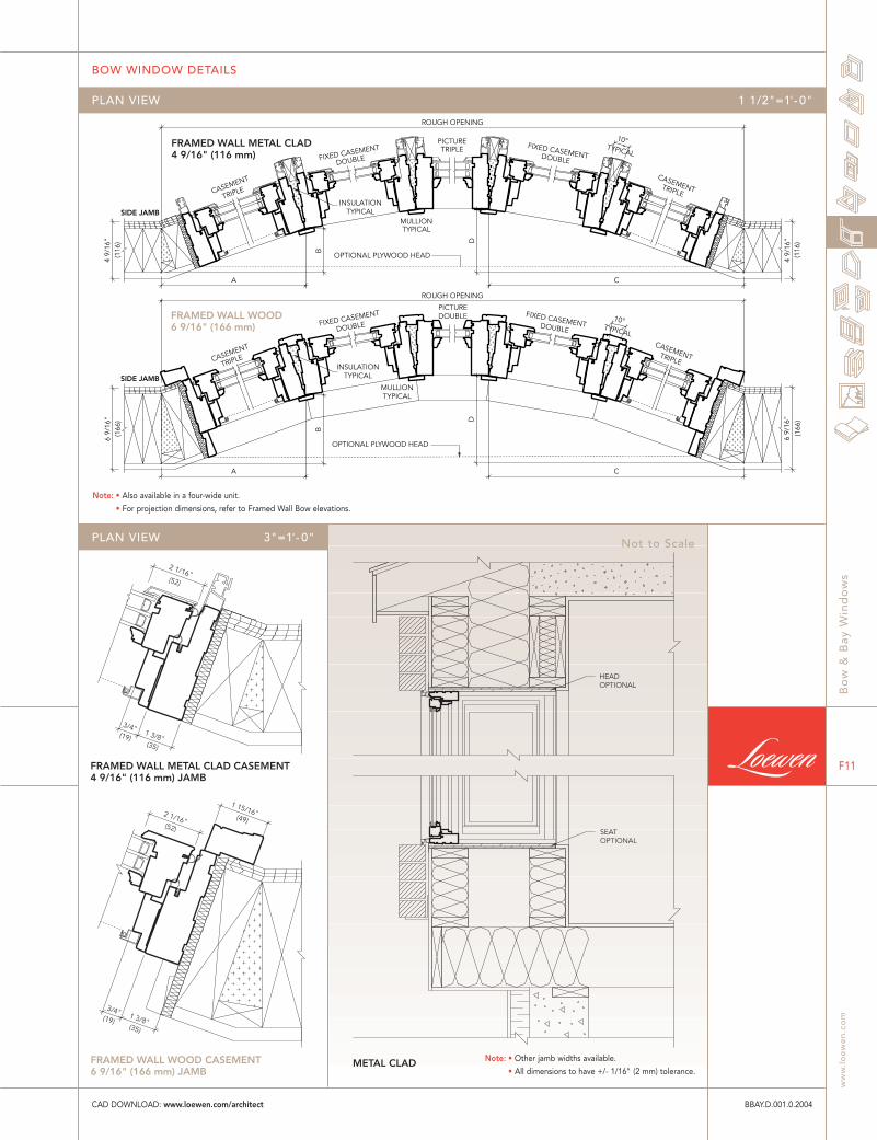
FRAMED WALL METAL CLAD4 9/16" (116 mm)
FRAMED WALL WOOD6 9/16" (166 mm)
INSULATIONTYPICALSIDE JAMB
MULLIONTYPICAL
SIDE JAMB
OPTIONAL PLYWOOD HEAD
INSULATIONTYPICAL
OPTIONAL PLYWOOD HEAD
MULLIONTYPICAL
CASEMENT
TRIPLE
FIXED CASEMENT
DOUBLE
PICTURETRIPLE FIXED CASEMENTDOUBLE
CASEMENTTRIPLE
TYPICAL
TYPICAL
CASEMENT
TRIPLE
FIXED CASEMENT
DOUBLE
PICTUREDOUBLE FIXED CASEMENTDOUBLE
CASEMENTTRIPLE
(116
)4
9/16
"(1
66)
6 9/
16"
(116
)4
9/16
"(1
66)
6 9/
16"
10°
B
A
D
C
ROUGH OPENING
10°
ROUGH OPENING
B
AD
C
(19) (35)
(52)
2 1/16"
1 3/8"
3/4"
(52)
(19) (35)
(49) 2 1/16"
1 15/16"
1 3/8"
3/4"
FRAMED WALL METAL CLAD CASEMENT 4 9/16" (116 mm) JAMB
FRAMED WALL WOOD CASEMENT 6 9/16" (166 mm) JAMB
HEAD OPTIONAL
SEAT OPTIONAL
METAL CLAD
PLAN VIEW 3"=1'- 0"
BOW WINDOW DETAILS
Bo
w &
Bay
Win
do
ws
ww
w.l
oe
we
n.c
om
F11
BBAY.D.001.0.2004
PLAN VIEW 1 1/2"=1'- 0"
Not to Scale
CAD DOWNLOAD: www.loewen.com/architect
Note: • Also available in a four-wide unit.
• For projection dimensions, refer to Framed Wall Bow elevations.
Note: • Other jamb widths available.
• All dimensions to have +/- 1/16" (2 mm) tolerance.
(52)
(19) (35)
2 1/16"
3/4" 1 3/8"
CASEMENT TRIPLE
HEA
D H
EAD
CASEMENT
TRIPLE
OPTIONAL PLYWOOD HEAD
MULLION TYPICAL
INSULATION TYPICAL
SIDE JAMB
(116
)
4 9/
16"
FIXED CASEMENT DOUBLE
ROUGH OPENING (1
16)
4 9/
16"
A
PRO
JEC
TIO
N
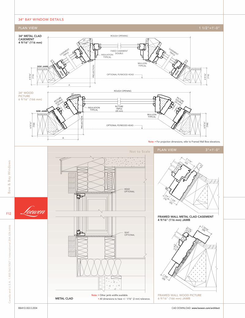
34° METAL CLAD CASEMENT 4 9/16" (116 mm)
FRAMED WALL METAL CLAD CASEMENT 4 9/16" (116 mm) JAMB
HEAD OPTIONAL
SEAT OPTIONAL
METAL CLAD FRAMED WALL WOOD PICTURE 6 9/16" (166 mm) JAMB
34° WOOD PICTURE 6 9/16" (166 mm)
TYPICAL 34°
(49)(17)
(17)
(35)
1 15/16"11/16"
11/16"
1 3/8"
PICTURETRIPLE(35 mm)
PICTUREDOUBLE
(35 mm)
PICTURE
DOUBLE
(35 mm)
INSULATIONTYPICAL
MULLIONTYPICAL
OPTIONAL PLYWOOD HEAD
SIDE JAMB
TYPICAL
(166
)
6 9/
16"
(166
)6
9/16
"
A
PRO
JEC
TIO
N
ROUGH OPENING
34°
Bo
w &
Bay
Win
do
ws
Can
ada
and
U.S
.A.
1.8
00
.56
3.9
36
7 /
In
tern
atio
nal
20
4.3
26
.64
46
F12
34° BAY WINDOW DETAILS
BBAY.D.002.0.2004
PLAN VIEW 1 1/2"=1'- 0"
PLAN VIEW 3"=1'- 0"Not to Scale
CAD DOWNLOAD: www.loewen.com/architect
Note: • For projection dimensions, refer to Framed Wall Bow elevations.
Note: • Other jamb widths available.
• All dimensions to have +/- 1/16" (2 mm) tolerance.

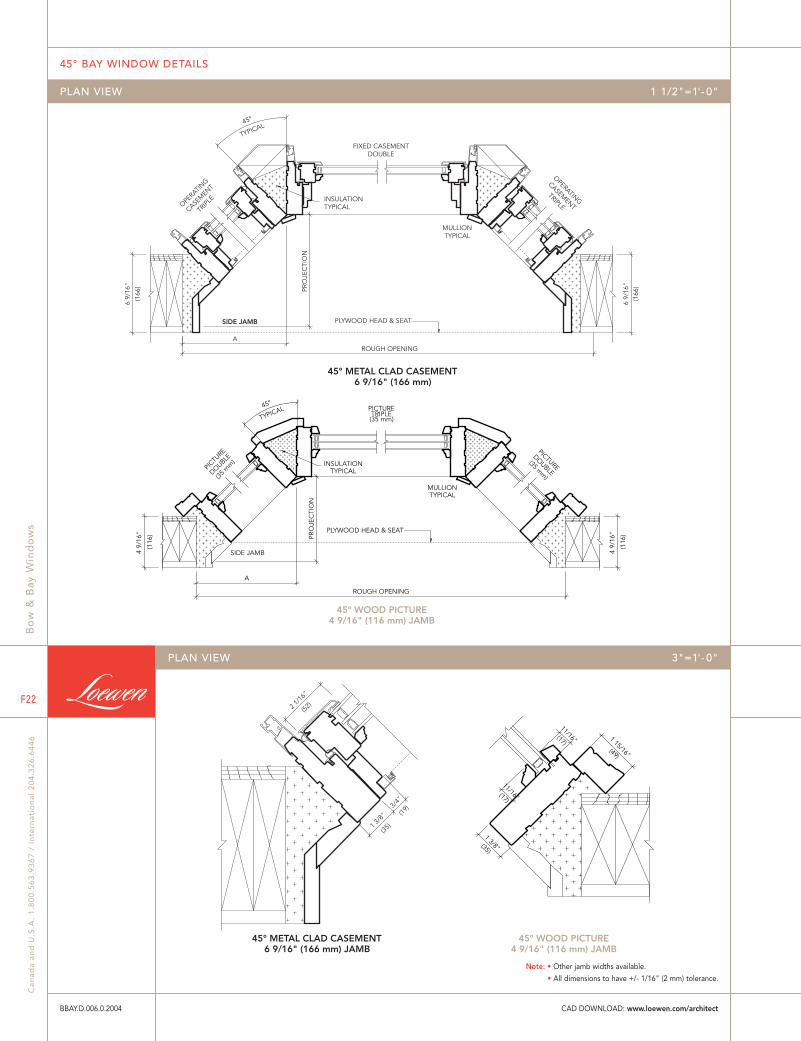
45° METAL CLAD CASEMENT 6 9/16" (166 mm)
OPTIONAL PLYWOOD HEAD
TYPICAL
MULLION TYPICAL
SIDE JAMB
INSULATION TYPICAL
FIXED CASEMENT DOUBLE
CASEM
ENT
TRIPL
E
CASEMENT
TRIPLE
45°
(166
)
6 9/
16"
(166
)
6 9/
16"
A ROUGH OPENING
PRO
JEC
TIO
N
45° WOOD PICTURE 4 9/16" (116 mm) JAMB
OPTIONAL PLYWOOD HEAD
TYPICAL
MULLIONTYPICAL
SIDE JAMB
INSULATIONTYPICAL
PICTURETRIPLE(35 mm)
PICTU
RE
DOUBLE
(35 m
m)
PICTURE
DOUBLE(35 mm)
45°
(116
)4
9/16
"
(116
)4
9/16
"
AROUGH OPENING
PRO
JEC
TIO
N
45° WOOD PICTURE 4 9/16" (116 mm) JAMB
45° METAL CLAD CASEMENT 6 9/16" (166 mm) JAMB
(52)
(35)
(19)
1 3/8
"
3/4"
2 1/1
6"
(49)
(17)
(35)
1 15/16"
11/16"
11/16"
1 3/8"
(17)
45° BAY WINDOW DETAILS
Bo
w &
Bay
Win
do
ws
ww
w.l
oe
we
n.c
om
F13
BBAY.D.003.0.2004
PLAN VIEW 1 1/2"=1'- 0"
PLAN VIEW 3"=1'- 0"
CAD DOWNLOAD: www.loewen.com/architect
Note: • Other jamb widths available.
• All dimensions to have +/- 1/16" (2 mm) tolerance.

UnitO.S.M.
StraightWallR.O.
in.
mm
in.
mm
UnitO.S.M.
StraightWallR.O.
in.
mm
in.
mm
Projections: Framed Wall 2 x 4 = 9 13/16" (116 mm = 250 mm) or 2 x 6 = 11 13/16" (166 mm = 300 mm)
Projections: Framed Wall 2 x 4 = 14 1/4" (116 mm = 362 mm) or 2 x 6 = 16 1/4" (166 mm = 412 mm)
1384
54 1/2
1390
54 11/16
1584
62 3/8
1590
62 9/16
1784
70 1/4
1790
70 7/16
BY3 1410 LFR BY3 1610 LFR
41 5
/8
1058
1000
39 3
/8
BY3 1810 LFR
37 1
1/16
958
900
35 7
/16
BY3 1409 LFR BY3 1609 LFR BY3 1809 LFR
400 600 400 400 800 400 400 1000 400
2316
2321
91 3/8
91 3/16
2516
2521
99 1/4
99 1/16
2716
2721
107 1/8
106 15/16
2916
2921
115
114 13/16
49 1
/2
1258
1200
47 1
/4
BY3 2412 LFR BY3 2612 LFR BY3 2812 LFR BY3 3012 LFR
57 3
/8
1458
1400
55 1
/8
BY3 2414 LFR BY3 2614 LFR BY3 2814 LFR BY3 3014 LFR
61 5
/16
1558
1500
59 1
/16
BY3 2415 LFR BY3 2615 LFR BY3 2815 LFR BY3 3015 LFR
65 1
/4
1658
160063
BY3 2416 LFR BY3 2616 LFR BY3 2816 LFR BY3 3016 LFR
73 1
/8
1858
1800
70 7
/8
BY3 2418 LFR BY3 2618 LFR BY3 2818 LFR BY3 3018 LFR
600 1200 600 600 1400 600 600 1600 600 600 1800 600
34° KITCHEN BAY WINDOW - STRAIGHT WALL CASEMENT COMBINATIONS
34° BAY WINDOW - STRAIGHT WALL CASEMENT COMBINATIONS
Bo
w &
Bay
Win
do
ws
Can
ada
and
U.S
.A.
1.8
00
.56
3.9
36
7 /
In
tern
atio
nal
20
4.3
26
.64
46
F14
BOW & BAY WINDOW ELEVATIONS
BBAY.E.007.0.2004
Note: • For glass sizes see Casement section.
• 3/4" (19 mm) plywood head and seat optional. If requested, add 1 1/2" (38 mm) to height R.O.
• All information is subject to HP1 glazing.
CAD DOWNLOAD: www.loewen.com/architect

Projections: Framed Wall 2 x 4 = 9 13/16" (116 mm = 250 mm) or 2 x 6 = 11 13/16" (166 mm = 300 mm)
Projections: Framed Wall 2 x 4 = 14 1/4" (116 mm = 362 mm) or 2 x 6 = 16 1/4" (166 mm = 412 mm)
UnitO.S.M.
StraightWallR.O.
in.
mm
in.
mm
UnitO.S.M.
StraightWallR.O.
in.
mm
in.
mm
1384
54 1/2
1390
54 11/16
1584
62 3/8
1590
62 9/16
1784
70 1/4
1790
70 7/16
41 5
/8
1058
1000
39 3
/8
BY3 1410 LPR BY3 1610 LPR BY3 1810 LPR
37 1
1/16
958
900
35 7
/16
BY3 1409 LPR BY3 1609 LPR BY3 1809 LPR
400 600 400 400 800 400 400 1000 400
2316
2321
91 3/8
91 3/16
2516
2521
99 1/4
99 1/16
2716
2721
107 1/8
106 15/16
2916
2921
115
114 13/16
49 1
/2
1258
1200
47 1
/4
BY3 2412 LPR BY3 2612 LPR BY3 2812 LPR BY3 3012 LPR
57 3
/8
1458
1400
55 1
/8
BY3 2414 LPR BY3 2614 LPR BY3 2814 LPR BY3 3014 LPR
61 5
/16
1558
1500
59 1
/16
BY3 2415 LPR BY3 2615 LPR BY3 2815 LPR BY3 3015 LPR
65 1
/4
1658
160063
BY3 2416 LPR BY3 2616 LPR BY3 2816 LPR BY3 3016 LPR
73 1
/8
1858
1800
70 7
/8
BY3 2418 LPR BY3 2618 LPR BY3 2818 LPR BY3 3018 LPR
600 1200 600 600 1400 600 600 1600 600 600 1800 600
34° KITCHEN BAY WINDOW - STRAIGHT WALL CASEMENT/PICTURE COMBINATIONS
34° BAY WINDOW - STRAIGHT WALL CASEMENT/PICTURE COMBINATIONS
BOW & BAY WINDOW ELEVATIONS
Bo
w &
Bay
Win
do
ws
ww
w.l
oe
we
n.c
om
F15
BBAY.E.008.0.2004
Note: • For glass sizes see Casement and Picture sections.
• 3/4" (19 mm) plywood head and seat optional. If requested, add 1 1/2" (38 mm) to height R.O.
• All information is subject to HP1 glazing.
CAD DOWNLOAD: www.loewen.com/architect
Projections: Framed Wall 2 x 4 = 12 15/16" (116 mm = 329 mm) or 2 x 6 = 14 15/16" (166 mm = 379 mm)
Projections: Framed Wall 2 x 4 = 18 1/2" (116 mm = 470 mm) or 2 x 6 = 20 1/2" (166 mm = 520 mm)
UnitO.S.M.
StraightWallR.O.
in.
mm
in.
mm
UnitO.S.M.
StraightWallR.O.
in.
mm
in.
mm
1299
51 1/8
1325
52 3/16
1499
59
1525
60 1/16
1699
66 7/8
1725
67 15/16
41 5
/8
1058
1000
39 3
/8
BY3 1410 LFR BY3 1610 LFR BY3 1810 LFR
37 1
1/16
958
900
35 7
/16
BY3 1409 LFR BY3 1609 LFR BY3 1809 LFR
400 600 400 400 800 400 400 1000 400
2181
2208
86 15/16
85 7/8
2381
2408
94 13/16
93 3/4
2581
2608
102 11/16
101 5/8
2781
2808
110 9/16
109 1/2
49 1
/2
1258
1200
47 1
/4
BY3 2412 LFR BY3 2612 LFR BY3 2812 LFR BY3 3012 LFR
57 3
/8
1458
1400
55 1
/8
BY3 2414 LFR BY3 2614 LFR BY3 2814 LFR BY3 3014 LFR
61 5
/16
1558
1500
59 1
/16
BY3 2415 LFR BY3 2615 LFR BY3 2815 LFR BY3 3015 LFR
65 1
/4
1658
160063
BY3 2416 LFR BY3 2616 LFR BY3 2816 LFR BY3 3016 LFR
73 1
/8
1858
1800
70 7
/8
BY3 2418 LFR BY3 2618 LFR BY3 2818 LFR BY3 3018 LFR
600 1200 600 600 1400 600 600 1600 600 600 1800 600
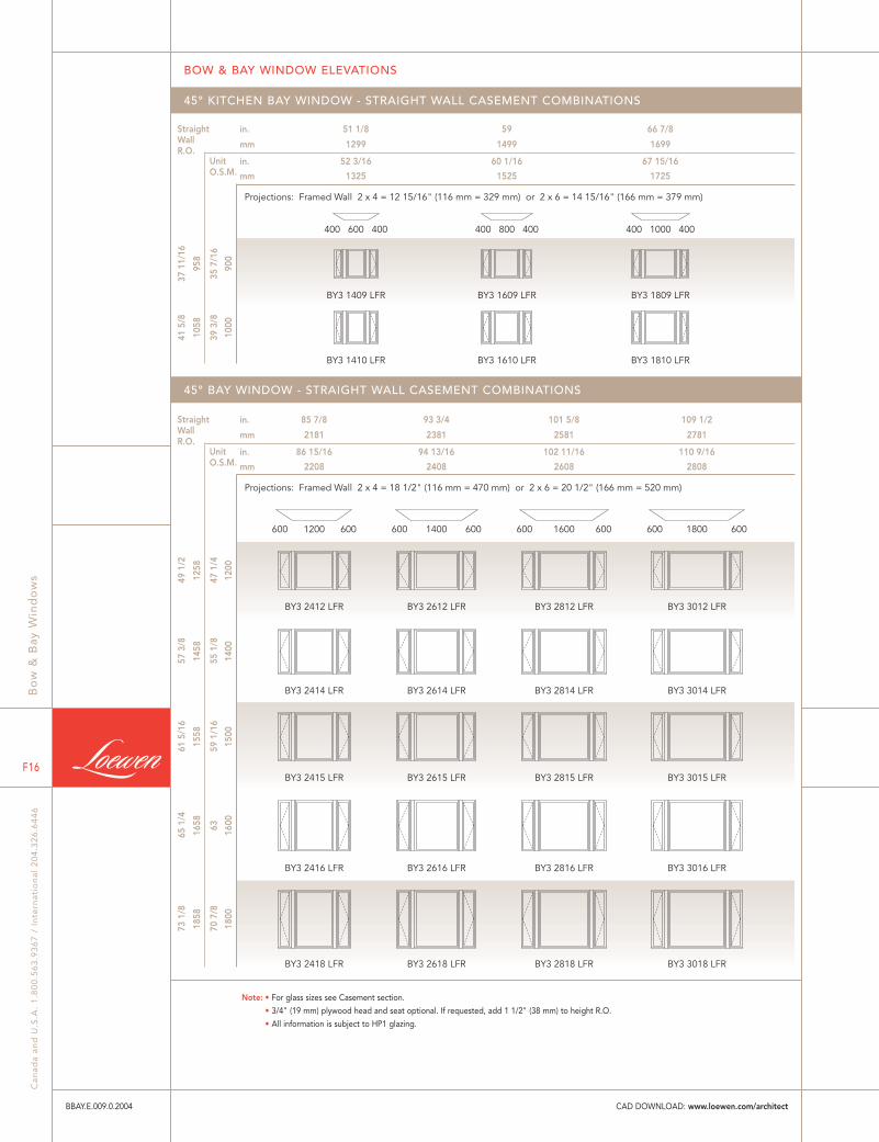
45° KITCHEN BAY WINDOW - STRAIGHT WALL CASEMENT COMBINATIONS
45° BAY WINDOW - STRAIGHT WALL CASEMENT COMBINATIONS
Bo
w &
Bay
Win
do
ws
Can
ada
and
U.S
.A.
1.8
00
.56
3.9
36
7 /
In
tern
atio
nal
20
4.3
26
.64
46
F16
BOW & BAY WINDOW ELEVATIONS
BBAY.E.009.0.2004
Note: • For glass sizes see Casement section.
• 3/4" (19 mm) plywood head and seat optional. If requested, add 1 1/2" (38 mm) to height R.O.
• All information is subject to HP1 glazing.
CAD DOWNLOAD: www.loewen.com/architect
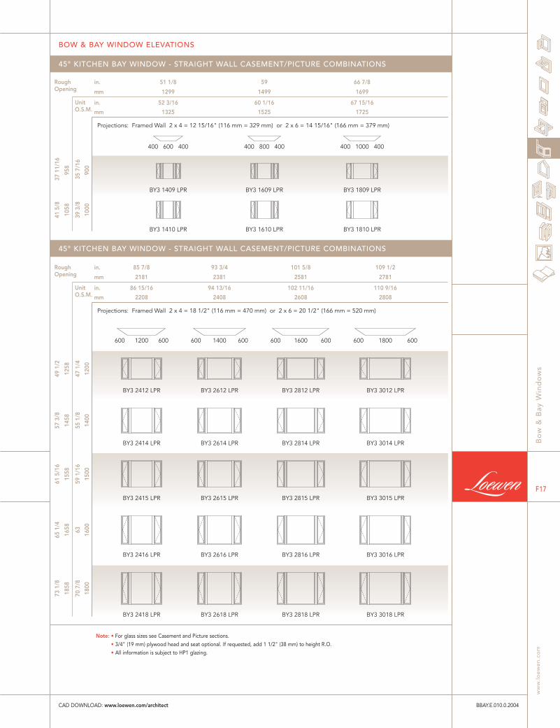
Projections: Framed Wall 2 x 4 = 12 15/16" (116 mm = 329 mm) or 2 x 6 = 14 15/16" (166 mm = 379 mm)
Projections: Framed Wall 2 x 4 = 18 1/2" (116 mm = 470 mm) or 2 x 6 = 20 1/2" (166 mm = 520 mm)
UnitO.S.M.
RoughOpening
in.
mm
in.
mm
UnitO.S.M.
RoughOpening
in.
mm
in.
mm
1299
51 1/8
1325
52 3/16
1499
59
1525
60 1/16
1699
66 7/8
1725
67 15/16
41 5
/8
1058
1000
39 3
/8
BY3 1410 LPR BY3 1610 LPR BY3 1810 LPR
37 1
1/16
958
900
35 7
/16
BY3 1409 LPR BY3 1609 LPR BY3 1809 LPR
400 600 400 400 800 400 400 1000 400
2181
2208
86 15/16
85 7/8
2381
2408
94 13/16
93 3/4
2581
2608
102 11/16
101 5/8
2781
2808
110 9/16
109 1/2
49 1
/2
1258
1200
47 1
/4
BY3 2412 LPR BY3 2612 LPR BY3 2812 LPR BY3 3012 LPR
57 3
/8
1458
1400
55 1
/8
BY3 2414 LPR BY3 2614 LPR BY3 2814 LPR BY3 3014 LPR
61 5
/16
1558
1500
59 1
/16
BY3 2415 LPR BY3 2615 LPR BY3 2815 LPR BY3 3015 LPR
65 1
/4
1658
160063
BY3 2416 LPR BY3 2616 LPR BY3 2816 LPR BY3 3016 LPR
73 1
/8
1858
1800
70 7
/8
BY3 2418 LPR BY3 2618 LPR BY3 2818 LPR BY3 3018 LPR
600 1200 600 600 1400 600 600 1600 600 600 1800 600
45° KITCHEN BAY WINDOW - STRAIGHT WALL CASEMENT/PICTURE COMBINATIONS
45° KITCHEN BAY WINDOW - STRAIGHT WALL CASEMENT/PICTURE COMBINATIONS
BOW & BAY WINDOW ELEVATIONS
Bo
w &
Bay
Win
do
ws
ww
w.l
oe
we
n.c
om
F17
BBAY.E.010.0.2004
Note: • For glass sizes see Casement and Picture sections.
• 3/4" (19 mm) plywood head and seat optional. If requested, add 1 1/2" (38 mm) to height R.O.
• All information is subject to HP1 glazing.
CAD DOWNLOAD: www.loewen.com/architect

Projections:
2428
2413
95
95 9/16
2997
2987
117 9/16
118
2428
2413
95
95 9/16
2997
2987
117 9/16
118
2 x 4 = 8 3/16"(116 mm = 208 mm)
2 x 6 = 10 3/16"(166 mm = 258 mm)
37 1
1/16
958
900
35 7
/16
BW4 2409 LPPR BW5 3009 LPPPRBW4 2409 LFFR BW5 3009 LFFFR
41 5
/8
1058
1000
39 3
/8
BW4 2410 LPPR BW5 3010 LPPPRBW4 2410 LFFR BW5 3010 LFFFR
49 1
/2
1258
1200
47 1
/4
BW4 2412 LPPR BW5 3012 LPPPRBW4 2412 LFFR BW5 3012 LFFFR
57 3
/8
1458
1400
55 1
/8
BW4 2414 LPPR BW5 3014 LPPPRBW4 2414 LFFR BW5 3014 LFFFR
61 5
/16
1558
1500
59 1
/16
BW4 2415 LPPR BW5 3015 LPPPRBW4 2415 LFFR BW5 3015 LFFFR
65 1
/4
1658
160063
BW4 2416 LPPR BW5 3016 LPPPRBW4 2416 LFFR BW5 3016 LFFFR
73 1
/8
1858
1800
70 7
/8
BW4 2418 LPPR BW5 3018 LPPPRBW4 2418 LFFR BW5 3018 LFFFR
2 x 4 = 12 7/16"(116 mm = 316 mm)
2 x 6 = 14 7/16"(166 mm = 366 mm)
UnitO.S.M.
StraightWallR.O.
in.
mm
in.
mm
10˚ BOW WINDOW COMBINATIONS
Bo
w &
Bay
Win
do
ws
Can
ada
and
U.S
.A.
1.8
00
.56
3.9
36
7 /
In
tern
atio
nal
20
4.3
26
.64
46
F18
BOW & BAY WINDOW ELEVATIONS
BBAY.E.011.0.2004
Note: • For glass sizes see Casement and Picture sections.
• 3/4" (19 mm) plywood head and seat optional. If requested, add 1 1/2" (38 mm) to height R.O.
• Single units are 23 5/8" (600 mm) wide.
• All information is subject to HP1 glazing.
CAD DOWNLOAD: www.loewen.com/architect
ROUGH OPENING
PROJECTION
45°
PROJECTION
ROUGH OPENING
34°
THIS STUD TO BE EXTENDED TO PLATE
THESE STUDS TO BE EXTENDED TO HEADER
A
ROUGH OPENING C
B D
ROUGH OPENING
A C
B D
10°
10°
THIS STUD TO BE EXTENDED TO PLATE
THESE STUDS TO BE EXTENDED TO HEADER
THIS STUD TO BE EXTENDED TO PLATE
THESE STUDS TO BE EXTENDED TO HEADER
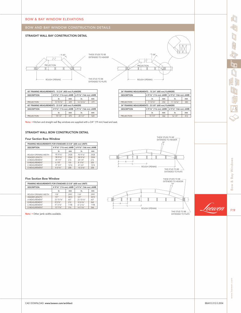
Note: • Kitchen and straight wall Bay windows are supplied with a 3/4" (19 mm) head and seat.
STRAIGHT WALL BOW CONSTRUCTION DETAIL
STRAIGHT WALL BAY CONSTRUCTION DETAIL
Four Section Bow Window
FRAMING MEASUREMENTS FOR STANDARD 23 5/8" (600 mm) UNITS
Five Section Bow Window
DESCRIPTION
ROUGH OPENING WIDTH HEADER LENGTH A MEASUREMENT B MEASUREMENT C MEASUREMENT D MEASUREMENT
mm
2997 3073 607 212 1198 316
4 9/16" (116 mm) JAMB
in.
118" 121" 23 15/16" 10 5/16" 47 3/16" 14 7/16"
in.
118" 121" 23 15/16" 8 5/16" 47 3/16" 12 7/16"
mm
2997 3073 607 262 1198 366
6 9/16" (166 mm) JAMB
FRAMING MEASUREMENTS FOR STANDARD 23 5/8" (600 mm) UNITS
DESCRIPTION
ROUGH OPENING WIDTH HEADER LENGTH A MEASUREMENT B MEASUREMENT C MEASUREMENT D MEASUREMENT
mm
2428 2504 616 155 1214 208
4 9/16" (116 mm) JAMB
in.
95 9/16" 98 9/16" 24 1/4" 8 1/16" 47 3/4" 10 3/16"
in.
95 9/16" 98 9/16" 24 1/4" 6 1/8" 47 3/4" 8 3/16"
mm
2428 2504 616 205 1214 258
6 9/16" (166 mm) JAMB
45° FRAMING MEASUREMENTS - 15 3/4" (400 mm) FLANKERS
DESCRIPTION
PROJECTION
mm
329
4 9/16" (116 mm) JAMB
in.
14 15/16"
in.
12 15/16"
mm
379
6 9/16" (166 mm) JAMB
45° FRAMING MEASUREMENTS - 23 5/8" (600 mm) FLANKERS
DESCRIPTION
PROJECTION
mm
470
4 9/16" (116 mm) JAMB
in.
20 1/2"
in.
18 1/2"
mm
520
6 9/16" (166 mm) JAMB
34° FRAMING MEASUREMENTS - 15 3/4" (400 mm) FLANKERS
DESCRIPTION
PROJECTION
mm
250
4 9/16" (116 mm) JAMB
in.
11 13/16"
in.
9 13/16"
mm
300
6 9/16" (166 mm) JAMB
34° FRAMING MEASUREMENTS - 23 5/8" (600 mm) FLANKERS
DESCRIPTION
PROJECTION
mm
362
4 9/16" (116 mm) JAMB
in.
16 1/4"
in.
14 1/4"
mm
412
6 9/16" (166 mm) JAMB
BOW AND BAY WINDOW CONSTRUCTION DETAILS
BOW & BAY WINDOW ELEVATIONS
Bo
w &
Bay
Win
do
ws
ww
w.l
oe
we
n.c
om
F19
BBAY.E.012.0.2004CAD DOWNLOAD: www.loewen.com/architect
Note: • Other jamb widths available.

STRAIGHT WALL METAL CLAD CASEMENT 4 9/16" (116 mm) JAMB
STRAIGHT WALL WOOD CASEMENT 6 9/16" (166 mm) JAMB
STRAIGHT WALL METAL CLAD 4 9/16" (116 mm)
STRAIGHT WALL WOOD 6 9/16" (166 mm)
(19) (35)
2 1/16"
3/4" 1 3/8"
(52)
(19) (35)
(49)
2 1/16"
3/4" 1 3/8"
1 15/16"
WOOD
OPTIONAL CABLE SUPPORT SYSTEM
(166
)
INSULATIONTYPICALSIDE JAMB
SIDE JAMB
PLYWOOD HEAD & SEAT
MULLIONTYPICAL
CASEMENT
TRIPLE
FIXED CASEMENT
DOUBLE
PICTURETRIPLE FIXED CASEMENTDOUBLE
CASEMENTTRIPLE
TYPICAL
TYPICAL
CASEMENT
TRIPLE
FIXED CASEMENT
DOUBLE
PICTUREDOUBLE FIXED CASEMENTDOUBLE
CASEMENTTRIPLE
PLYWOOD HEAD & SEAT
(116
)4
9/16
"6
9/16
"
(116
)4
9/16
"(1
66)
6 9/
16"
ROUGH OPENING
C
D
A
B
ROUGH OPENING
10°
C
D
AB
10°
INSULATIONTYPICAL
MULLIONTYPICAL
Bo
w &
Bay
Win
do
ws
Can
ada
and
U.S
.A.
1.8
00
.56
3.9
36
7 /
In
tern
atio
nal
20
4.3
26
.64
46
F20
BOW WINDOW DETAILS
BBAY.D.004.0.2004
PLAN VIEW 1 1/2"=1'- 0"
PLAN VIEW 3"=1'- 0"Not to Scale
CAD DOWNLOAD: www.loewen.com/architect
Note: • Other jamb widths available.
• All dimensions to have +/- 1/16" (2 mm) tolerance.
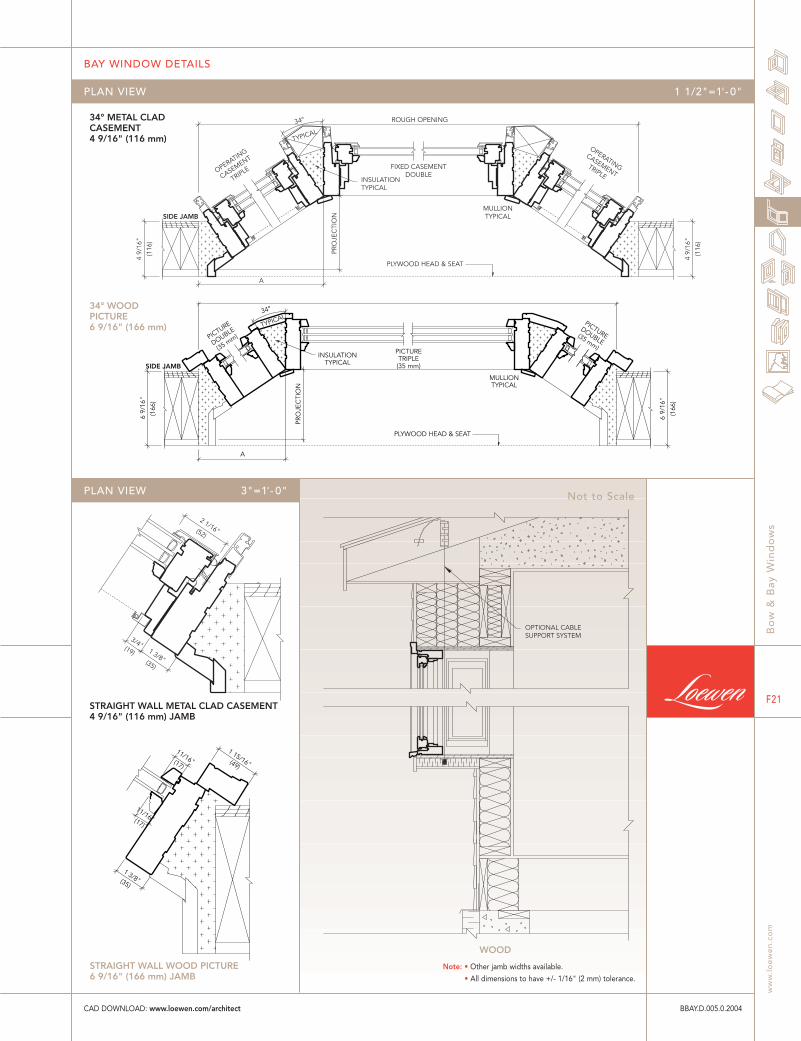
34° METAL CLAD CASEMENT 4 9/16" (116 mm)
STRAIGHT WALL METAL CLAD CASEMENT 4 9/16" (116 mm) JAMB
STRAIGHT WALL WOOD PICTURE 6 9/16" (166 mm) JAMB
34° WOOD PICTURE 6 9/16" (166 mm)
WOOD
OPTIONAL CABLE SUPPORT SYSTEM
(52)
(19) (35)
2 1/16"
3/4" 1 3/8"
OPERATING
CASEMENT TRIPLE
OPERATING
CASEMENT
TRIPLE FIXED CASEMENT
DOUBLE
PLYWOOD HEAD & SEAT
MULLION TYPICAL
INSULATION TYPICAL
SIDE JAMB
(116
)
4 9/
16"
A
PRO
JEC
TIO
N
ROUGH OPENING
(116
)
4 9/
16"
TYPICAL 34°
(49)(17)
(17)
(35)
1 15/16"
1 3/8"
11/16"
11/16"
PICTURETRIPLE(35 mm)
PICTUREDOUBLE
(35 mm)
PICTURE
DOUBLE
(35 mm)
INSULATIONTYPICAL
MULLIONTYPICAL
PLYWOOD HEAD & SEAT
(166
)
SIDE JAMB
(166
)
TYPICAL
6 9/
16"
A
PRO
JEC
TIO
N
6 9/
16"
34°
PLAN VIEW 3"=1'- 0"
BAY WINDOW DETAILS
Bo
w &
Bay
Win
do
ws
ww
w.l
oe
we
n.c
om
F21
BBAY.D.005.0.2004
PLAN VIEW 1 1/2"=1'- 0"
Not to Scale
CAD DOWNLOAD: www.loewen.com/architect
Note: • Other jamb widths available.
• All dimensions to have +/- 1/16" (2 mm) tolerance.
PLYWOOD HEAD & SEAT
TYPICAL
MULLION TYPICAL
SIDE JAMB
INSULATION TYPICAL
FIXED CASEMENT DOUBLE
OPERATIN
G
CASEM
ENT
TRIPL
E
OPERATING
CASEMENT
TRIPLE
(166
)
6 9/
16"
A
PRO
JEC
TIO
N
45°
6 9/
16"
(166
)
ROUGH OPENING
45° METAL CLAD CASEMENT 6 9/16" (166 mm)
45° WOOD PICTURE 4 9/16" (116 mm) JAMB
45° WOOD PICTURE 4 9/16" (116 mm) JAMB
(52)
(35)
(19)
2 1/1
6"
1 3/8
" 3/
4"
45° METAL CLAD CASEMENT 6 9/16" (166 mm) JAMB
(49)
(17)
(17)
(35)
11/16" 1 15/16"
1 3/8"
11/16"
PLYWOOD HEAD & SEAT
TYPICAL
MULLIONTYPICAL
SIDE JAMB
INSULATIONTYPICAL
PICTURETRIPLE(35 mm)
PICTU
RE
DOUBLE
(35 m
m)
PICTURE
DOUBLE(35 mm)
(116
)
(116
)
45°
4 9/
16"
A
ROUGH OPENING
PRO
JEC
TIO
N
4 9/
16"
Bo
w &
Bay
Win
do
ws
Can
ada
and
U.S
.A.
1.8
00
.56
3.9
36
7 /
In
tern
atio
nal
20
4.3
26
.64
46
F22
45° BAY WINDOW DETAILS
BBAY.D.006.0.2004
PLAN VIEW 1 1/2"=1'- 0"
PLAN VIEW 3"=1'- 0"
CAD DOWNLOAD: www.loewen.com/architect
Note: • Other jamb widths available.
• All dimensions to have +/- 1/16" (2 mm) tolerance.

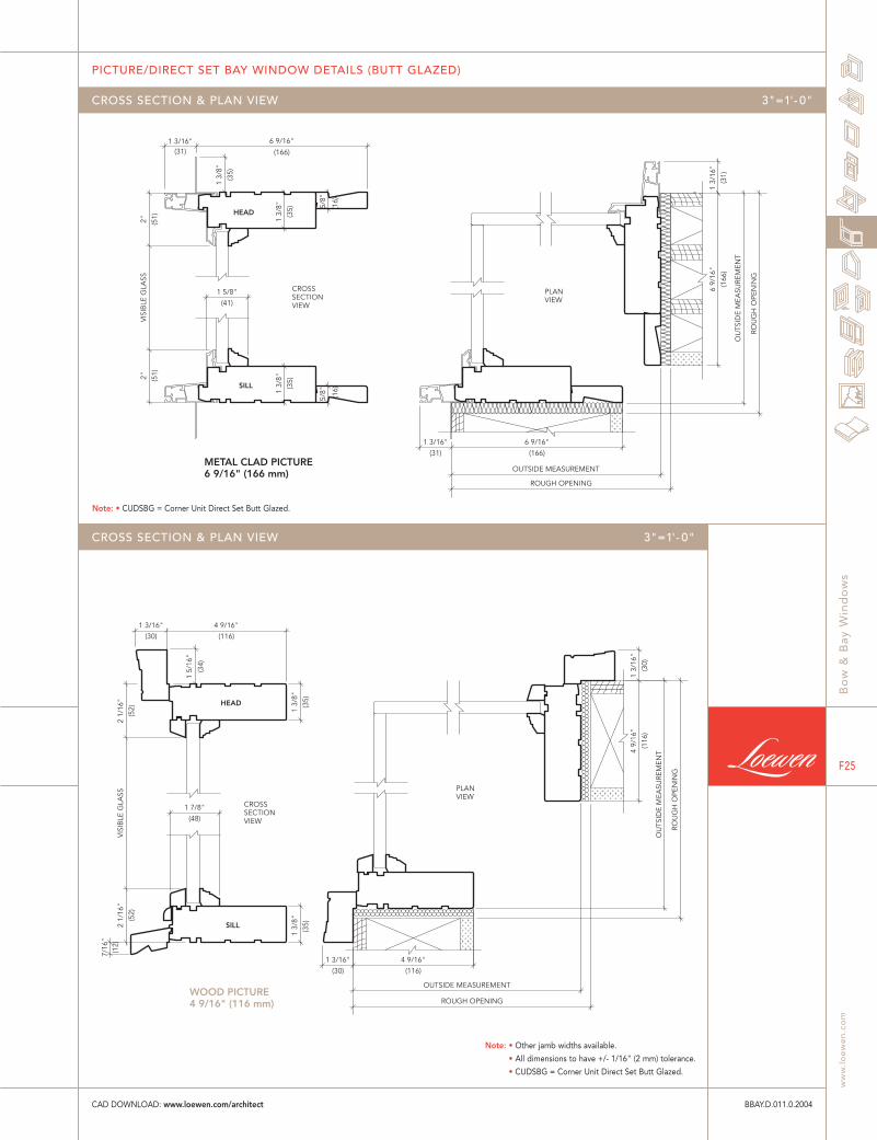
PICTURE/DIRECT SET BAY WINDOW DETAILS
Bo
w &
Bay
Win
do
ws
ww
w.l
oe
we
n.c
om
F23
BBAY.D.008.0.2004
CROSS SECTION & PLAN VIEW 3"=1'- 0"
CAD DOWNLOAD: www.loewen.com/architect
ROUGH OPENING
(116)
4 9/16"
OUTSIDE MEASUREMENT (30)
1 3/16"
OU
TSID
E M
EASU
REM
ENT
ROU
GH
OPE
NIN
G
(116
)
4 9/
16"
(30)
1 3/
16"
(12)
SILL
HEAD
(55)
2 3/16"
7/16
"
(35)
1 3/
8"
(116)
4 9/16"
(34)
1 5/
16"
(30)
1 3/16"
(35)
1 3/
8"
(52)
2 1/
16"
(52)
2 1/
16"
VIS
IBLE
GLA
SS
(8)
OUTSIDE MEASUREMENT (166)
6 9/16"
(31)
1 3/16" 5/
16"
ROU
GH
OPE
NIN
G
OU
TSID
E M
EASU
REM
ENT
(166
)
6 9/
16"
(31)
1 3/
16"
(16)
SILL
(16)
HEAD (35)
1 3/
8"
(47)
1 7/8" (3
5)
1 3/
8"
5/8"
(166)
6 9/16"
(31)
1 3/16"
(35)
1 3/
8"
5/8"
(51)
2"
(51)
2"
VIS
IBLE
GLA
SS
WOOD PICTURE 4 9/16" (116 mm)
METAL CLAD PICTURE 6 9/16" (166 mm)
CROSS SECTION VIEW
PLAN VIEW
CROSS SECTION VIEW
PLAN VIEW
ROUGH OPENING
Bo
w &
Bay
Win
do
ws
Can
ada
and
U.S
.A.
1.8
00
.56
3.9
36
7 /
In
tern
atio
nal
20
4.3
26
.64
46
F24
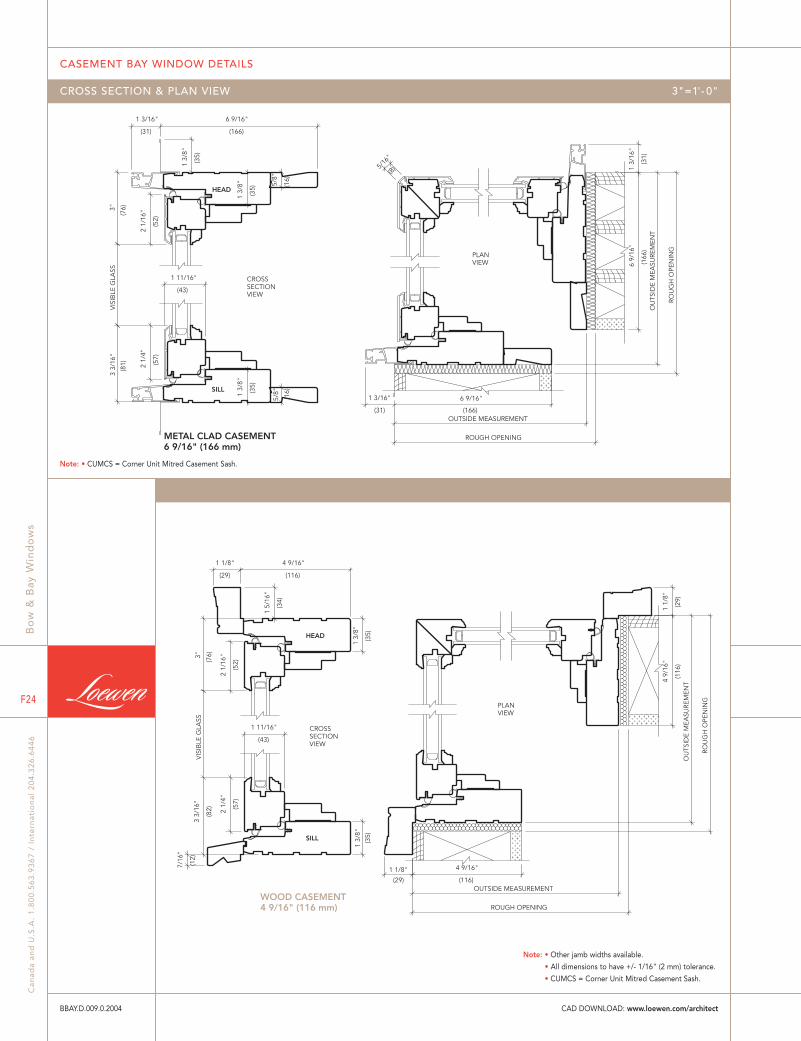
CASEMENT BAY WINDOW DETAILS
BBAY.D.009.0.2004
CROSS SECTION & PLAN VIEW 3"=1'- 0"
CAD DOWNLOAD: www.loewen.com/architect
(31) (166)
(166
)
(8)
(31)
6 9/
16"
OU
TSID
E M
EASU
REM
ENT
ROU
GH
OPE
NIN
G
5/16
"
6 9/16"
ROUGH OPENING
OUTSIDE MEASUREMENT
1 3/16"
1 3/
16"
(166)
HEAD
SILL
(57)
(81)
(43)
(31)(7
6)
(52)
(35)
(16)
(35)
(16)(3
5)
6 9/16"1 3/16"
1 11/16"
VIS
IBLE
GLA
SS3
3/16
"
2 1/
4"
3"
2 1/
16"
1 3/
8"
1 3/
8" 5/8"
1 3/
8"
5/8"
(116
)
(116)
(29)
ROU
GH
OPE
NIN
G
OU
TSID
E M
EASU
REM
ENT4
9/16
"
OUTSIDE MEASUREMENT
ROUGH OPENING
4 9/16"
(29)
1 1/8"
1 1/
8"
(12)
(82)
(43)
(57)
(76)
(52)
SILL
HEAD (35)
(34)
(29) (116)
1 5/
16"
4 9/16"
3"
1 11/16"
3 3/
16"
2 1/
4"
7/16
"
VIS
IBLE
GLA
SS
2 1/
16"
1 1/8"
1 3/
8"
(35)
1 3/
8"
WOOD CASEMENT4 9/16" (116 mm)
METAL CLAD CASEMENT6 9/16" (166 mm)
CROSSSECTIONVIEW
PLANVIEW
CROSSSECTIONVIEW
PLANVIEW
Note: • CUMCS = Corner Unit Mitred Casement Sash.
Note: • Other jamb widths available.
• All dimensions to have +/- 1/16" (2 mm) tolerance.
• CUMCS = Corner Unit Mitred Casement Sash.
(166)
6 9/16"
OUTSIDE MEASUREMENT
ROUGH OPENING
(31)
1 3/16"
(166
)
6 9/
16"
OU
TSID
E M
EASU
REM
ENT
ROU
GH
OPE
NIN
G
(31)
1 3/
16"
(16)SILL
HEAD
(16)
(41)
1 5/8"(3
5)
1 3/
8"
5/8"
(166)
6 9/16"
(35)
1 3/
8"
(31)1 3/16"
(35)
1 3/
8" 5/8"
(51)2"
(51)2"
VIS
IBLE
GLA
SS
OUTSIDE MEASUREMENT
(116)
4 9/16"
ROUGH OPENING
(30)
1 3/16"
ROU
GH
OPE
NIN
G
(30)
1 3/
16"
OU
TSID
E M
EASU
REM
ENT
(116
)
4 9/
16"
(12)
SILL
(35)
HEAD
(48)
1 7/8"
7/16
"
1 3/
8"
(116)
4 9/16"
(30)
1 3/16"
(34)
1 5/
16"
(35)
1 3/
8"
(52)
2 1/
16"
(52)
2 1/
16"
VIS
IBLE
GLA
SS
WOOD PICTURE4 9/16" (116 mm)
METAL CLAD PICTURE6 9/16" (166 mm)
CROSSSECTIONVIEW
PLANVIEW
CROSSSECTIONVIEW
PLANVIEW
CROSS SECTION & PLAN VIEW 3"=1'- 0"
PICTURE/DIRECT SET BAY WINDOW DETAILS (BUTT GLAZED)
Bo
w &
Bay
Win
do
ws
ww
w.l
oe
we
n.c
om
F25
BBAY.D.011.0.2004
CROSS SECTION & PLAN VIEW 3"=1'- 0"
CAD DOWNLOAD: www.loewen.com/architect
Note: • CUDSBG = Corner Unit Direct Set Butt Glazed.
Note: • Other jamb widths available.
• All dimensions to have +/- 1/16" (2 mm) tolerance.
• CUDSBG = Corner Unit Direct Set Butt Glazed.

METAL CLAD CASEMENT6 9/16" (166 mm)
SILL
HEAD
(35) (1
6)(1
6)
1 3/
8"
(166)
6 9/16"
(31)
1 3/16"
(43)
1 11/16"
VIS
IBLE
GLA
SS
(57)
2 1/
4"
(81)
3 3/
16"
(52)
2 1/
16"(76)3"
(35)
1 3/
8"
5/8"
(35)
1 3/
8"
5/8"
CROSSSECTIONVIEW
(31)
1 3/
16"
ROU
GH
OPE
NIN
G
OU
TSID
E M
EASU
REM
ENT
(166
)
6 9/
16"
OUTSIDE MEASUREMENT
ROUGH OPENING
(166)
6 9/16"
(31)
1 3/16"
PLANVIEW
WOOD CASEMENT4 9/16" (116 mm)
SILL
(12)
HEAD
(116)
4 9/16"
(76)3"
(82)
3 3/
16"
7/16
"
VIS
IBLE
GLA
SS
(43)
1 11/16"
(57)
2 1/
4"
(52)
2 1/
16"
(34)
1 5/
16"
(29)
1 1/8"
(35)
1 3/
8"(3
5)
1 3/
8"
CROSSSECTIONVIEW
(116
)
4 9/
16"
OU
TSID
E M
EASU
REM
ENT
ROU
GH
OPE
NIN
G
ROUGH OPENING
OUTSIDE MEASUREMENT
(116)
4 9/16"
(29)
1 1/8"
(29)
1 1/
8"
PLANVIEW
Bo
w &
Bay
Win
do
ws
Can
ada
and
U.S
.A.
1.8
00
.56
3.9
36
7 /
In
tern
atio
nal
20
4.3
26
.64
46
F26
CASEMENT BAY WINDOW DETAILS (BUTT GLAZED)
BBAY.D.012.0.2004
CROSS SECTION & PLAN VIEW 3"=1'- 0"
CROSS SECTION & PLAN VIEW 3"=1'- 0"
CAD DOWNLOAD: www.loewen.com/architect
Note: • CUSBG = Corner Unit Sashed Butt Glazed.
Note: • Other jamb widths available.
• All dimensions to have +/- 1/16" (2 mm) tolerance.
• CUSBG = Corner Unit Sashed Butt Glazed.