bosch paga system
DESCRIPTION
Bosch PAGA system.pdfTRANSCRIPT
www.boschsecurity.com
Praesideo - Digital Public Address and Emergency Sound System |
Praesideo - Digital PublicAddress and Emergency
Sound System
2 | Praesideo - Digital Public Address and Emergency Sound System
www.boschsecurity.com
Praesideo - Digital Public Address and Emergency Sound System
Praesideo is a fully digital public address system that meets all the requirements placed by professional users on a public address/emergency system. The system brings highly innovative and advanced digital technology to the public address market. The processing and communication of both audio signals and control data entirely in the digital domain makes the system superior to other currently available public address and emergency sound systems. Digital signal processing allows significant improvements in audio quality to be achieved. The Praesideo system is designed for configuration from a PC, which makes installation and setting of operating parameters very simple and user-friendly.
All audio processing is performed in the digital domain. Communication between the units is via plastic fiber or glass fiber cabling, depending on the distance between the units. The cabling uses the daisy chain principle. This makes the cabling and installation very quick, simple and easy. The system cabling is a closed loop, which allows redundancy to be achieved.
User-friendly Software Control
The system is supplied with user-friendly software for system configuration. This allows all system functions to be configured. The software is based on web technology, which gives authorized users full freedom of configuration in terms of time and location. The simplified and accurate organization of the programming features makes navigation highly user-friendly and fault-tolerant. The software also provides clear indication of any parameters, which have not been programmed before exiting from any stage of the configuration process.
Network Approach
The system architecture is based on daisy-chaining of the units. It is possible to add or remove equipment anywhere in the network without affecting the performance of other units, provided that the network connection is available. This makes the system easily expandable by the customer, without adding any additional electronics at the network controller unit. Thanks to this network architecture, users can start with a small system in the initial stage and expand the system later simply by adding the required new units to the existing network.
The system can be configured for redundant cabling using a ring cabling structure.
Distributed Control
The system is designed for distributed control of various system functions. The external interfaces, which are control inputs and outputs can be located anywhere in the network. The processing of audio input and output signals is located in each unit. This allows the network controller to concentrate on other activities like routing of announcement taking actions on control inputs, etc. As a result the response times are much shorter than for systems with centralized processing of all signals.
Combination of Functions
The Praesideo range of equipment has multiple functions combined in a single unit. This feature drastically reduces the number of different types of equipment used in the system. For example functions like audio processing, audio delay, amplifier monitoring including spare switching and speaker line monitoring are provided in the power amplifier unit itself. This makes the overall system highly cost-effective. The flexible architecture of the Praesideo range of equipment allows the customer to locate any type of equipment anywhere in the building. The configuration software enables the user to configure all the functional parameters. No programming is required at the equipment end, which drastically reduces the installation and commissioning time.
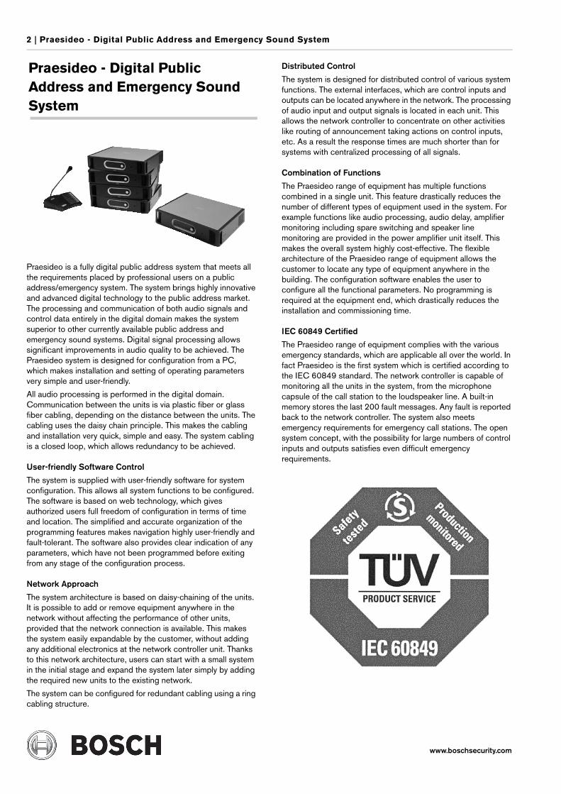
IEC 60849 Certified
The Praesideo range of equipment complies with the various emergency standards, which are applicable all over the world. In fact Praesideo is the first system which is certified according to the IEC 60849 standard. The network controller is capable of monitoring all the units in the system, from the microphone capsule of the call station to the loudspeaker line. A built-in memory stores the last 200 fault messages. Any fault is reported back to the network controller. The system also meets emergency requirements for emergency call stations. The open system concept, with the possibility for large numbers of control inputs and outputs satisfies even difficult emergency requirements.
Praesideo - Digital Public Address and Emergency Sound System | 3
www.boschsecurity.com
External Interfaces
The interfaces to the system can be audio, control input or Ethernet. The Ethernet open interface is provided at the network controller.
The audio and control inputs can be anywhere in the system, for example at the power amplifier, audio expander or network controller.
The system accepts even low-level signals via the control inputs. The configuration allows the user to configure the input to initiate the desired actions in the system. The flexibility to route any input from one system unit to another makes it possible to use the Praesideo range of products for a wide range of public address and emergency sound system applications.
Reduced Installation Costs
The Praesideo architecture uses the daisy chain principle for both data and audio signals. This makes the system wiring very cost-effective, using 2 fiber cores for data and audio communication and a copper wire pair to supply power to the units. Power supply for the system units can be provided locally if the distances are very long.
Combining various functions in a single unit also makes the equipment more cost-effective than systems in which separate units have to be purchased for all the specific functions. This combination of functions also saves lot of rack space and further reduces installation costs.
High System Flexibility
The Praesideo system is a highly versatile system which gives the user a high degree of flexibility in the number of zones, call stations, audio inputs and outputs, control inputs and outputs, etc.
System Overview
Network Controller
The network controller is the heart of the system, and stores all control information. It also provides the Ethernet interface for connection to the PC to enable system configuration as well as diagnostic and logging functions. The network controller also stores the digital audio messages for automatic announcements. The controller monitors all the system components and reports any changes in status. The unit provides 4 audio inputs and 4 audio outputs, as well as 8 control inputs and 5 control outputs.
The control inputs can be used to trigger actions in the system. In the configuration software, the user can define the types of inputs. They can be programmed for momentary or toggle operation. Of course these functions are also available for other control inputs in the system. The control outputs can be used to initiate external actions, and can be linked to any of the input triggers.
The network controller stores the configuration details and the last 200 fault messages. The availability of the digital audio messages, the alarm tones and alarm tone generator and the control inputs are continuously monitored. To monitor the audio outputs an internally generated pilot tone can be provided to the audio outputs.
Audio Expander
The audio expander is used if the system requires additional audio inputs and outputs. The unit provides 4 transformer isolated audio inputs and 4 transformer isolated audio outputs, as well as 8 control inputs and 5 control outputs. The audio inputs can be configured for background music, microphone or line inputs. As for the network controller, the control inputs can be configured to initiate external actions.
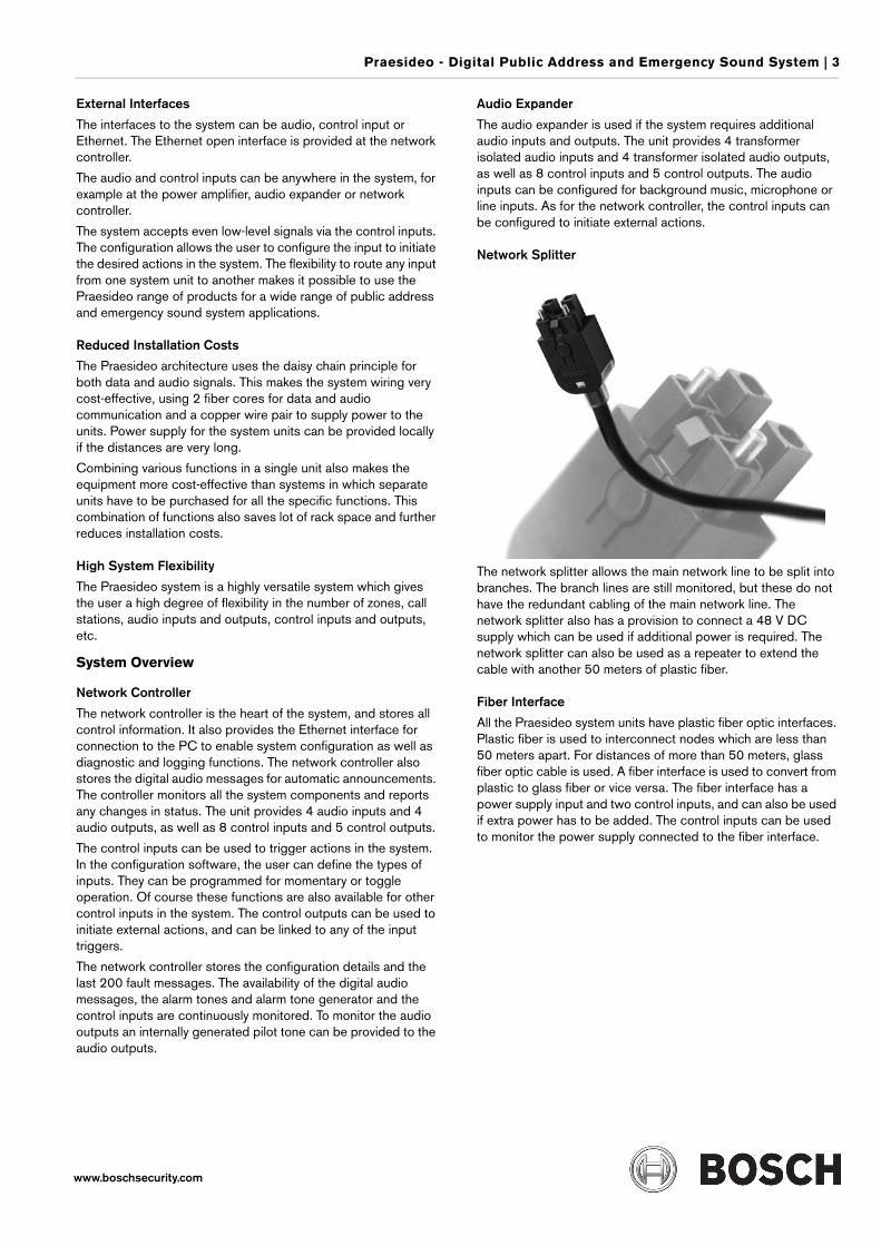
Network Splitter
The network splitter allows the main network line to be split into branches. The branch lines are still monitored, but these do not have the redundant cabling of the main network line. The network splitter also has a provision to connect a 48 V DC supply which can be used if additional power is required. The network splitter can also be used as a repeater to extend the cable with another 50 meters of plastic fiber.
Fiber Interface
All the Praesideo system units have plastic fiber optic interfaces. Plastic fiber is used to interconnect nodes which are less than 50 meters apart. For distances of more than 50 meters, glass fiber optic cable is used. A fiber interface is used to convert from plastic to glass fiber or vice versa. The fiber interface has a power supply input and two control inputs, and can also be used if extra power has to be added. The control inputs can be used to monitor the power supply connected to the fiber interface.
4 | Praesideo - Digital Public Address and Emergency Sound System
www.boschsecurity.com
Power Amplifier
There are four types of power amplifier units in the Praesideo product range. These differ in the number of amplifier channels per frame and the power ratings of the individual amplifier channels. The types of power amplifiers are as follows:
The power amplifiers can be selected for 100 V, 70 V and 50 V output tapping. Audio input is provided via the fiber optic network cable.
The power amplifiers are equipped with amplifier monitoring and change-over relays. The amplifier provides short-to-ground and short-circuit detection functions. If an end-of-line supervision card is plugged in, the loudspeaker lines are also monitored for open circuits. The pilot tone for the monitoring is generated in the power amplifier itself.
The power amplifiers are equipped with audio processing facilities for each amplifier channel. It is possible to have 3 parametric equalizer sections and 2 shelving equalizers. The power amplifiers can be connected to the network line directly. Ambient microphone connection enables output level adjustment for maximum intelligibility.
The power amplifier has a provision for connecting a 48 V DC backup power supply. The 48 V is protected against reverse polarity, and availability of the 48 V supply is continuously monitored.
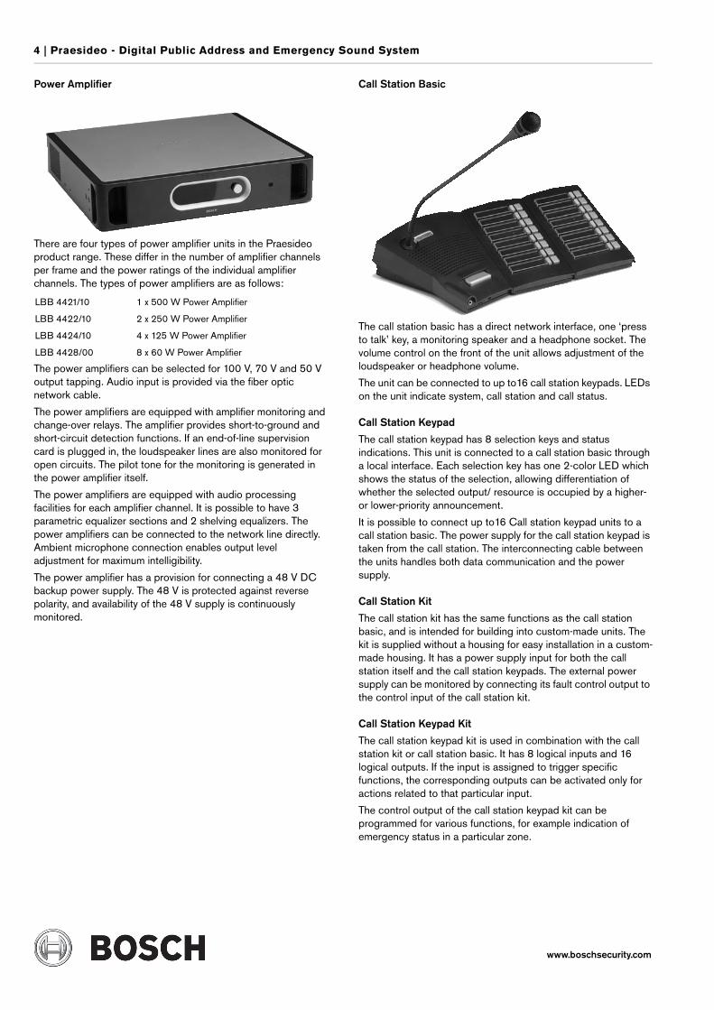
Call Station Basic
The call station basic has a direct network interface, one ‘press to talk’ key, a monitoring speaker and a headphone socket. The volume control on the front of the unit allows adjustment of the loudspeaker or headphone volume.
The unit can be connected to up to16 call station keypads. LEDs on the unit indicate system, call station and call status.
Call Station Keypad
The call station keypad has 8 selection keys and status indications. This unit is connected to a call station basic through a local interface. Each selection key has one 2-color LED which shows the status of the selection, allowing differentiation of whether the selected output/ resource is occupied by a higher- or lower-priority announcement.
It is possible to connect up to16 Call station keypad units to a call station basic. The power supply for the call station keypad is taken from the call station. The interconnecting cable between the units handles both data communication and the power supply.
Call Station Kit
The call station kit has the same functions as the call station basic, and is intended for building into custom-made units. The kit is supplied without a housing for easy installation in a custom-made housing. It has a power supply input for both the call station itself and the call station keypads. The external power supply can be monitored by connecting its fault control output to the control input of the call station kit.
Call Station Keypad Kit
The call station keypad kit is used in combination with the call station kit or call station basic. It has 8 logical inputs and 16 logical outputs. If the input is assigned to trigger specific functions, the corresponding outputs can be activated only for actions related to that particular input.
The control output of the call station keypad kit can be programmed for various functions, for example indication of emergency status in a particular zone.
LBB 4421/10 1 x 500 W Power Amplifier
LBB 4422/10 2 x 250 W Power Amplifier
LBB 4424/10 4 x 125 W Power Amplifier
LBB 4428/00 8 x 60 W Power Amplifier
Praesideo - Digital Public Address and Emergency Sound System | 5
www.boschsecurity.com
LBB 4401/00 Network Controller
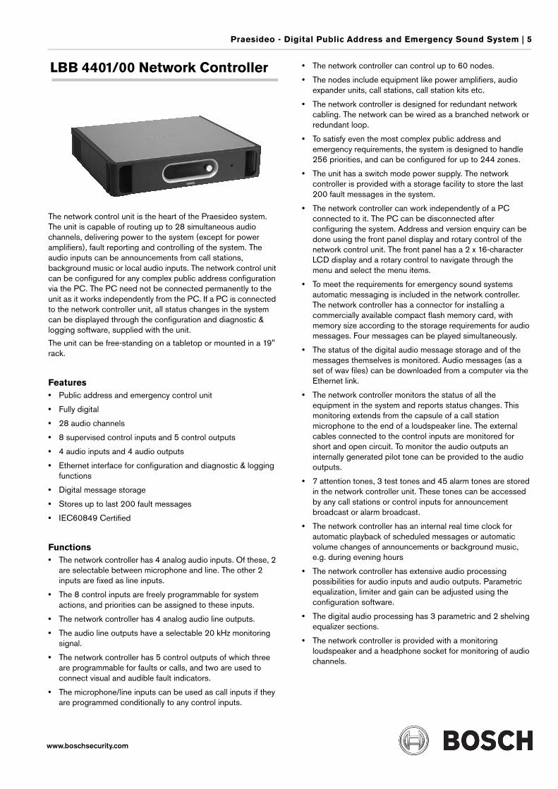
The network control unit is the heart of the Praesideo system. The unit is capable of routing up to 28 simultaneous audio channels, delivering power to the system (except for power amplifiers), fault reporting and controlling of the system. The audio inputs can be announcements from call stations, background music or local audio inputs. The network control unit can be configured for any complex public address configuration via the PC. The PC need not be connected permanently to the unit as it works independently from the PC. If a PC is connected to the network controller unit, all status changes in the system can be displayed through the configuration and diagnostic & logging software, supplied with the unit.
The unit can be free-standing on a tabletop or mounted in a 19" rack.
Features• Public address and emergency control unit
• Fully digital
• 28 audio channels
• 8 supervised control inputs and 5 control outputs
• 4 audio inputs and 4 audio outputs
• Ethernet interface for configuration and diagnostic & logging functions
• Digital message storage
• Stores up to last 200 fault messages
• IEC60849 Certified
Functions• The network controller has 4 analog audio inputs. Of these, 2
are selectable between microphone and line. The other 2 inputs are fixed as line inputs.
• The 8 control inputs are freely programmable for system actions, and priorities can be assigned to these inputs.
• The network controller has 4 analog audio line outputs.
• The audio line outputs have a selectable 20 kHz monitoring signal.
• The network controller has 5 control outputs of which three are programmable for faults or calls, and two are used to connect visual and audible fault indicators.
• The microphone/line inputs can be used as call inputs if they are programmed conditionally to any control inputs.
• The network controller can control up to 60 nodes.
• The nodes include equipment like power amplifiers, audio expander units, call stations, call station kits etc.
• The network controller is designed for redundant network cabling. The network can be wired as a branched network or redundant loop.
• To satisfy even the most complex public address and emergency requirements, the system is designed to handle 256 priorities, and can be configured for up to 244 zones.
• The unit has a switch mode power supply. The network controller is provided with a storage facility to store the last 200 fault messages in the system.
• The network controller can work independently of a PC connected to it. The PC can be disconnected after configuring the system. Address and version enquiry can be done using the front panel display and rotary control of the network control unit. The front panel has a 2 x 16-character LCD display and a rotary control to navigate through the menu and select the menu items.
• To meet the requirements for emergency sound systems automatic messaging is included in the network controller. The network controller has a connector for installing a commercially available compact flash memory card, with memory size according to the storage requirements for audio messages. Four messages can be played simultaneously.
• The status of the digital audio message storage and of the messages themselves is monitored. Audio messages (as a set of wav files) can be downloaded from a computer via the Ethernet link.
• The network controller monitors the status of all the equipment in the system and reports status changes. This monitoring extends from the capsule of a call station microphone to the end of a loudspeaker line. The external cables connected to the control inputs are monitored for short and open circuit. To monitor the audio outputs an internally generated pilot tone can be provided to the audio outputs.
• 7 attention tones, 3 test tones and 45 alarm tones are stored in the network controller unit. These tones can be accessed by any call stations or control inputs for announcement broadcast or alarm broadcast.
• The network controller has an internal real time clock for automatic playback of scheduled messages or automatic volume changes of announcements or background music, e.g. during evening hours
• The network controller has extensive audio processing possibilities for audio inputs and audio outputs. Parametric equalization, limiter and gain can be adjusted using the configuration software.
• The digital audio processing has 3 parametric and 2 shelving equalizer sections.
• The network controller is provided with a monitoring loudspeaker and a headphone socket for monitoring of audio channels.
6 | Praesideo - Digital Public Address and Emergency Sound System
www.boschsecurity.com
Certifications and Approvals
Installation/Configuration Notes
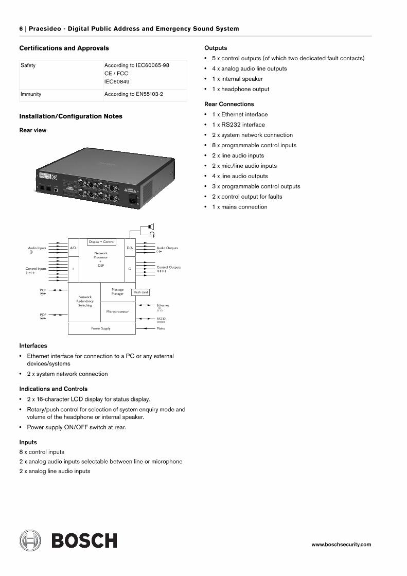
Rear view
Interfaces
• Ethernet interface for connection to a PC or any external devices/systems
• 2 x system network connection
Indications and Controls
• 2 x 16-character LCD display for status display.
• Rotary/push control for selection of system enquiry mode and volume of the headphone or internal speaker.
• Power supply ON/OFF switch at rear.
Inputs
8 x control inputs
2 x analog audio inputs selectable between line or microphone
2 x analog line audio inputs
Outputs
• 5 x control outputs (of which two dedicated fault contacts)
• 4 x analog audio line outputs
• 1 x internal speaker
• 1 x headphone output
Rear Connections
• 1 x Ethernet interface
• 1 x RS232 interface
• 2 x system network connection
• 8 x programmable control inputs
• 2 x line audio inputs
• 2 x mic./line audio inputs
• 4 x line audio outputs
• 3 x programmable control outputs
• 2 x control output for faults
• 1 x mains connection
Safety According to IEC60065-98
CE / FCC
IEC60849
Immunity According to EN55103-2
Praesideo - Digital Public Address and Emergency Sound System | 7
www.boschsecurity.com
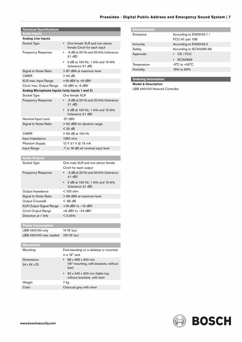
Technical SpecificationsAudio Inputs
Analog Line InputsSocket Type • One female XLR and one stereo
female Cinch for each input
Frequency Response • -3 dB at 20 Hz and 20 kHz (tolerance ±1 dB)
• 0 dB at 100 Hz, 1 kHz and 10 kHz (tolerance ±1 dB)
Signal to Noise Ratio > 87 dBA at maximum level
CMRR > 40 dB
XLR max. Input Range +18 dBV to +6 dBV
Cinch max. Output Range +6 dBV to -6 dBV
Analog Microphone Inputs (only inputs 1 and 2)Socket Type One female XLR
Frequency Response • -3 dB at 20 Hz and 20 kHz (tolerance ±1 dB)
• 0 dB at 100 Hz, 1 kHz and 10 kHz (tolerance ±1 dB)
Nominal Input Level -57 dBV
Signal to Noise Ratio > 62 dBA for dynamic range
< 25 dB
CMRR > 55 dB at 100 Hz
Input Impedance 1360 ohm
Phantom Supply 12 V ±1 V @ 15 mA
Input Range -7 to 18 dB ref nominal input level
Audio Outputs
Socket Type One male XLR and one stereo female
Cinch for each output
Frequency Response • -3 dB at 20 Hz and 20 kHz (tolerance ±1 dB)
• 0 dB at 100 Hz, 1 kHz and 10 kHz (tolerance ±1 dB)
Output Impedance < 100 ohm
Signal to Noise Ratio > 89 dBA at maximum level
Output Crosstalk < -85 dB
XLR Output Signal Range +18 dBV to –12 dBV
Cinch Output Range +6 dBV to –24 dBV
Distortion at 1 kHz < 0.05%
Power Consumption
LBB 4401/00 only 14 W (ac)
LBB 4401/00 max. loaded 150 W (ac)
Mechanical
Mounting Free-standing on a tabletop or mounted
in a 19" rack
Dimensions
(H x W x D)
• 88 x 483 x 400 mm (19”-mounting, with brackets, without feet)
• 92 x 440 x 400 mm (table top, without brackets, with feet)
Weight 7 kg
Color Charcoal grey with silver
Environmental
Emissions According to EN55103-1 /
FCC-47 part 15B
Immunity According to EN55103-2
Safety According to IEC60065-98
Approvals • CE / FCC
• IEC60849
Temperature -5°C to +55°C
Humidity 15% to 90%
Ordering Information
Model & DescriptionLBB 4401/00 Network Controller
8 | Praesideo - Digital Public Address and Emergency Sound System
www.boschsecurity.com
LBB 4402/00 Audio Expander
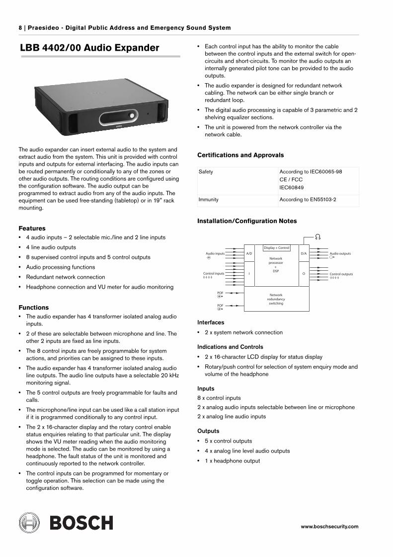
The audio expander can insert external audio to the system and extract audio from the system. This unit is provided with control inputs and outputs for external interfacing. The audio inputs can be routed permanently or conditionally to any of the zones or other audio outputs. The routing conditions are configured using the configuration software. The audio output can be programmed to extract audio from any of the audio inputs. The equipment can be used free-standing (tabletop) or in 19" rack mounting.
Features• 4 audio inputs – 2 selectable mic./line and 2 line inputs
• 4 line audio outputs
• 8 supervised control inputs and 5 control outputs
• Audio processing functions
• Redundant network connection
• Headphone connection and VU meter for audio monitoring
Functions• The audio expander has 4 transformer isolated analog audio
inputs.
• 2 of these are selectable between microphone and line. The other 2 inputs are fixed as line inputs.
• The 8 control inputs are freely programmable for system actions, and priorities can be assigned to these inputs.
• The audio expander has 4 transformer isolated analog audio line outputs. The audio line outputs have a selectable 20 kHz monitoring signal.
• The 5 control outputs are freely programmable for faults and calls.
• The microphone/line input can be used like a call station input if it is programmed conditionally to any control input.
• The 2 x 16-character display and the rotary control enable status enquiries relating to that particular unit. The display shows the VU meter reading when the audio monitoring mode is selected. The audio can be monitored by using a headphone. The fault status of the unit is monitored and continuously reported to the network controller.
• The control inputs can be programmed for momentary or toggle operation. This selection can be made using the configuration software.
• Each control input has the ability to monitor the cable between the control inputs and the external switch for open-circuits and short-circuits. To monitor the audio outputs an internally generated pilot tone can be provided to the audio outputs.
• The audio expander is designed for redundant network cabling. The network can be either single branch or redundant loop.
• The digital audio processing is capable of 3 parametric and 2 shelving equalizer sections.
• The unit is powered from the network controller via the network cable.
Certifications and Approvals
Installation/Configuration Notes
Interfaces
• 2 x system network connection
Indications and Controls
• 2 x 16-character LCD display for status display
• Rotary/push control for selection of system enquiry mode and volume of the headphone
Inputs
8 x control inputs
2 x analog audio inputs selectable between line or microphone
2 x analog line audio inputs
Outputs
• 5 x control outputs
• 4 x analog line level audio outputs
• 1 x headphone output
Safety According to IEC60065-98
CE / FCC
IEC60849
Immunity According to EN55103-2
A/D D/A
Networkprocessor
+ DSP
Display + Control
Audio outputsAudio inputs
Control inputs
POF
POF
Control outputs
Networkredundancy
switching
I O
Praesideo - Digital Public Address and Emergency Sound System | 9
www.boschsecurity.com
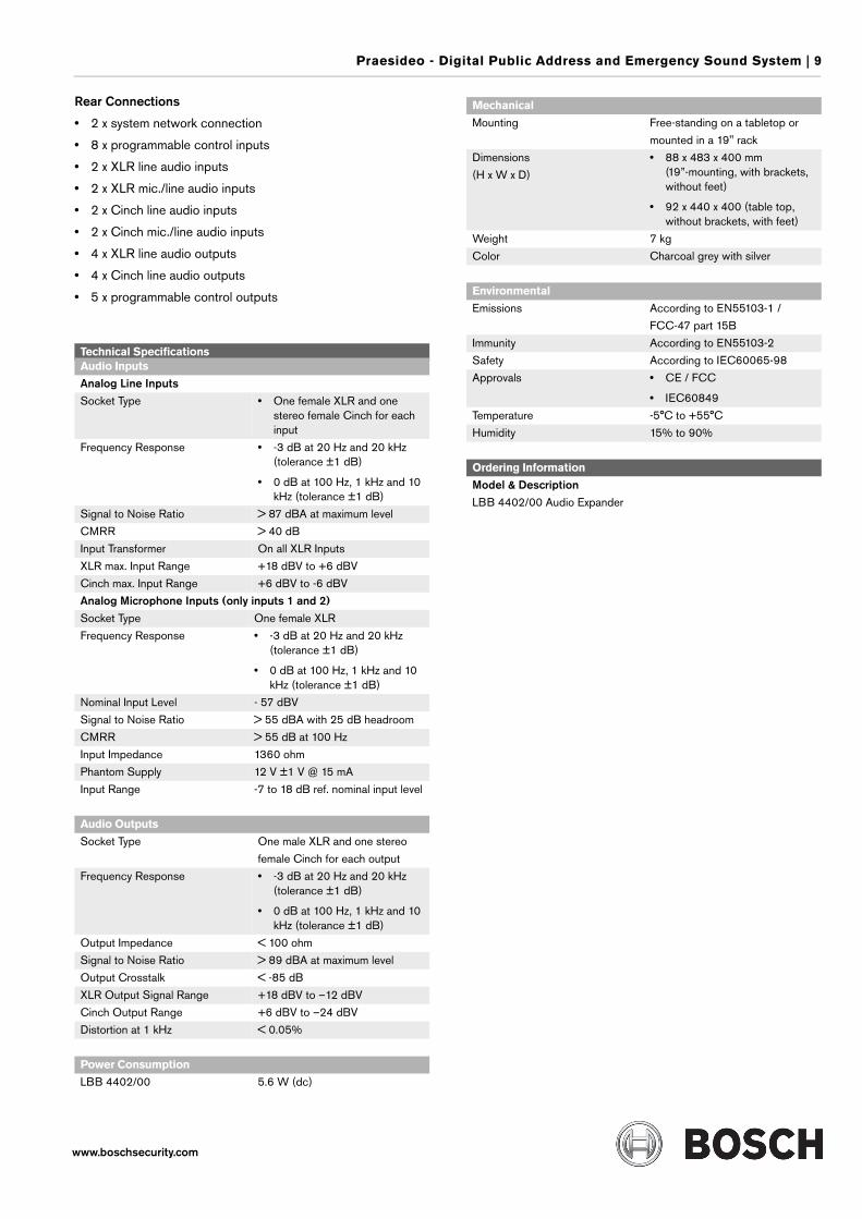
Rear Connections
• 2 x system network connection
• 8 x programmable control inputs
• 2 x XLR line audio inputs
• 2 x XLR mic./line audio inputs
• 2 x Cinch line audio inputs
• 2 x Cinch mic./line audio inputs
• 4 x XLR line audio outputs
• 4 x Cinch line audio outputs
• 5 x programmable control outputs
Technical SpecificationsAudio Inputs
Analog Line InputsSocket Type • One female XLR and one
stereo female Cinch for each input
Frequency Response • -3 dB at 20 Hz and 20 kHz (tolerance ±1 dB)
• 0 dB at 100 Hz, 1 kHz and 10 kHz (tolerance ±1 dB)
Signal to Noise Ratio > 87 dBA at maximum level
CMRR > 40 dB
Input Transformer On all XLR Inputs
XLR max. Input Range +18 dBV to +6 dBV
Cinch max. Input Range +6 dBV to -6 dBV
Analog Microphone Inputs (only inputs 1 and 2)Socket Type One female XLR
Frequency Response • -3 dB at 20 Hz and 20 kHz (tolerance ±1 dB)
• 0 dB at 100 Hz, 1 kHz and 10 kHz (tolerance ±1 dB)
Nominal Input Level - 57 dBV
Signal to Noise Ratio > 55 dBA with 25 dB headroom
CMRR > 55 dB at 100 Hz
Input Impedance 1360 ohm
Phantom Supply 12 V ±1 V @ 15 mA
Input Range -7 to 18 dB ref. nominal input level
Audio Outputs
Socket Type One male XLR and one stereo
female Cinch for each output
Frequency Response • -3 dB at 20 Hz and 20 kHz (tolerance ±1 dB)
• 0 dB at 100 Hz, 1 kHz and 10 kHz (tolerance ±1 dB)
Output Impedance < 100 ohm
Signal to Noise Ratio > 89 dBA at maximum level
Output Crosstalk < -85 dB
XLR Output Signal Range +18 dBV to –12 dBV
Cinch Output Range +6 dBV to –24 dBV
Distortion at 1 kHz < 0.05%
Power Consumption
LBB 4402/00 5.6 W (dc)
Mechanical
Mounting Free-standing on a tabletop or
mounted in a 19" rack
Dimensions
(H x W x D)
• 88 x 483 x 400 mm (19”-mounting, with brackets, without feet)
• 92 x 440 x 400 (table top, without brackets, with feet)
Weight 7 kg
Color Charcoal grey with silver
Environmental
Emissions According to EN55103-1 /
FCC-47 part 15B
Immunity According to EN55103-2
Safety According to IEC60065-98
Approvals • CE / FCC
• IEC60849
Temperature -5°C to +55°C
Humidity 15% to 90%
Ordering Information
Model & DescriptionLBB 4402/00 Audio Expander
10 | Praesideo - Digital Public Address and Emergency Sound System
www.boschsecurity.com
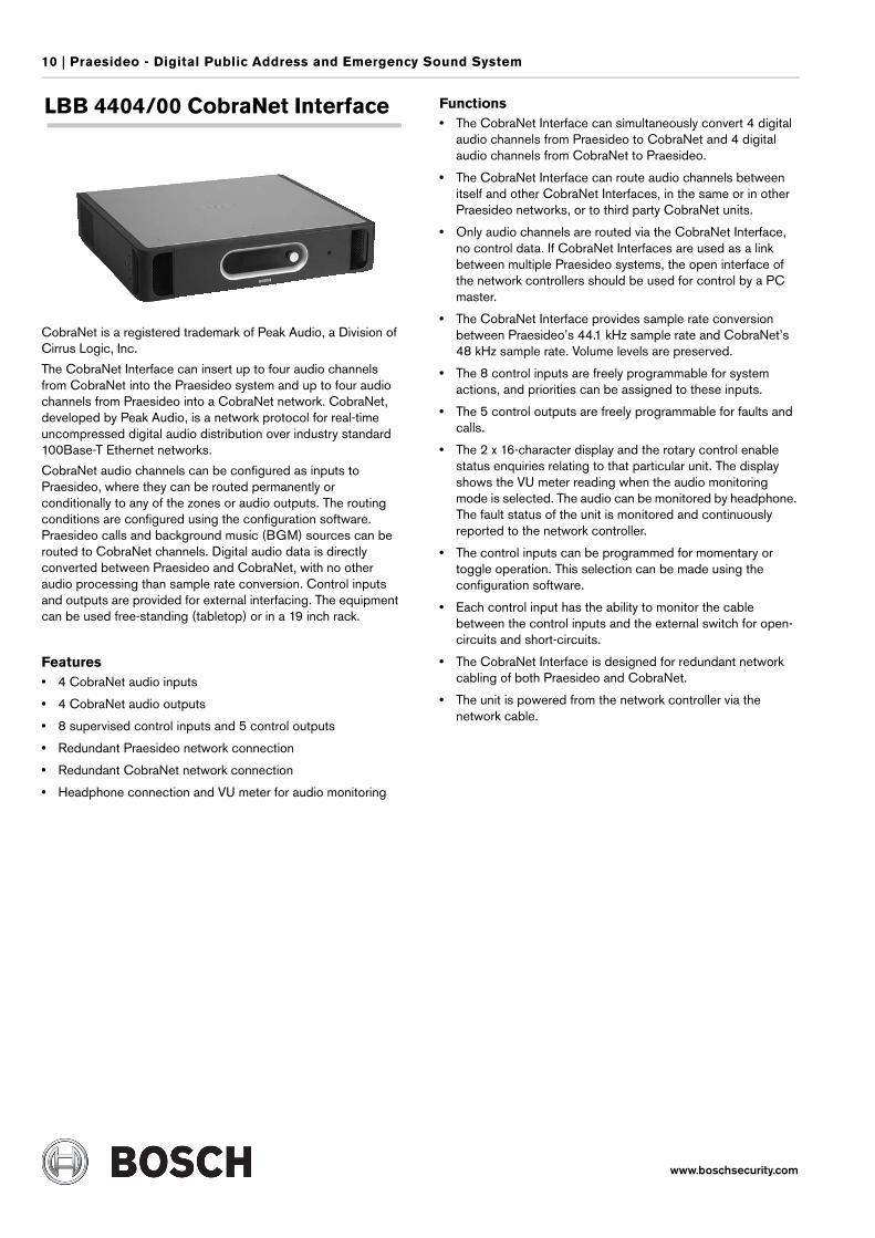
LBB 4404/00 CobraNet Interface
CobraNet is a registered trademark of Peak Audio, a Division of Cirrus Logic, Inc.
The CobraNet Interface can insert up to four audio channels from CobraNet into the Praesideo system and up to four audio channels from Praesideo into a CobraNet network. CobraNet, developed by Peak Audio, is a network protocol for real-time uncompressed digital audio distribution over industry standard 100Base-T Ethernet networks.
CobraNet audio channels can be configured as inputs to Praesideo, where they can be routed permanently or conditionally to any of the zones or audio outputs. The routing conditions are configured using the configuration software. Praesideo calls and background music (BGM) sources can be routed to CobraNet channels. Digital audio data is directly converted between Praesideo and CobraNet, with no other audio processing than sample rate conversion. Control inputs and outputs are provided for external interfacing. The equipment can be used free-standing (tabletop) or in a 19 inch rack.
Features• 4 CobraNet audio inputs
• 4 CobraNet audio outputs
• 8 supervised control inputs and 5 control outputs
• Redundant Praesideo network connection
• Redundant CobraNet network connection
• Headphone connection and VU meter for audio monitoring
Functions• The CobraNet Interface can simultaneously convert 4 digital
audio channels from Praesideo to CobraNet and 4 digital audio channels from CobraNet to Praesideo.
• The CobraNet Interface can route audio channels between itself and other CobraNet Interfaces, in the same or in other Praesideo networks, or to third party CobraNet units.
• Only audio channels are routed via the CobraNet Interface, no control data. If CobraNet Interfaces are used as a link between multiple Praesideo systems, the open interface of the network controllers should be used for control by a PC master.
• The CobraNet Interface provides sample rate conversion between Praesideo’s 44.1 kHz sample rate and CobraNet’s 48 kHz sample rate. Volume levels are preserved.
• The 8 control inputs are freely programmable for system actions, and priorities can be assigned to these inputs.
• The 5 control outputs are freely programmable for faults and calls.
• The 2 x 16-character display and the rotary control enable status enquiries relating to that particular unit. The display shows the VU meter reading when the audio monitoring mode is selected. The audio can be monitored by headphone. The fault status of the unit is monitored and continuously reported to the network controller.
• The control inputs can be programmed for momentary or toggle operation. This selection can be made using the configuration software.
• Each control input has the ability to monitor the cable between the control inputs and the external switch for open-circuits and short-circuits.
• The CobraNet Interface is designed for redundant network cabling of both Praesideo and CobraNet.
• The unit is powered from the network controller via the network cable.
Praesideo - Digital Public Address and Emergency Sound System | 11
www.boschsecurity.com
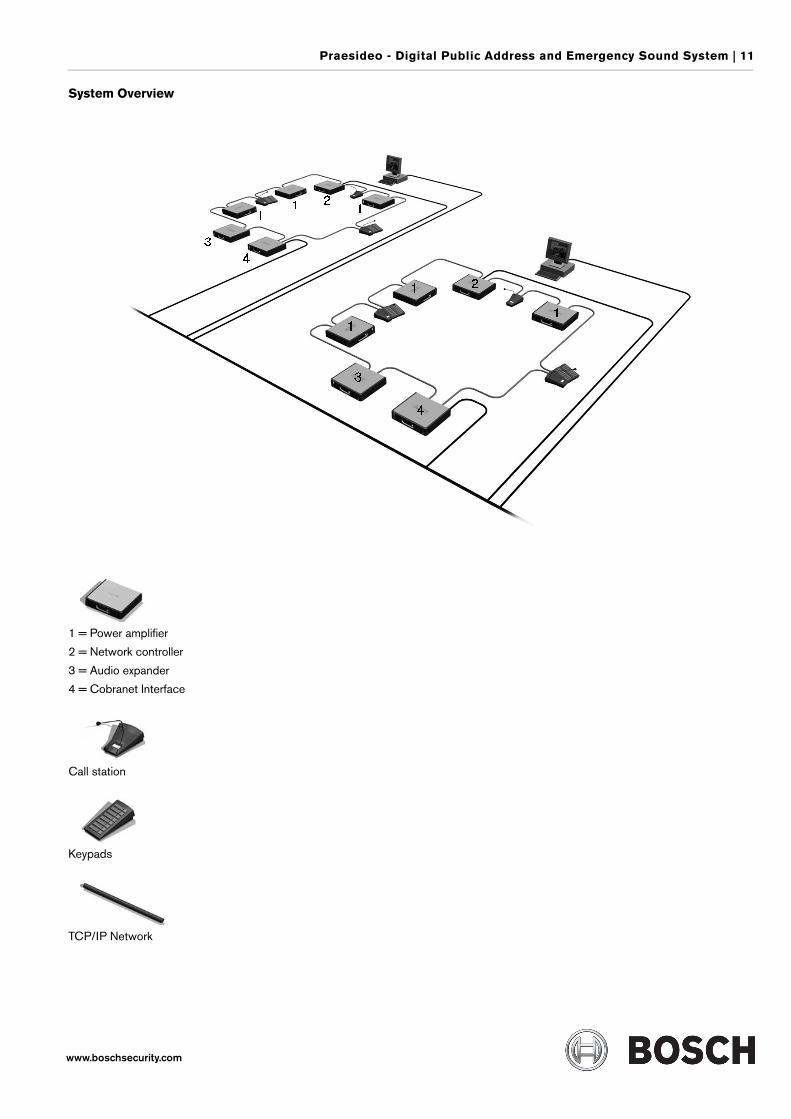
System Overview
1 = Power amplifier
2 = Network controller
3 = Audio expander
4 = Cobranet Interface
Call station
Keypads
TCP/IP Network
12 | Praesideo - Digital Public Address and Emergency Sound System
www.boschsecurity.com
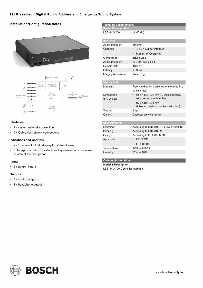
Installation/Configuration Notes
Interfaces
• 2 x system network connection
• 2 x CobraNet network connections
Indications and Controls
• 2 x 16 character LCD display for status display
• Rotary/push control for selection of system enquiry mode and volume of the headphone
Inputs
• 8 x control inputs
Outputs
• 5 x control outputs
• 1 x headphone output
C obraNetInterface
S ample rateconversion D/A
Networkprocessor
+DS P
C AT5
C AT5
C ontrol inputs
P O F
P O F
C ontrol outputs
Networkredundancy
switching
I O
Display + C ontrol
Technical SpecificationsPower Consumption
LBB 4404/00 11 W (dc)
Electrical
Audio Transport Ethernet
Channels • 4 in / 4 out per interface
• Max 64 on CobraNet
Compliance IEEE 802.3
Audio Transport: 16-, 20-, and 24-bit
Sample Rate 48 kHz
Latency 5.33 ms
Integrity Assurance Watchdog
Mechanical
Mounting Free-standing on a tabletop or mounted in a
19 inch rack
Dimensions
(H x W x D)
• 88 x 483 x 400 mm (19 inch mounting, with brackets, without feet)
• 92 x 440 x 400 mm (table top, without brackets, with feet)
Weight 7 kg
Color Charcoal grey with silver
Environmental
Emissions According to EN55103-1 / FCC-47 part 15
Immunity According to EN55103-2
Safety According to IEC60065-98
Approvals • CE / FCC
• IEC60849
Temperature -5°C to +55°C
Humidity 15% to 90%
Ordering Information
Model & DescriptionLBB 4404/00 CobraNet Interface
Praesideo - Digital Public Address and Emergency Sound System | 13
www.boschsecurity.com
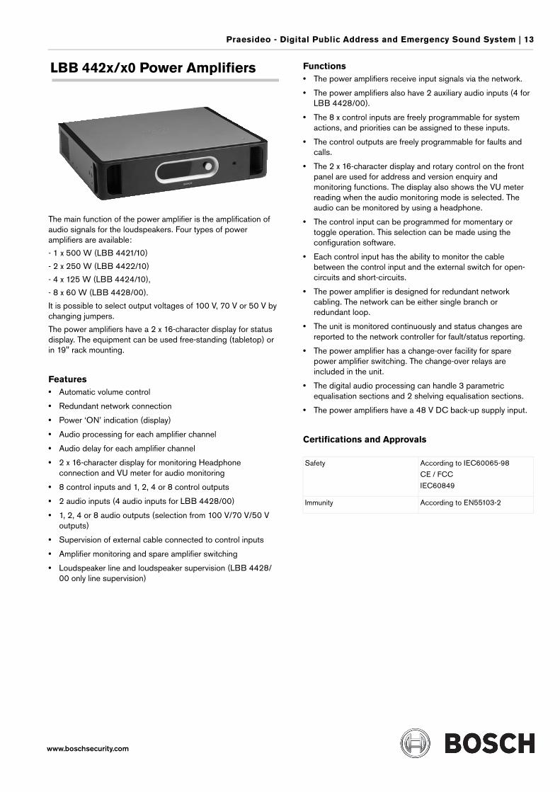
LBB 442x/x0 Power Amplifiers
The main function of the power amplifier is the amplification of audio signals for the loudspeakers. Four types of power amplifiers are available:
- 1 x 500 W (LBB 4421/10)
- 2 x 250 W (LBB 4422/10)
- 4 x 125 W (LBB 4424/10),
- 8 x 60 W (LBB 4428/00).
It is possible to select output voltages of 100 V, 70 V or 50 V by changing jumpers.
The power amplifiers have a 2 x 16-character display for status display. The equipment can be used free-standing (tabletop) or in 19" rack mounting.
Features• Automatic volume control
• Redundant network connection
• Power ‘ON’ indication (display)
• Audio processing for each amplifier channel
• Audio delay for each amplifier channel
• 2 x 16-character display for monitoring Headphone connection and VU meter for audio monitoring
• 8 control inputs and 1, 2, 4 or 8 control outputs
• 2 audio inputs (4 audio inputs for LBB 4428/00)
• 1, 2, 4 or 8 audio outputs (selection from 100 V/70 V/50 V outputs)
• Supervision of external cable connected to control inputs
• Amplifier monitoring and spare amplifier switching
• Loudspeaker line and loudspeaker supervision (LBB 4428/00 only line supervision)
Functions• The power amplifiers receive input signals via the network.
• The power amplifiers also have 2 auxiliary audio inputs (4 for LBB 4428/00).
• The 8 x control inputs are freely programmable for system actions, and priorities can be assigned to these inputs.
• The control outputs are freely programmable for faults and calls.
• The 2 x 16-character display and rotary control on the front panel are used for address and version enquiry and monitoring functions. The display also shows the VU meter reading when the audio monitoring mode is selected. The audio can be monitored by using a headphone.
• The control input can be programmed for momentary or toggle operation. This selection can be made using the configuration software.
• Each control input has the ability to monitor the cable between the control input and the external switch for open-circuits and short-circuits.
• The power amplifier is designed for redundant network cabling. The network can be either single branch or redundant loop.
• The unit is monitored continuously and status changes are reported to the network controller for fault/status reporting.
• The power amplifier has a change-over facility for spare power amplifier switching. The change-over relays are included in the unit.
• The digital audio processing can handle 3 parametric equalisation sections and 2 shelving equalisation sections.
• The power amplifiers have a 48 V DC back-up supply input.
Certifications and Approvals
Safety According to IEC60065-98
CE / FCC
IEC60849
Immunity According to EN55103-2
14 | Praesideo - Digital Public Address and Emergency Sound System
www.boschsecurity.com
Installation/Configuration Notes
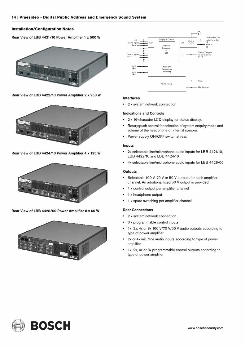
Rear View of LBB 4421/10 Power Amplifier 1 x 500 W
Rear View of LBB 4422/10 Power Amplifier 2 x 250 W
Rear View of LBB 4424/10 Power Amplifier 4 x 125 W
Rear View of LBB 4428/00 Power Amplifier 8 x 60 W
Interfaces
• 2 x system network connection
Indications and Controls
• 2 x 16-character LCD display for status display.
• Rotary/push control for selection of system enquiry mode and volume of the headphone or internal speaker.
• Power supply ON/OFF switch at rear.
Inputs
• 2x selectable line/microphone audio inputs for LBB 4421/10, LBB 4422/10 and LBB 4424/10
• 4x selectable line/microphone audio inputs for LBB 4428/00
Outputs
• Selectable 100 V, 70 V or 50 V outputs for each amplifier channel. An additional fixed 50 V output is provided.
• 1 x control output per amplifier channel
• 1 x headphone output
• 1 x spare switching per amplifier channel
Rear Connections
• 2 x system network connection
• 8 x programmable control inputs
• 1x, 2x, 4x or 8x 100 V/70 V/50 V audio outputs according to type of power amplifier
• 2x or 4x mic./line audio inputs according to type of power amplifier
• 1x, 2x, 4x or 8x programmable control outputs according to type of power amplifier
Praesideo - Digital Public Address and Emergency Sound System | 15
www.boschsecurity.com
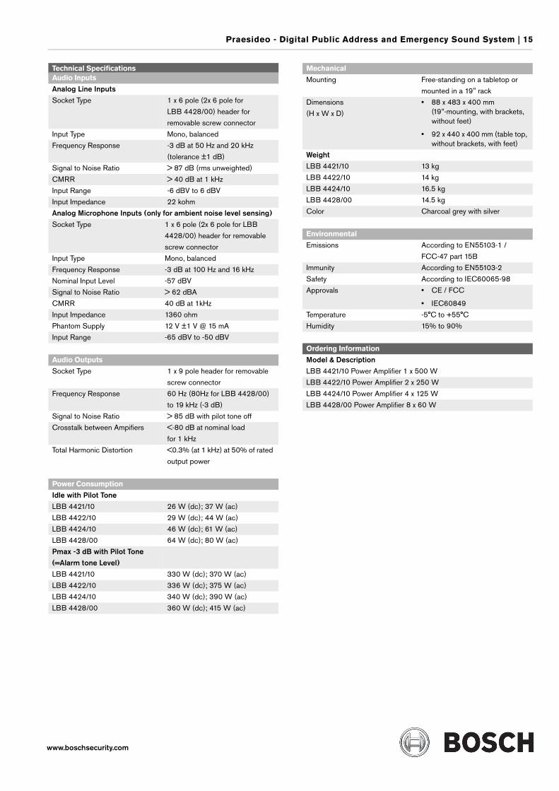
Technical SpecificationsAudio Inputs
Analog Line InputsSocket Type 1 x 6 pole (2x 6 pole for
LBB 4428/00) header for
removable screw connector
Input Type Mono, balanced
Frequency Response -3 dB at 50 Hz and 20 kHz
(tolerance ±1 dB)
Signal to Noise Ratio > 87 dB (rms unweighted)
CMRR > 40 dB at 1 kHz
Input Range -6 dBV to 6 dBV
Input Impedance 22 kohm
Analog Microphone Inputs (only for ambient noise level sensing)Socket Type 1 x 6 pole (2x 6 pole for LBB
4428/00) header for removable
screw connector
Input Type Mono, balanced
Frequency Response -3 dB at 100 Hz and 16 kHz
Nominal Input Level -57 dBV
Signal to Noise Ratio > 62 dBA
CMRR 40 dB at 1kHz
Input Impedance 1360 ohm
Phantom Supply 12 V ±1 V @ 15 mA
Input Range -65 dBV to -50 dBV
Audio Outputs
Socket Type 1 x 9 pole header for removable
screw connector
Frequency Response 60 Hz (80Hz for LBB 4428/00)
to 19 kHz (-3 dB)
Signal to Noise Ratio > 85 dB with pilot tone off
Crosstalk between Ampifiers <-80 dB at nominal load
for 1 kHz
Total Harmonic Distortion <0.3% (at 1 kHz) at 50% of rated
output power
Power Consumption
Idle with Pilot ToneLBB 4421/10 26 W (dc); 37 W (ac)
LBB 4422/10 29 W (dc); 44 W (ac)
LBB 4424/10 46 W (dc); 61 W (ac)
LBB 4428/00 64 W (dc); 80 W (ac)
Pmax -3 dB with Pilot Tone(=Alarm tone Level)LBB 4421/10 330 W (dc); 370 W (ac)
LBB 4422/10 336 W (dc); 375 W (ac)
LBB 4424/10 340 W (dc); 390 W (ac)
LBB 4428/00 360 W (dc); 415 W (ac)
Mechanical
Mounting Free-standing on a tabletop or
mounted in a 19" rack
Dimensions
(H x W x D)
• 88 x 483 x 400 mm (19”-mounting, with brackets, without feet)
• 92 x 440 x 400 mm (table top, without brackets, with feet)
WeightLBB 4421/10 13 kg
LBB 4422/10 14 kg
LBB 4424/10 16.5 kg
LBB 4428/00 14.5 kg
Color Charcoal grey with silver
Environmental
Emissions According to EN55103-1 /
FCC-47 part 15B
Immunity According to EN55103-2
Safety According to IEC60065-98
Approvals • CE / FCC
• IEC60849
Temperature -5°C to +55°C
Humidity 15% to 90%
Ordering Information
Model & DescriptionLBB 4421/10 Power Amplifier 1 x 500 W
LBB 4422/10 Power Amplifier 2 x 250 W
LBB 4424/10 Power Amplifier 4 x 125 W
LBB 4428/00 Power Amplifier 8 x 60 W
16 | Praesideo - Digital Public Address and Emergency Sound System
www.boschsecurity.com
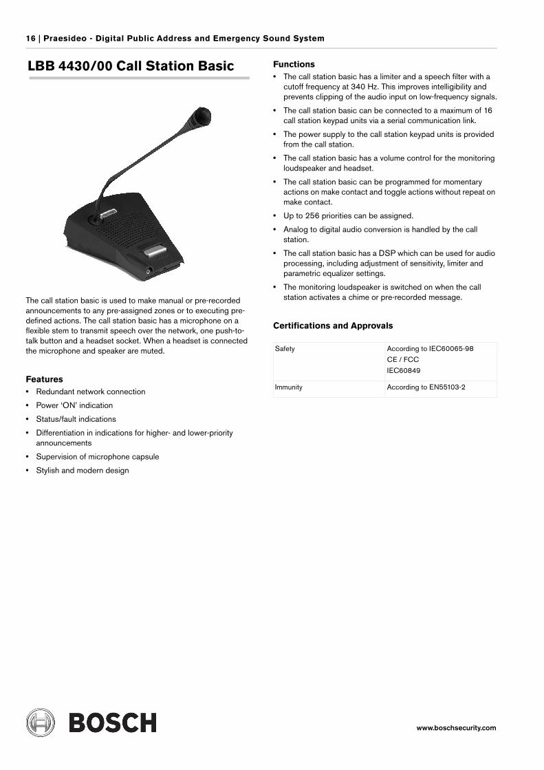
LBB 4430/00 Call Station Basic
The call station basic is used to make manual or pre-recorded announcements to any pre-assigned zones or to executing pre-defined actions. The call station basic has a microphone on a flexible stem to transmit speech over the network, one push-to-talk button and a headset socket. When a headset is connected the microphone and speaker are muted.
Features• Redundant network connection
• Power ‘ON’ indication
• Status/fault indications
• Differentiation in indications for higher- and lower-priority announcements
• Supervision of microphone capsule
• Stylish and modern design
Functions• The call station basic has a limiter and a speech filter with a
cutoff frequency at 340 Hz. This improves intelligibility and prevents clipping of the audio input on low-frequency signals.
• The call station basic can be connected to a maximum of 16 call station keypad units via a serial communication link.
• The power supply to the call station keypad units is provided from the call station.
• The call station basic has a volume control for the monitoring loudspeaker and headset.
• The call station basic can be programmed for momentary actions on make contact and toggle actions without repeat on make contact.
• Up to 256 priorities can be assigned.
• Analog to digital audio conversion is handled by the call station.
• The call station basic has a DSP which can be used for audio processing, including adjustment of sensitivity, limiter and parametric equalizer settings.
• The monitoring loudspeaker is switched on when the call station activates a chime or pre-recorded message.
Certifications and Approvals
Safety According to IEC60065-98
CE / FCC
IEC60849
Immunity According to EN55103-2
Praesideo - Digital Public Address and Emergency Sound System | 17
www.boschsecurity.com
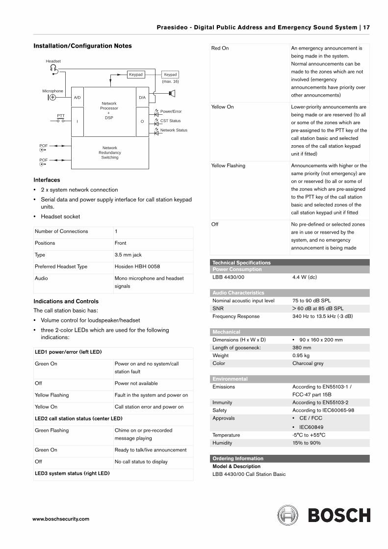
Installation/Configuration Notes
Interfaces
• 2 x system network connection
• Serial data and power supply interface for call station keypad units.
• Headset socket
Indications and Controls
The call station basic has:
• Volume control for loudspeaker/headset
• three 2-color LEDs which are used for the following indications:
Number of Connections 1
Positions Front
Type 3.5 mm jack
Preferred Headset Type Hosiden HBH 0058
Audio Mono microphone and headset
signals
LED1 power/error (left LED)
Green On Power on and no system/call
station fault
Off Power not available
Yellow Flashing Fault in the system and power on
Yellow On Call station error and power on
LED2 call station status (center LED)
Green Flashing Chime on or pre-recorded
message playing
Green On Ready to talk/live announcement
Off No call status to display
LED3 system status (right LED)
A/D D/A
Power/Error
Network
Processor
+
DSP
Keypad Keypad
(max. 16)
Headset
Microphone
PTT
POF
POF
Network
Redundancy
Switching
I O CST Status
Network Status
Red On An emergency announcement is
being made in the system.
Normal announcements can be
made to the zones which are not
involved (emergency
announcements have priority over
other announcements)
Yellow On Lower-priority announcements are
being made or are reserved (to all
or some of the zones which are
pre-assigned to the PTT key of the
call station basic and selected
zones of the call station keypad
unit if fitted)
Yellow Flashing Announcements with higher or the
same priority (not emergency) are
on or reserved (to all or some of
the zones which are pre-assigned
to the PTT key of the call station
basic and selected zones of the
call station keypad unit if fitted
Off No pre-defined or selected zones
are in use or reserved by the
system, and no emergency
announcement is being made
Technical SpecificationsPower Consumption
LBB 4430/00 4.4 W (dc)
Audio Characteristics
Nominal acoustic input level 75 to 90 dB SPL
SNR > 60 dB at 85 dB SPL
Frequency Response 340 Hz to 13.5 kHz (-3 dB)
Mechanical
Dimensions (H x W x D) • 90 x 160 x 200 mm
Length of gooseneck: 380 mm
Weight 0.95 kg
Color Charcoal grey
Environmental
Emissions According to EN55103-1 /
FCC-47 part 15B
Immunity According to EN55103-2
Safety According to IEC60065-98
Approvals • CE / FCC
• IEC60849
Temperature -5°C to +55°C
Humidity 15% to 90%
Ordering Information
Model & DescriptionLBB 4430/00 Call Station Basic
18 | Praesideo - Digital Public Address and Emergency Sound System
www.boschsecurity.com
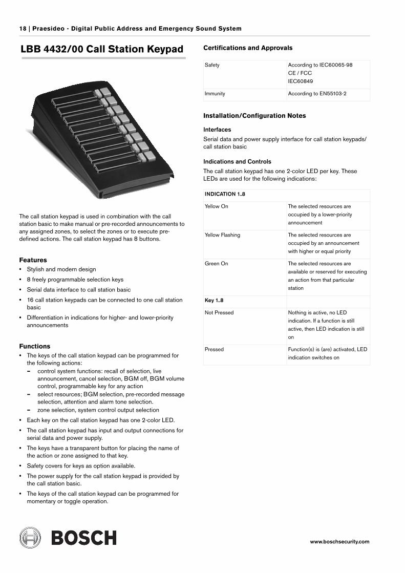
LBB 4432/00 Call Station Keypad
The call station keypad is used in combination with the call station basic to make manual or pre-recorded announcements to any assigned zones, to select the zones or to execute pre-defined actions. The call station keypad has 8 buttons.
Features• Stylish and modern design
• 8 freely programmable selection keys
• Serial data interface to call station basic
• 16 call station keypads can be connected to one call station basic
• Differentiation in indications for higher- and lower-priority announcements
Functions• The keys of the call station keypad can be programmed for
the following actions:– control system functions: recall of selection, live
announcement, cancel selection, BGM off, BGM volume control, programmable key for any action
– select resources; BGM selection, pre-recorded message selection, attention and alarm tone selection.
– zone selection, system control output selection
• Each key on the call station keypad has one 2-color LED.
• The call station keypad has input and output connections for serial data and power supply.
• The keys have a transparent button for placing the name of the action or zone assigned to that key.
• Safety covers for keys as option available.
• The power supply for the call station keypad is provided by the call station basic.
• The keys of the call station keypad can be programmed for momentary or toggle operation.
Certifications and Approvals
Installation/Configuration Notes
Interfaces
Serial data and power supply interface for call station keypads/call station basic
Indications and Controls
The call station keypad has one 2-color LED per key. These LEDs are used for the following indications:
Safety According to IEC60065-98
CE / FCC
IEC60849
Immunity According to EN55103-2
INDICATION 1..8
Yellow On The selected resources are
occupied by a lower-priority
announcement
Yellow Flashing The selected resources are
occupied by an announcement
with higher or equal priority
Green On The selected resources are
available or reserved for executing
an action from that particular
station
Key 1..8
Not Pressed Nothing is active, no LED
indication. If a function is still
active, then LED indication is still
on
Pressed Function(s) is (are) activated, LED
indication switches on
Praesideo - Digital Public Address and Emergency Sound System | 19
www.boschsecurity.com
Technical SpecificationsPower Consumption
LBB 4432/00 1.1W (dc)
Mechanical
Mounting • By fixing bracket to the call station basic
Dimensions (H x W x D) 70 x 95 x 200 mm
Weight 0.3 kg
Color Charcoal grey
Environmental
Emissions According to EN55103-1 /
FCC-47 part 15B
Immunity According to EN55103-2
Safety According to IEC60065-98
Approvals • CE / FCC
• IEC60849
Temperature -5°C to +55°C
Humidity 15% to 90%
Ordering Information
Model & DescriptionLBB 4432/00 Call Station Keypad
20 | Praesideo - Digital Public Address and Emergency Sound System
www.boschsecurity.com
LBB 4433/00 Call Station Kit
The call station kit is used to make custom-made call stations. These can be used to make manual or pre-recorded announcements to any pre-assigned zones or to execute pre-defined actions. The call station kit has two control inputs and a connector for microphone, headphone and volume control. When a headset is connected the microphone is muted. An external power supply can be connected to the call station kit.
Features• Redundant network connection
• Power ‘ON’ outputs
• Status/fault outputs
• Monitoring loudspeaker output
• Separate indication outputs for higher- and lower-priority announcements
• Supervision of microphone
Functions• The call station kit has a limiter and a speech filter with a
cutoff frequency at 340 Hz. This improves intelligibility and prevents clipping of the audio input on low-frequency signals.
• The call station unit kit can be connected to a maximum of 16 call station keypads or keypad kits with serial data communication.
• The call station kit has a volume control input for both the monitoring loudspeaker and the headset.
• The call station kit control input can be programmed for momentary or toggle operation. The control inputs are monitored for short-circuits and open-circuits.
• Up to 256 priorities can be assigned.
• Analog to digital audio conversion is handled by the call station kit.
• The call station kit has a DSP which can be used for audio processing, including adjustment of sensitivity, limiter and parametric equalize settings.
Installation/Configuration Notes
Interfaces
• 2 x system network connection
• Serial data and power supply interface for call station keypad units
• Connector for microphone, headphone and volume control
• Backup supply input and 2 control inputs
Indications and Controls
• Volume control for loudspeaker/headset
• Connection for the control inputs
• Five LED outputs to which lamps or relays can be connected. These LEDs are used for the following indications:– Power on, no system/call station kit fault– Power not available– Fault in the system– Call station kit error– No error status– Chime on or pre-recorded message playing– Ready to talk/live announcement– No call status to display
• An emergency announcement is being made in the system
• Normal calls can be made to the zones which are not involved (emergency announcements have priority over other announcements)
• Lower-priority announcements are being made to all or some of the zones which are pre-assigned to the PTT key of the call station and selected zones of the call station extension unit if fitted)
• Announcements with higher or the same priority (not emergency) are being made (to all or some of the zones which are pre-assigned to the PTT key of the call station and selected zones of the call station extension unit, if fitted)
• No announcements are being made to the pre-defined zones (including emergency announcements)
Technical SpecificationsPower Consumption
LBB 4433/00 7.2 W (dc) excl. indicators
Audio Characteristics
Nominal acoustic input level 75 to 90 dB SPL
SNR > 60 dB at 85 dB SPL
Frequency Response 340 Hz to 13.5 kHz (-3 dB)
Mechanical
Mounting • PCB with 6 mounting holes
Dimensions (H x W x D) • 130 x 118 x 20 mm
Weight 120 g
Ordering Information
Model & DescriptionLBB 4433/00 Call Station Kit

Praesideo - Digital Public Address and Emergency Sound System | 21
www.boschsecurity.com
LBB 4434/00 Call Station Keypad Kit
The call station keypad kit is used in combination with a call station kit or call station basic to make manual or pre-recorded announcements to any assigned zones, or to execute pre-defined actions. The call station keypad has 8 input connections with corresponding 16 output connections, all freely programmable.
Features• 8 freely programmable logical inputs
• 16 freely programmable logical outputs
• Serial interface to call station kit
• 16 call station keypad kits can be connected to one call station kit/call station basic
Functions• The keys of the call station keypad kit can be programmed for
the following actions:– control system functions: recall of selection, live
announcement, cancel selection, BGM off, BGM volume control, programmable key for any action
– select resources; BGM selection, pre-recorded message selection, attention and alarm tone selection.
– zone selection, system control output selection
• Each key of the call station keypad kit has two related contacts
• The call station keypad kit has input and output connections for the serial connection
• The power supply for the call station keypad kit can be provided by the call station
• The keys of the call station keypad kit can be programmed for momentary or toggle operation
Installation/Configuration Notes
Interfaces
Serial data and power supply connection for call station keypad units
Indications and Controls
• The call station keypad has 16 control outputs which can be programmed for any zone status, function status or faults
• The call station input can be programmed for all the functions specified for the call station keypad
• Call macros can be assigned to any of the inputs of the call station keypad kit
• Once the control input is used for any function, the control output will be linked to the specific action to be initiated by that input
Technical SpecificationsPower Consumption
LBB 4434/00 1.2 W (dc) excl. indicators
Mechanical
Mounting • PCB with 6 mounting holes
Dimensions (H x W x D) • 60 x 90 x 20 mm
Weight 55 g
Ordering Information
Model & DescriptionLBB 4434/00 Call Station Keypad Kit
22 | Praesideo - Digital Public Address and Emergency Sound System
www.boschsecurity.com
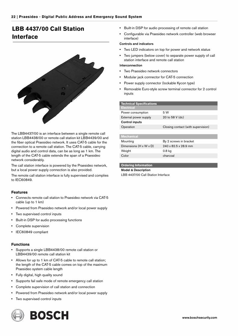
LBB 4437/00 Call Station Interface
The LBB4437/00 is an interface between a single remote call station LBB4438/00 or remote call station kit LBB4439/00 and the fiber optical Praesideo network. It uses CAT-5 cable for the connection to a remote call station. The CAT-5 cable, carrying digital audio and control data, can be as long as 1 km. The length of the CAT-5 cable extends the span of a Praesideo network considerably.
The call station interface is powered by the Praesideo network, but a local power supply connection is also provided.
The remote call station interface is fully supervised and complies to IEC60849.
Features• Connects remote call station to Praesideo network via CAT-5
cable (up to 1 km)
• Powered from Praesideo network and/or local power supply
• Two supervised control inputs
• Built-in DSP for audio processing functions
• Complete supervision
• IEC60849 compliant
Functions• Supports a single LBB4438/00 remote call station or
LBB4439/00 remote call station kit
• Allows for up to 1 km of CAT-5 cable to remote call station; the length of the CAT-5 cable comes on top of the maximum Praesideo system cable length
• Fully digital, high quality sound
• Supports fail safe mode of remote emergency call station
• Complete supervision of call station and connection
• Powered from Praesideo network and/or local power supply
• Two supervised control inputs
• Built-in DSP for audio processing of remote call station
• Configurable via Praesideo network controller (web browser interface)
Controls and indicators
• Two LED indicators on top for power and network status
• Two jumpers (below cover) to separate power supply of call station interface and remote call station
Interconnection
• Two Praesideo network connectors
• Modular jack connector for CAT-5 connection
• Power supply connector (lockable Kycon type)
• Removable Euro-style screw terminal connector for 2 control inputs
Technical SpecificationsElectrical
Power consumption 5 W
External power supply 20 to 58 V (dc)
Control inputsOperation Closing contact (with supervision)
Mechanical
Mounting By 2 screws in bracket
Dimensions (H x W x D) 240 x 82.5 x 28.9 mm
Weight 0.8 kg
Color charcoal
Ordering Information
Model & DescriptionLBB 4437/00 Call Station Interface
Praesideo - Digital Public Address and Emergency Sound System | 23
www.boschsecurity.com
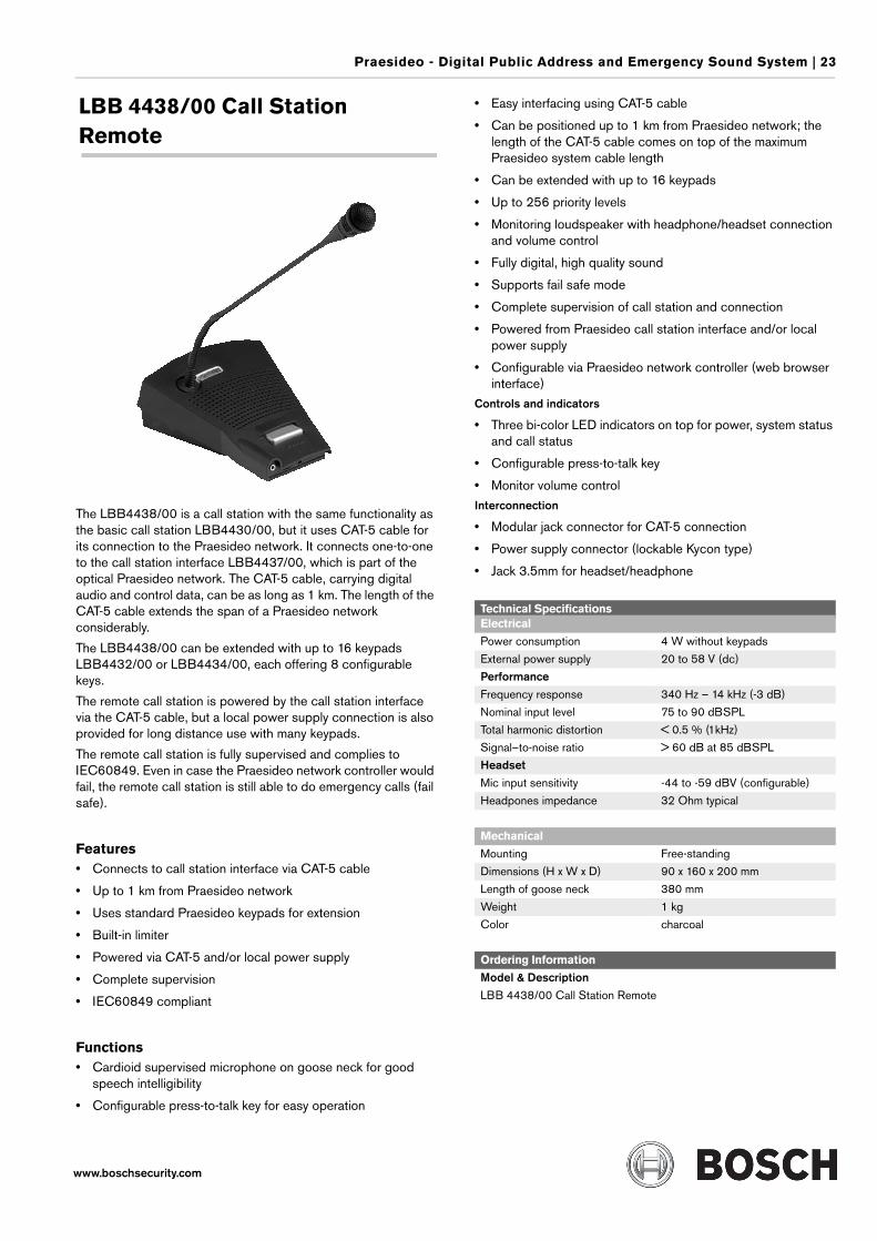
LBB 4438/00 Call Station Remote
The LBB4438/00 is a call station with the same functionality as the basic call station LBB4430/00, but it uses CAT-5 cable for its connection to the Praesideo network. It connects one-to-one to the call station interface LBB4437/00, which is part of the optical Praesideo network. The CAT-5 cable, carrying digital audio and control data, can be as long as 1 km. The length of the CAT-5 cable extends the span of a Praesideo network considerably.
The LBB4438/00 can be extended with up to 16 keypads LBB4432/00 or LBB4434/00, each offering 8 configurable keys.
The remote call station is powered by the call station interface via the CAT-5 cable, but a local power supply connection is also provided for long distance use with many keypads.
The remote call station is fully supervised and complies to IEC60849. Even in case the Praesideo network controller would fail, the remote call station is still able to do emergency calls (fail safe).
Features• Connects to call station interface via CAT-5 cable
• Up to 1 km from Praesideo network
• Uses standard Praesideo keypads for extension
• Built-in limiter
• Powered via CAT-5 and/or local power supply
• Complete supervision
• IEC60849 compliant
Functions• Cardioid supervised microphone on goose neck for good
speech intelligibility
• Configurable press-to-talk key for easy operation
• Easy interfacing using CAT-5 cable
• Can be positioned up to 1 km from Praesideo network; the length of the CAT-5 cable comes on top of the maximum Praesideo system cable length
• Can be extended with up to 16 keypads
• Up to 256 priority levels
• Monitoring loudspeaker with headphone/headset connection and volume control
• Fully digital, high quality sound
• Supports fail safe mode
• Complete supervision of call station and connection
• Powered from Praesideo call station interface and/or local power supply
• Configurable via Praesideo network controller (web browser interface)
Controls and indicators
• Three bi-color LED indicators on top for power, system status and call status
• Configurable press-to-talk key
• Monitor volume controlInterconnection
• Modular jack connector for CAT-5 connection
• Power supply connector (lockable Kycon type)
• Jack 3.5mm for headset/headphone
Technical SpecificationsElectrical
Power consumption 4 W without keypads
External power supply 20 to 58 V (dc)
PerformanceFrequency response 340 Hz – 14 kHz (-3 dB)
Nominal input level 75 to 90 dBSPL
Total harmonic distortion < 0.5 % (1kHz)
Signal–to-noise ratio > 60 dB at 85 dBSPL
HeadsetMic input sensitivity -44 to -59 dBV (configurable)
Headpones impedance 32 Ohm typical
Mechanical
Mounting Free-standing
Dimensions (H x W x D) 90 x 160 x 200 mm
Length of goose neck 380 mm
Weight 1 kg
Color charcoal
Ordering Information
Model & DescriptionLBB 4438/00 Call Station Remote
24 | Praesideo - Digital Public Address and Emergency Sound System
www.boschsecurity.com
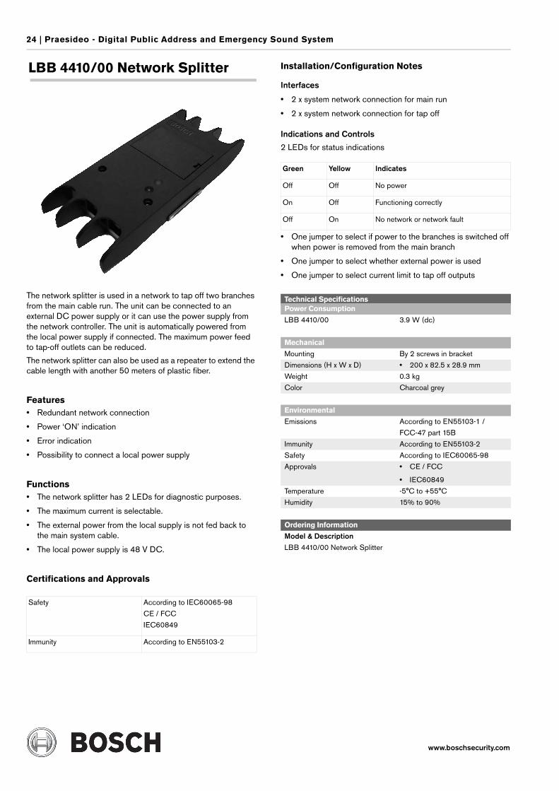
LBB 4410/00 Network Splitter
The network splitter is used in a network to tap off two branches from the main cable run. The unit can be connected to an external DC power supply or it can use the power supply from the network controller. The unit is automatically powered from the local power supply if connected. The maximum power feed to tap-off outlets can be reduced.
The network splitter can also be used as a repeater to extend the cable length with another 50 meters of plastic fiber.
Features• Redundant network connection
• Power ‘ON’ indication
• Error indication
• Possibility to connect a local power supply
Functions• The network splitter has 2 LEDs for diagnostic purposes.
• The maximum current is selectable.
• The external power from the local supply is not fed back to the main system cable.
• The local power supply is 48 V DC.
Certifications and Approvals
Installation/Configuration Notes
Interfaces
• 2 x system network connection for main run
• 2 x system network connection for tap off
Indications and Controls
2 LEDs for status indications
• One jumper to select if power to the branches is switched off when power is removed from the main branch
• One jumper to select whether external power is used
• One jumper to select current limit to tap off outputs
Safety According to IEC60065-98
CE / FCC
IEC60849
Immunity According to EN55103-2
Green Yellow Indicates
Off Off No power
On Off Functioning correctly
Off On No network or network fault
Technical SpecificationsPower Consumption
LBB 4410/00 3.9 W (dc)
Mechanical
Mounting By 2 screws in bracket
Dimensions (H x W x D) • 200 x 82.5 x 28.9 mm
Weight 0.3 kg
Color Charcoal grey
Environmental
Emissions According to EN55103-1 /
FCC-47 part 15B
Immunity According to EN55103-2
Safety According to IEC60065-98
Approvals • CE / FCC
• IEC60849
Temperature -5°C to +55°C
Humidity 15% to 90%
Ordering Information
Model & DescriptionLBB 4410/00 Network Splitter
Praesideo - Digital Public Address and Emergency Sound System | 25
www.boschsecurity.com
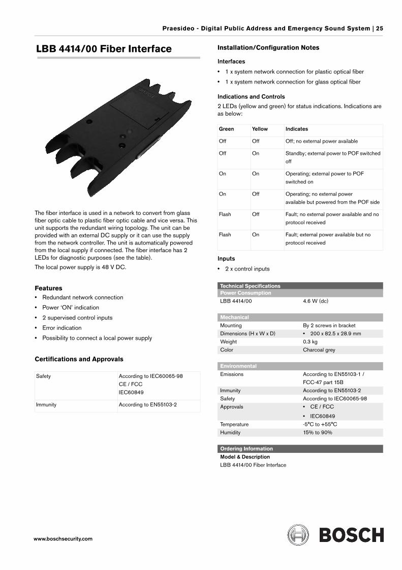
LBB 4414/00 Fiber Interface
The fiber interface is used in a network to convert from glass fiber optic cable to plastic fiber optic cable and vice versa. This unit supports the redundant wiring topology. The unit can be provided with an external DC supply or it can use the supply from the network controller. The unit is automatically powered from the local supply if connected. The fiber interface has 2 LEDs for diagnostic purposes (see the table).
The local power supply is 48 V DC.
Features• Redundant network connection
• Power ‘ON’ indication
• 2 supervised control inputs
• Error indication
• Possibility to connect a local power supply
Certifications and Approvals
Installation/Configuration Notes
Interfaces
• 1 x system network connection for plastic optical fiber
• 1 x system network connection for glass optical fiber
Indications and Controls
2 LEDs (yellow and green) for status indications. Indications are as below:
Inputs
• 2 x control inputs
Safety According to IEC60065-98
CE / FCC
IEC60849
Immunity According to EN55103-2
Green Yellow Indicates
Off Off Off; no external power available
Off On Standby; external power to POF switched
off
On On Operating; external power to POF
switched on
On Off Operating; no external power
available but powered from the POF side
Flash Off Fault; no external power available and no
protocol received
Flash On Fault; external power available but no
protocol received
Technical SpecificationsPower Consumption
LBB 4414/00 4.6 W (dc)
Mechanical
Mounting By 2 screws in bracket
Dimensions (H x W x D) • 200 x 82.5 x 28.9 mm
Weight 0.3 kg
Color Charcoal grey
Environmental
Emissions According to EN55103-1 /
FCC-47 part 15B
Immunity According to EN55103-2
Safety According to IEC60065-98
Approvals • CE / FCC
• IEC60849
Temperature -5°C to +55°C
Humidity 15% to 90%
Ordering Information
Model & DescriptionLBB 4414/00 Fiber Interface
26 | Praesideo - Digital Public Address and Emergency Sound System
www.boschsecurity.com
LBB 4416/xx Network Cables
Installation/Configuration NotesThe network cables are supplied in different lengths. The extension of the type number indicates the length of the cable. Only the LBB 4416/00 is without connectors. The connectors are available separately (LBB 4417/00).
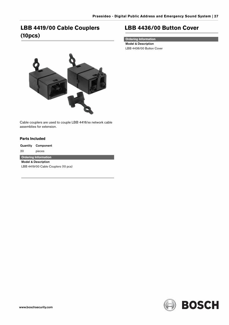
LBB 4417/00 Set Network Connectors
The set network connectors contains 20 connectors that can be used with the network cable LBB 4416/00.
For assembly the cable/connector toolkit LBB 4418/00 is required.
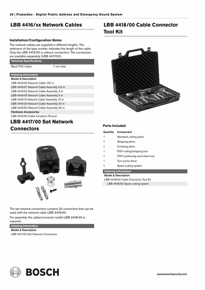
LBB 4418/00 Cable Connector Tool Kit
Parts Included
Technical Specifications
Black PVC Cable 7 mm (dia)
Ordering Information
Model & DescriptionLBB 4416/00 Network Cable 100 m
LBB 4416/01 Network Cable Assembly 0,5 m
LBB 4416/02 Network Cable Assembly 2 m
LBB 4416/05 Network Cable Assembly 5 m
LBB 4416/10 Network Cable Assembly 10 m
LBB 4416/20 Network Cable Assembly 20 m
LBB 4416/50 Network Cable Assembly 50 m
Hardware AccessoriesLBB 4419/00 Cable Couplers (10 pcs)
Ordering Information
Model & DescriptionLBB 4417/00 Set Network Connectors
Quantity Component
1 Standard cutting pliers
1 Stripping pliers
1 Crimping pliers
1 POF cutting/stripping tool
1 POF positioning and indent tool
1 Torx screw driver
1 Spare cutting system
Ordering Information
Model & DescriptionLBB 4418/00 Cable Connector Tool Kit
LBB 4418/50 Spare cutting system
Praesideo - Digital Public Address and Emergency Sound System | 27
www.boschsecurity.com
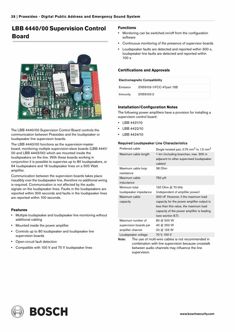
LBB 4419/00 Cable Couplers (10pcs)
Cable couplers are used to couple LBB 4416/xx network cable assemblies for extension.
Parts Included
LBB 4436/00 Button Cover
Quantity Component
20 pieces
Ordering Information
Model & DescriptionLBB 4419/00 Cable Couplers (10 pcs)
Ordering Information
Model & DescriptionLBB 4436/00 Button Cover
28 | Praesideo - Digital Public Address and Emergency Sound System
www.boschsecurity.com
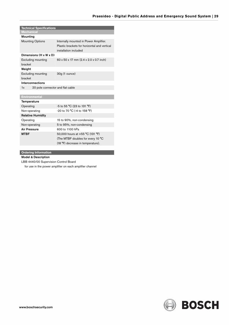
LBB 4440/00 Supervision Control Board
The LBB 4440/00 Supervision Control Board controls the communication between Praesideo and the loudspeaker or loudspeaker line supervision boards.
The LBB 4440/00 functions as the supervision-master board, monitoring multiple supervision-slave boards (LBB 4441/00 and LBB 4443/00) which are mounted inside the loudspeakers on the line. With these boards working in conjunction it is possible to supervise up to 80 loudspeakers, or 64 loudspeakers and 16 loudspeaker lines on a 500 Watt amplifier.
Communication between the supervision boards takes place inaudibly over the loudspeaker line, therefore no additional wiring is required. Communication is not affected by the audio signals on the loudspeaker lines. Faults in the loudspeakers are reported within 300 seconds and faults in the loudspeaker lines are reported within 100 seconds.
Features• Multiple loudspeaker and loudspeaker line monitoring without
additional cabling
• Mounted inside the power amplifier
• Controls up to 80 loudspeaker and loudspeaker line supervision boards
• Open-circuit fault detection
• Compatible with 100 V and 70 V loudspeaker lines
Functions• Monitoring can be switched on/off from the configuration
software
• Continuous monitoring of the presence of supervisor boards
• Loudspeaker faults are detected and reported within 300 s, loudspeaker line faults are detected and reported within 100 s
Certifications and Approvals
Installation/Configuration NotesThe following power amplifiers have a provision for installing a supervision control board:
• LBB 4421/10
• LBB 4422/10
• LBB 4424/10
Required Loudspeaker Line Characteristics
Note: The use of multi-wire cables is not recommended in combination with line supervision because crosstalk between audio channels may influence the line supervision.
Electromagnetic Compatibility
Emission EN55103-1/FCC-47part 15B
Immunity EN55103-2
Preferred cable Single twisted pair, 0.75 mm2 to 1.5 mm2
Maximum cable length 1 km (including branches, max. 300 m
adjacent to other supervised loudspeaker
cables)
Maximum cable loop
resistance
38 Ohm
Maximum cable
inductance
750 µH
Minimum total
loudspeaker impedance
120 Ohm @ 70 kHz
(independent of amplifier power)
Maximum cable
capacity
300 nF. However, if the maximum load
capacity for the power amplifier output is
less than this value, the maximum load
capacity of the power amplifier is leading
(see section 8.7).
Maximum number of
supervision boards per
amplifier channel
80 @ 500 W
40 @ 250 W
20 @ 125 W
Loudspeaker voltage 70 V, 100 V
Praesideo - Digital Public Address and Emergency Sound System | 29
www.boschsecurity.com
Technical SpecificationsMechanical
Mounting Mounting Options Internally mounted in Power Amplifier.
Plastic brackets for horizontal and vertical
installation included
Dimensions (H x W x D) Excluding mounting
bracket
60 x 50 x 17 mm (2.4 x 2.0 x 0.7 inch)
WeightExcluding mounting
bracket
30g (1 ounce)
Interconnections1x 20 pole connector and flat cable
Environmental
Temperature Operating -5 to 55 °C (23 to 131 °F)
Non-operating -20 to 70 °C (-4 to 158 °F)
Relative Humidity Operating 15 to 90%, non-condensing
Non-operating 5 to 95%, non-condensing
Air Pressure 600 to 1100 hPa
MTBF 50,000 hours at +55 °C (131 °F)
(The MTBF doubles for every 10 °C
(18 °F) decrease in temperature).
Ordering Information
Model & DescriptionLBB 4440/00 Supervision Control Board
for use in the power amplifier on each amplifier channel
30 | Praesideo - Digital Public Address and Emergency Sound System
www.boschsecurity.com
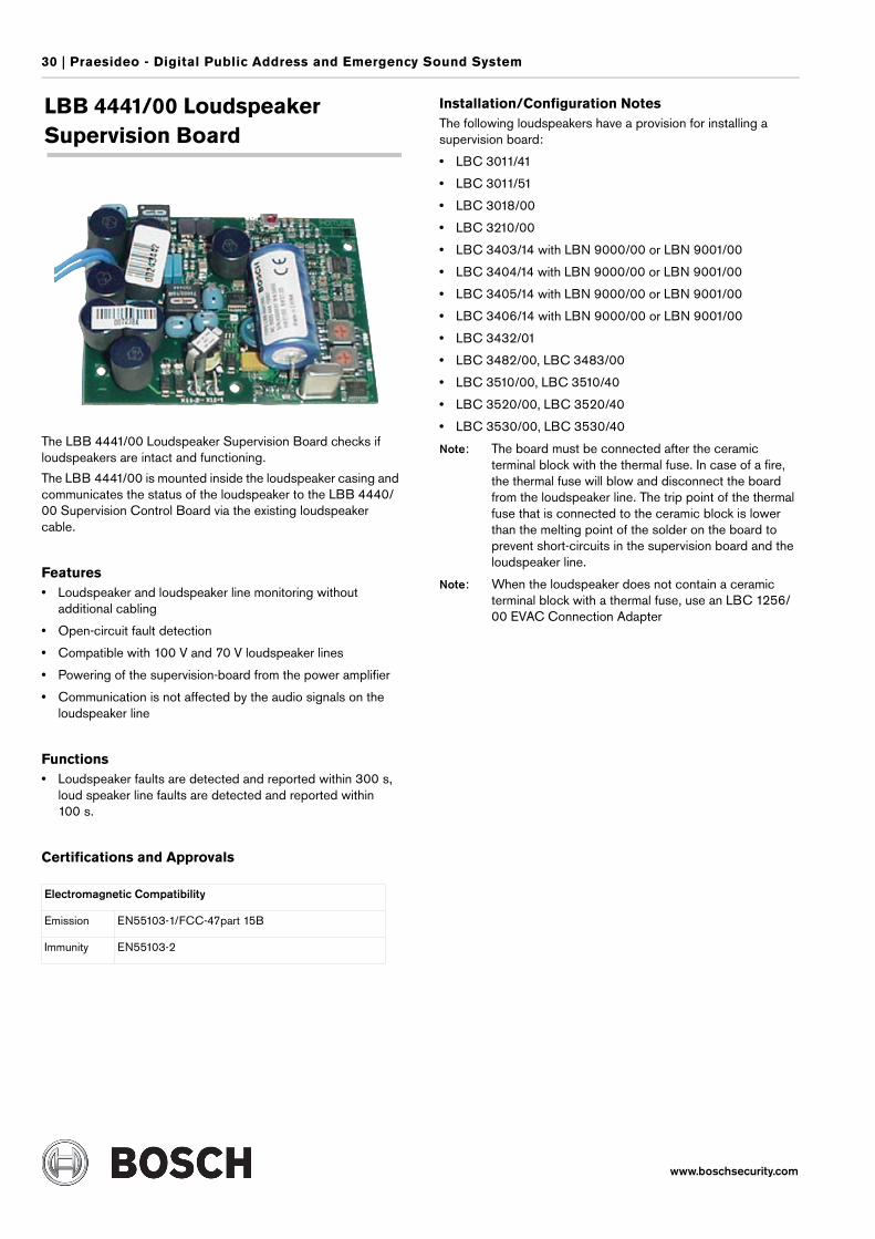
LBB 4441/00 Loudspeaker Supervision Board
The LBB 4441/00 Loudspeaker Supervision Board checks if loudspeakers are intact and functioning.
The LBB 4441/00 is mounted inside the loudspeaker casing and communicates the status of the loudspeaker to the LBB 4440/00 Supervision Control Board via the existing loudspeaker cable.
Features• Loudspeaker and loudspeaker line monitoring without
additional cabling
• Open-circuit fault detection
• Compatible with 100 V and 70 V loudspeaker lines
• Powering of the supervision-board from the power amplifier
• Communication is not affected by the audio signals on the loudspeaker line
Functions• Loudspeaker faults are detected and reported within 300 s,
loud speaker line faults are detected and reported within 100 s.
Certifications and Approvals
Installation/Configuration NotesThe following loudspeakers have a provision for installing a supervision board:
• LBC 3011/41
• LBC 3011/51
• LBC 3018/00
• LBC 3210/00
• LBC 3403/14 with LBN 9000/00 or LBN 9001/00
• LBC 3404/14 with LBN 9000/00 or LBN 9001/00
• LBC 3405/14 with LBN 9000/00 or LBN 9001/00
• LBC 3406/14 with LBN 9000/00 or LBN 9001/00
• LBC 3432/01
• LBC 3482/00, LBC 3483/00
• LBC 3510/00, LBC 3510/40
• LBC 3520/00, LBC 3520/40
• LBC 3530/00, LBC 3530/40
Note: The board must be connected after the ceramic terminal block with the thermal fuse. In case of a fire, the thermal fuse will blow and disconnect the board from the loudspeaker line. The trip point of the thermal fuse that is connected to the ceramic block is lower than the melting point of the solder on the board to prevent short-circuits in the supervision board and the loudspeaker line.
Note: When the loudspeaker does not contain a ceramic terminal block with a thermal fuse, use an LBC 1256/00 EVAC Connection Adapter
Electromagnetic Compatibility
Emission EN55103-1/FCC-47part 15B
Immunity EN55103-2
Praesideo - Digital Public Address and Emergency Sound System | 31
www.boschsecurity.com
Technical SpecificationsMechanical
Mounting Mounting Options Internally mounted in the Loudspeaker.
An optional mounting bracket,
LBB 4446/00 is available.
Dimensions (H x W x D) Board only 78 x 60 x 22 mm (3.0 x 2.3 x 0.8 inch)
WeightBoard only 70g (2.4 ounces)
Interconnections2x 30 cm flying leads
2x faston connectors
Environmental
Temperature Operating, guaranteed -5 to 55 °C (23 to 131 °F)
Operating, sample
tested
-15 to 55 °C (5 to 131 °F)
Non-operating -20 to 70 °C (-4 to 158 °F)
Relative Humidity Operating 15 to 90%, non-condensing
Non-operating 5 to 95%, non-condensing
Air Pressure 600 to 1100 hPa
MTBF 50,000 hours at +55 °C (131 °F)
(The MTBF doubles for every 10 °C
(18 °F) decrease in temperature).
Ordering Information
Model & DescriptionLBB 4441/00 Loudspeaker Supervision Board
LBB 4446/00 Brackets (10 pcs)
32 | Praesideo - Digital Public Address and Emergency Sound System
www.boschsecurity.com
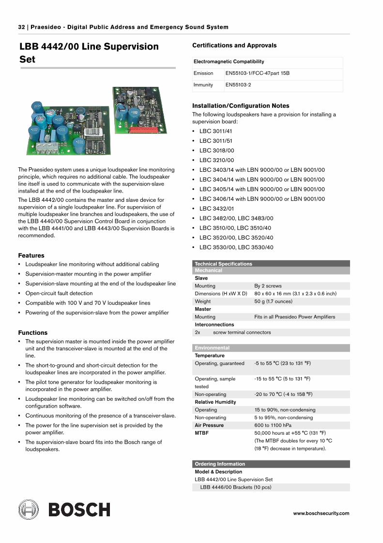
LBB 4442/00 Line Supervision Set
The Praesideo system uses a unique loudspeaker line monitoring principle, which requires no additional cable. The loudspeaker line itself is used to communicate with the supervision-slave installed at the end of the loudspeaker line.
The LBB 4442/00 contains the master and slave device for supervision of a single loudspeaker line. For supervision of multiple loudspeaker line branches and loudspeakers, the use of the LBB 4440/00 Supervision Control Board in conjunction with the LBB 4441/00 and LBB 4443/00 Supervision Boards is recommended.
Features• Loudspeaker line monitoring without additional cabling
• Supervision-master mounting in the power amplifier
• Supervision-slave mounting at the end of the loudspeaker line
• Open-circuit fault detection
• Compatible with 100 V and 70 V loudspeaker lines
• Powering of the supervision-slave from the power amplifier
Functions• The supervision master is mounted inside the power amplifier
unit and the transceiver-slave is mounted at the end of the line.
• The short-to-ground and short-circuit detection for the loudspeaker lines are incorporated in the power amplifier.
• The pilot tone generator for loudspeaker monitoring is incorporated in the power amplifier.
• Loudspeaker line monitoring can be switched on/off from the configuration software.
• Continuous monitoring of the presence of a transceiver-slave.
• The power for the line supervision set is provided by the power amplifier.
• The supervision-slave board fits into the Bosch range of loudspeakers.
Certifications and Approvals
Installation/Configuration NotesThe following loudspeakers have a provision for installing a supervision board:
• LBC 3011/41
• LBC 3011/51
• LBC 3018/00
• LBC 3210/00
• LBC 3403/14 with LBN 9000/00 or LBN 9001/00
• LBC 3404/14 with LBN 9000/00 or LBN 9001/00
• LBC 3405/14 with LBN 9000/00 or LBN 9001/00
• LBC 3406/14 with LBN 9000/00 or LBN 9001/00
• LBC 3432/01
• LBC 3482/00, LBC 3483/00
• LBC 3510/00, LBC 3510/40
• LBC 3520/00, LBC 3520/40
• LBC 3530/00, LBC 3530/40
Electromagnetic Compatibility
Emission EN55103-1/FCC-47part 15B
Immunity EN55103-2
Technical SpecificationsMechanical
SlaveMounting By 2 screws
Dimensions (H xW X D) 80 x 60 x 16 mm (3.1 x 2.3 x 0.6 inch)
Weight 50 g (1.7 ounces)
MasterMounting Fits in all Praesideo Power Amplifiers
Interconnections2x screw terminal connectors
Environmental
Temperature Operating, guaranteed -5 to 55 °C (23 to 131 °F)
Operating, sample
tested
-15 to 55 °C (5 to 131 °F)
Non-operating -20 to 70 °C (-4 to 158 °F)
Relative Humidity Operating 15 to 90%, non-condensing
Non-operating 5 to 95%, non-condensing
Air Pressure 600 to 1100 hPa
MTBF 50,000 hours at +55 °C (131 °F)
(The MTBF doubles for every 10 °C
(18 °F) decrease in temperature).
Ordering Information
Model & DescriptionLBB 4442/00 Line Supervision Set
LBB 4446/00 Brackets (10 pcs)
Praesideo - Digital Public Address and Emergency Sound System | 33
www.boschsecurity.com
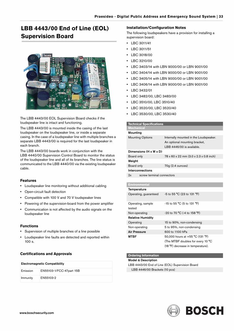
LBB 4443/00 End of Line (EOL) Supervision Board
The LBB 4443/00 EOL Supervision Board checks if the loudspeaker line is intact and functioning.
The LBB 4443/00 is mounted inside the casing of the last loudspeaker on the loudspeaker line, or inside a separate casing. In the case of a loudspeaker line with multiple branches a separate LBB 4443/00 is required for the last loudspeaker in each branch.
The LBB 4443/00 boards work in conjunction with the LBB 4440/00 Supervision Control Board to monitor the status of the loudspeaker line and all of its branches. The line status is communicated to the LBB 4440/00 via the existing loudspeaker cable.
Features• Loudspeaker line monitoring without additional cabling
• Open-circuit fault detection
• Compatible with 100 V and 70 V loudspeaker lines
• Powering of the supervision-board from the power amplifier
• Communication is not affected by the audio signals on the loudspeaker line
Functions• Supervision of multiple branches of a line possible
• Loudspeaker line faults are detected and reported within 100 s.
Certifications and Approvals
Installation/Configuration NotesThe following loudspeakers have a provision for installing a supervision board:
• LBC 3011/41
• LBC 3011/51
• LBC 3018/00
• LBC 3210/00
• LBC 3403/14 with LBN 9000/00 or LBN 9001/00
• LBC 3404/14 with LBN 9000/00 or LBN 9001/00
• LBC 3405/14 with LBN 9000/00 or LBN 9001/00
• LBC 3406/14 with LBN 9000/00 or LBN 9001/00
• LBC 3432/01
• LBC 3482/00, LBC 3483/00
• LBC 3510/00, LBC 3510/40
• LBC 3520/00, LBC 3520/40
• LBC 3530/00, LBC 3530/40
Electromagnetic Compatibility
Emission EN55103-1/FCC-47part 15B
Immunity EN55103-2
Technical SpecificationsMechanical
Mounting Mounting Options Internally mounted in the Loudspeaker.
An optional mounting bracket,
LBB 4446/00 is available.
Dimensions (H x W x D) Board only 78 x 60 x 22 mm (3.0 x 2.3 x 0.8 inch)
WeightBoard only 70g (2.4 ounces)
Interconnections2x screw terminal connectors
Environmental
Temperature Operating, guaranteed -5 to 55 °C (23 to 131 °F)
Operating, sample
tested
-15 to 55 °C (5 to 131 °F)
Non-operating -20 to 70 °C (-4 to 158 °F)
Relative Humidity Operating 15 to 90%, non-condensing
Non-operating 5 to 95%, non-condensing
Air Pressure 600 to 1100 hPa
MTBF 50,000 hours at +55 °C (131 °F)
(The MTBF doubles for every 10 °C
(18 °F) decrease in temperature).
Ordering Information
Model & DescriptionLBB 4443/00 End of Line (EOL) Supervision Board
LBB 4446/00 Brackets (10 pcs)
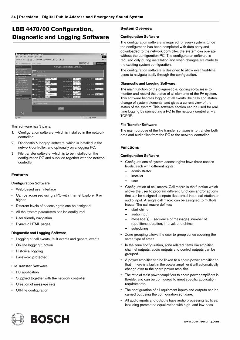
34 | Praesideo - Digital Public Address and Emergency Sound System
www.boschsecurity.com
LBB 4470/00 Configuration, Diagnostic and Logging Software
This software has 3 parts.
1. Configuration software, which is installed in the network controller.
2. Diagnostic & logging software, which is installed in the network controller, and optionally on a logging PC.
3. File transfer software, which is to be installed on the configuration PC and supplied together with the network controller.
Features
Configuration Software
• Web-based user interface
• Can be accessed using a PC with Internet Explorer 6 or higher
• Different levels of access rights can be assigned
• All the system parameters can be configured
• User-friendly navigation
• Dynamic HTML pages
Diagnostic and Logging Software
• Logging of call events, fault events and general events
• On-line logging function
• Historical logging
• Password-protected
File Transfer Software
• PC application
• Supplied together with the network controller
• Creation of message sets
• Off-line configuration
System Overview
Configuration Software
The configuration software is required for every system. Once the configuration has been completed with data entry and downloaded to the network controller, the system can operate without the configuration PC. The configuration software is required only during installation and when changes are made to the existing system configuration.
The configuration software is designed to allow even first-time users to navigate easily through the configuration.
Diagnostic and Logging Software
The main function of the diagnostic & logging software is to monitor and record the status of all elements of the PA system. This software handles logging of all events like calls and status change of system elements, and gives a current view of the status of the system. This software section can be used for real-time logging by connecting a PC to the network controller, via TCP/IP.
File Transfer Software
The main purpose of the file transfer software is to transfer both data and audio files from the PC to the network controller.
Functions
Configuration Software
• Configurations of system access rights have three access levels, each with different rights:– administrator– installer– user
• Configuration of call macro. Call macro is the function which allows the user to program different functions and/or actions that can be assigned to inputs like control input, call station or audio input. A single call macro can be assigned to multiple inputs. The call macro defines:– start chime– audio input– message(s) – sequence of messages, number of
repetitions, duration, interval, end chime– scheduling
• Zone grouping allows the user to group zones covering the same type of areas.
• In the zone configuration, zone-related items like amplifier channel outputs, audio outputs and control outputs can be grouped.
• A power amplifier can be linked to a spare power amplifier so that if there is a fault in the power amplifier it will automatically change over to the spare power amplifier.
• The ratio of main power amplifiers to spare power amplifiers is flexible, and can be configured to meet specific application requirements.
• The configuration of all equipment inputs and outputs can be carried out using the configuration software.
• All audio inputs and outputs have audio processing facilities, including parametric equalization with high- and low-pass
Praesideo - Digital Public Address and Emergency Sound System | 35
www.boschsecurity.com
filters for inputs and outputs, and gain and limiter adjustments for inputs only.
• The audio inputs can be selected between microphone and line.
• The delay can be configured for each amplifier output individually.
• The level of the 20 kHz signal can be automatically adjusted.
• The call station keypad can be programmed for different functions
• The call station can be defined as an emergency call station with the possibility to add zones or audio outputs during an announcement.
• A control input can be configured for a sequence of functions.
• The call station basic/call station keypad/call kit/call station keypad kit can be programmed for the functions mentioned in their respective sections in the configuration software.
• The control input can be configured for monitoring of cables connected to it for open-circuit and short-circuit.
• The zone can be configured for two time-based volume settings.
• The BGM sources can be assigned to music channels which can be configured for different zones/audio outputs.
Diagnostic and Logging Software
• Modes of enquiry:– general events– call logging– fault logging
• This part of the software allows monitoring of the following functions:– monitoring of the fault status of all equipment– any status changes in the system
• View historical log stored in the network controller.
• View logged events of monitored external devices.
• Control audible and visual fault indicators.
• Remote logging and diagnostic.
• The control input can be used for reporting the fault status of third-party equipment, which is not part of the Praesideo system.
• Individual equipment status.
• The alarm can be acknowledged and reset. The acknowledgement and reset actions are logged.
• View the last 200 fault messages, which are stored in the network controller.
File Transfer Software
• User ID and password-protected access.
• The message set (a set with multiple wav files), which has to be stored in the network controller, can be assembled, stored on the PC and sent to the network controller.
• A configuration file, which has been created in off-line mode, can be transferred to the network controller.
• The configuration file can be retrieved from the network controller.
Ordering Information
Model & DescriptionLBB 4470/00 Configuration, Diagnostic and Logging Software
www.boschsecurity.com
Praesideo - Configuration Examples |
Praesideo - ConfigurationExamples
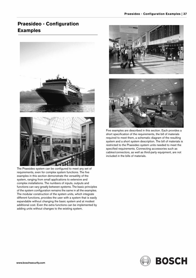
Praesideo - Configuration Examples | 37
www.boschsecurity.com
Praesideo - Configuration Examples
The Praesideo system can be configured to meet any set of requirements, even for complex system functions. The five examples in this section demonstrate the versatility of the system, ranging from small applications to extensive and complex installations. The numbers of inputs, outputs and functions can vary greatly between systems. The basic principles of the system configuration remains the same in all the examples. The modular construction of the system units, which integrate different functions, provides the user with a system that is easily expandable without changing the basic system and at modest additional cost. Even the extra functions can be implemented by adding units without changes to the existing system.
Five examples are described in this section. Each provides a short specification of the requirements, the bill of materials required to meet them, a schematic diagram of the resulting system and a short system description. The bill of materials is restricted to the Praesideo system units needed to meet the specified requirements. Connecting accessories such as cables/connectors, as well as third-party equipment, are not included in the bills of materials.
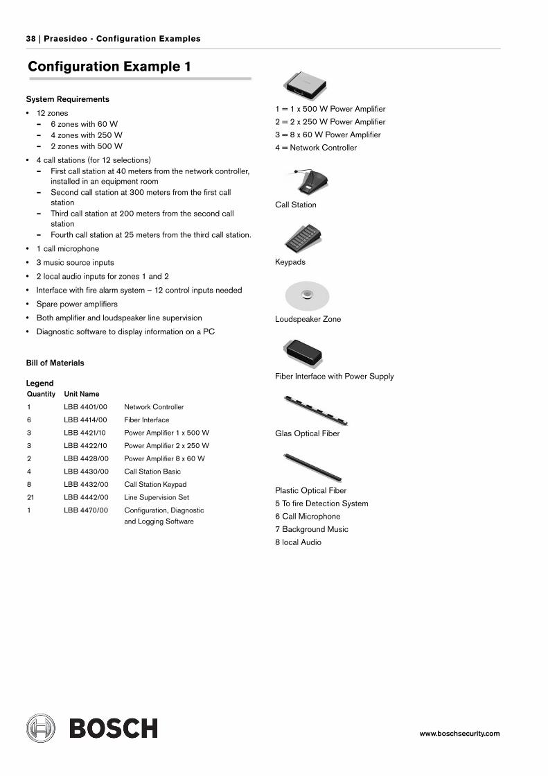
38 | Praesideo - Configuration Examples
www.boschsecurity.com
Configuration Example 1
System Requirements
• 12 zones– 6 zones with 60 W– 4 zones with 250 W– 2 zones with 500 W
• 4 call stations (for 12 selections)– First call station at 40 meters from the network controller,
installed in an equipment room– Second call station at 300 meters from the first call
station– Third call station at 200 meters from the second call
station– Fourth call station at 25 meters from the third call station.
• 1 call microphone
• 3 music source inputs
• 2 local audio inputs for zones 1 and 2
• Interface with fire alarm system – 12 control inputs needed
• Spare power amplifiers
• Both amplifier and loudspeaker line supervision
• Diagnostic software to display information on a PC
Bill of Materials
Legend
1 = 1 x 500 W Power Amplifier
2 = 2 x 250 W Power Amplifier
3 = 8 x 60 W Power Amplifier
4 = Network Controller
Call Station
Keypads
Loudspeaker Zone
Fiber Interface with Power Supply
Glas Optical Fiber
Plastic Optical Fiber
5 To fire Detection System
6 Call Microphone
7 Background Music
8 local Audio
Quantity Unit Name
1 LBB 4401/00 Network Controller
6 LBB 4414/00 Fiber Interface
3 LBB 4421/10 Power Amplifier 1 x 500 W
3 LBB 4422/10 Power Amplifier 2 x 250 W
2 LBB 4428/00 Power Amplifier 8 x 60 W
4 LBB 4430/00 Call Station Basic
8 LBB 4432/00 Call Station Keypad
21 LBB 4442/00 Line Supervision Set
1 LBB 4470/00 Configuration, Diagnostic
and Logging Software
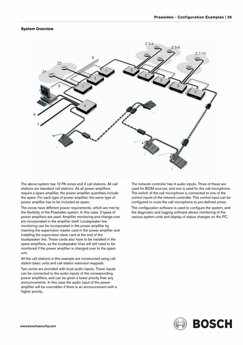
Praesideo - Configuration Examples | 39
www.boschsecurity.com
System Overview
The above system has 12 PA zones and 4 call stations. All call stations are standard call stations. As all power amplifiers require a spare amplifier, the power amplifier quantities include the spare. For each type of power amplifier, the same type of power amplifier has to be included as spare.
The zones have different power requirements, which are met by the flexibility of the Praesideo system. In this case, 3 types of power amplifiers are used. Amplifier monitoring and change-over are incorporated in the amplifier itself. Loudspeaker line monitoring can be incorporated in the power amplifier by inserting the supervision master card in the power amplifier and installing the supervision slave card at the end of the loudspeaker line. These cards also have to be installed in the spare amplifiers, as the loudspeaker lines will still need to be monitored if the power amplifier is changed over to the spare unit.
All the call stations in this example are constructed using call station basic units and call station extension keypads.
Two zones are provided with local audio inputs. These inputs can be connected to the audio inputs of the corresponding power amplifiers, and can be given a lower priority than any announcements. In this case the audio input of the power amplifier will be overridden if there is an announcement with a higher priority.
The network controller has 4 audio inputs. Three of these are used for BGM sources, and one is used for the call microphone. The switch of the call microphone is connected to one of the control inputs of the network controller. This control input can be configured to route the call microphone to pre-defined zones.
The configuration software is used to configure the system, and the diagnostic and logging software allows monitoring of the various system units and display of status changes on the PC.
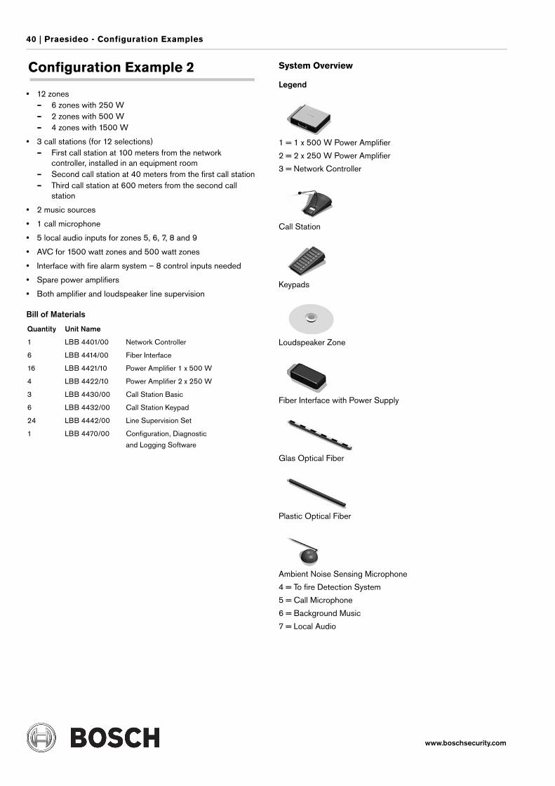
40 | Praesideo - Configuration Examples
www.boschsecurity.com
Configuration Example 2
• 12 zones– 6 zones with 250 W– 2 zones with 500 W– 4 zones with 1500 W
• 3 call stations (for 12 selections)– First call station at 100 meters from the network
controller, installed in an equipment room– Second call station at 40 meters from the first call station– Third call station at 600 meters from the second call
station
• 2 music sources
• 1 call microphone
• 5 local audio inputs for zones 5, 6, 7, 8 and 9
• AVC for 1500 watt zones and 500 watt zones
• Interface with fire alarm system – 8 control inputs needed
• Spare power amplifiers
• Both amplifier and loudspeaker line supervision
Bill of Materials
System Overview
Legend
1 = 1 x 500 W Power Amplifier
2 = 2 x 250 W Power Amplifier
3 = Network Controller
Call Station
Keypads
Loudspeaker Zone
Fiber Interface with Power Supply
Glas Optical Fiber
Plastic Optical Fiber
Ambient Noise Sensing Microphone
4 = To fire Detection System
5 = Call Microphone
6 = Background Music
7 = Local Audio
Quantity Unit Name
1 LBB 4401/00 Network Controller
6 LBB 4414/00 Fiber Interface
16 LBB 4421/10 Power Amplifier 1 x 500 W
4 LBB 4422/10 Power Amplifier 2 x 250 W
3 LBB 4430/00 Call Station Basic
6 LBB 4432/00 Call Station Keypad
24 LBB 4442/00 Line Supervision Set
1 LBB 4470/00 Configuration, Diagnostic
and Logging Software
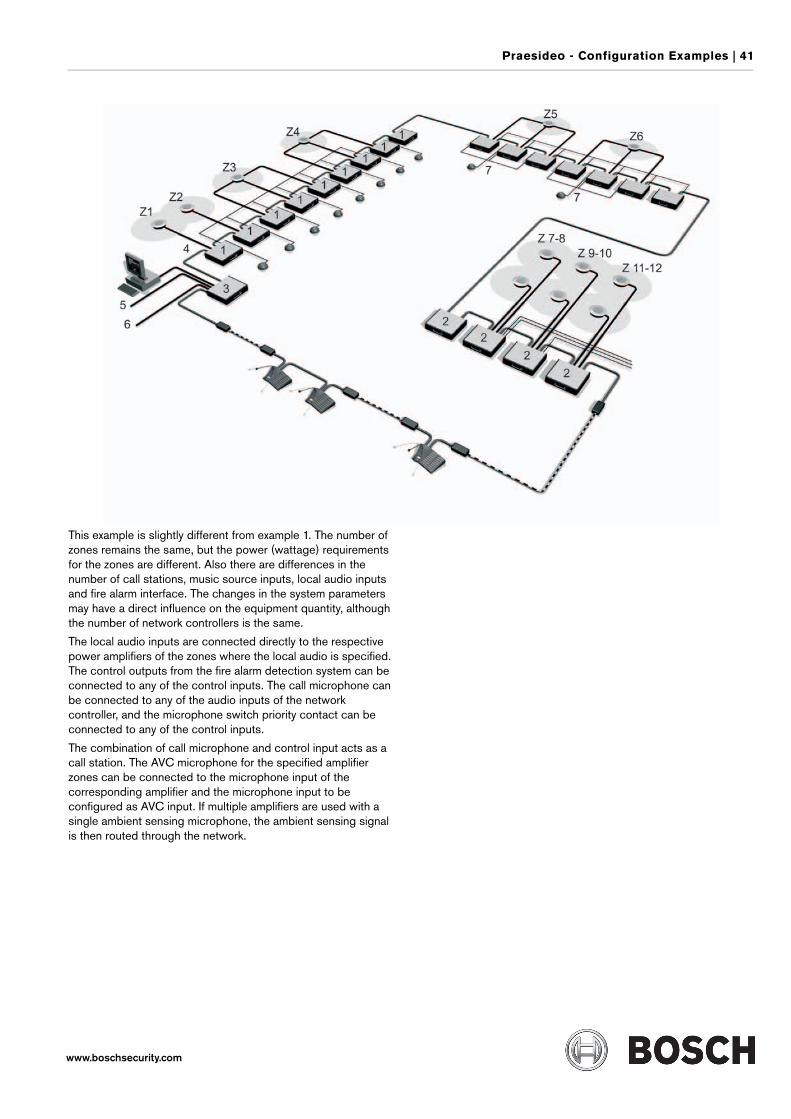
Praesideo - Configuration Examples | 41
www.boschsecurity.com
This example is slightly different from example 1. The number of zones remains the same, but the power (wattage) requirements for the zones are different. Also there are differences in the number of call stations, music source inputs, local audio inputs and fire alarm interface. The changes in the system parameters may have a direct influence on the equipment quantity, although the number of network controllers is the same.
The local audio inputs are connected directly to the respective power amplifiers of the zones where the local audio is specified. The control outputs from the fire alarm detection system can be connected to any of the control inputs. The call microphone can be connected to any of the audio inputs of the network controller, and the microphone switch priority contact can be connected to any of the control inputs.
The combination of call microphone and control input acts as a call station. The AVC microphone for the specified amplifier zones can be connected to the microphone input of the corresponding amplifier and the microphone input to be configured as AVC input. If multiple amplifiers are used with a single ambient sensing microphone, the ambient sensing signal is then routed through the network.
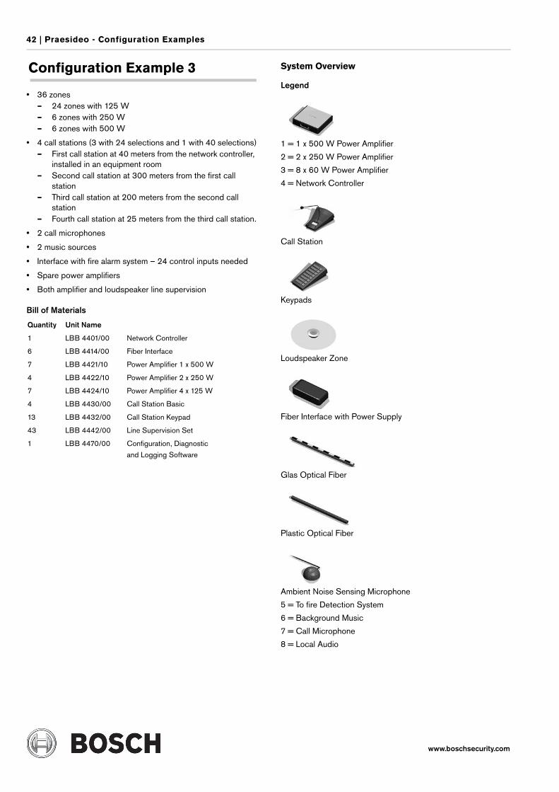
42 | Praesideo - Configuration Examples
www.boschsecurity.com
Configuration Example 3
• 36 zones– 24 zones with 125 W– 6 zones with 250 W– 6 zones with 500 W
• 4 call stations (3 with 24 selections and 1 with 40 selections)– First call station at 40 meters from the network controller,
installed in an equipment room– Second call station at 300 meters from the first call
station– Third call station at 200 meters from the second call
station– Fourth call station at 25 meters from the third call station.
• 2 call microphones
• 2 music sources
• Interface with fire alarm system – 24 control inputs needed
• Spare power amplifiers
• Both amplifier and loudspeaker line supervision
Bill of Materials
System Overview
Legend
1 = 1 x 500 W Power Amplifier
2 = 2 x 250 W Power Amplifier
3 = 8 x 60 W Power Amplifier
4 = Network Controller
Call Station
Keypads
Loudspeaker Zone
Fiber Interface with Power Supply
Glas Optical Fiber
Plastic Optical Fiber
Ambient Noise Sensing Microphone
5 = To fire Detection System
6 = Background Music
7 = Call Microphone
8 = Local Audio
Quantity Unit Name
1 LBB 4401/00 Network Controller
6 LBB 4414/00 Fiber Interface
7 LBB 4421/10 Power Amplifier 1 x 500 W
4 LBB 4422/10 Power Amplifier 2 x 250 W
7 LBB 4424/10 Power Amplifier 4 x 125 W
4 LBB 4430/00 Call Station Basic
13 LBB 4432/00 Call Station Keypad
43 LBB 4442/00 Line Supervision Set
1 LBB 4470/00 Configuration, Diagnostic
and Logging Software
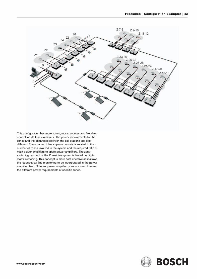
Praesideo - Configuration Examples | 43
www.boschsecurity.com
This configuration has more zones, music sources and fire alarm control inputs than example 2. The power requirements for the zones and the distances between the call stations are also different. The number of line supervisory sets is related to the number of zones involved in the system and the required ratio of main power amplifiers to spare power amplifiers. The zone-switching concept of the Praesideo system is based on digital matrix switching. This concept is more cost-effective as it allows the loudspeaker line monitoring to be incorporated in the power amplifier itself. Different power amplifier types are used to meet the different power requirements of specific zones.
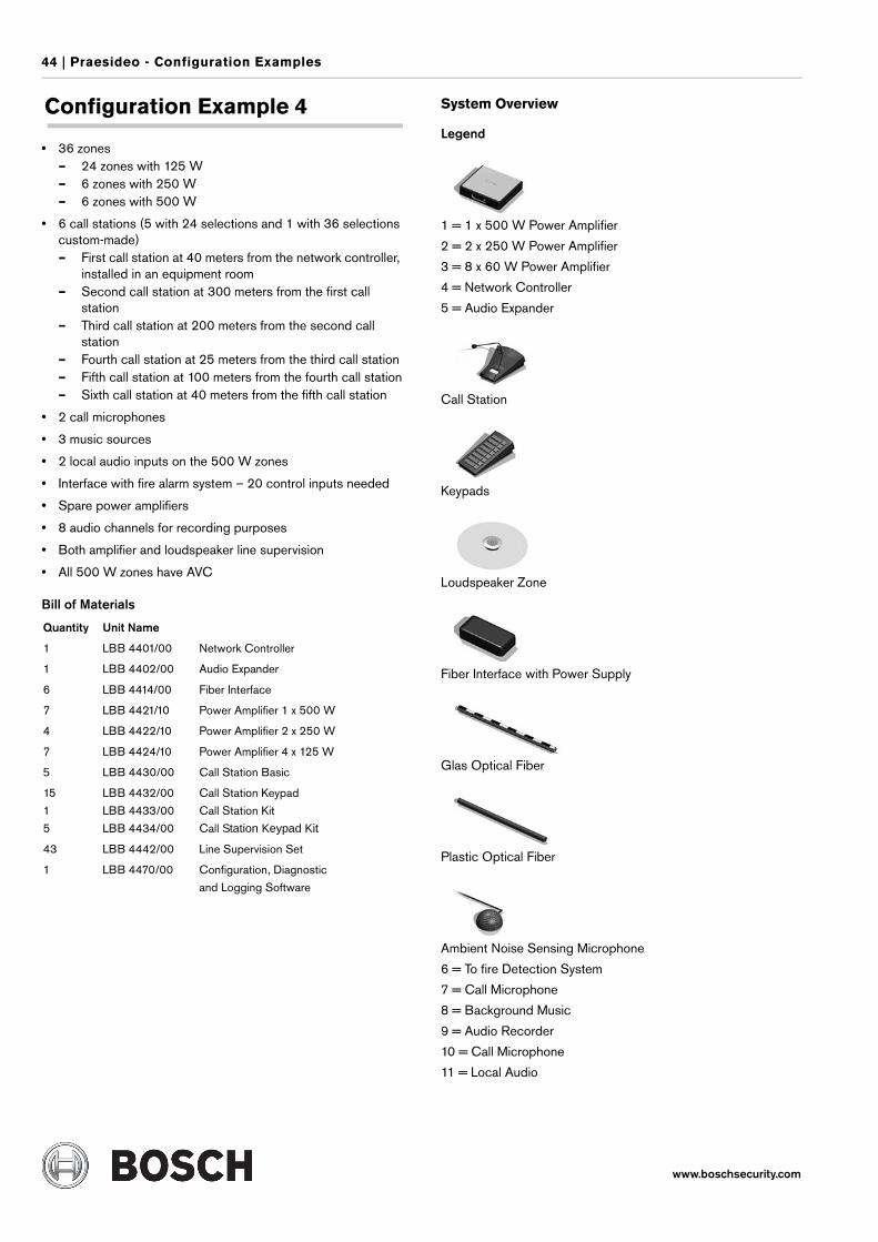
44 | Praesideo - Configuration Examples
www.boschsecurity.com
Configuration Example 4
• 36 zones– 24 zones with 125 W– 6 zones with 250 W– 6 zones with 500 W
• 6 call stations (5 with 24 selections and 1 with 36 selections custom-made)– First call station at 40 meters from the network controller,
installed in an equipment room– Second call station at 300 meters from the first call
station– Third call station at 200 meters from the second call
station– Fourth call station at 25 meters from the third call station– Fifth call station at 100 meters from the fourth call station– Sixth call station at 40 meters from the fifth call station
• 2 call microphones
• 3 music sources
• 2 local audio inputs on the 500 W zones
• Interface with fire alarm system – 20 control inputs needed
• Spare power amplifiers
• 8 audio channels for recording purposes
• Both amplifier and loudspeaker line supervision
• All 500 W zones have AVC
Bill of Materials
System Overview
Legend
1 = 1 x 500 W Power Amplifier
2 = 2 x 250 W Power Amplifier
3 = 8 x 60 W Power Amplifier
4 = Network Controller
5 = Audio Expander
Call Station
Keypads
Loudspeaker Zone
Fiber Interface with Power Supply
Glas Optical Fiber
Plastic Optical Fiber
Ambient Noise Sensing Microphone
6 = To fire Detection System
7 = Call Microphone
8 = Background Music
9 = Audio Recorder
10 = Call Microphone
11 = Local Audio
Quantity Unit Name
1 LBB 4401/00 Network Controller
1 LBB 4402/00 Audio Expander
6 LBB 4414/00 Fiber Interface
7 LBB 4421/10 Power Amplifier 1 x 500 W
4 LBB 4422/10 Power Amplifier 2 x 250 W
7 LBB 4424/10 Power Amplifier 4 x 125 W
5 LBB 4430/00 Call Station Basic
15
1
5
LBB 4432/00
LBB 4433/00
LBB 4434/00
Call Station Keypad
Call Station Kit
Call Station Keypad Kit
43 LBB 4442/00 Line Supervision Set
1 LBB 4470/00 Configuration, Diagnostic
and Logging Software
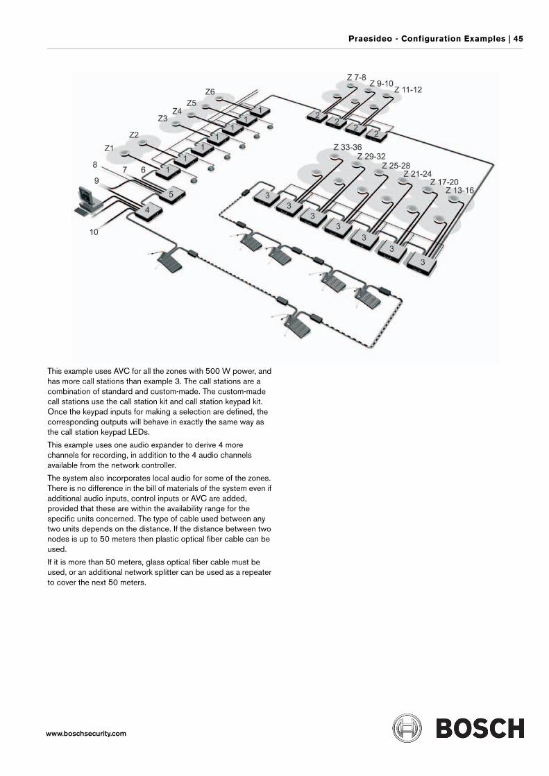
Praesideo - Configuration Examples | 45
www.boschsecurity.com
This example uses AVC for all the zones with 500 W power, and has more call stations than example 3. The call stations are a combination of standard and custom-made. The custom-made call stations use the call station kit and call station keypad kit. Once the keypad inputs for making a selection are defined, the corresponding outputs will behave in exactly the same way as the call station keypad LEDs.
This example uses one audio expander to derive 4 more channels for recording, in addition to the 4 audio channels available from the network controller.
The system also incorporates local audio for some of the zones. There is no difference in the bill of materials of the system even if additional audio inputs, control inputs or AVC are added, provided that these are within the availability range for the specific units concerned. The type of cable used between any two units depends on the distance. If the distance between two nodes is up to 50 meters then plastic optical fiber cable can be used.
If it is more than 50 meters, glass optical fiber cable must be used, or an additional network splitter can be used as a repeater to cover the next 50 meters.
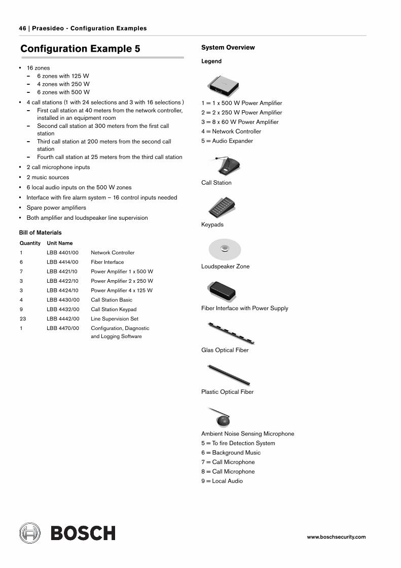
46 | Praesideo - Configuration Examples
www.boschsecurity.com
Configuration Example 5
• 16 zones– 6 zones with 125 W– 4 zones with 250 W– 6 zones with 500 W
• 4 call stations (1 with 24 selections and 3 with 16 selections )– First call station at 40 meters from the network controller,
installed in an equipment room– Second call station at 300 meters from the first call
station– Third call station at 200 meters from the second call
station– Fourth call station at 25 meters from the third call station
• 2 call microphone inputs
• 2 music sources
• 6 local audio inputs on the 500 W zones
• Interface with fire alarm system – 16 control inputs needed
• Spare power amplifiers
• Both amplifier and loudspeaker line supervision
Bill of Materials
System Overview
Legend
1 = 1 x 500 W Power Amplifier
2 = 2 x 250 W Power Amplifier
3 = 8 x 60 W Power Amplifier
4 = Network Controller
5 = Audio Expander
Call Station
Keypads
Loudspeaker Zone
Fiber Interface with Power Supply
Glas Optical Fiber
Plastic Optical Fiber
Ambient Noise Sensing Microphone
5 = To fire Detection System
6 = Background Music
7 = Call Microphone
8 = Call Microphone
9 = Local Audio
Quantity Unit Name
1 LBB 4401/00 Network Controller
6 LBB 4414/00 Fiber Interface
7 LBB 4421/10 Power Amplifier 1 x 500 W
3 LBB 4422/10 Power Amplifier 2 x 250 W
3 LBB 4424/10 Power Amplifier 4 x 125 W
4 LBB 4430/00 Call Station Basic
9 LBB 4432/00 Call Station Keypad
23 LBB 4442/00 Line Supervision Set
1 LBB 4470/00 Configuration, Diagnostic
and Logging Software
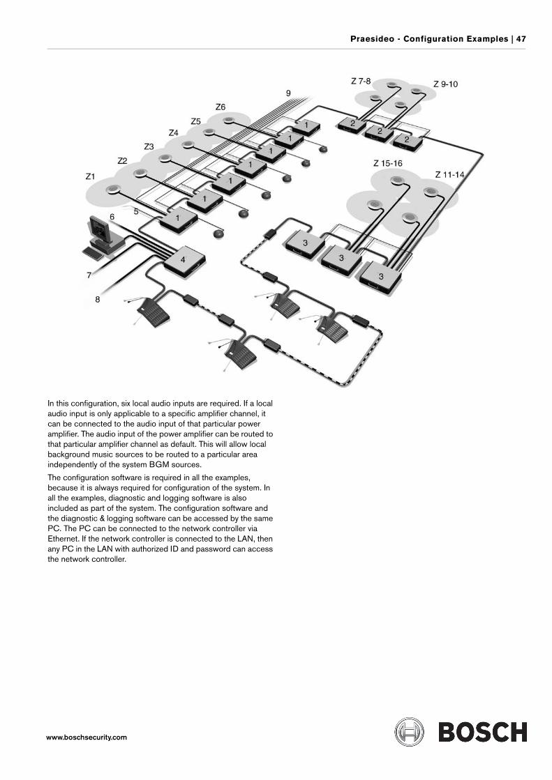
Praesideo - Configuration Examples | 47
www.boschsecurity.com
In this configuration, six local audio inputs are required. If a local audio input is only applicable to a specific amplifier channel, it can be connected to the audio input of that particular power amplifier. The audio input of the power amplifier can be routed to that particular amplifier channel as default. This will allow local background music sources to be routed to a particular area independently of the system BGM sources.
The configuration software is required in all the examples, because it is always required for configuration of the system. In all the examples, diagnostic and logging software is also included as part of the system. The configuration software and the diagnostic & logging software can be accessed by the same PC. The PC can be connected to the network controller via Ethernet. If the network controller is connected to the LAN, then any PC in the LAN with authorized ID and password can access the network controller.
48 | Praesideo - Digital Public Address and Emergency Sound System
www.boschsecurity.com
CConfiguration Example 1. . . . . . . . . . . . . . . . . . . . . . . . . 38Configuration Example 2. . . . . . . . . . . . . . . . . . . . . . . . . 40Configuration Example 3. . . . . . . . . . . . . . . . . . . . . . . . . 42Configuration Example 4. . . . . . . . . . . . . . . . . . . . . . . . . 44Configuration Example 5. . . . . . . . . . . . . . . . . . . . . . . . . 46
LLBB 4401/00 Network Controller . . . . . . . . . . . . . . . . . . . 5LBB 4402/00 Audio Expander . . . . . . . . . . . . . . . . . . . . . 8LBB 4404/00 CobraNet Interface . . . . . . . . . . . . . . . . . . 10LBB 4410/00 Network Splitter . . . . . . . . . . . . . . . . . . . . 24LBB 4414/00 Fiber Interface . . . . . . . . . . . . . . . . . . . . . 25LBB 4416/xx Network Cables . . . . . . . . . . . . . . . . . . . . . 26LBB 4417/00 Set Network Connectors . . . . . . . . . . . . . . 26LBB 4418/00 Cable Connector Tool Kit . . . . . . . . . . . . . . 26LBB 4419/00 Cable Couplers (10 pcs) . . . . . . . . . . . . . . 27LBB 442x/x0 Power Amplifiers . . . . . . . . . . . . . . . . . . . . 13LBB 4430/00 Call Station Basic . . . . . . . . . . . . . . . . . . . 16LBB 4432/00 Call Station Keypad. . . . . . . . . . . . . . . . . . 18LBB 4433/00 Call Station Kit . . . . . . . . . . . . . . . . . . . . . 20LBB 4434/00 Call Station Keypad Kit . . . . . . . . . . . . . . . 21LBB 4436/00 Button Cover . . . . . . . . . . . . . . . . . . . . . . 27LBB 4437/00 Call Station Interface . . . . . . . . . . . . . . . . . 22LBB 4438/00 Call Station Remote . . . . . . . . . . . . . . . . . 23LBB 4440/00 Supervision Control Board . . . . . . . . . . . . . 28LBB 4441/00 Loudspeaker Supervision Board . . . . . . . . . 30LBB 4442/00 Line Supervision Set . . . . . . . . . . . . . . . . . 32LBB 4443/00 End of Line (EOL) Supervision Board . . . . . . 33LBB 4470/00 Configuration, Diagnostic and Logging Software 34
PPraesideo - Configuration Examples . . . . . . . . . . . . . . . . . 37Praesideo - Digital Public Address and Emergency Sound Sys-tem . . . . . . . . . . . . . . . . . . . . . . . . . . . . . . . . . . . . . . . . 2