bos photoelectric sensors for special applications - …€¦ · photoelectric sensors for special...
TRANSCRIPT
Photo
ele
ctri
c Senso
rsfo
r Speci
al A
pplic
atio
ns
2.2.1
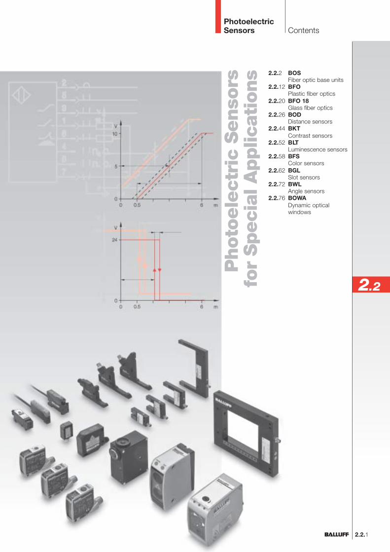
2.2.2 BOSFiber optic base units
2.2.12 BFOPlastic fiber optics
2.2.20 BFO 18Glass fiber optics
2.2.26 BODDistance sensors
2.2.44 BKTContrast sensors
2.2.52 BLTLuminescence sensors
2.2.58 BFSColor sensors
2.2.62 BGLSlot sensors
2.2.72 BWLAngle sensors
2.2.76 BOWADynamic opticalwindows
Contents
2.2
PhotoelectricSensors
PhotoelectricSensors
BOSFiber Optic Base Units
2.2.2
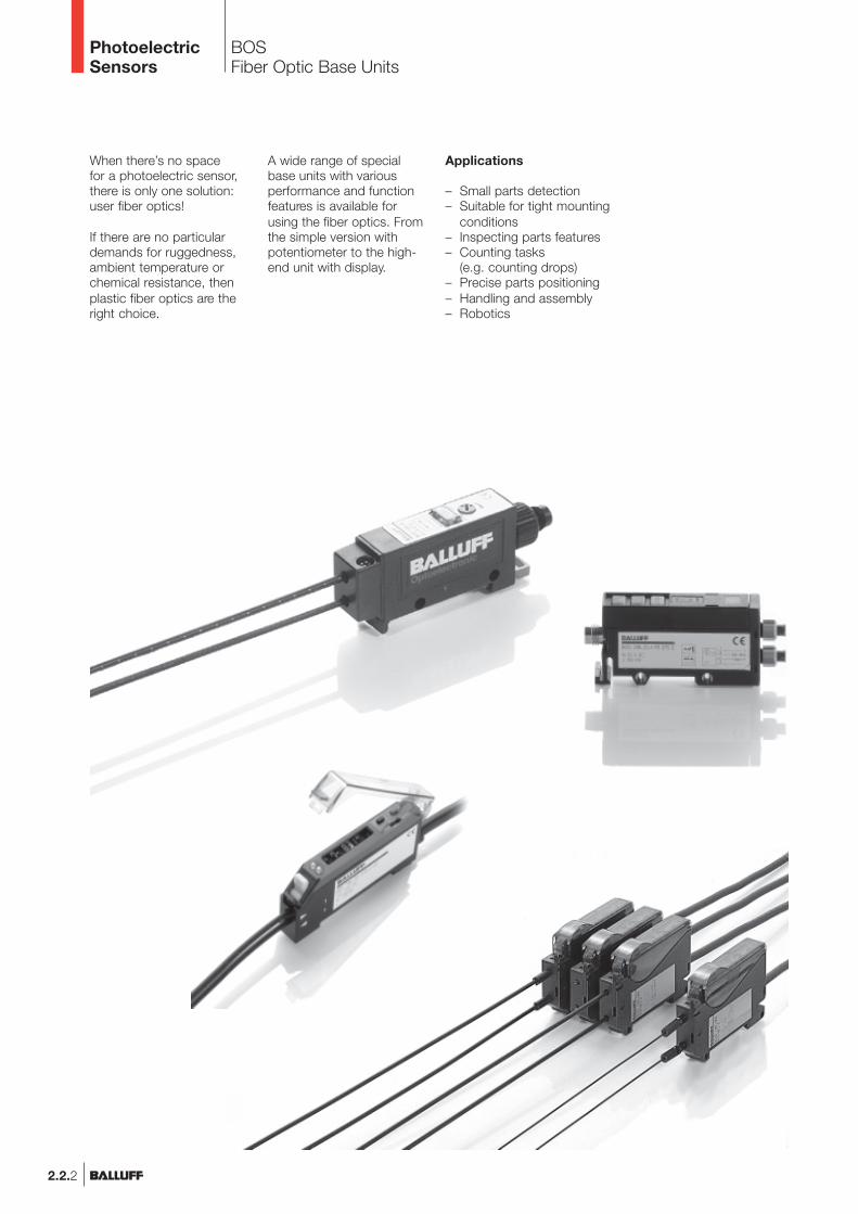
When there’s no spacefor a photoelectric sensor,there is only one solution:user fiber optics!
If there are no particulardemands for ruggedness,ambient temperature orchemical resistance, thenplastic fiber optics are theright choice.
A wide range of specialbase units with variousperformance and functionfeatures is available forusing the fiber optics. Fromthe simple version withpotentiometer to the high-end unit with display.
Applications
– Small parts detection– Suitable for tight mounting
conditions– Inspecting parts features– Counting tasks
(e.g. counting drops)– Precise parts positioning– Handling and assembly– Robotics
BOSFiber Optic Base UnitsProduct overview
2.2.3
2.2
Connectorspage 6.2 ...
2.3
6
PhotoelectricSensors
Photoelectricsensorsaccessoriespage 2.3.2 ...
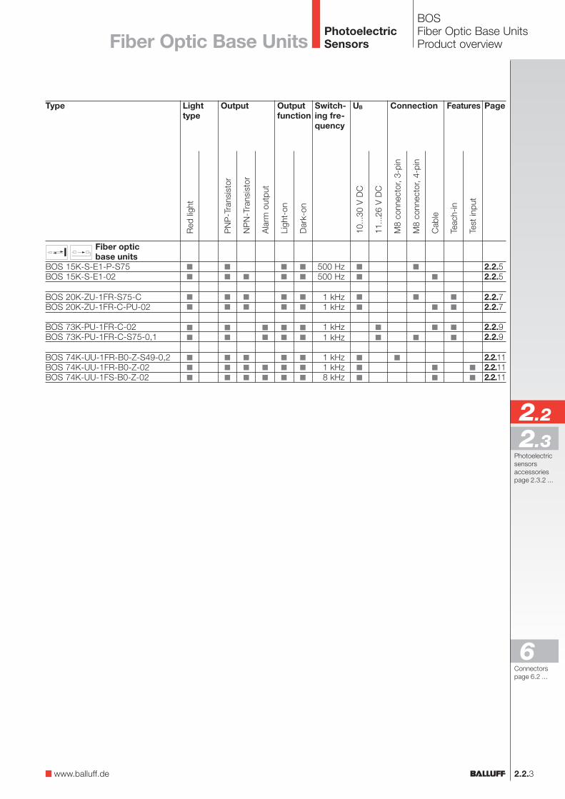
Type
Fiber opticbase units
BOS 15K-S-E1-P-S75BOS 15K-S-E1-02
BOS 20K-ZU-1FR-S75-CBOS 20K-ZU-1FR-C-PU-02
BOS 73K-PU-1FR-C-02BOS 73K-PU-1FR-C-S75-0,1
BOS 74K-UU-1FR-B0-Z-S49-0,2BOS 74K-UU-1FR-B0-Z-02BOS 74K-UU-1FS-B0-Z-02
OutputLighttype
Connection
500 Hz500 Hz
1 kHz1 kHz
1 kHz1 kHz
1 kHz1 kHz8 kHz
Outputfunction
Page
2.2.52.2.5
2.2.72.2.7
2.2.92.2.9
2.2.112.2.112.2.11
Features
Red
ligh
t
M8
conn
ecto
r, 3-
pin
Cab
le
10...
30 V
DC
Teac
h-in
NP
N-T
rans
isto
r
PN
P-T
rans
isto
r
Ligh
t-on
Dar
k-on
UBSwitch-ing fre-quency
Ala
rm o
utpu
t
11...
26 V
DC
M8
conn
ecto
r, 4-
pin
Test
inpu
t
Fiber Optic Base Units
www.balluff.de

PhotoelectricSensors
BOS 15KFiber Optic Base Units
2.2.4
For standard applications,choose the BOS 15K. Itsmain features are cost-effectiveness and ease ofhandling.
Features
– Sensitivity setting with a270° potentiometer
– Contamination indicator– PNP/NPN wiring
(cable version)
Recommended accessoriesplease order separately
ConnectorBKS-S 74/BKS-S 75
Mounting notes for fiber optics
The resistance of the sealing ring must be overcomewhen connecting the fiber optics to the base unit.
Mounting bracket(included)
Wiring diagrams
NONC
NONC
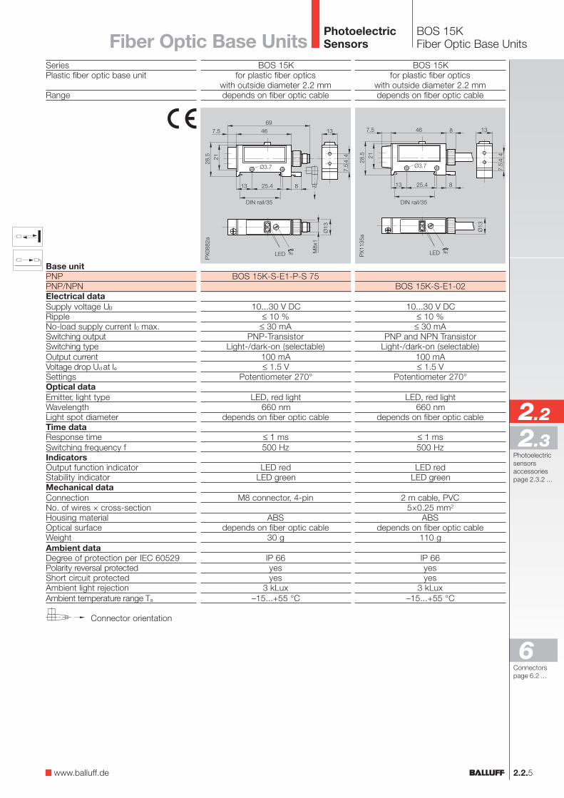
SeriesPlastic fiber optic base unit
Range
Base unitPNPPNP/NPNElectrical dataSupply voltage UB
RippleNo-load supply current I0 max.Switching outputSwitching typeOutput currentVoltage drop Ud at IeSettingsOptical dataEmitter, light typeWavelengthLight spot diameterTime dataResponse timeSwitching frequency fIndicatorsOutput function indicatorStability indicatorMechanical dataConnectionNo. of wires × cross-sectionHousing materialOptical surfaceWeightAmbient dataDegree of protection per IEC 60529Polarity reversal protectedShort circuit protectedAmbient light rejectionAmbient temperature range Ta
BOS 15Kfor plastic fiber optics
with outside diameter 2.2 mmdepends on fiber optic cable
BOS 15K-S-E1-02
10...30 V DC≤ 10 %
≤ 30 mAPNP and NPN Transistor
Light-/dark-on (selectable)100 mA≤ 1.5 V
Potentiometer 270°
LED, red light660 nm
depends on fiber optic cable
≤ 1 ms500 Hz
LED redLED green
2 m cable, PVC5×0.25 mm2
ABSdepends on fiber optic cable
110 g
IP 66yesyes
3 kLux–15...+55 °C
BOS 15Kfor plastic fiber optics
with outside diameter 2.2 mmdepends on fiber optic cable
BOS 15K-S-E1-P-S 75
10...30 V DC≤ 10 %
≤ 30 mAPNP-Transistor
Light-/dark-on (selectable)100 mA≤ 1.5 V
Potentiometer 270°
LED, red light660 nm
depends on fiber optic cable
≤ 1 ms500 Hz
LED redLED green
M8 connector, 4-pin
ABSdepends on fiber optic cable
30 g
IP 66yesyes
3 kLux–15...+55 °C
DIN Schiene /35
DIN Schiene /35
Connector orientation
DIN rail/35 DIN rail/35
2.2.5
BOS 15KFiber Optic Base Units
2.2
2.3
6
PhotoelectricSensorsFiber Optic Base Units
www.balluff.de
Connectorspage 6.2 ...
Photoelectricsensorsaccessoriespage 2.3.2 ...
BOS 20KFiber Optic Base Units
2.2.6
PhotoelectricSensors
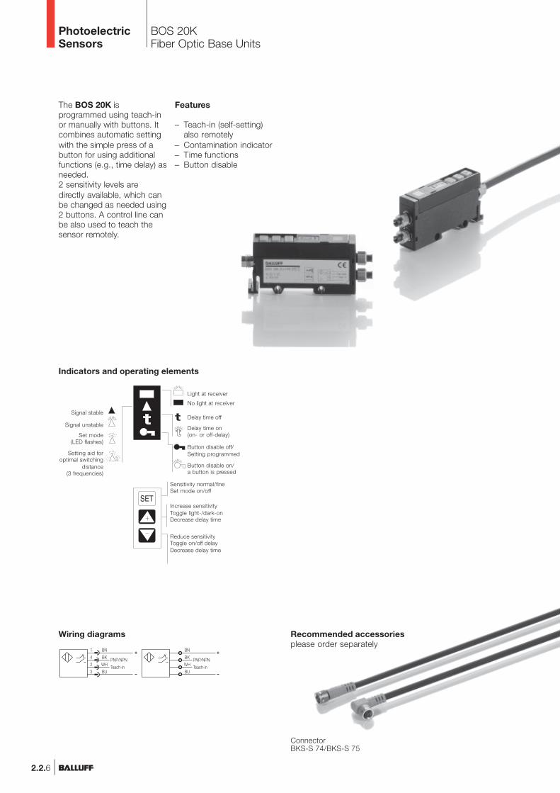
The BOS 20K isprogrammed using teach-inor manually with buttons. Itcombines automatic settingwith the simple press of abutton for using additionalfunctions (e.g., time delay) asneeded.2 sensitivity levels aredirectly available, which canbe changed as needed using2 buttons. A control line canbe also used to teach thesensor remotely.
Features
– Teach-in (self-setting)also remotely
– Contamination indicator– Time functions– Button disable
Recommended accessoriesplease order separately
ConnectorBKS-S 74/BKS-S 75
Indicators and operating elements
Reduce sensitivityToggle on/off delayDecrease delay time
Increase sensitivityToggle light-/dark-onDecrease delay time
Sensitivity normal/fineSet mode on/off
Button disable off/Setting programmed
Button disable on/a button is pressed
Delay time on(on- or off-delay)
Delay time off
Light at receiver
Set mode(LED flashes)
Signal unstable
Signal stable
Setting aid foroptimal switching
distance(3 frequencies)
No light at receiver
Wiring diagrams
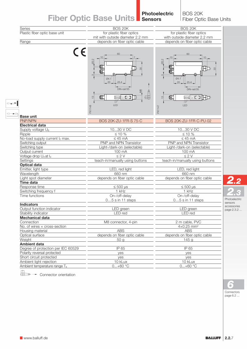
BOS 20Kfor plastic fiber optics
mit with outside diameter 2.2 mmdepends on fiber optic cable
BOS 20K-ZU-1FR-S 75-C
10...30 V DC≤ 10 %
≤ 45 mAPNP and NPN Transistor
Light-/dark-on (selectable)100 mA
≤ 2 Vteach-in/manually using buttons
LED, red light660 nm
depends on fiber optic cable
≤ 500 µs1 kHz
On-/off-delay0…5 s in 11 steps
LED greenLED red
M8 connector, 4-pin
ABSdepends on fiber optic cable
50 g
IP 65yesyes
10 kLux0...+60 °C
BOS 20Kfor plastic fiber optics
with outside diameter 2.2 mmdepends on fiber optic cable
BOS 20K-ZU-1FR-C-PU-02
10...30 V DC≤ 10 %
≤ 45 mAPNP and NPN Transistor
Light-/dark-on (selectable)100 mA
≤ 2 Vteach-in/manually using buttons
LED, red light660 nm
depends on fiber optic cable
≤ 500 µs1 kHz
On-/off-delay0…5 s in 11 steps
LED greenLED red
2 m cable, PVC4×0.25 mm2
ABSdepends on fiber optic cable
145 g
IP 65yesyes
10 kLux0...+60 °C
2.2.7
BOS 20KFiber Optic Base Units
DIN-rail/35 DIN-rail/35
2.2
2.3
6
PhotoelectricSensors
SeriesPlastic fiber optic base unit
Range
Base unitPNP/NPNElectrical dataSupply voltage UB
RippleNo-load supply current I0 max.Switching outputSwitching typeOutput currentVoltage drop Ud at IeSettingsOptical dataEmitter, light typeWavelengthLight spot diameterTime dataResponse timeSwitching frequency fTime functions
IndicatorsOutput function indicatorStability indicatorMechanical dataConnectionNo. of wires × cross-sectionHousing materialOptical surfaceWeightAmbient dataDegree of protection per IEC 60529Polarity reversal protectedShort circuit protectedAmbient light rejectionAmbient temperature range Ta
Connector orientation
Fiber Optic Base Units
www.balluff.de
Connectorspage 6.2 ...
Photoelectricsensorsaccessoriespage 2.3.2 ...
BOS 73KFiber Optic Base Units
2.2.8
PhotoelectricSensors
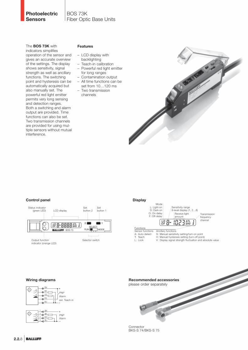
The BOS 73K withindicators simplifiesoperation of the sensor andgives an accurate overviewof the settings. The displayshows sensitivity, signalstrength as well as ancillaryfunctions. The switchingpoint and hysteresis can beautomatically acquired butalso manually set. Thepowerful red light emitterpermits very long sensingand detection ranges.Both a switching and alarmoutput are provided. Timefunctions can also be set.Two transmission channelsare provided for using mul-tiple sensors without mutualinterference.
Features
– LCD display withbacklighting
– Teach-in calibration– Powerful red light emitter
for long ranges– Contamination output– All time functions can be
set from 10…120 ms– Two transmission
channels
Recommended accessoriesplease order separately
ConnectorBKS-S 74/BKS-S 75
Control panel
Wiring diagrams
ModeL: Light-onD: Dark-on
O: On-delayF: Off-delay
Display
Sensitivity range8-level display (1, 2…8)
Receive lightamount
Transmissionfrequencychannel
FunctionsSensor functions Ancillary functionsA: Auto-detect S: Manual sensitivity setting/turn-on pointT: Teach H: Manual hysteresis setting (turn-off point)L: Lock V: Display signal strength fluctuation and absolute value
Status indicator(green LED) LCD display
Setbutton 2
Setbutton 1
Output functionindicator (orange LED)
Selector switch
PNPAlarm
ext. Teach-in
AlarmPNP
2.2.9
BOS 73KFiber Optic Base Units
2.2
2.3
6
PhotoelectricSensors
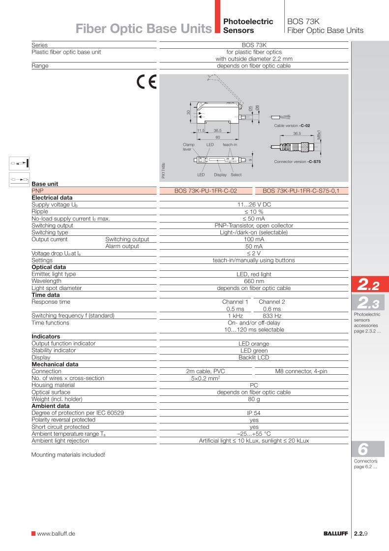
BOS 73Kfor plastic fiber optics
with outside diameter 2.2 mmdepends on fiber optic cable
SeriesPlastic fiber optic base unit
Range
Base unitPNPElectrical dataSupply voltage UB
RippleNo-load supply current I0 max.Switching outputSwitching typeOutput current Switching output
Alarm outputVoltage drop Ud at IeSettingsOptical dataEmitter, light typeWavelengthLight spot diameterTime dataResponse time
Switching frequency f (standard)Time functions
IndicatorsOutput function indicatorStability indicatorDisplayMechanical dataConnectionNo. of wires × cross-sectionHousing materialOptical surfaceWeight (incl. holder)Ambient dataDegree of protection per IEC 60529Polarity reversal protectedShort circuit protectedAmbient temperature range Ta
Ambient light rejection
BOS 73K-PU-1FR-C-02 BOS 73K-PU-1FR-C-S75-0,1
11...26 V DC≤ 10 %
≤ 50 mAPNP-Transistor, open collector
Light-/dark-on (selectable)100 mA50 mA≤ 2 V
teach-in/manually using buttons
LED, red light660 nm
depends on fiber optic cable
Channel 1 Channel 20.5 ms 0.6 ms1 kHz 833 HzOn- and/or off-delay
10…120 ms selectable
LED orangeLED green
Backlit LCD
2m cable, PVC M8 connector, 4-pin5×0.2 mm2
PCdepends on fiber optic cable
80 g
IP 54yesyes
–25...+55 °CArtificial light ≤ 10 kLux, sunlight ≤ 20 kLux
Mounting materials included!
Display Select
Clamplever
teach-inLED
LED
Connector version -C-S75
Cable version -C-02
Fiber Optic Base Units
www.balluff.de
Connectorspage 6.2 ...
Photoelectricsensorsaccessoriespage 2.3.2 ...
BOS 74KFiber Optic Base Units
2.2.10
PhotoelectricSensors
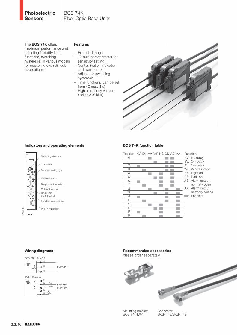
The BOS 74K offersmaximum performance andadjusting flexibility (timefunctions, switchinghysteresis) in various modelsfor mastering even difficultapplications.
Features
– Extended range– 12-turn potentiometer for
sensitivity setting– Contamination indicator
and alarm output– Adjustable switching
hysteresis– Time functions (can be set
from 40 ms…1 s)– High-frequency version
available (8 kHz)
Recommended accessoriesplease order separately
ConnectorBKS-_ 48/BKS-_ 49
Mounting bracketBOS 74-HW-1
Indicators and operating elements
Switching distance
Hysteresis
Receiver seeing light
Calibration aid
Response time select
Output function
Delay time(40 ms…1 s)
Function and time set
PNP/NPN switch
Position KV EV AV WF HS DS AE AA0123456789ABCDEF
FunctionKV: No delayEV: On-delayAV: Off-delayWF: Wipe functionHS: Light-onDS: Dark-onAE: Alarm output
normally openAA: Alarm output
normally closed: Enabled
BOS 74K function table
Wiring diagrams
+
–
PNP/NPN
+
–
PNP/NPNPNP/NPN
BOS 74K...Z-02
BOS 74K...S49-0,2
BOS 74KFiber Optic Base Units
2.2.11
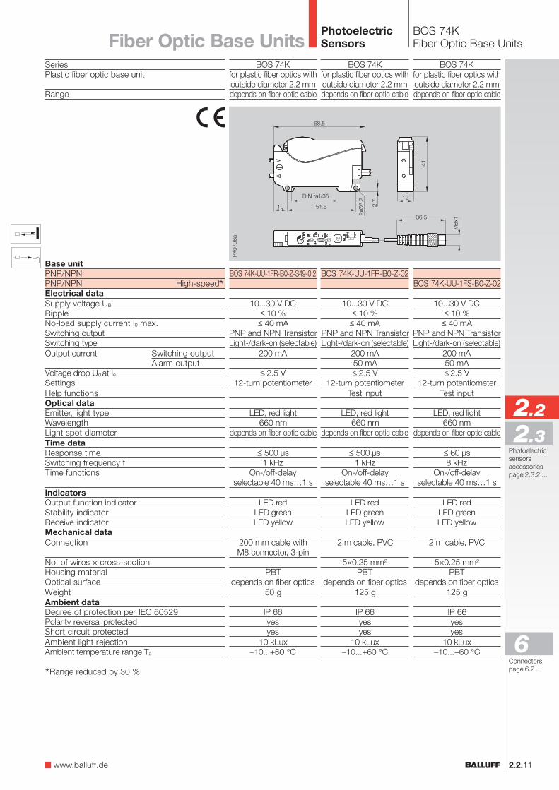
SeriesPlastic fiber optic base unit
Range
Base unitPNP/NPNPNP/NPN High-speed*Electrical dataSupply voltage UB
RippleNo-load supply current I0 max.Switching outputSwitching typeOutput current Switching output
Alarm outputVoltage drop Ud at IeSettingsHelp functionsOptical dataEmitter, light typeWavelengthLight spot diameterTime dataResponse timeSwitching frequency fTime functions
IndicatorsOutput function indicatorStability indicatorReceive indicatorMechanical dataConnection
No. of wires × cross-sectionHousing materialOptical surfaceWeightAmbient dataDegree of protection per IEC 60529Polarity reversal protectedShort circuit protectedAmbient light rejectionAmbient temperature range Ta
*Range reduced by 30 %
BOS 74Kfor plastic fiber optics withoutside diameter 2.2 mmdepends on fiber optic cable
BOS 74K-UU-1FR-B0-Z-S49-0,2
10...30 V DC≤ 10 %
≤ 40 mAPNP and NPN TransistorLight-/dark-on (selectable)
200 mA
≤ 2.5 V12-turn potentiometer
LED, red light660 nm
depends on fiber optic cable
≤ 500 µs1 kHz
On-/off-delayselectable 40 ms…1 s
LED redLED greenLED yellow
200 mm cable withM8 connector, 3-pin
PBTdepends on fiber optics
50 g
IP 66yesyes
10 kLux–10...+60 °C
2.2
2.3
6
PhotoelectricSensorsFiber Optic Base Units
BOS 74Kfor plastic fiber optics withoutside diameter 2.2 mmdepends on fiber optic cable
BOS 74K-UU-1FR-B0-Z-02
10...30 V DC≤ 10 %
≤ 40 mAPNP and NPN TransistorLight-/dark-on (selectable)
200 mA50 mA≤ 2.5 V
12-turn potentiometerTest input
LED, red light660 nm
depends on fiber optic cable
≤ 500 µs1 kHz
On-/off-delayselectable 40 ms…1 s
LED redLED greenLED yellow
2 m cable, PVC
5×0.25 mm2
PBTdepends on fiber optics
125 g
IP 66yesyes
10 kLux–10...+60 °C
BOS 74Kfor plastic fiber optics withoutside diameter 2.2 mmdepends on fiber optic cable
BOS 74K-UU-1FS-B0-Z-02
10...30 V DC≤ 10 %
≤ 40 mAPNP and NPN TransistorLight-/dark-on (selectable)
200 mA50 mA≤ 2.5 V
12-turn potentiometerTest input
LED, red light660 nm
depends on fiber optic cable
≤ 60 µs8 kHz
On-/off-delayselectable 40 ms…1 s
LED redLED greenLED yellow
2 m cable, PVC
5×0.25 mm2
PBTdepends on fiber optics
125 g
IP 66yesyes
10 kLux–10...+60 °C
www.balluff.de
Connectorspage 6.2 ...
Photoelectricsensorsaccessoriespage 2.3.2 ...
DIN rail/35
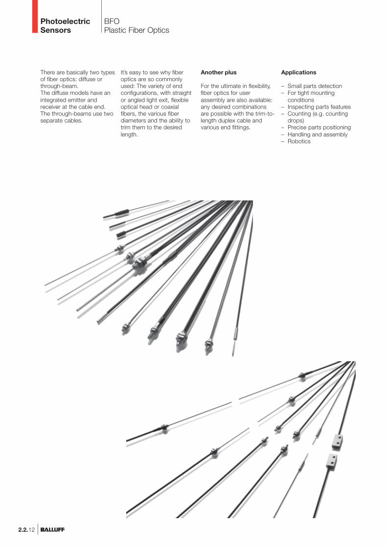
There are basically two typesof fiber optics: diffuse orthrough-beam.The diffuse models have anintegrated emitter andreceiver at the cable end.The through-beams use twoseparate cables.
2.2.12
BFOPlastic Fiber Optics
PhotoelectricSensors
Another plus
For the ultimate in flexibility,fiber optics for userassembly are also available:any desired combinationsare possible with the trim-to-length duplex cable andvarious end fittings.
It’s easy to see why fiberoptics are so commonlyused: The variety of endconfigurations, with straightor angled light exit, flexibleoptical head or coaxialfibers, the various fiberdiameters and the ability totrim them to the desiredlength.
Applications
– Small parts detection– For tight mounting
conditions– Inspecting parts features– Counting (e.g. counting
drops)– Precise parts positioning– Handling and assembly– Robotics
2.2.13
BFOPlastic Fiber OpticsProduct overview
2.2
2.3
6
PhotoelectricSensors
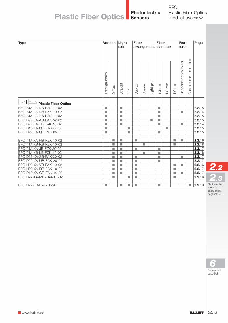
Type
Plastic Fiber OpticsBFO 74A-LA-KB-PZK-10-02BFO 74A-LA-NB-PZK-10-02BFO 74A-LA-RB-PZK-10-02BFO D22-LA-AD-EAK-52-02BFO D22-LA-TB-EAK-10-02BFO D13-LA-QB-EAK-05-02BFO D22-LA-QB-PAK-05-02
BFO 74A-XA-HB-PZK-10-02BFO 74A-XB-KB-PZK-10-02BFO 74A-XA-JB-PZK-20-02BFO 74A-XB-LB-PZK-15-02BFO D22-XA-SB-EAK-20-02BFO D22-XA-UB-EAK-20-02BFO N22-XA-VB-EAK-10-02BFO N22-XA-RB-EAK-10-02BFO D10-XA-GB-EAK-10-02BFO D22-XA-MB-PAK-10-02
BFO D22-LD-EAK-10-20
Fiberarrangement
Lightexit
Fiberdiameter
Page
2.2.152.2.142.2.152.2.152.2.142.2.152.2.15
2.2.162.2.182.2.172.2.182.2.172.2.172.2.162.2.172.2.172.2.18
2.2.19
Str
aigh
t
90°
2.2
mm
1.3
mm
Coa
xial
Dup
lex
Can
be
user
-ass
embl
ed
Ligh
t gr
id
Version
Thro
ugh-
beam
Diff
use
Fea-tures
Ben
dabl
e op
tical
hea
d
1.0
mm
Plastic Fiber Optics
www.balluff.de
Connectorspage 6.2 ...
Photoelectricsensorsaccessoriespage 2.3.2 ...
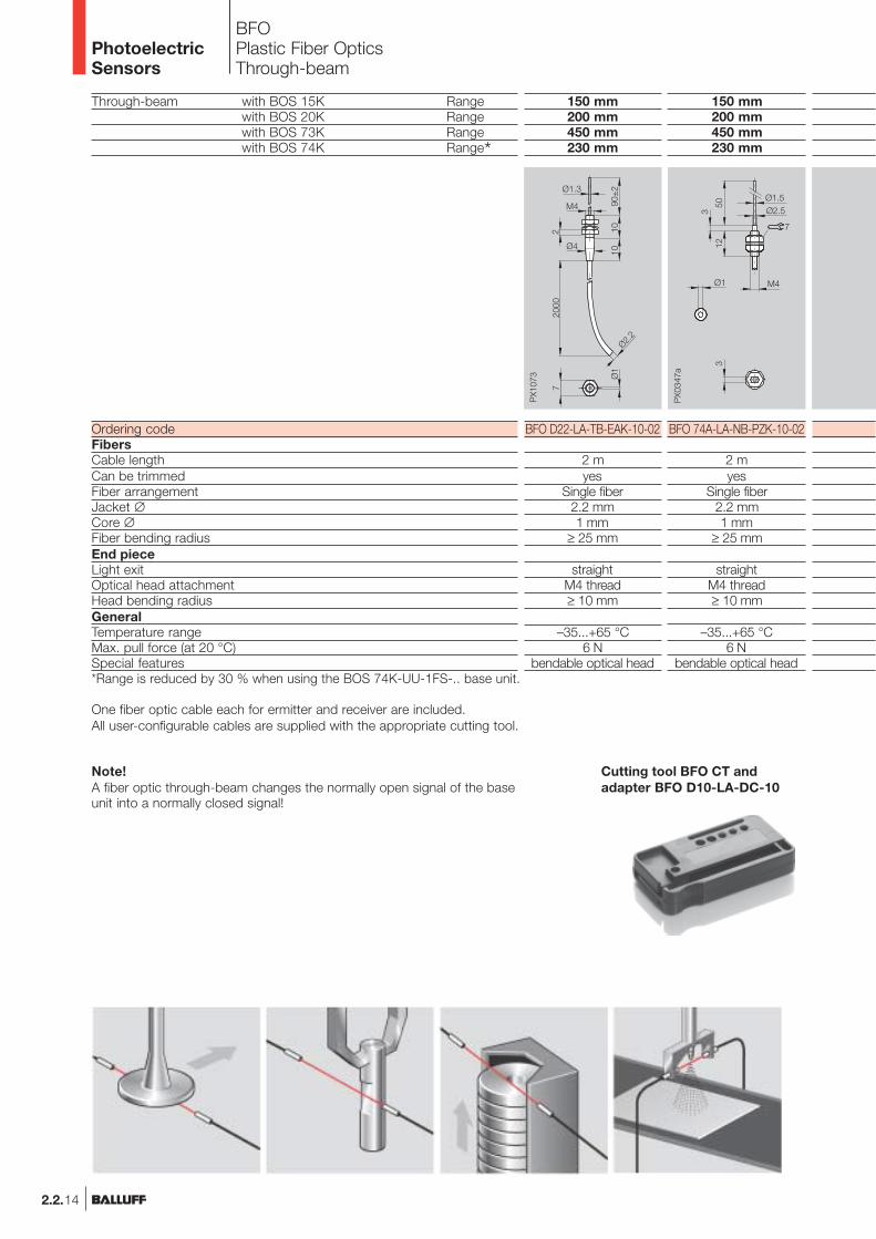
Through-beam with BOS 15K Rangewith BOS 20K Rangewith BOS 73K Rangewith BOS 74K Range*
Ordering codeFibersCable lengthCan be trimmedFiber arrangementJacket ∅Core ∅Fiber bending radiusEnd pieceLight exitOptical head attachmentHead bending radiusGeneralTemperature rangeMax. pull force (at 20 °C)Special features
BFOPlastic Fiber OpticsThrough-beam
150 mm200 mm450 mm230 mm
BFO 74A-LA-NB-PZK-10-02
2 myes
Single fiber2.2 mm1 mm
≥ 25 mm
straightM4 thread≥ 10 mm
–35...+65 °C6 N
bendable optical head
150 mm200 mm450 mm230 mm
BFO D22-LA-TB-EAK-10-02
2 myes
Single fiber2.2 mm1 mm
≥ 25 mm
straightM4 thread≥ 10 mm
–35...+65 °C6 N
bendable optical head
Note!A fiber optic through-beam changes the normally open signal of the baseunit into a normally closed signal!
PhotoelectricSensors
*Range is reduced by 30 % when using the BOS 74K-UU-1FS-.. base unit.
One fiber optic cable each for ermitter and receiver are included.All user-configurable cables are supplied with the appropriate cutting tool.
2.2.14
Cutting tool BFO CT andadapter BFO D10-LA-DC-10
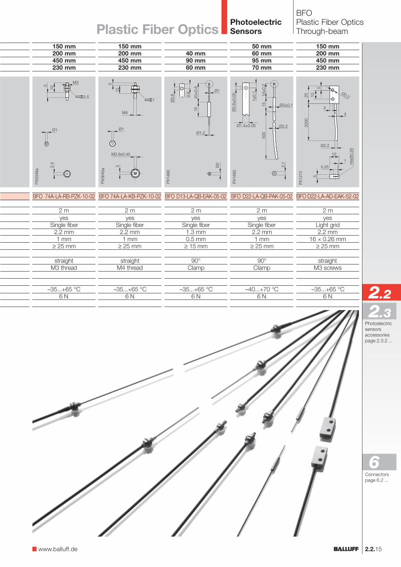
2.2.15
BFOPlastic Fiber OpticsThrough-beam
150 mm200 mm450 mm230 mm
BFO D22-LA-AD-EAK-52-02
2 myes
Light grid2.2 mm
16 × 0.26 mm≥ 25 mm
straightM3 screws
–35...+65 °C6 N
PhotoelectricSensors
150 mm200 mm450 mm230 mm
BFO 74A-LA-KB-PZK-10-02
2 myes
Single fiber2.2 mm1 mm
≥ 25 mm
straightM4 thread
–35...+65 °C6 N
150 mm200 mm450 mm230 mm
BFO 74A-LA-RB-PZK-10-02
2 myes
Single fiber2.2 mm1 mm
≥ 25 mm
straightM3 thread
–35...+65 °C6 N
40 mm90 mm60 mm
BFO D13-LA-QB-EAK-05-02
2 myes
Single fiber1.3 mm0.5 mm
≥ 15 mm
90°Clamp
–35...+65 °C6 N
50 mm60 mm95 mm70 mm
BFO D22-LA-QB-PAK-05-02
2 myes
Single fiber2.2 mm1 mm
≥ 25 mm
90°Clamp
–40...+70 °C6 N
Plastic Fiber Optics
www.balluff.de
2.2
2.3
6Connectorspage 6.2 ...
Photoelectricsensorsaccessoriespage 2.3.2 ...
Cutting tool BFO CT andadapter BFO D10-LA-DC-10
10 mm35 mm20 mm
BFO 74A-XA-HB-PZK-10-02
2 myes
duplex2 × 1 mm
2 × 0.5 mm≥ 15 mm
straightM4 thread≥ 10 mm
–35...+65 °C6 N
bendable optical head
15 mm15 mm35 mm20 mm
BFO N22-XA-VB-EAK-10-02
2 mno
duplex2 × 1 mm
2 × 0.5 mm≥ 15 mm
straightM3 thread≥ 10 mm
–35...+65 °C6 N
bendable optical head
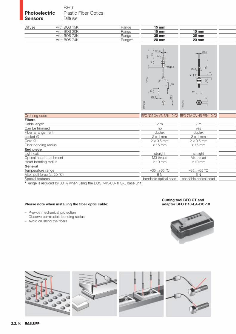
Diffuse with BOS 15K Rangewith BOS 20K Rangewith BOS 73K Rangewith BOS 74K Range*
Ordering codeFibersCable lengthCan be trimmedFiber arrangementJacket ∅Core ∅Fiber bending radiusEnd pieceLight exitOptical head attachmentHead bending radiusGeneralTemperature rangeMax. pull force (at 20 °C)Special features
*Range is reduced by 30 % when using the BOS 74K-UU-1FS-.. base unit.
BFOPlastic Fiber OpticsDiffuse
Please note when installing the fiber optic cable:
– Provide mechanical protection– Observe permissible bending radius– Avoid crushing the fibers
PhotoelectricSensors
2.2.16
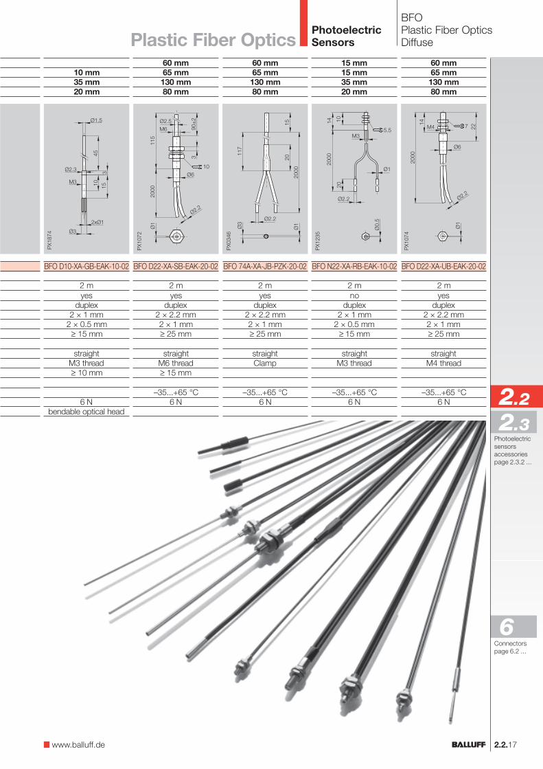
60 mm65 mm130 mm80 mm
BFO D22-XA-UB-EAK-20-02
2 myes
duplex2 × 2.2 mm2 × 1 mm≥ 25 mm
straightM4 thread
–35...+65 °C6 N
15 mm15 mm35 mm20 mm
BFO N22-XA-RB-EAK-10-02
2 mno
duplex2 × 1 mm
2 × 0.5 mm≥ 15 mm
straightM3 thread
–35...+65 °C6 N
60 mm65 mm130 mm80 mm
BFO 74A-XA-JB-PZK-20-02
2 myes
duplex2 × 2.2 mm2 × 1 mm≥ 25 mm
straightClamp
–35...+65 °C6 N
60 mm65 mm130 mm80 mm
BFO D22-XA-SB-EAK-20-02
2 myes
duplex2 × 2.2 mm2 × 1 mm≥ 25 mm
straightM6 thread≥ 15 mm
–35...+65 °C6 N
2.2.17
BFOPlastic Fiber OpticsDiffuse
PhotoelectricSensorsPlastic Fiber Optics
10 mm35 mm20 mm
BFO D10-XA-GB-EAK-10-02
2 myes
duplex2 × 1 mm
2 × 0.5 mm≥ 15 mm
straightM3 thread≥ 10 mm
6 Nbendable optical head
www.balluff.de
2.2
2.3
6Connectorspage 6.2 ...
Photoelectricsensorsaccessoriespage 2.3.2 ...
15 mm70 mm25 mm
BFO 74A-XB-KB-PZK-10-02
2 myes
coaxial2 × ≥ 1 mm
1 × 0.5 mm/4 × 0.25 mm≥ 15 mm
straightM4 thread
–35...+65 °C6 N
60 mm70 mm150 mm90 mm
BFO 74A-XB-LB-PZK-15-02
2 myes
coaxial2 × 2.2 mm
1 × 1 mm/16 × 0.25 mm≥ 25 mm
straightM6 thread
–35...+65 °C6 N
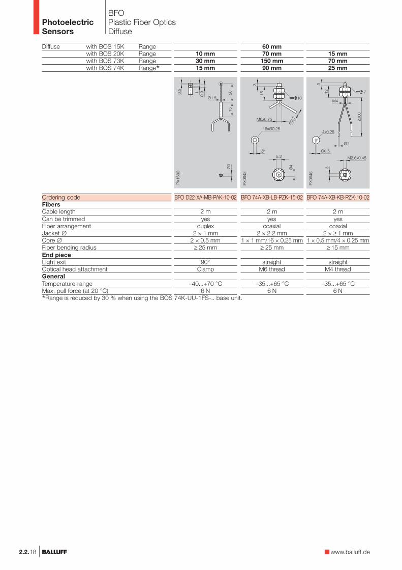
Diffuse with BOS 15K Rangewith BOS 20K Rangewith BOS 73K Rangewith BOS 74K Range*
Ordering codeFibersCable lengthCan be trimmedFiber arrangementJacket ∅Core ∅Fiber bending radiusEnd pieceLight exitOptical head attachmentGeneralTemperature rangeMax. pull force (at 20 °C)
BFOPlastic Fiber OpticsDiffuse
PhotoelectricSensors
*Range is reduced by 30 % when using the BOS 74K-UU-1FS-.. base unit.
2.2.18
10 mm30 mm15 mm
BFO D22-XA-MB-PAK-10-02
2 myes
duplex2 × 1 mm
2 × 0.5 mm≥ 25 mm
90°Clamp
–40...+70 °C6 N
www.balluff.de
2.2.19
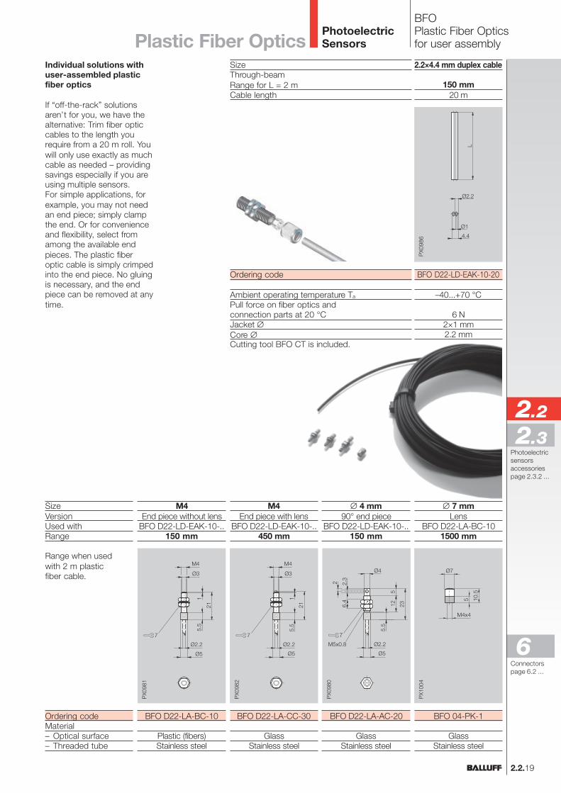
BFOPlastic Fiber Opticsfor user assembly
Individual solutions withuser-assembled plasticfiber optics
If “off-the-rack” solutionsaren’t for you, we have thealternative: Trim fiber opticcables to the length yourequire from a 20 m roll. Youwill only use exactly as muchcable as needed – providingsavings especially if you areusing multiple sensors.For simple applications, forexample, you may not needan end piece; simply clampthe end. Or for convenienceand flexibility, select fromamong the available endpieces. The plastic fiberoptic cable is simply crimpedinto the end piece. No gluingis necessary, and the endpiece can be removed at anytime.
2.2×4.4 mm duplex cable
150 mm20 m
BFO D22-LD-EAK-10-20
–40...+70 °C
6 N2×1 mm2.2 mm
SizeThrough-beamRange for L = 2 mCable length
Ordering code
Ambient operating temperature Ta
Pull force on fiber optics andconnection parts at 20 °CJacket ∅Core ∅Cutting tool BFO CT is included.
PhotoelectricSensors
∅ 7 mmLens
BFO D22-LA-BC-101500 mm
BFO 04-PK-1
GlassStainless steel
M4End piece with lens
BFO D22-LD-EAK-10-..450 mm
BFO D22-LA-CC-30
GlassStainless steel
M4End piece without lens
BFO D22-LD-EAK-10-..150 mm
BFO D22-LA-BC-10
Plastic (fibers)Stainless steel
SizeVersionUsed withRange
Range when usedwith 2 m plasticfiber cable.
Ordering codeMaterial– Optical surface– Threaded tube
∅ 4 mm90° end piece
BFO D22-LD-EAK-10-..150 mm
BFO D22-LA-AC-20
GlassStainless steel
Plastic Fiber Optics
2.2
2.3
6Connectorspage 6.2 ...
Photoelectricsensorsaccessoriespage 2.3.2 ...
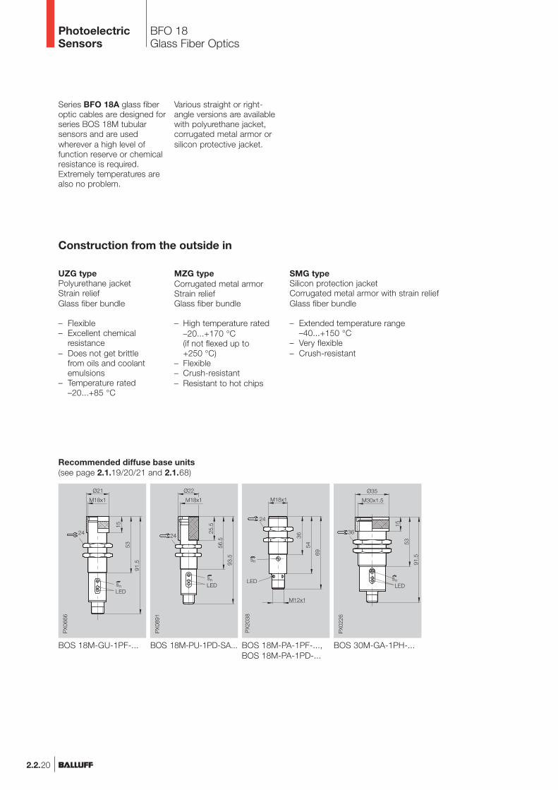
BFO 18Glass Fiber Optics
PhotoelectricSensors
MZG typeCorrugated metal armorStrain reliefGlass fiber bundle
– High temperature rated–20...+170 °C(if not flexed up to+250 °C)
– Flexible– Crush-resistant– Resistant to hot chips
Construction from the outside in
UZG typePolyurethane jacketStrain reliefGlass fiber bundle
– Flexible– Excellent chemical
resistance– Does not get brittle
from oils and coolantemulsions
– Temperature rated–20...+85 °C
SMG typeSilicon protection jacketCorrugated metal armor with strain reliefGlass fiber bundle
– Extended temperature range–40...+150 °C
– Very flexible– Crush-resistant
2.2.20
Series BFO 18A glass fiberoptic cables are designed forseries BOS 18M tubularsensors and are usedwherever a high level offunction reserve or chemicalresistance is required.Extremely temperatures arealso no problem.
Various straight or right-angle versions are availablewith polyurethane jacket,corrugated metal armor orsilicon protective jacket.
Recommended diffuse base units(see page 2.1.19/20/21 and 2.1.68)
BOS 18M-GU-1PF-... BOS 30M-GA-1PH-...BOS 18M-PU-1PD-SA... BOS 18M-PA-1PF-...,BOS 18M-PA-1PD-...
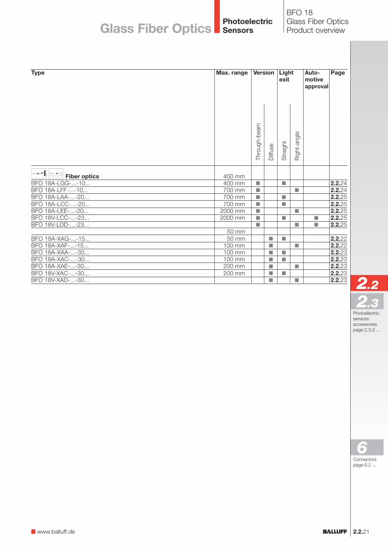
BFO 18Glass Fiber OpticsProduct overview
2.2.21
PhotoelectricSensorsGlass Fiber Optics
Type
Fiber opticsBFO 18A-LGG-...-10...BFO 18A-LFF-...-10...BFO 18A-LAA-...-20...BFO 18A-LCC-...-20...BFO 18A-LEE-...-20...BFO 18V-LCC-...-23...BFO 18V-LDD-...-23...
BFO 18A-XAG-...-15...BFO 18A-XAF-...-15...BFO 18A-XAA-...-30...BFO 18A-XAC-...-30...BFO 18A-XAE-...-30...BFO 18V-XAC-...-30...BFO 18V-XAD-...-30...
Lightexit
Auto-motiveapproval
Page
2.2.242.2.242.2.252.2.252.2.252.2.252.2.25
2.2.222.2.222.2.232.2.232.2.232.2.232.2.23
Str
aigh
t
Rig
ht-a
ngle
Version
Thro
ugh-
beam
Diff
use
Max. range
400 mm400 mm700 mm700 mm700 mm
2000 mm2000 mm
50 mm50 mm
100 mm100 mm100 mm200 mm200 mm
www.balluff.de
2.2
2.3
6Connectorspage 6.2 ...
Photoelectricsensorsaccessoriespage 2.3.2 ...
Diffuse with BOS 18M-...-PD-.../BOS 18M-...-1PF-... RangeBOS 30M-... Range
Retroreflective with BOS 18M-...-PD-.../BOS 18M-...-1PF-... RangeBOS 30M-... Range
Ordering code Type UZGType MZGType SMG
Diameter of glass fiber bundleMax. pull force on fiber optics and connection partsMin. bending radiusFor use with BOS 18M-PA-1PD-...
BOS 18M-PU-1PD-SA 1.../-SA 4.../-SA 5...BOS 18M-GU-1PF-S4-YBOS 18M-PA-1PF-...BOS 30M-...
Range with BOS 18M-PA-1PD-...BOS 18M-PU-1PD-SA 1.../-SA 4.../-SA 5...BOS 18M-...-1PF-...BOS 30M-...
Range with BOS 18M-PA-1PD-...BOS 18M-PU-1PD-SA 1.../-SA 4.../-SA 5...BOS 18M-...-1PF-...BOS 30M-...
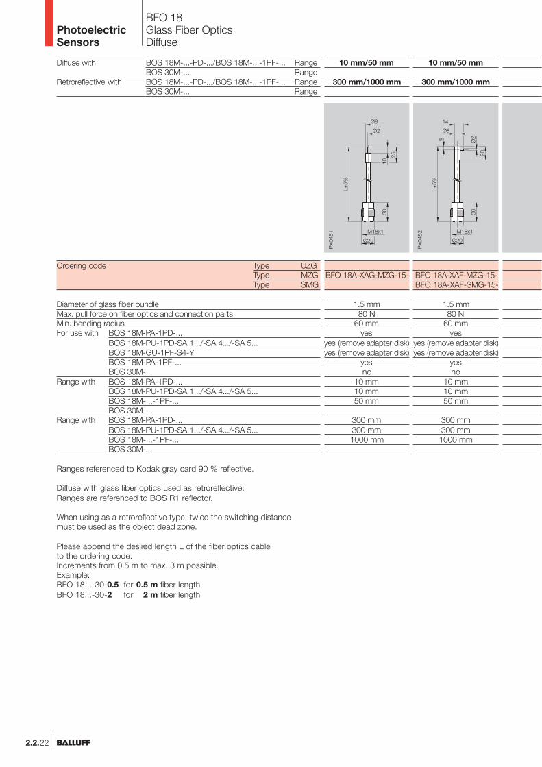
BFO 18Glass Fiber OpticsDiffuse
10 mm/50 mm
300 mm/1000 mm
BFO 18A-XAF-MZG-15-BFO 18A-XAF-SMG-15-
1.5 mm80 N
60 mmyes
yes (remove adapter disk)yes (remove adapter disk)
yesno
10 mm10 mm50 mm
300 mm300 mm1000 mm
10 mm/50 mm
300 mm/1000 mm
BFO 18A-XAG-MZG-15-
1.5 mm80 N
60 mmyes
yes (remove adapter disk)yes (remove adapter disk)
yesno
10 mm10 mm50 mm
300 mm300 mm1000 mm
Ranges referenced to Kodak gray card 90 % reflective.
Diffuse with glass fiber optics used as retroreflective:Ranges are referenced to BOS R1 reflector.
When using as a retroreflective type, twice the switching distancemust be used as the object dead zone.
Please append the desired length L of the fiber optics cableto the ordering code.Increments from 0.5 m to max. 3 m possible.Example:BFO 18...-30-0.5 for 0.5 m fiber lengthBFO 18...-30-2 for 2 m fiber length
PhotoelectricSensors
2.2.22
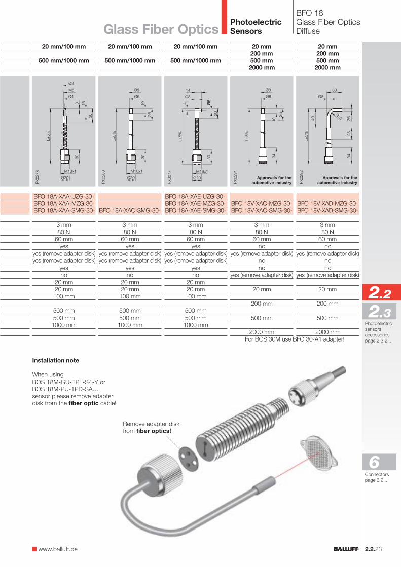
BFO 18Glass Fiber OpticsDiffuse
For BOS 30M use BFO 30-A1 adapter!
20 mm200 mm500 mm2000 mm
BFO 18V-XAD-MZG-30-BFO 18V-XAD-SMG-30-
3 mm80 N
60 mmno
yes (remove adapter disk)nono
yes (remove adapter disk)
20 mm
200 mm
500 mm
2000 mm
20 mm200 mm500 mm2000 mm
BFO 18V-XAC-MZG-30-BFO 18V-XAC-SMG-30-
3 mm80 N
60 mmno
yes (remove adapter disk)nono
yes (remove adapter disk)
20 mm
200 mm
500 mm
2000 mm
20 mm/100 mm
500 mm/1000 mm
BFO 18A-XAE-UZG-30-BFO 18A-XAE-MZG-30-BFO 18A-XAE-SMG-30-
3 mm80 N
60 mmyes
yes (remove adapter disk)yes (remove adapter disk)
yesno
20 mm20 mm100 mm
500 mm500 mm1000 mm
20 mm/100 mm
500 mm/1000 mm
BFO 18A-XAC-SMG-30-
3 mm80 N
60 mmyes
yes (remove adapter disk)yes (remove adapter disk)
yesno
20 mm20 mm100 mm
500 mm500 mm1000 mm
20 mm/100 mm
500 mm/1000 mm
BFO 18A-XAA-UZG-30-BFO 18A-XAA-MZG-30-BFO 18A-XAA-SMG-30-
3 mm80 N
60 mmyes
yes (remove adapter disk)yes (remove adapter disk)
yesno
20 mm20 mm100 mm
500 mm500 mm1000 mm
2.2.23
Approvals for theautomotive industry
Approvals for theautomotive industry
PhotoelectricSensors
Installation note
When usingBOS 18M-GU-1PF-S4-Y orBOS 18M-PU-1PD-SA…sensor please remove adapterdisk from the fiber optic cable!
Remove adapter diskfrom fiber optics!
Glass Fiber Optics
www.balluff.de
2.2
2.3
6Connectorspage 6.2 ...
Photoelectricsensorsaccessoriespage 2.3.2 ...

Through-beam with BOS 18M-...-PD-... RangeBOS 18M-...-1PF-... RangeBOS 30M-... Range
Ordering code Type UZGType MZGType SMG
Diameter of glass fiber bundleMax. pull force on fiber optics and connection partsMin. bending radiusFor use with BOS 18M-PA-1PD-...
BOS 18M-PU-1PD-SA 1.../-SA 4.../-SA 5...BOS 18M-GU-1PF-...BOS 18M-PA-1PF-...BOS 30M-...
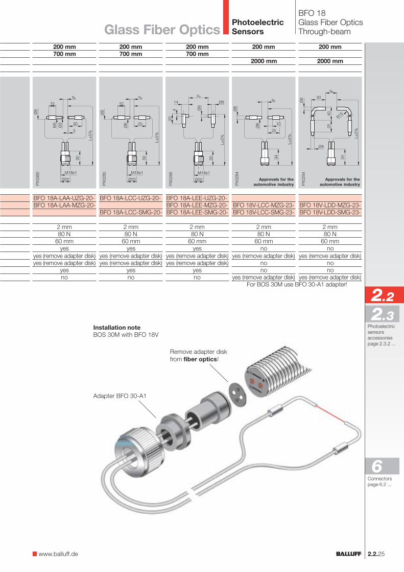
BFO 18Glass Fiber OpticsThrough-beam
100 mm400 mm
BFO 18A-LGG-MZG-10-BFO 18A-LGG-SMG-10-
1 mm80 N
60 mmyes
yes (remove adapter disk)yes (remove adapter disk)
yesno
100 mm400 mm
BFO 18A-LFF-MZG-10-BFO 18A-LFF-SMG-10-
1 mm80 N
60 mmyes
yes (remove adapter disk)yes (remove adapter disk)
yesno
Please append the desired length L of the fiber optics cable to the ordering code.Increments from 0.5 m to max. 3 m possible.Example:BFO 18...-20-0.5 for 0.5 m fiber lengthBFO 18...-20-2 for 2 m fiber length
Note!A through-beam fiber optic cable changes the normally open signal of the base unitinto a normally closed signal!
PhotoelectricSensors
2.2.24
2.2.25
BFO 18Glass Fiber OpticsThrough-beam
200 mm
2000 mm
BFO 18V-LDD-MZG-23-BFO 18V-LDD-SMG-23-
2 mm80 N
60 mmno
yes (remove adapter disk)nono
yes (remove adapter disk)
200 mm
2000 mm
BFO 18V-LCC-MZG-23-BFO 18V-LCC-SMG-23-
2 mm80 N
60 mmno
yes (remove adapter disk)nono
yes (remove adapter disk)
200 mm700 mm
BFO 18A-LEE-UZG-20-BFO 18A-LEE-MZG-20-BFO 18A-LEE-SMG-20-
2 mm80 N
60 mmyes
yes (remove adapter disk)yes (remove adapter disk)
yesno
200 mm700 mm
BFO 18A-LCC-UZG-20-
BFO 18A-LCC-SMG-20-
2 mm80 N
60 mmyes
yes (remove adapter disk)yes (remove adapter disk)
yesno
Approvals for theautomotive industry
Approvals for theautomotive industry
For BOS 30M use BFO 30-A1 adapter!
PhotoelectricSensors
200 mm700 mm
BFO 18A-LAA-UZG-20-BFO 18A-LAA-MZG-20-
2 mm80 N
60 mmyes
yes (remove adapter disk)yes (remove adapter disk)
yesno
Remove adapter diskfrom fiber optics!
Adapter BFO 30-A1
Installation noteBOS 30M with BFO 18V
Glass Fiber Optics
www.balluff.de
2.2
2.3
6Connectorspage 6.2 ...
Photoelectricsensorsaccessoriespage 2.3.2 ...