borsig synthesis gas cooler process heat exchanger … · impurities, the high particulate burden...
TRANSCRIPT
SYNTHESIS GAS COOLERDOWNSTREAM OFPARTIAL OXIDATION OFOIL OR NATURAL GAS
BORSIGPROCESS HEATEXCHANGERGMBH
www.borsig.de/pro
1
ABOuT BORSIG PROCESS HEAT EXCHANGER GMBH
BORSIG Process Heat Exchanger GmbH, a member of the BORSIG Group, is the international leading manufacturer of pressure vessels and heat exchangers for cooling gases at very high temperatures (up to 1,500 °C) and high pressure (up to 35,000 kPa) for the chemical and petrochemical industries. These pressure vessels and heat exchangers are used for process stages in plants for the production of basic chemicals where they are installed directly at the downstream end of the cracking furnaces and/or reactors. BORSIG technology is also used in innovative coal gasification processes.
Our comprehensive know-how is based on more than 180 years of company history. The resulting competence, the perfectly trained specialists and our awareness of quality are the basis for the reliability of our products. This symbiosis is the source of our innovative power which is reflected by our unique manufacturing program.
State-of-the-art technology, excellent employees and innovative engineering allow us to always offer our customers the perfect solution. Our products and our service have made and still make us a competent and reliable partner to numerous companies across the world.
Our product range:
• Waste heat recovery systems (ammonia plants, methanol plants, hydrogen plants, coal gasification plants, gas-to-liquid plants, nitric acid plants, caprolactam plants, formaldehyde plants, partial oxidation of oil and gas)
• Transfer line exchangers in ethylene plants
• Scraped surface exchangers for lube oil plants and special applications
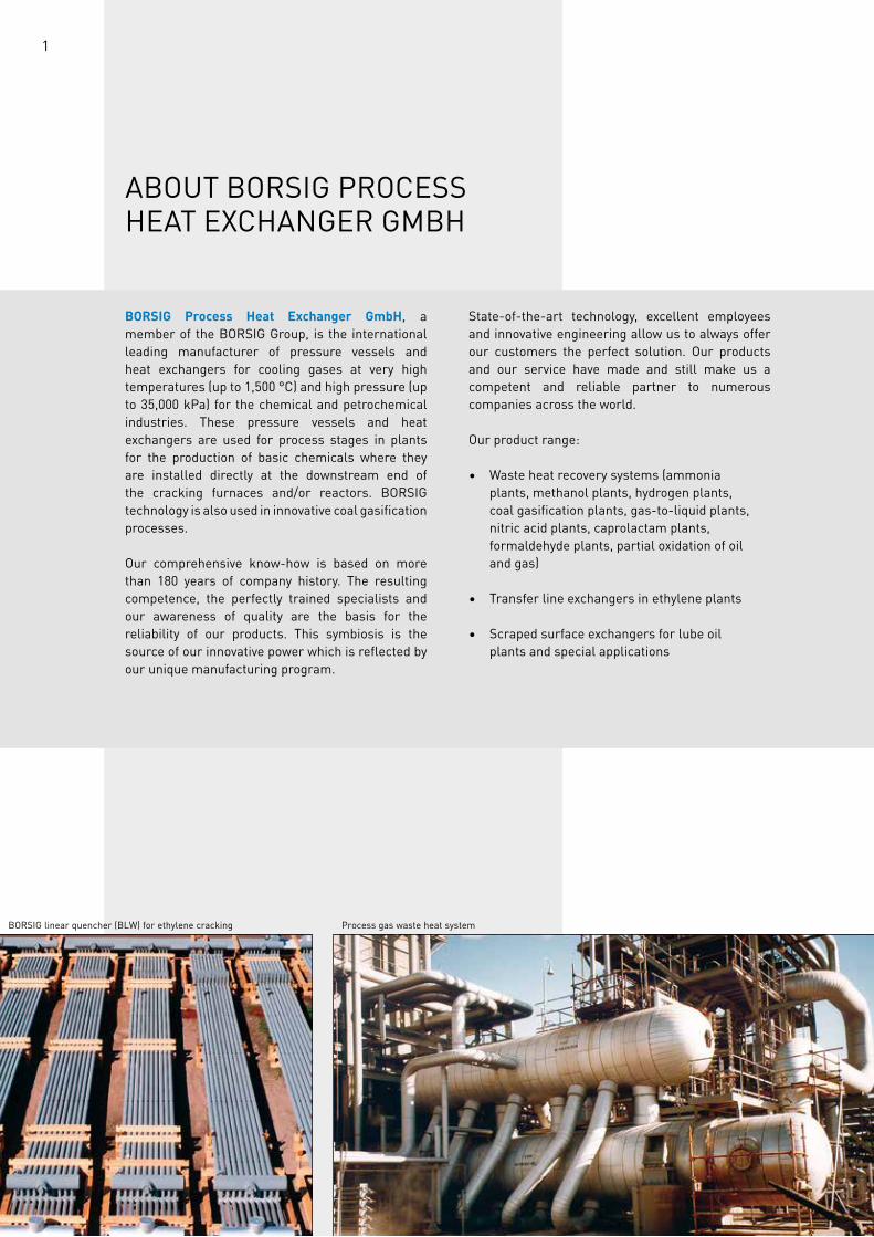
BORSIG linear quencher (BLW) for ethylene cracking Process gas waste heat system
2
SynTheSIS GaS COOLeR DOWnSTReam OfPaRTIaL OxIDaTIOn Of OIL OR naTuRaL GaS
The non-catalytic cracking of hydrocarbons by partial oxidation of natural gas, oil etc. is carried out at temperatures up to 1,500 °C and pressures up to 8,000 kPa. Besides the resulting reaction components CO, CO2, H2, H2O and H2S the process gas is loaded with soot and ash. Depending on the type of feedstock other impurities like vanadium, nickel and iron can also be expected. Due to these impurities, the high particulate burden of the gas and the hydrogen sulfide the waste heat boiler must be highly resistant to erosion, corrosion and fouling.
The process gas is cooled down in the waste heat boiler from about 1,400 °C to 300 °C. The heat of the gas is used to generate steam, the steam pressures are usually between 3,000 and 10,000 kPa. for special purposes it is also possible to integrate a superheater into the boiler.
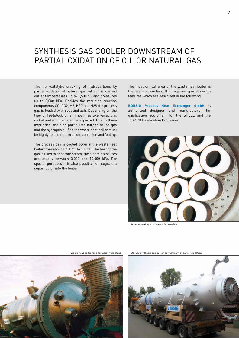
The most critical area of the waste heat boiler is the gas inlet section. This requires special design features which are described in the following.
BORSIG Process Heat Exchanger GmbH is authorized designer and manufacturer for gasification equipment for the SHELL and the TEXACO Gasification Processes.
Waste heat boiler for a formaldehyde plant BORSIG synthesis gas cooler downstream of partial oxidation
Ceramic coating of the gas inlet nozzles
3
SPeCIaL feaTuReS Of The BORSIG DESIGN
BORSIG Process Heat Exchanger GmbH has developed its own boiler design taking into account the high demands as already mentioned. This boiler design is suitable for all gasification processes, however, has been used yet mainly for the TEXACO Process. A sketch is shown on the right.
The waste heat boiler is designed as a fire-tube boiler. The hot synthesis gas enters the heating surfaces with a temperature of about 1,400 °C and is cooled down in these tubes to approximately 300 °C. The heat from the synthesis gas is used for generating saturated steam.
The tubes are designed as helical wound heating surfaces. Their diameter decreases in usually four to five steps to keep the gas velocity in the range of 25 to 35 m/s. This ensures a self-cleaning effect which is necessary due to the high particulate burden of the gas. A conical inlet section is used to reduce the turbulence at the inlets.
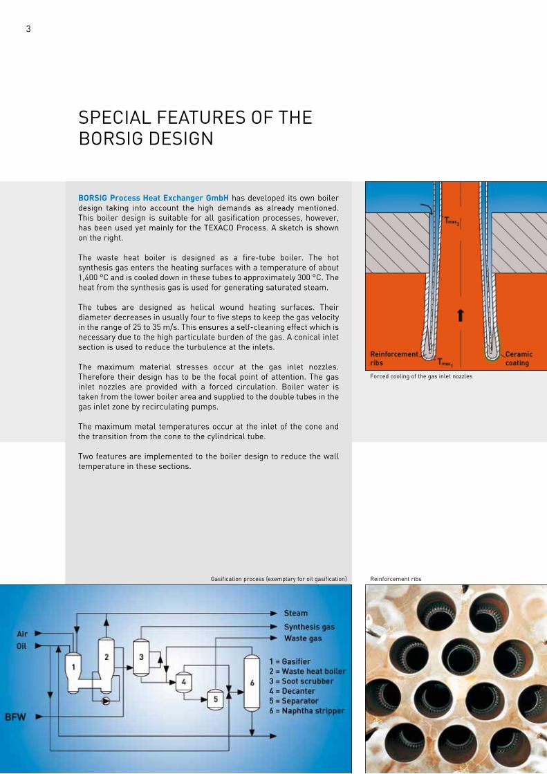
The maximum material stresses occur at the gas inlet nozzles. Therefore their design has to be the focal point of attention. The gas inlet nozzles are provided with a forced circulation. Boiler water is taken from the lower boiler area and supplied to the double tubes in the gas inlet zone by recirculating pumps.
The maximum metal temperatures occur at the inlet of the cone and the transition from the cone to the cylindrical tube.
Two features are implemented to the boiler design to reduce the wall temperature in these sections.
Gasification process (exemplary for oil gasification) Reinforcement ribs
forced cooling of the gas inlet nozzles
4
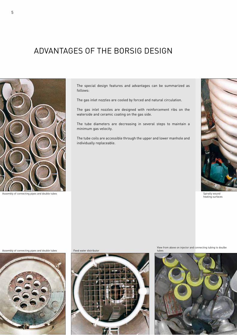
Reinforcement ribsOn the waterside the gas inlet nozzles are provided with reinforcement ribs. This allows to reduce the wall thickness and thereby the wall temperatures in this area. This design of the gas inlet nozzles with reinforcement ribs as described here is protected by patent.
Ceramic coatingThe application of a ceramic protection coating on the gasside of the inlet nozzles considerably improves the resistance to corrosion and erosion. The coating also reduces the wall temperatures due to its low conductivity.
Reinforcement ribs on waterside of the gas inlet nozzles Reinforcement ribs
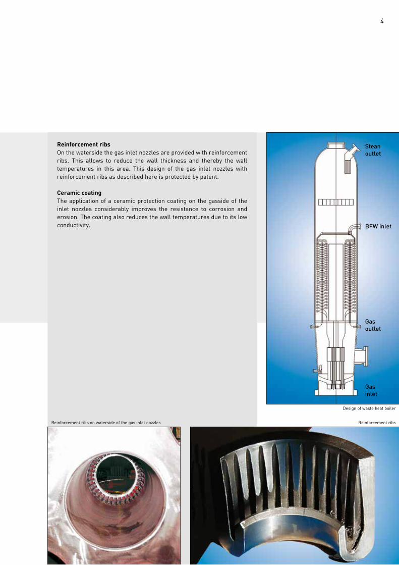
Design of waste heat boiler
Steanoutlet
BFW inlet
Gasoutlet
Gasinlet
5
aDvanTaGeS Of The BORSIG DeSIGn
The special design features and advantages can be summarized as follows:
The gas inlet nozzles are cooled by forced and natural circulation.
The gas inlet nozzles are designed with reinforcement ribs on the waterside and ceramic coating on the gas side.
The tube diameters are decreasing in several steps to maintain a minimum gas velocity.
The tube coils are accessible through the upper and lower manhole and individually replaceable.
Assembly of connecting pipes and double tubes feed water distributor
Assembly of connecting pipes and double tubes Spirally woundheating surfaces
View from above on injector and connecting tubing to doulbe tubes
6
RefeRenCeS
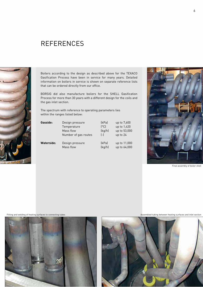
Boilers according to the design as described above for the TEXACO Gasification Process have been in service for many years. Detailed information on boilers in service is shown on separate reference lists that can be ordered directly from our office.
BORSIG did also manufacture boilers for the SHELL Gasification Process for more than 30 years with a different design for the coils and the gas inlet section.
The spectrum with reference to operating parameters lies within the ranges listed below:
Gasside: Design pressure (kPa) up to 7,600 Temperature (°C) up to 1,420 Mass flow (kg/h) up to 53,000 Number of gas routes (-) up to 24
Waterside: Design pressure (kPa) up to 11,000 Mass flow (kg/h) up to 64,000
fitting and welding of heating surfaces to connecting tubes Assembled tubing between heating surfaces and inlet section
final assembly of boiler shell
7
enGIneeRInG anD afTeR SaLeS SeRvICe
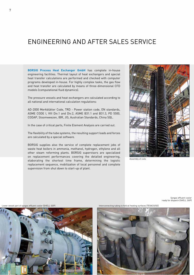
BORSIG Process Heat Exchanger GmbH has complete in-house engineering facilities. Thermal layout of heat exchangers and special heat transfer calculations are performed and checked with computer programs developed in-house. for highly complex tasks, the gas flow and heat transfer are calculated by means of three-dimensional CfD models (computational fluid dynamics).
The pressure vessels and heat exchangers are calculated according to all national and international calculation regulations:
AD-2000 Merkblätter Code, TRD - Power station code, EN standards, ASME CODE I, VIII Div.1 and Div.2, ASME B31.1 and B31.3, PD 5500, CODAP, Stoomweezen, IBR, JIS, Australian Standards, China SQL.
In the case of critical parts, finite element analysis are carried out.
The flexibility of the tube systems, the resulting support loads and forces are calculated by a special software.
BORSIG supplies also the service of complete replacement jobs of waste heat boilers in ammonia, methanol, hydrogen, ethylene and all other steam reforming plants. BORSIG supervisors are specialized on replacement performances covering the detailed engineering, elaborating the shortest time frame, determining the logistic replacement sequence, mobilization of local personnel and complete supervision from shut down to start-up of plant.
Lower vessel part of syngas effluent cooler (SHELL SGP)
Assembly of coils
Interconnecting tubing to helical heating surfaces (TEXACO/GE)
Syngas effluent coolerready for dispatch (SHELL SGP)
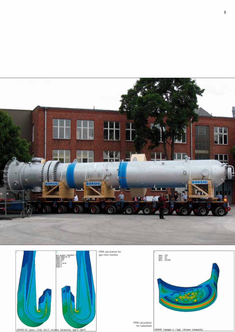
8
fem calculation forgas inlet nozzles
fem calculationfor tubesheet
9
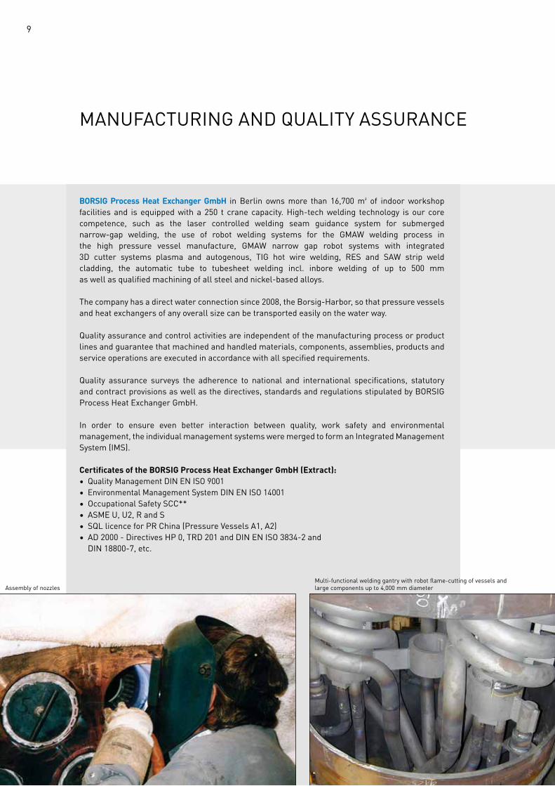
manufaCTuRInG anD QuaLITy aSSuRanCe
BORSIG Process Heat Exchanger GmbH in Berlin owns more than 16,700 m² of indoor workshop facilities and is equipped with a 250 t crane capacity. High-tech welding technology is our core competence, such as the laser controlled welding seam guidance system for submerged narrow-gap welding, the use of robot welding systems for the GmaW welding process in the high pressure vessel manufacture, GmaW narrow gap robot systems with integrated 3D cutter systems plasma and autogenous, TIG hot wire welding, ReS and SaW strip weld cladding, the automatic tube to tubesheet welding incl. inbore welding of up to 500 mm as well as qualified machining of all steel and nickel-based alloys.
The company has a direct water connection since 2008, the Borsig-Harbor, so that pressure vessels and heat exchangers of any overall size can be transported easily on the water way.
Quality assurance and control activities are independent of the manufacturing process or product lines and guarantee that machined and handled materials, components, assemblies, products and service operations are executed in accordance with all specified requirements.
Quality assurance surveys the adherence to national and international specifications, statutory and contract provisions as well as the directives, standards and regulations stipulated by BORSIG Process Heat Exchanger GmbH.
In order to ensure even better interaction between quality, work safety and environmental management, the individual management systems were merged to form an Integrated Management System (IMS).
Certificates of the BORSIG Process Heat Exchanger GmbH (Extract):• Quality Management DIN EN ISO 9001• Environmental Management System DIN EN ISO 14001• Occupational Safety SCC**• ASME u, u2, R and S• SQL licence for PR China (Pressure Vessels A1, A2)• AD 2000 - Directives HP 0, TRD 201 and DIN EN ISO 3834-2 and DIN 18800-7, etc.
Assembly of nozzlesMulti-functional welding gantry with robot flame-cutting of vessels and large components up to 4,000 mm diameter
10
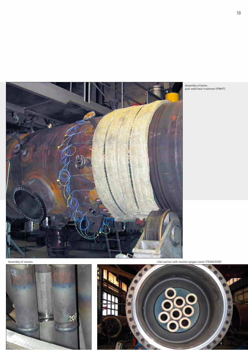
Assembly of nozzles Inlet section with nozzles syngas cooler (TEXACO/GE)
Assembly of boiler,post weld heat treatment (PWhT)
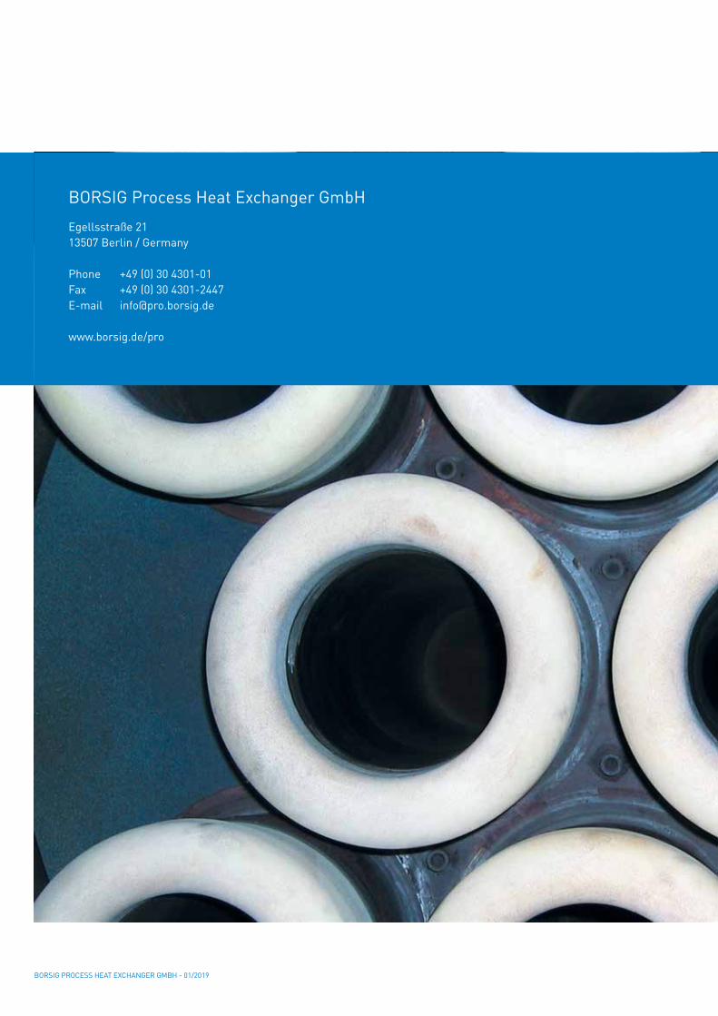
BORSIG Process Heat Exchanger GmbHEgellsstraße 21 13507 Berlin / Germany
Phone +49 (0) 30 4301-01 fax +49 (0) 30 4301-2447E-mail [email protected]
www.borsig.de/pro
BORSIG PROCESS HEAT EXCHANGER GMBH - 01/2019