borsig process gas process heat exchanger waste heat ... · borsig process heat exchanger gmbh, a...
TRANSCRIPT
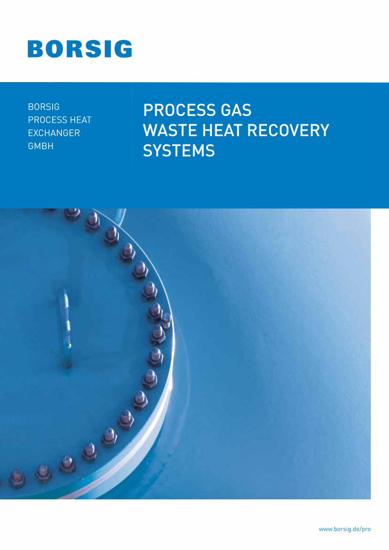
PROCESS GAS WASTE HEAT RECOVERYSYSTEMS
BORSIGPROCESS HEATEXCHANGERGMBH
www.borsig.de/pro

ABOuT BORSIG PROCESS HEAT EXCHANGER GMBH
BORSIG Process Heat Exchanger GmbH, a member of the BORSIG Group, is the international leading manufacturer of pressure vessels and heat exchangers for cooling gases at very high temperatures (up to 1,500 °C) and high pressure (up to 35,000 kPa) for the chemical and petrochemical industries. These pressure vessels and heat exchangers are used for process stages in plants for the production of basic chemicals where they are installed directly at the downstream end of the cracking furnaces and/or reactors. BORSIG technology is also used in innovative coal gasification processes. Our comprehensive know-how is based on more than 180 years of company history. The resulting competence, the perfectly trained specialists and our awareness of quality are the basis for the reliability of our products. This symbiosis is the source of our innovative power which is reflected by our unique manufacturing program.State-of-the-art technology, excellent employees and innovative engineering allow us to always offer our customers the perfect solution. Our products and our service have made and still make us a competent and reliable partner to numerous companies across the world.
Our product range:
• Waste heat recovery systems (ammonia plants, methanol plants, hydrogen plants, coal gasification plants, gas-to-liquid plants, nitric acid plants, caprolactam plants, formaldehyde plants, partial oxidation of oil and gas)
• Transfer line exchangers in ethylene plants
• Scraped surface exchangers for lube oil plants and special applications
Process gas waste heat boiler
“Tunnelflow” transfer line exchangers Linear transfer line exchangers Scraped surface exchanger
1
PROCESS GAS WASTE HEAT RECOvERy SySTEMS
2
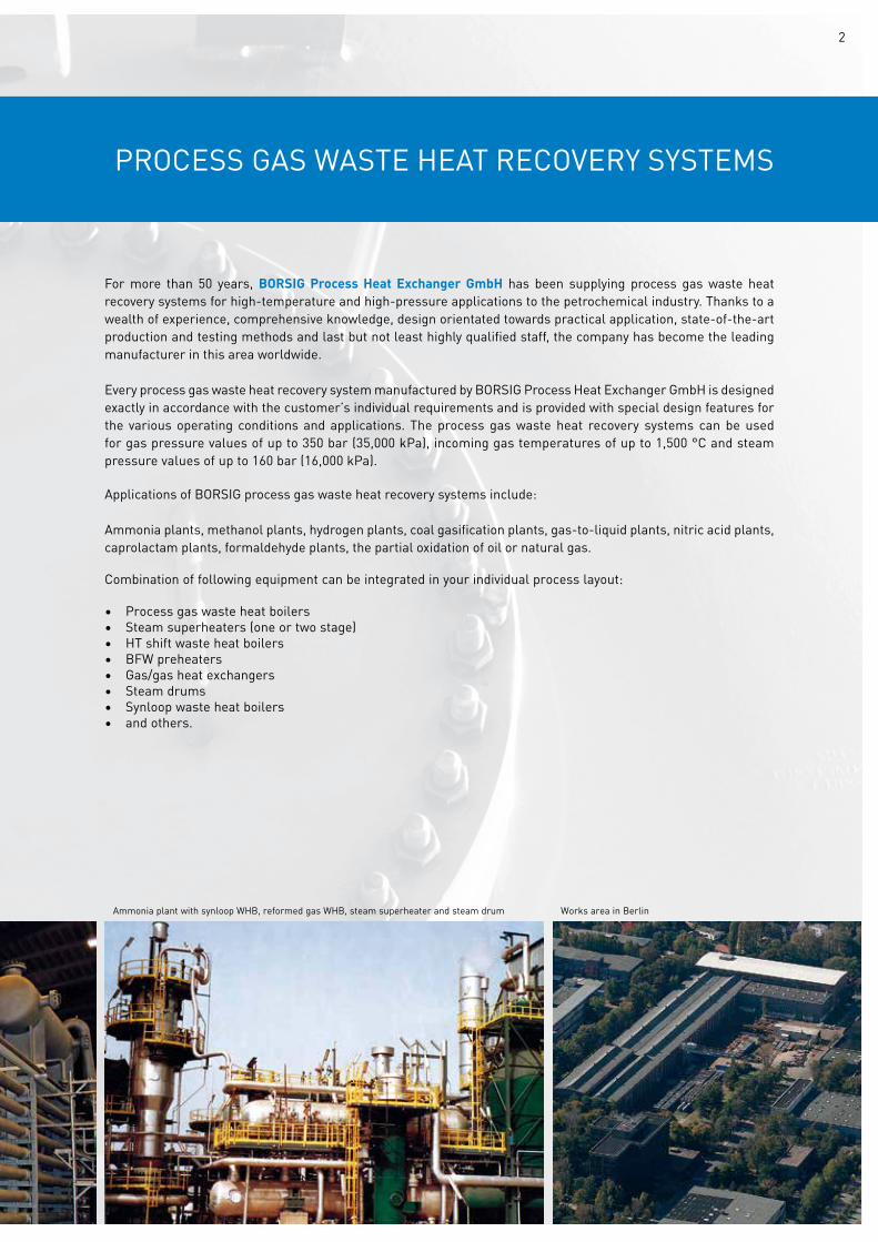
Ammonia plant with synloop WHB, reformed gas WHB, steam superheater and steam drum Works area in Berlin
For more than 50 years, BORSIG Process Heat Exchanger GmbH has been supplying process gas waste heat recovery systems for high-temperature and high-pressure applications to the petrochemical industry. Thanks to a wealth of experience, comprehensive knowledge, design orientated towards practical application, state-of-the-art production and testing methods and last but not least highly qualified staff, the company has become the leading manufacturer in this area worldwide.
Every process gas waste heat recovery system manufactured by BORSIG Process Heat Exchanger GmbH is designed exactly in accordance with the customer’s individual requirements and is provided with special design features for the various operating conditions and applications. The process gas waste heat recovery systems can be used for gas pressure values of up to 350 bar (35,000 kPa), incoming gas temperatures of up to 1,500 °C and steam pressure values of up to 160 bar (16,000 kPa).
Applications of BORSIG process gas waste heat recovery systems include:
Ammonia plants, methanol plants, hydrogen plants, coal gasification plants, gas-to-liquid plants, nitric acid plants, caprolactam plants, formaldehyde plants, the partial oxidation of oil or natural gas.
Combination of following equipment can be integrated in your individual process layout:
• Process gas waste heat boilers• Steam superheaters (one or two stage)• HT shift waste heat boilers• BFW preheaters• Gas/gas heat exchangers• Steam drums• Synloop waste heat boilers• and others.
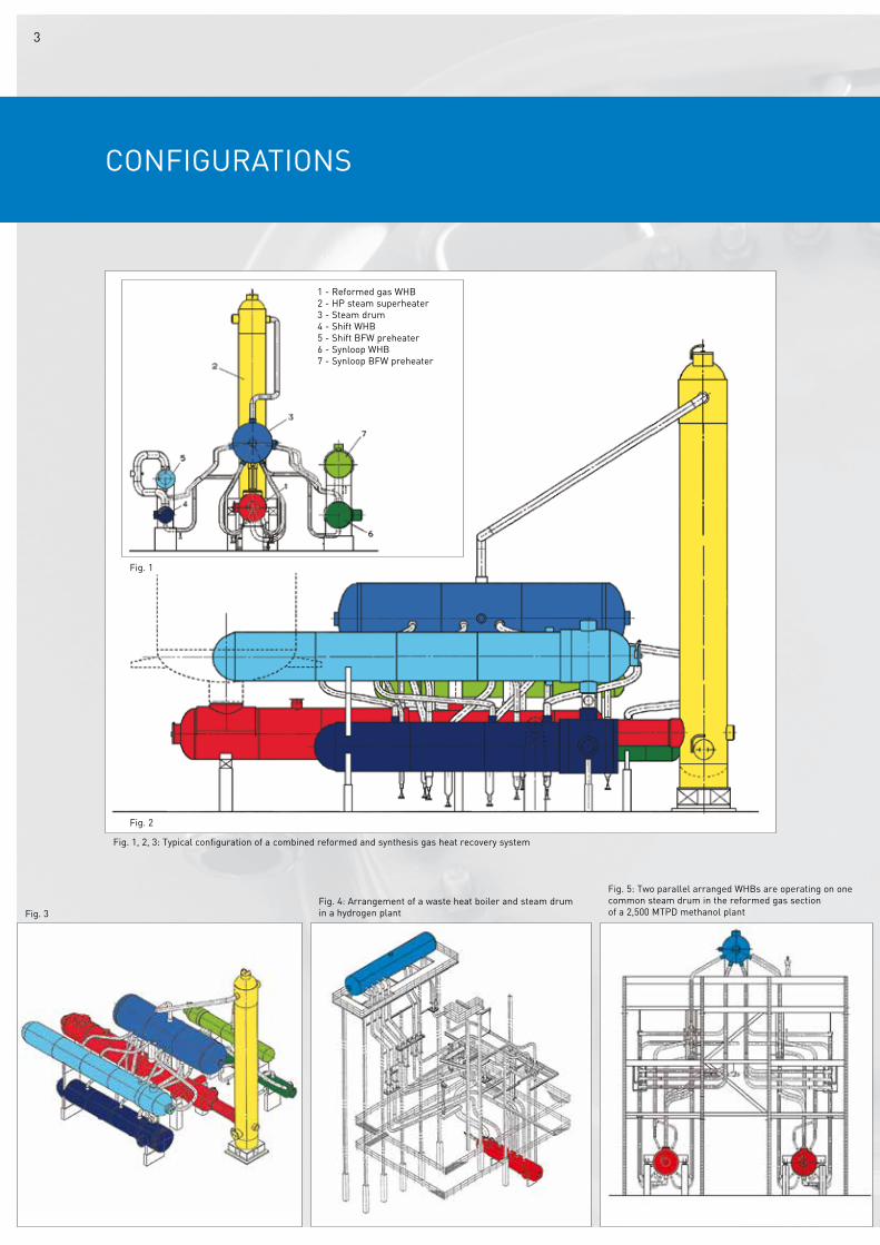
CONFIGuRATIONS
Fig. 2
Fig. 1
1 - Reformed gas WHB2 - HP steam superheater3 - Steam drum4 - Shift WHB5 - Shift BFW preheater6 - Synloop WHB7 - Synloop BFW preheater
Fig. 1, 2, 3: Typical configuration of a combined reformed and synthesis gas heat recovery system
Fig. 3Fig. 4: Arrangement of a waste heat boiler and steam drum in a hydrogen plant
Fig. 5: Two parallel arranged WHBs are operating on one common steam drum in the reformed gas section of a 2,500 MTPD methanol plant
3
PROCESS GAS WASTE HEAT BOILERS
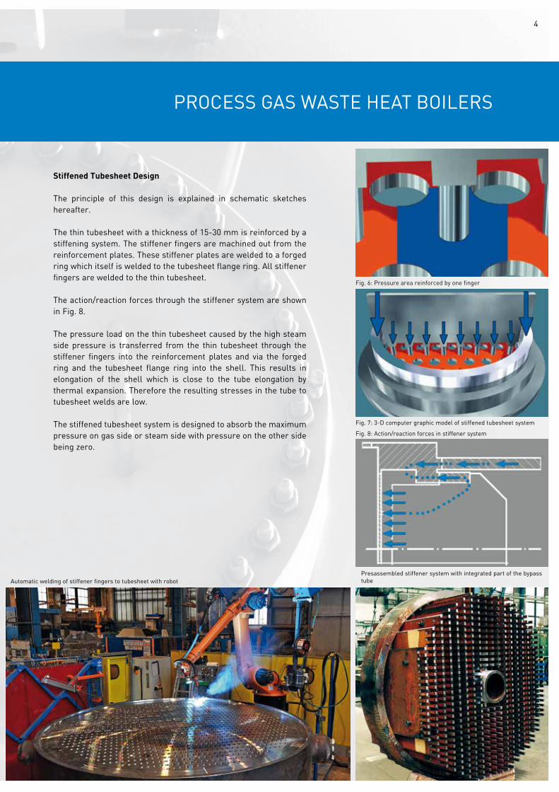
Stiffened Tubesheet Design
The principle of this design is explained in schematic sketches hereafter.
The thin tubesheet with a thickness of 15-30 mm is reinforced by a stiffening system. The stiffener fingers are machined out from the reinforcement plates. These stiffener plates are welded to a forged ring which itself is welded to the tubesheet flange ring. All stiffener fingers are welded to the thin tubesheet.
The action/reaction forces through the stiffener system are shown in Fig. 8.
The pressure load on the thin tubesheet caused by the high steam side pressure is transferred from the thin tubesheet through the stiffener fingers into the reinforcement plates and via the forged ring and the tubesheet flange ring into the shell. This results in elongation of the shell which is close to the tube elongation by thermal expansion. Therefore the resulting stresses in the tube to tubesheet welds are low.
The stiffened tubesheet system is designed to absorb the maximum pressure on gas side or steam side with pressure on the other side being zero.
Automatic welding of stiffener fingers to tubesheet with robotPresassembled stiffener system with integrated part of the bypass tube
Fig. 8: Action/reaction forces in stiffener system
Fig. 7: 3-D computer graphic model of stiffened tubesheet system
Fig. 6: Pressure area reinforced by one finger
4
TuBE TO TuBESHEET WELD
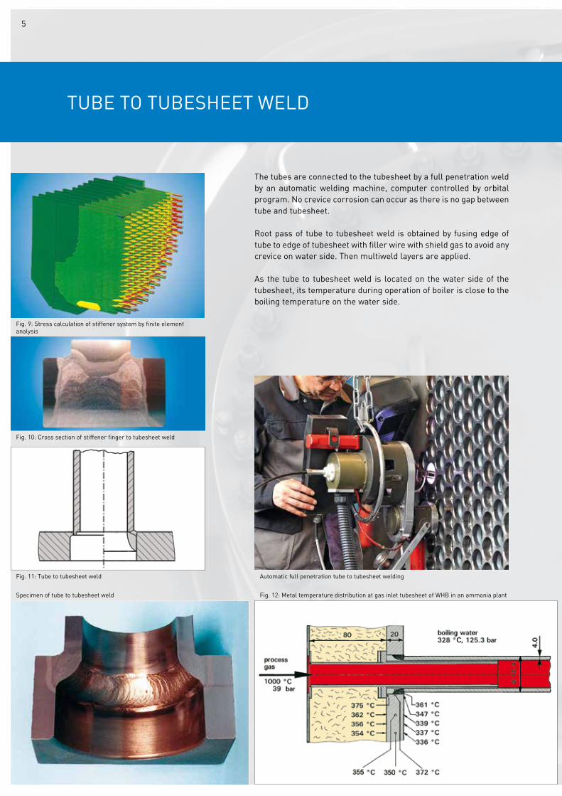
The tubes are connected to the tubesheet by a full penetration weld by an automatic welding machine, computer controlled by orbital program. No crevice corrosion can occur as there is no gap between tube and tubesheet.
Root pass of tube to tubesheet weld is obtained by fusing edge of tube to edge of tubesheet with filler wire with shield gas to avoid any crevice on water side. Then multiweld layers are applied.
As the tube to tubesheet weld is located on the water side of the tubesheet, its temperature during operation of boiler is close to the boiling temperature on the water side.
Fig. 9: Stress calculation of stiffener system by finite element analysis
Fig. 10: Cross section of stiffener finger to tubesheet weld
Fig. 11: Tube to tubesheet weld Automatic full penetration tube to tubesheet welding
Fig. 12: Metal temperature distribution at gas inlet tubesheet of WHB in an ammonia plantSpecimen of tube to tubesheet weld
5
GAS SIDE ByPASS vALvE (BORSIG PATENTED)
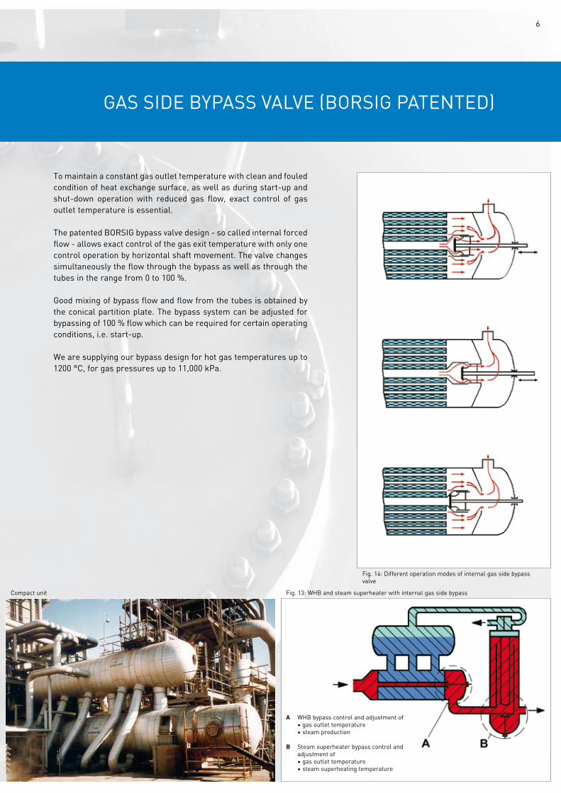
To maintain a constant gas outlet temperature with clean and fouled condition of heat exchange surface, as well as during start-up and shut-down operation with reduced gas flow, exact control of gas outlet temperature is essential.
The patented BORSIG bypass valve design - so called internal forced flow - allows exact control of the gas exit temperature with only one control operation by horizontal shaft movement. The valve changes simultaneously the flow through the bypass as well as through the tubes in the range from 0 to 100 %.
Good mixing of bypass flow and flow from the tubes is obtained by the conical partition plate. The bypass system can be adjusted for bypassing of 100 % flow which can be required for certain operating conditions, i.e. start-up.
We are supplying our bypass design for hot gas temperatures up to 1200 °C, for gas pressures up to 11,000 kPa.
Compact unit
A WHB bypass control and adjustment of • gas outlet temperature • steam production
B Steam superheater bypass control and adjustment of • gas outlet temperature • steam superheating temperature
Fig. 13: WHB and steam superheater with internal gas side bypass
Fig. 14: Different operation modes of internal gas side bypass valve
6
STIFFENED TuBESHEET DESIGN (BORSIG PATENTED)
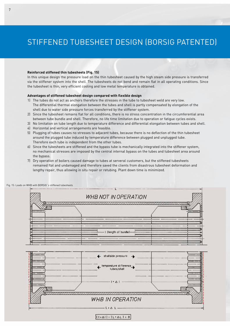
Reinforced stiffened thin tubesheets (Fig. 15)In this unique design the pressure load on the thin tubesheet caused by the high steam side pressure is transferred via the stiffener system into the shell. The tubesheets do not bend and remain flat in all operating conditions. Since the tubesheet is thin, very efficient cooling and low metal temperature is obtained.
Advantages of stiffened tubesheet design compared with flexible design1) The tubes do not act as anchors therefore the stresses in the tube to tubesheet weld are very low. The differential thermal elongation between the tubes and shell is partly compensated by elongation of the shell due to water side pressure forces transferred by the stiffener system.2) Since the tubesheet remains flat for all conditions, there is no stress concentration in the circumferential area between tube bundle and shell. Therefore, no life time limitation due to operation or fatigue cycles exists.3) No limitation on tube length due to temperature difference and differential elongation between tubes and shell.4) Horizontal and vertical arrangements are feasible.5) Plugging of tubes causes no stresses to adjacent tubes, because there is no deflection of the thin tubesheet around the plugged tube induced by temperature difference between plugged and unplugged tube. Therefore each tube is independent from the other tubes.6) Since the tubesheets are stiffened and the bypass tube is mechanically integrated into the stiffener system, no mechanical stresses are imposed by the central internal bypass on the tubes and tubesheet area around the bypass.7) Dry operation of boilers caused damage to tubes at serveral customers, but the stiffened tubesheets remained flat and undamaged and therefore saved the clients from disastrous tubesheet deformation and lengthy repair, thus allowing in situ repair or retubing. Plant down time is minimized.
Fig. 15: Loads on WHB with BORSIG´s stiffened tubesheets
7
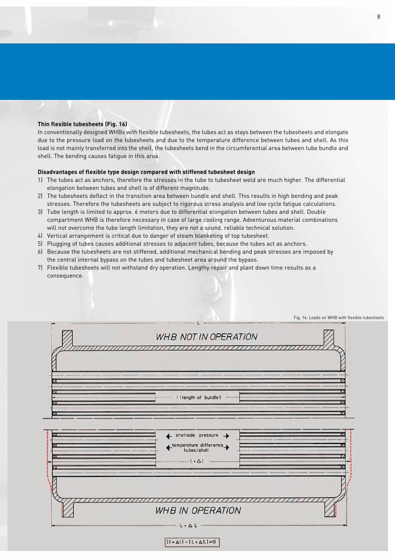
Thin flexible tubesheets (Fig. 16)In conventionally designed WHBs with flexible tubesheets, the tubes act as stays between the tubesheets and elongate due to the pressure load on the tubesheets and due to the temperature difference between tubes and shell. As this load is not mainly transferred into the shell, the tubesheets bend in the circumferential area between tube bundle and shell. The bending causes fatigue in this area.
Disadvantages of flexible type design compared with stiffened tubesheet design1) The tubes act as anchors, therefore the stresses in the tube to tubesheet weld are much higher. The differential elongation between tubes and shell is of different magnitude.2) The tubesheets deflect in the transition area between bundle and shell. This results in high bending and peak stresses. Therefore the tubesheets are subject to rigorous stress analysis and low cycle fatigue calculations.3) Tube length is limited to approx. 6 meters due to differential elongation between tubes and shell. Double compartment WHB is therefore necessary in case of large cooling range. Adventurous material combinations will not overcome the tube length limitation, they are not a sound, reliable technical solution.4) vertical arrangement is critical due to danger of steam blanketing of top tubesheet.5) Plugging of tubes causes additional stresses to adjacent tubes, because the tubes act as anchors.6) Because the tubesheets are not stiffened, additional mechanical bending and peak stresses are imposed by the central internal bypass on the tubes and tubesheet area around the bypass.7) Flexible tubesheets will not withstand dry operation. Lengthy repair and plant down time results as a consequence.
Fig. 16: Loads on WHB with flexible tubesheets
8
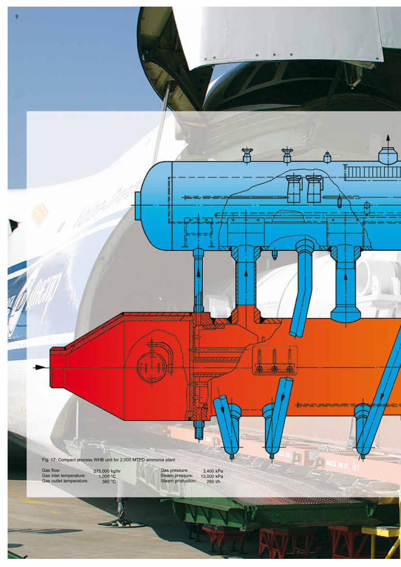
Fig. 17: Compact process WHB unit for 2,000 MTPD ammonia plant
Gas flow: Gas pressure: Gas inlet temperature: Steam pressure: Gas outlet temperature: Steam production:
275,0001,000
360
kg/hr °C°C
3,40013,000
280
kPakPat/h
9
10
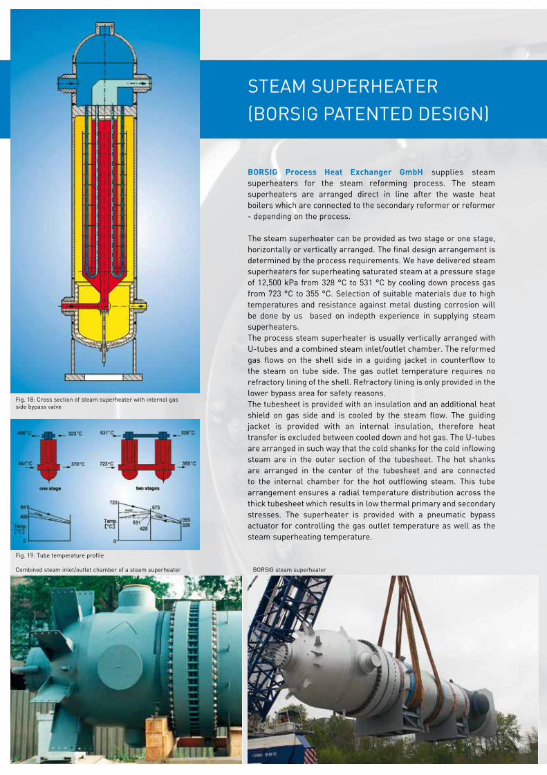
STEAM SuPERHEATER(BORSIG PATENTED DESIGN)
BORSIG Process Heat Exchanger GmbH supplies steam superheaters for the steam reforming process. The steam superheaters are arranged direct in line after the waste heat boilers which are connected to the secondary reformer or reformer - depending on the process.
The steam superheater can be provided as two stage or one stage, horizontally or vertically arranged. The final design arrangement is determined by the process requirements. We have delivered steam superheaters for superheating saturated steam at a pressure stage of 12,500 kPa from 328 °C to 531 °C by cooling down process gas from 723 °C to 355 °C. Selection of suitable materials due to high temperatures and resistance against metal dusting corrosion will be done by us based on indepth experience in supplying steam superheaters.The process steam superheater is usually vertically arranged with u-tubes and a combined steam inlet/outlet chamber. The reformed gas flows on the shell side in a guiding jacket in counterflow to the steam on tube side. The gas outlet temperature requires no refractory lining of the shell. Refractory lining is only provided in the lower bypass area for safety reasons.The tubesheet is provided with an insulation and an additional heat shield on gas side and is cooled by the steam flow. The guiding jacket is provided with an internal insulation, therefore heat transfer is excluded between cooled down and hot gas. The u-tubes are arranged in such way that the cold shanks for the cold inflowing steam are in the outer section of the tubesheet. The hot shanks are arranged in the center of the tubesheet and are connected to the internal chamber for the hot outflowing steam. This tube arrangement ensures a radial temperature distribution across the thick tubesheet which results in low thermal primary and secondary stresses. The superheater is provided with a pneumatic bypass actuator for controlling the gas outlet temperature as well as the steam superheating temperature.
Fig. 18: Cross section of steam superheater with internal gas side bypass valve
Fig. 19: Tube temperature profile
BORSIG steam superheaterCombined steam inlet/outlet chamber of a steam superheater
Works construction of a steam superheater
Borsig harbor: Shipment of a steam superheater
Shipment of a steam superheater
12
ADDITIONAL COMBINATIONS
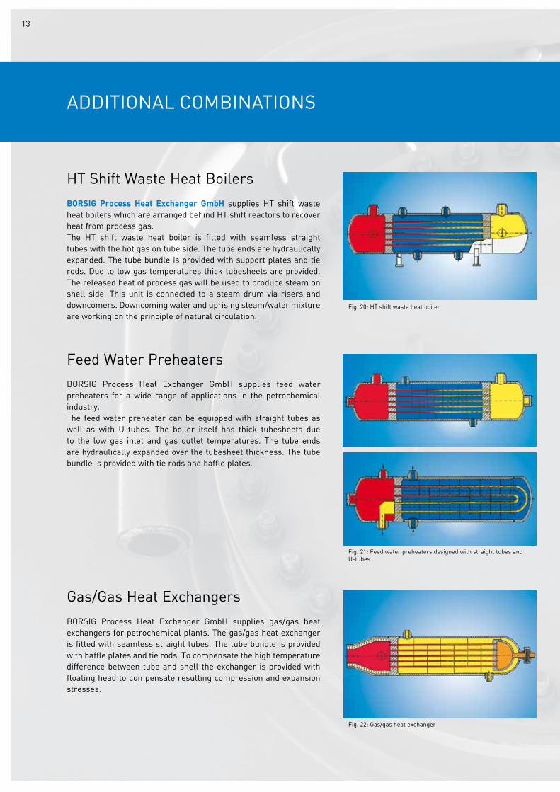
Fig. 20: HT shift waste heat boiler
HT Shift Waste Heat BoilersBORSIG Process Heat Exchanger GmbH supplies HT shift waste heat boilers which are arranged behind HT shift reactors to recover heat from process gas.The HT shift waste heat boiler is fitted with seamless straight tubes with the hot gas on tube side. The tube ends are hydraulically expanded. The tube bundle is provided with support plates and tie rods. Due to low gas temperatures thick tubesheets are provided. The released heat of process gas will be used to produce steam on shell side. This unit is connected to a steam drum via risers and downcomers. Downcoming water and uprising steam/water mixture are working on the principle of natural circulation.
Feed Water PreheatersBORSIG Process Heat Exchanger GmbH supplies feed water preheaters for a wide range of applications in the petrochemical industry.The feed water preheater can be equipped with straight tubes as well as with u-tubes. The boiler itself has thick tubesheets due to the low gas inlet and gas outlet temperatures. The tube ends are hydraulically expanded over the tubesheet thickness. The tube bundle is provided with tie rods and baffle plates.
Gas/Gas Heat ExchangersBORSIG Process Heat Exchanger GmbH supplies gas/gas heat exchangers for petrochemical plants. The gas/gas heat exchanger is fitted with seamless straight tubes. The tube bundle is provided with baffle plates and tie rods. To compensate the high temperature difference between tube and shell the exchanger is provided with floating head to compensate resulting compression and expansion stresses.
Fig. 21: Feed water preheaters designed with straight tubes and u-tubes
Fig. 22: Gas/gas heat exchanger
13
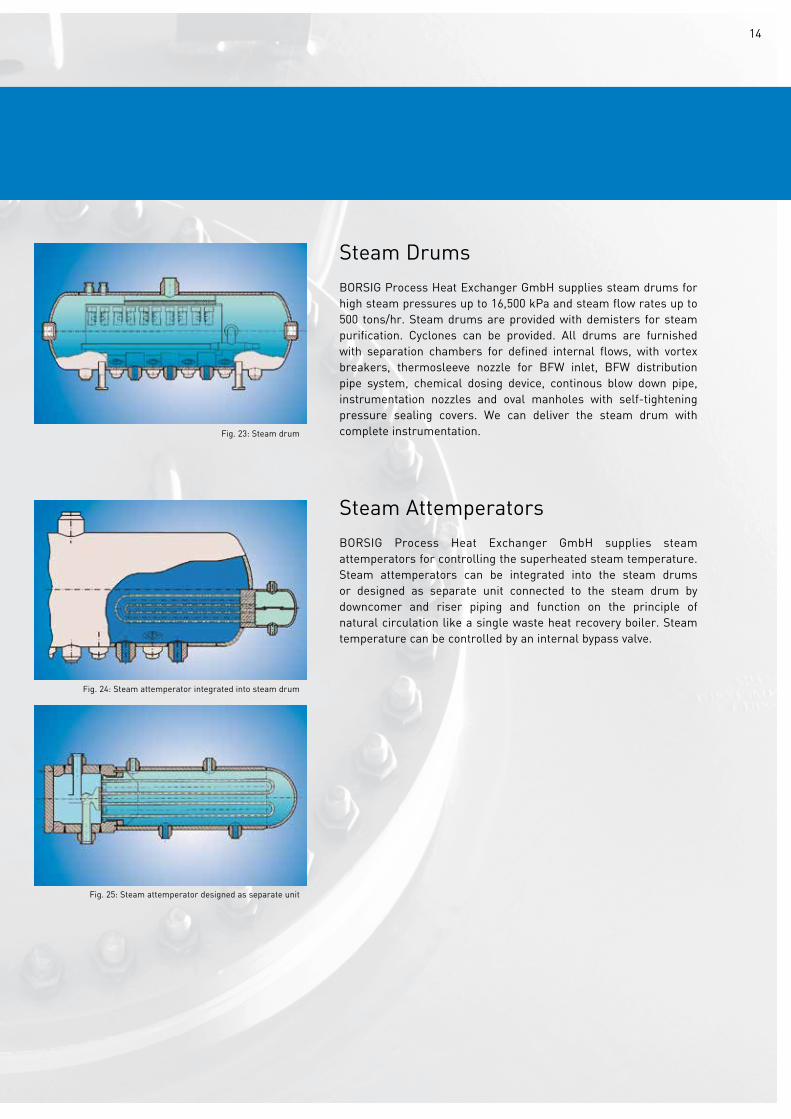
Steam DrumsBORSIG Process Heat Exchanger GmbH supplies steam drums for high steam pressures up to 16,500 kPa and steam flow rates up to 500 tons/hr. Steam drums are provided with demisters for steam purification. Cyclones can be provided. All drums are furnished with separation chambers for defined internal flows, with vortex breakers, thermosleeve nozzle for BFW inlet, BFW distribution pipe system, chemical dosing device, continous blow down pipe, instrumentation nozzles and oval manholes with self-tightening pressure sealing covers. We can deliver the steam drum with complete instrumentation.
Steam AttemperatorsBORSIG Process Heat Exchanger GmbH supplies steam attemperators for controlling the superheated steam temperature. Steam attemperators can be integrated into the steam drums or designed as separate unit connected to the steam drum by downcomer and riser piping and function on the principle of natural circulation like a single waste heat recovery boiler. Steam temperature can be controlled by an internal bypass valve.
Fig. 23: Steam drum
Fig. 24: Steam attemperator integrated into steam drum
Fig. 25: Steam attemperator designed as separate unit
14

MANuFACTuRING
BORSIG Process Heat Exchanger GmbH in Berlin owns more than 16,700 m² of indoor workshop facilities and is equipped with a 250 t crane capacity. High-tech welding technology is our core competence, such as the laser controlled welding seam guidance system for submerged narrow-gap welding, the use of robot welding systems for the GMAW welding process in the high pressure vessel manufacture, GMAW narrow gap robot systems with integrated 3D cutter systems plasma and autogenous, TIG hot wire welding, RES and SAW strip weld cladding, the automatic tube to tubesheet welding incl. inbore welding of up to 500 mm as well as qualified machining of all steel and nickel-based alloys.
The company has a direct water connection since 2008, the Borsig-Harbor, so that pressure vessels and heat exchangers of any overall size can be transported easily on the water way.
NDT teesting of stiffened stubesheet system
3D-plasma cutting
Machining of stiffened tubesheet system
MAG welding
15
Assembly of a compact unit
Robot welding
Compact unit ready for shipment
16
ENGINEERING
BORSIG Process Heat Exchanger GmbH has complete in-house engineering facilities. Thermal layout of heat exchangers and special heat transfer calculations are performed and checked with computer programs developed in-house. For highly complex tasks, the gas flow and heat transfer are calculated by means of three-dimensional CFD models (computational fluid dynamics).
The pressure vessels and heat exchangers are calculated with computer programs developed in-house and commercial software PROBAD or PvElite according to all national and international design standards:
ASME CODE Sections I and VIII (Div.1 & Div.2), ASME B31.1 and B31.3, AD-2000, TRD, EN 13445, PD 5500, CODAP, RTOD, IBR, JIS, Australian Standards, Russian Standards, China SQL and GB 150.
In the case of critical parts, Finite Element Analysis with software package ANSyS is carried out.
Flexibility, foundation loads and nozzle loads on interconnecting piping are calculated by software Rohr2 or CAESAR II.
BORSIG Process Heat Exchanger GmbH supplies also the service of complete replacement jobs of waste heat boilers in ammonia, methanol, hydrogen, ethylen and all other steam reforming plants. BORSIG supervisors are specialized on replacement performances covering the detailed engineering, elaborating the shortest time frame, determining the logistic replacement sequence, mobilization of local personnel and complete supervision from shut down to start-up of plant.
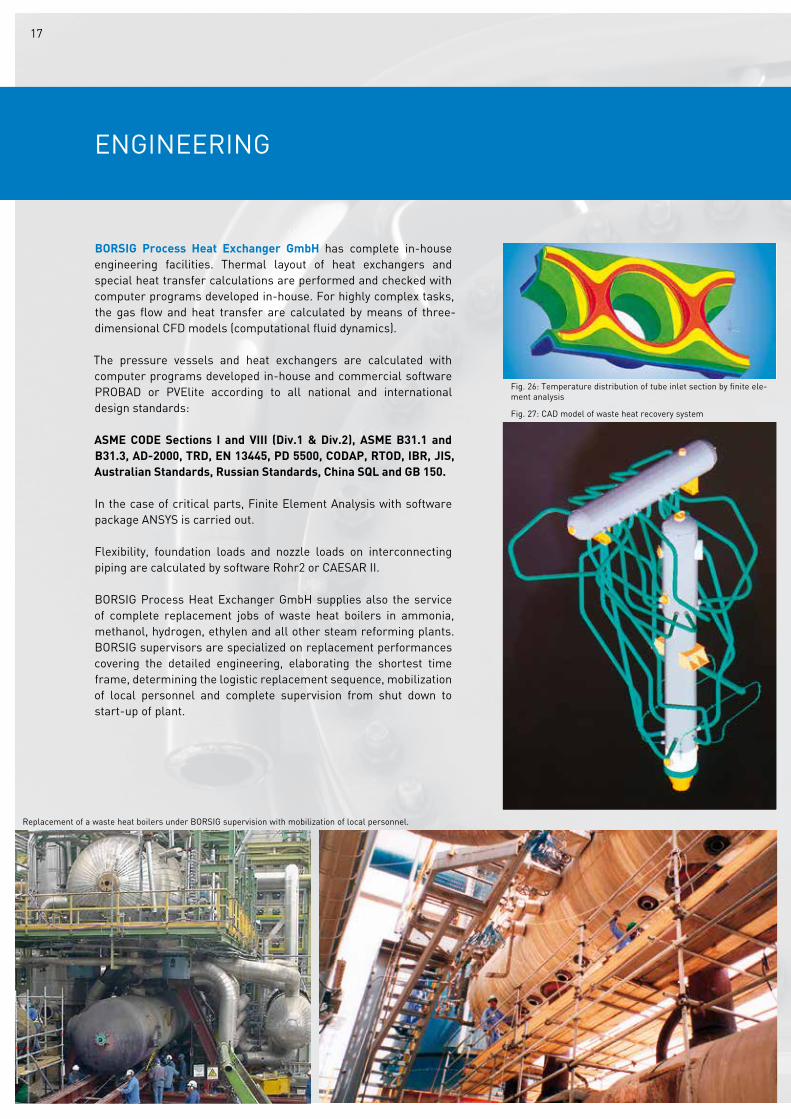
Fig. 26: Temperature distribution of tube inlet section by finite ele-ment analysis
Fig. 27: CAD model of waste heat recovery system
Replacement of a waste heat boilers under BORSIG supervision with mobilization of local personnel.
17
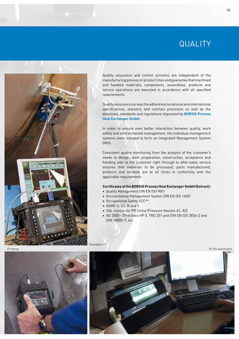
QuALITy
Quality assurance and control activities are independent of the manufacturing process or product lines and guarantee that machined and handled materials, components, assemblies, products and service operations are executed in accordance with all specified requirements.
Quality assurance surveys the adherence to national and international specifications, statutory and contract provisions as well as the directives, standards and regulations stipulated by BORSIG Process Heat Exchanger GmbH.
In order to ensure even better interaction between quality, work safety and environmental management, the individual management systems were merged to form an Integrated Management System (IMS).
Consistent quality monitoring from the analysis of the customer‘s needs to design, work preparation, construction, acceptance and handing over to the customer right through to after-sales service ensures that materials to be processed, parts manufactured, products and services are at all times in conformity with the applicable requirements
Certificates of the BORSIG Process Heat Exchanger GmbH (Extract):• Quality Management DIN EN ISO 9001• Environmental Management System DIN EN ISO 14001• Occupational Safety SCC**• ASME u, u2, R and S• SQL licence for PR China (Pressure vessels A1, A2)• AD 2000 - Directives HP 0, TRD 201 and DIN EN ISO 3834-2 and DIN 18800-7, etc.
Recordable uTuT testing RT film examination
18
BORSIG Process Heat Exchanger GmbHEgellsstraße 21 13507 Berlin / Germany
Phone +49 (0) 30 4301-01 Fax +49 (0) 30 4301-2447E-mail [email protected]
www.borsig.de/pro
BORSIG PROCESS HEAT EXCHANGER GMBH - 01/2019