boron fiber neutron shielding properties · boron fiber neutron shielding properties josephw....
TRANSCRIPT
BORON FIBER NEUTRON SHIELDING PROPERTIES
Joseph W. Hanafin, William Grant, Specialty Materials, Inc. Lowell, MA1
Leo Bobek, Thomas Regan, UMass Lowell, Radiation Laboratory, Lowell, MA2
January 10, 2011
Introduction
Boron fiber is a large diameter monofilament (102 micrometers, 4.0 mils) made via chemical vapor deposition by
Specialty Materials, Inc (SMI), Lowell, MA. Since its development in the early 1960s, it has been used in a wide range of
applications from aerospace to sporting goods because of its excellent mechanical properties, most notably its
extremely high compression strength. However, another important characteristic of elemental boron and boron fiber is
its ability to capture neutrons, which makes it effective for radiation shielding in the nuclear power industry and neutron
capture therapy in the medical industry. SMI collaborated with the U Mass Lowell (UML) Radiation Laboratory to
conduct a comparative study of the neutron shielding effectiveness of a number of boron composite configurations.
To better understand why boron fiber can be an effective tool for neutron shielding, it is worthwhile to step back and
look at the fundamental properties of elemental boron. Boron exists in nature primarily as borate oxides and salts such
as borax. The most common uses of boron are as a silicon dopant in the semiconductor industry, in sodium perborate
bleaches, and as an oxide in glasses and ceramics to improve their resistance to thermal shock. Boron can also be
formed into materials such as cubic boron nitride, an extremely hard abrasive that can scratch diamonds, and boron
carbide (B4C), also used as an industrial abrasive (Mohs Hardness of 9.5) and in ballistic ceramics.
Boron exists in two naturally occurring isotopes: 11B (80.1%) and 10B (19.9%). These isotopes can be separated naturally
during mineral recrystallization, and hydrothermal alteration of rock, which can result in the preferential removal of 10B(OH)4 ion onto clays and may explain the large 11B enrichment in sea water relative to the oceanic and continental
crusts, or through chemical means to give up to 99% enrichment of either isotope.
The 10B isotope is excellent at capturing thermal neutrons when combined as a carbide or oxide. As stated earlier it is
used in the nuclear power industry for neutron radiation shielding, and in the medical industry in neutron capture
therapy.
In nuclear reactors, un‐enriched boron, in the form of boric acid, dissolved in the cooling and containment waters is used
as an acid buffer and to control the neutron flux in newly refueled reactors.
Deep space exploration will require spacecraft that can shield its occupants from a range of radiation including cosmic,
gamma and neutron radiation, so boron containing fillers could play a role as a neutron shielding material. Boron fiber
may play a role in these spacecrafts as both a structural reinforcement and as a neutron shield.
1. Specialty Materials, Inc. 1449 Middlesex Street, Lowell, MA 01851
2. Radiation Laboratory, University of Massachusetts Lowell, Pinanski Building, Room 106, 1 University Avenue, Lowell, MA 01854
Case Study
The following work was undertaken to evaluate the comparative shielding effectiveness of boron fiber, boron
nanopowder, and enriched 10boron carbide (10B4C) in various combinations, configurations and thicknesses, dispersed or
embedded into a high temperature thermoset epoxy resin.
Both the boron fiber and boron nanopowder are manufactured by Specialty Materials, Inc. of Lowell, Mass. Boron Fiber
is manufactured by a chemical vapor deposition process. Production grade boron fiber (102 micron, 4.0 mil) was used to
prepare all boron fiber containing samples used in this work. The fiber preform used to generate composite samples
was a 0.25” wide Boron Prepreg Tape consisting of 50 vol.% Boron fiber in a 3500F cure Type 5505 epoxy resin with 208
fibers per inch (fpi) and 0.005 inch ply thickness. Type 5505 is a proprietary formulation developed over thirty years ago
as a highly cross linked, thermally stable 350oF cure system. The resin system is solvent free and DICY cured. It is
specified for many military and commercial applications and has a long history of successful use in structural
composites.
Boron Nanopowder is being produced in pilot product scale via RF plasma processing, and is primarily intended to be
reacted with magnesium for use in MgB2 superconducting wire applications. The nanopowder material used in this
study had a median particle size of ~65 nm. The nanopowder boron is cocoa brown in color and dispersed readily into
the heated (70°C) 5505 epoxy resin using high speed mixing with a Flacktec SpeedMixer, or a Cowles type dispersion
blade.
The 10B4C is a product of Ceradyne, Inc. of Quapaw, OK. It is enriched with up to 99% 10B. Normal B4C shows a neutron
absorption probability of 760 Barn at a neutron velocity of 2200 m/sec, while this enriched Boron Carbide displays a
neutron absorption probability of 3800 Barn at a neutron velocity of 2200 m/sec.
Sample Preparation
Material samples were prepared in two different formats; small format coupons that were approximately 1” x 2” and
larger format coupons approximately 2” x 8”. Sample thickness varied with the fiber loading and material composition.
Those measurements are listed in Table 1.
TABLE 1: BORON SAMPLES FOR SHIELDING STUDY
Sample Resin B Fiber (Y/N)
Filler‐B4C or η B Powder
Plies Orientation (0/90) Sample Size (L X W X H, cm)
1 5505 Y None 8 0/0 20.4 x 5.1 x 0.11 2 5505 Y None 14 0/0 20.4 x 5.1 x 0.21 3 5505 Y None 8 0/90 5.1 x 2.54 x 0.11 4 5505 Y None 14 0/90 5.1 x 2.54 x 0.20 5 5505 Y None 48 0/0 5.1 x 2.54 x 0.69 6 5505 Y None 48 0/90 5.1 x 2.54 x 0.66 7 5505 Y B4C – 10% 7 0/0 19.6 x 4.8 x 0.10 8 5505 Y B4C – 10% 14 0/0 19.6 x 4.8 x 0.19 9 5505 Y B4C – 10% 14 0/90 5.1 x 2.5 x 0.20 10 5505 N None 1 NEAT RESIN 5.1 x 2.5 x 0.51 11 5505 N ηB – 5% 1 NEAT RESIN 23.0 x 5.1 x 0.62 12 5505 N B4C – 10% 1 NEAT RESIN 24.1 x 5.0 x 0.50 13 5505 N ηB – 5% 1 NEAT RESIN 10.0 x 10.0x0.55 14 5505 N B4C – 10% 1 NEAT RESIN 10.0 x 10.3x0.53 15 5505 N B4C – 20% 1 NEAT RESIN 5.0 x 2.5 x 0.60
Using these basic elements, a series of samples were prepared and exposed to a neutron source at the University of
Massachusetts at Lowell Radiation Laboratory to determine the neutron absorption and shielding properties of the neat
resin, resin filled with boron nanopowder, or enriched 10B4C, and resin containing either of those fillers and boron fibers,
fabricated into composites of varying thickness and fiber orientation.
Neutron Radiography System The UMass Lowell (UML) Research Reactor provides neutron fluences on the order of 1E6 neutron / cm2 at the sample analysis station on the thermal neutron radiography beam line. The beam line is approximately 20 feet long and evacuated for the majority of its length. A two inch aperture produces an L/D ratio for the beam line of approximately 120. The thermal neutron component of the neutron beam at the experimental station is highly thermalized with little measureable epithermal or fast neutron content. This is well suited for the analysis of the attenuation properties of materials. The neutron radiography process works on the attenuation principles described below where: .
Io = the unperturbed neutron beam intensity I = the beam intensity after passing through the absorber n = number of target nuclei σ = the microscopic neutron cross section
Variations in neutron attenuation by the target materials perturb a relative flat profiled neutron beam. The perturbed
neutron beam is then converted into optical light using a 100 micron thick Li:F ZnSCuAlAU converter screen. An Apogee
Alta CCD camera views the converter screen to gather optical signal, which forms the radiographic image. The CCD is a 1
Megapixel Kodak 1001E with 16 bit resolution, which produces images with 56,000 different grayscale levels.
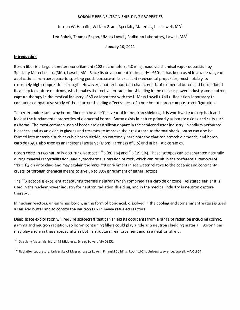
The Neutron Radiography Imaging Station is pictured in Figure 1. The Evacuated beam line is in the lower left side of the
image, while the camera (offset at 90 deg. from beam line) is seen on the right side of the image.
Figure 1. Neutron Radiography Imaging Station with samples 1, 2, 7, 8
The samples were arranged to be perpendicular to the neutron beam. Samples were exposed to approximately 2E8
neutrons/cm2 for each image that was generated. Based on the size of the CCD pixels (26 microns) and size of the active
imaging area (8” x 8”), the spatial resolution of all images is approximately 200 microns. In order to produce high quality
images, multiple sequential images were taken of several sample sets. This allowed for 8 low resolution images to be
combined into a single higher image. The images were then filtered using a 3x3 median kernel filter to remove hot or
cold pixel spots in the image.
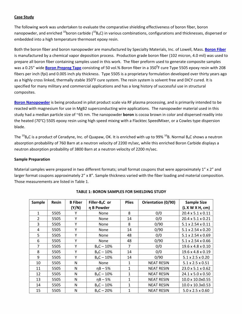
Image Results
The first images that were analyzed are pictured below. This picture is of the samples as they were positioned in the
UML thermal neutron beam line. There samples are ordered 1, 2, 7 and 8 in this series of neutron images.
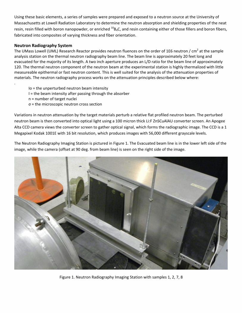
Samples 1, 2, 7, 8 were all prepared by placing strips of 0.25 inch wide Boron fiber/5505 resin tape side by side to build
up to a 2 inch wide tape. Samples 1 and 7 were prepared from seven or eight (7 or 8) plies, respectively, of this tape with
all boron fiber running in the same direction ‐ (O/O alignment). The radiographs clearly show the gaps between the
individual 0.25 inch strips as areas of lower neutron absorption. Striations in samples 1 and 7 are likely a product of the
tape misalignment and lack of overlapping neutron absorbers. This resulted in a partial transmission of the neutron
beam through the samples.
Figure 2. Optical Image of parts 1, 2, 7 and 8
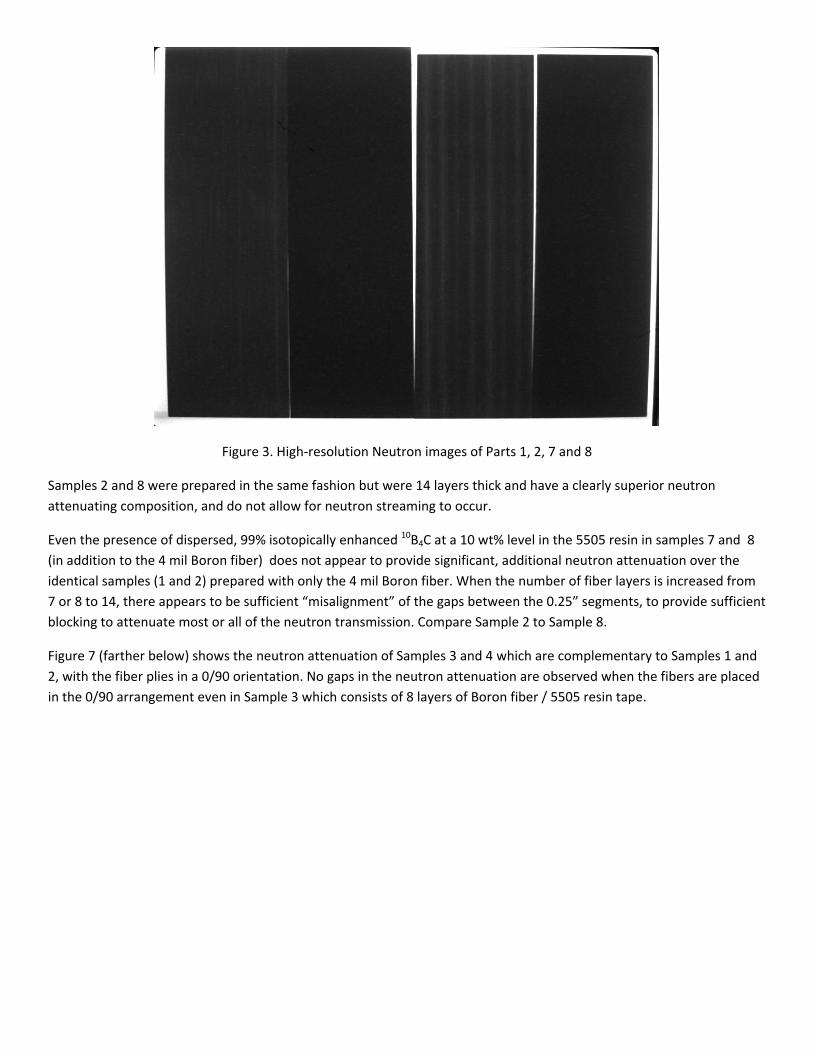
Figure 3. High‐resolution Neutron images of Parts 1, 2, 7 and 8
Samples 2 and 8 were prepared in the same fashion but were 14 layers thick and have a clearly superior neutron
attenuating composition, and do not allow for neutron streaming to occur.
Even the presence of dispersed, 99% isotopically enhanced 10B4C at a 10 wt% level in the 5505 resin in samples 7 and 8
(in addition to the 4 mil Boron fiber) does not appear to provide significant, additional neutron attenuation over the
identical samples (1 and 2) prepared with only the 4 mil Boron fiber. When the number of fiber layers is increased from
7 or 8 to 14, there appears to be sufficient “misalignment” of the gaps between the 0.25” segments, to provide sufficient
blocking to attenuate most or all of the neutron transmission. Compare Sample 2 to Sample 8.
Figure 7 (farther below) shows the neutron attenuation of Samples 3 and 4 which are complementary to Samples 1 and
2, with the fiber plies in a 0/90 orientation. No gaps in the neutron attenuation are observed when the fibers are placed
in the 0/90 arrangement even in Sample 3 which consists of 8 layers of Boron fiber / 5505 resin tape.
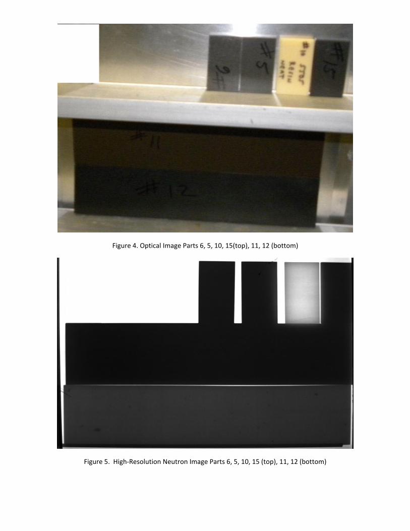
Figure 4. Optical Image Parts 6, 5, 10, 15(top), 11, 12 (bottom)
Figure 5. High‐Resolution Neutron Image Parts 6, 5, 10, 15 (top), 11, 12 (bottom)
Effect of Neutron Attenuating Fillers on neat 5505 Resin
Figures 4 and 5 display the optical and high resolution Neutron images of 6 different samples.
Sample 10, neat 5505 resin at a 5 mm thickness is, as expected, essentially neutron transparent.
Sample 11, neat 5505 resin at 5 mm thickness, with 5 wt% added nano‐Boron shows improved attenuation over the neat
resin and slightly less than the following Sample 12, containing 10 wt% of the 10B isotopically enriched B4C. The
absorption increases again in Sample 15 as the concentration of 10B isotopically enriched B4C increases from 10 to 20
wt%.
Samples 5 and 6, with 5505 resin and only 4 mil Boron fiber at 48 plies in either the 0/0 or alternating 0/90 orientation
display excellent attenuation that is not affected by the orientation of the plies.
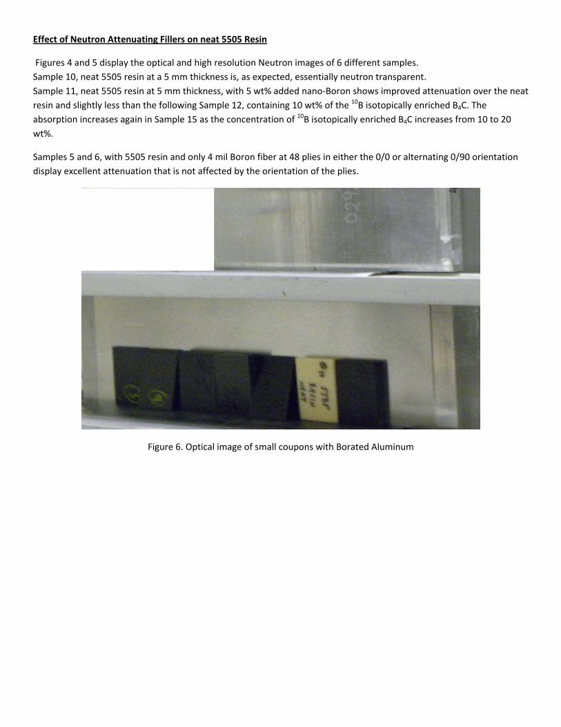
Figure 6. Optical image of small coupons with Borated Aluminum
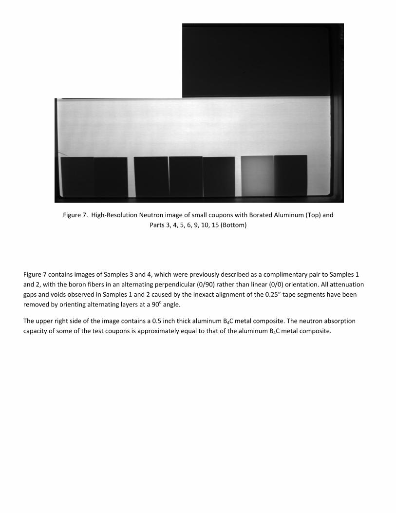
Figure 7. High‐Resolution Neutron image of small coupons with Borated Aluminum (Top) and
Parts 3, 4, 5, 6, 9, 10, 15 (Bottom)
Figure 7 contains images of Samples 3 and 4, which were previously described as a complimentary pair to Samples 1
and 2, with the boron fibers in an alternating perpendicular (0/90) rather than linear (0/0) orientation. All attenuation
gaps and voids observed in Samples 1 and 2 caused by the inexact alignment of the 0.25” tape segments have been
removed by orienting alternating layers at a 90o angle.
The upper right side of the image contains a 0.5 inch thick aluminum B4C metal composite. The neutron absorption
capacity of some of the test coupons is approximately equal to that of the aluminum B4C metal composite.
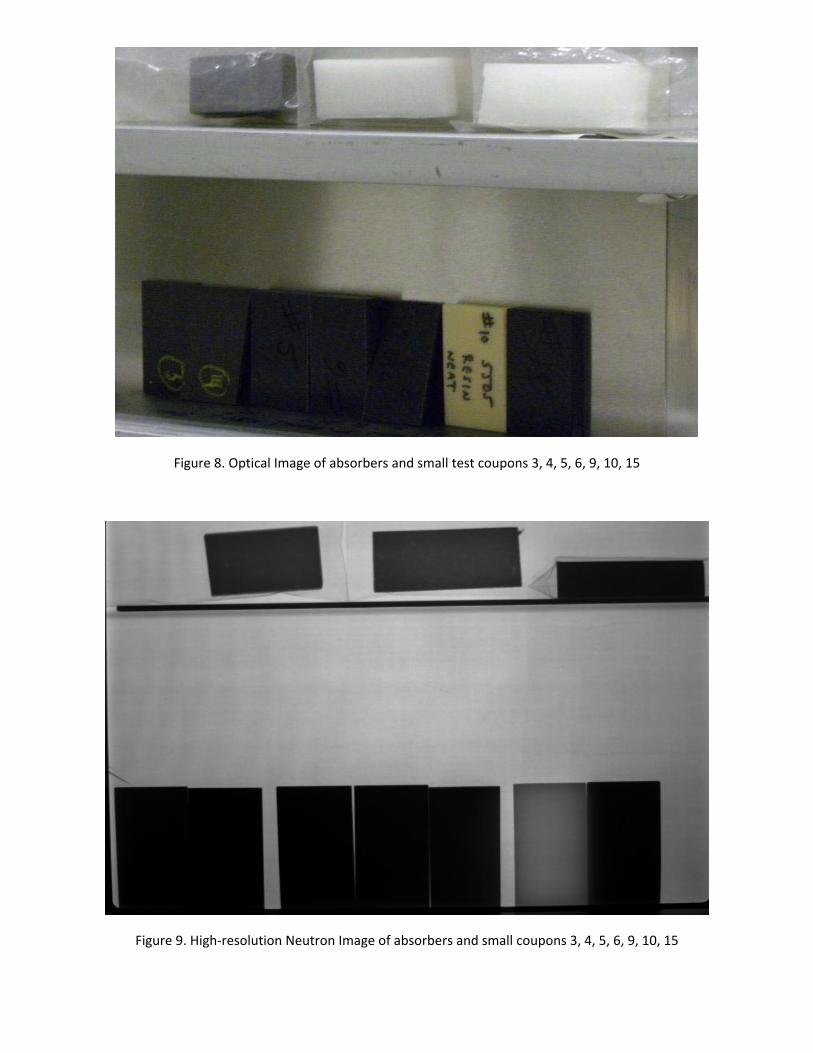
Figure 8. Optical Image of absorbers and small test coupons 3, 4, 5, 6, 9, 10, 15
Figure 9. High‐resolution Neutron Image of absorbers and small coupons 3, 4, 5, 6, 9, 10, 15
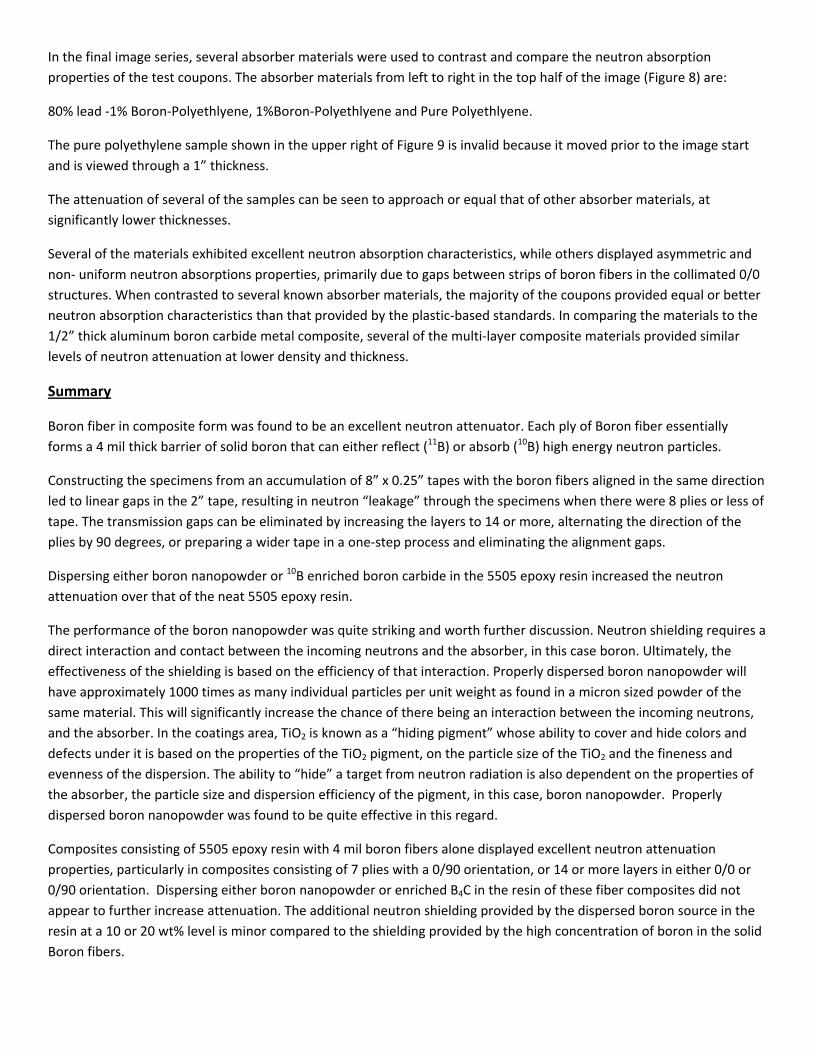
In the final image series, several absorber materials were used to contrast and compare the neutron absorption
properties of the test coupons. The absorber materials from left to right in the top half of the image (Figure 8) are:
80% lead ‐1% Boron‐Polyethlyene, 1%Boron‐Polyethlyene and Pure Polyethlyene.
The pure polyethylene sample shown in the upper right of Figure 9 is invalid because it moved prior to the image start
and is viewed through a 1” thickness.
The attenuation of several of the samples can be seen to approach or equal that of other absorber materials, at
significantly lower thicknesses.
Several of the materials exhibited excellent neutron absorption characteristics, while others displayed asymmetric and
non‐ uniform neutron absorptions properties, primarily due to gaps between strips of boron fibers in the collimated 0/0
structures. When contrasted to several known absorber materials, the majority of the coupons provided equal or better
neutron absorption characteristics than that provided by the plastic‐based standards. In comparing the materials to the
1/2” thick aluminum boron carbide metal composite, several of the multi‐layer composite materials provided similar
levels of neutron attenuation at lower density and thickness.
Summary
Boron fiber in composite form was found to be an excellent neutron attenuator. Each ply of Boron fiber essentially
forms a 4 mil thick barrier of solid boron that can either reflect (11B) or absorb (10B) high energy neutron particles.
Constructing the specimens from an accumulation of 8” x 0.25” tapes with the boron fibers aligned in the same direction
led to linear gaps in the 2” tape, resulting in neutron “leakage” through the specimens when there were 8 plies or less of
tape. The transmission gaps can be eliminated by increasing the layers to 14 or more, alternating the direction of the
plies by 90 degrees, or preparing a wider tape in a one‐step process and eliminating the alignment gaps.
Dispersing either boron nanopowder or 10B enriched boron carbide in the 5505 epoxy resin increased the neutron
attenuation over that of the neat 5505 epoxy resin.
The performance of the boron nanopowder was quite striking and worth further discussion. Neutron shielding requires a
direct interaction and contact between the incoming neutrons and the absorber, in this case boron. Ultimately, the
effectiveness of the shielding is based on the efficiency of that interaction. Properly dispersed boron nanopowder will
have approximately 1000 times as many individual particles per unit weight as found in a micron sized powder of the
same material. This will significantly increase the chance of there being an interaction between the incoming neutrons,
and the absorber. In the coatings area, TiO2 is known as a “hiding pigment” whose ability to cover and hide colors and
defects under it is based on the properties of the TiO2 pigment, on the particle size of the TiO2 and the fineness and
evenness of the dispersion. The ability to “hide” a target from neutron radiation is also dependent on the properties of
the absorber, the particle size and dispersion efficiency of the pigment, in this case, boron nanopowder. Properly
dispersed boron nanopowder was found to be quite effective in this regard.
Composites consisting of 5505 epoxy resin with 4 mil boron fibers alone displayed excellent neutron attenuation
properties, particularly in composites consisting of 7 plies with a 0/90 orientation, or 14 or more layers in either 0/0 or
0/90 orientation. Dispersing either boron nanopowder or enriched B4C in the resin of these fiber composites did not
appear to further increase attenuation. The additional neutron shielding provided by the dispersed boron source in the
resin at a 10 or 20 wt% level is minor compared to the shielding provided by the high concentration of boron in the solid
Boron fibers.
The analysis performed under this study provides a relative contrast of the Specialty Materials test coupons to absorb
and attenuate thermal neutrons. The images were taken with 16 bit resolution, providing a significant number of gray
levels. All of these levels are not visible or easily contrasted in the standard JPEG format. Commercial image viewers that
provide for shifting the gray scale area of interest (thus allowing for the image files to be viewed in their full digital
context) are required to view the digital depth of the images.
Future work will focus on quantifying the neutron absorption properties of several of the composites tested in this
study, and determining the effect of long term exposure to neutron and gamma radiation on the physical and
mechanical properties of the composite resin binders.
Acknowledgements:
The authors wish to thank Richard Ruediger of Specialty Materials, Inc. who prepared the many samples used in this
study.
They also wish to thank Al Kumnick, Technical Director at Specialty Materials, Inc for his many insightful and helpful
suggestions and recommendations throughout this work.