booster pump kits - · pdf filerev 04-07-2009 booster pump kits installation manual warning...
TRANSCRIPT
REV 04-07-2009
Booster Pump Kits
INSTALLATION MANUALWARNING
Please read carefully before proceeding with installation. Failure to follow any attached instructions or operating parameter may lead to
the product’s failure and possible damage to property.
SpectraPure
SpectraPure®Inc. 480.894.5437 Call us toll-free 1.800.685.2783 2167 East Fifth St, Tempe, Arizona 85281
®
2
No part of this publication may be reproduced, stored in a retrieval system, or transmitted in any form or by any means, electronic, mechanical, photocopying, recording or otherwise without the prior written permission of SpectraPure Inc.
COPYRIGHT© 2009 BY SPECTRAPURE INCALL RIGHTS RESERVED
TABLE OF CONTENTSPump Specifications...................................................................................................................2-3
Installation
Installation of Booster Pump........................................................................................4-5
Liquid Level Controlled Pump......................................................................................6-8
Pressure Operated Booster Pump............................................................................9-12
Troubleshooting Guide
Mounting & Troubleshooting info........................................................................13-14
Warranty............................................................................................................................15
Replacement Parts......................................................................................................................16
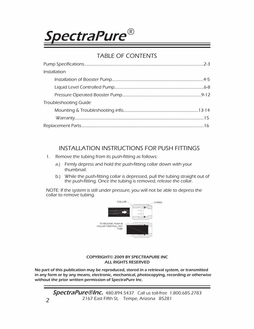
INSTALLATION INSTRUCTIONS FOR PUSH FITTINGS1. Remove the tubing from its push-fitting as follows:
a.) Firmly depress and hold the push-fitting collar down with your thumbnail.
b.) While the push-fitting collar is depressed, pull the tubing straight out of the push-fitting. Once the tubing is removed, release the collar.
NOTE: If the system is still under pressure, you will not be able to depress the collar to remove tubing.
SpectraPure®Inc. Fax 480.894.6109 Fax us toll-free 1.877.527.7873E-mail: [email protected] Visit us on the web www.spectrapure.com 3
SpectraPure ®
CAUTION:
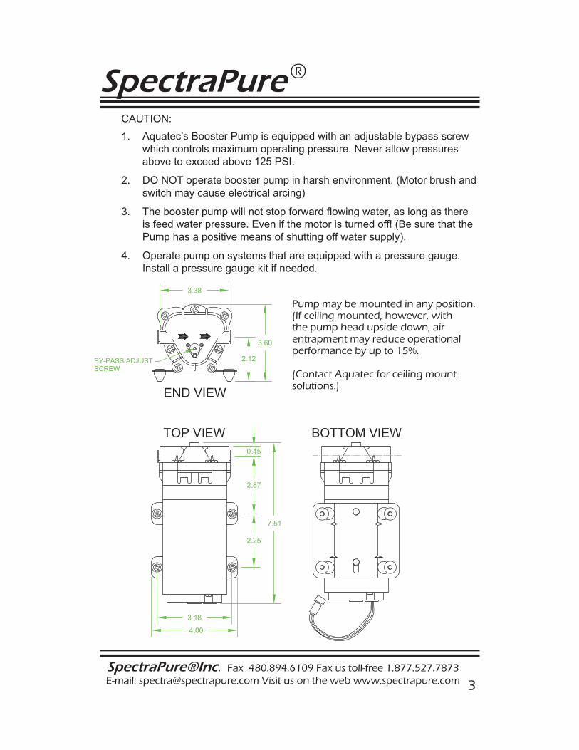
1. Aquatec’s Booster Pump is equipped with an adjustable bypass screw which controls maximum operating pressure. Never allow pressures above to exceed above 125 PSI.
2. DO NOT operate booster pump in harsh environment. (Motor brush and switch may cause electrical arcing)
3. The booster pump will not stop forward fl owing water, as long as there is feed water pressure. Even if the motor is turned off! (Be sure that the Pump has a positive means of shutting off water supply).
4. Operate pump on systems that are equipped with a pressure gauge. Install a pressure gauge kit if needed.
Pump may be mounted in any position. (If ceiling mounted, however, with the pump head upside down, air entrapment may reduce operational performance by up to 15%.
(Contact Aquatec for ceiling mount solutions.)
SpectraPure
SpectraPure®Inc. 480.894.5437 Call us toll-free 1.800.685.2783 2167 East Fifth St, Tempe, Arizona 85281
®
4
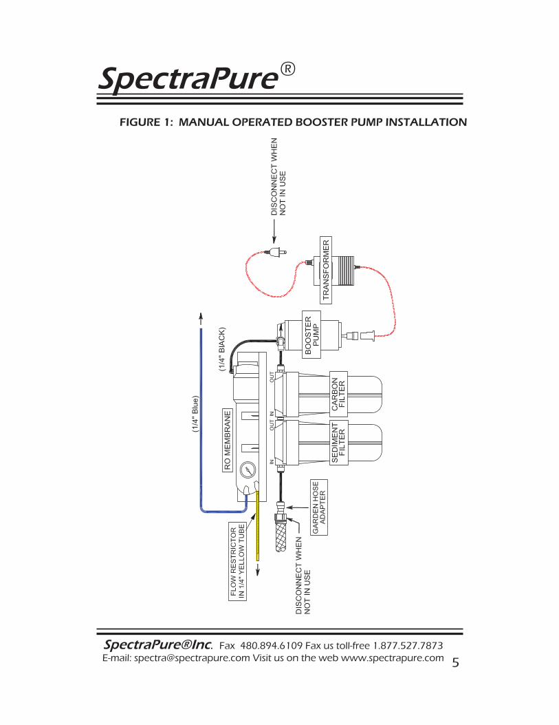
INSTALLATION INSTRUCTIONS FOR BPLF & BPHF (Booster Pump Kit for Manual Use Only)
1. Refer to Figure 1.
2. The pump should be installed on the input line to the RO Membrane at any convenient location, and may be mounted in any direction (horizontal or vertical). The distance between the input of the pump and the water supply connection should be limited to 20 feet, if the water source is less than 30 psi. For greater distances or lower pressure, increase the tubing diameter from the water source.
NOTE: The water supply plumbing fitting should be a minimum of 1/4”. Do not use a piercing valve for this connection.
3. Locate the pump and note the flow direction arrow on the front of the pump head. When making the plumbing connections to the pump head be sure that the water flow corresponds with this arrow.
4. Mount the pump in relation to the RO System as indicated in figure 1. Cut the black tube where convenient. Use the pump to reconnect the two cut ends.
5. Check all the fittings and turn water supply on.
6. Locate the male connector on the power cord of the booster pump and plug it into the female connector on the transformer. Plug the transformer into your AC receptacle.
7. The recommended operating pressure is 80 psi. If the pressure is over 80 psi, adjust the pump by inserting a 1/16 . inch Allen head wrench into the set screw on the front of the pump head. Turn it clockwise to increase the pressure or counterclockwise to decrease the pressure. The pump pressure will change in accordance with variations in incoming water pressure.
THIS COMPLETES THE INSTALLATION.
Note: The input and output tubing attached to the booster pump will vibrate, this is considered normal.
SpectraPure®Inc. Fax 480.894.6109 Fax us toll-free 1.877.527.7873E-mail: [email protected] Visit us on the web www.spectrapure.com 5
SpectraPure ®
FIGURE 1: MANUAL OPERATED BOOSTER PUMP INSTALLATION
SpectraPure
SpectraPure®Inc. 480.894.5437 Call us toll-free 1.800.685.2783 2167 East Fifth St, Tempe, Arizona 85281
®
6
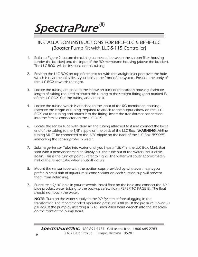
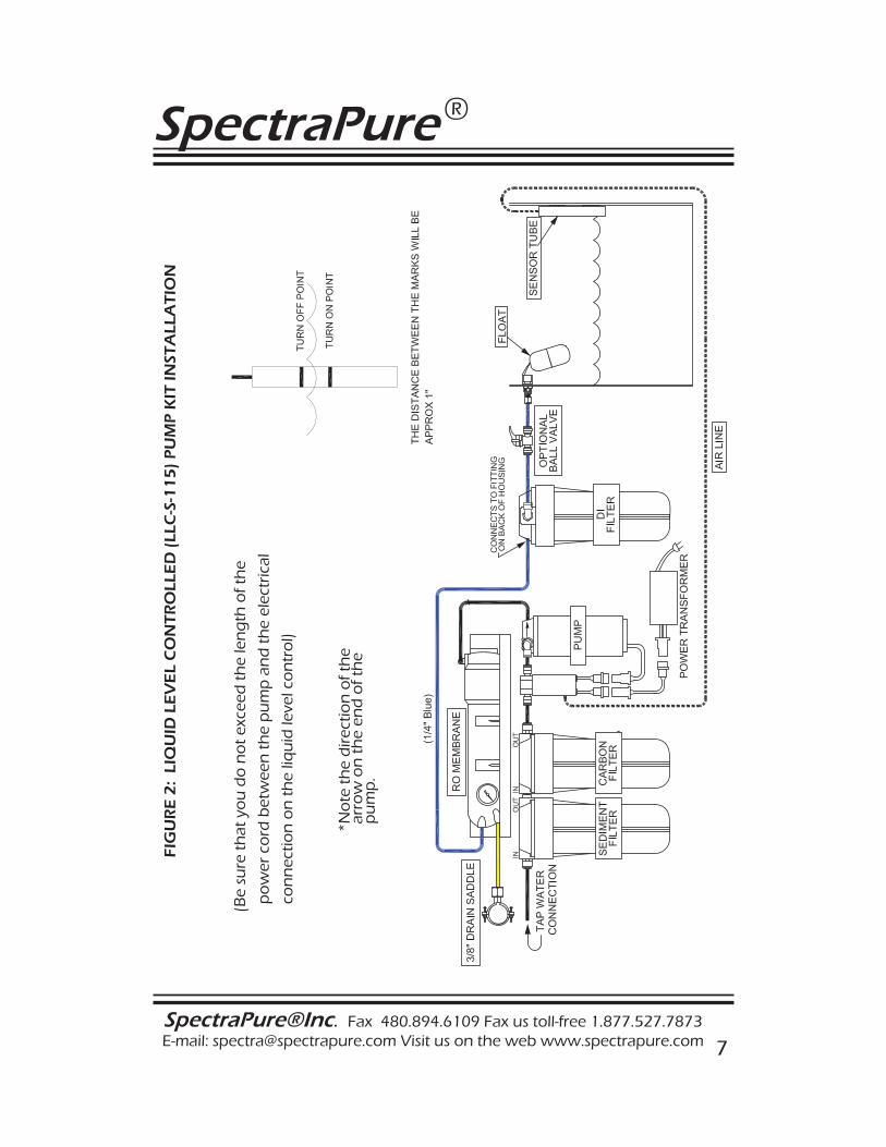
1. Refer to Figure 2. Locate the tubing connected between the carbon filter housing (under the bracket) and the input of the RO membrane housing (above the bracket). The LLC BOX will be installed on this tubing.
2. Position the LLC BOX on top of the bracket with the straight inlet port over the hole which is near the left side as you look at the front of the system. Position the body of the LLC BOX towards the right.
3. Locate the tubing attached to the elbow on back of the carbon housing. Estimate length of tubing required to attach this tubing to the straight fitting (port marked IN) of the LLC BOX. Cut the tubing and attach it.
4. Locate the tubing which is attached to the input of the RO membrane housing. Estimate the length of tubing required to attach to the output elbow on the LLC BOX, cut the tubing and attach it to the fitting. Insert the transformer connection into the female connector on the LLC BOX.
6. Locate the sensor tube with clear air line tubing attached to it and connect the loose end of the tubing to the 1/8” nipple on the back of the LLC Box. WARNING: Airline tubing MUST be connected to the 1/8” nipple on the back of the LLC Box BEFORE immersing the sensor probe in water.
7. Submerge Sensor Tube into water until you hear a “click” in the LLC Box. Mark that spot with a permanent marker. Slowly pull the tube out of the water until it clicks again. This is the turn off point. (Refer to Fig 2). The water will cover approximately half of the sensor tube when shut-off occurs.
8. Mount the sensor tube with the suction cups provided by whatever means you prefer. A small dab of aquarium silicone sealant on each suction cup will prevent them from detaching.
7. Puncture a 9/16” hole in your reservoir. Install float on the hole and connect the 1/4” blue product water tubing to the back-up safety float (REFER TO PAGE 8). The float should not touch the water.
NOTE: Turn on the water supply to the RO System before plugging in the transformer. The recommended operating pressure is 80 psi. If the pressure is over 80 psi, adjust the pump by inserting a 1/16 . inch Allen head wrench into the set screw on the front of the pump head
INSTALLATION INSTRUCTIONS FOR BPLF-LLC & BPHF-LLC (Booster Pump Kit with LLC-S-115 Controller)
SpectraPure®Inc. Fax 480.894.6109 Fax us toll-free 1.877.527.7873E-mail: [email protected] Visit us on the web www.spectrapure.com 7
SpectraPure ®
FIG
UR
E 2
: LI
QU
ID L
EV
EL
CO
NT
RO
LLE
D (
LLC
-S-1
15
) P
UM
P K
IT IN
STA
LLA
TIO
N
(Be
sure
th
at y
ou
do
no
t ex
ceed
th
e le
ng
th o
f th
e
po
wer
co
rd b
etw
een
th
e p
um
p a
nd
th
e el
ectr
ical
con
nec
tion
on
th
e liq
uid
leve
l co
ntr
ol)
*No
te t
he
dir
ectio
n o
f th
e ar
row
on
th
e en
d o
f th
e p
um
p.
*
SpectraPure
SpectraPure®Inc. 480.894.5437 Call us toll-free 1.800.685.2783 2167 East Fifth St, Tempe, Arizona 85281
®
8
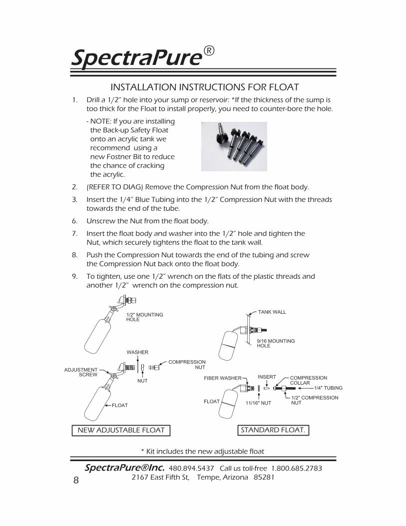
INSTALLATION INSTRUCTIONS FOR FLOAT1. Drill a 1/2” hole into your sump or reservoir: *If the thickness of the sump is too thick for the Float to install properly, you need to counter-bore the hole.
- NOTE: If you are installing the Back-up Safety Float onto an acrylic tank we recommend using a new Fostner Bit to reduce the chance of cracking the acrylic.
2. (REFER TO DIAG) Remove the Compression Nut from the float body.
3. Insert the 1/4” Blue Tubing into the 1/2” Compression Nut with the threads towards the end of the tube.
6. Unscrew the Nut from the float body.
7. Insert the float body and washer into the 1/2” hole and tighten the Nut, which securely tightens the float to the tank wall.
8. Push the Compression Nut towards the end of the tubing and screw the Compression Nut back onto the float body.
9. To tighten, use one 1/2” wrench on the flats of the plastic threads and another 1/2” wrench on the compression nut.
NEW ADJUSTABLE FLOAT STANDARD FLOAT.
* Kit includes the new adjustable float
SpectraPure®Inc. Fax 480.894.6109 Fax us toll-free 1.877.527.7873E-mail: [email protected] Visit us on the web www.spectrapure.com 9
SpectraPure ®
INSTALLATION INSTRUCTIONS FOR BPLF-PS & BPHF-PS (Booster Pump Kit with Pressure Switch Control)
This installation is most often used with systems that already contain the Auto Shut-Off Valve (ASO), or some other device that turns the system on and off. If your system has an ASO valve, replace it with the solenoid and pressure switch (As shown in figure 3).
1. Locate the tubing that connects to the RO membrane housing input.2. The Solenoid will be installed in this line along with the pump.3. Cut this line as it leaves the Carbon Pre-Filter. Attach the “IN” port of the solenoid to the line coming from the Carbon Filter.4. Mount the Booster Pump nearby. Run a length of 1/4” tubing from the output side of the solenoid to the input side of the Booster Pump. (Note the arrow on the pumps head for proper orientation. The arrow should point “down-stream”).5. Run another length of 1/4” tubing from the output of the Booster Pump to the input of the membrane housing.6. The wiring assembly that is attached to the pressure switch has male (pins) and female (holes) connectors. Connect the power supply to the male connector. Then, connect the female connector to the “Y” adapter.7. The “Y” adapter will then connect the Solenoid and the Booster Pump together.8. Check for leaks.
The recommended operating pressure is 80 psi. If the pressure is over 80 psi, adjust the pump by inserting a 1/16 . inch Allen head wrench into the set screw on the front of the pump head.
SpectraPure
SpectraPure®Inc. 480.894.5437 Call us toll-free 1.800.685.2783 2167 East Fifth St, Tempe, Arizona 85281
®
10
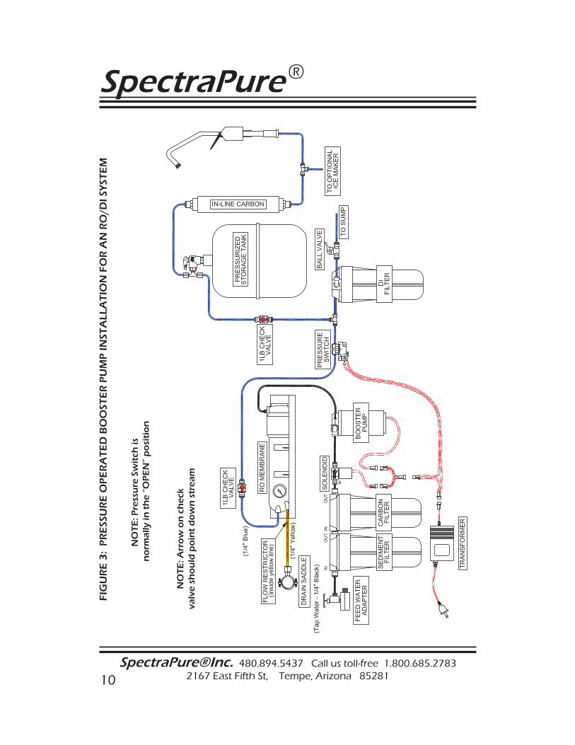
FIG
UR
E 3
: P
RE
SSU
RE
OP
ER
AT
ED
BO
OST
ER
PU
MP
INST
ALL
AT
ION
FO
R A
N R
O/D
I SY
STE
M
NO
TE
: Pre
ssu
re S
wit
ch is
no
rmal
ly in
th
e “O
PE
N”
po
siti
on
NO
TE
: Arr
ow
on
ch
eck
valv
e sh
ou
ld p
oin
t d
ow
n s
trea
m
SpectraPure®Inc. Fax 480.894.6109 Fax us toll-free 1.877.527.7873E-mail: [email protected] Visit us on the web www.spectrapure.com 11
SpectraPure ®
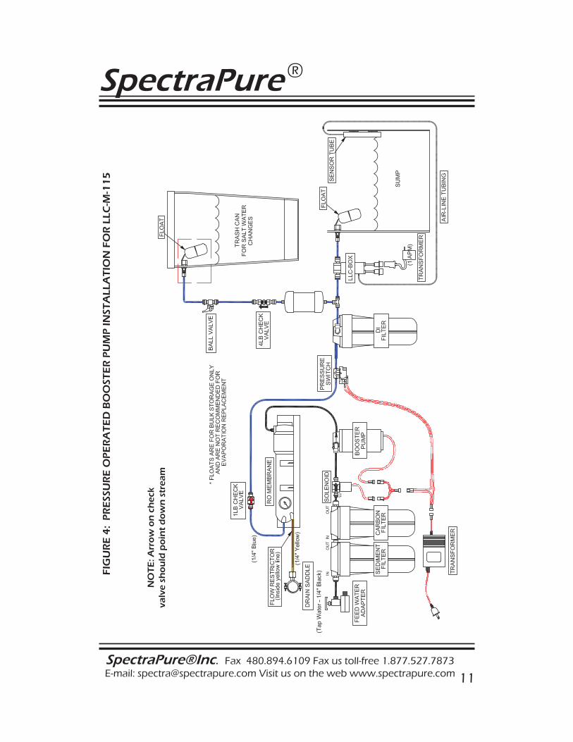
FIG
UR
E 4
: P
RE
SSU
RE
OP
ER
AT
ED
BO
OST
ER
PU
MP
INST
ALL
AT
ION
FO
R L
LC-M
-11
5
NO
TE
: Arr
ow
on
ch
eck
valv
e sh
ou
ld p
oin
t d
ow
n s
trea
m
SpectraPure
SpectraPure®Inc. 480.894.5437 Call us toll-free 1.800.685.2783 2167 East Fifth St, Tempe, Arizona 85281
®
12
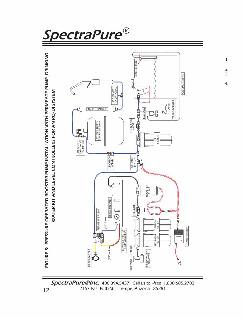
FIG
UR
E 5
: P
RE
SSU
RE
OP
ER
AT
ED
BO
OST
ER
PU
MP
INST
ALL
AT
ION
WIT
H P
ER
ME
AT
E P
UM
P, D
RIN
KIN
G
WA
TE
R K
IT A
ND
LE
VE
L C
ON
TR
OLL
ER
S FO
R A
N R
O/D
I SY
STE
M
1 2.3. 4.
SpectraPure®Inc. Fax 480.894.6109 Fax us toll-free 1.877.527.7873E-mail: [email protected] Visit us on the web www.spectrapure.com 13
SpectraPure ®
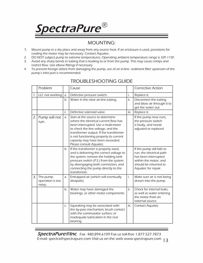
MOUNTING:1. Mount pump in a dry place and away from any source heat. If an enclosure is used, provisions for cooling the motor may be necessary. Contact Aquatec.2. DO NOT subject pump to extreme temperatures. Operating ambient temperature range is 32F-115F.3. Avoid any sharp bends in tubing that is leading to or from the pump. This may cause crimps and restrict flow. Use elbow fittings if necessary.4. To prevent foreign debris from damaging the pump, use of an in-line sediment filter upstream of the pump’s inlet port is recommended.
Problem Cause Corrective Action
1. LLC not working a. Defective pressure switch. i. Replace it.
b. Water in the clear air-line tubing. ii. Disconnect the tubing and blow air through it to get the water out.
c. Defective solenoid valve. iii. Replace it.
2. Pump will not run.
a. Start at the source to determine where the electrical current flow has been interrupted. Use a multi-meter to check the line voltage, and the transformer output. If the transformer is not functioning properly its current capacity may have been exceeded. Please consult Aquatec.
If the pump now runs, the pressure switch is faulty, and needs adjusted or replaced.
b. If the transformer is properly sized, and is delivering the correct voltage to the system, remove the holding tank pressure switch (P.S.) from the system by disengaging both connectors, and connecting the pump directly to the transformer.
If the pump still fails to run, the electrical path has been interrupted within the motor, and should be returned to Aquatec for repair.
3. The pump operation is too noisy:
a. Entrapped air (which will eventually dissipate).
i. Make sure air is not being drawn into the pump.
b. Water may have damaged the bearings, or other motor components.
ii. Check for internal leaks, as well as water entering the motor from an external source.
c. Squeaking may be associated with the by-pass mechanism; brush contact with the commutator surface; or inadequate lubrication in the rear bearing.
iii. Contact Aquatec
TROUBLESHOOTING GUIDE
SpectraPure
SpectraPure®Inc. 480.894.5437 Call us toll-free 1.800.685.2783 2167 East Fifth St, Tempe, Arizona 85281
®
14
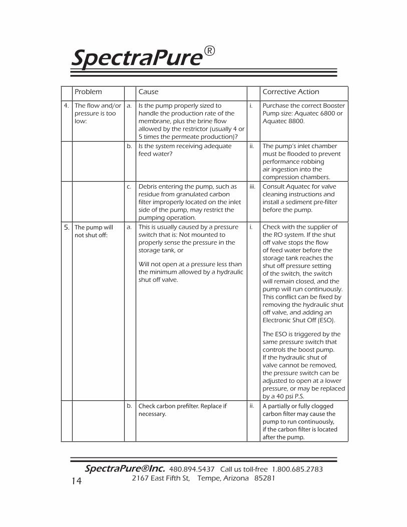
Problem Cause Corrective Action
4. The flow and/or pressure is too low:
a. Is the pump properly sized to handle the production rate of the membrane, plus the brine flow allowed by the restrictor (usually 4 or 5 times the permeate production)?
i. Purchase the correct Booster Pump size: Aquatec 6800 or Aquatec 8800.
b. Is the system receiving adequate feed water?
ii. The pump’s inlet chamber must be flooded to prevent performance robbing air ingestion into the compression chambers.
c. Debris entering the pump, such as residue from granulated carbon filter improperly located on the inlet side of the pump, may restrict the pumping operation.
iii. Consult Aquatec for valve cleaning instructions and install a sediment pre-filter before the pump.
5. The pump will not shut off :
a. This is usually caused by a pressure switch that is: Not mounted to properly sense the pressure in the storage tank, or
Will not open at a pressure less than the minimum allowed by a hydraulic shut off valve.
i. Check with the supplier of the RO system. If the shut off valve stops the flow of feed water before the storage tank reaches the shut off pressure setting of the switch, the switch will remain closed, and the pump will run continuously. This conflict can be fixed by removing the hydraulic shut off valve, and adding an Electronic Shut Off (ESO).
The ESO is triggered by the same pressure switch that controls the boost pump. If the hydraulic shut of valve cannot be removed, the pressure switch can be adjusted to open at a lower pressure, or may be replaced by a 40 psi P.S.
b. Check carbon prefi lter. Replace if necessary.
ii. A partially or fully clogged carbon fi lter may cause the pump to run continuously, if the carbon fi lter is located after the pump.

SpectraPure®Inc. Fax 480.894.6109 Fax us toll-free 1.877.527.7873E-mail: [email protected] Visit us on the web www.spectrapure.com 15
SpectraPure ®
TWO YEAR MANUFACTURERS WARRANTYEffective on products purchased after March 10, 2005.
SpectraPure, Inc.® warrants the product to the original owner only to be free of defects in material and workmanship for a period of two years from the date of receipt. SpectraPure’s liability under this warranty shall be limited to repairing or replacing at SpectraPure’s option, without charge, F.O.B. SpectraPure’s factory, any product of SpectraPure’s manufacture. SpectraPure will not be liable for any cost of removal, installation, transportation or any other charges which may arise in connection with a warranty claim. Products which are sold but not manufactured by SpectraPure are subject to the warranty provided by the manufacturer of said products and not by SpectraPure’s warranty. SpectraPure will not be liable for damage or wear to products caused by abnormal operating conditions, accident, abuse, misuse, unauthorized alteration or repair or, if the product was not installed in accordance with SpectraPure’s or other manufacture’s printed installation and operating conditions, or damage caused by hot water, freezing, flood, fire or acts of God.
SpectraPure will not be responsible for any consequential damages arising from installation or use of the product, including any water or mold damage due to flooding which may occur due to malfunction or faulty installation, including, but not limited to failure by installer to over- or under-tighten fittings, housings, and/or push-style fittings, or improper installation of push-style fittings. Consumable items such as pre filters and membranes are not covered under the two year warranty.
SpectraPure warrants (pro-rated) the performance of tested SpectraSelect™ RO membrane elements only, for one year from date of receipt by the buyer, providing that the loss of performance was not caused by fouling , neglect or water conditions exceeding the feed water parameters listed in the applicable product manual (refer to detailed membrane warranty information). SpectraPure will, on confirmation of loss of performance during the warranty period, credit the pro-rated amount of the current catalog price of the element. The disposable filters and cartridges are not covered under the warranty.
To obtain service under this warranty, the defective system or components must be returned to SpectraPure with proof of purchase, installation date, failure date and supporting installation data. Any defective product to be returned to the factory must be sent freight prepaid; documentation supporting the warranty claim and a Return Goods Authorization (RMA) number must be included. SpectraPure will not be liable for shipping damages due to the improper packaging of the returned equipment and all returned goods must also have adequate insurance coverage and a tracking number.
SpectraPure will not pay for loss or damage caused directly or indirectly by the presence, growth, proliferation, spread or any activity of “fungus”, wet or dry rot or bacteria. Such loss or damage is excluded regardless of any other cause or event that contributes concurrently or in any sequence to the loss. We will not pay for loss or damage caused by or resulting from continuous or repeated seepage or leakage of water, or the presence or condensation of humidity, moisture or vapor, that occurs over a period of 14 days or more. “Fungus” and “fungi” mean any type or form of fungus or Mycota or any by-product or type of infestation produced by such fungus or Mycota, including but not limited to, mold, mildew, mycotoxins, spores, scents or any biogenic aerosols.
SpectraPure will not be liable for any incidental or consequential damages, losses or expenses arising from installation, use, or any other causes. There are no expressed or implied warranties, including merchantability or fitness for a particular purpose, which extend beyond those warranties described or referred to above.
* The two year limited warranty does not apply to consumable items, including but not limited to, filters and cartridges unless specifically stated above
SpectraPure
SpectraPure®Inc. 480.894.5437 Call us toll-free 1.800.685.2783 2167 East Fifth St, Tempe, Arizona 85281
®
16
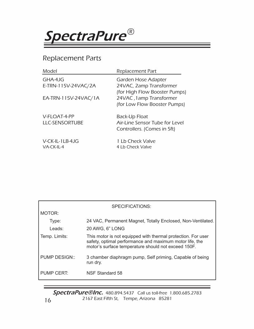
Replacement Parts
Model Replacement Part
GHA-4JG Garden Hose AdapterE-TRN-115V-24VAC/2A 24VAC, 2amp Transformer (for High Flow Booster Pumps)EA-TRN-115V-24VAC/1A 24VAC ,1amp Transformer (for Low Flow Booster Pumps)
V-FLOAT-4-PP Back-Up FloatLLC-SENSORTUBE Air-Line Sensor Tube for Level Controllers. (Comes in 5ft)
V-CK-IL-1LB-4JG 1 Lb Check ValveVA-CK-IL-4 4 Lb Check Valve
MOTOR:
Type: 24 VAC, Permanent Magnet, Totally Enclosed, Non-Ventilated.
Leads: 20 AWG, 6” LONG
Temp. Limits: This motor is not equipped with thermal protection. For user safety, optimal performance and maximum motor life, the motor’s surface temperature should not exceed 150F.
PUMP DESIGN:: 3 chamber diaphragm pump, Self priming, Capable of being run dry.
PUMP CERT: NSF Standard 58
SPECIFICATIONS: