boeing 757-200/300
TRANSCRIPT

Boeing 757-200/300


Airplane General - Dimensions

Overhead Panel

Landing Lights

Taxi Light
One taxi light is installed on the steerable portion of the nose landing gear. The light is inoperative when the nose landing gear is not down and locked.
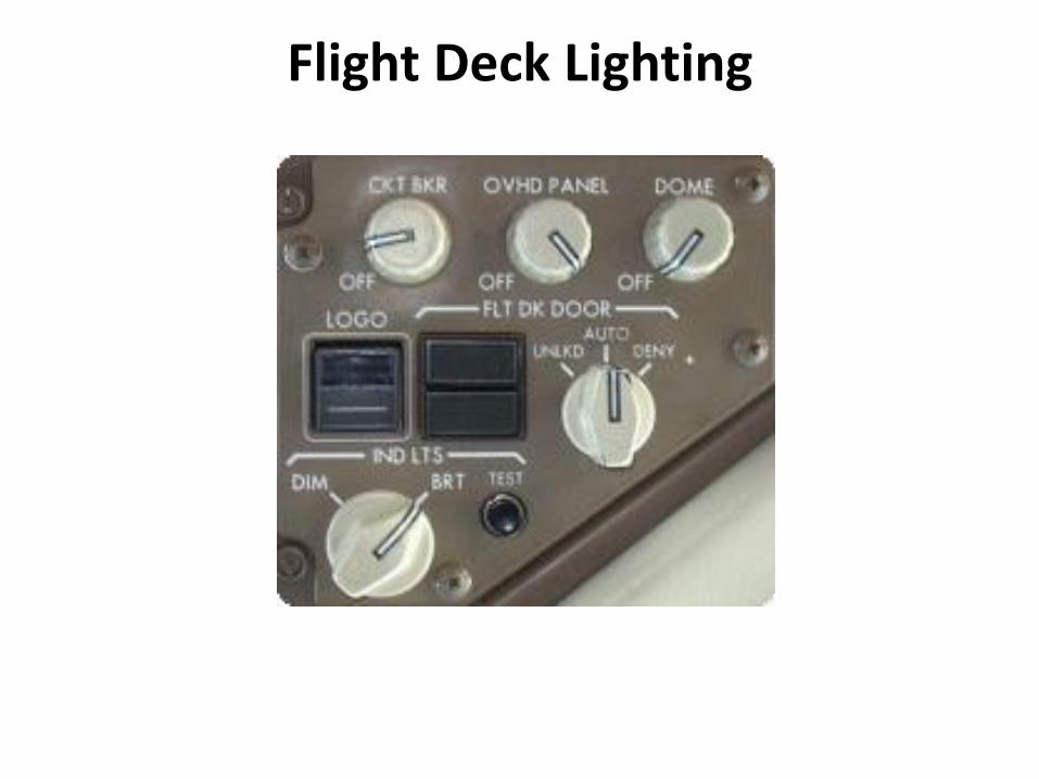
Flight Deck Lighting

Logo Lights
Logo lights are located on the stabilizer to illuminate the logo on the vertical tail surface.

Navigation (Position) Lights
The navigation lights are standard red (left forward wingtip), green (right forward wingtip) and white (aft tip of both wings) position lights.

Red Anti-Collision Lights
The red anti-collision lights are strobe lights located on the top and bottom of the fuselage.

Cargo Doors
There are two Cargo Doors; one forward and one aft. Both doors are located on the right side of the airplane. The cargo doors cannot be opened unless the Ground Handling Bus is powered by either the APU or External power

Access Doors
• Access to the forward equipment bay and the electronics bay is provided in the forward lower fuselage. If either door is not closed and locked, the ACCESS DOORS light on the overhead panel illuminates and the EICAS advisory message FWD ACCESS DOOR or E/E ACCESS DOOR displays. If both doors are open, the advisory message ACCESS DOORS appears.
Oxygen Systems

Flight Crew Oxygen System

• The Flight Crew Oxygen System uses quick-donning masks and regulators located at each crew station. Oxygen pressure is displayed on the lower EICAS status display.
• Flight Crew and observer masks and regulators are installed in Oxygen mask panels near each seat. Squeezing the red oxygen mask release levers releases the mask from the stowage. Removing the mask:
• inflates the mask harness
• momentarily displays the yellow oxygen flow indicator.
• Place the mask over the head and release the levers. The harness will contract fitting the mask to the head and face.

Oxygen Cylinder

• The crew oxygen system supplies each crew station with oxygen from a pressurized cylinder on the right side of the forward cargo compartment. There is a cylinder shutoff valve, an oxygen pressure indicator, a thermal relief port, a pressure regulator connection, and an external fill port on the neck of each cylinder. Overboard Vent
• If the crew oxygen cylinder becomes over-pressurized, a thermal relief disk on the cylinder neck breaks. The high pressure oxygen flows through an overboard vent line to the overboard vent. When pressure in the vent line reaches about 500 psi, a green disk in the overboard vent is blown out and the oxygen is vented to the air. The disk is held in place by a snap-ring. The overboard vent is just aft of the forward cargo door on the lower right side of the fuselage. The green disk is easily seen during the pre-flight check.

Oxygen Mask Panel
• Oxygen Flow Indicator • Shows a yellow cross when oxygen flowing. • RESET/TEST Switch • PUSH - With the left door closed and the Oxygen ON indicator not,
turns Oxygen ON momentarily to test regulator. • Normal/100% Switch • N - Supplies an Air/Oxygen mixture on demand (the ratio depends
on cabin altitude). • 100% - Supplies 100% Oxygen on demand. • Oxygen Mask Emergency/Test Selector • ROTATE - Supplies 100% oxygen under positive pressure at all cabin
altitudes (protects against smoke and harmful vapours). • PRESS TO TEST - Tests the positive pressure supply to the regulator.

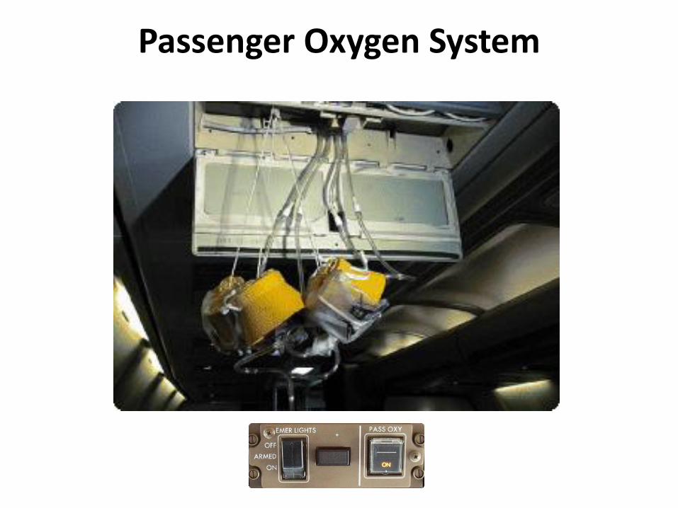
Passenger Oxygen System

Passenger Cabin Signs
The passenger cabin signs are controlled by overhead panel selectors.

FASTEN SEAT BELTS
AUTO : The FASTEN SEAT BELTS signs illuminate if: Landing Gear not up and locked, or Flap Lever not UP, or Cabin Altitude above 10,000 ft or Passenger Oxygen ON

NO SMOKING
• AUTO : The NO SMOKING signs illuminate if:
• Landing Gear not up and locked or Cabin Altitude above 10,000 ft or Passenger Oxygen ON

Note:
• All passenger signs can be controlled manually by positioning the respective selector to ON or OFF.
• Note: Anytime Passenger Oxygen is deployed, the NO SMOKING and FASTEN SEAT BELTS illuminate and RETURN TO SEAT signs extinguish, regardless of selector position.

Flight Deck Door

Remote Access Panel
After the code has been entered, an amber LED will illuminate and a buzzer will sound on the flight deck. The amber LED will extinguish and the green LED will then illuminate on the access panel, indicating door unlocked.

FLT DK DOOR SWITCH

• LOCK FAIL - illuminates when lock solenoid is not electrically powered.
• AUTO UNLK - illuminates when timer operation is activated by either deny entry or incapacitation.
• The door weighs approximately 36 Kg

Cockpit Door Surveillance System

The CDSS System consists of the following components:
• One LCD monitor in the cockpit.
• Three wide angle viewing cameras with integral light for viewing in darkness.
• System control unit.
• On-Off switch on the overhead panel.
• cabin ready switch located adjacent to Door L1.

Passenger In-flight Flight Entertainment (IFE)

VIDEO MONITORS

Passenger Entertainment System (PES)

EICAS Messages

Fire Protection SYSTEM
• There are Fire detection and extinguishing systems for the:
• Engines
• APU
• Cargo Compartments
• Lavatories

Engine Fire Protection
Engine Fire Protection consists of these systems:
• Engine Fire and Overheat Detection.
• Engine Fire Warning and Overheat Caution.
• Engine Fire Extinguishing.

Engine Fire and Overheat Detection

Engine Fire Warning
The indications of an engine fire warning are:
• The fire bell sounds .
• The master WARNING lights illuminate.
• The Engine Fire Switch LEFT or RIGHT fire warning light illuminates.
• The discrete FIRE warning light illuminates.
• The engine FUEL CONTROL switch fire warning light illuminates.
• The EICAS warning message L/R ENGINE FIRE displays.
• The engine fire switch unlocks.

The fire warning lights remain illuminated as long as the fire signal exists. The fire bell may be silenced by any of the following actions:
• Extinguishing the fire.
• Pushing either Master WARNING/CAUTION Reset Switch.
• Pulling the appropriate fire switch.
• The fire warning bell rings intermittently for 2 seconds on, then 3 seconds off.

Engine Fire Extinguishing

When the fire switch is pulled out • The Engine Fuel valves are shutoff • The Engine Bleed Valves are closed • The Generator is tripped off • The Hydraulic fluid is shutoff • The fire extinguisher is armed • The fire alarm bell is silenced • The Thrust Reverser is deactivated

• Rotating the fire switch in either direction discharges a single extinguisher bottle into the associated engine. Rotating the engine fire switch in the other direction discharges the remaining extinguisher bottle into the same engine.

Lavatory Fire Protection
• Lavatory fire protection consists of these systems:
• lavatory fire detection.
• lavatory waste container fire extinguishing.

Lavatory Fire Detection
Each lavatory has a single smoke detector. If smoke is detected: An aural alert (chime) sounds in the lavatory and in the cabin the lavatory call light flashes The master call light at the associated flight attendant station illuminates The LAV SMOKE Light illuminates and the EICAS advisory message LAVATORY SMOKE displays when smoke is detected in any lavatory.

Lavatory Fire Extinguishing
• Each lavatory has a fire extinguisher located in the waste container cabinet. Fire extinguisher operation is automatic. There is no flight deck indication.

Warning Systems

The Warning System consists of
• two flight deck warning speakers,
• two master WARNING lights
• two stick shaker motors, controlled by a Warnings Electronics Unit.

• Fire • Cabin Altitude • Autopilot disconnect • Ground Proximity • Over speed • Unscheduled Stabilizer movement • As Installed - Wind shear • As Installed - Traffic Alert and Collision Avoidance
System • The warning system also provides: • Takeoff Configuration warnings • Landing Configuration warnings • Stall warning


Takeoff Configuration Warnings
Takeoff configuration warnings are armed when the airplane is on the ground and thrust is in the takeoff range (greater than 66.7% N1) on either engine.

Landing Configuration Warning
• The landing configuration warning system alerts the crew that the Landing Gear is not extended for landing

Stall Warning
Warning of an impending stall is provided by two independent stall warning systems controlling left and right stick shakers, which independently vibrate the left and right control columns

GROUND PROXIMITY WARNING SYSTEM

Radio Altitude Based Alerts
• Excessive descent rate
• Excessive terrain closure rate
• Altitude loss after takeoff or go-around
• Unsafe terrain clearance when not in the landing configuration
• Excessive deviation below an ILS glide slope
• Altitude Callouts
• Wind shear Detection
