body builder instructions - volvo trucks builder instructions volvo trucks north america engine,...
TRANSCRIPT
Body Builder InstructionsVolvo Trucks North America
Engine, General InformationVN, VHD, VAH
Section 2
General Information
This information provides details concerning engines available for Volvo vehicles.
Note:We have attempted to cover as much information as possible. However, thisinformation does not cover all the unique variations that a vehicle may present. Note thatillustrations are typical but may not reflect all the variations of assembly.
All data provided is based on information that was current at time of release. However,this information is subject to change without notice.
Please note that no part of this information may be reproduced, stored, or transmitted byany means without the express written permission of Volvo Trucks North America.
Contents:• “Introduction”, page 3
• “Engine Operation”, page 4
• “Engine Overview, D11 and D13”, page 6
• “Engine Overview, D16 ”, page 8
• “Exhaust Emissions and Aftertreatment Diesel Particulate Filters (DPFs)”, page 10
• “DPF Systems and Temperatures”, page 14
• “Diesel Exhaust Fluid (DEF)”, page 18
• “Aftertreatment Control Module (ACM)”, page 19
• “Exhaust Diffusers ”, page 20
• “Heated Dump Bodies With VOLVO Engines”, page 21
• “In-Transit Heat Cooling System ”, page 23
• “Smart NOx Sensor”, page 26
• “Engine Overspeed”, page 27
Volvo Body Builder Instructions VN, VHD, VAH, Section 2
USA139046946 Date 5.2017 Page 1 (36)
All Rights Reserved
• “Engine Idling”, page 28
• “Enhanced Cruise with the VOLVO Enhanced Stability System”, page 30
• “Fittings, Fuel Line, Replacement”, page 34
VN, VHD, VAH, Section 2
USA139046946 Date 5.2017 Release Page 2 (36)
Overview of the VOLVO Engines
IntroductionIn 2010, the VOLVO engine family consists of three engines: D11, D13 and D16. The VOLVO engines meet the very stringentnew emissions standards which apply to all heavy-duty diesel engines built after January 1, 2010 for on-highway trucks. Thenew standards for US 2010 requires 83% reduction in nitrogen oxides (NOx). This represents a total reduction of 99% of allemissions from original levels.
Key Features of the VOLVO engines:
• Improved Fuel Economy
• Extended Oil Drain Intervals
• Improved Cooling Capacity
• Low Maintenance Catalyzed Aftertreatment Diesel Particulate Filter (DPF)
• Enhanced Engine Brake Performance
• Selective Catalytic Reduction (SCR)
Fuel
CAUTION
Diesel engines for US 2010 vehicles are designed to operate only with ultra low sulfur diesel (ULSD) fuel. Use of fuel otherthan ULSD will reduce the efficiency and durability of the engine, permanently damage the advanced emission control sys-tems, reduce fuel economy and possibly prevent the engine from running at all. Manufacturer's warranties are likely to berendered void by usage of improper or incorrect fuel, and usage of fuels other than ULSD fuel in diesel-powered vehiclesis illegal and punishable with civil penalties. Use of fuel additives to compensate for the lower sulfur content is NOT recom-mended by Volvo Trucks North America.
Fuel sold for use in diesel-powered engines for US 2010 vehicles may only contain a maximum sulfur content of 0.0015% byweight. This was done to reduce particle emissions in the exhaust.
Bio DieselThe only Bio Diesel Fuel approved by Volvo Truck North America for use in US 2010 VOLVO engines is soy methyl ester(SME or SOME) in blends up to B20 Concentration (20% blend).
Note: Although higher concentrations are available, concentration up to B20 (maximum) are the only blends currently ap-proved by Volvo Trucks North America.
Greenhouse Gas 2017Maximum limit will be B10 concentration (10% blend).
Engine OilNote: For Cummins engine oil specifications, refer to the Cummins owner's manual.
EO-O Premium Plus (or VDS-4) diesel engine oil is mandatory for use in all US 2010 emission compliant VOLVO engines.Chassis equipped with a US 2010 emission compliant engine, which can be identified by the presence of an AftertreatmentSelective Catalytic Reduction (SCR) system, also require the use of ultra low sulfur diesel (ULSD) fuel. EO-O Premium Plusoils exceed the new American Petroleum Institute (API) service category CJ-4.
Volvo Body Builder Instructions VN, VHD, VAH, Section 2
USA139046946 Date 5.2017 Engine, General Information Page 3 (36)
All Rights Reserved
Engine Operation
DANGER
Do not use ether or other combustible starting aids in any VOLVO engine. Introduction of ether or similar starting aidscould cause a fire or explosion resulting in severe property damage, serious personal injury or death.
CAUTION
DO NOTcrank the engine for more than 30 seconds at a time; wait two minutes after each try to allow the starter to cool.Failure to follow these instructions could cause starter damage.
Note: Some starters are equipped with starter protection. If the engine is running, the starter temperature is too high, thetransmission is not in neutral or the clutch pedal is not pressed, starter engagement is inhibited.
Allow the engine to slow down and idle for three to five minutes before shutting it off. This allows the turbocharger to cooldown and the cooling system to dissipate the engine heat. Switch the engine off by turning the ignition key to the OFFposition.
CAUTION
Shutting off an engine immediately after high speed or full load operation can damage the turbocharger and cause heatstress in the engine. Always let the engine idle for three to five minutes before shutting it off.
Volvo Trucks North America does not recommend the use of winterfronts, shutters or any other shield in front of the grille orradiator package under normal circumstances. Today's electronically controlled engines are designed to operate in cold tem-peratures without a winterfront. These devices, if not used properly, can cause higher exhaust gas temperatures, power loss,excessive fan usage, failure of the charge air cooler (CAC) and a reduction in fuel economy. Winterfronts can be used in thewintertime during very cold weather if used properly. In these cases, engine coolant and intake air temperatures must alsobe carefully monitored and controlled.
CAUTION
VOLVO is now using the ambient air temperature (AAT) sensor for on board diagnostic (OBD) monitoring. If a customer in-stalls a winterfront or blocks the radiator opening and blocks airflow to the sensor, they will likely set an OBD diagnostictrouble code (DTC) for inaccurate sensor data due to restricted airflow across the sensor.
Volvo Body Builder Instructions VN, VHD, VAH, Section 2
USA139046946 Date 5.2017 Engine, General Information Page 4 (36)
All Rights Reserved
Engine Shutdown System
DANGER
Failure to take the necessary precautions when the STOP telltale is ON can result in automatic engine shutdown and theloss of power steering. Vehicle crash can occur.
The engine shutdown system will automatically derate or stop the engine when one or more of the conditions listed belowreaches a critical stage:
• High Engine Coolant Temperature (ECT)
• Low Engine Oil Pressure (EOP)
• Low Engine Coolant Level (ECL)
• High Crankcase Pressure (CCP)
When the shutdown is activated, the telltales come on along with display symbols and the buzzer is also activated. After abrief time, the engine shuts down. Find a safe place to pull off the road as soon as possible.
After the engine has been shut down by the system, turn the ignition key to the OFF position. If necessary, the engine can berestarted for a brief time so that the vehicle may be pulled off the road.
The alarm will remain activated until repairs have been made to correct the problem that caused the shutdown.
CAUTION
Continuously restarting the engine once the shutdown system is active may result in severe engine damage.
Refer to the Driver Information Display manual for information about the display symbols.
W3005171
Notes
Volvo Body Builder Instructions VN, VHD, VAH, Section 2
USA139046946 Date 5.2017 Engine, General Information Page 5 (36)
All Rights Reserved
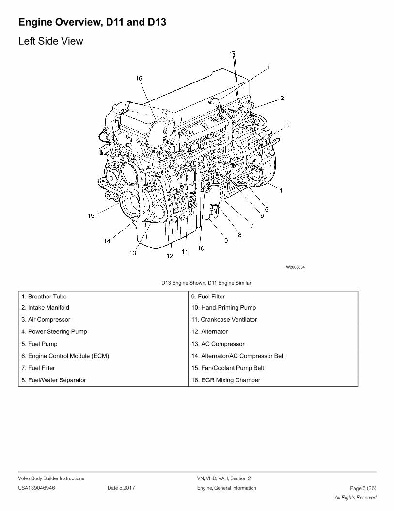
Engine Overview, D11 and D13
Left Side View
W2006034
D13 Engine Shown, D11 Engine Similar
1. Breather Tube 9. Fuel Filter
2. Intake Manifold 10. Hand-Priming Pump
3. Air Compressor 11. Crankcase Ventilator
4. Power Steering Pump 12. Alternator
5. Fuel Pump 13. AC Compressor
6. Engine Control Module (ECM) 14. Alternator/AC Compressor Belt
7. Fuel Filter 15. Fan/Coolant Pump Belt
8. Fuel/Water Separator 16. EGR Mixing Chamber
Volvo Body Builder Instructions VN, VHD, VAH, Section 2
USA139046946 Date 5.2017 Engine, General Information Page 6 (36)
All Rights Reserved
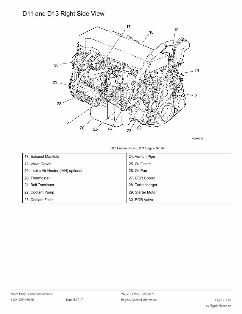
D11 and D13 Right Side View
W2006035
D13 Engine Shown, D11 Engine Similar
17. Exhaust Manifold 24. Venturi Pipe
18. Valve Cover 25. Oil Filters
19. Intake Air Heater (IAH) optional 26. Oil Pan
20. Thermostat 27. EGR Cooler
21. Belt Tensioner 28. Turbocharger
22. Coolant Pump 29. Starter Motor
23. Coolant Filter 30. EGR Valve
Volvo Body Builder Instructions VN, VHD, VAH, Section 2
USA139046946 Date 5.2017 Engine, General Information Page 7 (36)
All Rights Reserved
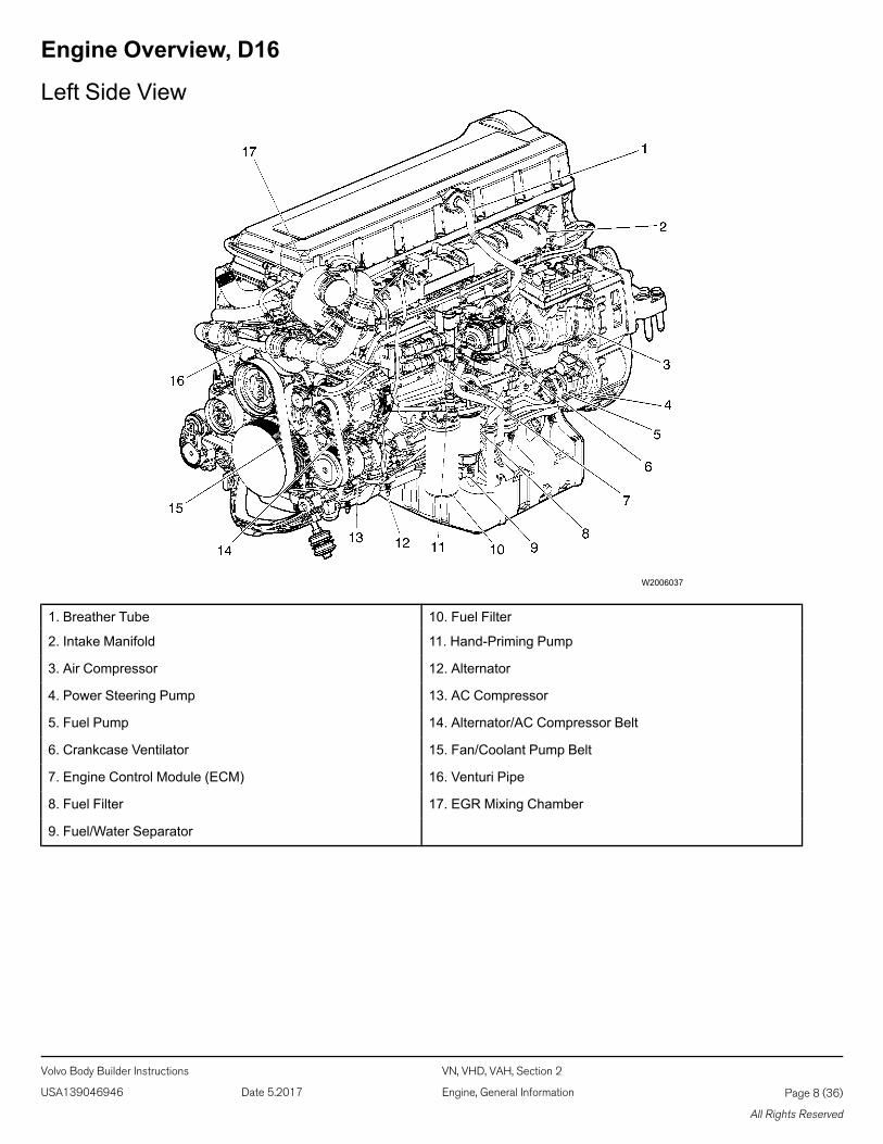
Engine Overview, D16
Left Side View
W2006037
1. Breather Tube 10. Fuel Filter
2. Intake Manifold 11. Hand-Priming Pump
3. Air Compressor 12. Alternator
4. Power Steering Pump 13. AC Compressor
5. Fuel Pump 14. Alternator/AC Compressor Belt
6. Crankcase Ventilator 15. Fan/Coolant Pump Belt
7. Engine Control Module (ECM) 16. Venturi Pipe
8. Fuel Filter 17. EGR Mixing Chamber
9. Fuel/Water Separator
Volvo Body Builder Instructions VN, VHD, VAH, Section 2
USA139046946 Date 5.2017 Engine, General Information Page 8 (36)
All Rights Reserved
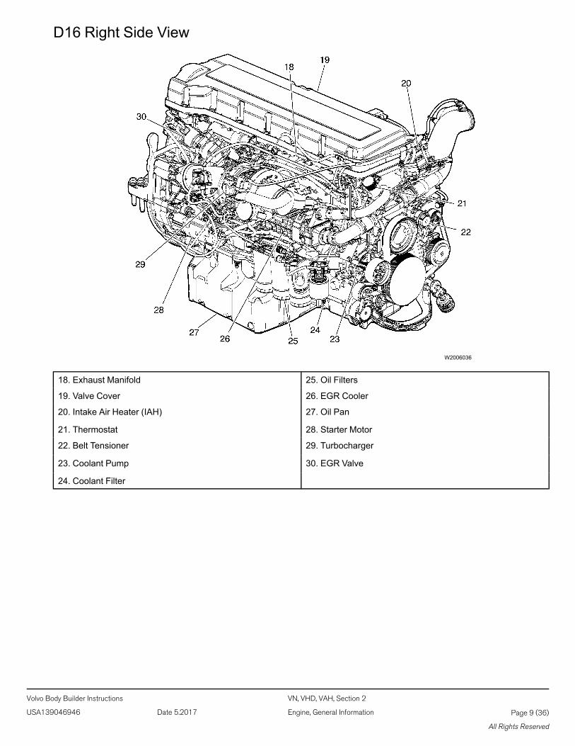
D16 Right Side View
W2006036
18. Exhaust Manifold 25. Oil Filters
19. Valve Cover 26. EGR Cooler
20. Intake Air Heater (IAH) 27. Oil Pan
21. Thermostat 28. Starter Motor
22. Belt Tensioner 29. Turbocharger
23. Coolant Pump 30. EGR Valve
24. Coolant Filter
Volvo Body Builder Instructions VN, VHD, VAH, Section 2
USA139046946 Date 5.2017 Engine, General Information Page 9 (36)
All Rights Reserved
Exhaust Emissions and Aftertreatment Diesel Particulate Filters(DPFs)General
USA
Emissions Control Compliance: The Federal Clean Air Act, Section 203 (a) (3), states the following concerning the removalof air pollution control devices or modification of a certified engine to a non-certified configuration:
“The following acts and the causing thereof are prohibited:
(3) For any person to remove or render inoperative any device or element of design installed on or in a motor vehicle or motorvehicle engine in compliance with regulations under this part prior to its sale and delivery to the ultimate purchaser, or for anymanufacturer or dealer knowingly to remove or render inoperative any such design after sale and delivery to the ultimatepurchaser.”
Specifically, please note that no person may make such changes prior to the sale and delivery of the vehicle to the ultimatepurchaser, and, in addition, no manufacturer or dealer may make take such action after sale and delivery of the vehicle to theultimate purchaser. The law provides a penalty of up to $10,000 for each violation.
Modifications, such as reprogramming of the fuel system so the engine will exceed the certified horsepower or torque, or re-moving the mufflers are examples of illegal changes.
Changes should not be made to a certified engine that would result in an engine that does not match the configuration of anengine model that is currently certified to meet Federal Standards.
MexicoThe same conditions that apply in the USA apply to Mexico. Refer to the Mexican Federal Law for Emission Control whichadheres to EPA regulations. No changes should be made that render any or all of the emissions control devices inoperative.If the owner/operator wishes to make changes to the emission control devices, check with the state authority before changesare made.
Canada
The same conditions that apply in the USA apply to Canada, with one exception. After the vehicle is sold to a retail customer,that is, the end user, the jurisdiction controlling the emission control devices becomes the province in which the vehicle is li-censed. No changes should be made that render any or all of the devices inoperative.
Should the owner/operator wish to make any changes to the emission control devices, check with the provincial authority be-fore making any such changes.
Notes
Volvo Body Builder Instructions VN, VHD, VAH, Section 2
USA139046946 Date 5.2017 Engine, General Information Page 10 (36)
All Rights Reserved
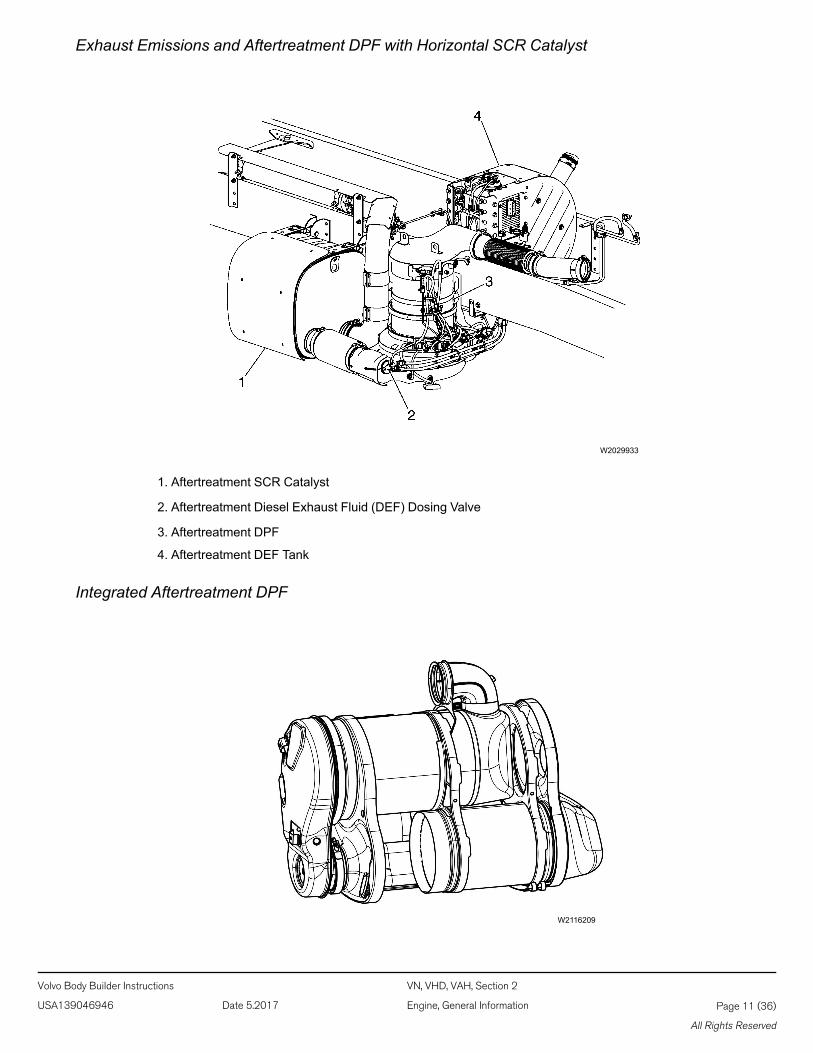
Exhaust Emissions and Aftertreatment DPF with Horizontal SCR Catalyst
W2029933
1. Aftertreatment SCR Catalyst
2. Aftertreatment Diesel Exhaust Fluid (DEF) Dosing Valve
3. Aftertreatment DPF
4. Aftertreatment DEF Tank
Integrated Aftertreatment DPF
W2116209
Volvo Body Builder Instructions VN, VHD, VAH, Section 2
USA139046946 Date 5.2017 Engine, General Information Page 11 (36)
All Rights Reserved
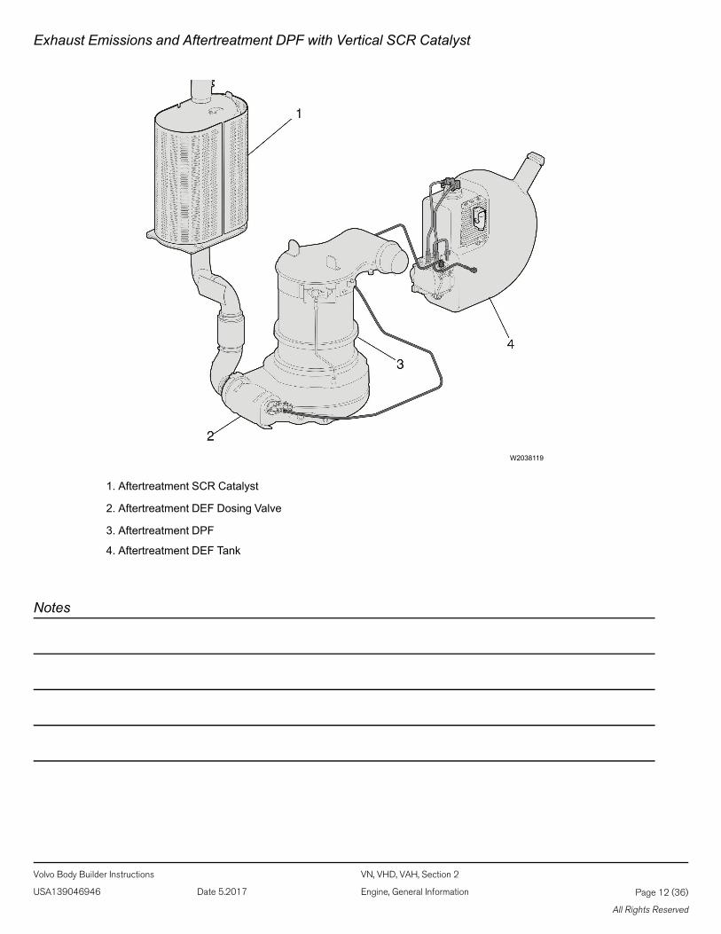
Exhaust Emissions and Aftertreatment DPF with Vertical SCR Catalyst
W2038119
1. Aftertreatment SCR Catalyst
2. Aftertreatment DEF Dosing Valve
3. Aftertreatment DPF
4. Aftertreatment DEF Tank
Notes
Volvo Body Builder Instructions VN, VHD, VAH, Section 2
USA139046946 Date 5.2017 Engine, General Information Page 12 (36)
All Rights Reserved
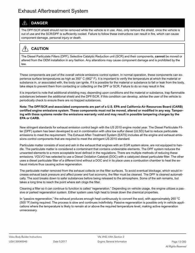
Exhaust Aftertreatment System
DANGER
The DPF/SCR shield should not be removed while the vehicle is in use. Also, only remove the shield, once the vehicle isout of use and the SCR/DPF is sufficiently cooled. Failure to follow these instructions can result in fire, which can causecomponent damage, personal injury or death.
CAUTION
The Diesel Particulate Filters (DPF), Selective Catalytic Reduction unit (SCR) and their components, cannot be moved oraltered from the OEM installation in any fashion. Any alterations may cause component damage and is prohibited by thelaw.
These components are part of the overall vehicle emissions control system. In normal operation, these components can ex-perience surface temperatures as high as 350° C (662° F). It is important to verify the temperature at which the material orsubstance in, or associated with, the body can ignite. If it is possible for the material or substance to fall or leak from the body,take steps to prevent them from contacting or collecting on the DPF or SCR. Failure to do so may result in fire.
It is important to note that additional shielding may, depending upon conditions and the material or substance, trap flammablesubstances between the additional shield and the DPF/SCR. If this condition can develop, advise the user of the vehicle toperiodically check to ensure there are no trapped substances.
Note: The DPF/SCR and associated components are part of a U.S. EPA and California Air Resources Board (CARB)certified engine emissions system. These components must not be moved, altered or modified in any way. Tamper-ing with these systems render the emissions warranty void and may result in possible tampering charges by theEPA or CARB.
New stringent standards for exhaust emission control begin with the US 2010 engine model year. The Diesel Particulate Fil-ter (DPF) system has been developed to act in combination with ultra low sulfur diesel (ULSD) fuel to reduce particulateemissions to meet the requirement. The Exhaust After-Treatment System (EATS) includes all the engine and exhaust emis-sions control components that are required to meet the stringent US 2010 standard.
Particulate matter consists of soot and ash in the exhaust that engines with an EGR system alone, are not equipped to han-dle. The particulate matter is considered a contaminant that contains undesirable elements. The DPF system reduces theunwanted elements to a more acceptable level defined in the regulations. There are multiple methods of reducing theseemissions. VOLVO has selected to use a Diesel Oxidation Catalyst (DOC) with a catalyzed diesel particulate filter. The otheruses a diesel particulate filter of a different kind without a DOC and in its place uses a combustion chamber to heat the ex-haust mixture thus causing active regeneration.
The particulate matter removed from the exhaust collects on the filter surfaces. To avoid eventual blockage, which would in-crease exhaust back pressure and affect power and fuel economy, the filter must be cleaned. The DPF is cleaned automati-cally. The soot breaks down to safer substances before being released to the atmosphere. Some of the ash remains, buttakes a long time to reach the point where ash clogs the filter.
Cleaning a filter so it can continue to function is called “regeneration.” Depending on vehicle usage, the engine utilizes a pas-sive or parked regeneration system. Either system uses high heat to break down the chemical properties.
In “passive regeneration,” the exhaust produces enough heat continuously to convert the soot, with approximately 260 °C(500 °F) being required. The process is slow and continues indefinitely. Passive regeneration is possible only in vehicle appli-cations where the temperature is likely to remain at or above the required temperature level, making active regenerationunnecessary.
Volvo Body Builder Instructions VN, VHD, VAH, Section 2
USA139046946 Date 5.2017 Engine, General Information Page 13 (36)
All Rights Reserved
Parked regeneration is initiated manually by the driver when alerted by the dash. The vehicle must be stationary to begin theregeneration, and remain stationary to complete.
The Aftertreatment DPF Regeneration system is self-monitoring. Under certain duty cycles driver action is needed to performa parked regeneration. When driver action is needed to perform a parked regeneration the Aftertreatment DPF RegenerationNeeded icon on the instrument cluster flashes and the message “Parked REGEN Needed” is displayed. Initiate a parkedAftertreatment DPF regeneration at the next stop.
WARNING
Prior to ever working on the exhaust, allow time for the entire exhaust system to cool. Failure to do so may result in person-al injury. Severe burns can occur.
DPF Systems and Temperatures
The VOLVO systems chemically alters soot by high heat into a harmless gas which passes out through the stack pipe. Atthese high temperatures, the process is relatively rapid (10–12 minutes). Eventually, the filter must be removed to permitclearing away of the ash with special equipment.
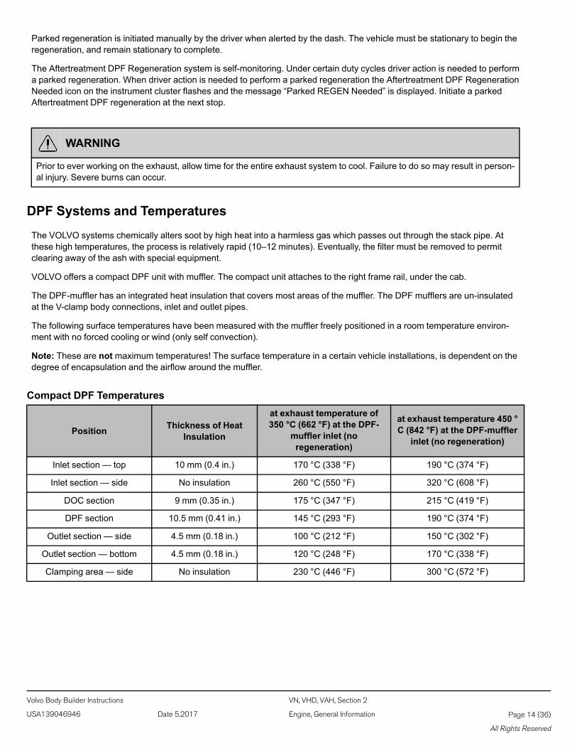
VOLVO offers a compact DPF unit with muffler. The compact unit attaches to the right frame rail, under the cab.
The DPF-muffler has an integrated heat insulation that covers most areas of the muffler. The DPF mufflers are un-insulatedat the V-clamp body connections, inlet and outlet pipes.
The following surface temperatures have been measured with the muffler freely positioned in a room temperature environ-ment with no forced cooling or wind (only self convection).
Note: These are notmaximum temperatures! The surface temperature in a certain vehicle installations, is dependent on thedegree of encapsulation and the airflow around the muffler.
Compact DPF Temperatures
Position Thickness of HeatInsulation
at exhaust temperature of350 °C (662 °F) at the DPF-
muffler inlet (noregeneration)
at exhaust temperature 450 °C (842 °F) at the DPF-muffler
inlet (no regeneration)
Inlet section — top 10 mm (0.4 in.) 170 °C (338 °F) 190 °C (374 °F)
Inlet section — side No insulation 260 °C (550 °F) 320 °C (608 °F)
DOC section 9 mm (0.35 in.) 175 °C (347 °F) 215 °C (419 °F)
DPF section 10.5 mm (0.41 in.) 145 °C (293 °F) 190 °C (374 °F)
Outlet section — side 4.5 mm (0.18 in.) 100 °C (212 °F) 150 °C (302 °F)
Outlet section — bottom 4.5 mm (0.18 in.) 120 °C (248 °F) 170 °C (338 °F)
Clamping area — side No insulation 230 °C (446 °F) 300 °C (572 °F)
Volvo Body Builder Instructions VN, VHD, VAH, Section 2
USA139046946 Date 5.2017 Engine, General Information Page 14 (36)
All Rights Reserved
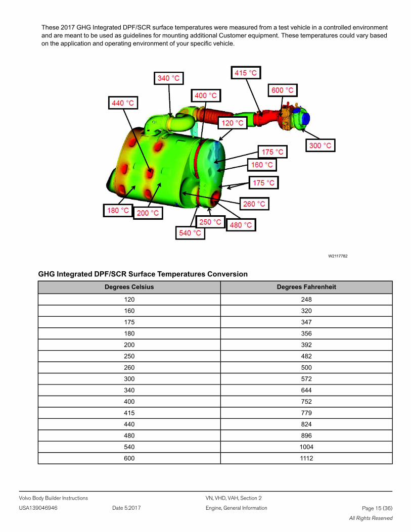
These 2017 GHG Integrated DPF/SCR surface temperatures were measured from a test vehicle in a controlled environmentand are meant to be used as guidelines for mounting additional Customer equipment. These temperatures could vary basedon the application and operating environment of your specific vehicle.
W2117782
GHG Integrated DPF/SCR Surface Temperatures ConversionDegrees Celsius Degrees Fahrenheit
120 248
160 320
175 347
180 356
200 392
250 482
260 500
300 572
340 644
400 752
415 779
440 824
480 896
540 1004
600 1112
Volvo Body Builder Instructions VN, VHD, VAH, Section 2
USA139046946 Date 5.2017 Engine, General Information Page 15 (36)
All Rights Reserved
Selective Catalytic Reduction (SCR)
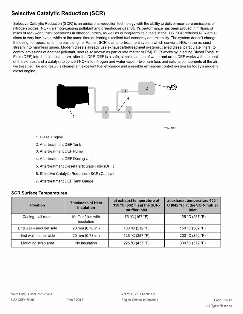
Selective Catalytic Reduction (SCR) is an emissions-reduction technology with the ability to deliver near-zero emissions ofnitrogen oxides (NOx), a smog-causing pollutant and greenhouse gas. SCR's performance has been proved in millions ofmiles of real-world truck operations in other countries, as well as in long-term field tests in the U.S. SCR reduces NOx emis-sions to very low levels, while at the same time delivering excellent fuel economy and reliability. The system doesn't changethe design or operation of the basic engine. Rather, SCR is an aftertreatment system which converts NOx in the exhauststream into harmless gases. Modern diesels already use exhaust aftertreatment systems, called diesel particulate filters, tocontrol emissions of another pollutant, soot (also known as particulate matter or PM). SCR works by injecting Diesel ExhaustFluid (DEF) into the exhaust steam, after the DPF. DEF is a safe, simple solution of water and urea. DEF works with the heatof the exhaust and a catalyst to convert NOx into nitrogen and water vapor - two harmless and natural components of the airwe breathe. The end result is cleaner air, excellent fuel efficiency and a reliable emissions control system for today's moderndiesel engine.
W2031651
1. Diesel Engine
2. Aftertreatment DEF Tank
3. Aftertreatment DEF Pump
4. Aftertreatment DEF Dosing Unit
5. Aftertreatment Diesel Particulate Filter (DPF)
6. Selective Catalytic Reduction (SCR) Catalyst
7. Aftertreatment DEF Tank Gauge
SCR Surface Temperatures
Position Thickness of HeatInsulation
at exhaust temperature of350 °C (662 °F) at the SCR-
muffler inlet
at exhaust temperature 450 °C (842 °F) at the SCR-muffler
inlet
Casing – all round Muffler filled withinsulation
75 °C (167 °F) 125 °C (257 °F)
End wall – in/outlet side 20 mm (0.78 in.) 100 °C (212 °F) 150 °C (302 °F)
End wall – other side 20 mm (0.78 in.) 125 °C (257 °F) 200 °C (392 °F)
Mounting strap area No insulation 225 °C (437 °F) 300 °C (572 °F)
Volvo Body Builder Instructions VN, VHD, VAH, Section 2
USA139046946 Date 5.2017 Engine, General Information Page 16 (36)
All Rights Reserved
CAUTION
Do not put diesel fuel in the Aftertreatment DEF tank. Diesel fuel, if sprayed into the hot exhaust along with the DEF, couldignite explosively causing a fire resulting in personal injury or damage to the exhaust system.
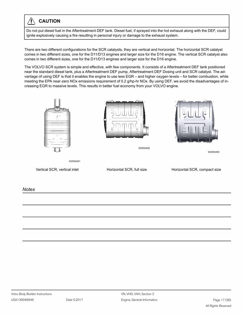
There are two different configurations for the SCR catalysts, they are vertical and horizontal. The horizontal SCR catalystcomes in two different sizes, one for the D11/D13 engines and larger size for the D16 engine. The vertical SCR catalyst alsocomes in two different sizes, one for the D11/D13 engines and larger size for the D16 engine.
The VOLVO SCR system is simple and effective, with few components. It consists of a Aftertreatment DEF tank positionednear the standard diesel tank, plus a Aftertreatment DEF pump, Aftertreatment DEF Dosing unit and SCR catalyst. The ad-vantage of using DEF is that it enables the engine to use less EGR – and higher oxygen levels – for better combustion, whilemeeting the EPA near-zero NOx emissions requirement of 0.2 g/hp-hr NOx. By using DEF, we avoid the disadvantages of in-creasing EGR to massive levels. This results in better fuel economy from your VOLVO engine.
W2055491
W2055492W2055493
Vertical SCR, vertical inlet Horizontal SCR, full size Horizontal SCR, compact size
Notes
Volvo Body Builder Instructions VN, VHD, VAH, Section 2
USA139046946 Date 5.2017 Engine, General Information Page 17 (36)
All Rights Reserved
W3036787
Diesel Exhaust Fluid (DEF)
Diesel Exhaust Fluid (DEF) is a reactant that's key to the SCR process. It's a nontoxic, aqueous solution of 32.5% urea and67.5% water. Urea is a compound of nitrogen that turns to ammonia when heated. It is used in a variety of industries, per-haps most commonly as a fertilizer in agriculture. The fluid is not flammable, nor is it dangerous when handled normally.However, it is corrosive to metal, particularly copper and aluminium. Read the separate section concerning the handling ofDEF solution.
Diesel Exhaust Fluid (DEF) Handling
When handling DEF solution, it is important that electrical connectors to be connected or well encapsulated. Otherwise thereis a risk that the DEF will cause oxidation that cannot be removed. Water or compressed air does not help, since DEF quicklyoxidizes metal. If a connector comes into contact with the DEF solution it must be replaced immediately to prevent the DEFsolution from creeping further into the copper wiring, which takes place at a speed of about 60 cm (2.4 in) per hour.
CAUTION
When detaching hoses and components, do not spill DEF on disconnected connectors. If DEF is spilled on a connector,the connector must be replaced immediately.
Things to know about spilled Diesel Exhaust Fluid (DEF)
If urea solution comes into contact with the skin, rinse with plenty of water and remove contaminated clothing.
If urea solution comes into contact with the eyes rinse for several minutes and call for medical help if necessary.
If inhaled breathe fresh air and call for medical help if necessary.
Do not allow the DEF solution to come into contact with other chemicals.
The DEF solution is not flammable. If the DEF solution is exposed to high temperatures for long periods of time, it breaksdown into ammonia and carbon dioxide.
The DEF solution is corrosive to certain metals, including copper and aluminium. This is similar to the corrosion caused bysalt water.
If the DEF solution is spilled onto the vehicle, wipe off the excess and rinse with water. Spilled DEF solution can form concen-trated white crystals on the vehicle. Rinse off these crystals with water.
Volvo Body Builder Instructions VN, VHD, VAH, Section 2
USA139046946 Date 5.2017 Engine, General Information Page 18 (36)
All Rights Reserved
Note: Do not flush DEF spills into the normal drain system.
WARNING
DEF split onto hot components will quickly vaporize. Turn your face away!
Diesel Exhaust Fluid (DEF) Consumption
DEF consumption is related to fuel consumption. A highway truck may travel 225-300 miles or more on one gallon of DEF. Agauge much like a fuel gauge will indicate the level of DEF in the tank. A DEF low-level warning activates when DEF is low. Ifa driver runs out of DEF completely, vehicle power will be reduced to derate mode. When the DEF tank is refilled, the enginewill resume normal power.
Note: DEF tanks are sized for a two to one fuel to DEF ratio in order to meet US 2010 requirements.
Diesel Exhaust Fluid (DEF) Availability
DEF is available in 2.5 gallon containers, 55 gallon drums, 275 gallon IBC and in bulk storage for fleet locations, truck stopsand dealerships. All major truck stops, dealers and distributors carry DEF. For more information on DEF and availabilityplease visit the website www.Volvoscr.com.
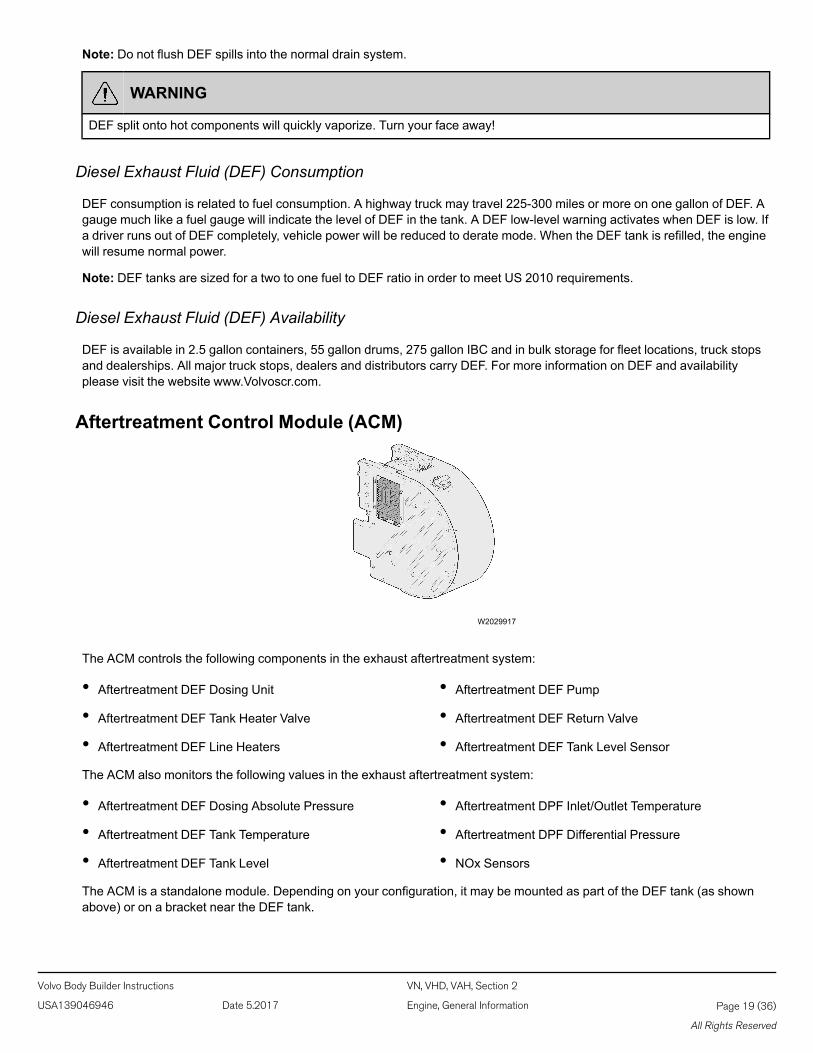
Aftertreatment Control Module (ACM)
W2029917
The ACM controls the following components in the exhaust aftertreatment system:
• Aftertreatment DEF Dosing Unit
• Aftertreatment DEF Tank Heater Valve
• Aftertreatment DEF Line Heaters
• Aftertreatment DEF Pump
• Aftertreatment DEF Return Valve
• Aftertreatment DEF Tank Level Sensor
The ACM also monitors the following values in the exhaust aftertreatment system:
• Aftertreatment DEF Dosing Absolute Pressure
• Aftertreatment DEF Tank Temperature
• Aftertreatment DEF Tank Level
• Aftertreatment DPF Inlet/Outlet Temperature
• Aftertreatment DPF Differential Pressure
• NOx Sensors
The ACM is a standalone module. Depending on your configuration, it may be mounted as part of the DEF tank (as shownabove) or on a bracket near the DEF tank.
Volvo Body Builder Instructions VN, VHD, VAH, Section 2
USA139046946 Date 5.2017 Engine, General Information Page 19 (36)
All Rights Reserved
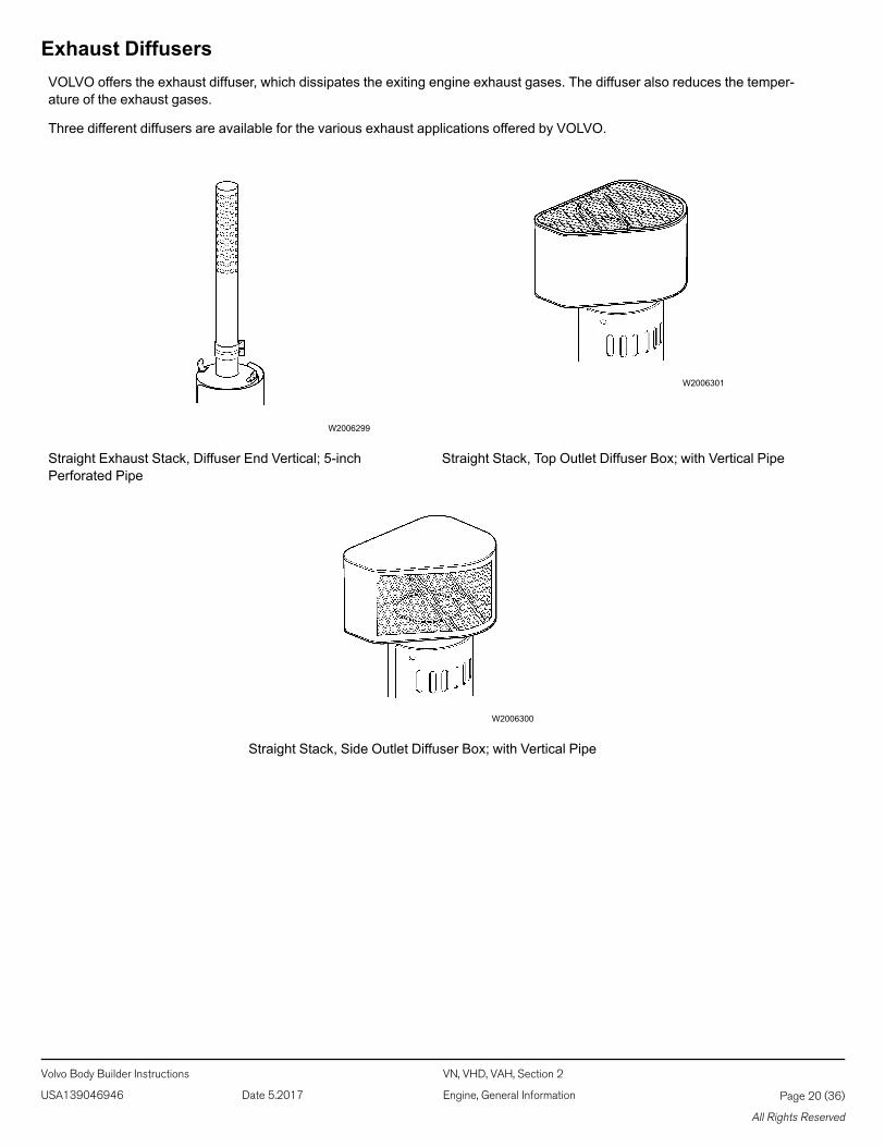
Exhaust DiffusersVOLVO offers the exhaust diffuser, which dissipates the exiting engine exhaust gases. The diffuser also reduces the temper-ature of the exhaust gases.
Three different diffusers are available for the various exhaust applications offered by VOLVO.
W2006299
W2006301
Straight Exhaust Stack, Diffuser End Vertical; 5-inchPerforated Pipe
Straight Stack, Top Outlet Diffuser Box; with Vertical Pipe
W2006300
Straight Stack, Side Outlet Diffuser Box; with Vertical Pipe
Volvo Body Builder Instructions VN, VHD, VAH, Section 2
USA139046946 Date 5.2017 Engine, General Information Page 20 (36)
All Rights Reserved
Heated Dump Bodies With VOLVO Engines
CAUTION
Due to the higher exhaust temperatures created during the regeneration process of Diesel Particulate Filter equipped ve-hicles, it is strongly recommended to consult your heated dump body supplier to verify that these temperatures will not ad-versely affect their product. Failure to do so may result in component damage.
The exhaust aftertreatment system virtually eliminates exhaust smoke. Exhaust vapor (water condensation) may be visibleduring a cold start. If exhaust smoke is visible during engine operation, this indicates a problem with the exhaust aftertreat-ment system. Take the vehicle to an authorized VOLVO Truck dealer immediately.
Vehicles equipped with a US 2010 emission compliant engine have an exhaust aftertreatment system which includes a Se-lective Catalytic Reduction (SCR) system and a Catalyzed Aftertreatment Diesel Particulate Filter (DPF). The AftertreatmentDPF takes the place of the standard muffler, and it reduces soot and particulate emissions into the atmosphere. Soot andother particulate matter are collected by a filter where it is eventually oxidized using a regeneration process. Vehiclesequipped with a Aftertreatment DPF require the use of EO-O Premium Plus (or VDS-4) specification high performance dieselengine oil and ultra low sulfur diesel (ULSD) fuel.
The following are important items to consider when installing a heated dump body;
• Due to the presence of the aftertreatment system, exhaust gas temperatures can reach 500 °C (932 °F) at the DPF outletduring a normal regeneration cycle. These temperatures should be taken into consideration while installing equipment, inthe vicinity of the exhaust system. It may be necessary or prudent to affix warning labels on the equipment to warn peopleabout these temperatures.
• In the case of a heated dump installation; only use materials that can withstand the high temperatures as mentionedabove, for body and other related parts.
• The use of a diverter valve to divert the exhaust to the atmosphere and away from the body during a regeneration.
• The lack of soot coating may mean increased corrosion for the body, diverter valve, pipes and other related parts. Alwaysuse suitable corrosion resistant materials for these parts.
• Heater lines to Urea pump.
DPF RequirementsBack Pressure
If modifications are made to the exhaust system after the SCR muffler, the back pressure must be measured to ensure thechanges do not exceed the back pressure limits.
Note: If the pressure in the exhaust is too high, engine damage can result.
Requirement: Allowed pressure in the exhaust piping after the SCR muffler: on D11, D13, and D16 engines 3 - 5 kPa (0.43 -0.73 psi).
Volvo Body Builder Instructions VN, VHD, VAH, Section 2
USA139046946 Date 5.2017 Engine, General Information Page 21 (36)
All Rights Reserved
Note: To view back pressure accurately use VCADS procedure 2545-08-03-02, Exhaust Aftertreatment Diagnostics.
Note: The maximum allowed added back pressure from exhaust piping is 4 kPa (0.6 PSI).
Measuring Back Pressure:1 Remove the post NOx sensor and add a pressure gauge (Thread size - M20 x 1.5).
Note: For Smart NOx sensor locations refer to “Smart NOx Sensor”, page 26 .
Note: The test should be conducted with the vehicle between 60 - 70 °F (16 - 21 °C).
2 With the gauge attached to the exhaust pipe, run the engine at High Idle (2000 rpm with no engine load) for 3-5 minutes.3 Record the exhaust pressure at the end of the 3-5 minute period.
Vibration
To reduce the level of engine-related vibration on the aftertreatment assembly, flexible tubing should be installed betweenthe engine and the assembly. The DPF must not be exposed to excessive shock and vibration levels. The vibration levels onthe assembly must not exceed 5 Grams under normal operating conditions and 10 Grams under rare conditions not to ex-ceed 10% of the equipment's duty cycle.
Exhaust Materials
Any corrosion particles from the exhaust pipes will be trapped in the DPF catalyst and will cause wear and/or plugging of thecatalyst. Therefore, ensure the exhaust pipes and the flexible hose upstream the DPF muffler is made from stainless steel.
Heat Protection
Factory installed heat protection must not be removed for US 2010 VOLVO vehicles.
Notes
Volvo Body Builder Instructions VN, VHD, VAH, Section 2
USA139046946 Date 5.2017 Engine, General Information Page 22 (36)
All Rights Reserved
In-Transit Heat Cooling System
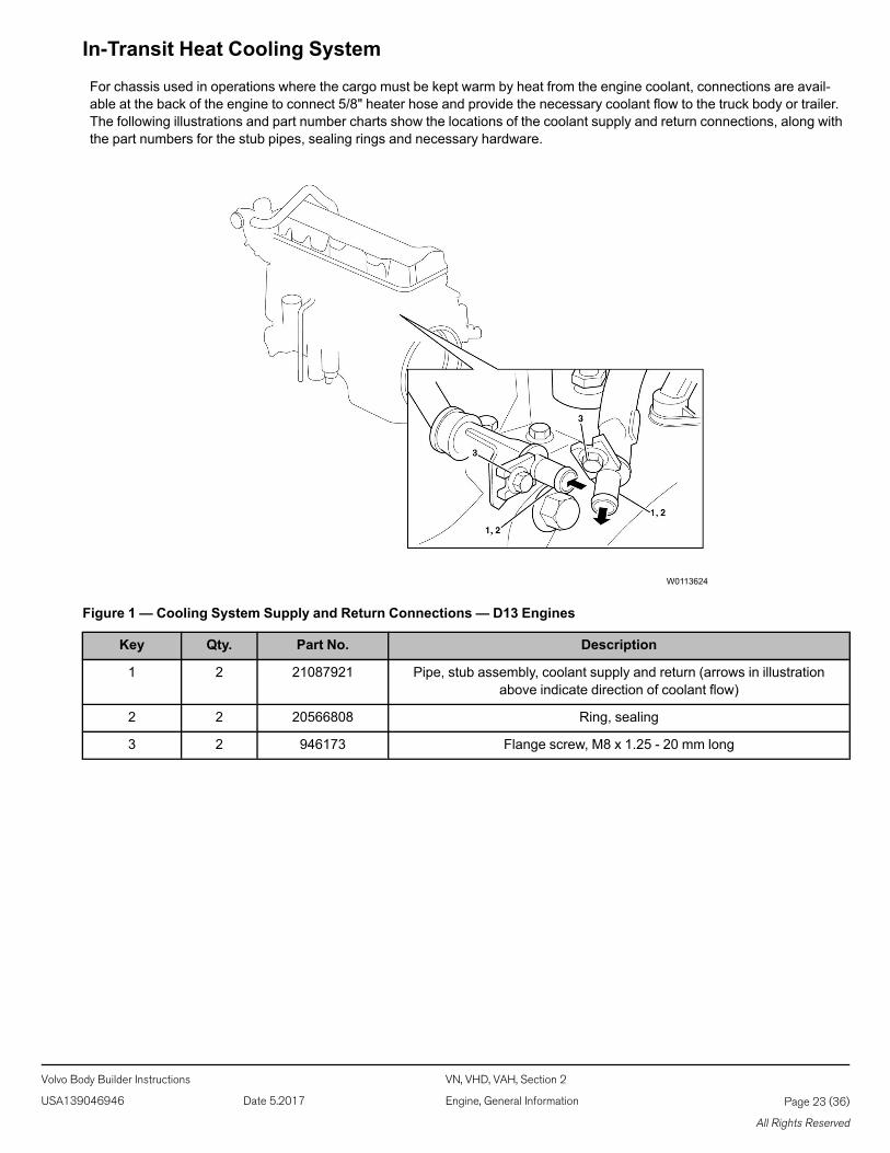
For chassis used in operations where the cargo must be kept warm by heat from the engine coolant, connections are avail-able at the back of the engine to connect 5/8" heater hose and provide the necessary coolant flow to the truck body or trailer.The following illustrations and part number charts show the locations of the coolant supply and return connections, along withthe part numbers for the stub pipes, sealing rings and necessary hardware.
W0113624
Figure 1 — Cooling System Supply and Return Connections — D13 Engines
Key Qty. Part No. Description
1 2 21087921 Pipe, stub assembly, coolant supply and return (arrows in illustrationabove indicate direction of coolant flow)
2 2 20566808 Ring, sealing
3 2 946173 Flange screw, M8 x 1.25 - 20 mm long
Volvo Body Builder Instructions VN, VHD, VAH, Section 2
USA139046946 Date 5.2017 Engine, General Information Page 23 (36)
All Rights Reserved
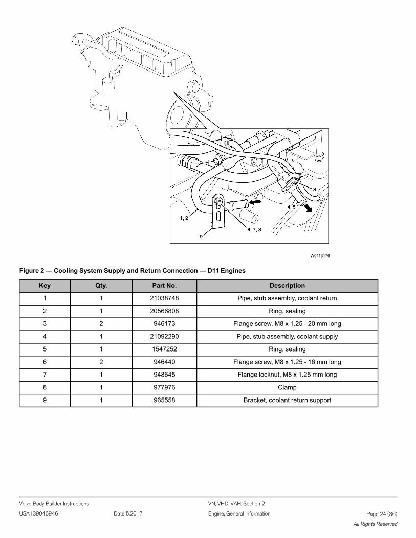
W0113176
Figure 2 — Cooling System Supply and Return Connection — D11 Engines
Key Qty. Part No. Description
1 1 21038748 Pipe, stub assembly, coolant return
2 1 20566808 Ring, sealing
3 2 946173 Flange screw, M8 x 1.25 - 20 mm long
4 1 21092290 Pipe, stub assembly, coolant supply
5 1 1547252 Ring, sealing
6 2 946440 Flange screw, M8 x 1.25 - 16 mm long
7 1 948645 Flange locknut, M8 x 1.25 mm long
8 1 977976 Clamp
9 1 965558 Bracket, coolant return support
Volvo Body Builder Instructions VN, VHD, VAH, Section 2
USA139046946 Date 5.2017 Engine, General Information Page 24 (36)
All Rights Reserved
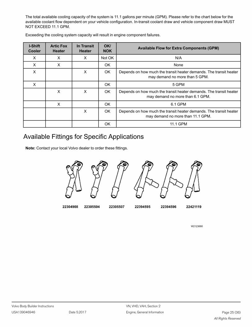
The total available cooling capacity of the system is 11.1 gallons per minute (GPM). Please refer to the chart below for theavailable coolant flow dependent on your vehicle configuration. In-transit coolant draw and vehicle component draw MUSTNOT EXCEED 11.1 GPM.
Exceeding the cooling system capacity will result in engine component failures.
I-ShiftCooler
Artic FoxHeater
In TransitHeater
OK/NOK
Available Flow for Extra Components (GPM)
X X X Not OK N/A
X X OK None
X X OK Depends on how much the transit heater demands. The transit heatermay demand no more than 5 GPM.
X OK 5 GPM
X X OK Depends on how much the transit heater demands. The transit heatermay demand no more than 6.1 GPM.
X OK 6.1 GPM
X OK Depends on how much the transit heater demands. The transit heatermay demand no more than 11.1 GPM.
OK 11.1 GPM
Available Fittings for Specific ApplicationsNote: Contact your local Volvo dealer to order these fittings.
W2123680
Volvo Body Builder Instructions VN, VHD, VAH, Section 2
USA139046946 Date 5.2017 Engine, General Information Page 25 (36)
All Rights Reserved

Smart NOx Sensor
W9000948
The Smart NOx- sensor is used to monitor the emission reduction system. Two NOx sensors are needed for US 2010 ve-hicles. One sensor is positioned on the DPF/muffler outlet, the other on the exhaust pipe after the SCR-muffler for (horizontalversion) or on the SCR-muffler outlet (vertical version).
Note: The Smart NOx sensors should not be moved or modified in anyway. To do so would inhibit the proper operation of theAftertreatment system
Notes
Volvo Body Builder Instructions VN, VHD, VAH, Section 2
USA139046946 Date 5.2017 Engine, General Information Page 26 (36)
All Rights Reserved
Engine OperationEngine Overspeed
This vehicle is equipped with a diesel engine and should not be operated in an area with a concentration of hydrocarbon va-pors (for example gasoline or diesel fuel fumes). Be especially cautious of low-lying or closed-in areas. The vapors may bedrawn into the engine through the air intake and cause the engine to overspeed. Hot carbon and other sparks may comefrom the exhaust system, and cause an explosion and fire.
If the vehicle is in an area where hydrocarbon vapors may be present, shut the engine off immediately if any abnormalitiesare experienced. DO NOT leave it unattended.
DANGER
The diesel engine will operate on any fuel which enters the cylinder, whether it is from the injectors or from the air intakesystem. Therefore, if any solvent is used to flush out the air cleaner element, the engine may overspeed during start-up.Engine damage and serious personal injury or death from burns or explosion can occur.
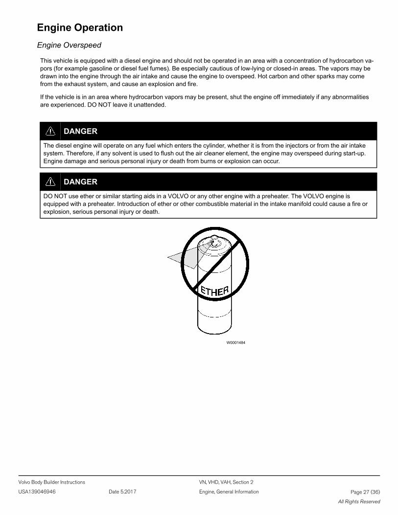
DANGER
DO NOT use ether or similar starting aids in a VOLVO or any other engine with a preheater. The VOLVO engine isequipped with a preheater. Introduction of ether or other combustible material in the intake manifold could cause a fire orexplosion, serious personal injury or death.
W0001484
Volvo Body Builder Instructions VN, VHD, VAH, Section 2
USA139046946 Date 5.2017 Engine, General Information Page 27 (36)
All Rights Reserved
Engine Idling
All VN and VHD model engines are electronically governed engines. The idle speed is pre-programmed from the manufac-turer. Low idle speed is adjustable within certain limits (for most engines between 550 to 700 rpm).
The common belief that idling a diesel engine causes no engine damage is wrong. Idling produces sulfuric acid, whichbreaks down the oil and eats into bearings, rings, valve stems and engine surfaces.
Note: Avoid excessive idling. If the vehicle is parked for more than five minutes, stop the engine. An engine can burn from0.5 to 1.5 gallons (2 to 5.5 liters) of fuel per hour while idling. During long engine idling periods, the engine coolant tempera-ture may fall below the normal operating range*. Incomplete combustion of fuel during the warm-up period can cause dilutionof the oil in the crankcase, formation of lacquer or gummy deposits on the valves, pistons and rings, and rapid accumulationof sludge in the engine.
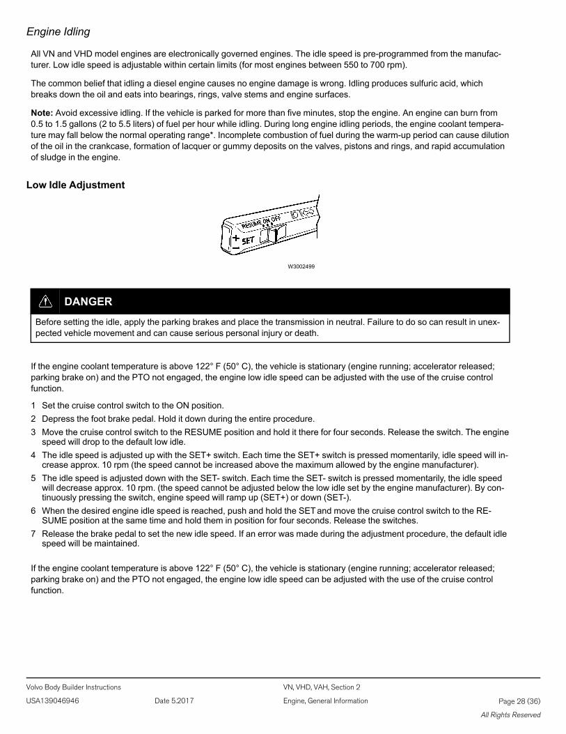
Low Idle Adjustment
W3002499
DANGER
Before setting the idle, apply the parking brakes and place the transmission in neutral. Failure to do so can result in unex-pected vehicle movement and can cause serious personal injury or death.
If the engine coolant temperature is above 122° F (50° C), the vehicle is stationary (engine running; accelerator released;parking brake on) and the PTO not engaged, the engine low idle speed can be adjusted with the use of the cruise controlfunction.
1 Set the cruise control switch to the ON position.2 Depress the foot brake pedal. Hold it down during the entire procedure.3 Move the cruise control switch to the RESUME position and hold it there for four seconds. Release the switch. The engine
speed will drop to the default low idle.4 The idle speed is adjusted up with the SET+ switch. Each time the SET+ switch is pressed momentarily, idle speed will in-
crease approx. 10 rpm (the speed cannot be increased above the maximum allowed by the engine manufacturer).5 The idle speed is adjusted down with the SET- switch. Each time the SET- switch is pressed momentarily, the idle speed
will decrease approx. 10 rpm. (the speed cannot be adjusted below the low idle set by the engine manufacturer). By con-tinuously pressing the switch, engine speed will ramp up (SET+) or down (SET-).
6 When the desired engine idle speed is reached, push and hold the SETand move the cruise control switch to the RE-SUME position at the same time and hold them in position for four seconds. Release the switches.
7 Release the brake pedal to set the new idle speed. If an error was made during the adjustment procedure, the default idlespeed will be maintained.
If the engine coolant temperature is above 122° F (50° C), the vehicle is stationary (engine running; accelerator released;parking brake on) and the PTO not engaged, the engine low idle speed can be adjusted with the use of the cruise controlfunction.
Volvo Body Builder Instructions VN, VHD, VAH, Section 2
USA139046946 Date 5.2017 Engine, General Information Page 28 (36)
All Rights Reserved
Idle Shutdown Timer
The idle shutdown timer can be programmed to shut the engine down after a specific engine idling time. This programmingcannot be changed by the operator and can only be done using special tools. Contact your authorized VOLVO Truck dealerfor details.
The permitted idle time can be set to the following time intervals:
VOLVO – 1 to 40 minutesCummins – 1 to 100 minutesWhen the idle shutdown feature is enabled the engine will shut down at the set time under the following conditions:
• Vehicle speed is 0.
• Engine is running at idle speed.
• Coolant temperature is above 113° F (45° C).
• Parking brake is applied (VOLVO engines only).
These are standard choices when the vehicle is delivered. For more information about other customer adaptation choices,contact your authorized VOLVO Truck dealer.
High Altitude Operation
Engines lose power when operated at high altitude because the air is too thin to allow burning as much fuel as at sea level.For naturally aspirated engines, this loss is about 3% per 1000 feet (300 m) increase in altitude above sea level. Most turbo-charged engines are rated for higher altitudes and will not lose as much power as a naturally aspirated engine.
Closely monitor the gauges during high altitude operation. The thinner ambient air reduces the efficiency of the engine cool-ing system. Engine overheating or cylinder damage could occur if the engine is operated at full load for extended periods athigh altitudes in hot weather. Downshift and reduce vehicle speed to reduce engine load when driving on long grades inthese conditions. This will help keep engine air intake manifold and coolant temperatures within safe limits.
Note: If exhaust smoke is visible during engine operation, this indicates a problem with the exhaust aftertreatment system.Take the vehicle to an authorized VOLVO Truck dealer immediately.
Notes
Volvo Body Builder Instructions VN, VHD, VAH, Section 2
USA139046946 Date 5.2017 Engine, General Information Page 29 (36)
All Rights Reserved
Enhanced Cruise with the VOLVO Enhanced Stability System
Note: For further information on the VOLVO Enhanced Cruise system, including operation and dangers, warnings and cau-tions associated with using this system, refer to VOLVO Enhanced Cruise operator's manual.
VOLVO Enhanced Cruise is integrated with the vehicle's normal cruise control. Once the driver turns "on" and "sets" normalcruise control, VOLVO Enhanced Cruise is automatically engaged.
The VOLVO Enhanced Cruise is an additional integrated feature of your cruise control. When using cruise control, your ve-hicle will now not only maintain the "set" speed, but the system will also intervene, as needed, to help maintain a set followingdistance behind the vehicle in front of your vehicle.
Using a radar sensor (with a range of approximately 500 ft [152 m]) mounted to the front of your vehicle, the VOLVO En-hanced Cruise system reacts to moving vehicles ahead of you.
As a brief introduction, once cruise control is engaged and you are maintaining a set following distance between you and thevehicle in front:
If the vehicle in front of you slows down below your cruise control's set speed, the system will intervene and, as necessary, inthis order:
1 de-throttle the engine,2 apply the engine retarder, and3 apply the foundation brakes,
in an attempt to maintain the set following distance behind the vehicle ahead.
Note: If during the intervention, it is necessary to apply the foundation brakes, the vehicle will not automatically resume tothe set speed.
If the vehicle ahead slows, below your cruise control's set speed, but then accelerates away, and the VOLVO EnhancedCruise system did not need to use the foundation brakes as it managed the intervention, your vehicle will automatically accel-erate back to the original cruise control set speed, and again maintain a set following distance behind any vehicles that areahead of you.
Other system features include a two-stage audible and visual warning system, part of which is always on, whether or not youare using cruise control.
Since the VEC operates along with normal cruise control, all the typical features built into cruise control work as usual. Forexample, limits imposed by factory-set road speed governors, etc. are fully supported by the VEC system.
All vehicles equipped with VOLVO Enhanced Cruise are also equipped with the VOLVO Enhanced Stability System (VEST).VEST is a constantly on, full-stability system which monitors vehicle performance and, when necessary, automatically inter-venes to reduce the throttle and/or applies the foundation brakes to help you maintain stability during potential loss-of-controland/or rollover events. VOLVO Enhanced Cruise uses the VEST to help maintain vehicle stability during automatic brake ap-plications on slick surfaces. Keep in mind that VOLVO Enhanced Cruise should never be used on roads where you cannotdrive safely at a steady speed, including city roads, winding roads, or when road conditions are poor, such as on gravel, dirt,ice or wet surfaces (wet surfaces may increase the risk of hydroplaning), or in fog, heavy rain or snowy conditions. Alwaysswitch off VOLVO Enhanced Cruise when entering turning lanes, entering or exiting highways, driving through constructionzones, or similar situations.
Note: The VEST is always operational when the vehicle is running; the active interventions and select warnings of the VOL-VO Enhanced Cruise are only operational when the cruise control is engaged.
Volvo Body Builder Instructions VN, VHD, VAH, Section 2
USA139046946 Date 5.2017 Engine, General Information Page 30 (36)
All Rights Reserved
VOLVO Enhanced Cruise Components
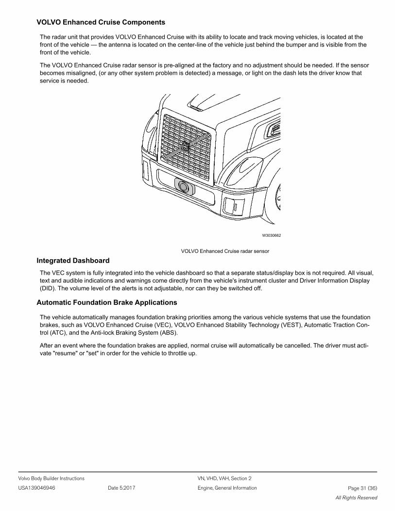
The radar unit that provides VOLVO Enhanced Cruise with its ability to locate and track moving vehicles, is located at thefront of the vehicle — the antenna is located on the center-line of the vehicle just behind the bumper and is visible from thefront of the vehicle.
The VOLVO Enhanced Cruise radar sensor is pre-aligned at the factory and no adjustment should be needed. If the sensorbecomes misaligned, (or any other system problem is detected) a message, or light on the dash lets the driver know thatservice is needed.
W3030662
VOLVO Enhanced Cruise radar sensor
Integrated DashboardThe VEC system is fully integrated into the vehicle dashboard so that a separate status/display box is not required. All visual,text and audible indications and warnings come directly from the vehicle's instrument cluster and Driver Information Display(DID). The volume level of the alerts is not adjustable, nor can they be switched off.
Automatic Foundation Brake Applications
The vehicle automatically manages foundation braking priorities among the various vehicle systems that use the foundationbrakes, such as VOLVO Enhanced Cruise (VEC), VOLVO Enhanced Stability Technology (VEST), Automatic Traction Con-trol (ATC), and the Anti-lock Braking System (ABS).
After an event where the foundation brakes are applied, normal cruise will automatically be cancelled. The driver must acti-vate "resume" or "set" in order for the vehicle to throttle up.
Volvo Body Builder Instructions VN, VHD, VAH, Section 2
USA139046946 Date 5.2017 Engine, General Information Page 31 (36)
All Rights Reserved
Operating the VOLVO Enhanced Cruise
W3031243
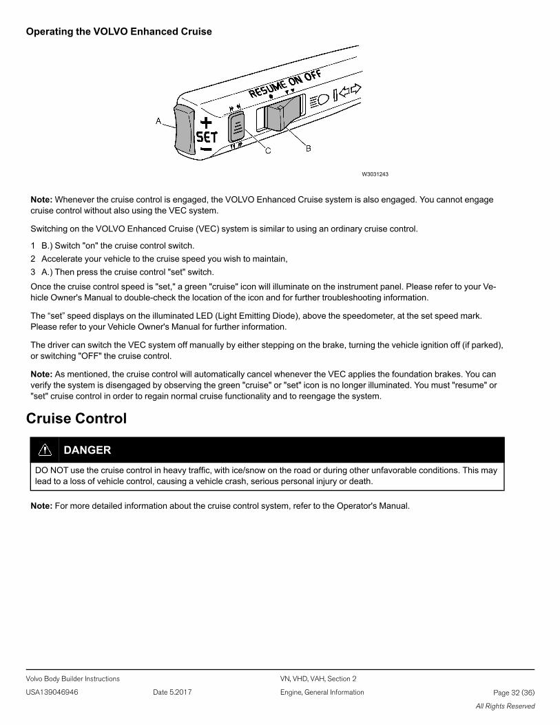
Note:Whenever the cruise control is engaged, the VOLVO Enhanced Cruise system is also engaged. You cannot engagecruise control without also using the VEC system.
Switching on the VOLVO Enhanced Cruise (VEC) system is similar to using an ordinary cruise control.
1 B.) Switch "on" the cruise control switch.2 Accelerate your vehicle to the cruise speed you wish to maintain,3 A.) Then press the cruise control "set" switch.
Once the cruise control speed is "set," a green "cruise" icon will illuminate on the instrument panel. Please refer to your Ve-hicle Owner's Manual to double-check the location of the icon and for further troubleshooting information.
The “set” speed displays on the illuminated LED (Light Emitting Diode), above the speedometer, at the set speed mark.Please refer to your Vehicle Owner's Manual for further information.
The driver can switch the VEC system off manually by either stepping on the brake, turning the vehicle ignition off (if parked),or switching "OFF" the cruise control.
Note: As mentioned, the cruise control will automatically cancel whenever the VEC applies the foundation brakes. You canverify the system is disengaged by observing the green "cruise" or "set" icon is no longer illuminated. You must "resume" or"set" cruise control in order to regain normal cruise functionality and to reengage the system.
Cruise Control
DANGER
DO NOT use the cruise control in heavy traffic, with ice/snow on the road or during other unfavorable conditions. This maylead to a loss of vehicle control, causing a vehicle crash, serious personal injury or death.
Note: For more detailed information about the cruise control system, refer to the Operator's Manual.
Volvo Body Builder Instructions VN, VHD, VAH, Section 2
USA139046946 Date 5.2017 Engine, General Information Page 32 (36)
All Rights Reserved
Engaging
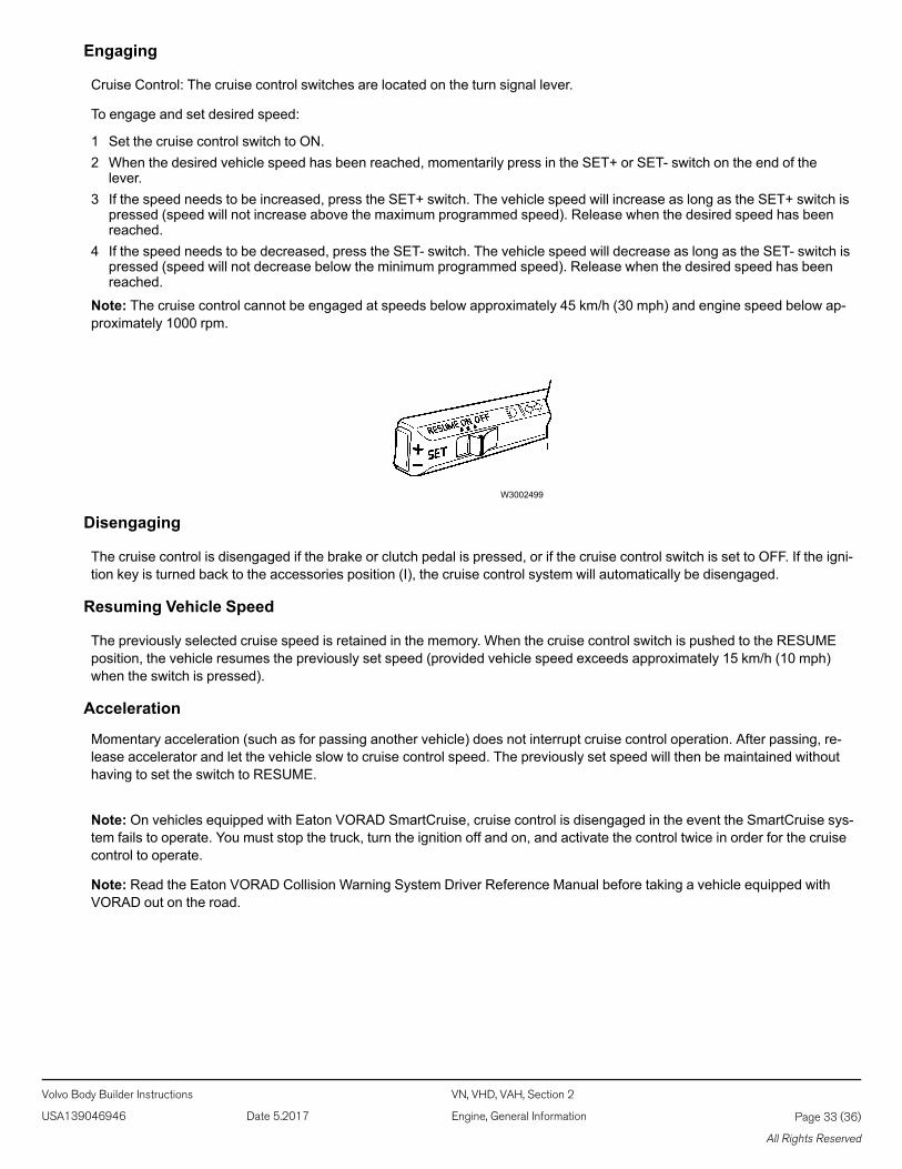
Cruise Control: The cruise control switches are located on the turn signal lever.
To engage and set desired speed:
1 Set the cruise control switch to ON.2 When the desired vehicle speed has been reached, momentarily press in the SET+ or SET- switch on the end of the
lever.3 If the speed needs to be increased, press the SET+ switch. The vehicle speed will increase as long as the SET+ switch is
pressed (speed will not increase above the maximum programmed speed). Release when the desired speed has beenreached.
4 If the speed needs to be decreased, press the SET- switch. The vehicle speed will decrease as long as the SET- switch ispressed (speed will not decrease below the minimum programmed speed). Release when the desired speed has beenreached.
Note: The cruise control cannot be engaged at speeds below approximately 45 km/h (30 mph) and engine speed below ap-proximately 1000 rpm.
W3002499
Disengaging
The cruise control is disengaged if the brake or clutch pedal is pressed, or if the cruise control switch is set to OFF. If the igni-tion key is turned back to the accessories position (I), the cruise control system will automatically be disengaged.
Resuming Vehicle Speed
The previously selected cruise speed is retained in the memory. When the cruise control switch is pushed to the RESUMEposition, the vehicle resumes the previously set speed (provided vehicle speed exceeds approximately 15 km/h (10 mph)when the switch is pressed).
Acceleration
Momentary acceleration (such as for passing another vehicle) does not interrupt cruise control operation. After passing, re-lease accelerator and let the vehicle slow to cruise control speed. The previously set speed will then be maintained withouthaving to set the switch to RESUME.
Note: On vehicles equipped with Eaton VORAD SmartCruise, cruise control is disengaged in the event the SmartCruise sys-tem fails to operate. You must stop the truck, turn the ignition off and on, and activate the control twice in order for the cruisecontrol to operate.
Note: Read the Eaton VORAD Collision Warning System Driver Reference Manual before taking a vehicle equipped withVORAD out on the road.
Volvo Body Builder Instructions VN, VHD, VAH, Section 2
USA139046946 Date 5.2017 Engine, General Information Page 33 (36)
All Rights Reserved

Fittings, Fuel Line, ReplacementThis information covers the proper procedure for replacing the Voss fuel line fittings.
Note: Information is subject to change without notice. Illustrations are used for reference only, and may differ slightly fromthe actual engine version. However, key components addressed in this information are represented as accurately aspossible.
Special Tools
W2006113 W2006115 W2006116W2006114
85111500Voss Pliers
85111501Voss Straight Drift
85111502Voss Elbow Drift
85111503Voss Handle
Fittings
W2006109 W2006110W2006111 W2006112
20395030Straight 16 mm Fitting
20395028Straight 12.5 mm Fitting
2039503490 degree 12.5 mm Fitting
2039503690 degree 16 mm Fitting
Replacement1. After determining which molded Nylon end needs to be replaced, cut the nylon tubing off just behind the barb.
Note:Make a nice clean, square cut.
W2006149
Volvo Body Builder Instructions VN, VHD, VAH, Section 2
USA139046946 Date 5.2017 Engine, General Information Page 34 (36)
All Rights Reserved
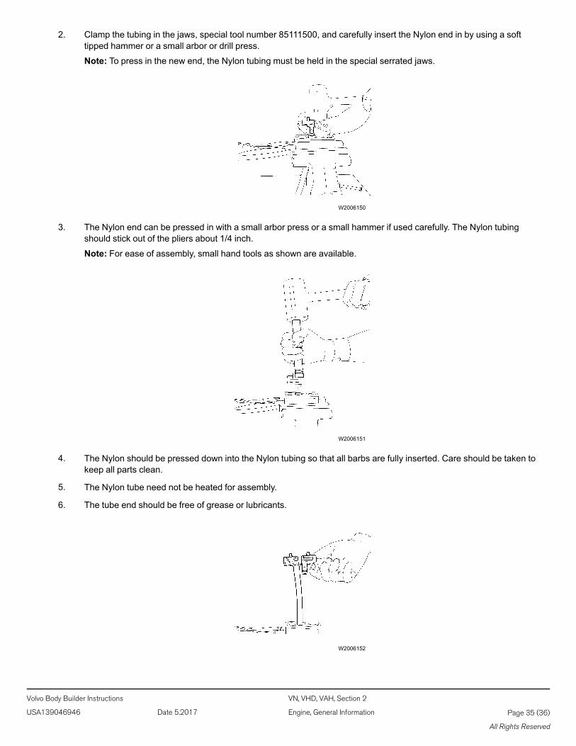
2. Clamp the tubing in the jaws, special tool number 85111500, and carefully insert the Nylon end in by using a softtipped hammer or a small arbor or drill press.
Note: To press in the new end, the Nylon tubing must be held in the special serrated jaws.
W2006150
3. The Nylon end can be pressed in with a small arbor press or a small hammer if used carefully. The Nylon tubingshould stick out of the pliers about 1/4 inch.
Note: For ease of assembly, small hand tools as shown are available.
W2006151
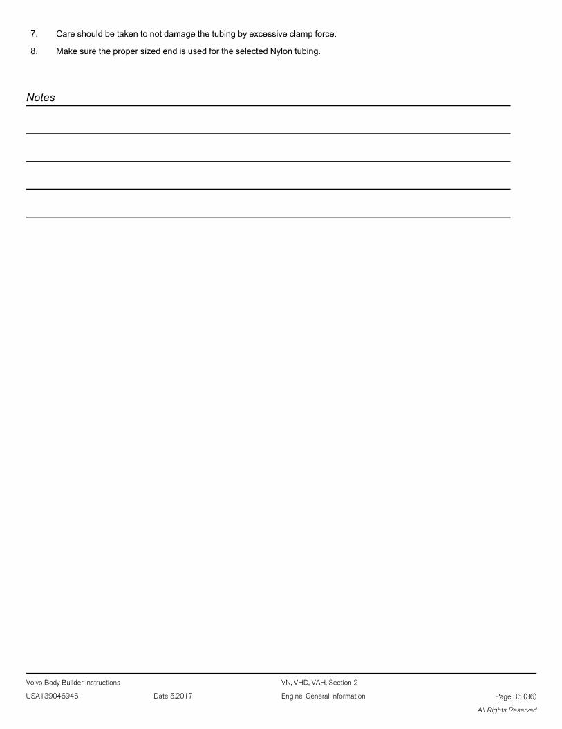
4. The Nylon should be pressed down into the Nylon tubing so that all barbs are fully inserted. Care should be taken tokeep all parts clean.
5. The Nylon tube need not be heated for assembly.
6. The tube end should be free of grease or lubricants.
W2006152
Volvo Body Builder Instructions VN, VHD, VAH, Section 2
USA139046946 Date 5.2017 Engine, General Information Page 35 (36)
All Rights Reserved
7. Care should be taken to not damage the tubing by excessive clamp force.
8. Make sure the proper sized end is used for the selected Nylon tubing.
Notes
Volvo Body Builder Instructions VN, VHD, VAH, Section 2
USA139046946 Date 5.2017 Engine, General Information Page 36 (36)
All Rights Reserved