body builder instructions - mack trucks › - › media › files › body...body builder...
TRANSCRIPT
BODY BUILDER INSTRUCTIONSMack Trucks
Bodybuilder; Brakes and Air SystemsPI / CHU, AN / CXU, GR / GU, TD
LR, TE / MRUSection 5
Introduction
This information provides design and function, specification and procedure details forBrake and Air Systems for MACK vehicles.
Note:We have attempted to cover as much information as possible. However, thisinformation does not cover all the unique variations that a vehicle chassis may present.Note that illustrations are typical but may not reflect all the variations of assembly.
All data provided is based on information that was current at time of release. However,this information is subject to change without notice.
Please note that no part of this information may be reproduced, stored, or transmitted byany means without the express written permission of MACK Trucks, Inc.
Contents:• “Air Brake System”, page 2
• “Air Solenoid Valves”, page 4
• “Liftable Axle Air System Requirements”, page 7
• “Air Lines Joystick Control”, page 15
• “Air Line Hose Installation”, page 16
• “Air Lines Routing”, page 23
• “Air Brake Routing Schematics”, page 34
• “Air Line Numbers and Description”, page 46
• “Air Tank Fittings”, page 52
• “Brake Literature”, page 53
Mack Body Builder Instructions PI / CHU, AN / CXU, GR / GU, TD, LR, TE / MRU
USA141023216 Date 2.2018 Page 1 (54)
All Rights Reserved
Air Brake System
Air Brake System MVSS Requirements
MVSS ComplianceAs manufactured by MACK Trucks, Inc., the air brake system on MACK chassis (both incomplete and complete) comply withthe applicable requirements of U.S. Federal and Canada Motor Vehicle Safety Standards (MVSS) 106, Brake Hoses, and121, Air Brake Systems. Any change or addition to the system may cause the vehicle to no longer be in compliance withthese MVSS.
MVSS 121 requirements cover (but are not limited to) the following:
• Air compressor build-up time
• Air reservoir volume
• Service brake stopping distance
• Brake actuation time
• Brake release time
• Parking brake hold on grades
• Emergency brake stopping distance
For a complete list of certification requirements, refer to U.S. Federal MVSS 121 or Canada MVSS 121. These motor vehiclesafety standards can be accessed at the following web addresses:
• Federal Motor Vehicle Safety Standards https://www.gpo.gov/
• Canada Motor Vehicle Safety Standards http://www.tc.gc.ca/eng/acts-regulations/regulations-crc-c1038.htmIt is the responsibility of the body/equipment installer/alterer to ensure that the MACK vehicle remains in compliance with ap-plicable MVSS. It is also the responsibility of the body/equipment installer/alterer to comply with applicable vehicle certifica-tion regulations.
Air Brake System Truck TractorThere are basic differences between straight truck and truck tractor air systems. On a straight truck, a spring brake controlvalve is added to the emergency brake air circuit. This gives the driver modulated control of the spring brakes through thetreadle valve in the event of a primary system air loss. Additionally, spring brake chambers are installed on both axles of atandem rear axle unit so that if there is a partial air system pressure loss, the emergency brake system will stop the vehiclewithin the required stopping distance, and also to meet parking brake system requirements.
A truck air system is designed to be operated as that of a truck, and a truck tractor air system is designed to be operated asthat of a truck tractor. When converting chassis for use other than as originally intended (e.g., converting a truck tractor to atruck), the air system must also be changed to ensure that the vehicle remains in compliance with MVSS. Contact MACKTrucks, Inc. Product Support for more information.
Mack Body Builder Instructions PI / CHU, AN / CXU, GR / GU, TD, LR, TE / MRU
USA141023216 Date 2.2018 Bodybuilder; Brakes and Air Systems Page 2 (54)
All Rights Reserved
Air-Operated EquipmentAdditional air system capacity may be required for air-powered accessories to operate properly without jeopardizing the in-tegrity of the air brake system. Motor Vehicle Safety Standards (MVSS) 121 requires an air capacity 12 times the total vol-ume of all air brake chambers on the vehicle. For additional information on calculating total air volume and brake chamberrated air volumes, refer to Liftable Axle Air System Requirements section in this bulletin.
If additional air capacity is required, an expansion reservoir should be installed. The reservoir and piping must comply withMVSS.
Note:When making any modifications to the vehicle that involves the addition of air springs (i.e., liftable tag or pusher axleshaving air suspensions), the air springs should be supplied by a pressure protected air source so that the air brake system isprotected (to the setting of the pressure protection valve) against air loss should a leak develop in the auxiliary system.
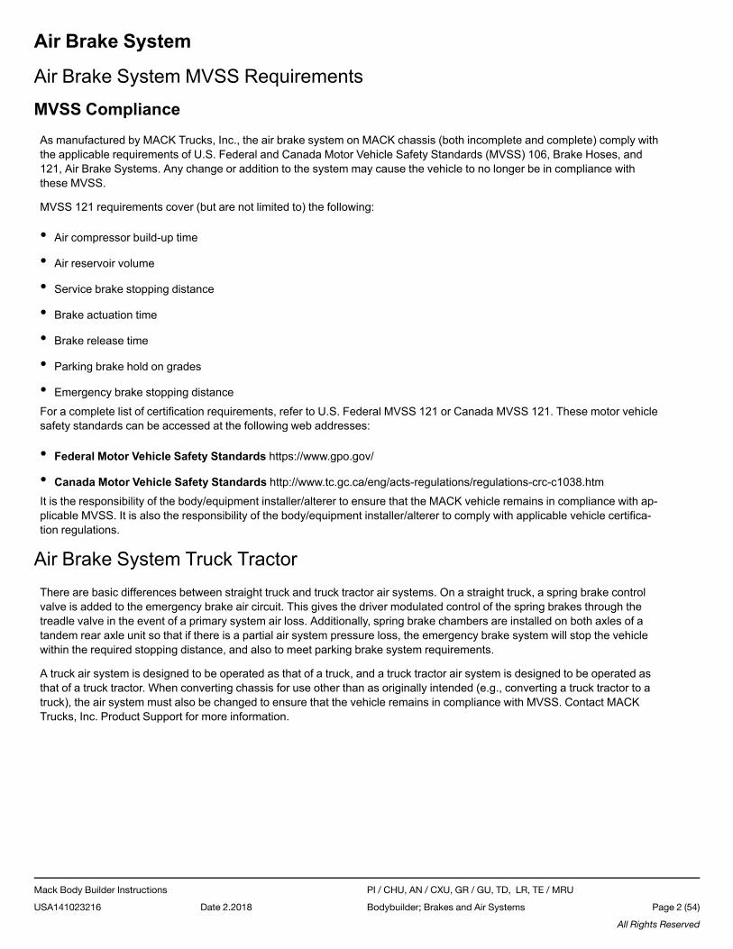
Air Compressor CapacityIf increased air system volume is necessary, it is also necessary to determine if the air compressor has the capacity to supplythe air system without having to run in the loaded mode (compressing) for long periods of time. Motor Vehicle Safety Stand-ards (MVSS) 121 requires that the air compressor must be able to increase pressure in the supply and service (primary andsecondary) reservoirs from 586 – 690 kPa (85 –100 psi), with the engine running at maximum governed RPM, in a specificamount of time, depending on required and actual reservoir capacity. If the existing compressor cannot accomplish this, alarger compressor must be used. First, however, make sure that an air compressor malfunction or other type of problem withthe air system is not causing the slow build-up time.
Build-up time may be calculated as shown.
W5032562
Calculating Air System Build-up Time
Mack Body Builder Instructions PI / CHU, AN / CXU, GR / GU, TD, LR, TE / MRU
USA141023216 Date 2.2018 Bodybuilder; Brakes and Air Systems Page 3 (54)
All Rights Reserved
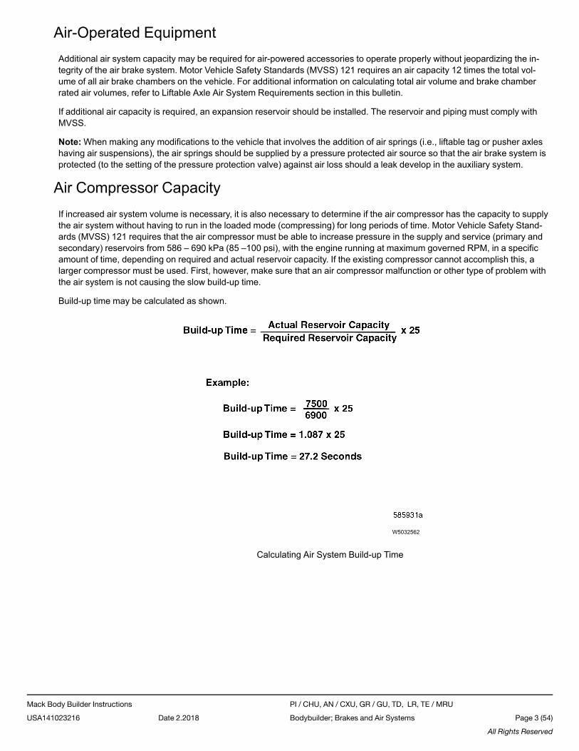
Air Solenoid ValvesMACK chassis now incorporate electrically operated air solenoid valves to direct air pressure to the various accessory air cir-cuits such as air suspension control, fifth wheel slide, inter-axle lockout, power takeoff (PTO), etc. Additional air solenoidvalves can be added to the air solenoid valve pack which is located on the right-hand frame rail, mounted behind the inter-mediate crossmember.
W5032563
Fig. 1 Air Solenoid Valve Pack Location
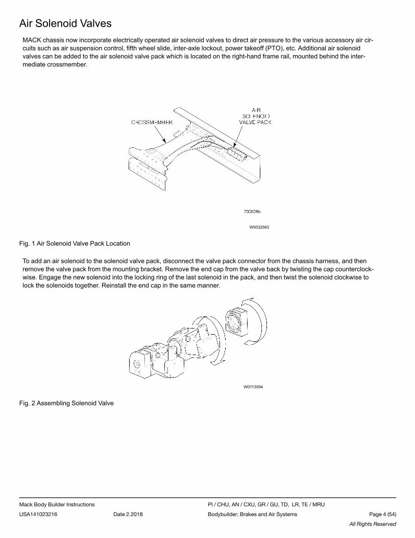
To add an air solenoid to the solenoid valve pack, disconnect the valve pack connector from the chassis harness, and thenremove the valve pack from the mounting bracket. Remove the end cap from the valve back by twisting the cap counterclock-wise. Engage the new solenoid into the locking ring of the last solenoid in the pack, and then twist the solenoid clockwise tolock the solenoids together. Reinstall the end cap in the same manner.
W0113594
Fig. 2 Assembling Solenoid Valve
Mack Body Builder Instructions PI / CHU, AN / CXU, GR / GU, TD, LR, TE / MRU
USA141023216 Date 2.2018 Bodybuilder; Brakes and Air Systems Page 4 (54)
All Rights Reserved
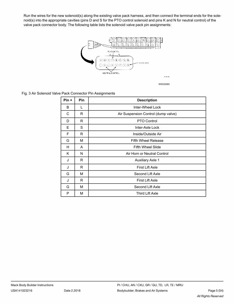
Run the wires for the new solenoid(s) along the existing valve pack harness, and then connect the terminal ends for the sole-noid(s) into the appropriate cavities (pins D and S for the PTO control solenoid and pins K and N for neutral control) of thevalve pack connector body. The following table lists the solenoid valve pack pin assignments:
W5032565
Fig. 3 Air Solenoid Valve Pack Connector Pin Assignments
Pin + Pin Description
B L Inter-Wheel Lock
C R Air Suspension Control (dump valve)
D R PTO Control
E S Inter-Axle Lock
F R Inside/Outside Air
G M Fifth Wheel Release
H A Fifth Wheel Slide
K N Air Horn or Neutral Control
J R Auxiliary Axle 1
J R First Lift Axle
G M Second Lift Axle
J R First Lift Axle
G M Second Lift Axle
P M Third Lift Axle
Mack Body Builder Instructions PI / CHU, AN / CXU, GR / GU, TD, LR, TE / MRU
USA141023216 Date 2.2018 Bodybuilder; Brakes and Air Systems Page 5 (54)
All Rights Reserved
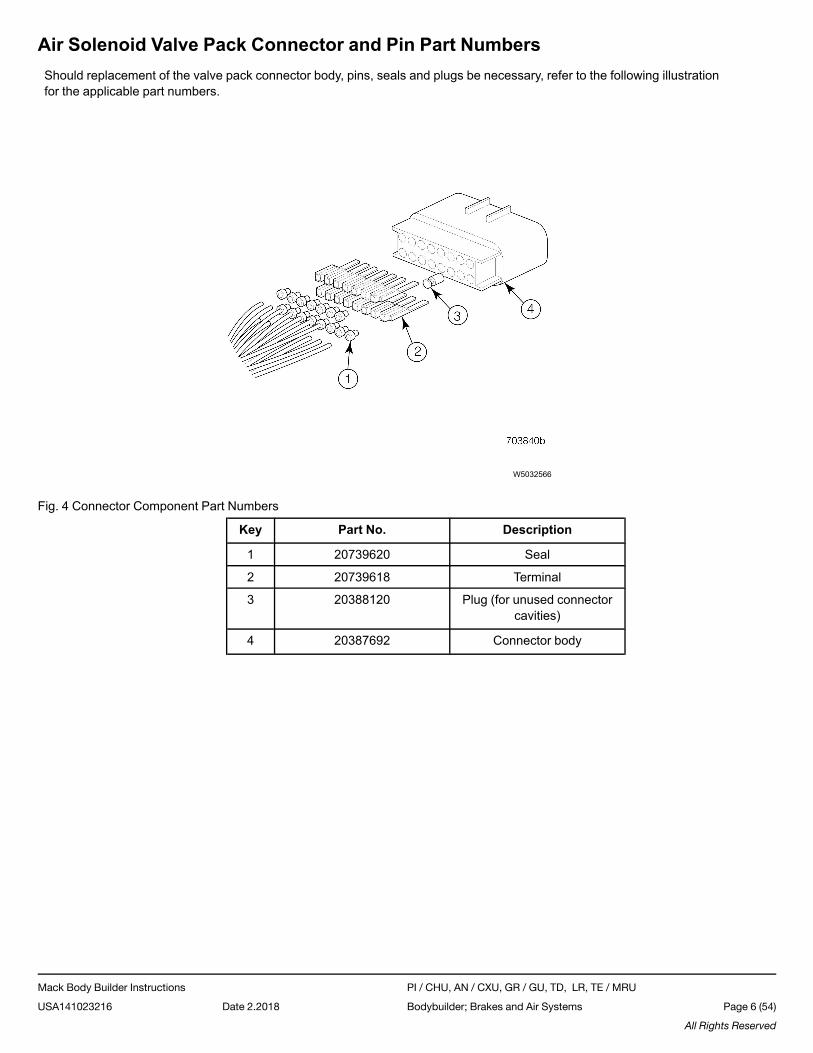
Air Solenoid Valve Pack Connector and Pin Part NumbersShould replacement of the valve pack connector body, pins, seals and plugs be necessary, refer to the following illustrationfor the applicable part numbers.
W5032566
Fig. 4 Connector Component Part Numbers
Key Part No. Description
1 20739620 Seal
2 20739618 Terminal
3 20388120 Plug (for unused connectorcavities)
4 20387692 Connector body
Mack Body Builder Instructions PI / CHU, AN / CXU, GR / GU, TD, LR, TE / MRU
USA141023216 Date 2.2018 Bodybuilder; Brakes and Air Systems Page 6 (54)
All Rights Reserved
Liftable Axle Air System RequirementsInstallation of a liftable axle(s) may require additional air capacity for operation of the service brakes, up/down air bags andsuspension air bags.
Note: The addition of a liftable axle increases the load carrying capacity of the vehicle, which may affect the ability of theparking brake system to hold the vehicle on a hill. Motor Vehicle Safety Standard (MVSS) 121 requires that the parking brakesystem be capable of holding the vehicle under specified conditions. To ensure continued compliance with MVSS 121 whena liftable axle is added, it may be necessary for the installer to increase the capacity of the parking brake system to accountfor the increase in the gross vehicle weight rating (GVWR).
Liftable Axle Air Capacity
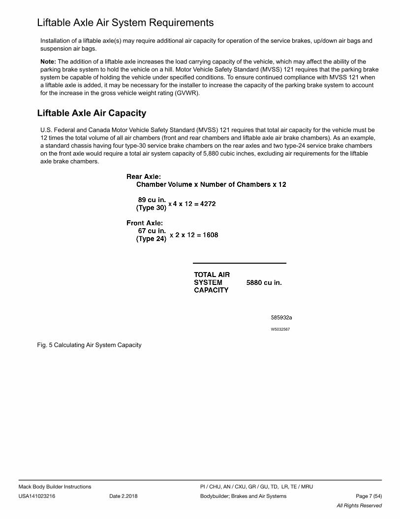
U.S. Federal and Canada Motor Vehicle Safety Standard (MVSS) 121 requires that total air capacity for the vehicle must be12 times the total volume of all air chambers (front and rear chambers and liftable axle air brake chambers). As an example,a standard chassis having four type-30 service brake chambers on the rear axles and two type-24 service brake chamberson the front axle would require a total air system capacity of 5,880 cubic inches, excluding air requirements for the liftableaxle brake chambers.
W5032567
Fig. 5 Calculating Air System Capacity
Mack Body Builder Instructions PI / CHU, AN / CXU, GR / GU, TD, LR, TE / MRU
USA141023216 Date 2.2018 Bodybuilder; Brakes and Air Systems Page 7 (54)
All Rights Reserved
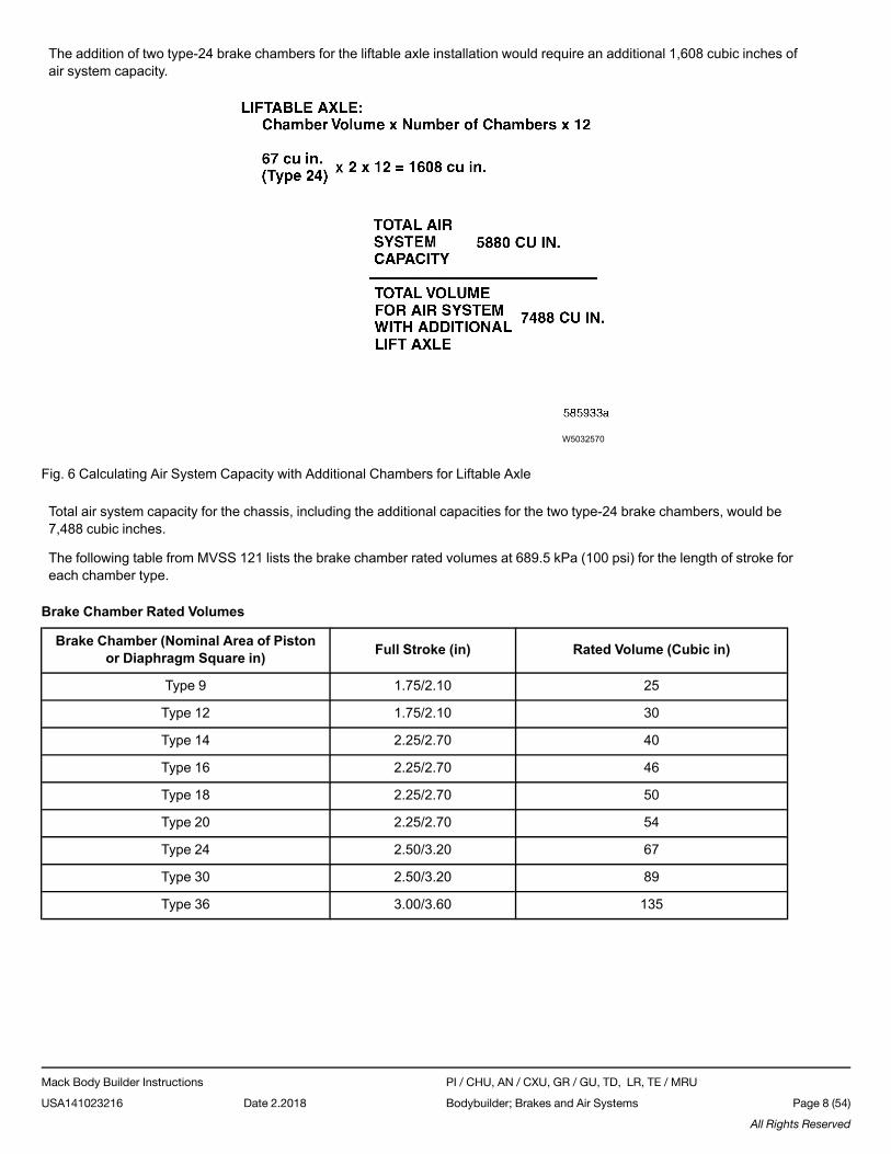
The addition of two type-24 brake chambers for the liftable axle installation would require an additional 1,608 cubic inches ofair system capacity.
W5032570
Fig. 6 Calculating Air System Capacity with Additional Chambers for Liftable Axle
Total air system capacity for the chassis, including the additional capacities for the two type-24 brake chambers, would be7,488 cubic inches.
The following table from MVSS 121 lists the brake chamber rated volumes at 689.5 kPa (100 psi) for the length of stroke foreach chamber type.
Brake Chamber Rated Volumes
Brake Chamber (Nominal Area of Pistonor Diaphragm Square in) Full Stroke (in) Rated Volume (Cubic in)
Type 9 1.75/2.10 25
Type 12 1.75/2.10 30
Type 14 2.25/2.70 40
Type 16 2.25/2.70 46
Type 18 2.25/2.70 50
Type 20 2.25/2.70 54
Type 24 2.50/3.20 67
Type 30 2.50/3.20 89
Type 36 3.00/3.60 135
Mack Body Builder Instructions PI / CHU, AN / CXU, GR / GU, TD, LR, TE / MRU
USA141023216 Date 2.2018 Bodybuilder; Brakes and Air Systems Page 8 (54)
All Rights Reserved
MVSS 121 requires that the combined volume of all service reservoirs and supply reservoirs be at least 12 times the com-bined volume of all service brake chambers. For each brake chamber type having a full stroke at least as great as the firstnumber in Column 1 of the table above, but no more than the second number in Column 1 of the table above, the volume ofeach brake chamber for purposes of calculating the required combined service and supply reservoir volume shall be eitherthat specified in Column 2 of the table above or the actual volume of the brake chamber at maximum travel of the brake pis-ton or push rod, whichever is lower. The volume of a brake chamber not listed in the table above, is the volume of the brakechamber at maximum travel of the brake piston or push rod. The reservoirs of the truck portion of an auto transporter neednot meet this requirement for reservoir volume.
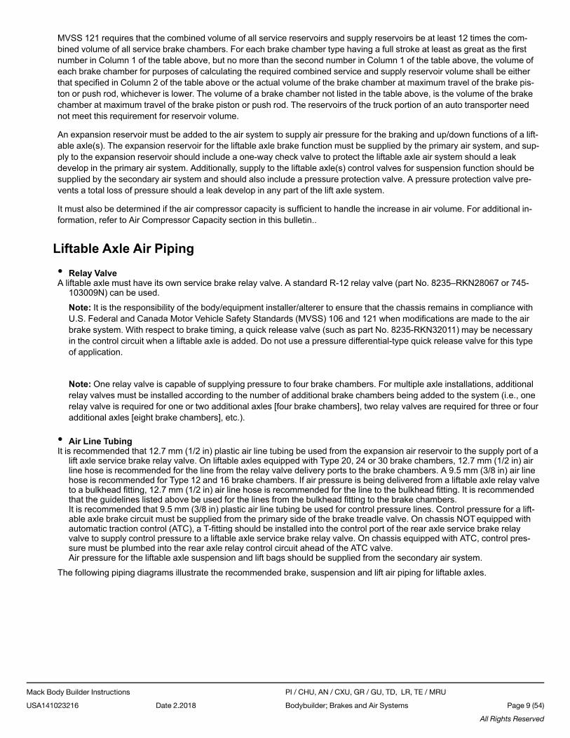
An expansion reservoir must be added to the air system to supply air pressure for the braking and up/down functions of a lift-able axle(s). The expansion reservoir for the liftable axle brake function must be supplied by the primary air system, and sup-ply to the expansion reservoir should include a one-way check valve to protect the liftable axle air system should a leakdevelop in the primary air system. Additionally, supply to the liftable axle(s) control valves for suspension function should besupplied by the secondary air system and should also include a pressure protection valve. A pressure protection valve pre-vents a total loss of pressure should a leak develop in any part of the lift axle system.
It must also be determined if the air compressor capacity is sufficient to handle the increase in air volume. For additional in-formation, refer to Air Compressor Capacity section in this bulletin..
Liftable Axle Air Piping
• Relay ValveA liftable axle must have its own service brake relay valve. A standard R-12 relay valve (part No. 8235–RKN28067 or 745-
103009N) can be used.
Note: It is the responsibility of the body/equipment installer/alterer to ensure that the chassis remains in compliance withU.S. Federal and Canada Motor Vehicle Safety Standards (MVSS) 106 and 121 when modifications are made to the airbrake system. With respect to brake timing, a quick release valve (such as part No. 8235-RKN32011) may be necessaryin the control circuit when a liftable axle is added. Do not use a pressure differential-type quick release valve for this typeof application.
Note: One relay valve is capable of supplying pressure to four brake chambers. For multiple axle installations, additionalrelay valves must be installed according to the number of additional brake chambers being added to the system (i.e., onerelay valve is required for one or two additional axles [four brake chambers], two relay valves are required for three or fouradditional axles [eight brake chambers], etc.).
• Air Line TubingIt is recommended that 12.7 mm (1/2 in) plastic air line tubing be used from the expansion air reservoir to the supply port of a
lift axle service brake relay valve. On liftable axles equipped with Type 20, 24 or 30 brake chambers, 12.7 mm (1/2 in) airline hose is recommended for the line from the relay valve delivery ports to the brake chambers. A 9.5 mm (3/8 in) air linehose is recommended for Type 12 and 16 brake chambers. If air pressure is being delivered from a liftable axle relay valveto a bulkhead fitting, 12.7 mm (1/2 in) air line hose is recommended for the line to the bulkhead fitting. It is recommendedthat the guidelines listed above be used for the lines from the bulkhead fitting to the brake chambers.It is recommended that 9.5 mm (3/8 in) plastic air line tubing be used for control pressure lines. Control pressure for a lift-able axle brake circuit must be supplied from the primary side of the brake treadle valve. On chassis NOTequipped withautomatic traction control (ATC), a T-fitting should be installed into the control port of the rear axle service brake relayvalve to supply control pressure to a liftable axle service brake relay valve. On chassis equipped with ATC, control pres-sure must be plumbed into the rear axle relay control circuit ahead of the ATC valve.Air pressure for the liftable axle suspension and lift bags should be supplied from the secondary air system.
The following piping diagrams illustrate the recommended brake, suspension and lift air piping for liftable axles.
Mack Body Builder Instructions PI / CHU, AN / CXU, GR / GU, TD, LR, TE / MRU
USA141023216 Date 2.2018 Bodybuilder; Brakes and Air Systems Page 9 (54)
All Rights Reserved
W0113590
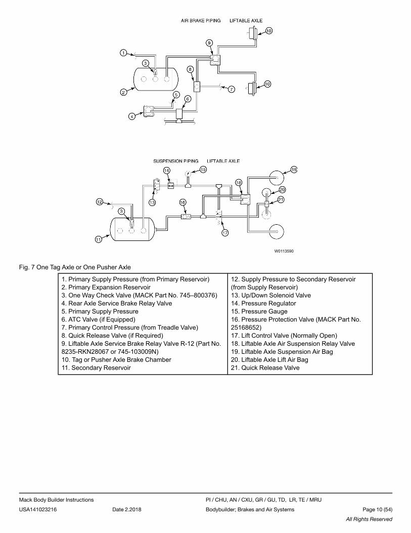
Fig. 7 One Tag Axle or One Pusher Axle
1. Primary Supply Pressure (from Primary Reservoir)2. Primary Expansion Reservoir3. One Way Check Valve (MACK Part No. 745–800376)4. Rear Axle Service Brake Relay Valve5. Primary Supply Pressure6. ATC Valve (if Equipped)7. Primary Control Pressure (from Treadle Valve)8. Quick Release Valve (if Required)9. Liftable Axle Service Brake Relay Valve R-12 (Part No.8235-RKN28067 or 745-103009N)10. Tag or Pusher Axle Brake Chamber11. Secondary Reservoir
12. Supply Pressure to Secondary Reservoir(from Supply Reservoir)13. Up/Down Solenoid Valve14. Pressure Regulator15. Pressure Gauge16. Pressure Protection Valve (MACK Part No.25168652)17. Lift Control Valve (Normally Open)18. Liftable Axle Air Suspension Relay Valve19. Liftable Axle Suspension Air Bag20. Liftable Axle Lift Air Bag21. Quick Release Valve
Mack Body Builder Instructions PI / CHU, AN / CXU, GR / GU, TD, LR, TE / MRU
USA141023216 Date 2.2018 Bodybuilder; Brakes and Air Systems Page 10 (54)
All Rights Reserved
W0113591
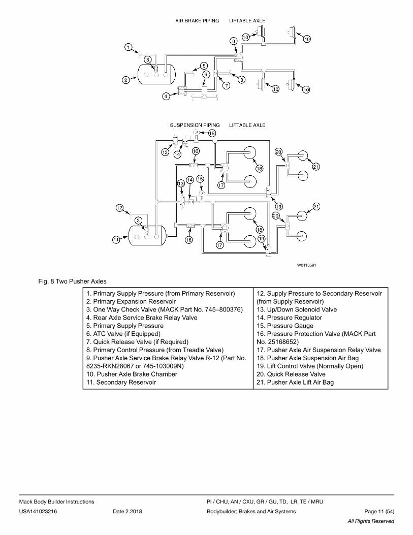
Fig. 8 Two Pusher Axles
1. Primary Supply Pressure (from Primary Reservoir)2. Primary Expansion Reservoir3. One Way Check Valve (MACK Part No. 745–800376)4. Rear Axle Service Brake Relay Valve5. Primary Supply Pressure6. ATC Valve (if Equipped)7. Quick Release Valve (if Required)8. Primary Control Pressure (from Treadle Valve)9. Pusher Axle Service Brake Relay Valve R-12 (Part No.8235-RKN28067 or 745-103009N)10. Pusher Axle Brake Chamber11. Secondary Reservoir
12. Supply Pressure to Secondary Reservoir(from Supply Reservoir)13. Up/Down Solenoid Valve14. Pressure Regulator15. Pressure Gauge16. Pressure Protection Valve (MACK PartNo. 25168652)17. Pusher Axle Air Suspension Relay Valve18. Pusher Axle Suspension Air Bag19. Lift Control Valve (Normally Open)20. Quick Release Valve21. Pusher Axle Lift Air Bag
Mack Body Builder Instructions PI / CHU, AN / CXU, GR / GU, TD, LR, TE / MRU
USA141023216 Date 2.2018 Bodybuilder; Brakes and Air Systems Page 11 (54)
All Rights Reserved
W0113592
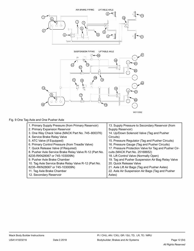
Fig. 9 One Tag Axle and One Pusher Axle
1. Primary Supply Pressure (from Primary Reservoir)2. Primary Expansion Reservoir3. One Way Check Valve (MACK Part No. 745–800376)4. Service Brake Relay Valve5. ATC Valve (if Equipped)6. Primary Control Pressure (from Treadle Valve)7. Quick Release Valve (if Required)8. Pusher Axle Service Brake Relay Valve R-12 (Part No.8235-RKN28067 or 745-103009N)9. Pusher Axle Brake Chamber10. Tag Axle Service Brake Relay Valve R-12 (Part No.8235–RKN28067 or 745-103009N)11. Tag Axle Brake Chamber12. Secondary Reservoir
13. Supply Pressure to Secondary Reservoir (fromSupply Reservoir)14. Up/Down Solenoid Valve (Tag and PusherCircuits)15. Pressure Regulator (Tag and Pusher Circuits)16. Pressure Gauge (Tag and Pusher Circuits)17. Pressure Protection Valve for Tag and Pusher Cir-cuits (MACK Part No. 25168652)18. Lift Control Valve (Normally Open)19. Tag and Pusher Suspension Air Bag Relay Valve20. Quick Release Valve21. Axle Lift Air Bags (Tag and Pusher Axles)22. Axle Air Suspension Air Bags (Tag and PusherAxles)
Mack Body Builder Instructions PI / CHU, AN / CXU, GR / GU, TD, LR, TE / MRU
USA141023216 Date 2.2018 Bodybuilder; Brakes and Air Systems Page 12 (54)
All Rights Reserved
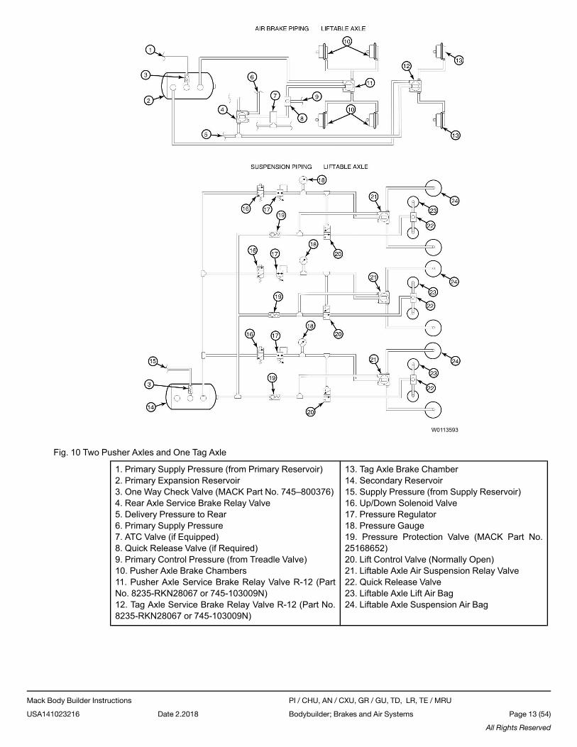
W0113593
Fig. 10 Two Pusher Axles and One Tag Axle
1. Primary Supply Pressure (from Primary Reservoir)2. Primary Expansion Reservoir3. One Way Check Valve (MACK Part No. 745–800376)4. Rear Axle Service Brake Relay Valve5. Delivery Pressure to Rear6. Primary Supply Pressure7. ATC Valve (if Equipped)8. Quick Release Valve (if Required)9. Primary Control Pressure (from Treadle Valve)10. Pusher Axle Brake Chambers11. Pusher Axle Service Brake Relay Valve R-12 (PartNo. 8235-RKN28067 or 745-103009N)12. Tag Axle Service Brake Relay Valve R-12 (Part No.8235-RKN28067 or 745-103009N)
13. Tag Axle Brake Chamber14. Secondary Reservoir15. Supply Pressure (from Supply Reservoir)16. Up/Down Solenoid Valve17. Pressure Regulator18. Pressure Gauge19. Pressure Protection Valve (MACK Part No.25168652)20. Lift Control Valve (Normally Open)21. Liftable Axle Air Suspension Relay Valve22. Quick Release Valve23. Liftable Axle Lift Air Bag24. Liftable Axle Suspension Air Bag
Mack Body Builder Instructions PI / CHU, AN / CXU, GR / GU, TD, LR, TE / MRU
USA141023216 Date 2.2018 Bodybuilder; Brakes and Air Systems Page 13 (54)
All Rights Reserved
Liftable Axle Anti-Lock Brakes
CAUTION
If liftable axles (tags or pushers) are being added to a chassis equipped with the MACK Road Stability Advantage (RSA)system, and it is desired to keep the RSA system active, the liftable axle(s) must be self-steer type axles. The self-steer lift-able axle(s) service brakes MUST NOT be activated by modulated air pressure from the anti-lock brake system. Currently,the only chassis having the RSA system approved for adding self-steer liftable axles are chassis used in concrete mixerand heavy-haul tractor applications.
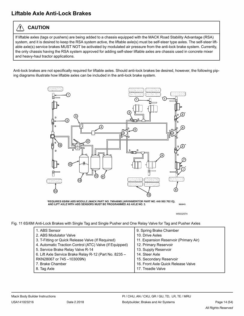
Anti-lock brakes are not specifically required for liftable axles. Should anti-lock brakes be desired, however, the following pip-ing diagrams illustrate how liftable axles can be included in the anti-lock brake system.
W5032574
Fig. 11 6S/6M Anti-Lock Brakes with Single Tag and Single Pusher and One Relay Valve for Tag and Pusher Axles
1. ABS Sensor2. ABS Modulator Valve3. T-Fitting or Quick Release Valve (If Required)4. Automatic Traction Control (ATC) Valve (If Equipped)5. Service Brake Relay Valve R-146. Lift Axle Service Brake Relay R-12 (Part No. 8235 –RKN28067 or 745 –103009N)7. Brake Chamber8. Tag Axle
9. Spring Brake Chamber10. Drive Axles11. Expansion Reservoir (Primary Air)12. Primary Reservoir13. Supply Reservoir14. Steer Axle15. Secondary Reservoir16. Front Axle Quick Release Valve17. Treadle Valve
Mack Body Builder Instructions PI / CHU, AN / CXU, GR / GU, TD, LR, TE / MRU
USA141023216 Date 2.2018 Bodybuilder; Brakes and Air Systems Page 14 (54)
All Rights Reserved
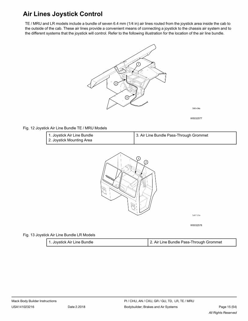
Air Lines Joystick ControlTE / MRU and LR models include a bundle of seven 6.4 mm (1/4 in) air lines routed from the joystick area inside the cab tothe outside of the cab. These air lines provide a convenient means of connecting a joystick to the chassis air system and tothe different systems that the joystick will control. Refer to the following illustration for the location of the air line bundle.
W5032577
Fig. 12 Joystick Air Line Bundle TE / MRU Models
1. Joystick Air Line Bundle2. Joystick Mounting Area
3. Air Line Bundle Pass-Through Grommet
W5032578
Fig. 13 Joystick Air Line Bundle LR Models
1. Joystick Air Line Bundle 2. Air Line Bundle Pass-Through Grommet
Mack Body Builder Instructions PI / CHU, AN / CXU, GR / GU, TD, LR, TE / MRU
USA141023216 Date 2.2018 Bodybuilder; Brakes and Air Systems Page 15 (54)
All Rights Reserved
Air Line Hose InstallationFlexible air line hose may eventually fail. However, by following proper installation, clamping and routing procedures, hoselife can be maximized. Also, when selecting an air line hose, make sure that the hose is the same diameter as the hose beingreplaced. Replacing an air line hose with a different size hose may affect brake timing.
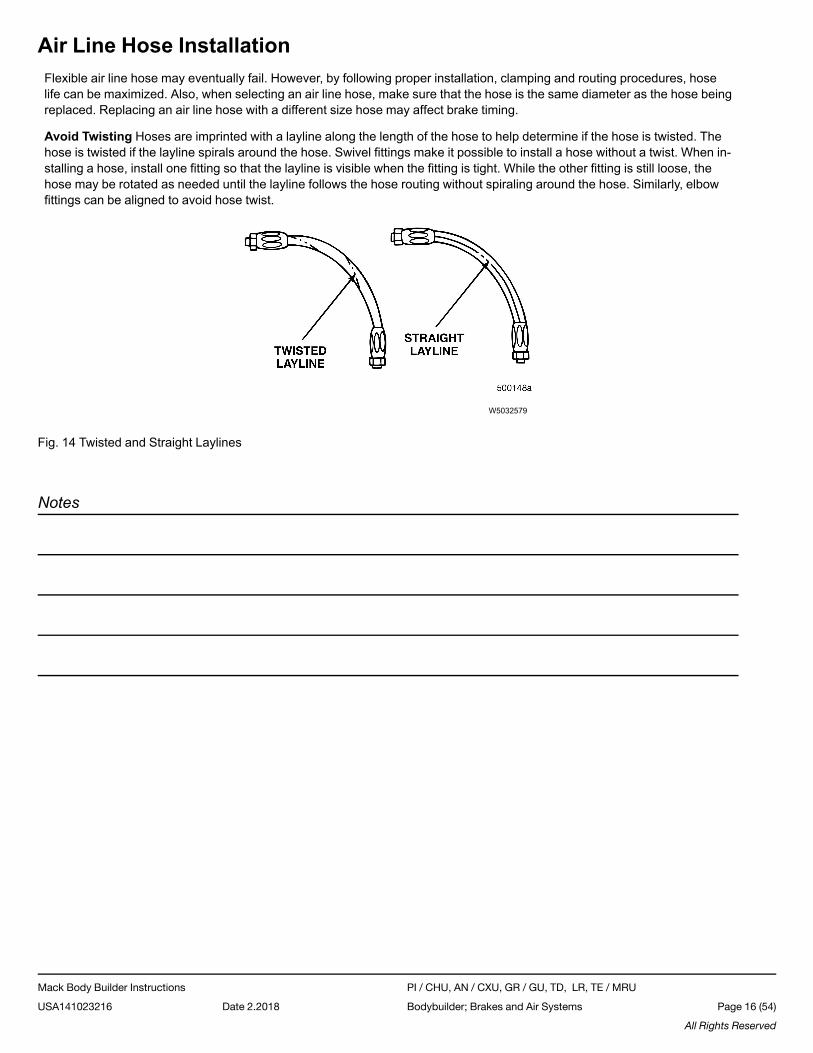
Avoid Twisting Hoses are imprinted with a layline along the length of the hose to help determine if the hose is twisted. Thehose is twisted if the layline spirals around the hose. Swivel fittings make it possible to install a hose without a twist. When in-stalling a hose, install one fitting so that the layline is visible when the fitting is tight. While the other fitting is still loose, thehose may be rotated as needed until the layline follows the hose routing without spiraling around the hose. Similarly, elbowfittings can be aligned to avoid hose twist.
W5032579
Fig. 14 Twisted and Straight Laylines
Notes
Mack Body Builder Instructions PI / CHU, AN / CXU, GR / GU, TD, LR, TE / MRU
USA141023216 Date 2.2018 Bodybuilder; Brakes and Air Systems Page 16 (54)
All Rights Reserved
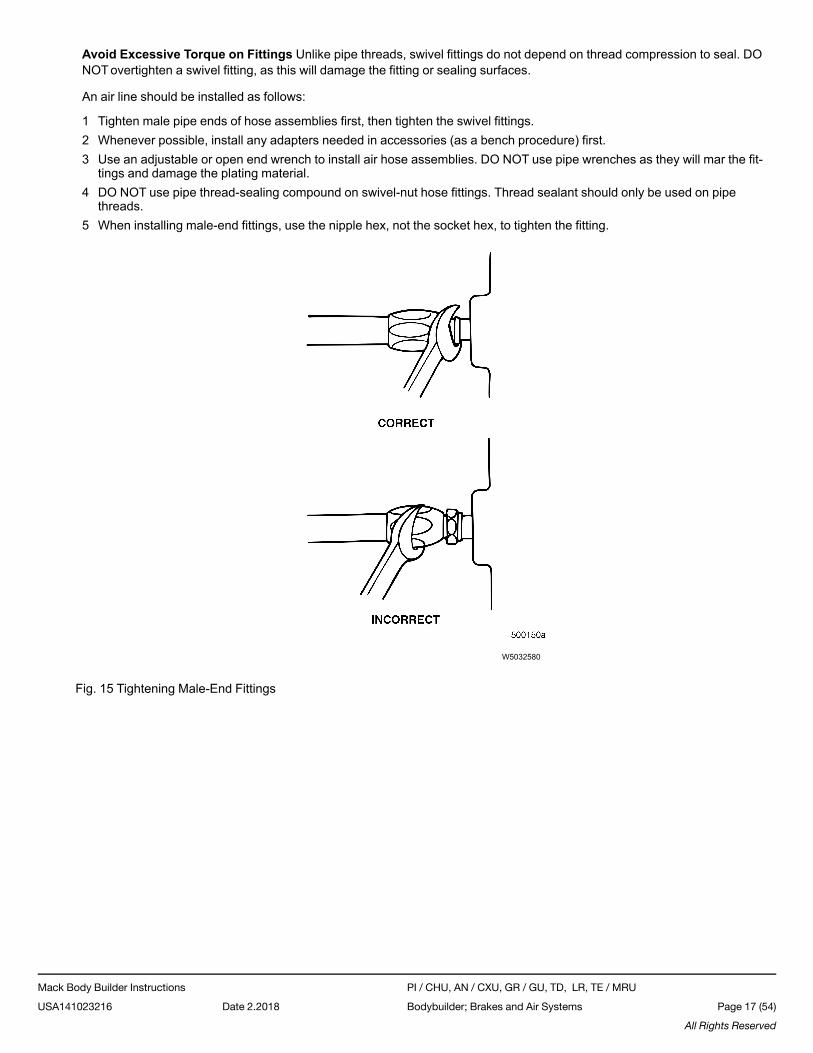
Avoid Excessive Torque on Fittings Unlike pipe threads, swivel fittings do not depend on thread compression to seal. DONOTovertighten a swivel fitting, as this will damage the fitting or sealing surfaces.
An air line should be installed as follows:
1 Tighten male pipe ends of hose assemblies first, then tighten the swivel fittings.2 Whenever possible, install any adapters needed in accessories (as a bench procedure) first.3 Use an adjustable or open end wrench to install air hose assemblies. DO NOT use pipe wrenches as they will mar the fit-
tings and damage the plating material.4 DO NOT use pipe thread-sealing compound on swivel-nut hose fittings. Thread sealant should only be used on pipe
threads.5 When installing male-end fittings, use the nipple hex, not the socket hex, to tighten the fitting.
W5032580
Fig. 15 Tightening Male-End Fittings
Mack Body Builder Instructions PI / CHU, AN / CXU, GR / GU, TD, LR, TE / MRU
USA141023216 Date 2.2018 Bodybuilder; Brakes and Air Systems Page 17 (54)
All Rights Reserved
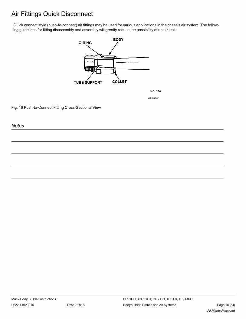
Air Fittings Quick DisconnectQuick connect style (push-to-connect) air fittings may be used for various applications in the chassis air system. The follow-ing guidelines for fitting disassembly and assembly will greatly reduce the possibility of an air leak.
W5032581
Fig. 16 Push-to-Connect Fitting Cross-Sectional View
Notes
Mack Body Builder Instructions PI / CHU, AN / CXU, GR / GU, TD, LR, TE / MRU
USA141023216 Date 2.2018 Bodybuilder; Brakes and Air Systems Page 18 (54)
All Rights Reserved
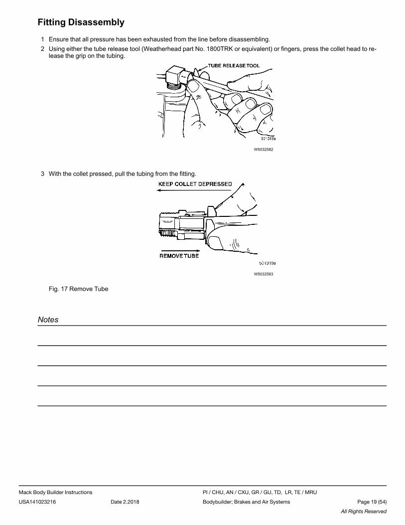
Fitting Disassembly
1 Ensure that all pressure has been exhausted from the line before disassembling.2 Using either the tube release tool (Weatherhead part No. 1800TRK or equivalent) or fingers, press the collet head to re-
lease the grip on the tubing.
W5032582
3 With the collet pressed, pull the tubing from the fitting.
W5032583
Fig. 17 Remove Tube
Notes
Mack Body Builder Instructions PI / CHU, AN / CXU, GR / GU, TD, LR, TE / MRU
USA141023216 Date 2.2018 Bodybuilder; Brakes and Air Systems Page 19 (54)
All Rights Reserved
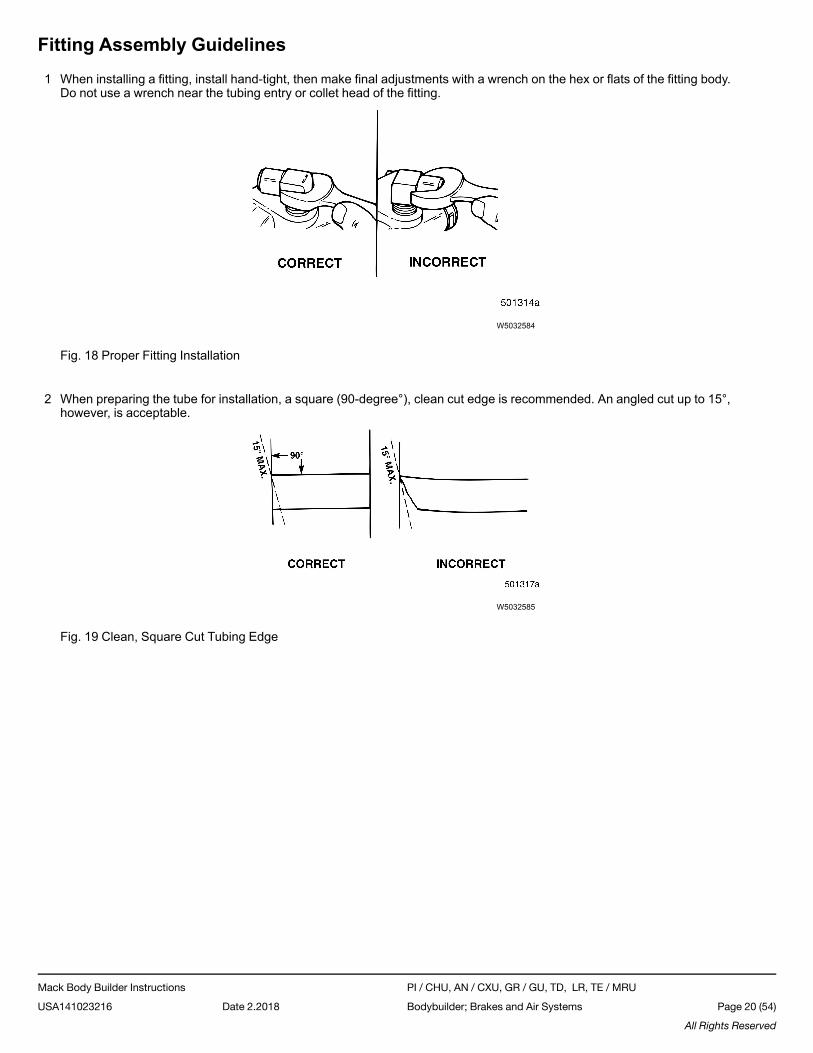
Fitting Assembly Guidelines
1 When installing a fitting, install hand-tight, then make final adjustments with a wrench on the hex or flats of the fitting body.Do not use a wrench near the tubing entry or collet head of the fitting.
W5032584
Fig. 18 Proper Fitting Installation
2 When preparing the tube for installation, a square (90-degree°), clean cut edge is recommended. An angled cut up to 15°,however, is acceptable.
W5032585
Fig. 19 Clean, Square Cut Tubing Edge
Mack Body Builder Instructions PI / CHU, AN / CXU, GR / GU, TD, LR, TE / MRU
USA141023216 Date 2.2018 Bodybuilder; Brakes and Air Systems Page 20 (54)
All Rights Reserved
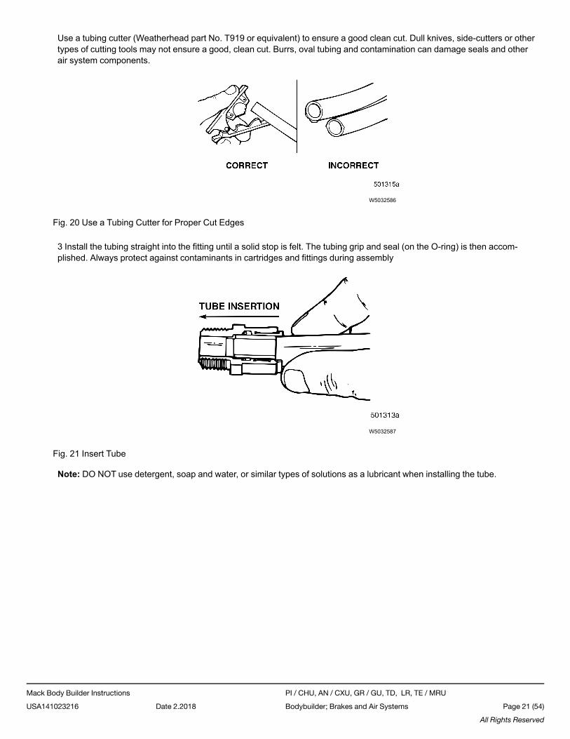
Use a tubing cutter (Weatherhead part No. T919 or equivalent) to ensure a good clean cut. Dull knives, side-cutters or othertypes of cutting tools may not ensure a good, clean cut. Burrs, oval tubing and contamination can damage seals and otherair system components.
W5032586
Fig. 20 Use a Tubing Cutter for Proper Cut Edges
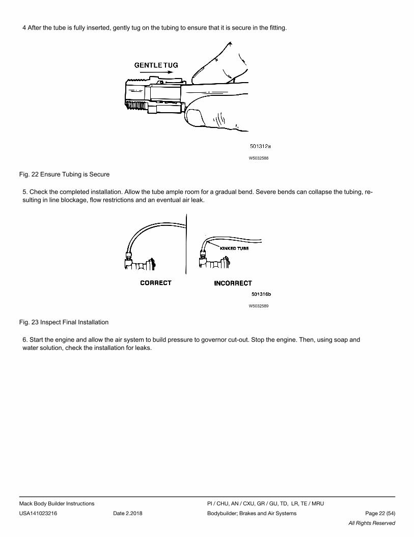
3 Install the tubing straight into the fitting until a solid stop is felt. The tubing grip and seal (on the O-ring) is then accom-plished. Always protect against contaminants in cartridges and fittings during assembly
W5032587
Fig. 21 Insert Tube
Note: DO NOT use detergent, soap and water, or similar types of solutions as a lubricant when installing the tube.
Mack Body Builder Instructions PI / CHU, AN / CXU, GR / GU, TD, LR, TE / MRU
USA141023216 Date 2.2018 Bodybuilder; Brakes and Air Systems Page 21 (54)
All Rights Reserved
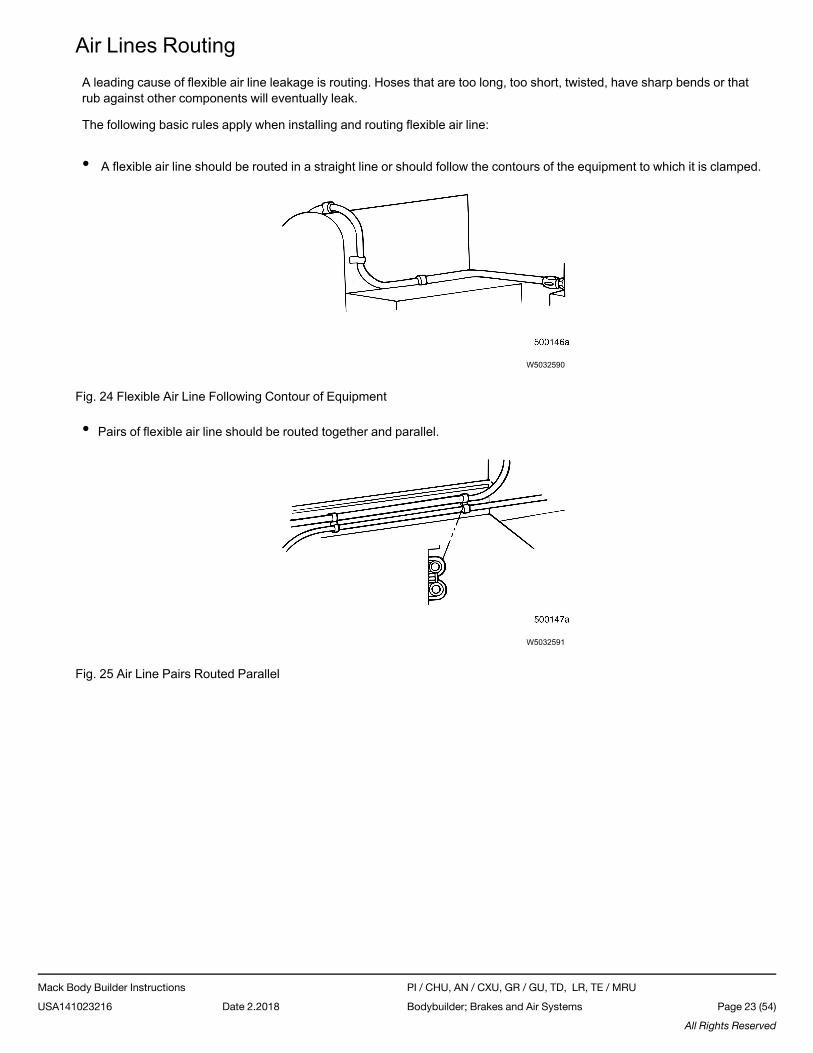
4 After the tube is fully inserted, gently tug on the tubing to ensure that it is secure in the fitting.
W5032588
Fig. 22 Ensure Tubing is Secure
5. Check the completed installation. Allow the tube ample room for a gradual bend. Severe bends can collapse the tubing, re-sulting in line blockage, flow restrictions and an eventual air leak.
W5032589
Fig. 23 Inspect Final Installation
6. Start the engine and allow the air system to build pressure to governor cut-out. Stop the engine. Then, using soap andwater solution, check the installation for leaks.
Mack Body Builder Instructions PI / CHU, AN / CXU, GR / GU, TD, LR, TE / MRU
USA141023216 Date 2.2018 Bodybuilder; Brakes and Air Systems Page 22 (54)
All Rights Reserved
Air Lines RoutingA leading cause of flexible air line leakage is routing. Hoses that are too long, too short, twisted, have sharp bends or thatrub against other components will eventually leak.
The following basic rules apply when installing and routing flexible air line:
• A flexible air line should be routed in a straight line or should follow the contours of the equipment to which it is clamped.
W5032590
Fig. 24 Flexible Air Line Following Contour of Equipment
• Pairs of flexible air line should be routed together and parallel.
W5032591
Fig. 25 Air Line Pairs Routed Parallel
Mack Body Builder Instructions PI / CHU, AN / CXU, GR / GU, TD, LR, TE / MRU
USA141023216 Date 2.2018 Bodybuilder; Brakes and Air Systems Page 23 (54)
All Rights Reserved
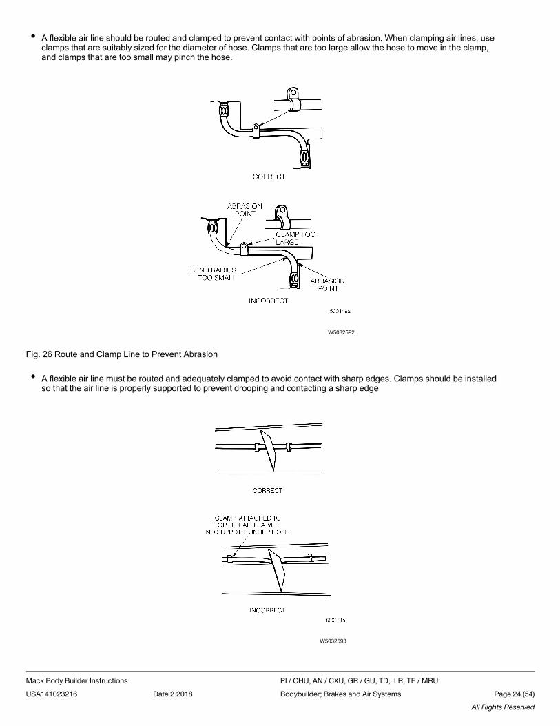
• A flexible air line should be routed and clamped to prevent contact with points of abrasion. When clamping air lines, useclamps that are suitably sized for the diameter of hose. Clamps that are too large allow the hose to move in the clamp,and clamps that are too small may pinch the hose.
W5032592
Fig. 26 Route and Clamp Line to Prevent Abrasion
• A flexible air line must be routed and adequately clamped to avoid contact with sharp edges. Clamps should be installedso that the air line is properly supported to prevent drooping and contacting a sharp edge
W5032593
Mack Body Builder Instructions PI / CHU, AN / CXU, GR / GU, TD, LR, TE / MRU
USA141023216 Date 2.2018 Bodybuilder; Brakes and Air Systems Page 24 (54)
All Rights Reserved
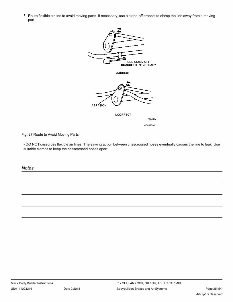
• Route flexible air line to avoid moving parts. If necessary, use a stand-off bracket to clamp the line away from a movingpart.
W5032594
Fig. 27 Route to Avoid Moving Parts
• DO NOTcrisscross flexible air lines. The sawing action between crisscrossed hoses eventually causes the line to leak. Usesuitable clamps to keep the crisscrossed hoses apart.
Notes
Mack Body Builder Instructions PI / CHU, AN / CXU, GR / GU, TD, LR, TE / MRU
USA141023216 Date 2.2018 Bodybuilder; Brakes and Air Systems Page 25 (54)
All Rights Reserved
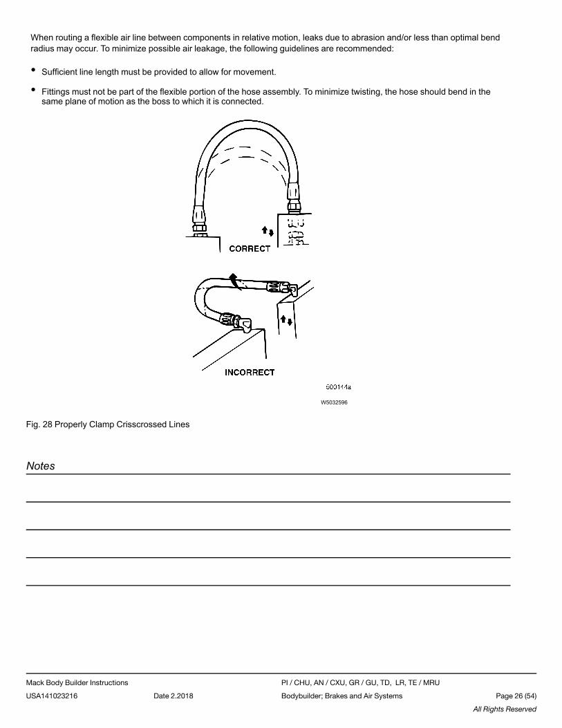
When routing a flexible air line between components in relative motion, leaks due to abrasion and/or less than optimal bendradius may occur. To minimize possible air leakage, the following guidelines are recommended:
• Sufficient line length must be provided to allow for movement.
• Fittings must not be part of the flexible portion of the hose assembly. To minimize twisting, the hose should bend in thesame plane of motion as the boss to which it is connected.
W5032596
Fig. 28 Properly Clamp Crisscrossed Lines
Notes
Mack Body Builder Instructions PI / CHU, AN / CXU, GR / GU, TD, LR, TE / MRU
USA141023216 Date 2.2018 Bodybuilder; Brakes and Air Systems Page 26 (54)
All Rights Reserved
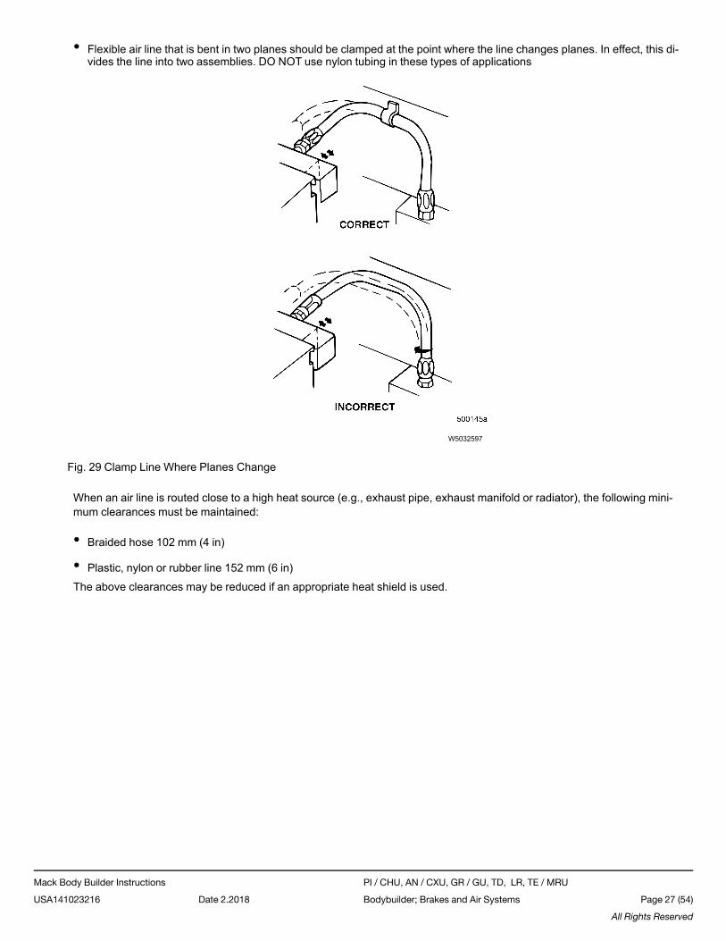
• Flexible air line that is bent in two planes should be clamped at the point where the line changes planes. In effect, this di-vides the line into two assemblies. DO NOT use nylon tubing in these types of applications
W5032597
Fig. 29 Clamp Line Where Planes Change
When an air line is routed close to a high heat source (e.g., exhaust pipe, exhaust manifold or radiator), the following mini-mum clearances must be maintained:
• Braided hose 102 mm (4 in)
• Plastic, nylon or rubber line 152 mm (6 in)
The above clearances may be reduced if an appropriate heat shield is used.
Mack Body Builder Instructions PI / CHU, AN / CXU, GR / GU, TD, LR, TE / MRU
USA141023216 Date 2.2018 Bodybuilder; Brakes and Air Systems Page 27 (54)
All Rights Reserved
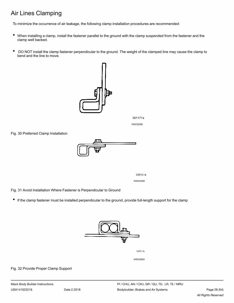
Air Lines ClampingTo minimize the occurrence of air leakage, the following clamp installation procedures are recommended:
• When installing a clamp, install the fastener parallel to the ground with the clamp suspended from the fastener and theclamp well backed.
• DO NOT install the clamp fastener perpendicular to the ground. The weight of the clamped line may cause the clamp tobend and the line to move.
W5032598
Fig. 30 Preferred Clamp Installation
W5032599
Fig. 31 Avoid Installation Where Fastener is Perpendicular to Ground
• If the clamp fastener must be installed perpendicular to the ground, provide full-length support for the clamp
W5032600
Fig. 32 Provide Proper Clamp Support
Mack Body Builder Instructions PI / CHU, AN / CXU, GR / GU, TD, LR, TE / MRU
USA141023216 Date 2.2018 Bodybuilder; Brakes and Air Systems Page 28 (54)
All Rights Reserved
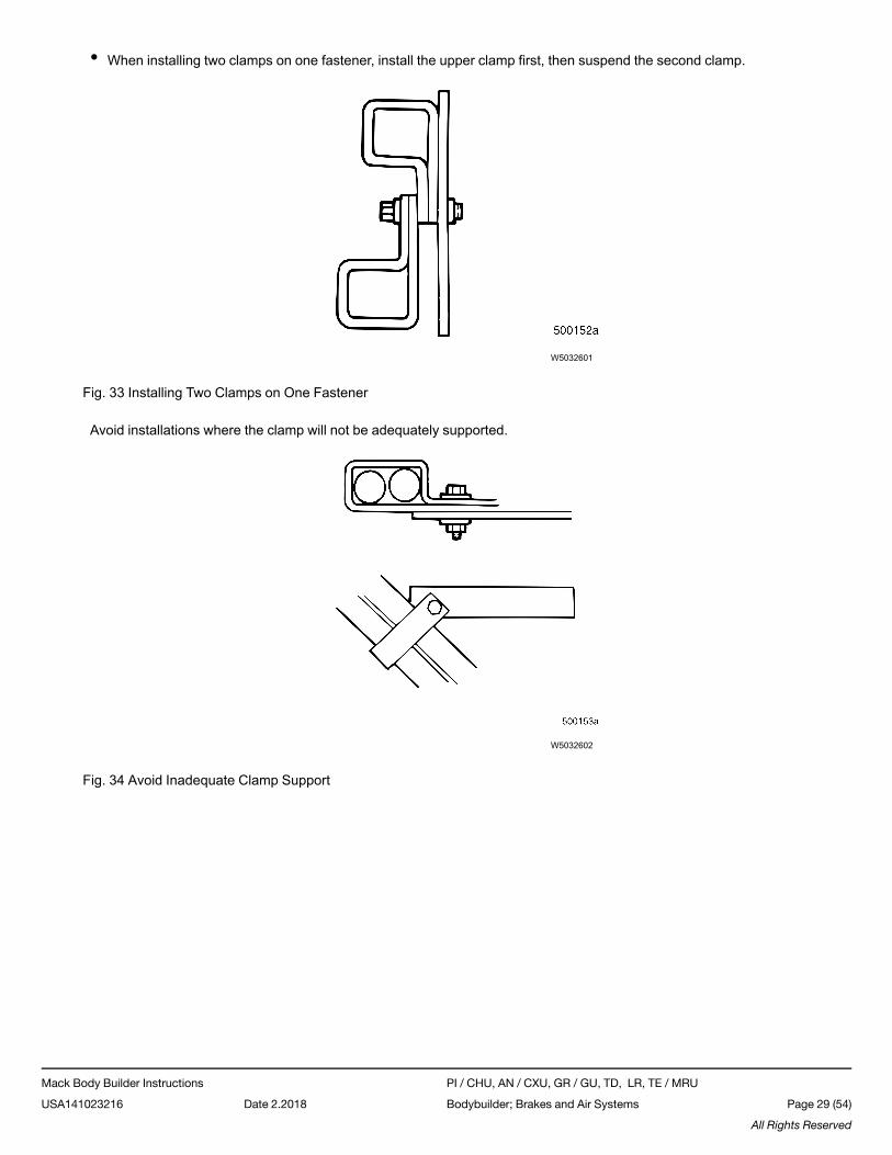
• When installing two clamps on one fastener, install the upper clamp first, then suspend the second clamp.
W5032601
Fig. 33 Installing Two Clamps on One Fastener
Avoid installations where the clamp will not be adequately supported.
W5032602
Fig. 34 Avoid Inadequate Clamp Support
Mack Body Builder Instructions PI / CHU, AN / CXU, GR / GU, TD, LR, TE / MRU
USA141023216 Date 2.2018 Bodybuilder; Brakes and Air Systems Page 29 (54)
All Rights Reserved
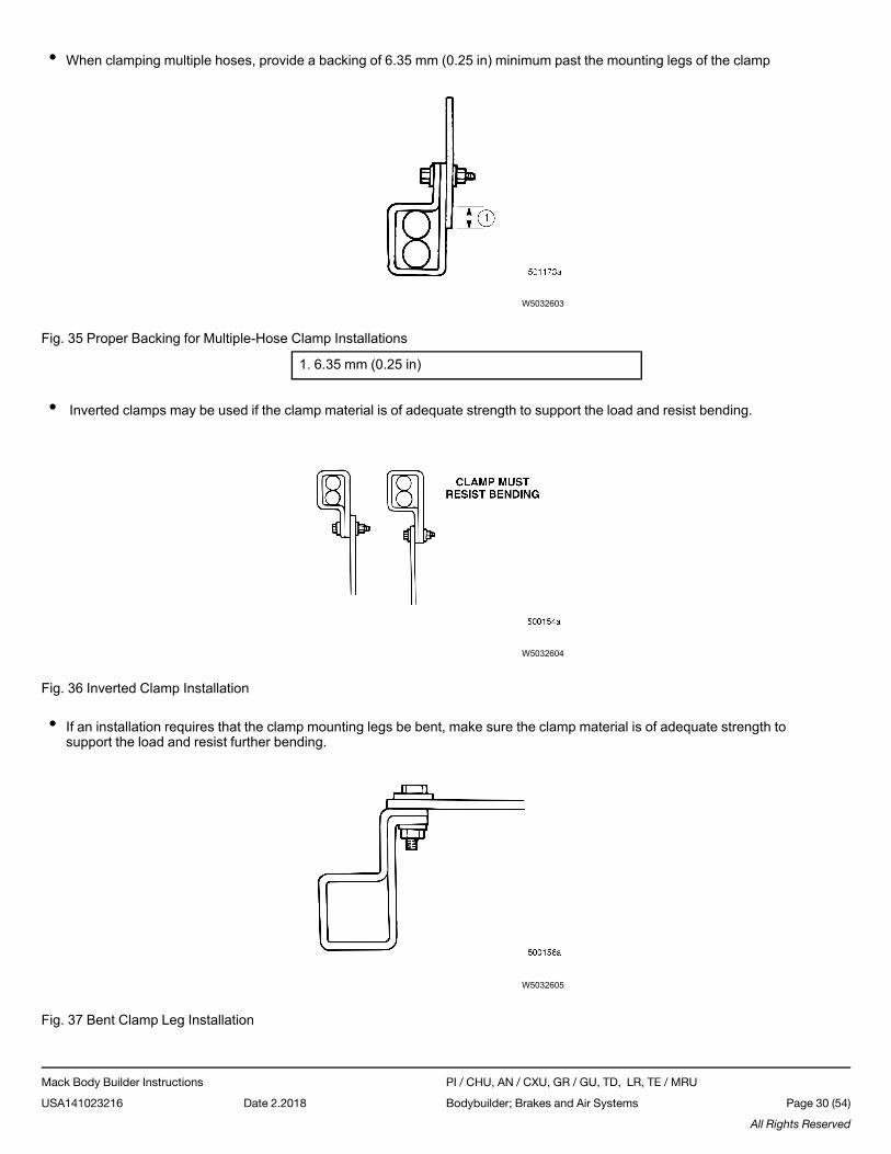
• When clamping multiple hoses, provide a backing of 6.35 mm (0.25 in) minimum past the mounting legs of the clamp
W5032603
Fig. 35 Proper Backing for Multiple-Hose Clamp Installations
1. 6.35 mm (0.25 in)
• Inverted clamps may be used if the clamp material is of adequate strength to support the load and resist bending.
W5032604
Fig. 36 Inverted Clamp Installation
• If an installation requires that the clamp mounting legs be bent, make sure the clamp material is of adequate strength tosupport the load and resist further bending.
W5032605
Fig. 37 Bent Clamp Leg Installation
Mack Body Builder Instructions PI / CHU, AN / CXU, GR / GU, TD, LR, TE / MRU
USA141023216 Date 2.2018 Bodybuilder; Brakes and Air Systems Page 30 (54)
All Rights Reserved
ClampsRubber-covered metal-band clamps of suitable size for the hose being clamped should be used for primary support. DONOT use a clamp that is too large for the diameter of the hose, because the hose may rub against the clamp and result in anair leak.
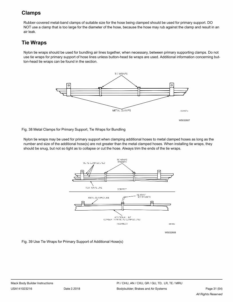
Tie WrapsNylon tie wraps should be used for bundling air lines together, when necessary, between primary supporting clamps. Do notuse tie wraps for primary support of hose lines unless button-head tie wraps are used. Additional information concerning but-ton-head tie wraps can be found in the section.
W5032607
Fig. 38 Metal Clamps for Primary Support, Tie Wraps for Bundling
Nylon tie wraps may be used for primary support when clamping additional hoses to metal clamped hoses as long as thenumber and size of the additional hose(s) are not greater than the metal clamped hoses. When installing tie wraps, theyshould be snug, but not so tight as to collapse or cut the hose. Always trim the ends of the tie wraps.
W5032608
Fig. 39 Use Tie Wraps for Primary Support of Additional Hose(s)
Mack Body Builder Instructions PI / CHU, AN / CXU, GR / GU, TD, LR, TE / MRU
USA141023216 Date 2.2018 Bodybuilder; Brakes and Air Systems Page 31 (54)
All Rights Reserved
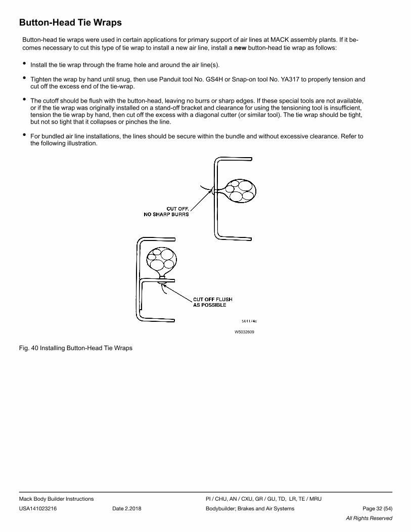
Button-Head Tie WrapsButton-head tie wraps were used in certain applications for primary support of air lines at MACK assembly plants. If it be-comes necessary to cut this type of tie wrap to install a new air line, install a new button-head tie wrap as follows:
• Install the tie wrap through the frame hole and around the air line(s).
• Tighten the wrap by hand until snug, then use Panduit tool No. GS4H or Snap-on tool No. YA317 to properly tension andcut off the excess end of the tie-wrap.
• The cutoff should be flush with the button-head, leaving no burrs or sharp edges. If these special tools are not available,or if the tie wrap was originally installed on a stand-off bracket and clearance for using the tensioning tool is insufficient,tension the tie wrap by hand, then cut off the excess with a diagonal cutter (or similar tool). The tie wrap should be tight,but not so tight that it collapses or pinches the line.
• For bundled air line installations, the lines should be secure within the bundle and without excessive clearance. Refer tothe following illustration.
W5032609
Fig. 40 Installing Button-Head Tie Wraps
Mack Body Builder Instructions PI / CHU, AN / CXU, GR / GU, TD, LR, TE / MRU
USA141023216 Date 2.2018 Bodybuilder; Brakes and Air Systems Page 32 (54)
All Rights Reserved
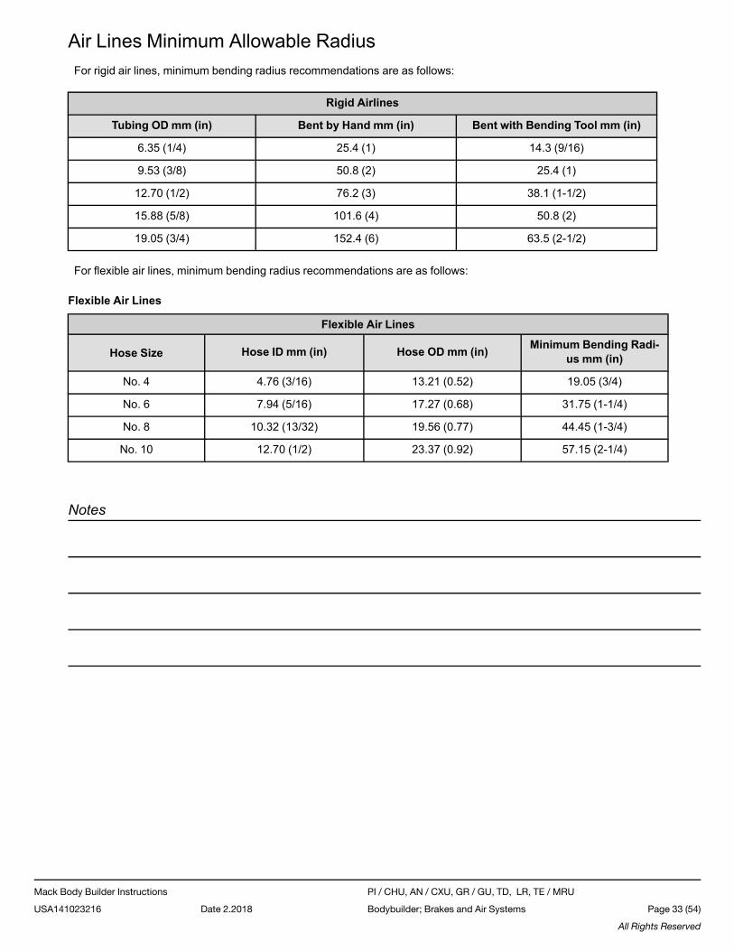
Air Lines Minimum Allowable RadiusFor rigid air lines, minimum bending radius recommendations are as follows:
Rigid Airlines
Tubing OD mm (in) Bent by Hand mm (in) Bent with Bending Tool mm (in)
6.35 (1/4) 25.4 (1) 14.3 (9/16)
9.53 (3/8) 50.8 (2) 25.4 (1)
12.70 (1/2) 76.2 (3) 38.1 (1-1/2)
15.88 (5/8) 101.6 (4) 50.8 (2)
19.05 (3/4) 152.4 (6) 63.5 (2-1/2)
For flexible air lines, minimum bending radius recommendations are as follows:
Flexible Air Lines
Flexible Air Lines
Hose Size Hose ID mm (in) Hose OD mm (in) Minimum Bending Radi-us mm (in)
No. 4 4.76 (3/16) 13.21 (0.52) 19.05 (3/4)
No. 6 7.94 (5/16) 17.27 (0.68) 31.75 (1-1/4)
No. 8 10.32 (13/32) 19.56 (0.77) 44.45 (1-3/4)
No. 10 12.70 (1/2) 23.37 (0.92) 57.15 (2-1/4)
Notes
Mack Body Builder Instructions PI / CHU, AN / CXU, GR / GU, TD, LR, TE / MRU
USA141023216 Date 2.2018 Bodybuilder; Brakes and Air Systems Page 33 (54)
All Rights Reserved
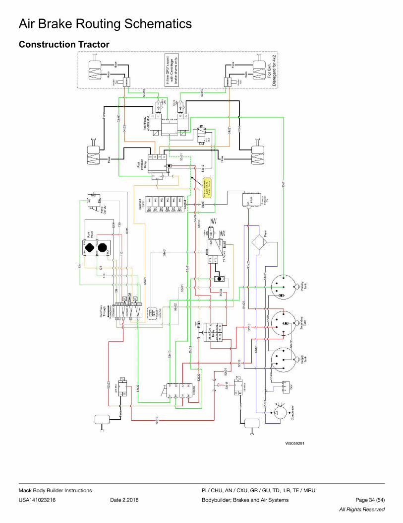
Air Brake Routing SchematicsConstruction Tractor
W5059291
Mack Body Builder Instructions PI / CHU, AN / CXU, GR / GU, TD, LR, TE / MRU
USA141023216 Date 2.2018 Bodybuilder; Brakes and Air Systems Page 34 (54)
All Rights Reserved
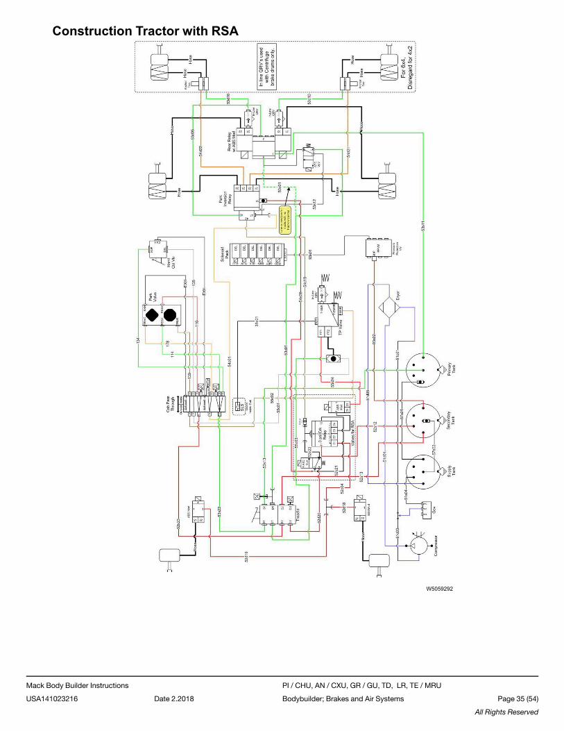
Construction Tractor with RSA
W5059292
Mack Body Builder Instructions PI / CHU, AN / CXU, GR / GU, TD, LR, TE / MRU
USA141023216 Date 2.2018 Bodybuilder; Brakes and Air Systems Page 35 (54)
All Rights Reserved
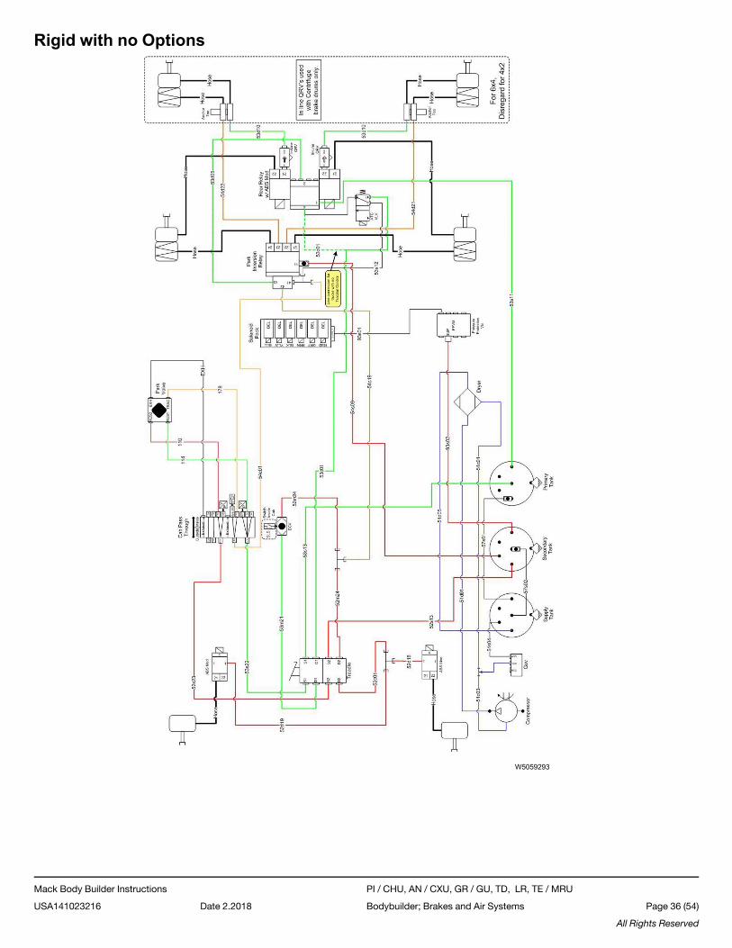
Rigid with no Options
W5059293
Mack Body Builder Instructions PI / CHU, AN / CXU, GR / GU, TD, LR, TE / MRU
USA141023216 Date 2.2018 Bodybuilder; Brakes and Air Systems Page 36 (54)
All Rights Reserved
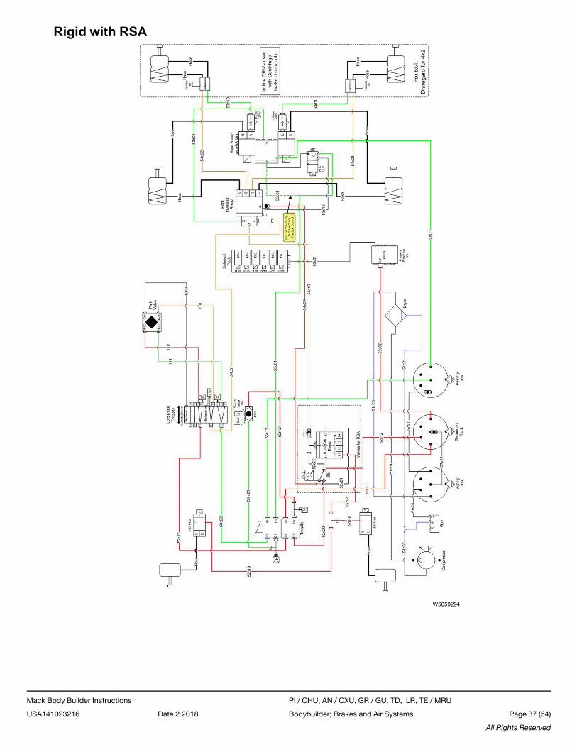
Rigid with RSA
W5059294
Mack Body Builder Instructions PI / CHU, AN / CXU, GR / GU, TD, LR, TE / MRU
USA141023216 Date 2.2018 Bodybuilder; Brakes and Air Systems Page 37 (54)
All Rights Reserved
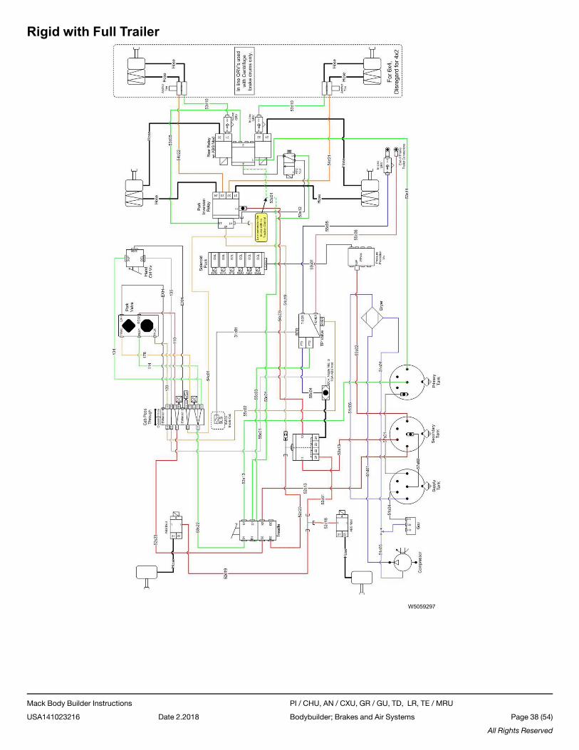
Rigid with Full Trailer
W5059297
Mack Body Builder Instructions PI / CHU, AN / CXU, GR / GU, TD, LR, TE / MRU
USA141023216 Date 2.2018 Bodybuilder; Brakes and Air Systems Page 38 (54)
All Rights Reserved
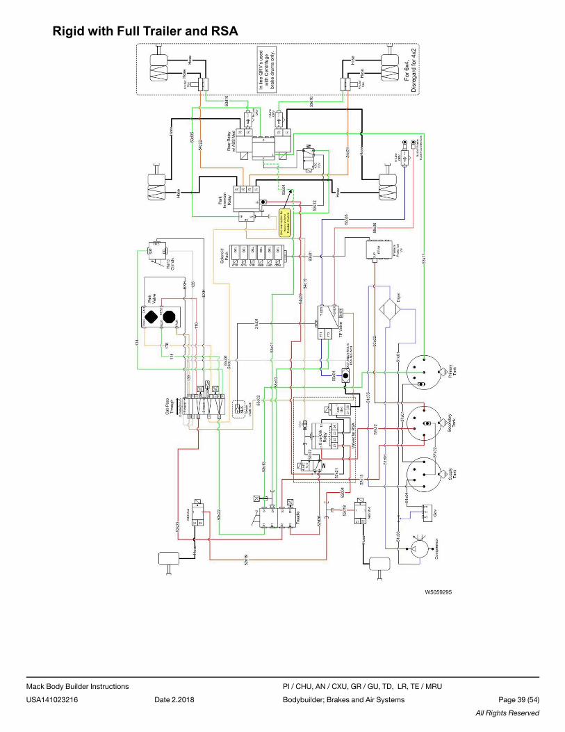
Rigid with Full Trailer and RSA
W5059295
Mack Body Builder Instructions PI / CHU, AN / CXU, GR / GU, TD, LR, TE / MRU
USA141023216 Date 2.2018 Bodybuilder; Brakes and Air Systems Page 39 (54)
All Rights Reserved
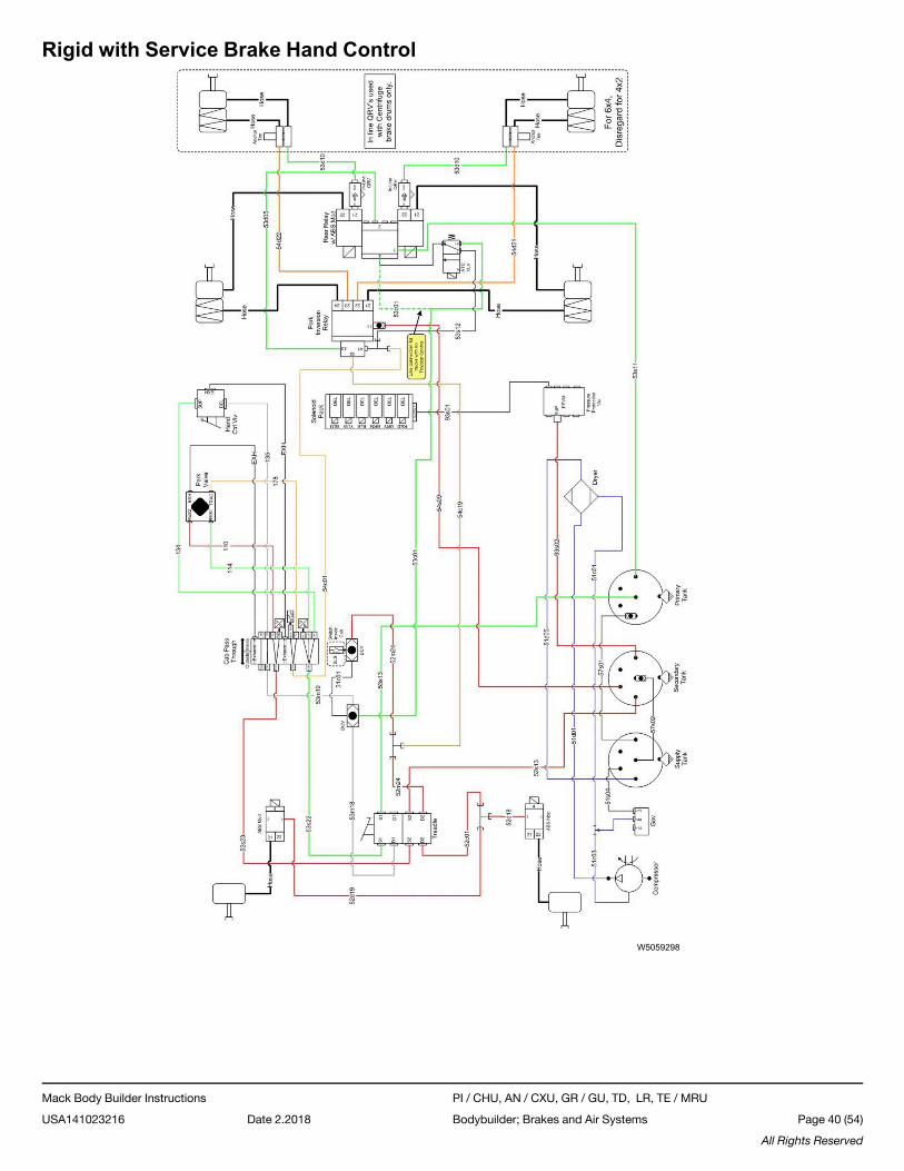
Rigid with Service Brake Hand Control
W5059298
Mack Body Builder Instructions PI / CHU, AN / CXU, GR / GU, TD, LR, TE / MRU
USA141023216 Date 2.2018 Bodybuilder; Brakes and Air Systems Page 40 (54)
All Rights Reserved
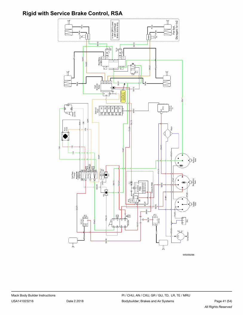
Rigid with Service Brake Control, RSA
W5059296
Mack Body Builder Instructions PI / CHU, AN / CXU, GR / GU, TD, LR, TE / MRU
USA141023216 Date 2.2018 Bodybuilder; Brakes and Air Systems Page 41 (54)
All Rights Reserved
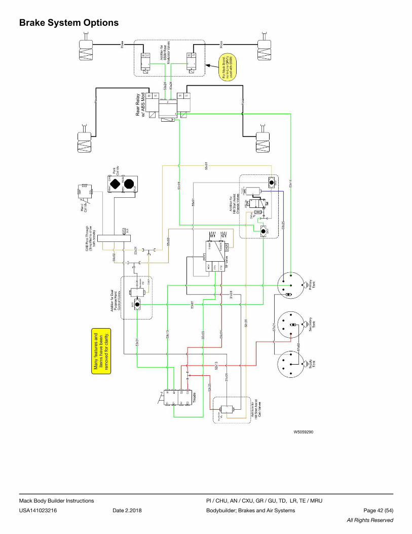
Brake System Options
W5059290
Mack Body Builder Instructions PI / CHU, AN / CXU, GR / GU, TD, LR, TE / MRU
USA141023216 Date 2.2018 Bodybuilder; Brakes and Air Systems Page 42 (54)
All Rights Reserved
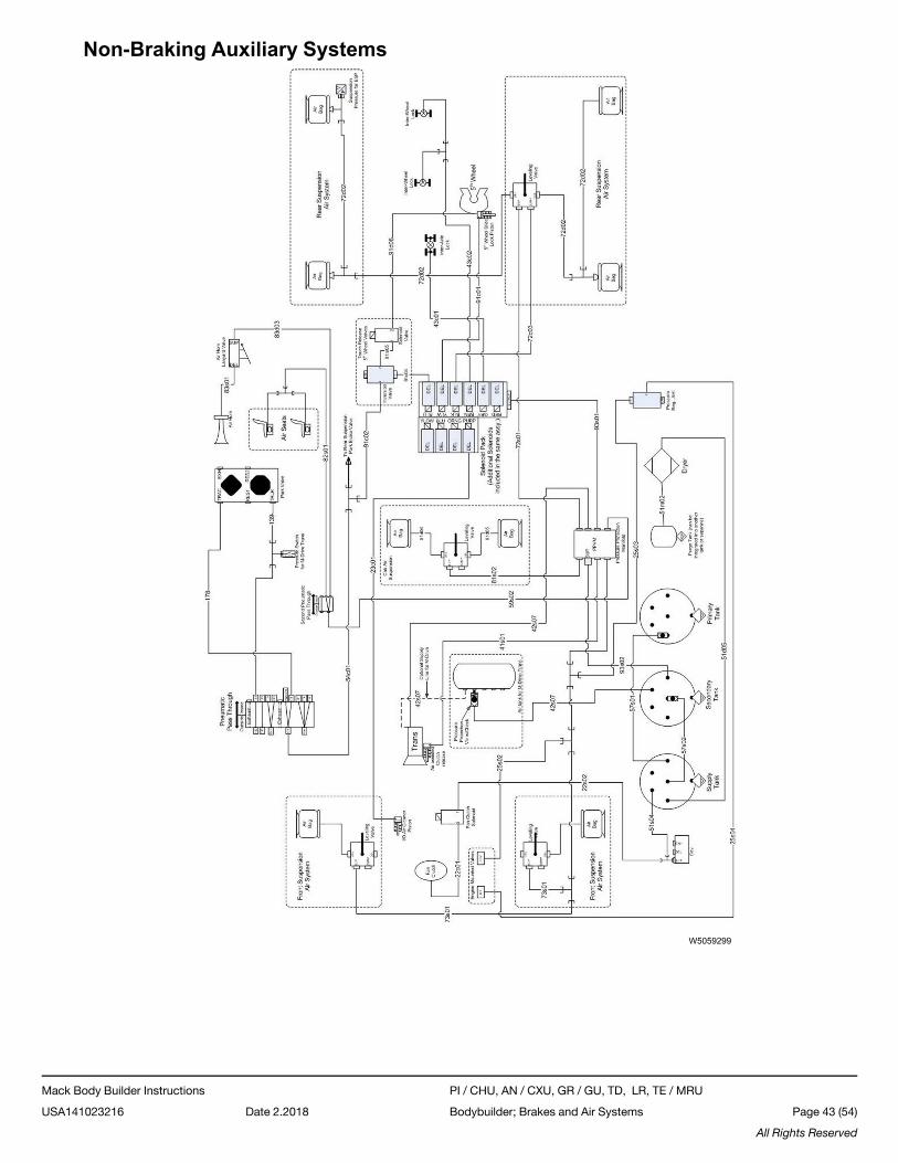
Non-Braking Auxiliary Systems
W5059299
Mack Body Builder Instructions PI / CHU, AN / CXU, GR / GU, TD, LR, TE / MRU
USA141023216 Date 2.2018 Bodybuilder; Brakes and Air Systems Page 43 (54)
All Rights Reserved
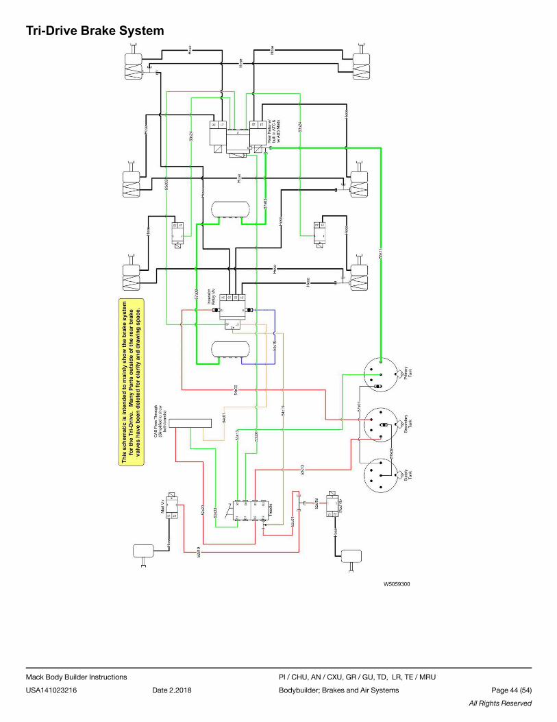
Tri-Drive Brake System
W5059300
Mack Body Builder Instructions PI / CHU, AN / CXU, GR / GU, TD, LR, TE / MRU
USA141023216 Date 2.2018 Bodybuilder; Brakes and Air Systems Page 44 (54)
All Rights Reserved
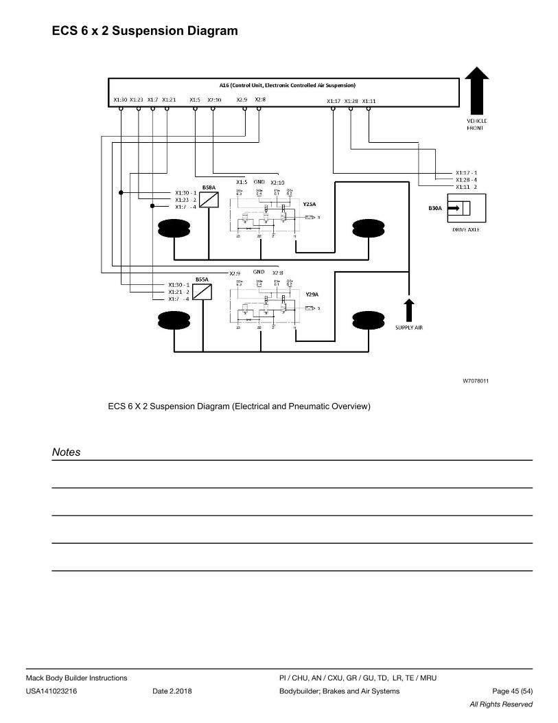
ECS 6 x 2 Suspension Diagram
W7078011
ECS 6 X 2 Suspension Diagram (Electrical and Pneumatic Overview)
Notes
Mack Body Builder Instructions PI / CHU, AN / CXU, GR / GU, TD, LR, TE / MRU
USA141023216 Date 2.2018 Bodybuilder; Brakes and Air Systems Page 45 (54)
All Rights Reserved
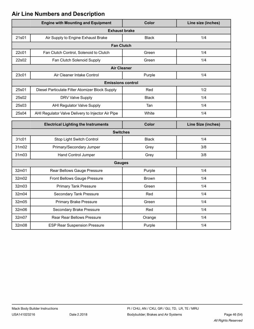
Air Line Numbers and DescriptionEngine with Mounting and Equipment Color Line size (inches)
Exhaust brake
21s01 Air Supply to Engine Exhaust Brake Black 1/4
Fan Clutch
22c01 Fan Clutch Control, Solenoid to Clutch Green 1/4
22s02 Fan Clutch Solenoid Supply Green 1/4
Air Cleaner
23c01 Air Cleaner Intake Control Purple 1/4
Emissions control
25s01 Diesel Particulate Filter Atomizer Block Supply Red 1/2
25s02 DRV Valve Supply Black 1/4
25s03 AHI Regulator Valve Supply Tan 1/4
25s04 AHI Regulator Valve Delivery to Injector Air Pipe White 1/4
Electrical Lighting the Instruments Color Line Size (inches)
Switches
31c01 Stop Light Switch Control Black 1/4
31m02 Primary/Secondary Jumper Grey 3/8
31m03 Hand Control Jumper Grey 3/8
Gauges
32m01 Rear Bellows Gauge Pressure Purple 1/4
32m02 Front Bellows Gauge Pressure Brown 1/4
32m03 Primary Tank Pressure Green 1/4
32m04 Secondary Tank Pressure Red 1/4
32m05 Primary Brake Pressure Green 1/4
32m06 Secondary Brake Pressure Red 1/4
32m07 Rear Rear Bellows Pressure Orange 1/4
32m08 ESP Rear Suspension Pressure Purple 1/4
Mack Body Builder Instructions PI / CHU, AN / CXU, GR / GU, TD, LR, TE / MRU
USA141023216 Date 2.2018 Bodybuilder; Brakes and Air Systems Page 46 (54)
All Rights Reserved
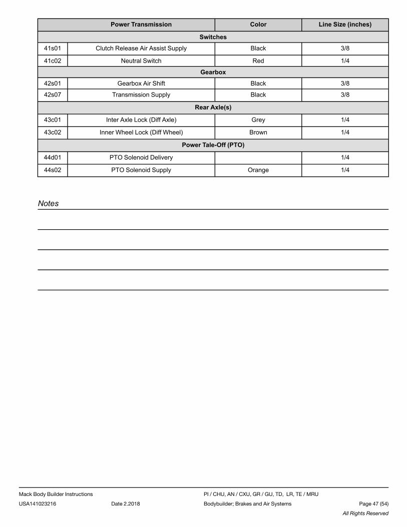
Power Transmission Color Line Size (inches)
Switches
41s01 Clutch Release Air Assist Supply Black 3/8
41c02 Neutral Switch Red 1/4
Gearbox
42s01 Gearbox Air Shift Black 3/8
42s07 Transmission Supply Black 3/8
Rear Axle(s)
43c01 Inter Axle Lock (Diff Axle) Grey 1/4
43c02 Inner Wheel Lock (Diff Wheel) Brown 1/4
Power Tale-Off (PTO)
44d01 PTO Solenoid Delivery 1/4
44s02 PTO Solenoid Supply Orange 1/4
Notes
Mack Body Builder Instructions PI / CHU, AN / CXU, GR / GU, TD, LR, TE / MRU
USA141023216 Date 2.2018 Bodybuilder; Brakes and Air Systems Page 47 (54)
All Rights Reserved
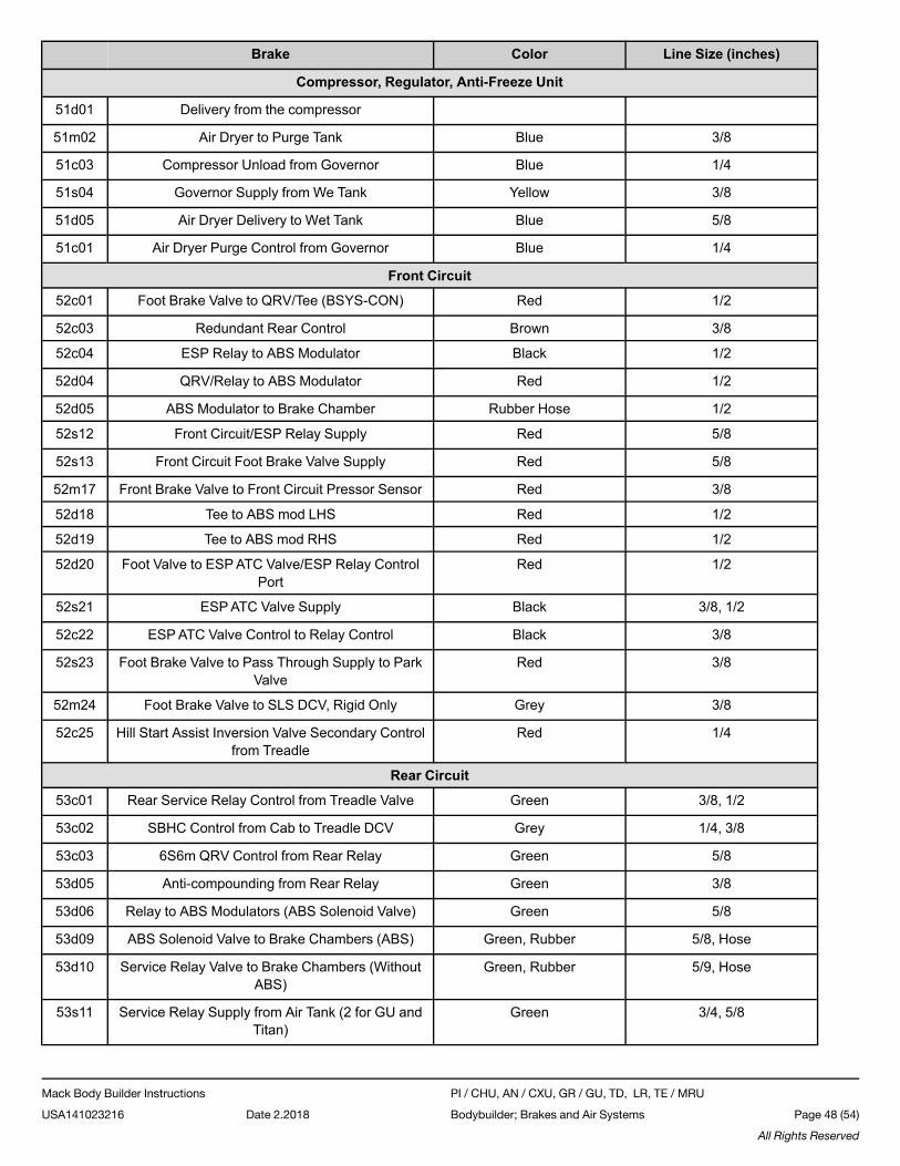
Brake Color Line Size (inches)
Compressor, Regulator, Anti-Freeze Unit
51d01 Delivery from the compressor
51m02 Air Dryer to Purge Tank Blue 3/8
51c03 Compressor Unload from Governor Blue 1/4
51s04 Governor Supply from We Tank Yellow 3/8
51d05 Air Dryer Delivery to Wet Tank Blue 5/8
51c01 Air Dryer Purge Control from Governor Blue 1/4
Front Circuit
52c01 Foot Brake Valve to QRV/Tee (BSYS-CON) Red 1/2
52c03 Redundant Rear Control Brown 3/8
52c04 ESP Relay to ABS Modulator Black 1/2
52d04 QRV/Relay to ABS Modulator Red 1/2
52d05 ABS Modulator to Brake Chamber Rubber Hose 1/2
52s12 Front Circuit/ESP Relay Supply Red 5/8
52s13 Front Circuit Foot Brake Valve Supply Red 5/8
52m17 Front Brake Valve to Front Circuit Pressor Sensor Red 3/8
52d18 Tee to ABS mod LHS Red 1/2
52d19 Tee to ABS mod RHS Red 1/2
52d20 Foot Valve to ESPATC Valve/ESP Relay ControlPort
Red 1/2
52s21 ESPATC Valve Supply Black 3/8, 1/2
52c22 ESPATC Valve Control to Relay Control Black 3/8
52s23 Foot Brake Valve to Pass Through Supply to ParkValve
Red 3/8
52m24 Foot Brake Valve to SLS DCV, Rigid Only Grey 3/8
52c25 Hill Start Assist Inversion Valve Secondary Controlfrom Treadle
Red 1/4
Rear Circuit
53c01 Rear Service Relay Control from Treadle Valve Green 3/8, 1/2
53c02 SBHC Control from Cab to Treadle DCV Grey 1/4, 3/8
53c03 6S6m QRV Control from Rear Relay Green 5/8
53d05 Anti-compounding from Rear Relay Green 3/8
53d06 Relay to ABS Modulators (ABS Solenoid Valve) Green 5/8
53d09 ABS Solenoid Valve to Brake Chambers (ABS) Green, Rubber 5/8, Hose
53d10 Service Relay Valve to Brake Chambers (WithoutABS)
Green, Rubber 5/9, Hose
53s11 Service Relay Supply from Air Tank (2 for GU andTitan)
Green 3/4, 5/8
Mack Body Builder Instructions PI / CHU, AN / CXU, GR / GU, TD, LR, TE / MRU
USA141023216 Date 2.2018 Bodybuilder; Brakes and Air Systems Page 48 (54)
All Rights Reserved
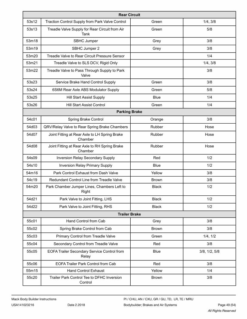
Rear Circuit
53s12 Traction Control Supply from Park Valve Control Green 1/4, 3/8
53s13 Treadle Valve Supply for Rear Circuit from AirTank
Green 5/8
53m18 SBHC Jumper Grey 3/8
53m19 SBHC Jumper 2 Grey 3/8
53m20 Treadle Valve to Rear Circuit Pressure Sensor 1/4
53m21 Treadle Valve to SLS DCV, Rigid Only 1/4, 3/8
53m22 Treadle Valve to Pass Through Supply to ParkValve
3/8
53s23 Service Brake Hand Control Supply Green 3/8
53s24 6S6M Rear Axle ABS Modulator Supply Green 5/8
53s25 Hill Start Assist Supply Blue 1/4
53s26 Hill Start Assist Control Green 1/4
Parking Brake
54c01 Spring Brake Control Orange 3/8
54d03 QRV/Relay Valve to Rear Spring Brake Chambers Rubber Hose
54d07 Joint Fitting at Rear Axle to LH Spring BrakeChamber
Rubber Hose
54d08 Joint Fitting at Rear Axle to RH Spring BrakeChamber
Rubber Hose
54s09 Inversion Relay Secondary Supply Red 1/2
54s10 Inversion Relay Primary Supply Blue 1/2
54m16 Park Control Exhaust from Dash Valve Yellow 3/8
54c19 Redundant Control Line from Treadle Valve Brown 3/8
54m20 Park Chamber Jumper Lines, Chambers Left toRight
Black 1/2
54d21 Park Valve to Joint Fitting, LHS Black 1/2
54d22 Park Valve to Joint Fitting, RHS Black 1/2
Trailer Brake
55c01 Hand Control from Cab Grey 3/8
55c02 Spring Brake Control from Cab Brown 3/8
55c03 Primary Control from Treadle Valve Green 1/4, 1/2
55c04 Secondary Control from Treadle Valve Red 3/8
55c05 EOFATrailer Secondary Service Control fromRelay
Blue 3/8, 1/2, 5/8
55c06 EOFATrailer Park Control from Cab Red 3/8
55m15 Hand Control Exhaust Yellow 1/4
55c20 Trailer Park Control Tee to DFHC InversionControl
Brown 3/8
Mack Body Builder Instructions PI / CHU, AN / CXU, GR / GU, TD, LR, TE / MRU
USA141023216 Date 2.2018 Bodybuilder; Brakes and Air Systems Page 49 (54)
All Rights Reserved
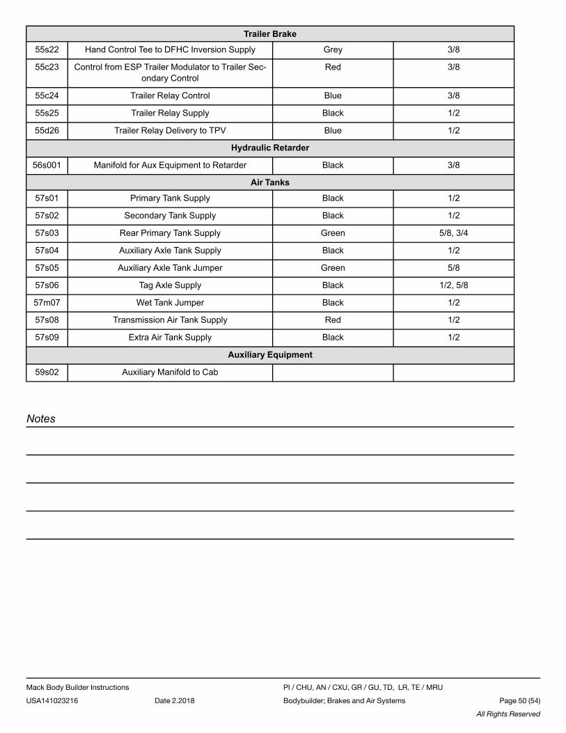
Trailer Brake
55s22 Hand Control Tee to DFHC Inversion Supply Grey 3/8
55c23 Control from ESP Trailer Modulator to Trailer Sec-ondary Control
Red 3/8
55c24 Trailer Relay Control Blue 3/8
55s25 Trailer Relay Supply Black 1/2
55d26 Trailer Relay Delivery to TPV Blue 1/2
Hydraulic Retarder
56s001 Manifold for Aux Equipment to Retarder Black 3/8
Air Tanks
57s01 Primary Tank Supply Black 1/2
57s02 Secondary Tank Supply Black 1/2
57s03 Rear Primary Tank Supply Green 5/8, 3/4
57s04 Auxiliary Axle Tank Supply Black 1/2
57s05 Auxiliary Axle Tank Jumper Green 5/8
57s06 Tag Axle Supply Black 1/2, 5/8
57m07 Wet Tank Jumper Black 1/2
57s08 Transmission Air Tank Supply Red 1/2
57s09 Extra Air Tank Supply Black 1/2
Auxiliary Equipment
59s02 Auxiliary Manifold to Cab
Notes
Mack Body Builder Instructions PI / CHU, AN / CXU, GR / GU, TD, LR, TE / MRU
USA141023216 Date 2.2018 Bodybuilder; Brakes and Air Systems Page 50 (54)
All Rights Reserved
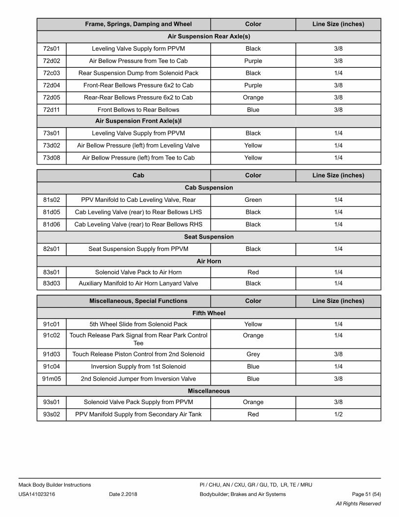
Frame, Springs, Damping and Wheel Color Line Size (inches)
Air Suspension Rear Axle(s)
72s01 Leveling Valve Supply form PPVM Black 3/8
72d02 Air Bellow Pressure from Tee to Cab Purple 3/8
72c03 Rear Suspension Dump from Solenoid Pack Black 1/4
72d04 Front-Rear Bellows Pressure 6x2 to Cab Purple 3/8
72d05 Rear-Rear Bellows Pressure 6x2 to Cab Orange 3/8
72d11 Front Bellows to Rear Bellows Blue 3/8
Air Suspension Front Axle(s)l
73s01 Leveling Valve Supply from PPVM Black 1/4
73d02 Air Bellow Pressure (left) from Leveling Valve Yellow 1/4
73d08 Air Bellow Pressure (left) from Tee to Cab Yellow 1/4
Cab Color Line Size (inches)
Cab Suspension
81s02 PPV Manifold to Cab Leveling Valve, Rear Green 1/4
81d05 Cab Leveling Valve (rear) to Rear Bellows LHS Black 1/4
81d06 Cab Leveling Valve (rear) to Rear Bellows RHS Black 1/4
Seat Suspension
82s01 Seat Suspension Supply from PPVM Black 1/4
Air Horn
83s01 Solenoid Valve Pack to Air Horn Red 1/4
83d03 Auxiliary Manifold to Air Horn Lanyard Valve Black 1/4
Miscellaneous, Special Functions Color Line Size (inches)
Fifth Wheel
91c01 5th Wheel Slide from Solenoid Pack Yellow 1/4
91c02 Touch Release Park Signal from Rear Park ControlTee
Orange 1/4
91d03 Touch Release Piston Control from 2nd Solenoid Grey 3/8
91c04 Inversion Supply from 1st Solenoid Blue 1/4
91m05 2nd Solenoid Jumper from Inversion Valve Blue 3/8
Miscellaneous
93s01 Solenoid Valve Pack Supply from PPVM Orange 3/8
93s02 PPV Manifold Supply from Secondary Air Tank Red 1/2
Mack Body Builder Instructions PI / CHU, AN / CXU, GR / GU, TD, LR, TE / MRU
USA141023216 Date 2.2018 Bodybuilder; Brakes and Air Systems Page 51 (54)
All Rights Reserved
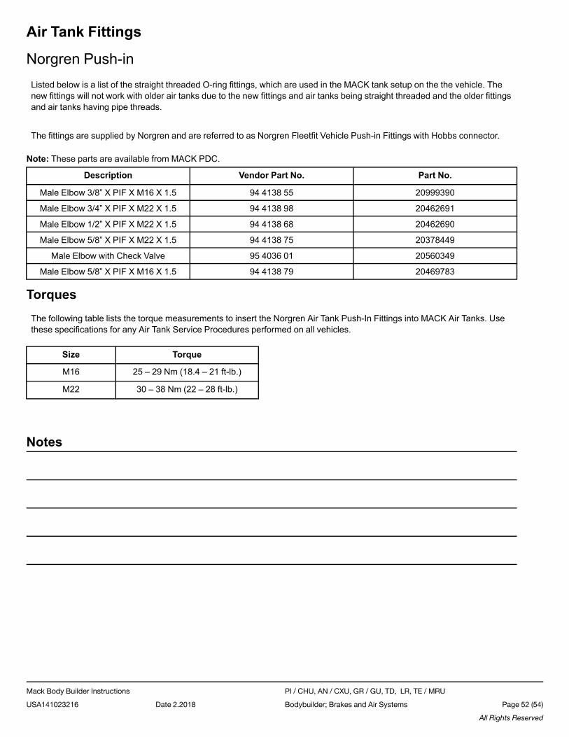
Air Tank Fittings
Norgren Push-inListed below is a list of the straight threaded O-ring fittings, which are used in the MACK tank setup on the the vehicle. Thenew fittings will not work with older air tanks due to the new fittings and air tanks being straight threaded and the older fittingsand air tanks having pipe threads.
The fittings are supplied by Norgren and are referred to as Norgren Fleetfit Vehicle Push-in Fittings with Hobbs connector.
Note: These parts are available from MACK PDC.
Description Vendor Part No. Part No.
Male Elbow 3/8” X PIF X M16 X 1.5 94 4138 55 20999390
Male Elbow 3/4” X PIF X M22 X 1.5 94 4138 98 20462691
Male Elbow 1/2” X PIF X M22 X 1.5 94 4138 68 20462690
Male Elbow 5/8” X PIF X M22 X 1.5 94 4138 75 20378449
Male Elbow with Check Valve 95 4036 01 20560349
Male Elbow 5/8” X PIF X M16 X 1.5 94 4138 79 20469783
TorquesThe following table lists the torque measurements to insert the Norgren Air Tank Push-In Fittings into MACK Air Tanks. Usethese specifications for any Air Tank Service Procedures performed on all vehicles.
Size Torque
M16 25 – 29 Nm (18.4 – 21 ft-lb.)
M22 30 – 38 Nm (22 – 28 ft-lb.)
Notes
Mack Body Builder Instructions PI / CHU, AN / CXU, GR / GU, TD, LR, TE / MRU
USA141023216 Date 2.2018 Bodybuilder; Brakes and Air Systems Page 52 (54)
All Rights Reserved
Brake LiteratureBendixCopies of service literature for Bendix components can now be accessed directly from the official internet site of the BendixCorporation.
To review and download Bendix service literature, please visit:
• http://www.bendix.com
EatonCopies of service literature for Eaton components can now be accessed directly from the official internet site of the EatonCorporation.
To review and download Eaton service literature, please visit:
• http://www.roadranger.com/rr/CustomerSupport/Support/LiteratureCenter/index.htm
GuniteCopies of service literature for Gunite components can now be accessed directly from the official internet site of the GuniteCorporation.
To review and download Gunite service literature, please visit:
• http://www.gunite.com/literature/
MeritorCopies of service literature for Meritor components can now be accessed directly from the official internet site of the ArvinMeritor Corporation.
To review and download Meritor service literature, please visit:
• https://www.meritor.com
NorgrenCopies of service literature for Norgren components can now be accessed directly from the official internet site of the Norg-ren Corporation.
To review and download Norgren service literature, please visit the following site:
• www.norgren.com/usa
Mack Body Builder Instructions PI / CHU, AN / CXU, GR / GU, TD, LR, TE / MRU
USA141023216 Date 2.2018 Bodybuilder; Brakes and Air Systems Page 53 (54)
All Rights Reserved
MGMCopies of service literature for MGM components can now be accessed directly from the official internet site of the IndianHead Industries.
To review and download MGM service literature, please visit the following site:
• http://mgmbrakes.com/
Chicago RawhideCopies of service literature for Chicago Rawhide components can now be accessed directly from the official internet site ofthe SKF corporation.
To review and download Chicago Rawhide service literature, please visit the following site:
• http://www.vsm.skf.com/usa/Heavyduty/index.html
Notes
Mack Body Builder Instructions PI / CHU, AN / CXU, GR / GU, TD, LR, TE / MRU
USA141023216 Date 2.2018 Bodybuilder; Brakes and Air Systems Page 54 (54)
All Rights Reserved