bmh servo motor
DESCRIPTION
Servo motoriTRANSCRIPT

BMHServo motorMotor manualV1.03, 11.2011
www.schneider-electric.com
0198
4411
1374
9, V
1.03
, 11.
2011
Important information
This manual is part of the product.
Carefully read this manual and observe all instructions.
Keep this manual for future reference.
Hand this manual and all other pertinent product documentation overto all users of the product.
Carefully read and observe all safety instructions and the chapter"Before you begin - safety information".
Some products are not available in all countries.For information on the availability of products, please consult the cata-log.
Subject to technical modifications without notice.
All details provided are technical data which do not constitute warran-ted qualities.
Most of the product designations are registered trademarks of theirrespective owners, even if this is not explicitly indicated.
Important information BMH
2 Servo motor
0198
4411
1374
9, V
1.03
, 11.
2011
Table of contents
Important information 2
Table of contents 3
About this manual 7
1 Introduction 9
1.1 Motor family 9
1.2 Options and accessories 10
1.3 Nameplate 11
1.4 Type code 12
2 Before you begin - safety information 13
2.1 Qualification of personnel 13
2.2 Intended use 13
2.3 Hazard categories 14
2.4 Basic information 15
2.5 Standards and terminology 17
3 Technical Data 19
3.1 General features 19
3.2 Motor-specific data 223.2.1 BMH070 223.2.2 BMH100 243.2.3 BMH140 263.2.4 BMH190 283.2.5 BMH205 29
3.3 Dimensions 31
3.4 Shaft-specific data 363.4.1 Force for pressing on 363.4.2 Shaft load 37
3.5 Options 393.5.1 Holding brake 393.5.2 Encoder 40
3.6 Conditions for UL 1004 41
3.7 Certifications 42
3.8 Declaration of conformity 43
4 Installation 45
BMH Table of contents
Servo motor 3
0198
4411
1374
9, V
1.03
, 11.
2011
4.1 Overview of procedure 47
4.2 Electromagnetic compatibility, EMC 47
4.3 Before mounting 49
4.4 Mounting the motor 544.4.1 Installation and connection of IP67 kit (accessory) 58
4.5 Electrical installation 604.5.1 Connectors and connector assignments 604.5.2 Power and encoder connection 644.5.3 Holding brake connection 70
5 Commissioning 71
6 Diagnostics and troubleshooting 73
6.1 Diagnostics and troubleshooting 736.1.1 Mechanical problems 736.1.2 Electrical problems 73
7 Accessories and spare parts 75
7.1 IP67 Kit 75
7.2 Connectors 75
7.3 Motor cables 767.3.1 Motor cables 1.5 mm2 767.3.2 Motor cables 2.5 mm2 777.3.3 Motor cables 4 mm2 787.3.4 Motor cables 6 mm2 797.3.5 Motor cables 10 mm2 80
7.4 Encoder cables 81
8 Service, maintenance and disposal 83
8.1 Service address 83
8.2 Storage 83
8.3 Maintenance 83
8.4 Changing the motor 85
8.5 Shipping, storage, disposal 85
9 Glossary 87
9.1 Units and conversion tables 879.1.1 Length 879.1.2 Mass 879.1.3 Force 879.1.4 Power 879.1.5 Rotation 889.1.6 Torque 889.1.7 Moment of inertia 889.1.8 Temperature 889.1.9 Conductor cross section 88
Table of contents BMH
4 Servo motor
0198
4411
1374
9, V
1.03
, 11.
2011
9.2 Terms and Abbreviations 89
10 Table of figures 91
11 Index 93
BMH Table of contents
Servo motor 5
0198
4411
1374
9, V
1.03
, 11.
2011
BMH
6 Servo motor
0198
4411
1374
9, V
1.03
, 11.
2011
About this manual
This manual is valid for BMH standard products. Chapter"1 Introduction" lists the type code for this product. The type codeallows you to identify whether your product is a standard product or acustomized version.
Source manuals The latest versions of the manuals can be downloaded from the Inter-net at:
http://www.schneider-electric.com
Corrections and suggestions We always try to further optimize our manuals. We welcome your sug-gestions and corrections.
Please get in touch with us by e-mail:[email protected].
Work steps If work steps must be performed consecutively, this sequence of stepsis represented as follows:
■ Special prerequisites for the following work steps▶ Step 1◁ Specific response to this work step▶ Step 2
If a response to a work step is indicated, this allows you to verify thatthe work step has been performed correctly.
Unless otherwise stated, the individual steps must be performed in thespecified sequence.
Making work easier Information on making work easier is highlighted by this symbol:
Sections highlighted this way provide supplementary information onmaking work easier.
SI units SI units are the original values. Converted units are shown in bracketsbehind the original value; they may be rounded.
Example:Minimum conductor cross section: 1.5 mm2 (AWG 14)
Glossary Explanations of special technical terms and abbreviations.
Index List of keywords with references to the corresponding page numbers.
BMH About this manual
Servo motor 7
0198
4411
1374
9, V
1.03
, 11.
2011
About this manual BMH
8 Servo motor
0198
4411
1374
9, V
1.03
, 11.
2011
1 Introduction
1
1.1 Motor family
The motors are AC synchronous servo motors with a very high powerdensity. A drive system consists of the AC synchronous servo motorand the appropriate drive. Maximum performance requires the motorand drive to be adapted to each other.
Features The AC synchronous servo motors excel with:
• High power density: The use of the latest magnetic materials andan optimized design result in motors with a shorter length at a com-parable torque.
• High peak torque: the peak torque can be up to four times the con-tinuous stall torque
BMH 1 Introduction
Servo motor 9
0198
4411
1374
9, V
1.03
, 11.
2011
1.2 Options and accessories
The motors are available with various options such as:
• Various encoder systems• Holding brake• Various shaft versions• Various degrees of protection• Various winding versions
The options can be found in the type code section on page 12.
For accessories see chapter "7 Accessories and spare parts", page75.
Gearboxes adapted to the motor can be found in the Lexium 32 prod-uct catalog.
1 Introduction BMH
10 Servo motor
0198
4411
1374
9, V
1.03
, 11.
2011
1.3 Nameplate
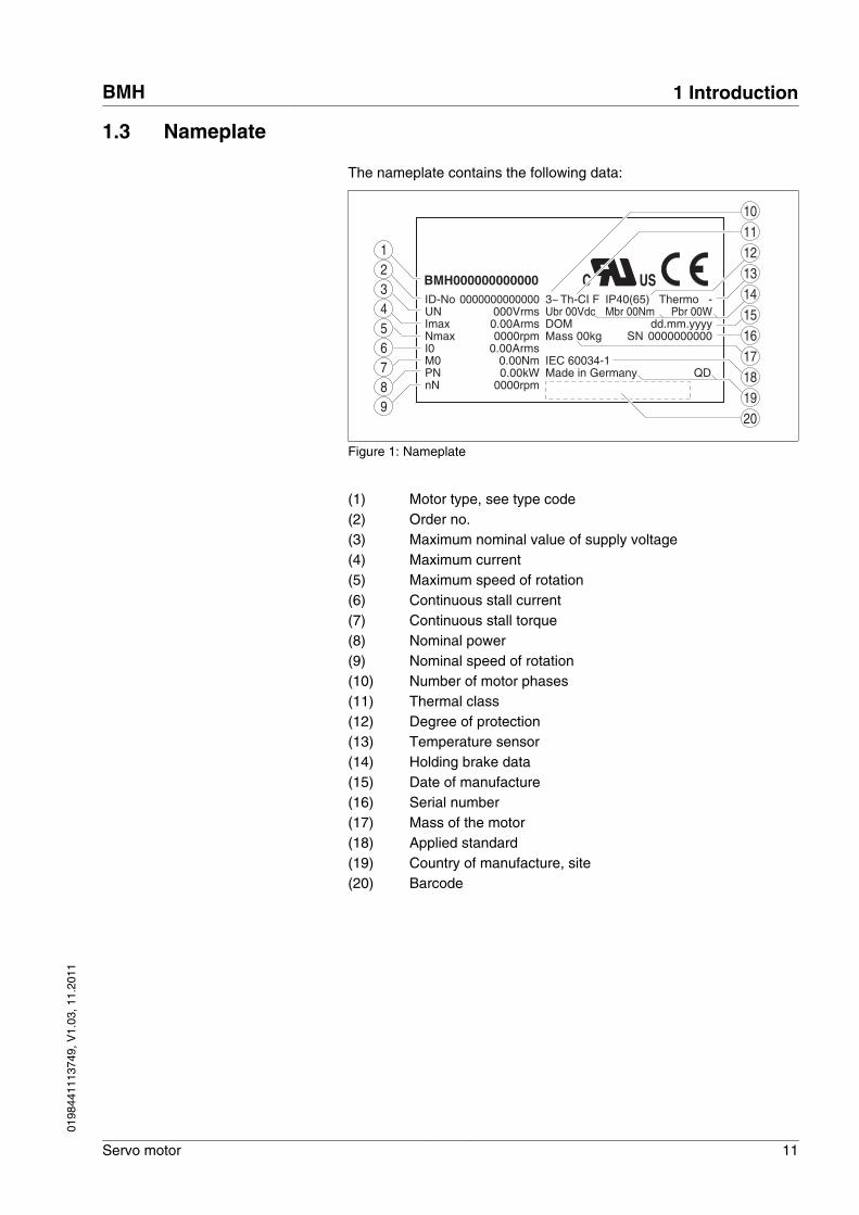
The nameplate contains the following data:
BMH000000000000ID-No
0.00Arms0.00Nm
0000rpm0.00Arms000Vrms
0000000000000
DOMSN
I0
UN
Nmax
USC
Imax
M0 Made in Germany
Ubr 00VdcTh-CI F
QD0.00kW0000rpm
PN nN
IEC 60034-1
3~
dd.mm.yyyy0000000000
IP40(65) Thermo -Mbr 00Nm Pbr 00W
21
5
78
6
9
11
15
1213143
4
19
161718
Mass 00kg
10
20
Figure 1: Nameplate
(1) Motor type, see type code(2) Order no.(3) Maximum nominal value of supply voltage(4) Maximum current(5) Maximum speed of rotation(6) Continuous stall current(7) Continuous stall torque(8) Nominal power(9) Nominal speed of rotation(10) Number of motor phases(11) Thermal class(12) Degree of protection(13) Temperature sensor(14) Holding brake data(15) Date of manufacture(16) Serial number(17) Mass of the motor(18) Applied standard(19) Country of manufacture, site(20) Barcode
BMH 1 Introduction
Servo motor 11
0198
4411
1374
9, V
1.03
, 11.
2011
1.4 Type code
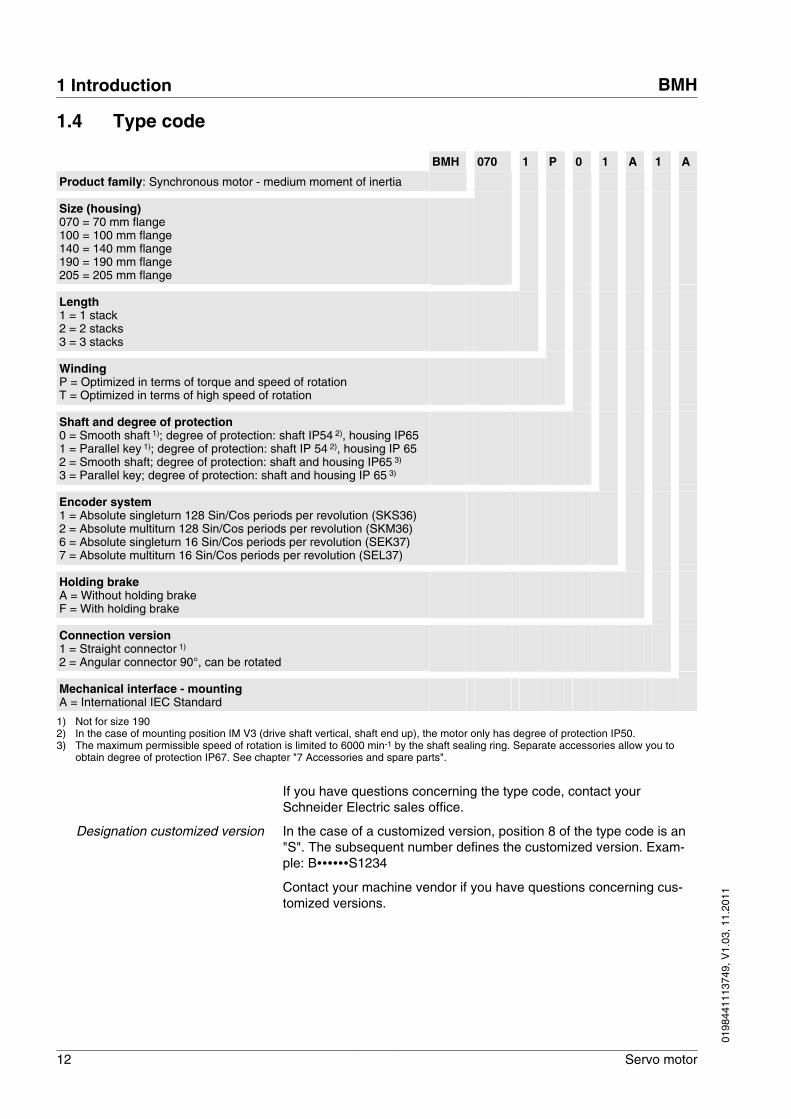
BMH 070 1 P 0 1 A 1 A
Product family: Synchronous motor - medium moment of inertia
Size (housing) 070 = 70 mm flange100 = 100 mm flange140 = 140 mm flange190 = 190 mm flange205 = 205 mm flange
Length 1 = 1 stack2 = 2 stacks3 = 3 stacks
Winding P = Optimized in terms of torque and speed of rotationT = Optimized in terms of high speed of rotation
Shaft and degree of protection 0 = Smooth shaft 1); degree of protection: shaft IP54 2), housing IP651 = Parallel key 1); degree of protection: shaft IP 54 2), housing IP 652 = Smooth shaft; degree of protection: shaft and housing IP65 3) 3 = Parallel key; degree of protection: shaft and housing IP 65 3)
Encoder system 1 = Absolute singleturn 128 Sin/Cos periods per revolution (SKS36)2 = Absolute multiturn 128 Sin/Cos periods per revolution (SKM36)6 = Absolute singleturn 16 Sin/Cos periods per revolution (SEK37)7 = Absolute multiturn 16 Sin/Cos periods per revolution (SEL37)
Holding brake A = Without holding brakeF = With holding brake
Connection version 1 = Straight connector 1) 2 = Angular connector 90°, can be rotated
Mechanical interface - mounting A = International IEC Standard
1) Not for size 1902) In the case of mounting position IM V3 (drive shaft vertical, shaft end up), the motor only has degree of protection IP50.3) The maximum permissible speed of rotation is limited to 6000 min-1 by the shaft sealing ring. Separate accessories allow you to
obtain degree of protection IP67. See chapter "7 Accessories and spare parts".
If you have questions concerning the type code, contact yourSchneider Electric sales office.
Designation customized version In the case of a customized version, position 8 of the type code is an"S". The subsequent number defines the customized version. Exam-ple: B∙∙∙∙∙∙S1234
Contact your machine vendor if you have questions concerning cus-tomized versions.
1 Introduction BMH
12 Servo motor
0198
4411
1374
9, V
1.03
, 11.
2011
2 Before you begin - safety information
2
2.1 Qualification of personnel
Only appropriately trained persons who are familiar with and under-stand the contents of this manual and all other pertinent product docu-mentation are authorized to work on and with this product. In addition,these persons must have received safety training to recognize andavoid hazards involved. These persons must have sufficient technicaltraining, knowledge and experience and be able to foresee and detectpotential hazards that may be caused by using the product, by chang-ing the settings and by the mechanical, electrical and electronic equip-ment of the entire system in which the product is used.
All persons working on and with the product must be fully familiar withall applicable standards, directives, and accident prevention regula-tions when performing such work.
2.2 Intended use
This product is a motor and intended for industrial use according tothis manual.
The product may only be used in compliance with all applicable safetyregulations and directives, the specified requirements and the techni-cal data.
Prior to using the product, you must perform a risk assessment in viewof the planned application. Based on the results, the appropriatesafety measures must be implemented.
Since the product is used as a component in an entire system, youmust ensure the safety of persons by means of the design of thisentire system (for example, machine design).
Operate the product only with the specified cables and accessories.Use only genuine accessories and spare parts.
The product must NEVER be operated in explosive atmospheres(hazardous locations, Ex areas).
Any use other than the use explicitly permitted is prohibited and canresult in hazards.
Electrical equipment should be installed, operated, serviced, andmaintained only by qualified personnel.
BMH 2 Before you begin - safety information
Servo motor 13
0198
4411
1374
9, V
1.03
, 11.
2011
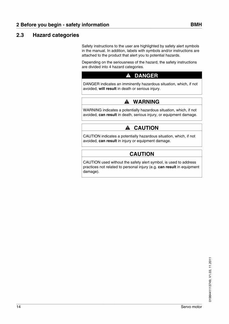
2.3 Hazard categories
Safety instructions to the user are highlighted by safety alert symbolsin the manual. In addition, labels with symbols and/or instructions areattached to the product that alert you to potential hazards.
Depending on the seriousness of the hazard, the safety instructionsare divided into 4 hazard categories.
DANGERDANGER indicates an imminently hazardous situation, which, if notavoided, will result in death or serious injury.
WARNINGWARNING indicates a potentially hazardous situation, which, if notavoided, can result in death, serious injury, or equipment damage.
CAUTIONCAUTION indicates a potentially hazardous situation, which, if notavoided, can result in injury or equipment damage.
CAUTIONCAUTION used without the safety alert symbol, is used to addresspractices not related to personal injury (e.g. can result in equipmentdamage).
2 Before you begin - safety information BMH
14 Servo motor
0198
4411
1374
9, V
1.03
, 11.
2011
2.4 Basic information
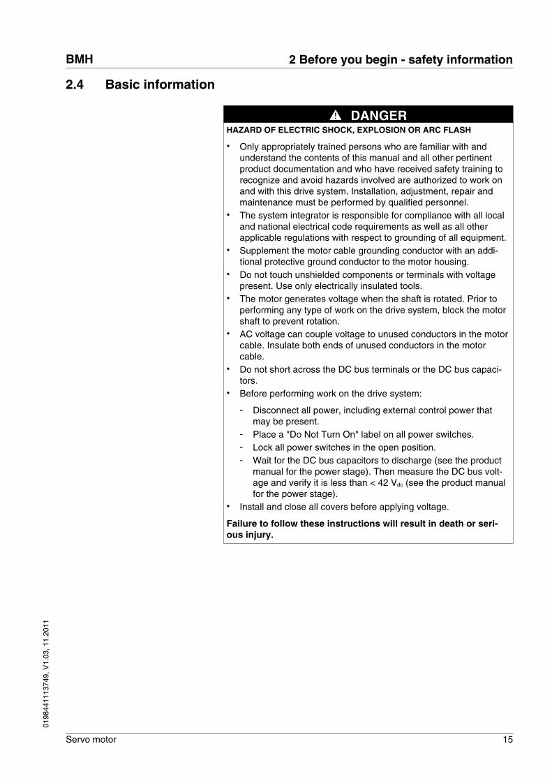
DANGERHAZARD OF ELECTRIC SHOCK, EXPLOSION OR ARC FLASH
• Only appropriately trained persons who are familiar with andunderstand the contents of this manual and all other pertinentproduct documentation and who have received safety training torecognize and avoid hazards involved are authorized to work onand with this drive system. Installation, adjustment, repair andmaintenance must be performed by qualified personnel.
• The system integrator is responsible for compliance with all localand national electrical code requirements as well as all otherapplicable regulations with respect to grounding of all equipment.
• Supplement the motor cable grounding conductor with an addi-tional protective ground conductor to the motor housing.
• Do not touch unshielded components or terminals with voltagepresent. Use only electrically insulated tools.
• The motor generates voltage when the shaft is rotated. Prior toperforming any type of work on the drive system, block the motorshaft to prevent rotation.
• AC voltage can couple voltage to unused conductors in the motorcable. Insulate both ends of unused conductors in the motorcable.
• Do not short across the DC bus terminals or the DC bus capaci-tors.
• Before performing work on the drive system:
- Disconnect all power, including external control power thatmay be present.
- Place a "Do Not Turn On" label on all power switches.- Lock all power switches in the open position.- Wait for the DC bus capacitors to discharge (see the product
manual for the power stage). Then measure the DC bus volt-age and verify it is less than < 42 Vdc (see the product manualfor the power stage).
• Install and close all covers before applying voltage.
Failure to follow these instructions will result in death or seri-ous injury.
BMH 2 Before you begin - safety information
Servo motor 15
0198
4411
1374
9, V
1.03
, 11.
2011
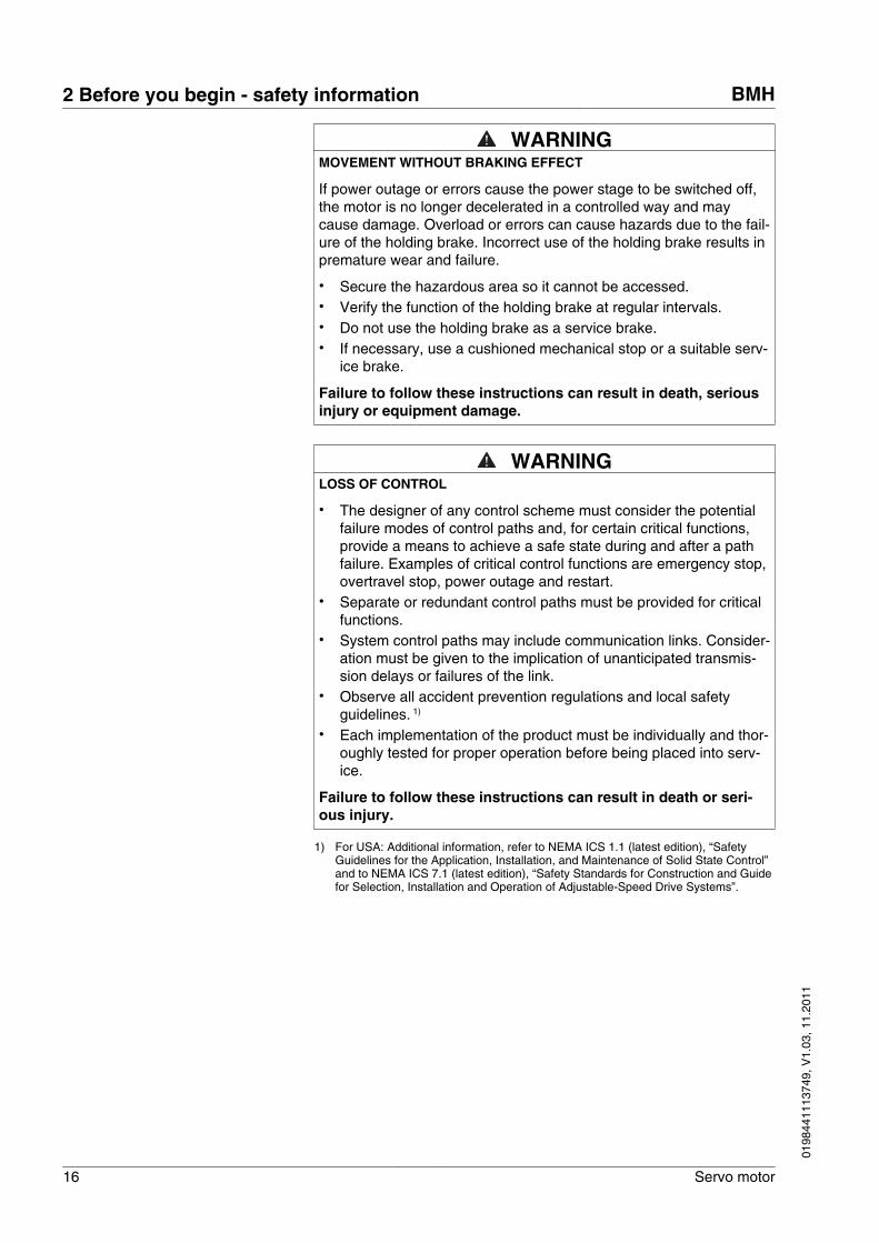
WARNINGMOVEMENT WITHOUT BRAKING EFFECT
If power outage or errors cause the power stage to be switched off,the motor is no longer decelerated in a controlled way and maycause damage. Overload or errors can cause hazards due to the fail-ure of the holding brake. Incorrect use of the holding brake results inpremature wear and failure.
• Secure the hazardous area so it cannot be accessed.• Verify the function of the holding brake at regular intervals.• Do not use the holding brake as a service brake.• If necessary, use a cushioned mechanical stop or a suitable serv-
ice brake.
Failure to follow these instructions can result in death, seriousinjury or equipment damage.
WARNINGLOSS OF CONTROL
• The designer of any control scheme must consider the potentialfailure modes of control paths and, for certain critical functions,provide a means to achieve a safe state during and after a pathfailure. Examples of critical control functions are emergency stop,overtravel stop, power outage and restart.
• Separate or redundant control paths must be provided for criticalfunctions.
• System control paths may include communication links. Consider-ation must be given to the implication of unanticipated transmis-sion delays or failures of the link.
• Observe all accident prevention regulations and local safetyguidelines. 1)
• Each implementation of the product must be individually and thor-oughly tested for proper operation before being placed into serv-ice.
Failure to follow these instructions can result in death or seri-ous injury.
1) For USA: Additional information, refer to NEMA ICS 1.1 (latest edition), “SafetyGuidelines for the Application, Installation, and Maintenance of Solid State Control”and to NEMA ICS 7.1 (latest edition), “Safety Standards for Construction and Guidefor Selection, Installation and Operation of Adjustable-Speed Drive Systems”.
2 Before you begin - safety information BMH
16 Servo motor
0198
4411
1374
9, V
1.03
, 11.
2011
2.5 Standards and terminology
Technical terms, terminology and the corresponding descriptions inthis manual are intended to use the terms or definitions of the perti-nent standards.
In the area of drive systems, this includes, but is not limited to, termssuch as "safety function", "safe state", "fault", "fault reset", "failure","error", "error message", "warning", "warning message", etc.
Among others, these standards include:
• IEC 61800 series: "Adjustable speed electrical power drive sys-tems"
• IEC 61158 series: "Industrial communication networks - Fieldbusspecifications"
• IEC 61784 series: "Industrial communication networks - Profiles"• IEC 61508 series: "Functional safety of electrical/electronic/
programmable electronic safety-related systems"
Also see the glossary at the end of this manual.
BMH 2 Before you begin - safety information
Servo motor 17
0198
4411
1374
9, V
1.03
, 11.
2011
2 Before you begin - safety information BMH
18 Servo motor
0198
4411
1374
9, V
1.03
, 11.
2011
3 Technical Data
3
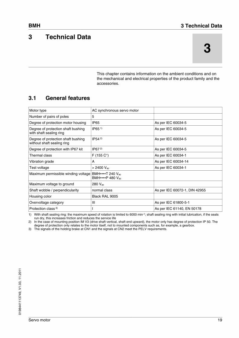
This chapter contains information on the ambient conditions and onthe mechanical and electrical properties of the product family and theaccessories.
3.1 General features
Motor type AC synchronous servo motor
Number of pairs of poles 5
Degree of protection motor housing IP65 As per IEC 60034-5
Degree of protection shaft bushingwith shaft sealing ring
IP65 1) As per IEC 60034-5
Degree of protection shaft bushingwithout shaft sealing ring
IP54 2) As per IEC 60034-5
Degree of protection with IP67 kit IP67 2) As per IEC 60034-5
Thermal class F (155 C°) As per IEC 60034-1
Vibration grade A As per IEC 60034-14
Test voltage > 2400 Vac As per IEC 60034-1
Maximum permissible winding voltage BMH∙∙∙∙T 240 Vac BMH∙∙∙∙P 480 Vac
Maximum voltage to ground 280 Vac
Shaft wobble / perpendicularity normal class As per IEC 60072-1, DIN 42955
Housing color Black RAL 9005
Overvoltage category III As per IEC 61800-5-1
Protection class 3) I As per IEC 61140, EN 50178
1) With shaft sealing ring: the maximum speed of rotation is limited to 6000 min-1; shaft sealing ring with initial lubrication, if the sealsrun dry, this increases friction and reduces the service life
2) In the case of mounting position IM V3 (drive shaft vertical, shaft end upward), the motor only has degree of protection IP 50. Thedegree of protection only relates to the motor itself, not to mounted components such as, for example, a gearbox.
3) The signals of the holding brake at CN1 and the signals at CN2 meet the PELV requirements.
BMH 3 Technical Data
Servo motor 19
0198
4411
1374
9, V
1.03
, 11.
2011
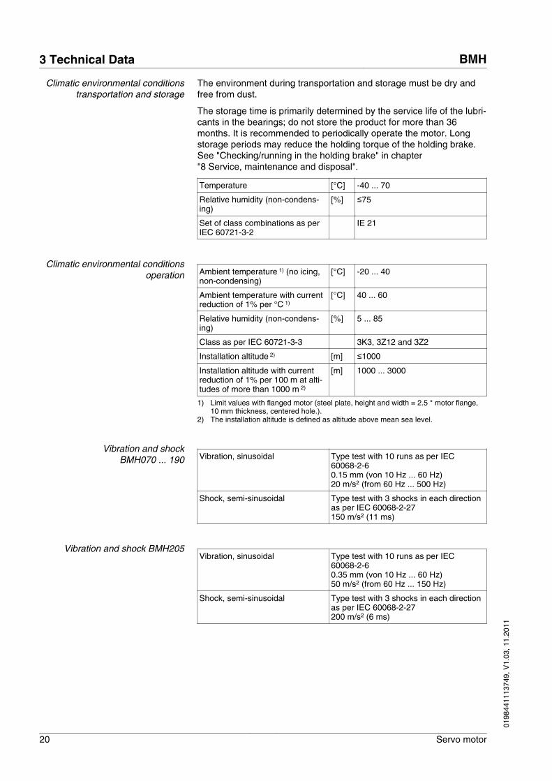
Climatic environmental conditionstransportation and storage
The environment during transportation and storage must be dry andfree from dust.
The storage time is primarily determined by the service life of the lubri-cants in the bearings; do not store the product for more than 36months. It is recommended to periodically operate the motor. Longstorage periods may reduce the holding torque of the holding brake.See "Checking/running in the holding brake" in chapter"8 Service, maintenance and disposal".
Temperature [°C] -40 ... 70
Relative humidity (non-condens-ing)
[%] ≤75
Set of class combinations as perIEC 60721-3-2
IE 21
Climatic environmental conditionsoperation Ambient temperature 1) (no icing,
non-condensing)[°C] -20 ... 40
Ambient temperature with currentreduction of 1% per °C 1)
[°C] 40 ... 60
Relative humidity (non-condens-ing)
[%] 5 ... 85
Class as per IEC 60721-3-3 3K3, 3Z12 and 3Z2
Installation altitude 2) [m] ≤1000
Installation altitude with currentreduction of 1% per 100 m at alti-tudes of more than 1000 m 2)
[m] 1000 ... 3000
1) Limit values with flanged motor (steel plate, height and width = 2.5 * motor flange,10 mm thickness, centered hole.).
2) The installation altitude is defined as altitude above mean sea level.
Vibration and shockBMH070 ... 190 Vibration, sinusoidal Type test with 10 runs as per IEC
60068-2-60.15 mm (von 10 Hz ... 60 Hz)20 m/s2 (from 60 Hz ... 500 Hz)
Shock, semi-sinusoidal Type test with 3 shocks in each directionas per IEC 60068-2-27150 m/s2 (11 ms)
Vibration and shock BMH205Vibration, sinusoidal Type test with 10 runs as per IEC
60068-2-60.35 mm (von 10 Hz ... 60 Hz)50 m/s2 (from 60 Hz ... 150 Hz)
Shock, semi-sinusoidal Type test with 3 shocks in each directionas per IEC 60068-2-27200 m/s2 (6 ms)
3 Technical Data BMH
20 Servo motor
0198
4411
1374
9, V
1.03
, 11.
2011
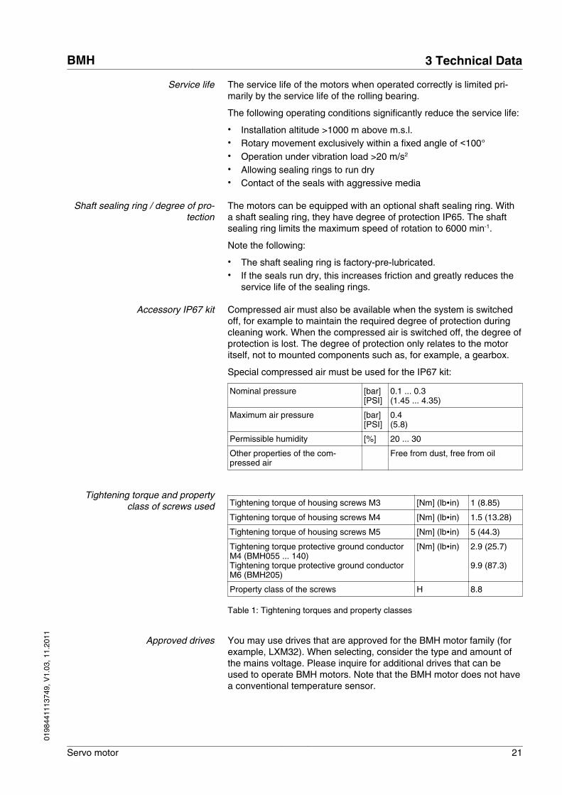
Service life The service life of the motors when operated correctly is limited pri-marily by the service life of the rolling bearing.
The following operating conditions significantly reduce the service life:
• Installation altitude >1000 m above m.s.l.• Rotary movement exclusively within a fixed angle of <100°• Operation under vibration load >20 m/s2
• Allowing sealing rings to run dry• Contact of the seals with aggressive media
Shaft sealing ring / degree of pro-tection
The motors can be equipped with an optional shaft sealing ring. Witha shaft sealing ring, they have degree of protection IP65. The shaftsealing ring limits the maximum speed of rotation to 6000 min-1.
Note the following:
• The shaft sealing ring is factory-pre-lubricated.• If the seals run dry, this increases friction and greatly reduces the
service life of the sealing rings.
Accessory IP67 kit Compressed air must also be available when the system is switchedoff, for example to maintain the required degree of protection duringcleaning work. When the compressed air is switched off, the degree ofprotection is lost. The degree of protection only relates to the motoritself, not to mounted components such as, for example, a gearbox.
Special compressed air must be used for the IP67 kit:
Nominal pressure [bar] [PSI]
0.1 ... 0.3(1.45 ... 4.35)
Maximum air pressure [bar] [PSI]
0.4(5.8)
Permissible humidity [%] 20 ... 30
Other properties of the com-pressed air
Free from dust, free from oil
Tightening torque and propertyclass of screws used Tightening torque of housing screws M3 [Nm] (lb∙in) 1 (8.85)
Tightening torque of housing screws M4 [Nm] (lb∙in) 1.5 (13.28)
Tightening torque of housing screws M5 [Nm] (lb∙in) 5 (44.3)
Tightening torque protective ground conductorM4 (BMH055 ... 140)Tightening torque protective ground conductorM6 (BMH205)
[Nm] (lb∙in) 2.9 (25.7)
9.9 (87.3)
Property class of the screws H 8.8
Table 1: Tightening torques and property classes
Approved drives You may use drives that are approved for the BMH motor family (forexample, LXM32). When selecting, consider the type and amount ofthe mains voltage. Please inquire for additional drives that can beused to operate BMH motors. Note that the BMH motor does not havea conventional temperature sensor.
BMH 3 Technical Data
Servo motor 21
0198
4411
1374
9, V
1.03
, 11.
2011
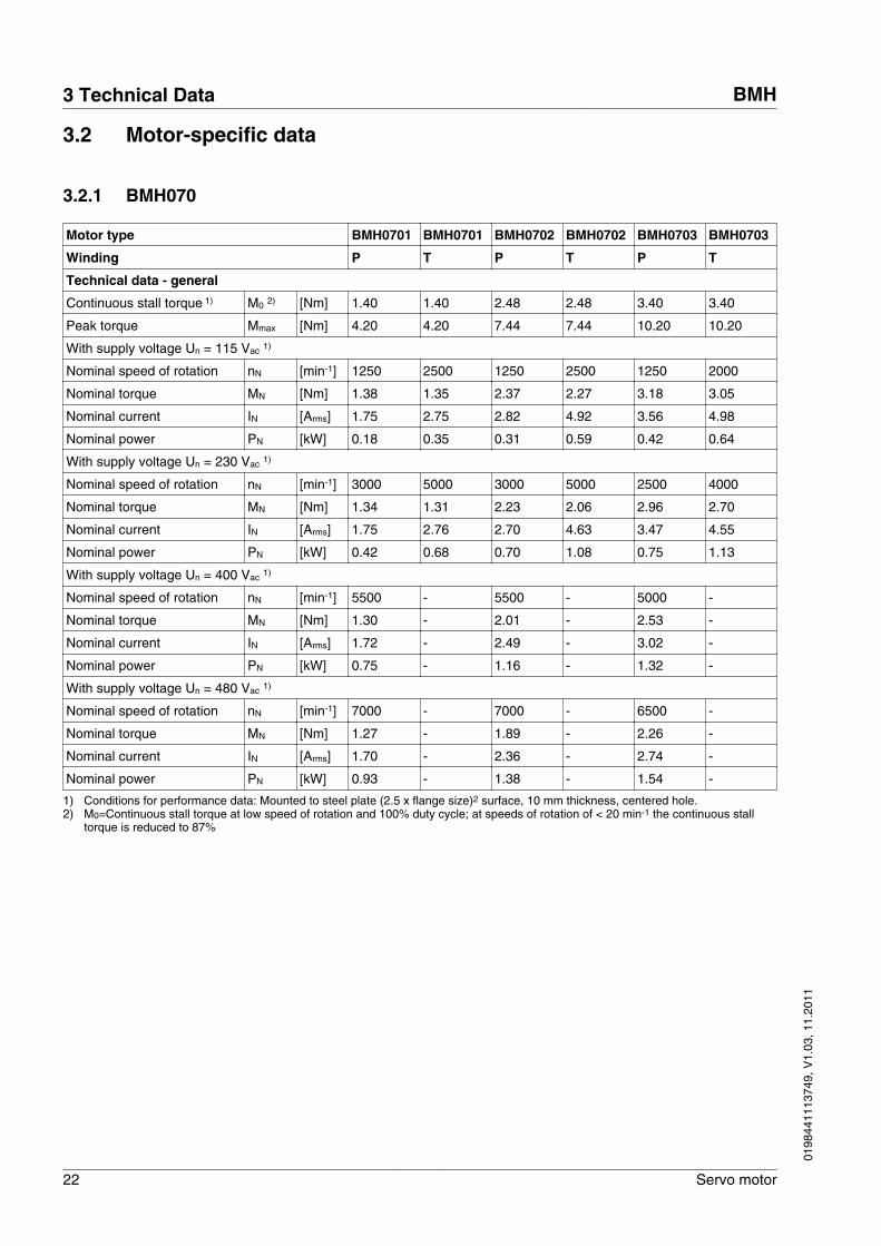
3.2 Motor-specific data
3.2.1 BMH070
Motor type BMH0701 BMH0701 BMH0702 BMH0702 BMH0703 BMH0703
Winding P T P T P T
Technical data - general
Continuous stall torque 1) M0 2) [Nm] 1.40 1.40 2.48 2.48 3.40 3.40
Peak torque Mmax [Nm] 4.20 4.20 7.44 7.44 10.20 10.20
With supply voltage Un = 115 Vac 1)
Nominal speed of rotation nN [min-1] 1250 2500 1250 2500 1250 2000
Nominal torque MN [Nm] 1.38 1.35 2.37 2.27 3.18 3.05
Nominal current IN [Arms] 1.75 2.75 2.82 4.92 3.56 4.98
Nominal power PN [kW] 0.18 0.35 0.31 0.59 0.42 0.64
With supply voltage Un = 230 Vac 1)
Nominal speed of rotation nN [min-1] 3000 5000 3000 5000 2500 4000
Nominal torque MN [Nm] 1.34 1.31 2.23 2.06 2.96 2.70
Nominal current IN [Arms] 1.75 2.76 2.70 4.63 3.47 4.55
Nominal power PN [kW] 0.42 0.68 0.70 1.08 0.75 1.13
With supply voltage Un = 400 Vac 1)
Nominal speed of rotation nN [min-1] 5500 - 5500 - 5000 -
Nominal torque MN [Nm] 1.30 - 2.01 - 2.53 -
Nominal current IN [Arms] 1.72 - 2.49 - 3.02 -
Nominal power PN [kW] 0.75 - 1.16 - 1.32 -
With supply voltage Un = 480 Vac 1)
Nominal speed of rotation nN [min-1] 7000 - 7000 - 6500 -
Nominal torque MN [Nm] 1.27 - 1.89 - 2.26 -
Nominal current IN [Arms] 1.70 - 2.36 - 2.74 -
Nominal power PN [kW] 0.93 - 1.38 - 1.54 -
1) Conditions for performance data: Mounted to steel plate (2.5 x flange size)2 surface, 10 mm thickness, centered hole.2) M0=Continuous stall torque at low speed of rotation and 100% duty cycle; at speeds of rotation of < 20 min-1 the continuous stall
torque is reduced to 87%
3 Technical Data BMH
22 Servo motor
0198
4411
1374
9, V
1.03
, 11.
2011
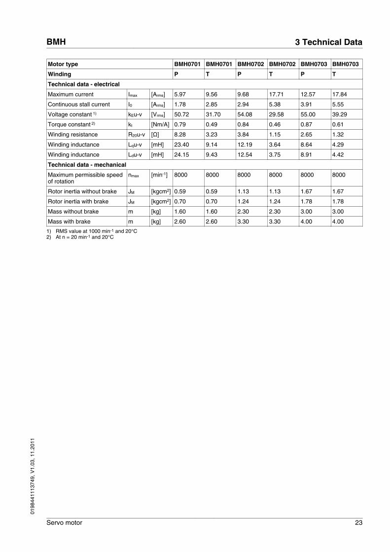
Motor type BMH0701 BMH0701 BMH0702 BMH0702 BMH0703 BMH0703
Winding P T P T P T
Technical data - electrical
Maximum current Imax [Arms] 5.97 9.56 9.68 17.71 12.57 17.84
Continuous stall current I0 [Arms] 1.78 2.85 2.94 5.38 3.91 5.55
Voltage constant 1) kEu-v [Vrms] 50.72 31.70 54.08 29.58 55.00 39.29
Torque constant 2) kt [Nm/A] 0.79 0.49 0.84 0.46 0.87 0.61
Winding resistance R20u-v [Ω] 8.28 3.23 3.84 1.15 2.65 1.32
Winding inductance Lqu-v [mH] 23.40 9.14 12.19 3.64 8.64 4.29
Winding inductance Ldu-v [mH] 24.15 9.43 12.54 3.75 8.91 4.42
Technical data - mechanical
Maximum permissible speedof rotation
nmax [min-1] 8000 8000 8000 8000 8000 8000
Rotor inertia without brake JM [kgcm2] 0.59 0.59 1.13 1.13 1.67 1.67
Rotor inertia with brake JM [kgcm2] 0.70 0.70 1.24 1.24 1.78 1.78
Mass without brake m [kg] 1.60 1.60 2.30 2.30 3.00 3.00
Mass with brake m [kg] 2.60 2.60 3.30 3.30 4.00 4.00
1) RMS value at 1000 min-1 and 20°C2) At n = 20 min-1 and 20°C
BMH 3 Technical Data
Servo motor 23
0198
4411
1374
9, V
1.03
, 11.
2011
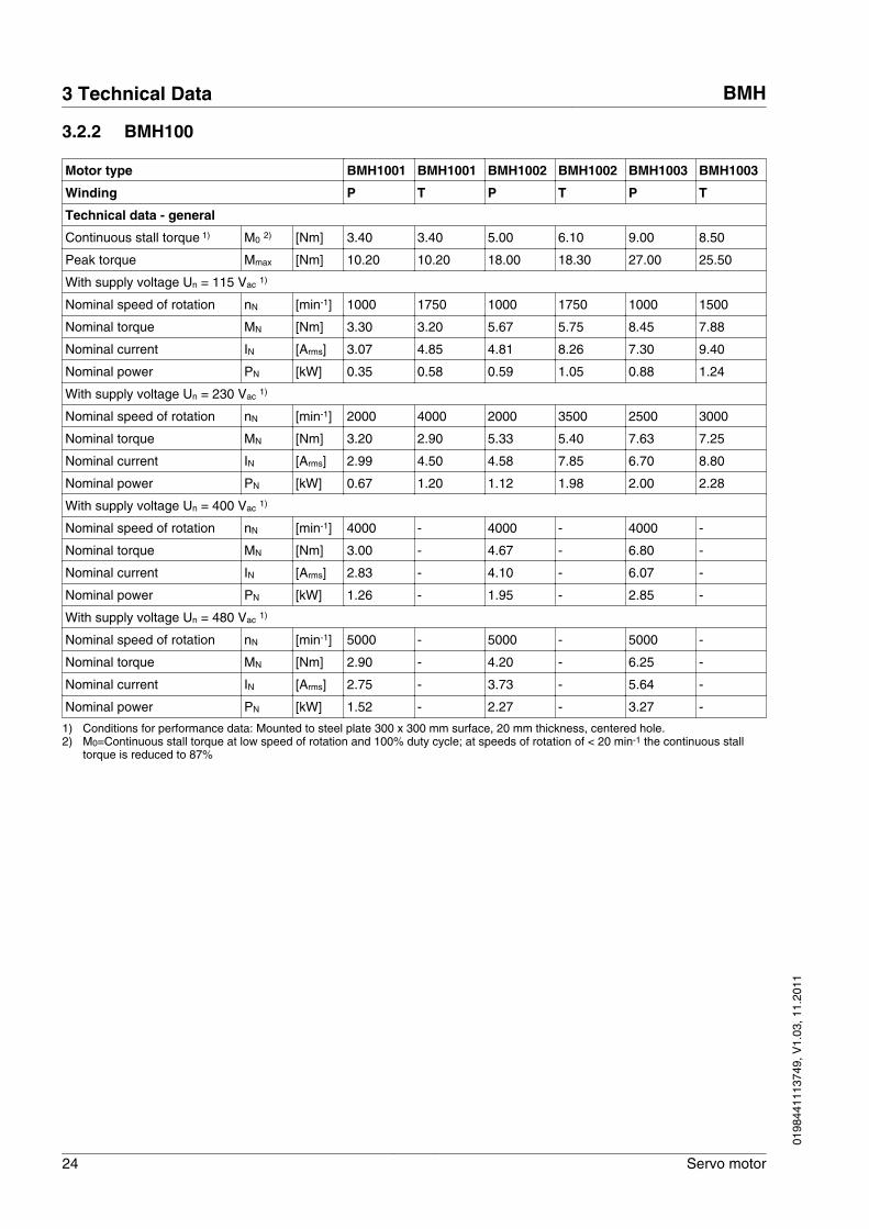
3.2.2 BMH100
Motor type BMH1001 BMH1001 BMH1002 BMH1002 BMH1003 BMH1003
Winding P T P T P T
Technical data - general
Continuous stall torque 1) M0 2) [Nm] 3.40 3.40 5.00 6.10 9.00 8.50
Peak torque Mmax [Nm] 10.20 10.20 18.00 18.30 27.00 25.50
With supply voltage Un = 115 Vac 1)
Nominal speed of rotation nN [min-1] 1000 1750 1000 1750 1000 1500
Nominal torque MN [Nm] 3.30 3.20 5.67 5.75 8.45 7.88
Nominal current IN [Arms] 3.07 4.85 4.81 8.26 7.30 9.40
Nominal power PN [kW] 0.35 0.58 0.59 1.05 0.88 1.24
With supply voltage Un = 230 Vac 1)
Nominal speed of rotation nN [min-1] 2000 4000 2000 3500 2500 3000
Nominal torque MN [Nm] 3.20 2.90 5.33 5.40 7.63 7.25
Nominal current IN [Arms] 2.99 4.50 4.58 7.85 6.70 8.80
Nominal power PN [kW] 0.67 1.20 1.12 1.98 2.00 2.28
With supply voltage Un = 400 Vac 1)
Nominal speed of rotation nN [min-1] 4000 - 4000 - 4000 -
Nominal torque MN [Nm] 3.00 - 4.67 - 6.80 -
Nominal current IN [Arms] 2.83 - 4.10 - 6.07 -
Nominal power PN [kW] 1.26 - 1.95 - 2.85 -
With supply voltage Un = 480 Vac 1)
Nominal speed of rotation nN [min-1] 5000 - 5000 - 5000 -
Nominal torque MN [Nm] 2.90 - 4.20 - 6.25 -
Nominal current IN [Arms] 2.75 - 3.73 - 5.64 -
Nominal power PN [kW] 1.52 - 2.27 - 3.27 -
1) Conditions for performance data: Mounted to steel plate 300 x 300 mm surface, 20 mm thickness, centered hole.2) M0=Continuous stall torque at low speed of rotation and 100% duty cycle; at speeds of rotation of < 20 min-1 the continuous stall
torque is reduced to 87%
3 Technical Data BMH
24 Servo motor
0198
4411
1374
9, V
1.03
, 11.
2011
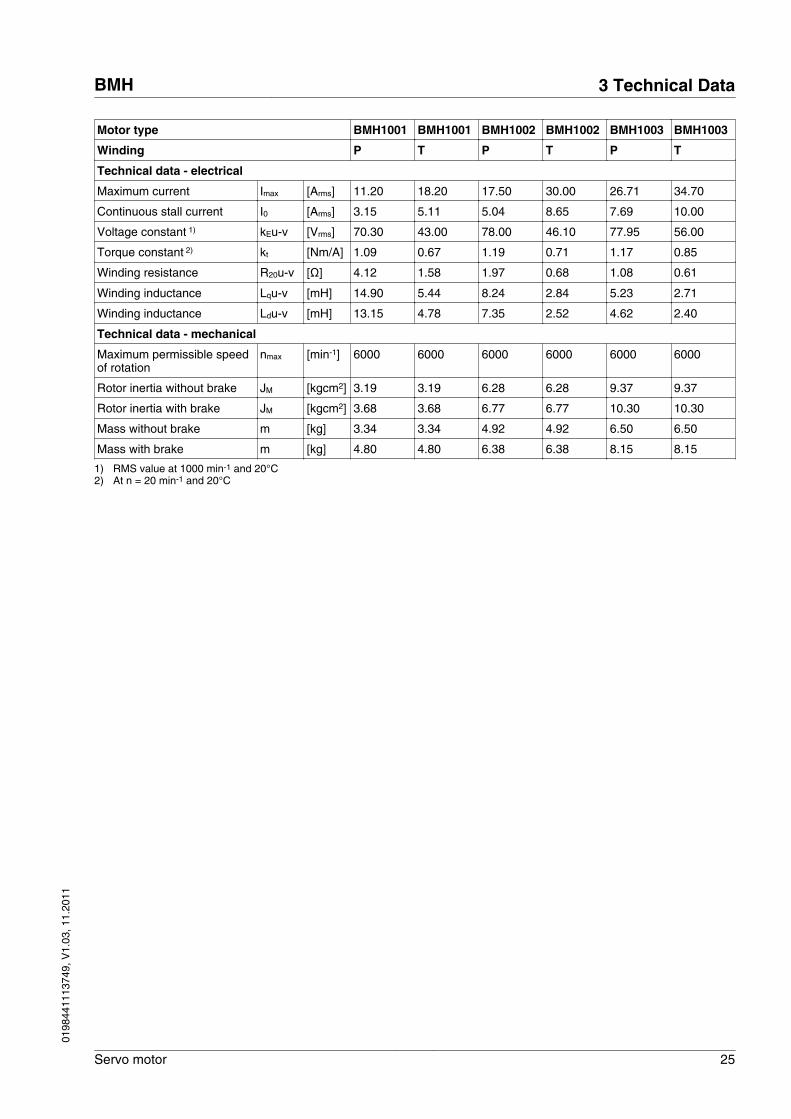
Motor type BMH1001 BMH1001 BMH1002 BMH1002 BMH1003 BMH1003
Winding P T P T P T
Technical data - electrical
Maximum current Imax [Arms] 11.20 18.20 17.50 30.00 26.71 34.70
Continuous stall current I0 [Arms] 3.15 5.11 5.04 8.65 7.69 10.00
Voltage constant 1) kEu-v [Vrms] 70.30 43.00 78.00 46.10 77.95 56.00
Torque constant 2) kt [Nm/A] 1.09 0.67 1.19 0.71 1.17 0.85
Winding resistance R20u-v [Ω] 4.12 1.58 1.97 0.68 1.08 0.61
Winding inductance Lqu-v [mH] 14.90 5.44 8.24 2.84 5.23 2.71
Winding inductance Ldu-v [mH] 13.15 4.78 7.35 2.52 4.62 2.40
Technical data - mechanical
Maximum permissible speedof rotation
nmax [min-1] 6000 6000 6000 6000 6000 6000
Rotor inertia without brake JM [kgcm2] 3.19 3.19 6.28 6.28 9.37 9.37
Rotor inertia with brake JM [kgcm2] 3.68 3.68 6.77 6.77 10.30 10.30
Mass without brake m [kg] 3.34 3.34 4.92 4.92 6.50 6.50
Mass with brake m [kg] 4.80 4.80 6.38 6.38 8.15 8.15
1) RMS value at 1000 min-1 and 20°C2) At n = 20 min-1 and 20°C
BMH 3 Technical Data
Servo motor 25
0198
4411
1374
9, V
1.03
, 11.
2011
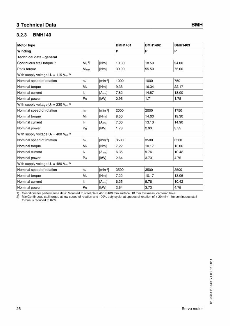
3.2.3 BMH140
Motor type BMH1401 BMH1402 BMH1403
Winding P P P
Technical data - general
Continuous stall torque 1) M0 2) [Nm] 10.30 18.50 24.00
Peak torque Mmax [Nm] 39.90 55.50 75.00
With supply voltage Un = 115 Vac 1)
Nominal speed of rotation nN [min-1] 1000 1000 750
Nominal torque MN [Nm] 9.36 16.34 22.17
Nominal current IN [Arms] 7.82 14.87 18.00
Nominal power PN [kW] 0.98 1.71 1.78
With supply voltage Un = 230 Vac 1)
Nominal speed of rotation nN [min-1] 2000 2000 1750
Nominal torque MN [Nm] 8.50 14.00 19.30
Nominal current IN [Arms] 7.30 13.13 14.90
Nominal power PN [kW] 1.78 2.93 3.55
With supply voltage Un = 400 Vac 1)
Nominal speed of rotation nN [min-1] 3500 3500 3500
Nominal torque MN [Nm] 7.22 10.17 13.06
Nominal current IN [Arms] 6.35 9.76 10.42
Nominal power PN [kW] 2.64 3.73 4.75
With supply voltage Un = 480 Vac 1)
Nominal speed of rotation nN [min-1] 3500 3500 3500
Nominal torque MN [Nm] 7.22 10.17 13.06
Nominal current IN [Arms] 6.35 9.76 10.42
Nominal power PN [kW] 2.64 3.73 4.75
1) Conditions for performance data: Mounted to steel plate 400 x 400 mm surface, 10 mm thickness, centered hole.2) M0=Continuous stall torque at low speed of rotation and 100% duty cycle; at speeds of rotation of < 20 min-1 the continuous stall
torque is reduced to 87%
3 Technical Data BMH
26 Servo motor
0198
4411
1374
9, V
1.03
, 11.
2011
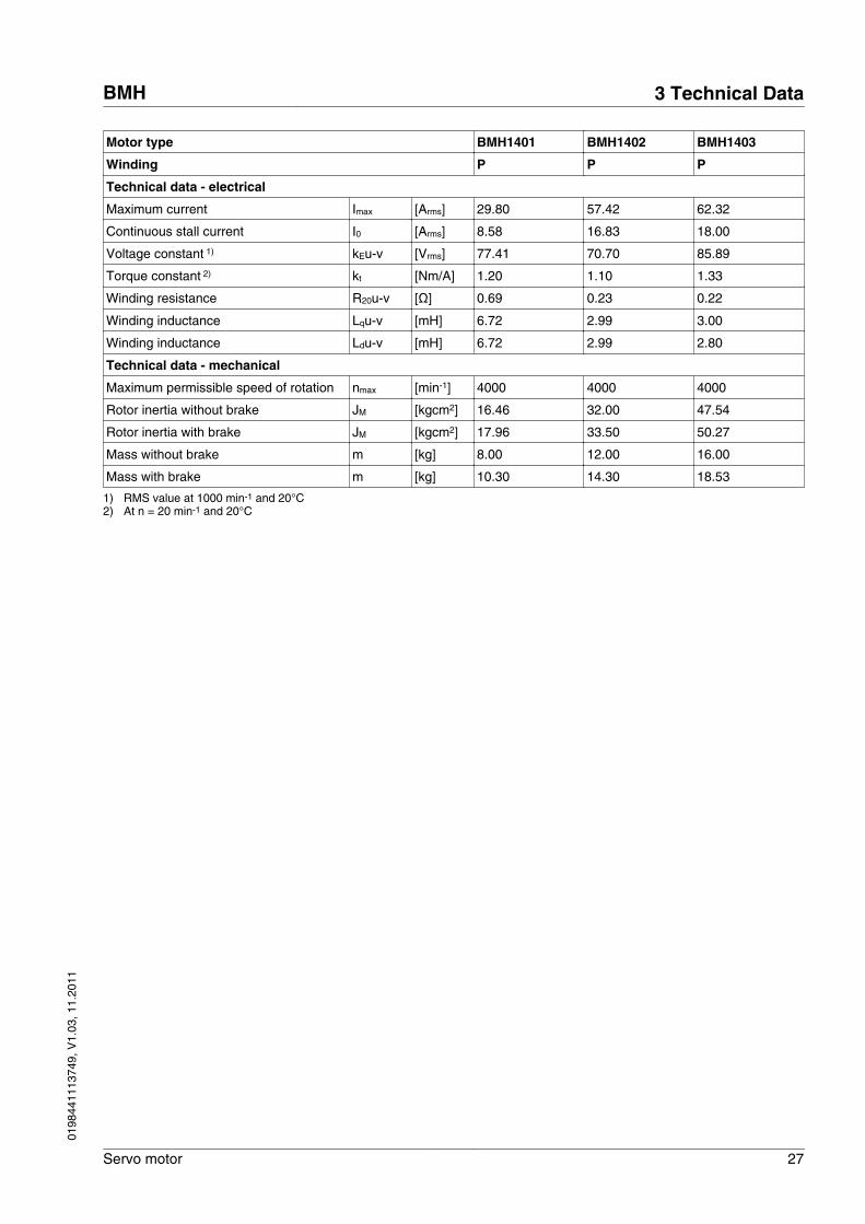
Motor type BMH1401 BMH1402 BMH1403
Winding P P P
Technical data - electrical
Maximum current Imax [Arms] 29.80 57.42 62.32
Continuous stall current I0 [Arms] 8.58 16.83 18.00
Voltage constant 1) kEu-v [Vrms] 77.41 70.70 85.89
Torque constant 2) kt [Nm/A] 1.20 1.10 1.33
Winding resistance R20u-v [Ω] 0.69 0.23 0.22
Winding inductance Lqu-v [mH] 6.72 2.99 3.00
Winding inductance Ldu-v [mH] 6.72 2.99 2.80
Technical data - mechanical
Maximum permissible speed of rotation nmax [min-1] 4000 4000 4000
Rotor inertia without brake JM [kgcm2] 16.46 32.00 47.54
Rotor inertia with brake JM [kgcm2] 17.96 33.50 50.27
Mass without brake m [kg] 8.00 12.00 16.00
Mass with brake m [kg] 10.30 14.30 18.53
1) RMS value at 1000 min-1 and 20°C2) At n = 20 min-1 and 20°C
BMH 3 Technical Data
Servo motor 27
0198
4411
1374
9, V
1.03
, 11.
2011
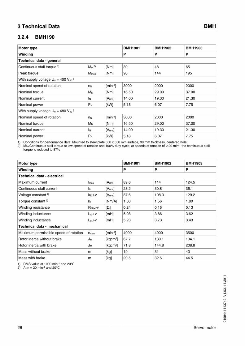
3.2.4 BMH190
Motor type BMH1901 BMH1902 BMH1903
Winding P P P
Technical data - general
Continuous stall torque 1) M0 2) [Nm] 30 48 65
Peak torque Mmax [Nm] 90 144 195
With supply voltage Un = 400 Vac )
Nominal speed of rotation nN [min-1] 3000 2000 2000
Nominal torque MN [Nm] 16.50 29.00 37.00
Nominal current IN [Arms] 14.00 19.30 21.30
Nominal power PN [kW] 5.18 6.07 7.75
With supply voltage Un = 480 Vac )
Nominal speed of rotation nN [min-1] 3000 2000 2000
Nominal torque MN [Nm] 16.50 29.00 37.00
Nominal current IN [Arms] 14.00 19.30 21.30
Nominal power PN [kW] 5.18 6.07 7.75
1) Conditions for performance data: Mounted to steel plate 550 x 550 mm surface, 30 mm thickness, centered hole.2) M0=Continuous stall torque at low speed of rotation and 100% duty cycle; at speeds of rotation of < 20 min-1 the continuous stall
torque is reduced to 87%
Motor type BMH1901 BMH1902 BMH1903
Winding P P P
Technical data - electrical
Maximum current Imax [Arms] 89.6 114 124.5
Continuous stall current I0 [Arms] 23.2 30.8 36.1
Voltage constant 1) kEu-v [Vrms] 87.6 108.3 129.2
Torque constant 2) kt [Nm/A] 1.30 1.56 1.80
Winding resistance R20u-v [Ω] 0.24 0.15 0.13
Winding inductance Lqu-v [mH] 5.08 3.86 3.62
Winding inductance Ldu-v [mH] 5.23 3.73 3.43
Technical data - mechanical
Maximum permissible speed of rotation nmax [min-1] 4000 4000 3500
Rotor inertia without brake JM [kgcm2] 67.7 130.1 194.1
Rotor inertia with brake JM [kgcm2] 71.8 144.8 208.8
Mass without brake m [kg] 19 31 43
Mass with brake m [kg] 20.5 32.5 44.5
1) RMS value at 1000 min-1 and 20°C2) At n = 20 min-1 and 20°C
3 Technical Data BMH
28 Servo motor
0198
4411
1374
9, V
1.03
, 11.
2011
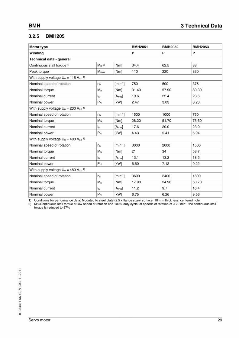
3.2.5 BMH205
Motor type BMH2051 BMH2052 BMH2053
Winding P P P
Technical data - general
Continuous stall torque 1) M0 2) [Nm] 34.4 62.5 88
Peak torque Mmax [Nm] 110 220 330
With supply voltage Un = 115 Vac 1)
Nominal speed of rotation nN [min-1] 750 500 375
Nominal torque MN [Nm] 31.40 57.90 80.30
Nominal current IN [Arms] 19.6 22.4 23.6
Nominal power PN [kW] 2.47 3.03 3.23
With supply voltage Un = 230 Vac 1)
Nominal speed of rotation nN [min-1] 1500 1000 750
Nominal torque MN [Nm] 28.20 51.70 75.60
Nominal current IN [Arms] 17.6 20.0 23.0
Nominal power PN [kW] 4.43 5.41 5.94
With supply voltage Un = 400 Vac 1)
Nominal speed of rotation nN [min-1] 3000 2000 1500
Nominal torque MN [Nm] 21 34 58.7
Nominal current IN [Arms] 13.1 13.2 18.5
Nominal power PN [kW] 6.60 7.12 9.22
With supply voltage Un = 480 Vac 1)
Nominal speed of rotation nN [min-1] 3600 2400 1800
Nominal torque MN [Nm] 17.90 24.90 50.70
Nominal current IN [Arms] 11.2 9.7 16.4
Nominal power PN [kW] 6.75 6.26 9.56
1) Conditions for performance data: Mounted to steel plate (2.5 x flange size)2 surface, 10 mm thickness, centered hole.2) M0=Continuous stall torque at low speed of rotation and 100% duty cycle; at speeds of rotation of < 20 min-1 the continuous stall
torque is reduced to 87%
BMH 3 Technical Data
Servo motor 29
0198
4411
1374
9, V
1.03
, 11.
2011
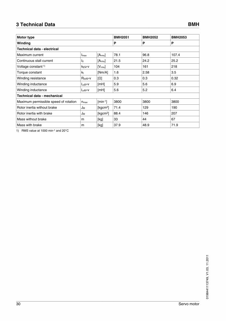
Motor type BMH2051 BMH2052 BMH2053
Winding P P P
Technical data - electrical
Maximum current Imax [Arms] 78.1 96.8 107.4
Continuous stall current I0 [Arms] 21.5 24.2 25.2
Voltage constant 1) kEu-v [Vrms] 104 161 218
Torque constant kt [Nm/A] 1.6 2.58 3.5
Winding resistance R20u-v [Ω] 0.3 0.3 0.32
Winding inductance Lqu-v [mH] 5.9 5.6 6.9
Winding inductance Ldu-v [mH] 5.6 5.2 6.4
Technical data - mechanical
Maximum permissible speed of rotation nmax [min-1] 3800 3800 3800
Rotor inertia without brake JM [kgcm2] 71.4 129 190
Rotor inertia with brake JM [kgcm2] 88.4 146 207
Mass without brake m [kg] 33 44 67
Mass with brake m [kg] 37.9 48.9 71.9
1) RMS value at 1000 min-1 and 20°C
3 Technical Data BMH
30 Servo motor
0198
4411
1374
9, V
1.03
, 11.
2011
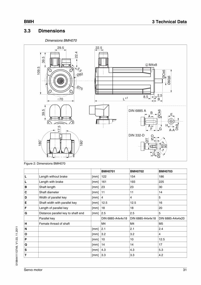
3.3 Dimensions
Dimensions BMH070
29.5
5.5
Ø82
Ø75
22.4
39.5
109.
5
70
22.5
L
Ø60
j6ØC
k6
8.5 2.5
M4x8
17.5
180˚
180˚
B
F G
ØC
k6BA
A
E
A-A
DIN 332-D
DIN 6885 A
Dh9H
±1
39.5
ØS
NO
Q
60˚
90˚Ø
TP
Figure 2: Dimensions BMH070
BMH0701 BMH0702 BMH0703
L Length without brake [mm] 122 154 186
L Length with brake [mm] 161 193 225
B Shaft length [mm] 23 23 30
C Shaft diameter [mm] 11 11 14
D Width of parallel key [mm] 4 4 5
E Shaft width with parallel key [mm] 12.5 12.5 16
F Length of parallel key [mm] 18 18 20
G Distance parallel key to shaft end [mm] 2.5 2.5 5
Parallel key DIN 6885-A4x4x18 DIN 6885-A4x4x18 DIN 6885-A4x4x20
H Female thread of shaft M4 M4 M5
N [mm] 2.1 2.1 2.4
O [mm] 3.2 3.2 4
P [mm] 10 10 12.5
Q [mm] 14 14 17
S [mm] 4.3 4.3 5.3
T [mm] 3.3 3.3 4.2
BMH 3 Technical Data
Servo motor 31
0198
4411
1374
9, V
1.03
, 11.
2011
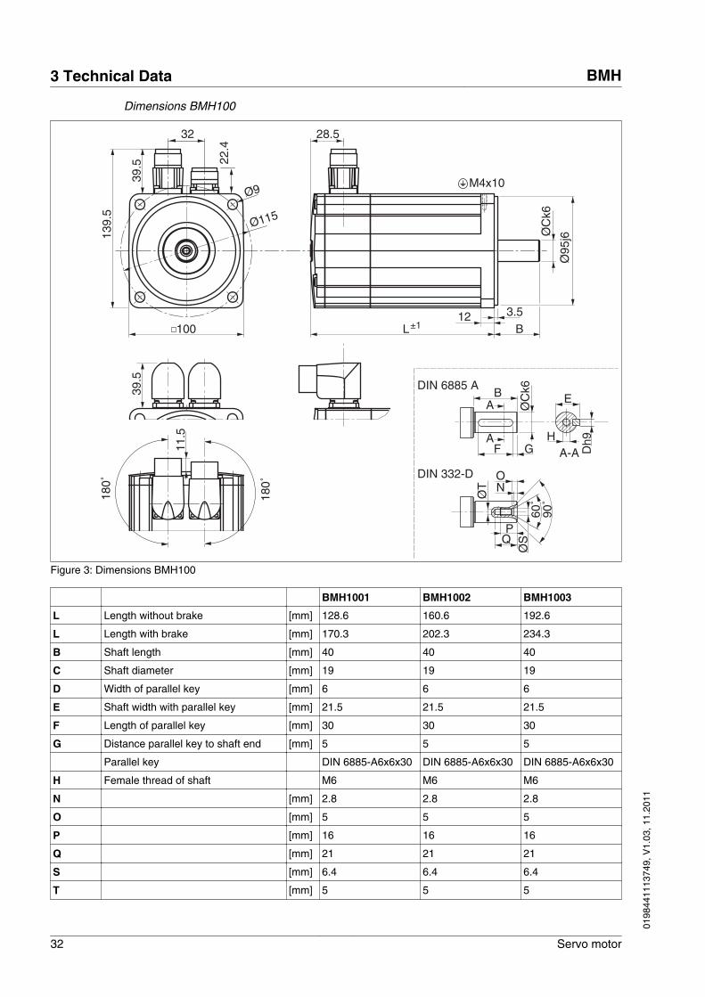
Dimensions BMH100
32
22.4
39.5
139.
5
100
Ø115
Ø9
3.512
28.5
Ø95
j6ØC
k6
B
M4x1011
.5
180˚
180˚
L
F G
ØC
k6BA
A
E
A-A
DIN 6885 A
Dh9H
DIN 332-D
±1
39.5
ØS
NO
Q60
˚90
˚ØT
P
Figure 3: Dimensions BMH100
BMH1001 BMH1002 BMH1003
L Length without brake [mm] 128.6 160.6 192.6
L Length with brake [mm] 170.3 202.3 234.3
B Shaft length [mm] 40 40 40
C Shaft diameter [mm] 19 19 19
D Width of parallel key [mm] 6 6 6
E Shaft width with parallel key [mm] 21.5 21.5 21.5
F Length of parallel key [mm] 30 30 30
G Distance parallel key to shaft end [mm] 5 5 5
Parallel key DIN 6885-A6x6x30 DIN 6885-A6x6x30 DIN 6885-A6x6x30
H Female thread of shaft M6 M6 M6
N [mm] 2.8 2.8 2.8
O [mm] 5 5 5
P [mm] 16 16 16
Q [mm] 21 21 21
S [mm] 6.4 6.4 6.4
T [mm] 5 5 5
3 Technical Data BMH
32 Servo motor
0198
4411
1374
9, V
1.03
, 11.
2011
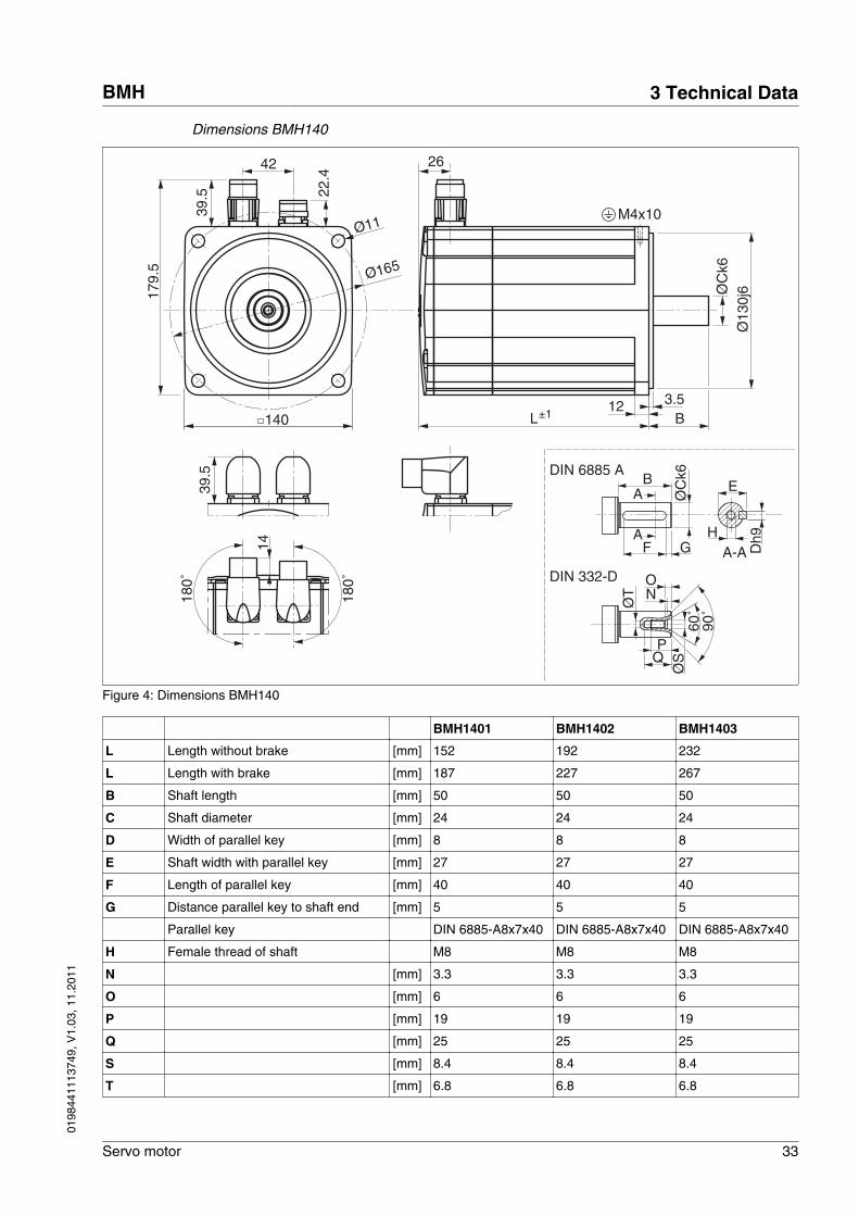
Dimensions BMH140
42
22.4
39.5
179.
5
140
Ø165
Ø11
3.5B
12L
26
ØC
k6Ø
130j
6
M4x10
14
180˚
180˚
F G
ØC
k6BA
A
E
A-A
DIN 6885 A
Dh9H
DIN 332-D
±1
39.5
ØS
NO
Q
60˚
90˚Ø
TP
Figure 4: Dimensions BMH140
BMH1401 BMH1402 BMH1403
L Length without brake [mm] 152 192 232
L Length with brake [mm] 187 227 267
B Shaft length [mm] 50 50 50
C Shaft diameter [mm] 24 24 24
D Width of parallel key [mm] 8 8 8
E Shaft width with parallel key [mm] 27 27 27
F Length of parallel key [mm] 40 40 40
G Distance parallel key to shaft end [mm] 5 5 5
Parallel key DIN 6885-A8x7x40 DIN 6885-A8x7x40 DIN 6885-A8x7x40
H Female thread of shaft M8 M8 M8
N [mm] 3.3 3.3 3.3
O [mm] 6 6 6
P [mm] 19 19 19
Q [mm] 25 25 25
S [mm] 8.4 8.4 8.4
T [mm] 6.8 6.8 6.8
BMH 3 Technical Data
Servo motor 33
0198
4411
1374
9, V
1.03
, 11.
2011
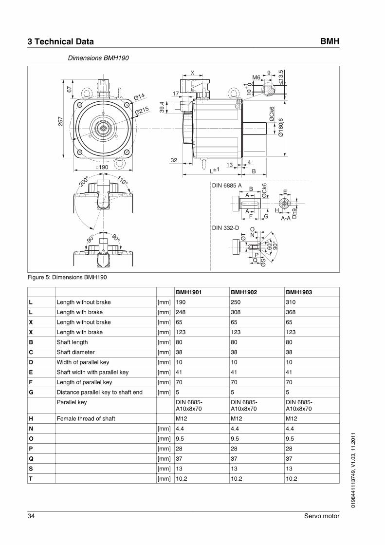
Dimensions BMH190
67
257
190
Ø215
Ø14
4
BL
ØC
k6
Ø18
0j6
F G
ØC
k6BA
A
E
A-A
DIN 6885 A
Dh9H
DIN 332-D
±113
32
17
39.4
ØS
NO
Q
60°
90°Ø
T
P10
+1 0
M6 13.59
vl
X
200°
90° 90°
110°
Figure 5: Dimensions BMH190
BMH1901 BMH1902 BMH1903
L Length without brake [mm] 190 250 310
L Length with brake [mm] 248 308 368
X Length without brake [mm] 65 65 65
X Length with brake [mm] 123 123 123
B Shaft length [mm] 80 80 80
C Shaft diameter [mm] 38 38 38
D Width of parallel key [mm] 10 10 10
E Shaft width with parallel key [mm] 41 41 41
F Length of parallel key [mm] 70 70 70
G Distance parallel key to shaft end [mm] 5 5 5
Parallel key DIN 6885-A10x8x70
DIN 6885-A10x8x70
DIN 6885-A10x8x70
H Female thread of shaft M12 M12 M12
N [mm] 4.4 4.4 4.4
O [mm] 9.5 9.5 9.5
P [mm] 28 28 28
Q [mm] 37 37 37
S [mm] 13 13 13
T [mm] 10.2 10.2 10.2
3 Technical Data BMH
34 Servo motor
0198
4411
1374
9, V
1.03
, 11.
2011
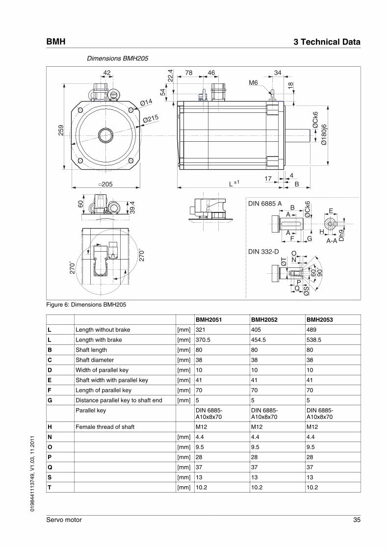
Dimensions BMH205
42
22.4
54
259
205
Ø215
Ø14
4B
17L
78
ØC
k6Ø
180j
6
270˚
270˚
46
39.460
±1
18
34
M6
F G
ØC
k6BA
A
E
A-A
DIN 6885 A
Dh9H
DIN 332-D
ØS
NO
Q
60˚
90˚Ø
TP
Figure 6: Dimensions BMH205
BMH2051 BMH2052 BMH2053
L Length without brake [mm] 321 405 489
L Length with brake [mm] 370.5 454.5 538.5
B Shaft length [mm] 80 80 80
C Shaft diameter [mm] 38 38 38
D Width of parallel key [mm] 10 10 10
E Shaft width with parallel key [mm] 41 41 41
F Length of parallel key [mm] 70 70 70
G Distance parallel key to shaft end [mm] 5 5 5
Parallel key DIN 6885-A10x8x70
DIN 6885-A10x8x70
DIN 6885-A10x8x70
H Female thread of shaft M12 M12 M12
N [mm] 4.4 4.4 4.4
O [mm] 9.5 9.5 9.5
P [mm] 28 28 28
Q [mm] 37 37 37
S [mm] 13 13 13
T [mm] 10.2 10.2 10.2
BMH 3 Technical Data
Servo motor 35
0198
4411
1374
9, V
1.03
, 11.
2011
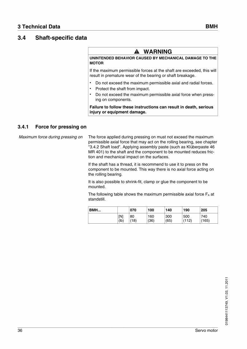
3.4 Shaft-specific data
WARNINGUNINTENDED BEHAVIOR CAUSED BY MECHANICAL DAMAGE TO THEMOTOR
If the maximum permissible forces at the shaft are exceeded, this willresult in premature wear of the bearing or shaft breakage.
• Do not exceed the maximum permissible axial and radial forces.• Protect the shaft from impact.• Do not exceed the maximum permissible axial force when press-
ing on components.
Failure to follow these instructions can result in death, seriousinjury or equipment damage.
3.4.1 Force for pressing on
Maximum force during pressing on The force applied during pressing on must not exceed the maximumpermissible axial force that may act on the rolling bearing, see chapter"3.4.2 Shaft load". Applying assembly paste (such as Klüberpaste 46MR 401) to the shaft and the component to be mounted reduces fric-tion and mechanical impact on the surfaces.
If the shaft has a thread, it is recommend to use it to press on thecomponent to be mounted. This way there is no axial force acting onthe rolling bearing.
It is also possible to shrink-fit, clamp or glue the component to bemounted.
The following table shows the maximum permissible axial force FA atstandstill.
BMH... 070 100 140 190 205
[N] (lb)
80(18)
160(36)
300(65)
500(112)
740(165)
3 Technical Data BMH
36 Servo motor
0198
4411
1374
9, V
1.03
, 11.
2011
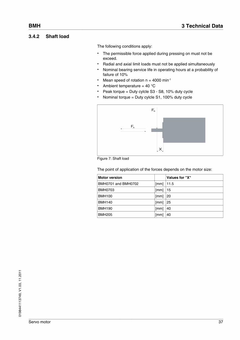
3.4.2 Shaft load
The following conditions apply:
• The permissible force applied during pressing on must not beexceed.
• Radial and axial limit loads must not be applied simultaneously• Nominal bearing service life in operating hours at a probability of
failure of 10%• Mean speed of rotation n = 4000 min-1 • Ambient temperature = 40 °C• Peak torque = Duty cylcle S3 - S8, 10% duty cycle• Nominal torque = Duty cylcle S1, 100% duty cycle
X
FA
FR
Figure 7: Shaft load
The point of application of the forces depends on the motor size:
Motor version Values for "X"
BMH0701 and BMH0702 [mm] 11.5
BMH0703 [mm] 15
BMH100 [mm] 20
BMH140 [mm] 25
BMH190 [mm] 40
BMH205 [mm] 40
BMH 3 Technical Data
Servo motor 37
0198
4411
1374
9, V
1.03
, 11.
2011
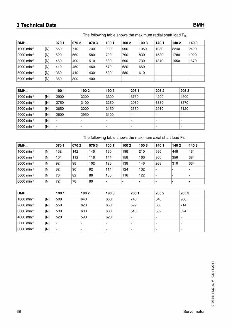
The following table shows the maximum radial shaft load FR.
BMH... 070 1 070 2 070 3 100 1 100 2 100 3 140 1 140 2 140 3
1000 min-1 [N] 660 710 730 900 990 1050 1930 2240 2420
2000 min-1 [N] 520 560 580 720 790 830 1530 1780 1920
3000 min-1 [N] 460 490 510 630 690 730 1340 1550 1670
4000 min-1 [N] 410 450 460 570 620 660 - - -
5000 min-1 [N] 380 410 430 530 580 610 - - -
6000 min-1 [N] 360 390 400 - - - - - -
BMH... 190 1 190 2 190 3 205 1 205 2 205 3
1000 min-1 [N] 2900 3200 3300 3730 4200 4500
2000 min-1 [N] 2750 3100 3250 2960 3330 3570
3000 min-1 [N] 2650 3000 3150 2580 2910 3120
4000 min-1 [N] 2600 2950 3100 - - -
5000 min-1 [N] - - - - - -
6000 min-1 [N] - - - - - -
The following table shows the maximum axial shaft load FA.
BMH... 070 1 070 2 070 3 100 1 100 2 100 3 140 1 140 2 140 3
1000 min-1 [N] 132 142 146 180 198 210 386 448 484
2000 min-1 [N] 104 112 116 144 158 166 306 356 384
3000 min-1 [N] 92 98 102 126 138 146 268 310 334
4000 min-1 [N] 82 90 92 114 124 132 - - -
5000 min-1 [N] 76 82 86 106 116 122 - - -
6000 min-1 [N] 72 78 80 - - - - - -
BMH... 190 1 190 2 190 3 205 1 205 2 205 3
1000 min-1 [N] 580 640 660 746 840 900
2000 min-1 [N] 550 620 650 592 666 714
3000 min-1 [N] 530 600 630 516 582 624
4000 min-1 [N] 520 590 620 - - -
5000 min-1 [N] - - - - - -
6000 min-1 [N] - - - - - -
3 Technical Data BMH
38 Servo motor
0198
4411
1374
9, V
1.03
, 11.
2011
3.5 Options
3.5.1 Holding brake
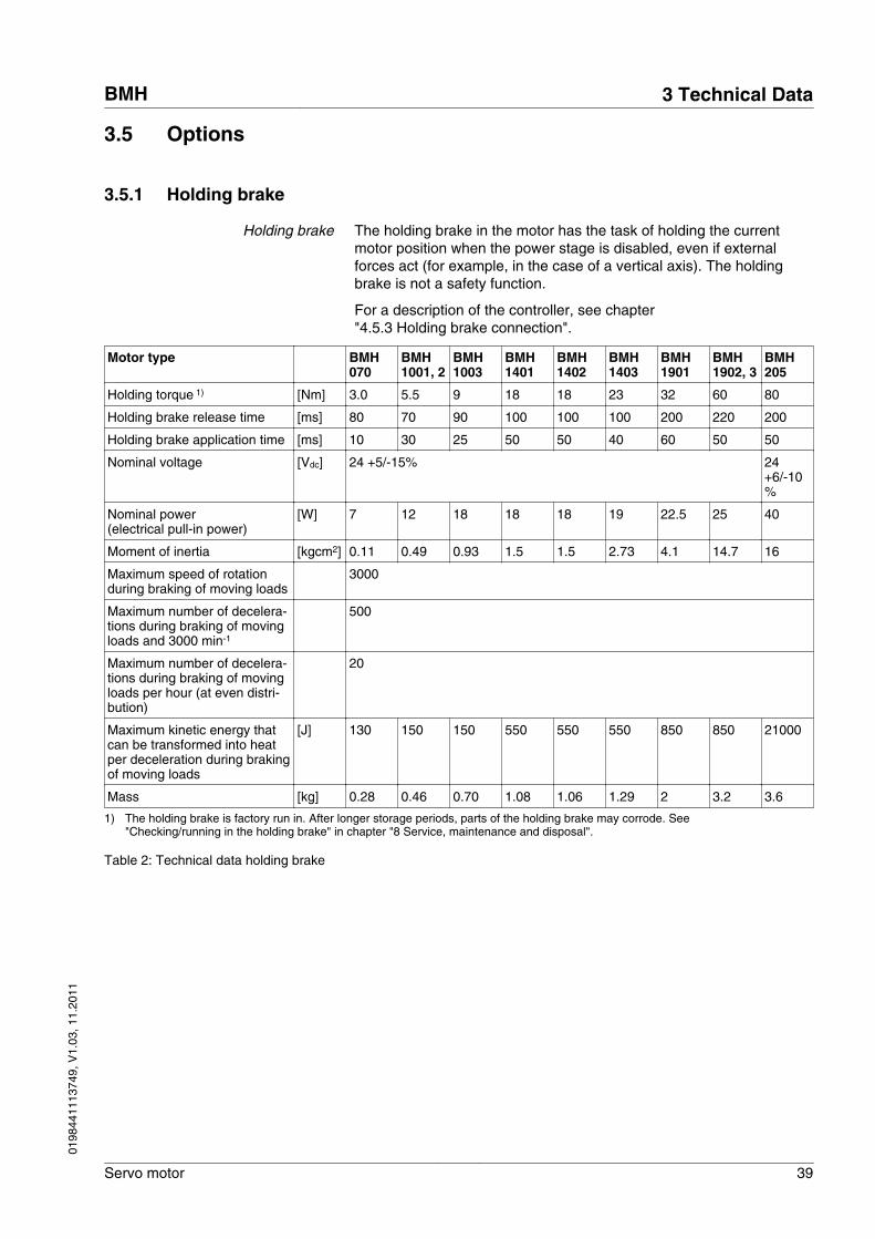
Holding brake The holding brake in the motor has the task of holding the currentmotor position when the power stage is disabled, even if externalforces act (for example, in the case of a vertical axis). The holdingbrake is not a safety function.
For a description of the controller, see chapter"4.5.3 Holding brake connection".
Motor type BMH070
BMH1001, 2
BMH1003
BMH1401
BMH1402
BMH1403
BMH1901
BMH1902, 3
BMH205
Holding torque 1) [Nm] 3.0 5.5 9 18 18 23 32 60 80
Holding brake release time [ms] 80 70 90 100 100 100 200 220 200
Holding brake application time [ms] 10 30 25 50 50 40 60 50 50
Nominal voltage [Vdc] 24 +5/-15% 24+6/-10%
Nominal power(electrical pull-in power)
[W] 7 12 18 18 18 19 22.5 25 40
Moment of inertia [kgcm2] 0.11 0.49 0.93 1.5 1.5 2.73 4.1 14.7 16
Maximum speed of rotationduring braking of moving loads
3000
Maximum number of decelera-tions during braking of movingloads and 3000 min-1
500
Maximum number of decelera-tions during braking of movingloads per hour (at even distri-bution)
20
Maximum kinetic energy thatcan be transformed into heatper deceleration during brakingof moving loads
[J] 130 150 150 550 550 550 850 850 21000
Mass [kg] 0.28 0.46 0.70 1.08 1.06 1.29 2 3.2 3.6
1) The holding brake is factory run in. After longer storage periods, parts of the holding brake may corrode. See"Checking/running in the holding brake" in chapter "8 Service, maintenance and disposal".
Table 2: Technical data holding brake
BMH 3 Technical Data
Servo motor 39
0198
4411
1374
9, V
1.03
, 11.
2011
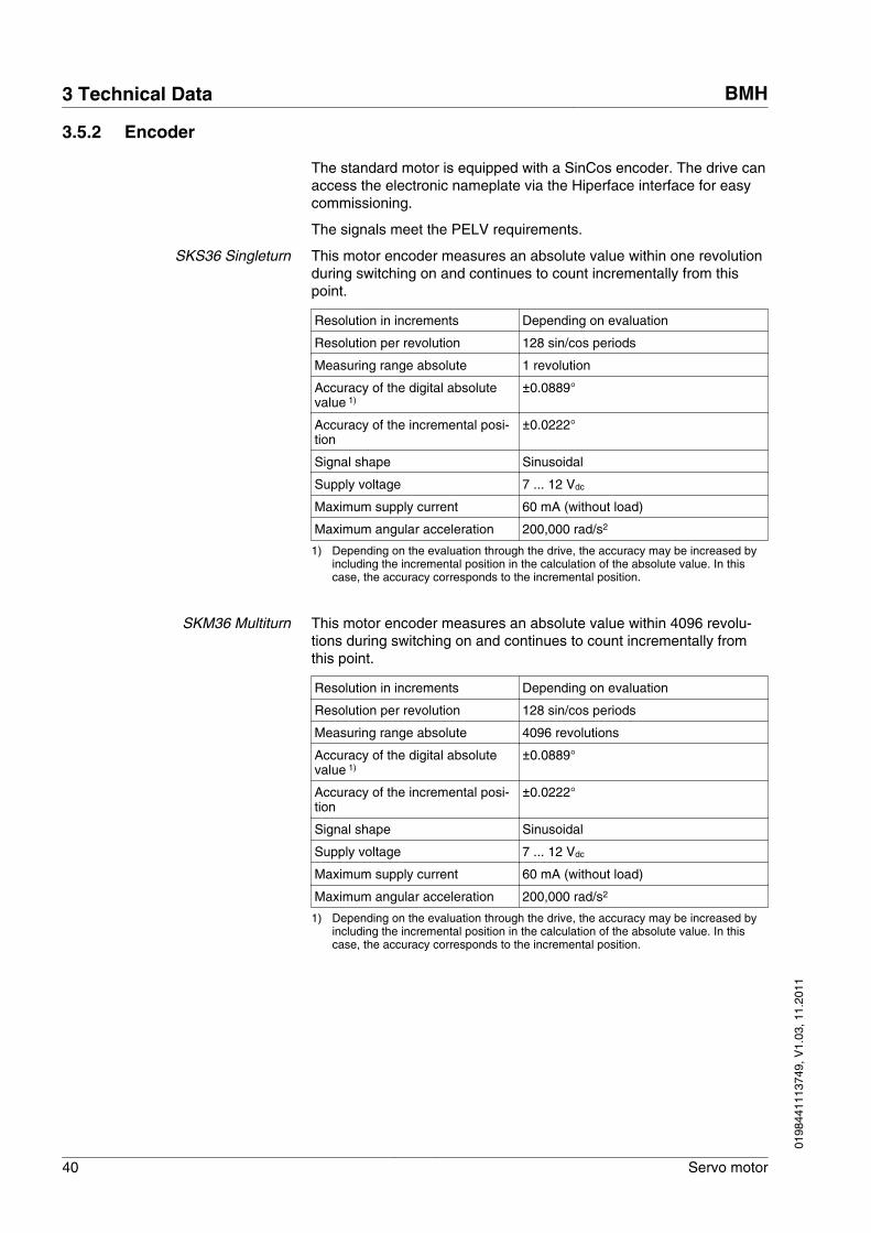
3.5.2 Encoder
The standard motor is equipped with a SinCos encoder. The drive canaccess the electronic nameplate via the Hiperface interface for easycommissioning.
The signals meet the PELV requirements.
SKS36 Singleturn This motor encoder measures an absolute value within one revolutionduring switching on and continues to count incrementally from thispoint.
Resolution in increments Depending on evaluation
Resolution per revolution 128 sin/cos periods
Measuring range absolute 1 revolution
Accuracy of the digital absolutevalue 1)
±0.0889°
Accuracy of the incremental posi-tion
±0.0222°
Signal shape Sinusoidal
Supply voltage 7 ... 12 Vdc
Maximum supply current 60 mA (without load)
Maximum angular acceleration 200,000 rad/s2
1) Depending on the evaluation through the drive, the accuracy may be increased byincluding the incremental position in the calculation of the absolute value. In thiscase, the accuracy corresponds to the incremental position.
SKM36 Multiturn This motor encoder measures an absolute value within 4096 revolu-tions during switching on and continues to count incrementally fromthis point.
Resolution in increments Depending on evaluation
Resolution per revolution 128 sin/cos periods
Measuring range absolute 4096 revolutions
Accuracy of the digital absolutevalue 1)
±0.0889°
Accuracy of the incremental posi-tion
±0.0222°
Signal shape Sinusoidal
Supply voltage 7 ... 12 Vdc
Maximum supply current 60 mA (without load)
Maximum angular acceleration 200,000 rad/s2
1) Depending on the evaluation through the drive, the accuracy may be increased byincluding the incremental position in the calculation of the absolute value. In thiscase, the accuracy corresponds to the incremental position.
3 Technical Data BMH
40 Servo motor
0198
4411
1374
9, V
1.03
, 11.
2011
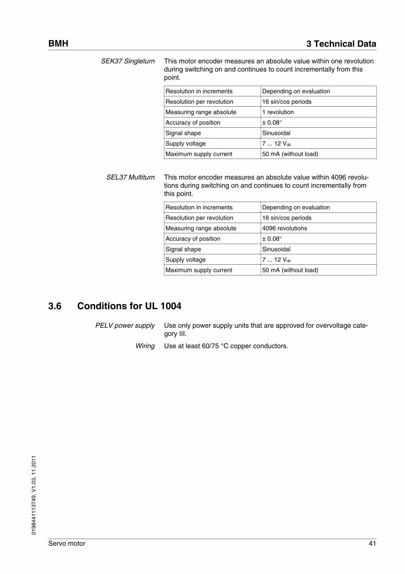
SEK37 Singleturn This motor encoder measures an absolute value within one revolutionduring switching on and continues to count incrementally from thispoint.
Resolution in increments Depending on evaluation
Resolution per revolution 16 sin/cos periods
Measuring range absolute 1 revolution
Accuracy of position ± 0.08°
Signal shape Sinusoidal
Supply voltage 7 ... 12 Vdc
Maximum supply current 50 mA (without load)
SEL37 Multiturn This motor encoder measures an absolute value within 4096 revolu-tions during switching on and continues to count incrementally fromthis point.
Resolution in increments Depending on evaluation
Resolution per revolution 16 sin/cos periods
Measuring range absolute 4096 revolutions
Accuracy of position ± 0.08°
Signal shape Sinusoidal
Supply voltage 7 ... 12 Vdc
Maximum supply current 50 mA (without load)
3.6 Conditions for UL 1004
PELV power supply Use only power supply units that are approved for overvoltage cate-gory III.
Wiring Use at least 60/75 °C copper conductors.
BMH 3 Technical Data
Servo motor 41
0198
4411
1374
9, V
1.03
, 11.
2011
3.7 Certifications
Product certifications:
Certified by Assigned number Validity
UL File E 208613 -
3 Technical Data BMH
42 Servo motor
0198
4411
1374
9, V
1.03
, 11.
2011
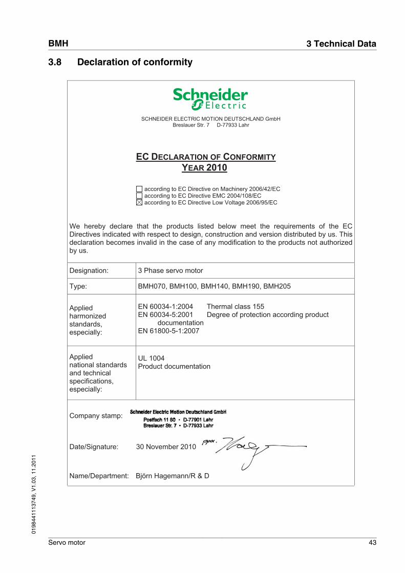
3.8 Declaration of conformity
SCHNEIDER ELECTRIC MOTION DEUTSCHLAND GmbH
Breslauer Str. 7 D-77933 Lahr
EC DECLARATION OF CONFORMITY
YEAR 2010
according to EC Directive on Machinery 2006/42/EC according to EC Directive EMC 2004/108/EC according to EC Directive Low Voltage 2006/95/EC
We hereby declare that the products listed below meet the requirements of the EC Directives indicated with respect to design, construction and version distributed by us. This declaration becomes invalid in the case of any modification to the products not authorized by us.
Designation: 3 Phase servo motor
Type: BMH070, BMH100, BMH140, BMH190, BMH205
Applied harmonized standards, especially:
EN 60034-1:2004 Thermal class 155 EN 60034-5:2001 Degree of protection according product documentation EN 61800-5-1:2007
Applied national standards and technical specifications, especially:
UL 1004 Product documentation
Company stamp:
Date/Signature: 30 November 2010
Name/Department:
Björn Hagemann/R & D
BMH 3 Technical Data
Servo motor 43
0198
4411
1374
9, V
1.03
, 11.
2011
3 Technical Data BMH
44 Servo motor
0198
4411
1374
9, V
1.03
, 11.
2011
4 Installation
4
WARNINGGREAT MASS OR FALLING PARTS
The motor can have an unexpectedly great mass.
• Consider the mass of the motor when mounting it. It may be nec-essary to use a suitable crane.
• Use personal protective equipment (for example, safety shoesand protective gloves).
• Mount the motor in such a way (tightening torque, securingscrews) that it cannot come loose even in the case of fast accel-eration or continuous vibration.
Failure to follow these instructions can result in death, seriousinjury or equipment damage.
WARNINGSTRONG ELECTROMAGNETIC FIELDS
Motors can generate strong local electrical and magnetic fields. Thiscan cause interference in sensitive devices.
• Keep persons with implants such as pacemakers away from themotor.
• Do not place any sensitive devices close to the motor.
Failure to follow these instructions can result in death, seriousinjury or equipment damage.
WARNINGUNEXPECTED BEHAVIOR CAUSED BY DAMAGE OR FOREIGNOBJECTS
Damage to the product as well as foreign objects, deposits or humid-ity can cause unexpected behavior.
• Do not use damaged products.• Keep foreign objects from getting into the product.• Verify correct seat of seals and cable entries.
Failure to follow these instructions can result in death, seriousinjury or equipment damage.
BMH 4 Installation
Servo motor 45
0198
4411
1374
9, V
1.03
, 11.
2011
WARNINGHOT SURFACES
The heat sink at the product may heat up to over 100°C (212°F) dur-ing operation.
• Avoid contact with the hot heat sink.• Do not allow flammable or heat-sensitive parts in the immediate
vicinity.• Consider the measures for heat dissipation described.
Failure to follow these instructions can result in death or seri-ous injury.
CAUTIONDAMAGE CAUSED BY IMPROPER APPLICATION OF FORCES
If the motor is improperly subjected to loads, it can be damaged orfall down.
• Do not step onto the motor.• Avoid improper use by means of safeguards at the machine or
safety instructions.
Failure to follow these instructions can result in injury or equip-ment damage.
4 Installation BMH
46 Servo motor
0198
4411
1374
9, V
1.03
, 11.
2011
4.1 Overview of procedure
Chapter Page
"4.2 Electromagnetic compatibility, EMC" 47
"4.3 Before mounting" 49
"4.4 Mounting the motor " 54
"4.5.2 Power and encoder connection" 64
"4.5.3 Holding brake connection" 70
▶ Finally, verify proper installation.
4.2 Electromagnetic compatibility, EMC
WARNINGSIGNAL AND DEVICE INTERFERENCE
Signal interference can cause unexpected responses of the device.
• Install the wiring in accordance with the EMC requirements.• Verify compliance with the EMC requirements.
Failure to follow these instructions can result in death, seriousinjury or equipment damage.
Pre-assembled motor cables and encoder cables in many differentlengths are available for the drive solutions. Contact your local salesoffice.
EMC requirement: Route motorcable separately
When planning the wiring, take into account the fact that the motorcable must be routed separately. The motor cable must be separatefrom the mains cable or the signal wires.
BMH 4 Installation
Servo motor 47
0198
4411
1374
9, V
1.03
, 11.
2011
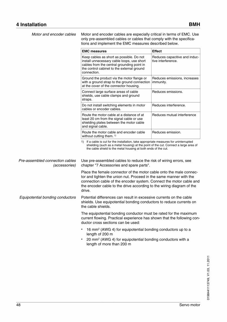
Motor and encoder cables Motor and encoder cables are especially critical in terms of EMC. Useonly pre-assembled cables or cables that comply with the specifica-tions and implement the EMC measures described below.
EMC measures Effect
Keep cables as short as possible. Do notinstall unnecessary cable loops, use shortcables from the central grounding point inthe control cabinet to the external groundconnection.
Reduces capacitive and induc-tive interference.
Ground the product via the motor flange orwith a ground strap to the ground connectionat the cover of the connector housing.
Reduces emissions, increasesimmunity.
Connect large surface areas of cableshields, use cable clamps and groundstraps.
Reduces emissions.
Do not install switching elements in motorcables or encoder cables.
Reduces interference.
Route the motor cable at a distance of atleast 20 cm from the signal cable or useshielding plates between the motor cableand signal cable.
Reduces mutual interference
Route the motor cable and encoder cablewithout cutting them. 1)
Reduces emission.
1) If a cable is cut for the installation, take appropriate measures for uninterruptedshielding (such as a metal housing) at the point of the cut. Connect a large area ofthe cable shield to the metal housing at both ends of the cut.
Pre-assembled connection cables(accessories)
Use pre-assembled cables to reduce the risk of wiring errors, seechapter "7 Accessories and spare parts".
Place the female connector of the motor cable onto the male connec-tor and tighten the union nut. Proceed in the same manner with theconnection cable of the encoder system. Connect the motor cable andthe encoder cable to the drive according to the wiring diagram of thedrive.
Equipotential bonding conductors Potential differences can result in excessive currents on the cableshields. Use equipotential bonding conductors to reduce currents onthe cable shields.
The equipotential bonding conductor must be rated for the maximumcurrent flowing. Practical experience has shown that the following con-ductor cross sections can be used:
• 16 mm2 (AWG 4) for equipotential bonding conductors up to alength of 200 m
• 20 mm2 (AWG 4) for equipotential bonding conductors with alength of more than 200 m
4 Installation BMH
48 Servo motor
0198
4411
1374
9, V
1.03
, 11.
2011
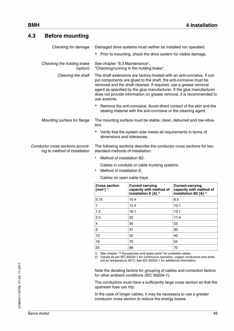
4.3 Before mounting
Checking for damage Damaged drive systems must neither be installed nor operated.
▶ Prior to mounting, check the drive system for visible damage.
Checking the holding brake(option)
See chapter "8.3 Maintenance","Checking/running in the holding brake".
Cleaning the shaft The shaft extensions are factory-treated with an anti-corrosive. If out-put components are glued to the shaft, the anti-corrosive must beremoved and the shaft cleaned. If required, use a grease removalagent as specified by the glue manufacturer. If the glue manufacturerdoes not provide information on grease removal, it is recommended touse acetone.
▶ Remove the anti-corrosive. Avoid direct contact of the skin and thesealing material with the anti-corrosive or the cleaning agent.
Mounting surface for flange The mounting surface must be stable, clean, deburred and low-vibra-tion.
▶ Verify that the system side meets all requirements in terms ofdimensions and tolerances.
Conductor cross sections accord-ing to method of installation
The following sections describe the conductor cross sections for twostandard methods of installation:
• Method of installation B2:
Cables in conduits or cable trunking systems• Method of installation E:
Cables on open cable trays
Cross section[mm2] 1)
Current carryingcapacity with method ofinstallation E [A] 2)
Current-carryingcapacity with method ofinstallation B2 [A] 2)
0.75 10.4 8.5
1 12.4 10.1
1.5 16.1 13.1
2.5 22 17.4
4 30 23
6 37 30
10 52 40
16 70 54
25 88 70
1) See chapter "7 Accessories and spare parts" for available cables.2) Values as per IEC 60204-1 for continuous operation, copper conductors and ambi-
ent air temperature 40°C; see IEC 60204-1 for additional information.
Note the derating factors for grouping of cables and correction factorsfor other ambient conditions (IEC 60204-1).
The conductors must have a sufficiently large cross section so that theupstream fuse can trip.
In the case of longer cables, it may be necessary to use a greaterconductor cross section to reduce the energy losses.
BMH 4 Installation
Servo motor 49
0198
4411
1374
9, V
1.03
, 11.
2011
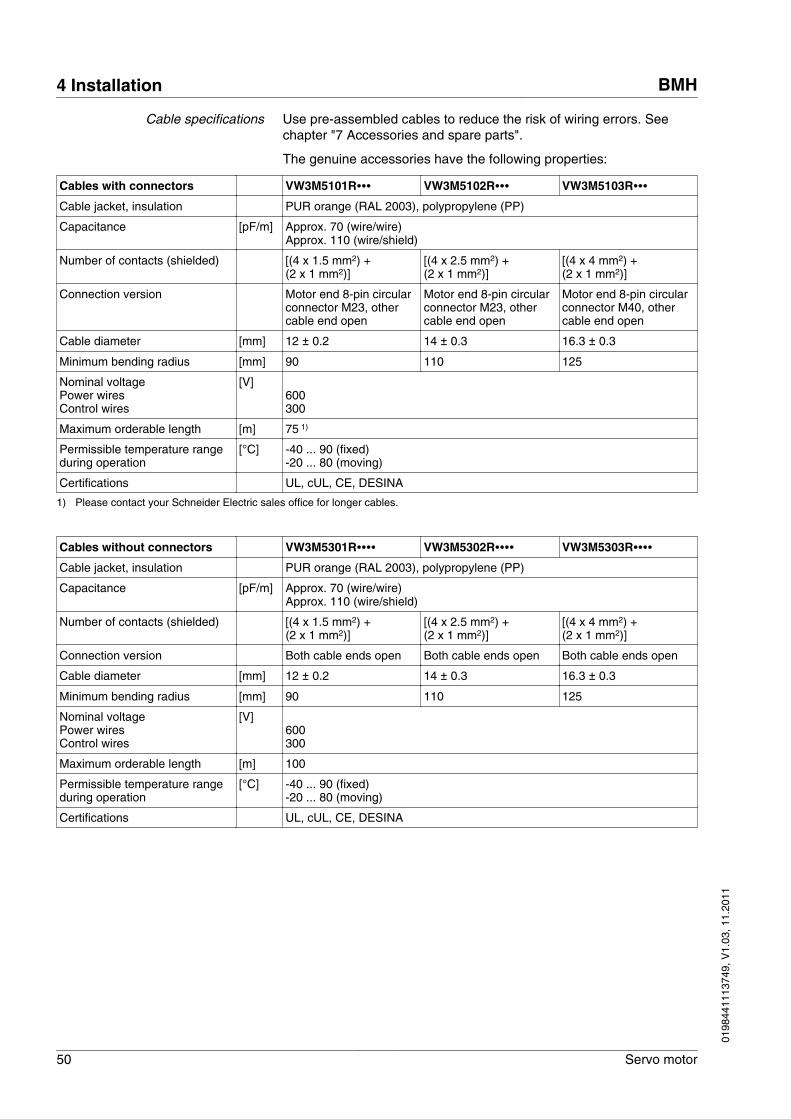
Cable specifications Use pre-assembled cables to reduce the risk of wiring errors. Seechapter "7 Accessories and spare parts".
The genuine accessories have the following properties:
Cables with connectors VW3M5101R∙∙∙ VW3M5102R∙∙∙ VW3M5103R∙∙∙Cable jacket, insulation PUR orange (RAL 2003), polypropylene (PP)
Capacitance [pF/m] Approx. 70 (wire/wire)Approx. 110 (wire/shield)
Number of contacts (shielded) [(4 x 1.5 mm2) + (2 x 1 mm2)]
[(4 x 2.5 mm2) + (2 x 1 mm2)]
[(4 x 4 mm2) + (2 x 1 mm2)]
Connection version Motor end 8-pin circularconnector M23, othercable end open
Motor end 8-pin circularconnector M23, othercable end open
Motor end 8-pin circularconnector M40, othercable end open
Cable diameter [mm] 12 ± 0.2 14 ± 0.3 16.3 ± 0.3
Minimum bending radius [mm] 90 110 125
Nominal voltagePower wiresControl wires
[V]600300
Maximum orderable length [m] 75 1)
Permissible temperature rangeduring operation
[°C] -40 ... 90 (fixed)-20 ... 80 (moving)
Certifications UL, cUL, CE, DESINA
1) Please contact your Schneider Electric sales office for longer cables.
Cables without connectors VW3M5301R∙∙∙∙ VW3M5302R∙∙∙∙ VW3M5303R∙∙∙∙Cable jacket, insulation PUR orange (RAL 2003), polypropylene (PP)
Capacitance [pF/m] Approx. 70 (wire/wire)Approx. 110 (wire/shield)
Number of contacts (shielded) [(4 x 1.5 mm2) + (2 x 1 mm2)]
[(4 x 2.5 mm2) + (2 x 1 mm2)]
[(4 x 4 mm2) + (2 x 1 mm2)]
Connection version Both cable ends open Both cable ends open Both cable ends open
Cable diameter [mm] 12 ± 0.2 14 ± 0.3 16.3 ± 0.3
Minimum bending radius [mm] 90 110 125
Nominal voltagePower wiresControl wires
[V]600300
Maximum orderable length [m] 100
Permissible temperature rangeduring operation
[°C] -40 ... 90 (fixed)-20 ... 80 (moving)
Certifications UL, cUL, CE, DESINA
4 Installation BMH
50 Servo motor
0198
4411
1374
9, V
1.03
, 11.
2011
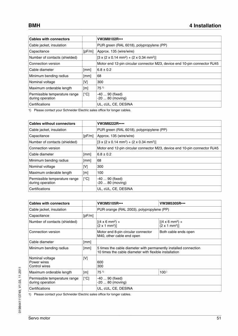
Cables with connectors VW3M8102R∙∙∙Cable jacket, insulation PUR green (RAL 6018), polypropylene (PP)
Capacitance [pF/m] Approx. 135 (wire/wire)
Number of contacts (shielded) [3 x (2 x 0.14 mm2) + (2 x 0.34 mm2)]
Connection version Motor end 12-pin circular connector M23, device end 10-pin connector RJ45
Cable diameter [mm] 6.8 ± 0.2
Minimum bending radius [mm] 68
Nominal voltage [V] 300
Maximum orderable length [m] 75 1)
Permissible temperature rangeduring operation
[°C] -40 ... 90 (fixed)-20 ... 80 (moving)
Certifications UL, cUL, CE, DESINA
1) Please contact your Schneider Electric sales office for longer cables.
Cables without connectors VW3M8222R∙∙∙∙Cable jacket, insulation PUR green (RAL 6018), polypropylene (PP)
Capacitance [pF/m] Approx. 135 (wire/wire)
Number of contacts (shielded) [3 x (2 x 0.14 mm2) + (2 x 0.34 mm2)]
Connection version Motor end 12-pin circular connector M23, device end 10-pin connector RJ45
Cable diameter [mm] 6.8 ± 0.2
Minimum bending radius [mm] 68
Nominal voltage [V] 300
Maximum orderable length [m] 100
Permissible temperature rangeduring operation
[°C] -40 ... 90 (fixed)-20 ... 80 (moving)
Certifications UL, cUL, CE, DESINA
Cables with connectors VW3M5105R∙∙∙ VW3M5305R∙∙∙Cable jacket, insulation PUR orange (RAL 2003), polypropylene (PP)
Capacitance [pF/m]
Number of contacts (shielded) [(4 x 6 mm2) + (2 x 1 mm2)]
[(4 x 6 mm2) + (2 x 1 mm2)]
Connection version Motor end 8-pin circular connectorM40, other cable end open
Both cable ends open
Cable diameter [mm]
Minimum bending radius [mm] 5 times the cable diameter with permanently installed connection10 times the cable diameter with flexible installation
Nominal voltagePower wiresControl wires
[V]600300
Maximum orderable length [m] 75 1) 100 )
Permissible temperature rangeduring operation
[°C] -40 ... 90 (fixed)-20 ... 80 (moving)
Certifications UL, cUL, CE, DESINA
1) Please contact your Schneider Electric sales office for longer cables.
BMH 4 Installation
Servo motor 51
0198
4411
1374
9, V
1.03
, 11.
2011
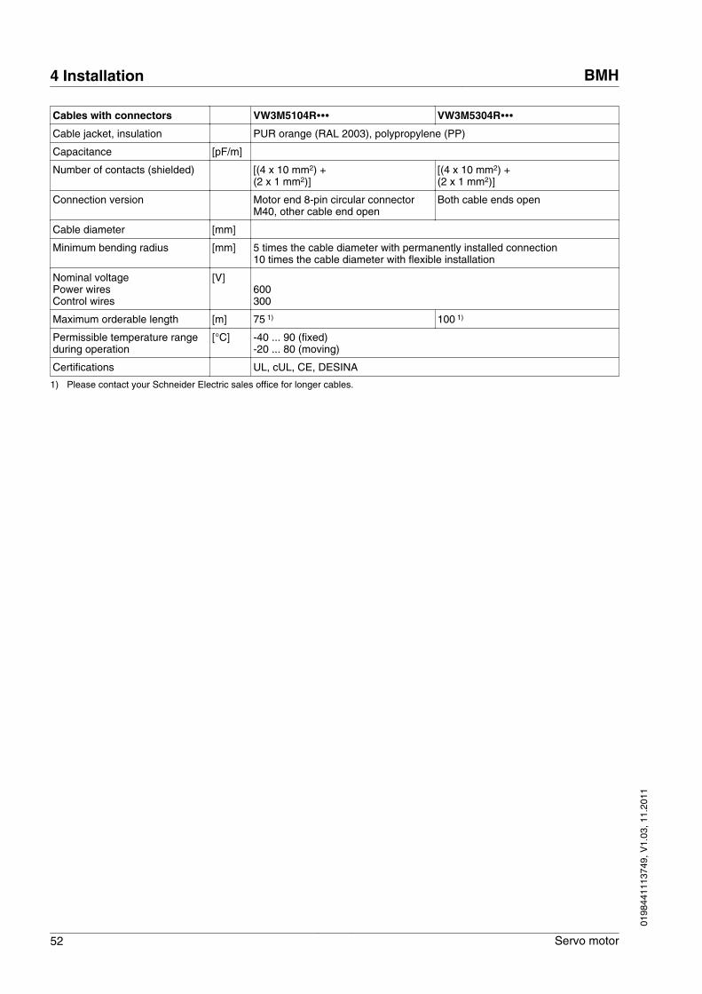
Cables with connectors VW3M5104R∙∙∙ VW3M5304R∙∙∙Cable jacket, insulation PUR orange (RAL 2003), polypropylene (PP)
Capacitance [pF/m]
Number of contacts (shielded) [(4 x 10 mm2) + (2 x 1 mm2)]
[(4 x 10 mm2) + (2 x 1 mm2)]
Connection version Motor end 8-pin circular connectorM40, other cable end open
Both cable ends open
Cable diameter [mm]
Minimum bending radius [mm] 5 times the cable diameter with permanently installed connection10 times the cable diameter with flexible installation
Nominal voltagePower wiresControl wires
[V]600300
Maximum orderable length [m] 75 1) 100 1)
Permissible temperature rangeduring operation
[°C] -40 ... 90 (fixed)-20 ... 80 (moving)
Certifications UL, cUL, CE, DESINA
1) Please contact your Schneider Electric sales office for longer cables.
4 Installation BMH
52 Servo motor
0198
4411
1374
9, V
1.03
, 11.
2011
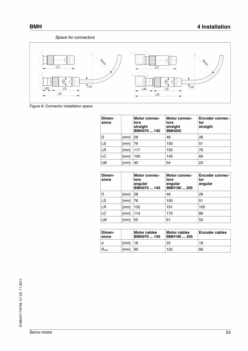
Space for connectors
LMLM LS
LR
LC
LS
LR
LC
∅D
∅D
Rmin
∅d
Rmin
∅d
Figure 8: Connector installation space
Dimen-sions
Motor connec-torsstraightBMH070 ... 140
Motor connec-torsstraightBMH205
Encoder connec-torstraight
D [mm] 28 46 26
LS [mm] 76 100 51
LR [mm] 117 155 76
LC [mm] 100 145 60
LM [mm] 40 54 23
Dimen-sions
Motor connec-torsangularBMH070 ... 140
Motor connec-torsangularBMH190 ... 205
Encoder connec-torangular
D [mm] 28 46 26
LS [mm] 76 100 51
LR [mm] 132 191 105
LC [mm] 114 170 89
LM [mm] 55 91 52
Dimen-sions
Motor cablesBMH070 ... 140
Motor cablesBMH190 ... 205
Encoder cables
d [mm] 18 25 18
Rmin [mm] 90 125 68
BMH 4 Installation
Servo motor 53
0198
4411
1374
9, V
1.03
, 11.
2011
4.4 Mounting the motor
WARNINGUNEXPECTED MOVEMENT CAUSED BY ELECTROSTATIC DIS-CHARGE
In rare cases, electrostatic discharge to the shaft may cause incor-rect operation of the encoder system and result in unexpected motormovements and damage to the bearing.
• Use conductive components (such as antistatic belts) or othersuitable measures to avoid static charge by motion.
Failure to follow these instructions can result in death, seriousinjury or equipment damage.
WARNINGUNEXPECTED MOVEMENT
If the permissible ambient conditions are exceeded, external sub-stances from the environment may penetrate and cause unexpectedmovement or equipment damage.
• Verify that the ambient conditions are met.• Do not allow seals to run dry.• Keep liquids from getting to the shaft bushing (for example in
mounting position IM V3).• Do not expose the shaft sealing rings and cable entries to the
direct spray of a pressure washer.
Failure to follow these instructions can result in death, seriousinjury or equipment damage.
WARNINGUNINTENDED BEHAVIOR CAUSED BY MECHANICAL DAMAGE TO THEMOTOR
If the maximum permissible forces at the shaft are exceeded, this willresult in premature wear of the bearing, shaft breakage or damage tothe encoder.
• Do not exceed the maximum permissible axial and radial forces.• Protect the shaft from impact.• Do not exceed the maximum permissible axial force when press-
ing on components.
Failure to follow these instructions can result in death, seriousinjury or equipment damage.
4 Installation BMH
54 Servo motor
0198
4411
1374
9, V
1.03
, 11.
2011
WARNINGHOT SURFACES
The heat sink at the product may heat up to over 100°C (212°F) dur-ing operation.
• Avoid contact with the hot heat sink.• Do not allow flammable or heat-sensitive parts in the immediate
vicinity.• Consider the measures for heat dissipation described.
Failure to follow these instructions can result in death or seri-ous injury.
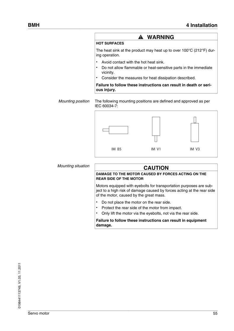
Mounting position The following mounting positions are defined and approved as perIEC 60034-7:
IM B5 IM V1 IM V3
Mounting situation CAUTIONDAMAGE TO THE MOTOR CAUSED BY FORCES ACTING ON THEREAR SIDE OF THE MOTOR
Motors equipped with eyebolts for transportation purposes are sub-ject to a high risk of damage caused by forces acting at the rear sideof the motor, caused by the great mass.
• Do not place the motor on the rear side.• Protect the rear side of the motor from impact.• Only lift the motor via the eyebolts, not via the rear side.
Failure to follow these instructions can result in equipmentdamage.
BMH 4 Installation
Servo motor 55
0198
4411
1374
9, V
1.03
, 11.
2011
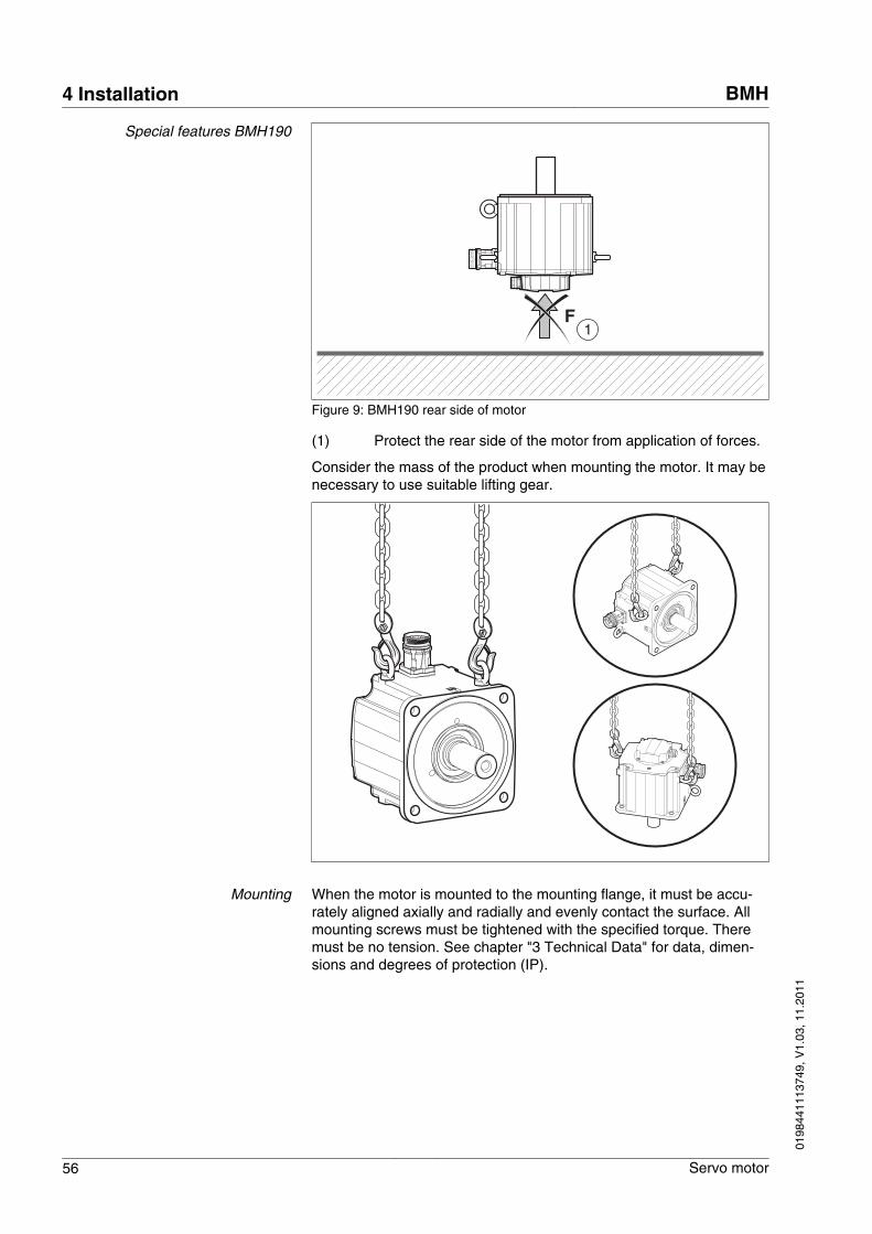
Special features BMH190
F1
Figure 9: BMH190 rear side of motor
(1) Protect the rear side of the motor from application of forces.
Consider the mass of the product when mounting the motor. It may benecessary to use suitable lifting gear.
Mounting When the motor is mounted to the mounting flange, it must be accu-rately aligned axially and radially and evenly contact the surface. Allmounting screws must be tightened with the specified torque. Theremust be no tension. See chapter "3 Technical Data" for data, dimen-sions and degrees of protection (IP).
4 Installation BMH
56 Servo motor
0198
4411
1374
9, V
1.03
, 11.
2011
Mounting output components If output components are not properly mounted, the motor may bedamaged. Output components such as pulleys, couplings must bemounted with suitable equipment and tools. The maximum axial andradial forces acting on the shaft must not exceed the maximum shaftload values specified, see "3.4.2 Shaft load".
Observe the mounting instructions provided by the manufacturer ofthe output component. Motor and output component must be accu-rately aligned both axially and radially. Failure to follow the instructionswill cause runout, damage to the rolling bearings and premature wear.
BMH 4 Installation
Servo motor 57
0198
4411
1374
9, V
1.03
, 11.
2011
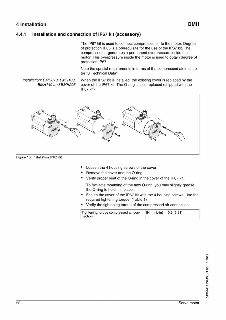
4.4.1 Installation and connection of IP67 kit (accessory)
The IP67 kit is used to connect compressed air to the motor. Degreeof protection IP65 is a prerequisite for the use of the IP67 kit. Thecompressed air generates a permanent overpressure inside themotor. This overpressure inside the motor is used to obtain degree ofprotection IP67.
Note the special requirements in terms of the compressed air in chap-ter "3 Technical Data".
Installation: BMH070, BMH100,BMH140 and BMH205
When the IP67 kit is installed, the existing cover is replaced by thecover of the IP67 kit. The O-ring is also replaced (shipped with theIP67 kit).
Figure 10: Installation IP67 Kit
▶ Loosen the 4 housing screws of the cover.▶ Remove the cover and the O-ring▶ Verify proper seat of the O-ring in the cover of the IP67 kit.
To facilitate mounting of the new O-ring, you may slightly greasethe O-ring to hold it in place.
▶ Fasten the cover of the IP67 kit with the 4 housing screws. Use therequired tightening torque. (Table 1)
▶ Verify the tightening torque of the compressed air connection:
Tightening torque compressed air con-nection
[Nm] (lb‧in) 0.6 (5.31)
4 Installation BMH
58 Servo motor
0198
4411
1374
9, V
1.03
, 11.
2011
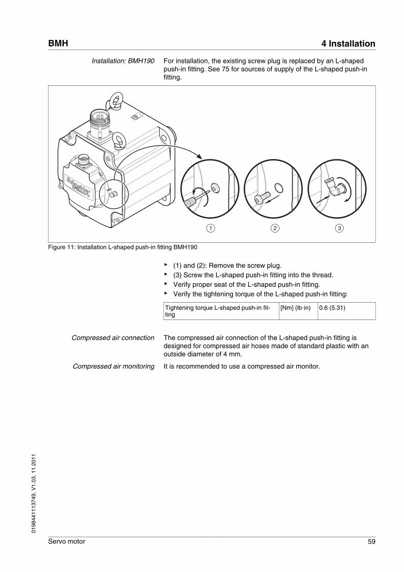
Installation: BMH190 For installation, the existing screw plug is replaced by an L-shapedpush-in fitting. See 75 for sources of supply of the L-shaped push-infitting.
1 2 3
Figure 11: Installation L-shaped push-in fitting BMH190
▶ (1) and (2): Remove the screw plug.▶ (3) Screw the L-shaped push-in fitting into the thread.▶ Verify proper seat of the L-shaped push-in fitting.▶ Verify the tightening torque of the L-shaped push-in fitting:
Tightening torque L-shaped push-in fit-ting
[Nm] (lb‧in) 0.6 (5.31)
Compressed air connection The compressed air connection of the L-shaped push-in fitting isdesigned for compressed air hoses made of standard plastic with anoutside diameter of 4 mm.
Compressed air monitoring It is recommended to use a compressed air monitor.
BMH 4 Installation
Servo motor 59
0198
4411
1374
9, V
1.03
, 11.
2011
4.5 Electrical installation
4.5.1 Connectors and connector assignments
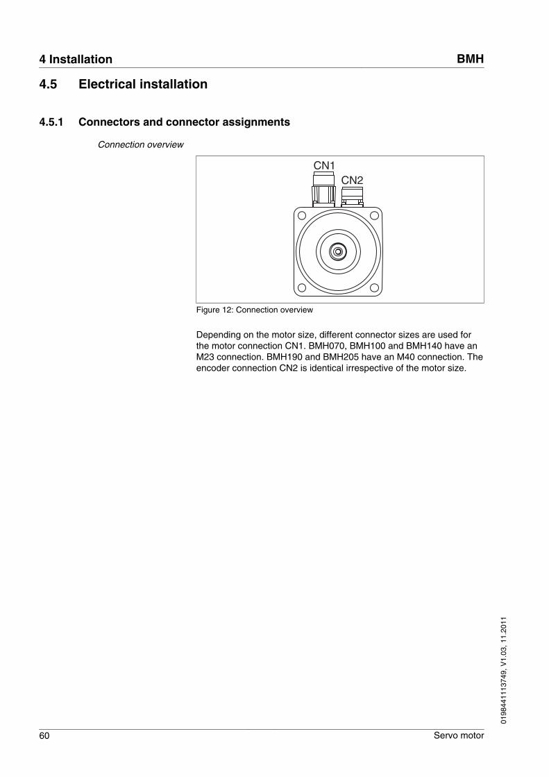
Connection overview
CN1CN2
Figure 12: Connection overview
Depending on the motor size, different connector sizes are used forthe motor connection CN1. BMH070, BMH100 and BMH140 have anM23 connection. BMH190 and BMH205 have an M40 connection. Theencoder connection CN2 is identical irrespective of the motor size.
4 Installation BMH
60 Servo motor
0198
4411
1374
9, V
1.03
, 11.
2011
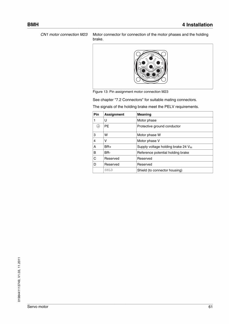
CN1 motor connection M23 Motor connector for connection of the motor phases and the holdingbrake.
3 14 A
BC
D
Figure 13: Pin assignment motor connection M23
See chapter "7.2 Connectors" for suitable mating connectors.
The signals of the holding brake meet the PELV requirements.
Pin Assignment Meaning
1 U Motor phase
PE Protective ground conductor
3 W Motor phase W
4 V Motor phase V
A BR+ Supply voltage holding brake 24 Vdc
B BR- Reference potential holding brake
C Reserved Reserved
D Reserved Reserved
SHLD Shield (to connector housing)
BMH 4 Installation
Servo motor 61
0198
4411
1374
9, V
1.03
, 11.
2011
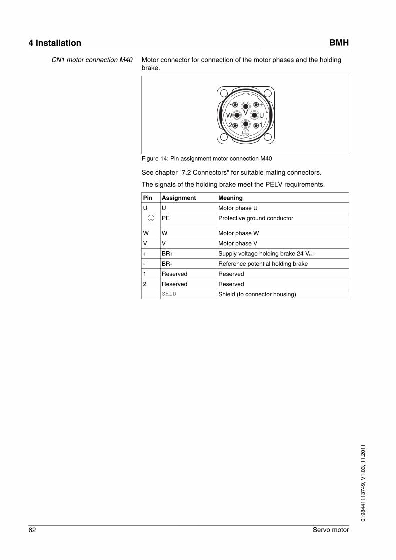
CN1 motor connection M40 Motor connector for connection of the motor phases and the holdingbrake.
12W V U
+-
Figure 14: Pin assignment motor connection M40
See chapter "7.2 Connectors" for suitable mating connectors.
The signals of the holding brake meet the PELV requirements.
Pin Assignment Meaning
U U Motor phase U
PE Protective ground conductor
W W Motor phase W
V V Motor phase V
+ BR+ Supply voltage holding brake 24 Vdc
- BR- Reference potential holding brake
1 Reserved Reserved
2 Reserved Reserved
SHLD Shield (to connector housing)
4 Installation BMH
62 Servo motor
0198
4411
1374
9, V
1.03
, 11.
2011
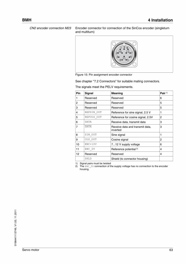
CN2 encoder connection M23 Encoder connector for connection of the SinCos encoder (singleturnand multiturn)
1 9
43
1026
5
7
812
11
Figure 15: Pin assignment encoder connector
See chapter "7.2 Connectors" for suitable mating connectors.
The signals meet the PELV requirements.
Pin Signal Meaning Pair 1)
1 Reserved Reserved 6
2 Reserved Reserved 5
3 Reserved Reserved 5
4 REFSIN_OUT Reference for sine signal, 2.5 V 1
5 REFCOS_OUT Reference for cosine signal, 2.5V 2
6 DATA Receive data, transmit data 3
7 DATA Receive data and transmit data,inverted
3
8 SIN_OUT Sine signal 1
9 COS_OUT Cosine signal 2
10 ENC+10V 7...12 V supply voltage 6
11 ENC_0V Reference potential 2) 4
12 Reserved Reserved 4
SHLD Shield (to connector housing)
1) Signal pairs must be twisted2) The ENC_0V connection of the supply voltage has no connection to the encoder
housing.
BMH 4 Installation
Servo motor 63
0198
4411
1374
9, V
1.03
, 11.
2011
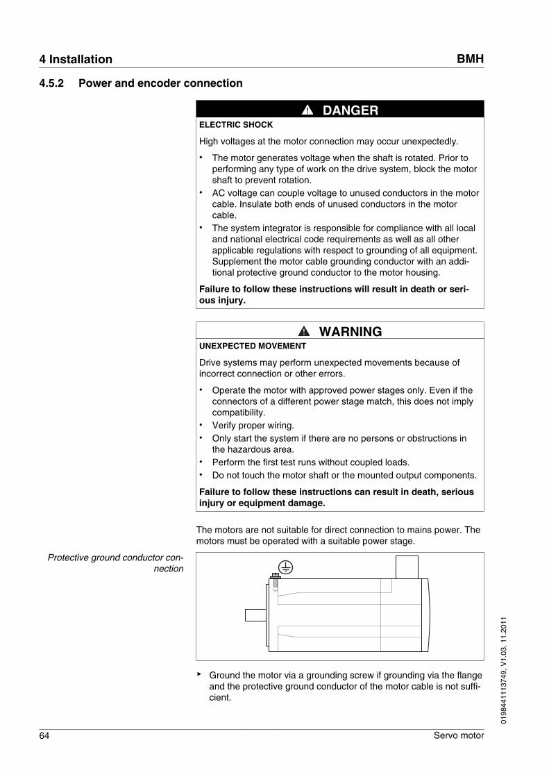
4.5.2 Power and encoder connection
DANGERELECTRIC SHOCK
High voltages at the motor connection may occur unexpectedly.
• The motor generates voltage when the shaft is rotated. Prior toperforming any type of work on the drive system, block the motorshaft to prevent rotation.
• AC voltage can couple voltage to unused conductors in the motorcable. Insulate both ends of unused conductors in the motorcable.
• The system integrator is responsible for compliance with all localand national electrical code requirements as well as all otherapplicable regulations with respect to grounding of all equipment.Supplement the motor cable grounding conductor with an addi-tional protective ground conductor to the motor housing.
Failure to follow these instructions will result in death or seri-ous injury.
WARNINGUNEXPECTED MOVEMENT
Drive systems may perform unexpected movements because ofincorrect connection or other errors.
• Operate the motor with approved power stages only. Even if theconnectors of a different power stage match, this does not implycompatibility.
• Verify proper wiring.• Only start the system if there are no persons or obstructions in
the hazardous area.• Perform the first test runs without coupled loads.• Do not touch the motor shaft or the mounted output components.
Failure to follow these instructions can result in death, seriousinjury or equipment damage.
The motors are not suitable for direct connection to mains power. Themotors must be operated with a suitable power stage.
Protective ground conductor con-nection
▶ Ground the motor via a grounding screw if grounding via the flangeand the protective ground conductor of the motor cable is not suffi-cient.
4 Installation BMH
64 Servo motor
0198
4411
1374
9, V
1.03
, 11.
2011
Note the required tightening torque and the property class of thegrounding screw, see Table 1 in chapter 21.
Motor and encoder system connectors must not be disconnected orreconnected as long as voltage is present.
Assembling cables Insulate unused wires individually.
▶ Note the EMC requirements for motor cables and encoder cables,page 48.
▶ Use equipotential bonding conductors for equipotential bonding.
Follow the procedure and note the dimensions in Figure 18.
Depending on the motor size, different connector sizes are used forthe motor connection CN1. BMH070, BMH100 and BMH140 have anM23 connection. BMH190 and BMH205 have an M40 connection. Theencoder connection CN2 is identical irrespective of the motor size.
BMH 4 Installation
Servo motor 65
0198
4411
1374
9, V
1.03
, 11.
2011
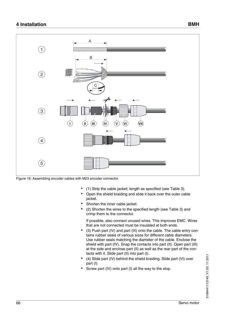
A
B
C
1
3
4
2
5
II VIIII VIIVIIV
Figure 16: Assembling encoder cables with M23 encoder connector
▶ (1) Strip the cable jacket; length as specified (see Table 3).▶ Open the shield braiding and slide it back over the outer cable
jacket.▶ Shorten the inner cable jacket.▶ (2) Shorten the wires to the specified length (see Table 3) and
crimp them to the connector.
If possible, also connect unused wires. This improves EMC. Wiresthat are not connected must be insulated at both ends.
▶ (3) Push part (IV) and part (III) onto the cable. The cable entry con-tains rubber seals of various sizes for different cable diameters.Use rubber seals matching the diameter of the cable. Enclose theshield with part (IV). Snap the contacts into part (II). Open part (III)at the side and enclose part (II) as well as the rear part of the con-tacts with it. Slide part (II) into part (I).
▶ (4) Slide part (IV) behind the shield braiding. Slide part (VI) overpart (I).
▶ Screw part (IV) onto part (I) all the way to the stop.
4 Installation BMH
66 Servo motor
0198
4411
1374
9, V
1.03
, 11.
2011
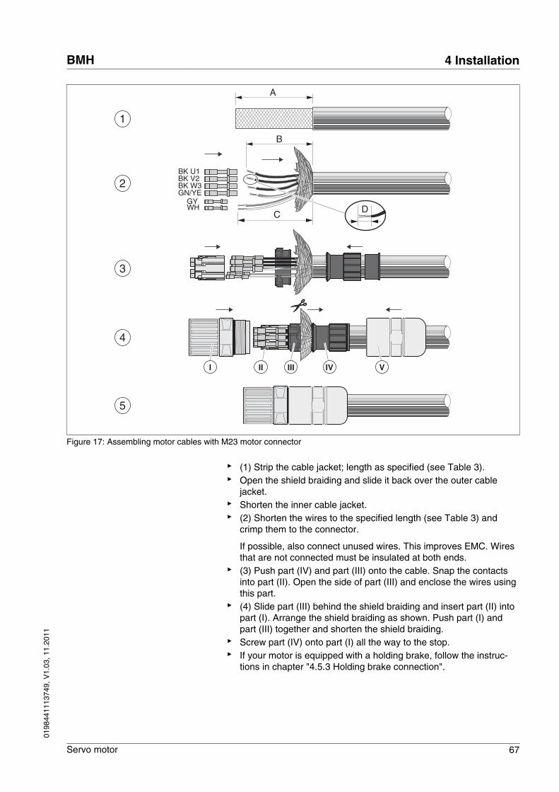
1
3
A
4
2
5
BK U1BK V2BK W3GN/YE
WHGY
C
B
D
II VIVIIII
Figure 17: Assembling motor cables with M23 motor connector
▶ (1) Strip the cable jacket; length as specified (see Table 3).▶ Open the shield braiding and slide it back over the outer cable
jacket.▶ Shorten the inner cable jacket.▶ (2) Shorten the wires to the specified length (see Table 3) and
crimp them to the connector.
If possible, also connect unused wires. This improves EMC. Wiresthat are not connected must be insulated at both ends.
▶ (3) Push part (IV) and part (III) onto the cable. Snap the contactsinto part (II). Open the side of part (III) and enclose the wires usingthis part.
▶ (4) Slide part (III) behind the shield braiding and insert part (II) intopart (I). Arrange the shield braiding as shown. Push part (I) andpart (III) together and shorten the shield braiding.
▶ Screw part (IV) onto part (I) all the way to the stop.▶ If your motor is equipped with a holding brake, follow the instruc-
tions in chapter "4.5.3 Holding brake connection".
BMH 4 Installation
Servo motor 67
0198
4411
1374
9, V
1.03
, 11.
2011
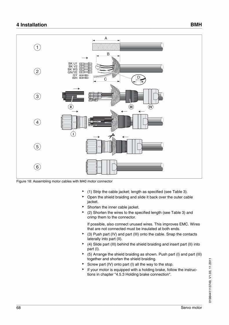
1
3
4
2
5
BK U1BK V2BK W3GN/YE
WHGY
C
A
6
B
D
II
I
IVIII
Figure 18: Assembling motor cables with M40 motor connector
▶ (1) Strip the cable jacket; length as specified (see Table 3).▶ Open the shield braiding and slide it back over the outer cable
jacket.▶ Shorten the inner cable jacket.▶ (2) Shorten the wires to the specified length (see Table 3) and
crimp them to the connector.
If possible, also connect unused wires. This improves EMC. Wiresthat are not connected must be insulated at both ends.
▶ (3) Push part (IV) and part (III) onto the cable. Snap the contactslaterally into part (II).
▶ (4) Slide part (III) behind the shield braiding and insert part (II) intopart (I).
▶ (5) Arrange the shield braiding as shown. Push part (I) and part (III)together and shorten the shield braiding.
▶ Screw part (IV) onto part (I) all the way to the stop.▶ If your motor is equipped with a holding brake, follow the instruc-
tions in chapter "4.5.3 Holding brake connection".
4 Installation BMH
68 Servo motor
0198
4411
1374
9, V
1.03
, 11.
2011
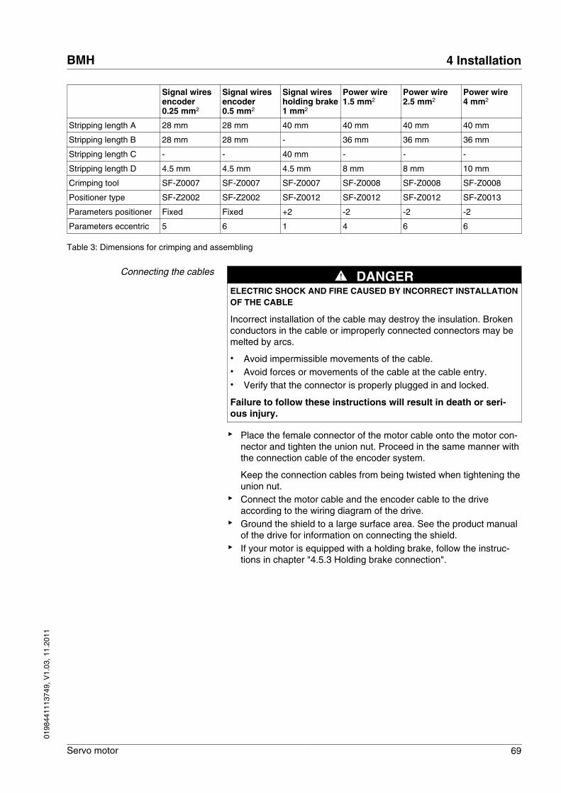
Signal wiresencoder0.25 mm2
Signal wiresencoder0.5 mm2
Signal wiresholding brake1 mm2
Power wire1.5 mm2
Power wire2.5 mm2
Power wire4 mm2
Stripping length A 28 mm 28 mm 40 mm 40 mm 40 mm 40 mm
Stripping length B 28 mm 28 mm - 36 mm 36 mm 36 mm
Stripping length C - - 40 mm - - -
Stripping length D 4.5 mm 4.5 mm 4.5 mm 8 mm 8 mm 10 mm
Crimping tool SF-Z0007 SF-Z0007 SF-Z0007 SF-Z0008 SF-Z0008 SF-Z0008
Positioner type SF-Z2002 SF-Z2002 SF-Z0012 SF-Z0012 SF-Z0012 SF-Z0013
Parameters positioner Fixed Fixed +2 -2 -2 -2
Parameters eccentric 5 6 1 4 6 6
Table 3: Dimensions for crimping and assembling
Connecting the cables DANGERELECTRIC SHOCK AND FIRE CAUSED BY INCORRECT INSTALLATIONOF THE CABLE
Incorrect installation of the cable may destroy the insulation. Brokenconductors in the cable or improperly connected connectors may bemelted by arcs.
• Avoid impermissible movements of the cable.• Avoid forces or movements of the cable at the cable entry.• Verify that the connector is properly plugged in and locked.
Failure to follow these instructions will result in death or seri-ous injury.
▶ Place the female connector of the motor cable onto the motor con-nector and tighten the union nut. Proceed in the same manner withthe connection cable of the encoder system.
Keep the connection cables from being twisted when tightening theunion nut.
▶ Connect the motor cable and the encoder cable to the driveaccording to the wiring diagram of the drive.
▶ Ground the shield to a large surface area. See the product manualof the drive for information on connecting the shield.
▶ If your motor is equipped with a holding brake, follow the instruc-tions in chapter "4.5.3 Holding brake connection".
BMH 4 Installation
Servo motor 69
0198
4411
1374
9, V
1.03
, 11.
2011
4.5.3 Holding brake connection
WARNINGLOSS OF BRAKING FORCE DUE TO WEAR OR HIGH TEMPERATURE
Applying the holding brake while the motor is running will causeexcessive wear and loss of the braking force.
• Do not use the brake as a service brake.• Note that a emergency stop may also cause wear.• Note the maximum number of brake applications and the kinetic
energy during braking of moving loads.
Failure to follow these instructions can result in death, seriousinjury or equipment damage.
WARNINGUNEXPECTED MOVEMENT
Releasing the holding brake may cause an unexpected movement inthe system, for example if vertical axes are used.
• Take appropriate measures to avoid damage caused by falling orlowering loads.
• Only run the test if there are no persons or obstacles in the haz-ardous area.
Failure to follow these instructions can result in death, seriousinjury or equipment damage.
CAUTIONMISOPERATION OF THE HOLDING BRAKE CAUSED BY INCORRECTVOLTAGE
If the voltage is incorrect, the holding brake cannot be releasedwhich causes wear.
• Note that if the voltage is higher than the specified value, theholding brake may be re-applied.
• Note that if the voltage polarity is incorrect, the holding brake can-not be released.
• Note the voltage drop in the cable according to the conductorcross section.
• Verify that the specified voltage is available at the holding brakeconnection.
Failure to follow these instructions can result in injury or equip-ment damage.
A motor with a holding brake requires a suitable holding brake control-ler which releases the brake when the rotary movement starts andlocks the motor shaft when the motor is stopped.
Cable specifications • Minimum wire cross section: 2 * 1.0 mm2 (AWG 16)• Maximum cable length: See product manual of the drive.
4 Installation BMH
70 Servo motor
0198
4411
1374
9, V
1.03
, 11.
2011
5 Commissioning
5
WARNINGUNEXPECTED MOVEMENT
Drive systems may perform unexpected movements because ofincorrect connection or other errors.
• Operate the motor with approved power stages only. Even if theconnectors of a different power stage match, this does not implycompatibility.
• Verify proper wiring.• Only start the system if there are no persons or obstructions in
the hazardous area.• Perform the first test runs without coupled loads.• Do not touch the motor shaft or the mounted output components.
Failure to follow these instructions can result in death, seriousinjury or equipment damage.
WARNINGROTATING PARTS
Rotating parts may cause injuries and may catch clothing or hair.Loose parts or parts that are out of balance may be catapulted away.
• Verify correct mounting and installation of all rotating parts.• Use a cover to help protect against rotating parts.
Failure to follow these instructions can result in death, seriousinjury or equipment damage.
WARNINGFALLING PARTS
The motor may move, tip and crash down as a result of the reactiontorque.
• Mount the motor securely so it will not break loose during strongacceleration.
Failure to follow these instructions can result in death, seriousinjury or equipment damage.
BMH 5 Commissioning
Servo motor 71
0198
4411
1374
9, V
1.03
, 11.
2011
WARNINGHOT SURFACES
The heat sink at the product may heat up to over 100°C (212°F) dur-ing operation.
• Avoid contact with the hot heat sink.• Do not allow flammable or heat-sensitive parts in the immediate
vicinity.• Consider the measures for heat dissipation described.
Failure to follow these instructions can result in death or seri-ous injury.
Checking the installation The installation must be checked prior to commissioning.
▶ Check the mechanical installation.▶ Check the electrical installation.
• Did you connect all protective ground conductors?• Did you properly connect and install all cables and connectors?• Did you tighten the cable glands properly?
▶ Check the ambient conditions.
• Does the installation meet the ambient conditions specified?
▶ Check the output components.
• Have the installed output components been balanced and accu-rately aligned?
▶ Check the parallel key at the shaft end of the motor.
If you have a motor with a parallel key groove and parallel key, theparallel key must not be inserted during commissioning withoutoutput component or it must be appropriately secured.
▶ Verify the function of the holding brake.
• Is the holding brake able to hold the maximum acting load?• Is the holding brake is released before a start?
Observe the information on commissioning in the product manual ofthe drive.
5 Commissioning BMH
72 Servo motor
0198
4411
1374
9, V
1.03
, 11.
2011
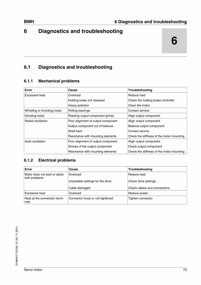
6 Diagnostics and troubleshooting
6
6.1 Diagnostics and troubleshooting
6.1.1 Mechanical problems
Error Cause Troubleshooting
Excessive heat Overload
Holding brake not released
Heavy pollution
Reduce load
Check the holding brake controller
Clean the motor
Whistling or knocking noise Rolling bearings Contact service
Grinding noise Rotating output component grinds Align output component
Radial oscillation Poor alignment of output component
Output component out of balance
Shaft bent
Resonance with mounting elements
Align output component
Balance output component
Contact service
Check the stiffness of the motor mounting
Axial oscillation Poor alignment of output component
Shocks of the output component
Resonance with mounting elements
Align output component
Check output component
Check the stiffness of the motor mounting
6.1.2 Electrical problems
Error Cause Troubleshooting
Motor does not start or startswith problems
Overload
Unsuitable settings for the drive
Cable damaged
Reduce load
Check drive settings
Check cables and connections
Excessive heat Overload Reduce power
Heat at the connection termi-nals
Connector loose or not tightened Tighten connector
BMH 6 Diagnostics and troubleshooting
Servo motor 73
0198
4411
1374
9, V
1.03
, 11.
2011
6 Diagnostics and troubleshooting BMH
74 Servo motor
0198
4411
1374
9, V
1.03
, 11.
2011
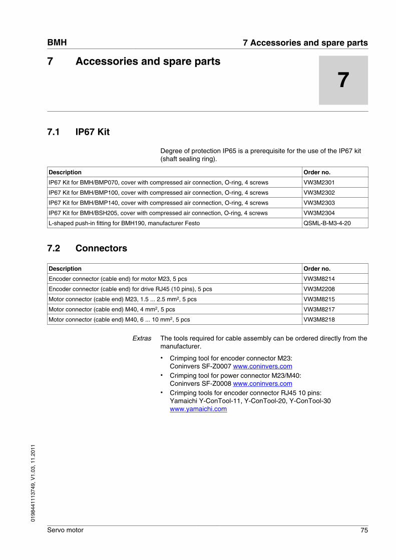
7 Accessories and spare parts
7
7.1 IP67 Kit
Degree of protection IP65 is a prerequisite for the use of the IP67 kit(shaft sealing ring).
Description Order no.
IP67 Kit for BMH/BMP070, cover with compressed air connection, O-ring, 4 screws VW3M2301
IP67 Kit for BMH/BMP100, cover with compressed air connection, O-ring, 4 screws VW3M2302
IP67 Kit for BMH/BMP140, cover with compressed air connection, O-ring, 4 screws VW3M2303
IP67 Kit for BMH/BSH205, cover with compressed air connection, O-ring, 4 screws VW3M2304
L-shaped push-in fitting for BMH190, manufacturer Festo QSML-B-M3-4-20
7.2 Connectors
Description Order no.
Encoder connector (cable end) for motor M23, 5 pcs VW3M8214
Encoder connector (cable end) for drive RJ45 (10 pins), 5 pcs VW3M2208
Motor connector (cable end) M23, 1.5 ... 2.5 mm2, 5 pcs VW3M8215
Motor connector (cable end) M40, 4 mm2, 5 pcs VW3M8217
Motor connector (cable end) M40, 6 ... 10 mm2, 5 pcs VW3M8218
Extras The tools required for cable assembly can be ordered directly from themanufacturer.
• Crimping tool for encoder connector M23:Coninvers SF-Z0007 www.coninvers.com
• Crimping tool for power connector M23/M40:Coninvers SF-Z0008 www.coninvers.com
• Crimping tools for encoder connector RJ45 10 pins:Yamaichi Y-ConTool-11, Y-ConTool-20, Y-ConTool-30www.yamaichi.com
BMH 7 Accessories and spare parts
Servo motor 75
0198
4411
1374
9, V
1.03
, 11.
2011
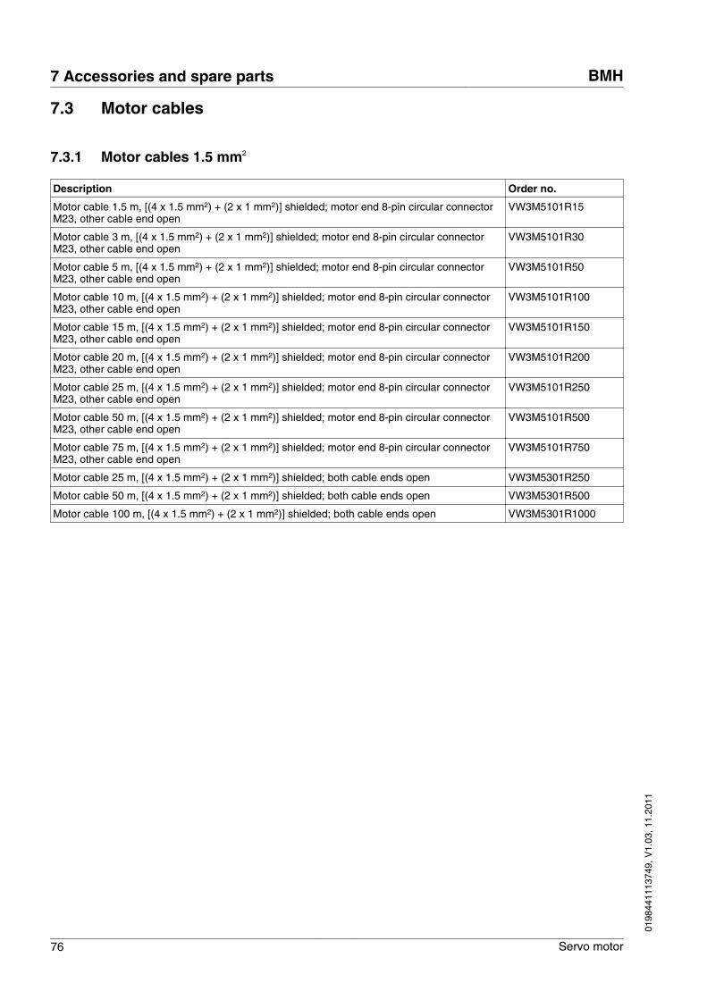
7.3 Motor cables
7.3.1 Motor cables 1.5 mm2
Description Order no.
Motor cable 1.5 m, [(4 x 1.5 mm2) + (2 x 1 mm2)] shielded; motor end 8-pin circular connectorM23, other cable end open
VW3M5101R15
Motor cable 3 m, [(4 x 1.5 mm2) + (2 x 1 mm2)] shielded; motor end 8-pin circular connectorM23, other cable end open
VW3M5101R30
Motor cable 5 m, [(4 x 1.5 mm2) + (2 x 1 mm2)] shielded; motor end 8-pin circular connectorM23, other cable end open
VW3M5101R50
Motor cable 10 m, [(4 x 1.5 mm2) + (2 x 1 mm2)] shielded; motor end 8-pin circular connectorM23, other cable end open
VW3M5101R100
Motor cable 15 m, [(4 x 1.5 mm2) + (2 x 1 mm2)] shielded; motor end 8-pin circular connectorM23, other cable end open
VW3M5101R150
Motor cable 20 m, [(4 x 1.5 mm2) + (2 x 1 mm2)] shielded; motor end 8-pin circular connectorM23, other cable end open
VW3M5101R200
Motor cable 25 m, [(4 x 1.5 mm2) + (2 x 1 mm2)] shielded; motor end 8-pin circular connectorM23, other cable end open
VW3M5101R250
Motor cable 50 m, [(4 x 1.5 mm2) + (2 x 1 mm2)] shielded; motor end 8-pin circular connectorM23, other cable end open
VW3M5101R500
Motor cable 75 m, [(4 x 1.5 mm2) + (2 x 1 mm2)] shielded; motor end 8-pin circular connectorM23, other cable end open
VW3M5101R750
Motor cable 25 m, [(4 x 1.5 mm2) + (2 x 1 mm2)] shielded; both cable ends open VW3M5301R250
Motor cable 50 m, [(4 x 1.5 mm2) + (2 x 1 mm2)] shielded; both cable ends open VW3M5301R500
Motor cable 100 m, [(4 x 1.5 mm2) + (2 x 1 mm2)] shielded; both cable ends open VW3M5301R1000
7 Accessories and spare parts BMH
76 Servo motor
0198
4411
1374
9, V
1.03
, 11.
2011
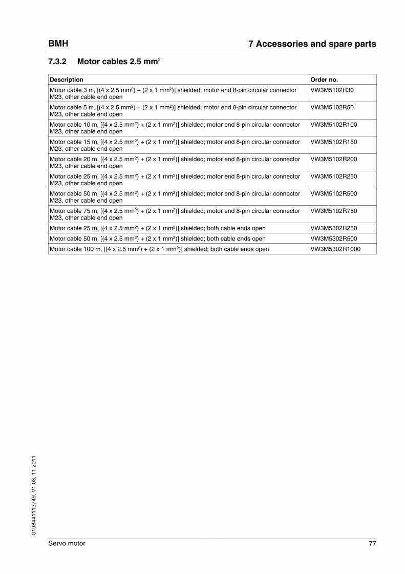
7.3.2 Motor cables 2.5 mm2
Description Order no.
Motor cable 3 m, [(4 x 2.5 mm2) + (2 x 1 mm2)] shielded; motor end 8-pin circular connectorM23, other cable end open
VW3M5102R30
Motor cable 5 m, [(4 x 2.5 mm2) + (2 x 1 mm2)] shielded; motor end 8-pin circular connectorM23, other cable end open
VW3M5102R50
Motor cable 10 m, [(4 x 2.5 mm2) + (2 x 1 mm2)] shielded; motor end 8-pin circular connectorM23, other cable end open
VW3M5102R100
Motor cable 15 m, [(4 x 2.5 mm2) + (2 x 1 mm2)] shielded; motor end 8-pin circular connectorM23, other cable end open
VW3M5102R150
Motor cable 20 m, [(4 x 2.5 mm2) + (2 x 1 mm2)] shielded; motor end 8-pin circular connectorM23, other cable end open
VW3M5102R200
Motor cable 25 m, [(4 x 2.5 mm2) + (2 x 1 mm2)] shielded; motor end 8-pin circular connectorM23, other cable end open
VW3M5102R250
Motor cable 50 m, [(4 x 2.5 mm2) + (2 x 1 mm2)] shielded; motor end 8-pin circular connectorM23, other cable end open
VW3M5102R500
Motor cable 75 m, [(4 x 2.5 mm2) + (2 x 1 mm2)] shielded; motor end 8-pin circular connectorM23, other cable end open
VW3M5102R750
Motor cable 25 m, [(4 x 2.5 mm2) + (2 x 1 mm2)] shielded; both cable ends open VW3M5302R250
Motor cable 50 m, [(4 x 2.5 mm2) + (2 x 1 mm2)] shielded; both cable ends open VW3M5302R500
Motor cable 100 m, [(4 x 2.5 mm2) + (2 x 1 mm2)] shielded; both cable ends open VW3M5302R1000
BMH 7 Accessories and spare parts
Servo motor 77
0198
4411
1374
9, V
1.03
, 11.
2011
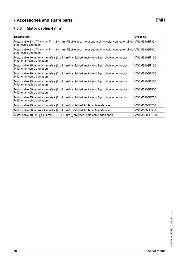
7.3.3 Motor cables 4 mm2
Description Order no.
Motor cable 3 m, [(4 x 4 mm2) + (2 x 1 mm2)] shielded; motor end 8-pin circular connector M40,other cable end open
VW3M5103R30
Motor cable 5 m, [(4 x 4 mm2) + (2 x 1 mm2)] shielded; motor end 8-pin circular connector M40,other cable end open
VW3M5103R50
Motor cable 10 m, [(4 x 4 mm2) + (2 x 1 mm2)] shielded; motor end 8-pin circular connectorM40, other cable end open
VW3M5103R100
Motor cable 15 m, [(4 x 4 mm2) + (2 x 1 mm2)] shielded; motor end 8-pin circular connectorM40, other cable end open
VW3M5103R150
Motor cable 20 m, [(4 x 4 mm2) + (2 x 1 mm2)] shielded; motor end 8-pin circular connectorM40, other cable end open
VW3M5103R200
Motor cable 25 m, [(4 x 4 mm2) + (2 x 1 mm2)] shielded; motor end 8-pin circular connectorM40, other cable end open
VW3M5103R250
Motor cable 50 m, [(4 x 4 mm2) + (2 x 1 mm2)] shielded; motor end 8-pin circular connectorM40, other cable end open
VW3M5103R500
Motor cable 75 m, [(4 x 4 mm2) + (2 x 1 mm2)] shielded; motor end 8-pin circular connectorM40, other cable end open
VW3M5103R750
Motor cable 25 m, [(4 x 4 mm2) + (2 x 1 mm2)] shielded; both cable ends open VW3M5303R250
Motor cable 50 m, [(4 x 4 mm2) + (2 x 1 mm2)] shielded; both cable ends open VW3M5303R500
Motor cable 100 m, [(4 x 4 mm2) + (2 x 1 mm2)] shielded; both cable ends open VW3M5303R1000
7 Accessories and spare parts BMH
78 Servo motor
0198
4411
1374
9, V
1.03
, 11.
2011
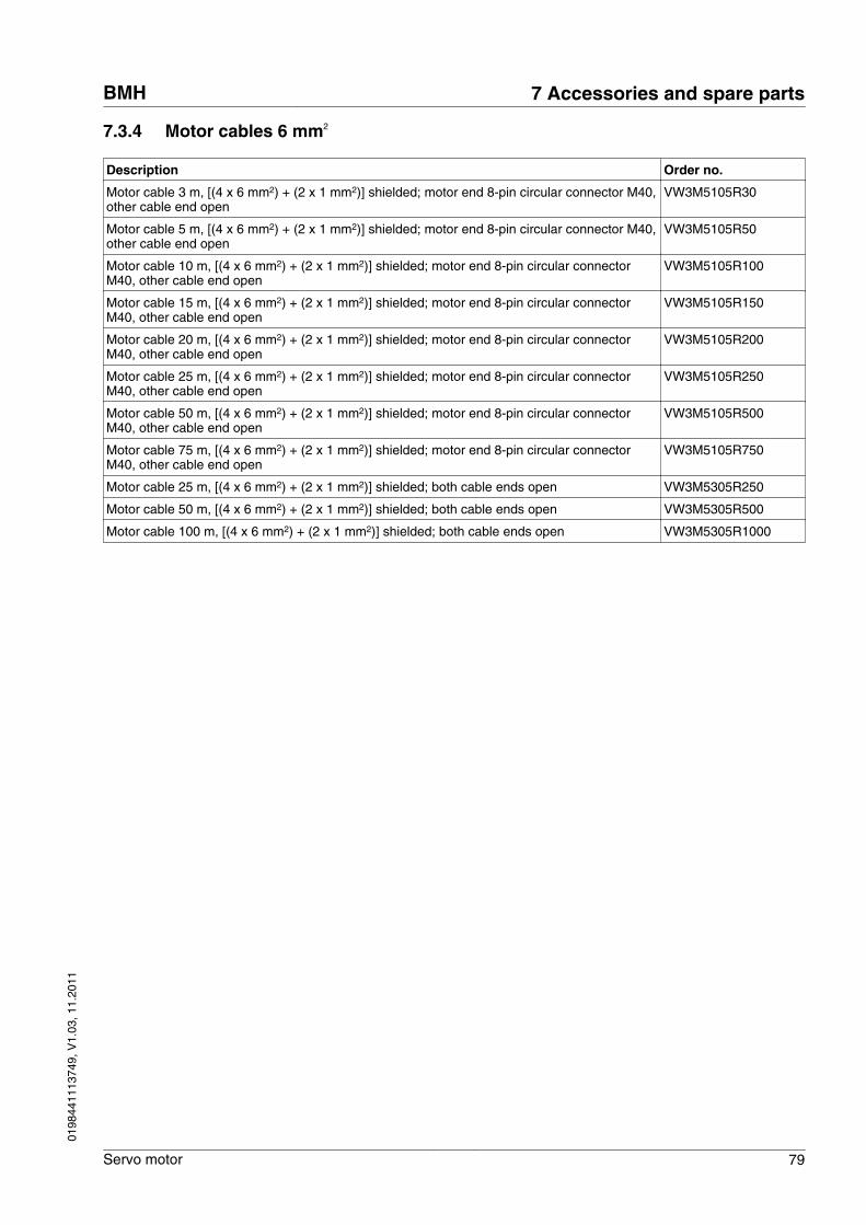
7.3.4 Motor cables 6 mm2
Description Order no.
Motor cable 3 m, [(4 x 6 mm2) + (2 x 1 mm2)] shielded; motor end 8-pin circular connector M40,other cable end open
VW3M5105R30
Motor cable 5 m, [(4 x 6 mm2) + (2 x 1 mm2)] shielded; motor end 8-pin circular connector M40,other cable end open
VW3M5105R50
Motor cable 10 m, [(4 x 6 mm2) + (2 x 1 mm2)] shielded; motor end 8-pin circular connectorM40, other cable end open
VW3M5105R100
Motor cable 15 m, [(4 x 6 mm2) + (2 x 1 mm2)] shielded; motor end 8-pin circular connectorM40, other cable end open
VW3M5105R150
Motor cable 20 m, [(4 x 6 mm2) + (2 x 1 mm2)] shielded; motor end 8-pin circular connectorM40, other cable end open
VW3M5105R200
Motor cable 25 m, [(4 x 6 mm2) + (2 x 1 mm2)] shielded; motor end 8-pin circular connectorM40, other cable end open
VW3M5105R250
Motor cable 50 m, [(4 x 6 mm2) + (2 x 1 mm2)] shielded; motor end 8-pin circular connectorM40, other cable end open
VW3M5105R500
Motor cable 75 m, [(4 x 6 mm2) + (2 x 1 mm2)] shielded; motor end 8-pin circular connectorM40, other cable end open
VW3M5105R750
Motor cable 25 m, [(4 x 6 mm2) + (2 x 1 mm2)] shielded; both cable ends open VW3M5305R250
Motor cable 50 m, [(4 x 6 mm2) + (2 x 1 mm2)] shielded; both cable ends open VW3M5305R500
Motor cable 100 m, [(4 x 6 mm2) + (2 x 1 mm2)] shielded; both cable ends open VW3M5305R1000
BMH 7 Accessories and spare parts
Servo motor 79
0198
4411
1374
9, V
1.03
, 11.
2011
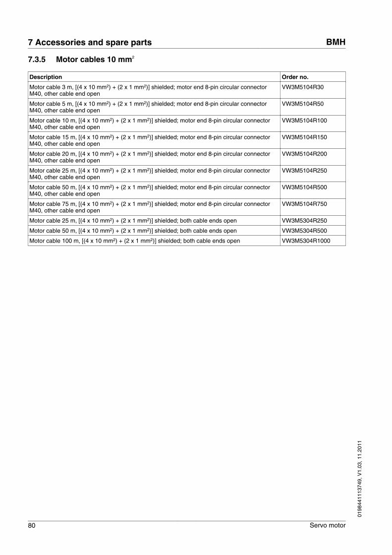
7.3.5 Motor cables 10 mm2
Description Order no.
Motor cable 3 m, [(4 x 10 mm2) + (2 x 1 mm2)] shielded; motor end 8-pin circular connectorM40, other cable end open
VW3M5104R30
Motor cable 5 m, [(4 x 10 mm2) + (2 x 1 mm2)] shielded; motor end 8-pin circular connectorM40, other cable end open
VW3M5104R50
Motor cable 10 m, [(4 x 10 mm2) + (2 x 1 mm2)] shielded; motor end 8-pin circular connectorM40, other cable end open
VW3M5104R100
Motor cable 15 m, [(4 x 10 mm2) + (2 x 1 mm2)] shielded; motor end 8-pin circular connectorM40, other cable end open
VW3M5104R150
Motor cable 20 m, [(4 x 10 mm2) + (2 x 1 mm2)] shielded; motor end 8-pin circular connectorM40, other cable end open
VW3M5104R200
Motor cable 25 m, [(4 x 10 mm2) + (2 x 1 mm2)] shielded; motor end 8-pin circular connectorM40, other cable end open
VW3M5104R250
Motor cable 50 m, [(4 x 10 mm2) + (2 x 1 mm2)] shielded; motor end 8-pin circular connectorM40, other cable end open
VW3M5104R500
Motor cable 75 m, [(4 x 10 mm2) + (2 x 1 mm2)] shielded; motor end 8-pin circular connectorM40, other cable end open
VW3M5104R750
Motor cable 25 m, [(4 x 10 mm2) + (2 x 1 mm2)] shielded; both cable ends open VW3M5304R250
Motor cable 50 m, [(4 x 10 mm2) + (2 x 1 mm2)] shielded; both cable ends open VW3M5304R500
Motor cable 100 m, [(4 x 10 mm2) + (2 x 1 mm2)] shielded; both cable ends open VW3M5304R1000
7 Accessories and spare parts BMH
80 Servo motor
0198
4411
1374
9, V
1.03
, 11.
2011
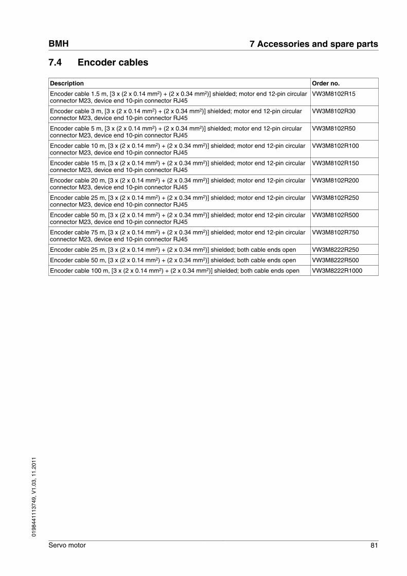
7.4 Encoder cables
Description Order no.
Encoder cable 1.5 m, [3 x (2 x 0.14 mm2) + (2 x 0.34 mm2)] shielded; motor end 12-pin circularconnector M23, device end 10-pin connector RJ45
VW3M8102R15
Encoder cable 3 m, [3 x (2 x 0.14 mm2) + (2 x 0.34 mm2)] shielded; motor end 12-pin circularconnector M23, device end 10-pin connector RJ45
VW3M8102R30
Encoder cable 5 m, [3 x (2 x 0.14 mm2) + (2 x 0.34 mm2)] shielded; motor end 12-pin circularconnector M23, device end 10-pin connector RJ45
VW3M8102R50
Encoder cable 10 m, [3 x (2 x 0.14 mm2) + (2 x 0.34 mm2)] shielded; motor end 12-pin circularconnector M23, device end 10-pin connector RJ45
VW3M8102R100
Encoder cable 15 m, [3 x (2 x 0.14 mm2) + (2 x 0.34 mm2)] shielded; motor end 12-pin circularconnector M23, device end 10-pin connector RJ45
VW3M8102R150
Encoder cable 20 m, [3 x (2 x 0.14 mm2) + (2 x 0.34 mm2)] shielded; motor end 12-pin circularconnector M23, device end 10-pin connector RJ45
VW3M8102R200
Encoder cable 25 m, [3 x (2 x 0.14 mm2) + (2 x 0.34 mm2)] shielded; motor end 12-pin circularconnector M23, device end 10-pin connector RJ45
VW3M8102R250
Encoder cable 50 m, [3 x (2 x 0.14 mm2) + (2 x 0.34 mm2)] shielded; motor end 12-pin circularconnector M23, device end 10-pin connector RJ45
VW3M8102R500
Encoder cable 75 m, [3 x (2 x 0.14 mm2) + (2 x 0.34 mm2)] shielded; motor end 12-pin circularconnector M23, device end 10-pin connector RJ45
VW3M8102R750
Encoder cable 25 m, [3 x (2 x 0.14 mm2) + (2 x 0.34 mm2)] shielded; both cable ends open VW3M8222R250
Encoder cable 50 m, [3 x (2 x 0.14 mm2) + (2 x 0.34 mm2)] shielded; both cable ends open VW3M8222R500
Encoder cable 100 m, [3 x (2 x 0.14 mm2) + (2 x 0.34 mm2)] shielded; both cable ends open VW3M8222R1000
BMH 7 Accessories and spare parts
Servo motor 81
0198
4411
1374
9, V
1.03
, 11.
2011
7 Accessories and spare parts BMH
82 Servo motor
0198
4411
1374
9, V
1.03
, 11.
2011
8 Service, maintenance and disposal
8
8.1 Service address
If you have any questions please contact your sales office. Your salesoffice staff will be happy to give you the name of a customer serviceoffice in your area.
http://www.schneider-electric.com
8.2 Storage
The motors must be transported and stored in a dry, dust-free andvibration-free environment. The ambient conditions and applicationconditions specified in chapter "3.1 General features" must be met; incase of doubt you must air-condition the storage location.
The storage time is primarily determined by the service life of the lubri-cants; do not store the product for more than 36 months. It is recom-mended to periodically operate the drive solution to maintain its opera-bility.
8.3 Maintenance
Repairs may only be made by the manufacturer. No warranty or liabil-ity is accepted for repairs made by unauthorized persons.
Repairs cannot be made with the device installed.
Prior to any type of work on the drive system, consult the chapters onInstallation and Commissioning for information on the precautions andprocesses to be observed.
Include the following points in the maintenance plan of your machine.
Connections and fastening ▶ Check all connection cables and connectors regularly for damage.Replace damaged cables immediately.
▶ Check that all output elements are firmly seated.▶ Tighten all mechanical and electrical threaded connections to the
specified torque. Check the union nuts at the connection cables.
Lubricating the shaft sealing ring In the case of motors with shaft sealing ring, lubricant must be appliedto the space between the sealing lip of the shaft sealing ring and theshaft with a suitable non-metallic tool. If the shaft sealing rings areallowed to run dry, the service life of the shaft sealing rings will be sig-nificantly reduced.
BMH 8 Service, maintenance and disposal
Servo motor 83
0198
4411
1374
9, V
1.03
, 11.
2011
Cleaning WARNINGUNEXPECTED MOVEMENT
If the permissible ambient conditions are exceeded, external sub-stances from the environment may penetrate and cause unexpectedmovement or equipment damage.
• Verify that the ambient conditions are met.• Do not allow seals to run dry.• Keep liquids from getting to the shaft bushing (for example in
mounting position IM V3).• Do not expose the shaft sealing rings and cable entries to the
direct spray of a pressure washer.
Failure to follow these instructions can result in death, seriousinjury or equipment damage.
Clean dust and dirt off the product at regular intervals. Insufficient heatdissipation to the ambient air may excessively increase the tempera-ture.
Motors are not suitable for cleaning with a pressure washer. The highpressure may force water into the motor.
When using solvents or cleaning agents, verify that the cables, cableentry seals, O-rings and motor paint are not damaged.
Checking/running in the holdingbrake
Occasional braking while the load moves helps to maintain the holdingtorque of the holding brake. If the brake does not work mechanicallyfor an extended period of time, parts of the holding brake may cor-rode. Corrosion reduces the holding torque.
The holding brake is factory run in. If the brake does not workmechanically for an extended period of time, parts of the holdingbrake may corrode. If the holding brake does not have the holding tor-que indicated in the technical data, it must be run in again.
■ The motor is dismounted. The holding brake is applied.▶ Check the holding torque of the holding brake using a torque
wrench.▶ Compare the value to the specified holding torque of the holding
brake when it was delivered. See " Technical data holding brake"in chapter "3.5.1 Holding brake"
▶ If the holding torque of the holding brake considerably differs fromthe specified values, manually rotate the motor shaft by 25 rota-tions in both directions.
▶ Repeat the process. Contact your sales office if you cannot restorethe original holding torque by repeating the process 3 times.
Replacing the rolling bearing The customer must not replace the rolling bearing. The motor will bepartially demagnetized by this procedure and lose power.
8 Service, maintenance and disposal BMH
84 Servo motor
0198
4411
1374
9, V
1.03
, 11.
2011
8.4 Changing the motor
WARNINGUNINTENDED MOVEMENT DUE TO CHANGED ABSOLUTE POSITION
If you replace the motor, the absolute position of the encoderchanges.
• Reset the absolute position of the encoder after having replacedthe motor.
Failure to follow these instructions can result in death, seriousinjury or equipment damage.
▶ Switch off all supply voltages. Verify that no voltages are present(safety instructions).
▶ Label all connections and uninstall the product.▶ Note the identification number and the serial number shown on the
product nameplate for later identification.▶ Install the new product as per chapter "4 Installation".▶ Commission the product as per chapter "5 Commissioning".
8.5 Shipping, storage, disposal
Note the ambient conditions in chapter "3.1 General features".
Shipping The product must be protected against shocks during transportation. Ifpossible, use the original packaging for shipping.
Storage The product may only be stored in spaces where the specified permis-sible ambient conditions are met.Protect the product from dust and dirt.
Disposal The product consists of various materials that can be recycled. Dis-pose of the product in accordance with local regulations.
BMH 8 Service, maintenance and disposal
Servo motor 85
0198
4411
1374
9, V
1.03
, 11.
2011

8 Service, maintenance and disposal BMH
86 Servo motor
0198
4411
1374
9, V
1.03
, 11.
2011
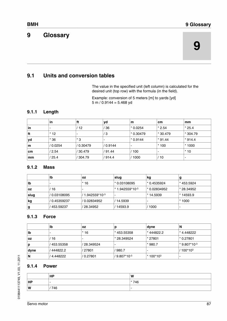
9 Glossary
9
9.1 Units and conversion tables
The value in the specified unit (left column) is calculated for thedesired unit (top row) with the formula (in the field).
Example: conversion of 5 meters [m] to yards [yd]5 m / 0.9144 = 5.468 yd
9.1.1 Length
in ft yd m cm mm
in - / 12 / 36 * 0.0254 * 2.54 * 25.4
ft * 12 - / 3 * 0.30479 * 30.479 * 304.79
yd * 36 * 3 - * 0.9144 * 91.44 * 914.4
m / 0.0254 / 0.30479 / 0.9144 - * 100 * 1000
cm / 2.54 / 30.479 / 91.44 / 100 - * 10
mm / 25.4 / 304.79 / 914.4 / 1000 / 10 -
9.1.2 Mass
lb oz slug kg g
lb - * 16 * 0.03108095 * 0.4535924 * 453.5924
oz / 16 - * 1.942559*10-3 * 0.02834952 * 28.34952
slug / 0.03108095 / 1.942559*10-3 - * 14.5939 * 14593.9
kg / 0.45359237 / 0.02834952 / 14.5939 - * 1000
g / 453.59237 / 28.34952 / 14593.9 / 1000 -
9.1.3 Force
lb oz p dyne N
lb - * 16 * 453.55358 * 444822.2 * 4.448222
oz / 16 - * 28.349524 * 27801 * 0.27801
p / 453.55358 / 28.349524 - * 980.7 * 9.807*10-3
dyne / 444822.2 / 27801 / 980.7 - / 100*103
N / 4.448222 / 0.27801 / 9.807*10-3 * 100*103 -
9.1.4 Power
HP W
HP - * 746
W / 746 -
BMH 9 Glossary
Servo motor 87
0198
4411
1374
9, V
1.03
, 11.
2011
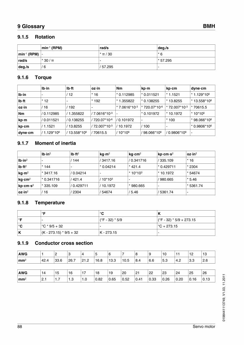
9.1.5 Rotation
min-1 (RPM) rad/s deg./s
min-1 (RPM) - * π / 30 * 6
rad/s * 30 / π - * 57.295
deg./s / 6 / 57.295 -
9.1.6 Torque
lb‧in lb‧ft oz‧in Nm kp‧m kp‧cm dyne‧cm
lb‧in - / 12 * 16 * 0.112985 * 0.011521 * 1.1521 * 1.129*106
lb‧ft * 12 - * 192 * 1.355822 * 0.138255 * 13.8255 * 13.558*106
oz‧in / 16 / 192 - * 7.0616*10-3 * 720.07*10-6 * 72.007*10-3 * 70615.5
Nm / 0.112985 / 1.355822 / 7.0616*10-3 - * 0.101972 * 10.1972 * 10*106
kp‧m / 0.011521 / 0.138255 / 720.07*10-6 / 0.101972 - * 100 * 98.066*106
kp‧cm / 1.1521 / 13.8255 / 72.007*10-3 / 10.1972 / 100 - * 0.9806*106
dyne‧cm / 1.129*106 / 13.558*106 / 70615.5 / 10*106 / 98.066*106 / 0.9806*106 -
9.1.7 Moment of inertia
lb‧in2 lb‧ft2 kg‧m2 kg‧cm2 kp‧cm‧s2 oz‧in2
lb‧in2 - / 144 / 3417.16 / 0.341716 / 335.109 * 16
lb‧ft2 * 144 - * 0.04214 * 421.4 * 0.429711 * 2304
kg‧m2 * 3417.16 / 0.04214 - * 10*103 * 10.1972 * 54674
kg‧cm2 * 0.341716 / 421.4 / 10*103 - / 980.665 * 5.46
kp‧cm‧s2 * 335.109 / 0.429711 / 10.1972 * 980.665 - * 5361.74
oz‧in2 / 16 / 2304 / 54674 / 5.46 / 5361.74 -
9.1.8 Temperature
°F °C K
°F - (°F - 32) * 5/9 (°F - 32) * 5/9 + 273.15
°C °C * 9/5 + 32 - °C + 273.15
K (K - 273.15) * 9/5 + 32 K - 273.15 -
9.1.9 Conductor cross section
AWG 1 2 3 4 5 6 7 8 9 10 11 12 13
mm2 42.4 33.6 26.7 21.2 16.8 13.3 10.5 8.4 6.6 5.3 4.2 3.3 2.6
AWG 14 15 16 17 18 19 20 21 22 23 24 25 26
mm2 2.1 1.7 1.3 1.0 0.82 0.65 0.52 0.41 0.33 0.26 0.20 0.16 0.13
9 Glossary BMH
88 Servo motor
0198
4411
1374
9, V
1.03
, 11.
2011
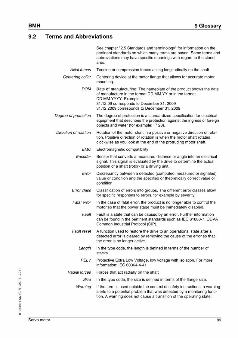
9.2 Terms and Abbreviations
See chapter "2.5 Standards and terminology" for information on thepertinent standards on which many terms are based. Some terms andabbreviations may have specific meanings with regard to the stand-ards.
Axial forces Tension or compression forces acting longitudinally on the shaft
Centering collar Centering device at the motor flange that allows for accurate motormounting.
DOM Date of manufacturing: The nameplate of the product shows the dateof manufacture in the format DD.MM.YY or in the formatDD.MM.YYYY. Example:31.12.09 corresponds to December 31, 2009 31.12.2009 corresponds to December 31, 2009
Degree of protection The degree of protection is a standardized specification for electricalequipment that describes the protection against the ingress of foreignobjects and water (for example: IP 20).
Direction of rotation Rotation of the motor shaft in a positive or negative direction of rota-tion. Positive direction of rotation is when the motor shaft rotatesclockwise as you look at the end of the protruding motor shaft.
EMC Electromagnetic compatibility
Encoder Sensor that converts a measured distance or angle into an electricalsignal. This signal is evaluated by the drive to determine the actualposition of a shaft (rotor) or a driving unit.
Error Discrepancy between a detected (computed, measured or signaled)value or condition and the specified or theoretically correct value orcondition.
Error class Classification of errors into groups. The different error classes allowfor specific responses to errors, for example by severity.
Fatal error In the case of fatal error, the product is no longer able to control themotor so that the power stage must be immediately disabled.
Fault Fault is a state that can be caused by an error. Further informationcan be found in the pertinent standards such as IEC 61800-7, ODVACommon Industrial Protocol (CIP).
Fault reset A function used to restore the drive to an operational state after adetected error is cleared by removing the cause of the error so thatthe error is no longer active.
Length In the type code, the length is defined in terms of the number ofstacks.
PELV Protective Extra Low Voltage, low voltage with isolation. For moreinformation: IEC 60364-4-41
Radial forces Forces that act radially on the shaft
Size In the type code, the size is defined in terms of the flange size.
Warning If the term is used outside the context of safety instructions, a warningalerts to a potential problem that was detected by a monitoring func-tion. A warning does not cause a transition of the operating state.
BMH 9 Glossary
Servo motor 89
0198
4411
1374
9, V
1.03
, 11.
2011

9 Glossary BMH
90 Servo motor
0198
4411
1374
9, V
1.03
, 11.
2011
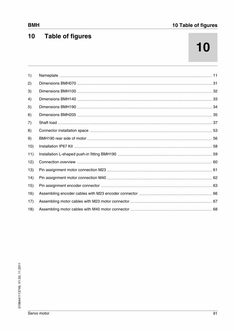
10 Table of figures
10
1) Nameplate 11
2) Dimensions BMH070 31
3) Dimensions BMH100 32
4) Dimensions BMH140 33
5) Dimensions BMH190 34
6) Dimensions BMH205 35
7) Shaft load 37
8) Connector installation space 53
9) BMH190 rear side of motor 56
10) Installation IP67 Kit 58
11) Installation L-shaped push-in fitting BMH190 59
12) Connection overview 60
13) Pin assignment motor connection M23 61
14) Pin assignment motor connection M40 62
15) Pin assignment encoder connector 63
16) Assembling encoder cables with M23 encoder connector 66
17) Assembling motor cables with M23 motor connector 67
18) Assembling motor cables with M40 motor connector 68
BMH 10 Table of figures
Servo motor 91
0198
4411
1374
9, V
1.03
, 11.
2011

10 Table of figures BMH
92 Servo motor
0198
4411
1374
9, V
1.03
, 11.
2011
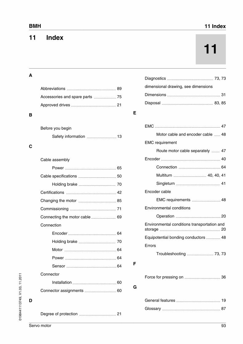
11 Index
11
A
Abbreviations 89
Accessories and spare parts 75
Approved drives 21
B
Before you begin
Safety information 13
C
Cable assembly
Power 65
Cable specifications 50
Holding brake 70
Certifications 42
Changing the motor 85
Commissioning 71
Connecting the motor cable 69
Connection
Encoder 64
Holding brake 70
Motor 64
Power 64
Sensor 64
Connector
Installation 60
Connector assignments 60
D
Degree of protection 21
Diagnostics 73, 73
dimensional drawing, see dimensions
Dimensions 31
Disposal 83, 85
E
EMC 47
Motor cable and encoder cable 48
EMC requirement
Route motor cable separately 47
Encoder 40
Connection 64
Multiturn 40, 40, 41
Singleturn 41
Encoder cable
EMC requirements 48
Environmental conditions
Operation 20
Environmental conditions transportation andstorage 20
Equipotential bonding conductors 48
Errors
Troubleshooting 73, 73
F
Force for pressing on 36
G
General features 19
Glossary 87
BMH 11 Index
Servo motor 93
0198
4411
1374
9, V
1.03
, 11.
2011
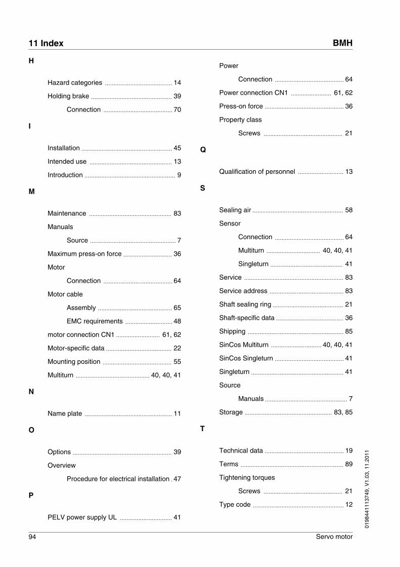
H
Hazard categories 14
Holding brake 39
Connection 70
I
Installation 45
Intended use 13
Introduction 9
M
Maintenance 83
Manuals
Source 7
Maximum press-on force 36
Motor
Connection 64
Motor cable
Assembly 65
EMC requirements 48
motor connection CN1 61, 62
Motor-specific data 22
Mounting position 55
Multiturn 40, 40, 41
N
Name plate 11
O
Options 39
Overview
Procedure for electrical installation 47
P
PELV power supply UL 41
Power
Connection 64
Power connection CN1 61, 62
Press-on force 36
Property class
Screws 21
Q
Qualification of personnel 13
S
Sealing air 58
Sensor
Connection 64
Multiturn 40, 40, 41
Singleturn 41
Service 83
Service address 83
Shaft sealing ring 21
Shaft-specific data 36
Shipping 85
SinCos Multiturn 40, 40, 41
SinCos Singleturn 41
Singleturn 41
Source
Manuals 7
Storage 83, 85
T
Technical data 19
Terms 89
Tightening torques
Screws 21
Type code 12
11 Index BMH
94 Servo motor
0198
4411
1374
9, V
1.03
, 11.
2011
U
UL, conditions for
PELV power supply 41
Wiring 41
Units and conversion tables 87
W
Wiring UL 41
BMH 11 Index
Servo motor 95
0198
4411
1374
9, V
1.03
, 11.
2011