blower door operation manual - california energy commission · 4.11 choose either a single or...
TRANSCRIPT
Retrotec Inc.
Blower Door Operation
Manual
For Series 200, 300, 1000
and 3000 systems
rev-2015-01-22
Page 2 of 83 ©Retrotec Inc. 2015
Made by Retrotec Inc.
1060 East Pole Road
Everson, WA USA 98247
For support:
Call 1(888) 330-1345 in USA
+1 (360) 738-9835 outside USA [email protected] or
Fax +1(360) 647-7724
Manual for:
Previous Models Q46, Q56, Q4E, Q5E, Q4E-2X, Q5E-2X Series 200, 300, 1000, 1100, 1200, 1300, 3100, 3200, 3300
Series 1000 includes the following Models*:
Model 1100 with DM-2 gauge Model 1101 with DM32 Model 1102 with DM32 WiFi
*See appendix E for complete Model list
Page 3 of 83 ©Retrotec Inc. 2015
Copyright © 2012-2015 Retrotec Inc.,
All rights reserved.
This document contains materials protected under International and Federal Copyright Laws. No part of this book may be reproduced or transmitted in any form or by any means, electronic or mechanical, including photocopying, recording, or by any information storage and retrieval system without express written permission from Retrotec Inc.
Retrotec makes no warranties with respect to this documentation and disclaims any implied warranties of merchantability, quality, or fitness for any particular purpose. The information in this document is subject to change without notice. Retrotec reserves the right to make revisions to this publication without obligation to notify any person or entity of any such changes.
DucTester, Infiltrometer and FanTestic are Trademarks of Retrotec Inc. Other trademarks or brand names mentioned herein are trademarks or registered trademarks of their respective owners.
Table of Contents
Important equipment-related safeguards ................................................................................................ 7
Important occupant safeguards during testing ........................................................................................ 8
1. How the Blower Door System components work .......................................... 9
1.1 How the Calibrated Fan creates flow and Fan Pressure ............................................................ 10
1.2 Range configurations restrict the fan’s air flow ........................................................................ 11
1.3 The Door Panel seals off a doorway and provides a fan mount................................................ 12
1.4 Gauge measures two pressures during the test ........................................................................ 12
1.5 A Fan Speed Controller sets the test pressure .......................................................................... 15
1.5.1. Use Speed Control Knob on the fan .................................................................................. 15
1.5.2. Control fan speed with a DM-2 gauge .............................................................................. 15
1.5.3. Use a Manual Speed Control accessory ............................................................................ 15
1.5.4. Use a Speed Control Splitter to control multiple fans ...................................................... 16
2. Choose a calibrated fan suited to your application ..................................... 20
2.1 Model 1000 for testing homes .................................................................................................. 20
2.2 Models 3300 and 3300SR high flow fans .................................................................................. 20
2.3 Model 200 (DucTester) or 300 fans for tight houses ................................................................ 21
2.4 Model 2350 for multiple fan applications ................................................................................. 23
2.5 Model 2100 fans (no longer available) ...................................................................................... 23
2.6 Model 2200 fan (no longer available) ....................................................................................... 24
3. Choose a Door Panel based on size of door and fans .................................. 26
3.1 Cloth Door Panel with Aluminum Frame ................................................................................... 26
3.1.1. Using the Aluminum Frame .............................................................................................. 27
3.1.2. Available Aluminum Frame Part Replacements ............................................................... 29
Page 4 of 83 ©Retrotec Inc. 2015
3.2 Modular Hard Sided Door Panels .............................................................................................. 29
3.2.1. Modular Door Panel Instructions ...................................................................................... 30
3.3 Triple-Fan Molded Panel Set for multiple fan tests ................................................................... 31
3.3.1. Using the Triple-Fan Molded Panel Set ............................................................................ 31
3.4 Compensating for Panel leakage ............................................................................................... 32
4. Conduct a Test ............................................................................................ 33
4.1 Observe house to avoid problems during testing ..................................................................... 33
4.1.1. Ashes and other materials can blow into house............................................................... 33
4.1.2. Doors can slam shut .......................................................................................................... 33
4.2 Select a Location ........................................................................................................................ 33
4.3 Where to place the exterior Pressure pickup tube ................................................................... 33
4.4 Determine if corrections for temperature difference are required .......................................... 34
4.5 Install the Door Fan for Depressurization test .......................................................................... 34
4.6 Set up the Gauge for the Appropriate Test ............................................................................... 34
4.7 Connect a Fan to the gauge (DM-2 or DM32) ........................................................................... 34
4.8 Select the correct Range configuration ..................................................................................... 35
4.9 Determine which Range to use on a Door Fan .......................................................................... 36
4.10 Cannot reach required pressure? .............................................................................................. 36
4.11 Choose either a Single or Multi- Point Test Procedure ............................................................. 37
4.12 Taking Manual Single Point Readings ........................................................................................ 37
4.12.1. Measure the Baseline Pressure before turning the fan on .............................................. 37
4.12.2. Adjust your test fan manually ........................................................................................... 37
4.12.3. Adjust your test fan using Set Pressure ............................................................................ 38
4.13 Taking Manual Multi-Point Readings for FanTestic Software ................................................... 38
4.13.1. Decide how many test points to take ............................................................................... 38
4.13.2. Decide whether to test in both directions ........................................................................ 39
4.13.3. Decide what is the optimum opening size on the fan (Range) ......................................... 39
4.13.4. Measure the Baseline (Zero Flow) Pressure before the test ............................................ 40
4.13.5. Measure each of the target points required for the test ................................................. 40
4.13.6. Complete taking the data set for this direction ................................................................ 41
4.13.7. Take another data set with fan flow in the other direction ............................................. 41
4.13.8. Enter collected data into FanTestic to get Results ........................................................... 41
4.14 Completely automated results using FanTestic ........................................................................ 43
4.15 Basic Results from Single Point Test .......................................................................................... 44
4.15.1. Air Leakage at 50 Pascal .................................................................................................... 44
Page 5 of 83 ©Retrotec Inc. 2015
4.15.2. Air Changes per hour at 50 Pa - ACH50 ............................................................................ 44
4.15.3. Equivalent Leakage Area - EqLA 10 ................................................................................... 44
4.15.4. Effective Leakage Area - EfLA 4 ......................................................................................... 44
4.16 Results from Multi-Point Procedure .......................................................................................... 44
5. Avoid Common Sources of Error ................................................................. 45
5.1 Wrong Range Configuration or Device ...................................................................................... 45
5.2 No Reference Tube when Pressurizing ...................................................................................... 45
5.3 Incorrect @ Pressure usage ....................................................................................................... 45
5.4 Choose the Appropriate Test Direction ..................................................................................... 45
5.5 Minimize effects of upstream Air Flow conditions .................................................................... 45
5.6 Considerations when operating with high backpressure .......................................................... 46
6. Maintain system for optimum operation .................................................... 47
6.1 Check motor and fan blade position ......................................................................................... 47
6.2 Check for Flow Sensor leaks ...................................................................................................... 47
6.3 Perform a field verification monthly ......................................................................................... 47
7. Power to run the fan and gauge ................................................................. 49
7.1 Status lights indicate power and control connections are ready to go ..................................... 49
7.2 Using the Fan with Mains Power ............................................................................................... 49
7.3 Using the Fan with a power generator ...................................................................................... 49
7.4 Recommended Generators ....................................................................................................... 50
7.4.1. Honda Generator EU2000 (120V, 2000W, 67 lbs) ............................................................ 50
7.4.2. GENYX G3000HI (230V, 3000W) generator ..................................................................... 50
7.5 Portable Power Supplies for DucTester ..................................................................................... 51
7.5.1. Black and Decker Electromate 400 Model VEC026BD ...................................................... 51
8. Fan Troubleshooting ................................................................................... 52
8.1 Retrotec 2000 series 120 Volt AC motors overheat and shut off ............................................. 52
8.2 3300 High Power Fan will not control smoothly ....................................................................... 52
8.3 3300 Fan will not start ............................................................................................................... 53
8.4 Power supply interior status light fault codes ........................................................................... 54
Appendix A: Calculate Airflow Manually .......................................................... 55
Appendix B: Find correct CFM at particular fan pressure .................................. 56
Appendix C: Find Door Fan System Part Numbers ............................................. 64
Fans & Accessories ................................................................................................................................. 64
Aluminum Frame .................................................................................................................................... 65
Page 6 of 83 ©Retrotec Inc. 2015
Cloth Door Panels ................................................................................................................................... 66
Modular Door Panels .............................................................................................................................. 68
Digital Gauges ......................................................................................................................................... 70
System Accessories ................................................................................................................................. 70
Appendix D: Optional Door Fan system components ........................................ 73
Flex Duct to measure air flow or neutralize pressure drops .................................................................. 73
Wind Damping Kits to minimize wind effects ........................................................................................ 74
Cases and Bags........................................................................................................................................ 74
Grill Mask and Dispensers ...................................................................................................................... 74
Air Current Testers.................................................................................................................................. 74
Appendix E: Model and System Names ............................................................. 76
Glossary ............................................................................................................ 81
Page 7 of 83 ©Retrotec Inc. 2015
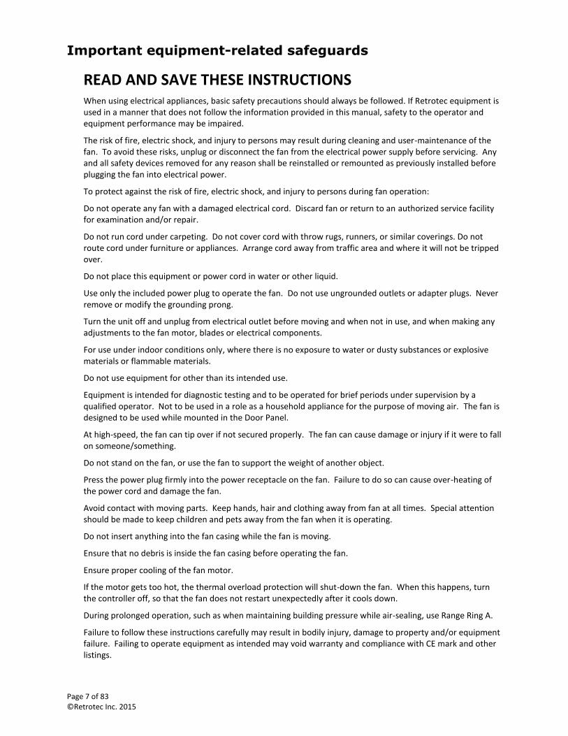
Important equipment-related safeguards
READ AND SAVE THESE INSTRUCTIONS When using electrical appliances, basic safety precautions should always be followed. If Retrotec equipment is used in a manner that does not follow the information provided in this manual, safety to the operator and equipment performance may be impaired.
The risk of fire, electric shock, and injury to persons may result during cleaning and user-maintenance of the fan. To avoid these risks, unplug or disconnect the fan from the electrical power supply before servicing. Any and all safety devices removed for any reason shall be reinstalled or remounted as previously installed before plugging the fan into electrical power.
To protect against the risk of fire, electric shock, and injury to persons during fan operation:
Do not operate any fan with a damaged electrical cord. Discard fan or return to an authorized service facility for examination and/or repair.
Do not run cord under carpeting. Do not cover cord with throw rugs, runners, or similar coverings. Do not route cord under furniture or appliances. Arrange cord away from traffic area and where it will not be tripped over.
Do not place this equipment or power cord in water or other liquid.
Use only the included power plug to operate the fan. Do not use ungrounded outlets or adapter plugs. Never remove or modify the grounding prong.
Turn the unit off and unplug from electrical outlet before moving and when not in use, and when making any adjustments to the fan motor, blades or electrical components.
For use under indoor conditions only, where there is no exposure to water or dusty substances or explosive materials or flammable materials.
Do not use equipment for other than its intended use.
Equipment is intended for diagnostic testing and to be operated for brief periods under supervision by a qualified operator. Not to be used in a role as a household appliance for the purpose of moving air. The fan is designed to be used while mounted in the Door Panel.
At high-speed, the fan can tip over if not secured properly. The fan can cause damage or injury if it were to fall on someone/something.
Do not stand on the fan, or use the fan to support the weight of another object.
Press the power plug firmly into the power receptacle on the fan. Failure to do so can cause over-heating of the power cord and damage the fan.
Avoid contact with moving parts. Keep hands, hair and clothing away from fan at all times. Special attention should be made to keep children and pets away from the fan when it is operating.
Do not insert anything into the fan casing while the fan is moving.
Ensure that no debris is inside the fan casing before operating the fan.
Ensure proper cooling of the fan motor.
If the motor gets too hot, the thermal overload protection will shut-down the fan. When this happens, turn the controller off, so that the fan does not restart unexpectedly after it cools down.
During prolonged operation, such as when maintaining building pressure while air-sealing, use Range Ring A.
Failure to follow these instructions carefully may result in bodily injury, damage to property and/or equipment failure. Failing to operate equipment as intended may void warranty and compliance with CE mark and other listings.
Page 8 of 83 ©Retrotec Inc. 2015
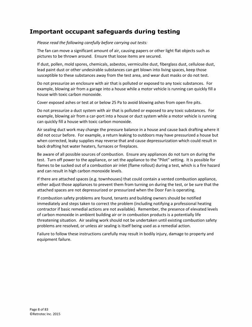
Important occupant safeguards during testing
Please read the following carefully before carrying out tests:
The fan can move a significant amount of air, causing papers or other light flat objects such as pictures to be thrown around. Ensure that loose items are secured.
If dust, pollen, mold spores, chemicals, asbestos, vermiculite dust, fiberglass dust, cellulose dust, lead paint dust or other undesirable substances can get blown into living spaces, keep those susceptible to these substances away from the test area, and wear dust masks or do not test.
Do not pressurize an enclosure with air that is polluted or exposed to any toxic substances. For example, blowing air from a garage into a house while a motor vehicle is running can quickly fill a house with toxic carbon monoxide.
Cover exposed ashes or test at or below 25 Pa to avoid blowing ashes from open fire pits.
Do not pressurize a duct system with air that is polluted or exposed to any toxic substances. For example, blowing air from a car-port into a house or duct system while a motor vehicle is running can quickly fill a house with toxic carbon monoxide.
Air sealing duct work may change the pressure balance in a house and cause back drafting where it did not occur before. For example, a return leaking to outdoors may have pressurized a house but when corrected, leaky supplies may reverse that and cause depressurization which could result in back drafting hot water heaters, furnaces or fireplaces.
Be aware of all possible sources of combustion. Ensure any appliances do not turn on during the test. Turn off power to the appliance, or set the appliance to the "Pilot" setting. It is possible for flames to be sucked out of a combustion air inlet (flame rollout) during a test, which is a fire hazard and can result in high carbon monoxide levels.
If there are attached spaces (e.g. townhouses) that could contain a vented combustion appliance, either adjust those appliances to prevent them from turning on during the test, or be sure that the attached spaces are not depressurized or pressurized when the Door Fan is operating.
If combustion safety problems are found, tenants and building owners should be notified immediately and steps taken to correct the problem (including notifying a professional heating contractor if basic remedial actions are not available). Remember, the presence of elevated levels of carbon monoxide in ambient building air or in combustion products is a potentially life threatening situation. Air sealing work should not be undertaken until existing combustion safety problems are resolved, or unless air sealing is itself being used as a remedial action.
Failure to follow these instructions carefully may result in bodily injury, damage to property and equipment failure.
Page 9 of 83 ©Retrotec Inc. 2015
1. How the Blower Door System components work
A Door Fan is a specially designed calibrated fan which, as part of the Blower Door Fan System, is temporarily mounted in a doorway. The fan is used to blow air into or out of a room, house, or building to measure the air leakage of the enclosure. The term “room, house, or building” is often shortened to “enclosure”.
The Door Fan System works by establishing a pressure difference between the inside and the outside of an enclosure. The pressure difference forces air to leak through all of the holes in the exterior envelope of the enclosure. The amount of air flow that is required to maintain a constant pressure difference is equal to the amount of air that is leaking from the enclosure. A specially designed gauge can thus be used to measure the pressure difference and calculate the amount of air flowing through the Door Fan, which can then be used to determine the total size of all those leaks.
A typical Door Fan or Door Fan system is comprised of four main parts:
1. A Door Panel, which temporarily seals a typical doorway and provides a hole to mount a fan.
2. A calibrated fan, capable of creating a measurable flow of air.
3. A two-channel differential pressure gauge that can also calculate flow for a particular fan.
4. A fan speed controller to change the air flow through the fan (which can be provided by the gauge)
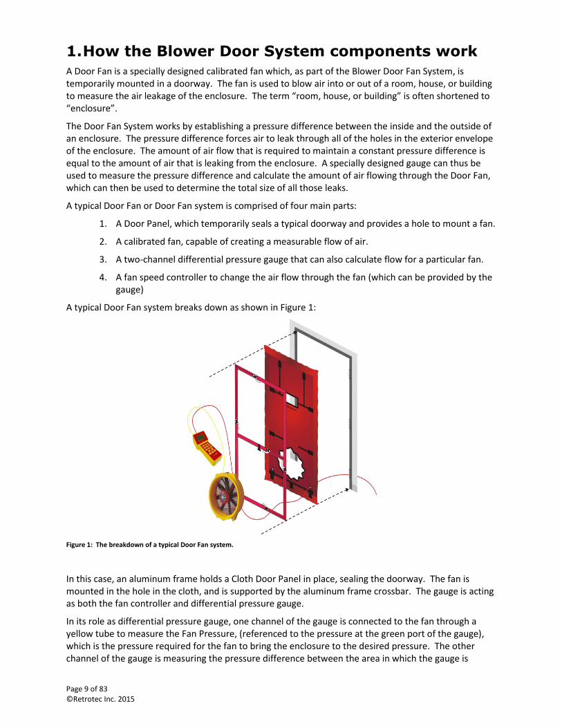
A typical Door Fan system breaks down as shown in Figure 1:
Figure 1: The breakdown of a typical Door Fan system.
In this case, an aluminum frame holds a Cloth Door Panel in place, sealing the doorway. The fan is mounted in the hole in the cloth, and is supported by the aluminum frame crossbar. The gauge is acting as both the fan controller and differential pressure gauge.
In its role as differential pressure gauge, one channel of the gauge is connected to the fan through a yellow tube to measure the Fan Pressure, (referenced to the pressure at the green port of the gauge), which is the pressure required for the fan to bring the enclosure to the desired pressure. The other channel of the gauge is measuring the pressure difference between the area in which the gauge is
Page 10 of 83 ©Retrotec Inc. 2015
located (on the blue port of the gauge) and the other side of the doorway, since the red tube is run through a small hole in the cloth to the other side of the doorway and acts as a reference for the measurement.
In its role as a fan speed controller, the gauge is connected to the fan through an electrical connector, (yellow Speed Control Cable), and changes the speed of the fan until the pressure difference across the doorway reaches the desired test condition. The Speed Control Cable can extend approximately 1,200 meters (4,000 feet) between the gauge and the fan.
Knowing the pressure difference tells the operator when the enclosure has reached the desired condition (50 Pa for instance). Knowing the Fan Pressure and the fan calibration allows the operator, or the gauge itself, to calculate the air flow (CFM for instance).
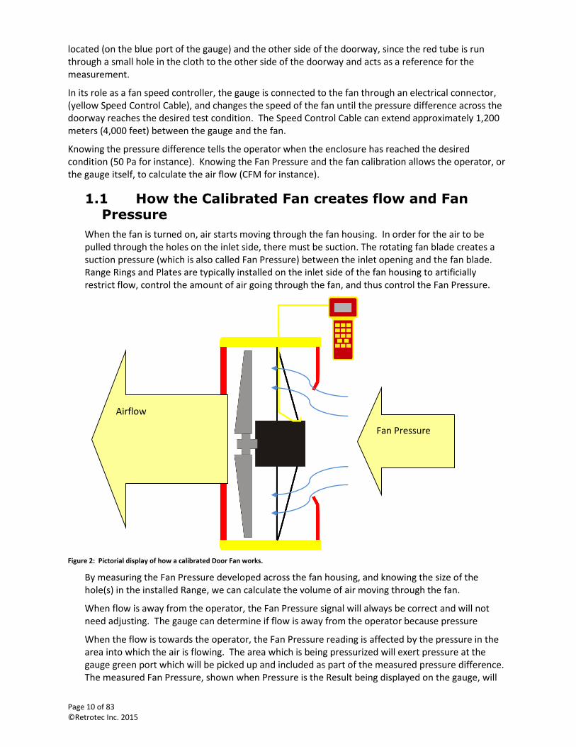
1.1 How the Calibrated Fan creates flow and Fan Pressure
When the fan is turned on, air starts moving through the fan housing. In order for the air to be pulled through the holes on the inlet side, there must be suction. The rotating fan blade creates a suction pressure (which is also called Fan Pressure) between the inlet opening and the fan blade. Range Rings and Plates are typically installed on the inlet side of the fan housing to artificially restrict flow, control the amount of air going through the fan, and thus control the Fan Pressure.
Figure 2: Pictorial display of how a calibrated Door Fan works.
By measuring the Fan Pressure developed across the fan housing, and knowing the size of the hole(s) in the installed Range, we can calculate the volume of air moving through the fan.
When flow is away from the operator, the Fan Pressure signal will always be correct and will not need adjusting. The gauge can determine if flow is away from the operator because pressure
When the flow is towards the operator, the Fan Pressure reading is affected by the pressure in the area into which the air is flowing. The area which is being pressurized will exert pressure at the gauge green port which will be picked up and included as part of the measured pressure difference. The measured Fan Pressure, shown when Pressure is the Result being displayed on the gauge, will
Fan Pressure
Airflow
Page 11 of 83 ©Retrotec Inc. 2015
thus include the actual Fan Pressure as well as the additional pressure in the room where the operator is standing. So when the flow is towards the operator, this room pressure must be removed from the measurement to get the true Fan Pressure, before calculating flow.
A self-referencing fan avoids the need for adjusting Fan Pressure measurements by measuring the pressure difference at the fan inlet directly with both the green and yellow tubes connected to either side of the fan inlet on Retrotec fans. The Fan Pressure difference is thus always correct when measured between the yellow and green port at the gauge.
If a self-referencing fan is in use (both yellow and green tubes are connected between the fan and the gauge), it is imperative to choose 3000SR for the Device on the gauge (or the DucTester), so the gauge does not compensate for the room pressure in any situation.
The gauge can determine when flow is toward the operator because the readings on Channel A will always be positive (assuming the gauge is set up with the blue port measuring the pressure of the room in which the operator is standing, and the red tube runs to the opposite side). Thus, if a device that is not self-referencing is chosen on the gauge, (any device except the DucTester and those denoted SR), and Channel A readings are positive, the gauge compensates: the measured pressure from the fan, “PrB”, is reduced by the room pressure being measured on Channel A, “PrA”. The gauge then uses the adjusted value, the actual Fan Pressure, to calculate the airflow displayed as Mode “Flow” or any other Mode result except “PrB”. When the Mode is set to “PrB”, the gauge always shows the actual pressure difference measured on Channel B, which includes both the fan pressure and the additional pressure in the room where the operator is standing, when flow is towards the operator.
Other manufacturers’ digital gauges need to have the pressure signal from the fan corrected to the actual Fan Pressure before the Fan Pressure value is used to calculate air flow. When flow is towards the operator, the procedure is to subtract the Room Pressure from the Fan Pressure to determine the actual Fan Pressure.
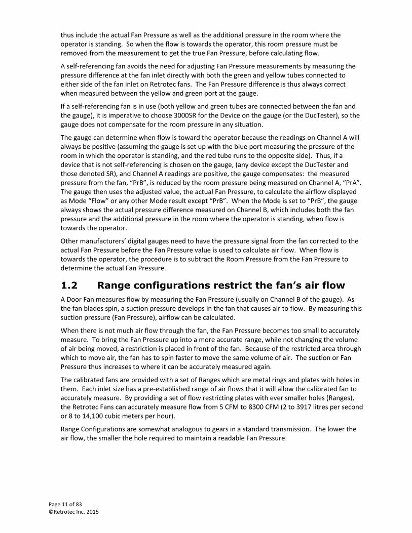
1.2 Range configurations restrict the fan’s air flow
A Door Fan measures flow by measuring the Fan Pressure (usually on Channel B of the gauge). As the fan blades spin, a suction pressure develops in the fan that causes air to flow. By measuring this suction pressure (Fan Pressure), airflow can be calculated.
When there is not much air flow through the fan, the Fan Pressure becomes too small to accurately measure. To bring the Fan Pressure up into a more accurate range, while not changing the volume of air being moved, a restriction is placed in front of the fan. Because of the restricted area through which to move air, the fan has to spin faster to move the same volume of air. The suction or Fan Pressure thus increases to where it can be accurately measured again.
The calibrated fans are provided with a set of Ranges which are metal rings and plates with holes in them. Each inlet size has a pre-established range of air flows that it will allow the calibrated fan to accurately measure. By providing a set of flow restricting plates with ever smaller holes (Ranges), the Retrotec Fans can accurately measure flow from 5 CFM to 8300 CFM (2 to 3917 litres per second or 8 to 14,100 cubic meters per hour).
Range Configurations are somewhat analogous to gears in a standard transmission. The lower the air flow, the smaller the hole required to maintain a readable Fan Pressure.
Page 12 of 83 ©Retrotec Inc. 2015
Figure 3: Range Configuration components for 2000/3000 series fans.
See section 4.3 and 4.9 for details on how to select the correct Range Configuration for the test.
1.3 The Door Panel seals off a doorway and provides a fan mount
Retrotec offers three types of Door Panels. The most common style of Door Panel is a Cloth Door Panel on an aluminum frame. Modular Door Panels are a set of solid panels that expand to fit most doors, and offer a quick setup or take down option that is professional looking and easy to carry. For large buildings, three fans can be mounted in one Three-Fan Panel, to maximize the airflow pushed through one doorway.
See section 3 for details on each type of Door Panel, and set up instructions.
1.4 Gauge measures two pressures during the test
The Retrotec digital gauges (DM32 or DM-2) are two channel differential pressure gauges. A differential pressure gauge measures the pressure difference between two locations. The gauge provides two channels, each of which can measure a pressure difference (between 2 ports). Channel A measures the difference in pressure between the blue and red ports, and Channel B measures the pressure difference between the green and yellow ports. The gauge can also provide fan speed control functions, as outlined in section 0.
In its role as a two channel differential pressure gauge during the Blower Door test, one channel of the gauge is used to measure the Fan Pressure and one channel is used to measure the Room or Induced Pressure. The Fan Pressure is the pressure inside the fan that is developed while the fan brings the room to the test pressure. The Room or Induced Pressure is the pressure difference between the area in which the gauge is located, and the other side of the Door Panel.
To measure the Fan Pressure difference between the fan interior and the pressure at the green port on the gauge, the yellow port on the gauge is connected to the fan through a yellow tube. If the fan provides a green port (fan is self-referencing), the green port on the gauge should also be connected to the green port on the fan.
To measure Room Pressure, the red tube is connected to the red port on the gauge and then run through a small hole in the cloth to the other side of the Door Panel. The blue port on the gauge is open to the pressure in the room so the difference between the pressure in the room and the other side of the Door Panel is measured on Channel A.
It is very simple to connect a Retrotec fan to the digital gauge. Depending on which model fan is in use, there will be some combination of red, blue, green, and yellow pressure tubes included. These
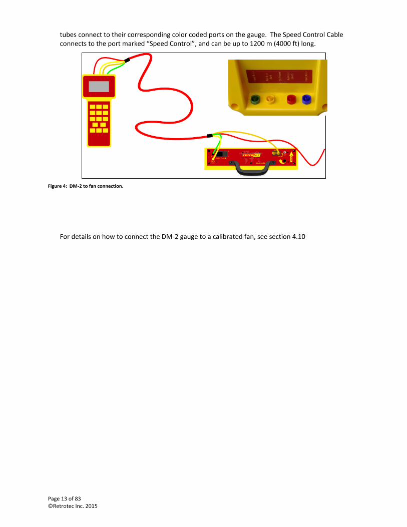
Page 13 of 83 ©Retrotec Inc. 2015
tubes connect to their corresponding color coded ports on the gauge. The Speed Control Cable connects to the port marked “Speed Control”, and can be up to 1200 m (4000 ft) long.
Figure 4: DM-2 to fan connection.
For details on how to connect the DM-2 gauge to a calibrated fan, see section 4.10
Retrotec Inc.
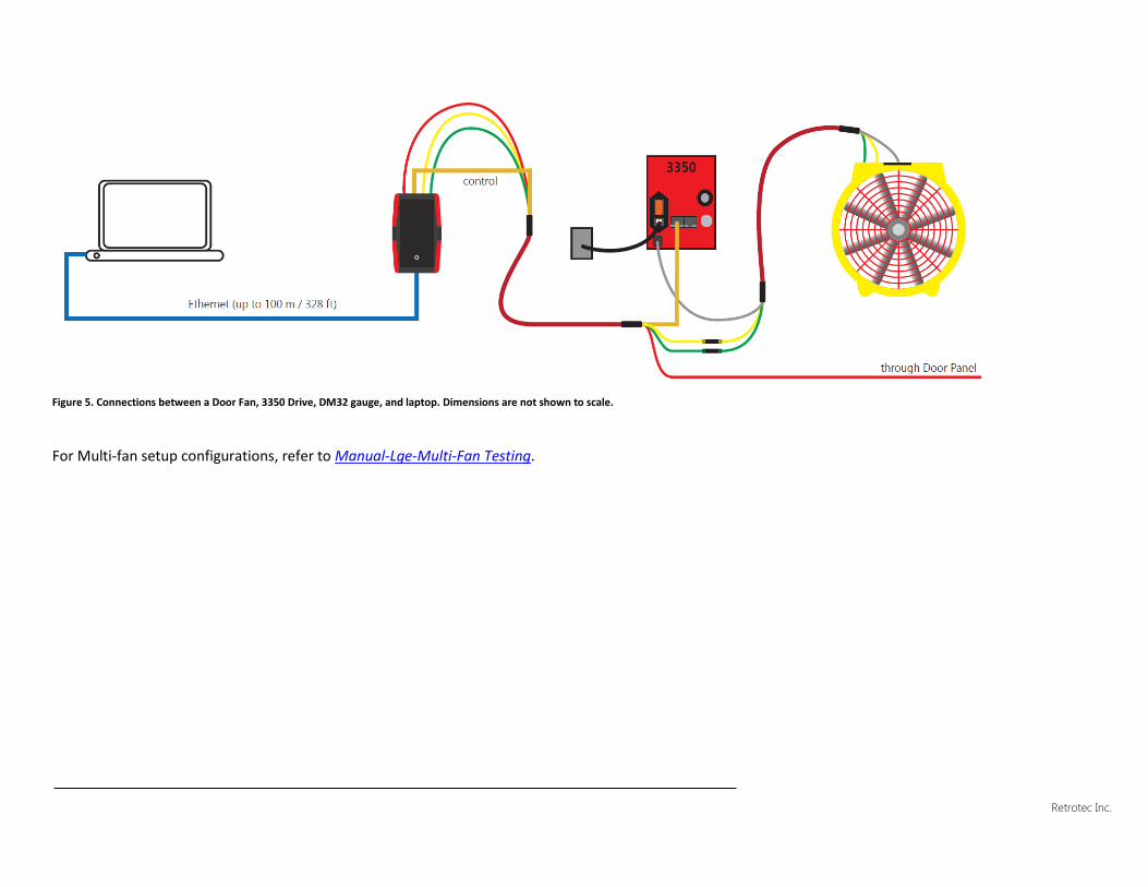
Figure 5. Connections between a Door Fan, 3350 Drive, DM32 gauge, and laptop. Dimensions are not shown to scale.
For Multi-fan setup configurations, refer to Manual-Lge-Multi-Fan Testing.
Retrotec Inc.
1.5 A Fan Speed Controller sets the test pressure
If operating the Blower Door Fan System manually, a knob on the fan or a Manual Speed Control accessory allows the speed of a fan to be controlled by turning a knob/dial. Otherwise, speed can be controlled from the DM-2 or DM32 gauge.
The gauge can operate as a fan speed controller in addition to being a two channel differential pressure gauge. In its role as a fan speed controller, the gauge is connected to the fan through an electrical control connector and changes the speed of the fan until the pressure difference across the doorway reaches the desired test condition.
For instructions on connecting and operating each controller, see section 1.5.1 for the Fan Top speed control, section 1.5.3 for the Manual Speed Control accessory, and section 1.5.2 to operate the gauge speed control function.
The Fan Speed Control output on the gauge speed control cable which connects to the fan uses RS-485 protocol. This protocol allows the Speed Control Cable to extend approximately 1,200 metres (4,000 feet) between the gauge and the fan.
A speed control splitter can be used to control more than one fan with a single gauge, see section 1.5.4.
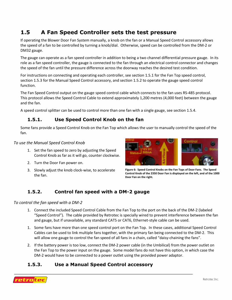
1.5.1. Use Speed Control Knob on the fan
Some fans provide a Speed Control Knob on the Fan Top which allows the user to manually control the speed of the fan.
To use the Manual Speed Control Knob
1. Set the fan speed to zero by adjusting the Speed Control Knob as far as it will go, counter clockwise.
2. Turn the Door Fan power on.
3. Slowly adjust the knob clock-wise, to accelerate the fan.
1.5.2. Control fan speed with a DM-2 gauge
To control the fan speed with a DM-2
1. Connect the included Speed Control Cable from the Fan Top to the port on the back of the DM-2 (labeled “Speed Control”). The cable provided by Retrotec is specially wired to prevent interference between the fan and gauge, but if unavailable, any standard CAT5 or CAT6, Ethernet-style cable can be used.
1. Some fans have more than one speed control port on the Fan Top. In these cases, additional Speed Control Cables can be used to link multiple fans together, with the primary fan being connected to the DM-2. This will allow one gauge to control the fan speed of all fans in a chain, called “daisy-chaining the fans”.
2. If the battery power is too low, connect the DM-2 power cable (in the Umbilical) from the power outlet on the Fan Top to the power input on the gauge. Some model fans do not have this option, in which case the DM-2 would have to be connected to a power outlet using the provided power adaptor.
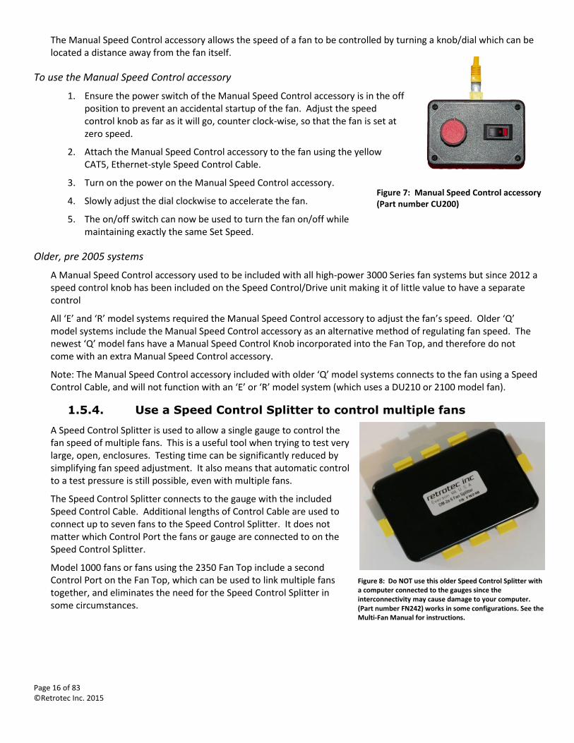
1.5.3. Use a Manual Speed Control accessory
Figure 6: Speed Control Knobs on the Fan Tops of Door Fans. The Speed Control Knob of the 2350 Door Fan is displayed on the left, and of the 1000 Door Fan on the right.
Page 16 of 83 ©Retrotec Inc. 2015
The Manual Speed Control accessory allows the speed of a fan to be controlled by turning a knob/dial which can be located a distance away from the fan itself.
To use the Manual Speed Control accessory
1. Ensure the power switch of the Manual Speed Control accessory is in the off position to prevent an accidental startup of the fan. Adjust the speed control knob as far as it will go, counter clock-wise, so that the fan is set at zero speed.
2. Attach the Manual Speed Control accessory to the fan using the yellow CAT5, Ethernet-style Speed Control Cable.
3. Turn on the power on the Manual Speed Control accessory.
4. Slowly adjust the dial clockwise to accelerate the fan.
5. The on/off switch can now be used to turn the fan on/off while maintaining exactly the same Set Speed.
Older, pre 2005 systems
A Manual Speed Control accessory used to be included with all high-power 3000 Series fan systems but since 2012 a speed control knob has been included on the Speed Control/Drive unit making it of little value to have a separate control
All ‘E’ and ‘R’ model systems required the Manual Speed Control accessory to adjust the fan’s speed. Older ‘Q’ model systems include the Manual Speed Control accessory as an alternative method of regulating fan speed. The newest ‘Q’ model fans have a Manual Speed Control Knob incorporated into the Fan Top, and therefore do not come with an extra Manual Speed Control accessory.
Note: The Manual Speed Control accessory included with older ‘Q’ model systems connects to the fan using a Speed Control Cable, and will not function with an ‘E’ or ‘R’ model system (which uses a DU210 or 2100 model fan).
1.5.4. Use a Speed Control Splitter to control multiple fans
A Speed Control Splitter is used to allow a single gauge to control the fan speed of multiple fans. This is a useful tool when trying to test very large, open, enclosures. Testing time can be significantly reduced by simplifying fan speed adjustment. It also means that automatic control to a test pressure is still possible, even with multiple fans.
The Speed Control Splitter connects to the gauge with the included Speed Control Cable. Additional lengths of Control Cable are used to connect up to seven fans to the Speed Control Splitter. It does not matter which Control Port the fans or gauge are connected to on the Speed Control Splitter.
Model 1000 fans or fans using the 2350 Fan Top include a second Control Port on the Fan Top, which can be used to link multiple fans together, and eliminates the need for the Speed Control Splitter in some circumstances.
Figure 8: Do NOT use this older Speed Control Splitter with a computer connected to the gauges since the interconnectivity may cause damage to your computer. (Part number FN242) works in some configurations. See the Multi-Fan Manual for instructions.
Figure 7: Manual Speed Control accessory (Part number CU200)
Page 17 of 83 ©Retrotec Inc. 2015
While the gauge connected to the Speed Control Splitter will control the fan speed of all connected fans, it can only measure the Fan Pressure from one fan.
Flow and/or Fan Pressure will still need to be measured simultaneously from each fan to get accurate airflow results. Do not add the measured Fan Pressure from each fan. Instead, convert the Fan Pressure to CFM (flow) (or adjust the gauge to display Flow in CFM), then add the numbers for flow together.
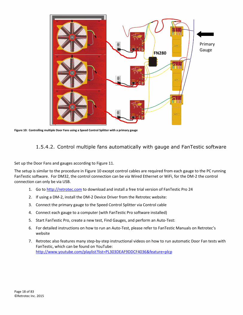
1.5.4.1. Control multiple fans using one primary gauge
Set up the Door Fans and digital gauges according to Figure 10 and the following procedure.
Controlling multiple Door Fans using a Speed Control Splitter
1. Set up Door Fans in doorway(s)
2. Connect Drives to Door Fans using the Drives’ Umbilical
3. Connect yellow and green tubes from the gauge to each Drive
4. Connect Control Cables from each Drive to the Speed Control Splitter (Model: FN280)
5. Connect a Control Cable from the Speed Control Splitter to one gauge (“Primary Gauge”)
6. T-connect the red tubing from each of the gauges together
7. T-connect the blue tubing from each of the gauges together
8. Pass the red tube through the port in the panel and toss away from the Door Fans’ airstream
9. Use [Set Speed] or [Set Pressure] function on the Primary Gauge to control the same speed on all Door Fans
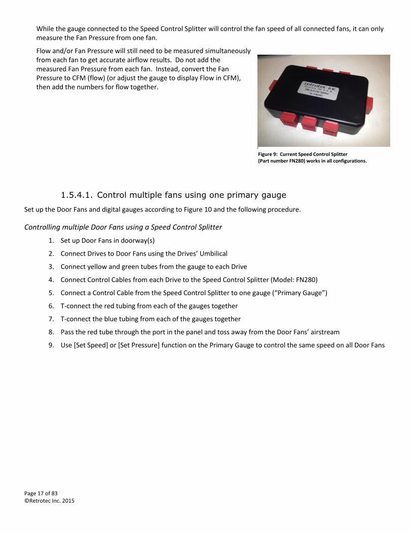
Figure 9: Current Speed Control Splitter (Part number FN280) works in all configurations.
Page 18 of 83 ©Retrotec Inc. 2015
Figure 10: Controlling multiple Door Fans using a Speed Control Splitter with a primary gauge
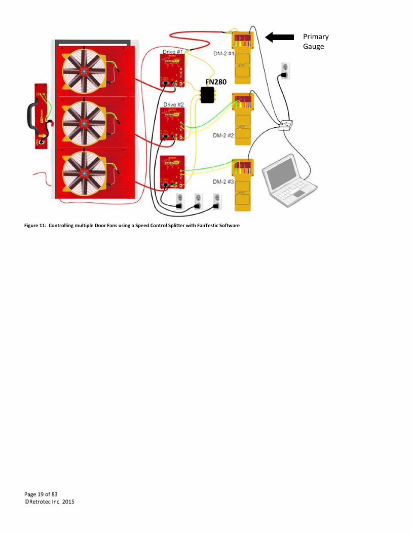
1.5.4.2. Control multiple fans automatically with gauge and FanTestic software
Set up the Door Fans and gauges according to Figure 11.
The setup is similar to the procedure in Figure 10 except control cables are required from each gauge to the PC running FanTestic software. For DM32, the control connection can be via Wired Ethernet or WiFi, for the DM-2 the control connection can only be via USB.
1. Go to http://retrotec.com to download and install a free trial version of FanTestic Pro 24
2. If using a DM-2, install the DM-2 Device Driver from the Retrotec website:
3. Connect the primary gauge to the Speed Control Splitter via Control cable
4. Connect each gauge to a computer (with FanTestic Pro software installed)
5. Start FanTestic Pro, create a new test, Find Gauges, and perform an Auto-Test:
6. For detailed instructions on how to run an Auto-Test, please refer to FanTestic Manuals on Retrotec’s website
7. Retrotec also features many step-by-step instructional videos on how to run automatic Door Fan tests with FanTestic, which can be found on YouTube: http://www.youtube.com/playlist?list=PL303DEAF9DDCF4036&feature=plcp
Primary Gauge
FN280
Page 19 of 83 ©Retrotec Inc. 2015
Figure 11: Controlling multiple Door Fans using a Speed Control Splitter with FanTestic Software
FN280
Primary Gauge
Page 20 of 83 ©Retrotec Inc. 2015
2. Choose a calibrated fan suited to your application
Retrotec has a number of calibrated fans designed to operate under different conditions and with different features suited to the various applications.
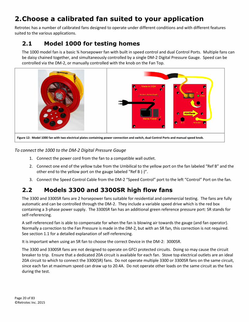
2.1 Model 1000 for testing homes
The 1000 model fan is a basic ¾ horsepower fan with built in speed control and dual Control Ports. Multiple fans can be daisy chained together, and simultaneously controlled by a single DM-2 Digital Pressure Gauge. Speed can be controlled via the DM-2, or manually controlled with the knob on the Fan Top.
Figure 12: Model 1000 fan with two electrical plates containing power connection and switch, dual Control Ports and manual speed knob.
To connect the 1000 to the DM-2 Digital Pressure Gauge
1. Connect the power cord from the fan to a compatible wall outlet.
2. Connect one end of the yellow tube from the Umbilical to the yellow port on the fan labeled “Ref B” and the other end to the yellow port on the gauge labeled “Ref B (-)”.
3. Connect the Speed Control Cable from the DM-2 “Speed Control” port to the left “Control” Port on the fan.
2.2 Models 3300 and 3300SR high flow fans
The 3300 and 3300SR fans are 2 horsepower fans suitable for residential and commercial testing. The fans are fully automatic and can be controlled through the DM-2. They include a variable speed drive which is the red box containing a 3-phase power supply. The 3300SR fan has an additional green reference pressure port: SR stands for self-referencing.
A self-referenced fan is able to compensate for when the fan is blowing air towards the gauge (and fan operator). Normally a correction to the Fan Pressure is made in the DM-2, but with an SR fan, this correction is not required. See section 1.1 for a detailed explanation of self-referencing.
It is important when using an SR fan to choose the correct Device in the DM-2: 3000SR.
The 3300 and 3300SR fans are not designed to operate on GFCI protected circuits. Doing so may cause the circuit breaker to trip. Ensure that a dedicated 20A circuit is available for each fan. Stove top electrical outlets are an ideal 20A circuit to which to connect the 3300(SR) fans. Do not operate multiple 3300 or 3300SR fans on the same circuit, since each fan at maximum speed can draw up to 20.4A. Do not operate other loads on the same circuit as the fans during the test.
Page 21 of 83 ©Retrotec Inc. 2015
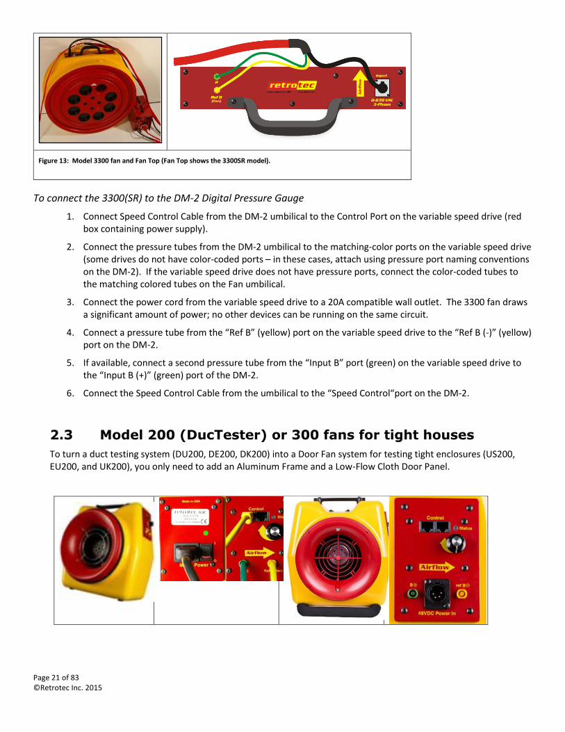
Figure 13: Model 3300 fan and Fan Top (Fan Top shows the 3300SR model).
To connect the 3300(SR) to the DM-2 Digital Pressure Gauge
1. Connect Speed Control Cable from the DM-2 umbilical to the Control Port on the variable speed drive (red box containing power supply).
2. Connect the pressure tubes from the DM-2 umbilical to the matching-color ports on the variable speed drive (some drives do not have color-coded ports – in these cases, attach using pressure port naming conventions on the DM-2). If the variable speed drive does not have pressure ports, connect the color-coded tubes to the matching colored tubes on the Fan umbilical.
3. Connect the power cord from the variable speed drive to a 20A compatible wall outlet. The 3300 fan draws a significant amount of power; no other devices can be running on the same circuit.
4. Connect a pressure tube from the “Ref B” (yellow) port on the variable speed drive to the “Ref B (-)” (yellow) port on the DM-2.
5. If available, connect a second pressure tube from the “Input B” port (green) on the variable speed drive to the “Input B (+)” (green) port of the DM-2.
6. Connect the Speed Control Cable from the umbilical to the “Speed Control“port on the DM-2.
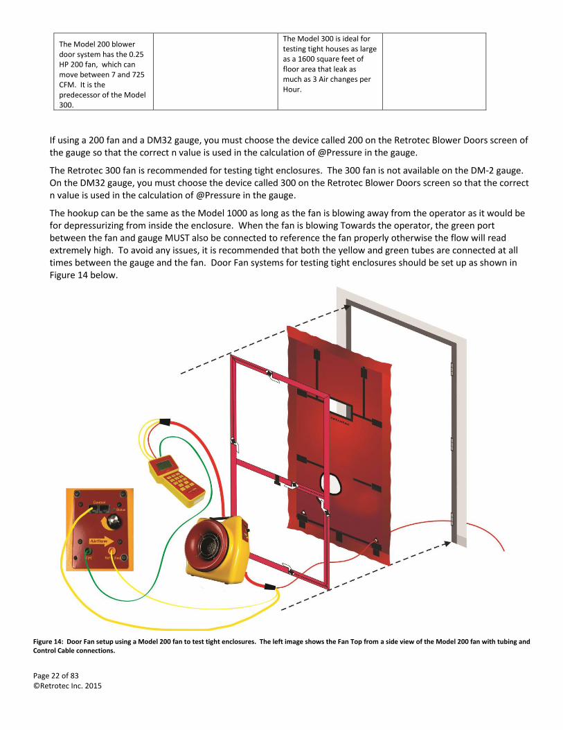
2.3 Model 200 (DucTester) or 300 fans for tight houses
To turn a duct testing system (DU200, DE200, DK200) into a Door Fan system for testing tight enclosures (US200, EU200, and UK200), you only need to add an Aluminum Frame and a Low-Flow Cloth Door Panel.
Page 22 of 83 ©Retrotec Inc. 2015
The Model 200 blower door system has the 0.25 HP 200 fan, which can move between 7 and 725 CFM. It is the predecessor of the Model 300.
The Model 300 is ideal for testing tight houses as large as a 1600 square feet of floor area that leak as much as 3 Air changes per Hour.
If using a 200 fan and a DM32 gauge, you must choose the device called 200 on the Retrotec Blower Doors screen of the gauge so that the correct n value is used in the calculation of @Pressure in the gauge.
The Retrotec 300 fan is recommended for testing tight enclosures. The 300 fan is not available on the DM-2 gauge. On the DM32 gauge, you must choose the device called 300 on the Retrotec Blower Doors screen so that the correct n value is used in the calculation of @Pressure in the gauge.
The hookup can be the same as the Model 1000 as long as the fan is blowing away from the operator as it would be for depressurizing from inside the enclosure. When the fan is blowing Towards the operator, the green port between the fan and gauge MUST also be connected to reference the fan properly otherwise the flow will read extremely high. To avoid any issues, it is recommended that both the yellow and green tubes are connected at all times between the gauge and the fan. Door Fan systems for testing tight enclosures should be set up as shown in Figure 14 below.
Figure 14: Door Fan setup using a Model 200 fan to test tight enclosures. The left image shows the Fan Top from a side view of the Model 200 fan with tubing and Control Cable connections.
Page 23 of 83 ©Retrotec Inc. 2015
Note: The green tube Must be connected if the flow is towards the operator (i.e. air is blowing towards where the operator is standing), and is recommended to be connected at all times so the correct Fan Pressure is used in all calculations under all circumstances.
The Speed Control Cable can be plugged into either one of the two Control ports on the fan.
For Door Fan testing, refer to procedures outlined in section 4.
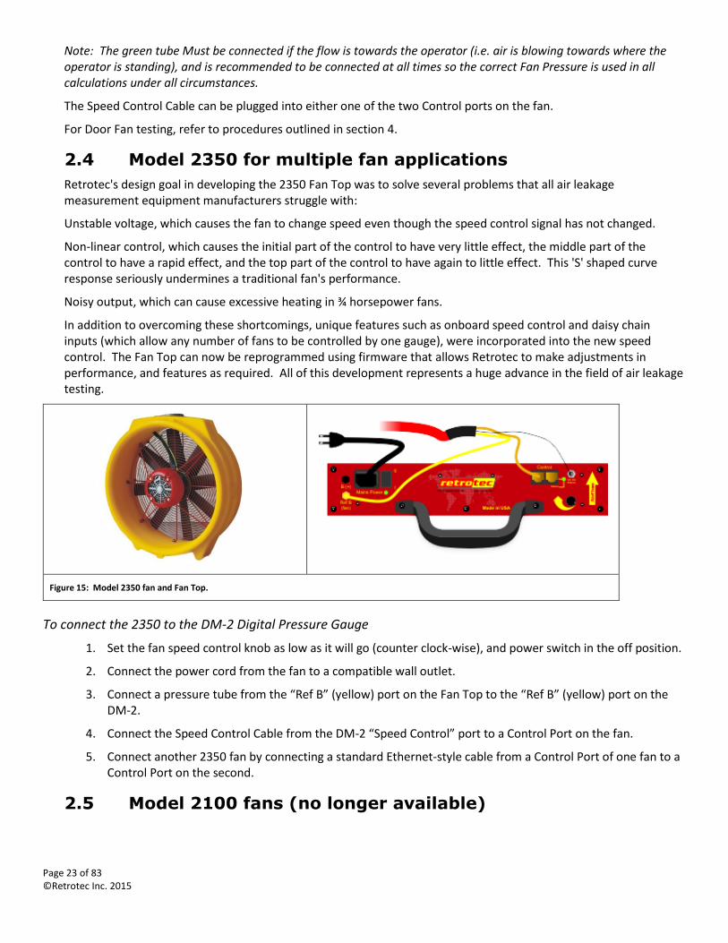
2.4 Model 2350 for multiple fan applications
Retrotec's design goal in developing the 2350 Fan Top was to solve several problems that all air leakage measurement equipment manufacturers struggle with:
Unstable voltage, which causes the fan to change speed even though the speed control signal has not changed.
Non-linear control, which causes the initial part of the control to have very little effect, the middle part of the control to have a rapid effect, and the top part of the control to have again to little effect. This 'S' shaped curve response seriously undermines a traditional fan's performance.
Noisy output, which can cause excessive heating in ¾ horsepower fans.
In addition to overcoming these shortcomings, unique features such as onboard speed control and daisy chain inputs (which allow any number of fans to be controlled by one gauge), were incorporated into the new speed control. The Fan Top can now be reprogrammed using firmware that allows Retrotec to make adjustments in performance, and features as required. All of this development represents a huge advance in the field of air leakage testing.
Figure 15: Model 2350 fan and Fan Top.
To connect the 2350 to the DM-2 Digital Pressure Gauge
1. Set the fan speed control knob as low as it will go (counter clock-wise), and power switch in the off position.
2. Connect the power cord from the fan to a compatible wall outlet.
3. Connect a pressure tube from the “Ref B” (yellow) port on the Fan Top to the “Ref B” (yellow) port on the DM-2.
4. Connect the Speed Control Cable from the DM-2 “Speed Control” port to a Control Port on the fan.
5. Connect another 2350 fan by connecting a standard Ethernet-style cable from a Control Port of one fan to a Control Port on the second.
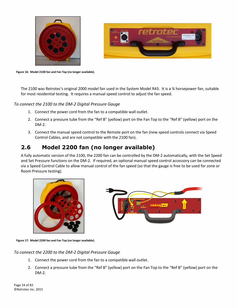
2.5 Model 2100 fans (no longer available)
Page 24 of 83 ©Retrotec Inc. 2015
Figure 16: Model 2100 fan and Fan Top (no longer available).
The 2100 was Retrotec's original 2000 model fan used in the System Model R43. It is a ¾ horsepower fan, suitable for most residential testing. It requires a manual speed control to adjust the fan speed.
To connect the 2100 to the DM-2 Digital Pressure Gauge
1. Connect the power cord from the fan to a compatible wall outlet.
2. Connect a pressure tube from the “Ref B” (yellow) port on the Fan Top to the “Ref B” (yellow) port on the DM-2.
3. Connect the manual speed control to the Remote port on the fan (new speed controls connect via Speed Control Cables, and are not compatible with the 2100 fan).
2.6 Model 2200 fan (no longer available)
A fully automatic version of the 2100, the 2200 fan can be controlled by the DM-2 automatically, with the Set Speed and Set Pressure functions on the DM-2. If required, an optional manual speed control accessory can be connected via a Speed Control Cable to allow manual control of the fan speed (so that the gauge is free to be used for zone or Room Pressure testing).
Figure 17: Model 2200 fan and Fan Top (no longer available).
To connect the 2200 to the DM-2 Digital Pressure Gauge
1. Connect the power cord from the fan to a compatible wall outlet.
2. Connect a pressure tube from the “Ref B” (yellow) port on the Fan Top to the “Ref B” (yellow) port on the DM-2.
Page 25 of 83 ©Retrotec Inc. 2015
3. Connect the Control Cable from the DM-2 to the Control Port on the Fan Top.
4. If required, connect a Manual Speed Control to the Control Port on the Fan Top with a Speed Control Cable.
Page 26 of 83 ©Retrotec Inc. 2015
3. Choose a Door Panel based on size of door and fans
Retrotec offers three types of Door Panels. The most common style of Door Panel is a Cloth Door Panel on an Aluminum Frame. Modular panels (or Modular Door Panels) are a set of solid panels that expand to fit most doors, and offer a quick setup or take down option that is professional looking and easy to carry. For large buildings, three fans can be mounted in one Three-Fan Panel, to maximize the airflow pushed through one doorway.
Only 2000 and 3000 Series fans will fit properly in the Hard Modular Panel but they must have a label on the fan stating it will fit properly in the Hard Panel.
3.1 Cloth Door Panel with Aluminum Frame
A Cloth Door Panel with aluminum frame is standard with the Q46, Q56, and 1000 Door Fan systems. If purchased separately, the Cloth Door Panel can be used with most Retrotec fans.
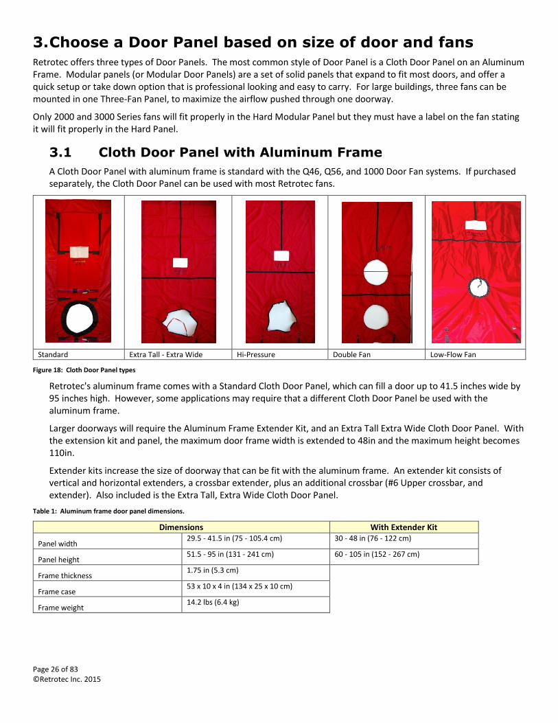
Standard Extra Tall - Extra Wide Hi-Pressure Double Fan Low-Flow Fan
Figure 18: Cloth Door Panel types
Retrotec's aluminum frame comes with a Standard Cloth Door Panel, which can fill a door up to 41.5 inches wide by 95 inches high. However, some applications may require that a different Cloth Door Panel be used with the aluminum frame.
Larger doorways will require the Aluminum Frame Extender Kit, and an Extra Tall Extra Wide Cloth Door Panel. With the extension kit and panel, the maximum door frame width is extended to 48in and the maximum height becomes 110in.
Extender kits increase the size of doorway that can be fit with the aluminum frame. An extender kit consists of vertical and horizontal extenders, a crossbar extender, plus an additional crossbar (#6 Upper crossbar, and extender). Also included is the Extra Tall, Extra Wide Cloth Door Panel.
Table 1: Aluminum frame door panel dimensions.
Dimensions With Extender Kit
Panel width 29.5 - 41.5 in (75 - 105.4 cm) 30 - 48 in (76 - 122 cm)
Panel height 51.5 - 95 in (131 - 241 cm) 60 - 105 in (152 - 267 cm)
Frame thickness 1.75 in (5.3 cm)
Frame case 53 x 10 x 4 in (134 x 25 x 10 cm)
Frame weight 14.2 lbs (6.4 kg)
Page 27 of 83 ©Retrotec Inc. 2015
A Hi-Pressure Cloth Door Panel is required if testing is expected to exceed 150 Pa (rated for tests at pressures up to 300 Pa). The Hi-Pressure cloth includes additional security straps to hold the fan in place. Adding an additional crossbar is also recommended for high-pressure tests.
Two fans can also be mounted in a single aluminum frame with the addition of a second crossbar and a Double Fan Cloth Door Panel.
A Low-Flow Fan Cloth Door Panel is used to test tight enclosures with a Model 200 fan.
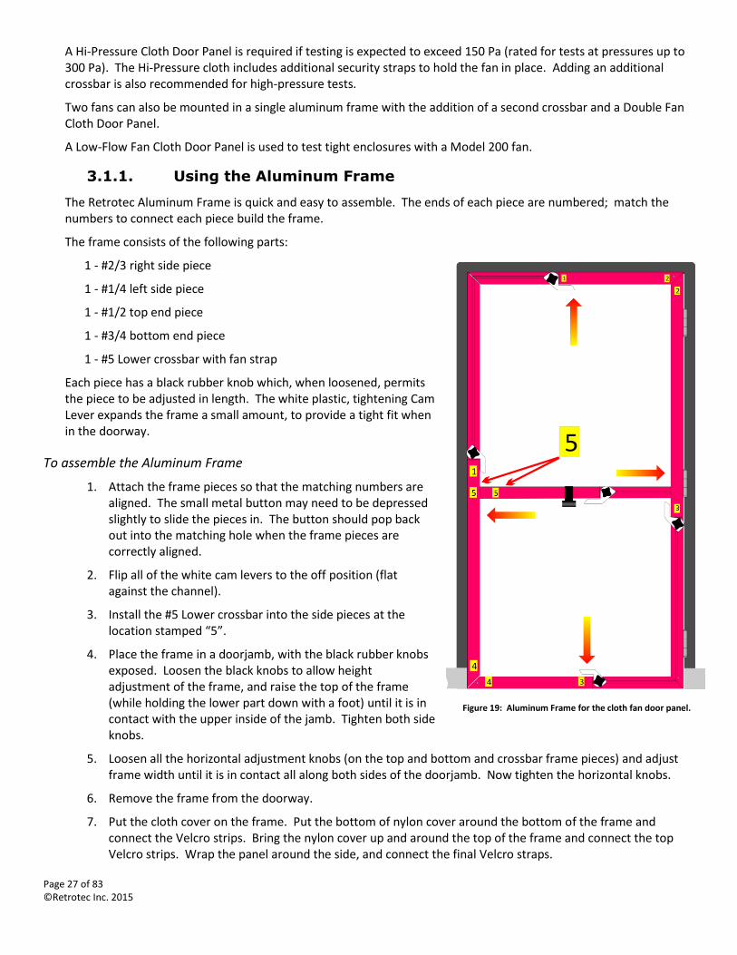
3.1.1. Using the Aluminum Frame
The Retrotec Aluminum Frame is quick and easy to assemble. The ends of each piece are numbered; match the numbers to connect each piece build the frame.
The frame consists of the following parts:
1 - #2/3 right side piece
1 - #1/4 left side piece
1 - #1/2 top end piece
1 - #3/4 bottom end piece
1 - #5 Lower crossbar with fan strap
Each piece has a black rubber knob which, when loosened, permits the piece to be adjusted in length. The white plastic, tightening Cam Lever expands the frame a small amount, to provide a tight fit when in the doorway.
To assemble the Aluminum Frame
1. Attach the frame pieces so that the matching numbers are aligned. The small metal button may need to be depressed slightly to slide the pieces in. The button should pop back out into the matching hole when the frame pieces are correctly aligned.
2. Flip all of the white cam levers to the off position (flat against the channel).
3. Install the #5 Lower crossbar into the side pieces at the location stamped “5”.
4. Place the frame in a doorjamb, with the black rubber knobs exposed. Loosen the black knobs to allow height adjustment of the frame, and raise the top of the frame (while holding the lower part down with a foot) until it is in contact with the upper inside of the jamb. Tighten both side knobs.
5. Loosen all the horizontal adjustment knobs (on the top and bottom and crossbar frame pieces) and adjust frame width until it is in contact all along both sides of the doorjamb. Now tighten the horizontal knobs.
6. Remove the frame from the doorway.
7. Put the cloth cover on the frame. Put the bottom of nylon cover around the bottom of the frame and connect the Velcro strips. Bring the nylon cover up and around the top of the frame and connect the top Velcro strips. Wrap the panel around the side, and connect the final Velcro straps.
Figure 19: Aluminum Frame for the cloth fan door panel.
Page 28 of 83 ©Retrotec Inc. 2015
8. Put the covered frame back in the door opening. Turn all five of the white plastic cam levers to the “expand” position (away from side of channel) to lock it into place.
9. Ensure that the panel is solidly anchored in position. If it needs to be tighter, release the cam levers one at a time, loosen the knob, push the frame into position, tighten the knob, and re-actuate the cam lever.
To remove the frame
1. Release all five white cam levers. Pull the frame from the doorway. It may be necessary to loosen some of the black knobs if the frame was secured tightly in the doorway.
2. Lay the frame flat on the ground, a lean it against a wall.
3. Remove the cloth, and fold it for easy packing.
4. Loosen the black knobs and collapse the frame to its smallest size. The frame can be transported in this fashion, partially assembled, by re-tightening all of the knobs.
5. To disconnect the frame, push the metal button in while pulling the frame pieces apart.
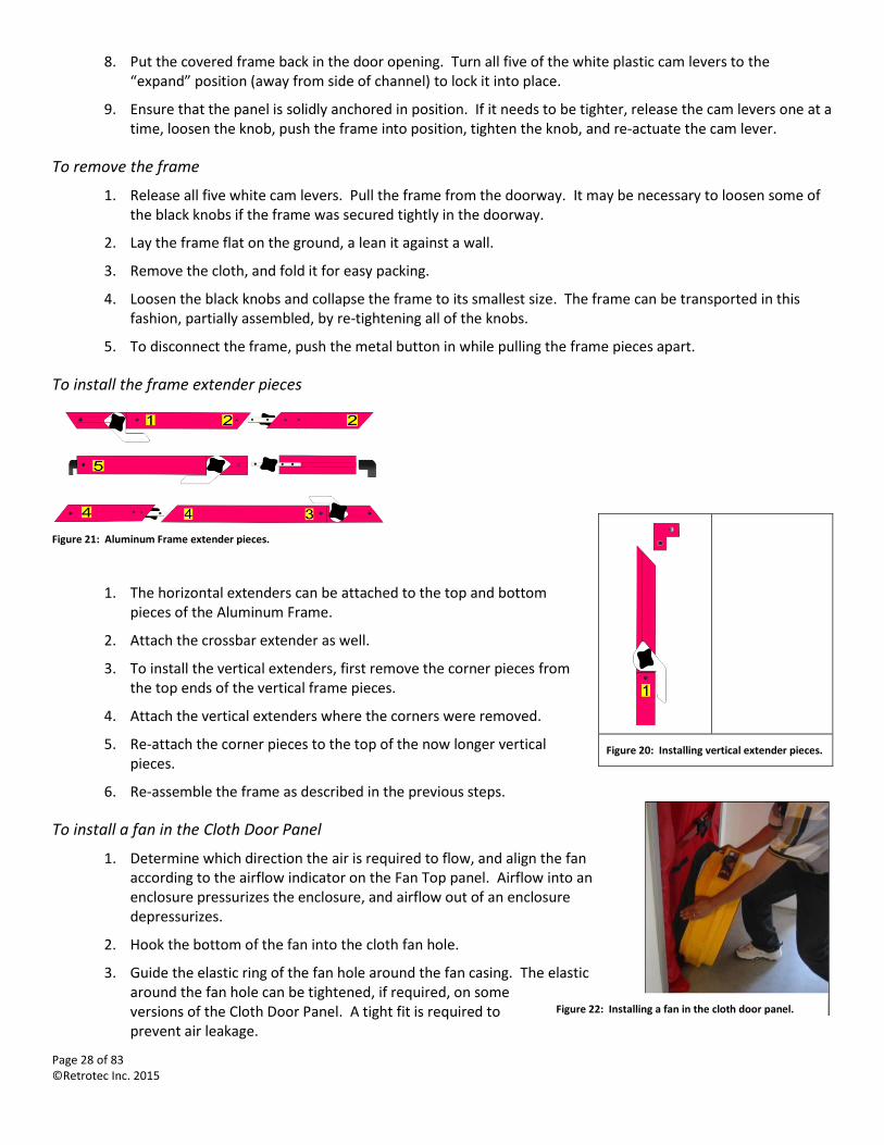
To install the frame extender pieces
Figure 21: Aluminum Frame extender pieces.
1. The horizontal extenders can be attached to the top and bottom pieces of the Aluminum Frame.
2. Attach the crossbar extender as well.
3. To install the vertical extenders, first remove the corner pieces from the top ends of the vertical frame pieces.
4. Attach the vertical extenders where the corners were removed.
5. Re-attach the corner pieces to the top of the now longer vertical pieces.
6. Re-assemble the frame as described in the previous steps.
To install a fan in the Cloth Door Panel
1. Determine which direction the air is required to flow, and align the fan according to the airflow indicator on the Fan Top panel. Airflow into an enclosure pressurizes the enclosure, and airflow out of an enclosure depressurizes.
2. Hook the bottom of the fan into the cloth fan hole.
3. Guide the elastic ring of the fan hole around the fan casing. The elastic around the fan hole can be tightened, if required, on some versions of the Cloth Door Panel. A tight fit is required to prevent air leakage.
Figure 20: Installing vertical extender pieces.
Figure 22: Installing a fan in the cloth door panel.
Page 29 of 83 ©Retrotec Inc. 2015
4. Use the Velcro fan strap on the horizontal crossbar to hold the fan in place. The elastic should not be supporting the weight of the fan.
5. Double-check that the fan airflow is in the correct direction. It will be much harder to switch the fan around once all of the equipment has been connected.
3.1.2. Available Aluminum Frame Part Replacements
It is possible to replace damaged or broken parts of the Aluminum Frame. The following pieces can be replaced:
Cam Levers
Knob
Channel Guides
Corner Block
Expander Block
Weather Strip (rubber part around outside edge)
To order replacement parts, reference the part number in Appendix C.
3.2 Modular Hard Sided Door Panels
A Modular Door Panel is standard with two Door Fan systems: models Q56 and Q5E (see Appendix E for conversion of the old model names to the new ones). If purchased separately, the Modular Door Panel can be used with most Retrotec 2000 and 3300 fans. A special adaptor plate is also available to incorporate Retrotec’s low-flow (DucTester) fans for use with the modular panel.
The modular panel consists of the following parts:
1 x Fan Panel with fan strap
1 x Large-X panel
1 x XY panel
2 x Fan Panel fill sheets (one large, one small)
Additional panels, including a Small-X panel, can be purchased to increase the maximum doorway height that the modular panel is capable of filling.
Overall outside dimensions (OD) for the Modular panels:
Model: PN201
Type of Panel: Hard Panel (Single Fan)
Width (min/max): 32” – 48.75” (81 - 124 cm)
Height (min/max): 76.5” - 87” (194 - 221 cm)
Figure 23: Modular door panel set.
Page 30 of 83 ©Retrotec Inc. 2015
Panel Case (included): 31” x 30” x 7” (79 x 76 x 18 cm)
PN210R Large X-Panel: 27 ¾”H x 29 5/8”W closed, 51”W open
PN211 XY Panel: 19 ½”H x 29 5/8”W closed, 52”W x 30” open
PN207 Large Fill-in Sheet for Fan Panel: 27”H x 17 ½”W OD
PN208 Small Fill-in Sheet for Fan Panel: 26”H x 4 ½”W OD
A Field Verification Plate and a Blanking Plate are available for insertion in the holes of the Modular Door Panel, to run a verification of the calibration of the system and cover any non-needed holes in Fan Panels. See details in Appendix C.
A Weather Strip replacement kit is also available.
3.2.1. Modular Door Panel Instructions
For detailed instructions on installing the Modular Door Panel, see the Modular Door Panel Quick Guide.
To install the Modular Door Panels
1. Unpack the panels. The Fan Panel is installed first. Place it in the doorway, touching the ground. All panels should expand towards the door hinges. The panels can be expanded by pulling the yellow cords tight, and then securing the cord on the cleat. Do not secure the yellow cords on the Velcro, to hold the straps tight. The Velcro is only meant to hold the straps against the panels. Attach the fan strap.
2. Attach a Fan Panel fill sheet to cover any gap that is created by expanding the Fan Panel.
3. Install the Large-X panel, so that it is touching the top of the door frame. Expand it so that it is held in place securely.
4. If required, install a Small-X panel just below the Large-X panel.
5. Install the XY panel. Expand it both vertically and horizontally to completely seal the doorway.
6. Grill mask can be used to seal any small gaps that remain.
7. A second Fan Panel can be substituted for the Large-X panel if required. However, it should be placed directly above the first Fan Panel, with the Small-X or XY panel being used at the top of the doorway instead.
To install a fan in a Modular Door Panel
Figure 24: Modular door panel set installed.
Page 31 of 83 ©Retrotec Inc. 2015
1. Determine which direction of airflow is required and align the fan according to the airflow indicator on the top Fan Panel. Airflow into an enclosure pressurizes the enclosure, and airflow out of an enclosure depressurizes.
2. Insert the bottom of the fan into the Fan Panel.
3. Align the notches on the fan with the corresponding notches on the Fan Panel.
4. Push the fan into the hole, and rotate the fan slightly to secure it in the panel.
5. Hook the fan strap over the edge of the fan shell to hold it in place.
6. Double-check that the fan airflow is in the correct direction. It will be much harder to switch the fan around once all of the equipment has been connected.
3.3 Triple-Fan Molded Panel Set for multiple fan tests
The Triple-Fan Molded Panel Set is a specially designed folding panel which supports up to three 3000 Retrotec fans in one doorway. The panel is included with the QMG system, or can be ordered separately. Blanking plates are included with the Molded Panel Set, so that it can be used with fewer than three fans if required.
3.3.1. Using the Triple-Fan Molded Panel Set
For detailed instructions on using the Triple-Fan Molded Panel Set, see the QMG Quick Guide.
To install the Triple-Fan Molded Panel:
1. Unfold the panel, and lock the four butterfly latches.
2. Place the Fan Panel against the doorway, on the opposite side of the door frame from the door.
3. Secure the top corner of the panel, nearest the hinges, by placing the circular retention strap anchor behind the door/door frame gap.
4. Slide two retention straps over each cross brace, and insert the narrow end of the cross braces into the door/door frame gap, so that it runs parallel to the fold joints of the Three Fan Panel. Secure the cross braces to the Door Panel using the retention straps. The locking collars should be used to keep the retention straps from sliding around the cross braces.
5. Use the corner brace to secure the remaining top corner, by placing it diagonally across the door frame, and attaching a retention strap to the Door Panel.
6. Attach a fan strap for each fan being used.
7. Use grill mask to seal any gap left between the top of the panel and the door frame.
Figure 25: Installing a fan in a modular door panel set.
Figure 26: Lock and butterfly latch for the triple-fan moulded panel set.
Figure 27: Cross brace for the triple-fan moulded panel set.
Page 32 of 83 ©Retrotec Inc. 2015
Space permitting, two of the Three-Fan Panels can be joined together to mount six fans together. Use the connector plate to connect the two panels, with the fan holes oriented towards the middle. In this situation, it is unlikely that the cross braces can be used. Use the retention straps and secure the panels using the door/door frame gap where possible.
3.4 Compensating for Panel leakage
Modular Panels are designed to be placed into doors that are not well sealed. The panel leakage for the Modular Panel is about 14 square inches compared to about 3 square inches for the Aluminum Frame and Cloth and around 1 square inch of leakage for the upgraded Aluminum Frame with snap together corners. These three panels represent three typical doorways: a) Poorly weather-stripped which would have an approximate 1/16 inch gap which equals about 14 square inches leakage; b) A well weather-stripped and adjusted door would be around 3 square inches or leakage; c) A super tight door could be as tight as 1 square inch of leakage and can even have less.
One rule of thumb is that all standards require the blower door panel to be leakier and never tighter than the existing door. The Modular Panel qualifies here. It is likely that the Aluminum Frame and Cloth are tighter than the existing door. In either case, if the door panel leakage is 10% of the total, then further investigation is needed.
Modular Panels:
1000 CFM at 50 Pa, no attention needs to be paid to the door panel leakage. If the flow rate is under that you might want to measure the panel tightness compared to the door tightness and subtract any excess from the readings. Or, if the panel is tighter than the door, you will have to add it.
Example; 500 CFM at 50 Pa for the enclosure. Door is closed over top of the panel with the red tube in the gap and leakage measured at 50 Pa of 140 CFM. The door is then taped shut to measure panel leakage which is 80 CFM at 50 Pa. The Door thus leaks 140-80=60 CFM. Correction to test result is then: 500-80+60= 480 CFM.
Aluminum Frame and Cloth:
220 CFM at 50 Pa, no attention needs to be paid to the door panel leakage.
Aluminum Frame with upgraded snap together corners and Cloth:
70 CFM at 50 Pa, no attention needs to be paid to the door panel leakage. If the flow rate is under that you should measure the panel tightness compared to the door tightness and subtract any excess from the readings. Or, if the panel is tighter than the door, you will have to add it which is more common and shown in the following example:
Example: 50 CFM at 50 Pa for the enclosure. Door is closed over top of the panel with the red tube in the gap and leakage measured at 50 Pa of 8 CFM. The door is then taped shut to measure panel leakage which is 3 CFM at 50 Pa. The Door then leaks 8-3= 5 CFM. Correction to test result is thus: 50-3+5= 52 CFM.
These tests are rarely done but testers should learn how leaky their panels are in advance of any test they may do. Retrotec has performed this test in nuclear power plants where every part of the test needed to be documented including panel leaks. Learning how much your panels leak will be a useful tool to determine how they might be affecting your results. For example, when Modular Panels are used to measure flows well in excess of 2000 CFM, the panel leakage is irrelevant, but in tight rooms it could make the difference between pass or fail. One has to determine then if the door leakage may be a major part of the total and cannot just be deducted. Similarly, if you are using the new tight Aluminum Frame with square snap together corners, your readings might be low.
Page 33 of 83 ©Retrotec Inc. 2015
4. Conduct a Test
4.1 Observe house to avoid problems during testing
4.1.1. Ashes and other materials can blow into house
Depressurizing a house causes air to be sucked in from openings. This can be especially troublesome in a fireplace. If proper care isn't taken to cover exposed, loose ashes, prior to beginning a test, the air flowing in through the chimney can blow ashes out of the fireplace.
Likewise, other loose household materials can be moved around by airflow, especially if the materials are located close to a major leak or the fan itself. It's very easy to blow loose papers, and other small objects around a house if due care isn't taken to secure them before beginning testing.
4.1.2. Doors can slam shut
If a door suddenly shuts while using a Door Fan, the sudden change in pressure can be enough to damage an enclosure or pop the fan out of the panel. Be sure to secure doors in the correct position, prior to starting the fan. If a door shuts during testing, and it goes unnoticed, the accuracy of the test will be affected, because not all of the building will be included in the test, as the area behind the closed door is treated as unconditioned space.
4.2 Select a Location
The first step in any test is to select a doorway, and install the Door Panel.
An exterior doorway in a large open room is best. Avoid doorways that have walls, stairs, or other obstructions nearby. These will restrict airflow, and can lead to inaccurate results.
If the exterior doorway opens to an enclosed porch, garage or other area, open doors or windows to ensure the enclosed area is open to the outside.
4.3 Where to place the exterior Pressure pickup tube
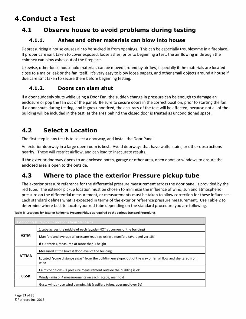
The exterior pressure reference for the differential pressure measurement across the door panel is provided by the red tube. The exterior pickup location must be chosen to minimize the influence of wind, sun and atmospheric pressure on the differential measurement, or measurements must be taken to allow correction for these influences. Each standard defines what is expected in terms of the exterior reference pressure measurement. Use Table 2 to determine where best to locate your red tube depending on the standard procedure you are following.
Table 2: Locations for Exterior Reference Pressure Pickup as required by the various Standard Procedures
Exterior pressure pick-up locations from Standards
ASTM
1 tube across the middle of each façade (NOT at corners of the building)
Manifold and average all pressure readings using a manifold (averaged ver 10s)
If > 3 stories, measured at more than 1 height
ATTMA Measured at the lowest floor level of the building
Located "some distance away" from the building envelope, out of the way of fan airflow and sheltered from wind
CGSB
Calm conditions - 1 pressure measurement outside the building is ok
Windy - min of 4 measurements on each façade, manifold
Gusty winds - use wind damping kit (capillary tubes, averaged over 5s)
Page 34 of 83 ©Retrotec Inc. 2015
EN13829-FR
Measure at the bottom floor level, but if tall building, measure at the top as well
Keep exterior pressure taps out of the sun, and fitted to a T-pipe or connected to a perforated box to protect from wind
USACE Min 1 exterior pressure tap required, but if bias pressures high, use more
Interior pressure gauge references tied together in a manifold to read 1 pressure reading
4.4 Determine if corrections for temperature difference are required
In conditions where the interior and exterior temperature differential varies greatly, the fan measurements can be less accurate. In a depressurization test, the Door Fan system measures the fan flow out of the building. However, the measurement is meant to reflect the air infiltrating into the house through all the leaks. When there is a temperature difference, the air density changes, and the leaks will not exactly equal the measured fan flow. In extreme conditions, this difference can be as much as 10%.
Each Standard that users comply with will require different corrections. FanTestic software will manage these corrections when calculating results after you enter the data.
4.5 Install the Door Fan for Depressurization test
A building depressurization test (blowing air out of the building) is the most common way of conducting a Door Fan measurement. This direction of testing has a number of advantages, but the primary reason is that back-draft dampers in exhaust fans and dryers are pulled closed during depressurization. Since these dampers are usually shut, leakage from them can be left out of calculations resulting from a typical Door Fan test.
The building's door frame can be used to help secure the fan and panel in place. For a depressurization test, install the Door Panel on the inside of the door, the door frame will then help keep the panel in place when the negative pressure tries to pull it through the door way.
To install the Door Fan
1. Install the Door Panel by following either the cloth or modular panel setup instructions.
1. Run the red pressure tube through the hole in the Door Panel to the outdoors. Make sure the end of the tube is not in the path of the fan's airflow.
2. Install the fan in the Door Panel. Make sure the flow direction is out of the building.
3. Connect the digital gauge to the fan. Tubing for a Retrotec DM-2 is connected the same way for both pressurization and depressurization.
4. Connect the fan to a suitable wall outlet for power.
4.6 Set up the Gauge for the Appropriate Test
Look at the Quick Guides or Manual for the DM-2 or the DM32, depending on which gauge you are using.
4.7 Connect a Fan to the gauge (DM-2 or DM32)
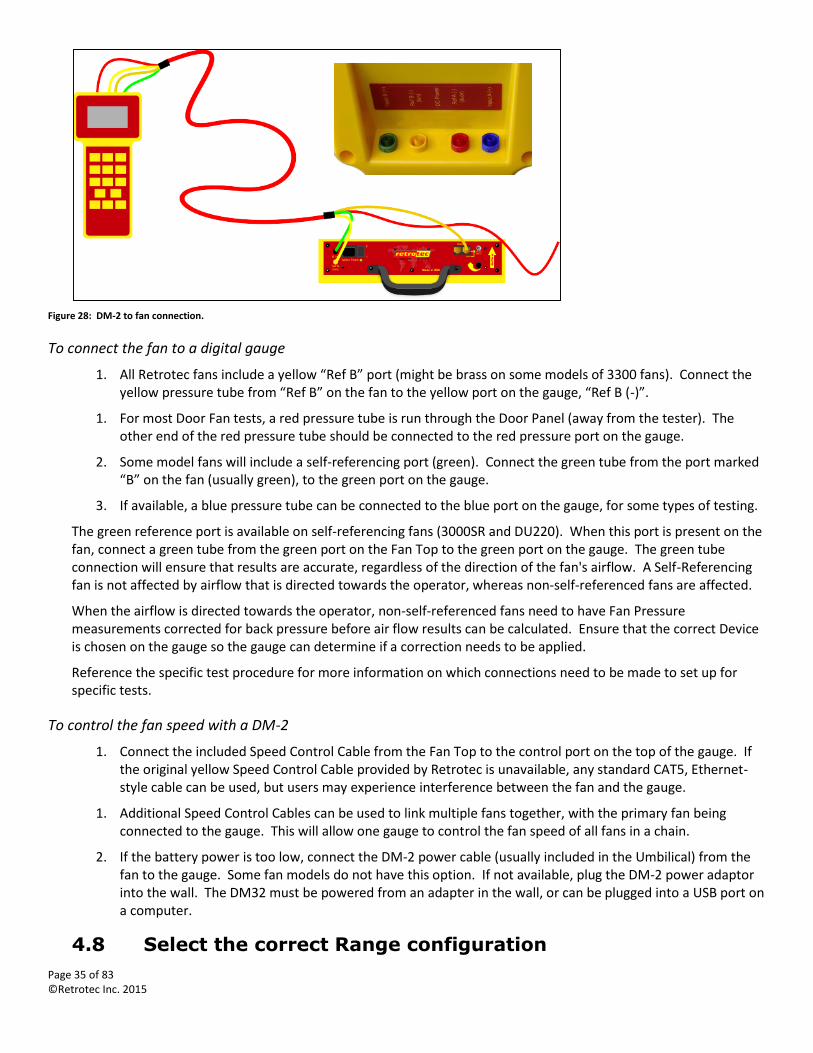
It's very simple to connect a Retrotec fan to the Retrotec digital gauges. Depending on which model fan is in use, there will be some combination of red, blue, green, and yellow pressure tubes included. These tubes connect to their corresponding color coded ports on the back of the Retrotec gauge. Color coding is the same on both the DM-2 and the DM32. The Speed Control Cable connects to the port marked “Speed Control” on the DM-2 or to the port marked “Control” on the top of DM32.
Page 35 of 83 ©Retrotec Inc. 2015
Figure 28: DM-2 to fan connection.
To connect the fan to a digital gauge
1. All Retrotec fans include a yellow “Ref B” port (might be brass on some models of 3300 fans). Connect the yellow pressure tube from “Ref B” on the fan to the yellow port on the gauge, “Ref B (-)”.
1. For most Door Fan tests, a red pressure tube is run through the Door Panel (away from the tester). The other end of the red pressure tube should be connected to the red pressure port on the gauge.
2. Some model fans will include a self-referencing port (green). Connect the green tube from the port marked “B” on the fan (usually green), to the green port on the gauge.
3. If available, a blue pressure tube can be connected to the blue port on the gauge, for some types of testing.
The green reference port is available on self-referencing fans (3000SR and DU220). When this port is present on the fan, connect a green tube from the green port on the Fan Top to the green port on the gauge. The green tube connection will ensure that results are accurate, regardless of the direction of the fan's airflow. A Self-Referencing fan is not affected by airflow that is directed towards the operator, whereas non-self-referenced fans are affected.
When the airflow is directed towards the operator, non-self-referenced fans need to have Fan Pressure measurements corrected for back pressure before air flow results can be calculated. Ensure that the correct Device is chosen on the gauge so the gauge can determine if a correction needs to be applied.
Reference the specific test procedure for more information on which connections need to be made to set up for specific tests.
To control the fan speed with a DM-2
1. Connect the included Speed Control Cable from the Fan Top to the control port on the top of the gauge. If the original yellow Speed Control Cable provided by Retrotec is unavailable, any standard CAT5, Ethernet-style cable can be used, but users may experience interference between the fan and the gauge.
1. Additional Speed Control Cables can be used to link multiple fans together, with the primary fan being connected to the gauge. This will allow one gauge to control the fan speed of all fans in a chain.
2. If the battery power is too low, connect the DM-2 power cable (usually included in the Umbilical) from the fan to the gauge. Some fan models do not have this option. If not available, plug the DM-2 power adaptor into the wall. The DM32 must be powered from an adapter in the wall, or can be plugged into a USB port on a computer.
4.8 Select the correct Range configuration
Page 36 of 83 ©Retrotec Inc. 2015
All Retrotec fans have multiple Range configurations. The Range configurations are used to affect the airflow and fan pressure through the fan. During testing, it is necessary to select the correct Range Configuration to achieve measurable and accurate results.
Each Retrotec DucTester includes three ranges, and each Door Fan comes with 11 Range Configurations for the greatest possible accuracy and versatility.
Selecting a Range configuration is based upon the air flow that is required to achieve the test pressure in the enclosure. A general rule of thumb is to select a Range configuration so that the Fan Pressure is twice (or more) the desired test pressure in the enclosure.
Testing should always be done with the most restrictive Range Configuration on the fan as possible for the following reasons:
1. Accuracy increases as Fan Pressure increases
2. High Fan Pressure results in high fan speed, which aids in cooling the fan
3. When conducting multi-point tests, starting with a restrictive Range Configuration eliminates the need to change the Range Configuration during the test.
Note: In European countries where a 50 Hz power system is used, Range Configuration selection becomes more critical because the fans will run 20% slower. Therefore, there is not as much difference between minimum and maximum flow on any given Range Configuration.
4.9 Determine which Range to use on a Door Fan
1. Attach Range Ring A and B.
2. Set the gauge to Range Configuration B
3. Adjust the fan speed until the desired Room Pressure is reached.
If using the DM-2 digital gauge:
4. If “TOO LOW” is shown on Channel B of the DM-2, attach the C8 Range Plate. Restrict the flow further, until the gauge is able to measure a pressure.
5. Press [Range Config] until the correct “Range Config” is displayed on the DM-2 screen.
Or
4. If the desired Room Pressure cannot be reached, take Range Plates or Range Rings off.
5. Press [Range Config] until the correct “Range Config” is displayed on the DM-2 screen.
If using analog gauges:
4. Select a Range Configuration so that the Fan Pressure is twice (or more) the Room Pressure.
4.10 Cannot reach required pressure?
If the enclosure to be measured has an excessive amount of leakage, to the point where a single fan unit on the Open Range and at maximum speed, cannot reach the required pressure, try one of the following solutions:
1. Use a second (additional) fan to produce more flow. The combined flow readings can be used to get the total amount of airflow required to achieve the induced pressure. Do not add Fan Pressure readings (PrB), they are not cumulative. Fan Pressure must be converted to flow in CFM (or some other units) and then the resulting flows can be added together.
Page 37 of 83 ©Retrotec Inc. 2015
2. Test at the highest pressure that can be reached, and use the @ Pressure key to extrapolate what the flow would be at the desired pressure. Check that the Standard you have to comply with allows this.
3. Seal leaks prior to testing. This can include ensuring that all dampers, windows, and doors are closed, in addition to sealing leaks and holes. This may reduce the leakage enough that the desired test pressure can be reached.
4.11 Choose either a Single or Multi- Point Test Procedure
There are two common Door Fan test procedures available for testing the air leakage of a building: a single-point test, and a multi-point test.
A single-point test establishes a 50 Pa test pressure in the building; results come from measuring the fan flow required to maintain the pressure imbalance. This is a quick and simple way of measuring airtightness, and by using the Fan Pressure measurement, simple results such as the size of the total leakage can be determined.
A multi-point test requires that the user collect flow data for several different induced target pressure points.
4.12 Taking Manual Single Point Readings
This section is written for circumstances where results are read directly from the gauge. They may possibly be recorded manually also but not necessarily.
4.12.1. Measure the Baseline Pressure before turning the fan on
Commonly, test procedures require that the pre-existing pressure across the building be measured and that value be subtracted from the test pressure to uncover how much change occurred in the building pressure due to Test Fan operation. Baseline is sometimes called Bias Pressure or even Static Pressure but we will primarily use “Baseline” here.
The length of time to take the Baseline varies from Standard to Standard or the amount of time needed may not be mentioned. Ten seconds is a reasonable amount of time to spend on Baseline Capture on a calm day but as the wind increases or the Baseline fluctuates at all, this should be increased. To determine the effects of wind, set your gauge to 1 second averaging and if the pressure fluctuation is above 1 Pa, take the Baseline for 30 seconds. If the pressure fluctuation is above 2 Pa, take the Baseline for 120 seconds. If the fluctuation is still above 1 Pa after 120 seconds, continue to acquire the Baseline until the average fluctuates less than 1 Pa.
Save this Baseline once you are satisfied with it. The value stored and displayed on your gauge will be deducted from all future readings so make sure you eliminate the stored Baseline before running your gauge in another application.
4.12.2. Adjust your test fan manually
Adjust the Blower Door (also called Test Fan or Door Fan) fan speed manually using the control knob to the required test pressure that will often be 50 Pa. Change the Range if you cannot achieve the test pressure or if no flow reading appears on Channel B. With the gauge still set to a Time Averaging of 1 second, you may take a reading but chances are you’ll be over or under the required test pressure or the result will fluctuate on either side. To get the exact reading at your test pressure, enter Set Pressure, 50 Pa for example, then press the “@” Key to get results at exactly 50 Pa.
To get an even more accurate result and with the fan still running set the Time Averaging to the same amount of time taken to Capture the Baseline. Channel B will stay blank while the average is being taken after which the result will be displayed. If the fan does not continue to run during this step, and the longer Time Averaging is set, then you must wait until the fan comes up to speed, then wait the time for the Averaging before taking a reading because the gauge will be averaging for the entire time and will be averaging in values below the test pressure. As a rule of thumb, always wait double the Time Average setting before taking readings.
Page 38 of 83 ©Retrotec Inc. 2015
On the DM32, tap Channel A to activate the Hold feature so the readings don’t change while you’re writing them down.
4.12.3. Adjust your test fan using Set Pressure
Warning: using this automated procedure will allow the fan to run up to full speed should a door be opened during the test, causing damage when it is closed. If in doubt, use the previous method.
With the gauge still set to a Time Averaging of 1 second, enter Set Pressure, 50 Pa for example. Change the Range if you cannot achieve the test pressure or if no flow reading appears on Channel B. Once you get within 10% of your desired test pressure, press the “@” Key to get results at exactly 50 Pa and with the fan still running set the Time Averaging to the same amount of time taken to Capture the Baseline. The display will go blank for that same time period after which you can read your result off the display and change units without affecting the readings. You can also HOLD the display, shut the fan down and change units.
4.13 Taking Manual Multi-Point Readings for FanTestic Software
In general, the multi-point test requires that the user collect pressures for a pre-test baseline, collect flows for a set of target pressures (in one or both pressurize and depressurize directions), and sometimes to collect pressures afterwards for a post-test baseline. The collected data is entered into software such as FanTestic in order to generate results from the test which indicate the amount of leakage in the tested enclosure.
Each Standard that users comply with for collecting the data and generating the results have different sets of target pressures (based on different required maximum and minimum target pressures and number of different targets), different requirements for the baseline measurements, and different ways of calculating the results.
The method described in this section is recommended to achieve the most accurate and repeatable test results. Skipping or reducing any of the steps may allow your test results to pass, but this does not mean that an accurate test has been performed.
In order to produce the most Retrotec has included factory defaults in FanTestic which recommend the number or baseline and target points for each of its supported standards. Unless these recommendations are followed, tests will not be repeatable and there will not be enough data to determine what went wrong with a particular test. Retrotec will not be able to analyze the test and recommend corrections if these recommendations are not followed.
4.13.1. Decide how many test points to take
Taking an accurate test means that results will be more repeatable. Taking an inaccurate test means that re-tests of the same enclosure may show very different results. Accurate tests results are achieved with more abundant data, taken over a longer time interval. The EN13829 standard, for example, requires only 5 induced target pressure points but this will usually produce non-repeatable results, as the following graphs show.
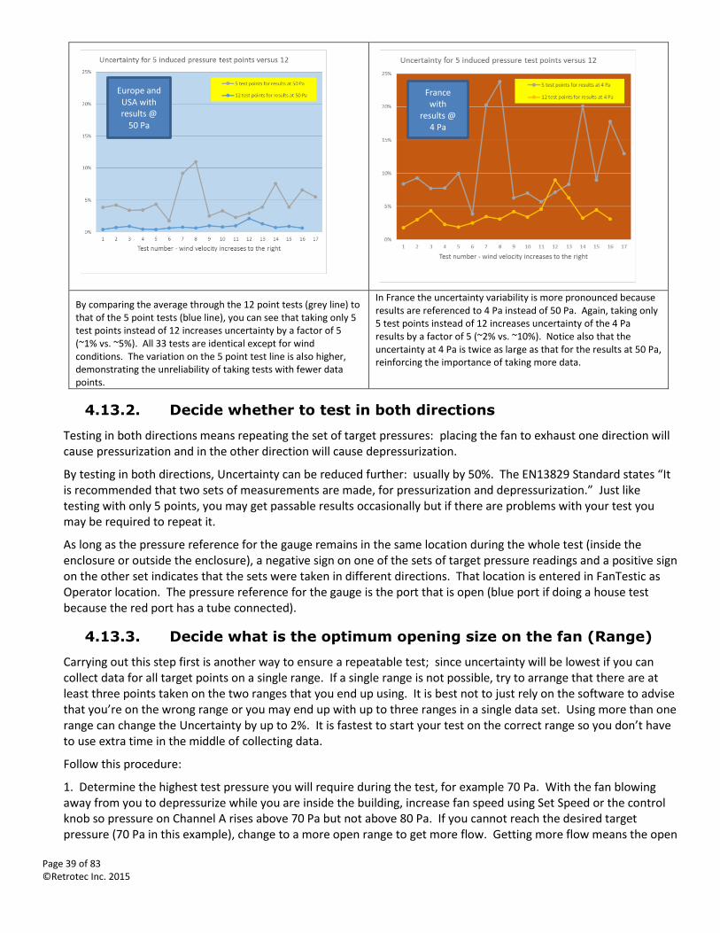
Page 39 of 83 ©Retrotec Inc. 2015
By comparing the average through the 12 point tests (grey line) to that of the 5 point tests (blue line), you can see that taking only 5 test points instead of 12 increases uncertainty by a factor of 5 (~1% vs. ~5%). All 33 tests are identical except for wind conditions. The variation on the 5 point test line is also higher, demonstrating the unreliability of taking tests with fewer data points.
In France the uncertainty variability is more pronounced because results are referenced to 4 Pa instead of 50 Pa. Again, taking only 5 test points instead of 12 increases uncertainty of the 4 Pa results by a factor of 5 (~2% vs. ~10%). Notice also that the uncertainty at 4 Pa is twice as large as that for the results at 50 Pa, reinforcing the importance of taking more data.
4.13.2. Decide whether to test in both directions
Testing in both directions means repeating the set of target pressures: placing the fan to exhaust one direction will cause pressurization and in the other direction will cause depressurization.
By testing in both directions, Uncertainty can be reduced further: usually by 50%. The EN13829 Standard states “It is recommended that two sets of measurements are made, for pressurization and depressurization.” Just like testing with only 5 points, you may get passable results occasionally but if there are problems with your test you may be required to repeat it.
As long as the pressure reference for the gauge remains in the same location during the whole test (inside the enclosure or outside the enclosure), a negative sign on one of the sets of target pressure readings and a positive sign on the other set indicates that the sets were taken in different directions. That location is entered in FanTestic as Operator location. The pressure reference for the gauge is the port that is open (blue port if doing a house test because the red port has a tube connected).
4.13.3. Decide what is the optimum opening size on the fan (Range)
Carrying out this step first is another way to ensure a repeatable test; since uncertainty will be lowest if you can collect data for all target points on a single range. If a single range is not possible, try to arrange that there are at least three points taken on the two ranges that you end up using. It is best not to just rely on the software to advise that you’re on the wrong range or you may end up with up to three ranges in a single data set. Using more than one range can change the Uncertainty by up to 2%. It is fastest to start your test on the correct range so you don’t have to use extra time in the middle of collecting data.
Follow this procedure:
1. Determine the highest test pressure you will require during the test, for example 70 Pa. With the fan blowing away from you to depressurize while you are inside the building, increase fan speed using Set Speed or the control knob so pressure on Channel A rises above 70 Pa but not above 80 Pa. If you cannot reach the desired target pressure (70 Pa in this example), change to a more open range to get more flow. Getting more flow means the open
France with
results @ 4 Pa
Europe and USA with results @
50 Pa
Page 40 of 83 ©Retrotec Inc. 2015
area of the fan inlet must be increased so you are not looking for a higher Fan Pressure but a more open fan. If you can easily achieve 70 Pa, try a less open range that will give less air flow and try again.
2. Determine the lowest test pressure you will require during the test, for example, 15 Pa. Leaving the fan as it was at the end of the previous step, running and achieving the maximum pressure with the most restrictive possible range, decrease fan speed using Set Speed or the control knob so pressure on Channel A falls to just below 15 Pa. There will be times you cannot reach the lowest target pressure (15 Pa in this example). Either you cannot run the fan slowly enough (reach 0% speed before the target pressure reaches 15 Pa), or the flow on Channel B will not show a value (not enough fan pressure is being developed). In either case, you need to change to a more restrictive range to develop more fan pressure. Since you already determined the smallest range that will let you reach the maximum target pressure (in step 1), you now know that you will have to change range once during your data collection.
4.13.4. Measure the Baseline (Zero Flow) Pressure before the test
Commonly, test procedures require that the pre-existing pressure across the building be measured. That value is subtracted from the test pressure to uncover how much change occurred in the building pressure due to Test Fan operation. Baseline is sometimes called Bias Pressure or Zero Flow Pressure or even Static Pressure but we will primarily use “Baseline” here.
Note that there are two main components of Baseline: one is caused by stack pressures and the other by wind. Stack is a building phenomenon which produces a steady pressure and is simply subtracted from the test pressure. Wind may also cause some steady pressure which can be subtracted. However, wind generally also causes a pressure that fluctuates over time. This fluctuation will distort the induced (applied) pressure difference when the Blower Door is collecting data unless the measurement period is long enough to reduce the effect of the fluctuations.
The length of time the Baseline must be taken varies from Standard to Standard but mostly is not specified exactly which is why this guidance is being provided. EN13829 states “over a period of at least 30 seconds” but does not state the required number of test points.
Recommended procedure to take the pre-test Baseline:
When manually entering data into FanTestic, set the Time Averaging on the gauge to 5 seconds for Baseline readings. Start at 5 second averaging for manual readings since it will take you at least this long to write them down anyway. There is a Baseline feature on the gauge but do not use it for this purpose since it was designed for single point readings.
4.13.5. Measure each of the target points required for the test
Use either the fan speed control knob, the gauge Set Speed control, or the gauge Set Pressure control to capture data for each of the target induced pressure points you need for the test.
When manually entering data into FanTestic, set the time averaging on the gauge to at least 20 seconds for induced pressure and flow readings. This must be done in order to compensate for the effects of wind and to ensure that you get an average reading. On windy days you will have to take readings for a longer period of time. To determine if it is windy, set your gauge to 5 second averaging and check if the pressure fluctuation is above 2 Pa. If so, double the time averaging for the induced pressure and flow readings to 40 seconds.
On the DM32, you can tap Channel A to activate the Hold feature so the readings don’t change while you’re writing them down. On the DM-2, press the HOLD key. Write down all your readings.
4.13.5.1. Adjust your test fan using Set Speed
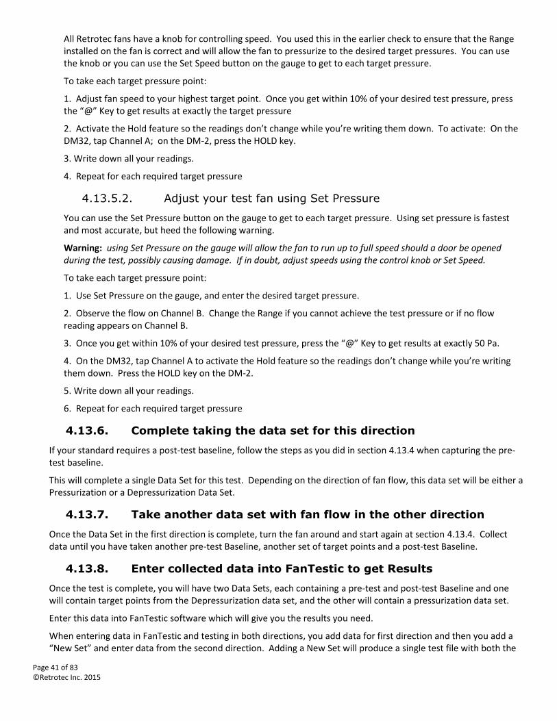
Page 41 of 83 ©Retrotec Inc. 2015
All Retrotec fans have a knob for controlling speed. You used this in the earlier check to ensure that the Range installed on the fan is correct and will allow the fan to pressurize to the desired target pressures. You can use the knob or you can use the Set Speed button on the gauge to get to each target pressure.
To take each target pressure point:
1. Adjust fan speed to your highest target point. Once you get within 10% of your desired test pressure, press the “@” Key to get results at exactly the target pressure
2. Activate the Hold feature so the readings don’t change while you’re writing them down. To activate: On the DM32, tap Channel A; on the DM-2, press the HOLD key.
3. Write down all your readings.
4. Repeat for each required target pressure
4.13.5.2. Adjust your test fan using Set Pressure
You can use the Set Pressure button on the gauge to get to each target pressure. Using set pressure is fastest and most accurate, but heed the following warning.
Warning: using Set Pressure on the gauge will allow the fan to run up to full speed should a door be opened during the test, possibly causing damage. If in doubt, adjust speeds using the control knob or Set Speed.
To take each target pressure point:
1. Use Set Pressure on the gauge, and enter the desired target pressure.
2. Observe the flow on Channel B. Change the Range if you cannot achieve the test pressure or if no flow reading appears on Channel B.
3. Once you get within 10% of your desired test pressure, press the “@” Key to get results at exactly 50 Pa.
4. On the DM32, tap Channel A to activate the Hold feature so the readings don’t change while you’re writing them down. Press the HOLD key on the DM-2.
5. Write down all your readings.
6. Repeat for each required target pressure
4.13.6. Complete taking the data set for this direction
If your standard requires a post-test baseline, follow the steps as you did in section 4.13.4 when capturing the pre-test baseline.
This will complete a single Data Set for this test. Depending on the direction of fan flow, this data set will be either a Pressurization or a Depressurization Data Set.
4.13.7. Take another data set with fan flow in the other direction
Once the Data Set in the first direction is complete, turn the fan around and start again at section 4.13.4. Collect data until you have taken another pre-test Baseline, another set of target points and a post-test Baseline.
4.13.8. Enter collected data into FanTestic to get Results
Once the test is complete, you will have two Data Sets, each containing a pre-test and post-test Baseline and one will contain target points from the Depressurization data set, and the other will contain a pressurization data set.
Enter this data into FanTestic software which will give you the results you need.
When entering data in FanTestic and testing in both directions, you add data for first direction and then you add a “New Set” and enter data from the second direction. Adding a New Set will produce a single test file with both the
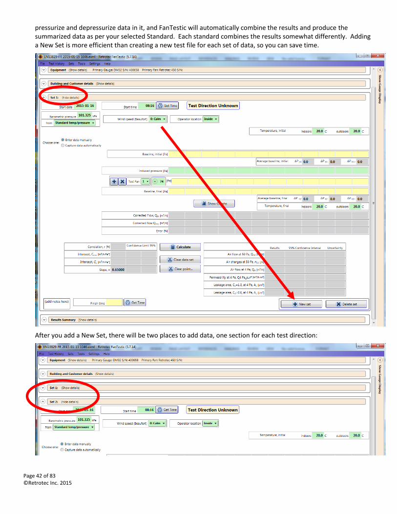
Page 42 of 83 ©Retrotec Inc. 2015
pressurize and depressurize data in it, and FanTestic will automatically combine the results and produce the summarized data as per your selected Standard. Each standard combines the results somewhat differently. Adding a New Set is more efficient than creating a new test file for each set of data, so you can save time.
After you add a New Set, there will be two places to add data, one section for each test direction:
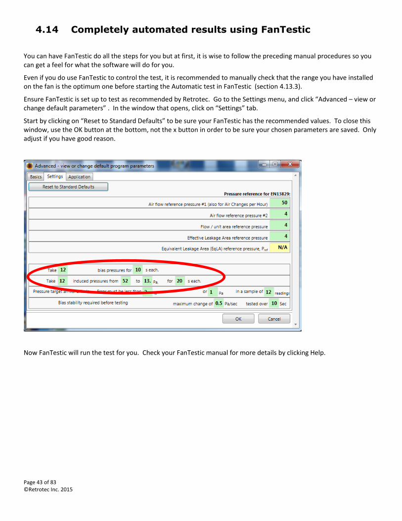
Page 43 of 83 ©Retrotec Inc. 2015
4.14 Completely automated results using FanTestic
You can have FanTestic do all the steps for you but at first, it is wise to follow the preceding manual procedures so you can get a feel for what the software will do for you.
Even if you do use FanTestic to control the test, it is recommended to manually check that the range you have installed on the fan is the optimum one before starting the Automatic test in FanTestic (section 4.13.3).
Ensure FanTestic is set up to test as recommended by Retrotec. Go to the Settings menu, and click “Advanced – view or change default parameters” . In the window that opens, click on “Settings” tab.
Start by clicking on “Reset to Standard Defaults” to be sure your FanTestic has the recommended values. To close this window, use the OK button at the bottom, not the x button in order to be sure your chosen parameters are saved. Only adjust if you have good reason.
Now FanTestic will run the test for you. Check your FanTestic manual for more details by clicking Help.
Page 44 of 83 ©Retrotec Inc. 2015
4.15 Basic Results from Single Point Test
Basic test results from a single-point test can be used to provide a simple and quick assessment of a building's airtightness. The DM-2 digital gauge is capable of displaying most common calculations directly on the screen as the measurements are being made.
4.15.1. Air Leakage at 50 Pascal
The industry standard measurement is CFM50. This is the airflow (in cubic feet per minute) required by the Door Fan to create a pressure difference, between the building interior and the outdoors, of 50 Pascals. This difference is roughly equivalent to the pressure that the building experiences in a 20 mph wind.
4.15.2. Air Changes per hour at 50 Pa - ACH50
ACH50 is the number of complete air changes that will occur in one hour, when a building pressure of 50 Pascals is applied across the building envelope. The value is calculated based on the volume of the enclosure, so it is a useful method of normalizing leakage rate.
4.15.3. Equivalent Leakage Area - EqLA 10
Equivalent leakage area is defined as the area of a hole in a thin panel that would leak the same amount of air as the building does at a pressure of 10 Pa with reference to the outdoors. (Discharge coefficient of 0.61)
4.15.4. Effective Leakage Area - EfLA 4
Effective Leakage Area calculation is defined as the area of the elliptical nozzle-shaped hole that would leak the same amount of air as the building does at a pressure of 4 Pa with reference to the outdoors. (Discharge coefficient of 1.0)
4.16 Results from Multi-Point Procedure
Read Retrotec Manuals on FanTestic Software.
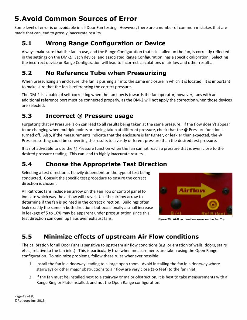
Page 45 of 83 ©Retrotec Inc. 2015
5. Avoid Common Sources of Error
Some level of error is unavoidable in all Door Fan testing. However, there are a number of common mistakes that are made that can lead to grossly inaccurate results.
5.1 Wrong Range Configuration or Device
Always make sure that the fan in use, and the Range Configuration that is installed on the fan, is correctly reflected in the settings on the DM-2. Each device, and associated Range Configuration, has a specific calibration. Selecting the incorrect device or Range Configuration will lead to incorrect calculations of airflow and other results.
5.2 No Reference Tube when Pressurizing
When pressurizing an enclosure, the fan is pushing air into the same enclosure in which it is located. It is important to make sure that the fan is referencing the correct pressure.
The DM-2 is capable of self-correcting when the fan flow is towards the fan operator, however, fans with an additional reference port must be connected properly, as the DM-2 will not apply the correction when those devices are selected.
5.3 Incorrect @ Pressure usage
Forgetting that @ Pressure is on can lead to all results being taken at the same pressure. If the flow doesn't appear to be changing when multiple points are being taken at different pressure, check that the @ Pressure function is turned off. Also, if the measurements indicate that the enclosure is far tighter, or leakier than expected, the @ Pressure setting could be converting the results to a vastly different pressure than the desired test pressure.
It is not advisable to use the @ Pressure function when the fan cannot reach a pressure that is even close to the desired pressure reading. This can lead to highly inaccurate results.
5.4 Choose the Appropriate Test Direction
Selecting a test direction is heavily dependent on the type of test being conducted. Consult the specific test procedure to ensure the correct direction is chosen.
All Retrotec fans include an arrow on the Fan Top or control panel to indicate which way the airflow will travel. Use the airflow arrow to determine if the fan is pointed in the correct direction. Buildings often leak exactly the same in both directions but occasionally a small increase in leakage of 5 to 10% may be apparent under pressurization since this test direction can open up flaps over exhaust fans.
5.5 Minimize effects of upstream Air Flow conditions
The calibration for all Door Fans is sensitive to upstream air flow conditions (e.g. orientation of walls, doors, stairs etc…, relative to the fan inlet). This is particularly true when measurements are taken using the Open Range configuration. To minimize problems, follow these rules whenever possible:
1. Install the fan in a doorway leading to a large open room. Avoid installing the fan in a doorway where stairways or other major obstructions to air flow are very close (1-5 feet) to the fan inlet.
2. If the fan must be installed next to a stairway or major obstruction, it is best to take measurements with a Range Ring or Plate installed, and not the Open Range configuration.
Figure 29: Airflow direction arrow on the Fan Top.
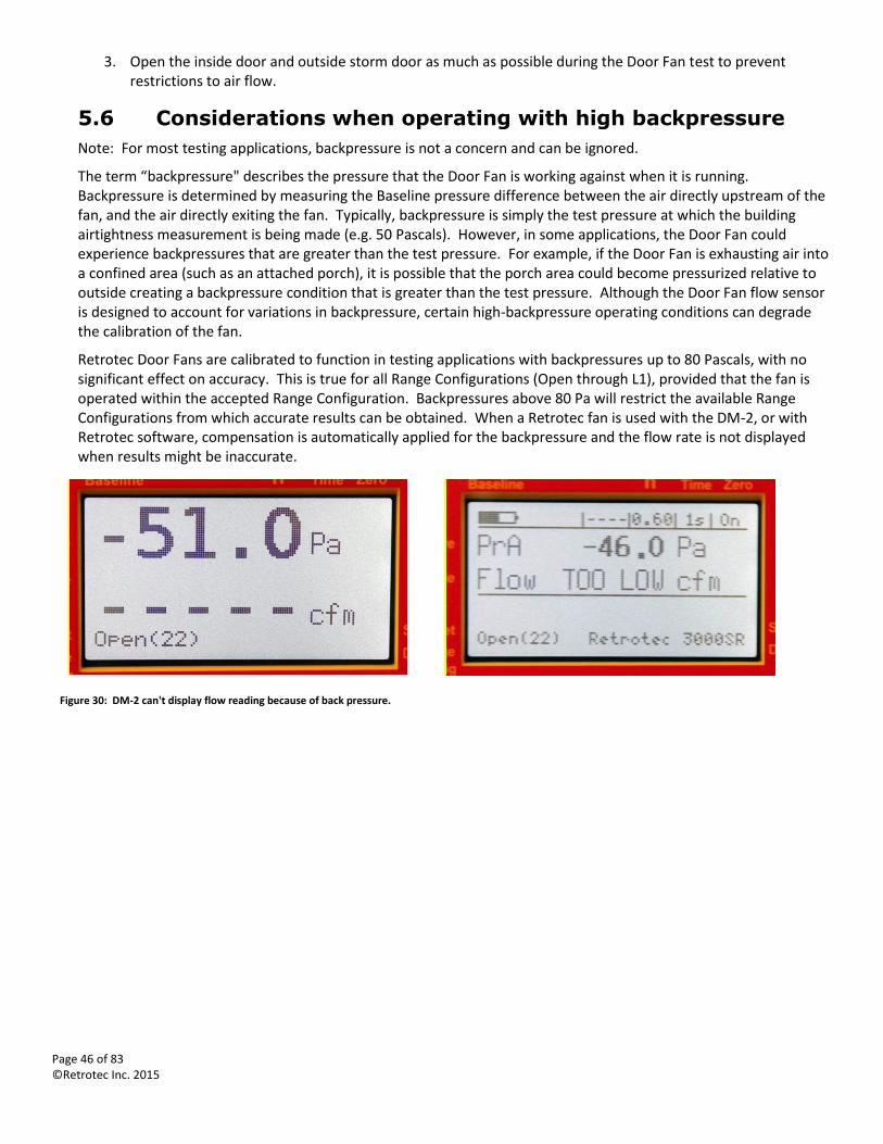
Page 46 of 83 ©Retrotec Inc. 2015
3. Open the inside door and outside storm door as much as possible during the Door Fan test to prevent restrictions to air flow.
5.6 Considerations when operating with high backpressure
Note: For most testing applications, backpressure is not a concern and can be ignored.
The term “backpressure" describes the pressure that the Door Fan is working against when it is running. Backpressure is determined by measuring the Baseline pressure difference between the air directly upstream of the fan, and the air directly exiting the fan. Typically, backpressure is simply the test pressure at which the building airtightness measurement is being made (e.g. 50 Pascals). However, in some applications, the Door Fan could experience backpressures that are greater than the test pressure. For example, if the Door Fan is exhausting air into a confined area (such as an attached porch), it is possible that the porch area could become pressurized relative to outside creating a backpressure condition that is greater than the test pressure. Although the Door Fan flow sensor is designed to account for variations in backpressure, certain high-backpressure operating conditions can degrade the calibration of the fan.
Retrotec Door Fans are calibrated to function in testing applications with backpressures up to 80 Pascals, with no significant effect on accuracy. This is true for all Range Configurations (Open through L1), provided that the fan is operated within the accepted Range Configuration. Backpressures above 80 Pa will restrict the available Range Configurations from which accurate results can be obtained. When a Retrotec fan is used with the DM-2, or with Retrotec software, compensation is automatically applied for the backpressure and the flow rate is not displayed when results might be inaccurate.
Figure 30: DM-2 can't display flow reading because of back pressure.
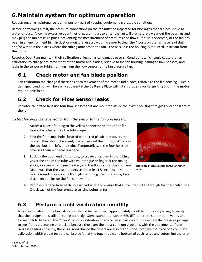
Page 47 of 83 ©Retrotec Inc. 2015
6. Maintain system for optimum operation
Regular ongoing maintenance is an important part of keeping equipment in a usable condition.
Before performing a test, the pressure connections on the fan must be inspected for blockages that can occur due to water or dust. Allowing excessive quantities of gypsum dust to enter the fan will prematurely wear out the bearings and may plug the fan pressure ports, preventing the measurement of pressures and flows. If dust is observed, or the fan has been in an environment high in dust or moisture, use a vacuum cleaner to clear the 4 ports on the fan nacelle of dust and/or water in the places where the tubing attaches to the fan. The nacelle is the housing is mounted upstream from the motor.
Retrotec Door Fans maintain their calibration unless physical damage occurs. Conditions which could cause the fan calibration to change are movement of the motor and blades, relative to the fan housing, damaged flow sensors, and leaks in the sensor or tubing running from the flow sensor to the fan pressure tap.
6.1 Check motor and fan blade position
Fan calibration can change if there has been movement of the motor and blades, relative to the fan housing. Such a damaged condition will be easily apparent if the C8 Range Plate will not sit properly on Range Ring B, or if the motor mount looks bent.
6.2 Check for Flow Sensor leaks
Retrotec calibrated fans use four flow sensors that are mounted inside the plastic housing that goes over the front of the fan.
To test for leaks in the sensor or from the sensor to the fan pressure tap
1. Attach a piece of tubing to the yellow connector on top of the fan. Leave the other end of the tubing open.
2. Find the four small holes located on the red plastic that covers the motor. They should be evenly spaced around the motor, with one on the top, bottom, left, and right. Temporarily seal the four holes by covering them with masking tape.
3. Suck on the open end of the tube, to create a vacuum in the tubing. Cover the end of the tube with your tongue or finger, if the tubing sticks, a vacuum has been created, and the flow sensor does not leak. Make sure that the vacuum persists for at least 5 seconds. If you hear a sound of air moving through the tubing, then there may be a disconnection inside the fan somewhere.
4. Remove the tape from each hole individually, and ensure that air can be sucked through that particular hole. Check each of the four pressure sensing points in turn.
6.3 Perform a field verification monthly
A field verification of the fan calibration should be performed approximately monthly. It is a simple way to verify that the equipment is still operating correctly. Some standards such as RESNET require this to be done yearly and for records to be kept. This “check” is not a calibration of any range in particular but does test the pressure pickups to see if they are leaking or blocked because those are the most common problems with the equipment. If one range is reading correctly, there is a good chance the others are also but this does not take the place of a complete calibration which would test the calibrated fan at the top, middle and bottom of each range and determine the error
Figure 31: Pressure sensor on the fan motor casing.
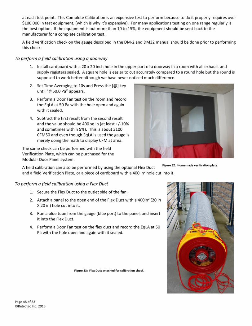
Page 48 of 83 ©Retrotec Inc. 2015
at each test point. This Complete Calibration is an expensive test to perform because to do it properly requires over $100,000 in test equipment, (which is why it’s expensive). For many applications testing on one range regularly is the best option. If the equipment is out more than 10 to 15%, the equipment should be sent back to the manufacturer for a complete calibration test.
A field verification check on the gauge described in the DM-2 and DM32 manual should be done prior to performing this check.
To perform a field calibration using a doorway
1. Install cardboard with a 20 x 20 inch hole in the upper part of a doorway in a room with all exhaust and supply registers sealed. A square hole is easier to cut accurately compared to a round hole but the round is supposed to work better although we have never noticed much difference.
2. Set Time Averaging to 10s and Press the [@] key until “@50.0 Pa” appears.
3. Perform a Door Fan test on the room and record the EqLA at 50 Pa with the hole open and again with it sealed.
4. Subtract the first result from the second result and the value should be 400 sq in (at least +/-10% and sometimes within 5%). This is about 3100 CFM50 and even though EqLA is used the gauge is merely doing the math to display CFM at area.
The same check can be performed with the field Verification Plate, which can be purchased for the Modular Door Panel system.
A field calibration can also be performed by using the optional Flex Duct and a field Verification Plate, or a piece of cardboard with a 400 in2 hole cut into it.
To perform a field calibration using a Flex Duct
1. Secure the Flex Duct to the outlet side of the fan.
2. Attach a panel to the open end of the Flex Duct with a 400in2 (20 in X 20 in) hole cut into it.
3. Run a blue tube from the gauge (blue port) to the panel, and insert it into the Flex Duct.
4. Perform a Door Fan test on the flex duct and record the EqLA at 50 Pa with the hole open and again with it sealed.
Figure 33: Flex Duct attached for calibration check.
Figure 32: Homemade verification plate.
Page 49 of 83 ©Retrotec Inc. 2015
7. Power to run the fan and gauge
7.1 Status lights indicate power and control connections are ready to go
Current Retrotec Door Fans have two LED lights on the Fan Top. “Mains Power” indicates the power status next to the AC power input. The second LED, “Status”, indicates status of the connected gauge.
The 3300(SR) series fan includes a three-phase power supply, which contains two power status lights.
Table 3: 3300SR fans mains power – power input monitoring
3300 Series Fans
100 – 140 VAC, 22 Amp 210 – 260 VAC, 14 Amp Indication
Solid green Off Low voltage input
Solid green Solid green High voltage input
2000 Series Fans Indication
Solid green Voltage input
The 3300(SR) fan will operate at a reduced efficiency level when connected to a low voltage input. It is safe to use, but may not reach its maximum operating speed.
Table 4: DM-2 status light indications
DM-2 Status Light Indicates
Blinking red Lost communication with DM-2
Solid green Good communication with DM-2
Flashing green DM-2 not connected or turned off
7.2 Using the Fan with Mains Power
The 3300 and 3300SR fans are not designed to operate on GFCI protected circuits. Doing so may cause the circuit breaker to trip. Do not operate multiple 3300 or 3300SR fans on the same circuit. Stove top electrical outlets are an ideal 20A circuit to which to connect the 3300(SR) fans.
In European countries where a 50 Hz power system is used the fans will run 20% slower.
7.3 Using the Fan with a power generator
Retrotec recommends a generator with inverter type AC power output. Size the generator capacity above the maximum power required in order to reduce distortion of the AC power waveform. The higher the rated power output, the better. Suggestions for minimum generator output sizes are 3000W for Door Fans and 500W for DucTesters.
Table 5: Acceptable generator power output for specific fans.
Fan Operating
Voltage Max Operating Current (Watts)
Max Inrush Current Minimum Generator
Power Output
3300 - 3 Phase Power supply, double wall fan as found in: QMG, Q4E, Q5E
120VAC 22A (2640W)
Equal due to soft-start ramp-up of inverter. 3000 W
208VAC 13A (2704W)
230VAC 10.5A (2415W)
240VAC 10.3A (2472W)
120VAC 12 (1440W) 15.5A (1860W)
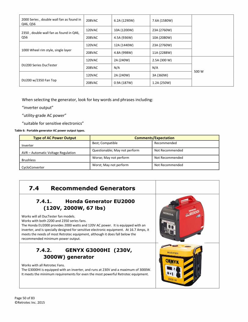
Page 50 of 83 ©Retrotec Inc. 2015
2000 Series , double wall fan as found in Q46, Q56
208VAC 6.2A (1290W) 7.6A (1580W)
2350 , double wall fan as found in Q46, Q56
120VAC 10A (1200W) 23A (2760W)
208VAC 4.5A (936W) 10A (2080W)
1000 Wheel rim style, single layer
120VAC 12A (1440W) 23A (2760W)
208VAC 4.8A (998W) 11A (2288W)
DU200 Series DucTester
120VAC 2A (240W) 2.5A (300 W)
500 W 208VAC N/A N/A
DU200 w/2350 Fan Top
120VAC 2A (240W) 3A (360W)
208VAC 0.9A (187W) 1.2A (250W)
When selecting the generator, look for key words and phrases including:
“inverter output”
“utility-grade AC power”
“suitable for sensitive electronics”
Table 6: Portable generator AC power output types.
Type of AC Power Output Comments/Expectation
Inverter Best; Compatible Recommended
AVR – Automatic Voltage Regulation Questionable; May not perform Not Recommended
Brushless Worse; May not perform Not Recommended
CycloConverter Worst; May not perform Not Recommended
7.4 Recommended Generators
7.4.1. Honda Generator EU2000
(120V, 2000W, 67 lbs)
Works will all DucTester fan models. Works with both 2200 and 2350 series fans. The Honda EU2000 provides 2000 watts and 120V AC power. It is equipped with an inverter, and is specially designed for sensitive electronic equipment. At 16.7 Amps, it meets the needs of most Retrotec equipment, although it does fall below the recommended minimum power output.
7.4.2. GENYX G3000HI (230V,
3000W) generator
Works with all Retrotec Fans. The G3000HI is equipped with an inverter, and runs at 230V and a maximum of 3000W. It meets the minimum requirements for even the most powerful Retrotec equipment.
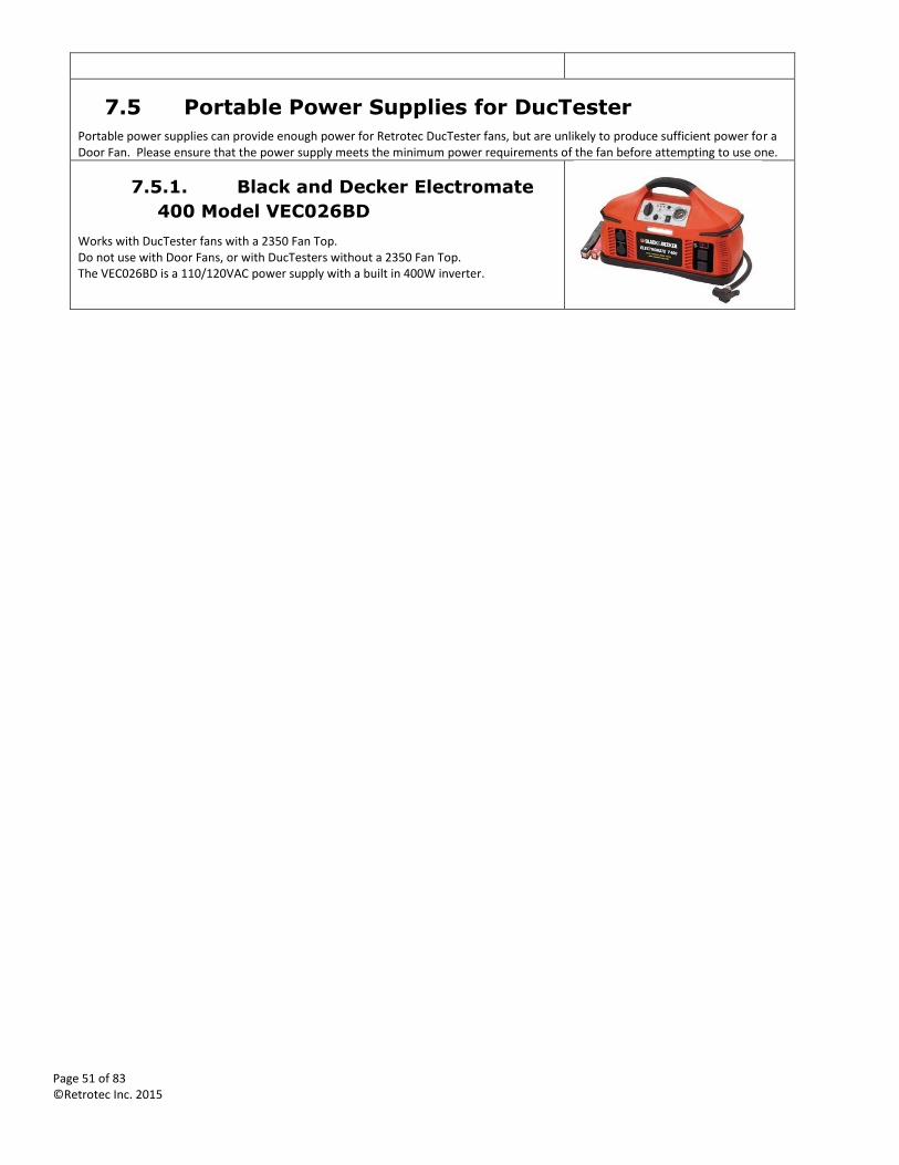
Page 51 of 83 ©Retrotec Inc. 2015
7.5 Portable Power Supplies for DucTester
Portable power supplies can provide enough power for Retrotec DucTester fans, but are unlikely to produce sufficient power for a Door Fan. Please ensure that the power supply meets the minimum power requirements of the fan before attempting to use one.
7.5.1. Black and Decker Electromate
400 Model VEC026BD
Works with DucTester fans with a 2350 Fan Top. Do not use with Door Fans, or with DucTesters without a 2350 Fan Top. The VEC026BD is a 110/120VAC power supply with a built in 400W inverter.
Page 52 of 83 ©Retrotec Inc. 2015
8. Fan Troubleshooting
8.1 Retrotec 2000 series 120 Volt AC motors overheat and shut off
There is a lot of variation from one motor to the next as they come from the manufacturer. Some motors heat up more than others, in spite of undergoing the same manufacturing process. All motors are tested at Retrotec facilities for 1.5 hours under full current and stress. The motors which shut off due to excess heat are rejected, and sent back to the beginning of the production line. Some users, however, may still encounter problems in the field. Below are some points that may be followed to remedy a specific problem.
Make sure the motor runs as close to full speed as possible. The faster it runs, the more air goes through the motor. A rule of thumb is to have the Fan Pressure over 100 Pa and the motor running near full speed. The motor heats up the most at ¾-speed where it draws 13 amps at 120 volts. At full speed the motor will draw less current!
Make sure the C8 Range Plate has the cooling ports in line with the ones on the motor cover. If the mounting indicator sign is in the correct position, this will ensure the ports are fully open.
Ensure that the switch on the speed controller is in the off (0) position at the rocker switch, not just turned down. If left on low speed with the blade not turning, the controller and the motor will be stressed.
The thermal breakers that shut down the motor are not adjustable. To learn when maximum heat is created, put a current meter on the fan, and adjust the fan speed to see when it is pulling maximum current, and therefore creating maximum heat.
More current = more heat.
More airflow through motor = less heat.
A more drastic solution is to change the blade or to cut a quarter inch off the blade tips and re-balance the blade to reduce the load on the motor.
8.2 3300 High Power Fan will not control smoothly
Retrotec 3300 series variable-frequency fans require 100-280 VAC 50/60 Hz power in order to operate reliably. Voltage drops due to line losses and fluctuations in AC power can be significant. The fans will not work at line voltages of less than 95 VAC.
If the system will:
1. Not control smoothly
2. Slow suddenly
3. Stop completely
4. Produce less than 6,500CFM @100% speed
5. Multi-fan systems will oscillate, with fans running at varying speeds
The problem is likely that insufficient line voltage is arriving at the variable-frequency power supply.
To resolve the lack of smooth control issue
1. Use a 240VAC Stove or Dryer outlet or
2. Use 208VAC or
3. Reduce extension cord length on 120V circuits and/or use an industrial quality 12 gauge extension wire.
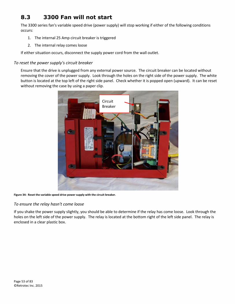
Page 53 of 83 ©Retrotec Inc. 2015
8.3 3300 Fan will not start
The 3300 series fan's variable speed drive (power supply) will stop working if either of the following conditions occurs:
1. The internal 25 Amp circuit breaker is triggered
2. The internal relay comes loose
If either situation occurs, disconnect the supply power cord from the wall outlet.
To reset the power supply's circuit breaker
Ensure that the drive is unplugged from any external power source. The circuit breaker can be located without removing the cover of the power supply. Look through the holes on the right side of the power supply. The white button is located at the top left of the right side panel. Check whether it is popped open (upward). It can be reset without removing the case by using a paper clip.
Figure 34: Reset the variable speed drive power supply with the circuit breaker.
To ensure the relay hasn't come loose
If you shake the power supply slightly, you should be able to determine if the relay has come loose. Look through the holes on the left side of the power supply. The relay is located at the bottom right of the left side panel. The relay is enclosed in a clear plastic box.
Circuit Breaker
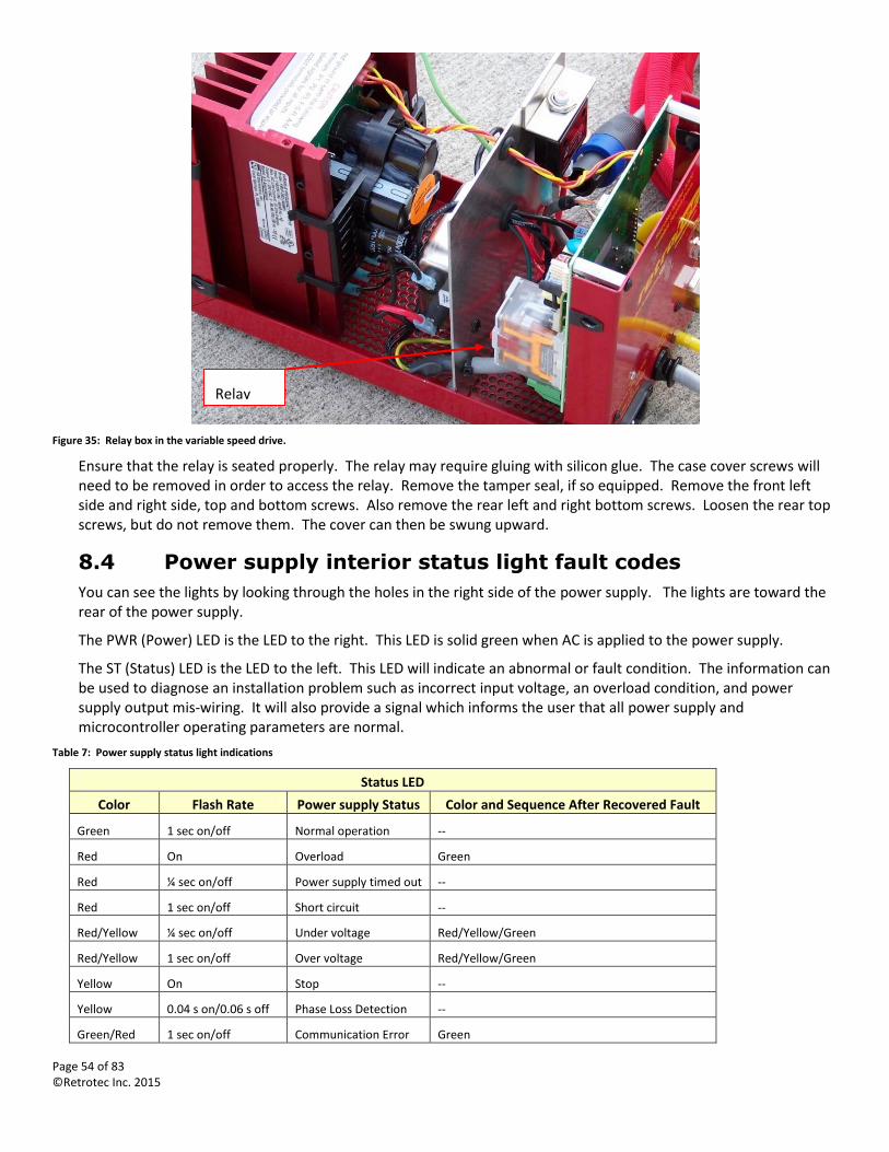
Page 54 of 83 ©Retrotec Inc. 2015
Figure 35: Relay box in the variable speed drive.
Ensure that the relay is seated properly. The relay may require gluing with silicon glue. The case cover screws will need to be removed in order to access the relay. Remove the tamper seal, if so equipped. Remove the front left side and right side, top and bottom screws. Also remove the rear left and right bottom screws. Loosen the rear top screws, but do not remove them. The cover can then be swung upward.
8.4 Power supply interior status light fault codes
You can see the lights by looking through the holes in the right side of the power supply. The lights are toward the rear of the power supply.
The PWR (Power) LED is the LED to the right. This LED is solid green when AC is applied to the power supply.
The ST (Status) LED is the LED to the left. This LED will indicate an abnormal or fault condition. The information can be used to diagnose an installation problem such as incorrect input voltage, an overload condition, and power supply output mis-wiring. It will also provide a signal which informs the user that all power supply and microcontroller operating parameters are normal.
Table 7: Power supply status light indications
Status LED
Color Flash Rate Power supply Status Color and Sequence After Recovered Fault
Green 1 sec on/off Normal operation --
Red On Overload Green
Red ¼ sec on/off Power supply timed out --
Red 1 sec on/off Short circuit --
Red/Yellow ¼ sec on/off Under voltage Red/Yellow/Green
Red/Yellow 1 sec on/off Over voltage Red/Yellow/Green
Yellow On Stop --
Yellow 0.04 s on/0.06 s off Phase Loss Detection --
Green/Red 1 sec on/off Communication Error Green
Relay Box
Page 55 of 83 ©Retrotec Inc. 2015
Appendix A: Calculate Airflow Manually
When testing without a computer, or when testing very large or leaky buildings, it may be necessary to calculate the airflow manually.
Note: Manual calculations are really only appropriate for Single Reading Tests. It is possible to do a Multi-Reading Test manually and attempt to plot out the results on log-log graph paper, but it is not recommended.
To calculate airflow
1. Record the Door Fan Range Configuration.
2. Adjust the fan speed to achieve the desired Room Pressure.
3. Record the Fan Pressure (Channel B on the DM-2, lower two gauges on the analog gauge clip).
If using a computer program:
4. Record the indoor and outdoor temperature.
5. Record the airflow direction.
6. Input the induced Room Pressure and the Fan Pressure into the software, and calculate the results.
If calculating manually:
7. When pressurizing (flow towards operator), subtract the Room Pressure from the Fan Pressure to determine the true Fan Pressure.
8. Using the Manual Flow Tables listed in the DM-2 Operation Manual, locate the true Fan Pressure in the left column and read the airflow under the appropriate Range Configuration column.
Manually calculated flows may vary from the more accurate computer output for several reasons:
The Fan Pressure is corrected for Room Pressure which is not known so is approximated to equal Fan Pressure.
The computer corrects each input for gauge error.
The computer may add a fan correction factor K4.
In spite of these reasons, manually calculated results will typically be within 2% of the computer result.
When using multiple fans, never add Fan Pressures, they aren't additive. Determine airflows in CFM separately and add the flows together to determine total airflow.
The Manual Flow Tables are listed in the DM-2 Operation Manual and DM32 Operation Manual.
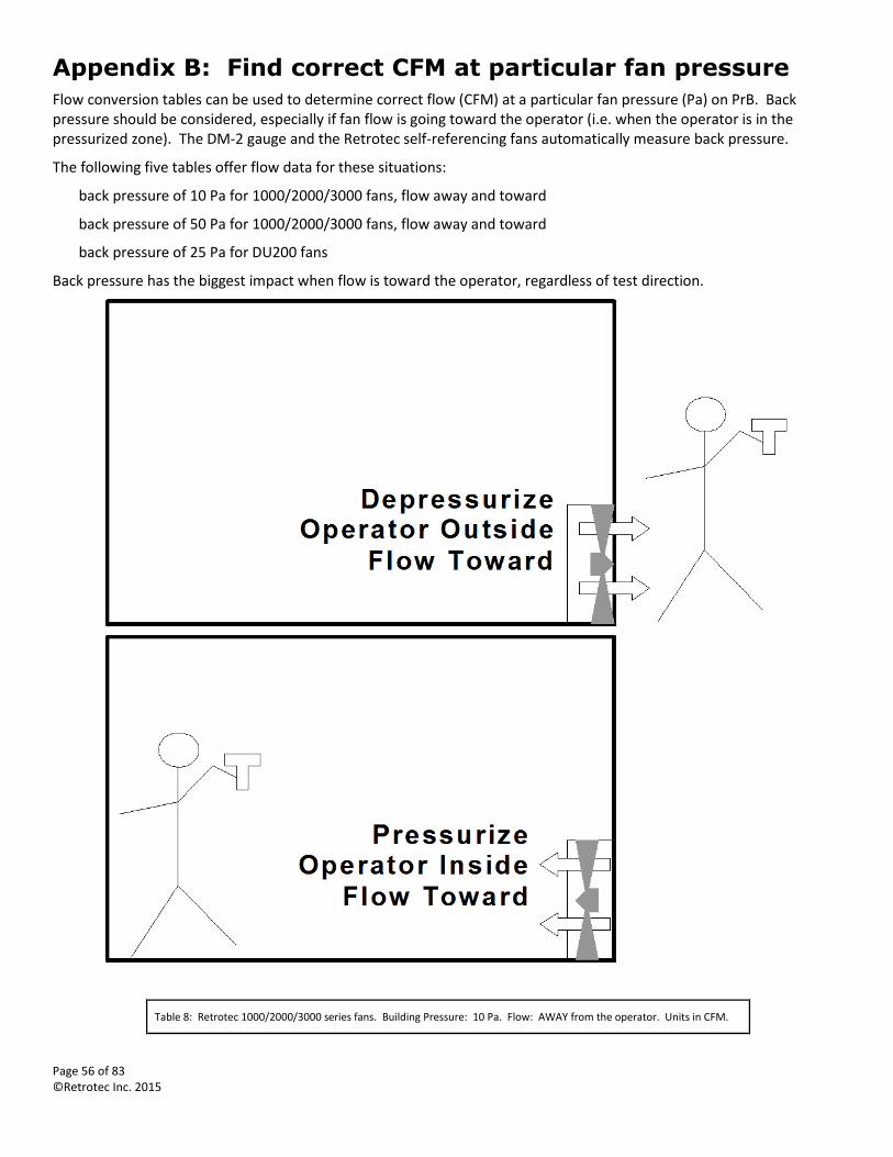
Page 56 of 83 ©Retrotec Inc. 2015
Appendix B: Find correct CFM at particular fan pressure
Flow conversion tables can be used to determine correct flow (CFM) at a particular fan pressure (Pa) on PrB. Back pressure should be considered, especially if fan flow is going toward the operator (i.e. when the operator is in the pressurized zone). The DM-2 gauge and the Retrotec self-referencing fans automatically measure back pressure.
The following five tables offer flow data for these situations:
back pressure of 10 Pa for 1000/2000/3000 fans, flow away and toward
back pressure of 50 Pa for 1000/2000/3000 fans, flow away and toward
back pressure of 25 Pa for DU200 fans
Back pressure has the biggest impact when flow is toward the operator, regardless of test direction.
Table 8: Retrotec 1000/2000/3000 series fans. Building Pressure: 10 Pa. Flow: AWAY from the operator. Units in CFM.
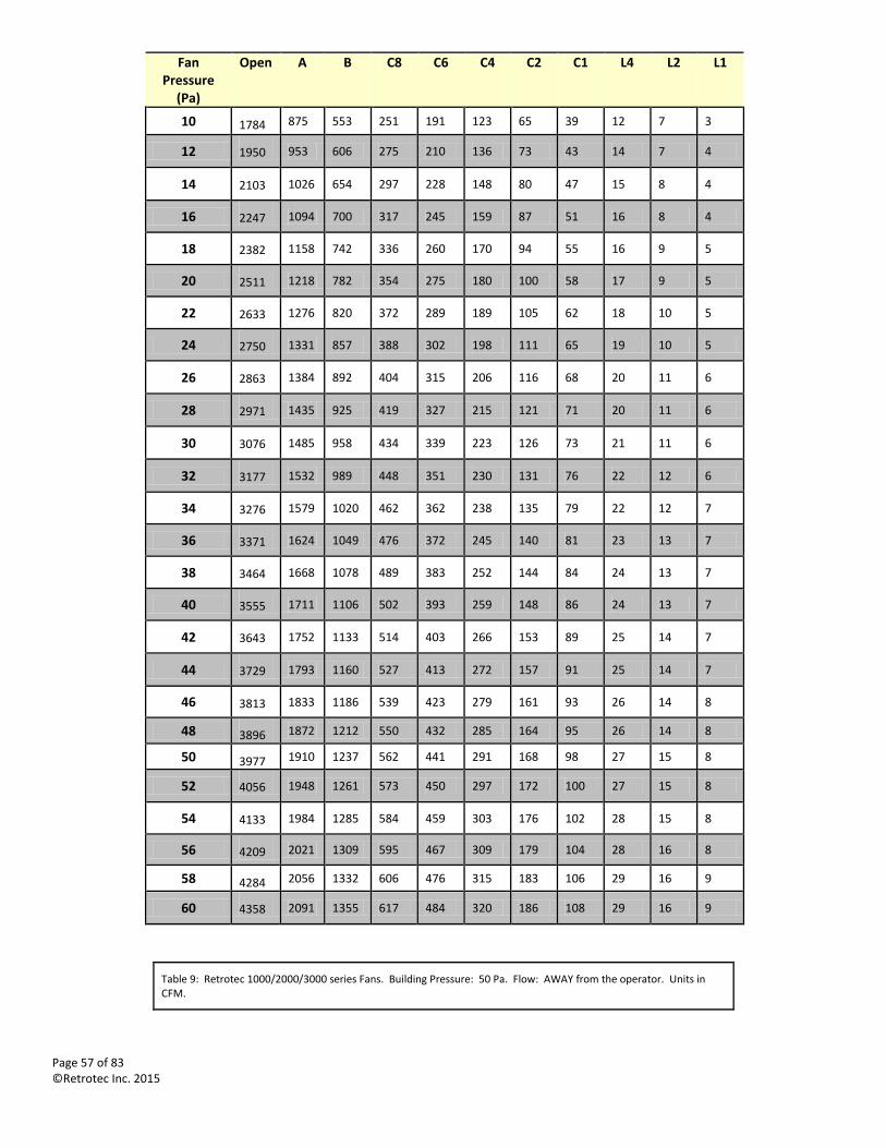
Page 57 of 83 ©Retrotec Inc. 2015
Fan Pressure
(Pa)
Open A B C8 C6 C4 C2 C1 L4 L2 L1
10 1784 875 553 251 191 123 65 39 12 7 3
12 1950 953 606 275 210 136 73 43 14 7 4
14 2103 1026 654 297 228 148 80 47 15 8 4
16 2247 1094 700 317 245 159 87 51 16 8 4
18 2382 1158 742 336 260 170 94 55 16 9 5
20 2511 1218 782 354 275 180 100 58 17 9 5
22 2633 1276 820 372 289 189 105 62 18 10 5
24 2750 1331 857 388 302 198 111 65 19 10 5
26 2863 1384 892 404 315 206 116 68 20 11 6
28 2971 1435 925 419 327 215 121 71 20 11 6
30 3076 1485 958 434 339 223 126 73 21 11 6
32 3177 1532 989 448 351 230 131 76 22 12 6
34 3276 1579 1020 462 362 238 135 79 22 12 7
36 3371 1624 1049 476 372 245 140 81 23 13 7
38 3464 1668 1078 489 383 252 144 84 24 13 7
40 3555 1711 1106 502 393 259 148 86 24 13 7
42 3643 1752 1133 514 403 266 153 89 25 14 7
44 3729 1793 1160 527 413 272 157 91 25 14 7
46 3813 1833 1186 539 423 279 161 93 26 14 8
48 3896 1872 1212 550 432 285 164 95 26 14 8
50 3977 1910 1237 562 441 291 168 98 27 15 8
52 4056 1948 1261 573 450 297 172 100 27 15 8
54 4133 1984 1285 584 459 303 176 102 28 15 8
56 4209 2021 1309 595 467 309 179 104 28 16 8
58 4284 2056 1332 606 476 315 183 106 29 16 9
60 4358 2091 1355 617 484 320 186 108 29 16 9
Table 9: Retrotec 1000/2000/3000 series Fans. Building Pressure: 50 Pa. Flow: AWAY from the operator. Units in CFM.
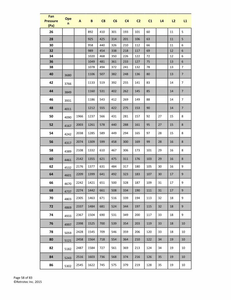
Page 58 of 83 ©Retrotec Inc. 2015
Fan Pressure
(Pa)
Open
A B C8 C6 C4 C2 C1 L4 L2 L1
26 892 410 301 193 101 60 11 5
28 925 425 314 201 106 63 11 5
30
958 440 326 210 112 66 11 6
32
989 454 338 218 117 69 12 6
34
1020 468 350 226 122 72 12 6
36
1049 481 361 233 127 75 13 6
38
1078 494 372 241 132 78 13 7
40 3680 1106 507 382 248 136 80 13 7
42 3766 1133 519 392 255 141 83 14 7
44 3849 1160 531 402 262 145 85 14 7
46 3931 1186 543 412 269 149 88 14 7
48 4011 1212 555 422 275 153 90 14 7
50 4090 1966 1237 566 431 281 157 92 27 15 8
52 4167 2003 1261 578 440 288 161 95 27 15 8
54 4242 2038 1285 589 449 294 165 97 28 15 8
56 4317 2074 1309 599 458 300 169 99 28 16 8
58 4389 2108 1332 610 467 306 173 101 29 16 8
60 4461 2142 1355 621 475 311 176 103 29 16 8
62 4532 2176 1377 631 484 317 180 105 30 16 9
64 4601 2209 1399 641 492 323 183 107 30 17 9
66 4670 2242 1421 651 500 328 187 109 31 17 9
68 4737 2274 1442 661 508 334 190 111 31 17 9
70 4803 2305 1463 671 516 339 194 113 32 18 9
72 4869 2337 1484 681 524 344 197 115 32 18 9
74 4933 2367 1504 690 531 349 200 117 33 18 9
76 4997 2398 1525 700 539 354 203 119 33 18 10
78 5059 2428 1545 709 546 359 206 120 33 18 10
80 5121 2458 1564 718 554 364 210 122 34 19 10
82 5182 2487 1584 727 561 369 213 124 34 19 10
84 5243 2516 1603 736 568 374 216 126 35 19 10
86 5302 2545 1622 745 575 379 219 128 35 19 10
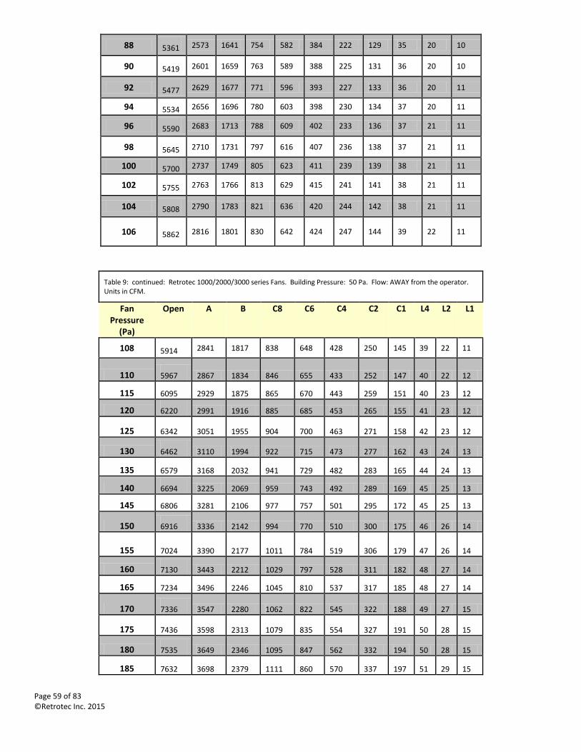
Page 59 of 83 ©Retrotec Inc. 2015
88 5361 2573 1641 754 582 384 222 129 35 20 10
90 5419 2601 1659 763 589 388 225 131 36 20 10
92 5477 2629 1677 771 596 393 227 133 36 20 11
94 5534 2656 1696 780 603 398 230 134 37 20 11
96 5590 2683 1713 788 609 402 233 136 37 21 11
98 5645 2710 1731 797 616 407 236 138 37 21 11
100 5700 2737 1749 805 623 411 239 139 38 21 11
102 5755 2763 1766 813 629 415 241 141 38 21 11
104 5808 2790 1783 821 636 420 244 142 38 21 11
106 5862 2816 1801 830 642 424 247 144 39 22 11
Table 9: continued: Retrotec 1000/2000/3000 series Fans. Building Pressure: 50 Pa. Flow: AWAY from the operator. Units in CFM.
Fan Pressure
(Pa)
Open A B C8 C6 C4 C2 C1 L4 L2 L1
108 5914 2841 1817 838 648 428 250 145 39 22 11
110 5967 2867 1834 846 655 433 252 147 40 22 12
115 6095 2929 1875 865 670 443 259 151 40 23 12
120 6220 2991 1916 885 685 453 265 155 41 23 12
125 6342 3051 1955 904 700 463 271 158 42 23 12
130 6462 3110 1994 922 715 473 277 162 43 24 13
135 6579 3168 2032 941 729 482 283 165 44 24 13
140 6694 3225 2069 959 743 492 289 169 45 25 13
145 6806 3281 2106 977 757 501 295 172 45 25 13
150 6916 3336 2142 994 770 510 300 175 46 26 14
155 7024 3390 2177 1011 784 519 306 179 47 26 14
160 7130 3443 2212 1029 797 528 311 182 48 27 14
165 7234 3496 2246 1045 810 537 317 185 48 27 14
170 7336 3547 2280 1062 822 545 322 188 49 27 15
175 7436 3598 2313 1079 835 554 327 191 50 28 15
180 7535 3649 2346 1095 847 562 332 194 50 28 15
185 7632 3698 2379 1111 860 570 337 197 51 29 15
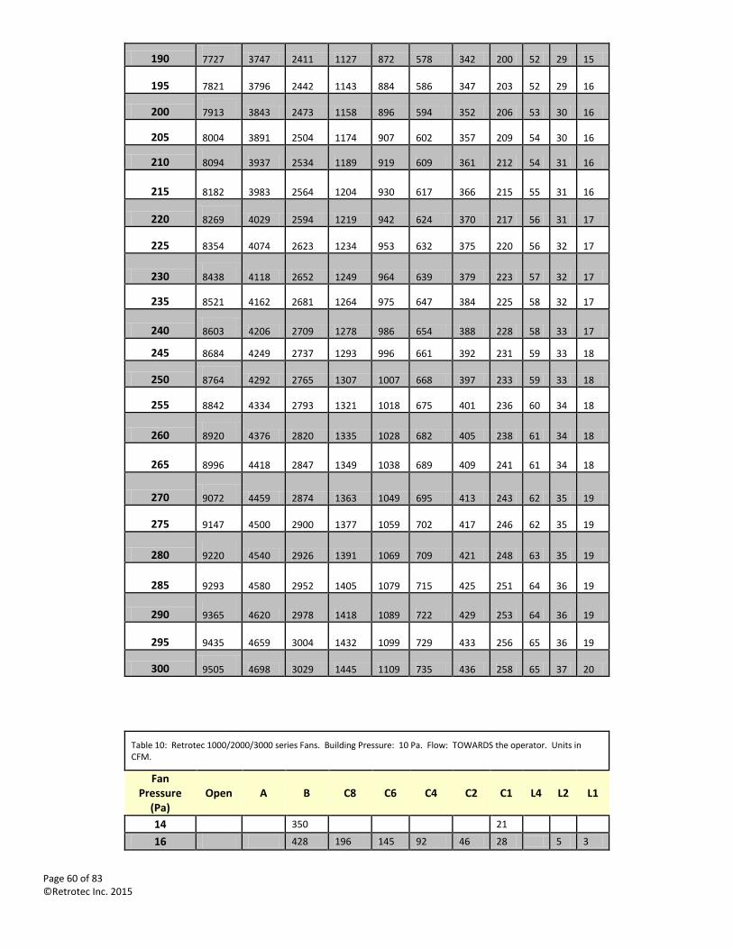
Page 60 of 83 ©Retrotec Inc. 2015
190 7727 3747 2411 1127 872 578 342 200 52 29 15
195 7821 3796 2442 1143 884 586 347 203 52 29 16
200 7913 3843 2473 1158 896 594 352 206 53 30 16
205 8004 3891 2504 1174 907 602 357 209 54 30 16
210 8094 3937 2534 1189 919 609 361 212 54 31 16
215 8182 3983 2564 1204 930 617 366 215 55 31 16
220 8269 4029 2594 1219 942 624 370 217 56 31 17
225 8354 4074 2623 1234 953 632 375 220 56 32 17
230 8438 4118 2652 1249 964 639 379 223 57 32 17
235 8521 4162 2681 1264 975 647 384 225 58 32 17
240 8603 4206 2709 1278 986 654 388 228 58 33 17
245 8684 4249 2737 1293 996 661 392 231 59 33 18
250 8764 4292 2765 1307 1007 668 397 233 59 33 18
255 8842 4334 2793 1321 1018 675 401 236 60 34 18
260 8920 4376 2820 1335 1028 682 405 238 61 34 18
265 8996 4418 2847 1349 1038 689 409 241 61 34 18
270 9072 4459 2874 1363 1049 695 413 243 62 35 19
275 9147 4500 2900 1377 1059 702 417 246 62 35 19
280 9220 4540 2926 1391 1069 709 421 248 63 35 19
285 9293 4580 2952 1405 1079 715 425 251 64 36 19
290 9365 4620 2978 1418 1089 722 429 253 64 36 19
295 9435 4659 3004 1432 1099 729 433 256 65 36 19
300 9505 4698 3029 1445 1109 735 436 258 65 37 20
Table 10: Retrotec 1000/2000/3000 series Fans. Building Pressure: 10 Pa. Flow: TOWARDS the operator. Units in CFM.
Fan Pressure
(Pa) Open A B C8 C6 C4 C2 C1 L4 L2 L1
14 350 21
16 428 196 145 92 46 28 5 3
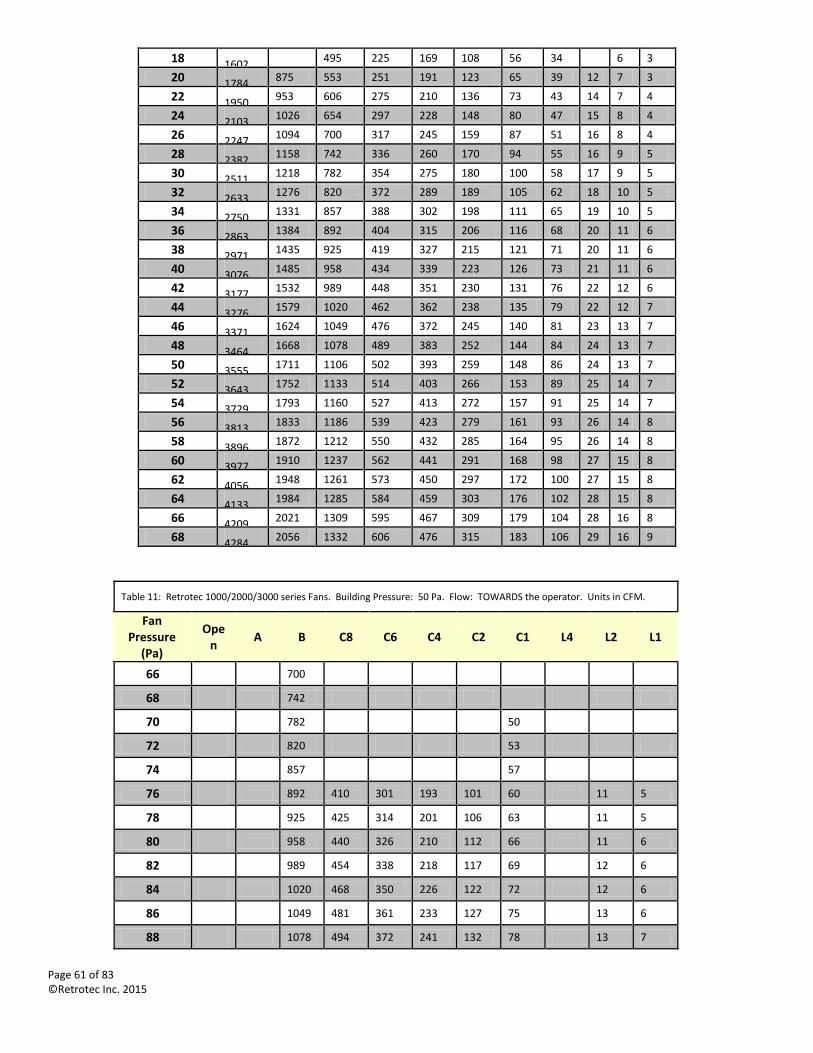
Page 61 of 83 ©Retrotec Inc. 2015
18 1602 495 225 169 108 56 34 6 3
20 1784 875 553 251 191 123 65 39 12 7 3
22 1950 953 606 275 210 136 73 43 14 7 4
24 2103 1026 654 297 228 148 80 47 15 8 4
26 2247 1094 700 317 245 159 87 51 16 8 4
28 2382 1158 742 336 260 170 94 55 16 9 5
30 2511 1218 782 354 275 180 100 58 17 9 5
32 2633 1276 820 372 289 189 105 62 18 10 5
34 2750 1331 857 388 302 198 111 65 19 10 5
36 2863 1384 892 404 315 206 116 68 20 11 6
38 2971 1435 925 419 327 215 121 71 20 11 6
40 3076 1485 958 434 339 223 126 73 21 11 6
42 3177 1532 989 448 351 230 131 76 22 12 6
44 3276 1579 1020 462 362 238 135 79 22 12 7
46 3371 1624 1049 476 372 245 140 81 23 13 7
48 3464 1668 1078 489 383 252 144 84 24 13 7
50 3555 1711 1106 502 393 259 148 86 24 13 7
52 3643 1752 1133 514 403 266 153 89 25 14 7
54 3729 1793 1160 527 413 272 157 91 25 14 7
56 3813 1833 1186 539 423 279 161 93 26 14 8
58 3896 1872 1212 550 432 285 164 95 26 14 8
60 3977 1910 1237 562 441 291 168 98 27 15 8
62 4056 1948 1261 573 450 297 172 100 27 15 8
64 4133 1984 1285 584 459 303 176 102 28 15 8
66 4209 2021 1309 595 467 309 179 104 28 16 8
68 4284 2056 1332 606 476 315 183 106 29 16 9
Table 11: Retrotec 1000/2000/3000 series Fans. Building Pressure: 50 Pa. Flow: TOWARDS the operator. Units in CFM.
Fan Pressure
(Pa)
Open
A B C8 C6 C4 C2 C1 L4 L2 L1
66 700
68 742
70 782 50
72 820 53
74 857 57
76 892 410 301 193 101 60 11 5
78 925 425 314 201 106 63 11 5
80 958 440 326 210 112 66 11 6
82 989 454 338 218 117 69 12 6
84 1020 468 350 226 122 72 12 6
86 1049 481 361 233 127 75 13 6
88 1078 494 372 241 132 78 13 7
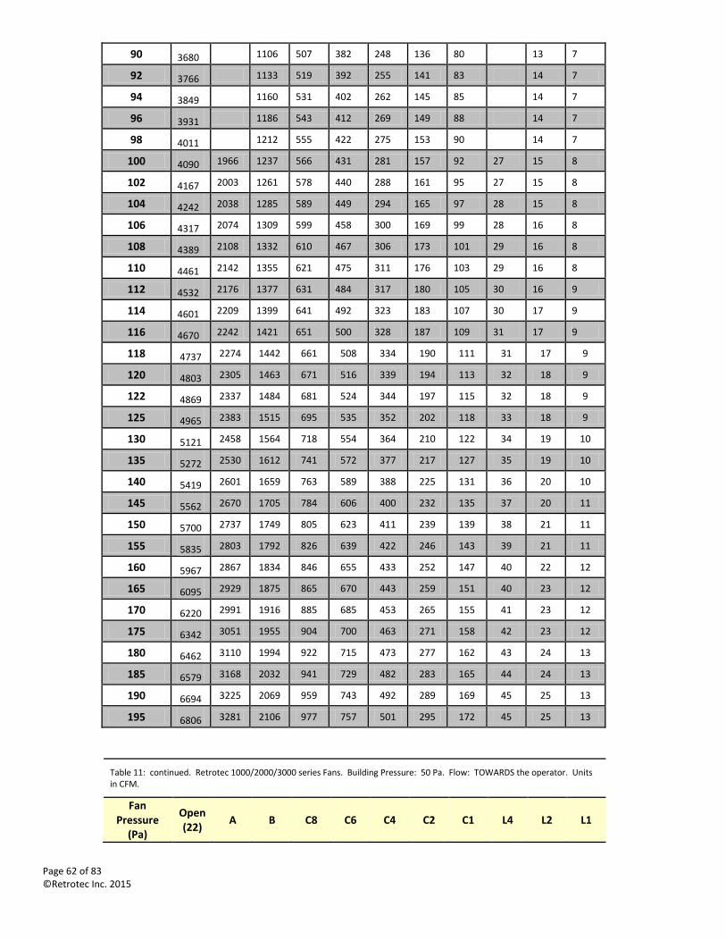
Page 62 of 83 ©Retrotec Inc. 2015
90 3680 1106 507 382 248 136 80 13 7
92 3766 1133 519 392 255 141 83 14 7
94 3849 1160 531 402 262 145 85 14 7
96 3931 1186 543 412 269 149 88 14 7
98 4011 1212 555 422 275 153 90 14 7
100 4090 1966 1237 566 431 281 157 92 27 15 8
102 4167 2003 1261 578 440 288 161 95 27 15 8
104 4242 2038 1285 589 449 294 165 97 28 15 8
106 4317 2074 1309 599 458 300 169 99 28 16 8
108 4389 2108 1332 610 467 306 173 101 29 16 8
110 4461 2142 1355 621 475 311 176 103 29 16 8
112 4532 2176 1377 631 484 317 180 105 30 16 9
114 4601 2209 1399 641 492 323 183 107 30 17 9
116 4670 2242 1421 651 500 328 187 109 31 17 9
118 4737 2274 1442 661 508 334 190 111 31 17 9
120 4803 2305 1463 671 516 339 194 113 32 18 9
122 4869 2337 1484 681 524 344 197 115 32 18 9
125 4965 2383 1515 695 535 352 202 118 33 18 9
130 5121 2458 1564 718 554 364 210 122 34 19 10
135 5272 2530 1612 741 572 377 217 127 35 19 10
140 5419 2601 1659 763 589 388 225 131 36 20 10
145 5562 2670 1705 784 606 400 232 135 37 20 11
150 5700 2737 1749 805 623 411 239 139 38 21 11
155 5835 2803 1792 826 639 422 246 143 39 21 11
160 5967 2867 1834 846 655 433 252 147 40 22 12
165 6095 2929 1875 865 670 443 259 151 40 23 12
170 6220 2991 1916 885 685 453 265 155 41 23 12
175 6342 3051 1955 904 700 463 271 158 42 23 12
180 6462 3110 1994 922 715 473 277 162 43 24 13
185 6579 3168 2032 941 729 482 283 165 44 24 13
190 6694 3225 2069 959 743 492 289 169 45 25 13
195 6806 3281 2106 977 757 501 295 172 45 25 13
Table 11: continued. Retrotec 1000/2000/3000 series Fans. Building Pressure: 50 Pa. Flow: TOWARDS the operator. Units in CFM.
Fan Pressure
(Pa)
Open(22)
A B C8 C6 C4 C2 C1 L4 L2 L1
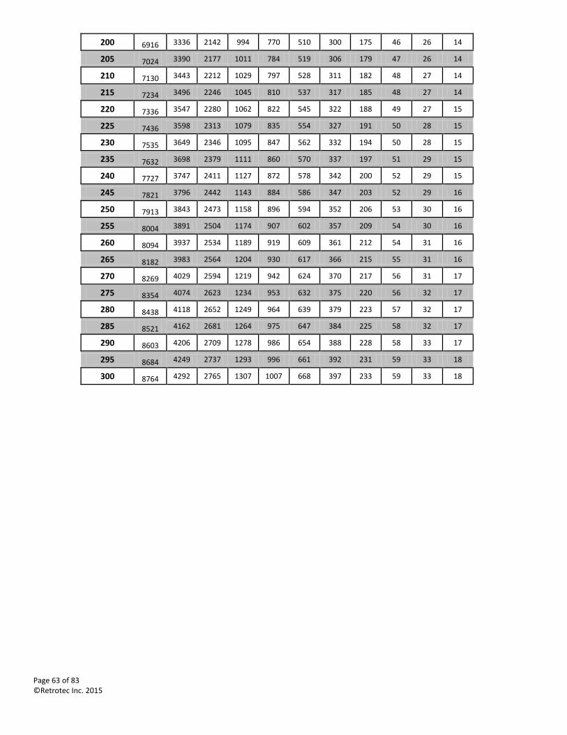
Page 63 of 83 ©Retrotec Inc. 2015
200 6916 3336 2142 994 770 510 300 175 46 26 14
205 7024 3390 2177 1011 784 519 306 179 47 26 14
210 7130 3443 2212 1029 797 528 311 182 48 27 14
215 7234 3496 2246 1045 810 537 317 185 48 27 14
220 7336 3547 2280 1062 822 545 322 188 49 27 15
225 7436 3598 2313 1079 835 554 327 191 50 28 15
230 7535 3649 2346 1095 847 562 332 194 50 28 15
235 7632 3698 2379 1111 860 570 337 197 51 29 15
240 7727 3747 2411 1127 872 578 342 200 52 29 15
245 7821 3796 2442 1143 884 586 347 203 52 29 16
250 7913 3843 2473 1158 896 594 352 206 53 30 16
255 8004 3891 2504 1174 907 602 357 209 54 30 16
260 8094 3937 2534 1189 919 609 361 212 54 31 16
265 8182 3983 2564 1204 930 617 366 215 55 31 16
270 8269 4029 2594 1219 942 624 370 217 56 31 17
275 8354 4074 2623 1234 953 632 375 220 56 32 17
280 8438 4118 2652 1249 964 639 379 223 57 32 17
285 8521 4162 2681 1264 975 647 384 225 58 32 17
290 8603 4206 2709 1278 986 654 388 228 58 33 17
295 8684 4249 2737 1293 996 661 392 231 59 33 18
300 8764 4292 2765 1307 1007 668 397 233 59 33 18
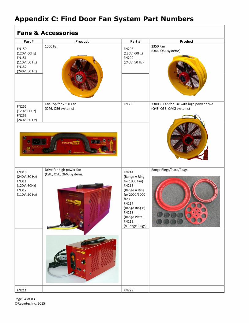
Page 64 of 83 ©Retrotec Inc. 2015
Appendix C: Find Door Fan System Part Numbers
Fans & Accessories
Part # Product Part # Product
FN150 (120V, 60Hz) FN151 (110V, 50 Hz) FN152 (240V, 50 Hz)
1000 Fan
FN208 (120V, 60Hz) FN209 (240V, 50 Hz)
2350 Fan (Q46, Q56 systems)
FN252 (120V, 60Hz) FN256 (240V, 50 Hz)
Fan Top for 2350 Fan (Q46, Q56 systems)
FN309 3300SR Fan for use with high power drive (Q4E, Q5E, QMG systems)
FN310 (240V, 50 Hz) FN311 (120V, 60Hz) FN312 (110V, 50 Hz)
Drive for high power fan (Q4E, Q5E, QMG systems)
FN214 (Range A Ring for 1000 fan) FN216 (Range A Ring for 2000/3000 fan) FN217 (Range Ring B) FN218 (Range Plate) FN219 (8 Range Plugs)
Range Rings/Plate/Plugs
FN211 FN229

Page 65 of 83 ©Retrotec Inc. 2015
Hard Sided Fan Case (2000, 3000 systems)
Cover for Front or Back of Fan (for 2000/3000 series fans)
Aluminum Frame Aluminum Frame dimensions.
Dimensions With Extender Kit
Panel width 24.5 - 41.5 in (62.2 - 105.4 cm) 30 - 48 in (76 - 122 cm)
Panel height 51.5 - 95 in (131 - 241 cm) 60 - 110 in (152 - 280 cm)
Frame thickness 1.75 in (5.3 cm)
Frame case 53 x 10 x 4 in (134 x 25 x 10 cm)
Frame weight 14.2 lbs (6.4 kg)
AL110 Aluminum Frame with Slots, Red Anodized AL215 Extender Kits for height & width, Red
AL112 Crossbar #6, upper, Red AL106 Aluminum Frame Cam Lever Replacement Kit
Page 66 of 83 ©Retrotec Inc. 2015
AL107 Aluminum Frame Replacement Knob
AL113 Alum Frame Replacement Channel Guide Kit (5 Units)
AL114 Alum Frame Replacement Corner Block Kit (Single)
AL115 Alum Frame Replacement Expander Block Kit (Single)
AL103 Case for Standard Aluminum Frame, Gun Style PT111 Aluminum Frame Weather Strip Kit
Picture of weather strip kit
Cloth Door Panels
AL203 Cloth for 1000/2000/3000 Fan, Regular Height
AL211 Cloth for 1000/2000/3000 Fan, Extra Tall & Wide (for use with Extender Kit)
Page 67 of 83 ©Retrotec Inc. 2015
AL206 Cloth for 3000 fan, High Pressure
AL204 Cloth for 2 x 1000/2000/3000 Fans
AL214 Cloth for Low-Flow Fan
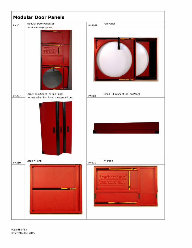
Page 68 of 83 ©Retrotec Inc. 2015
Modular Door Panels
PN201 Modular Door Panel Set (includes carrying case)
PN206R Fan Panel
PN207 Large Fill-in Sheet For Fan Panel (for use when Fan Panel is extended out)
PN208 Small Fill-in Sheet for Fan Panel
PN210 Large-X Panel
PN211 XY Panel
Page 69 of 83 ©Retrotec Inc. 2015
PN209 Small-X Panel PN213 Field Verification Plate for Modular Door Panel
PT112 Weather Strip Repair Kit for Modular Panel (1 panel)
PT110 Weather Strip Repair Kit for Modular Door Panel (4 panels)
Picture of the weather strip Picture of the weather strip
PN212 2000/3000 Fan Panel Blanking Plate
PN204 Panel Case with Shoulder Strap
PN302 3-Fan Molded Panel Set for 2000/3000 fans
(includes 3-Fan Cordura Panel Case)
PN311 3-Fan Molded Panel Cordura Panel Case
FN234 Fan Safety Strap for Modular Door Panels (for securing Door Fan onto Door Panel)
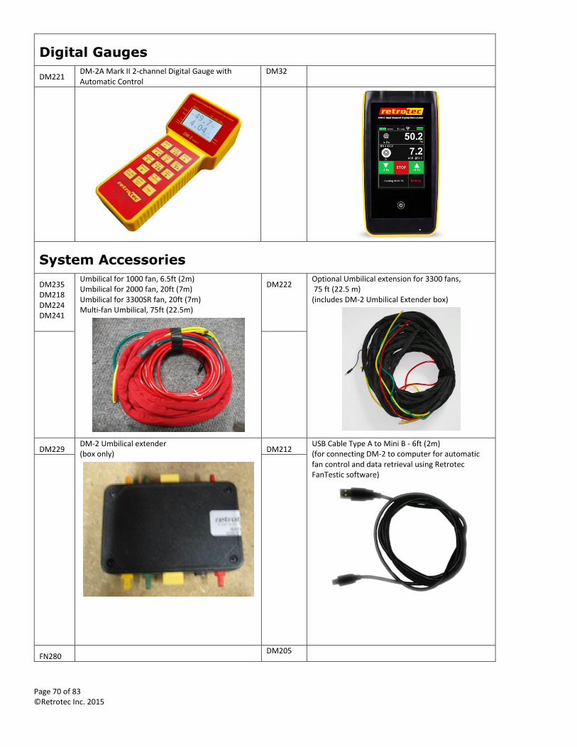
Page 70 of 83 ©Retrotec Inc. 2015
Digital Gauges
DM221 DM-2A Mark II 2-channel Digital Gauge with Automatic Control
DM32
System Accessories
DM235 DM218 DM224 DM241
Umbilical for 1000 fan, 6.5ft (2m) Umbilical for 2000 fan, 20ft (7m) Umbilical for 3300SR fan, 20ft (7m) Multi-fan Umbilical, 75ft (22.5m)
DM222 Optional Umbilical extension for 3300 fans, 75 ft (22.5 m) (includes DM-2 Umbilical Extender box)
DM229 DM-2 Umbilical extender (box only)
DM212 USB Cable Type A to Mini B - 6ft (2m) (for connecting DM-2 to computer for automatic fan control and data retrieval using Retrotec FanTestic software)
FN280 DM205
Page 71 of 83 ©Retrotec Inc. 2015
7 Fan Control Cable Splitter (requires Control Cable: DM205)
Control Cable for 1000/2000/3000 Digital Fan - 20ft (7m)
DM203 (120v or 240v)
9V Country Specific Power Supply DM-2
TU119 Tubing Accessory Kit
(Includes green, yellow, red, and blue tubes (37 ft); Static pressure probe, copper tube, T-connector, male-to-male connector)
CU230 Manual Speed Control (requires Control Cable: DM205)
FX201 Imperial FX202 Metric
1000/2000/3000 Flex Duct (24")
TU101 Basic Wind Damping Kit TU103 Wild Wind Tamer Wind Damping Kit
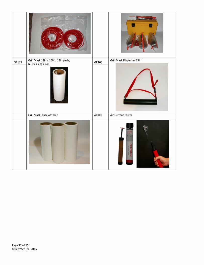
Page 72 of 83 ©Retrotec Inc. 2015
GR113 Grill Mask 12in x 160ft, 12in perfs, hi-stick single roll
GR106 Grill Mask Dispenser 13in
Grill Mask, Case of three AC107 Air Current Tester
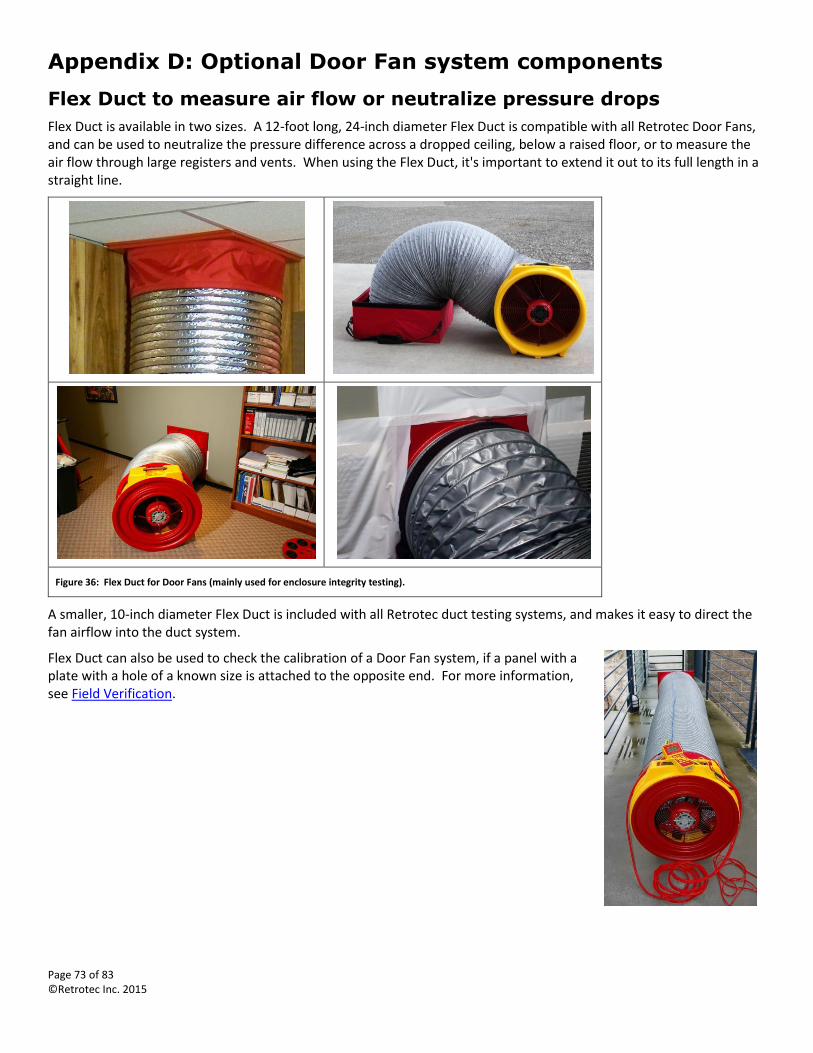
Page 73 of 83 ©Retrotec Inc. 2015
Appendix D: Optional Door Fan system components
Flex Duct to measure air flow or neutralize pressure drops
Flex Duct is available in two sizes. A 12-foot long, 24-inch diameter Flex Duct is compatible with all Retrotec Door Fans, and can be used to neutralize the pressure difference across a dropped ceiling, below a raised floor, or to measure the air flow through large registers and vents. When using the Flex Duct, it's important to extend it out to its full length in a straight line.
Figure 36: Flex Duct for Door Fans (mainly used for enclosure integrity testing).
A smaller, 10-inch diameter Flex Duct is included with all Retrotec duct testing systems, and makes it easy to direct the fan airflow into the duct system.
Flex Duct can also be used to check the calibration of a Door Fan system, if a panel with a plate with a hole of a known size is attached to the opposite end. For more information, see Field Verification.
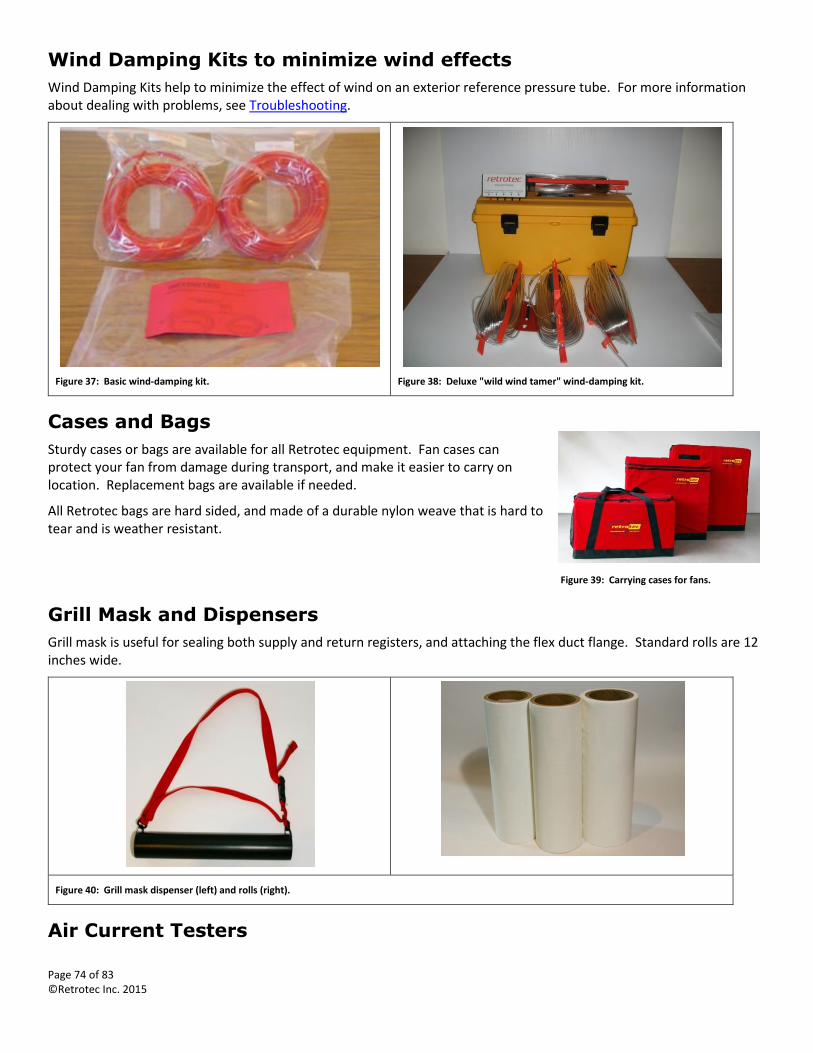
Page 74 of 83 ©Retrotec Inc. 2015
Wind Damping Kits to minimize wind effects
Wind Damping Kits help to minimize the effect of wind on an exterior reference pressure tube. For more information about dealing with problems, see Troubleshooting.
Figure 37: Basic wind-damping kit.
Figure 38: Deluxe "wild wind tamer" wind-damping kit.
Cases and Bags
Sturdy cases or bags are available for all Retrotec equipment. Fan cases can protect your fan from damage during transport, and make it easier to carry on location. Replacement bags are available if needed.
All Retrotec bags are hard sided, and made of a durable nylon weave that is hard to tear and is weather resistant.
Grill Mask and Dispensers
Grill mask is useful for sealing both supply and return registers, and attaching the flex duct flange. Standard rolls are 12 inches wide.
Figure 40: Grill mask dispenser (left) and rolls (right).
Air Current Testers
Figure 39: Carrying cases for fans.
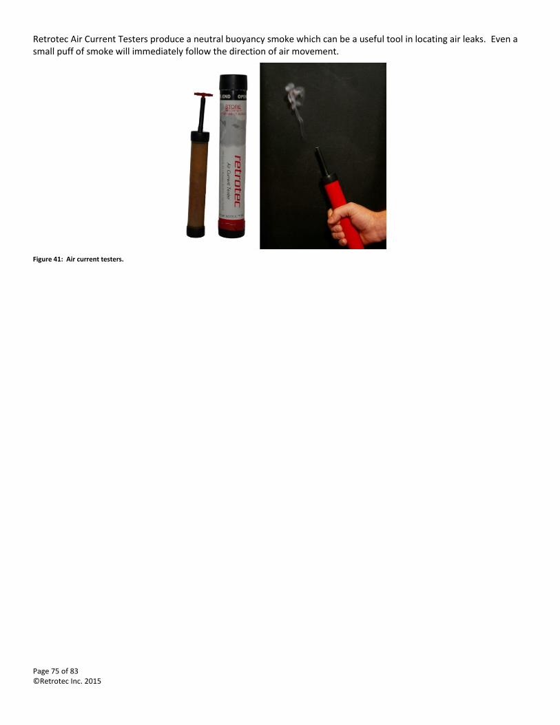
Page 75 of 83 ©Retrotec Inc. 2015
Retrotec Air Current Testers produce a neutral buoyancy smoke which can be a useful tool in locating air leaks. Even a small puff of smoke will immediately follow the direction of air movement.
Figure 41: Air current testers.
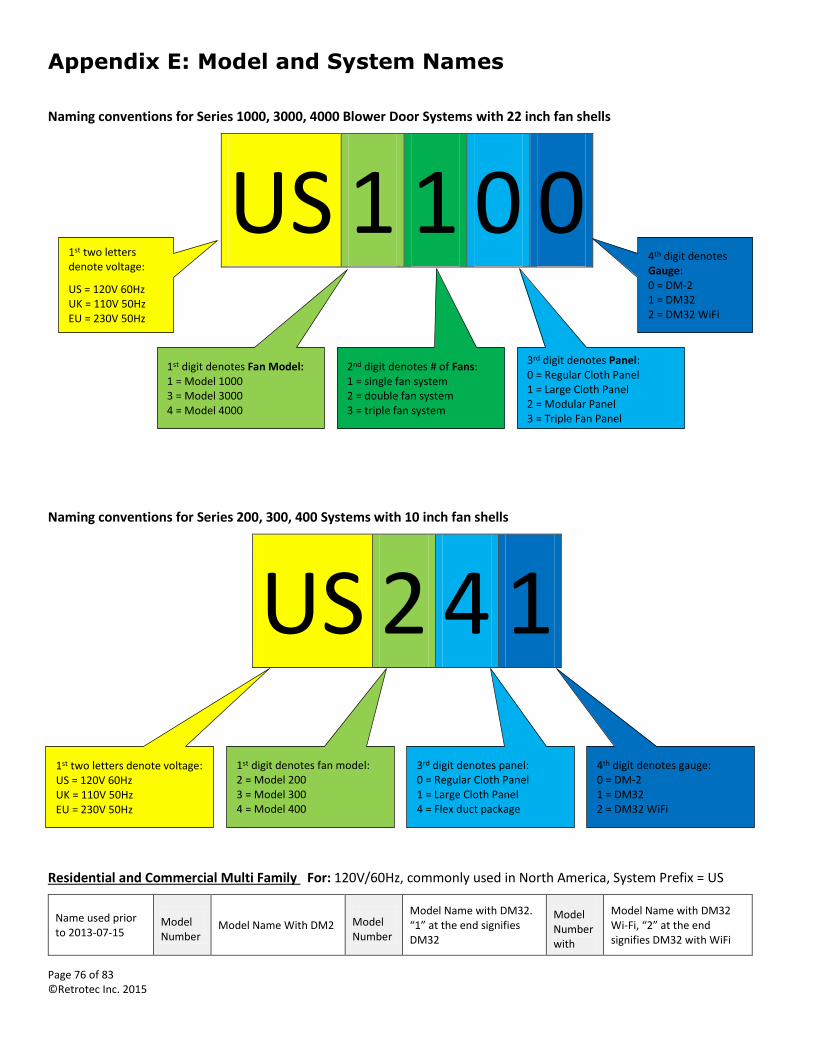
Page 76 of 83 ©Retrotec Inc. 2015
Appendix E: Model and System Names
Naming conventions for Series 1000, 3000, 4000 Blower Door Systems with 22 inch fan shells
US 1 1 0 0
Naming conventions for Series 200, 300, 400 Systems with 10 inch fan shells
US 2 4 1
Residential and Commercial Multi Family For: 120V/60Hz, commonly used in North America, System Prefix = US
Name used prior to 2013-07-15
Model Number
Model Name With DM2 Model Number
Model Name with DM32. “1” at the end signifies DM32
Model Number with
Model Name with DM32 Wi-Fi, “2” at the end signifies DM32 with WiFi
1st two letters denote voltage:
US = 120V 60Hz UK = 110V 50Hz EU = 230V 50Hz
1st digit denotes Fan Model: 1 = Model 1000 3 = Model 3000 4 = Model 4000
2nd digit denotes # of Fans: 1 = single fan system 2 = double fan system 3 = triple fan system
3rd digit denotes Panel: 0 = Regular Cloth Panel 1 = Large Cloth Panel 2 = Modular Panel 3 = Triple Fan Panel
4th digit denotes Gauge: 0 = DM-2 1 = DM32 2 = DM32 WiFi
1st digit denotes fan model: 2 = Model 200 3 = Model 300 4 = Model 400
3rd digit denotes panel: 0 = Regular Cloth Panel 1 = Large Cloth Panel 4 = Flex duct package
4th digit denotes gauge: 0 = DM-2 1 = DM32 2 = DM32 WiFi
1st two letters denote voltage: US = 120V 60Hz UK = 110V 50Hz EU = 230V 50Hz
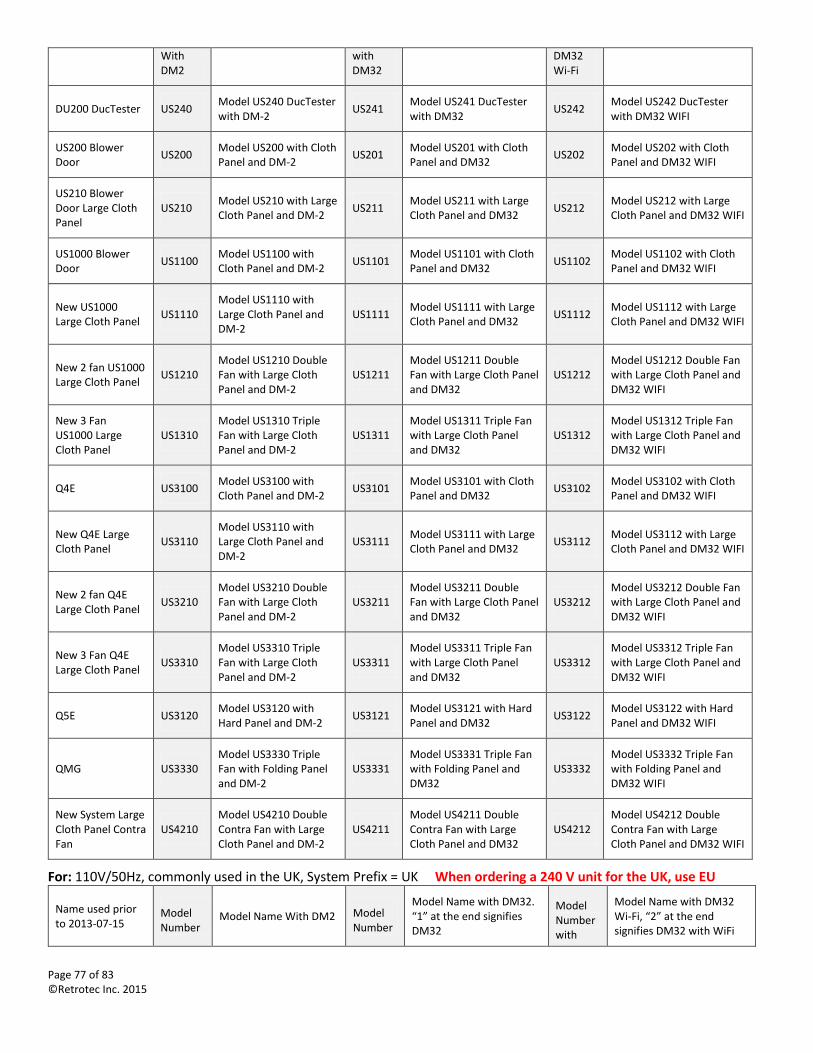
Page 77 of 83 ©Retrotec Inc. 2015
With DM2
with DM32
DM32 Wi-Fi
DU200 DucTester US240 Model US240 DucTester with DM-2
US241 Model US241 DucTester with DM32
US242 Model US242 DucTester with DM32 WIFI
US200 Blower Door
US200 Model US200 with Cloth Panel and DM-2
US201 Model US201 with Cloth Panel and DM32
US202 Model US202 with Cloth Panel and DM32 WIFI
US210 Blower Door Large Cloth Panel
US210 Model US210 with Large Cloth Panel and DM-2
US211 Model US211 with Large Cloth Panel and DM32
US212 Model US212 with Large Cloth Panel and DM32 WIFI
US1000 Blower Door
US1100 Model US1100 with Cloth Panel and DM-2
US1101 Model US1101 with Cloth Panel and DM32
US1102 Model US1102 with Cloth Panel and DM32 WIFI
New US1000 Large Cloth Panel
US1110 Model US1110 with Large Cloth Panel and DM-2
US1111 Model US1111 with Large Cloth Panel and DM32
US1112 Model US1112 with Large Cloth Panel and DM32 WIFI
New 2 fan US1000 Large Cloth Panel
US1210 Model US1210 Double Fan with Large Cloth Panel and DM-2
US1211 Model US1211 Double Fan with Large Cloth Panel and DM32
US1212 Model US1212 Double Fan with Large Cloth Panel and DM32 WIFI
New 3 Fan US1000 Large Cloth Panel
US1310 Model US1310 Triple Fan with Large Cloth Panel and DM-2
US1311 Model US1311 Triple Fan with Large Cloth Panel and DM32
US1312 Model US1312 Triple Fan with Large Cloth Panel and DM32 WIFI
Q4E US3100 Model US3100 with Cloth Panel and DM-2
US3101 Model US3101 with Cloth Panel and DM32
US3102 Model US3102 with Cloth Panel and DM32 WIFI
New Q4E Large Cloth Panel
US3110 Model US3110 with Large Cloth Panel and DM-2
US3111 Model US3111 with Large Cloth Panel and DM32
US3112 Model US3112 with Large Cloth Panel and DM32 WIFI
New 2 fan Q4E Large Cloth Panel
US3210 Model US3210 Double Fan with Large Cloth Panel and DM-2
US3211 Model US3211 Double Fan with Large Cloth Panel and DM32
US3212 Model US3212 Double Fan with Large Cloth Panel and DM32 WIFI
New 3 Fan Q4E Large Cloth Panel
US3310 Model US3310 Triple Fan with Large Cloth Panel and DM-2
US3311 Model US3311 Triple Fan with Large Cloth Panel and DM32
US3312 Model US3312 Triple Fan with Large Cloth Panel and DM32 WIFI
Q5E US3120 Model US3120 with Hard Panel and DM-2
US3121 Model US3121 with Hard Panel and DM32
US3122 Model US3122 with Hard Panel and DM32 WIFI
QMG US3330 Model US3330 Triple Fan with Folding Panel and DM-2
US3331 Model US3331 Triple Fan with Folding Panel and DM32
US3332 Model US3332 Triple Fan with Folding Panel and DM32 WIFI
New System Large Cloth Panel Contra Fan
US4210 Model US4210 Double Contra Fan with Large Cloth Panel and DM-2
US4211 Model US4211 Double Contra Fan with Large Cloth Panel and DM32
US4212 Model US4212 Double Contra Fan with Large Cloth Panel and DM32 WIFI
For: 110V/50Hz, commonly used in the UK, System Prefix = UK When ordering a 240 V unit for the UK, use EU
Name used prior to 2013-07-15
Model Number
Model Name With DM2 Model Number
Model Name with DM32. “1” at the end signifies DM32
Model Number with
Model Name with DM32 Wi-Fi, “2” at the end signifies DM32 with WiFi
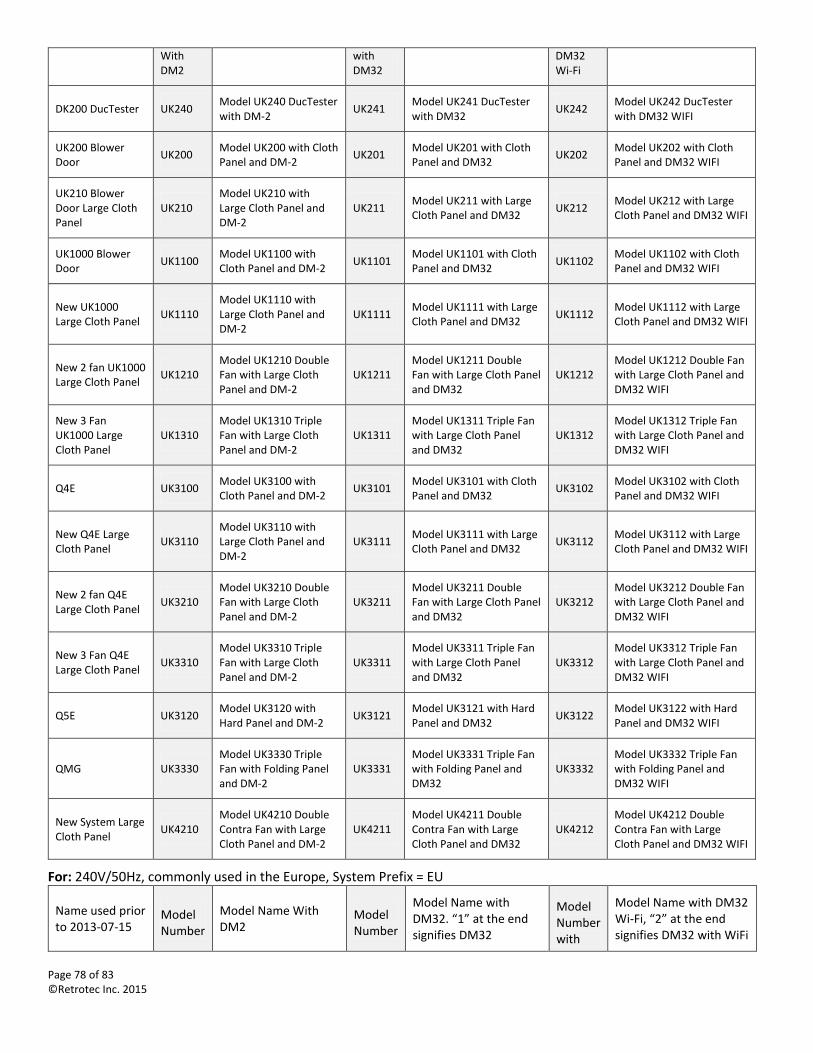
Page 78 of 83 ©Retrotec Inc. 2015
With DM2
with DM32
DM32 Wi-Fi
DK200 DucTester UK240 Model UK240 DucTester with DM-2
UK241 Model UK241 DucTester with DM32
UK242 Model UK242 DucTester with DM32 WIFI
UK200 Blower Door
UK200 Model UK200 with Cloth Panel and DM-2
UK201 Model UK201 with Cloth Panel and DM32
UK202 Model UK202 with Cloth Panel and DM32 WIFI
UK210 Blower Door Large Cloth Panel
UK210 Model UK210 with Large Cloth Panel and DM-2
UK211 Model UK211 with Large Cloth Panel and DM32
UK212 Model UK212 with Large Cloth Panel and DM32 WIFI
UK1000 Blower Door
UK1100 Model UK1100 with Cloth Panel and DM-2
UK1101 Model UK1101 with Cloth Panel and DM32
UK1102 Model UK1102 with Cloth Panel and DM32 WIFI
New UK1000 Large Cloth Panel
UK1110 Model UK1110 with Large Cloth Panel and DM-2
UK1111 Model UK1111 with Large Cloth Panel and DM32
UK1112 Model UK1112 with Large Cloth Panel and DM32 WIFI
New 2 fan UK1000 Large Cloth Panel
UK1210 Model UK1210 Double Fan with Large Cloth Panel and DM-2
UK1211 Model UK1211 Double Fan with Large Cloth Panel and DM32
UK1212 Model UK1212 Double Fan with Large Cloth Panel and DM32 WIFI
New 3 Fan UK1000 Large Cloth Panel
UK1310 Model UK1310 Triple Fan with Large Cloth Panel and DM-2
UK1311 Model UK1311 Triple Fan with Large Cloth Panel and DM32
UK1312 Model UK1312 Triple Fan with Large Cloth Panel and DM32 WIFI
Q4E UK3100 Model UK3100 with Cloth Panel and DM-2
UK3101 Model UK3101 with Cloth Panel and DM32
UK3102 Model UK3102 with Cloth Panel and DM32 WIFI
New Q4E Large Cloth Panel
UK3110 Model UK3110 with Large Cloth Panel and DM-2
UK3111 Model UK3111 with Large Cloth Panel and DM32
UK3112 Model UK3112 with Large Cloth Panel and DM32 WIFI
New 2 fan Q4E Large Cloth Panel
UK3210 Model UK3210 Double Fan with Large Cloth Panel and DM-2
UK3211 Model UK3211 Double Fan with Large Cloth Panel and DM32
UK3212 Model UK3212 Double Fan with Large Cloth Panel and DM32 WIFI
New 3 Fan Q4E Large Cloth Panel
UK3310 Model UK3310 Triple Fan with Large Cloth Panel and DM-2
UK3311 Model UK3311 Triple Fan with Large Cloth Panel and DM32
UK3312 Model UK3312 Triple Fan with Large Cloth Panel and DM32 WIFI
Q5E UK3120 Model UK3120 with Hard Panel and DM-2
UK3121 Model UK3121 with Hard Panel and DM32
UK3122 Model UK3122 with Hard Panel and DM32 WIFI
QMG UK3330 Model UK3330 Triple Fan with Folding Panel and DM-2
UK3331 Model UK3331 Triple Fan with Folding Panel and DM32
UK3332 Model UK3332 Triple Fan with Folding Panel and DM32 WIFI
New System Large Cloth Panel
UK4210 Model UK4210 Double Contra Fan with Large Cloth Panel and DM-2
UK4211 Model UK4211 Double Contra Fan with Large Cloth Panel and DM32
UK4212 Model UK4212 Double Contra Fan with Large Cloth Panel and DM32 WIFI
For: 240V/50Hz, commonly used in the Europe, System Prefix = EU
Name used prior to 2013-07-15
Model Number
Model Name With DM2
Model Number
Model Name with DM32. “1” at the end signifies DM32
Model Number with
Model Name with DM32 Wi-Fi, “2” at the end signifies DM32 with WiFi
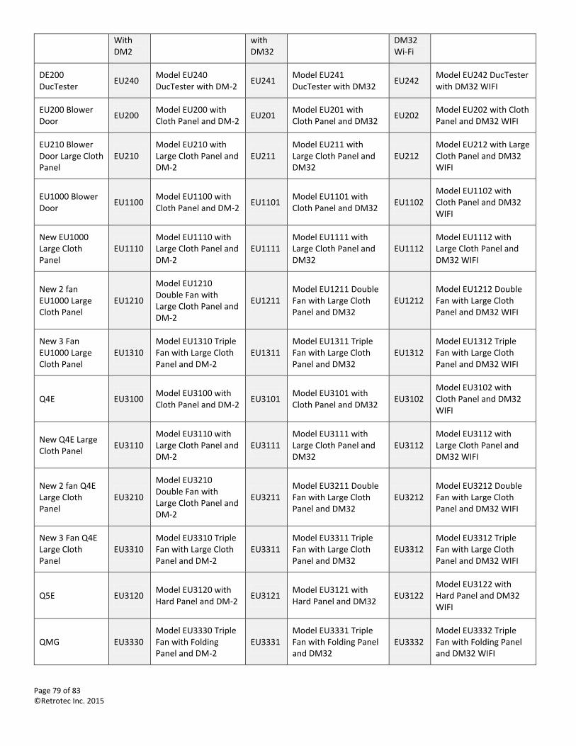
Page 79 of 83 ©Retrotec Inc. 2015
With DM2
with DM32
DM32 Wi-Fi
DE200 DucTester
EU240 Model EU240 DucTester with DM-2
EU241 Model EU241 DucTester with DM32
EU242 Model EU242 DucTester with DM32 WIFI
EU200 Blower Door
EU200 Model EU200 with Cloth Panel and DM-2
EU201 Model EU201 with Cloth Panel and DM32
EU202 Model EU202 with Cloth Panel and DM32 WIFI
EU210 Blower Door Large Cloth Panel
EU210 Model EU210 with Large Cloth Panel and DM-2
EU211 Model EU211 with Large Cloth Panel and DM32
EU212 Model EU212 with Large Cloth Panel and DM32 WIFI
EU1000 Blower Door
EU1100 Model EU1100 with Cloth Panel and DM-2
EU1101 Model EU1101 with Cloth Panel and DM32
EU1102 Model EU1102 with Cloth Panel and DM32 WIFI
New EU1000 Large Cloth Panel
EU1110 Model EU1110 with Large Cloth Panel and DM-2
EU1111 Model EU1111 with Large Cloth Panel and DM32
EU1112 Model EU1112 with Large Cloth Panel and DM32 WIFI
New 2 fan EU1000 Large Cloth Panel
EU1210
Model EU1210 Double Fan with Large Cloth Panel and DM-2
EU1211 Model EU1211 Double Fan with Large Cloth Panel and DM32
EU1212 Model EU1212 Double Fan with Large Cloth Panel and DM32 WIFI
New 3 Fan EU1000 Large Cloth Panel
EU1310 Model EU1310 Triple Fan with Large Cloth Panel and DM-2
EU1311 Model EU1311 Triple Fan with Large Cloth Panel and DM32
EU1312 Model EU1312 Triple Fan with Large Cloth Panel and DM32 WIFI
Q4E EU3100 Model EU3100 with Cloth Panel and DM-2
EU3101 Model EU3101 with Cloth Panel and DM32
EU3102 Model EU3102 with Cloth Panel and DM32 WIFI
New Q4E Large Cloth Panel
EU3110 Model EU3110 with Large Cloth Panel and DM-2
EU3111 Model EU3111 with Large Cloth Panel and DM32
EU3112 Model EU3112 with Large Cloth Panel and DM32 WIFI
New 2 fan Q4E Large Cloth Panel
EU3210
Model EU3210 Double Fan with Large Cloth Panel and DM-2
EU3211 Model EU3211 Double Fan with Large Cloth Panel and DM32
EU3212 Model EU3212 Double Fan with Large Cloth Panel and DM32 WIFI
New 3 Fan Q4E Large Cloth Panel
EU3310 Model EU3310 Triple Fan with Large Cloth Panel and DM-2
EU3311 Model EU3311 Triple Fan with Large Cloth Panel and DM32
EU3312 Model EU3312 Triple Fan with Large Cloth Panel and DM32 WIFI
Q5E EU3120 Model EU3120 with Hard Panel and DM-2
EU3121 Model EU3121 with Hard Panel and DM32
EU3122 Model EU3122 with Hard Panel and DM32 WIFI
QMG EU3330 Model EU3330 Triple Fan with Folding Panel and DM-2
EU3331 Model EU3331 Triple Fan with Folding Panel and DM32
EU3332 Model EU3332 Triple Fan with Folding Panel and DM32 WIFI
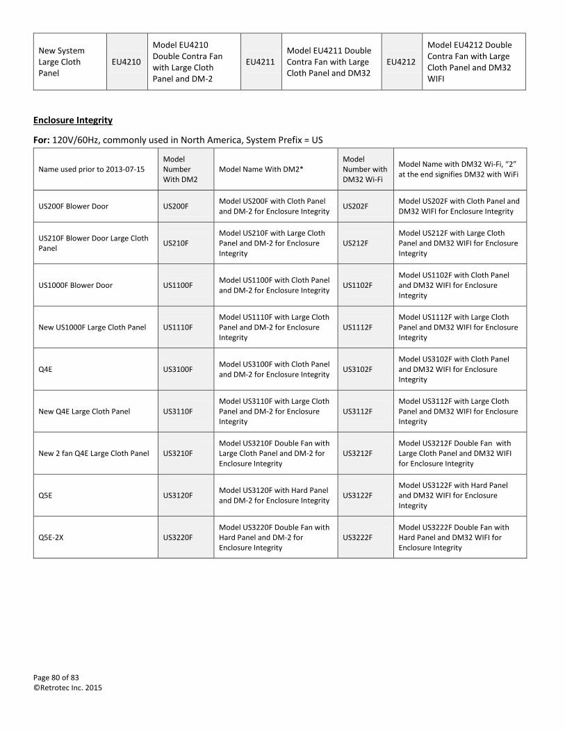
Page 80 of 83 ©Retrotec Inc. 2015
New System Large Cloth Panel
EU4210
Model EU4210 Double Contra Fan with Large Cloth Panel and DM-2
EU4211 Model EU4211 Double Contra Fan with Large Cloth Panel and DM32
EU4212
Model EU4212 Double Contra Fan with Large Cloth Panel and DM32 WIFI
Enclosure Integrity
For: 120V/60Hz, commonly used in North America, System Prefix = US
Name used prior to 2013-07-15 Model Number With DM2
Model Name With DM2* Model Number with DM32 Wi-Fi
Model Name with DM32 Wi-Fi, “2” at the end signifies DM32 with WiFi
US200F Blower Door US200F Model US200F with Cloth Panel and DM-2 for Enclosure Integrity
US202F Model US202F with Cloth Panel and DM32 WIFI for Enclosure Integrity
US210F Blower Door Large Cloth Panel
US210F Model US210F with Large Cloth Panel and DM-2 for Enclosure Integrity
US212F Model US212F with Large Cloth Panel and DM32 WIFI for Enclosure Integrity
US1000F Blower Door US1100F Model US1100F with Cloth Panel and DM-2 for Enclosure Integrity
US1102F Model US1102F with Cloth Panel and DM32 WIFI for Enclosure Integrity
New US1000F Large Cloth Panel US1110F Model US1110F with Large Cloth Panel and DM-2 for Enclosure Integrity
US1112F Model US1112F with Large Cloth Panel and DM32 WIFI for Enclosure Integrity
Q4E US3100F Model US3100F with Cloth Panel and DM-2 for Enclosure Integrity
US3102F Model US3102F with Cloth Panel and DM32 WIFI for Enclosure Integrity
New Q4E Large Cloth Panel US3110F Model US3110F with Large Cloth Panel and DM-2 for Enclosure Integrity
US3112F Model US3112F with Large Cloth Panel and DM32 WIFI for Enclosure Integrity
New 2 fan Q4E Large Cloth Panel US3210F Model US3210F Double Fan with Large Cloth Panel and DM-2 for Enclosure Integrity
US3212F Model US3212F Double Fan with Large Cloth Panel and DM32 WIFI for Enclosure Integrity
Q5E US3120F Model US3120F with Hard Panel and DM-2 for Enclosure Integrity
US3122F Model US3122F with Hard Panel and DM32 WIFI for Enclosure Integrity
Q5E-2X US3220F Model US3220F Double Fan with Hard Panel and DM-2 for Enclosure Integrity
US3222F Model US3222F Double Fan with Hard Panel and DM32 WIFI for Enclosure Integrity
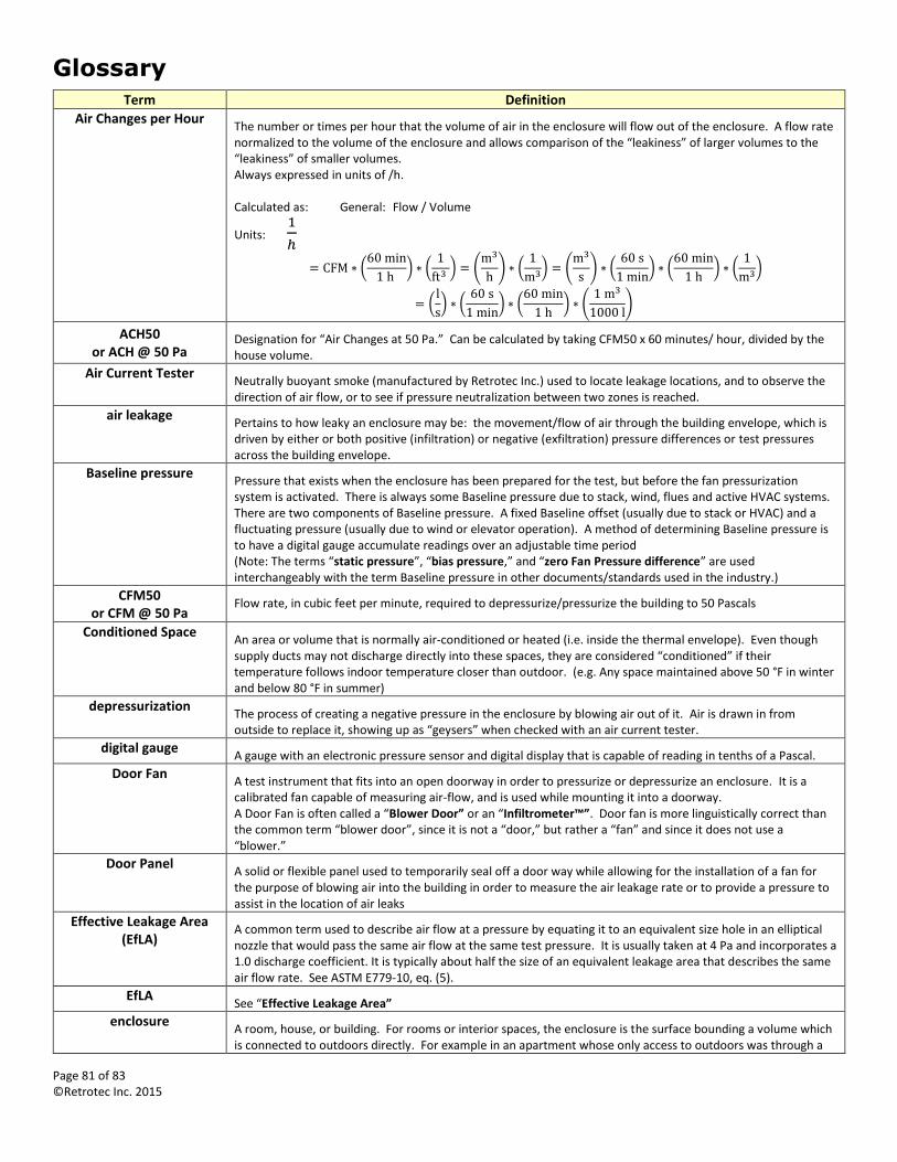
Page 81 of 83 ©Retrotec Inc. 2015
Glossary Term Definition
Air Changes per Hour The number or times per hour that the volume of air in the enclosure will flow out of the enclosure. A flow rate normalized to the volume of the enclosure and allows comparison of the “leakiness” of larger volumes to the “leakiness” of smaller volumes. Always expressed in units of /h. Calculated as: General: Flow / Volume
Units: 1
ℎ
= CFM ∗ (60 min
1 h ) ∗ (
1
ft3 ) = (
m3
h) ∗ (
1
m3) = (
m3
s) ∗ (
60 s
1 min) ∗ (
60 min
1 h) ∗ (
1
m3)
= (l
s) ∗ (
60 s
1 min) ∗ (
60 min
1 h) ∗ (
1 m3
1000 l)
ACH50 or ACH @ 50 Pa
Designation for “Air Changes at 50 Pa.” Can be calculated by taking CFM50 x 60 minutes/ hour, divided by the house volume.
Air Current Tester Neutrally buoyant smoke (manufactured by Retrotec Inc.) used to locate leakage locations, and to observe the direction of air flow, or to see if pressure neutralization between two zones is reached.
air leakage Pertains to how leaky an enclosure may be: the movement/flow of air through the building envelope, which is driven by either or both positive (infiltration) or negative (exfiltration) pressure differences or test pressures across the building envelope.
Baseline pressure Pressure that exists when the enclosure has been prepared for the test, but before the fan pressurization system is activated. There is always some Baseline pressure due to stack, wind, flues and active HVAC systems. There are two components of Baseline pressure. A fixed Baseline offset (usually due to stack or HVAC) and a fluctuating pressure (usually due to wind or elevator operation). A method of determining Baseline pressure is to have a digital gauge accumulate readings over an adjustable time period (Note: The terms “static pressure”, “bias pressure,” and “zero Fan Pressure difference” are used interchangeably with the term Baseline pressure in other documents/standards used in the industry.)
CFM50 or CFM @ 50 Pa
Flow rate, in cubic feet per minute, required to depressurize/pressurize the building to 50 Pascals
Conditioned Space An area or volume that is normally air-conditioned or heated (i.e. inside the thermal envelope). Even though supply ducts may not discharge directly into these spaces, they are considered “conditioned” if their temperature follows indoor temperature closer than outdoor. (e.g. Any space maintained above 50 °F in winter and below 80 °F in summer)
depressurization The process of creating a negative pressure in the enclosure by blowing air out of it. Air is drawn in from outside to replace it, showing up as “geysers” when checked with an air current tester.
digital gauge A gauge with an electronic pressure sensor and digital display that is capable of reading in tenths of a Pascal.
Door Fan A test instrument that fits into an open doorway in order to pressurize or depressurize an enclosure. It is a calibrated fan capable of measuring air-flow, and is used while mounting it into a doorway. A Door Fan is often called a “Blower Door” or an “Infiltrometer™”. Door fan is more linguistically correct than the common term “blower door”, since it is not a “door,” but rather a “fan” and since it does not use a “blower.”
Door Panel A solid or flexible panel used to temporarily seal off a door way while allowing for the installation of a fan for the purpose of blowing air into the building in order to measure the air leakage rate or to provide a pressure to assist in the location of air leaks
Effective Leakage Area (EfLA)
A common term used to describe air flow at a pressure by equating it to an equivalent size hole in an elliptical nozzle that would pass the same air flow at the same test pressure. It is usually taken at 4 Pa and incorporates a 1.0 discharge coefficient. It is typically about half the size of an equivalent leakage area that describes the same air flow rate. See ASTM E779-10, eq. (5).
EfLA See “Effective Leakage Area”
enclosure A room, house, or building. For rooms or interior spaces, the enclosure is the surface bounding a volume which is connected to outdoors directly. For example in an apartment whose only access to outdoors was through a
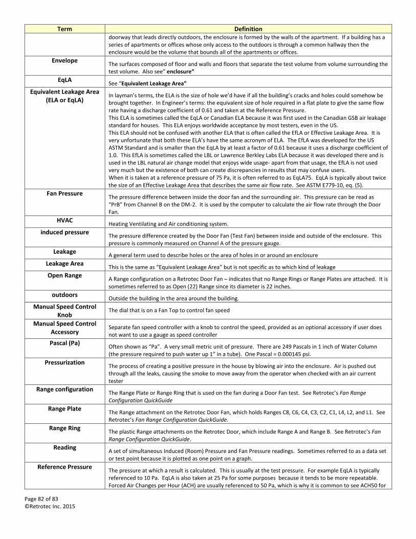
Page 82 of 83 ©Retrotec Inc. 2015
Term Definition doorway that leads directly outdoors, the enclosure is formed by the walls of the apartment. If a building has a series of apartments or offices whose only access to the outdoors is through a common hallway then the enclosure would be the volume that bounds all of the apartments or offices.
Envelope The surfaces composed of floor and walls and floors that separate the test volume from volume surrounding the test volume. Also see” enclosure”
EqLA See “Equivalent Leakage Area”
Equivalent Leakage Area (ELA or EqLA)
In layman’s terms, the ELA is the size of hole we’d have if all the building’s cracks and holes could somehow be brought together. In Engineer’s terms: the equivalent size of hole required in a flat plate to give the same flow rate having a discharge coefficient of 0.61 and taken at the Reference Pressure. This ELA is sometimes called the EqLA or Canadian ELA because it was first used in the Canadian GSB air leakage standard for houses. This ELA enjoys worldwide acceptance by most testers, even in the US. This ELA should not be confused with another ELA that is often called the EfLA or Effective Leakage Area. It is very unfortunate that both these ELA’s have the same acronym of ELA. The EfLA was developed for the US ASTM Standard and is smaller than the EqLA by at least a factor of 0.61 because it uses a discharge coefficient of 1.0. This EfLA is sometimes called the LBL or Lawrence Berkley Labs ELA because it was developed there and is used in the LBL natural air change model that enjoys wide usage- apart from that usage, the EfLA is not used very much but the existence of both can create discrepancies in results that may confuse users. When it is taken at a reference pressure of 75 Pa, it is often referred to as EqLA75. EqLA is typically about twice the size of an Effective Leakage Area that describes the same air flow rate. See ASTM E779-10, eq. (5).
Fan Pressure The pressure difference between inside the door fan and the surrounding air. This pressure can be read as “PrB” from Channel B on the DM-2. It is used by the computer to calculate the air flow rate through the Door Fan.
HVAC Heating Ventilating and Air conditioning system.
induced pressure The pressure difference created by the Door Fan (Test Fan) between inside and outside of the enclosure. This pressure is commonly measured on Channel A of the pressure gauge.
Leakage A general term used to describe holes or the area of holes in or around an enclosure
Leakage Area This is the same as “Equivalent Leakage Area” but is not specific as to which kind of leakage
Open Range A Range configuration on a Retrotec Door Fan – indicates that no Range Rings or Range Plates are attached. It is sometimes referred to as Open (22) Range since its diameter is 22 inches.
outdoors Outside the building in the area around the building.
Manual Speed Control Knob
The dial that is on a Fan Top to control fan speed
Manual Speed Control Accessory
Separate fan speed controller with a knob to control the speed, provided as an optional accessory if user does not want to use a gauge as speed controller
Pascal (Pa) Often shown as “Pa”. A very small metric unit of pressure. There are 249 Pascals in 1 inch of Water Column (the pressure required to push water up 1” in a tube). One Pascal = 0.000145 psi.
Pressurization The process of creating a positive pressure in the house by blowing air into the enclosure. Air is pushed out through all the leaks, causing the smoke to move away from the operator when checked with an air current tester
Range configuration The Range Plate or Range Ring that is used on the fan during a Door Fan test. See Retrotec’s Fan Range Configuration QuickGuide
Range Plate The Range attachment on the Retrotec Door Fan, which holds Ranges C8, C6, C4, C3, C2, C1, L4, L2, and L1. See Retrotec’s Fan Range Configuration QuickGuide.
Range Ring The plastic Range attachments on the Retrotec Door, which include Range A and Range B. See Retrotec’s Fan Range Configuration QuickGuide.
Reading A set of simultaneous Induced (Room) Pressure and Fan Pressure readings. Sometimes referred to as a data set or test point because it is plotted as one point on a graph.
Reference Pressure The pressure at which a result is calculated. This is usually at the test pressure. For example EqLA is typically referenced to 10 Pa. EqLA is also taken at 25 Pa for some purposes because it tends to be more repeatable. Forced Air Changes per Hour (ACH) are usually referenced to 50 Pa, which is why it is common to see ACH50 for
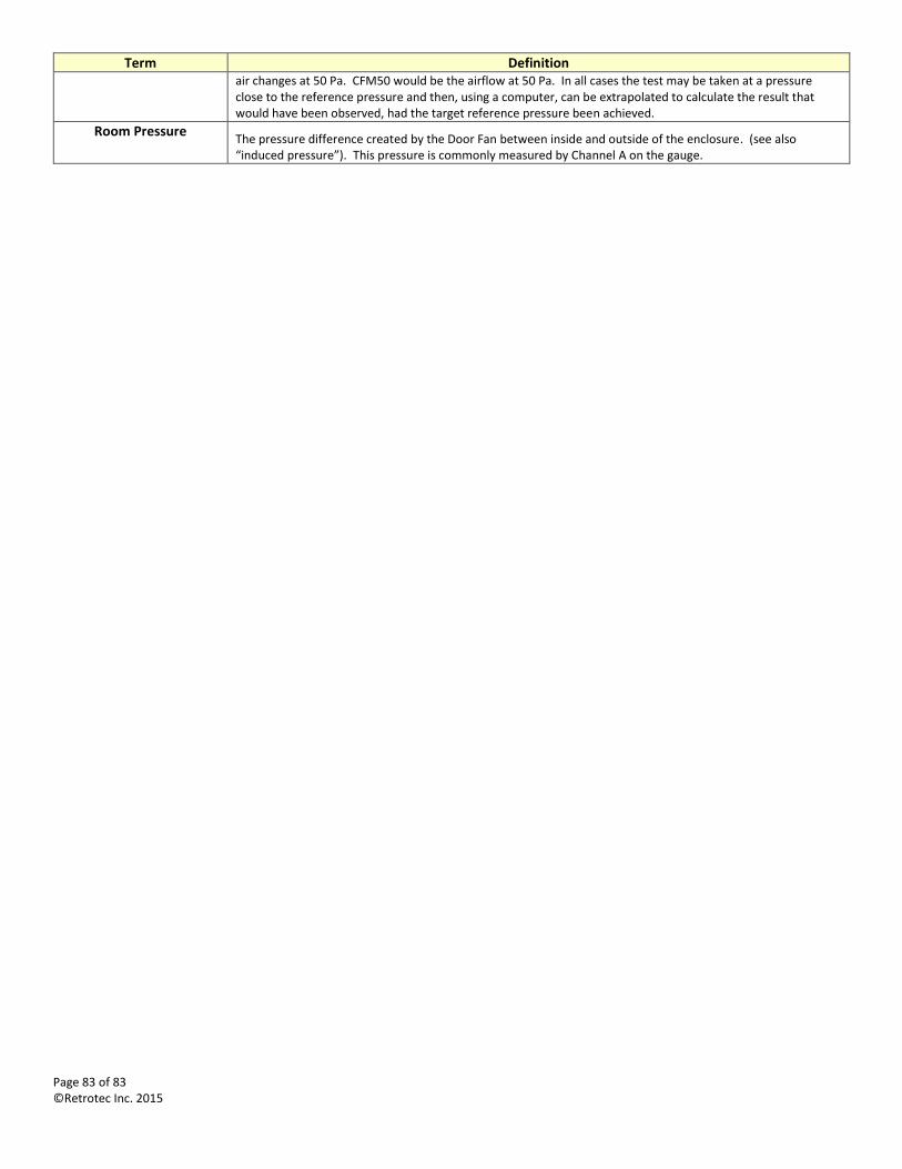
Page 83 of 83 ©Retrotec Inc. 2015
Term Definition air changes at 50 Pa. CFM50 would be the airflow at 50 Pa. In all cases the test may be taken at a pressure close to the reference pressure and then, using a computer, can be extrapolated to calculate the result that would have been observed, had the target reference pressure been achieved.
Room Pressure The pressure difference created by the Door Fan between inside and outside of the enclosure. (see also “induced pressure”). This pressure is commonly measured by Channel A on the gauge.