bit inspection technology - bitndtindia
TRANSCRIPT

BIT Inspection Technology
(NDT/ Weld Inspection Training / Consultancy/ Flaw Specimen Manufacturer)
Technical Justification Doc. no. BIT/TJ/ 002
1. Abstract
This Technical Note evaluates the practical possibilities of achieving “The density of the radiograph anywhere through the area of interest shall not vary by more than minus 15% or plus 30% from the density through the body of the designated hole-type IQI adjacent to the essential hole or adjacent to the essential wire of a wire-type IQI”. Refer, ASME Sec. V, para. T-282.2
2. Weld Sample Details
Size of weld sample - 300mm (length) x 300mm (width) x 12.4mm (Thick) Material - Carbon Steel Welding Process - GTAW / SMAW
3. Code Reference used
ASME Section V
AWS D1.1: 2015
ASME B 31.3, High Pressure Piping - Table K341.3.2
4. Weld Profile
Weld reinforcement allowed by Code for Visual Inspection of 12.4mm wall thickness groove weld in butt joint
0.5mm
2.2 mm

Cap Side:
Parameter AWS D1.1: 2015
ASME B 31.3, High Pressure Piping - Table K341.3.2
Actual reinforcement in the sample
Cap reinforcement height in mm 3 3 2.2
Root reinforcement height in mm 3 3 0.5
No cap weld reinforcement
Cap weld reinforcement
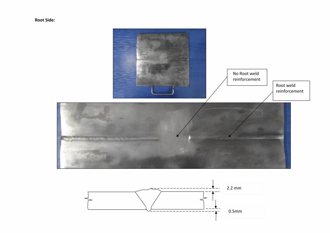
Root Side:
Root weld reinforcement
No Root weld reinforcement
0.5mm
2.2 mm
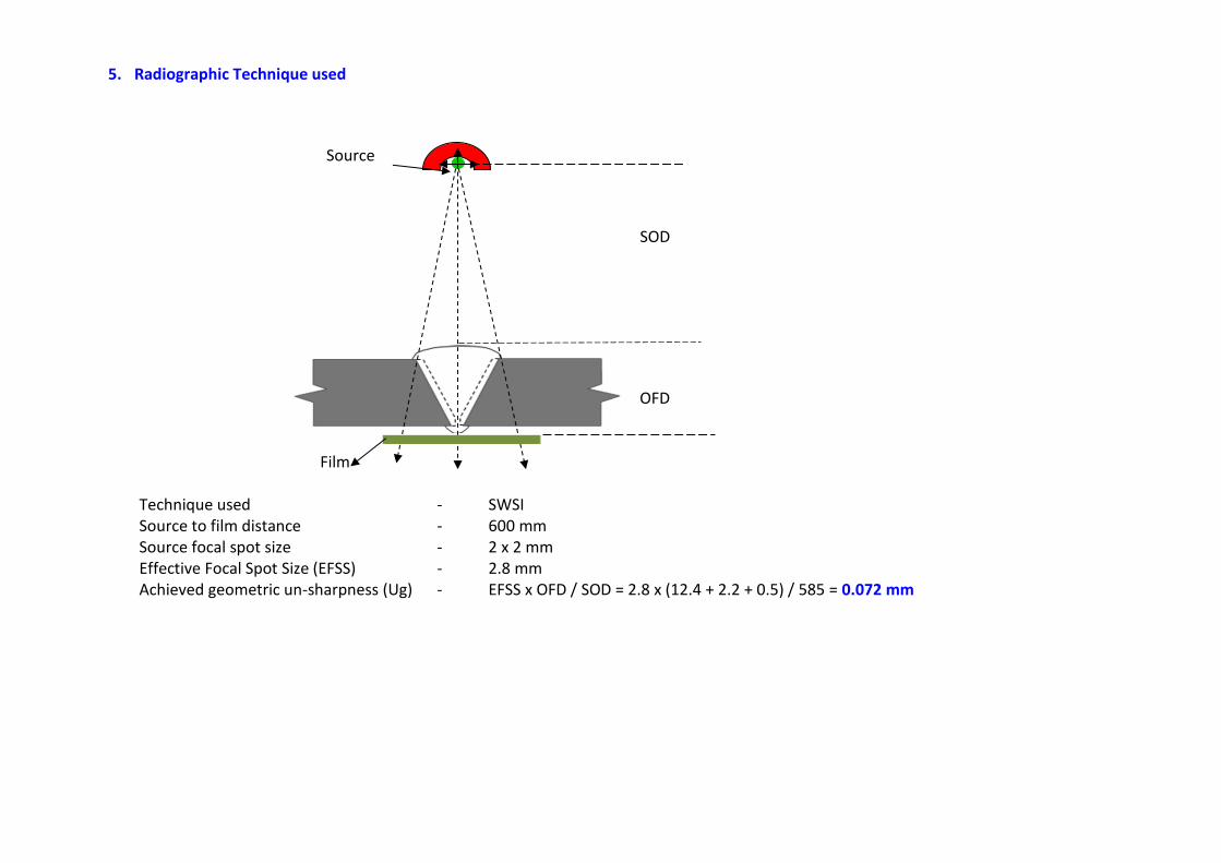
5. Radiographic Technique used
Source
SOD
OFD Film
Technique used - SWSI Source to film distance - 600 mm Source focal spot size - 2 x 2 mm Effective Focal Spot Size (EFSS) - 2.8 mm Achieved geometric un-sharpness (Ug) - EFSS x OFD / SOD = 2.8 x (12.4 + 2.2 + 0.5) / 585 = 0.072 mm

6. Radiographic Film Image of Sample used Film Type - Kodak AA400 Size - 300 mm x 80 mm
40 mm 75 mm 140 mm 228 mm
Cap + Root + base metal Thickness Image
Root + base metal thickness Image
Base metal thickness Image only
Cluster Porosity
Root Crack
Side Wall Lack of Fusion

7. Radiographic Density Measurement (Range) B
Root + base metal Thickness Image only
Cap + Root + base metal thickness Image
Cap + Root + base metal Thickness Image
Root + base metal thickness Image
Cap + Root + base metal Thickness Image
1.88 - 1.94 2.66 - 2.69 2.06 - 2.23 2.84 - 2.86
2.67 - 2.71
2.06 - 2.20
2.80 - 2.84
Base metal Thickness Image only
2.77 - 2.79

8. Densitometer
Model - Optel - Trans - 4V Sr. No. - J-3233
9. Sensitivity Achieved
5th wire clearly visible in 10 FE DIN, IQI set = 0.16 mm
Penetrated thickness = Base metal thickness + Cap reinforcement + Root reinforcement = 12.4 + 2.2 + 0.5
% of Sensitivity Achieved = 0.16 / (12.4 + 2.2 + 0.5) x 100 = 1.06% 10. Intended Defect Detectability
Type of defect intended in the Sample Specimen
Status of detection
Cluster Porosity Detected
Root Crack Detected
Side Wall of Fusion Detected

11. Radiographic Density Measurement (Average)
1
2.78
2
3
2.15
4
5 2.69
6 8
2.82
2.13
7
1.91 2.68 2.85

Note - 1: Ref. Point: The location of the radiograph (weld with root and cap) at adjacent to the essential wire of a wire-type IQI. % of density
variation calculated reference to this point. Note - 2: Considered all the possibilities of weld metal deposit during manufacturing which were influences density variation, for example
Weld metal fill without excess weld deposit at both side root & cap (Location 5 simulates). In general, possibilities are expected due to internal concavity with coincidence of weld metal filled just up to the base metal thickness at cap side.
Weld metal fill up to base metal thickness at cap side (without cap reinforcement) - Location 3 & 6 simulates
Note - 3: Very often major density variation expected between center of the weld and parent material (HAZ), as shown in the below sketch due to excess weld metal at cap and root.
Location Density
Measurement
Density variation in % with reference to the Ref. Point
Remarks
1 Weld with root and cap reinforcement 1.91 - 10.3 %
2 HAZ (Parent Metal) 2.78 + 30.5 % Note - 3
3 Weld with root reinforcement and without cap reinforcement 2.68 + 25.8 % Note - 2
4 Weld with root and cap reinforcement 2.15 + 0.94 %
5 Weld without root and cap reinforcement 2.85 + 33.8 % Note - 2
6 Weld with root reinforcement and without cap reinforcement 2.69 + 26.3 % Note - 2
7 Ref. point (Note -1) - Weld with root and cap reinforcement 2.13 0
8 HAZ (Parent Metal) 2.82 + 32.4 % Note - 3
2.2 mm
0.5mm
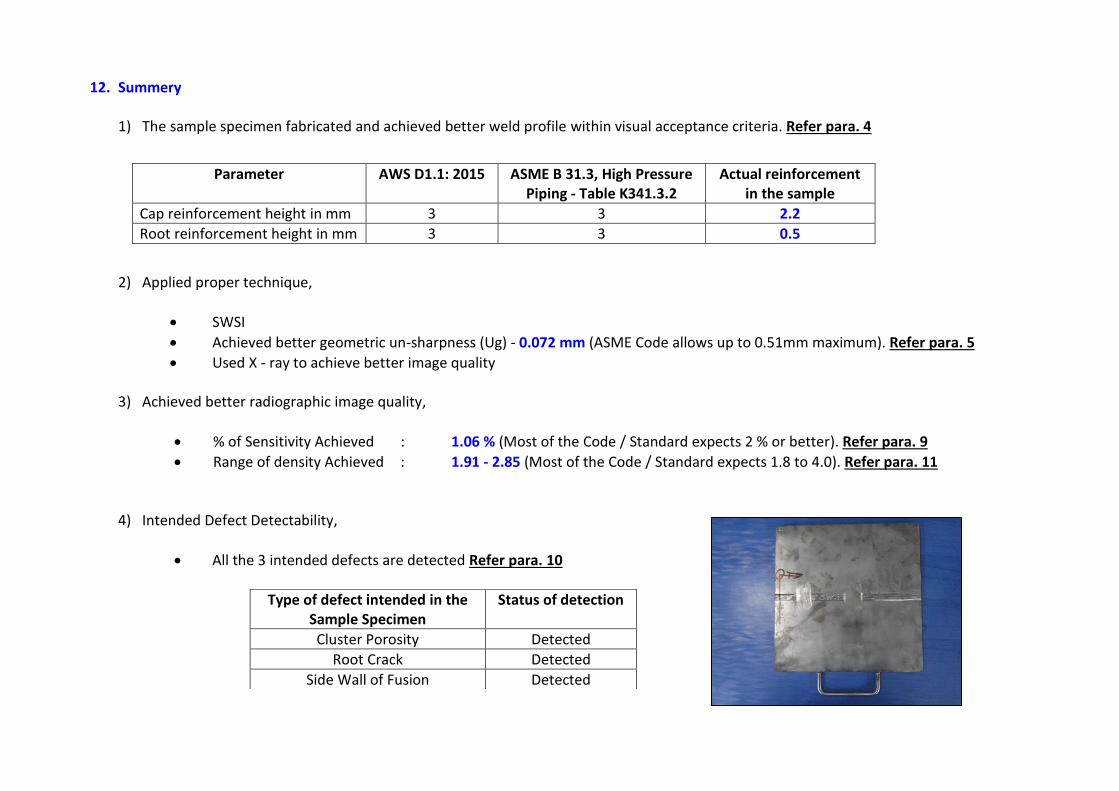
12. Summery
1) The sample specimen fabricated and achieved better weld profile within visual acceptance criteria. Refer para. 4
2) Applied proper technique,
SWSI
Achieved better geometric un-sharpness (Ug) - 0.072 mm (ASME Code allows up to 0.51mm maximum). Refer para. 5
Used X - ray to achieve better image quality
3) Achieved better radiographic image quality,
% of Sensitivity Achieved : 1.06 % (Most of the Code / Standard expects 2 % or better). Refer para. 9
Range of density Achieved : 1.91 - 2.85 (Most of the Code / Standard expects 1.8 to 4.0). Refer para. 11
4) Intended Defect Detectability,
All the 3 intended defects are detected Refer para. 10
Parameter AWS D1.1: 2015
ASME B 31.3, High Pressure Piping - Table K341.3.2
Actual reinforcement in the sample
Cap reinforcement height in mm 3 3 2.2
Root reinforcement height in mm 3 3 0.5
Type of defect intended in the Sample Specimen
Status of detection
Cluster Porosity Detected
Root Crack Detected
Side Wall of Fusion Detected

13. Practical Difficulties to achieve density variation within limit specified in the Code
Even though after applied stringent fabrication / radiographic technique and achieved better image quality, but failed to achieve density variation within limit due to area of interest covers wide range of location, which were influence variation in radiographic density due to absorption difference between base metal and weld with both cap & root reinforcement.
This difficulties faced particularly in X-ray radiograph, because of higher contrast image achievable by X-ray.
This difficulties will further raised if the components are curved, for example piping radiograph involved particularly with DWSI and DWDI techniques.
In general, this difficulties are not much in Gamma –ray radiograph, because of lesser contrast image achievable by gamma -ray
14. Recommendation When this practical difficulties exist due to,
Fabrication difficulties like weld reinforcement height achieved at higher side of acceptable range
Curvature effect of component, which results density variation
If above inherent difficulties are exist and difficult to avoid, then try with Proper Exposure Technique like selection of optimized energy level (Kv) should be balanced between required contrast (absorption difference) and latitude (covering wide range of thickness in the single exposure).
Practical difficulties to be studied properly and raised through Technical Note and justify the case in front of Client. In this case, recommended to
Compare the density variation along the same absorption thickness, as shown in the image in next page for both base metal and weld metal.
Range of radiographic density shall be between 2.0 to 3.0 for Base Metal (HAZ)

For Weld Metal: For Base Metal:
Ref. Point
Ref. Point

Evaluated by R.Baskar, AMIE (Mech) Technical Director PCN Co-ordinator BIT Inspection Technology Pvt Ltd, BINDT's ATO & AQB for PCN scheme ASNT NDT Level III RT, UT, PT, MT, VT, ET PCN NDT Level III UT, PT, MT, RT / Level II RI ISO 9712 NDT level 3 III UT, RT, VT (Multi-sector) CSWIP 3.2 / AWS - SCWI + 91 9840800863 / + 91 44 42720054 [email protected], www.bitndtindia.com