biomechanics why the seahorse tail is squaremeyersgroup.ucsd.edu/papers/journals/meyers 399.pdf ·...
TRANSCRIPT
RESEARCH ARTICLE SUMMARY◥
BIOMECHANICS
Why the seahorse tail is squareMichael M. Porter,* Dominique Adriaens,Ross L. Hatton, Marc A. Meyers, Joanna McKittrick
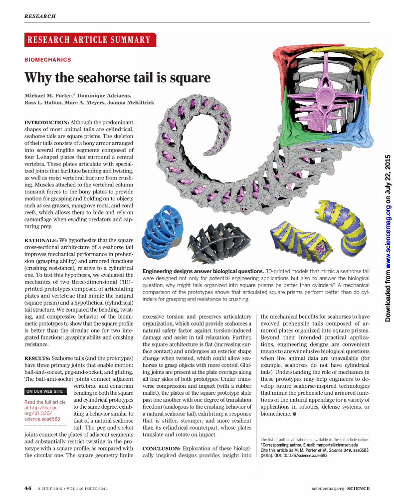
INTRODUCTION: Although the predominantshapes of most animal tails are cylindrical,seahorse tails are square prisms. The skeletonof their tails consists of a bony armor arrangedinto several ringlike segments composed offour L-shaped plates that surround a centralvertebra. These plates articulate with special-ized joints that facilitate bending and twisting,as well as resist vertebral fracture from crush-ing. Muscles attached to the vertebral columntransmit forces to the bony plates to providemotion for grasping and holding on to objectssuch as sea grasses, mangrove roots, and coralreefs, which allows them to hide and rely oncamouflage when evading predators and cap-turing prey.
RATIONALE:We hypothesize that the squarecross-sectional architecture of a seahorse tailimproves mechanical performance in prehen-sion (grasping ability) and armored functions(crushing resistance), relative to a cylindricalone. To test this hypothesis, we evaluated themechanics of two three-dimensional (3D)–printed prototypes composed of articulatingplates and vertebrae that mimic the natural(square prism) and a hypothetical (cylindrical)tail structure.We compared the bending, twist-ing, and compressive behavior of the biomi-metic prototypes to show that the square profileis better than the circular one for two inte-grated functions: grasping ability and crushingresistance.
RESULTS: Seahorse tails (and the prototypes)have three primary joints that enable motion:ball-and-socket, peg-and-socket, and gliding.The ball-and-socket joints connect adjacent
vertebrae and constrainbending inboth the squareand cylindrical prototypesto the same degree, exhib-iting a behavior similar tothat of a natural seahorsetail. The peg-and-socket
joints connect the plates of adjacent segmentsand substantially restrict twisting in the pro-totype with a square profile, as compared withthe circular one. The square geometry limits
excessive torsion and preserves articulatoryorganization, which could provide seahorses anatural safety factor against torsion-induceddamage and assist in tail relaxation. Further,the square architecture is flat (increasing sur-face contact) and undergoes an exterior shapechange when twisted, which could allow sea-horses to grasp objects with more control. Glid-ing joints are present at the plate overlaps alongall four sides of both prototypes. Under trans-verse compression and impact (with a rubbermallet), the plates of the square prototype slidepast one another with one degree of translationfreedom (analogous to the crushing behavior ofa natural seahorse tail), exhibiting a responsethat is stiffer, stronger, and more resilientthan its cylindrical counterpart, whose platestranslate and rotate on impact.
CONCLUSION: Exploration of these biologi-cally inspired designs provides insight into
the mechanical benefits for seahorses to haveevolved prehensile tails composed of ar-mored plates organized into square prisms.Beyond their intended practical applica-tions, engineering designs are convenientmeans to answer elusive biological questionswhen live animal data are unavailable (forexample, seahorses do not have cylindricaltails). Understanding the role of mechanics inthese prototypes may help engineers to de-velop future seahorse-inspired technologiesthatmimic the prehensile and armored func-tions of the natural appendage for a variety ofapplications in robotics, defense systems, orbiomedicine.▪
RESEARCH
46 3 JULY 2015 • VOL 349 ISSUE 6243 sciencemag.org SCIENCE
The list of author affiliations is available in the full article online.*Corresponding author. E-mail: [email protected] this article as M. M. Porter et al., Science 349, aaa6683(2015). DOI: 10.1126/science.aaa6683
Engineering designs answer biological questions. 3D-printed models that mimic a seahorse tailwere designed not only for potential engineering applications but also to answer the biologicalquestion, why might tails organized into square prisms be better than cylinders? A mechanicalcomparison of the prototypes shows that articulated square prisms perform better than do cyl-inders for grasping and resistance to crushing.
RESEARCH ARTICLE SUMMARY◥
ON OUR WEB SITE◥
Read the full articleat http://dx.doi.org/10.1126/science.aaa6683..................................................
on
July
22,
201
5w
ww
.sci
ence
mag
.org
Dow
nloa
ded
from
o
n Ju
ly 2
2, 2
015
ww
w.s
cien
cem
ag.o
rgD
ownl
oade
d fr
om
on
July
22,
201
5w
ww
.sci
ence
mag
.org
Dow
nloa
ded
from
o
n Ju
ly 2
2, 2
015
ww
w.s
cien
cem
ag.o
rgD
ownl
oade
d fr
om
on
July
22,
201
5w
ww
.sci
ence
mag
.org
Dow
nloa
ded
from
o
n Ju
ly 2
2, 2
015
ww
w.s
cien
cem
ag.o
rgD
ownl
oade
d fr
om
on
July
22,
201
5w
ww
.sci
ence
mag
.org
Dow
nloa
ded
from
o
n Ju
ly 2
2, 2
015
ww
w.s
cien
cem
ag.o
rgD
ownl
oade
d fr
om
RESEARCH ARTICLE◥
BIOMECHANICS
Why the seahorse tail is squareMichael M. Porter,1* Dominique Adriaens,2 Ross L. Hatton,3
Marc A. Meyers,4,5,6 Joanna McKittrick4,5
Whereas the predominant shapes of most animal tails are cylindrical, seahorse tails aresquare prisms. Seahorses use their tails as flexible grasping appendages, in spite of arigid bony armor that fully encases their bodies. We explore the mechanics of twothree-dimensional–printed models that mimic either the natural (square prism) orhypothetical (cylindrical) architecture of a seahorse tail to uncover whether or not thesquare geometry provides any functional advantages. Our results show that the squareprism is more resilient when crushed and provides a mechanism for preserving articulatoryorganization upon extensive bending and twisting, as compared with its cylindricalcounterpart. Thus, the square architecture is better than the circular one in the contextof two integrated functions: grasping ability and crushing resistance.
Seahorses do not use their tails for swim-ming because they lack a caudal fin (1), butinstead as flexible prehensile appendagesthat allow them to hide and rely on bodycrypsis to evade predators (2) and capture
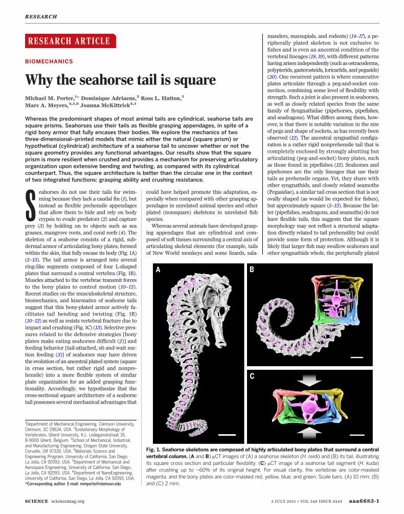
prey (3) by holding on to objects such as seagrasses, mangrove roots, and coral reefs (4). Theskeleton of a seahorse consists of a rigid, sub-dermal armor of articulating bony plates, formedwithin the skin, that fully encase its body (Fig. 1A)(5–13). The tail armor is arranged into severalring-like segments composed of four L-shapedplates that surround a central vertebra (Fig. 1B).Muscles attached to the vertebrae transmit forcesto the bony plates to control motion (10–12).Recent studies on the musculoskeletal structure,biomechanics, and kinematics of seahorse tailssuggest that this bony-plated armor actively fa-cilitates tail bending and twisting (Fig. 1B)(10–12) as well as resists vertebral fracture due toimpact and crushing (Fig. 1C) (13). Selective pres-sures related to the defensive strategies [bonyplates make eating seahorses difficult (2)] andfeeding behavior [tail-attached, sit-and-wait suc-tion feeding (3)] of seahorses may have driventhe evolution of an ancestral plated system (squarein cross section, but rather rigid and nonpre-hensile) into a more flexible system of similarplate organization for an added grasping func-tionality. Accordingly, we hypothesize that thecross-sectional square architecture of a seahorsetail possesses severalmechanical advantages that
could have helped promote this adaptation, es-pecially when compared with other grasping ap-pendages in unrelated animal species and otherplated (nonsquare) skeletons in unrelated fishspecies.Whereas several animals have developed grasp-
ing appendages that are cylindrical and com-posed of soft tissues surrounding a central axis ofarticulating skeletal elements (for example, tailsof New World monkeys and some lizards, sala-
manders, marsupials, and rodents) (14–17), a pe-ripherally plated skeleton is not exclusive tofishes and is even an ancestral condition of thevertebral lineages (18, 19), with different patternshavingarisen independently (suchasostracoderms,polypterids, gasterosteids, loricariids, andpegasids)(20). One recurrent pattern is where consecutiveplates articulate through a peg-and-socket con-nection, combining some level of flexibility withstrength. Such a joint is also present in seahorses,as well as closely related species from the samefamily of Syngnathidae (pipehorses, pipefishes,and seadragons). What differs among them, how-ever, is that there is notable variation in the sizeof pegs and shape of sockets, as has recently beenobserved (12). The ancestral syngnathid configu-ration is a rather rigid nonprehensile tail that iscompletely enclosed by strongly abutting butarticulating (peg-and-socket) bony plates, suchas those found in pipefishes (12). Seahorses andpipehorses are the only lineages that use theirtails as prehensile organs. Yet, they share withother syngnathids, and closely related seamoths(Pegasidae), a similar tail cross section that is notovally shaped (as would be expected for fishes),but approximately square (5–13). Because the lat-ter (pipefishes, seadragons, and seamoths) do nothave flexible tails, this suggests that the squaremorphology may not reflect a structural adapta-tion directly related to tail prehensility but couldprovide some form of protection. Although it islikely that larger fish may swallow seahorses andother syngnathids whole, the peripherally plated
RESEARCH
SCIENCE sciencemag.org 3 JULY 2015 • VOL 349 ISSUE 6243 aaa6683-1
1Department of Mechanical Engineering, Clemson University,Clemson, SC 29634, USA. 2Evolutionary Morphology ofVertebrates, Ghent University, K.L. Ledeganckstraat 35,B-9000 Ghent, Belgium. 3School of Mechanical, Industrial,and Manufacturing Engineering, Oregon State University,Corvallis, OR 97330, USA. 4Materials Science andEngineering Program, University of California, San Diego,La Jolla, CA 92093, USA. 5Department of Mechanical andAerospace Engineering, University of California, San Diego,La Jolla, CA 92093, USA. 6Department of NanoEngineering,University of California, San Diego, La Jolla, CA 92093, USA.*Corresponding author. E-mail: [email protected]
Fig. 1. Seahorse skeletons are composed of highly articulated bony plates that surround a centralvertebral column. (A and B) mCT images of (A) a seahorse skeleton (H. reidi) and (B) its tail, illustratingits square cross section and particular flexibility. (C) mCT image of a seahorse tail segment (H. kuda)after crushing up to ~60% of its original height. For visual clarity, the vertebrae are color-maskedmagenta, and the bony plates are color-masked red, yellow, blue, and green. Scale bars, (A) 10 mm; (B)and (C) 2 mm.
skeleton can protect their soft tissues againstbites from smaller predators (13). In the case ofpipefishes, which closely resemble the syngnathidancestral state, fortifying the body as a poorlybendable “stick” makes them difficult prey toswallow and digest (2). Also, their second largestgroup of predators (next to teleosts) are water-birds, with waders and seabirds accounting for32% of all syngnathid predators (2). Becausemanybirds use beaks to clamp down and capture preybefore feeding, it is likely that the skeletal armorcould protect seahorses from crushing (13).Whena seahorse tail is crushed, for instance, the bonyplates slide past one another, acting as an energyabsorption mechanism, which resists fracture ofthe vertebral column (Fig. 1C) (13). This is differ-ent from the mechanisms observed in the skinand scales of other fish that provide an optimalflexural stiffness for both swimming and protec-tion against predatory attacks (21–23). Hence,this complex skeletal systemmay provide seahorsesan advantageous combination of joint flexibilityfor prehensionwith shielding fromexternal forcesfor protection.Similar to recent works that used robots to
investigate animal behavior and locomotion(24, 25), we used three-dimensional (3D)–printedmodels to explore the mechanics of seahorsetails. Because cylindrical seahorse tails do notexist in nature, 3D printing allows us to buildfunctional models of this hypothetical systemso as to investigate what mechanical advantagesan articulated square prism may have over a cyl-inder, which is the common shape of most otheranimal tails. This falsifiable methodology isparticularly useful to examine the mechanicsof musculoskeletal systems in vertebrates thatare difficult or impossible to study in nature(for example, seahorses do not have cylindricaltails). Thus, via 3D printing we replicated com-parativemodels thatmimic the specialized jointsand complex morphologies of both the natural(square prism) and hypothetical (cylindrical)systems.
In a quest to better understand armored pre-hensility in seahorses and develop useful toolsinspired by their tails, we designed this new classof highly articulated structures—not only for bio-logical research, but also for a wide range of po-tential robotics, armored systems, and biomedicalapplications. Such applications for the seahorse-inspired technology would be able to take advan-tage of a large body of kinematics and actuationwork that has been developed for similar long,slender “continuum” structures inspired by or-ganisms such as snakes and worms (26–30),squids and octopuses (tentacles) (31, 32), ele-phants (trunks) (33), and plants (tendrils androots) (34, 35). The combination of articulatedrigid plates and elastic deformability observed ina seahorse tail (Fig. 1) could strike a promising bal-ance between the two dominant paradigms in ro-botics design: being lighter and more compliantthan traditional “hard” robots built from servosand metal, but more robust and resistant to ex-ternal tractions than the emerging class of “soft”robots with silicone-membrane bodies. However,akin to nature, the vast majority of these seriallyarticulated structures (26–35) have cylindricalprofiles. Therefore, we ask the question, whymight square prisms be better than cylinders?
Inspired by seahorses, designedby engineers
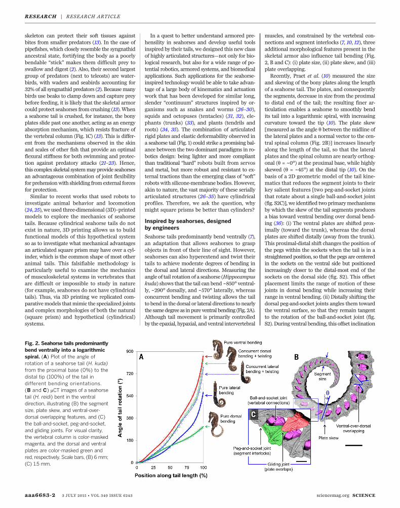
Seahorse tails predominantly bend ventrally (7),an adaptation that allows seahorses to graspobjects in front of their line of sight. However,seahorses can also hyperextend and twist theirtails to achieve moderate degrees of bending inthe dorsal and lateral directions. Measuring theangle of tail rotation of a seahorse (Hippocampuskuda) shows that the tail can bend ~850° ventral-ly, ~290° dorsally, and ~570° laterally, whereasconcurrent bending and twisting allows the tailto bend in the dorsal or lateral directions to nearlythe samedegree as inpure ventral bending (Fig. 2A).Although tail movement is primarily controlledby the epaxial, hypaxial, and ventral intervertebral
muscles, and constrained by the vertebral con-nections and segment interlocks (7, 10, 12), threeadditional morphological features present in theskeletal armor also influence tail bending (Fig.2, B and C): (i) plate size, (ii) plate skew, and (iii)plate overlapping.Recently, Praet et al. (10) measured the size
and skewing of the bony plates along the lengthof a seahorse tail. The plates, and consequentlythe segments, decrease in size from the proximalto distal end of the tail; the resulting finer ar-ticulation enables a seahorse to smoothly bendits tail into a logarithmic spiral, with increasingcurvature toward the tip (10). The plate skew[measured as the angle q between the midline ofthe lateral plates and a normal vector to the cen-tral spinal column (Fig. 2B)] increases linearlyalong the length of the tail, so that the lateralplates and the spinal column are nearly orthog-onal (q = ~0°) at the proximal base, while highlyskewed (q = ~45°) at the distal tip (10). On thebasis of a 2D geometric model of the tail kine-matics that reduces the segment joints to theirkey salient features [two peg-and-socket jointsthat rotate about a single ball-and-socket joint(fig. S2C)], we identified twoprimarymechanismsby which the skew of the tail segments producesa bias toward ventral bending over dorsal bend-ing (36): (i) The ventral plates are shifted prox-imally (toward the trunk), whereas the dorsalplates are shifted distally (away from the trunk).This proximal-distal shift changes the position ofthe pegs within the sockets when the tail is in astraightened position, so that the pegs are centeredin the sockets on the ventral side but positionedincreasingly closer to the distal-most end of thesockets on the dorsal side (fig. S2). This offsetplacement limits the range of motion of thesejoints in dorsal bending while increasing theirrange in ventral bending. (ii) Distally shifting thedorsal peg-and-socket joints angles them towardthe ventral surface, so that they remain tangentto the rotation of the ball-and-socket joint (fig.S2). During ventral bending, this offset inclination
aaa6683-2 3 JULY 2015 • VOL 349 ISSUE 6243 sciencemag.org SCIENCE
Fig. 2. Seahorse tails predominantlybend ventrally into a logarithmicspiral. (A) Plot of the angle ofrotation of a seahorse tail (H. kuda)from the proximal base (0%) to thedistal tip (100%) of the tail indifferent bending orientations.(B and C) mCT images of a seahorsetail (H. reidi) bent in the ventraldirection, illustrating (B) the segmentsize, plate skew, and ventral-over-dorsal overlapping features, and (C)the ball-and-socket, peg-and-socket,and gliding joints. For visual clarity,the vertebral column is color-maskedmagenta, and the dorsal and ventralplates are color-masked green andred, respectively. Scale bars, (B) 6mm;(C) 1.5 mm.
RESEARCH | RESEARCH ARTICLE
allows the sockets of the distal plates to lie flushwith the pegs of the proximal plates on the dorsalside of the tail, instead of “peeling” away at thesejoints. These two mechanisms both increase therange of motion of the joints in the ventral direc-tion, producing the different sagittal (ventro-dorsal)bend angles observed in Fig. 2A, and improve thealignment of adjacent plates when the tail is in acurledposition (Fig. 2B). Further, itwas previouslynoted that the ventral plates always overlap thedorsal plates along the lateral sides of the tail (Fig.2B) (13). This bisymmetric ventral-over-dorsal over-lapping arrangement likely promotes ventral tailbending as well (fig. S3), so that the ventral plateshave more freedom to slide and rotate, and hencemore articulation space, because they are not rig-idly attached to the vertebral column [as in thecase of the dorsal plates (7, 10)]. Consequently, wehypothesize that eliminating all of these morpho-logical features (plate size, skew, and ventral-over-
dorsal overlaps) from the skeletal armor of a sea-horse would allow its tail to bend equally in alldirections (ignoring the effect of muscular orien-tation and connective tissue composition).To test this hypothesis, we designed and built
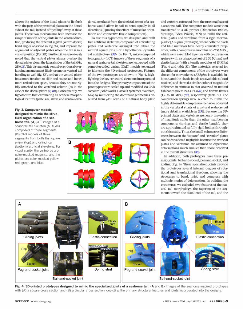
two artificial skeletons composed of articulatingplates and vertebrae arranged into either thenatural square prism or a hypothetical cylindri-cal architecture (36). In Fig. 3, microcomputedtomography (mCT) images of three segments of anatural seahorse tail skeleton are juxtaposed withcomputer-aided design (CAD) models generatedto fabricate the 3D-printed prototypes. Picturesof the two prototypes are shown in Fig. 4, high-lighting the key structural elements incorporatedinto the designs. The primary components of theprototypes were scaled up andmodified via CADsoftware (SolidWorks, Dassault Systemes,Waltham,MA) by mimicking the dominant geometries ob-served from mCT scans of a natural bony plate
and vertebra extracted from the proximal base ofa seahorse tail. The computer models were thentransferred to a 3D printer (Dimension 1200es,Stratasys, Eden Prairie, MN) to build the arti-ficial plates and vertebrae from a rigid thermo-plastic [ABSplus (Stratasys), where both the blackand blue materials have nearly equivalent prop-erties, with a compressive modulus of ~700MPa],whichwere assembled together with compressionsprings (with a spring constant of 3.36N/mm) andelastic bands (with a tensile modulus of 15 MPa)(Fig. 4 and table S1). The materials selected forthe different components of the prototypes werechosen for convenience (ABSplus is available in-house, and the elastic bands are available at localretailers) and showed a similar order-of-magnitudedifference in stiffness to that observed in naturalfish bones (3.5 to 19.4 GPa) (37) and fibrous tissues(1.2 to 10 MPa) (37), respectively (table S1). Thecompression springs were selected to mimic thehighly deformable compressive behavior observedin the vertebral struts of a natural seahorse tail[more detail is available in (13)]. Because the 3D-printed plates and vertebrae are nearly two ordersof magnitude stiffer than the other load-bearingcomponents (springs and elastic bands), theyare approximated as fully rigid bodies through-out this study. Thus, the small volumetric differ-ences between the “square” and “circular” platescan be considered negligible because the artificialplates and vertebrae are assumed to experiencedeformations much smaller than those observedin the overall structures (36).In addition, both prototypes have three pri-
mary joints: ball-and-socket, peg-and-socket, andgliding (Fig. 4). These specialized joints providethe prototypes several internal degrees of rota-tional and translational freedom, allowing thestructures to bend, twist, and compress withmultiple modes of deformation. In building theprototypes, we excluded two features of the nat-ural tail morphology: the tapering of the seg-ments toward the distal end of the tail, and the
SCIENCE sciencemag.org 3 JULY 2015 • VOL 349 ISSUE 6243 aaa6683-3
Fig. 3. Computer modelsdesigned to mimic the struc-tural organization of a sea-horse tail. (A) mCT images of aseahorse tail skeleton (H. kuda)composed of three segments.(B) CAD models of threesegments from both the squareprism (top) and cylindrical(bottom) artificial skeletons. Forvisual clarity, the vertebrae arecolor-masked magenta, and theplates are color-masked yellow,red, green, and blue.
Fig. 4. 3D-printed prototypes designed to mimic the specialized joints of a seahorse tail. (A and B) Images of the seahorse-inspired prototypeswith (A) a square cross section and (B) a circular cross section, depicting the primary structural features and joints incorporated into the designs.
RESEARCH | RESEARCH ARTICLE
skewing of the segments. This simplification fo-cuses attention on the cross-sectional structureof the plates. The tapering is relatively small[<5% size difference between adjacent links nearthe proximal base (10)] and allows the tail to graspsmall objects (10, 11). Similarly, the change insegment skew is relatively small (~2° to 3°angular difference between adjacent links) andcan be accounted for in the tail’s bias towardventral bending (fig. S2). If we had incorporatedthe segment skew in our model, we anticipatethat the resulting offset between the ventral anddorsal plates would have provided a small in-crease to the crushing resistance of the proto-types (by spreading loads applied to a ventralplate across two dorsal plates, and vice versa). Thesequence of intrasegmental connections (plateoverlaps) in the prototypes was asymmetricallyalternated, so that each alternating segment con-tains right-over-left overlaps, followed by left-over-right overlaps, along the central midlines,eliminating the regular ventral-over-dorsal over-lapping arrangement observed in the naturaltail. These design modifications produced aquadraxial symmetry in both prototypes, whichas hypothesized facilitates equal bending in allthree directions (ventral, dorsal, and lateral).
Bending, twisting, and prehension
The images and CAD models of the squareprismatic and cylindrical prototypes shown inFig. 5 illustrate the limits of bending and twist-ing, which would likely change by altering thesize and skewing of the plates (36). If the platesare bisymmetrically overlapped to more closelymimic the natural configuration, the prototypesfavor bending in the “ventral” direction, whichwas confirmed via experimental observations(fig. S3). Regardless, for comparative purposes,
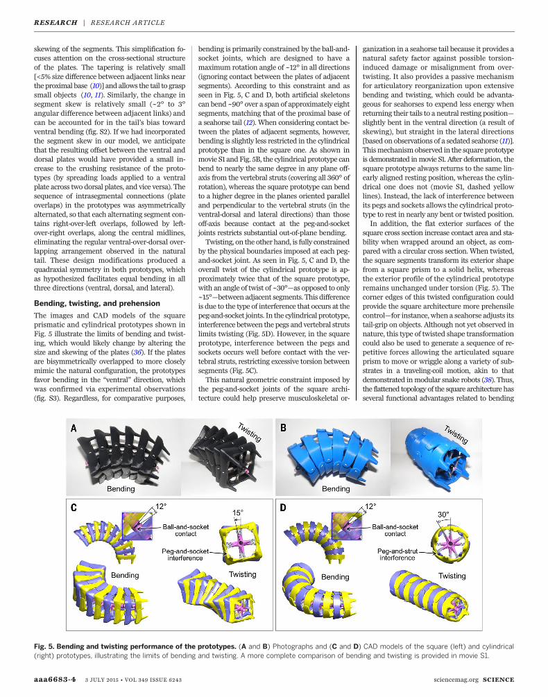
bending is primarily constrained by the ball-and-socket joints, which are designed to have amaximum rotation angle of ~12° in all directions(ignoring contact between the plates of adjacentsegments). According to this constraint and asseen in Fig. 5, C and D, both artificial skeletonscan bend ~90° over a span of approximately eightsegments, matching that of the proximal base ofa seahorse tail (12). When considering contact be-tween the plates of adjacent segments, however,bending is slightly less restricted in the cylindricalprototype than in the square one. As shown inmovie S1 andFig. 5B, the cylindrical prototype canbend to nearly the same degree in any plane off-axis from the vertebral struts (covering all 360° ofrotation), whereas the square prototype can bendto a higher degree in the planes oriented paralleland perpendicular to the vertebral struts (in theventral-dorsal and lateral directions) than thoseoff-axis because contact at the peg-and-socketjoints restricts substantial out-of-plane bending.Twisting, on the other hand, is fully constrained
by the physical boundaries imposed at each peg-and-socket joint. As seen in Fig. 5, C and D, theoverall twist of the cylindrical prototype is ap-proximately twice that of the square prototype,with an angle of twist of ~30°—as opposed to only~15°—between adjacent segments. This differenceis due to the type of interference that occurs at thepeg-and-socket joints. In the cylindrical prototype,interference between the pegs and vertebral strutslimits twisting (Fig. 5D). However, in the squareprototype, interference between the pegs andsockets occurs well before contact with the ver-tebral struts, restricting excessive torsion betweensegments (Fig. 5C).This natural geometric constraint imposed by
the peg-and-socket joints of the square archi-tecture could help preserve musculoskeletal or-
ganization in a seahorse tail because it provides anatural safety factor against possible torsion-induced damage or misalignment from over-twisting. It also provides a passive mechanismfor articulatory reorganization upon extensivebending and twisting, which could be advanta-geous for seahorses to expend less energy whenreturning their tails to a neutral resting position—slightly bent in the ventral direction (a result ofskewing), but straight in the lateral directions[based on observations of a sedated seahorse (11)].Thismechanismobserved in the square prototypeis demonstrated inmovie S1. After deformation, thesquare prototype always returns to the same lin-early aligned resting position, whereas the cylin-drical one does not (movie S1, dashed yellowlines). Instead, the lack of interference betweenits pegs and sockets allows the cylindrical proto-type to rest in nearly any bent or twisted position.In addition, the flat exterior surfaces of the
square cross section increase contact area and sta-bility when wrapped around an object, as com-pared with a circular cross section. When twisted,the square segments transform its exterior shapefrom a square prism to a solid helix, whereasthe exterior profile of the cylindrical prototyperemains unchanged under torsion (Fig. 5). Thecorner edges of this twisted configuration couldprovide the square architecture more prehensilecontrol—for instance, when a seahorse adjusts itstail-grip on objects. Although not yet observed innature, this type of twisted shape transformationcould also be used to generate a sequence of re-petitive forces allowing the articulated squareprism to move or wriggle along a variety of sub-strates in a traveling-coil motion, akin to thatdemonstrated inmodular snake robots (38). Thus,the flattened topology of the square architecture hasseveral functional advantages related to bending
aaa6683-4 3 JULY 2015 • VOL 349 ISSUE 6243 sciencemag.org SCIENCE
Fig. 5. Bending and twisting performance of the prototypes. (A and B) Photographs and (C and D) CAD models of the square (left) and cylindrical(right) prototypes, illustrating the limits of bending and twisting. A more complete comparison of bending and twisting is provided in movie S1.
RESEARCH | RESEARCH ARTICLE
and twisting that could allow seahorses to graspobjects with more control.
Impact, crushing, and protection
Beyond simple bending and twisting, the artifi-cial skeletons also mimic the protective energyabsorption mechanism observed in the highly de-formable skeleton of a seahorse tail (Fig. 1C) (13).When subject to impact, such as the compressiveforce of a rubber mallet (Fig. 6, A and B, andmovie S2), the gliding joints and vertebral strutsof the prototypes allow the plates to slide pastone another (or rotate, in the case of the cylin-drical prototype), absorb the impact when com-pressed, and subsequently protect the internalvertebral column from brittle fracture. As seen inmovie S2, the square prototype returns to its lin-early aligned resting position after impact, whereasthe cylindrical one remains partially deformed andmisaligned (even when the first and last segmentsare taped to the supporting plane). Although thereis some plate rotation observed in segments of thesquare prototype adjacent to the primary impactpoint, the plates directly impacted mainly showlinear sliding. In contrast, the cylindrical proto-type experiences extreme reverberations trans-ferred through its vertebral column upon impact.Under ideal uniaxial compression, the artifi-
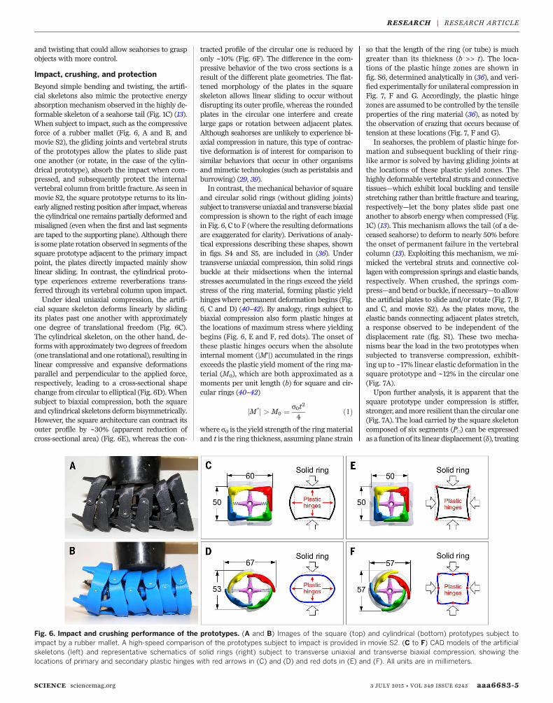
cial square skeleton deforms linearly by slidingits plates past one another with approximatelyone degree of translational freedom (Fig. 6C).The cylindrical skeleton, on the other hand, de-formswith approximately two degrees of freedom(one translational and one rotational), resulting inlinear compressive and expansive deformationsparallel and perpendicular to the applied force,respectively, leading to a cross-sectional shapechange from circular to elliptical (Fig. 6D). Whensubject to biaxial compression, both the squareand cylindrical skeletons deform bisymmetrically.However, the square architecture can contract itsouter profile by ~30% (apparent reduction ofcross-sectional area) (Fig. 6E), whereas the con-
tracted profile of the circular one is reduced byonly ~10% (Fig. 6F). The difference in the com-pressive behavior of the two cross sections is aresult of the different plate geometries. The flat-tened morphology of the plates in the squareskeleton allows linear sliding to occur withoutdisrupting its outer profile, whereas the roundedplates in the circular one interfere and createlarge gaps or rotation between adjacent plates.Although seahorses are unlikely to experience bi-axial compression in nature, this type of contrac-tive deformation is of interest for comparison tosimilar behaviors that occur in other organismsand mimetic technologies (such as peristalsis andburrowing) (29, 39).In contrast, the mechanical behavior of square
and circular solid rings (without gliding joints)subject to transverseuniaxial and transversebiaxialcompression is shown to the right of each imagein Fig. 6, C to F (where the resulting deformationsare exaggerated for clarity). Derivations of analy-tical expressions describing these shapes, shownin figs. S4 and S5, are included in (36). Undertransverse uniaxial compression, thin solid ringsbuckle at their midsections when the internalstresses accumulated in the rings exceed the yieldstress of the ring material, forming plastic yieldhinges where permanent deformation begins (Fig.6, C and D) (40–42). By analogy, rings subject tobiaxial compression also form plastic hinges atthe locations of maximum stress where yieldingbegins (Fig. 6, E and F, red dots). The onset ofthese plastic hinges occurs when the absoluteinternal moment (|M′|) accumulated in the ringsexceeds the plastic yield moment of the ring ma-terial (M0), which are both approximated as amoments per unit length (b) for square and cir-cular rings (40–42)
jM ′j > M0 ¼ s0t2
4ð1Þ
where s0 is the yield strength of the ringmaterialand t is the ring thickness, assuming plane strain
so that the length of the ring (or tube) is muchgreater than its thickness (b >> t). The loca-tions of the plastic hinge zones are shown infig. S6, determined analytically in (36), and veri-fied experimentally for unilateral compression inFig. 7, F and G. Accordingly, the plastic hingezones are assumed to be controlled by the tensileproperties of the ring material (36), as noted bythe observation of crazing that occurs because oftension at these locations (Fig. 7, F and G).In seahorses, the problem of plastic hinge for-
mation and subsequent buckling of their ring-like armor is solved by having gliding joints atthe locations of these plastic yield zones. Thehighly deformable vertebral struts and connectivetissues—which exhibit local buckling and tensilestretching rather than brittle fracture and tearing,respectively—let the bony plates slide past oneanother to absorb energy when compressed (Fig.1C) (13). This mechanism allows the tail (of a de-ceased seahorse) to deform to nearly 50% beforethe onset of permanent failure in the vertebralcolumn (13). Exploiting this mechanism, we mi-micked the vertebral struts and connective col-lagenwith compression springs and elastic bands,respectively. When crushed, the springs com-press—and bend or buckle, if necessary—to allowthe artificial plates to slide and/or rotate (Fig. 7, Band C, and movie S2). As the plates move, theelastic bands connecting adjacent plates stretch,a response observed to be independent of thedisplacement rate (fig. S1). These two mecha-nisms bear the load in the two prototypes whensubjected to transverse compression, exhibit-ing up to ~17% linear elastic deformation in thesquare prototype and ~12% in the circular one(Fig. 7A).Upon further analysis, it is apparent that the
square prototype under compression is stiffer,stronger, andmore resilient than the circular one(Fig. 7A). The load carried by the square skeletoncomposed of six segments (P□) can be expressedas a function of its linear displacement (d), treating
SCIENCE sciencemag.org 3 JULY 2015 • VOL 349 ISSUE 6243 aaa6683-5
Fig. 6. Impact and crushing performance of the prototypes. (A and B) Images of the square (top) and cylindrical (bottom) prototypes subject toimpact by a rubber mallet. A high-speed comparison of the prototypes subject to impact is provided in movie S2. (C to F) CAD models of the artificialskeletons (left) and representative schematics of solid rings (right) subject to transverse uniaxial and transverse biaxial compression, showing thelocations of primary and secondary plastic hinges with red arrows in (C) and (D) and red dots in (E) and (F). All units are in millimeters.
RESEARCH | RESEARCH ARTICLE
the 3D-printed plates and vertebrae as rigidbodies, so that
P□ ¼ 6� 1
2ks þ 6
bsL3s
þ 4ke
� �d ð2Þ
where ks = 3.36 N/mm is the compressive springconstant, bs = 2.0 × 10⁻⁴ N · m2 is the flexuralrigidity of the springs, Ls = 10 mm is the activelengthof the springs inbending, andke=0.20N/mmis the effective spring constant of the elastic bands(fig. S7) (36). Similarly, the load carried by thecylindrical skeleton composed of six segments(P○) can also be expressed as a function of itslinear displacement (d)
P○ ¼ 6� 1
4ksðdþ gÞ a
cþ kez
b
c
� �ð3Þ
where a, b, and c are geometric relations depen-dent on the radius of plate curvature (R= 30mm),
and (d + g) and z are the vertical and lateraldisplacements of the cylindrical skeleton, respec-tively (36). To account for the six segments in eachprototype compressed in parallel (Fig. 7, A to C),Eqs. 2 and 3 are both multiplied by a factor of six.A plot of these equations (dashed lines) is shown
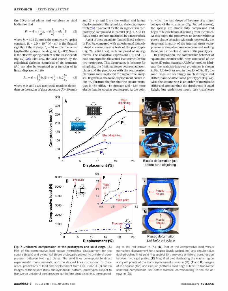
in Fig. 7A, compared with experimental data ob-tained via compression tests of the prototypes(Fig. 7A, solid lines), each composed of six seg-ments. The analytical expressions (P□ and P○)both underpredict the actual load carried by thetwo prototypes. This discrepancy is because forsimplicity, the frictional forces between adjacentplates and the prototypes with the compressionplatforms were neglected throughout the analy-ses. Regardless, the force-displacement curves inFig. 7A illustrate the fact that the square proto-type is ~3× stiffer, ~4× stronger, and ~1.5× moreelastic than its circular counterpart. At the point
at which the load drops off because of a minorcollapse of the structures (Fig. 7A, red arrows),the springs are almost fully compressed andbegin to buckle before disjoining from the plates.At this point, the prototypes no longer exhibit apurely elastic behavior. Although recoverable, thestructural integrity of the internal struts (com-pression springs) becomes compromised, makingthese points the elastic limits of the prototypes.In juxtaposition, the compressive behavior of
square and circular solid rings composed of thesame 3D-print material (ABSplus) used to fabri-cate the seahorse-inspired prototypes is shownin Fig. 7, D to G. As seen in the plot of Fig. 7D, thesolid rings are seemingly much stronger andstiffer than the articulated prototypes (Fig. 7A).Also, the square ring is an order of magnitudestiffer and stronger than the circular one of equalheight but undergoes much less transverse
aaa6683-6 3 JULY 2015 • VOL 349 ISSUE 6243 sciencemag.org SCIENCE
Fig. 7. Unilateral compression of the prototypes and solid rings. (A)Plot of the compressive load versus normalized displacement for thesquare (black) and cylindrical (blue) prototypes subject to unilateral com-pression between two rigid plates. The solid lines correspond to directexperimental measurements, and the dashed lines correspond to theo-retical predictions of load and displacement from Eqs. 2 and 3. (B and C)Images of the square (top) and cylindrical (bottom) prototypes subject totransverse unilateral compression just before strut disjoining, correspond-
ing to the red arrows in (A). (D) Plot of the compressive load versusnormalized displacement for a square (black dashed line) and circular (bluedashed-dotted line) solid ring subject to transverse unilateral compressionbetween two rigid plates. (E) Magnified plot illustrating the elastic regionand yield points of the load-displacement curves in (D). (F and G) Imagesof the square (top) and circular (bottom) solid rings subject to transverseunilateral compression just before fracture, corresponding to the red ar-rows in (D).
RESEARCH | RESEARCH ARTICLE
displacement before failure. Nevertheless, thesebehaviors (Fig. 7D) occur when the solid ringsare loaded within the plastic regime, beyond theinitial formation of plastic hinges [which beginat the yield point, the first sign of permanent de-formation (Fig. 7E)]. Considering this, it is moreuseful to compare the elastic behavior of thearticulated prototypes (Fig. 7A) with that of thesolid rings (Fig. 7E). As indicated in Fig. 7E, bothsolid rings begin to yield at ~30 N, whereas thesquare ring elastically deforms only ~0.1% andthe circular ring ~0.8%.When crushed, the squareprototype outperforms the cylindrical one, exhib-iting a higher strength and stiffness, analogousto themechanical performance of the solid rings.The square prototype is also more resilient thanthe cylindrical one, absorbing more energy be-fore failure (strut disjoining), a trend not observedin the solid rings (solid rings with circular crosssections are more resilient than square ones).Thus, the specialized joints present in the proto-types (and likewise in a seahorse tail) provide thestructures an enhanced range of motion, notonly in bending and twisting but also in resist-ance to crushing.
Concluding remarks
The highly articulated bony plates that surroundthe central vertebral axis of a seahorse tail ac-tively facilitate bending and twisting as well asresist vertebral fracture from impact and crush-ing. To explore why the bony plates are arrangedinto cross-sectional squares rather than circles,we analyzed themechanics of 3D-printedmodelsthat mimic the natural (square prism) and hypo-thetical (cylindrical) architectures of a seahorsetail skeleton. Physical manipulation of the twoprototypes revealed that the square architecturepossesses several mechanical advantages over itscircular counterpart in bending, twisting, and re-sistance to crushing. The enhanced performancerealized in the square architecture provides in-sight into the way in which seahorses may ben-efit from having prehensile tails composed ofarmored plates organized into square prisms,rather than cylinders. This study demonstratesthat engineering designs are convenientmeansto answer elusive biological questions when biol-ogical data are nonexistent or difficult to obtain.In addition, understanding the role ofmechanicsin these biologically inspired designs may helpengineers to develop seahorse-inspired technol-ogies for a variety of applications in robotics, de-fense systems, or biomedicine.
REFERENCES AND NOTES
1. M. A. Ashley-Ross, Mechanical properties of the dorsal finmuscle of seahorse (Hippocampus) and pipefish (Syngnathus).J. Exp. Zool. 293, 561–577 (2002). doi: 10.1002/jez.10183;pmid: 12410605
2. D. Kleiber, L. K. Blight, I. R. Caldwell, A. C. J. Vincent, Theimportance of seahorses and pipefishes in the diet of marineanimals. Rev. Fish Biol. Fish. 21, 205–223 (2011). doi: 10.1007/s11160-010-9167-5
3. S. Van Wassenbergh, G. Roos, L. Ferry, An adaptiveexplanation for the horse-like shape of seahorses. Nat.Commun. 2, 164 (2011). doi: 10.1038/ncomms1168;pmid: 21266964
4. S. A. Lourie, S. J. Foster, E. W. T. Cooper, A. C. J. Vincent,A Guide to the Identification of Seahorses (Project Seahorse,Washington, DC, 2004).
5. R. Anthony, L. Chevroton, Considérations sur les attitudes et lalocomotion de l’hippocampe, étude chronophotographique.Arch. Zool. Exp. Gen. 51, 11–22 (1913).
6. H. Peters, [On the ecologic physiology of the sea horse(Hippocampus brevirostris)]. Z. Vgl. Physiol. 33, 207–265(1951). doi: 10.1007/BF00395584; pmid: 24541372
7. M. E. Hale, Functional morphology of ventral tail bendingand prehensile abilities of the seahorse, Hippocampus kuda.J. Morphol. 227, 51–65 (1996). doi: 10.1002/(SICI)1097-4687(199601)227:1<51::AID-JMOR4>3.0.CO;2-S
8. E. Bruner, V. Bartolino, Morphological variation in the seahorsevertebral system. Int. J. Morphol. 26, 247–262 (2008).doi: 10.4067/S0717-95022008000200002
9. S. Van Cauter et al., Virtual design from nature: Kinematicmodeling of the seahorse tail. SIMULIA Customer Conference,770–783 (2010).
10. T. Praet et al., Inspiration from nature: Dynamic modelling ofthe musculoskeletal structure of the seahorse tail. Int. J.Numer. Method Biomed. Eng. 28, 1028–1042 (2012).doi: 10.1002/cnm.2499; pmid: 23027633
11. T. Praet, thesis, Ghent University, Ghent, Belgium (2013).12. C. Neutens et al., Grasping convergent evolution in
syngnathids: A unique tale of tails. J. Anat. 224, 710–723(2014). doi: 10.1111/joa.12181; pmid: 24697519
13. M. M. Porter, E. Novitskaya, A. B. Castro-Ceseña, M. A. Meyers,J. McKittrick, Highly deformable bones: Unusual deformationmechanisms of seahorse armor. Acta Biomater. 9, 6763–6770(2013). doi: 10.1016/j.actbio.2013.02.045; pmid: 23470547
14. G. C. Hickman, The mammalian tail: A review of functions.Mammal Rev. 9, 143–157 (1979). doi: 10.1111/j.1365-2907.1979.tb00252.x
15. L. Emmons, A. H. Gentry, Tropical forest structure and thedistribution of gliding and prehensile-tailed vertebrates.Am. Nat. 121, 513–524 (1983). doi: 10.1086/284079
16. K. C. Zippel, R. E. Glor, J. E. Bertram, On caudal prehensilityand phylogenetic constraint in lizards: The influence ofancestral anatomy on function in Corucia and Furcifer.J. Morphol. 239, 143–155 (1999). doi: 10.1002/(SICI)1097-4687(199902)239:2<143::AID-JMOR3>3.0.CO;2-O
17. J. M. Organ, V. B. Deleon, Q. Wang, T. D. Smith, From head totail: New models and approaches in primate functionalanatomy and biomechanics. Anat. Rec. 293, 544–548 (2010).doi: 10.1002/ar.21132; pmid: 20235310
18. J.-Y. Sire, A. Huysseune, Formation of dermal skeletal anddental tissues in fish: A comparative and evolutionaryapproach. Biol. Rev. Camb. Philos. Soc. 78, 219–249 (2003).doi: 10.1017/S1464793102006073; pmid: 12803422
19. P. C. J. Donoghue, I. J. Sansom, J. P. Downs, Early evolution ofvertebrate skeletal tissues and cellular interactions, and thecanalization of skeletal development. J. Exp. Zoolog. B Mol.Dev. Evol. 306, 278–294 (2006). doi: 10.1002/jez.b.21090;pmid: 16555304
20. J. S. Nelson, Fishes of the World (Wiley, New York, 2006).21. J. Long, M. Hale, M. Mchenry, M. Westneat, Functions of fish
skin: Flexural stiffness and steady swimming of longnose gar,Lepisosteus osseus. J. Exp. Biol. 199, 2139–2151 (1996).pmid: 9320050
22. B. J. F. Bruet, J. Song, M. C. Boyce, C. Ortiz, Materials designprinciples of ancient fish armour. Nat. Mater. 7, 748–756(2008). doi: 10.1038/nmat2231; pmid: 18660814
23. F. J. Vernerey, F. Barthelat, Skin and scales of teleost fish:Simple structure but high performance and multiple functions.J. Mech. Phys. Solids 68, 66–76 (2014). doi: 10.1016/j.jmps.2014.01.005
24. T. Libby et al., Tail-assisted pitch control in lizards, robots anddinosaurs. Nature 481, 181–184 (2012). doi: 10.1038/nature10710; pmid: 22217942
25. A. J. Ijspeert, Biorobotics: Using robots to emulate andinvestigate agile locomotion. Science 346, 196–203 (2014).doi: 10.1126/science.1254486; pmid: 25301621
26. K. Xu, N. Simaan, Actuation compensation for flexible surgicalsnake-like robots with redundant remote actuation. IEEEInternational Conference on Robotics and Automation,4148–4154 (2006).
27. C. Wright et al., Design of a modular snake robot. IEEE/RSJInternational Conference on Intelligent Robots and Systems(2007).
28. J. K. Hopkins, B. W. Spranklin, S. K. Gupta, A survey of snake-inspired robot designs. Bioinspir. Biomim. 4, 021001 (2009).doi: 10.1088/1748-3182/4/2/021001; pmid: 19158415
29. K. A. Daltorio et al., Efficient worm-like locomotion: Slip andcontrol of soft-bodied peristaltic robots. Bioinspir. Biomim. 8,035003 (2013). doi: 10.1088/1748-3182/8/3/035003;pmid: 23981561
30. C. D. Onal, R. J. Wood, D. Rus, An origami-inspired approach toworm robots. IEEE/ASME Trans. Mechatron. 18, 430–438(2013). doi: 10.1109/TMECH.2012.2210239
31. I. D. Walker et al., Continuum robot arms inspired bycephalopods. Conference on Unmanned Ground VehicleTechnology VII 5804, 303–314 (2005).
32. R. F. Shepherd et al., Multigait soft robot. Proc. Natl. Acad. Sci.U.S.A. 108, 20400–20403 (2011). doi: 10.1073/pnas.1116564108; pmid: 22123978
33. I. D. Walker, M. W. Hannan, A novel ‘elephant’s trunk’ robot.IEEE/ASME International Conference on Advanced IntelligentMechatronics, 410–415 (1999).
34. J. S. Mehling, M. A. Diftler, M. Chu, M. Valvo, A minimallyinvasive tendril robot for in-space inspection. IEEE/RAS-EMBSInternational Conference on Biomedical Robotics andBiomechatronics 1–3, 423–428 (2006).
35. A. Sadeghi, A. Tonazzini, L. Popova, B. Mazzolai, Roboticmechanism for soil penetration inspired by plant root. IEEEInternational Conference on Robotics and Automation,3457-3462 (2013).
36. Materials and methods are available as supplementarymaterials on Science Online.
37. A. P. Summers, J. H. Long, Skin and bones, sinew and gristle:The mechanical behavior of fish skeletal tissues. Fish Physiol.23, 141 (2006).
38. M. Tesch et al., Parameterized and scripted gaits for modularsnake robots. Adv. Robot. 23, 1131–1158 (2009). doi: 10.1163/156855309X452566
39. K. J. Quillin, Kinematic scaling of locomotion by hydrostaticanimals: Ontogeny of peristaltic crawling by the earthwormlumbricus terrestris. J. Exp. Biol. 202, 661–674 (1999).pmid: 10021320
40. C. Hwang, Plastic collapse of thin rings. J. Aeronaut. Sci. 20,819–826 (1953). doi: 10.2514/8.2868
41. J. A. DeRuntz, P. Hodge, Crushing of a tube between rigid plates.J. Appl. Mech. 30, 391–395 (1963). doi: 10.1115/1.3636567
42. D. K. Sinha, N. R. Chitkara, Plastic collapse of square rings. Int.J. Solids Struct. 18, 819–826 (1982). doi: 10.1016/0020-7683(82)90038-5
ACKNOWLEDGMENTS
We thank L. Matsushige (Scripps Institute of Oceanography) forproviding the seahorse specimens; E. Cory and R. Sah (Universityof California, San Diego) and Pieter Vanderniepen, Manu Dierick,and Luc Van Hoorebeke (Centre for X-ray Tomography of theGhent University) for assistance in microcomputed tomographyof the seahorses; C. Cassidy (University of California, San Diego)for assistance in 3D printing; R. Blob and C. Mayerl (Clemson) forassistance in high-speed videography; V. Sherman (University ofCalifornia, San Diego) for assistance in compression testing thesolid rings; and L. Lundgren (Clemson University), C. Neutens(Ghent University), and W. Shih and R. Ochoa (University ofCalifornia, San Diego) for insightful discussions. This work waspartially supported by the Department of Mechanical Engineering,Clemson University; the School of Mechanical, Industrial, andManufacturing Engineering, Oregon State University; the von LiebigEntrepreneurism Center, University of California, San Diego; theNational Science Foundation, Division of Materials Research,Ceramics Program Grant 1006931; the Multi-University ResearchInitiative through the Air Force Office of Scientific Research,AFOSR-FA9550-15-1-0009; and the Agency for Innovation byScience and Technology (IWT), grant IWT/SB-111249. TheUniversity of California, San Diego, holds the following provisionalpatent: M. Porter, J. McKittrick, M. Meyers, S. Cai, D. Adriaens,T. Praet, M. De Beule, B. Verhegghe, “Seahorse Inspired Devices”(Application Number 62044058). Data reported, detailed materialsand methods, as well as additional discussion and figures areincluded in the supplementary materials.
SUPPLEMENTARY MATERIALS
www.sciencemag.org/content/349/6243/aaa6683/suppl/DC1Materials and MethodsFigs. S1 to S8Table S1References (43–52)Movies S1 and S2
13 January 2015; accepted 14 May 201510.1126/science.aaa6683
SCIENCE sciencemag.org 3 JULY 2015 • VOL 349 ISSUE 6243 aaa6683-7
RESEARCH | RESEARCH ARTICLE
DOI: 10.1126/science.aaa6683, (2015);349 Science
et al.Michael M. PorterWhy the seahorse tail is square
This copy is for your personal, non-commercial use only.
clicking here.colleagues, clients, or customers by , you can order high-quality copies for yourIf you wish to distribute this article to others
here.following the guidelines
can be obtained byPermission to republish or repurpose articles or portions of articles
): July 21, 2015 www.sciencemag.org (this information is current as of
The following resources related to this article are available online at
http://www.sciencemag.org/content/349/6243/aaa6683.full.htmlversion of this article at:
including high-resolution figures, can be found in the onlineUpdated information and services,
http://www.sciencemag.org/content/suppl/2015/07/01/349.6243.aaa6683.DC1.html can be found at: Supporting Online Material
http://www.sciencemag.org/content/349/6243/aaa6683.full.html#relatedfound at:
can berelated to this article A list of selected additional articles on the Science Web sites
http://www.sciencemag.org/content/349/6243/aaa6683.full.html#ref-list-1, 4 of which can be accessed free:cites 37 articlesThis article
http://www.sciencemag.org/content/349/6243/aaa6683.full.html#related-urls1 articles hosted by HighWire Press; see:cited by This article has been
http://www.sciencemag.org/cgi/collection/mat_sciMaterials Science
http://www.sciencemag.org/cgi/collection/engineeringEngineering
subject collections:This article appears in the following
registered trademark of AAAS. is aScience2015 by the American Association for the Advancement of Science; all rights reserved. The title
CopyrightAmerican Association for the Advancement of Science, 1200 New York Avenue NW, Washington, DC 20005. (print ISSN 0036-8075; online ISSN 1095-9203) is published weekly, except the last week in December, by theScience
on
July
22,
201
5w
ww
.sci
ence
mag
.org
Dow
nloa
ded
from