biomechanical modelling - · pdf filebiomechanical modelling . 2 a model can quantify things...
TRANSCRIPT
1
SERDAR ARITAN [email protected]
Biomechanics Research Group www.biomech.hacettepe.edu.tr School of Sport Science&Technology www.sbt.hacettepe.edu.tr Hacettepe University, Ankara, Turkey www.hacettepe.edu.tr
De Motu Animalium G.Borelli (1680)
BIOMECHANICAL MODELLING
2
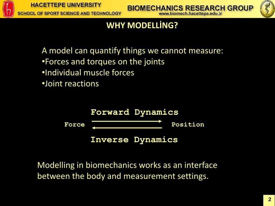
A model can quantify things we cannot measure: •Forces and torques on the joints •Individual muscle forces •Joint reactions
WHY MODELLİNG?
Force Position
Forward Dynamics
Inverse Dynamics
Modelling in biomechanics works as an interface between the body and measurement settings.
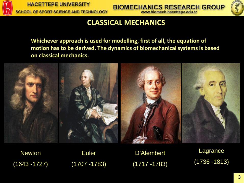
CLASSICAL MECHANICS
Whichever approach is used for modelling, first of all, the equation of motion has to be derived. The dynamics of biomechanical systems is based on classical mechanics.
3
Newton
(1643 -1727)
Euler
(1707 -1783)
D’Alembert
(1717 -1783)
Lagrance
(1736 -1813)
4
CLASSICAL MECHANICS
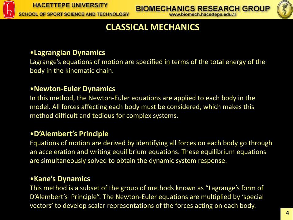
•Lagrangian Dynamics Lagrange’s equations of motion are specified in terms of the total energy of the body in the kinematic chain.
•Newton-Euler Dynamics In this method, the Newton-Euler equations are applied to each body in the model. All forces affecting each body must be considered, which makes this method difficult and tedious for complex systems.
•D’Alembert’s Principle Equations of motion are derived by identifying all forces on each body go through an acceleration and writing equilibrium equations. These equilibrium equations are simultaneously solved to obtain the dynamic system response.
•Kane’s Dynamics This method is a subset of the group of methods known as “Lagrange’s form of D’Alembert’s Principle”. The Newton-Euler equations are multiplied by ‘special vectors’ to develop scalar representations of the forces acting on each body.
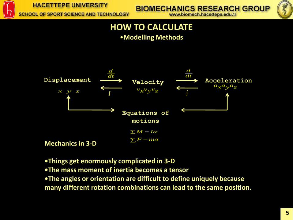
Mechanics in 3-D •Things get enormously complicated in 3-D •The mass moment of inertia becomes a tensor •The angles or orientation are difficult to define uniquely because many different rotation combinations can lead to the same position.
Displacement Velocity
Acceleration
Equations of
motions
zyx zvyvxv zayaxa
maF
IM
dtd
dtd
HOW TO CALCULATE •Modelling Methods
5
6
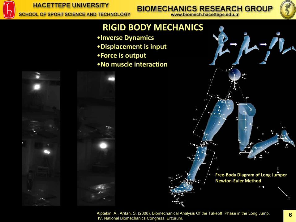
RIGID BODY MECHANICS •Inverse Dynamics •Displacement is input •Force is output •No muscle interaction
Free-Body Diagram of Long Jumper Newton-Euler Method
Alptekin, A., Arıtan, S. (2008). Biomechanical Analysis Of the Takeoff Phase in the Long Jump.
IV. National Biomechanics Congress. Erzurum.
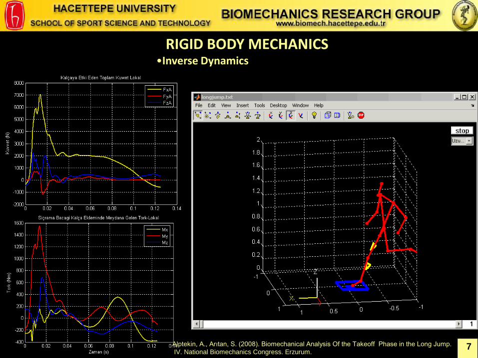
RIGID BODY MECHANICS •Inverse Dynamics
7 Alptekin, A., Arıtan, S. (2008). Biomechanical Analysis Of the Takeoff Phase in the Long Jump.
IV. National Biomechanics Congress. Erzurum.
8
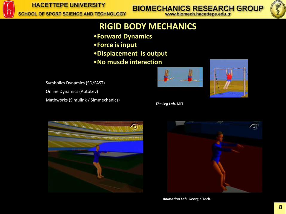
RIGID BODY MECHANICS •Forward Dynamics •Force is input •Displacement is output •No muscle interaction
Animation Lab. Georgia Tech.
The Leg Lab. MIT
Symbolics Dynamics (SD/FAST)
Online Dynamics (AutoLev)
Mathworks (Simulink / Simmechanics)
9
2
00
2
0000
2
0
00
0
00
2
1
)(2
1)(
2
2
0
0
0
0
tm
Ftvxx
ttm
Fttvxxdt
m
Fdtvdxx
dtdtm
Fvdxdt
m
Fv
dt
dxx
tm
Fvv
ttm
Fvvdt
m
Fdvv
dt
xdmdt
dvmmaF
t
t
t
x
x
t
t
v
v
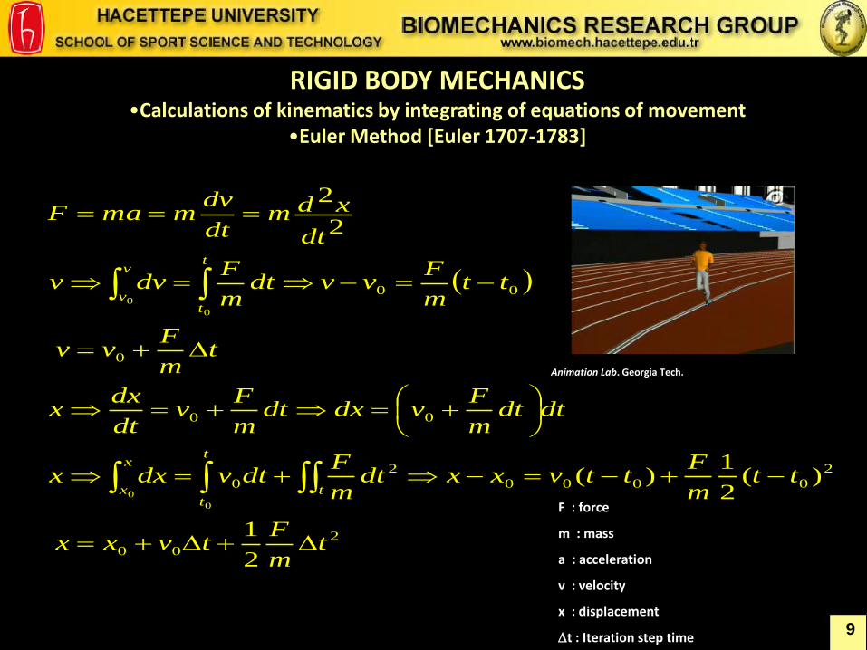
F : force
m : mass
a : acceleration
v : velocity
x : displacement
t : Iteration step time
Animation Lab. Georgia Tech.
RIGID BODY MECHANICS •Calculations of kinematics by integrating of equations of movement
•Euler Method [Euler 1707-1783]
10
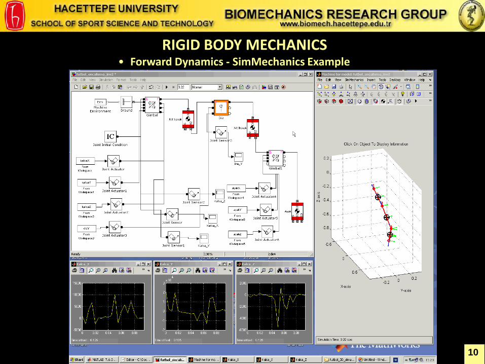
RIGID BODY MECHANICS • Forward Dynamics - SimMechanics Example
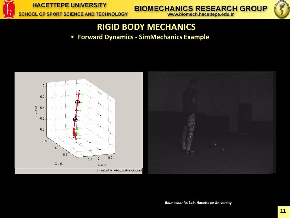
RIGID BODY MECHANICS • Forward Dynamics - SimMechanics Example
11
Biomechanics Lab. Hacettepe University
12
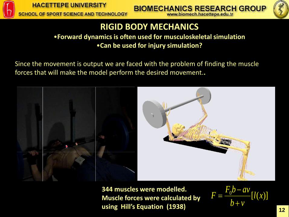
RIGID BODY MECHANICS •Forward dynamics is often used for musculoskeletal simulation
•Can be used for injury simulation?
Since the movement is output we are faced with the problem of finding the muscle forces that will make the model perform the desired movement..
344 muscles were modelled. Muscle forces were calculated by using Hill’s Equation (1938)
)]([0 xlvb
avbFF
13
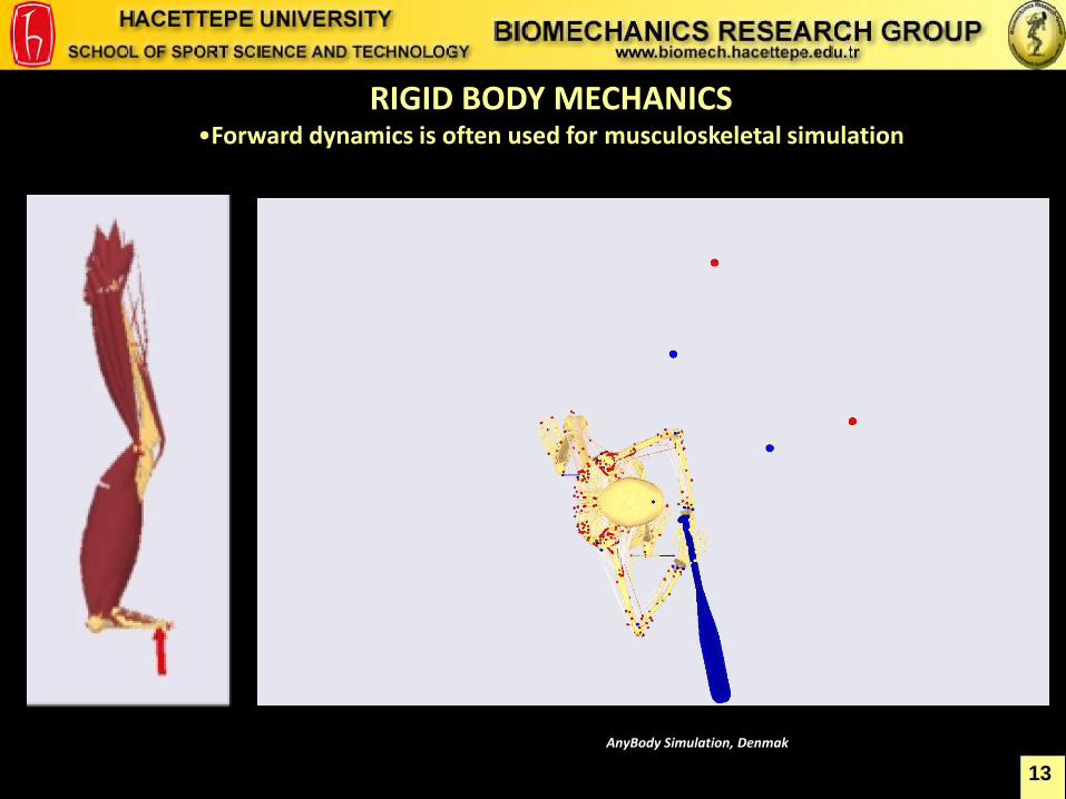
RIGID BODY MECHANICS •Forward dynamics is often used for musculoskeletal simulation
AnyBody Simulation, Denmak
14
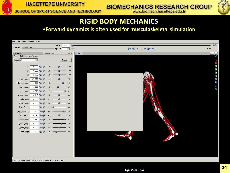
RIGID BODY MECHANICS •Forward dynamics is often used for musculoskeletal simulation
OpenSim, USA
15 OpenSim, USA
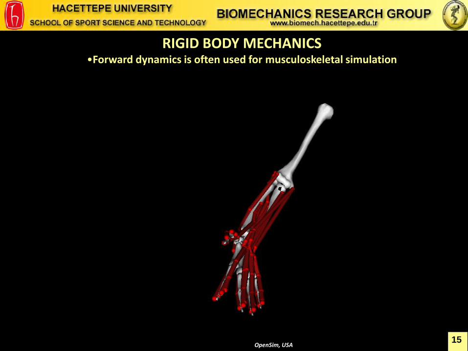
RIGID BODY MECHANICS •Forward dynamics is often used for musculoskeletal simulation
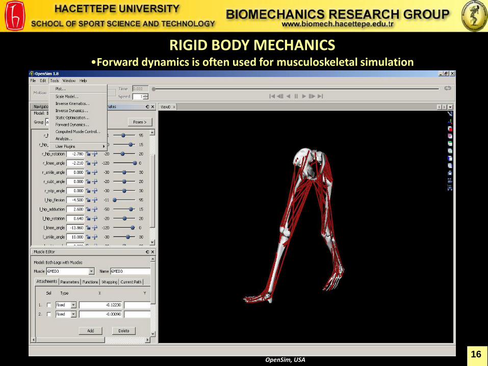
RIGID BODY MECHANICS •Forward dynamics is often used for musculoskeletal simulation
16 OpenSim, USA
17
RIGID BODY MECHANICS •EMG-Driven Models
• Basic idea. Record EMG from an experiment. • Process the EMG to a muscle activation signal. • Activate muscles in a computer model using the processed signal. • The muscle activation signal is initially forward-simulated to produce a muscle contraction history. • The muscle contractions create movement. • Adjust the process parameters to get the right movement out of the model.
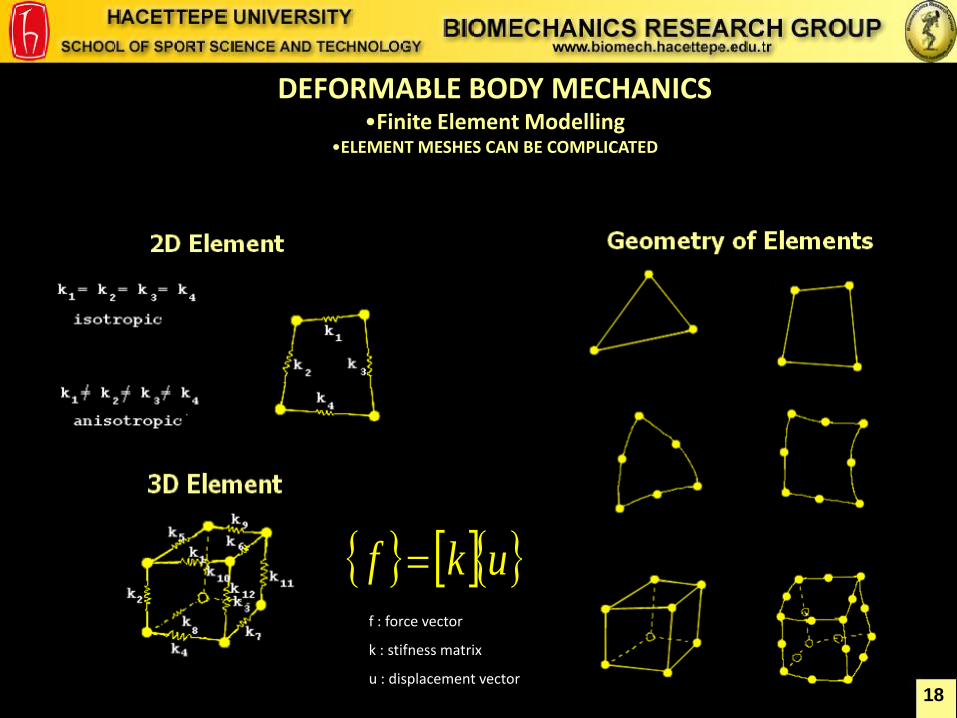
DEFORMABLE BODY MECHANICS •Finite Element Modelling
•ELEMENT MESHES CAN BE COMPLICATED
18
ukf f : force vector
k : stifness matrix
u : displacement vector
19
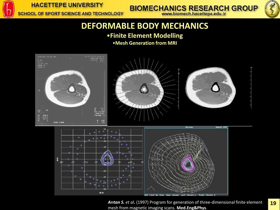
DEFORMABLE BODY MECHANICS •Finite Element Modelling
•Mesh Generation from MRI
Arıtan S. et al. (1997) Program for generation of three-dimensional finite element mesh from magnetic imaging scans. Med.Eng&Phys.
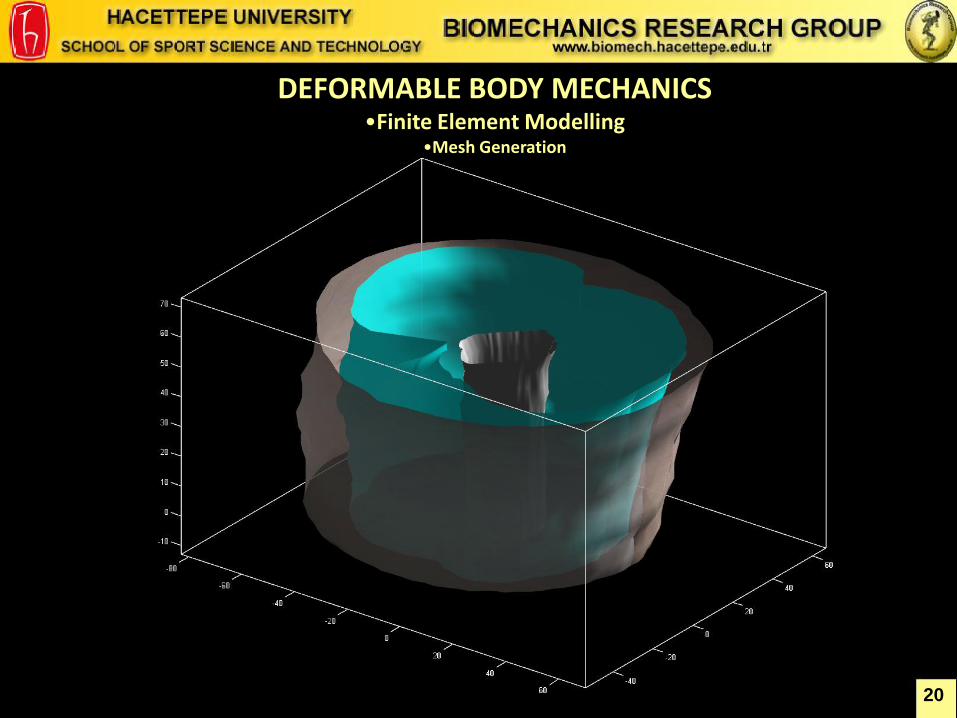
DEFORMABLE BODY MECHANICS •Finite Element Modelling
•Mesh Generation
20
21
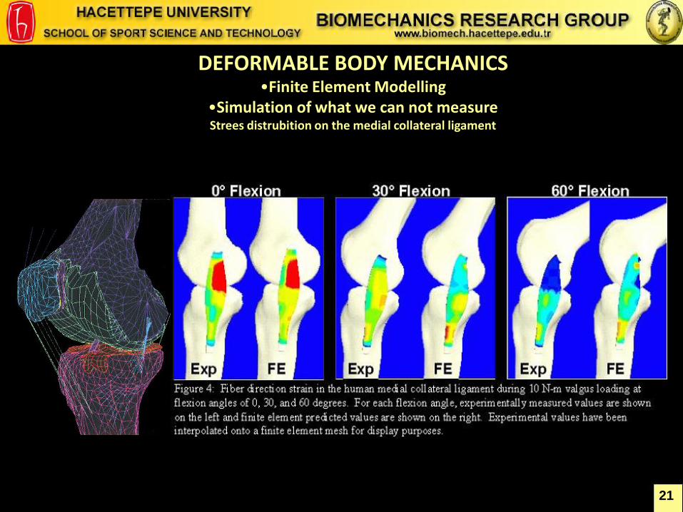
DEFORMABLE BODY MECHANICS •Finite Element Modelling
•Simulation of what we can not measure Strees distrubition on the medial collateral ligament
Asai T. University of Yamagata
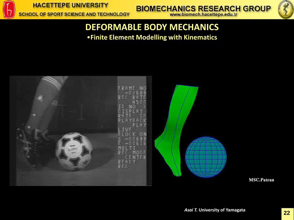
DEFORMABLE BODY MECHANICS •Finite Element Modelling with Kinematics
22
23
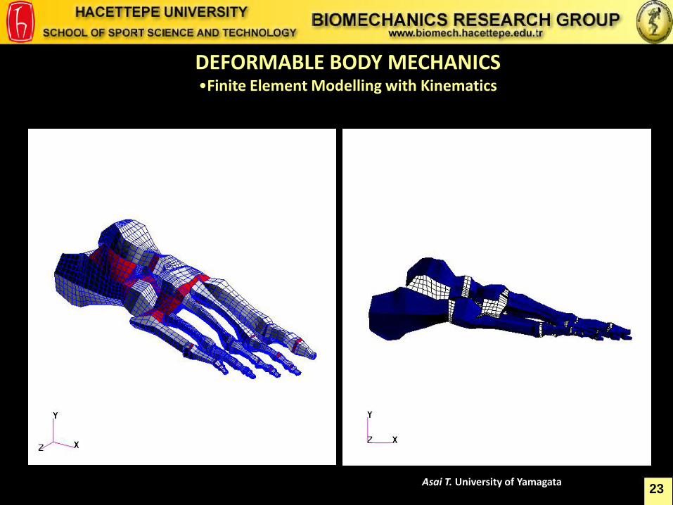
DEFORMABLE BODY MECHANICS •Finite Element Modelling with Kinematics
Asai T. University of Yamagata
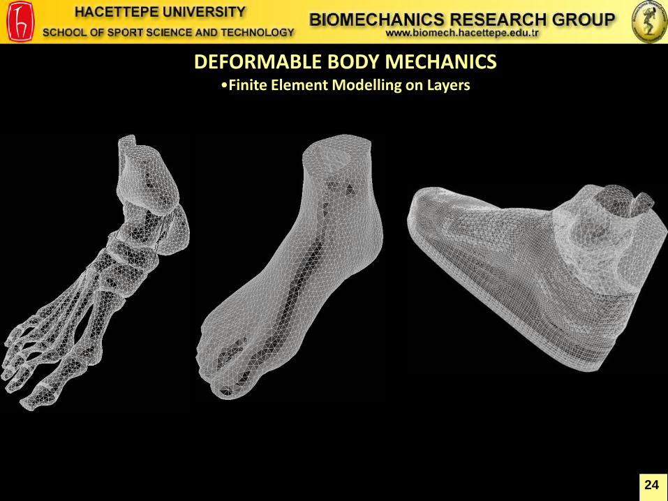
DEFORMABLE BODY MECHANICS •Finite Element Modelling on Layers
24
25
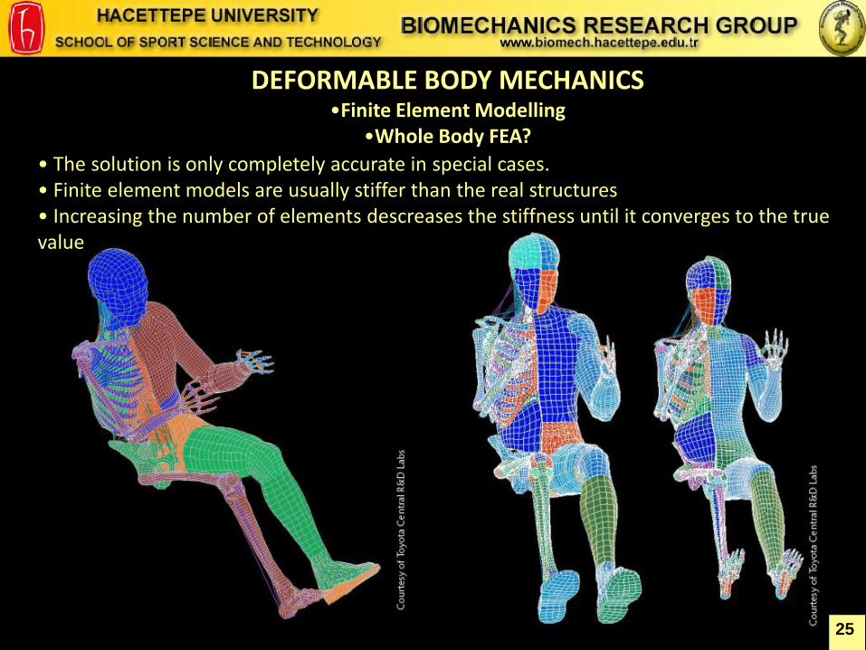
DEFORMABLE BODY MECHANICS •Finite Element Modelling
•Whole Body FEA?
• The solution is only completely accurate in special cases. • Finite element models are usually stiffer than the real structures • Increasing the number of elements descreases the stiffness until it converges to the true value
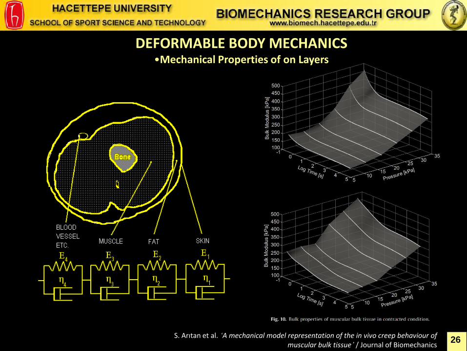
S. Arıtan et al. ‘A mechanical model representation of the in vivo creep behaviour of muscular bulk tissue’ / Journal of Biomechanics
DEFORMABLE BODY MECHANICS •Mechanical Properties of on Layers
26
27
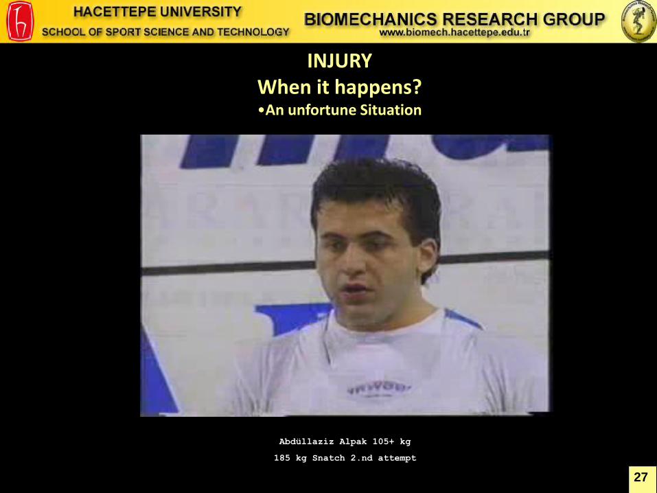
INJURY When it happens? •An unfortune Situation
Abdüllaziz Alpak 105+ kg
185 kg Snatch 2.nd attempt
28
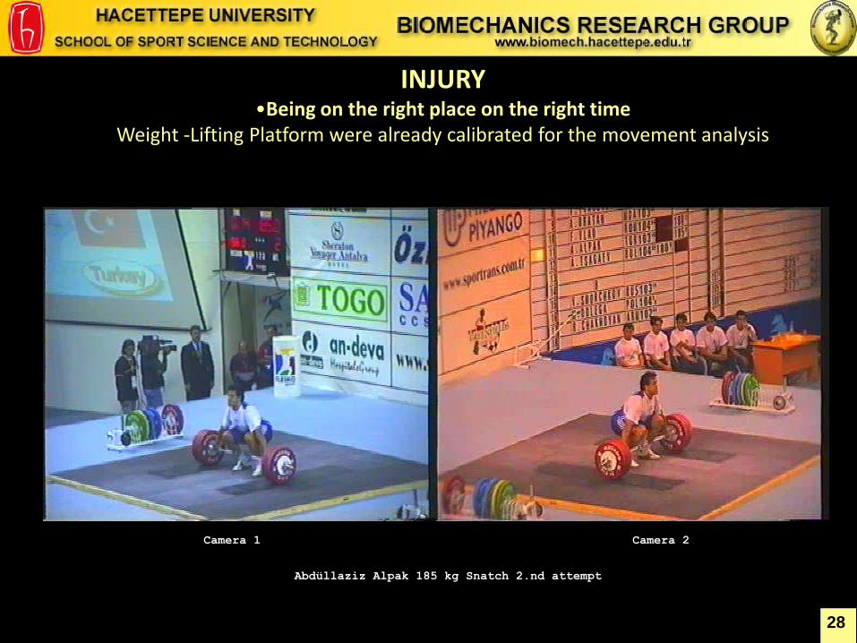
INJURY •Being on the right place on the right time
Weight -Lifting Platform were already calibrated for the movement analysis
Abdüllaziz Alpak 185 kg Snatch 2.nd attempt
Camera 2 Camera 1
29
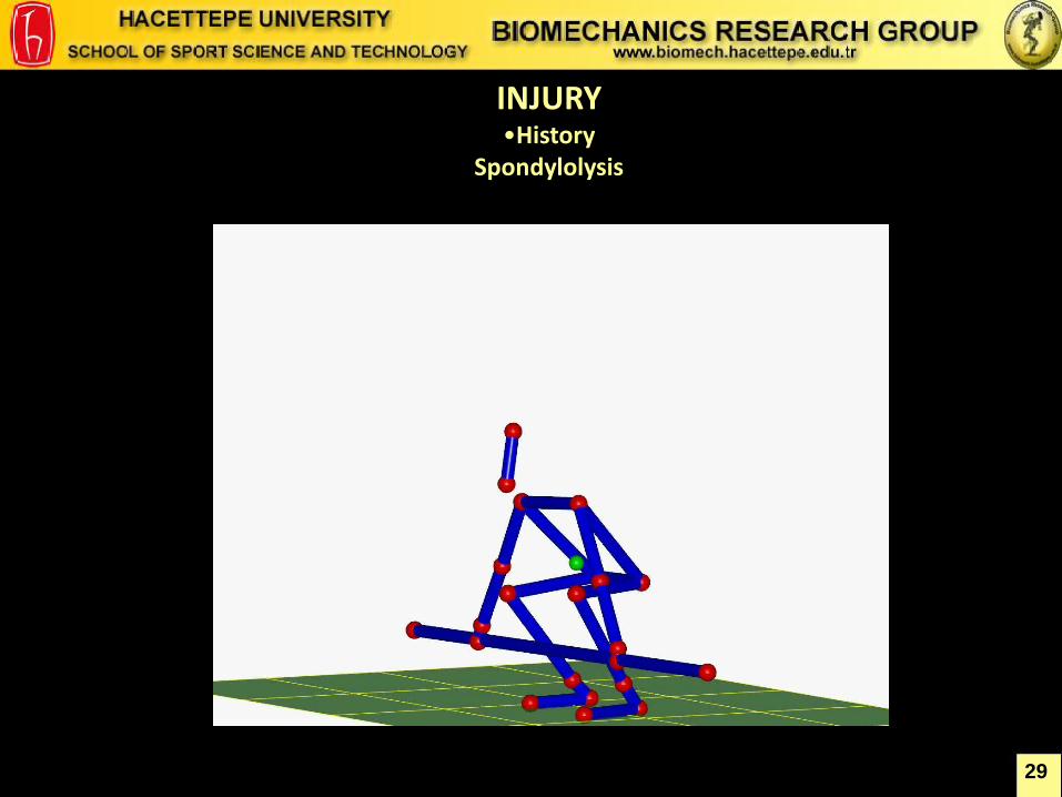
INJURY •History
Spondylolysis
30
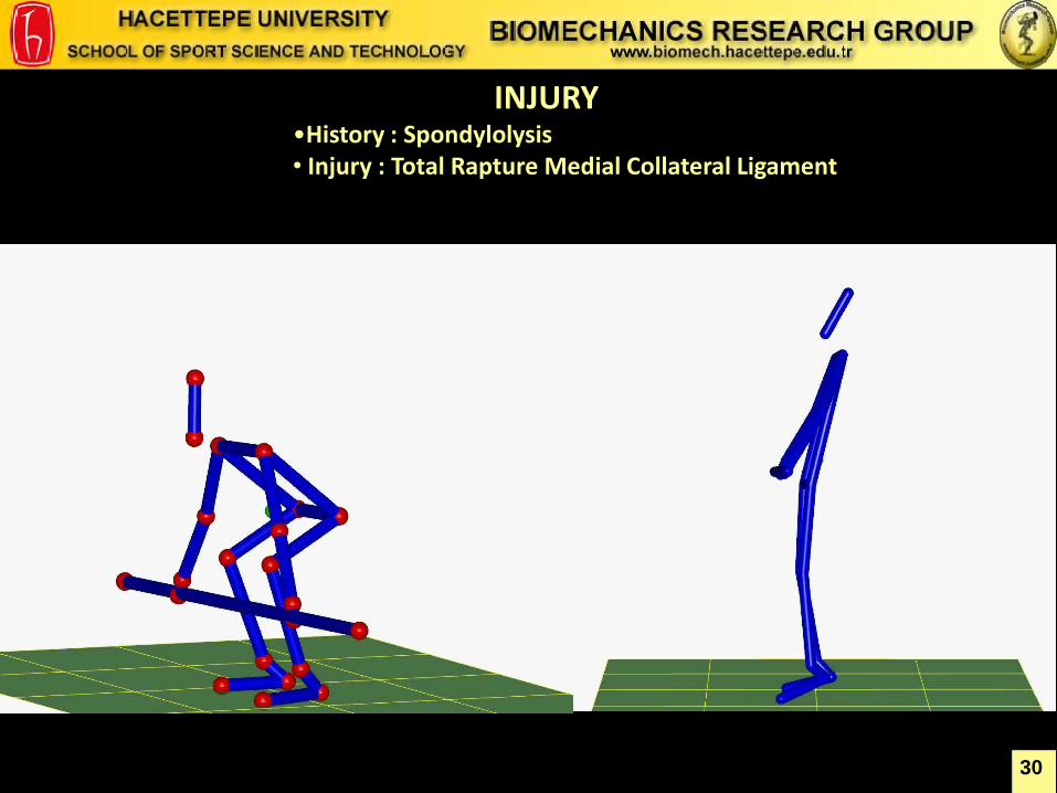
INJURY •History : Spondylolysis • Injury : Total Rapture Medial Collateral Ligament
31
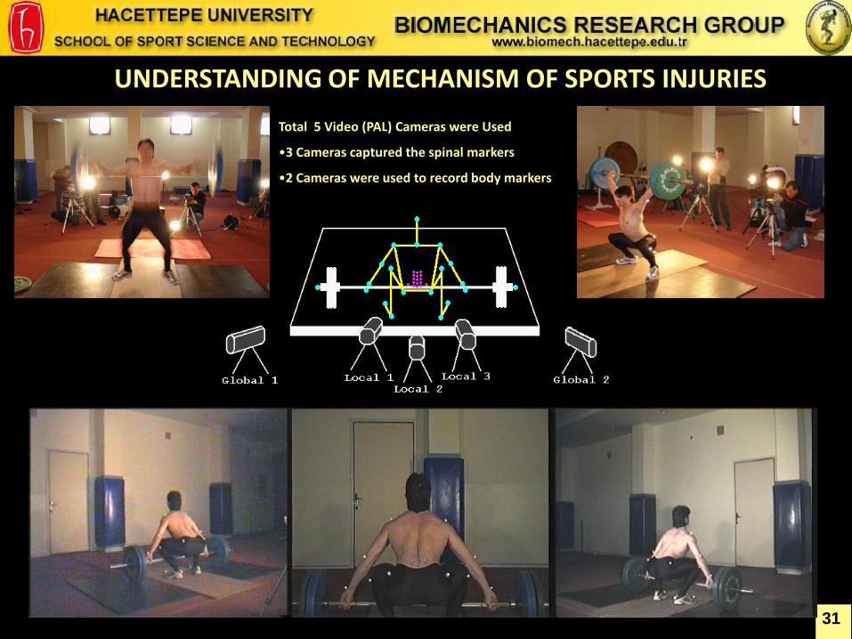
UNDERSTANDING OF MECHANISM OF SPORTS INJURIES
Total 5 Video (PAL) Cameras were Used
•3 Cameras captured the spinal markers
•2 Cameras were used to record body markers
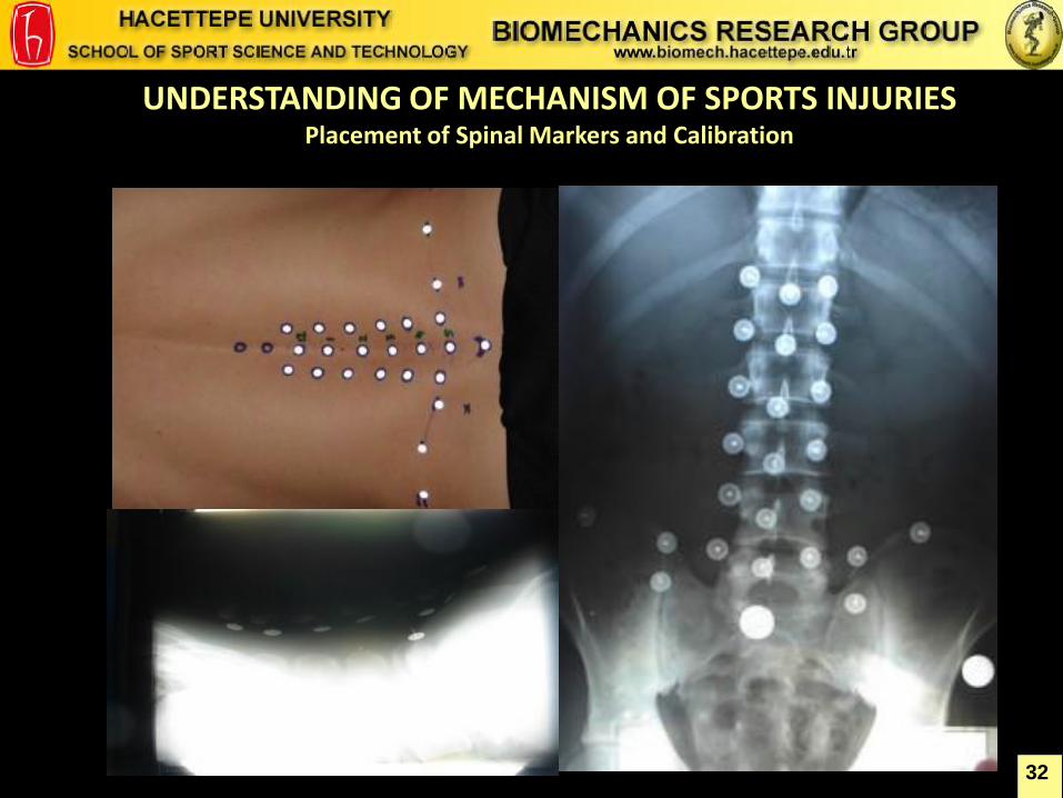
UNDERSTANDING OF MECHANISM OF SPORTS INJURIES Placement of Spinal Markers and Calibration
32
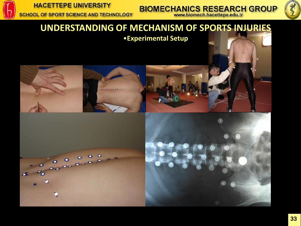
UNDERSTANDING OF MECHANISM OF SPORTS INJURIES •Experimental Setup
33
34
UNDERSTANDING OF MECHANISM OF SPORTS INJURIES Spine and Body Movement An Inverse Dynamics Study
Torque on L5, Calculated by D’Alembert Principle
35
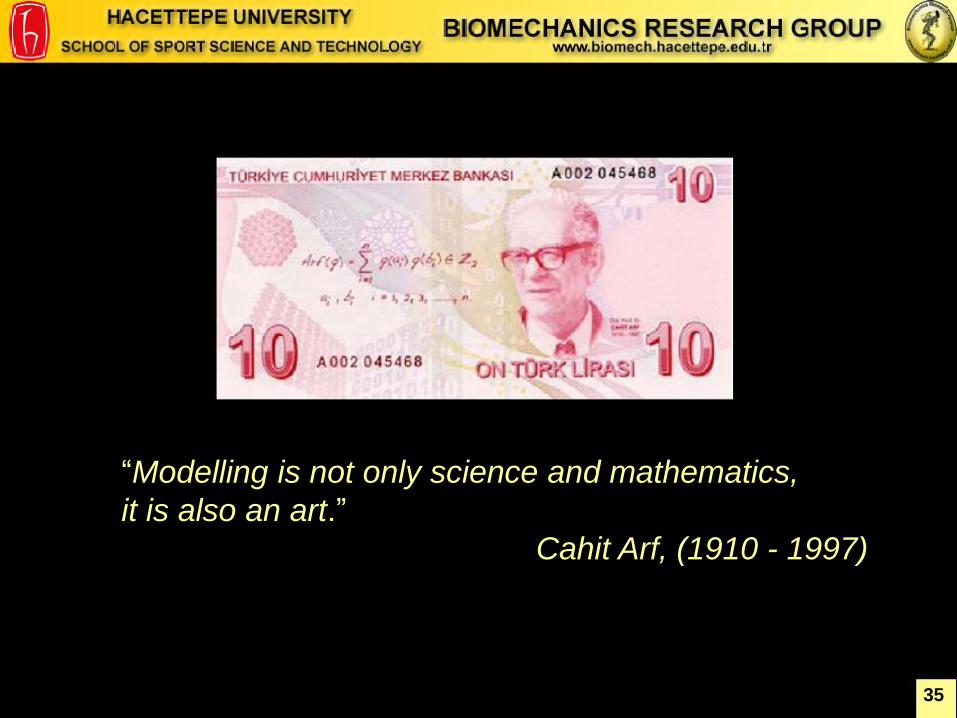
“Modelling is not only science and mathematics,
it is also an art.”
Cahit Arf, (1910 - 1997)

36
Thank you for your Attention
School of Sport Science and
Technology www.sbt.hacettepe.edu.tr
Hacettepe University
Beytepe Campus www.hacettepe.edu.tr