big data with cisco ucs and emc isilon: building a 60 node
TRANSCRIPT
Big Data with Cisco UCS and EMC Isilon: Building a 60 Node Hadoop Cluster
Last Updated: March 22, 2015
Building Architectures to Solve Business Problems

Cisco Validated Design2
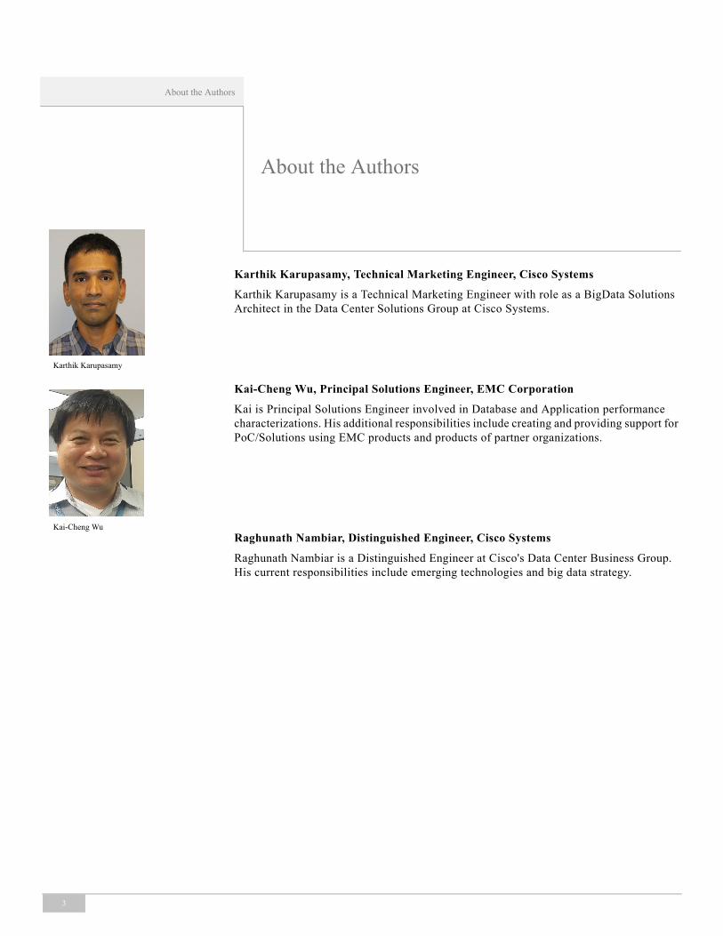
About the Authors
3
Karthik Karupasamy
Kai-Cheng Wu
About the Authors
Karthik Karupasamy, Technical Marketing Engineer, Cisco Systems
Karthik Karupasamy is a Technical Marketing Engineer with role as a BigData Solutions Architect in the Data Center Solutions Group at Cisco Systems.
Kai-Cheng Wu, Principal Solutions Engineer, EMC Corporation
Kai is Principal Solutions Engineer involved in Database and Application performance characterizations. His additional responsibilities include creating and providing support for PoC/Solutions using EMC products and products of partner organizations.
Raghunath Nambiar, Distinguished Engineer, Cisco Systems
Raghunath Nambiar is a Distinguished Engineer at Cisco's Data Center Business Group. His current responsibilities include emerging technologies and big data strategy.
About Cisco Validated Design (CVD) Program
The CVD program consists of systems and solutions designed, tested, and documented to facilitate faster, more reliable, and more predictable customer deployments. For more information visit: http://www.cisco.com/go/designzone.
ALL DESIGNS, SPECIFICATIONS, STATEMENTS, INFORMATION, AND RECOMMENDATIONS (COLLECTIVELY, "DESIGNS") IN THIS MANUAL ARE PRESENTED "AS IS," WITH ALL FAULTS. CISCO AND ITS SUPPLIERS DISCLAIM ALL WARRANTIES, INCLUDING, WITHOUT LIMITATION, THE WARRANTY OF MERCHANTABILITY, FITNESS FOR A PARTICULAR PURPOSE AND NONINFRINGEMENT OR ARISING FROM A COURSE OF DEALING, USAGE, OR TRADE PRACTICE. IN NO EVENT SHALL CISCO OR ITS SUPPLIERS BE LIABLE FOR ANY INDIRECT, SPECIAL, CONSEQUENTIAL, OR INCIDENTAL DAMAGES, INCLUDING, WITHOUT LIMITATION, LOST PROFITS OR LOSS OR DAMAGE TO DATA ARISING OUT OF THE USE OR INABILITY TO USE THE DESIGNS, EVEN IF CISCO OR ITS SUPPLIERS HAVE BEEN ADVISED OF THE POSSIBILITY OF SUCH DAMAGES.
THE DESIGNS ARE SUBJECT TO CHANGE WITHOUT NOTICE. USERS ARE SOLELY RESPONSIBLE FOR THEIR APPLICATION OF THE DESIGNS. THE DESIGNS DO NOT CONSTITUTE THE TECHNICAL OR OTHER PROFESSIONAL ADVICE OF CISCO, ITS SUPPLIERS OR PARTNERS. USERS SHOULD CONSULT THEIR OWN TECHNICAL ADVISORS BEFORE IMPLEMENTING THE DESIGNS. RESULTS MAY VARY DEPENDING ON FACTORS NOT TESTED BY CISCO.
The Cisco implementation of TCP header compression is an adaptation of a program developed by the University of California, Berkeley (UCB) as part of UCB’s public domain version of the UNIX operating system. All rights reserved. Copyright © 1981, Regents of the University of California.
Cisco and the Cisco logo are trademarks or registered trademarks of Cisco and/or its affiliates in the U.S. and other countries. To view a list of Cisco trademarks, go to this URL: http://www.cisco.com/go/trademarks. Third-party trademarks mentioned are the property of their respective owners. The use of the word partner does not imply a partnership relationship between Cisco and any other company. (1110R).
Any Internet Protocol (IP) addresses and phone numbers used in this document are not intended to be actual addresses and phone numbers. Any examples, command display output, network topology diagrams, and other figures included in the document are shown for illustrative purposes only. Any use of actual IP addresses or phone numbers in illustrative content is unintentional and coincidental.
Big Data with Cisco UCS and EMC Isilon: Building a 60 Node Hadoop Cluster
© 2015 Cisco Systems, Inc. All rights reserved.
4About Cisco Validated Design (CVD) Program
AcknowledgmentThe authors acknowledge Claudio Fahey (EMC), Bo Dong (VMware), Darren Marinko (Cisco), David Nguyen (Cisco), Karthik Kulkarni (Cisco), Hai Yee (Cisco), Manankumar Trivedi (Cisco), Sindhu Sudhir (Cisco) for their contributions in developing this document.
Big Data with Cisco UCS and EMC Isilon: Building a 60 Node Hadoop Cluster
IntroductionHadoop has evolved into a significant modern day data platform for processing and extracting valuable insights from massive volume of variety of data gathered by the mainstream enterprises. It offers the fastest path for businesses to take advantages of the hidden value in big data technology while maximizing the benefits of their existing database investments.
In this Cisco Validated Design (CVD), we address the above critical challenge faced in scaling up, scaling down and scaling out the Hadoop clusters to meet the customers’ ever-changing requirements by implementing Virtualized Hadoop solution. The design presented in this document offers a modular, scalable and integrated architecture that can be easily deployed, minimizing the downtime. The Virtualized Hadoop solution is implemented using Cisco UCS, EMC® Isilon® and VMware vSphere® Big Data Extension (BDE) combination. In this solution we have used Cloudera's CDH5 enterprise distribution.
AudienceThis document describes the architecture, deployment procedures of building a Virtualized Hadoop solution using Cisco UCS B200 M3 blade servers and EMC Isilon scale-out NAS and vSphere Big Data Extensions. The intended audience include, but not limited to, sales engineers, field consultants, professional services, IT managers, partner engineering and customers who want to deploy a Virtualized Hadoop solution in their data centers.
The Building Blocks
Figure 1 illustrates the building blocks of this Virtualized Hadoop solution. The hardware components consist of Cisco UCS B-Series blade servers, Cisco UCS Fabric Interconnects and EMC Isilon S-Series nodes along with the intra-cluster communication infrastructure (backplane).
Corporate Headquarters:
Copyright © 2014 Cisco Systems, Inc. All rights reserved.
Cisco Systems, Inc., 170 West Tasman Drive, San Jose, CA 95134-1706 USA
Audience
Cisco Unified Computing System provides the compute, network, and storage access components in this solution. EMC Isilon scale-out NAS runs NameNode and DataNode services providing direct HDFS access to the compute nodes. The combination of EMC Isilon and Cisco UCS provides industry-leading platform for Hadoop based applications. This Hadoop solution uses the Cloudera Enterprise (CDH) which is a 100% open-source distribution of Apache Hadoop. The Hadoop Cluster deployment and management are performed by the VMware’s vSphere Big Data Extensions (BDE).
Figure 1 Building Blocks of Cisco Unified Computing System
We have VMware’s vSphere Big Data Extensions (version 2.1), vSphere ESXi 5.5, vCenter-Server Appliance 5.5 and CDH 5.1.3 on RedHat Enterprise Linux (RHEL 6.4) as software components for creating this Virtualized Hadoop solution.
Cisco UCS Compute and Network Components
The Cisco UCS provides a highly scalable architecture designed to meet a variety of scale-out application demands with seamless data integration and management integration capabilities built using the following components:
• Cisco UCS 6200 Series Fabric Interconnects—This provide high-bandwidth, low-latency connectivity for servers, with integrated, unified management provided for all connected devices by Cisco UCS Manager. Deployed in redundant pairs, Cisco fabric interconnects offer the full active-active redundancy, performance, and exceptional scalability needed to support the large number of nodes that are typical in clusters serving big data applications. Cisco UCS Manger enables rapid and consistent server configuration using service profiles, automating ongoing system maintenance activities such as firmware updates across the entire cluster as a single operation. Cisco UCS Manager also offers advanced monitoring with options to raise alarms and send notifications about the health of the entire cluster.
• Cisco UCS 2200 Series Fabric Extender IO-Modules—This extends the network into each chassis, acting as remote line cards for fabric interconnects and providing highly scalable and extremely cost-effective connectivity for a large number of servers.
• Cisco UCS B-Series Blade Servers—Cisco UCS B200 M3 Blade Servers are 2-socket servers based on Intel Xeon E-2600 v2 series processors and supporting up to 768 GB of main memory and 2 Small Form Factor (SFF) SAS/SATA/SSD disks, along with VIC 1240 mLOM (modular LAN on Motherboard) delivering 4 X 10Gbps bandwidth per blade server.
7Big Data with Cisco UCS and EMC Isilon: Building a 60 Node Hadoop Cluster
Audience
• Cisco UCS Virtual Interface Cards (VIC)—This is unique to Cisco, Cisco UCS Virtual Interface Cards incorporate next-generation converged network adapter (CNA) technology from Cisco, and offer 4 X 10-Gbps ports designed for use with Cisco UCS B-Series Servers. Optimized for Virtualized networking, these cards deliver high performance and bandwidth utilization and support up to 256 virtual devices.
• Cisco UCS Manager—The Cisco UCS Manager resides within the Cisco UCS 6200 Series Fabric Interconnects. It makes the system self-aware and self-integrating, managing all of the system components as a single logical entity. Cisco UCS Manager can be accessed through an intuitive graphical user interface (GUI), a command-line interface (CLI), or an XML application-programming interface (API). Cisco UCS Manager uses service profiles to define the personality, configuration, and connectivity of all resources within Cisco UCS, radically simplifying provisioning of resources so that the process takes minutes instead of days. This simplification allows IT departments to shift their focus from constant maintenance to strategic business initiatives.
Scale-Out Architecture With EMC Isilon
The EMC Isilon scale-out network-attached storage (NAS) cluster provides direct access to Hadoop File System (HDFS) for the big data applications.
• Isilon scale-out NAS is a fully distributed system that consists of nodes of modular hardware arranged in a cluster.
• The distributed Isilon OneFS operating system combines the memory, I/O, CPUs, and disks of the nodes into a cohesive storage unit to present a global namespace as a single file system.
• The nodes work together as peers in a shared-nothing hardware architecture with no single point of failure.
• Every node adds capacity, performance, and resiliency to the storage cluster and each node acts as a Hadoop namenode and datanode.
• The namenode daemon is a distributed process that runs on all the nodes of the Isilon Cluster. A compute client can connect to any node in the cluster to access namenode services.
• As nodes are added, the file system expands dynamically and redistributes data, eliminating the work of partitioning disks and creating volumes.
8Big Data with Cisco UCS and EMC Isilon: Building a 60 Node Hadoop Cluster
Solution Overview
Figure 2 Isilon Scale-Out NAS Architecture
Solution OverviewThis Cisco Validated Design (CVD) describes the process of building a Virtualized Hadoop solution using Cisco UCS B-Series servers, a S200 EMC Isilon cluster and VMware vCenter Server along with its Big Data Extensions.
The infrastructure consists of the following components:
• Two Cisco UCS 6296UP Fabric Interconnects
• Two Cisco UCS 5108 Chassis each with two Cisco UCS 2208 Fabric Extenders (IO Modules)
• 16 Cisco UCS B200 M3 Half-Width blade servers (8 per chassis) with VIC 1240
• 8 EMC Isilon S200 nodes along with 2 Infiniband switches
• One Cisco R42610 standard rack
• Two Vertical Power distribution units (PDUs) (Country Specific)
Cisco Unified Computing System (UCS)
Cisco UCS a set of pre-integrated data center components that comprises blade servers, adapters, fabric-interconnects, and fabric-extenders that are integrated under a common embedded management system. This approach results in far fewer system components and much better manageability, operational efficiencies, and flexibility than comparable data center platforms.
The Cisco UCS is designed from the ground up to be programmable and self-integrating. A server’s entire hardware stack, ranging from server firmware and settings to network profiles, is configured through model-based management. With Cisco virtual interface cards, even the number and type of I/O interfaces is programmed dynamically, making every server ready to power any workload at any time.
9Big Data with Cisco UCS and EMC Isilon: Building a 60 Node Hadoop Cluster
Solution Overview
With model-based management, administrators manipulate a model of a desired system configuration, associate a model’s service profile with hardware resources and the system configures itself to match the model. This automation speeds provisioning and workload migration with accurate and rapid scalability. The result is increased IT staff productivity, improved compliance, and reduced risk of failures due to inconsistent configurations.
Cisco Fabric Extender technology reduces the number of system components to purchase, configure, manage, and maintain by condensing three network layers into one. It eliminates both blade server and hypervisor-based switches by connecting fabric interconnect ports directly to individual blade servers and virtual machines. Virtual networks are now managed exactly as physical networks are, but with massive scalability. This represents a radical simplification over traditional systems, reducing capital and operating costs while increasing business agility, simplifying and speeding deployment, and improving performance.
Cisco Fabric Interconnect
Cisco UCS Fabric Interconnects creates a unified network fabric throughout the Cisco UCS. They provide uniform access to both networks and storage, eliminating the barriers to deploying a fully virtualized environment based on a flexible, programmable pool of resources.
Cisco Fabric Interconnects comprise a family of line-rate, low-latency, lossless 10-GE, Cisco Data Center Ethernet, and FCoE interconnect switches. Based on the same switching technology as the Cisco Nexus 5000 Series, Cisco UCS 6000 Series Fabric Interconnects provide the additional features and management capabilities that make them the central nervous system of Cisco UCS.
The Cisco UCS Manager software runs inside the Cisco UCS Fabric Interconnects. The Cisco UCS 6000 Series Fabric Interconnects expand the UCS networking portfolio and offer higher capacity, higher port density, and lower power consumption. These interconnects provide the management and communication backbone for the Cisco UCS B-Series Blades and Cisco UCS Blade Server Chassis.
All chassis and all blades that are attached to the Fabric Interconnects are part of a single, highly available management domain. By supporting unified fabric, the Cisco UCS 6200 Series provides the flexibility to support LAN and SAN connectivity for all blades within its domain right at configuration time. Typically deployed in redundant pairs, the Cisco UCS Fabric Interconnect provides uniform access to both networks and storage, facilitating a fully virtualized environment.
The Cisco UCS Fabric Interconnect family is currently comprised of the Cisco 6100 Series and Cisco 6200 Series of Fabric Interconnects.
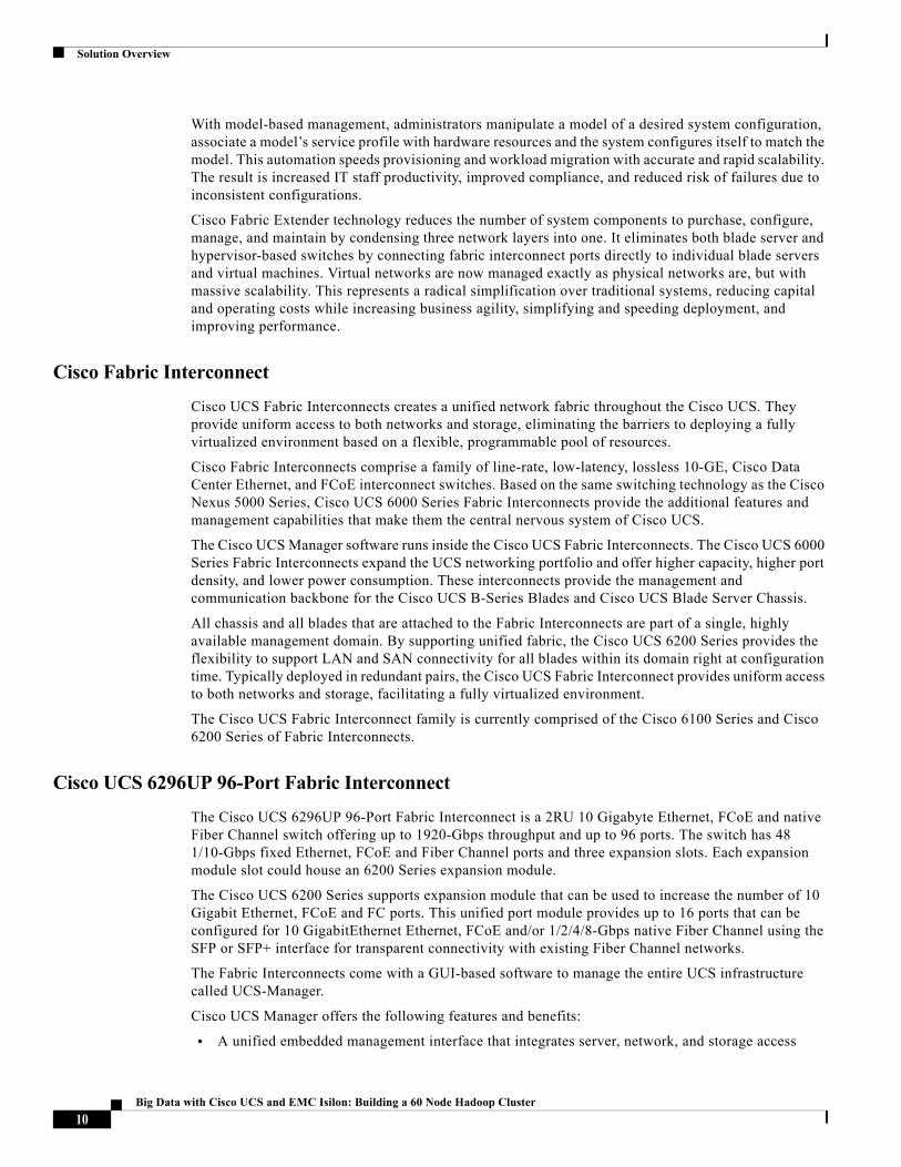
Cisco UCS 6296UP 96-Port Fabric Interconnect
The Cisco UCS 6296UP 96-Port Fabric Interconnect is a 2RU 10 Gigabyte Ethernet, FCoE and native Fiber Channel switch offering up to 1920-Gbps throughput and up to 96 ports. The switch has 48 1/10-Gbps fixed Ethernet, FCoE and Fiber Channel ports and three expansion slots. Each expansion module slot could house an 6200 Series expansion module.
The Cisco UCS 6200 Series supports expansion module that can be used to increase the number of 10 Gigabit Ethernet, FCoE and FC ports. This unified port module provides up to 16 ports that can be configured for 10 GigabitEthernet Ethernet, FCoE and/or 1/2/4/8-Gbps native Fiber Channel using the SFP or SFP+ interface for transparent connectivity with existing Fiber Channel networks.
The Fabric Interconnects come with a GUI-based software to manage the entire UCS infrastructure called UCS-Manager.
Cisco UCS Manager offers the following features and benefits:
• A unified embedded management interface that integrates server, network, and storage access
10Big Data with Cisco UCS and EMC Isilon: Building a 60 Node Hadoop Cluster
Solution Overview
• Policy and model-based management, with service profiles, that improves agility and reduces risk
• Auto-discovery to detect, inventory, manage, and provision system components that are added or changed
• A comprehensive open XML API, which facilitates integration with third-party systems management tools
• Role-based administration that builds on existing skills and supports collaboration across disciplines
Figure 3 Cisco UCS 6296UP Fabric Interconnect
Cisco UCS Chassis
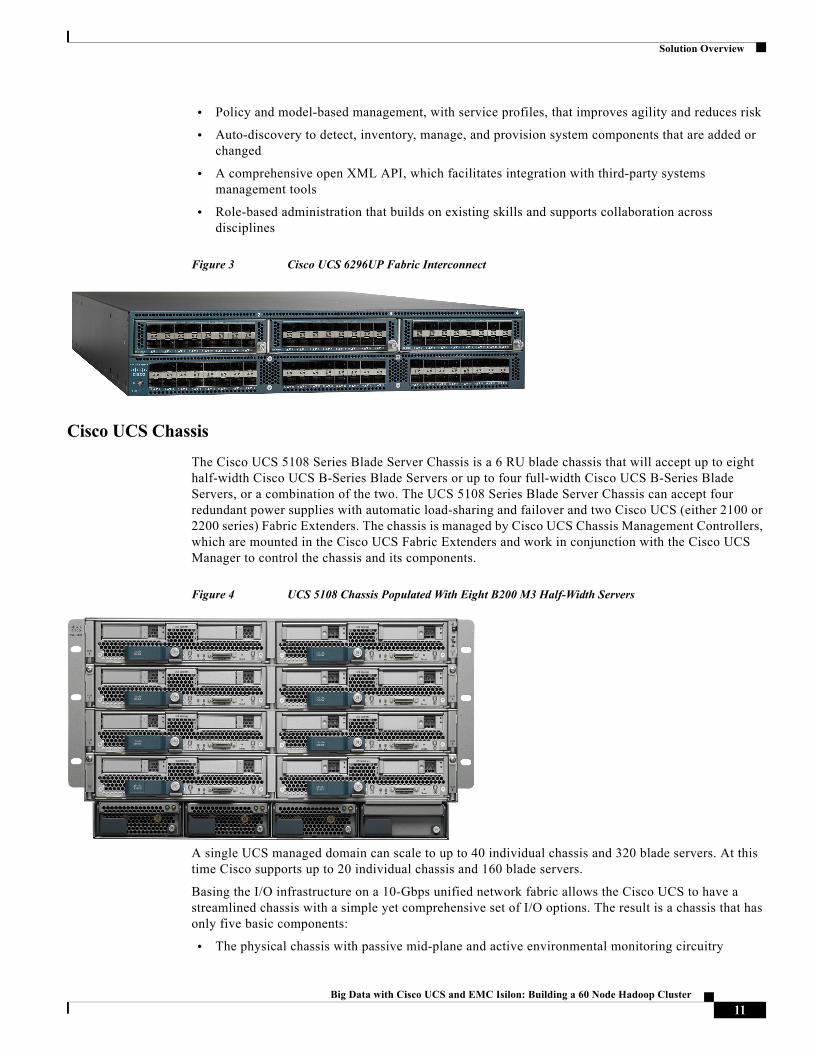
The Cisco UCS 5108 Series Blade Server Chassis is a 6 RU blade chassis that will accept up to eight half-width Cisco UCS B-Series Blade Servers or up to four full-width Cisco UCS B-Series Blade Servers, or a combination of the two. The UCS 5108 Series Blade Server Chassis can accept four redundant power supplies with automatic load-sharing and failover and two Cisco UCS (either 2100 or 2200 series) Fabric Extenders. The chassis is managed by Cisco UCS Chassis Management Controllers, which are mounted in the Cisco UCS Fabric Extenders and work in conjunction with the Cisco UCS Manager to control the chassis and its components.
Figure 4 UCS 5108 Chassis Populated With Eight B200 M3 Half-Width Servers
A single UCS managed domain can scale to up to 40 individual chassis and 320 blade servers. At this time Cisco supports up to 20 individual chassis and 160 blade servers.
Basing the I/O infrastructure on a 10-Gbps unified network fabric allows the Cisco UCS to have a streamlined chassis with a simple yet comprehensive set of I/O options. The result is a chassis that has only five basic components:
• The physical chassis with passive mid-plane and active environmental monitoring circuitry
11Big Data with Cisco UCS and EMC Isilon: Building a 60 Node Hadoop Cluster
Solution Overview
• Four power supply bays with power entry in the rear, and hot-swappable power supply units accessible from the front panel
• Eight hot-swappable fan trays, each with two fans
• Two fabric extender slots accessible from the back panel
• Eight blade server slots accessible from the front panel
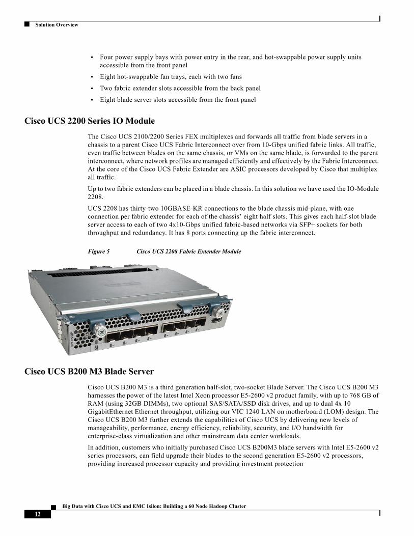
Cisco UCS 2200 Series IO Module
The Cisco UCS 2100/2200 Series FEX multiplexes and forwards all traffic from blade servers in a chassis to a parent Cisco UCS Fabric Interconnect over from 10-Gbps unified fabric links. All traffic, even traffic between blades on the same chassis, or VMs on the same blade, is forwarded to the parent interconnect, where network profiles are managed efficiently and effectively by the Fabric Interconnect. At the core of the Cisco UCS Fabric Extender are ASIC processors developed by Cisco that multiplex all traffic.
Up to two fabric extenders can be placed in a blade chassis. In this solution we have used the IO-Module 2208.
UCS 2208 has thirty-two 10GBASE-KR connections to the blade chassis mid-plane, with one connection per fabric extender for each of the chassis’ eight half slots. This gives each half-slot blade server access to each of two 4x10-Gbps unified fabric-based networks via SFP+ sockets for both throughput and redundancy. It has 8 ports connecting up the fabric interconnect.
Figure 5 Cisco UCS 2208 Fabric Extender Module
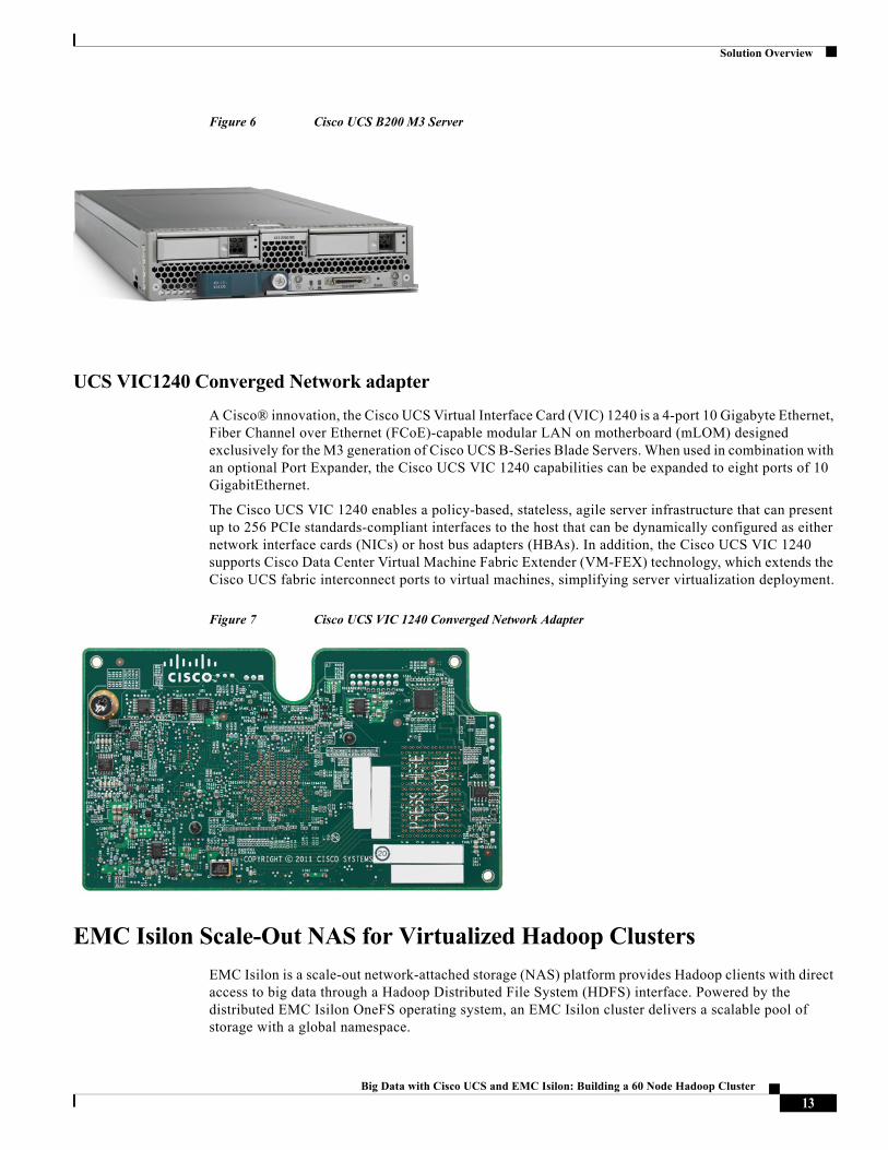
Cisco UCS B200 M3 Blade Server
Cisco UCS B200 M3 is a third generation half-slot, two-socket Blade Server. The Cisco UCS B200 M3 harnesses the power of the latest Intel Xeon processor E5-2600 v2 product family, with up to 768 GB of RAM (using 32GB DIMMs), two optional SAS/SATA/SSD disk drives, and up to dual 4x 10 GigabitEthernet Ethernet throughput, utilizing our VIC 1240 LAN on motherboard (LOM) design. The Cisco UCS B200 M3 further extends the capabilities of Cisco UCS by delivering new levels of manageability, performance, energy efficiency, reliability, security, and I/O bandwidth for enterprise-class virtualization and other mainstream data center workloads.
In addition, customers who initially purchased Cisco UCS B200M3 blade servers with Intel E5-2600 v2 series processors, can field upgrade their blades to the second generation E5-2600 v2 processors, providing increased processor capacity and providing investment protection
12Big Data with Cisco UCS and EMC Isilon: Building a 60 Node Hadoop Cluster
Solution Overview
Figure 6 Cisco UCS B200 M3 Server
UCS VIC1240 Converged Network adapter
A Cisco® innovation, the Cisco UCS Virtual Interface Card (VIC) 1240 is a 4-port 10 Gigabyte Ethernet, Fiber Channel over Ethernet (FCoE)-capable modular LAN on motherboard (mLOM) designed exclusively for the M3 generation of Cisco UCS B-Series Blade Servers. When used in combination with an optional Port Expander, the Cisco UCS VIC 1240 capabilities can be expanded to eight ports of 10 GigabitEthernet.
The Cisco UCS VIC 1240 enables a policy-based, stateless, agile server infrastructure that can present up to 256 PCIe standards-compliant interfaces to the host that can be dynamically configured as either network interface cards (NICs) or host bus adapters (HBAs). In addition, the Cisco UCS VIC 1240 supports Cisco Data Center Virtual Machine Fabric Extender (VM-FEX) technology, which extends the Cisco UCS fabric interconnect ports to virtual machines, simplifying server virtualization deployment.
Figure 7 Cisco UCS VIC 1240 Converged Network Adapter
EMC Isilon Scale-Out NAS for Virtualized Hadoop Clusters
EMC Isilon is a scale-out network-attached storage (NAS) platform provides Hadoop clients with direct access to big data through a Hadoop Distributed File System (HDFS) interface. Powered by the distributed EMC Isilon OneFS operating system, an EMC Isilon cluster delivers a scalable pool of storage with a global namespace.
13Big Data with Cisco UCS and EMC Isilon: Building a 60 Node Hadoop Cluster
Solution Overview
Hadoop compute clients access the data stored in an Isilon cluster by connecting to any of the nodes over HDFS. Every node in the cluster can act as a namenode and a datanode. Each node of the Isilon cluster adds to the Isilon cluster’s capacity and throughput. For Hadoop applications, the Isilon scale-out distributed architecture minimizes the bottlenecks, rapidly serves big data, and optimizes performance for MapReduce jobs.
EMC Isilon cluster can be used as a storage platform that can be used to store data using the existing workflows of an enterprise using standard protocols such as, SMB, HTTP, FTP, REST and NFS as well as HDFS. Regardless of the protocol that was used to store the data on an Isilon cluster (for example, SMB or NFS), the analysis can be performed via HDFS, using Hadoop compute grid. Thus, it avoids the need for setting up a separate HDFS file system and loading the data into it with HDFS copy operations or specialized Hadoop connectors.
An Isilon cluster simplifies data management while cost-effectively maximizing the value of data. Using HDFS as an over-the-wire protocol, you can deploy a powerful, efficient, and flexible data storage and analytics ecosystem. In addition to native integration with HDFS, EMC Isilon storage easily scales to support massively large Hadoop analytics projects. Isilon scale-out NAS also offers great simplicity; efficiency, flexibility, and reliability that you need to maximize the value of your Hadoop data storage and analytics workflow investment. Combine the power of VMware vSphere Big Data Extensions with Isilon scale-out NAS to achieve a comprehensive big data storage and analytics solution that delivers superior value.
EMC’s Isilon scale-out network attached storage (NAS) for various Big Data storage needs. OneFS is the operating system as well as the underlying distributed file system that runs on multiple nodes that form the EMC Isilon scale-out NAS. OneFS is designed to scale not just in terms of machines, but also in human terms — allowing large-scale systems to be managed with a fraction of the personnel required for traditional storage systems. OneFS eliminates complexity and incorporates self-healing and self-managing functionality that dramatically reduces the burden of storage management. OneFS also incorporates parallelism at a very deep level of the OS, such that every key system service is distributed across multiple units of hardware. This allows OneFS to scale in virtually every dimension as the infrastructure is expanded, ensuring that what works today will continue to work as the dataset grows and workflows change.
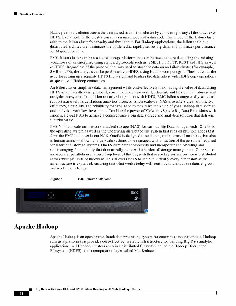
Figure 8 EMC Isilon S200 Node
Apache Hadoop
Apache Hadoop is an open source, batch data processing system for enormous amounts of data. Hadoop runs as a platform that provides cost-effective, scalable infrastructure for building Big Data analytic applications. All Hadoop Clusters contain a distributed filesystem called the Hadoop Distributed Filesystem (HDFS), and a computation layer called MapReduce.
14Big Data with Cisco UCS and EMC Isilon: Building a 60 Node Hadoop Cluster
Solution Overview
Virtualizing Hadoop Clusters
Hadoop is an open source software project that enables the distributed processing of large data sets across clusters of commodity servers. It is designed to scale up from a single server to thousands of machines. Hadoop clusters can be dynamically scaled up and down based on the available resources and the required services levels. Performance service levels vary widely for processing, from a few minutes to multiple days. Hadoop has emerged as a tool of choice for big data analytics, and virtualizing Hadoop brings many benefits, including:
• Rapid provisioning—From the creation of virtual Hadoop nodes to starting up the Hadoop services on the cluster, much of the Hadoop cluster deployment can be automated, requiring little expertise on the user’s part. Virtual Hadoop clusters can be rapidly deployed and configured as needed.
• High availability—Reliability is critical for certain mission-critical uses of Hadoop. HA protection can be provided through the virtualization platform to protect the single points of failure (SPOF) in the Hadoop system, such as the NameNode for HDFS.
• Elasticity—Hadoop capacity can be scaled up and down on demand in a virtual environment, thus allowing the same physical infrastructure to be shared among Hadoop and other applications. This consolidation of workloads results in more efficient resource utilization and reduced costs.
• Multi-tenancy—Different tenants running Hadoop can be isolated in separate VMs, providing stronger VM-grade resource and security isolation. With virtualization, mixed workloads that include non-Hadoop applications can run alongside Hadoop on the same physical cluster.
HDFS and Isilon OneFS
Hadoop works by abstracting from an application the heavy lifting of parallelizing, scheduling and running a job against a large data set. In Hadoop, a user writes a client application that submits one or more jobs. The job contains a map function and a reduce function. The MapReduce framework handles breaking the job into tasks, scheduling tasks to run on machines, and monitoring the tasks. A job processes an input dataset specified by the user and creates an output job one as well. These input and output datasets are one or more files on the Hadoop distributed file system also known as HDFS.
HDFS has three main services: Namenode, Secondary Namenode, and Datanode. The Datanode service is responsible for storing and retrieving blocks. The Namenode stores the filesystem metadata. Clients connect to the Namenode to perform filesystem operations. The third HDFS service is called the secondary Namenode and performs internal housekeeping for the Namenode. Despite its name, the secondary Namenode is not a backup for the Namenode and performs a completely different function. The sole native method of access to HDFS is its Java API. All other access methods are built on top of this API and by definition, can expose only as much functionality as it.
EMC Isilon OneFS implements the essential NameNode and DataNode services on an Isilon cluster by means of a free HDFS license. With EMC Isilon providing HDFS services over the wire through the high-speed 10GigE links, the compute nodes could simply perform the MapReduce tasks for handling all major Hadoop workloads and applications.
VMware vSphere Big Data Extensions
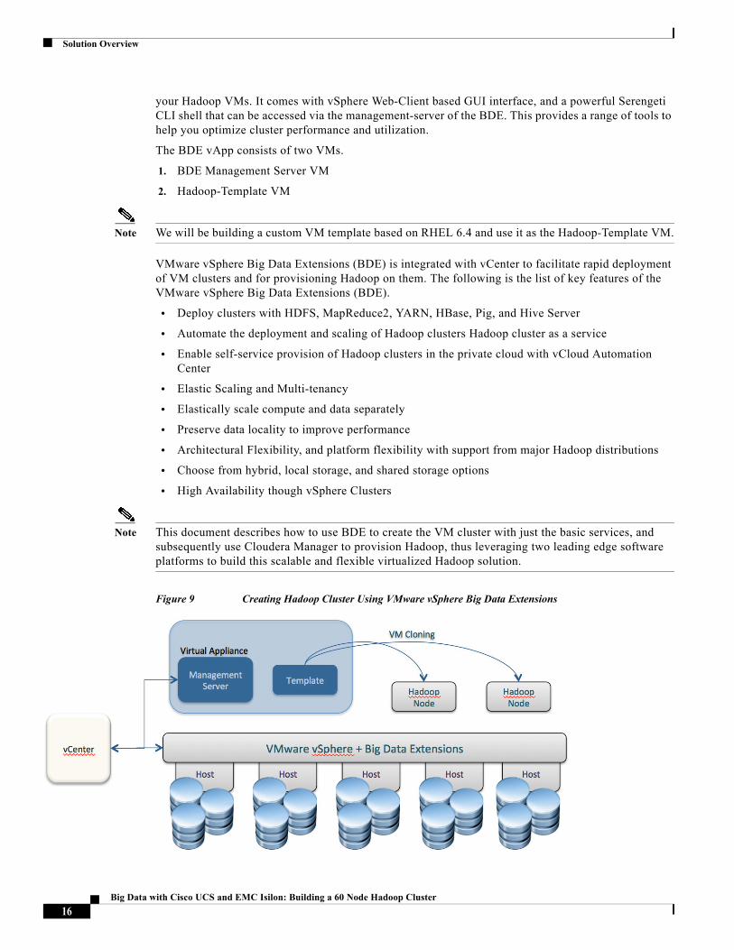
VMware vSphere Big Data Extensions (BDE) is a vApp deployed on a vCenter Server. It helps with the Virtualized Hadoop Cluster deployment and provisioning. It also helps with centralized management of Hadoop clusters VMs via VMware vCenter Server. It allows the user to scale-up/down/out as per the changing needs of the organization, while providing a central place from which to manage and monitor
15Big Data with Cisco UCS and EMC Isilon: Building a 60 Node Hadoop Cluster
Solution Overview
your Hadoop VMs. It comes with vSphere Web-Client based GUI interface, and a powerful Serengeti CLI shell that can be accessed via the management-server of the BDE. This provides a range of tools to help you optimize cluster performance and utilization.
The BDE vApp consists of two VMs.
1. BDE Management Server VM
2. Hadoop-Template VM
Note We will be building a custom VM template based on RHEL 6.4 and use it as the Hadoop-Template VM.
VMware vSphere Big Data Extensions (BDE) is integrated with vCenter to facilitate rapid deployment of VM clusters and for provisioning Hadoop on them. The following is the list of key features of the VMware vSphere Big Data Extensions (BDE).
• Deploy clusters with HDFS, MapReduce2, YARN, HBase, Pig, and Hive Server
• Automate the deployment and scaling of Hadoop clusters Hadoop cluster as a service
• Enable self-service provision of Hadoop clusters in the private cloud with vCloud Automation Center
• Elastic Scaling and Multi-tenancy
• Elastically scale compute and data separately
• Preserve data locality to improve performance
• Architectural Flexibility, and platform flexibility with support from major Hadoop distributions
• Choose from hybrid, local storage, and shared storage options
• High Availability though vSphere Clusters
Note This document describes how to use BDE to create the VM cluster with just the basic services, and subsequently use Cloudera Manager to provision Hadoop, thus leveraging two leading edge software platforms to build this scalable and flexible virtualized Hadoop solution.
Figure 9 Creating Hadoop Cluster Using VMware vSphere Big Data Extensions
16Big Data with Cisco UCS and EMC Isilon: Building a 60 Node Hadoop Cluster
Solution Overview
Cloudera Enterprise CDH 5.2
Cloudera Manager, an end to end management application, is used to install and configure CDH. During
CDH Installation, Cloudera Manager's Wizard will help to install Hadoop services on all nodes using the following procedure:
• Discovery of the cluster VMs
• Configure the Cloudera parcel or package repositories
• Install Hadoop, Cloudera Manager Agent (CMA) and Impala on all the cluster nodes
• Install the Oracle JDK if it is not already installed across all the cluster nodes
• Assign various services to nodes
• Start the Hadoop service
With Cloudera Manager, you can easily deploy and centrally operate the complete Big Data stack. The application automates the installation process, reducing deployment time from weeks to minutes; gives you a cluster-wide, real-time view of nodes and services running; provides a single, central console to enact configuration changes across your cluster; and incorporates a full range of reporting and diagnostic tools to help you optimize performance and utilization.
Key Capabilities of Cloudera Manager
• Manage: Easily deploy, configure and operate a data hub with centralized, intuitive administration for all services, hosts and workflows.
• Monitor: Maintain a central view of all activity in the cluster through heatmaps, proactive health checks and alerts.
• Diagnose: Easily diagnose and resolve issues with operational reports and dashboards, events, intuitive log viewing and search, audit trails and integration with Cloudera Support.
• Integrate: Integrate Cloudera Manager with existing enterprise monitoring tools through SNMP, SMTP and a comprehensive API.
Cloudera Enterprise CDH 5 (5.1.3)
CDH (Cloudera’s Distribution Including Apache Hadoop) is a complete distribution of Apache Hadoop. CDH is open source and it offers batch processing, interactive SQL, and interactive search as well as enterprise-grade continuous availability. CDH delivers the core elements of Hadoop—scalable storage and distributed computing—as well as all of the necessary enterprise capabilities such as security, high availability and integration with a broad range of hardware and software solutions.
Cloudera Enterprise provides a comprehensive platform for designing and managing solutions that cross the boundaries of traditional and Big Data platforms. By providing easy-to-use tools and familiar design concepts for both traditional and Big Data platforms, Cloudera empowers organizations to leverage existing IT skillsets to build Big Data solutions.
Some of the key features of CDH include:
• Flexibility— Store any type of data and prosecute it with an array of different computation frameworks including batch processing, interactive SQL, free text search, machine learning and statistical computation.
• Integration—Get up and running quickly on a complete, packaged, Hadoop platform.
• Security—Process and control sensitive data and facilitate multi-tenancy.
17Big Data with Cisco UCS and EMC Isilon: Building a 60 Node Hadoop Cluster
Solution Architecture
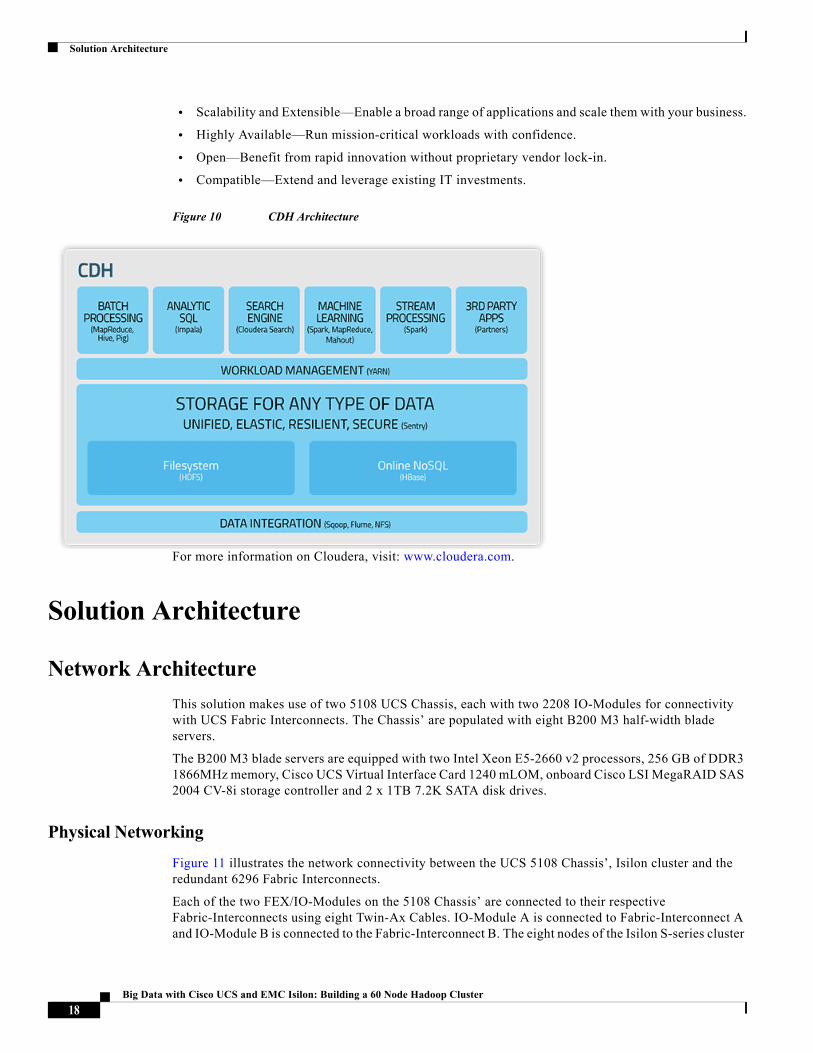
• Scalability and Extensible—Enable a broad range of applications and scale them with your business.
• Highly Available—Run mission-critical workloads with confidence.
• Open—Benefit from rapid innovation without proprietary vendor lock-in.
• Compatible—Extend and leverage existing IT investments.
Figure 10 CDH Architecture
For more information on Cloudera, visit: www.cloudera.com.
Solution Architecture
Network Architecture
This solution makes use of two 5108 UCS Chassis, each with two 2208 IO-Modules for connectivity with UCS Fabric Interconnects. The Chassis’ are populated with eight B200 M3 half-width blade servers.
The B200 M3 blade servers are equipped with two Intel Xeon E5-2660 v2 processors, 256 GB of DDR3 1866MHz memory, Cisco UCS Virtual Interface Card 1240 mLOM, onboard Cisco LSI MegaRAID SAS 2004 CV-8i storage controller and 2 x 1TB 7.2K SATA disk drives.
Physical Networking
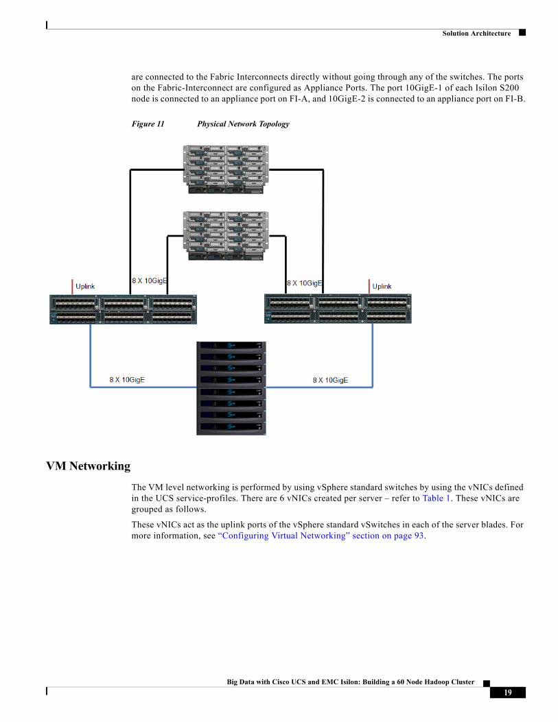
Figure 11 illustrates the network connectivity between the UCS 5108 Chassis’, Isilon cluster and the redundant 6296 Fabric Interconnects.
Each of the two FEX/IO-Modules on the 5108 Chassis’ are connected to their respective Fabric-Interconnects using eight Twin-Ax Cables. IO-Module A is connected to Fabric-Interconnect A and IO-Module B is connected to the Fabric-Interconnect B. The eight nodes of the Isilon S-series cluster
18Big Data with Cisco UCS and EMC Isilon: Building a 60 Node Hadoop Cluster
Solution Architecture
are connected to the Fabric Interconnects directly without going through any of the switches. The ports on the Fabric-Interconnect are configured as Appliance Ports. The port 10GigE-1 of each Isilon S200 node is connected to an appliance port on FI-A, and 10GigE-2 is connected to an appliance port on FI-B.
Figure 11 Physical Network Topology
VM Networking
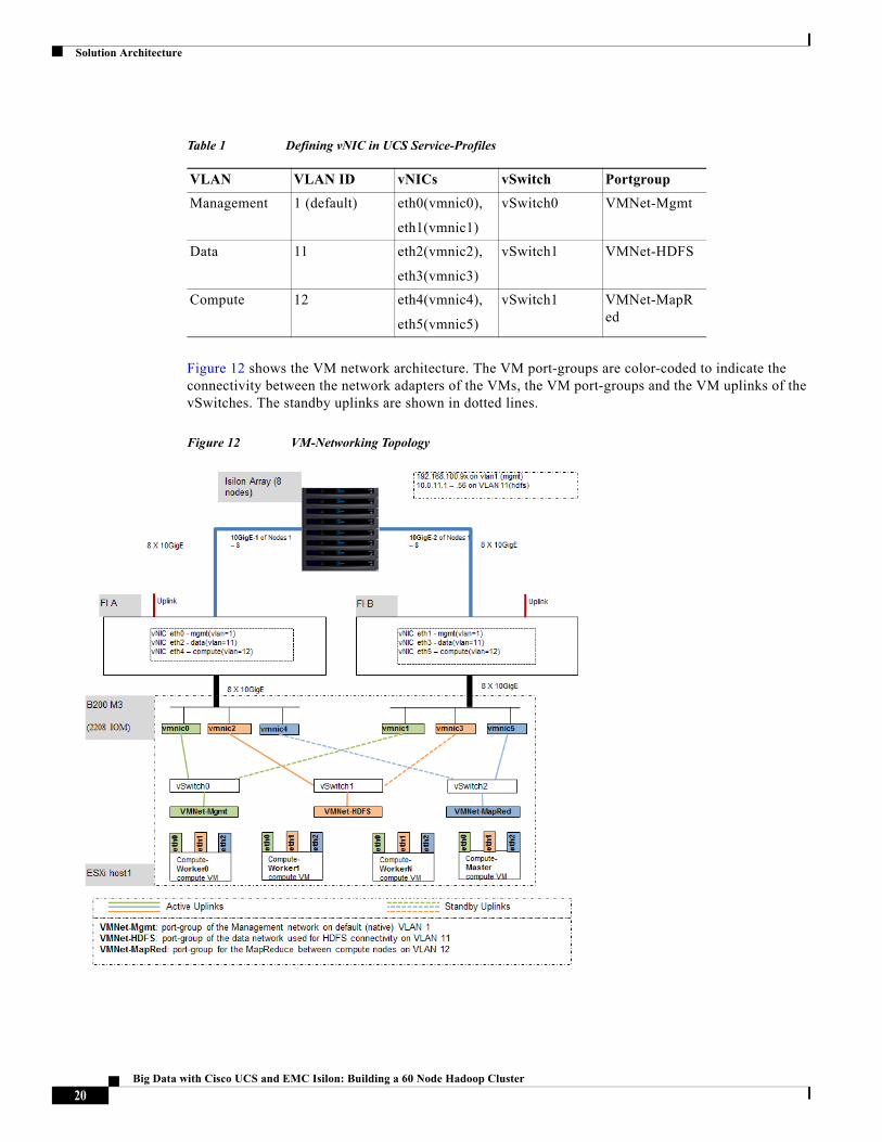
The VM level networking is performed by using vSphere standard switches by using the vNICs defined in the UCS service-profiles. There are 6 vNICs created per server – refer to Table 1. These vNICs are grouped as follows.
These vNICs act as the uplink ports of the vSphere standard vSwitches in each of the server blades. For more information, see “Configuring Virtual Networking” section on page 93.
19Big Data with Cisco UCS and EMC Isilon: Building a 60 Node Hadoop Cluster
Solution Architecture
Figure 12 shows the VM network architecture. The VM port-groups are color-coded to indicate the connectivity between the network adapters of the VMs, the VM port-groups and the VM uplinks of the vSwitches. The standby uplinks are shown in dotted lines.
Figure 12 VM-Networking Topology
Table 1 Defining vNIC in UCS Service-Profiles
VLAN VLAN ID vNICs vSwitch Portgroup
Management 1 (default) eth0(vmnic0),
eth1(vmnic1)
vSwitch0 VMNet-Mgmt
Data 11 eth2(vmnic2),
eth3(vmnic3)
vSwitch1 VMNet-HDFS
Compute 12 eth4(vmnic4),
eth5(vmnic5)
vSwitch1 VMNet-MapRed
20Big Data with Cisco UCS and EMC Isilon: Building a 60 Node Hadoop Cluster
Solution Architecture
Software Infrastructure
This document talks about the method to create a self-contained infrastructure for Virtualized Hadoop that can be used to provision multiple Hadoop clusters and scaling them to satisfy the needs of today’s enterprise customers.
This Virtualized Hadoop solution is built with the following software components:
• Cisco UCS Manager for provisioning the UCS blades
• Isilon OneFS for providing HDFS services
• vSphere ESXi Hypervisors running on all 16 blade servers
• vCenter Server appliance
• vSphere Big Data Extensions vApp for virtualized Hadoop deployment
• RHEL6.4-based Custom OS- VM template to be used with the BDE vApp
• RHEL6.4-based Admin-VM that runs DHCP, DNS, NTP services. It also hosts RHEL and Hadoop distribution repositories.
• Cloudera Distribution for Apache Hadoop (CDH 5.1.34)
• Cloudera Manager (CM 5.2.0)
In the following sections, we will see how to install and configure each one of these software infrastructure components for building the Virtualized Hadoop solution.
vSphere Clusters and Distributed Resource Scheduler (DRS)
VMware vSphere Big Data Extensions requires the compute resources be managed in the form of vSphere clusters for building a Virtualized Hadoop solution. Thus, the compute resources i.e. ESXi hosts of this solution were managed by grouping them as vSphere clusters.
VMware vSphere clusters allow you to:
• Provide highly available resources to your workloads.
• Balance workloads for optimal performance.
• Scale and manage computing resources without service disruption.
Balancing Compute Capacity Using vSphere Distributed Resource Scheduler (DRS)
The computing capacity is balanced in the cluster to deliver optimized performance for hosts and virtual machines.
VMware vSphere Distributed Resource Scheduler (DRS) is a feature included in the vSphere Enterprise and Enterprise Plus editions. Using DRS, you can:
• Improve service levels by guaranteeing appropriate resources to virtual machines.
• Deploy new capacity (i.e. adding a new ESXi-host) to a cluster without service disruption.
• Migrating virtual machines automatically during maintenance without service disruption (requires vSphere vMotion).
• Monitor and manage more infrastructures per system administrator.
The DRS manages various stages of VM deployment such as:
21Big Data with Cisco UCS and EMC Isilon: Building a 60 Node Hadoop Cluster
Solution Architecture
• Initial VM placement—When a VM is powered on in a cluster, DRS could place it on an appropriate host or generates a recommendation, depending on the automation level you choose. In this solution, BDE makes use of this feature for placing Hadoop cluster VMs.
• Automated load-balancing—DRS spread the virtual machine workloads across vSphere hosts inside a cluster and constantly available resources for you. Depending on the automation levels chosen, DRS could migrate the VMs other hosts within the cluster to maximize performance (requires vSphere vMotion).
Note Since, we did not enable vMotion in this solution, we disabled the application-monitoring and migration features in the cluster.
• Cluster Maintenance—DRS speeds up the VMware vSphere Update Manager remediation process by determining the optimum number of hosts that can enter maintenance mode simultaneously, based on current cluster conditions and demands.
We created and made use of two compute resource clusters in this solution. Hereafter, we will be referring to them as DRS-cluster.
• Admin DRS-cluster—consists of the ESXi hosts in which the administrative VMs (vSphere vCenter Server, vSphere Big Data Extensions vApp, Admin-VM) are placed.
• Hadoop DRS-cluster— consists of ESXi hosts in which the Hadoop Cluster VMs are placed by using BDE.
In this solution, we kept only one ESXi host in the Admin DRS-cluster and the other fifteen ESXi hosts were put in the Hadoop DRS-cluster. However, one could easily add more compute resources to this pool to match the deployment needs.
Managing Resources In BDE
In order to provision Virtualized Hadoop, BDE requires three types of resources.
1. Compute resource pool – maps to the Hadoop DRS-cluster we discussed in the previous section.
2. Network resources – these are pointers to the actual vSphere port-groups defined in the ESXi vSwitches.
3. Datastore pool – a pool of datastore pools utilized for placing the VM hard-drives for the Hadoop VMs.
The “Configuring Datastores and Network Resources in Big Data Extensions” section on page 170 shows the creation of the network and datastore resources in BDE.
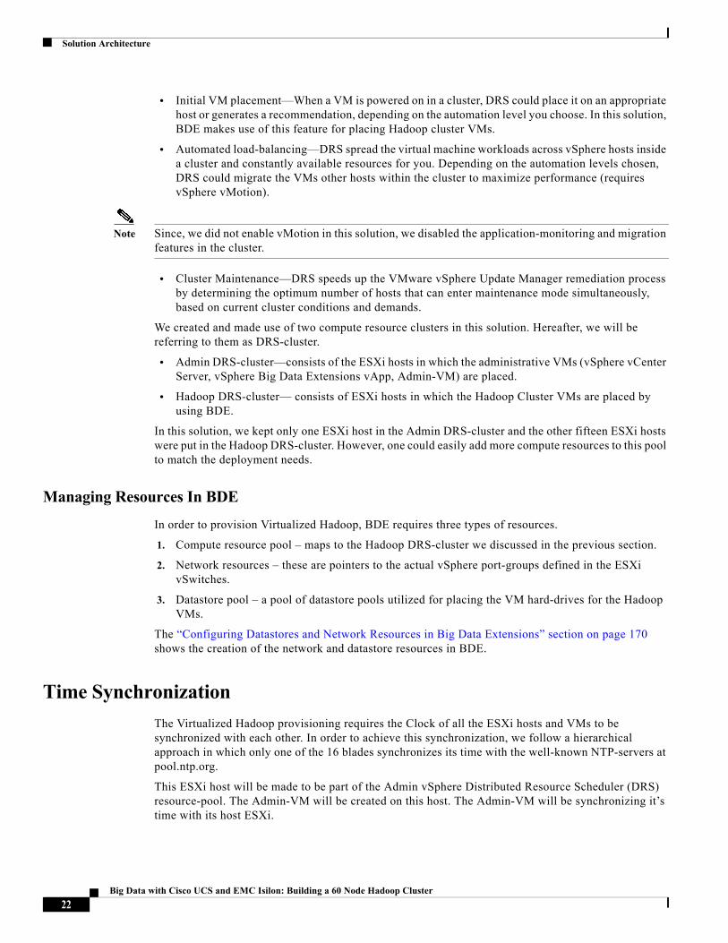
Time Synchronization
The Virtualized Hadoop provisioning requires the Clock of all the ESXi hosts and VMs to be synchronized with each other. In order to achieve this synchronization, we follow a hierarchical approach in which only one of the 16 blades synchronizes its time with the well-known NTP-servers at pool.ntp.org.
This ESXi host will be made to be part of the Admin vSphere Distributed Resource Scheduler (DRS) resource-pool. The Admin-VM will be created on this host. The Admin-VM will be synchronizing it’s time with its host ESXi.
22Big Data with Cisco UCS and EMC Isilon: Building a 60 Node Hadoop Cluster
Rack and PDU Configuration
All the other 15 ESXi hosts that are to be part of the Hadoop DRS-cluster shall synchronize their clock to the Admin-VM’s NTP-server.
The Hadoop-Cluster VMs themselves will synchronize their clock to their respective ESXi host. By following the hierarchical approach shown below, the timing is synchronized and maintained across the entire cluster.
Figure 13 NTP Synchronization Scheme
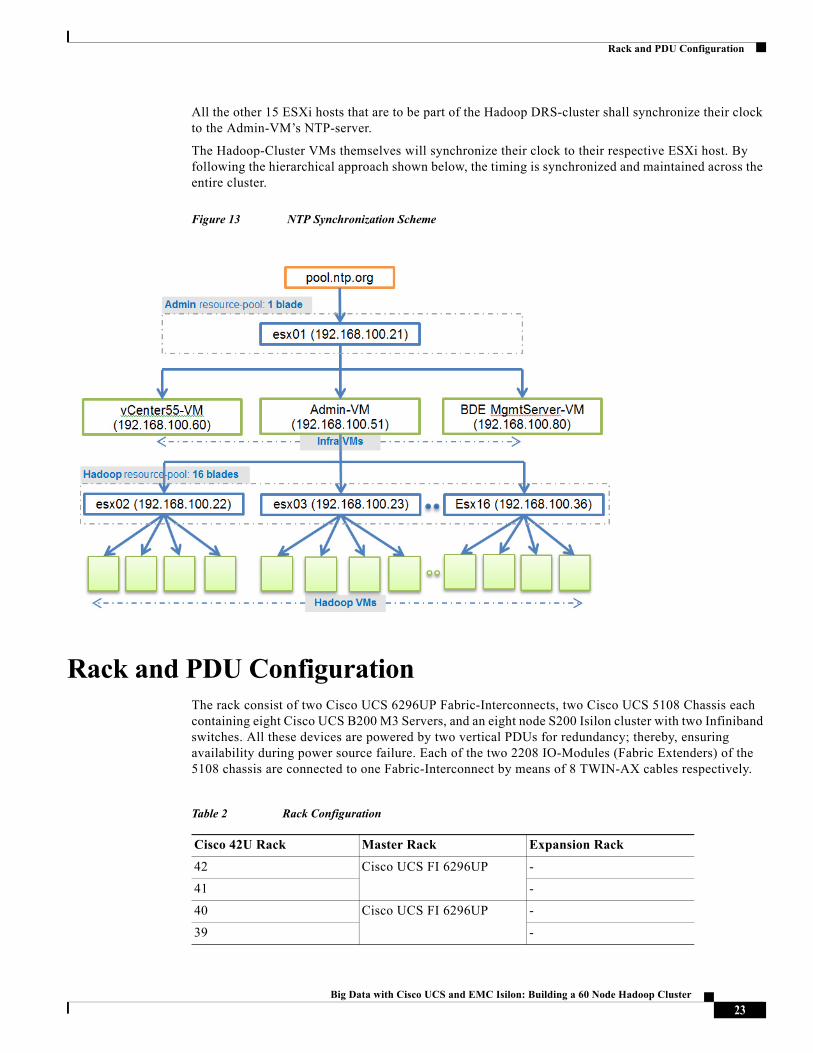
Rack and PDU ConfigurationThe rack consist of two Cisco UCS 6296UP Fabric-Interconnects, two Cisco UCS 5108 Chassis each containing eight Cisco UCS B200 M3 Servers, and an eight node S200 Isilon cluster with two Infiniband switches. All these devices are powered by two vertical PDUs for redundancy; thereby, ensuring availability during power source failure. Each of the two 2208 IO-Modules (Fabric Extenders) of the 5108 chassis are connected to one Fabric-Interconnect by means of 8 TWIN-AX cables respectively.
Table 2 Rack Configuration
Cisco 42U Rack Master Rack Expansion Rack
42 Cisco UCS FI 6296UP -
41 -
40 Cisco UCS FI 6296UP -
39 -
23Big Data with Cisco UCS and EMC Isilon: Building a 60 Node Hadoop Cluster
Rack and PDU Configuration
38 - -
37 - -
36 - -
35 - -
34 - -
33 - -
32 - -
31 - -
30 IB Switch -
29 -
28 IsilonS200 Isilon S200
27
26 Isilon S200 Isilon S200
25
24 Isilon S200 Isilon S200
23
22 Isilon S200 Isilon S200
21
20 Isilon S200 Isilon S200
19
18 Isilon S200 Isilon S200
17
16 Isilon S200 Isilon S200
15
14 Isilon S200 Isilon S200
13
12 Cisco UCS 5108 Blade Server Chassis
Cisco UCS 5108 Blade Server Chassis11
10
9
8
7
Table 2 Rack Configuration
Cisco 42U Rack Master Rack Expansion Rack
24Big Data with Cisco UCS and EMC Isilon: Building a 60 Node Hadoop Cluster
Rack and PDU Configuration
Note Please contact your Cisco or EMC representatives for country specific information.
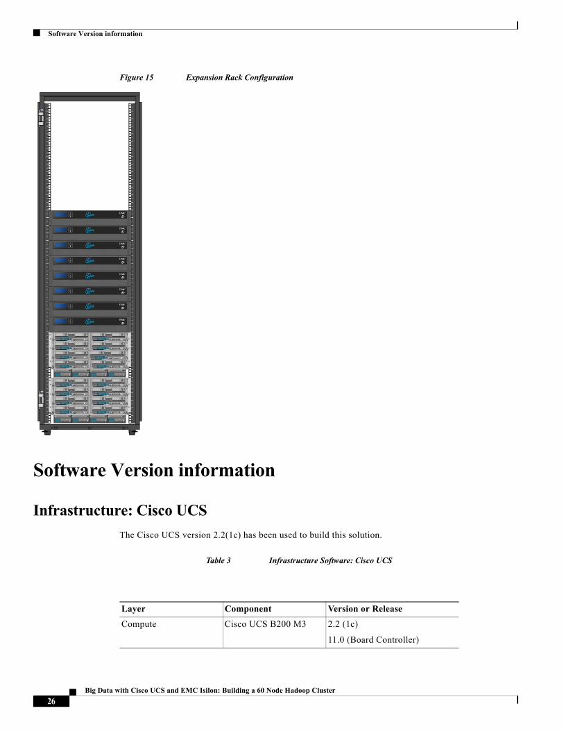
Figure 14 and Figure 15 show the physical view (front) of the master and expansion rack.
Figure 14 Master Rack Configuration
6 Cisco UCS 5108 Blade Server Chassis
Cisco UCS 5108 Blade Server Chassis5
4
3
2
1
Table 2 Rack Configuration
Cisco 42U Rack Master Rack Expansion Rack
25Big Data with Cisco UCS and EMC Isilon: Building a 60 Node Hadoop Cluster
Software Version information
Figure 15 Expansion Rack Configuration
Software Version information
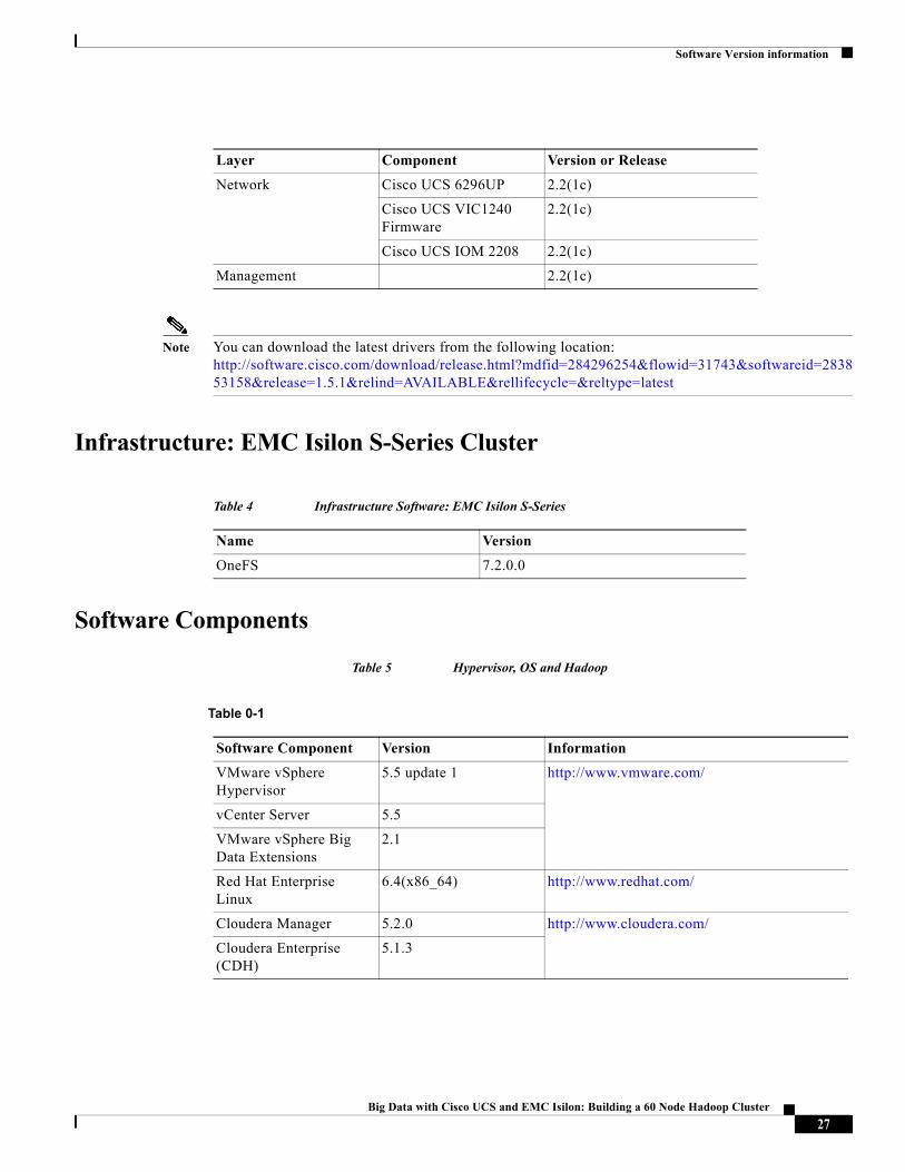
Infrastructure: Cisco UCS
The Cisco UCS version 2.2(1c) has been used to build this solution.
Table 3 Infrastructure Software: Cisco UCS
Layer Component Version or Release
Compute Cisco UCS B200 M3 2.2 (1c)
11.0 (Board Controller)
26Big Data with Cisco UCS and EMC Isilon: Building a 60 Node Hadoop Cluster
Software Version information
Note You can download the latest drivers from the following location: http://software.cisco.com/download/release.html?mdfid=284296254&flowid=31743&softwareid=283853158&release=1.5.1&relind=AVAILABLE&rellifecycle=&reltype=latest
Infrastructure: EMC Isilon S-Series Cluster
Software Components
Table 5 Hypervisor, OS and Hadoop
Network Cisco UCS 6296UP 2.2(1c)
Cisco UCS VIC1240 Firmware
2.2(1c)
Cisco UCS IOM 2208 2.2(1c)
Management 2.2(1c)
Layer Component Version or Release
Table 4 Infrastructure Software: EMC Isilon S-Series
Name Version
OneFS 7.2.0.0
Table 0-1
Software Component Version Information
VMware vSphere Hypervisor
5.5 update 1 http://www.vmware.com/
vCenter Server 5.5
VMware vSphere Big Data Extensions
2.1
Red Hat Enterprise Linux
6.4(x86_64) http://www.redhat.com/
Cloudera Manager 5.2.0 http://www.cloudera.com/
Cloudera Enterprise (CDH)
5.1.3
27Big Data with Cisco UCS and EMC Isilon: Building a 60 Node Hadoop Cluster
Unified Fabric Configuration
Unified Fabric Configuration This section provides details for configuring a fully redundant, highly available Cisco UCS 6296 fabric configuration.
Initial setup of the Fabric Interconnect A and B
1. Connect to IP address of Fabric Interconnect A using web browser.
2. Launch UCS Manager.
3. Edit the chassis discovery policy.
4. Enable server and uplink ports.
5. Enable Appliance ports for Isilon connectivity
6. Create pools and polices for service profile template.
7. Create Service Profile template and 16 Service profiles.
8. Start server discovery process.
9. Associate to server.
Performing Initial Setup of Cisco UCS 6296 Fabric Interconnects
This section describes the steps to perform initial setup of the Cisco UCS 6296 Fabric Interconnects A and B.
Configure Fabric Interconnect A
1. Connect to the console port on the first Cisco UCS 6296 Fabric Interconnect.
2. At the prompt to enter the configuration method, enter console to continue.
3. If asked to either perform a new setup or restore from backup, enter setup to continue.
4. Enter y to continue to set up a new Fabric Interconnect.
5. Enter y to enforce strong passwords.
6. Enter the password for the admin user.
7. Enter the same password again to confirm the password for the admin user.
8. When asked if this fabric interconnect is part of a cluster, answer y to continue.
9. Enter A for the switch fabric.
10. Enter the cluster name for the system name.
11. Enter the Mgmt0 IPv4 address.
12. Enter the Mgmt0 IPv4 netmask.
13. Enter the IPv4 address of the default gateway.
14. Enter the cluster IPv4 address.
15. To configure DNS, answer y.
16. Enter the DNS IPv4 address.
17. Answer y to set up the default domain name.
28Big Data with Cisco UCS and EMC Isilon: Building a 60 Node Hadoop Cluster
Unified Fabric Configuration
18. Enter the default domain name.
19. Review the settings that were printed to the console, and if they are correct, answer yes to save the configuration.
20. Wait for the login prompt to make sure the configuration has been saved.
Configure Fabric Interconnect B
1. Connect to the console port on the second Cisco UCS 6296 Fabric Interconnect.
2. When prompted to enter the configuration method, enter console to continue.
3. The installer detects the presence of the partner Fabric Interconnect and adds this fabric interconnect to the cluster. Enter y to continue the installation.
4. Enter the admin password that was configured for the first Fabric Interconnect.
5. Enter the Mgmt0 IPv4 address.
6. Answer yes to save the configuration.
7. Wait for the login prompt to confirm that the configuration has been saved.
For more information on configuring Cisco UCS 6200 Series Fabric Interconnect, see:
http://www.cisco.com/c/en/us/td/docs/unified_computing/ucs/sw/gui/config/guide/2-2/b_UCSM_GUI_Configuration_Guide_2_2.html
Logging Into Cisco UCS Manager
Follow these steps to login to Cisco UCS Manager:
1. Open a Web browser and navigate to the Cisco UCS 6296 Fabric Interconnect cluster address.
2. Click the Launch link to download the Cisco UCS Manager software.
3. If prompted to accept security certificates, accept as necessary.
4. When prompted, enter admin for the username and enter the administrative password.
5. Click Login to log in to the Cisco UCS Manager.
Upgrading UCSM Software to Version 2.2(1c)
In this section, we will document the process of upgrading the UCS firmware to the version UCS 2.2(1c). If your current UCS firmware version is 2.1, please refer to Upgrading between Cisco UCS 2.x Releases to upgrade the Cisco UCS Manager to identify and upgrade your UCS firmware. Please do make sure that the UCS B-Series version 2.2(1c) software bundles is installed on the Fabric Interconnects.
UCS Configurations
Adding Block of IP Addresses for KVM Access
These steps provide details for creating a block of KVM IP addresses for server access in the Cisco UCS environment.
1. Choose the LAN tab at the top of the left window.
29Big Data with Cisco UCS and EMC Isilon: Building a 60 Node Hadoop Cluster
Unified Fabric Configuration
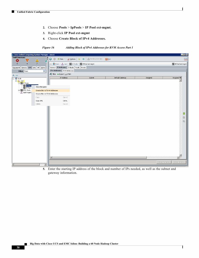
2. Choose Pools > IpPools > IP Pool ext-mgmt.
3. Right-click IP Pool ext-mgmt
4. Choose Create Block of IPv4 Addresses.
Figure 16 Adding Block of IPv4 Addresses for KVM Access Part 1
5. Enter the starting IP address of the block and number of IPs needed, as well as the subnet and gateway information.
30Big Data with Cisco UCS and EMC Isilon: Building a 60 Node Hadoop Cluster
Unified Fabric Configuration
Figure 17 Adding Block of IPv4 Addresses for KVM Access Part 2
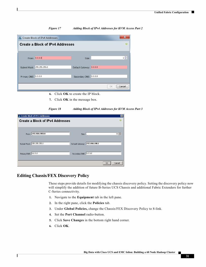
6. Click OK to create the IP block.
7. Click OK in the message box.
Figure 18 Adding Block of IPv4 Addresses for KVM Access Part 3
Editing Chassis/FEX Discovery Policy
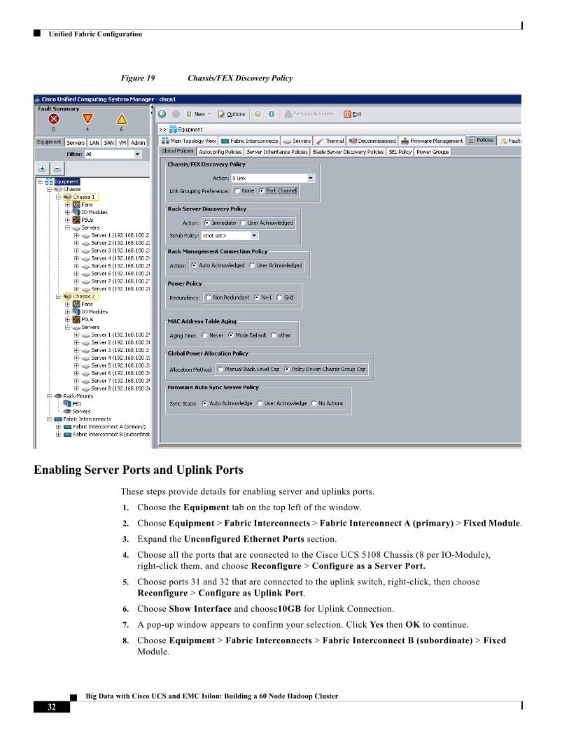
These steps provide details for modifying the chassis discovery policy. Setting the discovery policy now will simplify the addition of future B-Series UCS Chassis and additional Fabric Extenders for further C-Series connectivity.
1. Navigate to the Equipment tab in the left pane.
2. In the right pane, click the Policies tab.
3. Under Global Policies, change the Chassis/FEX Discovery Policy to 8-link.
4. Set the Port Channel radio-button.
5. Click Save Changes in the bottom right hand corner.
6. Click OK.
31Big Data with Cisco UCS and EMC Isilon: Building a 60 Node Hadoop Cluster
Unified Fabric Configuration
Figure 19 Chassis/FEX Discovery Policy
Enabling Server Ports and Uplink Ports
These steps provide details for enabling server and uplinks ports.
1. Choose the Equipment tab on the top left of the window.
2. Choose Equipment > Fabric Interconnects > Fabric Interconnect A (primary) > Fixed Module.
3. Expand the Unconfigured Ethernet Ports section.
4. Choose all the ports that are connected to the Cisco UCS 5108 Chassis (8 per IO-Module), right-click them, and choose Reconfigure > Configure as a Server Port.
5. Choose ports 31 and 32 that are connected to the uplink switch, right-click, then choose Reconfigure > Configure as Uplink Port.
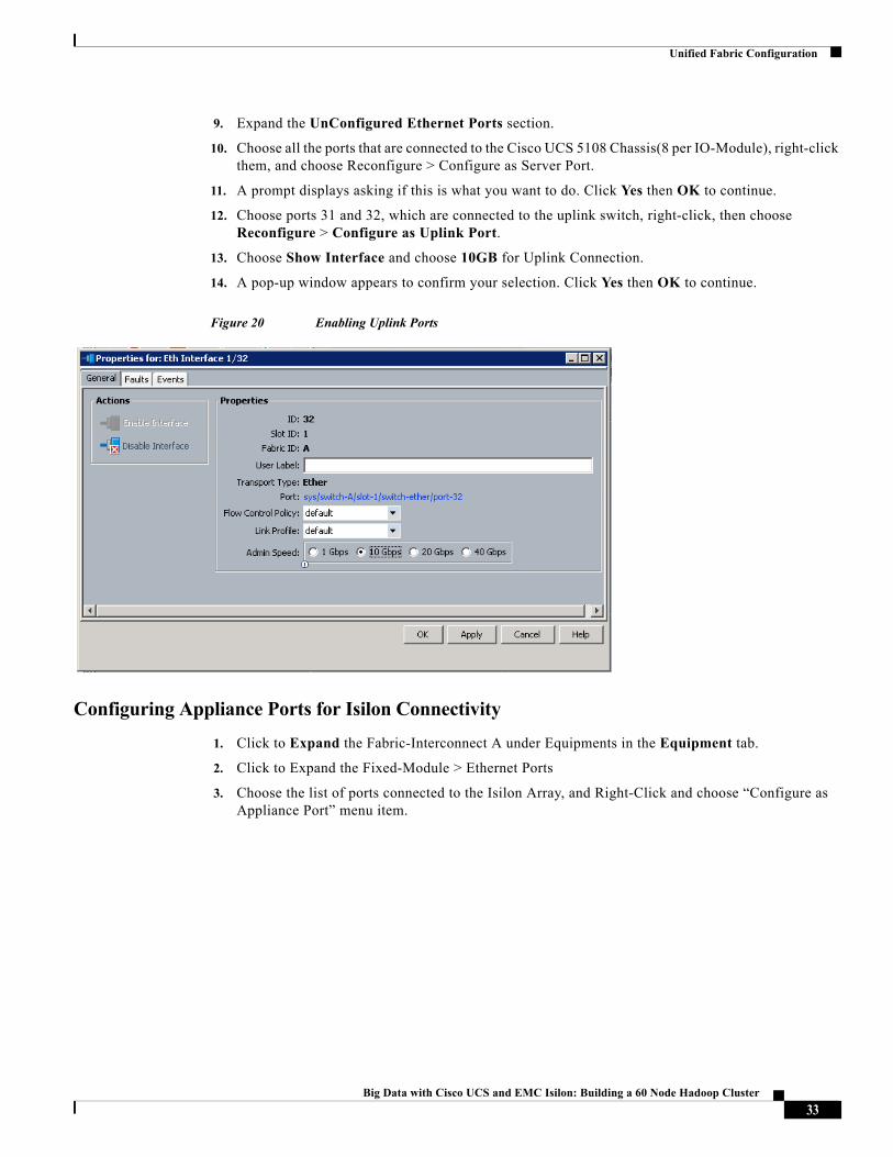
6. Choose Show Interface and choose10GB for Uplink Connection.
7. A pop-up window appears to confirm your selection. Click Yes then OK to continue.
8. Choose Equipment > Fabric Interconnects > Fabric Interconnect B (subordinate) > Fixed Module.
32Big Data with Cisco UCS and EMC Isilon: Building a 60 Node Hadoop Cluster
Unified Fabric Configuration
9. Expand the UnConfigured Ethernet Ports section.
10. Choose all the ports that are connected to the Cisco UCS 5108 Chassis(8 per IO-Module), right-click them, and choose Reconfigure > Configure as Server Port.
11. A prompt displays asking if this is what you want to do. Click Yes then OK to continue.
12. Choose ports 31 and 32, which are connected to the uplink switch, right-click, then choose Reconfigure > Configure as Uplink Port.
13. Choose Show Interface and choose 10GB for Uplink Connection.
14. A pop-up window appears to confirm your selection. Click Yes then OK to continue.
Figure 20 Enabling Uplink Ports
Configuring Appliance Ports for Isilon Connectivity
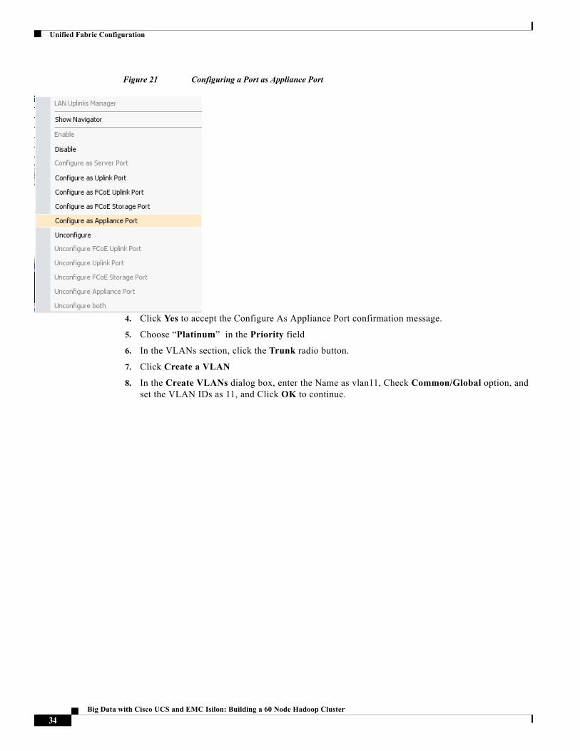
1. Click to Expand the Fabric-Interconnect A under Equipments in the Equipment tab.
2. Click to Expand the Fixed-Module > Ethernet Ports
3. Choose the list of ports connected to the Isilon Array, and Right-Click and choose “Configure as Appliance Port” menu item.
33Big Data with Cisco UCS and EMC Isilon: Building a 60 Node Hadoop Cluster
Unified Fabric Configuration
Figure 21 Configuring a Port as Appliance Port
4. Click Yes to accept the Configure As Appliance Port confirmation message.
5. Choose “Platinum” in the Priority field
6. In the VLANs section, click the Trunk radio button.
7. Click Create a VLAN
8. In the Create VLANs dialog box, enter the Name as vlan11, Check Common/Global option, and set the VLAN IDs as 11, and Click OK to continue.
34Big Data with Cisco UCS and EMC Isilon: Building a 60 Node Hadoop Cluster
Unified Fabric Configuration
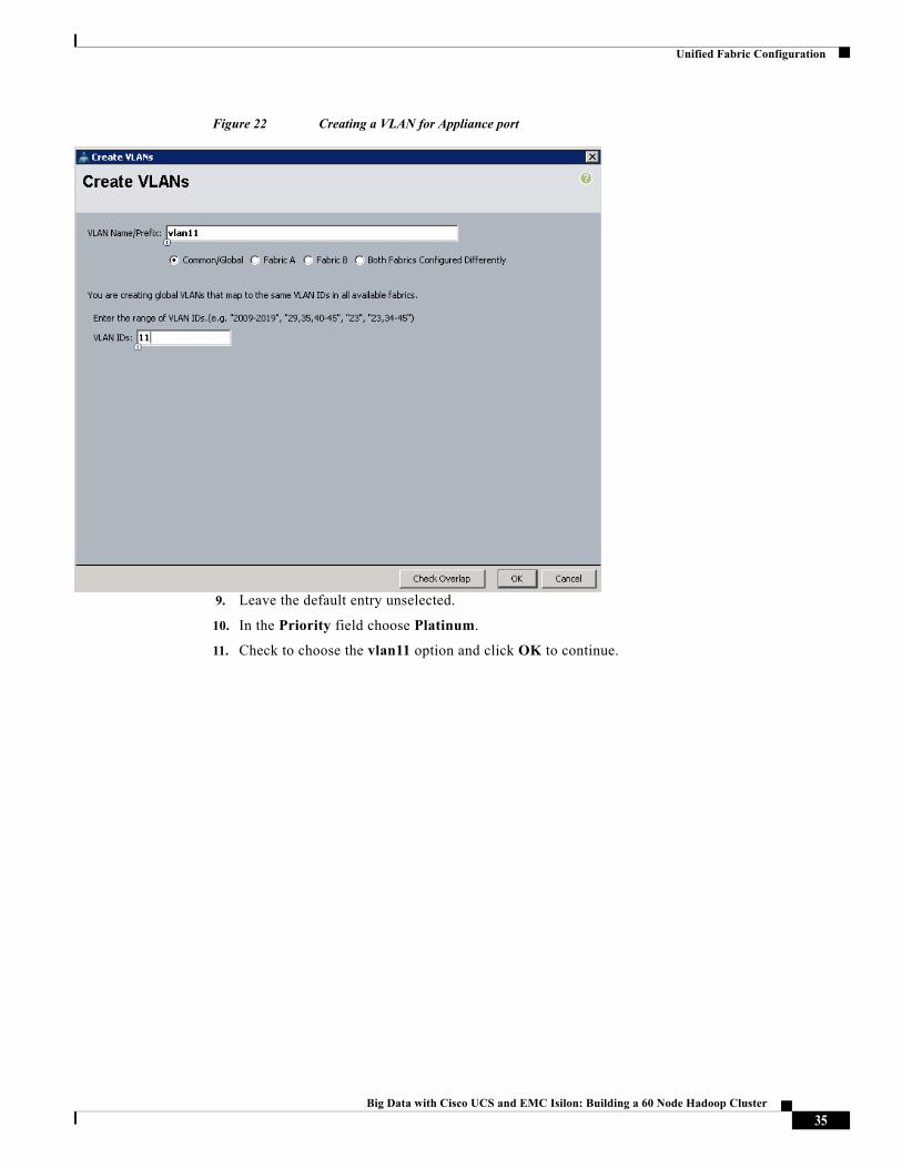
Figure 22 Creating a VLAN for Appliance port
9. Leave the default entry unselected.
10. In the Priority field choose Platinum.
11. Check to choose the vlan11 option and click OK to continue.
35Big Data with Cisco UCS and EMC Isilon: Building a 60 Node Hadoop Cluster
Unified Fabric Configuration
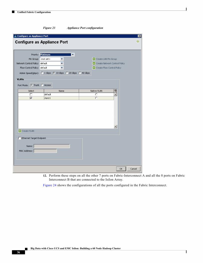
Figure 23 Appliance Port configuration
12. Perform these steps on all the other 7 ports on Fabric-Interconnect A and all the 8 ports on Fabric Interconnect B that are connected to the Isilon Array.
Figure 24 shows the configurations of all the ports configured in the Fabric Interconnect.
36Big Data with Cisco UCS and EMC Isilon: Building a 60 Node Hadoop Cluster
Unified Fabric Configuration
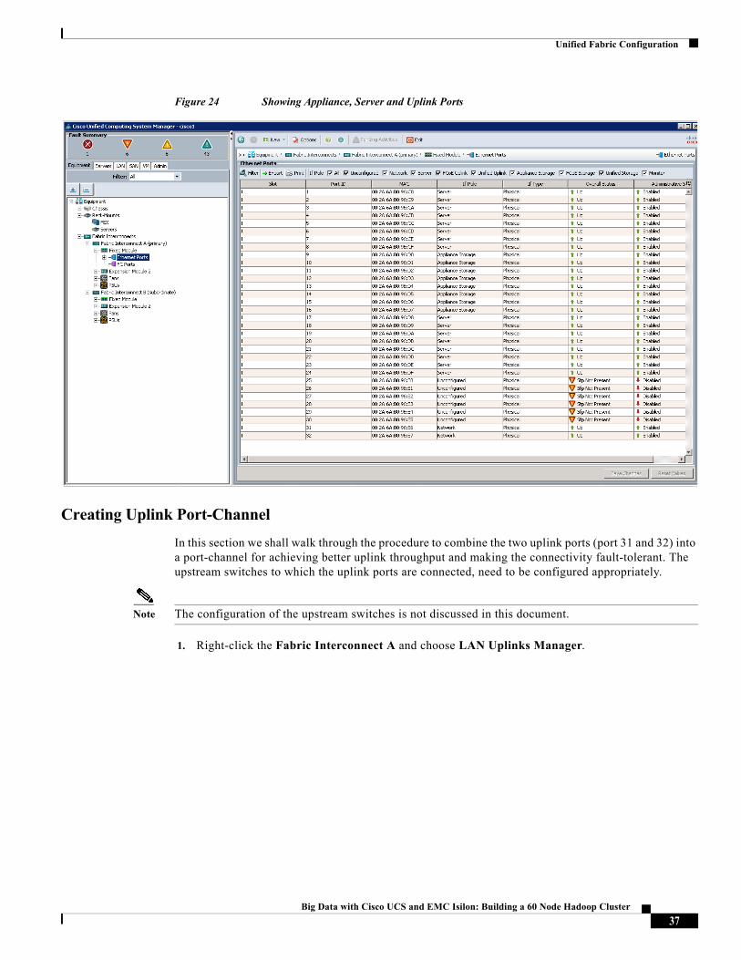
Figure 24 Showing Appliance, Server and Uplink Ports
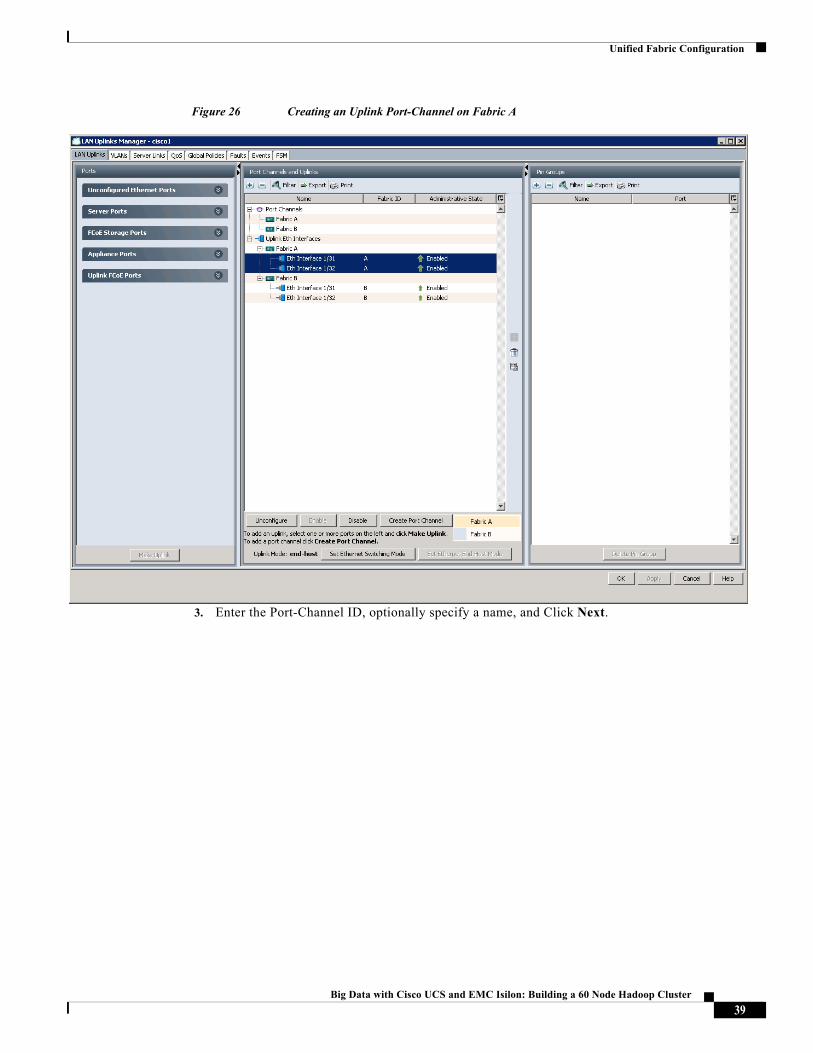
Creating Uplink Port-Channel
In this section we shall walk through the procedure to combine the two uplink ports (port 31 and 32) into a port-channel for achieving better uplink throughput and making the connectivity fault-tolerant. The upstream switches to which the uplink ports are connected, need to be configured appropriately.
Note The configuration of the upstream switches is not discussed in this document.
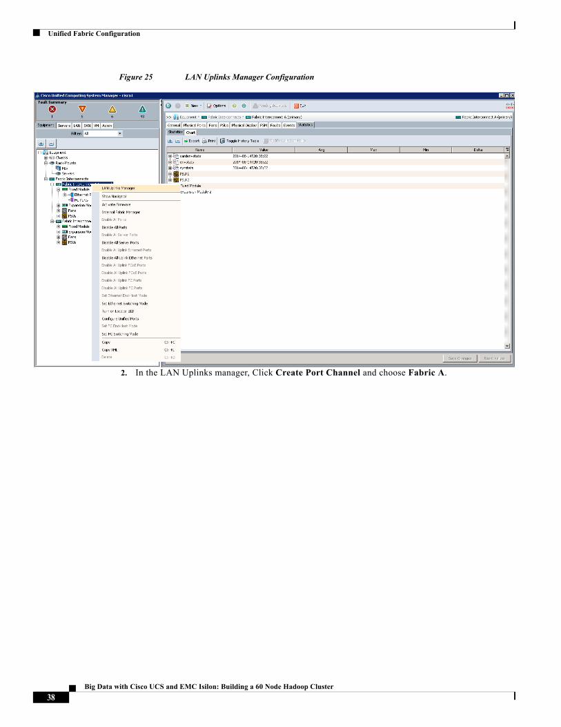
1. Right-click the Fabric Interconnect A and choose LAN Uplinks Manager.
37Big Data with Cisco UCS and EMC Isilon: Building a 60 Node Hadoop Cluster
Unified Fabric Configuration
Figure 25 LAN Uplinks Manager Configuration
2. In the LAN Uplinks manager, Click Create Port Channel and choose Fabric A.
38Big Data with Cisco UCS and EMC Isilon: Building a 60 Node Hadoop Cluster
Unified Fabric Configuration
Figure 26 Creating an Uplink Port-Channel on Fabric A
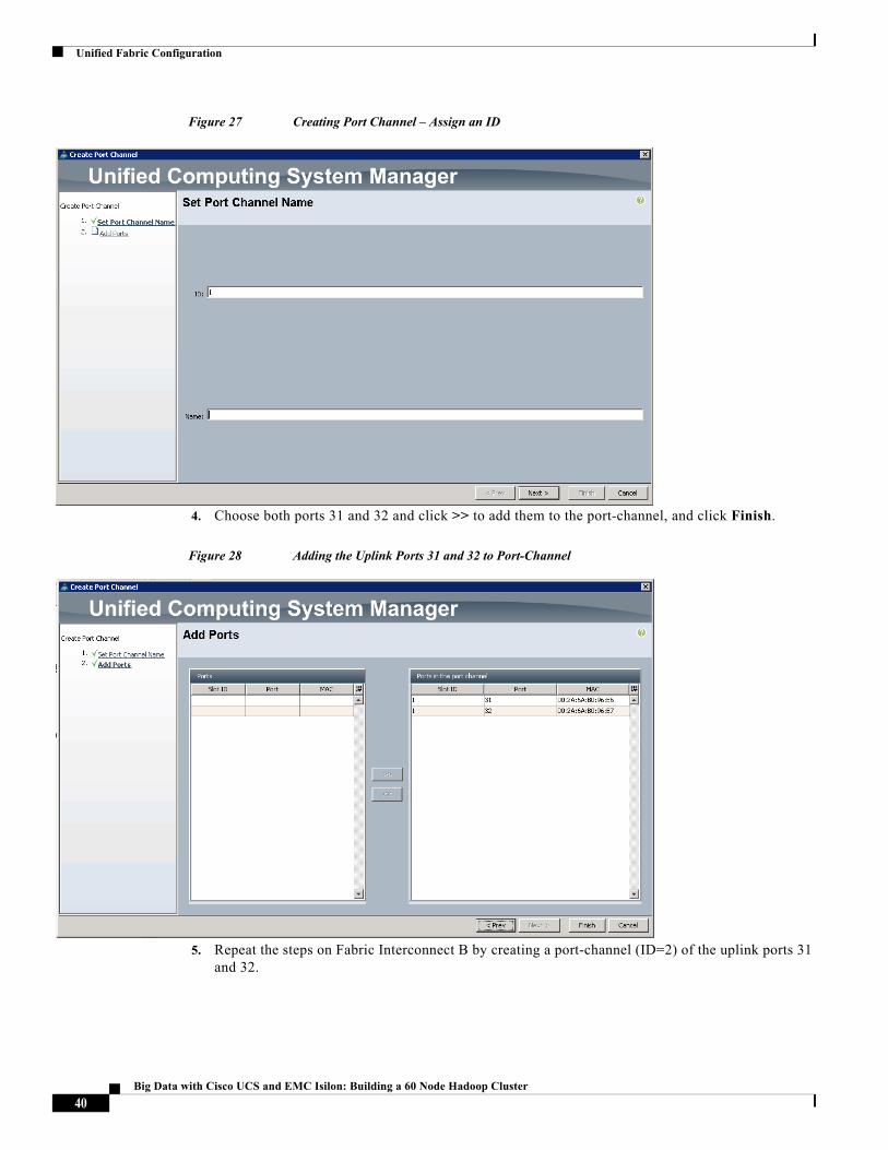
3. Enter the Port-Channel ID, optionally specify a name, and Click Next.
39Big Data with Cisco UCS and EMC Isilon: Building a 60 Node Hadoop Cluster
Unified Fabric Configuration
Figure 27 Creating Port Channel – Assign an ID
4. Choose both ports 31 and 32 and click >> to add them to the port-channel, and click Finish.
Figure 28 Adding the Uplink Ports 31 and 32 to Port-Channel
5. Repeat the steps on Fabric Interconnect B by creating a port-channel (ID=2) of the uplink ports 31 and 32.
40Big Data with Cisco UCS and EMC Isilon: Building a 60 Node Hadoop Cluster
Creating Pools for Service Profile Templates
Note The upstream switches will need to be configured to match these Port-Channel configurations in order to establish the proper connectivity upstream.
Creating Pools for Service Profile TemplatesThis section provides information on creating various pools for Service Profile Templates.
Creating an Organization
Organizations are used as a means to arrange and restrict access to various groups within the IT organization, thereby enabling multi-tenancy of the compute resources. This document does not assume the use of Organizations; however the necessary steps are provided for future reference.
Follow these steps to configure an organization within the Cisco UCS Manager GUI:
1. Click New on the top left corner in the right pane in the UCS Manager GUI.
2. Choose Create Organization from the options
3. Enter a name for the organization.
4. (Optional) Enter a description for the organization.
5. Click OK.
6. Click OK in the success message box.
Creating MAC Address Pools
Follow these steps to create MAC address pools:
1. Choose the LAN tab on the left of the window.
2. Choose Pools > root.
3. Right-click MAC Pools under the root organization.
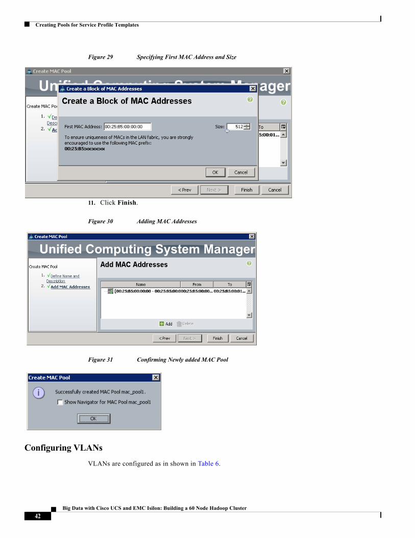
4. Choose Create MAC Pool option to create the MAC address pool. Enter “mac_pool1” for the name of the MAC pool.
5. (Optional) Enter a description of the MAC pool.
6. Click Next.
7. Click Add.
8. Specify a starting MAC address.
9. Specify a size of the MAC address pool, which is sufficient to support the available server resources.
10. Click OK.
41Big Data with Cisco UCS and EMC Isilon: Building a 60 Node Hadoop Cluster
Creating Pools for Service Profile Templates
Figure 29 Specifying First MAC Address and Size
11. Click Finish.
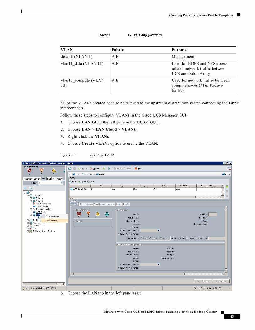
Figure 30 Adding MAC Addresses
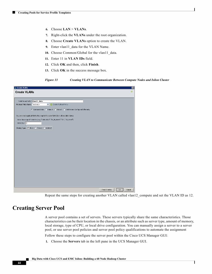
Figure 31 Confirming Newly added MAC Pool
Configuring VLANs
VLANs are configured as in shown in Table 6.
42Big Data with Cisco UCS and EMC Isilon: Building a 60 Node Hadoop Cluster
Creating Pools for Service Profile Templates
Table 6 VLAN Configurations
All of the VLANs created need to be trunked to the upstream distribution switch connecting the fabric interconnects.
Follow these steps to configure VLANs in the Cisco UCS Manager GUI:
1. Choose LAN tab in the left pane in the UCSM GUI.
2. Choose LAN > LAN Cloud > VLANs.
3. Right-click the VLANs.
4. Choose Create VLANs option to create the VLAN.
Figure 32 Creating VLAN
5. Choose the LAN tab in the left pane again
VLAN Fabric Purpose
default (VLAN 1) A,B Management
vlan11_data (VLAN 11) A,B Used for HDFS and NFS access related network traffic between UCS and Isilon Array.
vlan12_compute (VLAN 12)
A,B Used for network traffic between compute nodes (Map-Reduce traffic)
43Big Data with Cisco UCS and EMC Isilon: Building a 60 Node Hadoop Cluster
Creating Pools for Service Profile Templates
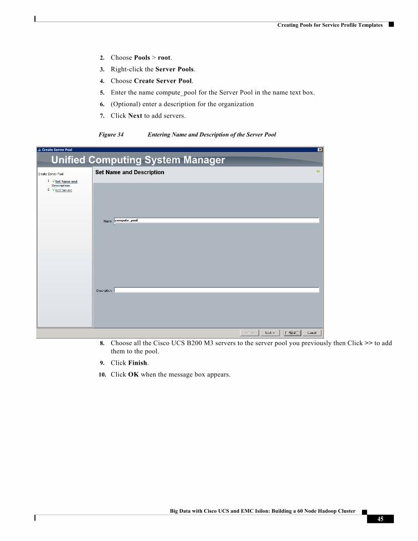
6. Choose LAN > VLANs.
7. Right-click the VLANs under the root organization.
8. Choose Create VLANs option to create the VLAN.
9. Enter vlan11_data for the VLAN Name.
10. Choose Common/Global for the vlan11_data.
11. Enter 11 in VLAN IDs field.
12. Click OK and then, click Finish.
13. Click OK in the success message box.
Figure 33 Creating VLAN to Communicate Between Compute Nodes and Isilon Cluster
Repeat the same steps for creating another VLAN called vlan12_compute and set the VLAN ID as 12.
Creating Server Pool
A server pool contains a set of servers. These servers typically share the same characteristics. Those characteristics can be their location in the chassis, or an attribute such as server type, amount of memory, local storage, type of CPU, or local drive configuration. You can manually assign a server to a server pool, or use server pool policies and server pool policy qualifications to automate the assignment
Follow these steps to configure the server pool within the Cisco UCS Manager GUI:
1. Choose the Servers tab in the left pane in the UCS Manager GUI.
44Big Data with Cisco UCS and EMC Isilon: Building a 60 Node Hadoop Cluster
Creating Pools for Service Profile Templates
2. Choose Pools > root.
3. Right-click the Server Pools.
4. Choose Create Server Pool.
5. Enter the name compute_pool for the Server Pool in the name text box.
6. (Optional) enter a description for the organization
7. Click Next to add servers.
Figure 34 Entering Name and Description of the Server Pool
8. Choose all the Cisco UCS B200 M3 servers to the server pool you previously then Click >> to add them to the pool.
9. Click Finish.
10. Click OK when the message box appears.
45Big Data with Cisco UCS and EMC Isilon: Building a 60 Node Hadoop Cluster
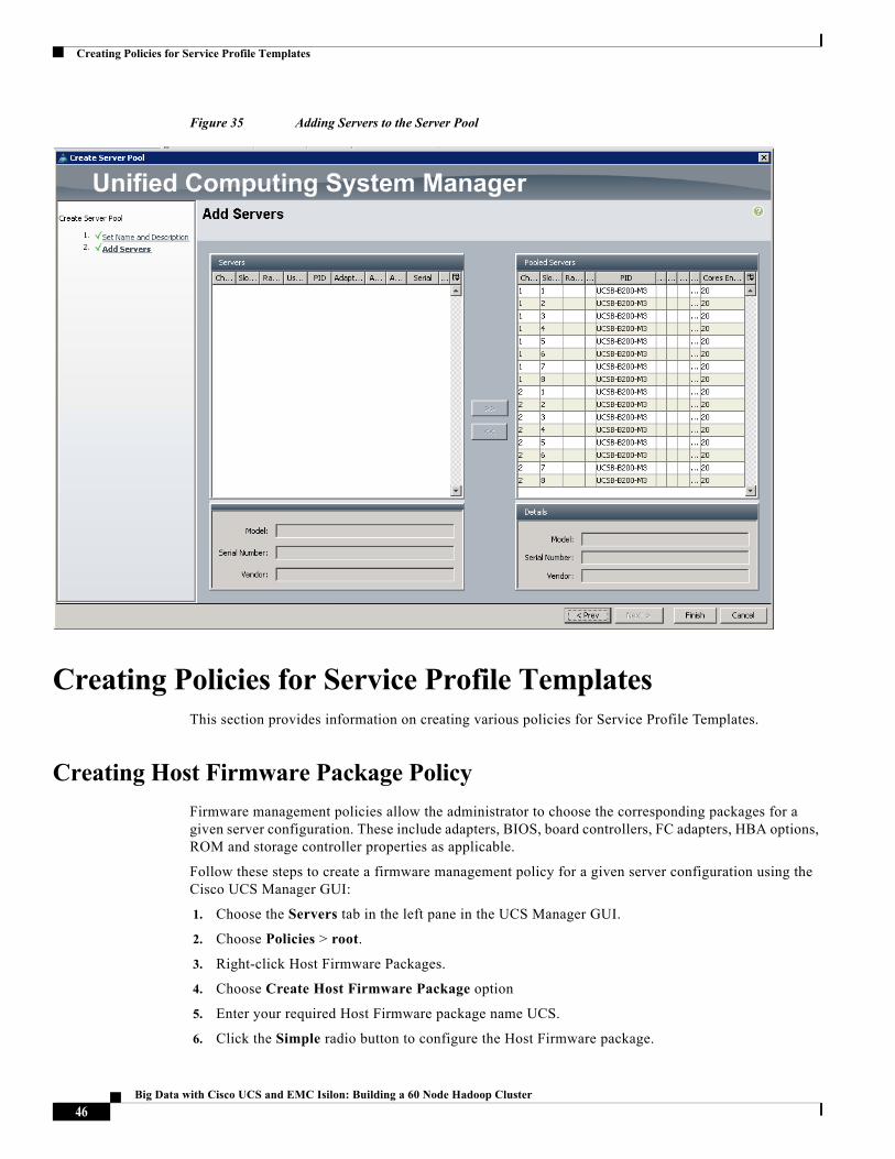
Creating Policies for Service Profile Templates
Figure 35 Adding Servers to the Server Pool
Creating Policies for Service Profile TemplatesThis section provides information on creating various policies for Service Profile Templates.
Creating Host Firmware Package Policy
Firmware management policies allow the administrator to choose the corresponding packages for a given server configuration. These include adapters, BIOS, board controllers, FC adapters, HBA options, ROM and storage controller properties as applicable.
Follow these steps to create a firmware management policy for a given server configuration using the Cisco UCS Manager GUI:
1. Choose the Servers tab in the left pane in the UCS Manager GUI.
2. Choose Policies > root.
3. Right-click Host Firmware Packages.
4. Choose Create Host Firmware Package option
5. Enter your required Host Firmware package name UCS.
6. Click the Simple radio button to configure the Host Firmware package.
46Big Data with Cisco UCS and EMC Isilon: Building a 60 Node Hadoop Cluster
Creating Policies for Service Profile Templates
7. Choose the appropriate Blade package that you have.
8. Click OK to complete creating the management firmware package.
9. Click OK.
Figure 36 Creating Host Firmware Package
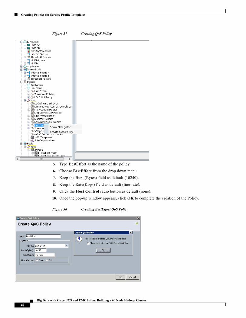
Creating QoS Policies
Follow these steps to create the QoS policy for a given server configuration using the Cisco
UCS Manager GUI:
Best Effort Policy
1. Choose the LAN tab in the left pane in the UCS Manager GUI.
2. Choose Policies > root.
3. Right-click QoS Policies.
4. Choose Create QoS Policy.
47Big Data with Cisco UCS and EMC Isilon: Building a 60 Node Hadoop Cluster
Creating Policies for Service Profile Templates
Figure 37 Creating QoS Policy
5. Type BestEffort as the name of the policy.
6. Choose BestEffort from the drop down menu.
7. Keep the Burst(Bytes) field as default (10240).
8. Keep the Rate(Kbps) field as default (line-rate).
9. Click the Host Control radio button as default (none).
10. Once the pop-up window appears, click OK to complete the creation of the Policy.
Figure 38 Creating BestEffort QoS Policy
48Big Data with Cisco UCS and EMC Isilon: Building a 60 Node Hadoop Cluster
Creating Policies for Service Profile Templates
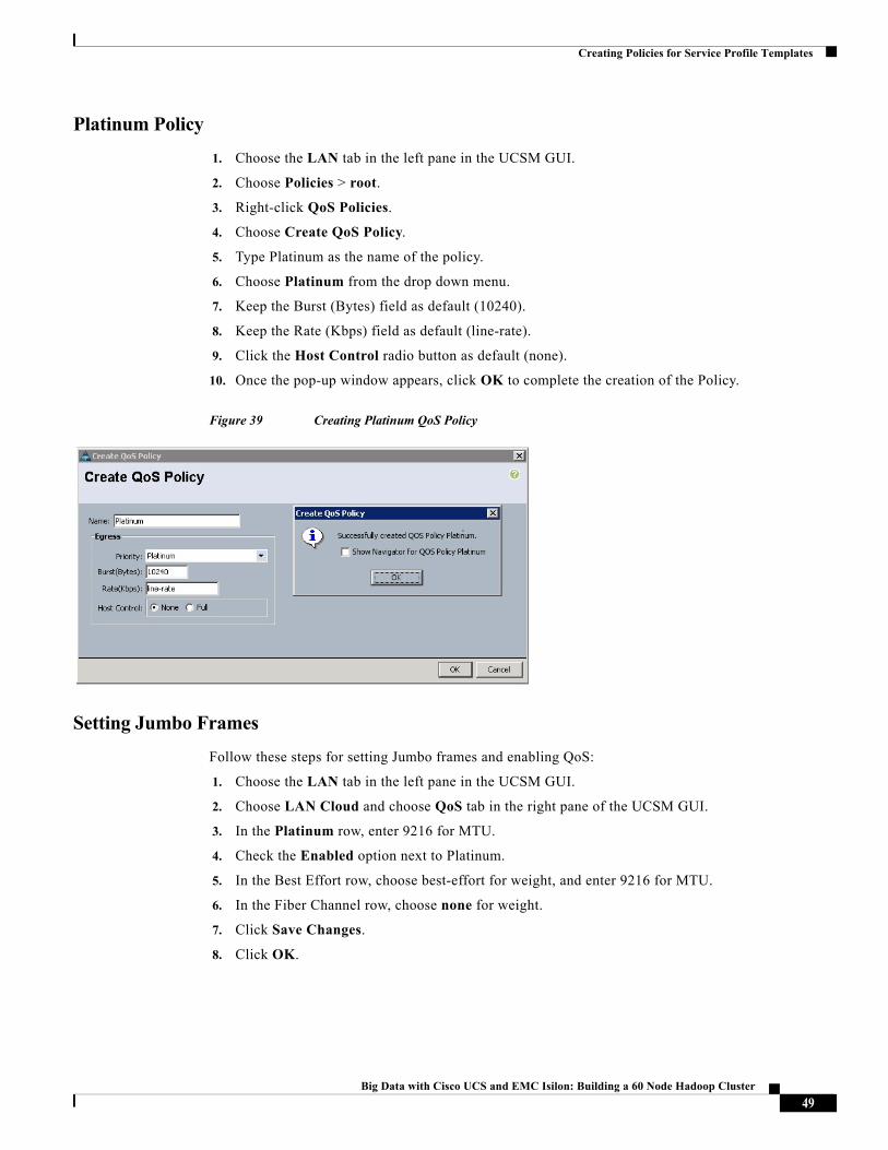
Platinum Policy
1. Choose the LAN tab in the left pane in the UCSM GUI.
2. Choose Policies > root.
3. Right-click QoS Policies.
4. Choose Create QoS Policy.
5. Type Platinum as the name of the policy.
6. Choose Platinum from the drop down menu.
7. Keep the Burst (Bytes) field as default (10240).
8. Keep the Rate (Kbps) field as default (line-rate).
9. Click the Host Control radio button as default (none).
10. Once the pop-up window appears, click OK to complete the creation of the Policy.
Figure 39 Creating Platinum QoS Policy
Setting Jumbo Frames
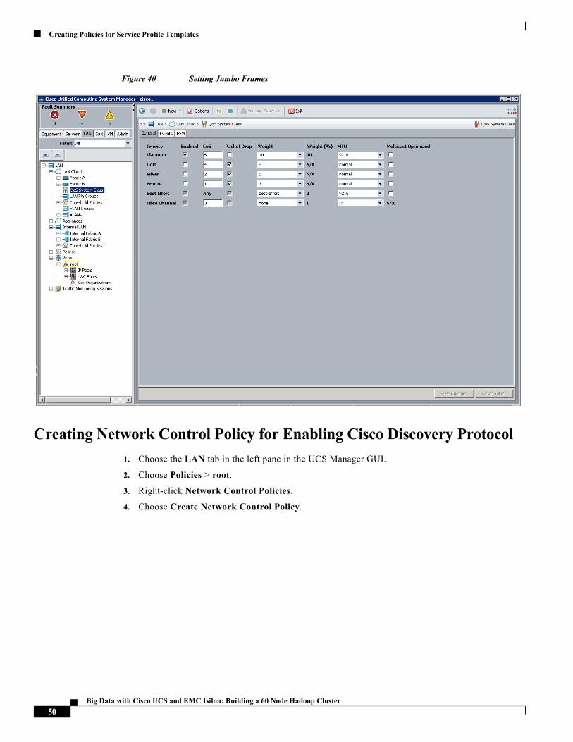
Follow these steps for setting Jumbo frames and enabling QoS:
1. Choose the LAN tab in the left pane in the UCSM GUI.
2. Choose LAN Cloud and choose QoS tab in the right pane of the UCSM GUI.
3. In the Platinum row, enter 9216 for MTU.
4. Check the Enabled option next to Platinum.
5. In the Best Effort row, choose best-effort for weight, and enter 9216 for MTU.
6. In the Fiber Channel row, choose none for weight.
7. Click Save Changes.
8. Click OK.
49Big Data with Cisco UCS and EMC Isilon: Building a 60 Node Hadoop Cluster
Creating Policies for Service Profile Templates
Figure 40 Setting Jumbo Frames
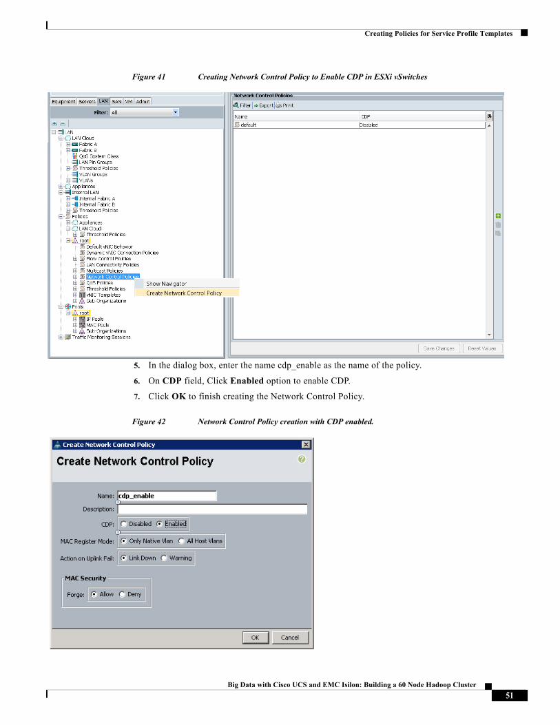
Creating Network Control Policy for Enabling Cisco Discovery Protocol
1. Choose the LAN tab in the left pane in the UCS Manager GUI.
2. Choose Policies > root.
3. Right-click Network Control Policies.
4. Choose Create Network Control Policy.
50Big Data with Cisco UCS and EMC Isilon: Building a 60 Node Hadoop Cluster
Creating Policies for Service Profile Templates
Figure 41 Creating Network Control Policy to Enable CDP in ESXi vSwitches
5. In the dialog box, enter the name cdp_enable as the name of the policy.
6. On CDP field, Click Enabled option to enable CDP.
7. Click OK to finish creating the Network Control Policy.
Figure 42 Network Control Policy creation with CDP enabled.
51Big Data with Cisco UCS and EMC Isilon: Building a 60 Node Hadoop Cluster
Creating Policies for Service Profile Templates
Creating Local Disk Configuration Policy
Follow these steps to create local disk configuration in the Cisco UCS Manager GUI:
1. Choose the Servers tab on the left pane in the UCS Manager GUI.
2. Go to Policies > root.
3. Right-click Local Disk Config Policies.
4. Choose Create Local Disk Configuration Policy.
5. Enter blade as the local disk configuration policy name.
6. Change the Mode to RAID 1 Mirrored. Uncheck the Protect Configuration box.
7. Keep the FlexFlash State field as default (Disable).
8. Keep the FlexFlash RAID Reporting State field as default (Disable).
9. Click OK to complete the creation of the Local Disk Configuration Policy.
10. Click OK.
Figure 43 Configuring Local Disk Policy
52Big Data with Cisco UCS and EMC Isilon: Building a 60 Node Hadoop Cluster
Creating Policies for Service Profile Templates
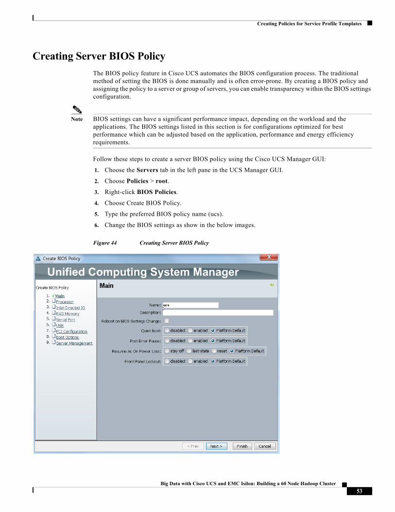
Creating Server BIOS Policy
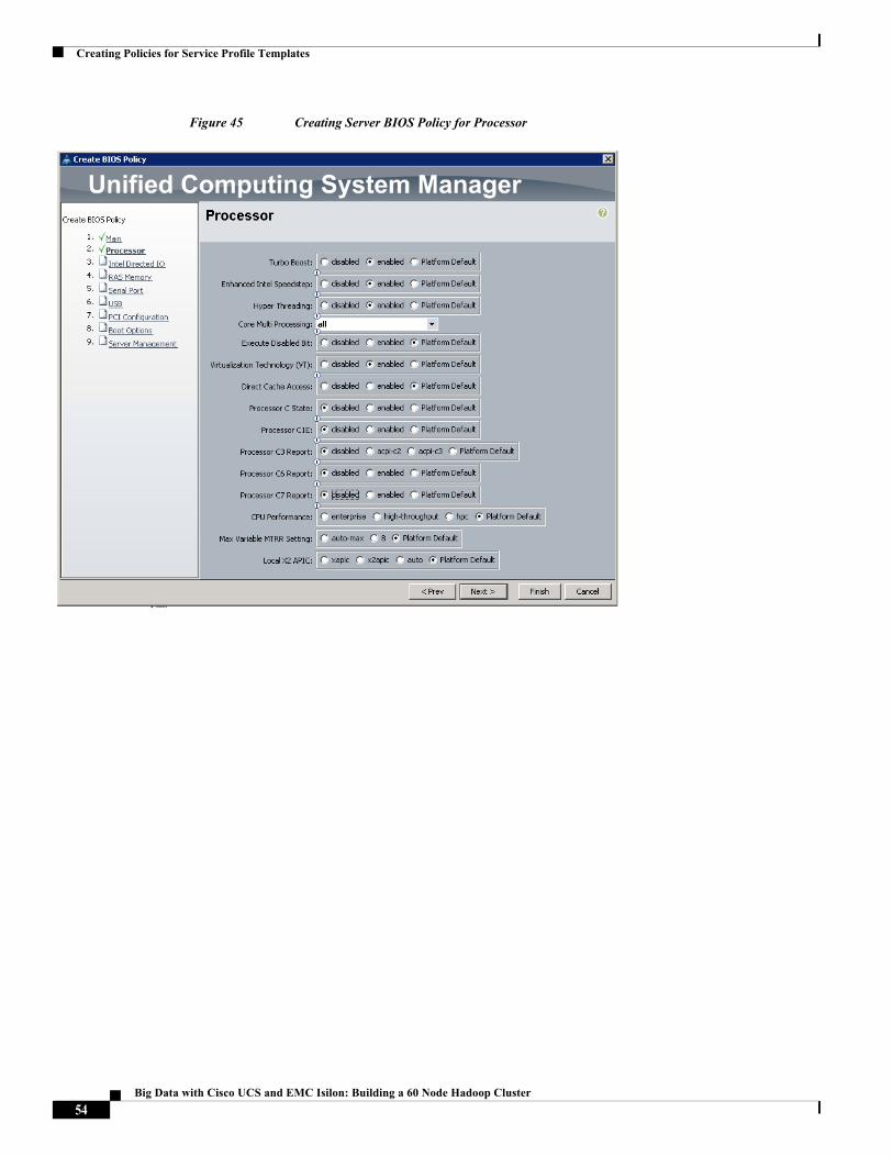
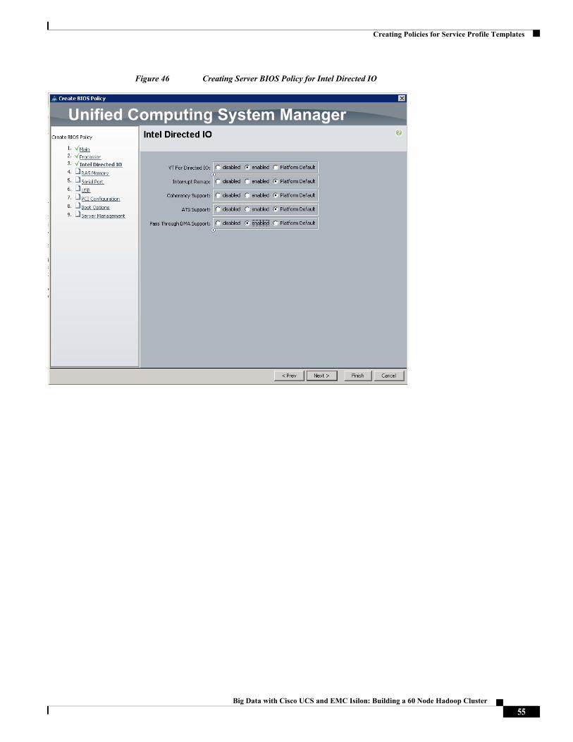
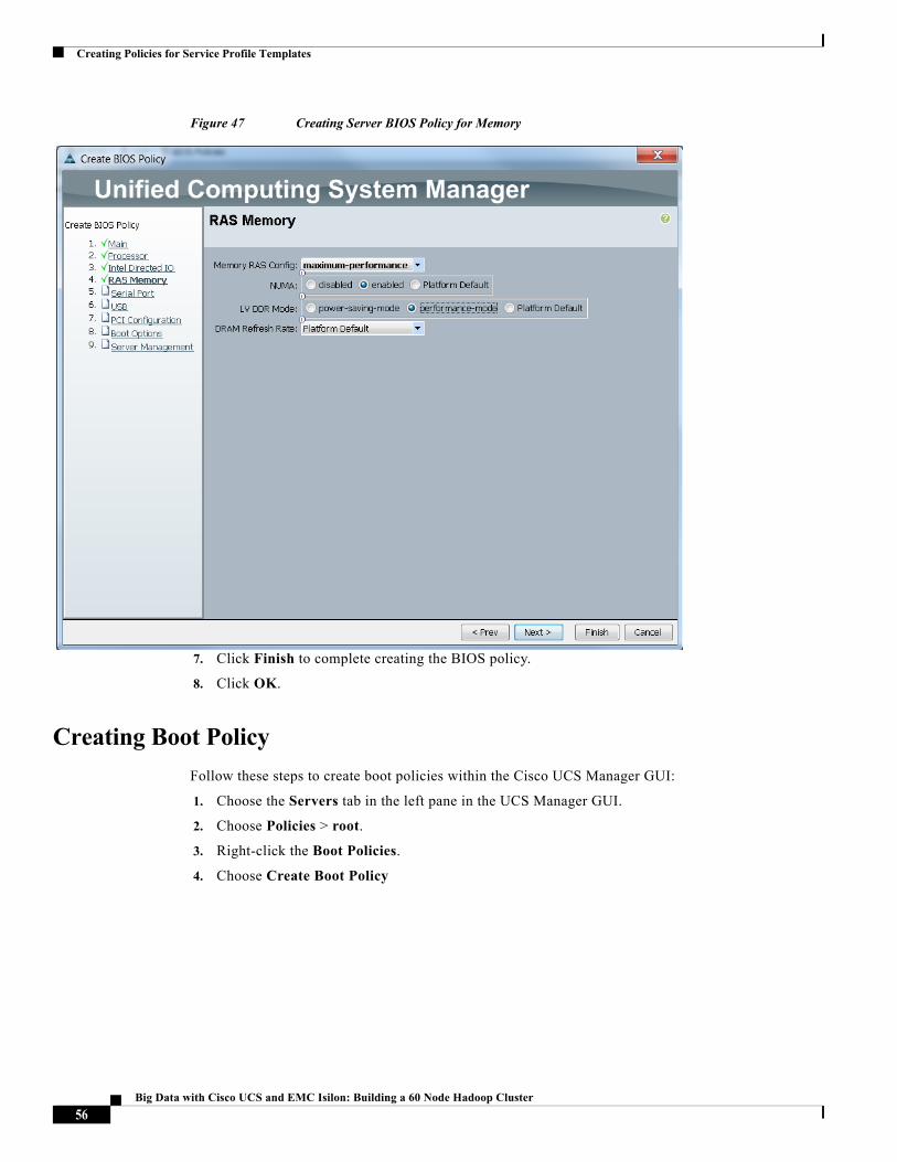
The BIOS policy feature in Cisco UCS automates the BIOS configuration process. The traditional method of setting the BIOS is done manually and is often error-prone. By creating a BIOS policy and assigning the policy to a server or group of servers, you can enable transparency within the BIOS settings configuration.
Note BIOS settings can have a significant performance impact, depending on the workload and the applications. The BIOS settings listed in this section is for configurations optimized for best performance which can be adjusted based on the application, performance and energy efficiency requirements.
Follow these steps to create a server BIOS policy using the Cisco UCS Manager GUI:
1. Choose the Servers tab in the left pane in the UCS Manager GUI.
2. Choose Policies > root.
3. Right-click BIOS Policies.
4. Choose Create BIOS Policy.
5. Type the preferred BIOS policy name (ucs).
6. Change the BIOS settings as show in the below images.
Figure 44 Creating Server BIOS Policy
53Big Data with Cisco UCS and EMC Isilon: Building a 60 Node Hadoop Cluster
Creating Policies for Service Profile Templates
Figure 45 Creating Server BIOS Policy for Processor
54Big Data with Cisco UCS and EMC Isilon: Building a 60 Node Hadoop Cluster
Creating Policies for Service Profile Templates
Figure 46 Creating Server BIOS Policy for Intel Directed IO
55Big Data with Cisco UCS and EMC Isilon: Building a 60 Node Hadoop Cluster
Creating Policies for Service Profile Templates
Figure 47 Creating Server BIOS Policy for Memory
7. Click Finish to complete creating the BIOS policy.
8. Click OK.
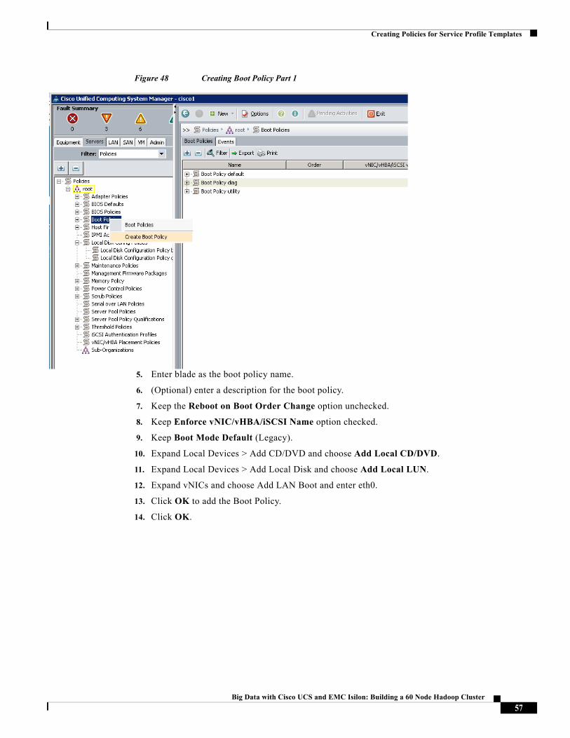
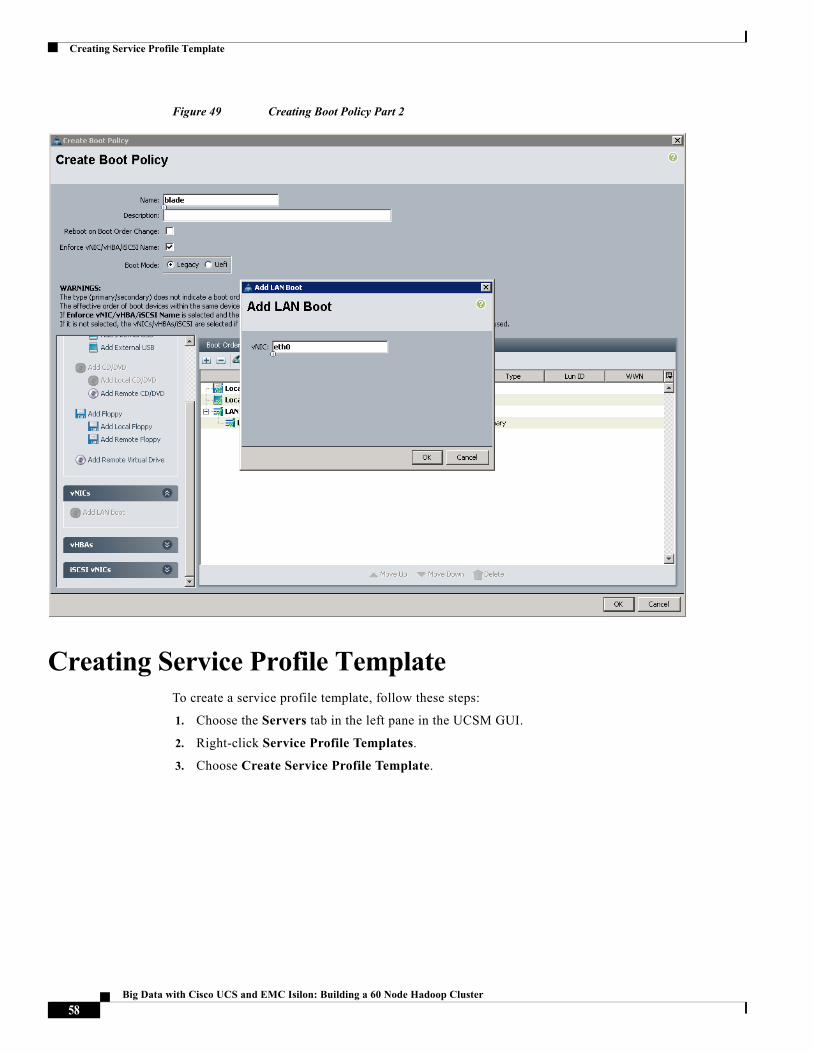
Creating Boot Policy
Follow these steps to create boot policies within the Cisco UCS Manager GUI:
1. Choose the Servers tab in the left pane in the UCS Manager GUI.
2. Choose Policies > root.
3. Right-click the Boot Policies.
4. Choose Create Boot Policy
56Big Data with Cisco UCS and EMC Isilon: Building a 60 Node Hadoop Cluster
Creating Policies for Service Profile Templates
Figure 48 Creating Boot Policy Part 1
5. Enter blade as the boot policy name.
6. (Optional) enter a description for the boot policy.
7. Keep the Reboot on Boot Order Change option unchecked.
8. Keep Enforce vNIC/vHBA/iSCSI Name option checked.
9. Keep Boot Mode Default (Legacy).
10. Expand Local Devices > Add CD/DVD and choose Add Local CD/DVD.
11. Expand Local Devices > Add Local Disk and choose Add Local LUN.
12. Expand vNICs and choose Add LAN Boot and enter eth0.
13. Click OK to add the Boot Policy.
14. Click OK.
57Big Data with Cisco UCS and EMC Isilon: Building a 60 Node Hadoop Cluster
Creating Service Profile Template
Figure 49 Creating Boot Policy Part 2
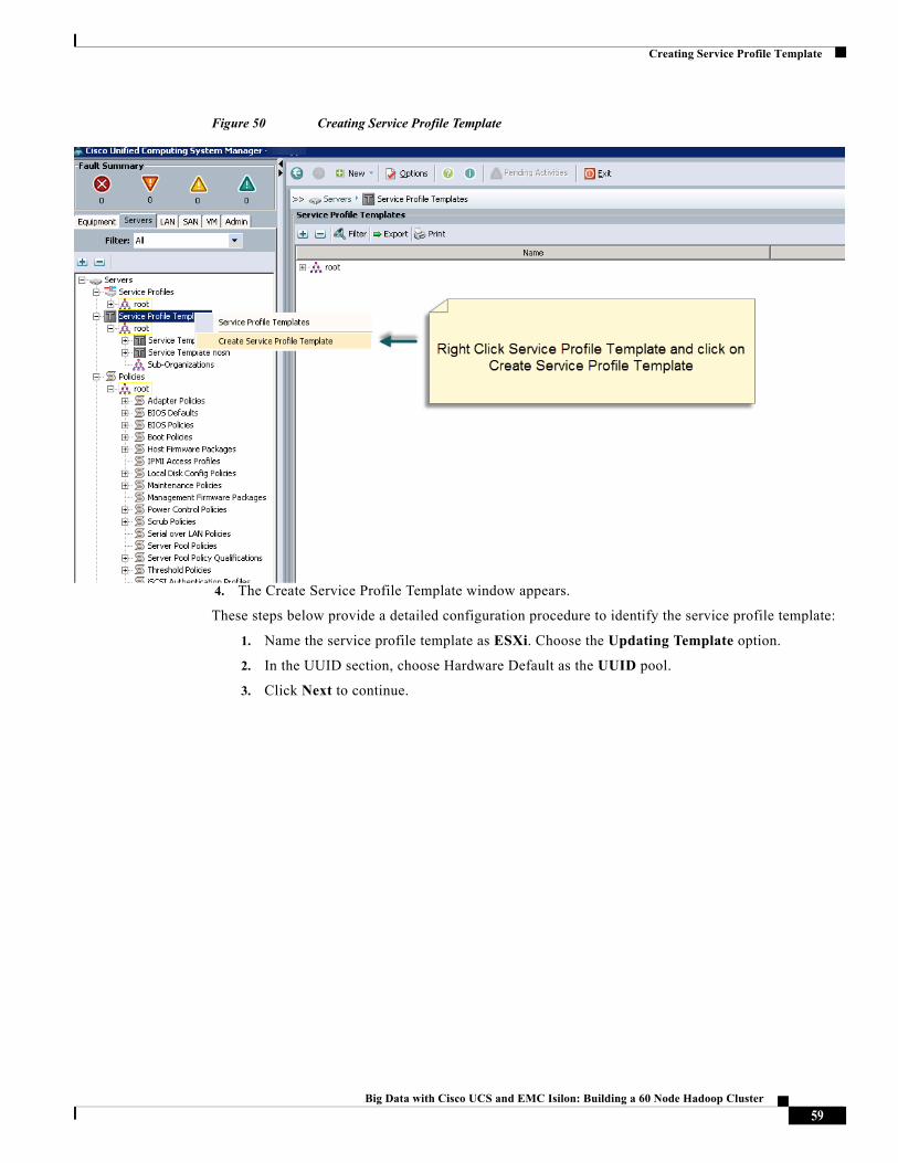
Creating Service Profile TemplateTo create a service profile template, follow these steps:
1. Choose the Servers tab in the left pane in the UCSM GUI.
2. Right-click Service Profile Templates.
3. Choose Create Service Profile Template.
58Big Data with Cisco UCS and EMC Isilon: Building a 60 Node Hadoop Cluster
Creating Service Profile Template
Figure 50 Creating Service Profile Template
4. The Create Service Profile Template window appears.
These steps below provide a detailed configuration procedure to identify the service profile template:
1. Name the service profile template as ESXi. Choose the Updating Template option.
2. In the UUID section, choose Hardware Default as the UUID pool.
3. Click Next to continue.
59Big Data with Cisco UCS and EMC Isilon: Building a 60 Node Hadoop Cluster
Creating Service Profile Template
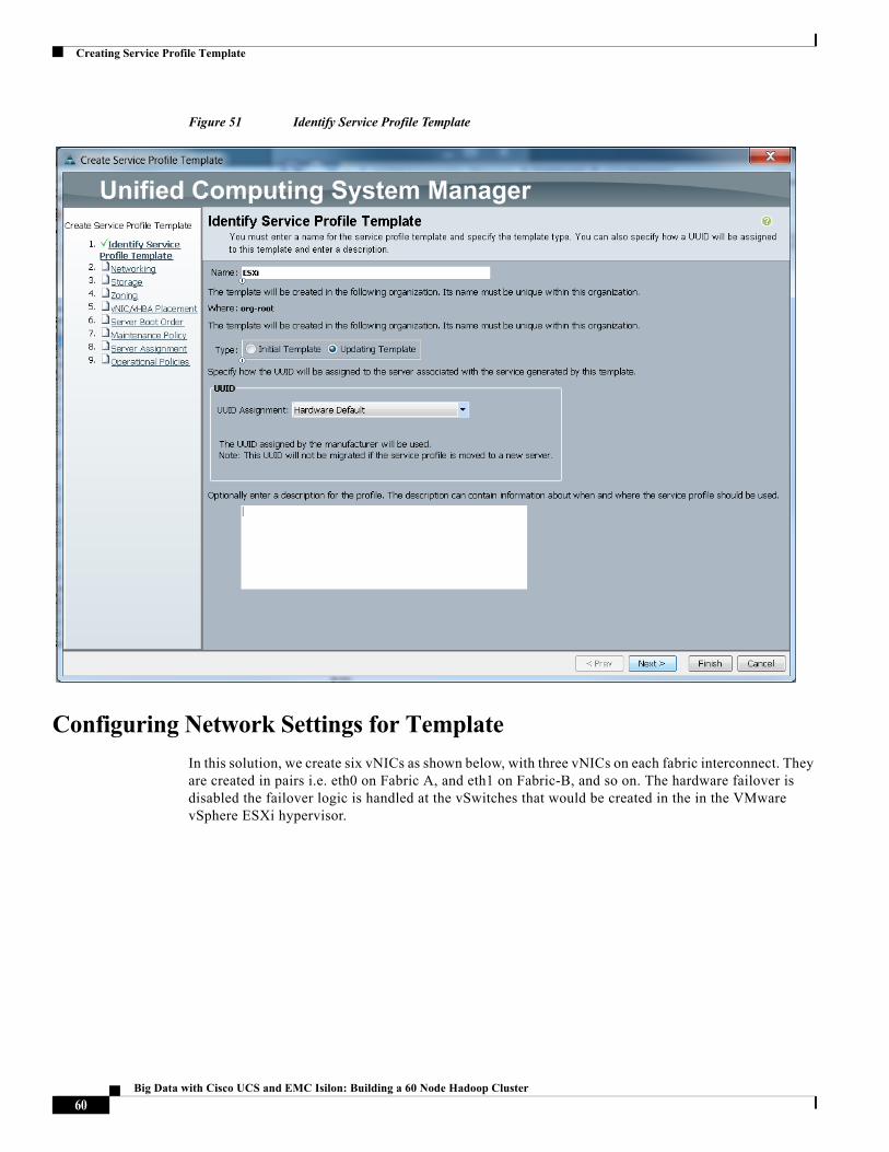
Figure 51 Identify Service Profile Template
Configuring Network Settings for Template
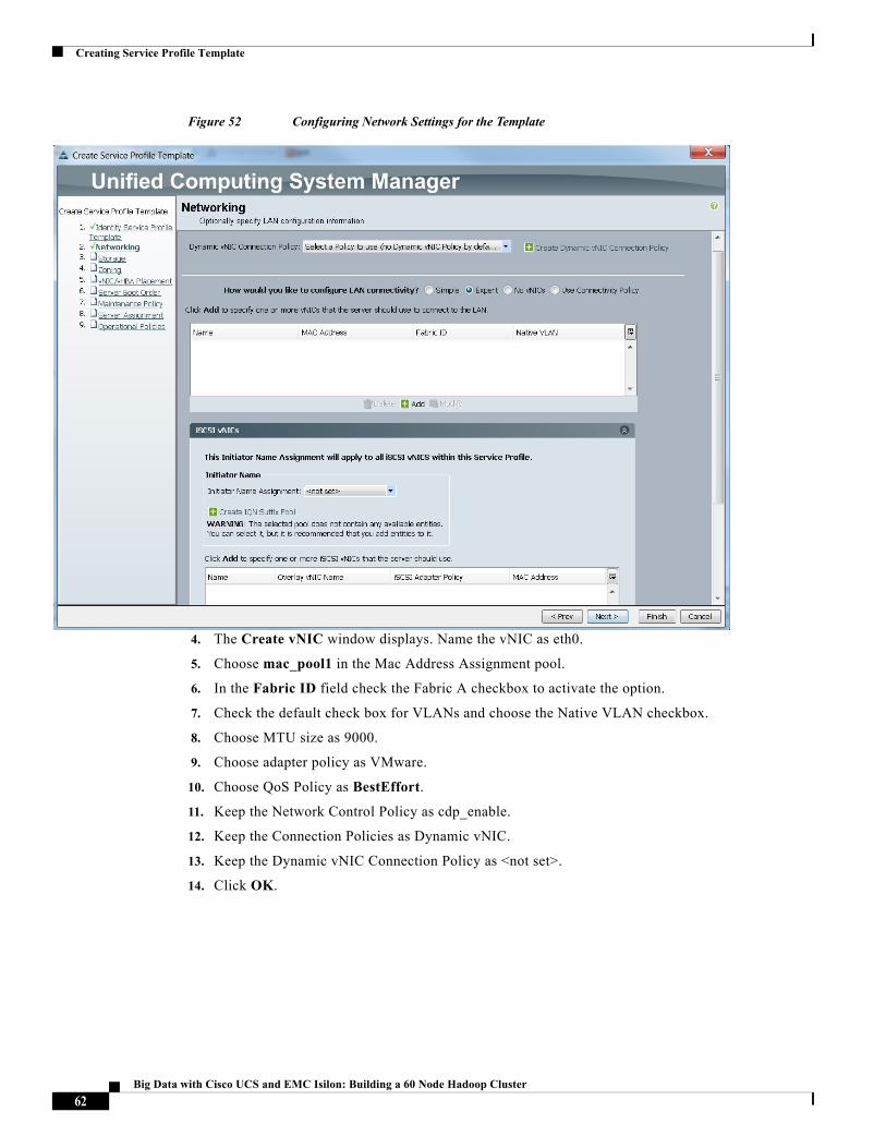
In this solution, we create six vNICs as shown below, with three vNICs on each fabric interconnect. They are created in pairs i.e. eth0 on Fabric A, and eth1 on Fabric-B, and so on. The hardware failover is disabled the failover logic is handled at the vSwitches that would be created in the in the VMware vSphere ESXi hypervisor.
60Big Data with Cisco UCS and EMC Isilon: Building a 60 Node Hadoop Cluster
Creating Service Profile Template
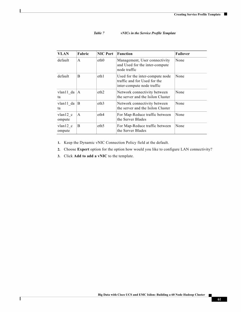
Table 7 vNICs in the Service Profile Template
1. Keep the Dynamic vNIC Connection Policy field at the default.
2. Choose Expert option for the option how would you like to configure LAN connectivity?
3. Click Add to add a vNIC to the template.
VLAN Fabric NIC Port Function Failover
default A eth0 Management, User connectivity and Used for the inter-compute node traffic
None
default B eth1 Used for the inter-compute node traffic and for Used for the inter-compute node traffic
None
vlan11_data
A eth2 Network connectivity between the server and the Isilon Cluster
None
vlan11_data
B eth3 Network connectivity between the server and the Isilon Cluster
None
vlan12_compute
A eth4 For Map-Reduce traffic between the Server Blades
None
vlan12_compute
B eth5 For Map-Reduce traffic between the Server Blades
None
61Big Data with Cisco UCS and EMC Isilon: Building a 60 Node Hadoop Cluster
Creating Service Profile Template
Figure 52 Configuring Network Settings for the Template
4. The Create vNIC window displays. Name the vNIC as eth0.
5. Choose mac_pool1 in the Mac Address Assignment pool.
6. In the Fabric ID field check the Fabric A checkbox to activate the option.
7. Check the default check box for VLANs and choose the Native VLAN checkbox.
8. Choose MTU size as 9000.
9. Choose adapter policy as VMware.
10. Choose QoS Policy as BestEffort.
11. Keep the Network Control Policy as cdp_enable.
12. Keep the Connection Policies as Dynamic vNIC.
13. Keep the Dynamic vNIC Connection Policy as <not set>.
14. Click OK.
62Big Data with Cisco UCS and EMC Isilon: Building a 60 Node Hadoop Cluster
Creating Service Profile Template
Figure 53 Configuring vNIC eth0 For Management Traffic on Default VLAN (Fabric A)
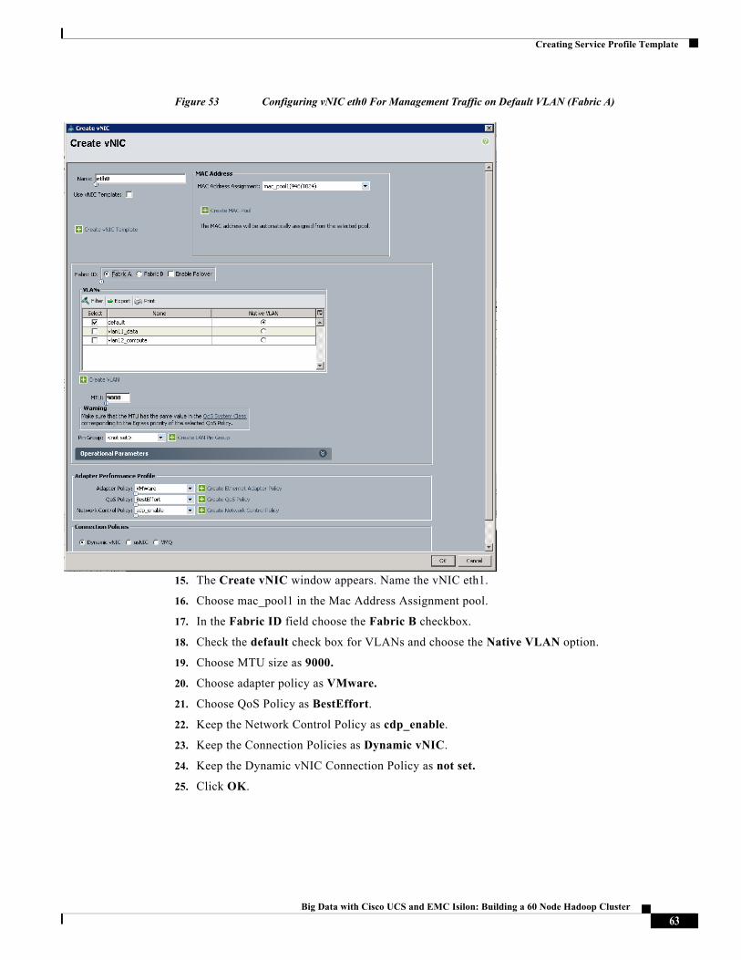
15. The Create vNIC window appears. Name the vNIC eth1.
16. Choose mac_pool1 in the Mac Address Assignment pool.
17. In the Fabric ID field choose the Fabric B checkbox.
18. Check the default check box for VLANs and choose the Native VLAN option.
19. Choose MTU size as 9000.
20. Choose adapter policy as VMware.
21. Choose QoS Policy as BestEffort.
22. Keep the Network Control Policy as cdp_enable.
23. Keep the Connection Policies as Dynamic vNIC.
24. Keep the Dynamic vNIC Connection Policy as not set.
25. Click OK.
63Big Data with Cisco UCS and EMC Isilon: Building a 60 Node Hadoop Cluster
Creating Service Profile Template
Figure 54 Configuring vNIC eth1 For Management Traffic on Default VLAN (Fabric B)
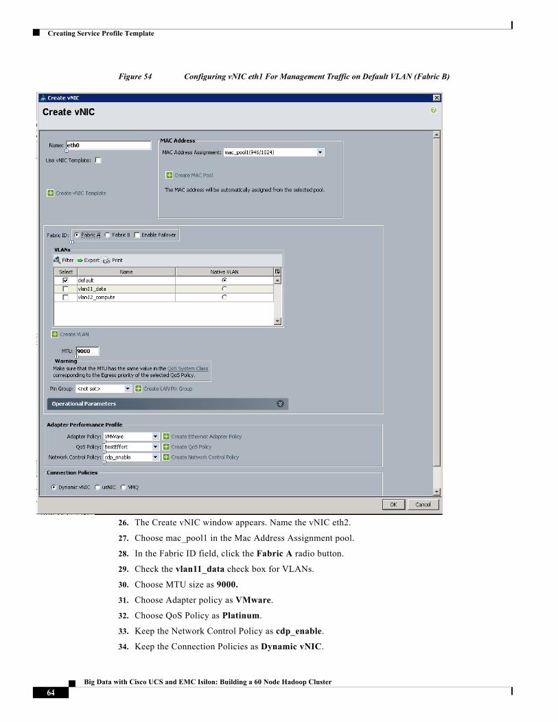
26. The Create vNIC window appears. Name the vNIC eth2.
27. Choose mac_pool1 in the Mac Address Assignment pool.
28. In the Fabric ID field, click the Fabric A radio button.
29. Check the vlan11_data check box for VLANs.
30. Choose MTU size as 9000.
31. Choose Adapter policy as VMware.
32. Choose QoS Policy as Platinum.
33. Keep the Network Control Policy as cdp_enable.
34. Keep the Connection Policies as Dynamic vNIC.
64Big Data with Cisco UCS and EMC Isilon: Building a 60 Node Hadoop Cluster
Creating Service Profile Template
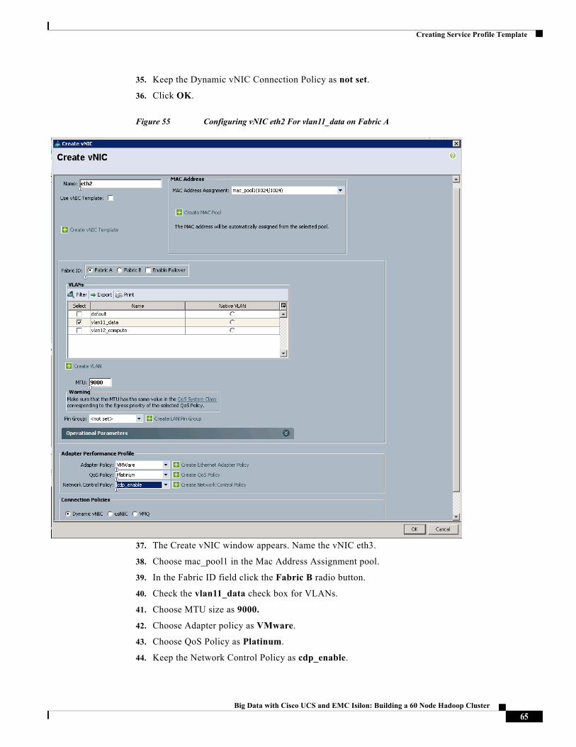
35. Keep the Dynamic vNIC Connection Policy as not set.
36. Click OK.
Figure 55 Configuring vNIC eth2 For vlan11_data on Fabric A
37. The Create vNIC window appears. Name the vNIC eth3.
38. Choose mac_pool1 in the Mac Address Assignment pool.
39. In the Fabric ID field click the Fabric B radio button.
40. Check the vlan11_data check box for VLANs.
41. Choose MTU size as 9000.
42. Choose Adapter policy as VMware.
43. Choose QoS Policy as Platinum.
44. Keep the Network Control Policy as cdp_enable.
65Big Data with Cisco UCS and EMC Isilon: Building a 60 Node Hadoop Cluster
Creating Service Profile Template
45. Keep the Connection Policies as Dynamic vNIC.
46. Keep the Dynamic vNIC Connection Policy as not set.
47. Click OK.
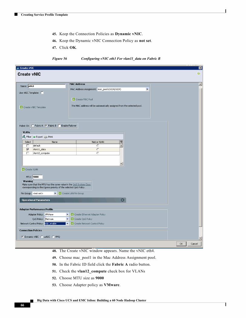
Figure 56 Configuring vNIC eth3 For vlan11_data on Fabric B
48. The Create vNIC window appears. Name the vNIC eth4.
49. Choose mac_pool1 in the Mac Address Assignment pool.
50. In the Fabric ID field click the Fabric A radio button.
51. Check the vlan12_compute check box for VLANs
52. Choose MTU size as 9000
53. Choose Adapter policy as VMware.
66Big Data with Cisco UCS and EMC Isilon: Building a 60 Node Hadoop Cluster
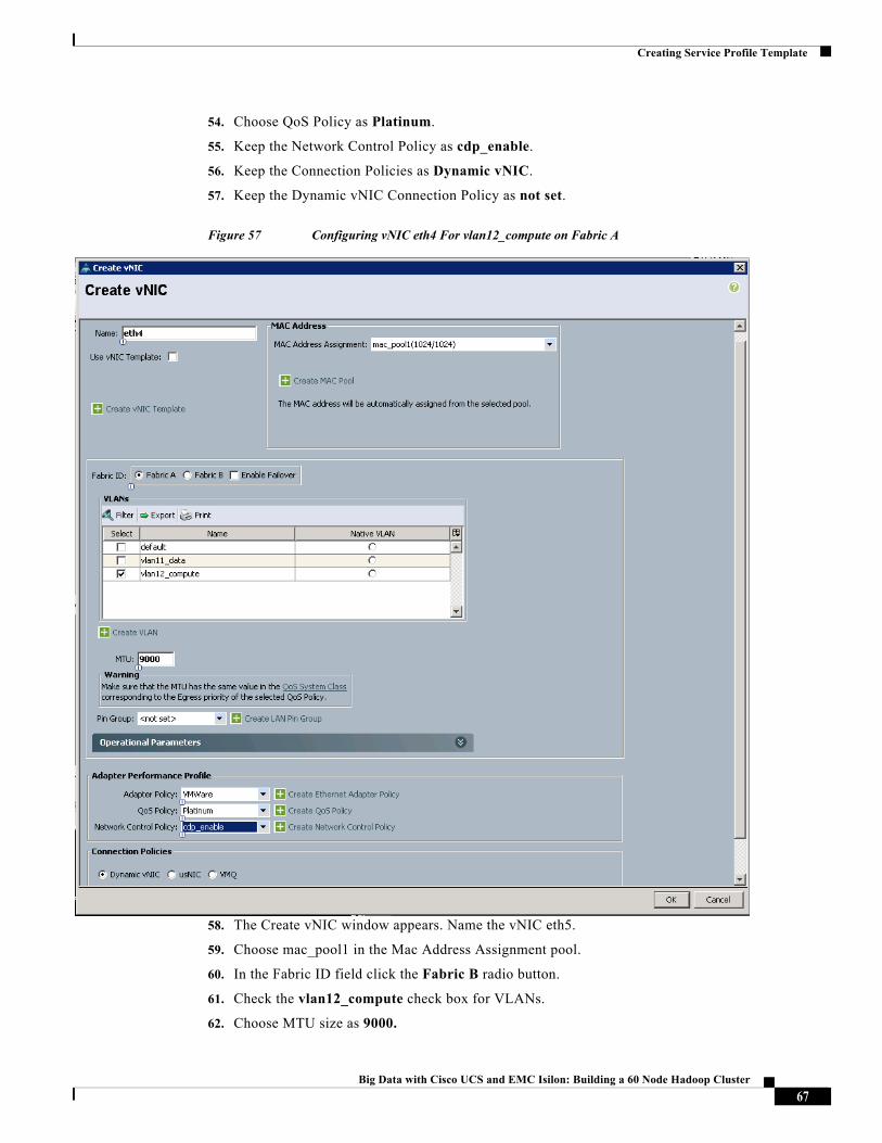
Creating Service Profile Template
54. Choose QoS Policy as Platinum.
55. Keep the Network Control Policy as cdp_enable.
56. Keep the Connection Policies as Dynamic vNIC.
57. Keep the Dynamic vNIC Connection Policy as not set.
Figure 57 Configuring vNIC eth4 For vlan12_compute on Fabric A
58. The Create vNIC window appears. Name the vNIC eth5.
59. Choose mac_pool1 in the Mac Address Assignment pool.
60. In the Fabric ID field click the Fabric B radio button.
61. Check the vlan12_compute check box for VLANs.
62. Choose MTU size as 9000.
67Big Data with Cisco UCS and EMC Isilon: Building a 60 Node Hadoop Cluster
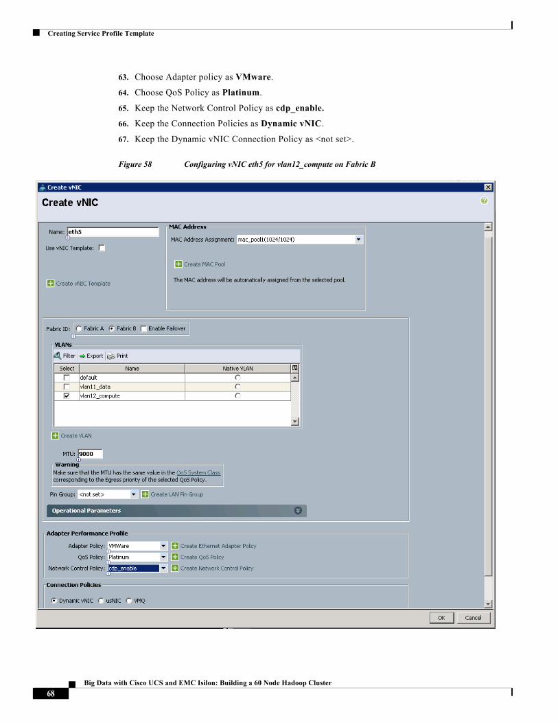
Creating Service Profile Template
63. Choose Adapter policy as VMware.
64. Choose QoS Policy as Platinum.
65. Keep the Network Control Policy as cdp_enable.
66. Keep the Connection Policies as Dynamic vNIC.
67. Keep the Dynamic vNIC Connection Policy as <not set>.
Figure 58 Configuring vNIC eth5 for vlan12_compute on Fabric B
68Big Data with Cisco UCS and EMC Isilon: Building a 60 Node Hadoop Cluster
Creating Service Profile Template
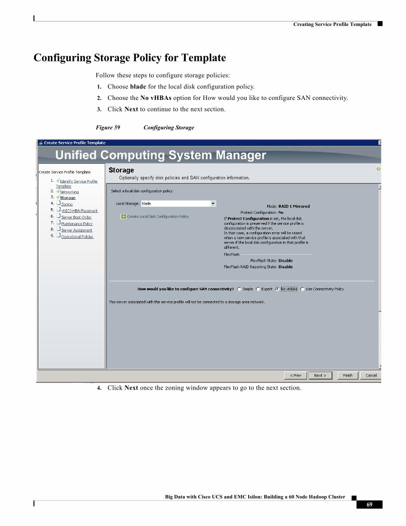
Configuring Storage Policy for Template
Follow these steps to configure storage policies:
1. Choose blade for the local disk configuration policy.
2. Choose the No vHBAs option for How would you like to configure SAN connectivity.
3. Click Next to continue to the next section.
Figure 59 Configuring Storage
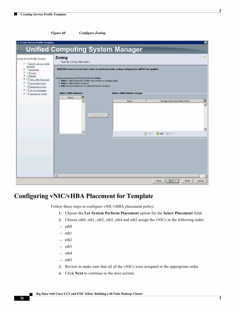
4. Click Next once the zoning window appears to go to the next section.
69Big Data with Cisco UCS and EMC Isilon: Building a 60 Node Hadoop Cluster
Creating Service Profile Template
Figure 60 Configure Zoning
Configuring vNIC/vHBA Placement for Template
Follow these steps to configure vNIC/vHBA placement policy:
1. Choose the Let System Perform Placement option for the Select Placement field.
2. Choose eth0, eth1, eth2, eth3, eth4 and eth5 assign the vNICs in the following order:
– eth0
– eth1
– eth2
– eth3
– eth4
– eth5
3. Review to make sure that all of the vNICs were assigned in the appropriate order.
4. Click Next to continue to the next section.
70Big Data with Cisco UCS and EMC Isilon: Building a 60 Node Hadoop Cluster
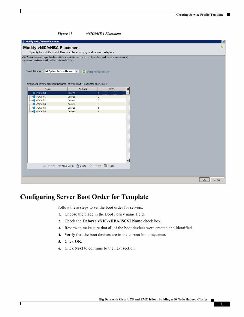
Creating Service Profile Template
Figure 61 vNIC/vHBA Placement
Configuring Server Boot Order for Template
Follow these steps to set the boot order for servers:
1. Choose the blade in the Boot Policy name field.
2. Check the Enforce vNIC/vHBA/iSCSI Name check box.
3. Review to make sure that all of the boot devices were created and identified.
4. Verify that the boot devices are in the correct boot sequence.
5. Click OK.
6. Click Next to continue to the next section.
71Big Data with Cisco UCS and EMC Isilon: Building a 60 Node Hadoop Cluster
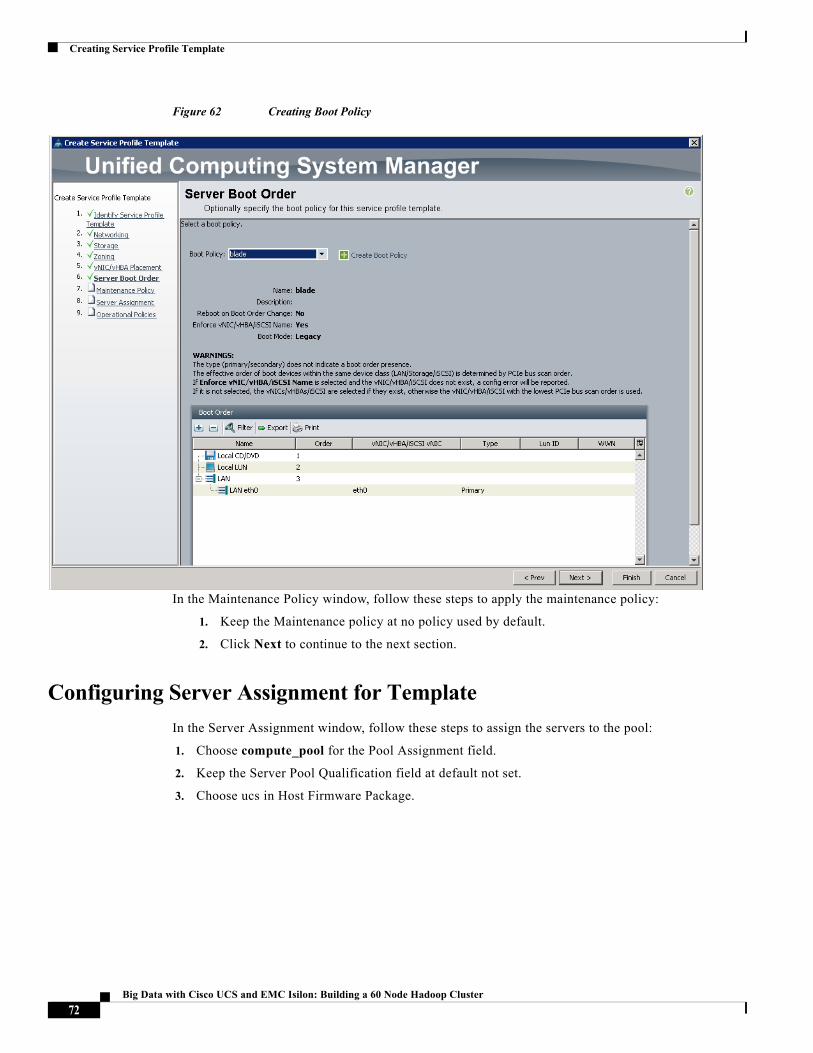
Creating Service Profile Template
Figure 62 Creating Boot Policy
In the Maintenance Policy window, follow these steps to apply the maintenance policy:
1. Keep the Maintenance policy at no policy used by default.
2. Click Next to continue to the next section.
Configuring Server Assignment for Template
In the Server Assignment window, follow these steps to assign the servers to the pool:
1. Choose compute_pool for the Pool Assignment field.
2. Keep the Server Pool Qualification field at default not set.
3. Choose ucs in Host Firmware Package.
72Big Data with Cisco UCS and EMC Isilon: Building a 60 Node Hadoop Cluster
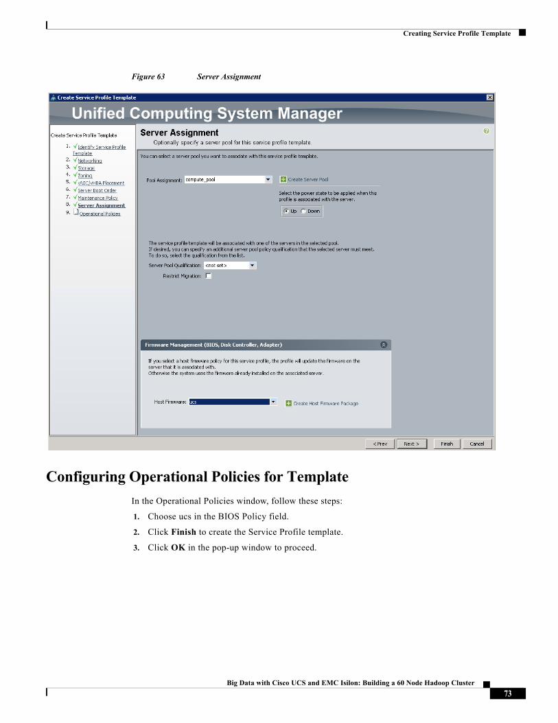
Creating Service Profile Template
Figure 63 Server Assignment
Configuring Operational Policies for Template
In the Operational Policies window, follow these steps:
1. Choose ucs in the BIOS Policy field.
2. Click Finish to create the Service Profile template.
3. Click OK in the pop-up window to proceed.
73Big Data with Cisco UCS and EMC Isilon: Building a 60 Node Hadoop Cluster
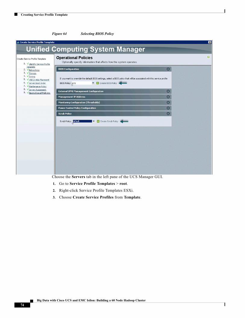
Creating Service Profile Template
Figure 64 Selecting BIOS Policy
Choose the Servers tab in the left pane of the UCS Manager GUI.
1. Go to Service Profile Templates > root.
2. Right-click Service Profile Templates ESXi.
3. Choose Create Service Profiles from Template.
74Big Data with Cisco UCS and EMC Isilon: Building a 60 Node Hadoop Cluster
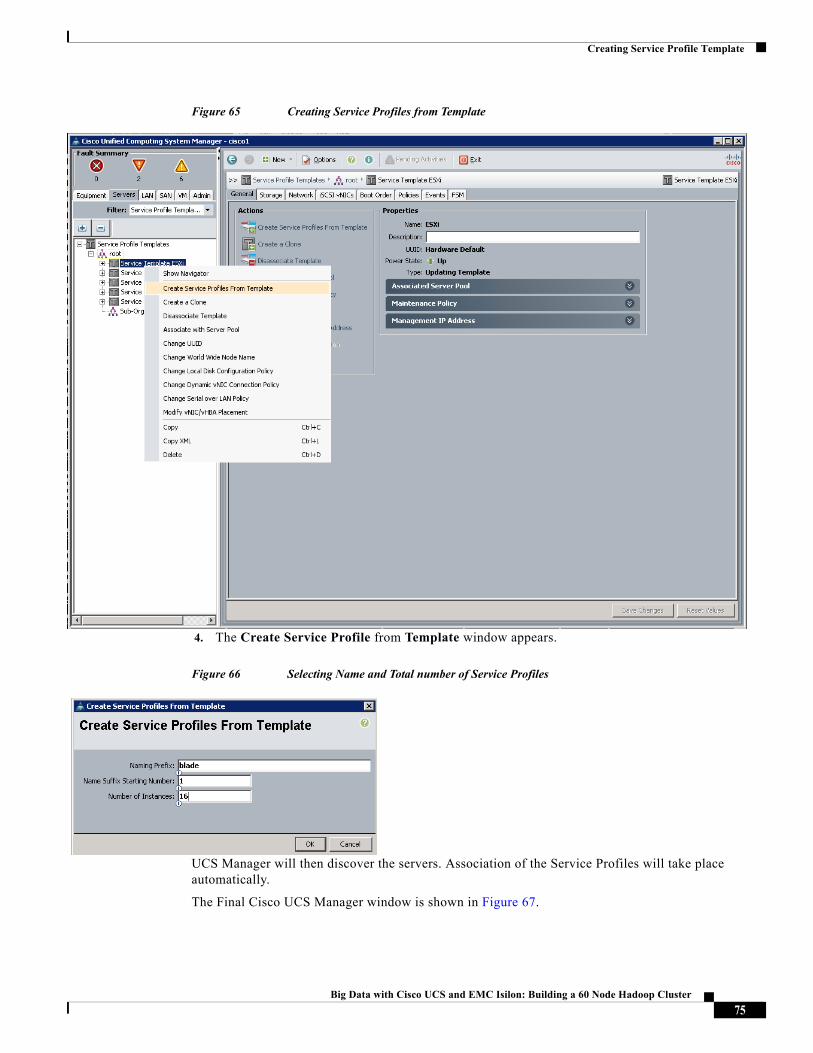
Creating Service Profile Template
Figure 65 Creating Service Profiles from Template
4. The Create Service Profile from Template window appears.
Figure 66 Selecting Name and Total number of Service Profiles
UCS Manager will then discover the servers. Association of the Service Profiles will take place automatically.
The Final Cisco UCS Manager window is shown in Figure 67.
75Big Data with Cisco UCS and EMC Isilon: Building a 60 Node Hadoop Cluster
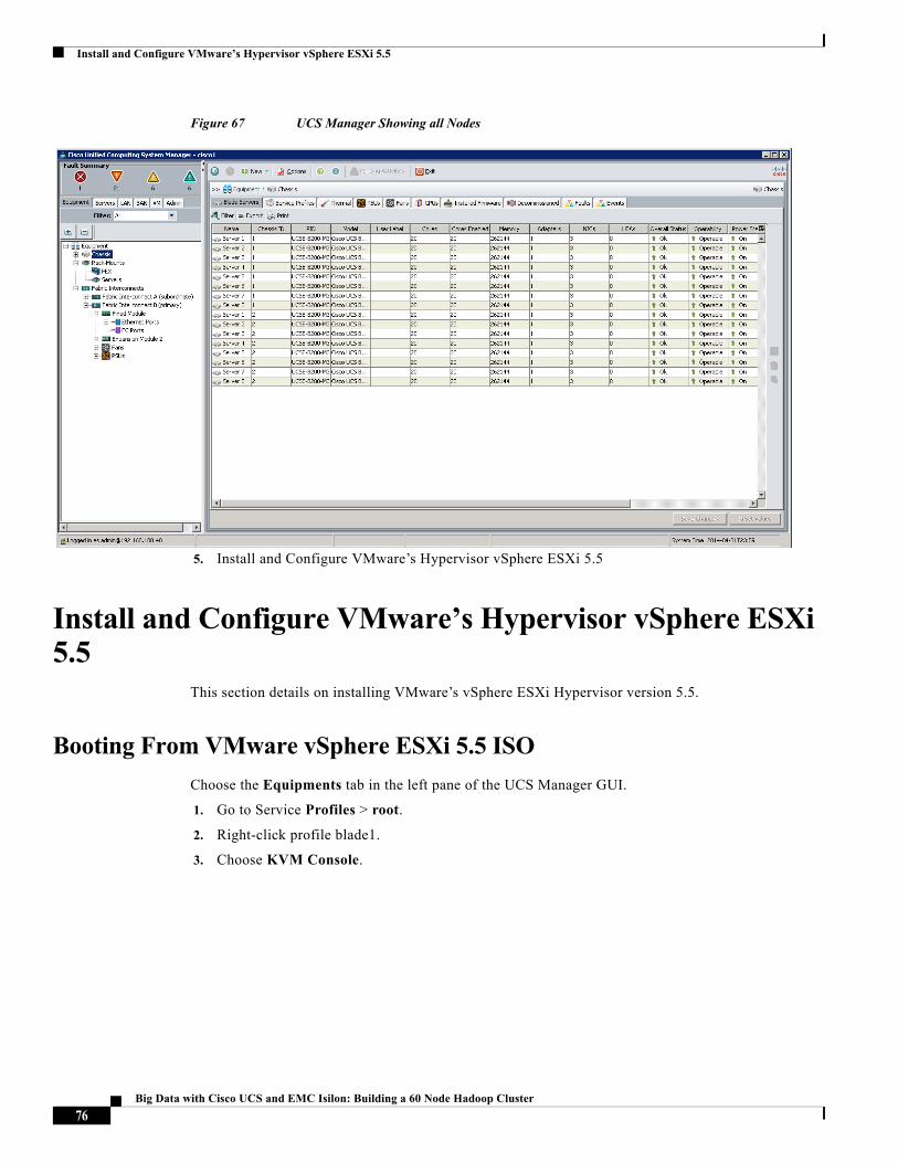
Install and Configure VMware’s Hypervisor vSphere ESXi 5.5
Figure 67 UCS Manager Showing all Nodes
5. Install and Configure VMware’s Hypervisor vSphere ESXi 5.5
Install and Configure VMware’s Hypervisor vSphere ESXi 5.5
This section details on installing VMware’s vSphere ESXi Hypervisor version 5.5.
Booting From VMware vSphere ESXi 5.5 ISO
Choose the Equipments tab in the left pane of the UCS Manager GUI.
1. Go to Service Profiles > root.
2. Right-click profile blade1.
3. Choose KVM Console.
76Big Data with Cisco UCS and EMC Isilon: Building a 60 Node Hadoop Cluster
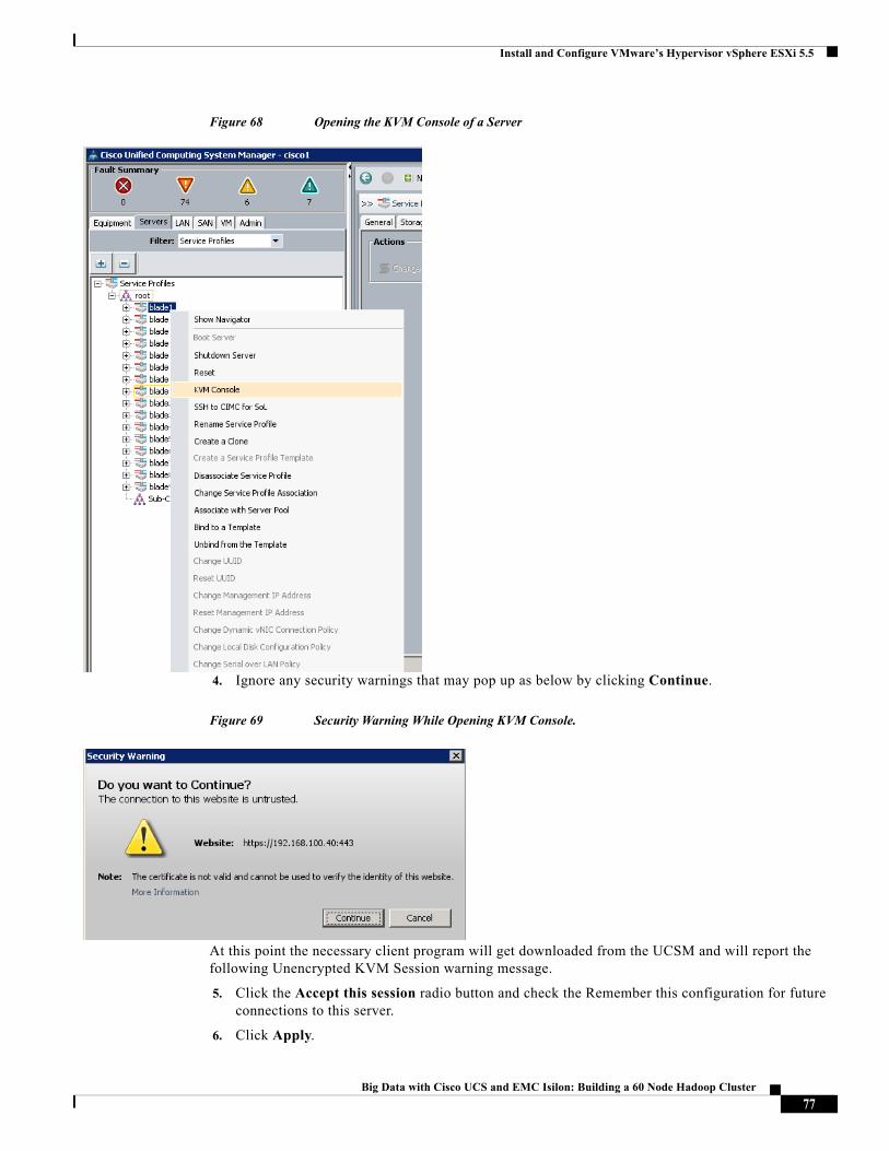
Install and Configure VMware’s Hypervisor vSphere ESXi 5.5
Figure 68 Opening the KVM Console of a Server
4. Ignore any security warnings that may pop up as below by clicking Continue.
Figure 69 Security Warning While Opening KVM Console.
At this point the necessary client program will get downloaded from the UCSM and will report the following Unencrypted KVM Session warning message.
5. Click the Accept this session radio button and check the Remember this configuration for future connections to this server.
6. Click Apply.
77Big Data with Cisco UCS and EMC Isilon: Building a 60 Node Hadoop Cluster
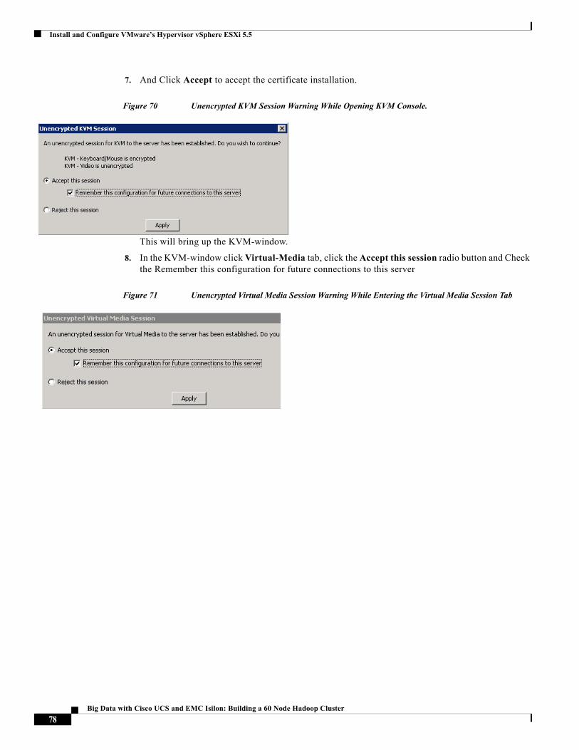
Install and Configure VMware’s Hypervisor vSphere ESXi 5.5
7. And Click Accept to accept the certificate installation.
Figure 70 Unencrypted KVM Session Warning While Opening KVM Console.
This will bring up the KVM-window.
8. In the KVM-window click Virtual-Media tab, click the Accept this session radio button and Check the Remember this configuration for future connections to this server
Figure 71 Unencrypted Virtual Media Session Warning While Entering the Virtual Media Session Tab
78Big Data with Cisco UCS and EMC Isilon: Building a 60 Node Hadoop Cluster
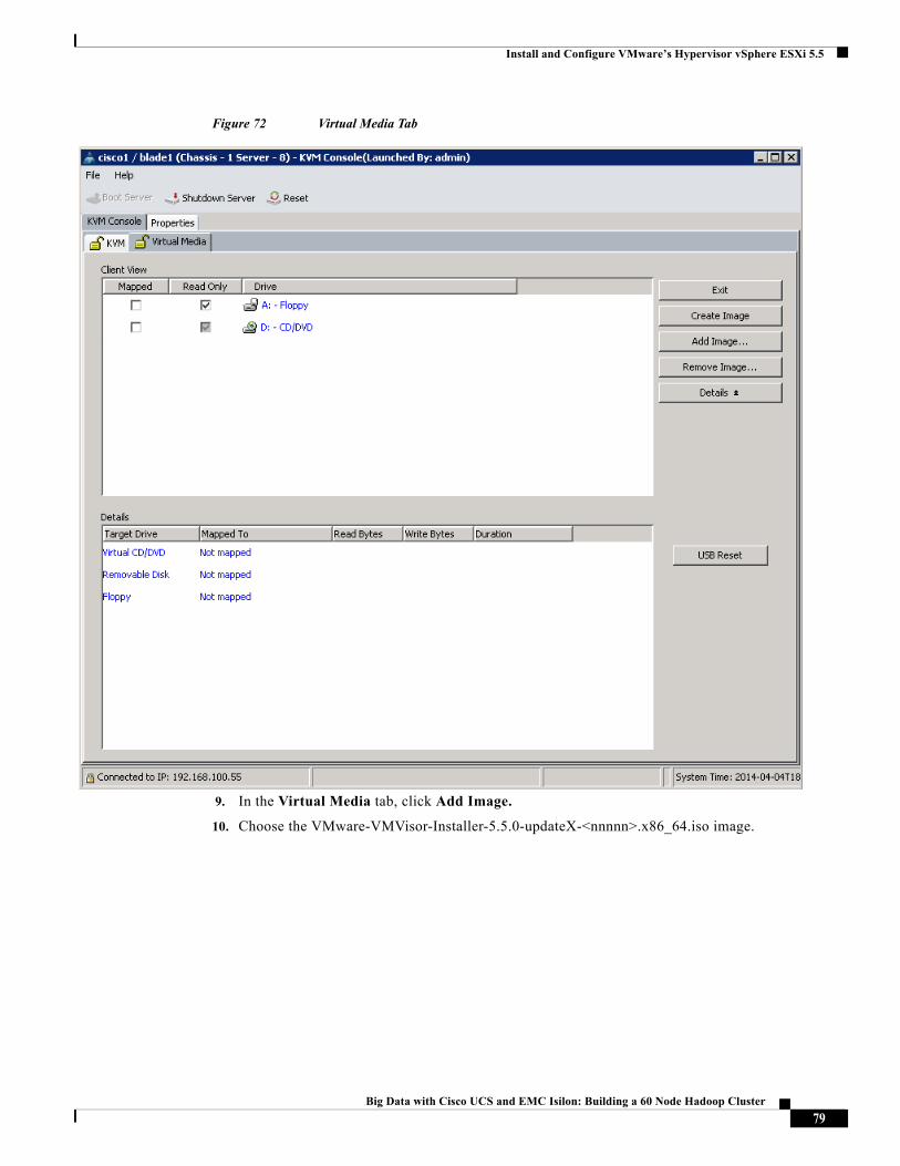
Install and Configure VMware’s Hypervisor vSphere ESXi 5.5
Figure 72 Virtual Media Tab
9. In the Virtual Media tab, click Add Image.
10. Choose the VMware-VMVisor-Installer-5.5.0-updateX-<nnnnn>.x86_64.iso image.
79Big Data with Cisco UCS and EMC Isilon: Building a 60 Node Hadoop Cluster
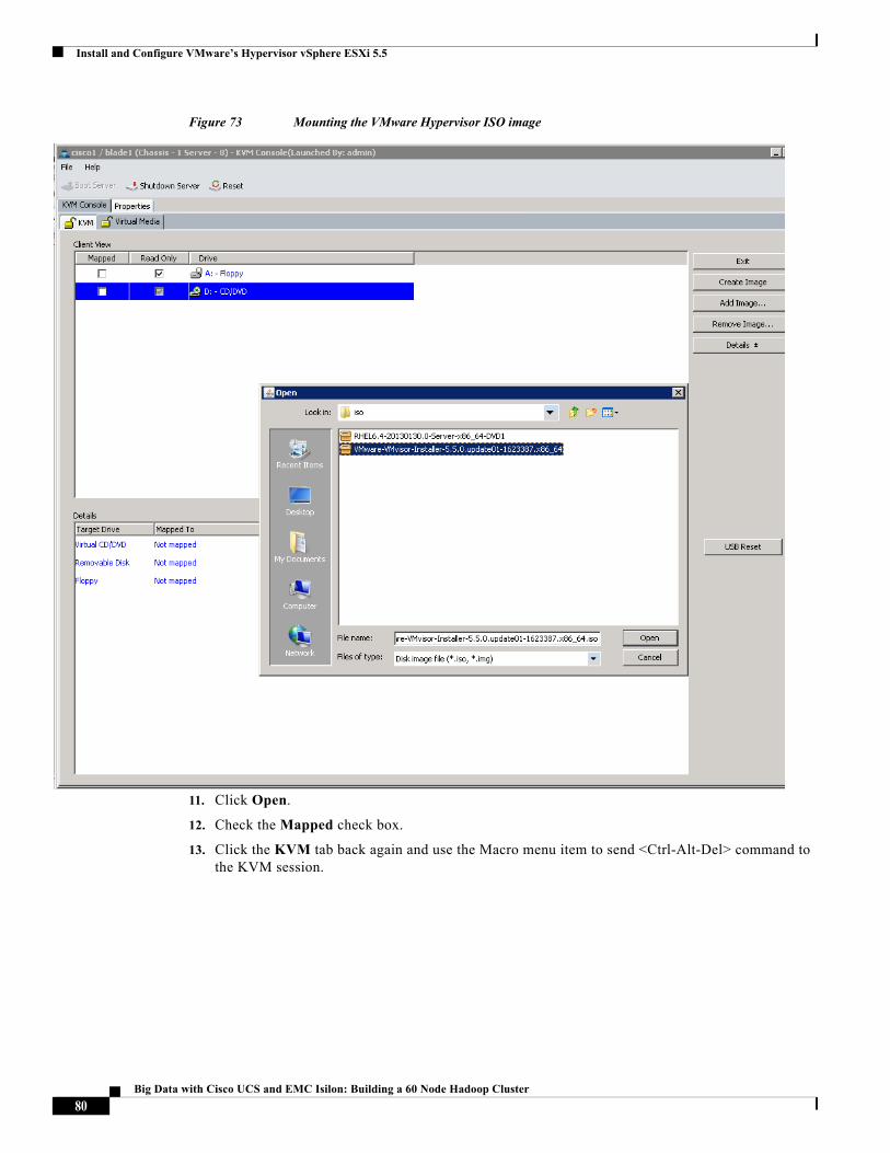
Install and Configure VMware’s Hypervisor vSphere ESXi 5.5
Figure 73 Mounting the VMware Hypervisor ISO image
11. Click Open.
12. Check the Mapped check box.
13. Click the KVM tab back again and use the Macro menu item to send <Ctrl-Alt-Del> command to the KVM session.
80Big Data with Cisco UCS and EMC Isilon: Building a 60 Node Hadoop Cluster
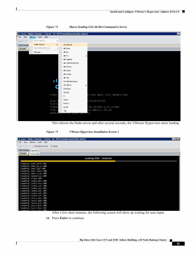
Install and Configure VMware’s Hypervisor vSphere ESXi 5.5
Figure 74 Macro Sending Ctrl-Alt-Del Command to Server
This reboots the blade-server and after several seconds, the VMware Hypervisor starts loading
Figure 75 VMware Hypervisor Installation Screen 1
After a few short minutes, the following screen will show up waiting for user-input.
14. Press Enter to continue.
81Big Data with Cisco UCS and EMC Isilon: Building a 60 Node Hadoop Cluster
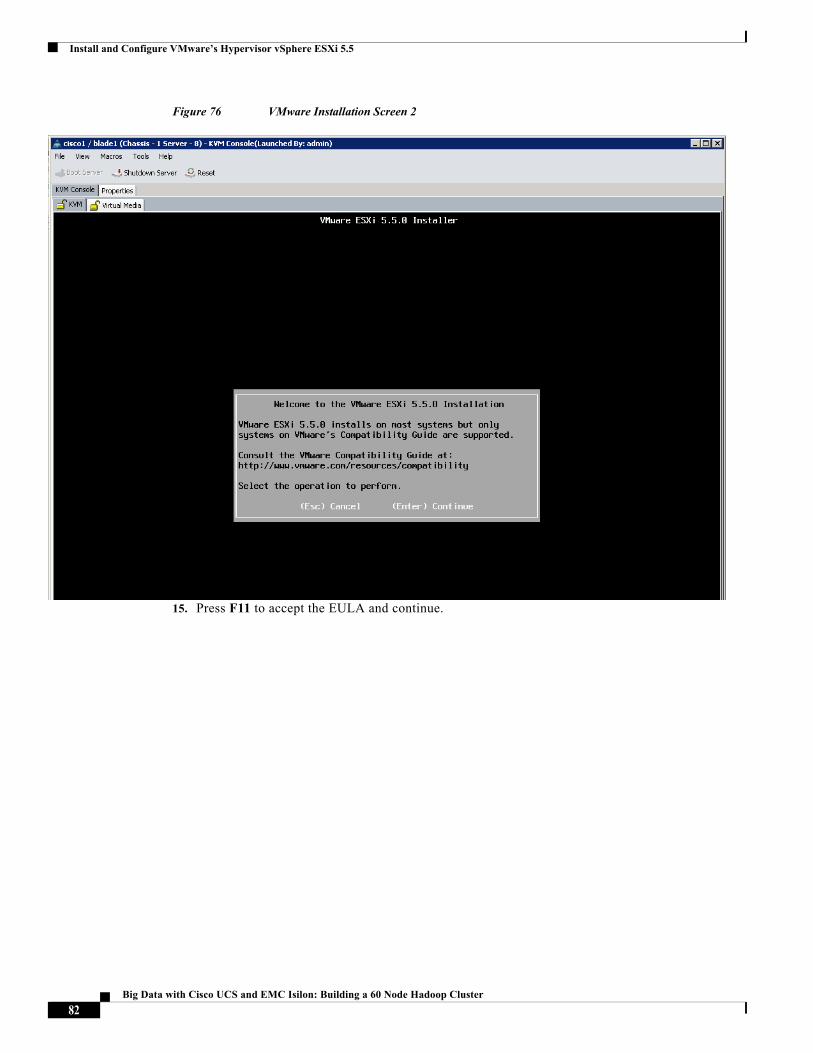
Install and Configure VMware’s Hypervisor vSphere ESXi 5.5
Figure 76 VMware Installation Screen 2
15. Press F11 to accept the EULA and continue.
82Big Data with Cisco UCS and EMC Isilon: Building a 60 Node Hadoop Cluster
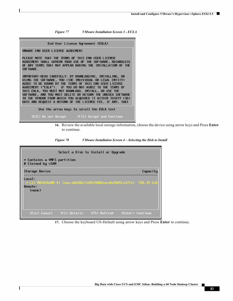
Install and Configure VMware’s Hypervisor vSphere ESXi 5.5
Figure 77 VMware Installation Screen 3 - EULA
16. Review the available local storage information, choose the device using arrow keys and Press Enter to continue.
Figure 78 VMware Installation Screen 4 – Selecting the Disk to Install
17. Choose the keyboard US-Default using arrow keys and Press Enter to continue.
83Big Data with Cisco UCS and EMC Isilon: Building a 60 Node Hadoop Cluster
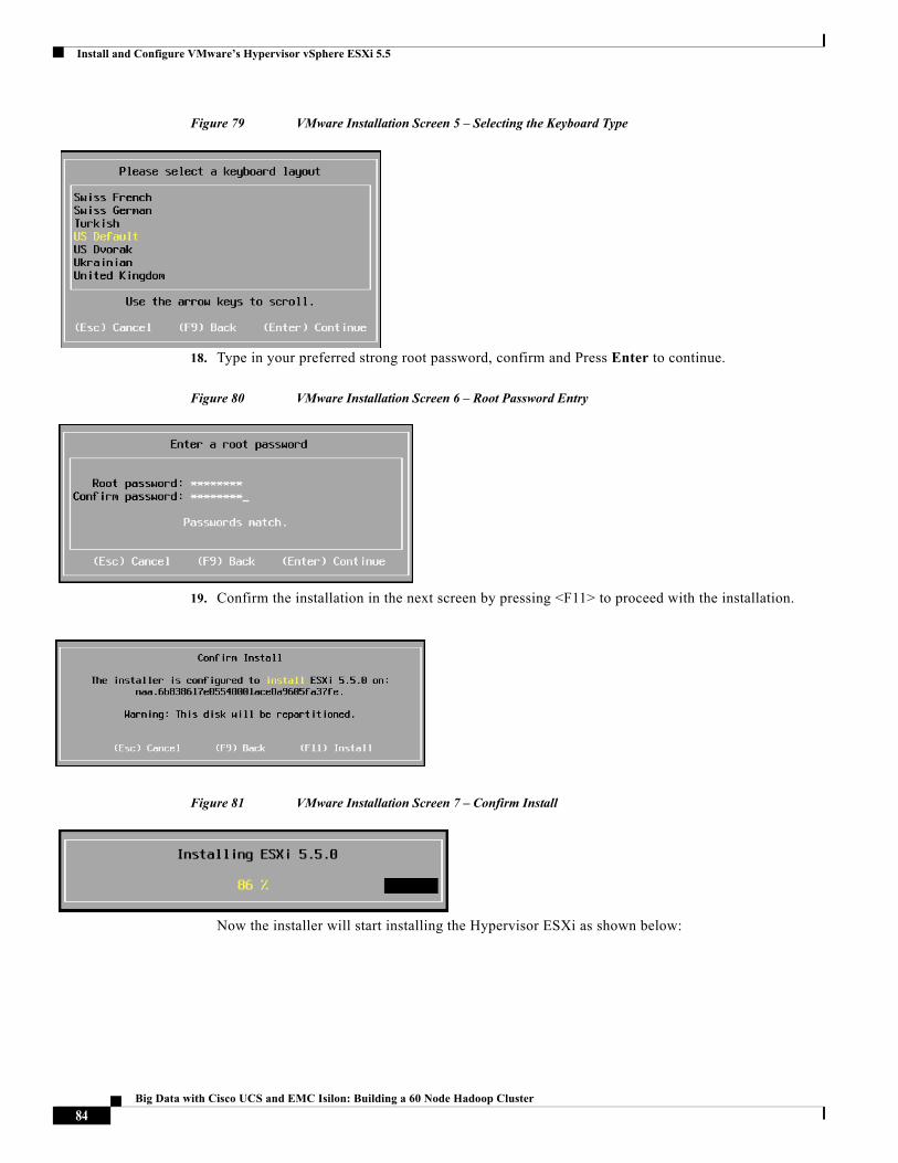
Install and Configure VMware’s Hypervisor vSphere ESXi 5.5
Figure 79 VMware Installation Screen 5 – Selecting the Keyboard Type
18. Type in your preferred strong root password, confirm and Press Enter to continue.
Figure 80 VMware Installation Screen 6 – Root Password Entry
19. Confirm the installation in the next screen by pressing <F11> to proceed with the installation.
Figure 81 VMware Installation Screen 7 – Confirm Install
Now the installer will start installing the Hypervisor ESXi as shown below:
84Big Data with Cisco UCS and EMC Isilon: Building a 60 Node Hadoop Cluster
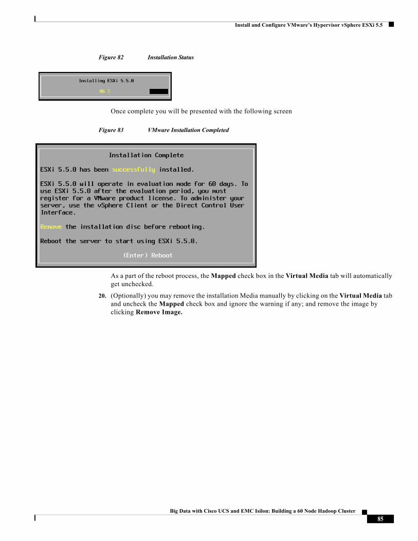
Install and Configure VMware’s Hypervisor vSphere ESXi 5.5
Figure 82 Installation Status
Once complete you will be presented with the following screen
Figure 83 VMware Installation Completed
As a part of the reboot process, the Mapped check box in the Virtual Media tab will automatically get unchecked.
20. (Optionally) you may remove the installation Media manually by clicking on the Virtual Media tab and uncheck the Mapped check box and ignore the warning if any; and remove the image by clicking Remove Image.
85Big Data with Cisco UCS and EMC Isilon: Building a 60 Node Hadoop Cluster
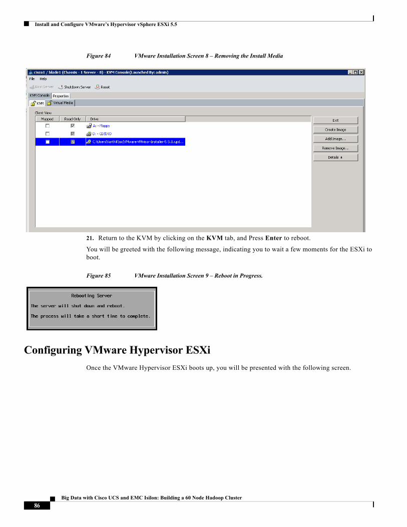
Install and Configure VMware’s Hypervisor vSphere ESXi 5.5
Figure 84 VMware Installation Screen 8 – Removing the Install Media
21. Return to the KVM by clicking on the KVM tab, and Press Enter to reboot.
You will be greeted with the following message, indicating you to wait a few moments for the ESXi to boot.
Figure 85 VMware Installation Screen 9 – Reboot in Progress.
Configuring VMware Hypervisor ESXi
Once the VMware Hypervisor ESXi boots up, you will be presented with the following screen.
86Big Data with Cisco UCS and EMC Isilon: Building a 60 Node Hadoop Cluster
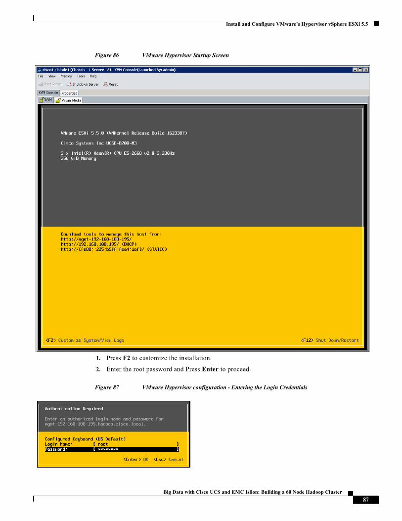
Install and Configure VMware’s Hypervisor vSphere ESXi 5.5
Figure 86 VMware Hypervisor Startup Screen
1. Press F2 to customize the installation.
2. Enter the root password and Press Enter to proceed.
Figure 87 VMware Hypervisor configuration - Entering the Login Credentials
87Big Data with Cisco UCS and EMC Isilon: Building a 60 Node Hadoop Cluster
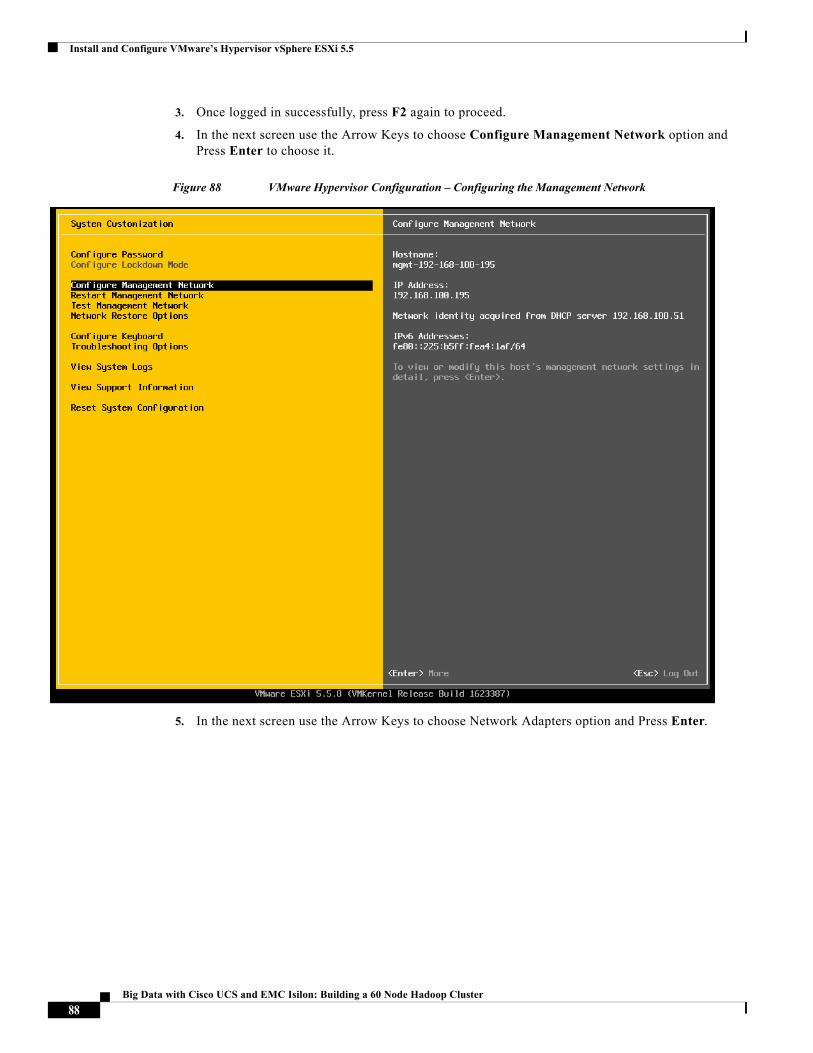
Install and Configure VMware’s Hypervisor vSphere ESXi 5.5
3. Once logged in successfully, press F2 again to proceed.
4. In the next screen use the Arrow Keys to choose Configure Management Network option and Press Enter to choose it.
Figure 88 VMware Hypervisor Configuration – Configuring the Management Network
5. In the next screen use the Arrow Keys to choose Network Adapters option and Press Enter.
88Big Data with Cisco UCS and EMC Isilon: Building a 60 Node Hadoop Cluster
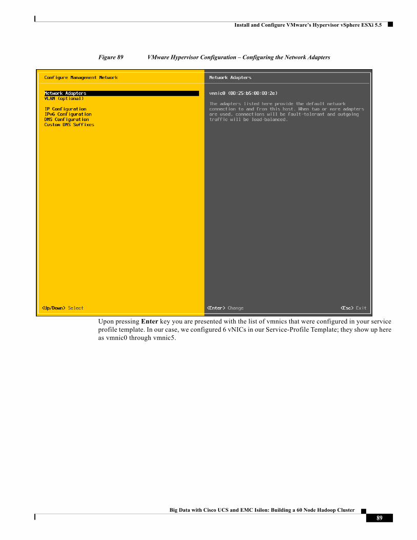
Install and Configure VMware’s Hypervisor vSphere ESXi 5.5
Figure 89 VMware Hypervisor Configuration – Configuring the Network Adapters
Upon pressing Enter key you are presented with the list of vmnics that were configured in your service profile template. In our case, we configured 6 vNICs in our Service-Profile Template; they show up here as vmnic0 through vmnic5.
89Big Data with Cisco UCS and EMC Isilon: Building a 60 Node Hadoop Cluster
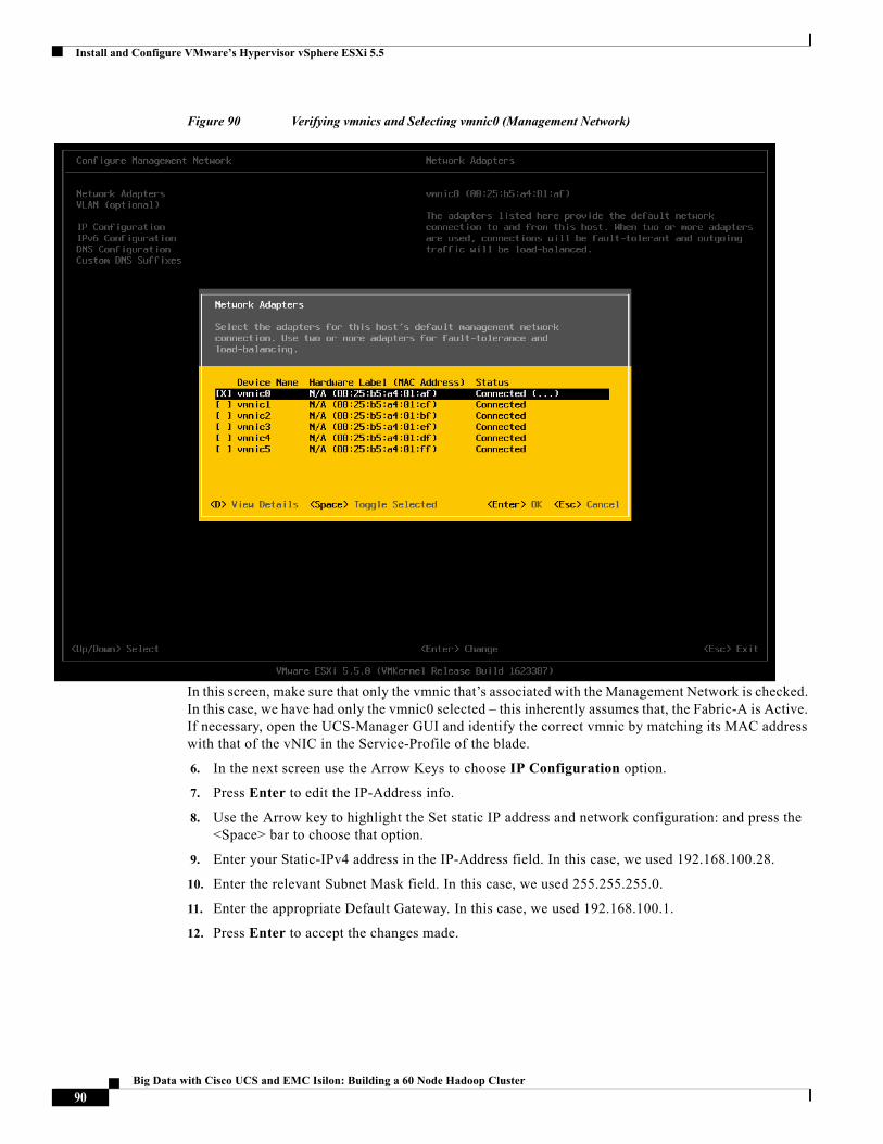
Install and Configure VMware’s Hypervisor vSphere ESXi 5.5
Figure 90 Verifying vmnics and Selecting vmnic0 (Management Network)
In this screen, make sure that only the vmnic that’s associated with the Management Network is checked. In this case, we have had only the vmnic0 selected – this inherently assumes that, the Fabric-A is Active. If necessary, open the UCS-Manager GUI and identify the correct vmnic by matching its MAC address with that of the vNIC in the Service-Profile of the blade.
6. In the next screen use the Arrow Keys to choose IP Configuration option.
7. Press Enter to edit the IP-Address info.
8. Use the Arrow key to highlight the Set static IP address and network configuration: and press the <Space> bar to choose that option.
9. Enter your Static-IPv4 address in the IP-Address field. In this case, we used 192.168.100.28.
10. Enter the relevant Subnet Mask field. In this case, we used 255.255.255.0.
11. Enter the appropriate Default Gateway. In this case, we used 192.168.100.1.
12. Press Enter to accept the changes made.
90Big Data with Cisco UCS and EMC Isilon: Building a 60 Node Hadoop Cluster
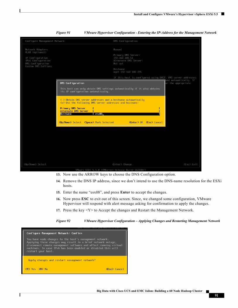
Install and Configure VMware’s Hypervisor vSphere ESXi 5.5
Figure 91 VMware Hypervisor Configuration - Entering the IP-Address for the Management Network
13. Now use the ARROW keys to choose the DNS Configuration option.
14. Remove the DNS IP address, since we don’t intend to use the DNS-name resolution for the ESXi hosts.
15. Enter the name “esx08”, and press Enter to accept the changes.
16. Now press ESC to exit out of this screen. Since, we changed some configuration, VMware Hypervisor will respond with alert message asking for confirmation to apply the changes.
17. Press the key <Y> to Accept the changes and Restart the Management Network.
Figure 92 VMware Hypervisor Configuration – Applying Changes and Restarting Management Network
91Big Data with Cisco UCS and EMC Isilon: Building a 60 Node Hadoop Cluster
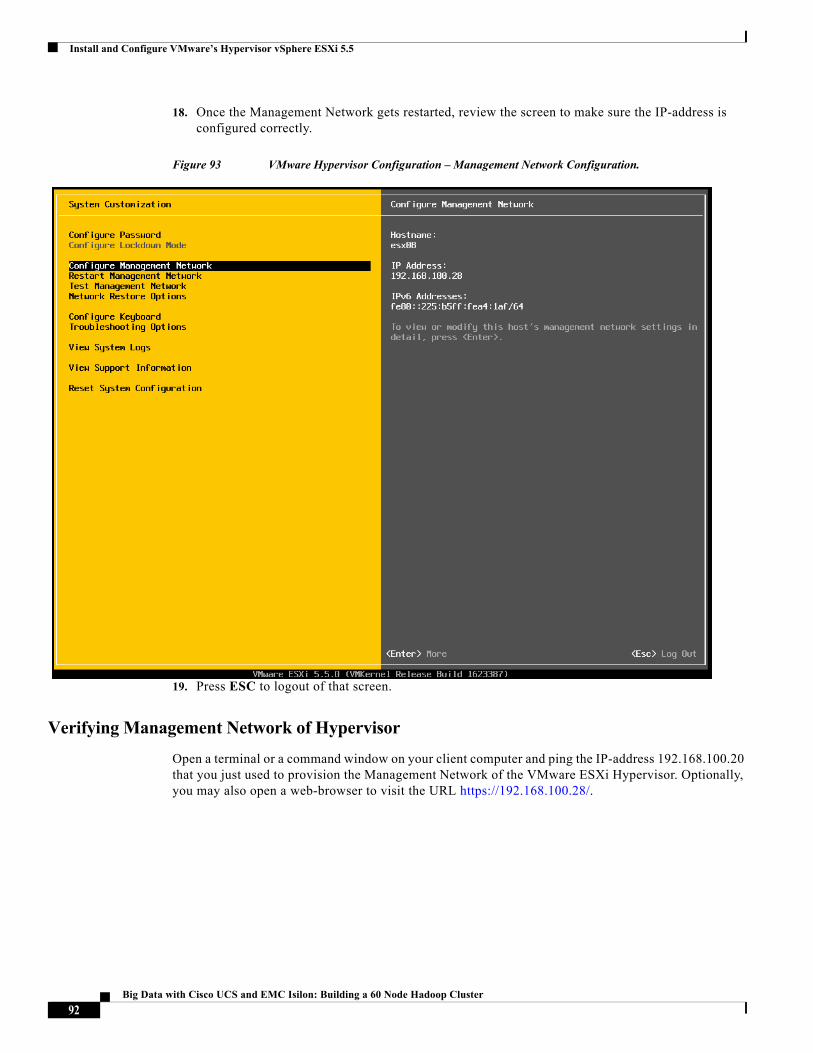
Install and Configure VMware’s Hypervisor vSphere ESXi 5.5
18. Once the Management Network gets restarted, review the screen to make sure the IP-address is configured correctly.
Figure 93 VMware Hypervisor Configuration – Management Network Configuration.
19. Press ESC to logout of that screen.
Verifying Management Network of Hypervisor
Open a terminal or a command window on your client computer and ping the IP-address 192.168.100.20 that you just used to provision the Management Network of the VMware ESXi Hypervisor. Optionally, you may also open a web-browser to visit the URL https://192.168.100.28/.
92Big Data with Cisco UCS and EMC Isilon: Building a 60 Node Hadoop Cluster
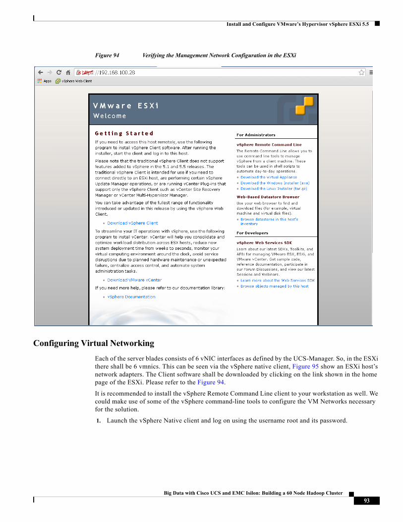
Install and Configure VMware’s Hypervisor vSphere ESXi 5.5
Figure 94 Verifying the Management Network Configuration in the ESXi
Configuring Virtual Networking
Each of the server blades consists of 6 vNIC interfaces as defined by the UCS-Manager. So, in the ESXi there shall be 6 vmnics. This can be seen via the vSphere native client, Figure 95 show an ESXi host’s network adapters. The Client software shall be downloaded by clicking on the link shown in the home page of the ESXi. Please refer to the Figure 94.
It is recommended to install the vSphere Remote Command Line client to your workstation as well. We could make use of some of the vSphere command-line tools to configure the VM Networks necessary for the solution.
1. Launch the vSphere Native client and log on using the username root and its password.
93Big Data with Cisco UCS and EMC Isilon: Building a 60 Node Hadoop Cluster
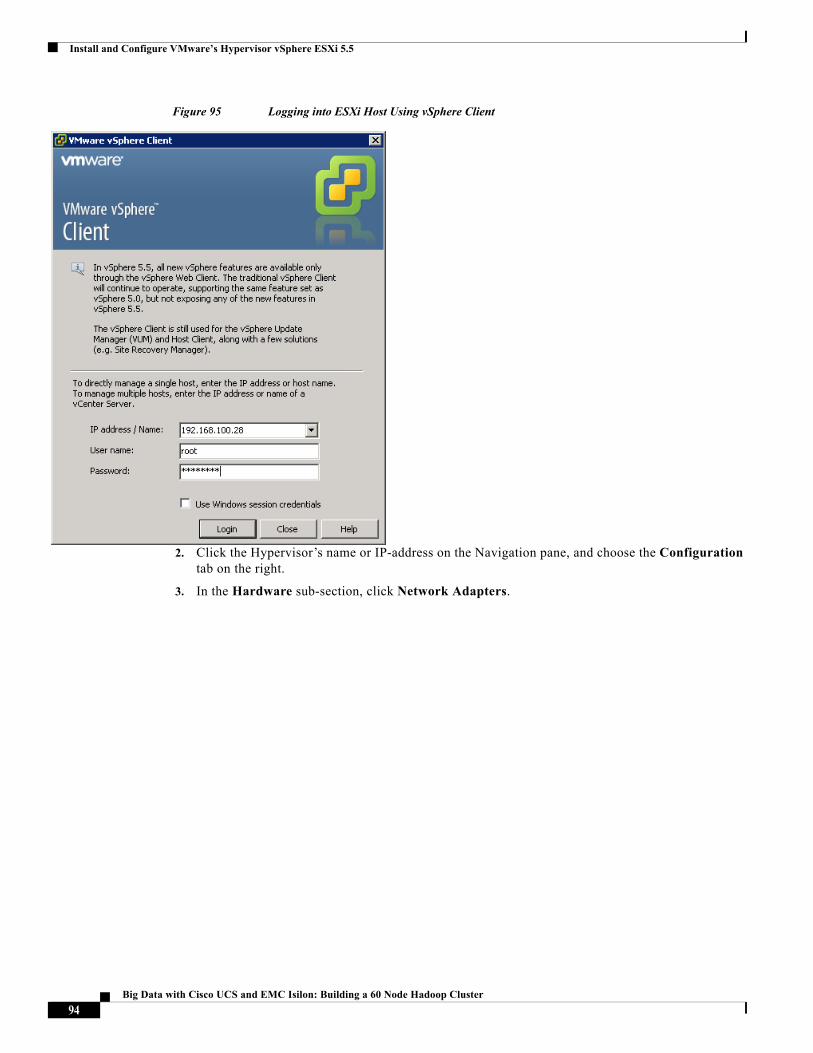
Install and Configure VMware’s Hypervisor vSphere ESXi 5.5
Figure 95 Logging into ESXi Host Using vSphere Client
2. Click the Hypervisor’s name or IP-address on the Navigation pane, and choose the Configuration tab on the right.
3. In the Hardware sub-section, click Network Adapters.
94Big Data with Cisco UCS and EMC Isilon: Building a 60 Node Hadoop Cluster
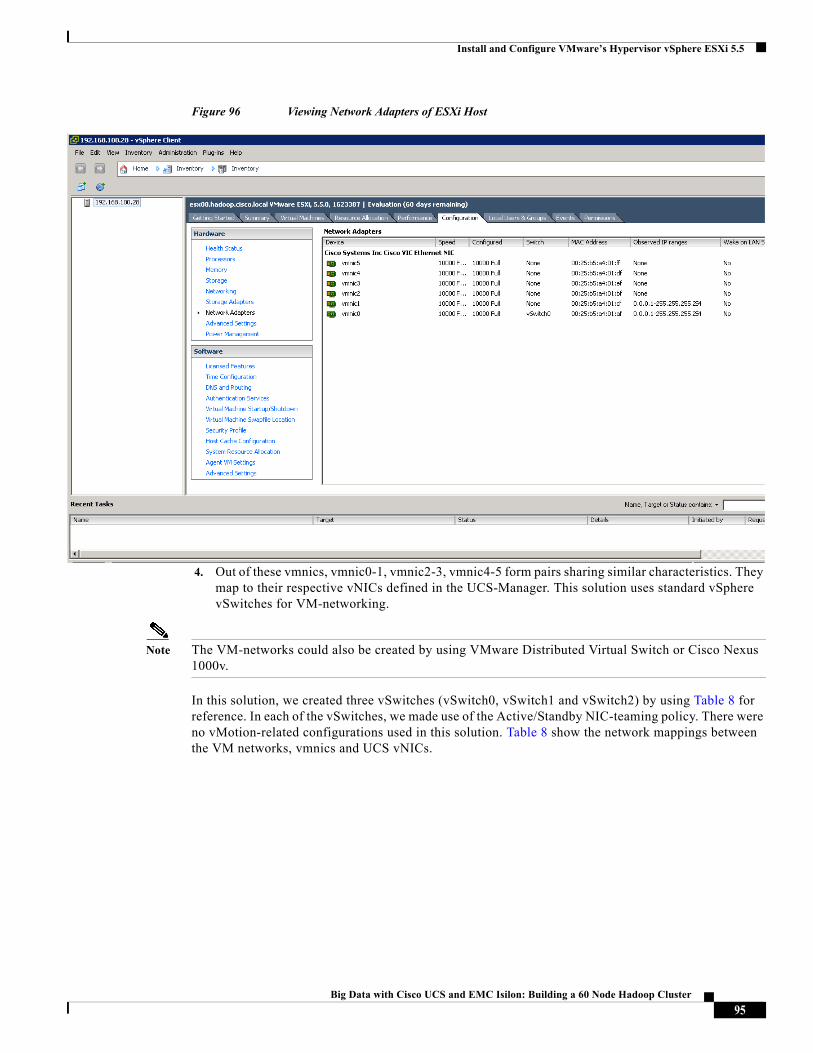
Install and Configure VMware’s Hypervisor vSphere ESXi 5.5
Figure 96 Viewing Network Adapters of ESXi Host
4. Out of these vmnics, vmnic0-1, vmnic2-3, vmnic4-5 form pairs sharing similar characteristics. They map to their respective vNICs defined in the UCS-Manager. This solution uses standard vSphere vSwitches for VM-networking.
Note The VM-networks could also be created by using VMware Distributed Virtual Switch or Cisco Nexus 1000v.
In this solution, we created three vSwitches (vSwitch0, vSwitch1 and vSwitch2) by using Table 8 for reference. In each of the vSwitches, we made use of the Active/Standby NIC-teaming policy. There were no vMotion-related configurations used in this solution. Table 8 show the network mappings between the VM networks, vmnics and UCS vNICs.
95Big Data with Cisco UCS and EMC Isilon: Building a 60 Node Hadoop Cluster
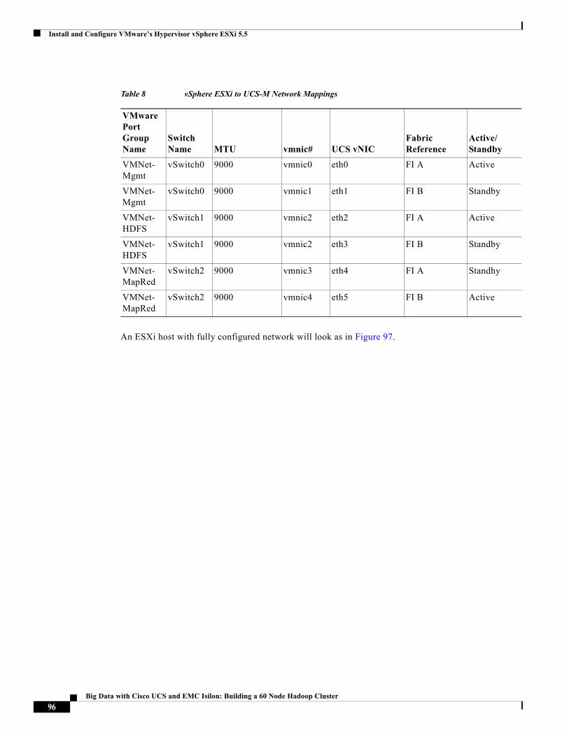
Install and Configure VMware’s Hypervisor vSphere ESXi 5.5
An ESXi host with fully configured network will look as in Figure 97.
Table 8 vSphere ESXi to UCS-M Network Mappings
VMware Port Group Name
Switch Name MTU vmnic# UCS vNIC
Fabric Reference
Active/Standby
VMNet-Mgmt
vSwitch0 9000 vmnic0 eth0 FI A Active
VMNet-Mgmt
vSwitch0 9000 vmnic1 eth1 FI B Standby
VMNet-HDFS
vSwitch1 9000 vmnic2 eth2 FI A Active
VMNet-HDFS
vSwitch1 9000 vmnic2 eth3 FI B Standby
VMNet-MapRed
vSwitch2 9000 vmnic3 eth4 FI A Standhy
VMNet-MapRed
vSwitch2 9000 vmnic4 eth5 FI B Active
96Big Data with Cisco UCS and EMC Isilon: Building a 60 Node Hadoop Cluster
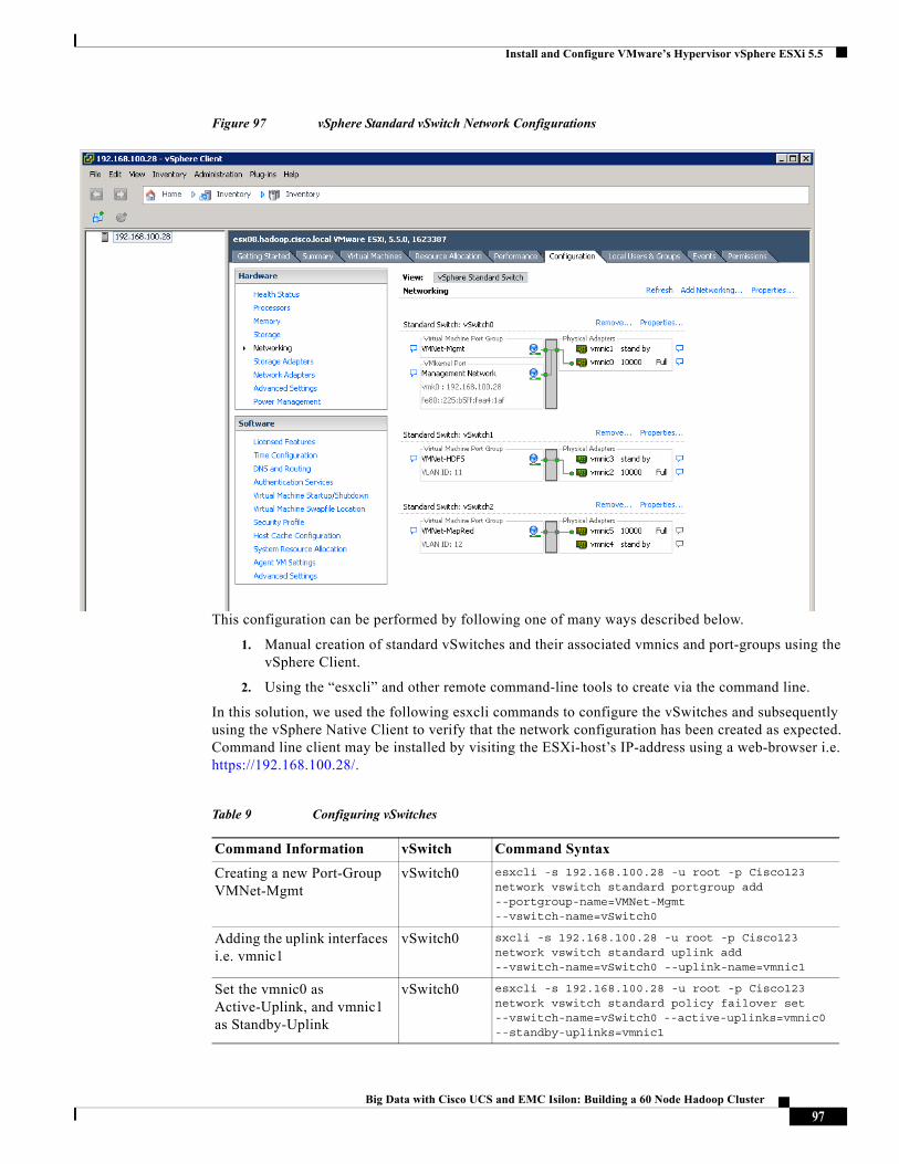
Install and Configure VMware’s Hypervisor vSphere ESXi 5.5
Figure 97 vSphere Standard vSwitch Network Configurations
This configuration can be performed by following one of many ways described below.
1. Manual creation of standard vSwitches and their associated vmnics and port-groups using the vSphere Client.
2. Using the “esxcli” and other remote command-line tools to create via the command line.
In this solution, we used the following esxcli commands to configure the vSwitches and subsequently using the vSphere Native Client to verify that the network configuration has been created as expected. Command line client may be installed by visiting the ESXi-host’s IP-address using a web-browser i.e. https://192.168.100.28/.
Table 9 Configuring vSwitches
Command Information vSwitch Command Syntax
Creating a new Port-Group VMNet-Mgmt
vSwitch0 esxcli -s 192.168.100.28 -u root -p Cisco123 network vswitch standard portgroup add --portgroup-name=VMNet-Mgmt --vswitch-name=vSwitch0
Adding the uplink interfaces i.e. vmnic1
vSwitch0 sxcli -s 192.168.100.28 -u root -p Cisco123 network vswitch standard uplink add --vswitch-name=vSwitch0 --uplink-name=vmnic1
Set the vmnic0 as Active-Uplink, and vmnic1 as Standby-Uplink
vSwitch0 esxcli -s 192.168.100.28 -u root -p Cisco123 network vswitch standard policy failover set --vswitch-name=vSwitch0 --active-uplinks=vmnic0 --standby-uplinks=vmnic1
97Big Data with Cisco UCS and EMC Isilon: Building a 60 Node Hadoop Cluster
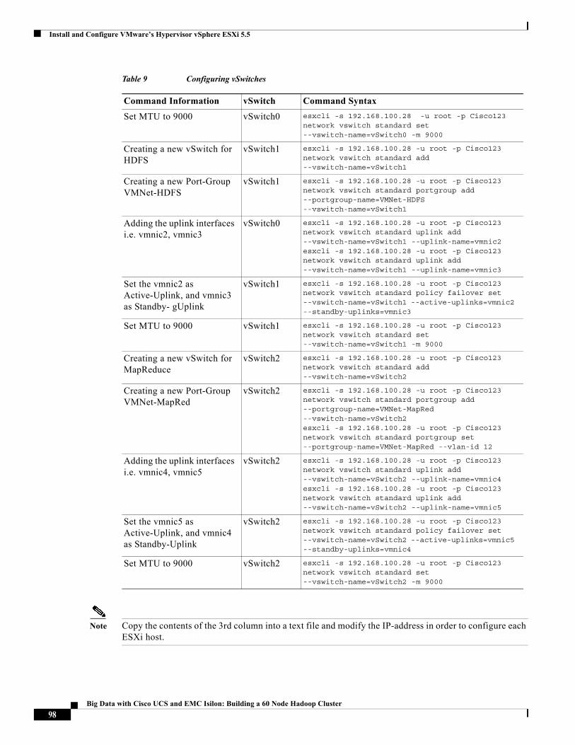
Install and Configure VMware’s Hypervisor vSphere ESXi 5.5
Note Copy the contents of the 3rd column into a text file and modify the IP-address in order to configure each ESXi host.
Set MTU to 9000 vSwitch0 esxcli -s 192.168.100.28 -u root -p Cisco123 network vswitch standard set --vswitch-name=vSwitch0 -m 9000
Creating a new vSwitch for HDFS
vSwitch1 esxcli -s 192.168.100.28 -u root -p Cisco123 network vswitch standard add --vswitch-name=vSwitch1
Creating a new Port-Group VMNet-HDFS
vSwitch1 esxcli -s 192.168.100.28 -u root -p Cisco123 network vswitch standard portgroup add --portgroup-name=VMNet-HDFS --vswitch-name=vSwitch1
Adding the uplink interfaces i.e. vmnic2, vmnic3
vSwitch0 esxcli -s 192.168.100.28 -u root -p Cisco123 network vswitch standard uplink add --vswitch-name=vSwitch1 --uplink-name=vmnic2esxcli -s 192.168.100.28 -u root -p Cisco123 network vswitch standard uplink add --vswitch-name=vSwitch1 --uplink-name=vmnic3
Set the vmnic2 as Active-Uplink, and vmnic3 as Standby- gUplink
vSwitch1 esxcli -s 192.168.100.28 -u root -p Cisco123 network vswitch standard policy failover set --vswitch-name=vSwitch1 --active-uplinks=vmnic2 --standby-uplinks=vmnic3
Set MTU to 9000 vSwitch1 esxcli -s 192.168.100.28 -u root -p Cisco123 network vswitch standard set --vswitch-name=vSwitch1 -m 9000
Creating a new vSwitch for MapReduce
vSwitch2 esxcli -s 192.168.100.28 -u root -p Cisco123 network vswitch standard add --vswitch-name=vSwitch2
Creating a new Port-Group VMNet-MapRed
vSwitch2 esxcli -s 192.168.100.28 -u root -p Cisco123 network vswitch standard portgroup add --portgroup-name=VMNet-MapRed --vswitch-name=vSwitch2esxcli -s 192.168.100.28 -u root -p Cisco123 network vswitch standard portgroup set --portgroup-name=VMNet-MapRed --vlan-id 12
Adding the uplink interfaces i.e. vmnic4, vmnic5
vSwitch2 esxcli -s 192.168.100.28 -u root -p Cisco123 network vswitch standard uplink add --vswitch-name=vSwitch2 --uplink-name=vmnic4esxcli -s 192.168.100.28 -u root -p Cisco123 network vswitch standard uplink add --vswitch-name=vSwitch2 --uplink-name=vmnic5
Set the vmnic5 as Active-Uplink, and vmnic4 as Standby-Uplink
vSwitch2 esxcli -s 192.168.100.28 -u root -p Cisco123 network vswitch standard policy failover set --vswitch-name=vSwitch2 --active-uplinks=vmnic5 --standby-uplinks=vmnic4
Set MTU to 9000 vSwitch2 esxcli -s 192.168.100.28 -u root -p Cisco123 network vswitch standard set --vswitch-name=vSwitch2 -m 9000
Table 9 Configuring vSwitches
Command Information vSwitch Command Syntax
98Big Data with Cisco UCS and EMC Isilon: Building a 60 Node Hadoop Cluster
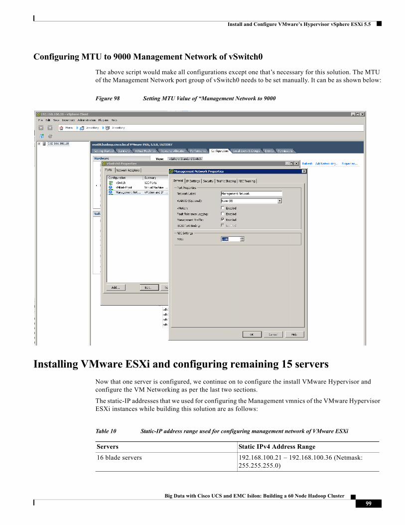
Install and Configure VMware’s Hypervisor vSphere ESXi 5.5
Configuring MTU to 9000 Management Network of vSwitch0
The above script would make all configurations except one that’s necessary for this solution. The MTU of the Management Network port group of vSwitch0 needs to be set manually. It can be as shown below:
Figure 98 Setting MTU Value of “Management Network to 9000
Installing VMware ESXi and configuring remaining 15 servers
Now that one server is configured, we continue on to configure the install VMware Hypervisor and configure the VM Networking as per the last two sections.
The static-IP addresses that we used for configuring the Management vmnics of the VMware Hypervisor ESXi instances while building this solution are as follows:
Table 10 Static-IP address range used for configuring management network of VMware ESXi
Servers Static IPv4 Address Range
16 blade servers 192.168.100.21 – 192.168.100.36 (Netmask: 255.255.255.0)
99Big Data with Cisco UCS and EMC Isilon: Building a 60 Node Hadoop Cluster
VMware vCenter Server
VMware vCenter ServerThis section provides information on installing the VMware vCenter Server and the vSphere client software packages. There are two ways to install the vCenter Server.
1. Install vCenter Server on a Windows Server i.e. server with Windows Server 2008R2.
2. Install vCenter Server as an appliance.
While building out this solution, we went with Option 2—installed the vCenter Virtual-Appliance 5.5 on a server in the Admin DRS-cluster.
In this solution we used both the Native vSphere-Client and vSphere Web-Client. Please note that, as mentioned in the pre-requisites in 14.1, vSphere Web-Client is a requirement for installing Big-Data-Extensions. The vCenter Server Appliance comes pre-packaged with vSphere Web-Client, so no other installation is required.
Installing the vCenter Server Virtual Appliance
1. Download vCenter Server Virtual Appliance ISO file from the vmware website http://www.vmware.com/downloads.
2. Using the vSphere Native client, log into ESXi host 192.168.100.21.
3. From the File menu choose Deploy OVF Template option.
4. Choose the VMware-vCenter-Server-Appliance OVF file by using the <Browse> button. Click Next.
100Big Data with Cisco UCS and EMC Isilon: Building a 60 Node Hadoop Cluster
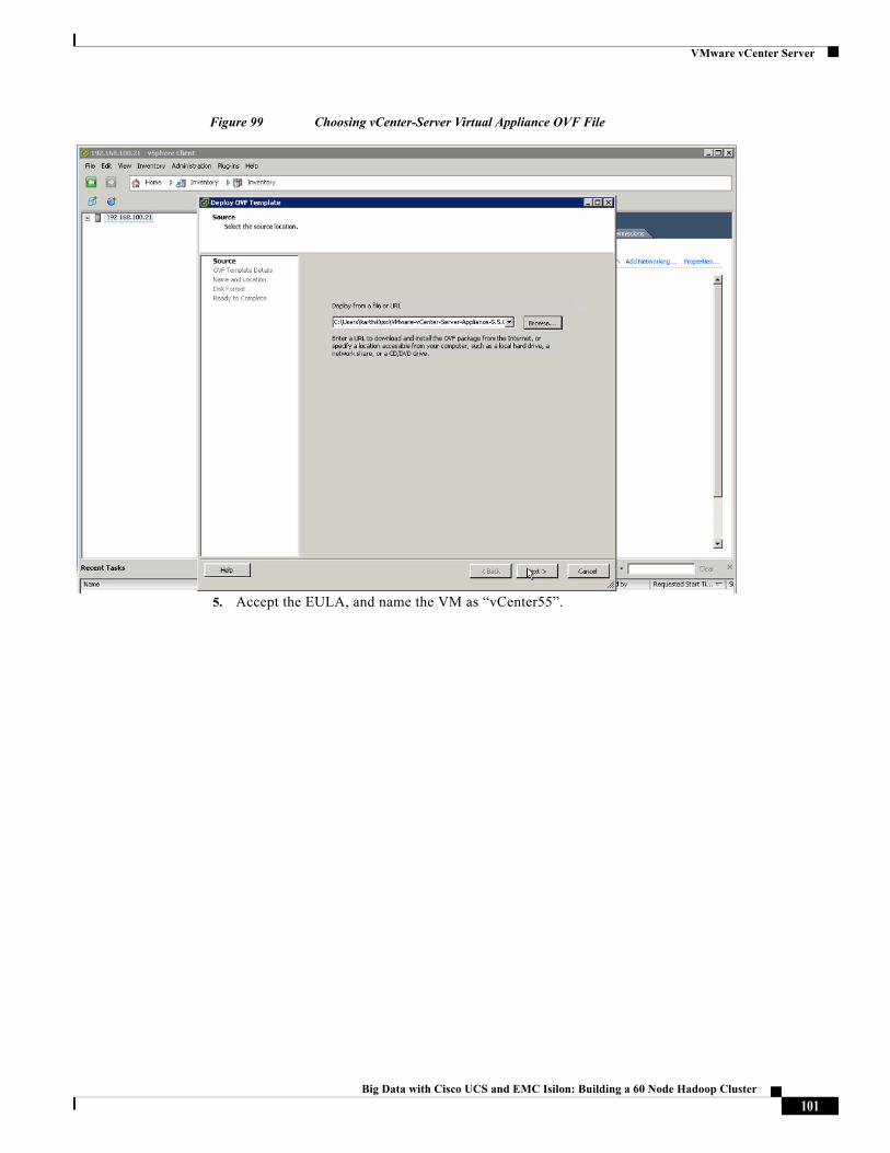
VMware vCenter Server
Figure 99 Choosing vCenter-Server Virtual Appliance OVF File
5. Accept the EULA, and name the VM as “vCenter55”.
101Big Data with Cisco UCS and EMC Isilon: Building a 60 Node Hadoop Cluster
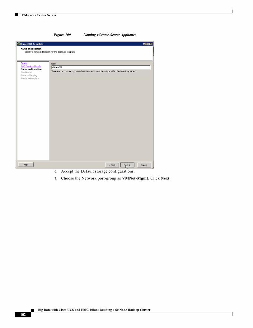
VMware vCenter Server
Figure 100 Naming vCenter-Server Appliance
6. Accept the Default storage configurations.
7. Choose the Network port-group as VMNet-Mgmt. Click Next.
102Big Data with Cisco UCS and EMC Isilon: Building a 60 Node Hadoop Cluster
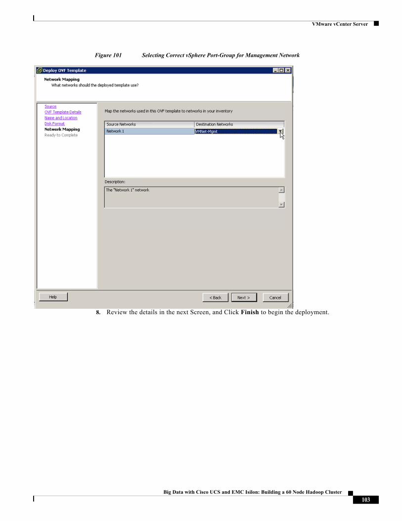
VMware vCenter Server
Figure 101 Selecting Correct vSphere Port-Group for Management Network
8. Review the details in the next Screen, and Click Finish to begin the deployment.
103Big Data with Cisco UCS and EMC Isilon: Building a 60 Node Hadoop Cluster
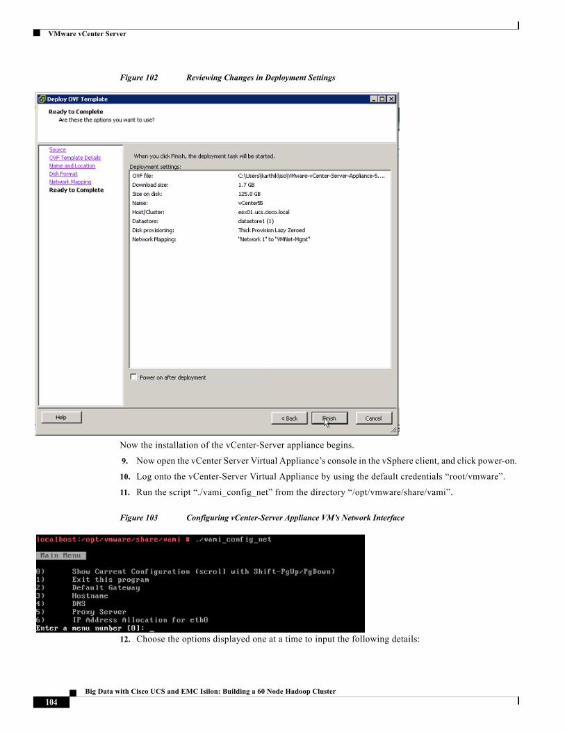
VMware vCenter Server
Figure 102 Reviewing Changes in Deployment Settings
Now the installation of the vCenter-Server appliance begins.
9. Now open the vCenter Server Virtual Appliance’s console in the vSphere client, and click power-on.
10. Log onto the vCenter-Server Virtual Appliance by using the default credentials “root/vmware”.
11. Run the script “./vami_config_net” from the directory “/opt/vmware/share/vami”.
Figure 103 Configuring vCenter-Server Appliance VM’s Network Interface
12. Choose the options displayed one at a time to input the following details:
104Big Data with Cisco UCS and EMC Isilon: Building a 60 Node Hadoop Cluster
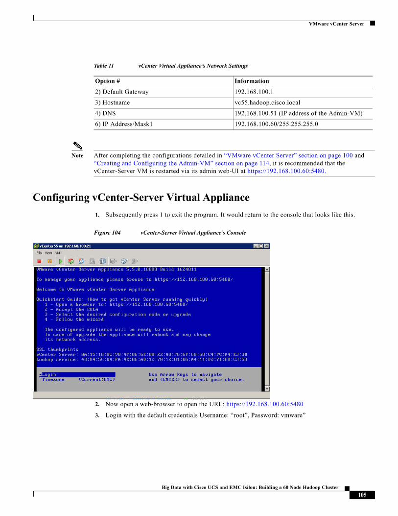
VMware vCenter Server
Note After completing the configurations detailed in “VMware vCenter Server” section on page 100 and “Creating and Configuring the Admin-VM” section on page 114, it is recommended that the vCenter-Server VM is restarted via its admin web-UI at https://192.168.100.60:5480.
Configuring vCenter-Server Virtual Appliance
1. Subsequently press 1 to exit the program. It would return to the console that looks like this.
Figure 104 vCenter-Server Virtual Appliance’s Console
2. Now open a web-browser to open the URL: https://192.168.100.60:5480
3. Login with the default credentials Username: “root”, Password: vmware”
Table 11 vCenter Virtual Appliance’s Network Settings
Option # Information
2) Default Gateway 192.168.100.1
3) Hostname vc55.hadoop.cisco.local
4) DNS 192.168.100.51 (IP address of the Admin-VM)
6) IP Address/Mask1 192.168.100.60/255.255.255.0
105Big Data with Cisco UCS and EMC Isilon: Building a 60 Node Hadoop Cluster
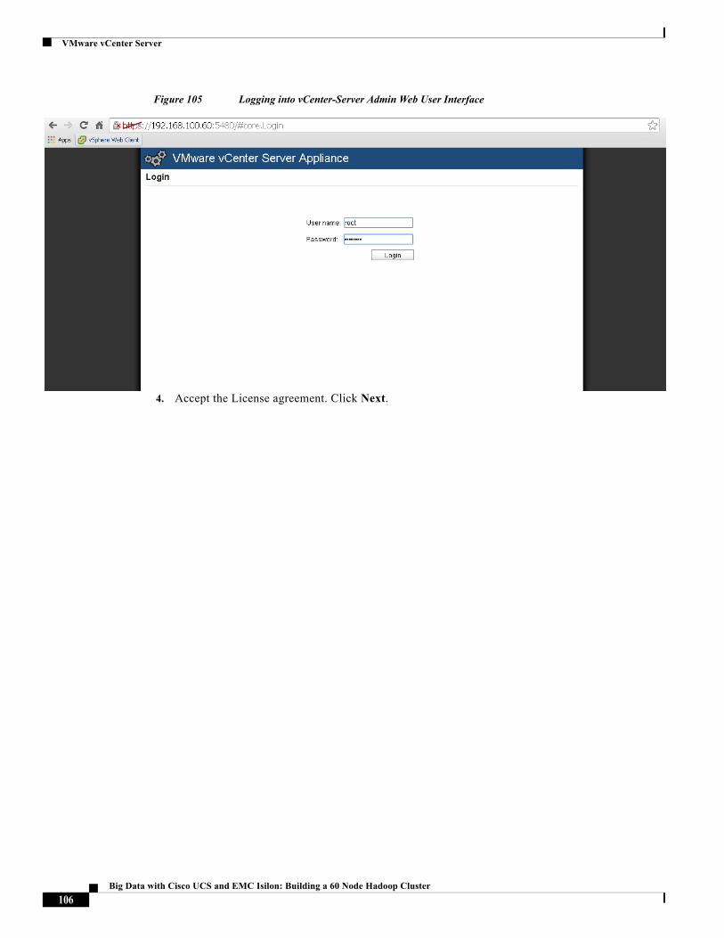
VMware vCenter Server
Figure 105 Logging into vCenter-Server Admin Web User Interface
4. Accept the License agreement. Click Next.
106Big Data with Cisco UCS and EMC Isilon: Building a 60 Node Hadoop Cluster
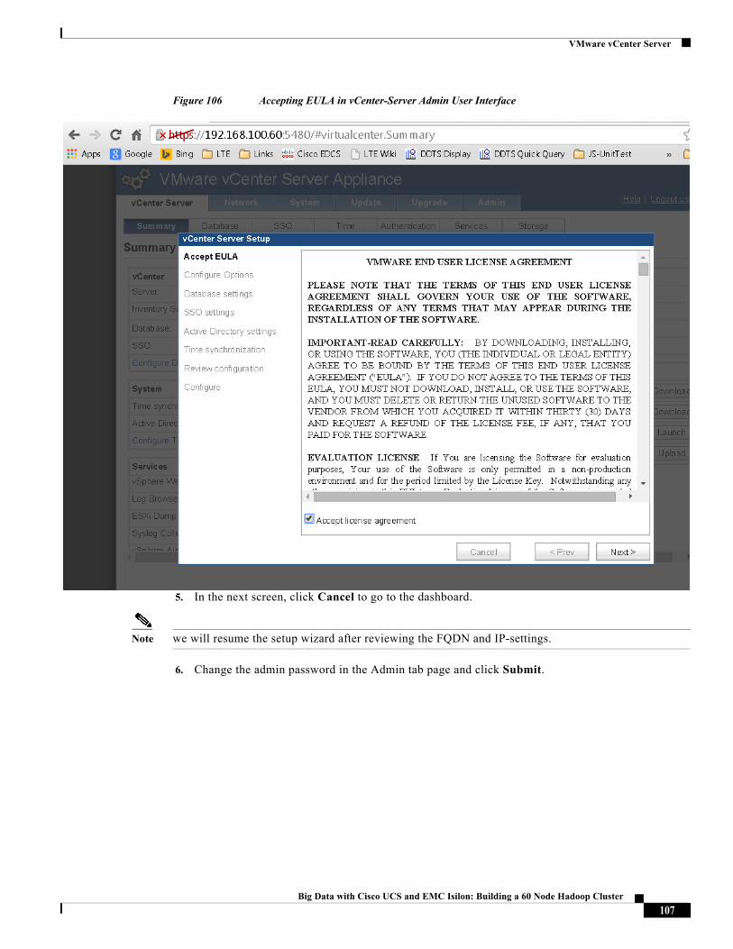
VMware vCenter Server
Figure 106 Accepting EULA in vCenter-Server Admin User Interface
5. In the next screen, click Cancel to go to the dashboard.
Note we will resume the setup wizard after reviewing the FQDN and IP-settings.
6. Change the admin password in the Admin tab page and click Submit.
107Big Data with Cisco UCS and EMC Isilon: Building a 60 Node Hadoop Cluster
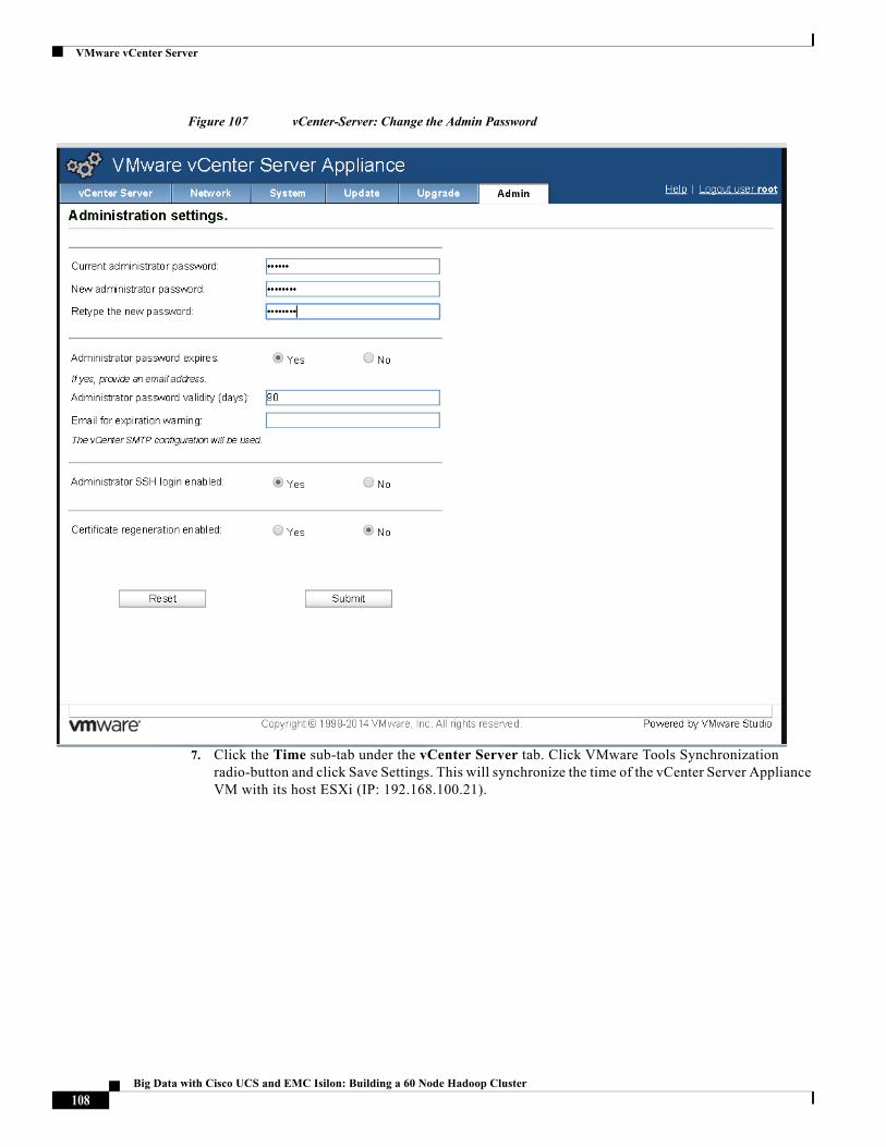
VMware vCenter Server
Figure 107 vCenter-Server: Change the Admin Password
7. Click the Time sub-tab under the vCenter Server tab. Click VMware Tools Synchronization radio-button and click Save Settings. This will synchronize the time of the vCenter Server Appliance VM with its host ESXi (IP: 192.168.100.21).
108Big Data with Cisco UCS and EMC Isilon: Building a 60 Node Hadoop Cluster
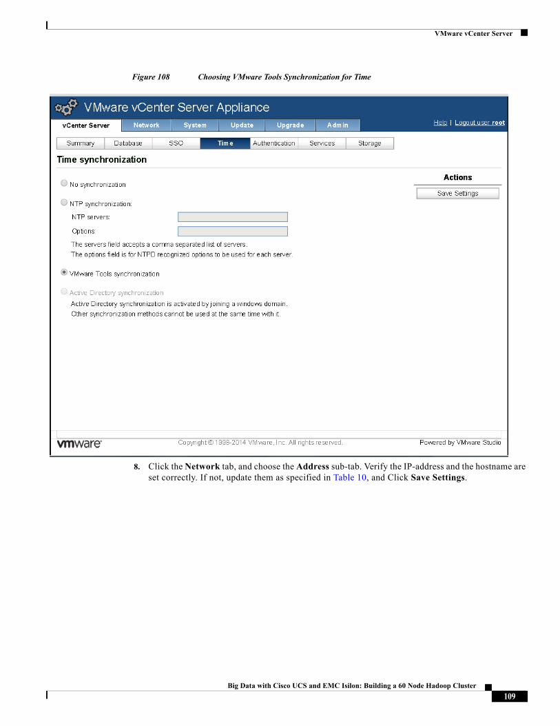
VMware vCenter Server
Figure 108 Choosing VMware Tools Synchronization for Time
8. Click the Network tab, and choose the Address sub-tab. Verify the IP-address and the hostname are set correctly. If not, update them as specified in Table 10, and Click Save Settings.
109Big Data with Cisco UCS and EMC Isilon: Building a 60 Node Hadoop Cluster
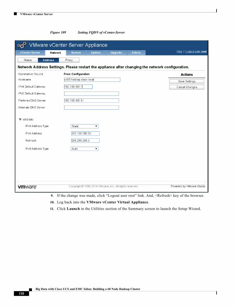
VMware vCenter Server
Figure 109 Setting FQDN of vCenter-Server
9. If the change was made, click “Logout user root” link. And, <Refresh> key of the browser.
10. Log back into the VMware vCenter Virtual Appliance.
11. Click Launch in the Utilities section of the Summary screen to launch the Setup Wizard.
110Big Data with Cisco UCS and EMC Isilon: Building a 60 Node Hadoop Cluster
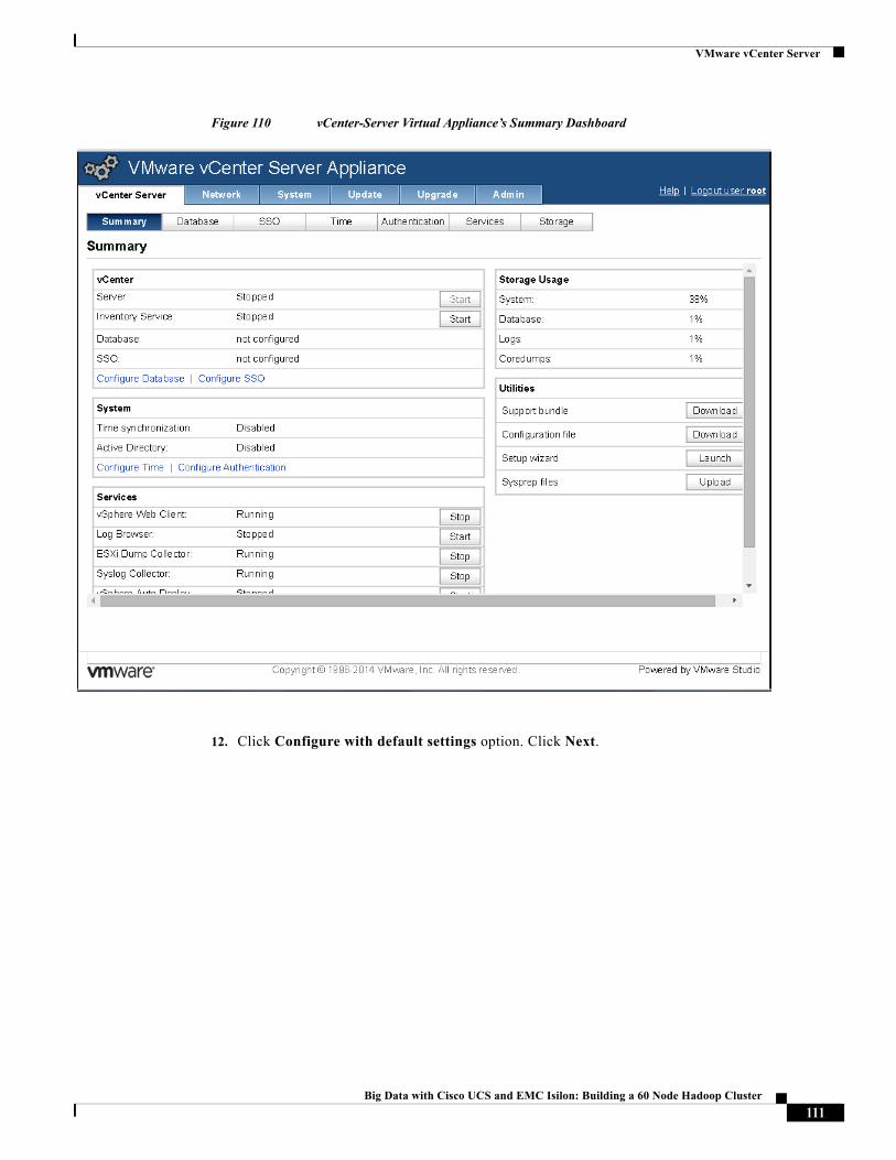
VMware vCenter Server
Figure 110 vCenter-Server Virtual Appliance’s Summary Dashboard
12. Click Configure with default settings option. Click Next.
111Big Data with Cisco UCS and EMC Isilon: Building a 60 Node Hadoop Cluster

VMware vCenter Server
Figure 111 vCenter-Server: Choose Default settings
13. Click Start to start the vCenter services.
112Big Data with Cisco UCS and EMC Isilon: Building a 60 Node Hadoop Cluster
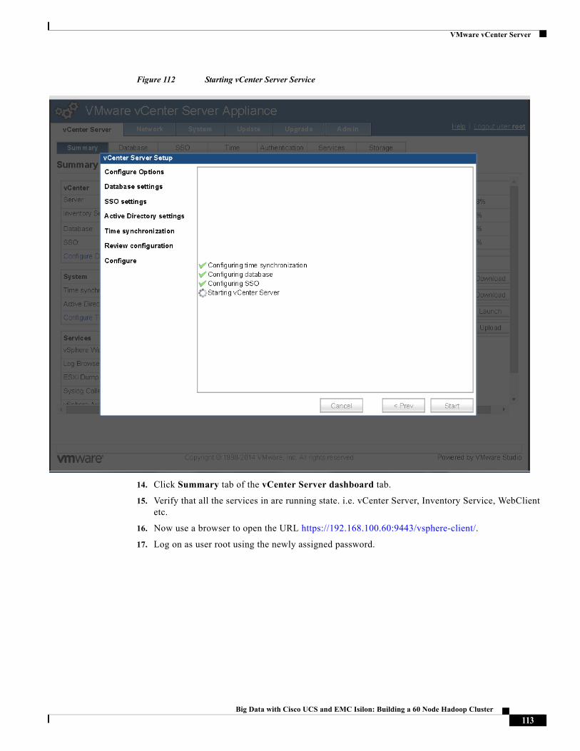
VMware vCenter Server
Figure 112 Starting vCenter Server Service
14. Click Summary tab of the vCenter Server dashboard tab.
15. Verify that all the services in are running state. i.e. vCenter Server, Inventory Service, WebClient etc.
16. Now use a browser to open the URL https://192.168.100.60:9443/vsphere-client/.
17. Log on as user root using the newly assigned password.
113Big Data with Cisco UCS and EMC Isilon: Building a 60 Node Hadoop Cluster
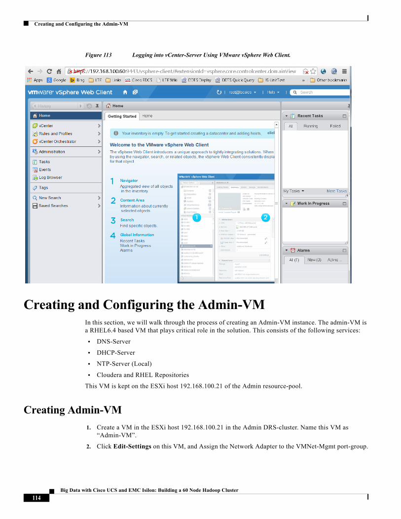
Creating and Configuring the Admin-VM
Figure 113 Logging into vCenter-Server Using VMware vSphere Web Client.
Creating and Configuring the Admin-VMIn this section, we will walk through the process of creating an Admin-VM instance. The admin-VM is a RHEL6.4 based VM that plays critical role in the solution. This consists of the following services:
• DNS-Server
• DHCP-Server
• NTP-Server (Local)
• Cloudera and RHEL Repositories
This VM is kept on the ESXi host 192.168.100.21 of the Admin resource-pool.
Creating Admin-VM
1. Create a VM in the ESXi host 192.168.100.21 in the Admin DRS-cluster. Name this VM as “Admin-VM”.
2. Click Edit-Settings on this VM, and Assign the Network Adapter to the VMNet-Mgmt port-group.
114Big Data with Cisco UCS and EMC Isilon: Building a 60 Node Hadoop Cluster
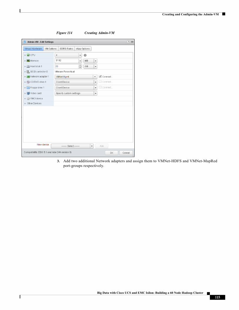
Creating and Configuring the Admin-VM
Figure 114 Creating Admin-VM
3. Add two additional Network adapters and assign them to VMNet-HDFS and VMNet-MapRed port-groups respectively.
115Big Data with Cisco UCS and EMC Isilon: Building a 60 Node Hadoop Cluster
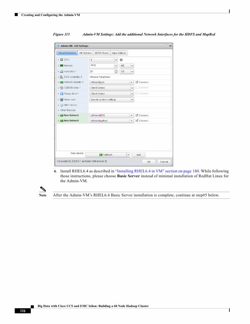
Creating and Configuring the Admin-VM
Figure 115 Admin-VM Settings: Add the additional Network Interfaces for the HDFS and MapRed
4. Install RHEL6.4 as described in “Installing RHEL6.4 in VM” section on page 180. While following those instructions, please choose Basic Server instead of minimal installation of RedHat Linux for the Admin-VM.
Note After the Admin-VM’s RHEL6.4 Basic Server installation is complete, continue at step#5 below.
116Big Data with Cisco UCS and EMC Isilon: Building a 60 Node Hadoop Cluster
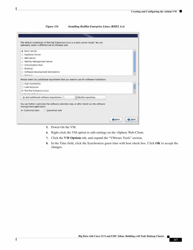
Creating and Configuring the Admin-VM
Figure 116 Installing RedHat Enterprise Linux (RHEL 6.4)
5. Power-On the VM.
6. Right-click the VM option to edit settings on the vSphere Web-Client.
7. Click the VM Options tab, and expand the “VMware Tools” section.
8. In the Time field, click the Synchronize guest time with host check box. Click OK to accept the changes.
117Big Data with Cisco UCS and EMC Isilon: Building a 60 Node Hadoop Cluster
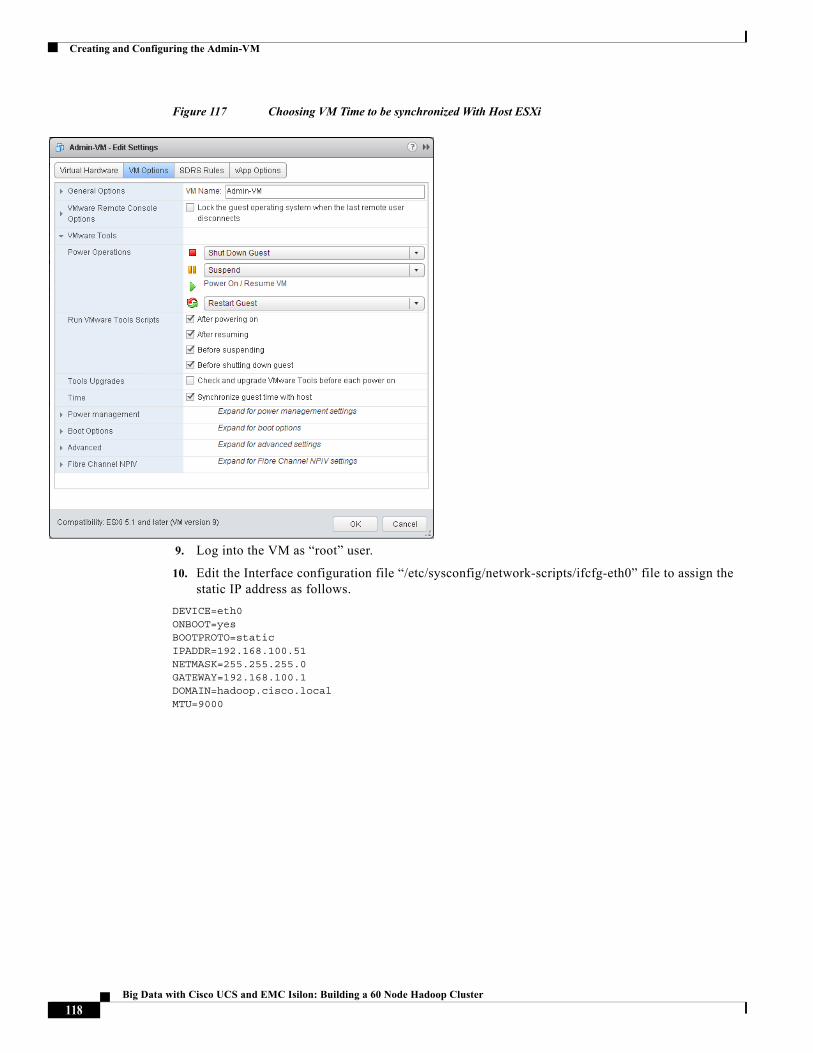
Creating and Configuring the Admin-VM
Figure 117 Choosing VM Time to be synchronized With Host ESXi
9. Log into the VM as “root” user.
10. Edit the Interface configuration file “/etc/sysconfig/network-scripts/ifcfg-eth0” file to assign the static IP address as follows.
DEVICE=eth0ONBOOT=yesBOOTPROTO=staticIPADDR=192.168.100.51NETMASK=255.255.255.0GATEWAY=192.168.100.1DOMAIN=hadoop.cisco.localMTU=9000
118Big Data with Cisco UCS and EMC Isilon: Building a 60 Node Hadoop Cluster
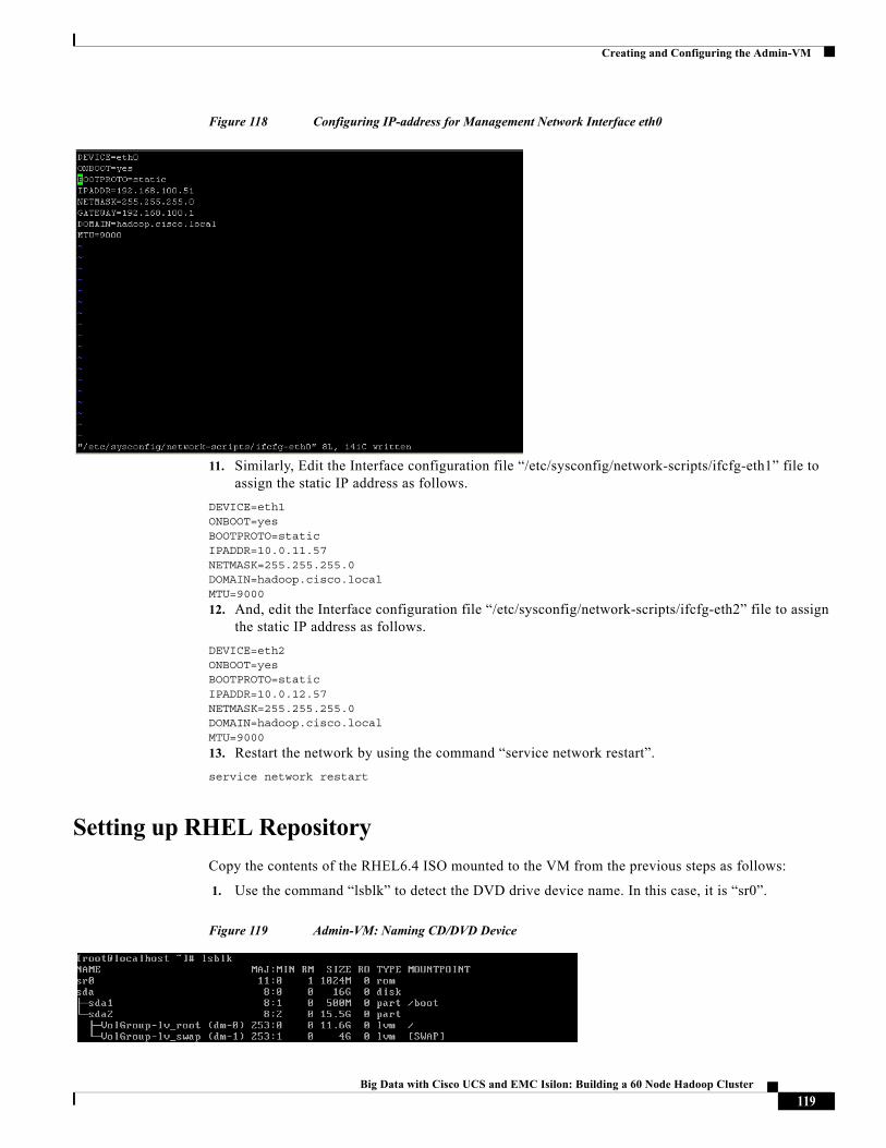
Creating and Configuring the Admin-VM
Figure 118 Configuring IP-address for Management Network Interface eth0
11. Similarly, Edit the Interface configuration file “/etc/sysconfig/network-scripts/ifcfg-eth1” file to assign the static IP address as follows.
DEVICE=eth1ONBOOT=yesBOOTPROTO=staticIPADDR=10.0.11.57NETMASK=255.255.255.0DOMAIN=hadoop.cisco.localMTU=9000
12. And, edit the Interface configuration file “/etc/sysconfig/network-scripts/ifcfg-eth2” file to assign the static IP address as follows.
DEVICE=eth2ONBOOT=yesBOOTPROTO=staticIPADDR=10.0.12.57NETMASK=255.255.255.0DOMAIN=hadoop.cisco.localMTU=9000
13. Restart the network by using the command “service network restart”.
service network restart
Setting up RHEL Repository
Copy the contents of the RHEL6.4 ISO mounted to the VM from the previous steps as follows:
1. Use the command “lsblk” to detect the DVD drive device name. In this case, it is “sr0”.
Figure 119 Admin-VM: Naming CD/DVD Device
119Big Data with Cisco UCS and EMC Isilon: Building a 60 Node Hadoop Cluster
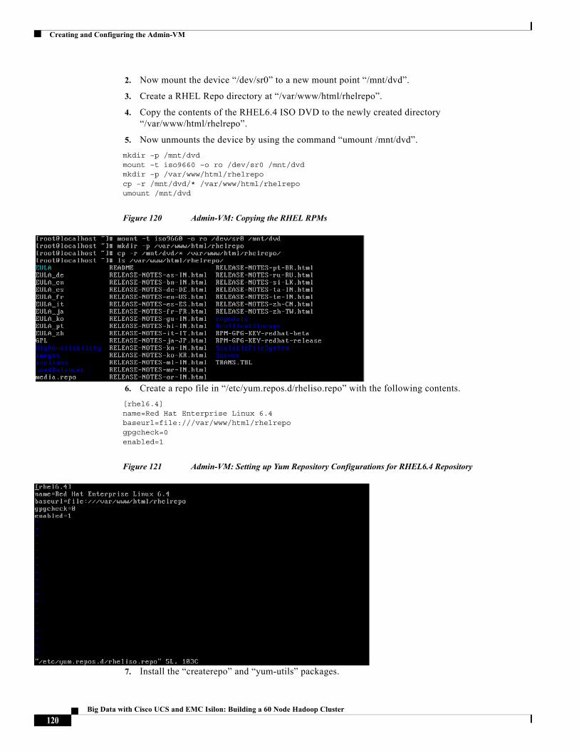
Creating and Configuring the Admin-VM
2. Now mount the device “/dev/sr0” to a new mount point “/mnt/dvd”.
3. Create a RHEL Repo directory at “/var/www/html/rhelrepo”.
4. Copy the contents of the RHEL6.4 ISO DVD to the newly created directory “/var/www/html/rhelrepo”.
5. Now unmounts the device by using the command “umount /mnt/dvd”.
mkdir –p /mnt/dvdmount –t iso9660 –o ro /dev/sr0 /mnt/dvdmkdir –p /var/www/html/rhelrepocp –r /mnt/dvd/* /var/www/html/rhelrepoumount /mnt/dvd
Figure 120 Admin-VM: Copying the RHEL RPMs
6. Create a repo file in “/etc/yum.repos.d/rheliso.repo” with the following contents.
[rhel6.4]name=Red Hat Enterprise Linux 6.4baseurl=file:///var/www/html/rhelrepogpgcheck=0enabled=1
Figure 121 Admin-VM: Setting up Yum Repository Configurations for RHEL6.4 Repository
7. Install the “createrepo” and “yum-utils” packages.
120Big Data with Cisco UCS and EMC Isilon: Building a 60 Node Hadoop Cluster
Creating and Configuring the Admin-VM
yum install createrepo yum-utils
Figure 122 Installing Yum Tools
8. Run “createrepo command in the directory “/var/www/html/rhelrepo”.
cd /var/www/html/rhelrepocreaterepo .
9. Now the RHEL repository is ready. You may optionally create a repo file “/etc/yum.repos.d/rheliso.repo” with the following repository contents to the RHEL6.4-Template so that all the VMs of the Hadoop-Cluster automatically get access to a local RHEL-repository.
[rhel6.4]name=Red Hat Enterprise Linux 6.4baseurl= http://192.168.100.51/rhelrepogpgcheck=0enabled=1
Assign Hostname Admin-VM
The Admin-VM’s Management IP-address is 192.168.100.51. Assign a hostname (FQDN) for this VM. We used the name “admin-vm.hadoop.cisco.com”. Use the command “hostname” to set the FQDN.
hostname admin-vm.hadoop.cisco.local
Figure 123 Assigning Hostname
121Big Data with Cisco UCS and EMC Isilon: Building a 60 Node Hadoop Cluster
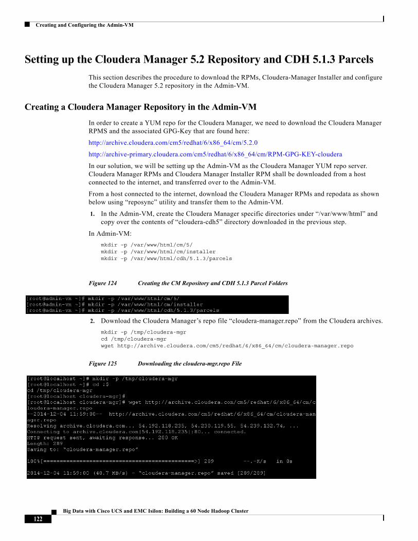
Creating and Configuring the Admin-VM
Setting up the Cloudera Manager 5.2 Repository and CDH 5.1.3 Parcels
This section describes the procedure to download the RPMs, Cloudera-Manager Installer and configure the Cloudera Manager 5.2 repository in the Admin-VM.
Creating a Cloudera Manager Repository in the Admin-VM
In order to create a YUM repo for the Cloudera Manager, we need to download the Cloudera Manager RPMS and the associated GPG-Key that are found here:
http://archive.cloudera.com/cm5/redhat/6/x86_64/cm/5.2.0
http://archive-primary.cloudera.com/cm5/redhat/6/x86_64/cm/RPM-GPG-KEY-cloudera
In our solution, we will be setting up the Admin-VM as the Cloudera Manager YUM repo server. Cloudera Manager RPMs and Cloudera Manager Installer RPM shall be downloaded from a host connected to the internet, and transferred over to the Admin-VM.
From a host connected to the internet, download the Cloudera Manager RPMs and repodata as shown below using “reposync” utility and transfer them to the Admin-VM.
1. In the Admin-VM, create the Cloudera Manager specific directories under “/var/www/html” and copy over the contents of “cloudera-cdh5” directory downloaded in the previous step.
In Admin-VM:
mkdir –p /var/www/html/cm/5/mkdir –p /var/www/html/cm/installermkdir –p /var/www/html/cdh/5.1.3/parcels
Figure 124 Creating the CM Repository and CDH 5.1.3 Parcel Folders
2. Download the Cloudera Manager’s repo file “cloudera-manager.repo” from the Cloudera archives.
mkdir –p /tmp/cloudera-mgrcd /tmp/cloudera-mgrwget http://archive.cloudera.com/cm5/redhat/6/x86_64/cm/cloudera-manager.repo
Figure 125 Downloading the cloudera-mgr.repo File
122Big Data with Cisco UCS and EMC Isilon: Building a 60 Node Hadoop Cluster
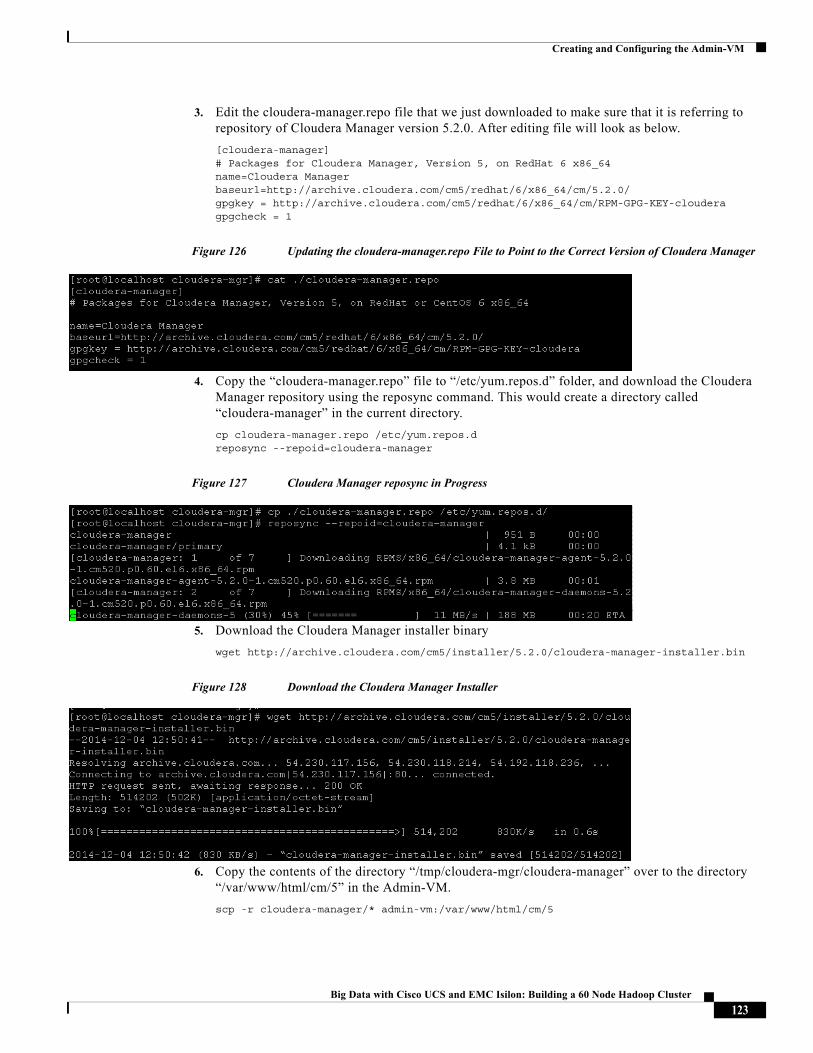
Creating and Configuring the Admin-VM
3. Edit the cloudera-manager.repo file that we just downloaded to make sure that it is referring to repository of Cloudera Manager version 5.2.0. After editing file will look as below.
[cloudera-manager]# Packages for Cloudera Manager, Version 5, on RedHat 6 x86_64 name=Cloudera Managerbaseurl=http://archive.cloudera.com/cm5/redhat/6/x86_64/cm/5.2.0/gpgkey = http://archive.cloudera.com/cm5/redhat/6/x86_64/cm/RPM-GPG-KEY-clouderagpgcheck = 1
Figure 126 Updating the cloudera-manager.repo File to Point to the Correct Version of Cloudera Manager
4. Copy the “cloudera-manager.repo” file to “/etc/yum.repos.d” folder, and download the Cloudera Manager repository using the reposync command. This would create a directory called “cloudera-manager” in the current directory.
cp cloudera-manager.repo /etc/yum.repos.dreposync --repoid=cloudera-manager
Figure 127 Cloudera Manager reposync in Progress
5. Download the Cloudera Manager installer binary
wget http://archive.cloudera.com/cm5/installer/5.2.0/cloudera-manager-installer.bin
Figure 128 Download the Cloudera Manager Installer
6. Copy the contents of the directory “/tmp/cloudera-mgr/cloudera-manager” over to the directory “/var/www/html/cm/5” in the Admin-VM.
scp -r cloudera-manager/* admin-vm:/var/www/html/cm/5
123Big Data with Cisco UCS and EMC Isilon: Building a 60 Node Hadoop Cluster
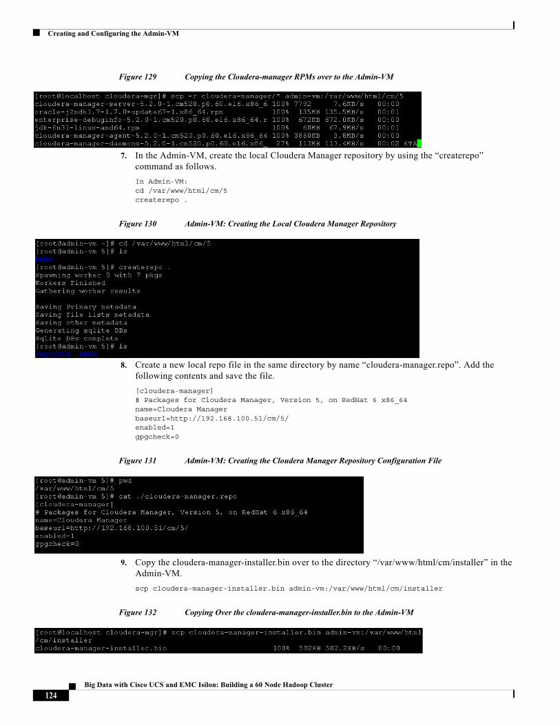
Creating and Configuring the Admin-VM
Figure 129 Copying the Cloudera-manager RPMs over to the Admin-VM
7. In the Admin-VM, create the local Cloudera Manager repository by using the “createrepo” command as follows.
In Admin-VM:cd /var/www/html/cm/5createrepo .
Figure 130 Admin-VM: Creating the Local Cloudera Manager Repository
8. Create a new local repo file in the same directory by name “cloudera-manager.repo”. Add the following contents and save the file.
[cloudera-manager]# Packages for Cloudera Manager, Version 5, on RedHat 6 x86_64 name=Cloudera Manager baseurl=http://192.168.100.51/cm/5/enabled=1gpgcheck=0
Figure 131 Admin-VM: Creating the Cloudera Manager Repository Configuration File
9. Copy the cloudera-manager-installer.bin over to the directory “/var/www/html/cm/installer” in the Admin-VM.
scp cloudera-manager-installer.bin admin-vm:/var/www/html/cm/installer
Figure 132 Copying Over the cloudera-manager-installer.bin to the Admin-VM
124Big Data with Cisco UCS and EMC Isilon: Building a 60 Node Hadoop Cluster
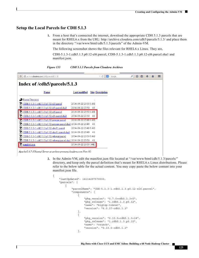
Creating and Configuring the Admin-VM
Setup the Local Parcels for CDH 5.1.3
1. From a host that’s connected the internet, download the appropriate CDH 5.1.3 parcels that are meant for RHEL6.x from the URL: http://archive.cloudera.com/cdh5/parcels/5.1.3/ and place them in the directory “/var/www/html/cdh/5.1.3/parcels” of the Admin-VM.
The following screenshot shows the files relevant for RHEL6.x Linux. They are,
CDH-5.1.3-1.cdh5.1.3.p0.12-el6.parcel, CDH-5.1.3-1.cdh5.1.3.p0.12-el6.parcel.sha1 and manifest.json.
Figure 133 CDH 5.1.3 Parcels from Cloudera Archives
2. In the Admin-VM, edit the manifest.json file located at “/var/www/html/cdh/5.1.3/parcels/” directory, and keep only the parcel definition that’s meant for RHEL6.x Linux distributions. Please refer to the below table for the actual content. You may copy paste the below content into your manifest.json file.
{ "lastUpdated": 14114297570000, "parcels": [ { "parcelName": "CDH-5.1.3-1.cdh5.1.3.p0.12-el6.parcel", "components": [ { "pkg_version": "0.7.0+cdh5.1.3+0", "pkg_release": "1.cdh5.1.3.p0.12", "name": "bigtop-tomcat", "version": "6.0.37-cdh5.1.3" }, { "pkg_version": "0.10.0+cdh5.1.3+18", "pkg_release": "1.cdh5.1.3.p0.10", "name": "crunch", "version": "0.10.0-cdh5.1.3" },
125Big Data with Cisco UCS and EMC Isilon: Building a 60 Node Hadoop Cluster
Creating and Configuring the Admin-VM
{ "pkg_version": "1.5.0+cdh5.1.3+15", "pkg_release": "1.cdh5.1.3.p0.9", "name": "flume-ng", "version": "1.5.0-cdh5.1.3" }, { "pkg_version": "2.3.0+cdh5.1.3+824", "pkg_release": "1.cdh5.1.3.p0.13", "name": "hadoop-0.20-mapreduce", "version": "2.3.0-cdh5.1.3" }, { "pkg_version": "2.3.0+cdh5.1.3+824", "pkg_release": "1.cdh5.1.3.p0.13", "name": "hadoop-hdfs", "version": "2.3.0-cdh5.1.3" }, { "pkg_version": "2.3.0+cdh5.1.3+824", "pkg_release": "1.cdh5.1.3.p0.13", "name": "hadoop-httpfs", "version": "2.3.0-cdh5.1.3" }, { "pkg_version": "2.3.0+cdh5.1.3+824", "pkg_release": "1.cdh5.1.3.p0.13", "name": "hadoop-mapreduce", "version": "2.3.0-cdh5.1.3" }, { "pkg_version": "2.3.0+cdh5.1.3+824", "pkg_release": "1.cdh5.1.3.p0.13", "name": "hadoop-yarn", "version": "2.3.0-cdh5.1.3" }, { "pkg_version": "2.3.0+cdh5.1.3+824", "pkg_release": "1.cdh5.1.3.p0.13", "name": "hadoop", "version": "2.3.0-cdh5.1.3" }, { "pkg_version": "1.5+cdh5.1.3+16", "pkg_release": "1.cdh5.1.3.p0.9", "name": "hbase-solr", "version": "1.5-cdh5.1.3" }, { "pkg_version": "0.98.1+cdh5.1.3+82", "pkg_release": "1.cdh5.1.3.p0.12", "name": "hbase", "version": "0.98.1-cdh5.1.3" }, { "pkg_version": "0.12.0+cdh5.1.3+381", "pkg_release": "1.cdh5.1.3.p0.11", "name": "hive-hcatalog", "version": "0.12.0-cdh5.1.3" }, { "pkg_version": "0.12.0+cdh5.1.3+381", "pkg_release": "1.cdh5.1.3.p0.11", "name": "hive",
126Big Data with Cisco UCS and EMC Isilon: Building a 60 Node Hadoop Cluster
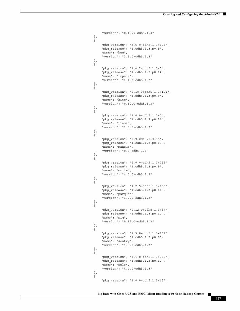
Creating and Configuring the Admin-VM
"version": "0.12.0-cdh5.1.3" }, { "pkg_version": "3.6.0+cdh5.1.3+108", "pkg_release": "1.cdh5.1.3.p0.9", "name": "hue", "version": "3.6.0-cdh5.1.3" }, { "pkg_version": "1.4.2+cdh5.1.3+0", "pkg_release": "1.cdh5.1.3.p0.14", "name": "impala", "version": "1.4.2-cdh5.1.3" }, { "pkg_version": "0.10.0+cdh5.1.3+124", "pkg_release": "1.cdh5.1.3.p0.9", "name": "kite", "version": "0.10.0-cdh5.1.3" }, { "pkg_version": "1.0.0+cdh5.1.3+0", "pkg_release": "1.cdh5.1.3.p0.12", "name": "llama", "version": "1.0.0-cdh5.1.3" }, { "pkg_version": "0.9+cdh5.1.3+15", "pkg_release": "1.cdh5.1.3.p0.13", "name": "mahout", "version": "0.9-cdh5.1.3" }, { "pkg_version": "4.0.0+cdh5.1.3+255", "pkg_release": "1.cdh5.1.3.p0.9", "name": "oozie", "version": "4.0.0-cdh5.1.3" }, { "pkg_version": "1.2.5+cdh5.1.3+138", "pkg_release": "1.cdh5.1.3.p0.11", "name": "parquet", "version": "1.2.5-cdh5.1.3" }, { "pkg_version": "0.12.0+cdh5.1.3+37", "pkg_release": "1.cdh5.1.3.p0.10", "name": "pig", "version": "0.12.0-cdh5.1.3" }, { "pkg_version": "1.3.0+cdh5.1.3+162", "pkg_release": "1.cdh5.1.3.p0.9", "name": "sentry", "version": "1.3.0-cdh5.1.3" }, { "pkg_version": "4.4.0+cdh5.1.3+235", "pkg_release": "1.cdh5.1.3.p0.10", "name": "solr", "version": "4.4.0-cdh5.1.3" }, { "pkg_version": "1.0.0+cdh5.1.3+45",
127Big Data with Cisco UCS and EMC Isilon: Building a 60 Node Hadoop Cluster
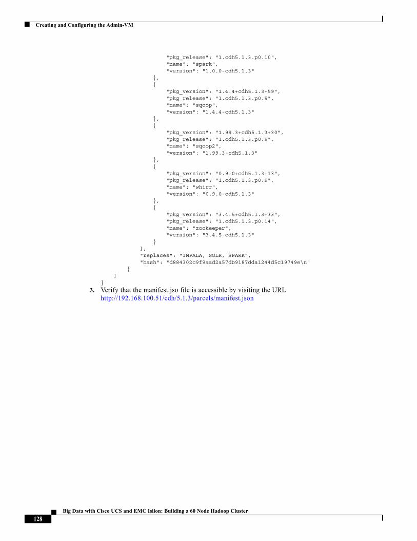
Creating and Configuring the Admin-VM
"pkg_release": "1.cdh5.1.3.p0.10", "name": "spark", "version": "1.0.0-cdh5.1.3" }, { "pkg_version": "1.4.4+cdh5.1.3+59", "pkg_release": "1.cdh5.1.3.p0.9", "name": "sqoop", "version": "1.4.4-cdh5.1.3" }, { "pkg_version": "1.99.3+cdh5.1.3+30", "pkg_release": "1.cdh5.1.3.p0.9", "name": "sqoop2", "version": "1.99.3-cdh5.1.3" }, { "pkg_version": "0.9.0+cdh5.1.3+13", "pkg_release": "1.cdh5.1.3.p0.9", "name": "whirr", "version": "0.9.0-cdh5.1.3" }, { "pkg_version": "3.4.5+cdh5.1.3+33", "pkg_release": "1.cdh5.1.3.p0.14", "name": "zookeeper", "version": "3.4.5-cdh5.1.3" } ], "replaces": "IMPALA, SOLR, SPARK", "hash": "d884302c9f9aad2a57db9187dda1244d5c19749e\n" } ]}
3. Verify that the manifest.jso file is accessible by visiting the URL http://192.168.100.51/cdh/5.1.3/parcels/manifest.json
128Big Data with Cisco UCS and EMC Isilon: Building a 60 Node Hadoop Cluster
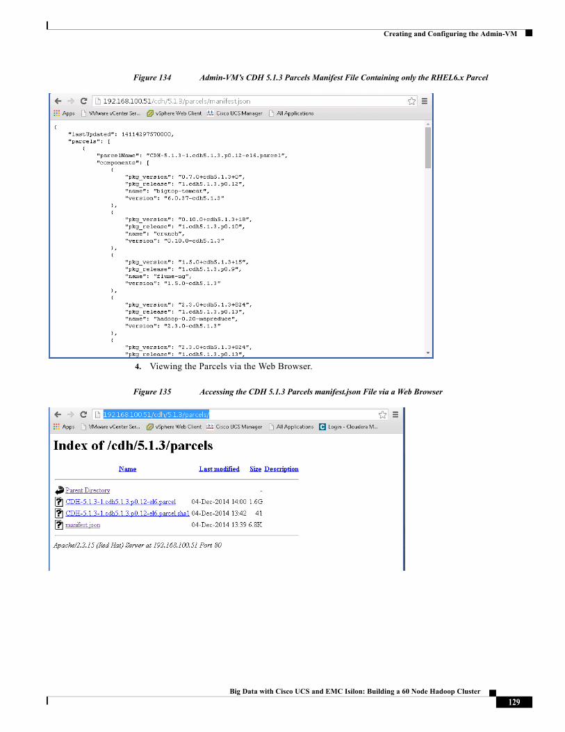
Creating and Configuring the Admin-VM
Figure 134 Admin-VM’s CDH 5.1.3 Parcels Manifest File Containing only the RHEL6.x Parcel
4. Viewing the Parcels via the Web Browser.
Figure 135 Accessing the CDH 5.1.3 Parcels manifest.json File via a Web Browser
129Big Data with Cisco UCS and EMC Isilon: Building a 60 Node Hadoop Cluster
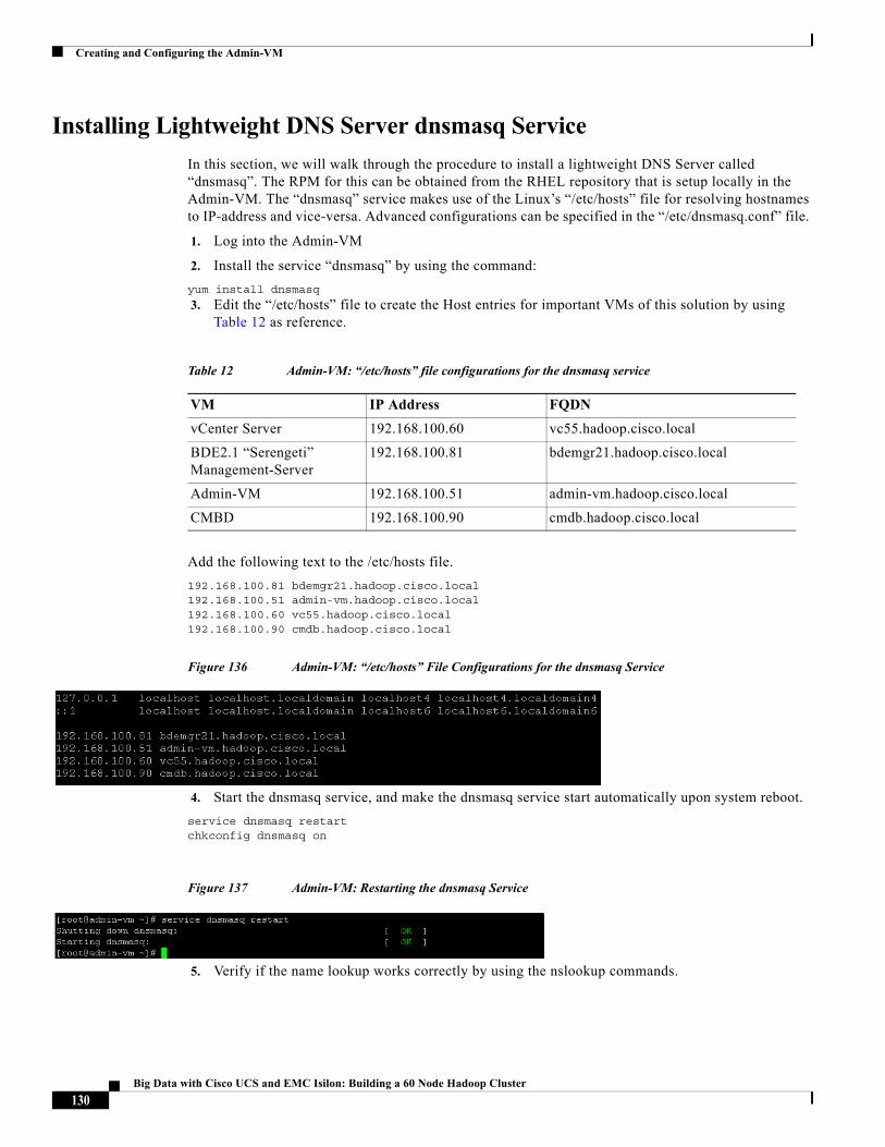
Creating and Configuring the Admin-VM
Installing Lightweight DNS Server dnsmasq Service
In this section, we will walk through the procedure to install a lightweight DNS Server called “dnsmasq”. The RPM for this can be obtained from the RHEL repository that is setup locally in the Admin-VM. The “dnsmasq” service makes use of the Linux’s “/etc/hosts” file for resolving hostnames to IP-address and vice-versa. Advanced configurations can be specified in the “/etc/dnsmasq.conf” file.
1. Log into the Admin-VM
2. Install the service “dnsmasq” by using the command:
yum install dnsmasq
3. Edit the “/etc/hosts” file to create the Host entries for important VMs of this solution by using Table 12 as reference.
Add the following text to the /etc/hosts file.
192.168.100.81 bdemgr21.hadoop.cisco.local192.168.100.51 admin-vm.hadoop.cisco.local192.168.100.60 vc55.hadoop.cisco.local192.168.100.90 cmdb.hadoop.cisco.local
Figure 136 Admin-VM: “/etc/hosts” File Configurations for the dnsmasq Service
4. Start the dnsmasq service, and make the dnsmasq service start automatically upon system reboot.
service dnsmasq restartchkconfig dnsmasq on
Figure 137 Admin-VM: Restarting the dnsmasq Service
5. Verify if the name lookup works correctly by using the nslookup commands.
Table 12 Admin-VM: “/etc/hosts” file configurations for the dnsmasq service
VM IP Address FQDN
vCenter Server 192.168.100.60 vc55.hadoop.cisco.local
BDE2.1 “Serengeti” Management-Server
192.168.100.81 bdemgr21.hadoop.cisco.local
Admin-VM 192.168.100.51 admin-vm.hadoop.cisco.local
CMBD 192.168.100.90 cmdb.hadoop.cisco.local
130Big Data with Cisco UCS and EMC Isilon: Building a 60 Node Hadoop Cluster
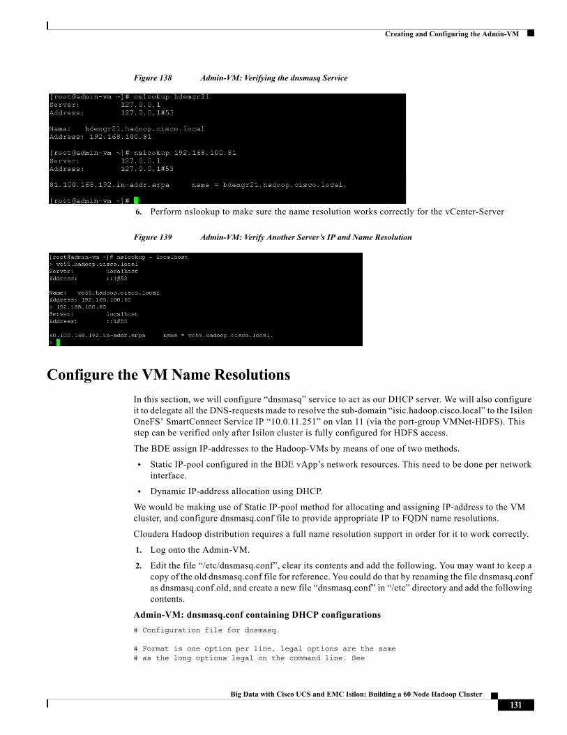
Creating and Configuring the Admin-VM
Figure 138 Admin-VM: Verifying the dnsmasq Service
6. Perform nslookup to make sure the name resolution works correctly for the vCenter-Server
Figure 139 Admin-VM: Verify Another Server’s IP and Name Resolution
Configure the VM Name Resolutions
In this section, we will configure “dnsmasq” service to act as our DHCP server. We will also configure it to delegate all the DNS-requests made to resolve the sub-domain “isic.hadoop.cisco.local” to the Isilon OneFS’ SmartConnect Service IP “10.0.11.251” on vlan 11 (via the port-group VMNet-HDFS). This step can be verified only after Isilon cluster is fully configured for HDFS access.
The BDE assign IP-addresses to the Hadoop-VMs by means of one of two methods.
• Static IP-pool configured in the BDE vApp’s network resources. This need to be done per network interface.
• Dynamic IP-address allocation using DHCP.
We would be making use of Static IP-pool method for allocating and assigning IP-address to the VM cluster, and configure dnsmasq.conf file to provide appropriate IP to FQDN name resolutions.
Cloudera Hadoop distribution requires a full name resolution support in order for it to work correctly.
1. Log onto the Admin-VM.
2. Edit the file “/etc/dnsmasq.conf”, clear its contents and add the following. You may want to keep a copy of the old dnsmasq.conf file for reference. You could do that by renaming the file dnsmasq.conf as dnsmasq.conf.old, and create a new file “dnsmasq.conf” in “/etc” directory and add the following contents.
Admin-VM: dnsmasq.conf containing DHCP configurations
# Configuration file for dnsmasq.
# Format is one option per line, legal options are the same# as the long options legal on the command line. See
131Big Data with Cisco UCS and EMC Isilon: Building a 60 Node Hadoop Cluster
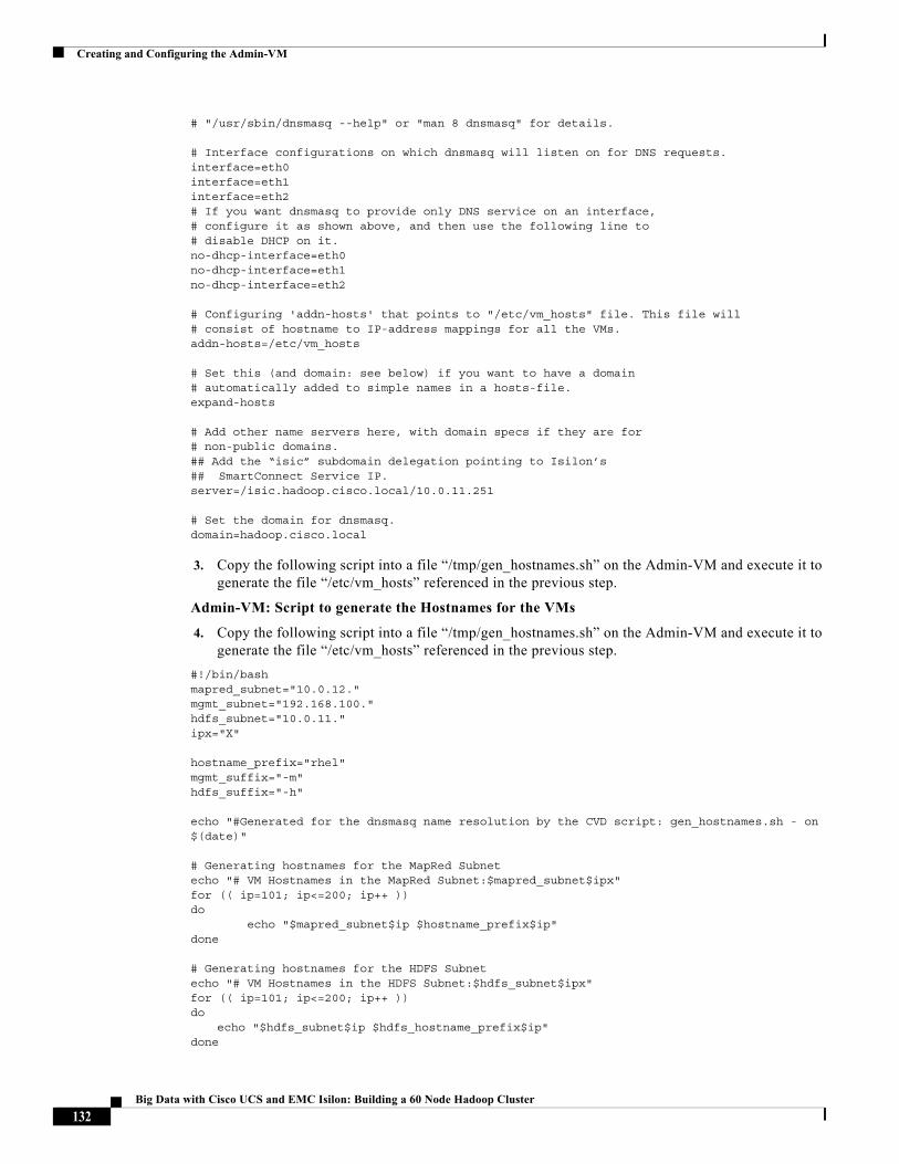
Creating and Configuring the Admin-VM
# "/usr/sbin/dnsmasq --help" or "man 8 dnsmasq" for details.
# Interface configurations on which dnsmasq will listen on for DNS requests.interface=eth0interface=eth1interface=eth2# If you want dnsmasq to provide only DNS service on an interface,# configure it as shown above, and then use the following line to# disable DHCP on it.no-dhcp-interface=eth0no-dhcp-interface=eth1no-dhcp-interface=eth2
# Configuring 'addn-hosts' that points to "/etc/vm_hosts" file. This file will# consist of hostname to IP-address mappings for all the VMs.addn-hosts=/etc/vm_hosts
# Set this (and domain: see below) if you want to have a domain# automatically added to simple names in a hosts-file.expand-hosts
# Add other name servers here, with domain specs if they are for# non-public domains.## Add the “isic” subdomain delegation pointing to Isilon’s ## SmartConnect Service IP.server=/isic.hadoop.cisco.local/10.0.11.251
# Set the domain for dnsmasq.domain=hadoop.cisco.local
3. Copy the following script into a file “/tmp/gen_hostnames.sh” on the Admin-VM and execute it to generate the file “/etc/vm_hosts” referenced in the previous step.
Admin-VM: Script to generate the Hostnames for the VMs
4. Copy the following script into a file “/tmp/gen_hostnames.sh” on the Admin-VM and execute it to generate the file “/etc/vm_hosts” referenced in the previous step.
#!/bin/bashmapred_subnet="10.0.12."mgmt_subnet="192.168.100."hdfs_subnet="10.0.11."ipx="X"
hostname_prefix="rhel"mgmt_suffix="-m"hdfs_suffix="-h"
echo "#Generated for the dnsmasq name resolution by the CVD script: gen_hostnames.sh - on $(date)"
# Generating hostnames for the MapRed Subnetecho "# VM Hostnames in the MapRed Subnet:$mapred_subnet$ipx"for (( ip=101; ip<=200; ip++ ))do echo "$mapred_subnet$ip $hostname_prefix$ip"done
# Generating hostnames for the HDFS Subnetecho "# VM Hostnames in the HDFS Subnet:$hdfs_subnet$ipx"for (( ip=101; ip<=200; ip++ ))do
echo "$hdfs_subnet$ip $hdfs_hostname_prefix$ip"done
132Big Data with Cisco UCS and EMC Isilon: Building a 60 Node Hadoop Cluster
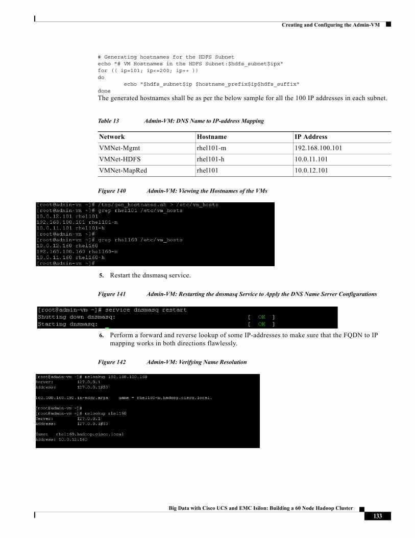
Creating and Configuring the Admin-VM
# Generating hostnames for the HDFS Subnetecho "# VM Hostnames in the HDFS Subnet:$hdfs_subnet$ipx"for (( ip=101; ip<=200; ip++ ))do echo "$hdfs_subnet$ip $hostname_prefix$ip$hdfs_suffix"done
The generated hostnames shall be as per the below sample for all the 100 IP addresses in each subnet.
Figure 140 Admin-VM: Viewing the Hostnames of the VMs
5. Restart the dnsmasq service.
Figure 141 Admin-VM: Restarting the dnsmasq Service to Apply the DNS Name Server Configurations
6. Perform a forward and reverse lookup of some IP-addresses to make sure that the FQDN to IP mapping works in both directions flawlessly.
Figure 142 Admin-VM: Verifying Name Resolution
Table 13 Admin-VM: DNS Name to IP-address Mapping
Network Hostname IP Address
VMNet-Mgmt rhel101-m 192.168.100.101
VMNet-HDFS rhel101-h 10.0.11.101
VMNet-MapRed rhel101 10.0.12.101
133Big Data with Cisco UCS and EMC Isilon: Building a 60 Node Hadoop Cluster
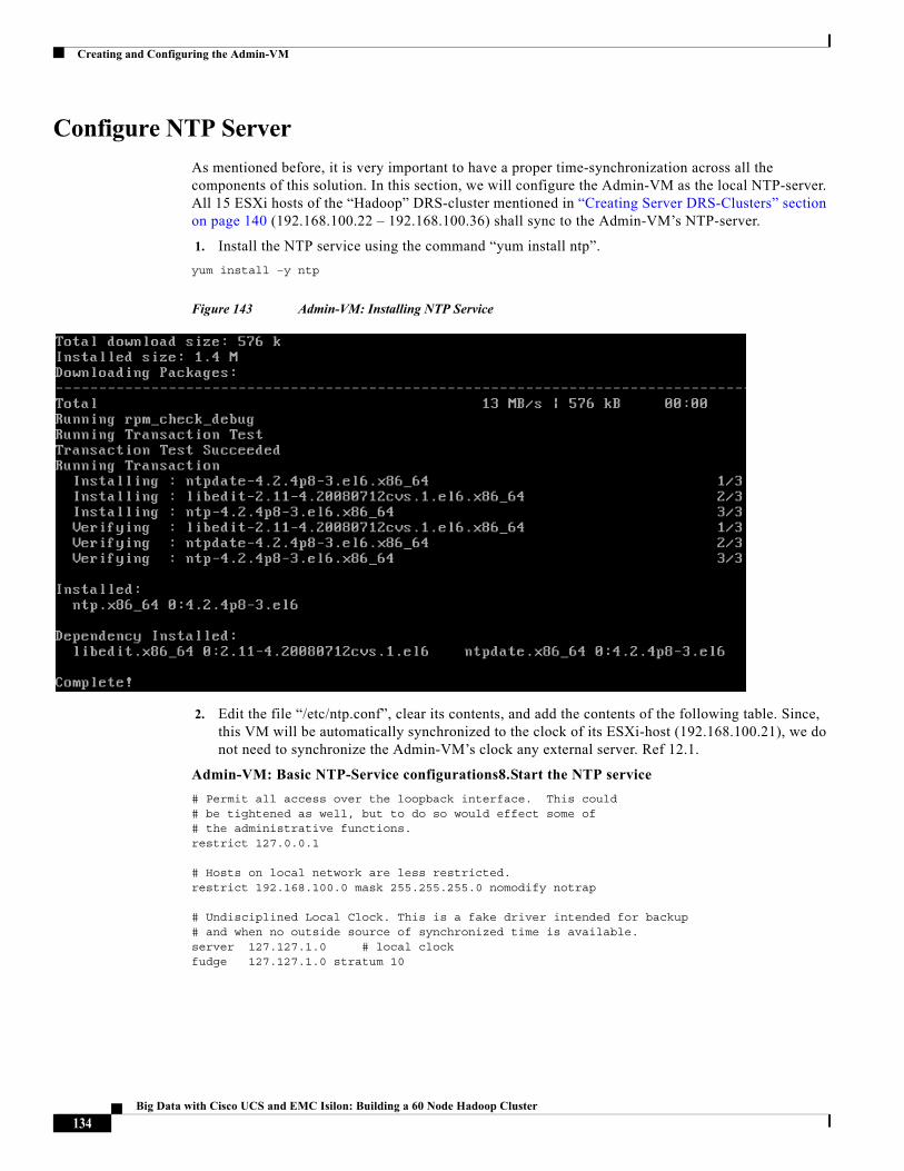
Creating and Configuring the Admin-VM
Configure NTP Server
As mentioned before, it is very important to have a proper time-synchronization across all the components of this solution. In this section, we will configure the Admin-VM as the local NTP-server. All 15 ESXi hosts of the “Hadoop” DRS-cluster mentioned in “Creating Server DRS-Clusters” section on page 140 (192.168.100.22 – 192.168.100.36) shall sync to the Admin-VM’s NTP-server.
1. Install the NTP service using the command “yum install ntp”.
yum install –y ntp
Figure 143 Admin-VM: Installing NTP Service
2. Edit the file “/etc/ntp.conf”, clear its contents, and add the contents of the following table. Since, this VM will be automatically synchronized to the clock of its ESXi-host (192.168.100.21), we do not need to synchronize the Admin-VM’s clock any external server. Ref 12.1.
Admin-VM: Basic NTP-Service configurations8.Start the NTP service
# Permit all access over the loopback interface. This could# be tightened as well, but to do so would effect some of# the administrative functions.restrict 127.0.0.1
# Hosts on local network are less restricted.restrict 192.168.100.0 mask 255.255.255.0 nomodify notrap
# Undisciplined Local Clock. This is a fake driver intended for backup# and when no outside source of synchronized time is available.server 127.127.1.0 # local clockfudge 127.127.1.0 stratum 10
134Big Data with Cisco UCS and EMC Isilon: Building a 60 Node Hadoop Cluster
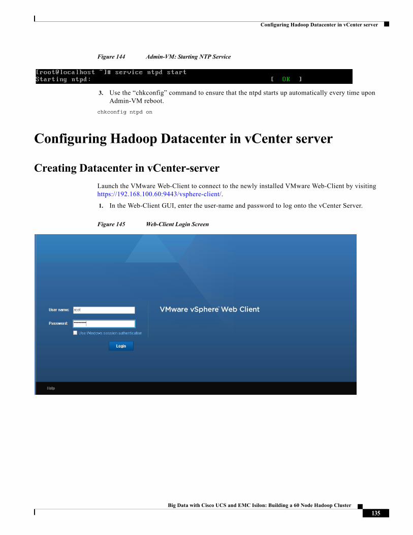
Configuring Hadoop Datacenter in vCenter server
Figure 144 Admin-VM: Starting NTP Service
3. Use the “chkconfig” command to ensure that the ntpd starts up automatically every time upon Admin-VM reboot.
chkconfig ntpd on
Configuring Hadoop Datacenter in vCenter server
Creating Datacenter in vCenter-server
Launch the VMware Web-Client to connect to the newly installed VMware Web-Client by visiting https://192.168.100.60:9443/vsphere-client/.
1. In the Web-Client GUI, enter the user-name and password to log onto the vCenter Server.
Figure 145 Web-Client Login Screen
135Big Data with Cisco UCS and EMC Isilon: Building a 60 Node Hadoop Cluster
Configuring Hadoop Datacenter in vCenter server
Figure 146 vSphere Web-Client vCenter Home-screen
2. From the home screen click vCenter on the navigation pane on the left side.
136Big Data with Cisco UCS and EMC Isilon: Building a 60 Node Hadoop Cluster
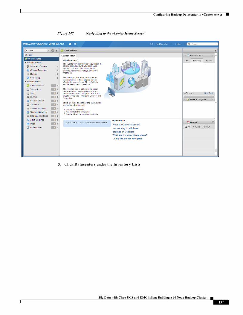
Configuring Hadoop Datacenter in vCenter server
Figure 147 Navigating to the vCenter Home Screen
3. Click Datacenters under the Inventory Lists
137Big Data with Cisco UCS and EMC Isilon: Building a 60 Node Hadoop Cluster
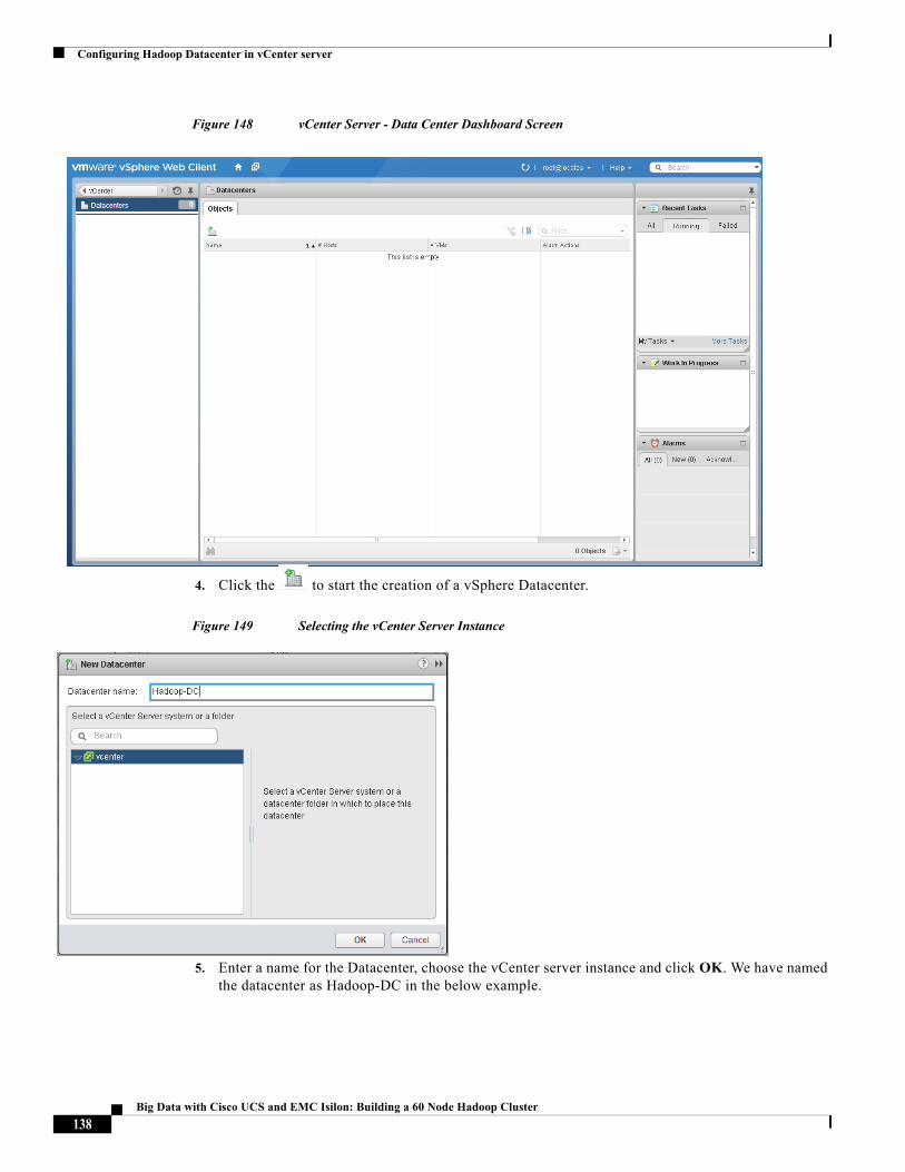
Configuring Hadoop Datacenter in vCenter server
Figure 148 vCenter Server - Data Center Dashboard Screen
4. Click the to start the creation of a vSphere Datacenter.
Figure 149 Selecting the vCenter Server Instance
5. Enter a name for the Datacenter, choose the vCenter server instance and click OK. We have named the datacenter as Hadoop-DC in the below example.
138Big Data with Cisco UCS and EMC Isilon: Building a 60 Node Hadoop Cluster
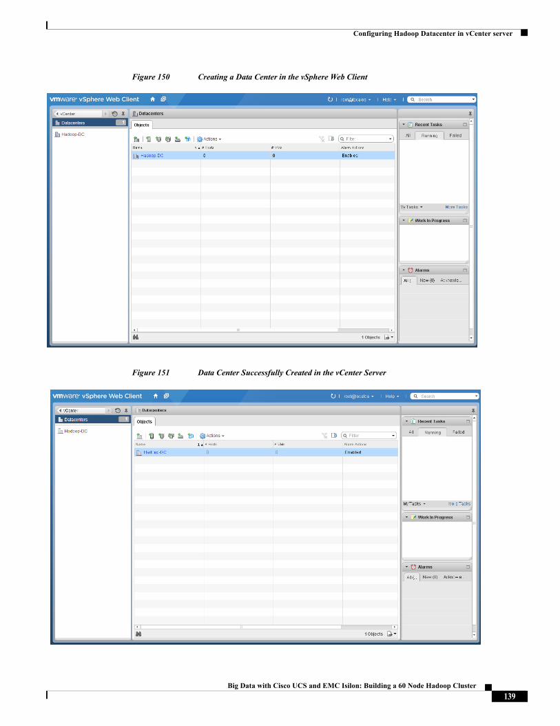
Configuring Hadoop Datacenter in vCenter server
Figure 150 Creating a Data Center in the vSphere Web Client
Figure 151 Data Center Successfully Created in the vCenter Server
139Big Data with Cisco UCS and EMC Isilon: Building a 60 Node Hadoop Cluster
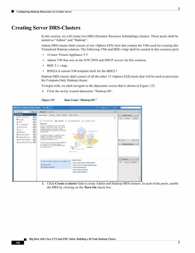
Configuring Hadoop Datacenter in vCenter server
Creating Server DRS-Clusters
In this section, we will create two DRS (Dynamic Resource Scheduling) clusters. Those pools shall be named as “Admin” and “Hadoop”.
Admin DRS-cluster shall consist of one vSphere ESXi host that contain the VMs used for creating this Virtualized Hadoop solution. The following VMs and BDE-vApp shall be created in this resource pool:
• vCenter Virtual-Appliance 5.5
• Admin VM that acts as the NTP, DNS and DHCP servers for this solution.
• BDE 2.1 vApp.
• RHEL6.4 custom VM-template built for the BDE2.1
Hadoop DRS-cluster shall consist of all the other 15 vSphere ESXi hosts that will be used to provision the Compute-Only Hadoop cluster.
To begin with, we shall navigate to the datacenter screen that is shown in Figure 152.
1. Click the newly created datacenter “Hadoop-DC.
Figure 152 Data Center “Hadoop-DC”
2. Click Create a cluster link to create Admin and Hadoop DRS-clusters. In each of the pools, enable the DRS by clicking on the Turn On check box.
140Big Data with Cisco UCS and EMC Isilon: Building a 60 Node Hadoop Cluster
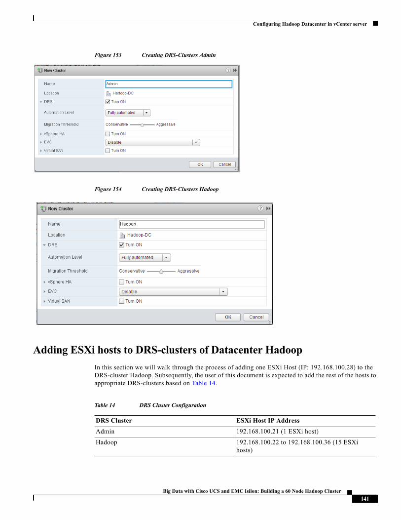
Configuring Hadoop Datacenter in vCenter server
Figure 153 Creating DRS-Clusters Admin
Figure 154 Creating DRS-Clusters Hadoop
Adding ESXi hosts to DRS-clusters of Datacenter Hadoop
In this section we will walk through the process of adding one ESXi Host (IP: 192.168.100.28) to the DRS-cluster Hadoop. Subsequently, the user of this document is expected to add the rest of the hosts to appropriate DRS-clusters based on Table 14.
Table 14 DRS Cluster Configuration
DRS Cluster ESXi Host IP Address
Admin 192.168.100.21 (1 ESXi host)
Hadoop 192.168.100.22 to 192.168.100.36 (15 ESXi hosts)
141Big Data with Cisco UCS and EMC Isilon: Building a 60 Node Hadoop Cluster
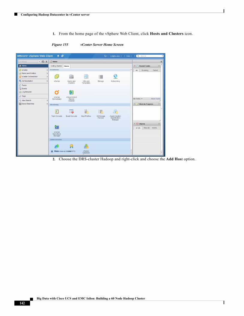
Configuring Hadoop Datacenter in vCenter server
1. From the home page of the vSphere Web Client, click Hosts and Clusters icon.
Figure 155 vCenter Server Home Screen
2. Choose the DRS-cluster Hadoop and right-click and choose the Add Host option.
142Big Data with Cisco UCS and EMC Isilon: Building a 60 Node Hadoop Cluster
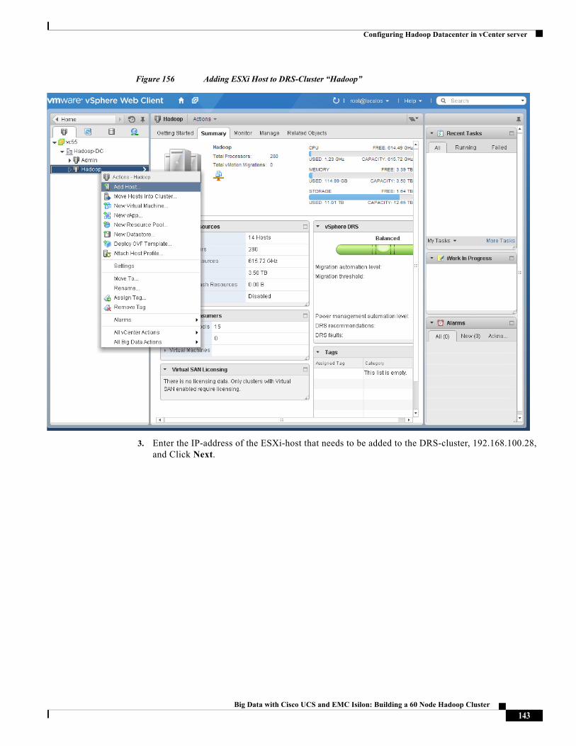
Configuring Hadoop Datacenter in vCenter server
Figure 156 Adding ESXi Host to DRS-Cluster “Hadoop”
3. Enter the IP-address of the ESXi-host that needs to be added to the DRS-cluster, 192.168.100.28, and Click Next.
143Big Data with Cisco UCS and EMC Isilon: Building a 60 Node Hadoop Cluster
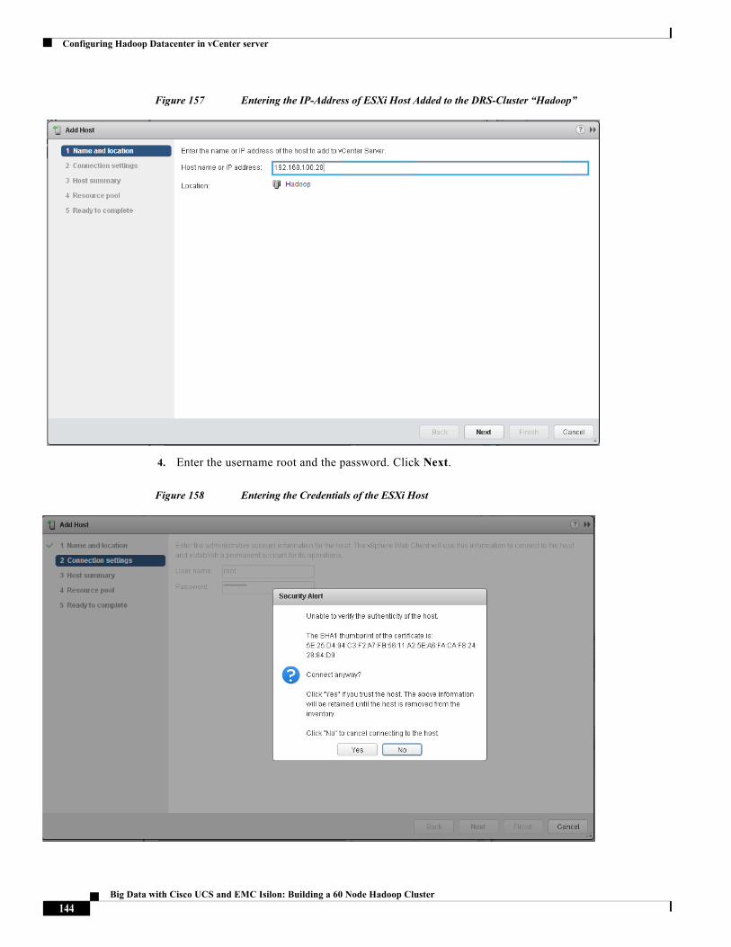
Configuring Hadoop Datacenter in vCenter server
Figure 157 Entering the IP-Address of ESXi Host Added to the DRS-Cluster “Hadoop”
4. Enter the username root and the password. Click Next.
Figure 158 Entering the Credentials of the ESXi Host
144Big Data with Cisco UCS and EMC Isilon: Building a 60 Node Hadoop Cluster
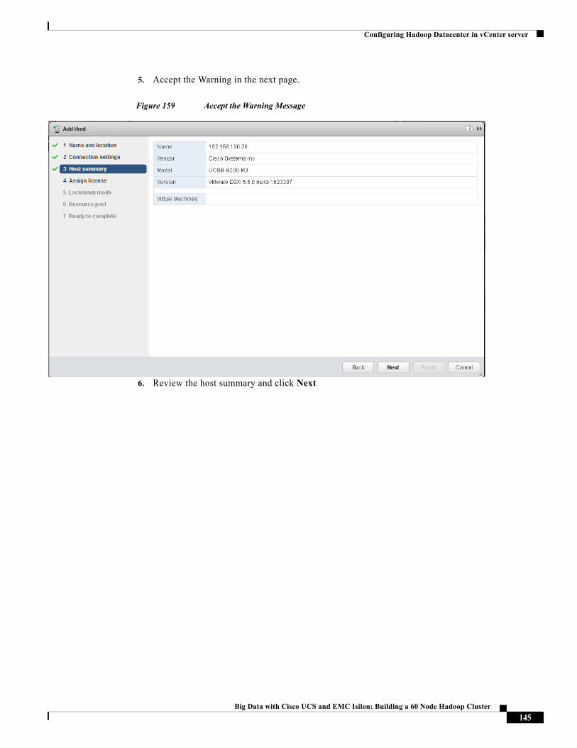
Configuring Hadoop Datacenter in vCenter server
5. Accept the Warning in the next page.
Figure 159 Accept the Warning Message
6. Review the host summary and click Next
145Big Data with Cisco UCS and EMC Isilon: Building a 60 Node Hadoop Cluster
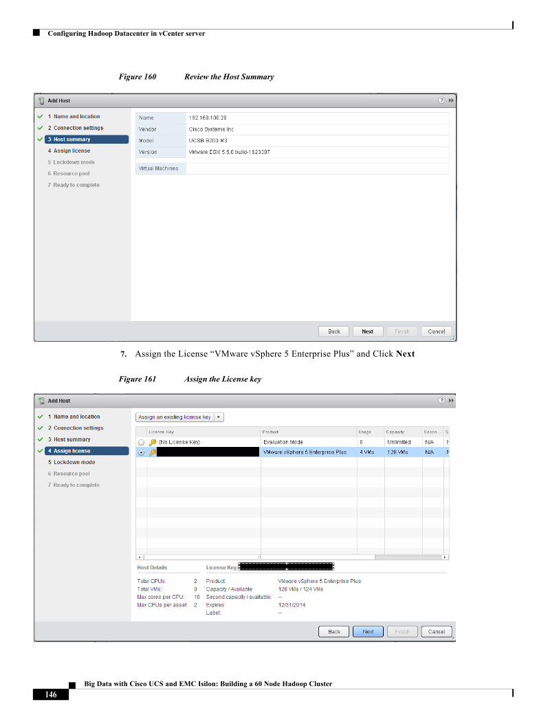
Configuring Hadoop Datacenter in vCenter server
Figure 160 Review the Host Summary
7. Assign the License “VMware vSphere 5 Enterprise Plus” and Click Next
Figure 161 Assign the License key
146Big Data with Cisco UCS and EMC Isilon: Building a 60 Node Hadoop Cluster
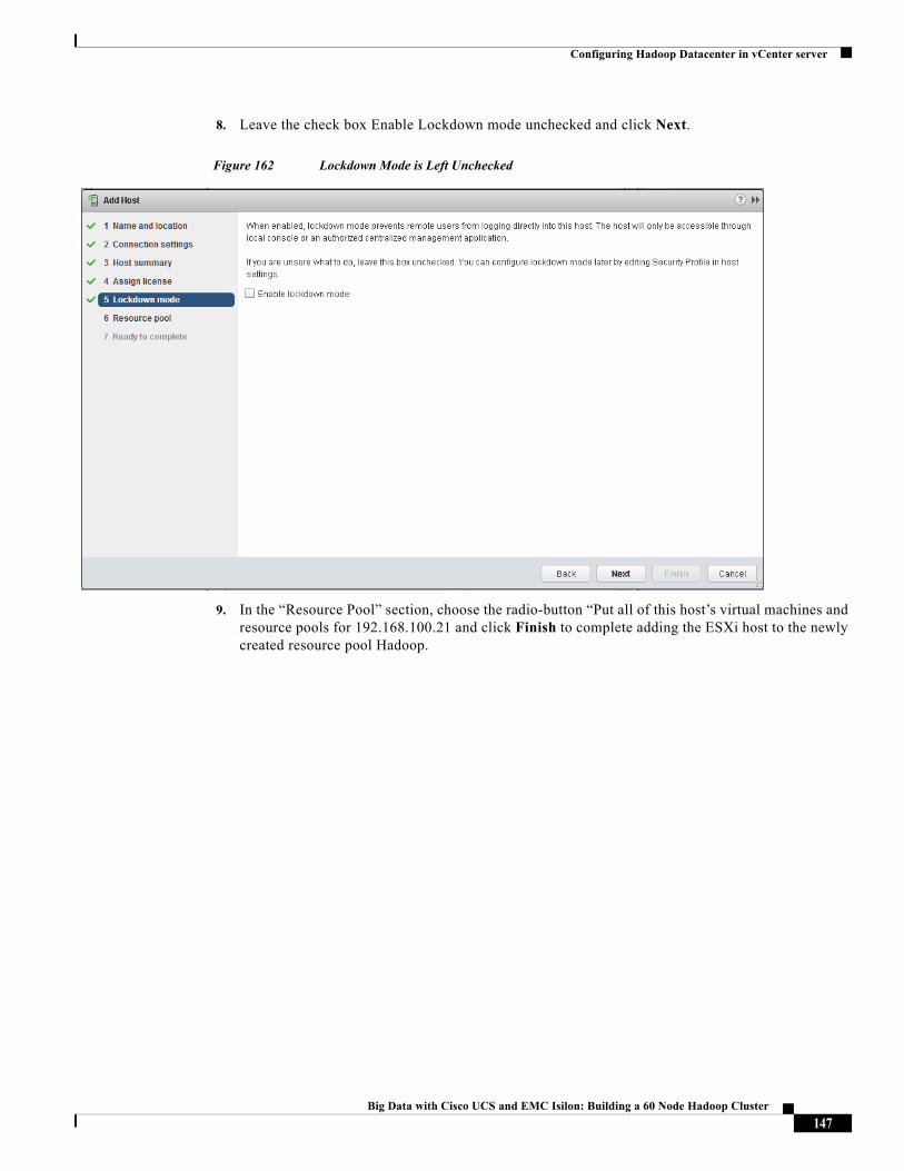
Configuring Hadoop Datacenter in vCenter server
8. Leave the check box Enable Lockdown mode unchecked and click Next.
Figure 162 Lockdown Mode is Left Unchecked
9. In the “Resource Pool” section, choose the radio-button “Put all of this host’s virtual machines and resource pools for 192.168.100.21 and click Finish to complete adding the ESXi host to the newly created resource pool Hadoop.
147Big Data with Cisco UCS and EMC Isilon: Building a 60 Node Hadoop Cluster
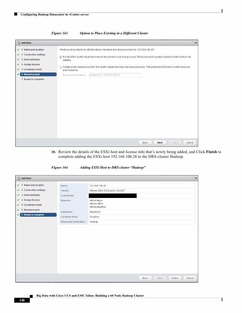
Configuring Hadoop Datacenter in vCenter server
Figure 163 Option to Place Existing in a Different Cluster
10. Review the details of the ESXi host and license info that’s newly being added, and Click Finish to complete adding the ESXi host 192.168.100.28 to the DRS-cluster Hadoop.
Figure 164 Adding ESXi Host to DRS-cluster “Hadoop”
148Big Data with Cisco UCS and EMC Isilon: Building a 60 Node Hadoop Cluster
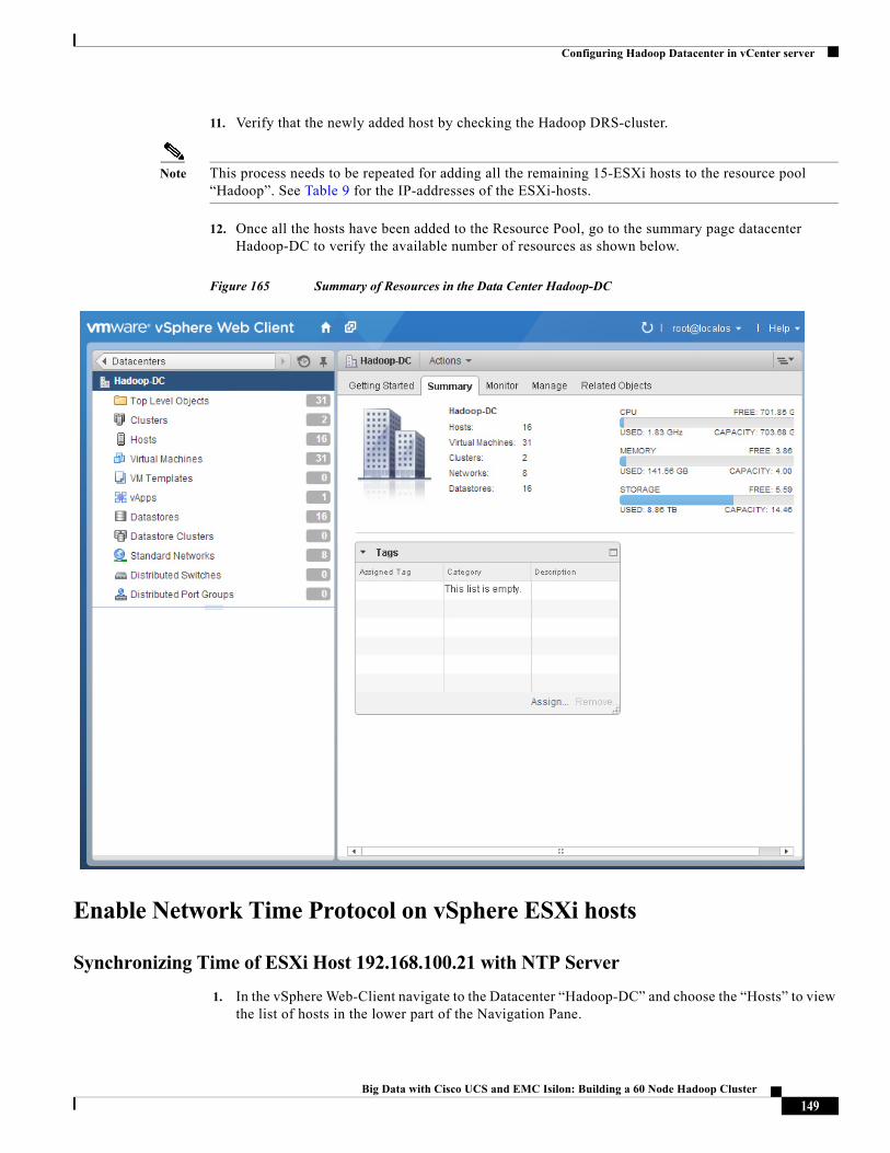
Configuring Hadoop Datacenter in vCenter server
11. Verify that the newly added host by checking the Hadoop DRS-cluster.
Note This process needs to be repeated for adding all the remaining 15-ESXi hosts to the resource pool “Hadoop”. See Table 9 for the IP-addresses of the ESXi-hosts.
12. Once all the hosts have been added to the Resource Pool, go to the summary page datacenter Hadoop-DC to verify the available number of resources as shown below.
Figure 165 Summary of Resources in the Data Center Hadoop-DC
Enable Network Time Protocol on vSphere ESXi hosts
Synchronizing Time of ESXi Host 192.168.100.21 with NTP Server
1. In the vSphere Web-Client navigate to the Datacenter “Hadoop-DC” and choose the “Hosts” to view the list of hosts in the lower part of the Navigation Pane.
149Big Data with Cisco UCS and EMC Isilon: Building a 60 Node Hadoop Cluster
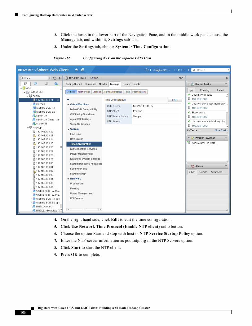
Configuring Hadoop Datacenter in vCenter server
2. Click the hosts in the lower part of the Navigation Pane, and in the middle work pane choose the Manage tab, and within it, Settings sub-tab.
3. Under the Settings tab, choose System > Time Configuration.
Figure 166 Configuring NTP on the vSphere ESXi Host
4. On the right hand side, click Edit to edit the time configuration.
5. Click Use Network Time Protocol (Enable NTP client) radio button.
6. Choose the option Start and stop with host in NTP Service Startup Policy option.
7. Enter the NTP-server information as pool.ntp.org in the NTP Servers option.
8. Click Start to start the NTP client.
9. Press OK to complete.
150Big Data with Cisco UCS and EMC Isilon: Building a 60 Node Hadoop Cluster
Configuring Hadoop Datacenter in vCenter server
Figure 167 Starting NTP-Client of the ESXi Host in Admin DRS-cluster
Synchronizing Time of ESXi-hosts (192.168.100.22 – 36) to Admin-VM
The 15 ESXi hosts of the Hadoop DRS-cluster shall be configured to synchronize their time with the local NTP-server that’s configured in the Admin-VM (192.168.100.51).
Using vCenter Web Client, perform the following steps on all the 15 ESXi hosts of the Hadoop DRS-cluster.
1. Navigate to the Datacenter “Hadoop-DC” and choose the “Hosts” to view the list of hosts in the lower part of the Navigation Pane.
2. C lick the hosts in the lower part of the Navigation Pane, and in the middle Work pane choose the Manage tab, and within it, Settings sub-tab.
3. Under the Settings tab, choose System > Time Configuration.
4. On the right hand side, click Edit to edit the time configuration.
5. Click the Use Network Time Protocol (Enable NTP client) radio-button.
6. Choose the option Start and stop with host in NTP Service Startup Policy option.
7. Add the NTP-server information as pool.ntp.org in the NTP Servers option.
8. Click Start button to start the NTP client.
9. Press OK to complete.
151Big Data with Cisco UCS and EMC Isilon: Building a 60 Node Hadoop Cluster
vSphere Big Data Extension 2.1 configurations
Figure 168 Configuring the NTP-client ESXi Hosts of the Hadoop DRS-cluster to Sync with Admin-VM
vSphere Big Data Extension 2.1 configurations
Pre-Requisites
The vSphere Web Client is necessary for installing and configuring the Big Data Extension (BDE) vApp on the vCenter Server. In this section, we will discuss the details on how to install BDE2.0 using vSphere Web Client.
Installing VMware vSphere Big Data Extensions 2.1 using VMware vSphere Web Client
1. Download the latest Big Data Extension 2.1 OVA file from www.vmware.com/downloads. It does not require any licenses.
2. Log onto the vCenter Server using VMware vSphere WebClient.
152Big Data with Cisco UCS and EMC Isilon: Building a 60 Node Hadoop Cluster
vSphere Big Data Extension 2.1 configurations
3. Navigate to the Hadoop-DC datacenter, choose Admin DRS resource pool, and right-click to get the context-menu.
4. In the context-menu, choose All vCenter Actions Deploy OVF Template option.
Figure 169 Deploy vSphere BDE 2.0 vApp OVF-Template in the Admin DRS-Cluster
5. In the Deploy OVF Template dialog box. click the Local file radio button and click Browse to browse and choose the “VMware-BigDataExtension-2.1.0…ova” file, and Click Next.
153Big Data with Cisco UCS and EMC Isilon: Building a 60 Node Hadoop Cluster
vSphere Big Data Extension 2.1 configurations
Figure 170 Deploying BDE vApp: Choose the vSphere BDE 2.1’s OVF File
6. Review the details of the vSphere BDE 2.1 vApp, and Click Next.
Figure 171 Deploying BDE vApp: Review the Details of the vApp
7. Review and Click Accept to accept the End-User License Agreement. Click Next.
154Big Data with Cisco UCS and EMC Isilon: Building a 60 Node Hadoop Cluster
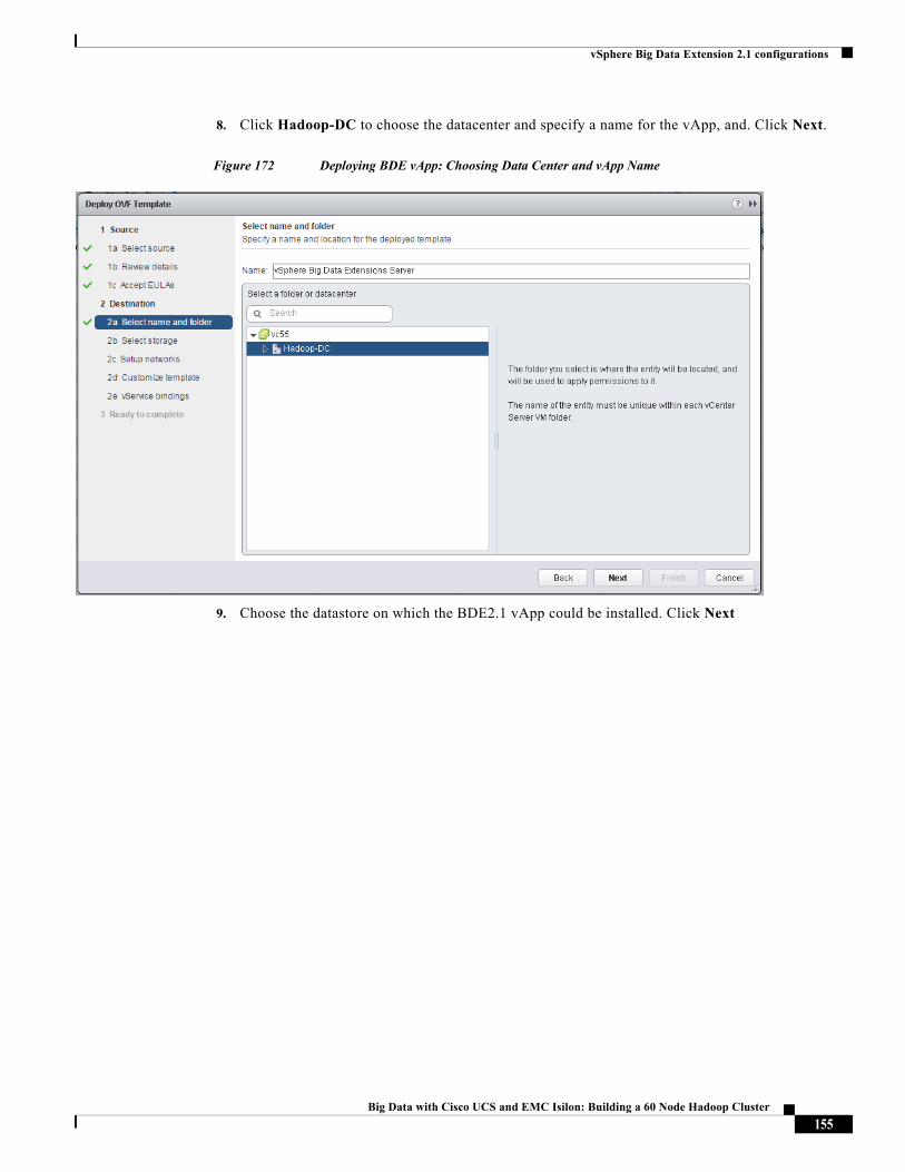
vSphere Big Data Extension 2.1 configurations
8. Click Hadoop-DC to choose the datacenter and specify a name for the vApp, and. Click Next.
Figure 172 Deploying BDE vApp: Choosing Data Center and vApp Name
9. Choose the datastore on which the BDE2.1 vApp could be installed. Click Next
155Big Data with Cisco UCS and EMC Isilon: Building a 60 Node Hadoop Cluster
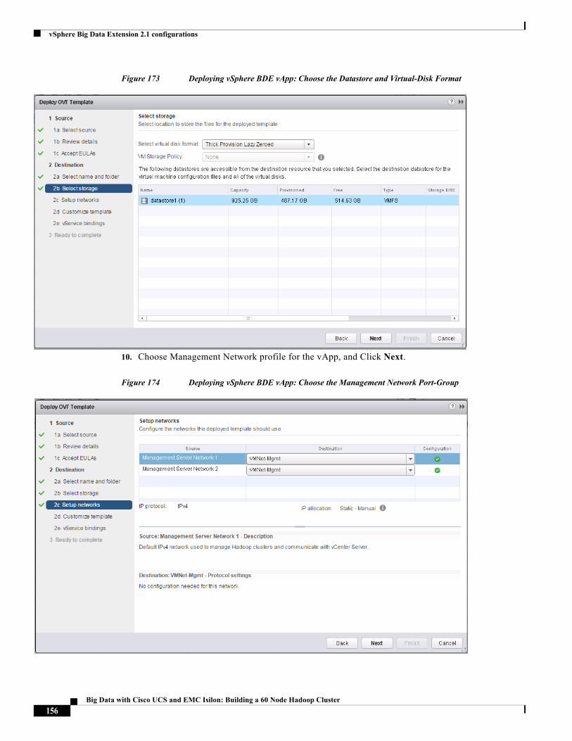
vSphere Big Data Extension 2.1 configurations
Figure 173 Deploying vSphere BDE vApp: Choose the Datastore and Virtual-Disk Format
10. Choose Management Network profile for the vApp, and Click Next.
Figure 174 Deploying vSphere BDE vApp: Choose the Management Network Port-Group
156Big Data with Cisco UCS and EMC Isilon: Building a 60 Node Hadoop Cluster
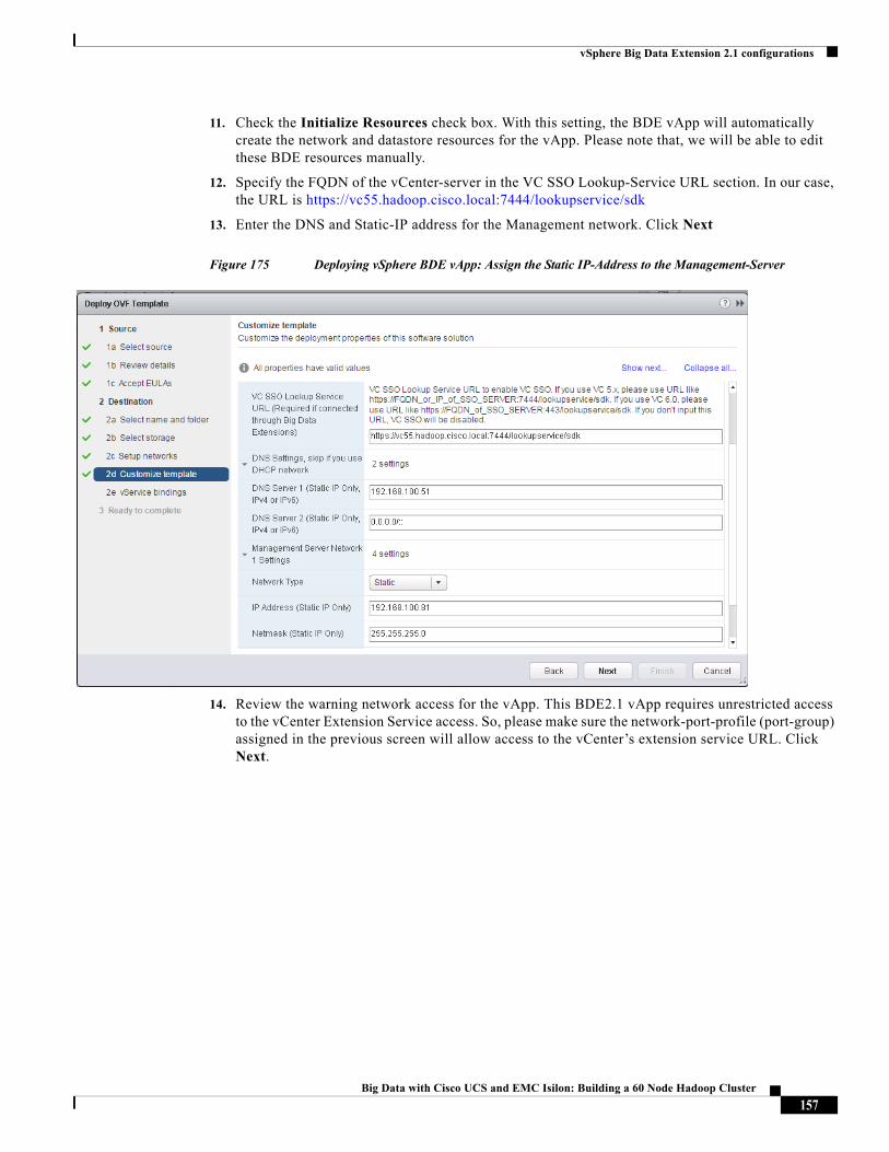
vSphere Big Data Extension 2.1 configurations
11. Check the Initialize Resources check box. With this setting, the BDE vApp will automatically create the network and datastore resources for the vApp. Please note that, we will be able to edit these BDE resources manually.
12. Specify the FQDN of the vCenter-server in the VC SSO Lookup-Service URL section. In our case, the URL is https://vc55.hadoop.cisco.local:7444/lookupservice/sdk
13. Enter the DNS and Static-IP address for the Management network. Click Next
Figure 175 Deploying vSphere BDE vApp: Assign the Static IP-Address to the Management-Server
14. Review the warning network access for the vApp. This BDE2.1 vApp requires unrestricted access to the vCenter Extension Service access. So, please make sure the network-port-profile (port-group) assigned in the previous screen will allow access to the vCenter’s extension service URL. Click Next.
157Big Data with Cisco UCS and EMC Isilon: Building a 60 Node Hadoop Cluster
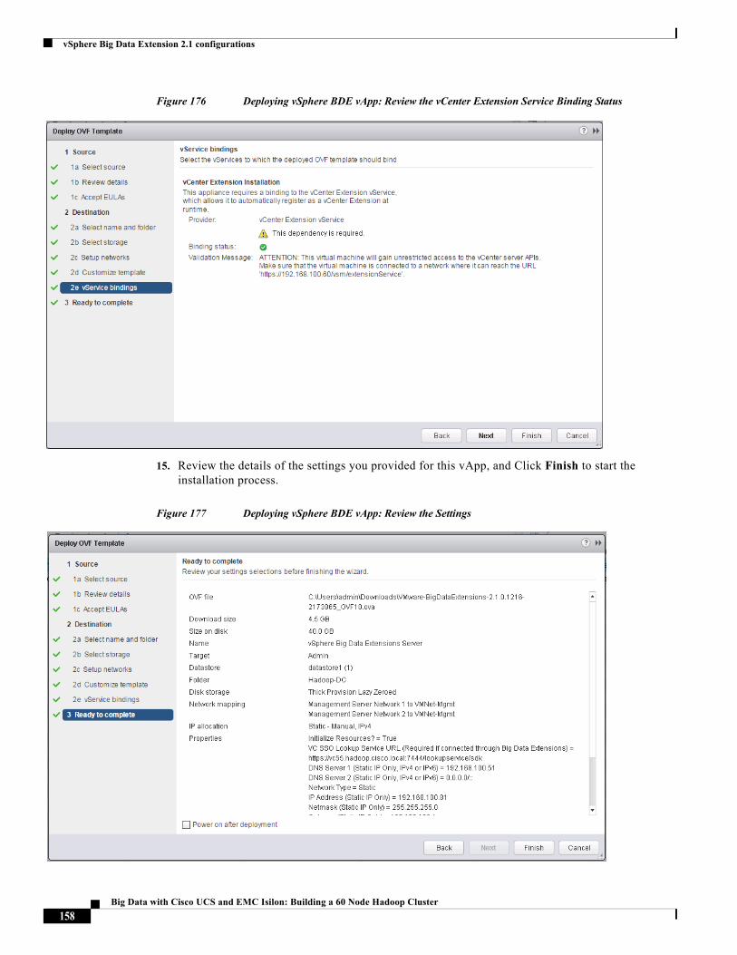
vSphere Big Data Extension 2.1 configurations
Figure 176 Deploying vSphere BDE vApp: Review the vCenter Extension Service Binding Status
15. Review the details of the settings you provided for this vApp, and Click Finish to start the installation process.
Figure 177 Deploying vSphere BDE vApp: Review the Settings
158Big Data with Cisco UCS and EMC Isilon: Building a 60 Node Hadoop Cluster
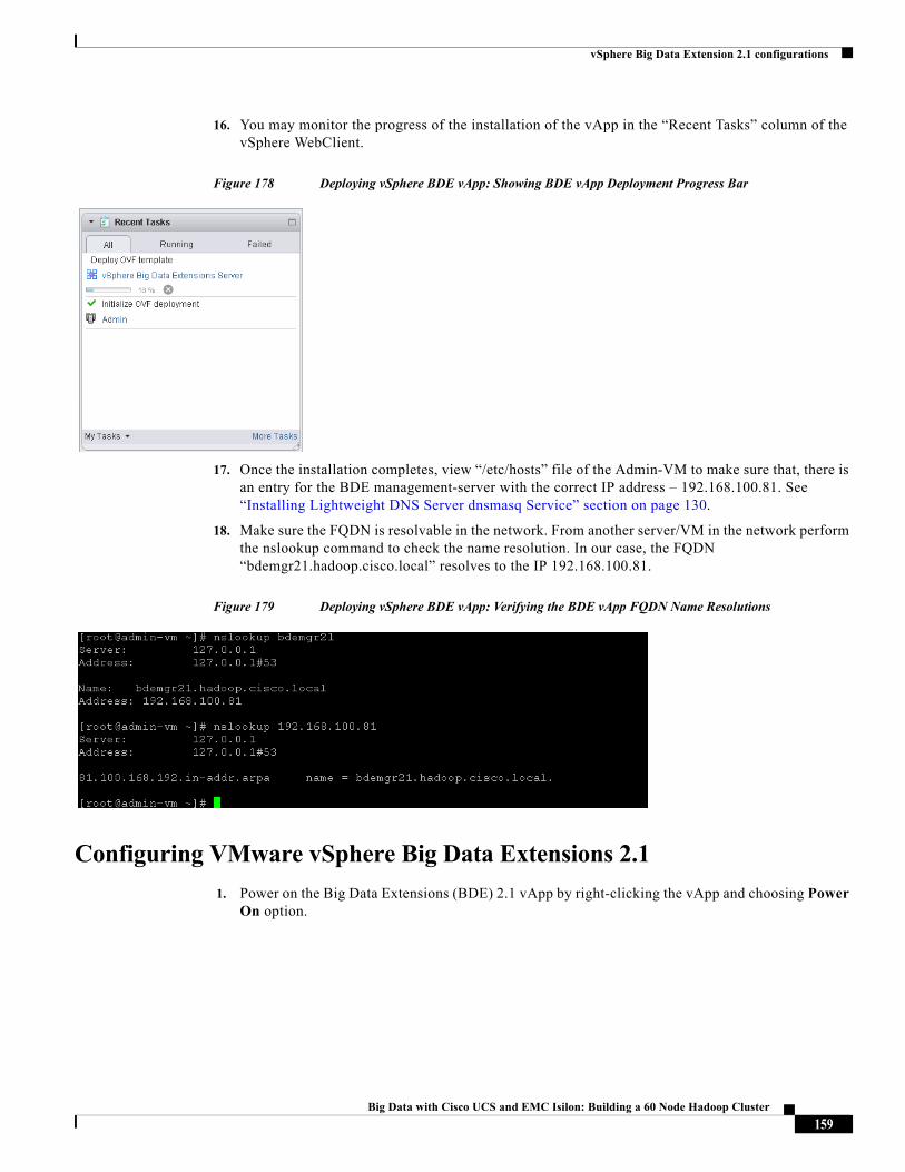
vSphere Big Data Extension 2.1 configurations
16. You may monitor the progress of the installation of the vApp in the “Recent Tasks” column of the vSphere WebClient.
Figure 178 Deploying vSphere BDE vApp: Showing BDE vApp Deployment Progress Bar
17. Once the installation completes, view “/etc/hosts” file of the Admin-VM to make sure that, there is an entry for the BDE management-server with the correct IP address – 192.168.100.81. See “Installing Lightweight DNS Server dnsmasq Service” section on page 130.
18. Make sure the FQDN is resolvable in the network. From another server/VM in the network perform the nslookup command to check the name resolution. In our case, the FQDN “bdemgr21.hadoop.cisco.local” resolves to the IP 192.168.100.81.
Figure 179 Deploying vSphere BDE vApp: Verifying the BDE vApp FQDN Name Resolutions
Configuring VMware vSphere Big Data Extensions 2.1
1. Power on the Big Data Extensions (BDE) 2.1 vApp by right-clicking the vApp and choosing Power On option.
159Big Data with Cisco UCS and EMC Isilon: Building a 60 Node Hadoop Cluster
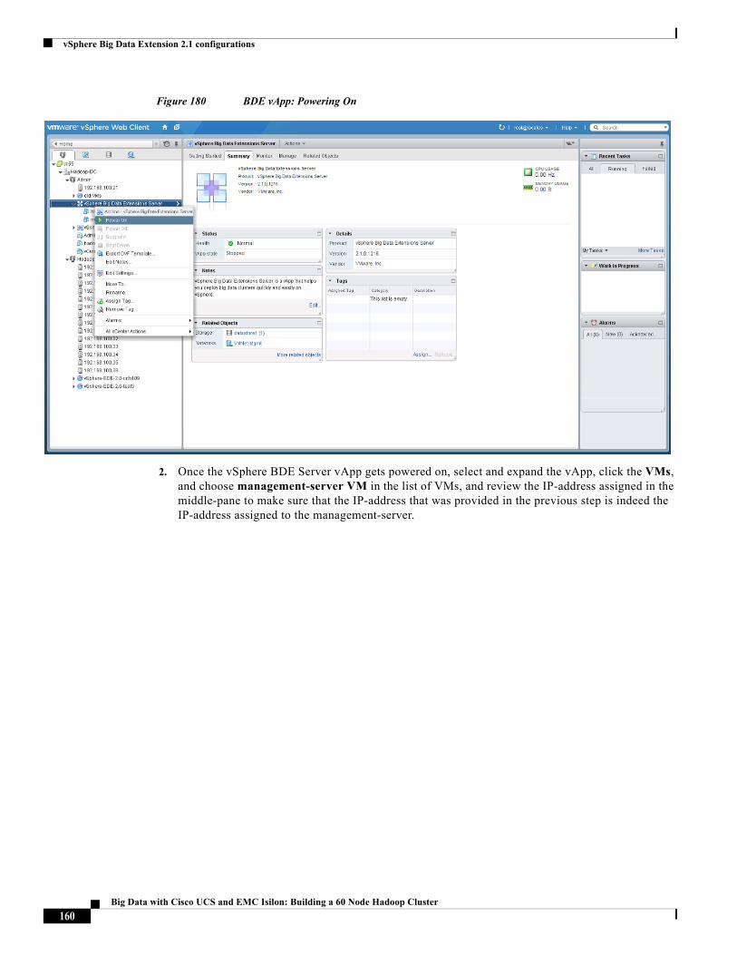
vSphere Big Data Extension 2.1 configurations
Figure 180 BDE vApp: Powering On
2. Once the vSphere BDE Server vApp gets powered on, select and expand the vApp, click the VMs, and choose management-server VM in the list of VMs, and review the IP-address assigned in the middle-pane to make sure that the IP-address that was provided in the previous step is indeed the IP-address assigned to the management-server.
160Big Data with Cisco UCS and EMC Isilon: Building a 60 Node Hadoop Cluster
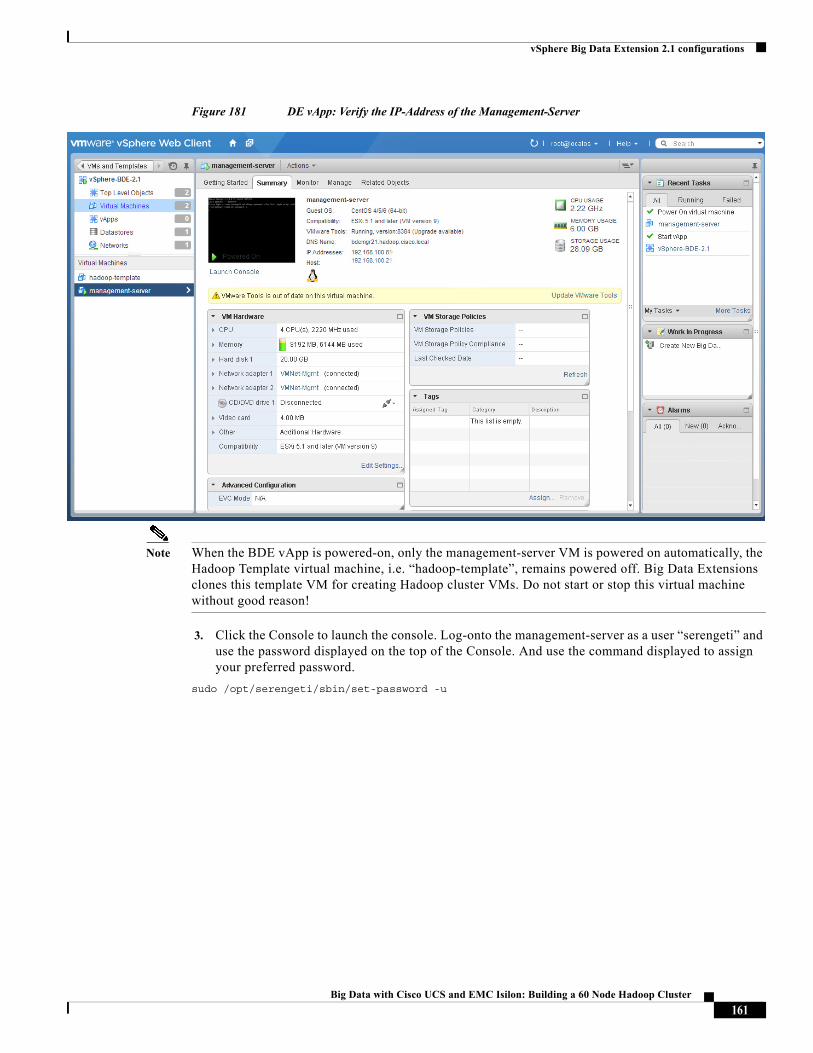
vSphere Big Data Extension 2.1 configurations
Figure 181 DE vApp: Verify the IP-Address of the Management-Server
Note When the BDE vApp is powered-on, only the management-server VM is powered on automatically, the Hadoop Template virtual machine, i.e. “hadoop-template”, remains powered off. Big Data Extensions clones this template VM for creating Hadoop cluster VMs. Do not start or stop this virtual machine without good reason!
3. Click the Console to launch the console. Log-onto the management-server as a user “serengeti” and use the password displayed on the top of the Console. And use the command displayed to assign your preferred password.
sudo /opt/serengeti/sbin/set-password -u
161Big Data with Cisco UCS and EMC Isilon: Building a 60 Node Hadoop Cluster
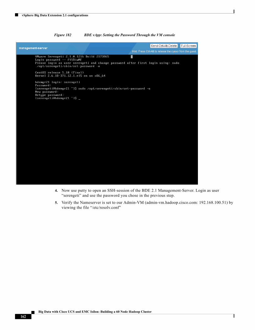
vSphere Big Data Extension 2.1 configurations
Figure 182 BDE vApp: Setting the Password Through the VM console
4. Now use putty to open an SSH-session of the BDE 2.1 Management-Server. Login as user “serengeti” and use the password you chose in the previous step.
5. Verify the Nameserver is set to our Admin-VM (admin-vm.hadoop.cisco.com: 192.168.100.51) by viewing the file “/etc/resolv.conf”
162Big Data with Cisco UCS and EMC Isilon: Building a 60 Node Hadoop Cluster
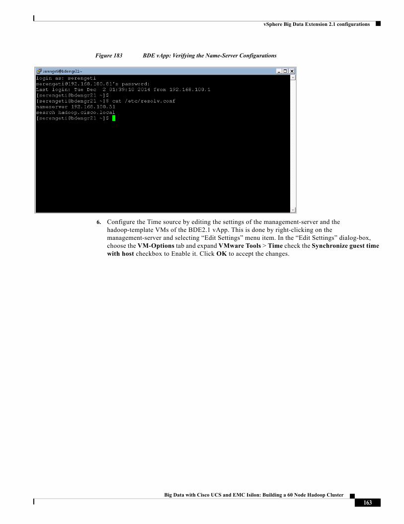
vSphere Big Data Extension 2.1 configurations
Figure 183 BDE vApp: Verifying the Name-Server Configurations
6. Configure the Time source by editing the settings of the management-server and the hadoop-template VMs of the BDE2.1 vApp. This is done by right-clicking on the management-server and selecting “Edit Settings” menu item. In the “Edit Settings” dialog-box, choose the VM-Options tab and expand VMware Tools > Time check the Synchronize guest time with host checkbox to Enable it. Click OK to accept the changes.
163Big Data with Cisco UCS and EMC Isilon: Building a 60 Node Hadoop Cluster
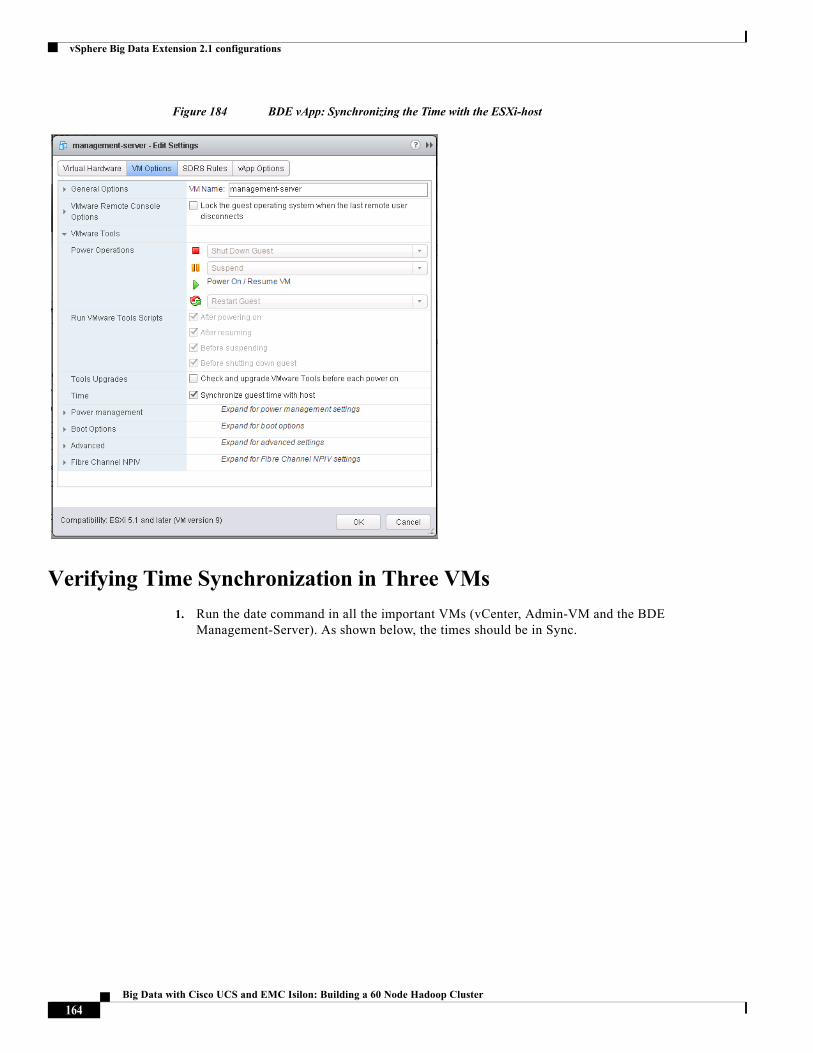
vSphere Big Data Extension 2.1 configurations
Figure 184 BDE vApp: Synchronizing the Time with the ESXi-host
Verifying Time Synchronization in Three VMs
1. Run the date command in all the important VMs (vCenter, Admin-VM and the BDE Management-Server). As shown below, the times should be in Sync.
164Big Data with Cisco UCS and EMC Isilon: Building a 60 Node Hadoop Cluster
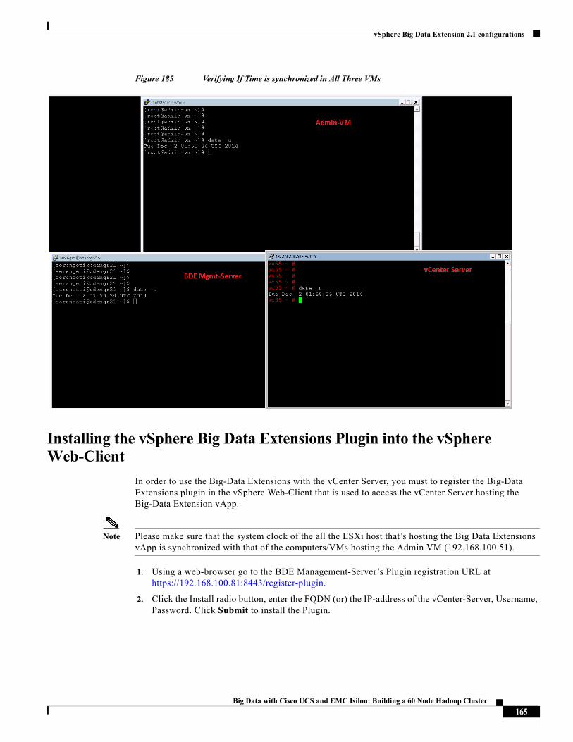
vSphere Big Data Extension 2.1 configurations
Figure 185 Verifying If Time is synchronized in All Three VMs
Installing the vSphere Big Data Extensions Plugin into the vSphere Web-Client
In order to use the Big-Data Extensions with the vCenter Server, you must to register the Big-Data Extensions plugin in the vSphere Web-Client that is used to access the vCenter Server hosting the Big-Data Extension vApp.
Note Please make sure that the system clock of the all the ESXi host that’s hosting the Big Data Extensions vApp is synchronized with that of the computers/VMs hosting the Admin VM (192.168.100.51).
1. Using a web-browser go to the BDE Management-Server’s Plugin registration URL at https://192.168.100.81:8443/register-plugin.
2. Click the Install radio button, enter the FQDN (or) the IP-address of the vCenter-Server, Username, Password. Click Submit to install the Plugin.
165Big Data with Cisco UCS and EMC Isilon: Building a 60 Node Hadoop Cluster
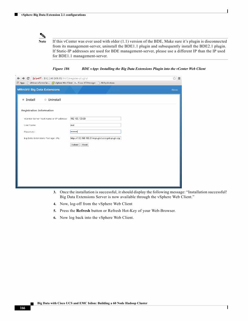
vSphere Big Data Extension 2.1 configurations
Note If this vCenter was ever used with older (1.1) version of the BDE, Make sure it’s plugin is disconnected from its management-server, uninstall the BDE1.1 plugin and subsequently install the BDE2.1 plugin. If Static-IP addresses are used for BDE management-server, please use a different IP than the IP used for BDE1.1 management-server.
Figure 186 BDE vApp: Installing the Big Data Extensions Plugin into the vCenter Web Client
3. Once the installation is successful, it should display the following message: “Installation successful! Big Data Extensions Server is now available through the vSphere Web Client.”
4. Now, log-off from the vSphere Web Client
5. Press the Refresh button or Refresh Hot-Key of your Web-Browser.
6. Now log back into the vSphere Web Client.
166Big Data with Cisco UCS and EMC Isilon: Building a 60 Node Hadoop Cluster
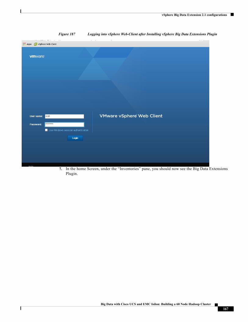
vSphere Big Data Extension 2.1 configurations
Figure 187 Logging into vSphere Web-Client after Installing vSphere Big Data Extensions Plugin
7. In the home Screen, under the “Inventories” pane, you should now see the Big Data Extensions Plugin.
167Big Data with Cisco UCS and EMC Isilon: Building a 60 Node Hadoop Cluster
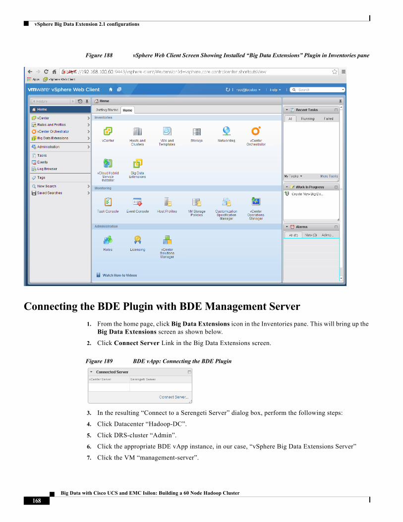
vSphere Big Data Extension 2.1 configurations
Figure 188 vSphere Web Client Screen Showing Installed “Big Data Extensions” Plugin in Inventories pane
Connecting the BDE Plugin with BDE Management Server
1. From the home page, click Big Data Extensions icon in the Inventories pane. This will bring up the Big Data Extensions screen as shown below.
2. Click Connect Server Link in the Big Data Extensions screen.
Figure 189 BDE vApp: Connecting the BDE Plugin
3. In the resulting “Connect to a Serengeti Server” dialog box, perform the following steps:
4. Click Datacenter “Hadoop-DC”.
5. Click DRS-cluster “Admin”.
6. Click the appropriate BDE vApp instance, in our case, “vSphere Big Data Extensions Server”
7. Click the VM “management-server”.
168Big Data with Cisco UCS and EMC Isilon: Building a 60 Node Hadoop Cluster
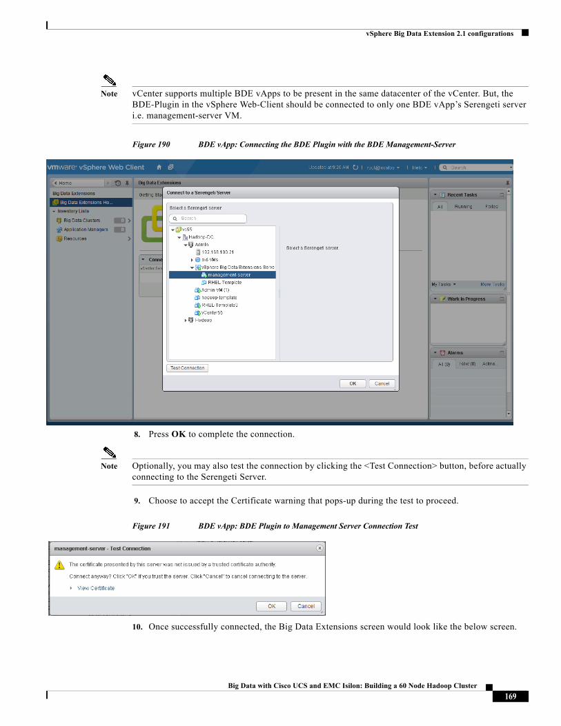
vSphere Big Data Extension 2.1 configurations
Note vCenter supports multiple BDE vApps to be present in the same datacenter of the vCenter. But, the BDE-Plugin in the vSphere Web-Client should be connected to only one BDE vApp’s Serengeti server i.e. management-server VM.
Figure 190 BDE vApp: Connecting the BDE Plugin with the BDE Management-Server
8. Press OK to complete the connection.
Note Optionally, you may also test the connection by clicking the <Test Connection> button, before actually connecting to the Serengeti Server.
9. Choose to accept the Certificate warning that pops-up during the test to proceed.
Figure 191 BDE vApp: BDE Plugin to Management Server Connection Test
10. Once successfully connected, the Big Data Extensions screen would look like the below screen.
169Big Data with Cisco UCS and EMC Isilon: Building a 60 Node Hadoop Cluster

vSphere Big Data Extension 2.1 configurations
Figure 192 BDE vApp: Big Data Extensions Plugin is Connected with the Serengeti (BDE) Management-Server
Configuring Datastores and Network Resources in Big Data Extensions
1. In the BDE home screen (Figure 193), click the Resources.
2. Click the “Datastores” under “Inventory Lists”.
3. In the Middle-pane, click + to create a datastore resource-pool.
4. Give a name hadoopLocalDS.
5. Change the Type field drop-down box, choose Local.
6. Choose all the datastores that belong to the Hadoop DRS-cluster. In other words, choose all but the datastore that belongs to the Admin DRS-cluster. In our case, datastore1 (1) belonged to the only ESXi host that is part of the Admin DRS-cluster, so we left that one datastore unchecked.
7. Press OK to continue.
170Big Data with Cisco UCS and EMC Isilon: Building a 60 Node Hadoop Cluster
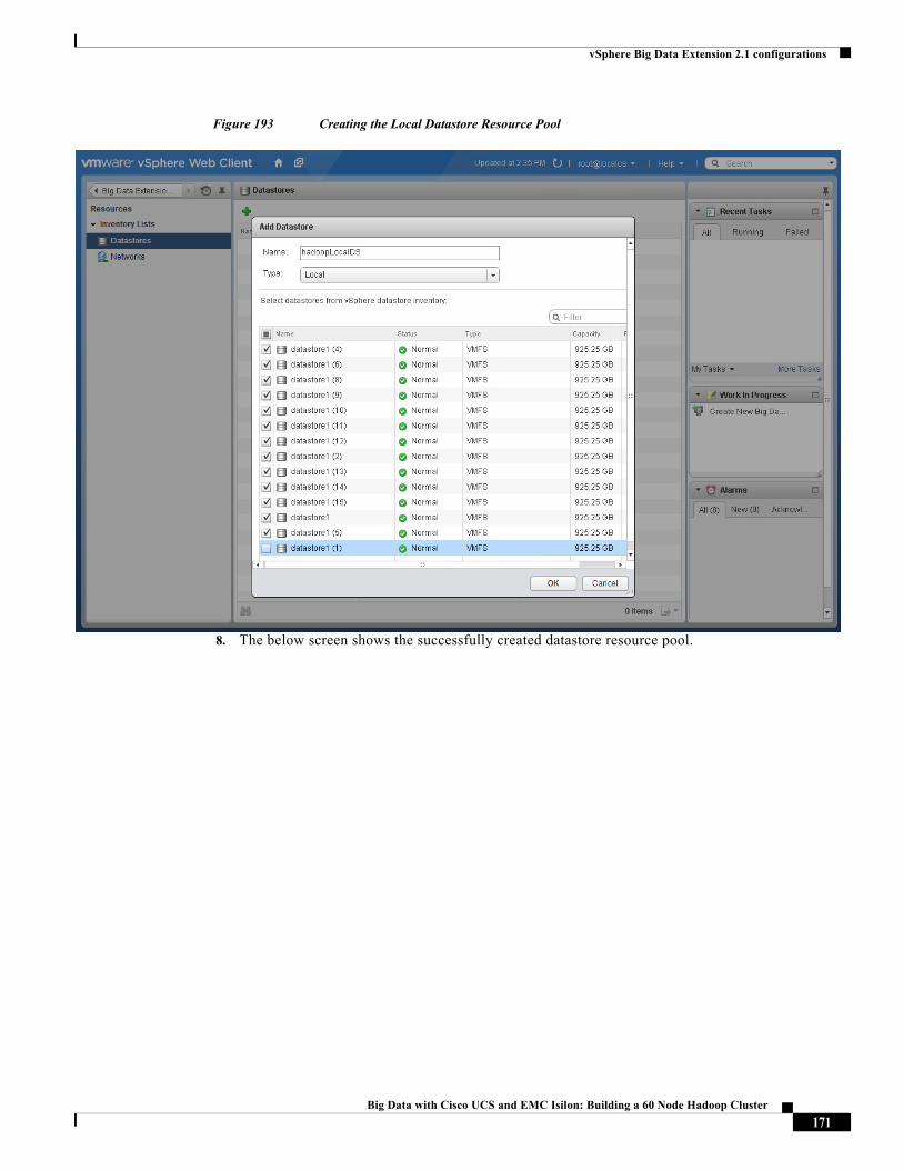
vSphere Big Data Extension 2.1 configurations
Figure 193 Creating the Local Datastore Resource Pool
8. The below screen shows the successfully created datastore resource pool.
171Big Data with Cisco UCS and EMC Isilon: Building a 60 Node Hadoop Cluster
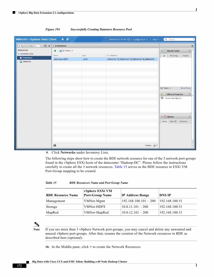
vSphere Big Data Extension 2.1 configurations
Figure 194 Successfully Creating Datastore Resource Pool
9. Click Networks under Inventory Lists.
The following steps show how to create the BDE network resource for one of the 3 network port-groups found in the vSphere ESXi hosts of the datacenter “Hadoop-DC”. Please follow the instructions carefully to create all the 3 network resources. Table 15 serves as the BDE resource to ESXi VM Port-Group mapping to be created.
Note If you see more than 3 vSphere Network port-groups, you may cancel and delete any unwanted and unused vSphere port-groups. After that, resume the creation of the Network resources in BDE as described here (optional).
10. In the Middle-pane, click + to create the Network Resources.
Table 15 BDE Resources Name and Port Group Name
BDE Resource NamevSphere ESXi VM Port-Group Name IP Address Range DNS IP
Management VMNet-Mgmt 192.168.100.101 – 200 192.168.100.51
Storage VMNet-HDFS 10.0.11.101 – 200 192.168.100.51
MapRed VMNet-MapRed 10.0.12.101 – 200 192.168.100.51
172Big Data with Cisco UCS and EMC Isilon: Building a 60 Node Hadoop Cluster
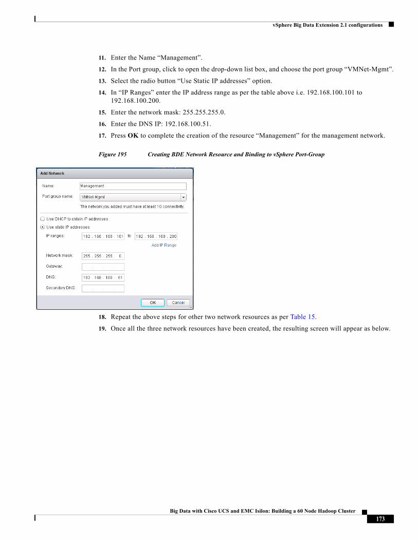
vSphere Big Data Extension 2.1 configurations
11. Enter the Name “Management”.
12. In the Port group, click to open the drop-down list box, and choose the port group “VMNet-Mgmt”.
13. Select the radio button “Use Static IP addresses” option.
14. In “IP Ranges” enter the IP address range as per the table above i.e. 192.168.100.101 to 192.168.100.200.
15. Enter the network mask: 255.255.255.0.
16. Enter the DNS IP: 192.168.100.51.
17. Press OK to complete the creation of the resource “Management” for the management network.
Figure 195 Creating BDE Network Resource and Binding to vSphere Port-Group
18. Repeat the above steps for other two network resources as per Table 15.
19. Once all the three network resources have been created, the resulting screen will appear as below.
173Big Data with Cisco UCS and EMC Isilon: Building a 60 Node Hadoop Cluster
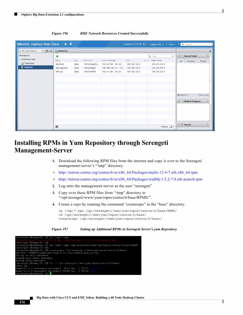
vSphere Big Data Extension 2.1 configurations
Figure 196 BDE Network Resources Created Successfully
Installing RPMs in Yum Repository through Serengeti Management-Server
1. Download the following RPM files from the internet and copy it over to the Serengeti management-server’s “/tmp” directory.
• http://mirror.centos.org/centos/6/os/x86_64/Packages/mailx-12.4-7.el6.x86_64.rpm
• http://mirror.centos.org/centos/6/os/x86_64/Packages/wsdl4j-1.5.2-7.8.el6.noarch.rpm
2. Log onto the management-server as the user “serengeti”
3. Copy over these RPM files from “/tmp” directory to “/opt/serengeti/www/yum/repos/centos/6/base/RPMS/”.
4. Create a repo by running the command “createrepo” in the “base” directory.
cp /tmp/*.rpm /opt/serengeti/www/yum/repos/centos/6/base/RPMS/cd /opt/serengeti/www/yum/repos/centos/6/base/createrepo /opt/serengeti/www/yum/repos/centos/6/base/
Figure 197 Setting up Additional RPMs in Serengeti Server’s yum Repository
174Big Data with Cisco UCS and EMC Isilon: Building a 60 Node Hadoop Cluster
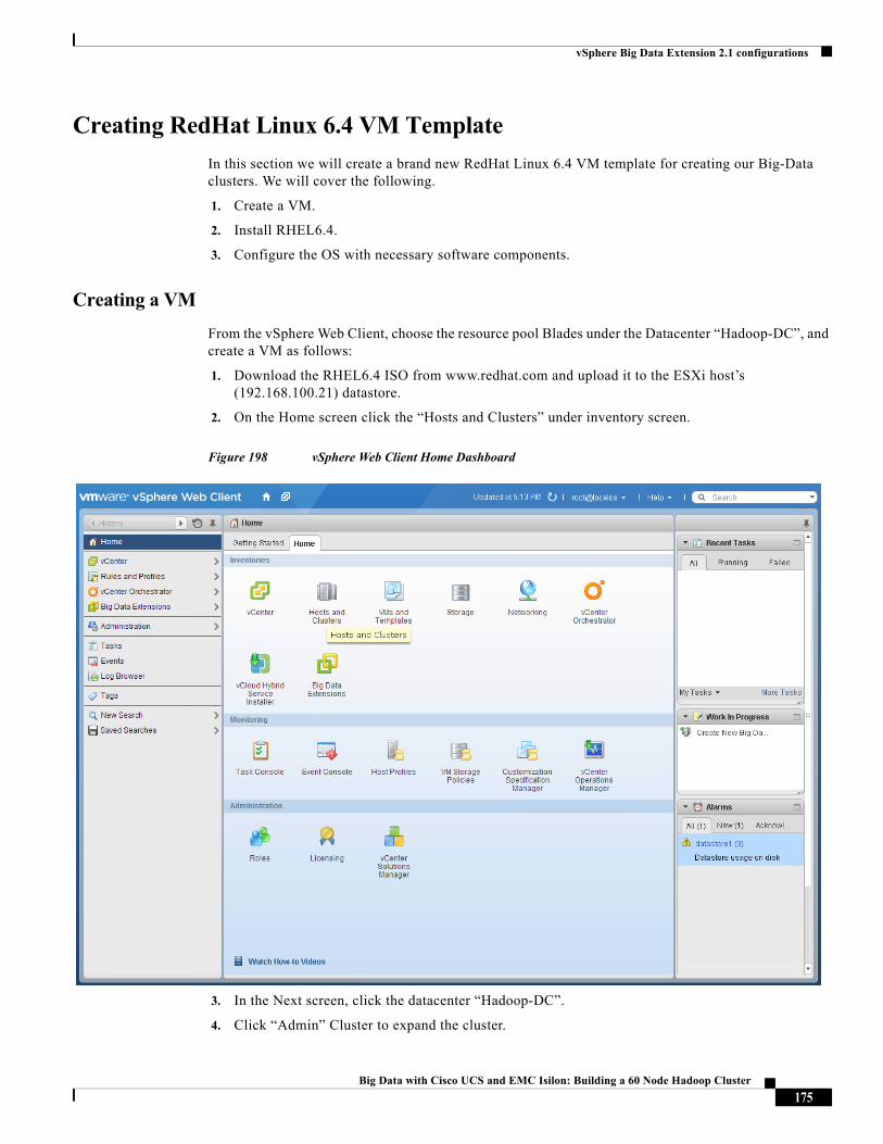
vSphere Big Data Extension 2.1 configurations
Creating RedHat Linux 6.4 VM Template
In this section we will create a brand new RedHat Linux 6.4 VM template for creating our Big-Data clusters. We will cover the following.
1. Create a VM.
2. Install RHEL6.4.
3. Configure the OS with necessary software components.
Creating a VM
From the vSphere Web Client, choose the resource pool Blades under the Datacenter “Hadoop-DC”, and create a VM as follows:
1. Download the RHEL6.4 ISO from www.redhat.com and upload it to the ESXi host’s (192.168.100.21) datastore.
2. On the Home screen click the “Hosts and Clusters” under inventory screen.
Figure 198 vSphere Web Client Home Dashboard
3. In the Next screen, click the datacenter “Hadoop-DC”.
4. Click “Admin” Cluster to expand the cluster.
175Big Data with Cisco UCS and EMC Isilon: Building a 60 Node Hadoop Cluster
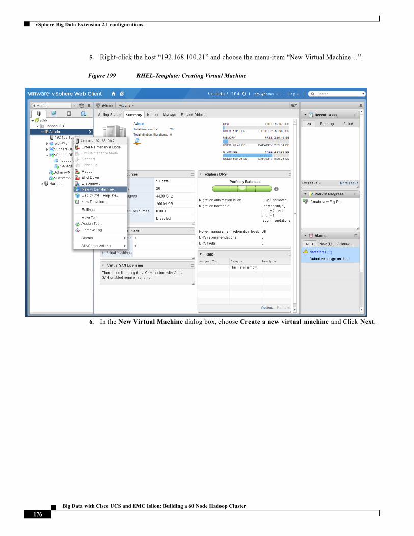
vSphere Big Data Extension 2.1 configurations
5. Right-click the host “192.168.100.21” and choose the menu-item “New Virtual Machine…”.
Figure 199 RHEL-Template: Creating Virtual Machine
6. In the New Virtual Machine dialog box, choose Create a new virtual machine and Click Next.
176Big Data with Cisco UCS and EMC Isilon: Building a 60 Node Hadoop Cluster
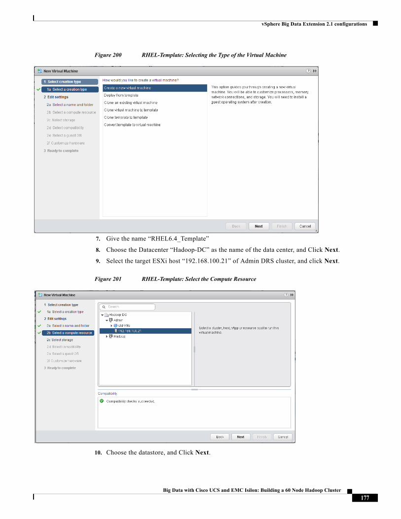
vSphere Big Data Extension 2.1 configurations
Figure 200 RHEL-Template: Selecting the Type of the Virtual Machine
7. Give the name “RHEL6.4_Template”
8. Choose the Datacenter “Hadoop-DC” as the name of the data center, and Click Next.
9. Select the target ESXi host “192.168.100.21” of Admin DRS cluster, and click Next.
Figure 201 RHEL-Template: Select the Compute Resource
10. Choose the datastore, and Click Next.
177Big Data with Cisco UCS and EMC Isilon: Building a 60 Node Hadoop Cluster
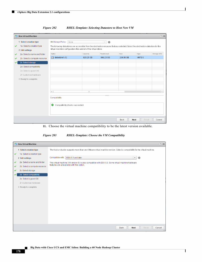
vSphere Big Data Extension 2.1 configurations
Figure 202 RHEL-Template: Selecting Datastore to Host New VM
11. Choose the virtual machine compatibility to be the latest version available.
Figure 203 RHEL-Template: Choose the VM Compatibility
178Big Data with Cisco UCS and EMC Isilon: Building a 60 Node Hadoop Cluster
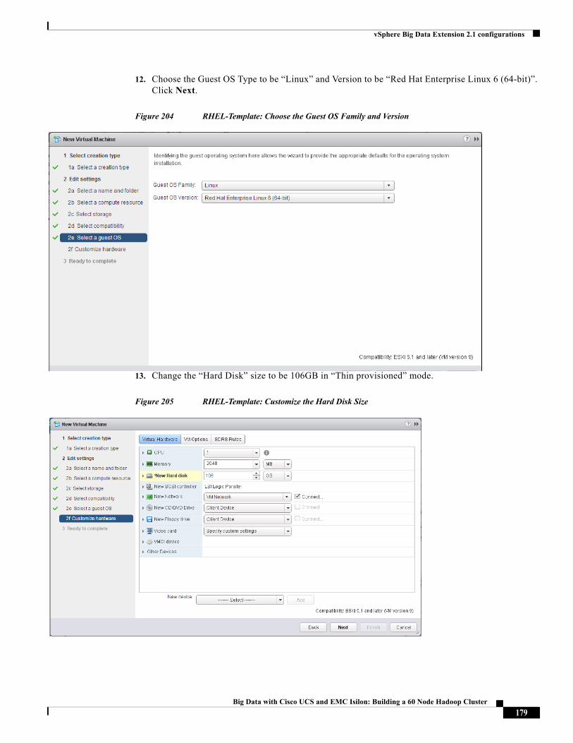
vSphere Big Data Extension 2.1 configurations
12. Choose the Guest OS Type to be “Linux” and Version to be “Red Hat Enterprise Linux 6 (64-bit)”. Click Next.
Figure 204 RHEL-Template: Choose the Guest OS Family and Version
13. Change the “Hard Disk” size to be 106GB in “Thin provisioned” mode.
Figure 205 RHEL-Template: Customize the Hard Disk Size
179Big Data with Cisco UCS and EMC Isilon: Building a 60 Node Hadoop Cluster
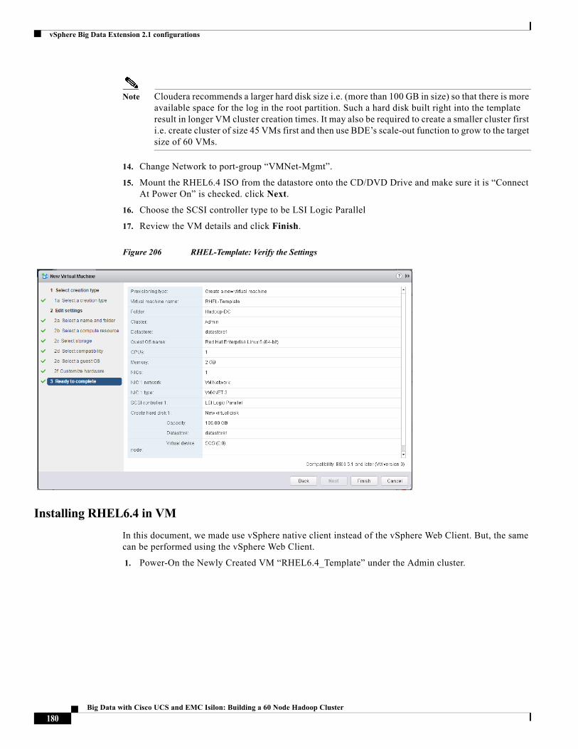
vSphere Big Data Extension 2.1 configurations
Note Cloudera recommends a larger hard disk size i.e. (more than 100 GB in size) so that there is more available space for the log in the root partition. Such a hard disk built right into the template result in longer VM cluster creation times. It may also be required to create a smaller cluster first i.e. create cluster of size 45 VMs first and then use BDE’s scale-out function to grow to the target size of 60 VMs.
14. Change Network to port-group “VMNet-Mgmt”.
15. Mount the RHEL6.4 ISO from the datastore onto the CD/DVD Drive and make sure it is “Connect At Power On” is checked. click Next.
16. Choose the SCSI controller type to be LSI Logic Parallel
17. Review the VM details and click Finish.
Figure 206 RHEL-Template: Verify the Settings
Installing RHEL6.4 in VM
In this document, we made use vSphere native client instead of the vSphere Web Client. But, the same can be performed using the vSphere Web Client.
1. Power-On the Newly Created VM “RHEL6.4_Template” under the Admin cluster.
180Big Data with Cisco UCS and EMC Isilon: Building a 60 Node Hadoop Cluster
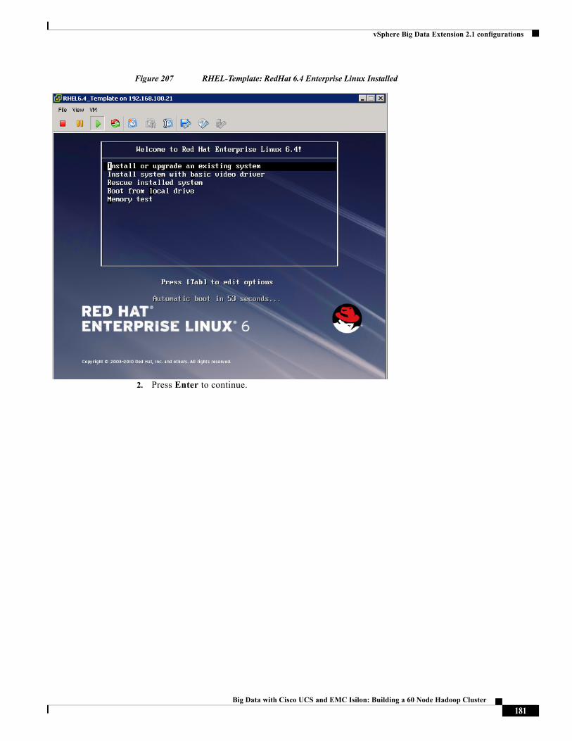
vSphere Big Data Extension 2.1 configurations
Figure 207 RHEL-Template: RedHat 6.4 Enterprise Linux Installed
2. Press Enter to continue.
181Big Data with Cisco UCS and EMC Isilon: Building a 60 Node Hadoop Cluster
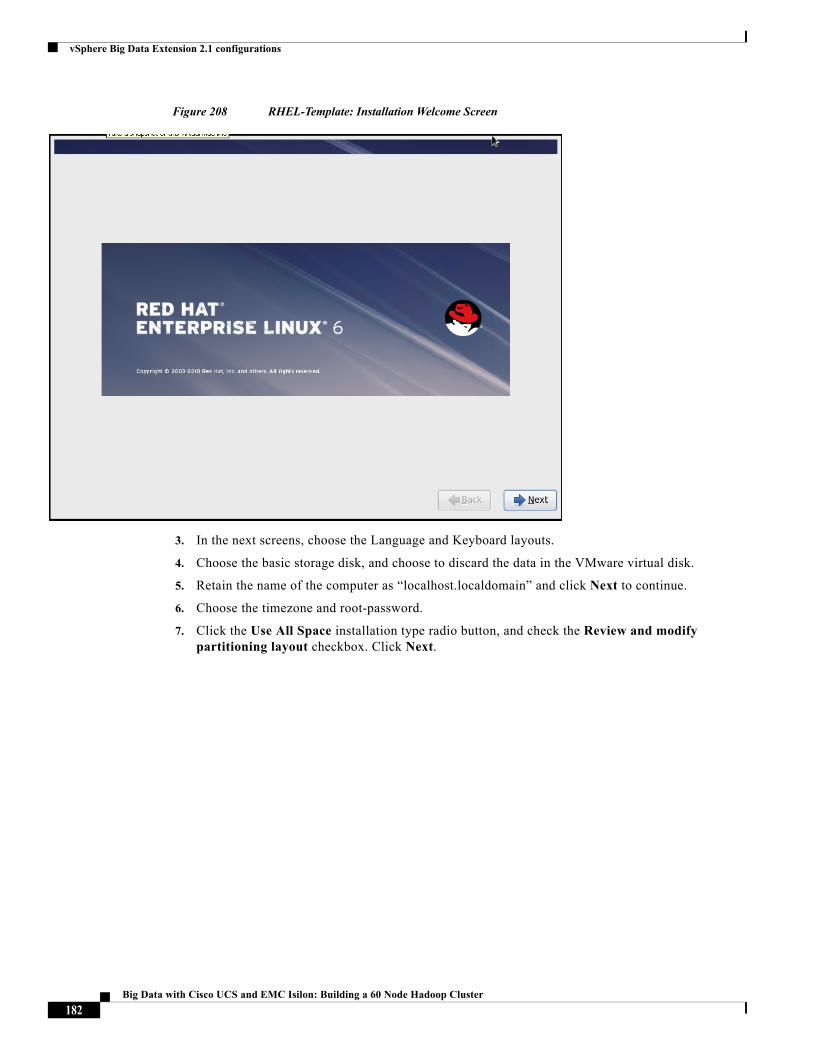
vSphere Big Data Extension 2.1 configurations
Figure 208 RHEL-Template: Installation Welcome Screen
3. In the next screens, choose the Language and Keyboard layouts.
4. Choose the basic storage disk, and choose to discard the data in the VMware virtual disk.
5. Retain the name of the computer as “localhost.localdomain” and click Next to continue.
6. Choose the timezone and root-password.
7. Click the Use All Space installation type radio button, and check the Review and modify partitioning layout checkbox. Click Next.
182Big Data with Cisco UCS and EMC Isilon: Building a 60 Node Hadoop Cluster
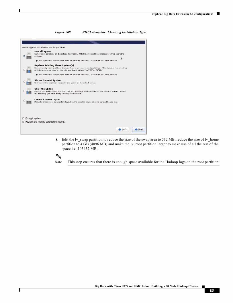
vSphere Big Data Extension 2.1 configurations
Figure 209 RHEL-Template: Choosing Installation Type
8. Edit the lv_swap partition to reduce the size of the swap area to 512 MB, reduce the size of lv_home partition to 4 GB (4096 MB) and make the lv_root partition larger to make use of all the rest of the space i.e. 103432 MB.
Note This step ensures that there is enough space available for the Hadoop logs on the root partition.
183Big Data with Cisco UCS and EMC Isilon: Building a 60 Node Hadoop Cluster
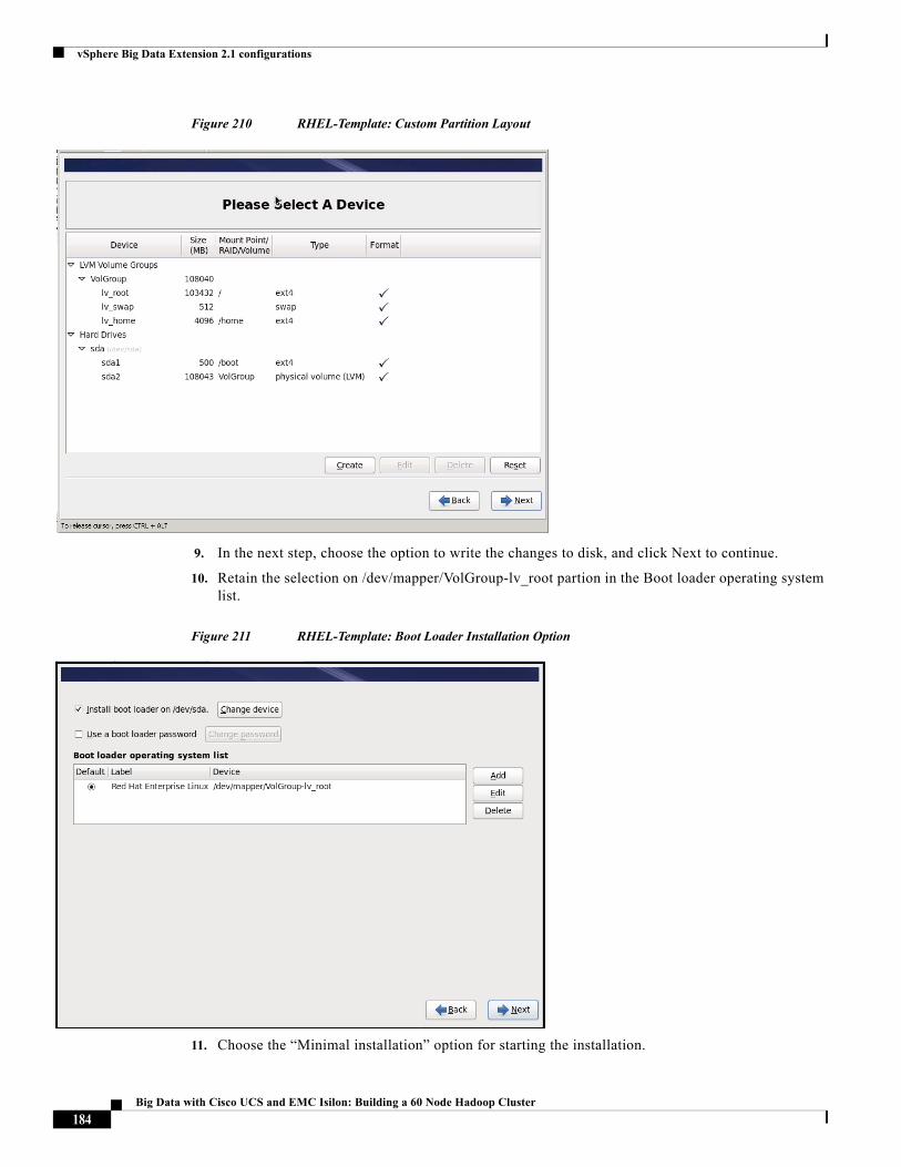
vSphere Big Data Extension 2.1 configurations
Figure 210 RHEL-Template: Custom Partition Layout
9. In the next step, choose the option to write the changes to disk, and click Next to continue.
10. Retain the selection on /dev/mapper/VolGroup-lv_root partion in the Boot loader operating system list.
Figure 211 RHEL-Template: Boot Loader Installation Option
11. Choose the “Minimal installation” option for starting the installation.
184Big Data with Cisco UCS and EMC Isilon: Building a 60 Node Hadoop Cluster
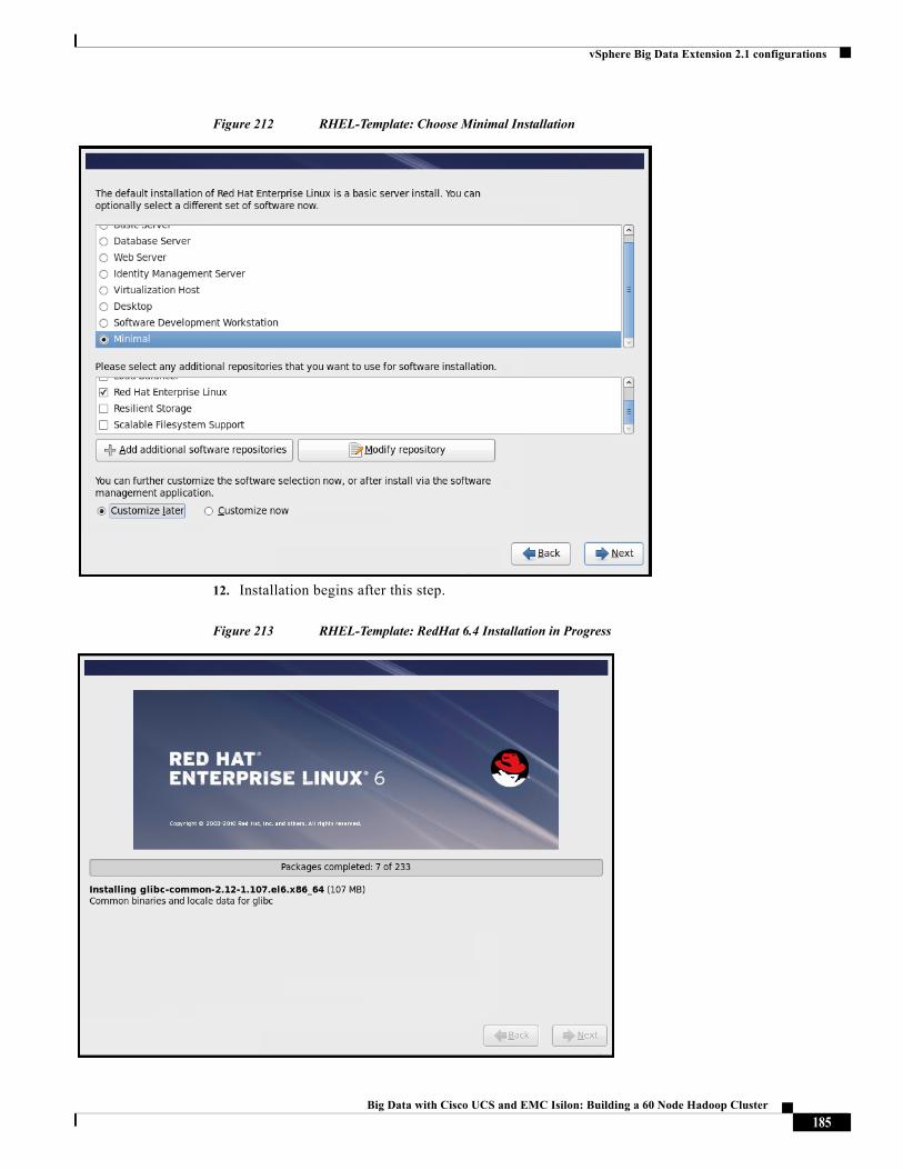
vSphere Big Data Extension 2.1 configurations
Figure 212 RHEL-Template: Choose Minimal Installation
12. Installation begins after this step.
Figure 213 RHEL-Template: RedHat 6.4 Installation in Progress
185Big Data with Cisco UCS and EMC Isilon: Building a 60 Node Hadoop Cluster
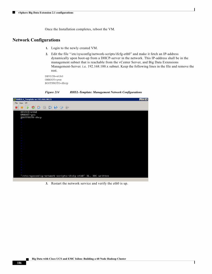
vSphere Big Data Extension 2.1 configurations
Once the Installation completes, reboot the VM.
Network Configurations
1. Login to the newly created VM.
2. Edit the file “/etc/sysconfig/network-scripts/ifcfg-eth0” and make it fetch an IP-address dynamically upon boot-up from a DHCP-server in the network. This IP-address shall be in the management subnet that is reachable from the vCenter Server, and Big Data Extensions Management-Server. i.e. 192.168.100.x subnet. Keep the following lines in the file and remove the rest.
DEVICE=eth0ONBOOT=yesBOOTPROTO=dhcp
Figure 214 RHEL-Template: Management Network Configurations
3. Restart the network service and verify the eth0 is up.
186Big Data with Cisco UCS and EMC Isilon: Building a 60 Node Hadoop Cluster
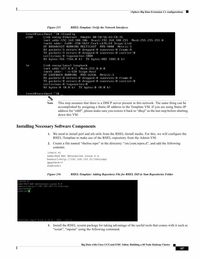
vSphere Big Data Extension 2.1 configurations
Figure 215 RHEL-Template: Verify the Network Interfaces
Note This step assumes that there is a DHCP server present in this network. The same thing can be accomplished by assigning a Static-IP address to the Template VM. If you are using Static-IP address for “eth0”, please make sure you restore it back to “dhcp” as the last step before shutting down this VM.
Installing Necessary Software Components
1. We need to install perl and nfs-utils from the RHEL-Install media. For this, we will configure the RHEL-Template to make use of the RHEL-repository from the Admin-VM.
2. Create a file named “rheliso.repo” in the directory “/etc/yum.repos.d”, and add the following contents.
[rhel6.4]name=Red Hat Enterprise Linux 6.4baseurl=http://192.168.100.51/rhelrepogpgcheck=0enabled=1
Figure 216 RHEL-Template: Adding Repository File for RHEL ISO in Yum Repositories Folder
3. Install the RHEL sysstat package for taking advantage of the useful tools that comes with it such as “iostat”, “mpstat” using the following command.
187Big Data with Cisco UCS and EMC Isilon: Building a 60 Node Hadoop Cluster
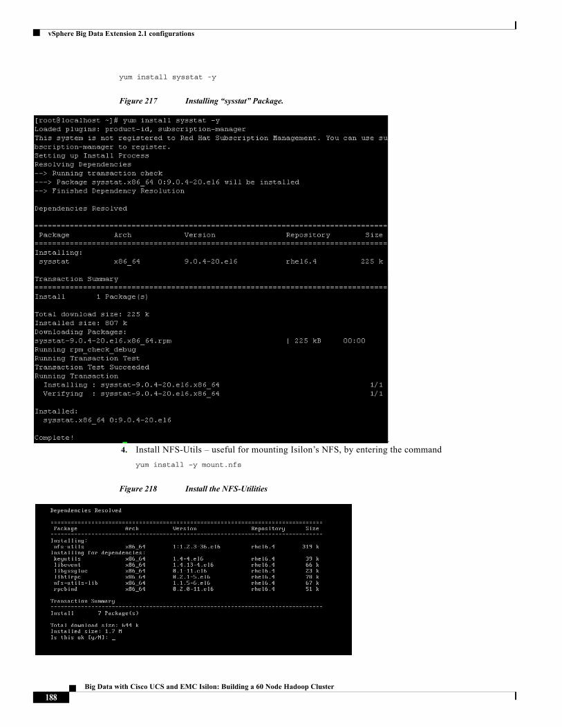
vSphere Big Data Extension 2.1 configurations
yum install sysstat -y
Figure 217 Installing “sysstat” Package.
4. Install NFS-Utils – useful for mounting Isilon’s NFS, by entering the command
yum install –y mount.nfs
Figure 218 Install the NFS-Utilities
188Big Data with Cisco UCS and EMC Isilon: Building a 60 Node Hadoop Cluster
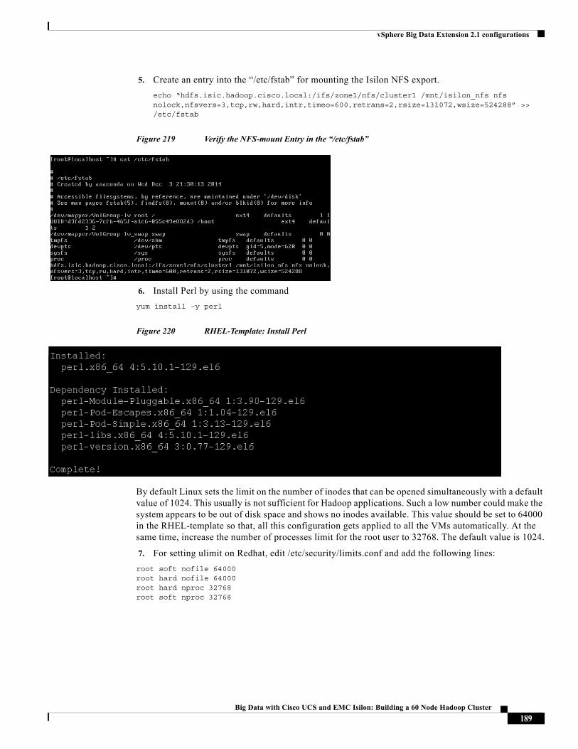
vSphere Big Data Extension 2.1 configurations
5. Create an entry into the “/etc/fstab” for mounting the Isilon NFS export.
echo “hdfs.isic.hadoop.cisco.local:/ifs/zone1/nfs/cluster1 /mnt/isilon_nfs nfs nolock,nfsvers=3,tcp,rw,hard,intr,timeo=600,retrans=2,rsize=131072,wsize=524288” >> /etc/fstab
Figure 219 Verify the NFS-mount Entry in the “/etc/fstab”
6. Install Perl by using the command
yum install –y perl
Figure 220 RHEL-Template: Install Perl
By default Linux sets the limit on the number of inodes that can be opened simultaneously with a default value of 1024. This usually is not sufficient for Hadoop applications. Such a low number could make the system appears to be out of disk space and shows no inodes available. This value should be set to 64000 in the RHEL-template so that, all this configuration gets applied to all the VMs automatically. At the same time, increase the number of processes limit for the root user to 32768. The default value is 1024.
7. For setting ulimit on Redhat, edit /etc/security/limits.conf and add the following lines:
root soft nofile 64000root hard nofile 64000root hard nproc 32768root soft nproc 32768
189Big Data with Cisco UCS and EMC Isilon: Building a 60 Node Hadoop Cluster
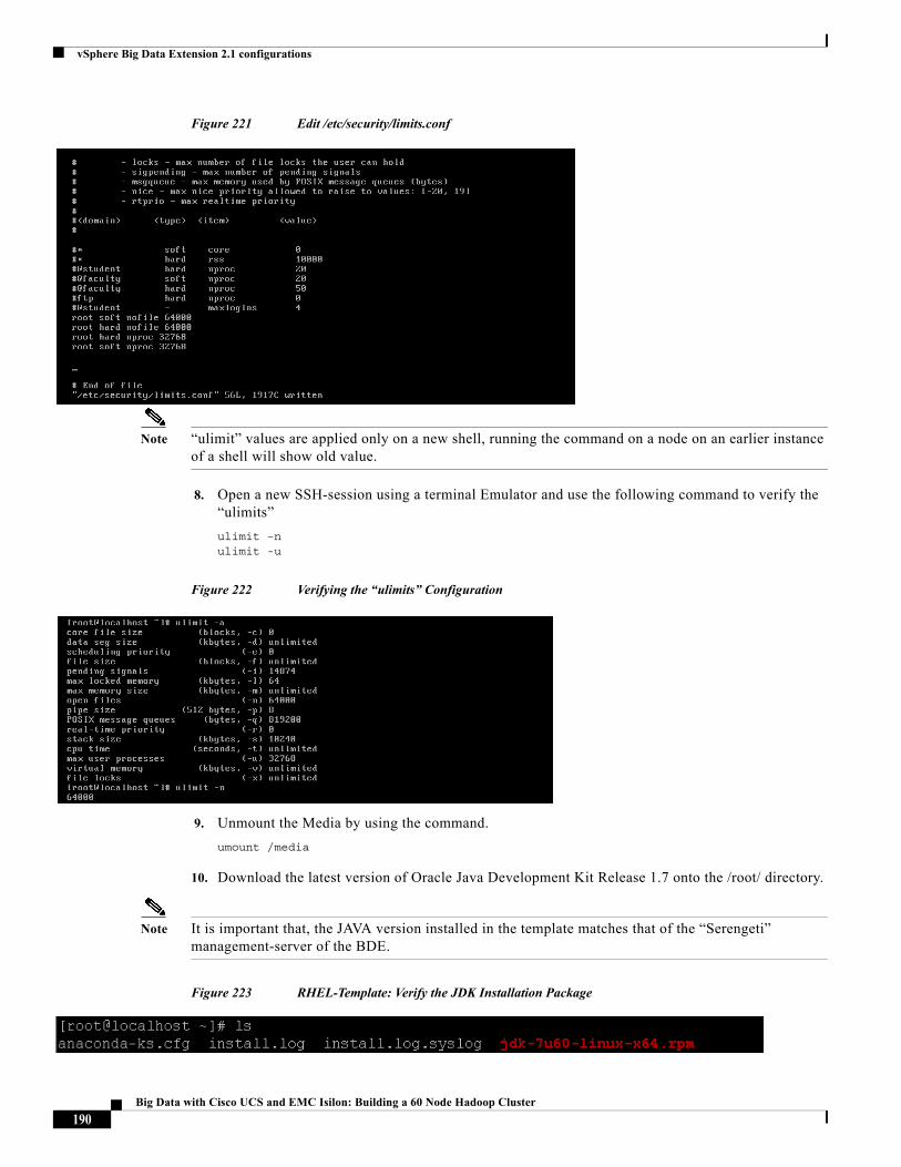
vSphere Big Data Extension 2.1 configurations
Figure 221 Edit /etc/security/limits.conf
Note “ulimit” values are applied only on a new shell, running the command on a node on an earlier instance of a shell will show old value.
8. Open a new SSH-session using a terminal Emulator and use the following command to verify the “ulimits”
ulimit –nulimit -u
Figure 222 Verifying the “ulimits” Configuration
9. Unmount the Media by using the command.
umount /media
10. Download the latest version of Oracle Java Development Kit Release 1.7 onto the /root/ directory.
Note It is important that, the JAVA version installed in the template matches that of the “Serengeti” management-server of the BDE.
Figure 223 RHEL-Template: Verify the JDK Installation Package
190Big Data with Cisco UCS and EMC Isilon: Building a 60 Node Hadoop Cluster
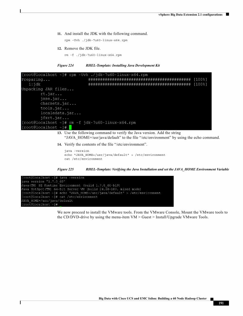
vSphere Big Data Extension 2.1 configurations
11. And install the JDK with the following command.
rpm -Uvh ./jdk-7u60-linux-x64.rpm
12. Remove the JDK file.
rm -f ./jdk-7u60-linux-x64.rpm
Figure 224 RHEL-Template: Installing Java Development Kit
13. Use the following command to verify the Java version. Add the string “JAVA_HOME=/usr/java/default” to the file “/etc/environment” by using the echo command.
14. Verify the contents of the file “/etc/environment”.
java –versionecho "JAVA_HOME=/usr/java/default" > /etc/environmentcat /etc/environment
Figure 225 RHEL-Template: Verifying the Java Installation and set the JAVA_HOME Environment Variable
We now proceed to install the VMware tools. From the VMware Console, Mount the VMware tools to the CD/DVD-drive by using the menu-item VM > Guest > Install/Upgrade VMware Tools.
191Big Data with Cisco UCS and EMC Isilon: Building a 60 Node Hadoop Cluster
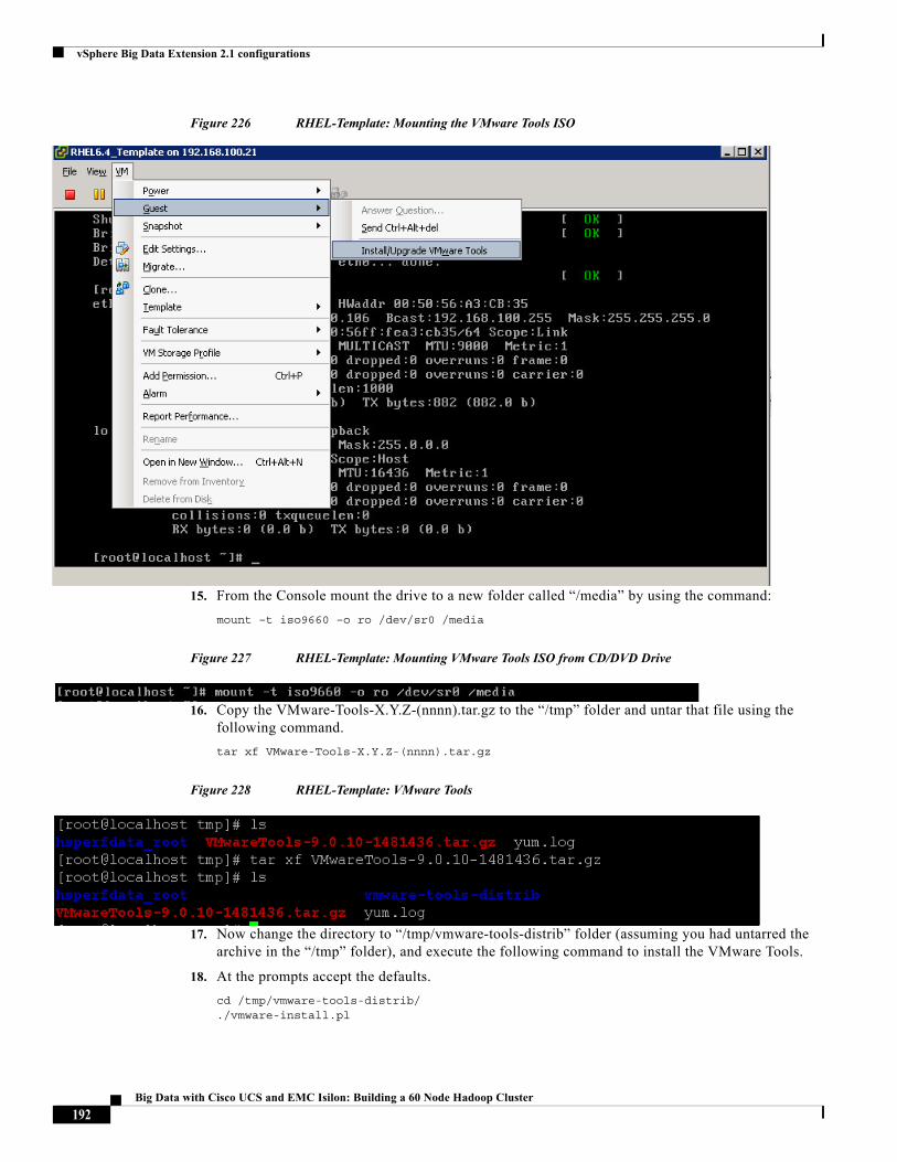
vSphere Big Data Extension 2.1 configurations
Figure 226 RHEL-Template: Mounting the VMware Tools ISO
15. From the Console mount the drive to a new folder called “/media” by using the command:
mount –t iso9660 –o ro /dev/sr0 /media
Figure 227 RHEL-Template: Mounting VMware Tools ISO from CD/DVD Drive
16. Copy the VMware-Tools-X.Y.Z-(nnnn).tar.gz to the “/tmp” folder and untar that file using the following command.
tar xf VMware-Tools-X.Y.Z-(nnnn).tar.gz
Figure 228 RHEL-Template: VMware Tools
17. Now change the directory to “/tmp/vmware-tools-distrib” folder (assuming you had untarred the archive in the “/tmp” folder), and execute the following command to install the VMware Tools.
18. At the prompts accept the defaults.
cd /tmp/vmware-tools-distrib/./vmware-install.pl
192Big Data with Cisco UCS and EMC Isilon: Building a 60 Node Hadoop Cluster

vSphere Big Data Extension 2.1 configurations
Figure 229 RHEL-Template: Executing the VMware Tools Installation Script
19. Look for the successful installation prompt at the end of installation.
Figure 230 RHEL-Template: VMware Tools Successfully Installed
20. Upon completion, unmount the “/media” and delete the VMware tools related files.
Figure 231 RHEL-Template: Delete the VMware Tools Related files and vmware-tools-distrib Directory
Downloading and Installing Custom Scripts from BDE management-server
In this section, we will be downloading custom scripts from the BDE management-server and installing it in the template.
Note This procedure requires the VM to have access to the internet and RHEL repository.
1. Create a director called custos under “/tmp”
2. Download and install the custom scripts from the BDE2.1 management-server i.e. 192.168.100.81.
193Big Data with Cisco UCS and EMC Isilon: Building a 60 Node Hadoop Cluster
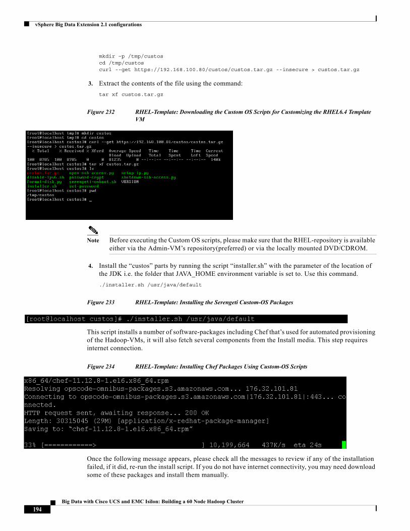
vSphere Big Data Extension 2.1 configurations
mkdir –p /tmp/custoscd /tmp/custoscurl --get https://192.168.100.80/custos/custos.tar.gz --insecure > custos.tar.gz
3. Extract the contents of the file using the command:
tar xf custos.tar.gz
Figure 232 RHEL-Template: Downloading the Custom OS Scripts for Customizing the RHEL6.4 Template VM
Note Before executing the Custom OS scripts, please make sure that the RHEL-repository is available either via the Admin-VM’s repository(preferred) or via the locally mounted DVD/CDROM.
4. Install the “custos” parts by running the script “installer.sh” with the parameter of the location of the JDK i.e. the folder that JAVA_HOME environment variable is set to. Use this command.
./installer.sh /usr/java/default
Figure 233 RHEL-Template: Installing the Serengeti Custom-OS Packages
This script installs a number of software-packages including Chef that’s used for automated provisioning of the Hadoop-VMs, it will also fetch several components from the Install media. This step requires internet connection.
Figure 234 RHEL-Template: Installing Chef Packages Using Custom-OS Scripts
Once the following message appears, please check all the messages to review if any of the installation failed, if it did, re-run the install script. If you do not have internet connectivity, you may need download some of these packages and install them manually.
194Big Data with Cisco UCS and EMC Isilon: Building a 60 Node Hadoop Cluster
vSphere Big Data Extension 2.1 configurations
Figure 235 RHEL-Template: Completion of the Custom-OS Scripts Execution
5. Unmount the RHEL6.4 Installation media. And, remove the custom OS scripts.
umount /media
Figure 236 RHEL-Template: Removing the Custom-OS Script Files
6. Remove the /etc/udev/rules.d/70-persistent-net.rules file to avoid increasing the “eth”-number of the interface while creating the VMs. This must be done before powering down the VM.
rm /etc/udev/rules.d/70-persistent-net.rules
Figure 237 RHEL-Template: Deleting the 70-persistent-net.rules
7. Turn off the Firewall, and verify that the firewall service has been stopped by issuing the following commands:
service iptables stopchkconfig iptables off
Figure 238 RHEL-Template: Disable the Firewall
8. Disable SELinux by setting the value “Disabled” to the variable SELINUX in the config file “/etc/selinux/config.
Note If you had created any snapshots on this VM during the course of the installation, delete them now.
9. Using vSphere Web-Client, edit the Settings of this VM, and click VM-Options tab.
10. Click VMware Tools to expand the options list, and check the checkbox to Synchronize guest time with host i.e. ESXi.
11. On the Virtual Hardware Tab, uncheck the Connected checkbox to disconnect the mounted ISO from the virtual CD/DVD device.
195Big Data with Cisco UCS and EMC Isilon: Building a 60 Node Hadoop Cluster
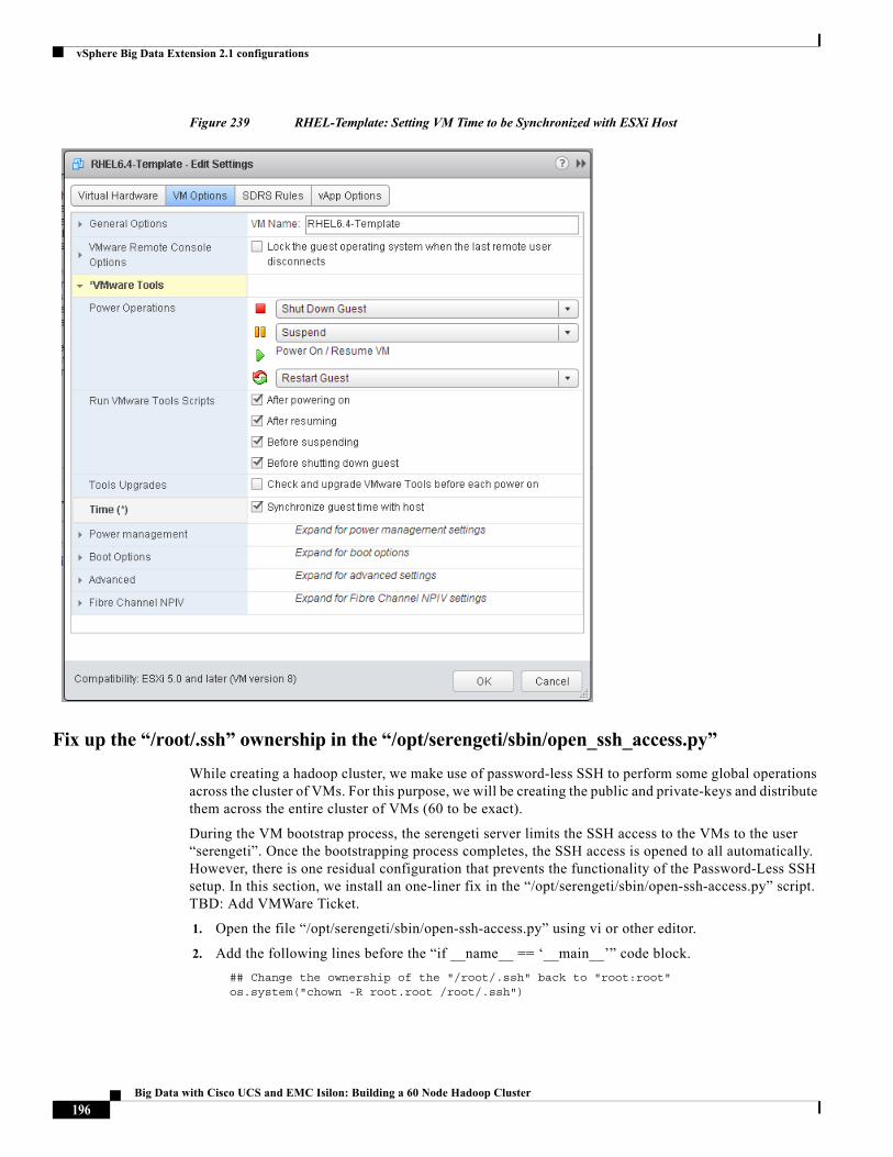
vSphere Big Data Extension 2.1 configurations
Figure 239 RHEL-Template: Setting VM Time to be Synchronized with ESXi Host
Fix up the “/root/.ssh” ownership in the “/opt/serengeti/sbin/open_ssh_access.py”
While creating a hadoop cluster, we make use of password-less SSH to perform some global operations across the cluster of VMs. For this purpose, we will be creating the public and private-keys and distribute them across the entire cluster of VMs (60 to be exact).
During the VM bootstrap process, the serengeti server limits the SSH access to the VMs to the user “serengeti”. Once the bootstrapping process completes, the SSH access is opened to all automatically. However, there is one residual configuration that prevents the functionality of the Password-Less SSH setup. In this section, we install an one-liner fix in the “/opt/serengeti/sbin/open-ssh-access.py” script. TBD: Add VMWare Ticket.
1. Open the file “/opt/serengeti/sbin/open-ssh-access.py” using vi or other editor.
2. Add the following lines before the “if __name__ == ‘__main__’” code block.
## Change the ownership of the "/root/.ssh" back to "root:root" os.system("chown -R root.root /root/.ssh")
196Big Data with Cisco UCS and EMC Isilon: Building a 60 Node Hadoop Cluster
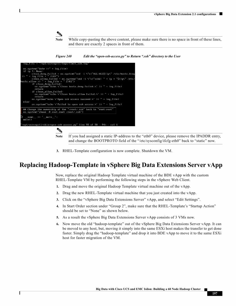
vSphere Big Data Extension 2.1 configurations
Note While copy-pasting the above content, please make sure there is no space in front of these lines, and there are exactly 2 spaces in front of them.
Figure 240 Edit the “open-ssh-access.py” to Return “.ssh” directory to the User
Note If you had assigned a static IP-address to the “eth0” device, please remove the IPADDR entry, and change the BOOTPROTO field of the “/etc/sysconfig/ifcfg-eth0” back to “static” now.
3. RHEL-Template configuration is now complete. Shutdown the VM.
Replacing Hadoop-Template in vSphere Big Data Extensions Server vApp
Now, replace the original Hadoop Template virtual machine of the BDE vApp with the custom RHEL-Template VM by performing the following steps in the vSphere Web Client.
1. Drag and move the original Hadoop Template virtual machine out of the vApp.
2. Drag the new RHEL-Template virtual machine that you just created into the vApp.
3. Click on the “vSphere Big Data Extensions Server” vApp, and select “Edit Settings”.
4. In Start Order section under “Group 2”, make sure that the RHEL-Template’s “Startup Action” should be set to “None” as shown below.
5. As a result the vSphere Big Data Extensions Server vApp consists of 3 VMs now.
6. Now move the old “hadoop-template” out of the vSphere Big Data Extensions Server vApp. It can be moved to any host, but, moving it simply into the same ESXi host makes the transfer to get done faster. Simply drag the “hadoop-template” and drop it into BDE vApp to move it to the same ESXi host for faster migration of the VM.
197Big Data with Cisco UCS and EMC Isilon: Building a 60 Node Hadoop Cluster
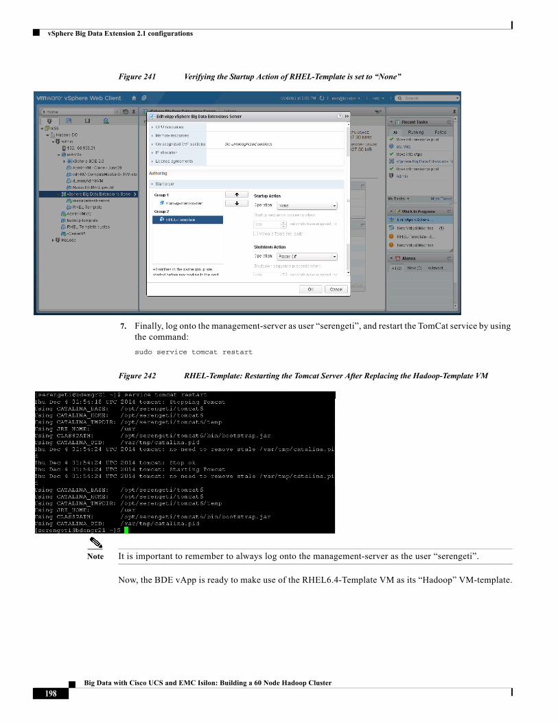
vSphere Big Data Extension 2.1 configurations
Figure 241 Verifying the Startup Action of RHEL-Template is set to “None”
7. Finally, log onto the management-server as user “serengeti”, and restart the TomCat service by using the command:
sudo service tomcat restart
Figure 242 RHEL-Template: Restarting the Tomcat Server After Replacing the Hadoop-Template VM
Note It is important to remember to always log onto the management-server as the user “serengeti”.
Now, the BDE vApp is ready to make use of the RHEL6.4-Template VM as its “Hadoop” VM-template.
198Big Data with Cisco UCS and EMC Isilon: Building a 60 Node Hadoop Cluster
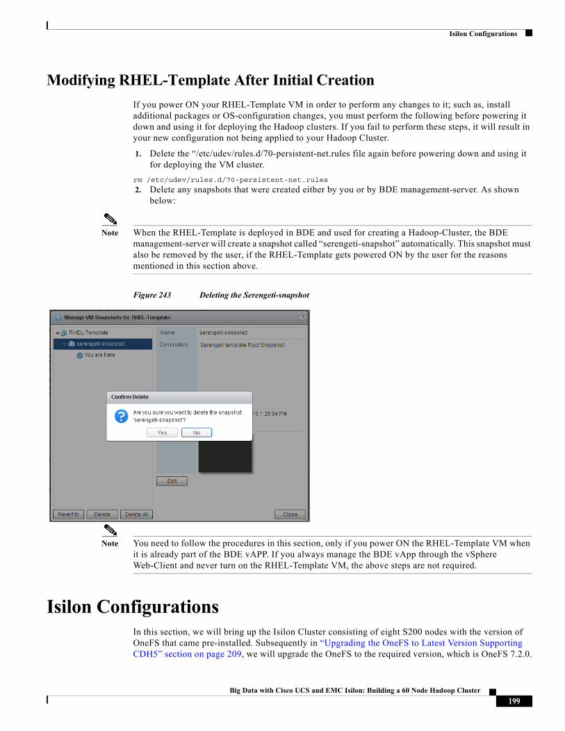
Isilon Configurations
Modifying RHEL-Template After Initial Creation
If you power ON your RHEL-Template VM in order to perform any changes to it; such as, install additional packages or OS-configuration changes, you must perform the following before powering it down and using it for deploying the Hadoop clusters. If you fail to perform these steps, it will result in your new configuration not being applied to your Hadoop Cluster.
1. Delete the “/etc/udev/rules.d/70-persistent-net.rules file again before powering down and using it for deploying the VM cluster.
rm /etc/udev/rules.d/70-persistent-net.rules
2. Delete any snapshots that were created either by you or by BDE management-server. As shown below:
Note When the RHEL-Template is deployed in BDE and used for creating a Hadoop-Cluster, the BDE management-server will create a snapshot called “serengeti-snapshot” automatically. This snapshot must also be removed by the user, if the RHEL-Template gets powered ON by the user for the reasons mentioned in this section above.
Figure 243 Deleting the Serengeti-snapshot
Note You need to follow the procedures in this section, only if you power ON the RHEL-Template VM when it is already part of the BDE vAPP. If you always manage the BDE vApp through the vSphere Web-Client and never turn on the RHEL-Template VM, the above steps are not required.
Isilon ConfigurationsIn this section, we will bring up the Isilon Cluster consisting of eight S200 nodes with the version of OneFS that came pre-installed. Subsequently in “Upgrading the OneFS to Latest Version Supporting CDH5” section on page 209, we will upgrade the OneFS to the required version, which is OneFS 7.2.0.
199Big Data with Cisco UCS and EMC Isilon: Building a 60 Node Hadoop Cluster
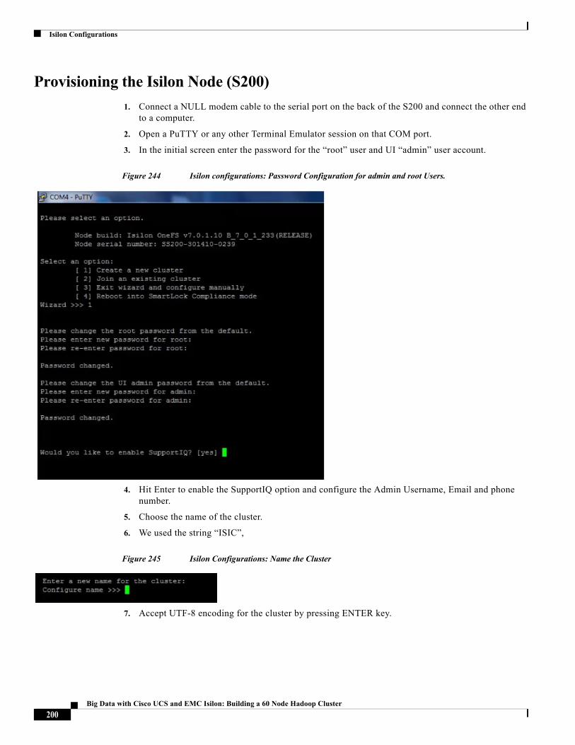
Isilon Configurations
Provisioning the Isilon Node (S200)
1. Connect a NULL modem cable to the serial port on the back of the S200 and connect the other end to a computer.
2. Open a PuTTY or any other Terminal Emulator session on that COM port.
3. In the initial screen enter the password for the “root” user and UI “admin” user account.
Figure 244 Isilon configurations: Password Configuration for admin and root Users.
4. Hit Enter to enable the SupportIQ option and configure the Admin Username, Email and phone number.
5. Choose the name of the cluster.
6. We used the string “ISIC”,
Figure 245 Isilon Configurations: Name the Cluster
7. Accept UTF-8 encoding for the cluster by pressing ENTER key.
200Big Data with Cisco UCS and EMC Isilon: Building a 60 Node Hadoop Cluster
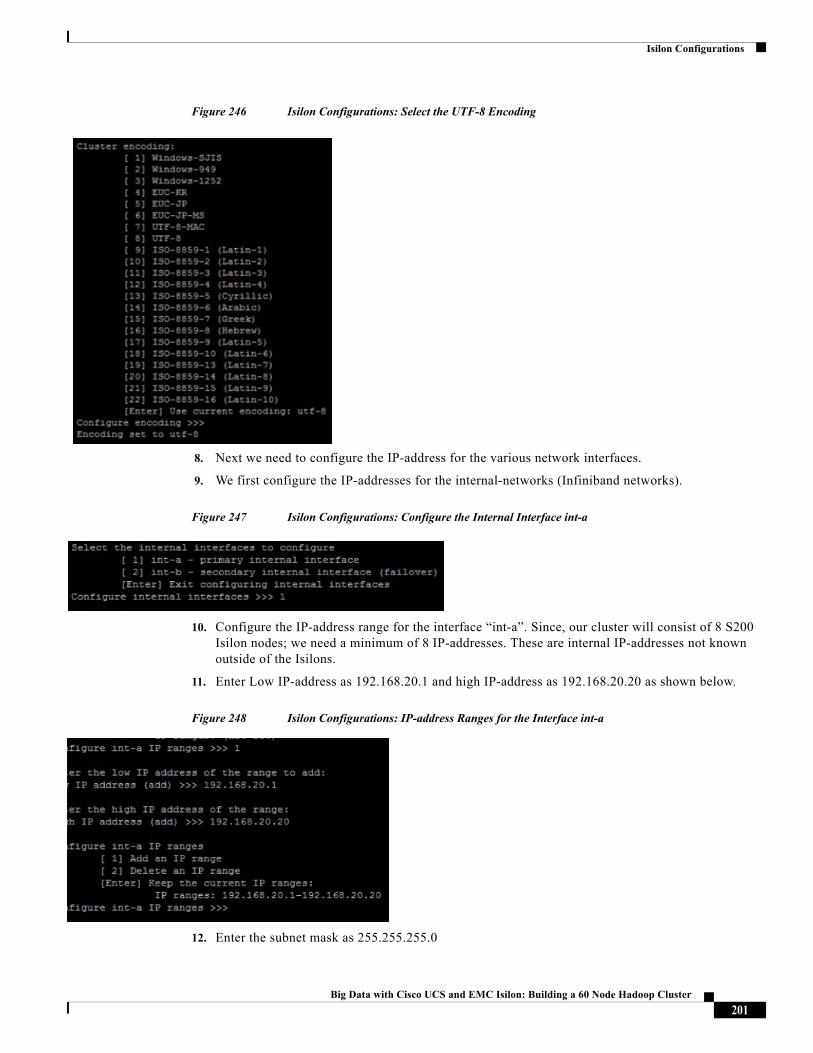
Isilon Configurations
Figure 246 Isilon Configurations: Select the UTF-8 Encoding
8. Next we need to configure the IP-address for the various network interfaces.
9. We first configure the IP-addresses for the internal-networks (Infiniband networks).
Figure 247 Isilon Configurations: Configure the Internal Interface int-a
10. Configure the IP-address range for the interface “int-a”. Since, our cluster will consist of 8 S200 Isilon nodes; we need a minimum of 8 IP-addresses. These are internal IP-addresses not known outside of the Isilons.
11. Enter Low IP-address as 192.168.20.1 and high IP-address as 192.168.20.20 as shown below.
Figure 248 Isilon Configurations: IP-address Ranges for the Interface int-a
12. Enter the subnet mask as 255.255.255.0
201Big Data with Cisco UCS and EMC Isilon: Building a 60 Node Hadoop Cluster
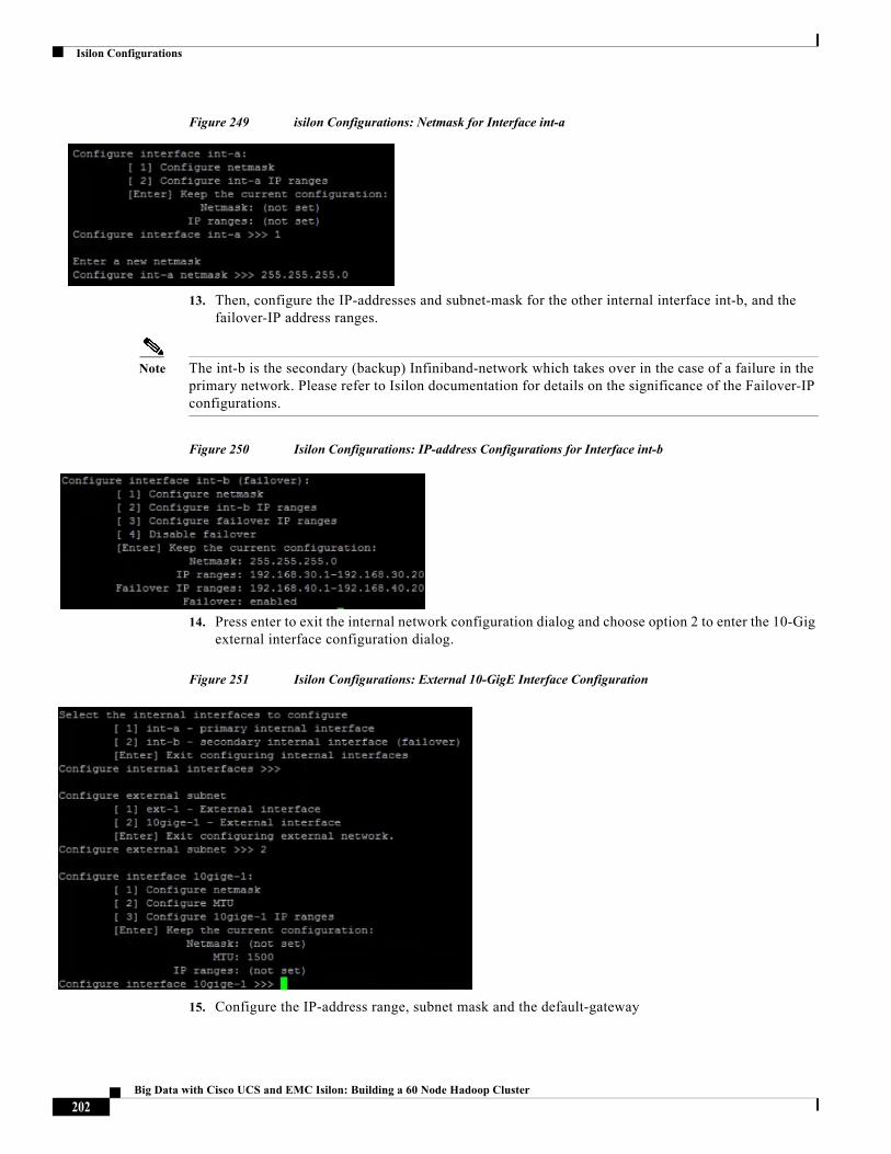
Isilon Configurations
Figure 249 isilon Configurations: Netmask for Interface int-a
13. Then, configure the IP-addresses and subnet-mask for the other internal interface int-b, and the failover-IP address ranges.
Note The int-b is the secondary (backup) Infiniband-network which takes over in the case of a failure in the primary network. Please refer to Isilon documentation for details on the significance of the Failover-IP configurations.
Figure 250 Isilon Configurations: IP-address Configurations for Interface int-b
14. Press enter to exit the internal network configuration dialog and choose option 2 to enter the 10-Gig external interface configuration dialog.
Figure 251 Isilon Configurations: External 10-GigE Interface Configuration
15. Configure the IP-address range, subnet mask and the default-gateway
202Big Data with Cisco UCS and EMC Isilon: Building a 60 Node Hadoop Cluster
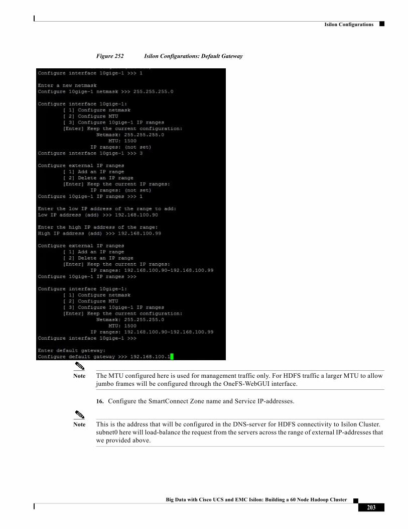
Isilon Configurations
Figure 252 Isilon Configurations: Default Gateway
Note The MTU configured here is used for management traffic only. For HDFS traffic a larger MTU to allow jumbo frames will be configured through the OneFS-WebGUI interface.
16. Configure the SmartConnect Zone name and Service IP-addresses.
Note This is the address that will be configured in the DNS-server for HDFS connectivity to Isilon Cluster. subnet0 here will load-balance the request from the servers across the range of external IP-addresses that we provided above.
203Big Data with Cisco UCS and EMC Isilon: Building a 60 Node Hadoop Cluster
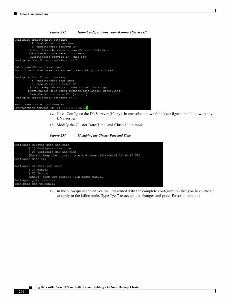
Isilon Configurations
Figure 253 Isilon Configurations: SmartConnect Service IP
17. Next, Configure the DNS server (if any). In our solution, we didn’t configure the Isilon with any DNS server.
18. Modify the Cluster Date/Time, and Cluster Join mode
Figure 254 Modifying the Cluster Date and Time
19. In the subsequent screen you will presented with the complete configuration that you have chosen to apply to the Isilon node. Type “yes” to accept the changes and press Enter to continue.
204Big Data with Cisco UCS and EMC Isilon: Building a 60 Node Hadoop Cluster
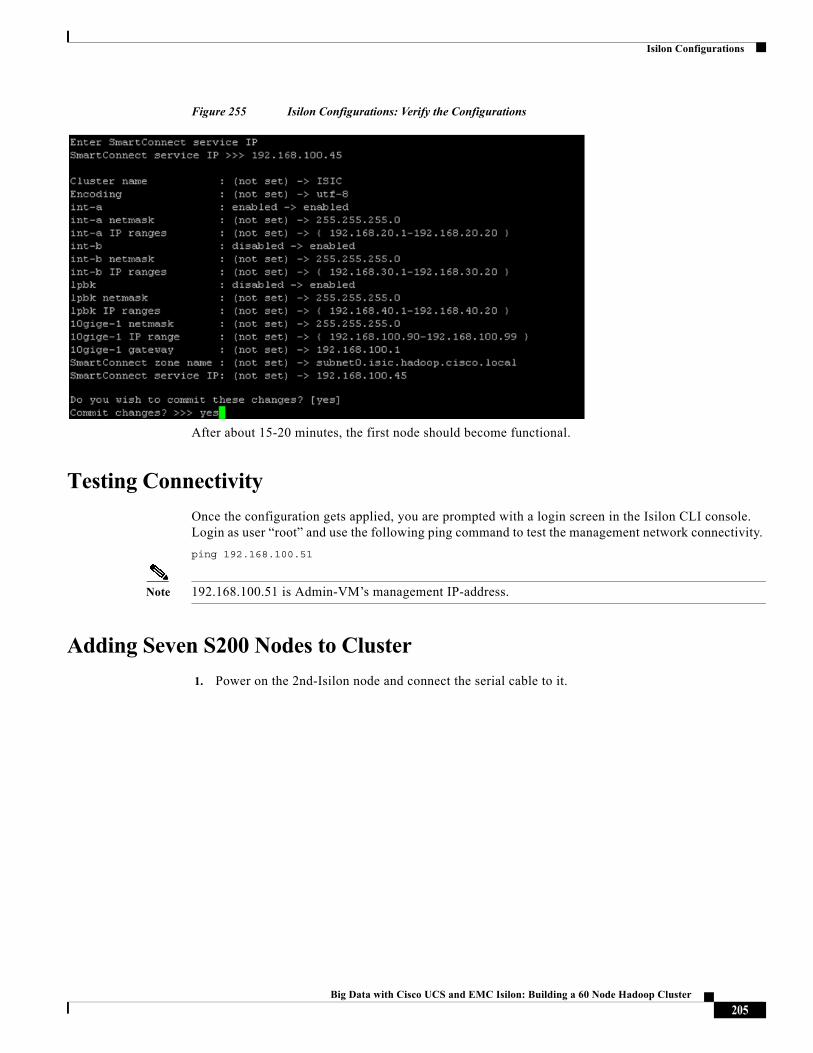
Isilon Configurations
Figure 255 Isilon Configurations: Verify the Configurations
After about 15-20 minutes, the first node should become functional.
Testing Connectivity
Once the configuration gets applied, you are prompted with a login screen in the Isilon CLI console. Login as user “root” and use the following ping command to test the management network connectivity.
ping 192.168.100.51
Note 192.168.100.51 is Admin-VM’s management IP-address.
Adding Seven S200 Nodes to Cluster
1. Power on the 2nd-Isilon node and connect the serial cable to it.
205Big Data with Cisco UCS and EMC Isilon: Building a 60 Node Hadoop Cluster
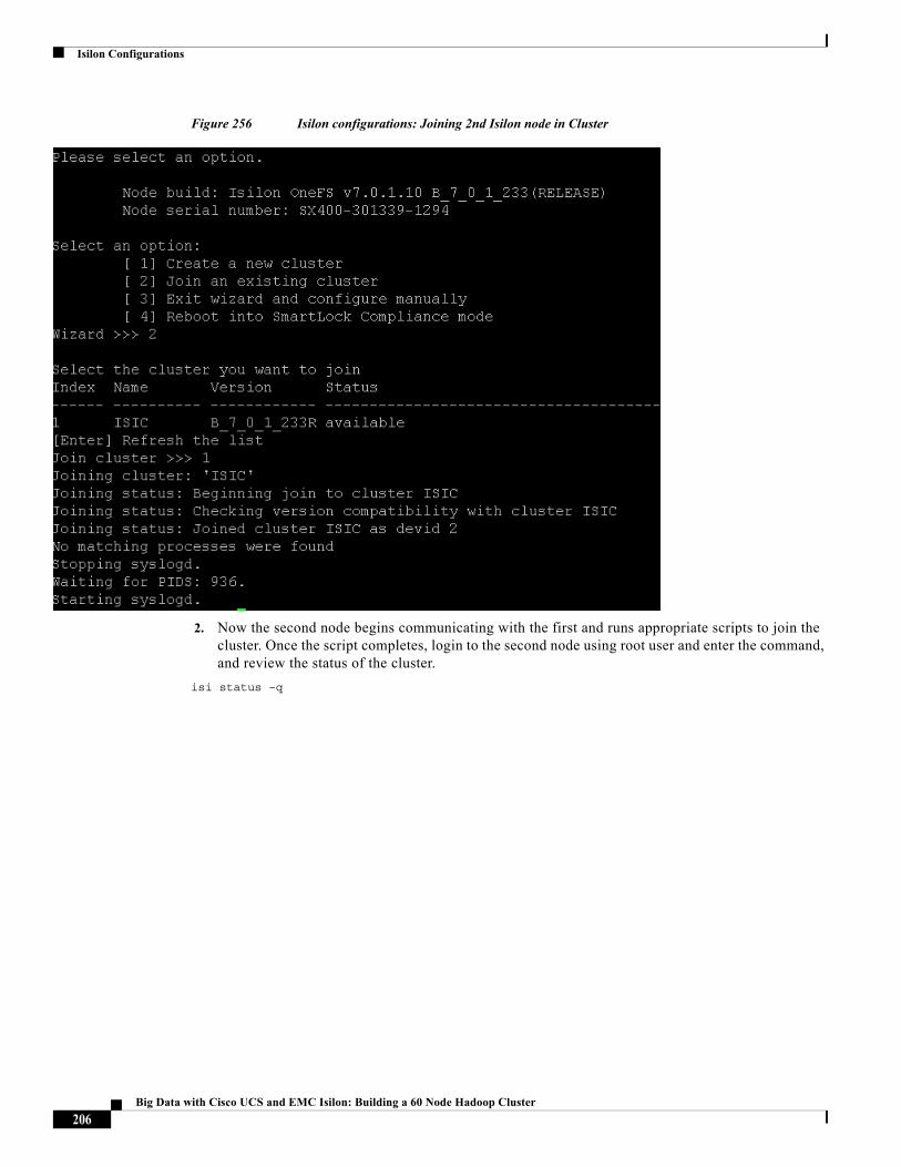
Isilon Configurations
Figure 256 Isilon configurations: Joining 2nd Isilon node in Cluster
2. Now the second node begins communicating with the first and runs appropriate scripts to join the cluster. Once the script completes, login to the second node using root user and enter the command, and review the status of the cluster.
isi status –q
206Big Data with Cisco UCS and EMC Isilon: Building a 60 Node Hadoop Cluster
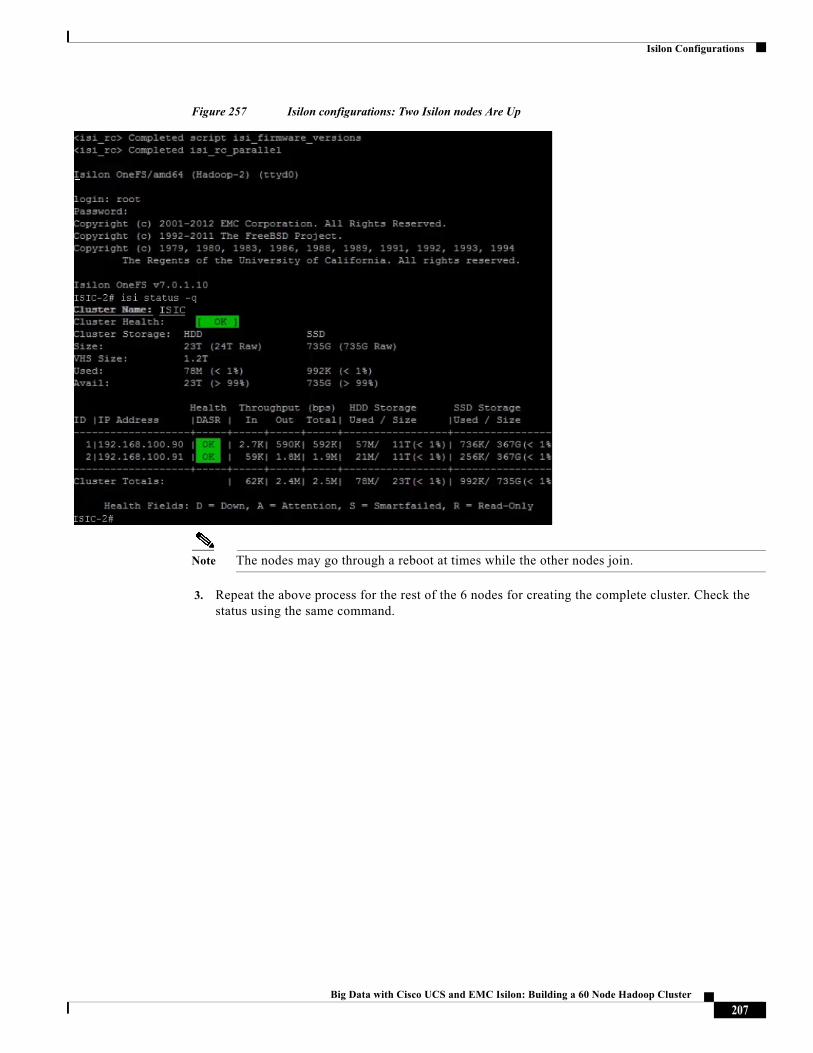
Isilon Configurations
Figure 257 Isilon configurations: Two Isilon nodes Are Up
Note The nodes may go through a reboot at times while the other nodes join.
3. Repeat the above process for the rest of the 6 nodes for creating the complete cluster. Check the status using the same command.
207Big Data with Cisco UCS and EMC Isilon: Building a 60 Node Hadoop Cluster
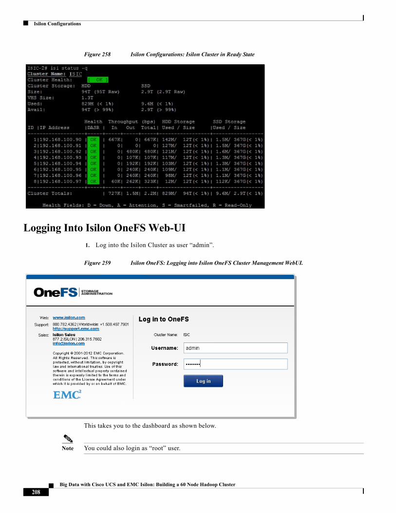
Isilon Configurations
Figure 258 Isilon Configurations: Isilon Cluster in Ready State
Logging Into Isilon OneFS Web-UI
1. Log into the Isilon Cluster as user “admin”.
Figure 259 Isilon OneFS: Logging into Isilon OneFS Cluster Management WebUI.
This takes you to the dashboard as shown below.
Note You could also login as “root” user.
208Big Data with Cisco UCS and EMC Isilon: Building a 60 Node Hadoop Cluster
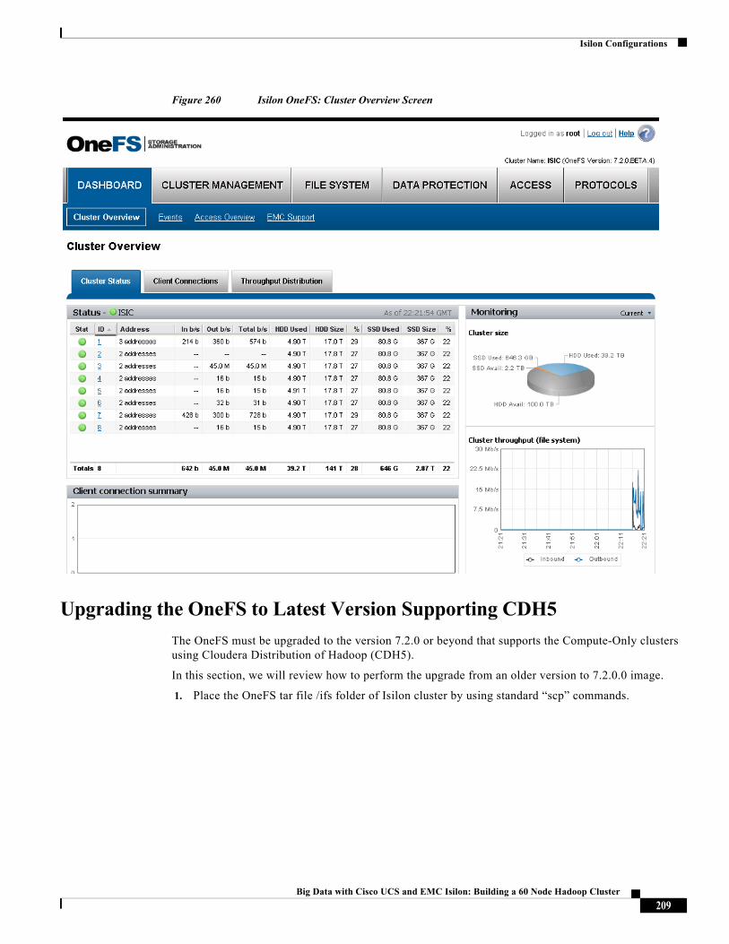
Isilon Configurations
Figure 260 Isilon OneFS: Cluster Overview Screen
Upgrading the OneFS to Latest Version Supporting CDH5
The OneFS must be upgraded to the version 7.2.0 or beyond that supports the Compute-Only clusters using Cloudera Distribution of Hadoop (CDH5).
In this section, we will review how to perform the upgrade from an older version to 7.2.0.0 image.
1. Place the OneFS tar file /ifs folder of Isilon cluster by using standard “scp” commands.
209Big Data with Cisco UCS and EMC Isilon: Building a 60 Node Hadoop Cluster
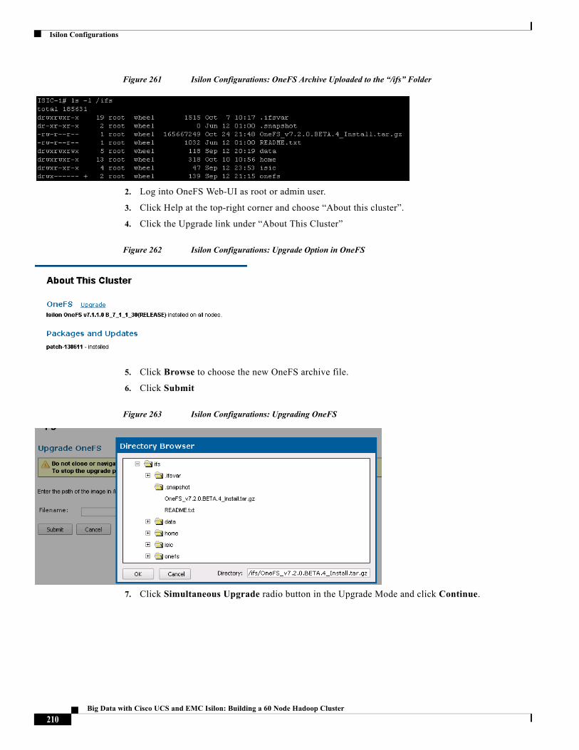
Isilon Configurations
Figure 261 Isilon Configurations: OneFS Archive Uploaded to the “/ifs” Folder
2. Log into OneFS Web-UI as root or admin user.
3. Click Help at the top-right corner and choose “About this cluster”.
4. Click the Upgrade link under “About This Cluster”
Figure 262 Isilon Configurations: Upgrade Option in OneFS
5. Click Browse to choose the new OneFS archive file.
6. Click Submit
Figure 263 Isilon Configurations: Upgrading OneFS
7. Click Simultaneous Upgrade radio button in the Upgrade Mode and click Continue.
210Big Data with Cisco UCS and EMC Isilon: Building a 60 Node Hadoop Cluster
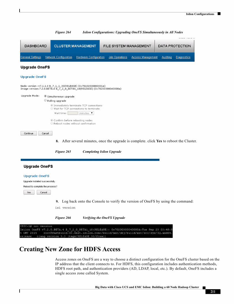
Isilon Configurations
Figure 264 Isilon Configurations: Upgrading OneFS Simultaneously in All Nodes
8. After several minutes, once the upgrade is complete. click Yes to reboot the Cluster.
Figure 265 Completing Isilon Upgrade
9. Log back onto the Console to verify the version of OneFS by using the command:
isi version
Figure 266 Verifying the OneFS Upgrade
Creating New Zone for HDFS Access
Access zones on OneFS are a way to choose a distinct configuration for the OneFS cluster based on the IP address that the client connects to. For HDFS, this configuration includes authentication methods, HDFS root path, and authentication providers (AD, LDAP, local, etc.). By default, OneFS includes a single access zone called System.
211Big Data with Cisco UCS and EMC Isilon: Building a 60 Node Hadoop Cluster
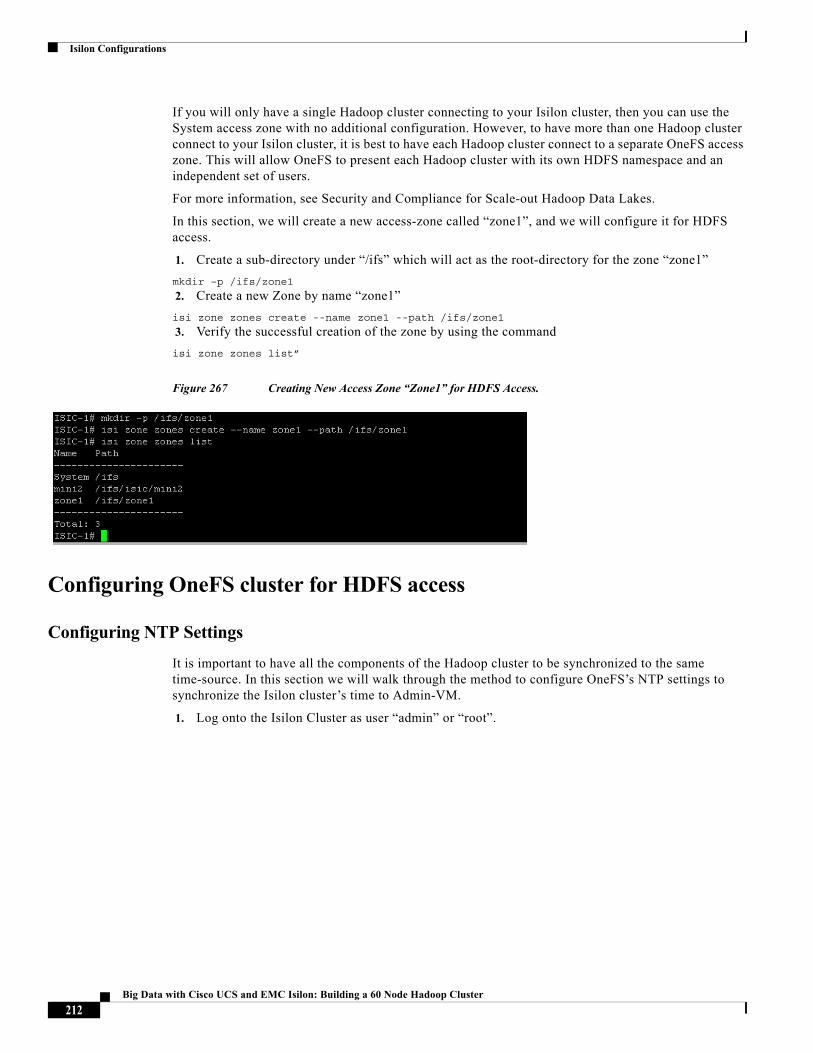
Isilon Configurations
If you will only have a single Hadoop cluster connecting to your Isilon cluster, then you can use the System access zone with no additional configuration. However, to have more than one Hadoop cluster connect to your Isilon cluster, it is best to have each Hadoop cluster connect to a separate OneFS access zone. This will allow OneFS to present each Hadoop cluster with its own HDFS namespace and an independent set of users.
For more information, see Security and Compliance for Scale-out Hadoop Data Lakes.
In this section, we will create a new access-zone called “zone1”, and we will configure it for HDFS access.
1. Create a sub-directory under “/ifs” which will act as the root-directory for the zone “zone1”
mkdir –p /ifs/zone1
2. Create a new Zone by name “zone1”
isi zone zones create --name zone1 --path /ifs/zone1
3. Verify the successful creation of the zone by using the command
isi zone zones list”
Figure 267 Creating New Access Zone “Zone1” for HDFS Access.
Configuring OneFS cluster for HDFS access
Configuring NTP Settings
It is important to have all the components of the Hadoop cluster to be synchronized to the same time-source. In this section we will walk through the method to configure OneFS’s NTP settings to synchronize the Isilon cluster’s time to Admin-VM.
1. Log onto the Isilon Cluster as user “admin” or “root”.
212Big Data with Cisco UCS and EMC Isilon: Building a 60 Node Hadoop Cluster
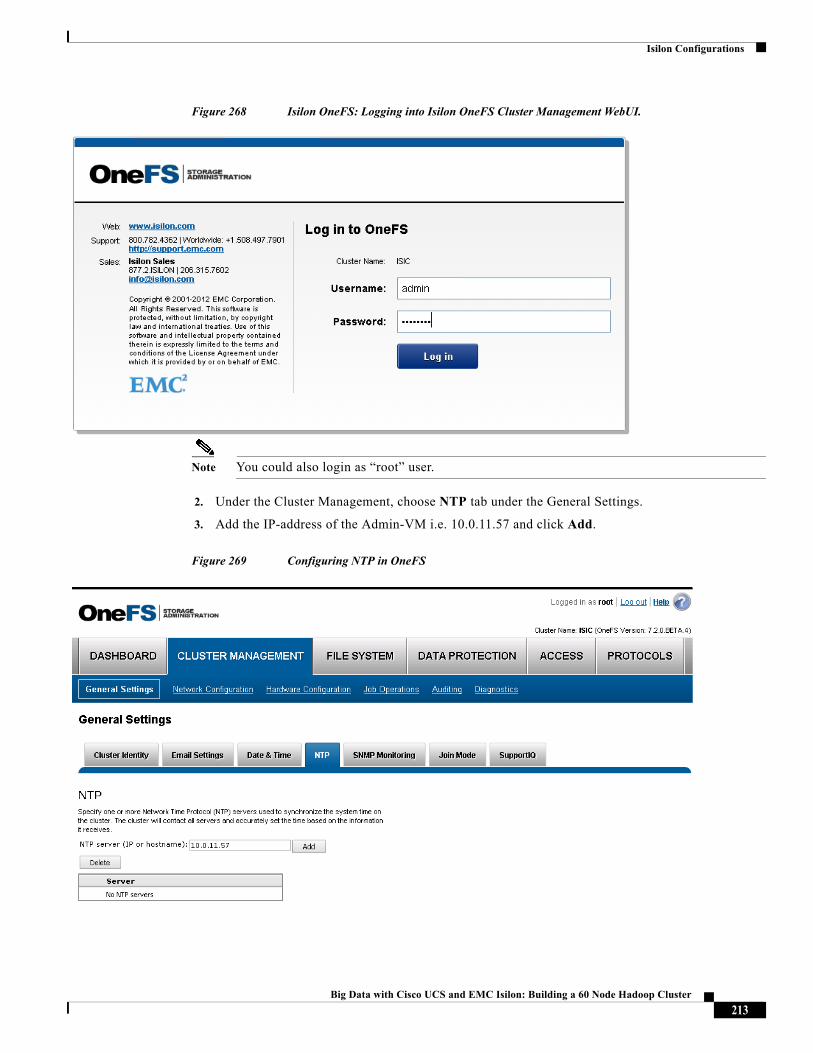
Isilon Configurations
Figure 268 Isilon OneFS: Logging into Isilon OneFS Cluster Management WebUI.
Note You could also login as “root” user.
2. Under the Cluster Management, choose NTP tab under the General Settings.
3. Add the IP-address of the Admin-VM i.e. 10.0.11.57 and click Add.
Figure 269 Configuring NTP in OneFS
213Big Data with Cisco UCS and EMC Isilon: Building a 60 Node Hadoop Cluster
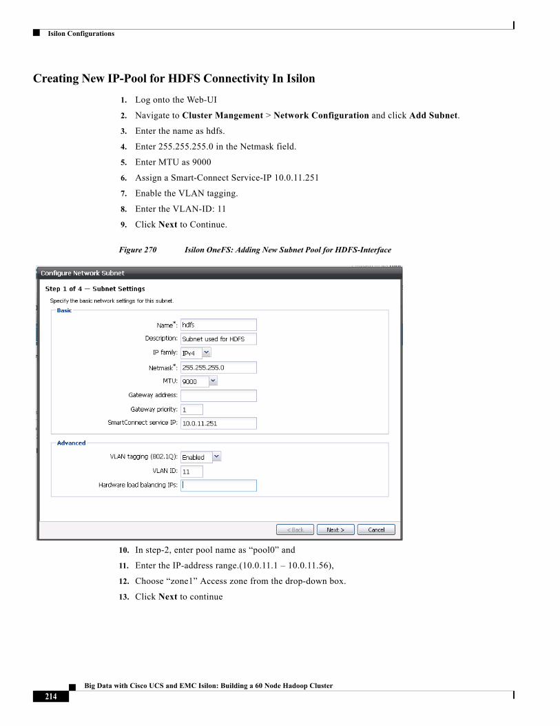
Isilon Configurations
Creating New IP-Pool for HDFS Connectivity In Isilon
1. Log onto the Web-UI
2. Navigate to Cluster Mangement > Network Configuration and click Add Subnet.
3. Enter the name as hdfs.
4. Enter 255.255.255.0 in the Netmask field.
5. Enter MTU as 9000
6. Assign a Smart-Connect Service-IP 10.0.11.251
7. Enable the VLAN tagging.
8. Enter the VLAN-ID: 11
9. Click Next to Continue.
Figure 270 Isilon OneFS: Adding New Subnet Pool for HDFS-Interface
10. In step-2, enter pool name as “pool0” and
11. Enter the IP-address range.(10.0.11.1 – 10.0.11.56),
12. Choose “zone1” Access zone from the drop-down box.
13. Click Next to continue
214Big Data with Cisco UCS and EMC Isilon: Building a 60 Node Hadoop Cluster
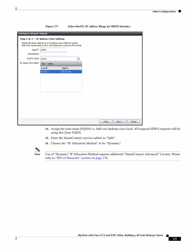
Isilon Configurations
Figure 271 Isilon OneFS: IP Address Range for HDFS-Interface
14. Assign the zone name (FQDN) i.e. hdfs.isic.hadoop.cisco.local. All requests HDFS-requests will be using this Zone FQDN.
15. Enter the SmartConnect service subnet as “hdfs”.
16. Choose the “IP Allocation Method” to be “Dynamic”.
Note Use of “Dynamic” IP Allocation Method requires additional “SmartConnect Advanced” License. Please refer to “Bill of Materials” section on page 278.
215Big Data with Cisco UCS and EMC Isilon: Building a 60 Node Hadoop Cluster

Isilon Configurations
Figure 272 Isilon OneFS: SmartConnect Settings Configuration
17. Set Aggregation Mode to be Active/Passive Failover type.
18. Under the “Available interfaces” column, choose all the interfaces that matches the pattern “10gige-agg-*” and click to add them to the “Interfaces in current subnet” column.
19. Click Submit.
216Big Data with Cisco UCS and EMC Isilon: Building a 60 Node Hadoop Cluster
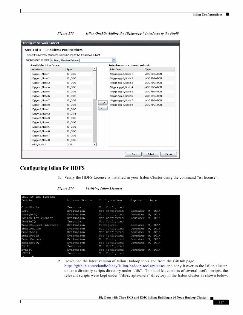
Isilon Configurations
Figure 273 Isilon OneFS: Adding the 10gige-agg-* Interfaces to the Pool0
Configuring Isilon for HDFS
1. Verify the HDFS License is installed in your Isilon Cluster using the command “isi license”.
Figure 274 Verifying Isilon Licenses
2. Download the latest version of Isilon Hadoop tools and from the GitHub page https://github.com/claudiofahey/isilon-hadoop-tools/releases and copy it over to the Isilon cluster under a directory scripts directory under “/ifs”. This tool-kit consists of several useful scripts, the relevant scripts were kept under “/ifs/scripts/onefs” directory in the Isilon cluster as shown below.
217Big Data with Cisco UCS and EMC Isilon: Building a 60 Node Hadoop Cluster
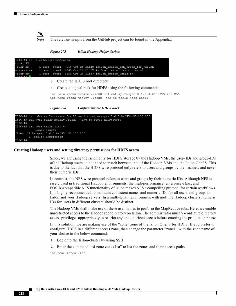
Isilon Configurations
Note The relevant scripts from the GitHub project can be found in the Appendix.
Figure 275 Isilon Hadoop Helper Scripts
3. Create the HDFS root directory.
4. Create a logical rack for HDFS using the following commands:
isi hdfs racks create /rack0 –client-ip-ranges 0.0.0.0-255.255.255.255isi hdfs racks modify /rack0 –add-ip-pools hdfs:pool0
Figure 276 Configuring the HDFS Rack
Creating Hadoop users and setting directory permissions for HDFS access
Since, we are using the Isilon only for HDFS storage by the Hadoop VMs, the user- IDs and group-IDs of the Hadoop-users do not need to match between that of the Hadoop-VMs and the Isilon OneFS. This is due to the fact that the HDFS wire protocol only refers to users and groups by their names, and never their numeric IDs.
In contrast, the NFS wire protocol refers to users and groups by their numeric IDs. Although NFS is rarely used in traditional Hadoop environments, the high-performance, enterprise-class, and POSIX-compatible NFS functionality of Isilon makes NFS a compelling protocol for certain workflows. It is highly recommended to maintain consistent names and numeric IDs for all users and groups on Isilon and your Hadoop servers. In a multi-tenant environment with multiple Hadoop clusters, numeric IDs for users in different clusters should be distinct.
The Hadoop VMs shall make use of these user names to perform the MapReduce jobs. Here, we enable unrestricted access to the Hadoop root directory on Isilon. The administrator must re-configure directory access privileges appropriately to restrict any unauthorized access before entering the production phase.
In this solution, we are making use of the “zone” zone of the Isilon OneFS for HDFS. If you prefer to configure HDFS in a different access zone, then change the parameter “zone1” with the zone name of your choice in the below commands.
1. Log onto the Isilon-cluster by using SSH
2. Enter the command “isi zone zones list” to list the zones and their access paths
isi zone zones list
218Big Data with Cisco UCS and EMC Isilon: Building a 60 Node Hadoop Cluster
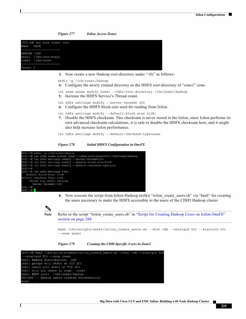
Isilon Configurations
Figure 277 Isilon Access Zones
3. Now create a new Hadoop root-directory under “/ifs” as follows:
mkdir –p /ifs/zone1/hadoop
4. Configure the newly created directory as the HDFS root-directory of “zone1” zone.
isi zone zones modify zone1 --hdfs-root-directory /ifs/zone1/hadoop
5. Increase the HDFS Service’s Thread count.
isi hdfs settings modify --server-threads 256
6. Configure the HDFS block-size used for reading from Isilon.
isi hdfs settings modify --default-block-size 512M.
7. Disable the HDFS checksum. This checksum is never stored in the Isilon, since Isilon performs its own advanced checksum calculations, it is safe to disable the HDFS checksum here, and it might also help increase Isilon performance.
isi hdfs settings modify --default-checksum-type=none
Figure 278 Initial HDFS Configuration in OneFS
8. Now execute the script from Isilon-Hadoop toolkit “isilon_create_users.sh” via “bash” for creating the users necessary to make the HDFS accessible to the users of the CDH5 Hadoop cluster
Note Refer to the script “Isilon_create_users.sh” in “Script for Creating Hadoop Users on Isilon OneFS” section on page 284
bash /ifs/scripts/onefs/isilon_create_users.sh --dist cdh --startgid 501 --startuid 501 --zone zone1
Figure 279 Creating the CDH-Specific Users in Zone1
219Big Data with Cisco UCS and EMC Isilon: Building a 60 Node Hadoop Cluster
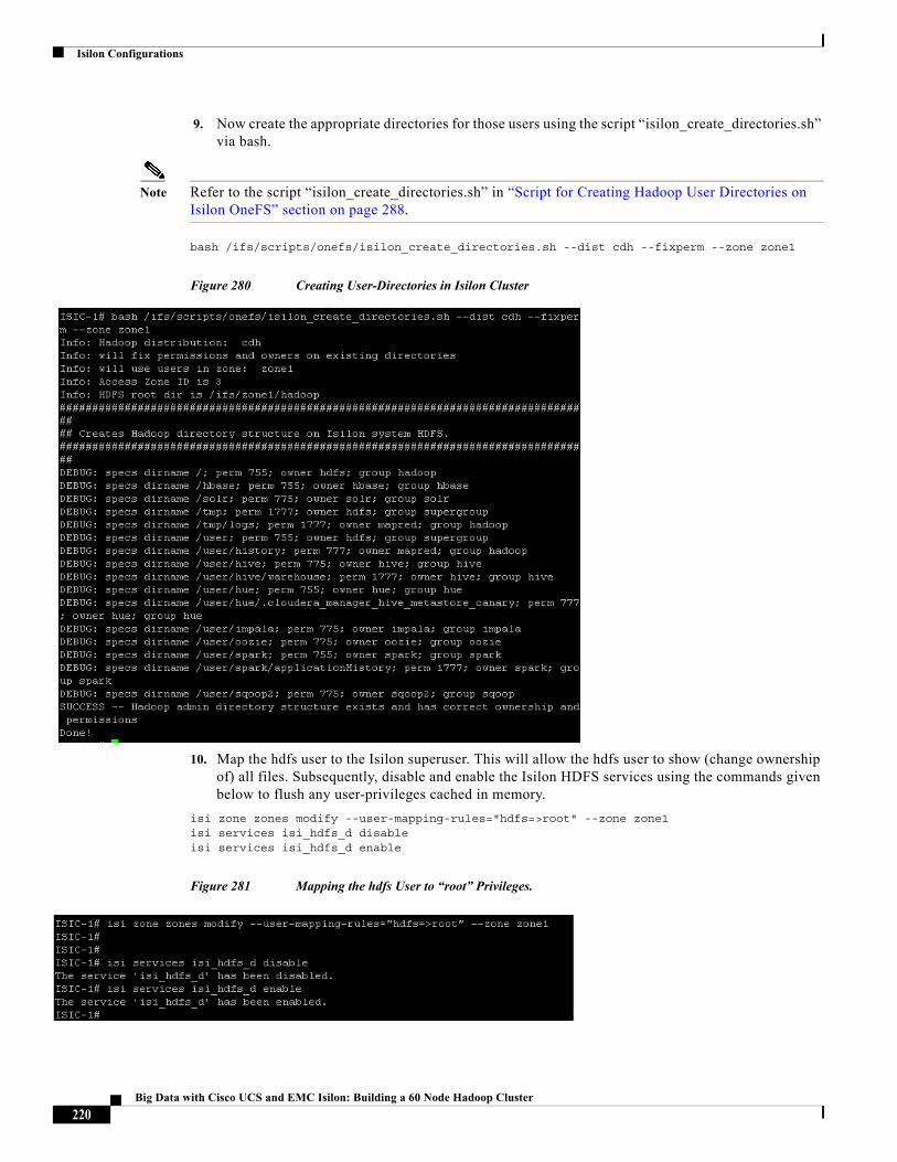
Isilon Configurations
9. Now create the appropriate directories for those users using the script “isilon_create_directories.sh” via bash.
Note Refer to the script “isilon_create_directories.sh” in “Script for Creating Hadoop User Directories on Isilon OneFS” section on page 288.
bash /ifs/scripts/onefs/isilon_create_directories.sh --dist cdh --fixperm --zone zone1
Figure 280 Creating User-Directories in Isilon Cluster
10. Map the hdfs user to the Isilon superuser. This will allow the hdfs user to show (change ownership of) all files. Subsequently, disable and enable the Isilon HDFS services using the commands given below to flush any user-privileges cached in memory.
isi zone zones modify --user-mapping-rules="hdfs=>root" --zone zone1isi services isi_hdfs_d disableisi services isi_hdfs_d enable
Figure 281 Mapping the hdfs User to “root” Privileges.
220Big Data with Cisco UCS and EMC Isilon: Building a 60 Node Hadoop Cluster
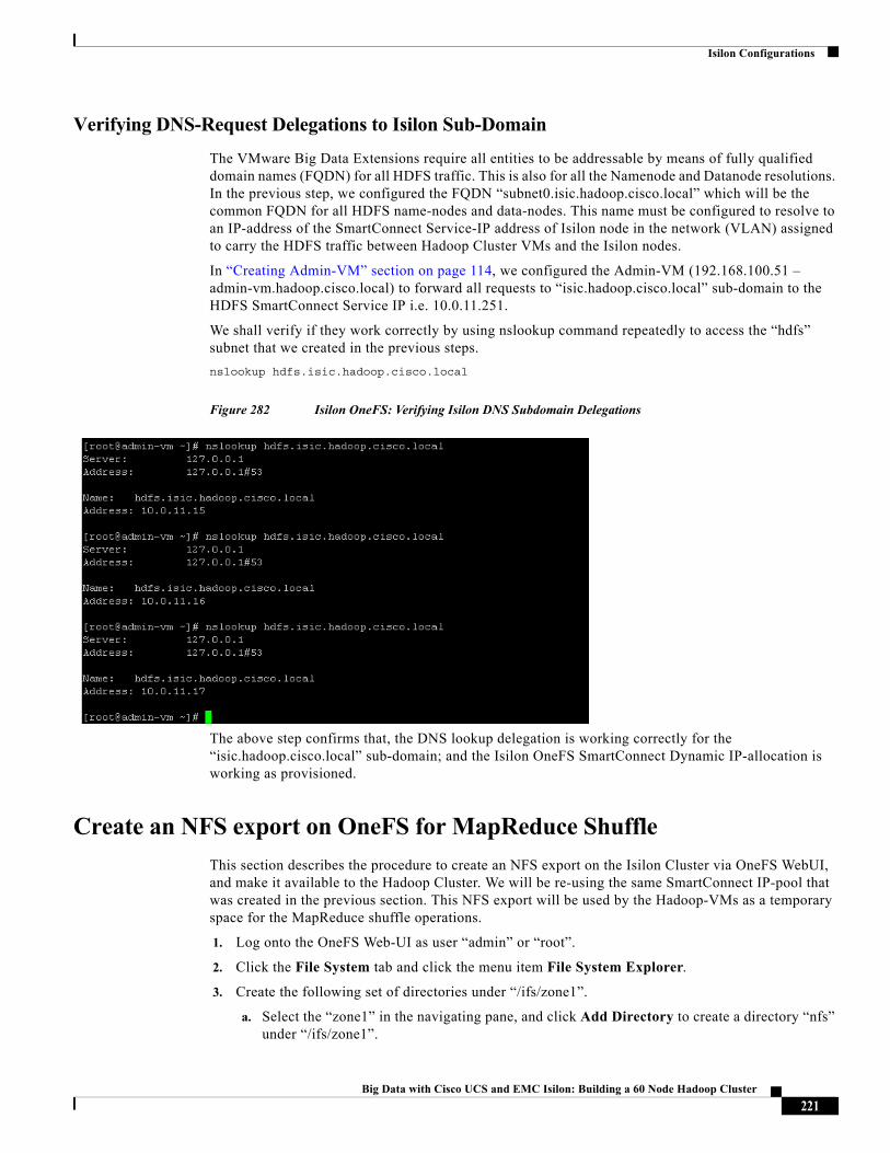
Isilon Configurations
Verifying DNS-Request Delegations to Isilon Sub-Domain
The VMware Big Data Extensions require all entities to be addressable by means of fully qualified domain names (FQDN) for all HDFS traffic. This is also for all the Namenode and Datanode resolutions. In the previous step, we configured the FQDN “subnet0.isic.hadoop.cisco.local” which will be the common FQDN for all HDFS name-nodes and data-nodes. This name must be configured to resolve to an IP-address of the SmartConnect Service-IP address of Isilon node in the network (VLAN) assigned to carry the HDFS traffic between Hadoop Cluster VMs and the Isilon nodes.
In “Creating Admin-VM” section on page 114, we configured the Admin-VM (192.168.100.51 – admin-vm.hadoop.cisco.local) to forward all requests to “isic.hadoop.cisco.local” sub-domain to the HDFS SmartConnect Service IP i.e. 10.0.11.251.
We shall verify if they work correctly by using nslookup command repeatedly to access the “hdfs” subnet that we created in the previous steps.
nslookup hdfs.isic.hadoop.cisco.local
Figure 282 Isilon OneFS: Verifying Isilon DNS Subdomain Delegations
The above step confirms that, the DNS lookup delegation is working correctly for the “isic.hadoop.cisco.local” sub-domain; and the Isilon OneFS SmartConnect Dynamic IP-allocation is working as provisioned.
Create an NFS export on OneFS for MapReduce Shuffle
This section describes the procedure to create an NFS export on the Isilon Cluster via OneFS WebUI, and make it available to the Hadoop Cluster. We will be re-using the same SmartConnect IP-pool that was created in the previous section. This NFS export will be used by the Hadoop-VMs as a temporary space for the MapReduce shuffle operations.
1. Log onto the OneFS Web-UI as user “admin” or “root”.
2. Click the File System tab and click the menu item File System Explorer.
3. Create the following set of directories under “/ifs/zone1”.
a. Select the “zone1” in the navigating pane, and click Add Directory to create a directory “nfs” under “/ifs/zone1”.
221Big Data with Cisco UCS and EMC Isilon: Building a 60 Node Hadoop Cluster
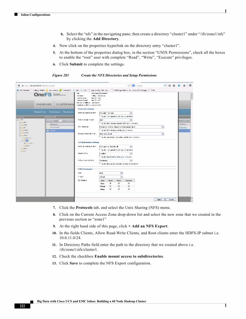
Isilon Configurations
b. Select the “nfs” in the navigating pane; then create a directory “cluster1” under “/ifs/zone1/nfs” by clicking the Add Directory.
4. Now click on the properties hyperlink on the directory entry “cluster1”.
5. At the bottom of the properties dialog box, in the section “UNIX Permissions”, check all the boxes to enable the “root” user with complete “Read”, “Write”, “Execute” privileges.
6. Click Submit to complete the settings.
Figure 283 Create the NFS Directories and Setup Permissions
7. Click the Protocols tab, and select the Unix Sharing (NFS) menu.
8. Click on the Current Access Zone drop-down list and select the new zone that we created in the previous section as “zone1”
9. At the right hand side of this page, click + Add an NFS Export.
10. In the fields Clients, Allow Read-Write Clients, and Root clients enter the HDFS-IP subnet i.e. 10.0.11.0/24.
11. In Directory Paths field enter the path to the directory that we created above i.e. /ifs/zone1/nfs/cluster1.
12. Check the checkbox Enable mount access to subdirectories.
13. Click Save to complete the NFS Export configuration.
222Big Data with Cisco UCS and EMC Isilon: Building a 60 Node Hadoop Cluster
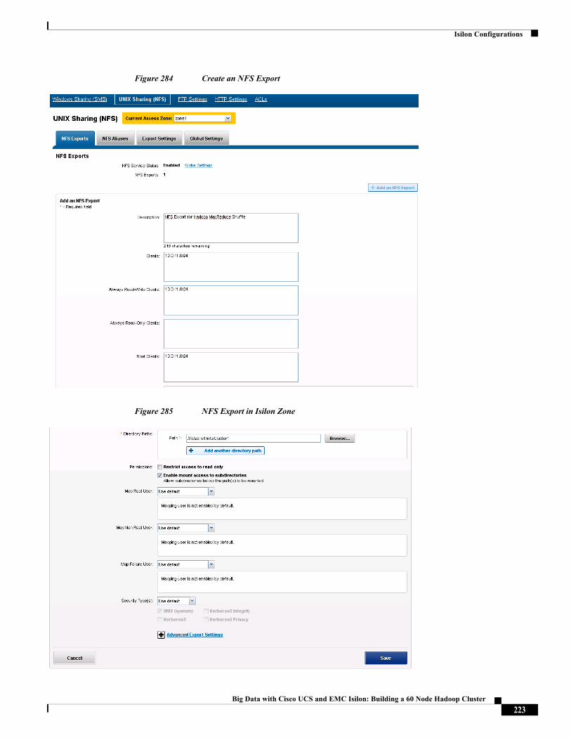
Isilon Configurations
Figure 284 Create an NFS Export
Figure 285 NFS Export in Isilon Zone
223Big Data with Cisco UCS and EMC Isilon: Building a 60 Node Hadoop Cluster
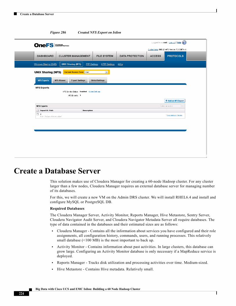
Create a Database Server
Figure 286 Created NFS Export on Isilon
Create a Database ServerThis solution makes use of Cloudera Manager for creating a 60-node Hadoop cluster. For any cluster larger than a few nodes, Cloudera Manager requires an external database server for managing number of its databases.
For this, we will create a new VM on the Admin DRS cluster. We will install RHEL6.4 and install and configure MySQL or PostgreSQL DB.
Required Databases
The Cloudera Manager Server, Activity Monitor, Reports Manager, Hive Metastore, Sentry Server, Cloudera Navigator Audit Server, and Cloudera Navigator Metadata Server all require databases. The type of data contained in the databases and their estimated sizes are as follows:
• Cloudera Manager - Contains all the information about services you have configured and their role assignments, all configuration history, commands, users, and running processes. This relatively small database (<100 MB) is the most important to back up.
• Activity Monitor - Contains information about past activities. In large clusters, this database can grow large. Configuring an Activity Monitor database is only necessary if a MapReduce service is deployed.
• Reports Manager - Tracks disk utilization and processing activities over time. Medium-sized.
• Hive Metastore - Contains Hive metadata. Relatively small.
224Big Data with Cisco UCS and EMC Isilon: Building a 60 Node Hadoop Cluster
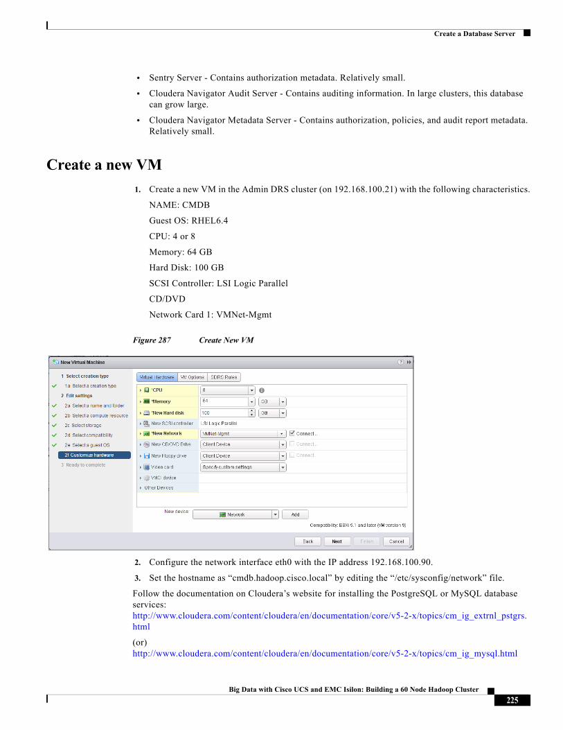
Create a Database Server
• Sentry Server - Contains authorization metadata. Relatively small.
• Cloudera Navigator Audit Server - Contains auditing information. In large clusters, this database can grow large.
• Cloudera Navigator Metadata Server - Contains authorization, policies, and audit report metadata. Relatively small.
Create a new VM
1. Create a new VM in the Admin DRS cluster (on 192.168.100.21) with the following characteristics.
NAME: CMDB
Guest OS: RHEL6.4
CPU: 4 or 8
Memory: 64 GB
Hard Disk: 100 GB
SCSI Controller: LSI Logic Parallel
CD/DVD
Network Card 1: VMNet-Mgmt
Figure 287 Create New VM
2. Configure the network interface eth0 with the IP address 192.168.100.90.
3. Set the hostname as “cmdb.hadoop.cisco.local” by editing the “/etc/sysconfig/network” file.
Follow the documentation on Cloudera’s website for installing the PostgreSQL or MySQL database services: http://www.cloudera.com/content/cloudera/en/documentation/core/v5-2-x/topics/cm_ig_extrnl_pstgrs.html
(or) http://www.cloudera.com/content/cloudera/en/documentation/core/v5-2-x/topics/cm_ig_mysql.html
225Big Data with Cisco UCS and EMC Isilon: Building a 60 Node Hadoop Cluster
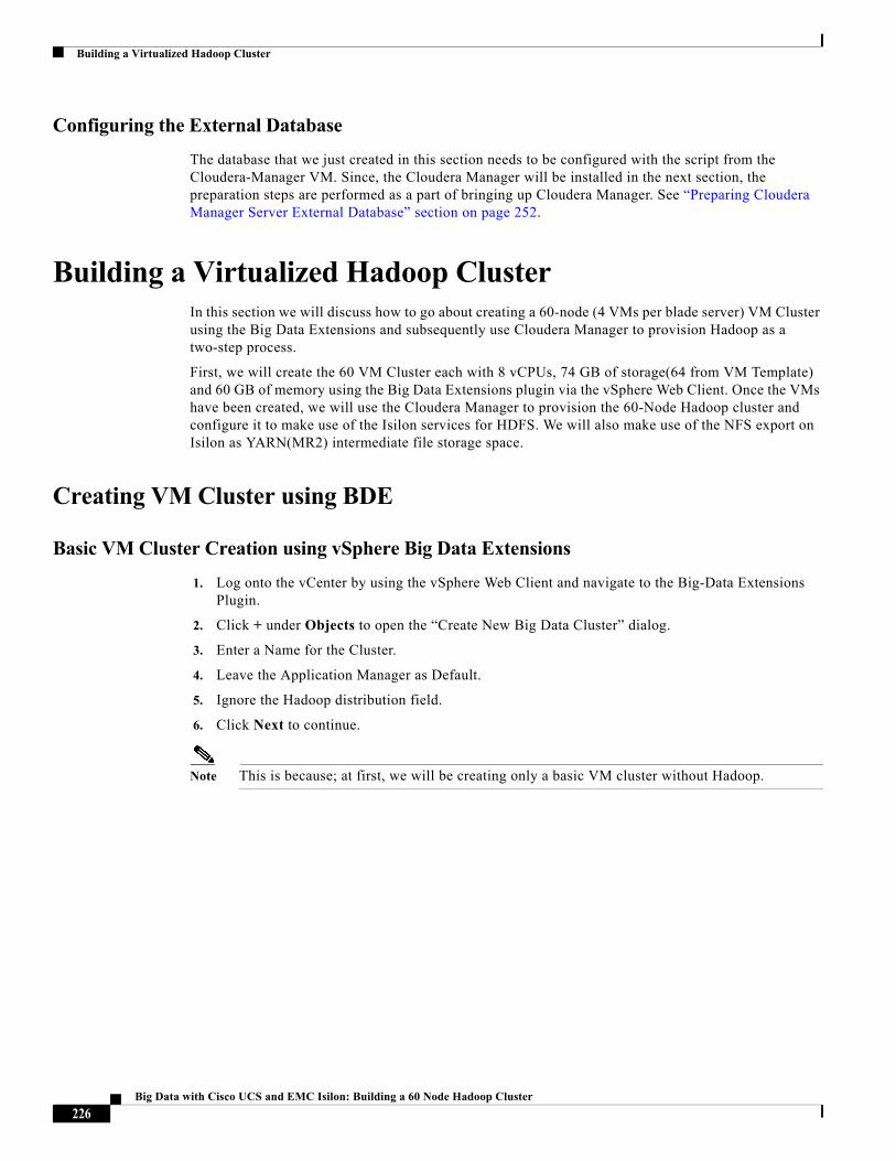
Building a Virtualized Hadoop Cluster
Configuring the External Database
The database that we just created in this section needs to be configured with the script from the Cloudera-Manager VM. Since, the Cloudera Manager will be installed in the next section, the preparation steps are performed as a part of bringing up Cloudera Manager. See “Preparing Cloudera Manager Server External Database” section on page 252.
Building a Virtualized Hadoop Cluster In this section we will discuss how to go about creating a 60-node (4 VMs per blade server) VM Cluster using the Big Data Extensions and subsequently use Cloudera Manager to provision Hadoop as a two-step process.
First, we will create the 60 VM Cluster each with 8 vCPUs, 74 GB of storage(64 from VM Template) and 60 GB of memory using the Big Data Extensions plugin via the vSphere Web Client. Once the VMs have been created, we will use the Cloudera Manager to provision the 60-Node Hadoop cluster and configure it to make use of the Isilon services for HDFS. We will also make use of the NFS export on Isilon as YARN(MR2) intermediate file storage space.
Creating VM Cluster using BDE
Basic VM Cluster Creation using vSphere Big Data Extensions
1. Log onto the vCenter by using the vSphere Web Client and navigate to the Big-Data Extensions Plugin.
2. Click + under Objects to open the “Create New Big Data Cluster” dialog.
3. Enter a Name for the Cluster.
4. Leave the Application Manager as Default.
5. Ignore the Hadoop distribution field.
6. Click Next to continue.
Note This is because; at first, we will be creating only a basic VM cluster without Hadoop.
226Big Data with Cisco UCS and EMC Isilon: Building a 60 Node Hadoop Cluster
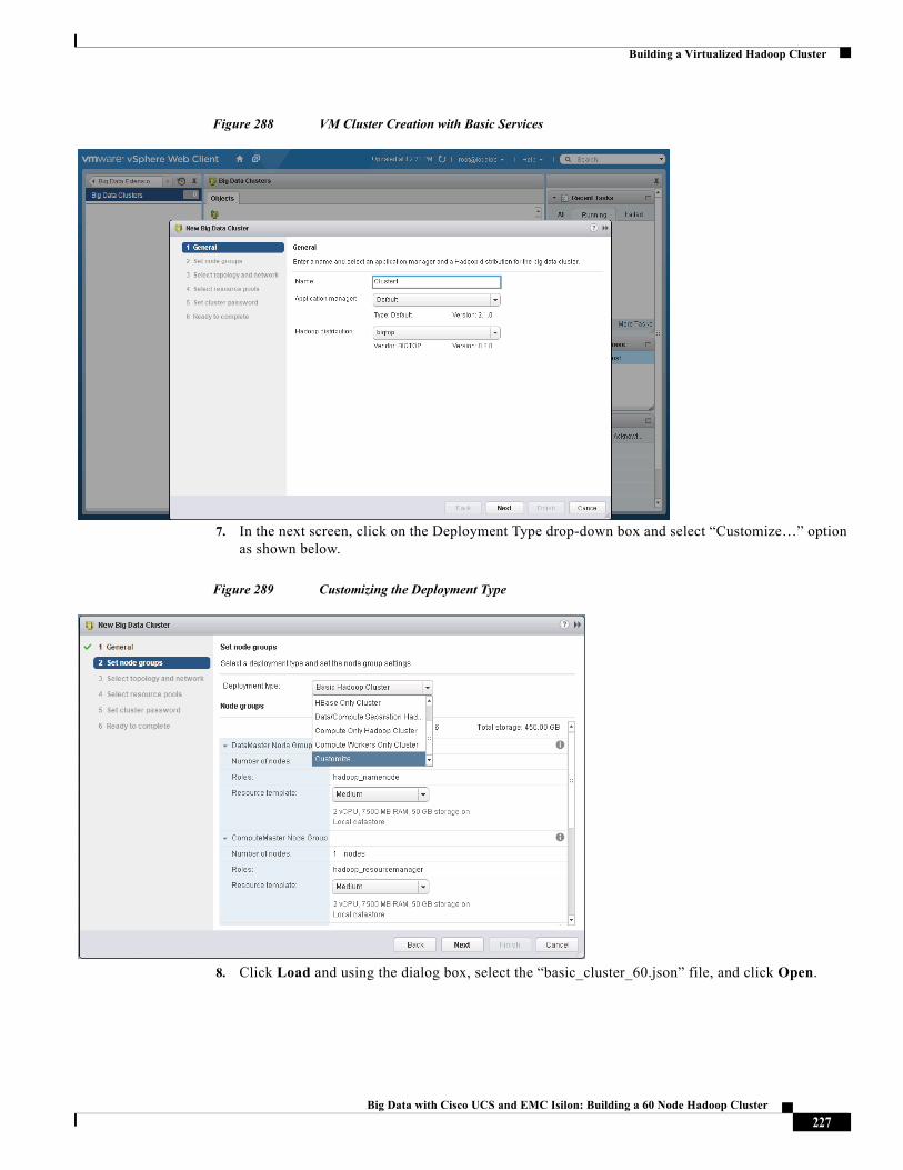
Building a Virtualized Hadoop Cluster
Figure 288 VM Cluster Creation with Basic Services
7. In the next screen, click on the Deployment Type drop-down box and select “Customize…” option as shown below.
Figure 289 Customizing the Deployment Type
8. Click Load and using the dialog box, select the “basic_cluster_60.json” file, and click Open.
227Big Data with Cisco UCS and EMC Isilon: Building a 60 Node Hadoop Cluster
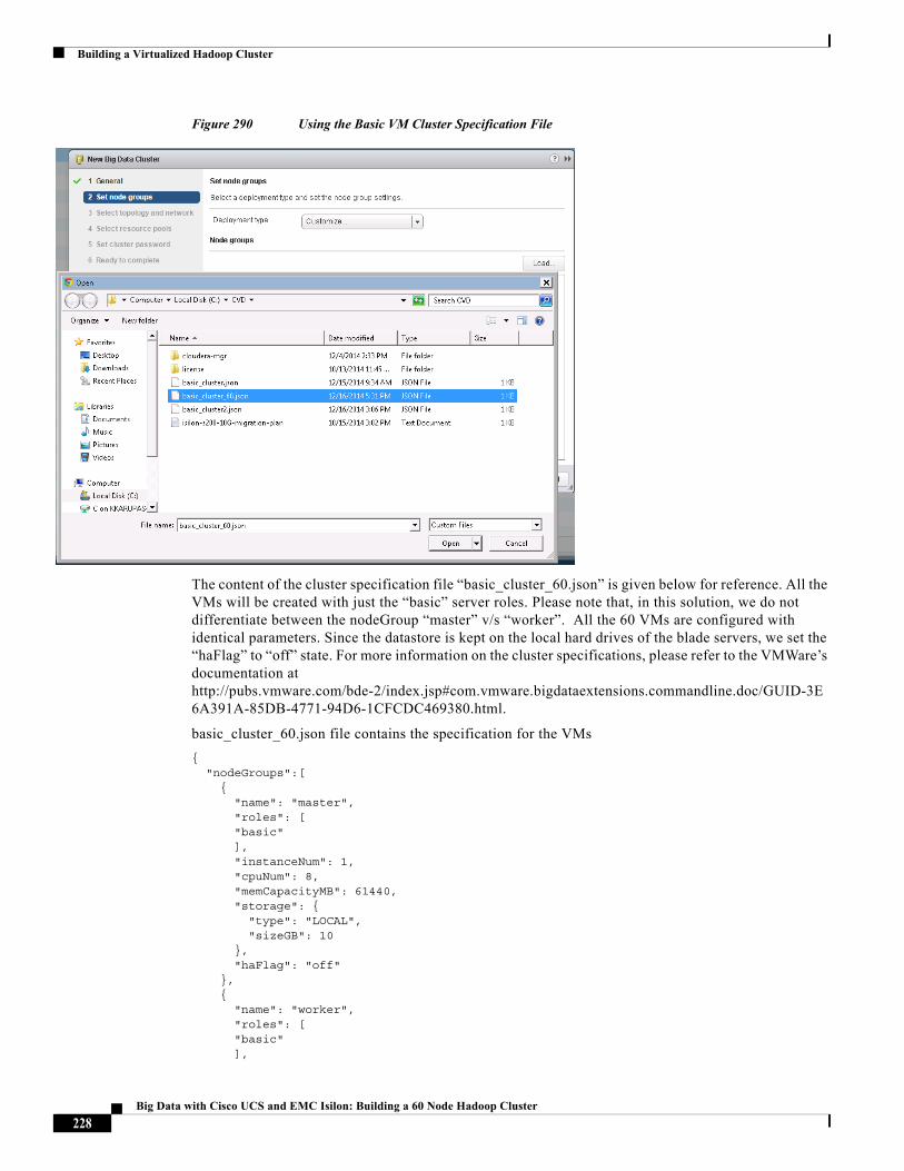
Building a Virtualized Hadoop Cluster
Figure 290 Using the Basic VM Cluster Specification File
The content of the cluster specification file “basic_cluster_60.json” is given below for reference. All the VMs will be created with just the “basic” server roles. Please note that, in this solution, we do not differentiate between the nodeGroup “master” v/s “worker”. All the 60 VMs are configured with identical parameters. Since the datastore is kept on the local hard drives of the blade servers, we set the “haFlag” to “off” state. For more information on the cluster specifications, please refer to the VMWare’s documentation at http://pubs.vmware.com/bde-2/index.jsp#com.vmware.bigdataextensions.commandline.doc/GUID-3E6A391A-85DB-4771-94D6-1CFCDC469380.html.
basic_cluster_60.json file contains the specification for the VMs
{ "nodeGroups":[ { "name": "master", "roles": [ "basic" ], "instanceNum": 1, "cpuNum": 8, "memCapacityMB": 61440, "storage": { "type": "LOCAL", "sizeGB": 10 }, "haFlag": "off" }, { "name": "worker", "roles": [ "basic" ],
228Big Data with Cisco UCS and EMC Isilon: Building a 60 Node Hadoop Cluster
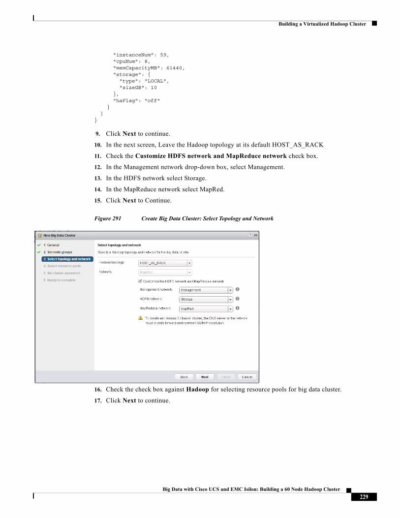
Building a Virtualized Hadoop Cluster
"instanceNum": 59, "cpuNum": 8, "memCapacityMB": 61440, "storage": { "type": "LOCAL", "sizeGB": 10 }, "haFlag": "off" } ]}
9. Click Next to continue.
10. In the next screen, Leave the Hadoop topology at its default HOST_AS_RACK
11. Check the Customize HDFS network and MapReduce network check box.
12. In the Management network drop-down box, select Management.
13. In the HDFS network select Storage.
14. In the MapReduce network select MapRed.
15. Click Next to Continue.
Figure 291 Create Big Data Cluster: Select Topology and Network
16. Check the check box against Hadoop for selecting resource pools for big data cluster.
17. Click Next to continue.
229Big Data with Cisco UCS and EMC Isilon: Building a 60 Node Hadoop Cluster
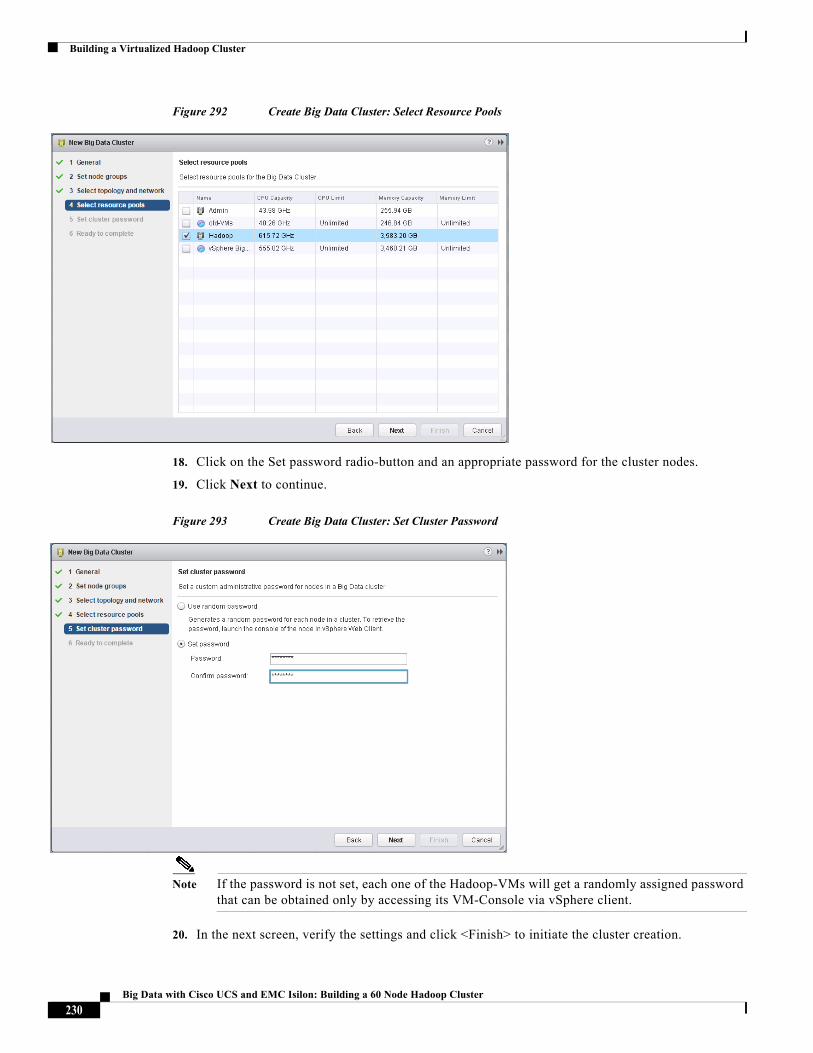
Building a Virtualized Hadoop Cluster
Figure 292 Create Big Data Cluster: Select Resource Pools
18. Click on the Set password radio-button and an appropriate password for the cluster nodes.
19. Click Next to continue.
Figure 293 Create Big Data Cluster: Set Cluster Password
Note If the password is not set, each one of the Hadoop-VMs will get a randomly assigned password that can be obtained only by accessing its VM-Console via vSphere client.
20. In the next screen, verify the settings and click <Finish> to initiate the cluster creation.
230Big Data with Cisco UCS and EMC Isilon: Building a 60 Node Hadoop Cluster
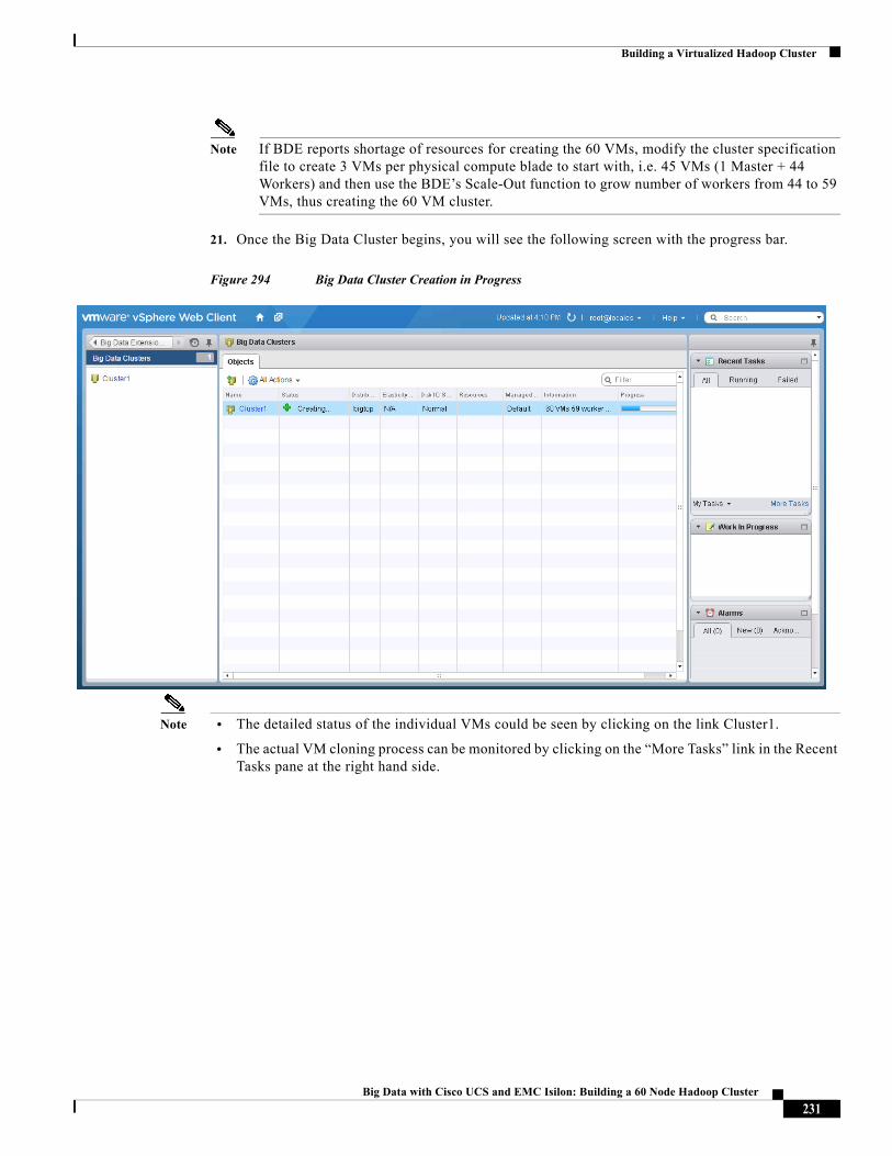
Building a Virtualized Hadoop Cluster
Note If BDE reports shortage of resources for creating the 60 VMs, modify the cluster specification file to create 3 VMs per physical compute blade to start with, i.e. 45 VMs (1 Master + 44 Workers) and then use the BDE’s Scale-Out function to grow number of workers from 44 to 59 VMs, thus creating the 60 VM cluster.
21. Once the Big Data Cluster begins, you will see the following screen with the progress bar.
Figure 294 Big Data Cluster Creation in Progress
Note • The detailed status of the individual VMs could be seen by clicking on the link Cluster1.
• The actual VM cloning process can be monitored by clicking on the “More Tasks” link in the Recent Tasks pane at the right hand side.
231Big Data with Cisco UCS and EMC Isilon: Building a 60 Node Hadoop Cluster
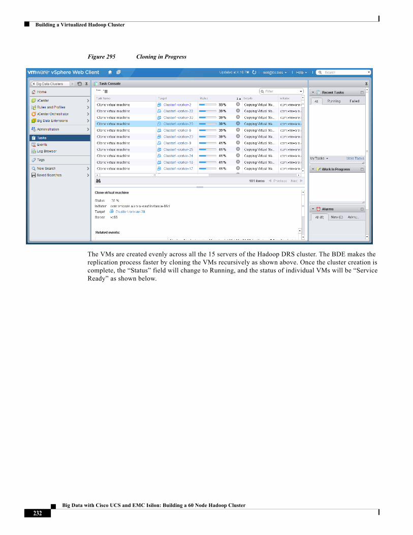
Building a Virtualized Hadoop Cluster
Figure 295 Cloning in Progress
The VMs are created evenly across all the 15 servers of the Hadoop DRS cluster. The BDE makes the replication process faster by cloning the VMs recursively as shown above. Once the cluster creation is complete, the “Status” field will change to Running, and the status of individual VMs will be “Service Ready” as shown below.
232Big Data with Cisco UCS and EMC Isilon: Building a 60 Node Hadoop Cluster
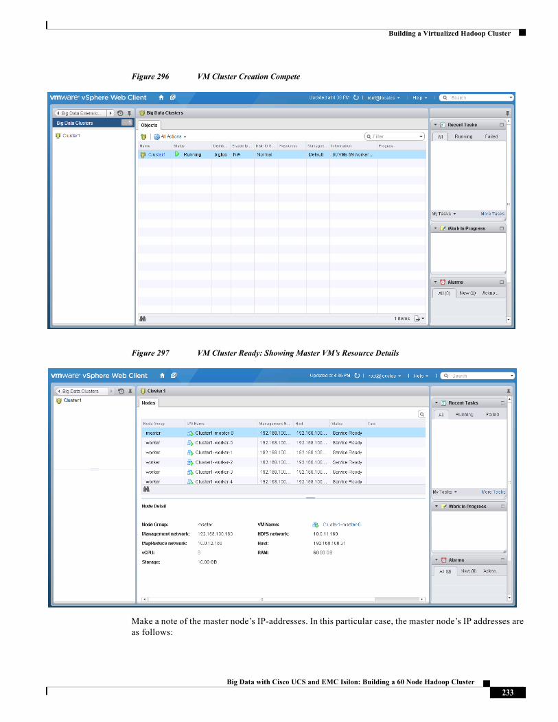
Building a Virtualized Hadoop Cluster
Figure 296 VM Cluster Creation Compete
Figure 297 VM Cluster Ready: Showing Master VM’s Resource Details
Make a note of the master node’s IP-addresses. In this particular case, the master node’s IP addresses are as follows:
233Big Data with Cisco UCS and EMC Isilon: Building a 60 Node Hadoop Cluster
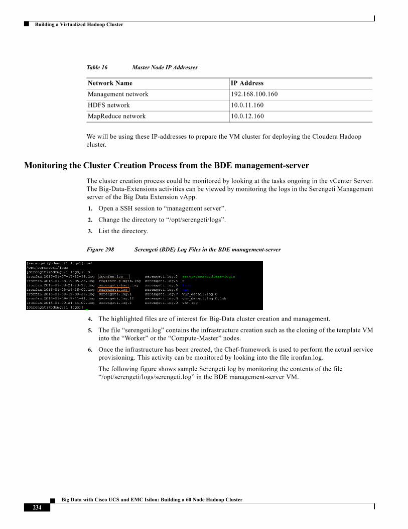
Building a Virtualized Hadoop Cluster
We will be using these IP-addresses to prepare the VM cluster for deploying the Cloudera Hadoop cluster.
Monitoring the Cluster Creation Process from the BDE management-server
The cluster creation process could be monitored by looking at the tasks ongoing in the vCenter Server. The Big-Data-Extensions activities can be viewed by monitoring the logs in the Serengeti Management server of the Big Data Extension vApp.
1. Open a SSH session to “management server”.
2. Change the directory to “/opt/serengeti/logs”.
3. List the directory.
Figure 298 Serengeti (BDE) Log Files in the BDE management-server
4. The highlighted files are of interest for Big-Data cluster creation and management.
5. The file “serengeti.log” contains the infrastructure creation such as the cloning of the template VM into the “Worker” or the “Compute-Master” nodes.
6. Once the infrastructure has been created, the Chef-framework is used to perform the actual service provisioning. This activity can be monitored by looking into the file ironfan.log.
The following figure shows sample Serengeti log by monitoring the contents of the file “/opt/serengeti/logs/serengeti.log” in the BDE management-server VM.
Table 16 Master Node IP Addresses
Network Name IP Address
Management network 192.168.100.160
HDFS network 10.0.11.160
MapReduce network 10.0.12.160
234Big Data with Cisco UCS and EMC Isilon: Building a 60 Node Hadoop Cluster
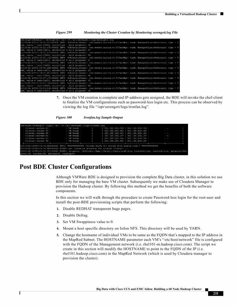
Building a Virtualized Hadoop Cluster
Figure 299 Monitoring the Cluster Creation by Monitoring serengeti.log File
7. Once the VM creation is complete and IP-address gets assigned, the BDE will invoke the chef-client to finalize the VM configurations such as password-less login etc. This process can be observed by viewing the log file “/opt/serengeti/logs/ironfan.log”.
Figure 300 Ironfan.log Sample Output
Post BDE Cluster Configurations
Although VMWare BDE is designed to provision the complete Big Data cluster, in this solution we use BDE only for managing the bare VM cluster. Subsequently we make use of Cloudera Manager to provision the Hadoop cluster. By following this method we get the benefits of both the software components.
In this section we will walk through the procedure to create Password-less login for the root-user and install the post-BDE provisioning scripts that perform the following:
1. Disable REDHAT transparent huge pages.
2. Disable Defrag.
3. Set VM Swappiness value to 0.
4. Mount a host specific directory on Isilon NFS. This directory will be used by YARN.
5. Change the hostname of individual VMs to be same as the FQDN that’s mapped to the IP address in the MapRed Subnet. The HOSTNAME parameter each VM’s “/etc/host/network” file is configured with the FQDN of the Management network (i.e. rhel101-m.hadoop.cisco.com). The script we create in this section will modify the HOSTNAME to point to the FQDN of the IP (i.e. rhel101.hadoop.cisco.com) in the MapRed Network (which is used by Cloudera manager to provision the cluster).
235Big Data with Cisco UCS and EMC Isilon: Building a 60 Node Hadoop Cluster
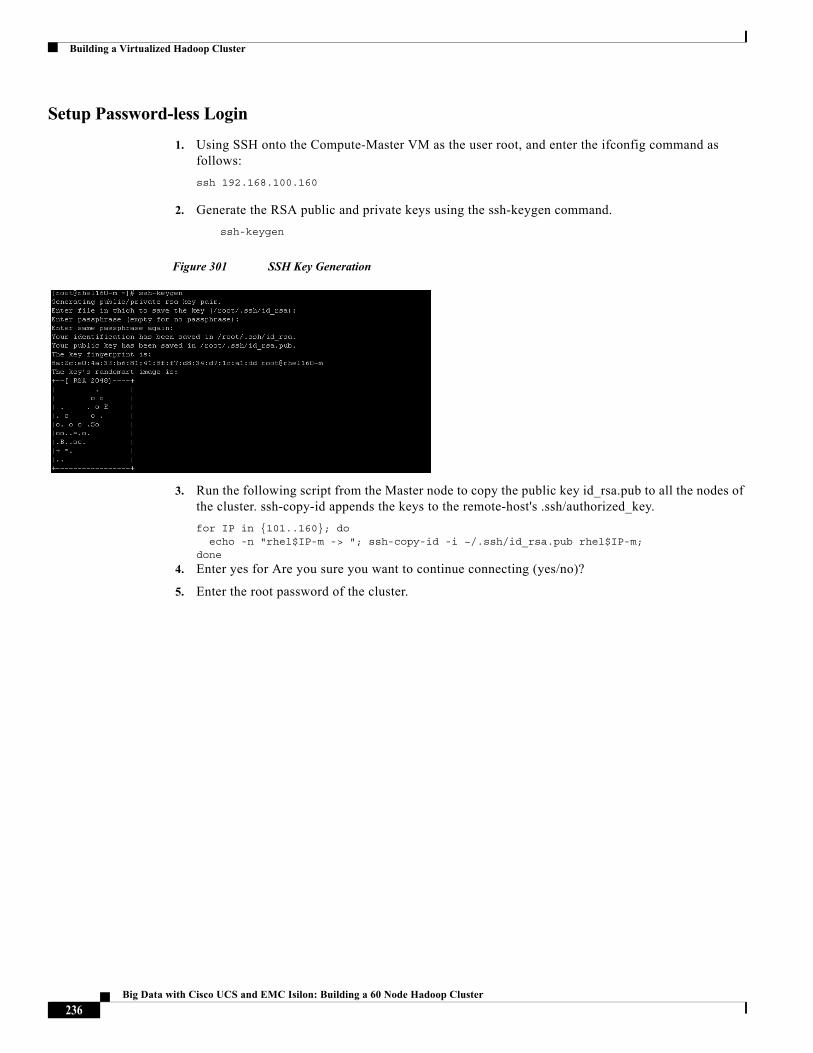
Building a Virtualized Hadoop Cluster
Setup Password-less Login
1. Using SSH onto the Compute-Master VM as the user root, and enter the ifconfig command as follows:
ssh 192.168.100.160
2. Generate the RSA public and private keys using the ssh-keygen command.
ssh-keygen
Figure 301 SSH Key Generation
3. Run the following script from the Master node to copy the public key id_rsa.pub to all the nodes of the cluster. ssh-copy-id appends the keys to the remote-host's .ssh/authorized_key.
for IP in {101..160}; do echo -n "rhel$IP-m -> "; ssh-copy-id -i ~/.ssh/id_rsa.pub rhel$IP-m;done
4. Enter yes for Are you sure you want to continue connecting (yes/no)?
5. Enter the root password of the cluster.
236Big Data with Cisco UCS and EMC Isilon: Building a 60 Node Hadoop Cluster
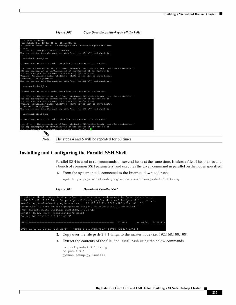
Building a Virtualized Hadoop Cluster
Figure 302 Copy Over the public-key to all the VMs
Note The steps 4 and 5 will be repeated for 60 times.
Installing and Configuring the Parallel SSH Shell
Parallel SSH is used to run commands on several hosts at the same time. It takes a file of hostnames and a bunch of common SSH parameters, and executes the given command in parallel on the nodes specified.
1. From the system that is connected to the Internet, download pssh.
wget https://parallel-ssh.googlecode.com/files/pssh-2.3.1.tar.gz
Figure 303 Download Parallel SSH
2. Copy over the file pssh-2.3.1.tar.gz to the master node (i.e. 192.168.100.108).
3. Extract the contents of the file, and install pssh using the below commands.
tar zxf pssh-2.3.1.tar.gzcd pss-2.3.1python setup.py install
237Big Data with Cisco UCS and EMC Isilon: Building a 60 Node Hadoop Cluster
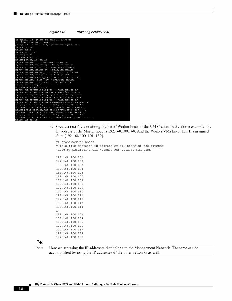
Building a Virtualized Hadoop Cluster
Figure 304 Installing Parallel SSH
4. Create a text file containing the list of Worker hosts of the VM Cluster. In the above example, the IP address of the Master node is 192.168.100.160. And the Worker VMs have their IPs assigned from [192.168.100–101–159].
vi /root/worker-nodes# This file contains ip address of all nodes of the cluster #used by parallel-shell (pssh). For Details man pssh
192.168.100.101192.168.100.102192.168.100.103192.168.100.104192.168.100.105192.168.100.106192.168.100.107192.168.100.108192.168.100.109192.168.100.110192.168.100.111192.168.100.112192.168.100.113192.168.100.114…192.168.100.153192.168.100.154192.168.100.155192.168.100.156192.168.100.157192.168.100.158192.168.100.159
Note Here we are using the IP addresses that belong to the Management Network. The same can be accomplished by using the IP addresses of the other networks as well.
238Big Data with Cisco UCS and EMC Isilon: Building a 60 Node Hadoop Cluster
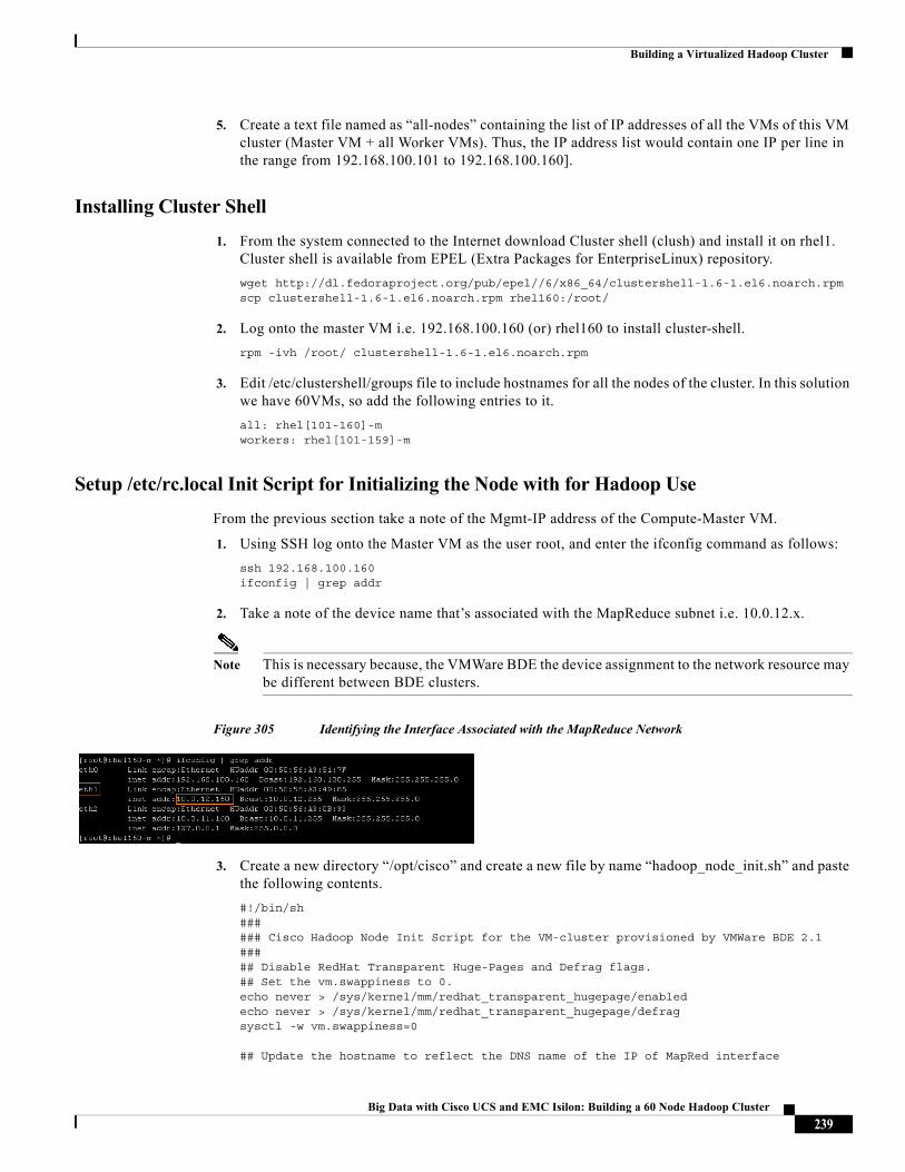
Building a Virtualized Hadoop Cluster
5. Create a text file named as “all-nodes” containing the list of IP addresses of all the VMs of this VM cluster (Master VM + all Worker VMs). Thus, the IP address list would contain one IP per line in the range from 192.168.100.101 to 192.168.100.160].
Installing Cluster Shell
1. From the system connected to the Internet download Cluster shell (clush) and install it on rhel1. Cluster shell is available from EPEL (Extra Packages for EnterpriseLinux) repository.
wget http://dl.fedoraproject.org/pub/epel//6/x86_64/clustershell-1.6-1.el6.noarch.rpmscp clustershell-1.6-1.el6.noarch.rpm rhel160:/root/
2. Log onto the master VM i.e. 192.168.100.160 (or) rhel160 to install cluster-shell.
rpm -ivh /root/ clustershell-1.6-1.el6.noarch.rpm
3. Edit /etc/clustershell/groups file to include hostnames for all the nodes of the cluster. In this solution we have 60VMs, so add the following entries to it.
all: rhel[101-160]-mworkers: rhel[101-159]-m
Setup /etc/rc.local Init Script for Initializing the Node with for Hadoop Use
From the previous section take a note of the Mgmt-IP address of the Compute-Master VM.
1. Using SSH log onto the Master VM as the user root, and enter the ifconfig command as follows:
ssh 192.168.100.160ifconfig | grep addr
2. Take a note of the device name that’s associated with the MapReduce subnet i.e. 10.0.12.x.
Note This is necessary because, the VMWare BDE the device assignment to the network resource may be different between BDE clusters.
Figure 305 Identifying the Interface Associated with the MapReduce Network
3. Create a new directory “/opt/cisco” and create a new file by name “hadoop_node_init.sh” and paste the following contents.
#!/bin/sh###### Cisco Hadoop Node Init Script for the VM-cluster provisioned by VMWare BDE 2.1##### Disable RedHat Transparent Huge-Pages and Defrag flags.## Set the vm.swappiness to 0.echo never > /sys/kernel/mm/redhat_transparent_hugepage/enabledecho never > /sys/kernel/mm/redhat_transparent_hugepage/defragsysctl -w vm.swappiness=0
## Update the hostname to reflect the DNS name of the IP of MapRed interface
239Big Data with Cisco UCS and EMC Isilon: Building a 60 Node Hadoop Cluster
Building a Virtualized Hadoop Cluster
## This part of the script is copied from VMWare Big Data Extensions 2.1## Administrator's and User's Guide - Page 125#### Please make sure that the NIC device name "eth1" below is the one ## that's associated with the MapReduce Network. If not, change that ## parameter appropriately to eth0 or eth2.sleep 30ETHIP=`/sbin/ifconfig eth1 | grep "inet addr" | awk '{print $2}' | sed 's/addr://'`FQDN=$ETHIPRET=`/bin/ipcalc --silent --hostname $ETHIP`if [ "$?" = "0" ]; thenFQDN=`echo $RET | awk -F= '{print $2}'`fiecho "set hostname to ${FQDN}"`hostname ${FQDN}`sed -i s/^HOSTNAME=.*/HOSTNAME="$FQDN"/ /etc/sysconfig/network
## Fix the MTU## When the BDE used with Static-IPs, it sets MTU value to be 1500 by default.## In this solution the NICs are capable of Jumbo MTUs.##ip link set dev eth0 mtu 9000ip link set dev eth1 mtu 9000ip link set dev eth2 mtu 9000
## Mount the Isilon NFS directorymount -aISILON_NFS=/mnt/isilon_nfsrm -f /DATA/nfs1mkdir -p $ISILON_NFS/hadoop-local-data/$FQDNchmod 777 $ISILON_NFS/hadoop-local-data/$FQDNmkdir –p /DATAln -s -f $ISILON_NFS/hadoop-local-data/$FQDN /DATA/nfs1
240Big Data with Cisco UCS and EMC Isilon: Building a 60 Node Hadoop Cluster
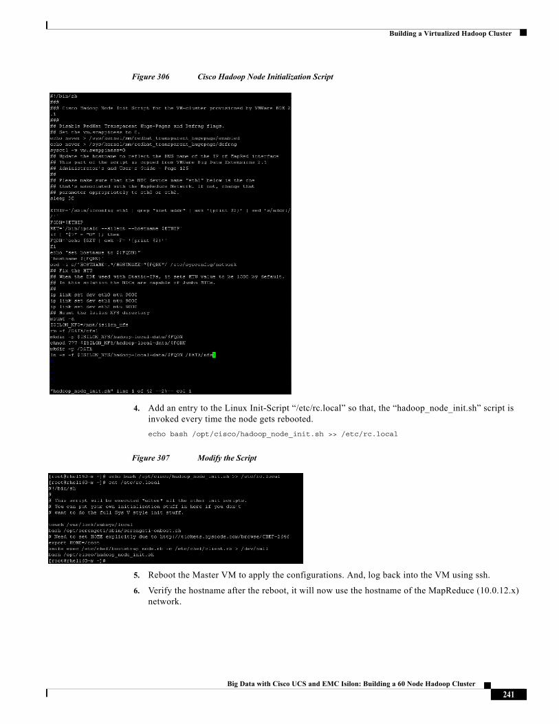
Building a Virtualized Hadoop Cluster
Figure 306 Cisco Hadoop Node Initialization Script
4. Add an entry to the Linux Init-Script “/etc/rc.local” so that, the “hadoop_node_init.sh” script is invoked every time the node gets rebooted.
echo bash /opt/cisco/hadoop_node_init.sh >> /etc/rc.local
Figure 307 Modify the Script
5. Reboot the Master VM to apply the configurations. And, log back into the VM using ssh.
6. Verify the hostname after the reboot, it will now use the hostname of the MapReduce (10.0.12.x) network.
241Big Data with Cisco UCS and EMC Isilon: Building a 60 Node Hadoop Cluster
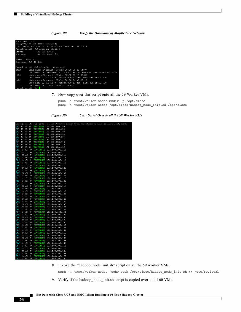
Building a Virtualized Hadoop Cluster
Figure 308 Verify the Hostname of MapReduce Network
7. Now copy over this script onto all the 59 Worker VMs.
pssh –h /root/worker-nodes mkdir –p /opt/ciscopscp –h /root/worker-nodes /opt/cisco/hadoop_node_init.sh /opt/cisco
Figure 309 Copy Script Over to all the 59 Worker VMs
8. Invoke the “hadoop_node_init.sh” script on all the 59 worker VMs.
pssh –h /root/worker-nodes “echo bash /opt/cisco/hadoop_node_init.sh >> /etc/rc.local
9. Verify if the hadoop_node_init.sh script is copied over to all 60 VMs.
242Big Data with Cisco UCS and EMC Isilon: Building a 60 Node Hadoop Cluster
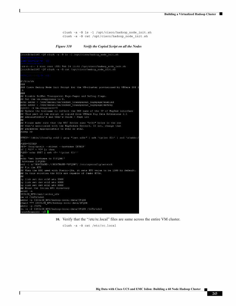
Building a Virtualized Hadoop Cluster
clush -a -B ls -l /opt/cisco/hadoop_node_init.shclush -a -B cat /opt/cisco/hadoop_node_init.sh
Figure 310 Verify the Copied Script on all the Nodes
10. Verify that the “/etc/rc.local” files are same across the entire VM cluster.
clush -a -B cat /etc/rc.local
243Big Data with Cisco UCS and EMC Isilon: Building a 60 Node Hadoop Cluster
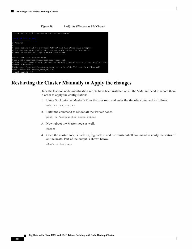
Building a Virtualized Hadoop Cluster
Figure 311 Verify the Files Across VM Cluster
Restarting the Cluster Manually to Apply the changes
Once the Hadoop node initialization scripts have been installed on all the VMs, we need to reboot them in order to apply the configurations.
1. Using SSH onto the Master VM as the user root, and enter the ifconfig command as follows:
ssh 192.168.100.160
2. Enter the command to reboot all the worker nodes.
pssh –h /root/worker-nodes reboot
3. Now reboot the Master node as well.
reboot
4. Once the master node is back up, log back in and use cluster-shell command to verify the status of all the hosts. Part of the output is shown below.
clush –a hostname
244Big Data with Cisco UCS and EMC Isilon: Building a 60 Node Hadoop Cluster
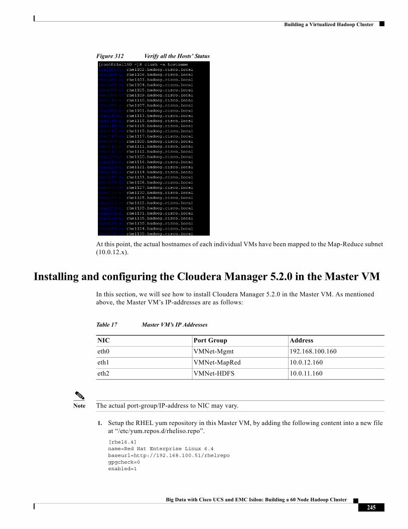
Building a Virtualized Hadoop Cluster
Figure 312 Verify all the Hosts’ Status
At this point, the actual hostnames of each individual VMs have been mapped to the Map-Reduce subnet (10.0.12.x).
Installing and configuring the Cloudera Manager 5.2.0 in the Master VM
In this section, we will see how to install Cloudera Manager 5.2.0 in the Master VM. As mentioned above, the Master VM’s IP-addresses are as follows:
Note The actual port-group/IP-address to NIC may vary.
1. Setup the RHEL yum repository in this Master VM, by adding the following content into a new file at “/etc/yum.repos.d/rheliso.repo”.
[rhel6.4]name=Red Hat Enterprise Linux 6.4baseurl=http://192.168.100.51/rhelrepogpgcheck=0enabled=1
Table 17 Master VM’s IP Addresses
NIC Port Group Address
eth0 VMNet-Mgmt 192.168.100.160
eth1 VMNet-MapRed 10.0.12.160
eth2 VMNet-HDFS 10.0.11.160
245Big Data with Cisco UCS and EMC Isilon: Building a 60 Node Hadoop Cluster
Building a Virtualized Hadoop Cluster
Figure 313 Cloudera-Manager VM: Create RHEL YUM Repository File
Note Since this VM is created from our custom RHEL-Template VM, the RHEL yum-repo should be already present under “/etc/yum.repos.d”.
2. Setup the Cloudera Manager yum repository, by adding the following content into a new file at “/etc/yum.repos.d/cloudera-manager.repo”.
[cloudera-manager]# Packages for Cloudera Manager, Version 5, on RedHat 6 x86_64name=Cloudera Managerbaseurl=http://192.168.100.51/cm/5/enabled=1gpgcheck=0
Figure 314 Cloudera-Manager VM: Create the Cloudera-Manager YUM Repository File
3. Download the Cloudera Manager installer binary file from the Admin-VM by using the command:
wget http://192.168.100.51/cm/installer/cloudera-manager-installer.bin
Figure 315 Downloading the Cloudera Manager Installer Binary File into the Cloudera-Manager VM
246Big Data with Cisco UCS and EMC Isilon: Building a 60 Node Hadoop Cluster
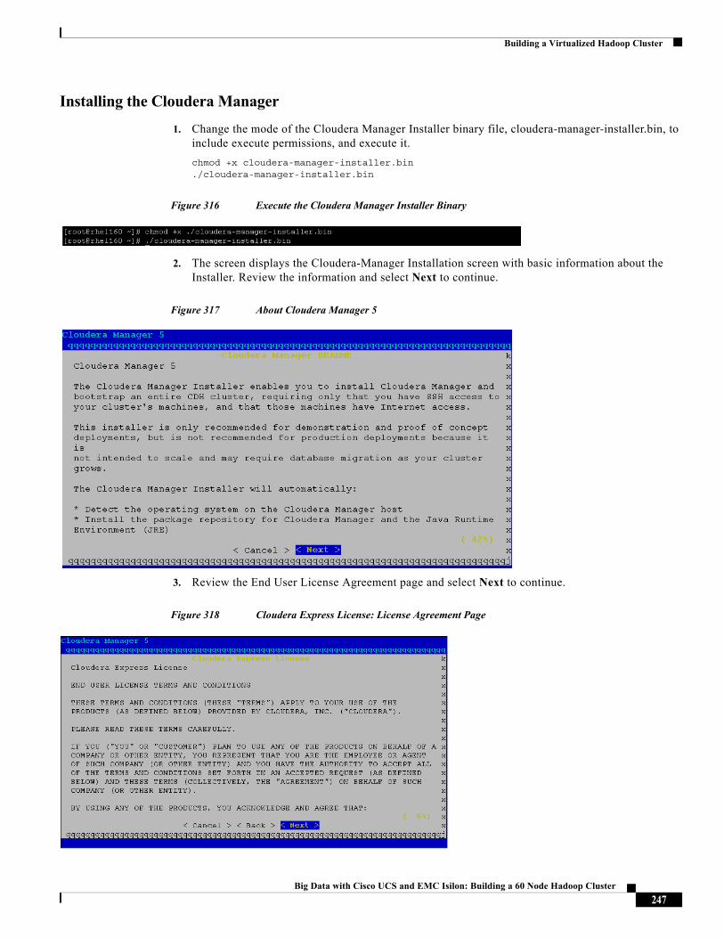
Building a Virtualized Hadoop Cluster
Installing the Cloudera Manager
1. Change the mode of the Cloudera Manager Installer binary file, cloudera-manager-installer.bin, to include execute permissions, and execute it.
chmod +x cloudera-manager-installer.bin./cloudera-manager-installer.bin
Figure 316 Execute the Cloudera Manager Installer Binary
2. The screen displays the Cloudera-Manager Installation screen with basic information about the Installer. Review the information and select Next to continue.
Figure 317 About Cloudera Manager 5
3. Review the End User License Agreement page and select Next to continue.
Figure 318 Cloudera Express License: License Agreement Page
247Big Data with Cisco UCS and EMC Isilon: Building a 60 Node Hadoop Cluster
Building a Virtualized Hadoop Cluster
4. Select Yes to continue; also accept the Oracle JDK installation agreement to continue onto Cloudera Manager Installation.
5. Once the Cloudera-Manager installation is complete, the installer prompts the following message with the URL to access the Cloudera-Manager.
Figure 319 URL for Logging into Cloudera Manager
6. Save the URL displayed i.e. http://192.168.100.160:7180. Use this URL to access the Cloudera Manager using your web browser. Press <OK> to complete the installation.
7. Now verify the Cloudera Manager is accessible via the web-browser by visiting the URL:http://192.168.100.160:7180.
8. Login as admin user with the default password “admin”.
248Big Data with Cisco UCS and EMC Isilon: Building a 60 Node Hadoop Cluster
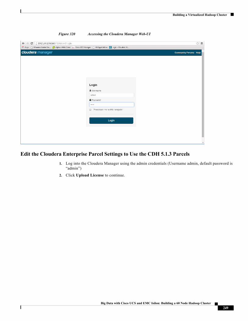
Building a Virtualized Hadoop Cluster
Figure 320 Accessing the Cloudera Manager Web-UI
Edit the Cloudera Enterprise Parcel Settings to Use the CDH 5.1.3 Parcels
1. Log into the Cloudera Manager using the admin credentials (Username admin, default password is “admin”)
2. Click Upload License to continue.
249Big Data with Cisco UCS and EMC Isilon: Building a 60 Node Hadoop Cluster
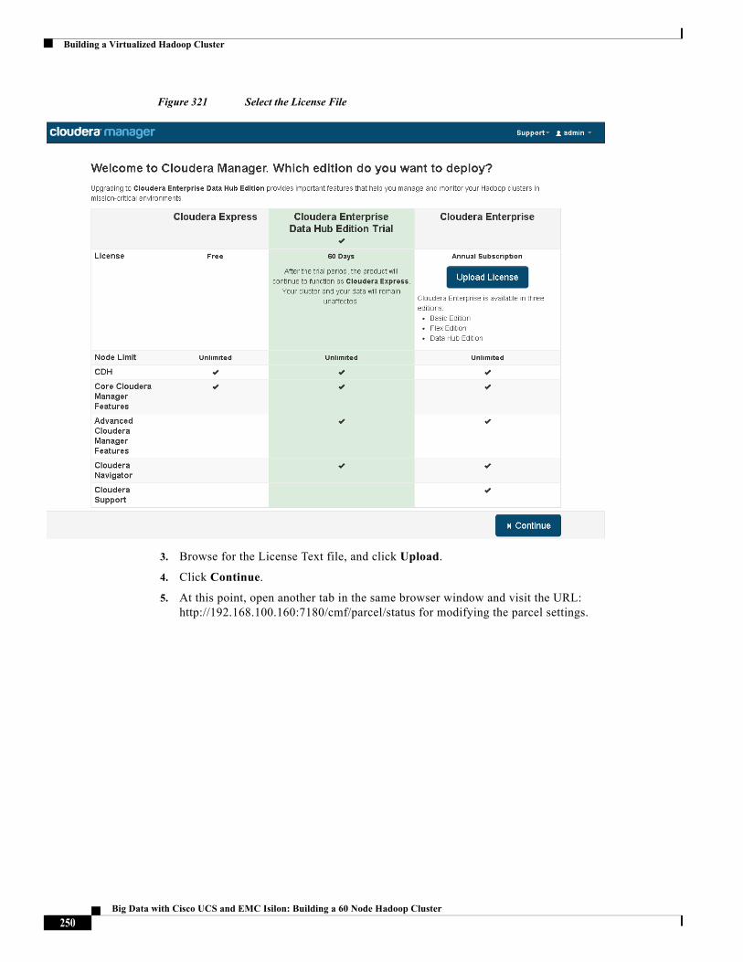
Building a Virtualized Hadoop Cluster
Figure 321 Select the License File
3. Browse for the License Text file, and click Upload.
4. Click Continue.
5. At this point, open another tab in the same browser window and visit the URL: http://192.168.100.160:7180/cmf/parcel/status for modifying the parcel settings.
250Big Data with Cisco UCS and EMC Isilon: Building a 60 Node Hadoop Cluster
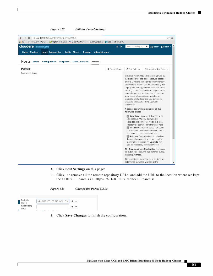
Building a Virtualized Hadoop Cluster
Figure 322 Edit the Parcel Settings
6. Click Edit Settings on this page:
7. Click - to remove all the remote repository URLs, and add the URL to the location where we kept the CDH 5.1.3 parcels i.e. http://192.168.100.51/cdh/5.1.3/parcels/
Figure 323 Change the Parcel URLs
8. Click Save Changes to finish the configuration.
251Big Data with Cisco UCS and EMC Isilon: Building a 60 Node Hadoop Cluster
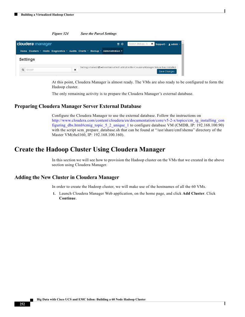
Building a Virtualized Hadoop Cluster
Figure 324 Save the Parcel Settings
At this point, Cloudera Manager is almost ready. The VMs are also ready to be configured to form the Hadoop cluster.
The only remaining activity is to prepare the Cloudera Manager’s external database.
Preparing Cloudera Manager Server External Database
Configure the Cloudera Manager to use the external database. Follow the instructions on http://www.cloudera.com/content/cloudera/en/documentation/core/v5-2-x/topics/cm_ig_installing_configuring_dbs.html#cmig_topic_5_2_unique_1 to configure database VM (CMDB, IP: 192.168.100.90) with the script scm_prepare_database.sh that can be found at “/usr/share/cmf/shema” directory of the Master VM(rhel160, IP: 192.168.100.160).
Create the Hadoop Cluster Using Cloudera Manager
In this section we will see how to provision the Hadoop cluster on the VMs that we created in the above section using Cloudera Manager.
Adding the New Cluster in Cloudera Manager
In order to create the Hadoop cluster, we will make use of the hostnames of all the 60 VMs.
1. Launch Cloudera Manager Web application, on the home page, and click Add Cluster. Click Continue.
252Big Data with Cisco UCS and EMC Isilon: Building a 60 Node Hadoop Cluster
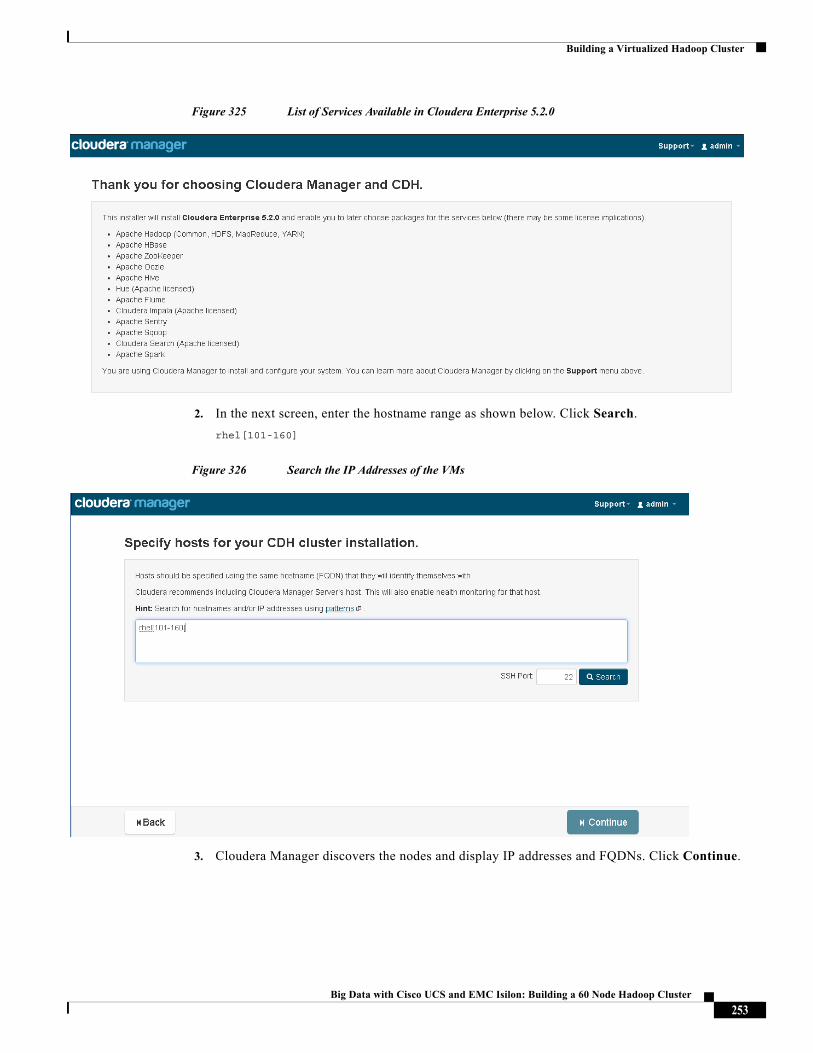
Building a Virtualized Hadoop Cluster
Figure 325 List of Services Available in Cloudera Enterprise 5.2.0
2. In the next screen, enter the hostname range as shown below. Click Search.
rhel[101-160]
Figure 326 Search the IP Addresses of the VMs
3. Cloudera Manager discovers the nodes and display IP addresses and FQDNs. Click Continue.
253Big Data with Cisco UCS and EMC Isilon: Building a 60 Node Hadoop Cluster
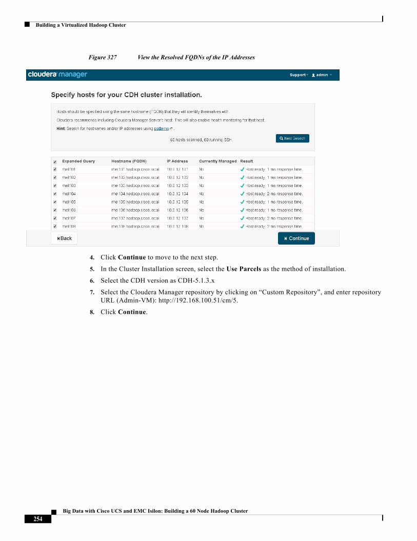
Building a Virtualized Hadoop Cluster
Figure 327 View the Resolved FQDNs of the IP Addresses
4. Click Continue to move to the next step.
5. In the Cluster Installation screen, select the Use Parcels as the method of installation.
6. Select the CDH version as CDH-5.1.3.x
7. Select the Cloudera Manager repository by clicking on “Custom Repository”, and enter repository URL (Admin-VM): http://192.168.100.51/cm/5.
8. Click Continue.
254Big Data with Cisco UCS and EMC Isilon: Building a 60 Node Hadoop Cluster
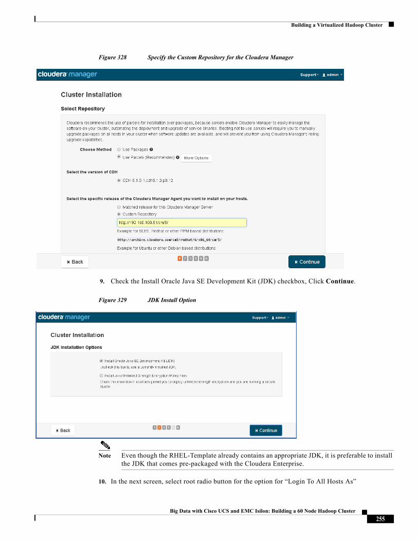
Building a Virtualized Hadoop Cluster
Figure 328 Specify the Custom Repository for the Cloudera Manager
9. Check the Install Oracle Java SE Development Kit (JDK) checkbox, Click Continue.
Figure 329 JDK Install Option
Note Even though the RHEL-Template already contains an appropriate JDK, it is preferable to install the JDK that comes pre-packaged with the Cloudera Enterprise.
10. In the next screen, select root radio button for the option for “Login To All Hosts As”
255Big Data with Cisco UCS and EMC Isilon: Building a 60 Node Hadoop Cluster
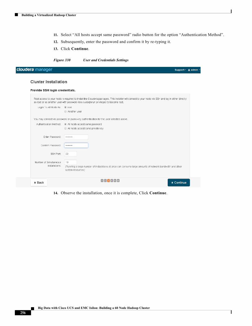
Building a Virtualized Hadoop Cluster
11. Select “All hosts accept same password” radio button for the option “Authentication Method”.
12. Subsequently, enter the password and confirm it by re-typing it.
13. Click Continue.
Figure 330 User and Credentials Settings
14. Observe the installation, once it is complete, Click Continue.
256Big Data with Cisco UCS and EMC Isilon: Building a 60 Node Hadoop Cluster
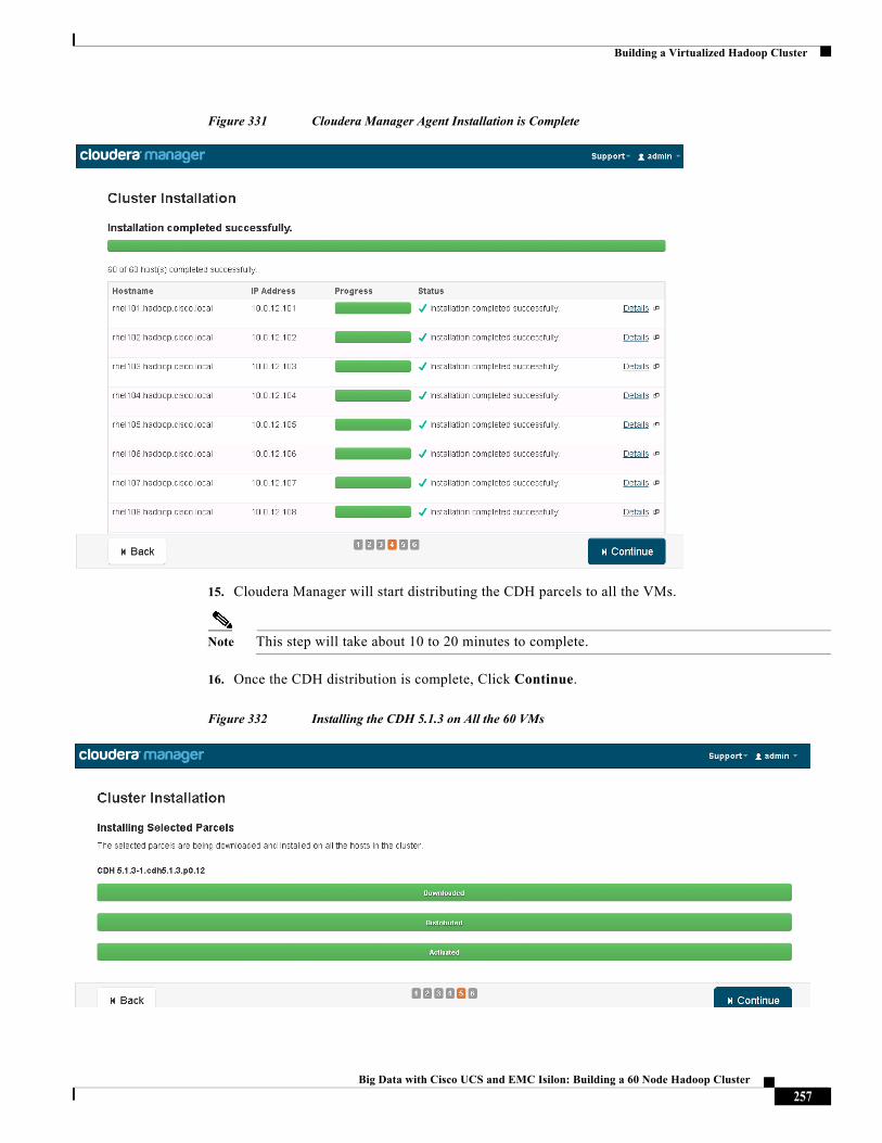
Building a Virtualized Hadoop Cluster
Figure 331 Cloudera Manager Agent Installation is Complete
15. Cloudera Manager will start distributing the CDH parcels to all the VMs.
Note This step will take about 10 to 20 minutes to complete.
16. Once the CDH distribution is complete, Click Continue.
Figure 332 Installing the CDH 5.1.3 on All the 60 VMs
257Big Data with Cisco UCS and EMC Isilon: Building a 60 Node Hadoop Cluster
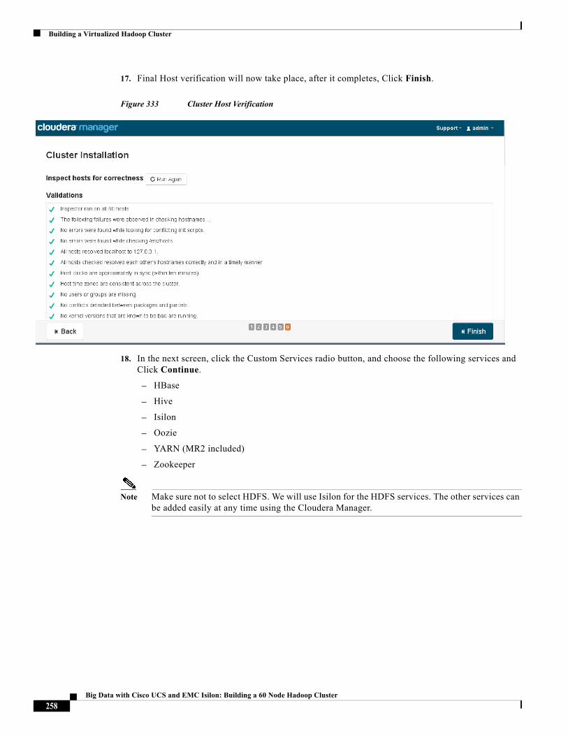
Building a Virtualized Hadoop Cluster
17. Final Host verification will now take place, after it completes, Click Finish.
Figure 333 Cluster Host Verification
18. In the next screen, click the Custom Services radio button, and choose the following services and Click Continue.
– HBase
– Hive
– Isilon
– Oozie
– YARN (MR2 included)
– Zookeeper
Note Make sure not to select HDFS. We will use Isilon for the HDFS services. The other services can be added easily at any time using the Cloudera Manager.
258Big Data with Cisco UCS and EMC Isilon: Building a 60 Node Hadoop Cluster
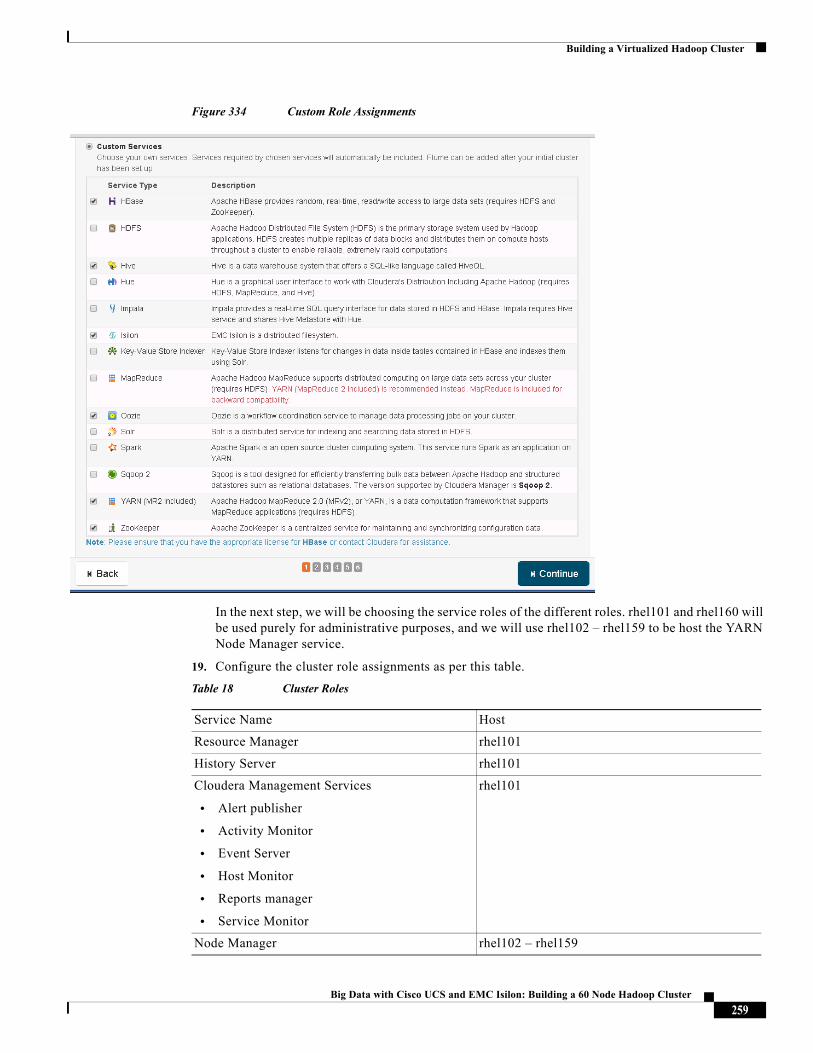
Building a Virtualized Hadoop Cluster
Figure 334 Custom Role Assignments
In the next step, we will be choosing the service roles of the different roles. rhel101 and rhel160 will be used purely for administrative purposes, and we will use rhel102 – rhel159 to be host the YARN Node Manager service.
19. Configure the cluster role assignments as per this table.
Table 18 Cluster Roles
Service Name Host
Resource Manager rhel101
History Server rhel101
Cloudera Management Services
• Alert publisher
• Activity Monitor
• Event Server
• Host Monitor
• Reports manager
• Service Monitor
rhel101
Node Manager rhel102 – rhel159
259Big Data with Cisco UCS and EMC Isilon: Building a 60 Node Hadoop Cluster
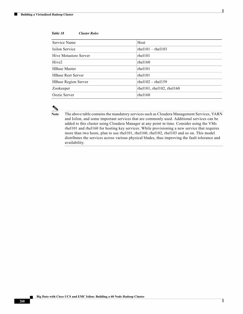
Building a Virtualized Hadoop Cluster
Note The above table contains the mandatory services such as Cloudera Management Services, YARN and Isilon, and some important services that are commonly used. Additional services can be added to this cluster using Cloudera Manager at any point in time. Consider using the VMs rhel101 and rhel160 for hosting key services. While provisioning a new service that requires more than two hosts, plan to use rhel101, rhel160, rhel102, rhel103 and so on. This model distributes the services across various physical blades, thus improving the fault tolerance and availability.
Isilon Service rhel101 – rhel103
Hive Metastore Server rhel101
Hive2 rhel160
HBase Master rhel101
HBase Rest Server rhel101
HBase Region Server rhel102 – rhel159
Zookeeper rhel101, rhel102, rhel160
Oozie Server rhel160
Table 18 Cluster Roles
Service Name Host
260Big Data with Cisco UCS and EMC Isilon: Building a 60 Node Hadoop Cluster
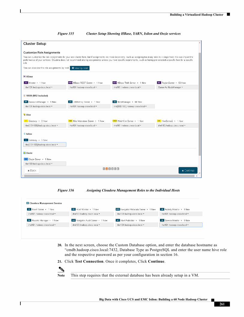
Building a Virtualized Hadoop Cluster
Figure 335 Cluster Setup Showing HBase, YARN, Isilon and Oozie services
Figure 336 Assigning Cloudera Management Roles to the Individual Hosts
20. In the next screen, choose the Custom Database option, and enter the database hostname as “cmdb.hadoop.cisco.local:7432, Database Type as PostgreSQL and enter the user name hive role and the respective password as per your configuration in section 16.
21. Click Test Connection. Once it completes, Click Continue.
Note This step requires that the external database has been already setup in a VM.
261Big Data with Cisco UCS and EMC Isilon: Building a 60 Node Hadoop Cluster
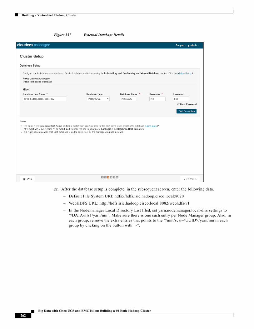
Building a Virtualized Hadoop Cluster
Figure 337 External Database Details
22. After the database setup is complete, in the subsequent screen, enter the following data.
– Default File System URI: hdfs://hdfs.isic.hadoop.cisco.local:8020
– WebHDFS URL: http://hdfs.isic.hadoop.cisco.local:8082/webhdfs/v1
– In the Nodemanager Local Directory List filed, set yarn.nodemanager.local-dirs settings to “/DATA/nfs1/yarn/nm”. Make sure there is one such entry per Node Manager group. Also, in each group, remove the extra entries that points to the “/mnt/scsi-<UUID>/yarn/nm in each group by clicking on the button with “-”.
262Big Data with Cisco UCS and EMC Isilon: Building a 60 Node Hadoop Cluster
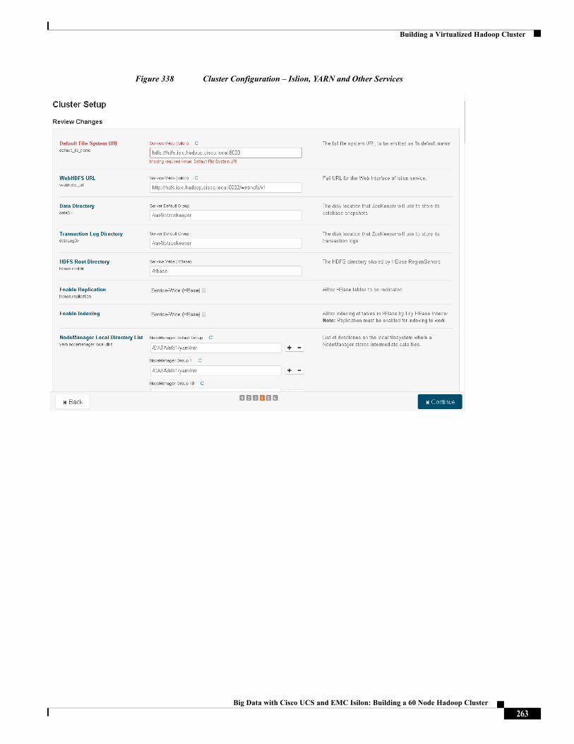
Building a Virtualized Hadoop Cluster
Figure 338 Cluster Configuration – Islion, YARN and Other Services
263Big Data with Cisco UCS and EMC Isilon: Building a 60 Node Hadoop Cluster
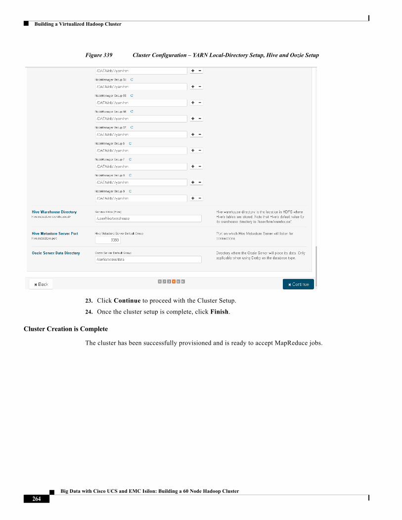
Building a Virtualized Hadoop Cluster
Figure 339 Cluster Configuration – YARN Local-Directory Setup, Hive and Oozie Setup
23. Click Continue to proceed with the Cluster Setup.
24. Once the cluster setup is complete, click Finish.
Cluster Creation is Complete
The cluster has been successfully provisioned and is ready to accept MapReduce jobs.
264Big Data with Cisco UCS and EMC Isilon: Building a 60 Node Hadoop Cluster
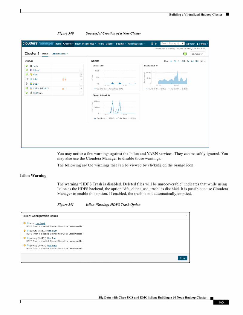
Building a Virtualized Hadoop Cluster
Figure 340 Successful Creation of a New Cluster
You may notice a few warnings against the Isilon and YARN services. They can be safely ignored. You may also use the Cloudera Manager to disable those warnings.
The following are the warnings that can be viewed by clicking on the orange icon.
Isilon Warning
The warning “HDFS Trash is disabled. Deleted files will be unrecoverable” indicates that while using Isilon as the HDFS backend, the option “dfs_client_use_trash” is disabled. It is possible to use Cloudera Manager to enable this option. If enabled, the trash is not automatically emptied.
Figure 341 Isilon Warning: HDFS Trash Option
265Big Data with Cisco UCS and EMC Isilon: Building a 60 Node Hadoop Cluster
Building a Virtualized Hadoop Cluster
YARN Configuration Warning
This warning indicates that the YARN setting “mapred_submit_replication” is not set to proper value and it indicates number of data nodes is 0. This warning must be simply ignored. Please do not make any changes suggested by the Cloudera Manager. Making any change to the variable may make your cluster unable to perform map-reduce jobs.
Figure 342 YARN Configuration Warning
This completes the basic configuration of the Hadoop cluster.
Configure the YARN(MR2) Service Settings
Using Cloudera Manager, configure the YARN (MR2 Included) service settings to the below recommended settings.
Table 19 YARN (MR2) Settings
Parameter Value Description
mapreduce.map.memory.mb 4096 Memory used by the YARN container for running a map task
mapreduce.map.java.opts -Xmx3328m Maximum memory allocated to the JVM performing the map task. This value should be less than that of the parameter: mapreduce.map.memory.mb.
mapreduce.map.memory.mb 6144 Memory used by the YARN container for running a reduce task.
mapreduce.map.java.opts -Xmx5376m Maximum memory allocated to the JVM performing the reduce task. This value should be less than that of the parameter: mapreduce.reduce.memory.mb.
mapreduce.task.io.sort.mb 1024 The total amount of buffer memory to use while sorting files, in megabytes.
mapreduce.task.timeout 900000 The number of milliseconds before a task will be terminated. Default value is 10min (600000 ms). This change is optional.
266Big Data with Cisco UCS and EMC Isilon: Building a 60 Node Hadoop Cluster
Building a Virtualized Hadoop Cluster
yarn.log-aggregation-enable true Whether to enable log aggregation. Log aggregation collects each container's logs and moves these logs onto a file-system, for e.g. HDFS, after the application completes. Users can configure the "yarn.nodemanager.remote-app-log-dir" and "yarn.nodemanager.remote-app-log-dir-suffix" properties to determine where these logs are moved to. Users can access the logs via the Application Timeline Server.
yarn.scheduler.minimum-allocation-mb
4096 The minimum allocation for every container request at the RM, in MBs. Memory requests lower than this won't take effect, and the specified value will get allocated at minimum.
yarn.scheduler.maximum-allocation-mb
53248 The maximum allocation for every container request at the RM, in MBs. Memory requests higher than this won't take effect, and will get capped to this value.
yarn.nodemanager.resource.memory-mb
53248 Amount of physical memory, in MB, that can be allocated for containers. This parameter determines the number of containers created per VM.
yarn.nodemanager.local-dirs /DATA/nfs1 Node manager intermediate directory space on Isilon NFS.
yarn.nodemanager.resource.cpu-vcores
8 Number of CPU cores that can be allocated for containers.
yarn.scheduler.maximum-allocation-vcores
8 The maximum allocation for every container request at the RM, in terms of virtual CPU cores. Requests higher than this won't take effect, and will get capped to this value.
yarn.app.mapreduce.am.resource.cpu-vcores
1 The number of virtual CPU cores the MR AppMaster needs.
Table 19 YARN (MR2) Settings
Parameter Value Description
267Big Data with Cisco UCS and EMC Isilon: Building a 60 Node Hadoop Cluster
Building a Virtualized Hadoop Cluster
VM cluster configurations post Hadoop Cluster creation
Once the Hadoop Cluster is created, we need to make sure that the hadoop cluster comes back up every time the VMs are rebooted. In order to achieve this repeatable state, we need to make some adjustments to the VM startup sequence.
Cloudera Manager installs its agent on every VM that becomes part of the Hadoop cluster. This agent, cloudera-scm-agent, starts up before the BDE performs its boot-up initialization sequence. The hadoop_init_script.sh invocation step that we inserted in the “/etc/rc.local” in the previous sections requires that the Cloudera Manager Agent starts after the BDE initializations are complete. In order to accomplish this, the cloudera-scm-agent startup needs to be delayed until after the BDE initialization sequence is complete.
Note This procedure in section must be executed only after the Cloudera Hadoop Cluster has been provisioned successfully.
From the previous section take a note of the Mgmt-IP address of the Compute-Master VM.
1. Using SSH log onto the Master VM as the user root.
ssh 192.168.100.160
2. Disable the automatic startup of the Cloudera Manager Agent in all the VMs by entering the following command.
pssh –h /root/all-nodes chkconfig cloudera-scm-agent off
yarn.app.mapreduce.am.resource.mb
3072 The amount of memory the MR AppMaster needs.
yarn.app.mapreduce.am.command-opts
-Xmx2304m Java opts for the MR App Master processes.
Table 19 YARN (MR2) Settings
Parameter Value Description
268Big Data with Cisco UCS and EMC Isilon: Building a 60 Node Hadoop Cluster
Building a Virtualized Hadoop Cluster
Figure 343 Disabling Automatic Cloudera Manager Agent Startup
3. Verify that the chkconfig setup is turned OFF for Cloudera Manager Agent.
clush -a -B chkconfig --list cloudera-scm-agent
Figure 344 Turnoff Check Configuration
4. Introduce a delay of 15 seconds into initialization script “/etc/rc.local” of all VMs.
pssh –h /root/all-nodes "echo sleep 15 >> /etc/rc.local"
269Big Data with Cisco UCS and EMC Isilon: Building a 60 Node Hadoop Cluster
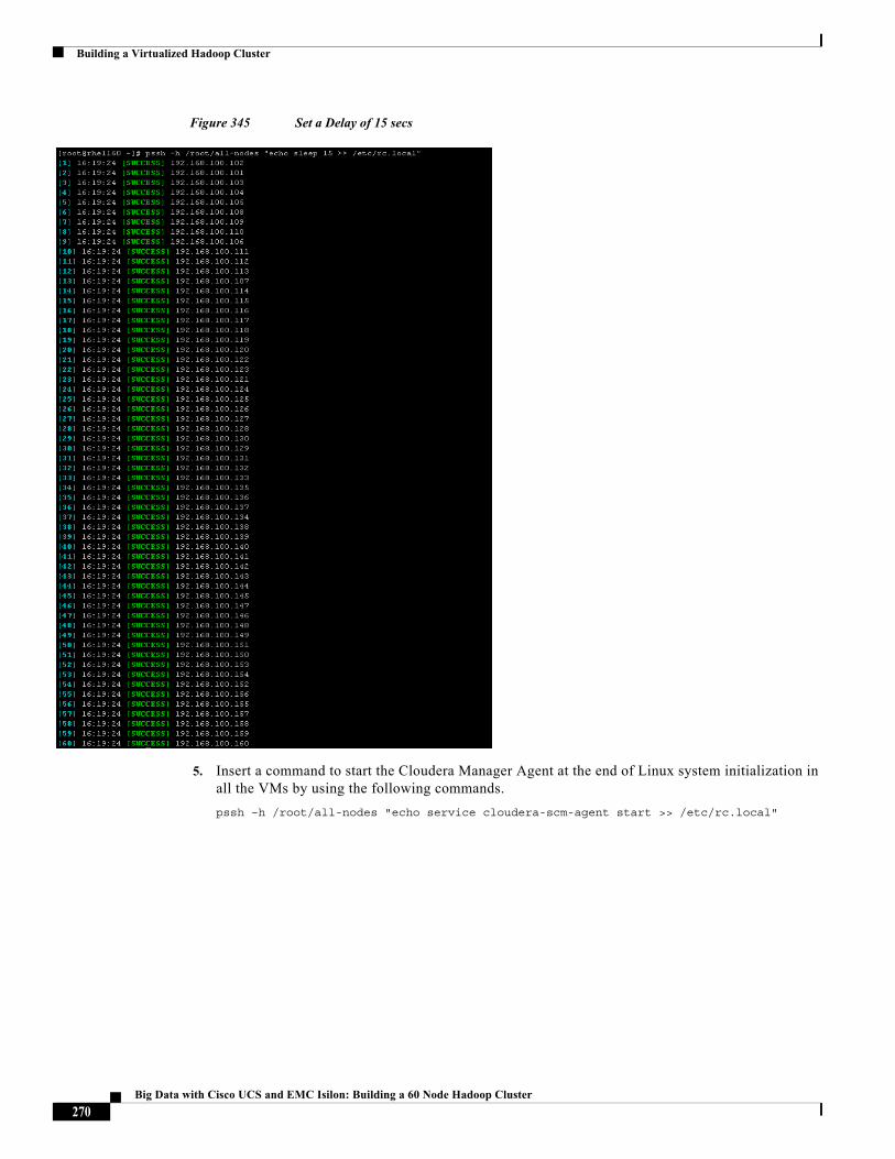
Building a Virtualized Hadoop Cluster
Figure 345 Set a Delay of 15 secs
5. Insert a command to start the Cloudera Manager Agent at the end of Linux system initialization in all the VMs by using the following commands.
pssh –h /root/all-nodes "echo service cloudera-scm-agent start >> /etc/rc.local"
270Big Data with Cisco UCS and EMC Isilon: Building a 60 Node Hadoop Cluster
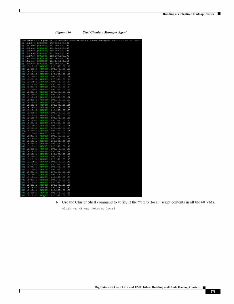
Building a Virtualized Hadoop Cluster
Figure 346 Start Cloudera Manager Agent
6. Use the Cluster Shell command to verify if the “/etc/rc.local” script contents in all the 60 VMs.
clush -a -B cat /etc/rc.local
271Big Data with Cisco UCS and EMC Isilon: Building a 60 Node Hadoop Cluster
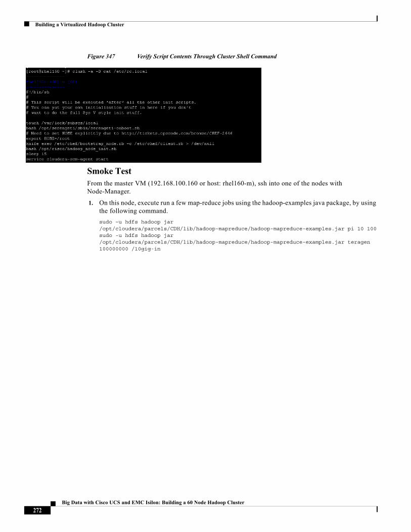
Building a Virtualized Hadoop Cluster
Figure 347 Verify Script Contents Through Cluster Shell Command
Smoke TestFrom the master VM (192.168.100.160 or host: rhel160-m), ssh into one of the nodes with Node-Manager.
1. On this node, execute run a few map-reduce jobs using the hadoop-examples java package, by using the following command.
sudo –u hdfs hadoop jar /opt/cloudera/parcels/CDH/lib/hadoop-mapreduce/hadoop-mapreduce-examples.jar pi 10 100sudo -u hdfs hadoop jar /opt/cloudera/parcels/CDH/lib/hadoop-mapreduce/hadoop-mapreduce-examples.jar teragen 100000000 /10gig-in
272Big Data with Cisco UCS and EMC Isilon: Building a 60 Node Hadoop Cluster
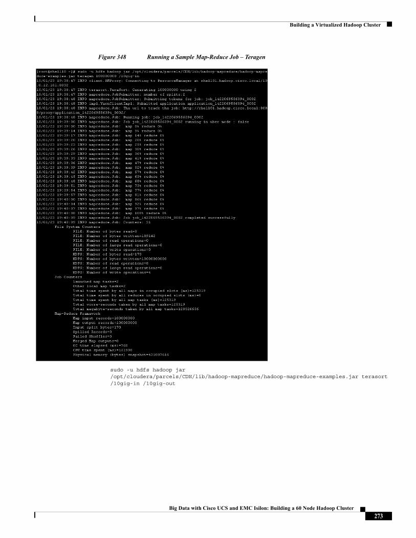
Building a Virtualized Hadoop Cluster
Figure 348 Running a Sample Map-Reduce Job – Teragen
sudo -u hdfs hadoop jar /opt/cloudera/parcels/CDH/lib/hadoop-mapreduce/hadoop-mapreduce-examples.jar terasort /10gig-in /10gig-out
273Big Data with Cisco UCS and EMC Isilon: Building a 60 Node Hadoop Cluster
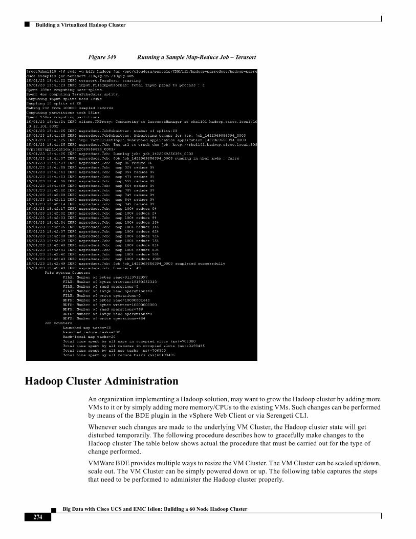
Building a Virtualized Hadoop Cluster
Figure 349 Running a Sample Map-Reduce Job – Terasort
Hadoop Cluster Administration
An organization implementing a Hadoop solution, may want to grow the Hadoop cluster by adding more VMs to it or by simply adding more memory/CPUs to the existing VMs. Such changes can be performed by means of the BDE plugin in the vSphere Web Client or via Serengeti CLI.
Whenever such changes are made to the underlying VM Cluster, the Hadoop cluster state will get disturbed temporarily. The following procedure describes how to gracefully make changes to the Hadoop cluster The table below shows actual the procedure that must be carried out for the type of change performed.
VMWare BDE provides multiple ways to resize the VM Cluster. The VM Cluster can be scaled up/down, scale out. The VM Cluster can be simply powered down or up. The following table captures the steps that need to be performed to administer the Hadoop cluster properly.
274Big Data with Cisco UCS and EMC Isilon: Building a 60 Node Hadoop Cluster
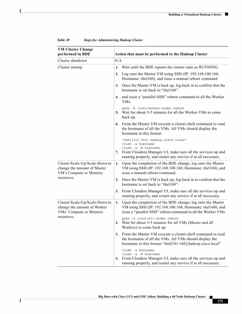
Building a Virtualized Hadoop Cluster
Table 20 Steps for Administering Hadoop Cluster
VM Cluster Change performed in BDE Action that must be performed to the Hadoop Cluster
Cluster shutdown N/A
Cluster startup 1. Wait until the BDE reports the cluster state as RUNNING.
2. Log onto the Master VM using SSH (IP: 192.168.100.160, Hostname: rhel160), and issue a manual reboot command.
3. Once the Master VM is back up, log back in to confirm that the hostname is set back to “rhel160”.
4. and issue a “parallel-SSH” reboot command to all the Worker VMs.
pssh –h /root/worker-nodes reboot
5. Wait for about 3-5 minutes for all the Worker-VMs to come back up.
6. From the Master VM execute a cluster-shell command to read the hostname of all the VMs. All VMs should display the hostname in this format.
“rhel[101-160].hadoop.cisco.local”clush -a hostnameclush -a -B hostname
7. From Cloudera Manager UI, make sure all the services up and running properly, and restart any service if at all necessary.
Cluster Scale-Up/Scale-Down to change the amount of Master VM’s Compute or Memory resources.
1. Upon the completion of the BDE change, log onto the Master VM using SSH (IP: 192.168.100.160, Hostname: rhel160), and issue a manual reboot command.
2. Once the Master VM is back up, log back in to confirm that the hostname is set back to “rhel160”.
3. From Cloudera Manager UI, make sure all the services up and running properly, and restart any service if at all necessary.
Cluster Scale-Up/Scale-Down to change the amount of Worker VMs’ Compute or Memory resources.
1. Upon the completion of the BDE change, log onto the Master VM using SSH (IP: 192.168.100.160, Hostname: rhel160), and issue a “parallel-SSH” reboot command to all the Worker VMs.
pssh –h /root/all-nodes reboot
2. Wait for about 3-5 minutes for all VMs (Master and all Workers) to come back up.
3. From the Master VM execute a cluster-shell command to read the hostname of all the VMs. All VMs should display the hostname in this format “rhel[101-160].hadoop.cisco.local”
clush -a hostnameclush -a -B hostname
4. From Cloudera Manager UI, make sure all the services up and running properly, and restart any service if at all necessary.
275Big Data with Cisco UCS and EMC Isilon: Building a 60 Node Hadoop Cluster
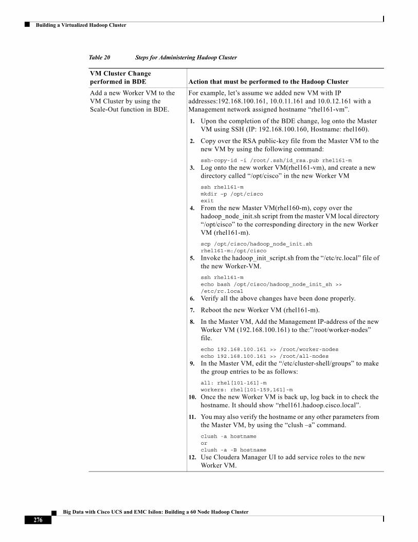
Building a Virtualized Hadoop Cluster
Add a new Worker VM to the VM Cluster by using the Scale-Out function in BDE.
For example, let’s assume we added new VM with IP addresses:192.168.100.161, 10.0.11.161 and 10.0.12.161 with a Management network assigned hostname “rhel161-vm”.
1. Upon the completion of the BDE change, log onto the Master VM using SSH (IP: 192.168.100.160, Hostname: rhel160).
2. Copy over the RSA public-key file from the Master VM to the new VM by using the following command:
ssh-copy-id –i /root/.ssh/id_rsa.pub rhel161-m
3. Log onto the new worker VM(rhel161-vm), and create a new directory called “/opt/cisco” in the new Worker VM
ssh rhel161-mmkdir –p /opt/ciscoexit
4. From the new Master VM(rhel160-m), copy over the hadoop_node_init.sh script from the master VM local directory “/opt/cisco” to the corresponding directory in the new Worker VM (rhel161-m).
scp /opt/cisco/hadoop_node_init.sh rhel161-m:/opt/cisco
5. Invoke the hadoop_init_script.sh from the “/etc/rc.local” file of the new Worker-VM.
ssh rhel161-mecho bash /opt/cisco/hadoop_node_init_sh >> /etc/rc.local
6. Verify all the above changes have been done properly.
7. Reboot the new Worker VM (rhel161-m).
8. In the Master VM, Add the Management IP-address of the new Worker VM (192.168.100.161) to the:”/root/worker-nodes” file.
echo 192.168.100.161 >> /root/worker-nodesecho 192.168.100.161 >> /root/all-nodes
9. In the Master VM, edit the “/etc/cluster-shell/groups” to make the group entries to be as follows:
all: rhel[101-161]-mworkers: rhel[101-159,161]-m
10. Once the new Worker VM is back up, log back in to check the hostname. It should show “rhel161.hadoop.cisco.local”.
11. You may also verify the hostname or any other parameters from the Master VM, by using the “clush –a” command.
clush -a hostnameorclush -a -B hostname
12. Use Cloudera Manager UI to add service roles to the new Worker VM.
Table 20 Steps for Administering Hadoop Cluster
VM Cluster Change performed in BDE Action that must be performed to the Hadoop Cluster
276Big Data with Cisco UCS and EMC Isilon: Building a 60 Node Hadoop Cluster
Conclusion
Conclusion Hadoop has become the leading data processing and cost-effective analytics platform of recent times. The Cisco UCS and Isilon Scale-Out NAS along with VMware’s vSphere Big Data Extensions offer a flexible and scalable service-oriented model for enterprise Hadoop cluster deployments (Virtualized Hadoop) with an outlook to meet the growing needs. Virtualized Hadoop offers elasticity, flexibility, and multi-tenancy, which makes it an excellent platform for voluminous data processing. Cisco UCS along with VMware vSphere Big Data Extensions and Cloudera Manager make it easy to deploy and scale the Hadoop clusters to meet the changing needs of today’s enterprise customers. Cisco UCS and EMC Isilon’s scale-out architecture paves the way to achieve the Business Data Lake architecture by separating data from compute. In this architecture, the data can be analyzed by various compute node setup as per the analytics logic.
The configuration detailed in the document can be extended to clusters of various sizes depending on the application demands. Up to 48 servers (6 Chassis populated with Cisco UCS B200 M3 Blade Servers) and 24 Node S200 Cluster can be supported with no additional switching in a single Cisco UCS domain. Scaling beyond 48 servers can be accomplished by interconnecting multiple Cisco UCS domains using Nexus 5000/7000/9000 Series switches, and getting managed in a single pane using UCS Central.
DisclaimerThis solution has not been tested with Kerberos enabled. Although Kerberos is supported by Cloudera Manager for securing Hadoop clusters, this document does not address the procedures required to provision it. Please refer to the relevant Kerberos configuration documentations of Cloudera Manager and EMC Isilon for further details about how to incorporate Kerberos to secure this Hadoop deployment.
13. After the new VM (i.e. rhel161-m: 192.168.100.161) has been added to the Hadoop cluster, perform the Post-VM configuration steps on this VM. See (refer to the new section Change102).
14. Log onto the VM using SSH to 192.168.100.161.
15. Disable the automatic startup of the Cloudera Manager Agent in all the VMs by entering the following command:
chkconfig cloudera-scm-agent off
16. Introduce a delay of 15 seconds into initialization script “/etc/rc.local” of all VMs.
echo sleep 15 >> /etc/rc.local
17. Insert a command to start the Cloudera Manager Agent at the end of Linux system initialization by using the following command.
echo service cloudera-scm-agent start >> /etc/rc.local
Now the VM has been fully provisioned to serve as a Hadoop node.
Table 20 Steps for Administering Hadoop Cluster
VM Cluster Change performed in BDE Action that must be performed to the Hadoop Cluster
277Big Data with Cisco UCS and EMC Isilon: Building a 60 Node Hadoop Cluster
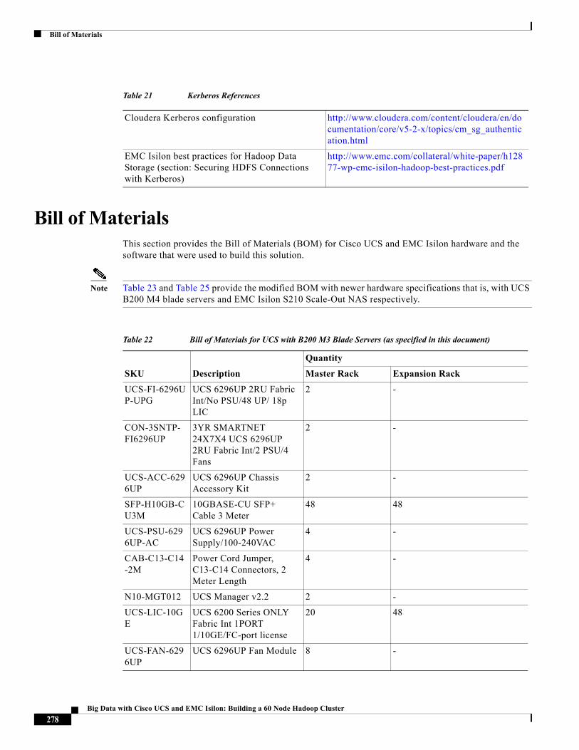
Bill of Materials
Bill of MaterialsThis section provides the Bill of Materials (BOM) for Cisco UCS and EMC Isilon hardware and the software that were used to build this solution.
Note Table 23 and Table 25 provide the modified BOM with newer hardware specifications that is, with UCS B200 M4 blade servers and EMC Isilon S210 Scale-Out NAS respectively.
Table 21 Kerberos References
Cloudera Kerberos configuration http://www.cloudera.com/content/cloudera/en/documentation/core/v5-2-x/topics/cm_sg_authentication.html
EMC Isilon best practices for Hadoop Data Storage (section: Securing HDFS Connections with Kerberos)
http://www.emc.com/collateral/white-paper/h12877-wp-emc-isilon-hadoop-best-practices.pdf
Table 22 Bill of Materials for UCS with B200 M3 Blade Servers (as specified in this document)
SKU Description
Quantity
Master Rack Expansion Rack
UCS-FI-6296UP-UPG
UCS 6296UP 2RU Fabric Int/No PSU/48 UP/ 18p LIC
2 -
CON-3SNTP-FI6296UP
3YR SMARTNET 24X7X4 UCS 6296UP 2RU Fabric Int/2 PSU/4 Fans
2 -
UCS-ACC-6296UP
UCS 6296UP Chassis Accessory Kit
2 -
SFP-H10GB-CU3M
10GBASE-CU SFP+ Cable 3 Meter
48 48
UCS-PSU-6296UP-AC
UCS 6296UP Power Supply/100-240VAC
4 -
CAB-C13-C14-2M
Power Cord Jumper, C13-C14 Connectors, 2 Meter Length
4 -
N10-MGT012 UCS Manager v2.2 2 -
UCS-LIC-10GE
UCS 6200 Series ONLY Fabric Int 1PORT 1/10GE/FC-port license
20 48
UCS-FAN-6296UP
UCS 6296UP Fan Module 8 -
278Big Data with Cisco UCS and EMC Isilon: Building a 60 Node Hadoop Cluster
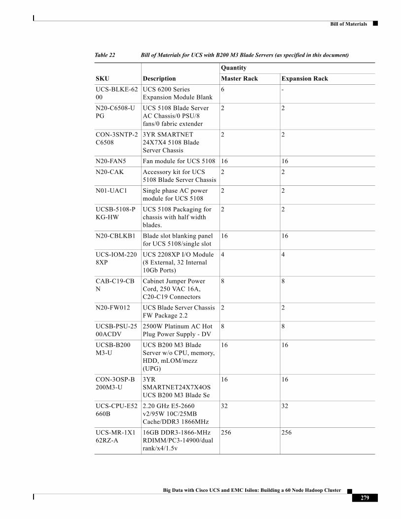
Bill of Materials
UCS-BLKE-6200
UCS 6200 Series Expansion Module Blank
6 -
N20-C6508-UPG
UCS 5108 Blade Server AC Chassis/0 PSU/8 fans/0 fabric extender
2 2
CON-3SNTP-2C6508
3YR SMARTNET 24X7X4 5108 Blade Server Chassis
2 2
N20-FAN5 Fan module for UCS 5108 16 16
N20-CAK Accessory kit for UCS 5108 Blade Server Chassis
2 2
N01-UAC1 Single phase AC power module for UCS 5108
2 2
UCSB-5108-PKG-HW
UCS 5108 Packaging for chassis with half width blades.
2 2
N20-CBLKB1 Blade slot blanking panel for UCS 5108/single slot
16 16
UCS-IOM-2208XP
UCS 2208XP I/O Module (8 External, 32 Internal 10Gb Ports)
4 4
CAB-C19-CBN
Cabinet Jumper Power Cord, 250 VAC 16A, C20-C19 Connectors
8 8
N20-FW012 UCS Blade Server Chassis FW Package 2.2
2 2
UCSB-PSU-2500ACDV
2500W Platinum AC Hot Plug Power Supply - DV
8 8
UCSB-B200 M3-U
UCS B200 M3 Blade Server w/o CPU, memory, HDD, mLOM/mezz (UPG)
16 16
CON-3OSP-B200M3-U
3YR SMARTNET24X7X4OS UCS B200 M3 Blade Se
16 16
UCS-CPU-E52660B
2.20 GHz E5-2660 v2/95W 10C/25MB Cache/DDR3 1866MHz
32 32
UCS-MR-1X162RZ-A
16GB DDR3-1866-MHz RDIMM/PC3-14900/dual rank/x4/1.5v
256 256
Table 22 Bill of Materials for UCS with B200 M3 Blade Servers (as specified in this document)
SKU Description
Quantity
Master Rack Expansion Rack
279Big Data with Cisco UCS and EMC Isilon: Building a 60 Node Hadoop Cluster
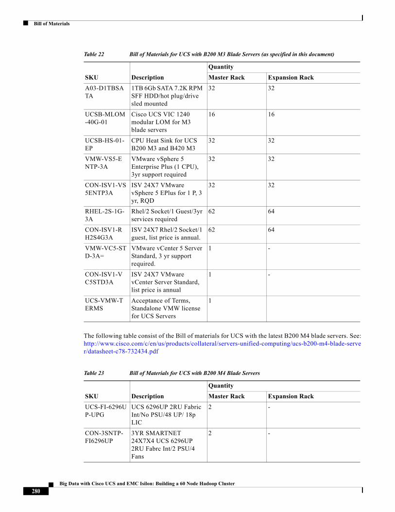
Bill of Materials
The following table consist of the Bill of materials for UCS with the latest B200 M4 blade servers. See: http://www.cisco.com/c/en/us/products/collateral/servers-unified-computing/ucs-b200-m4-blade-server/datasheet-c78-732434.pdf
A03-D1TBSATA
1TB 6Gb SATA 7.2K RPM SFF HDD/hot plug/drive sled mounted
32 32
UCSB-MLOM-40G-01
Cisco UCS VIC 1240 modular LOM for M3 blade servers
16 16
UCSB-HS-01-EP
CPU Heat Sink for UCS B200 M3 and B420 M3
32 32
VMW-VS5-ENTP-3A
VMware vSphere 5 Enterprise Plus (1 CPU), 3yr support required
32 32
CON-ISV1-VS5ENTP3A
ISV 24X7 VMware vSphere 5 EPlus for 1 P, 3 yr, RQD
32 32
RHEL-2S-1G-3A
Rhel/2 Socket/1 Guest/3yr services required
62 64
CON-ISV1-RH2S4G3A
ISV 24X7 Rhel/2 Socket/1 guest, list price is annual.
62 64
VMW-VC5-STD-3A=
VMware vCenter 5 Server Standard, 3 yr support required.
1 -
CON-ISV1-VC5STD3A
ISV 24X7 VMware vCenter Server Standard, list price is annual
1 -
UCS-VMW-TERMS
Acceptance of Terms, Standalone VMW license for UCS Servers
1
Table 22 Bill of Materials for UCS with B200 M3 Blade Servers (as specified in this document)
SKU Description
Quantity
Master Rack Expansion Rack
Table 23 Bill of Materials for UCS with B200 M4 Blade Servers
SKU Description
Quantity
Master Rack Expansion Rack
UCS-FI-6296UP-UPG
UCS 6296UP 2RU Fabric Int/No PSU/48 UP/ 18p LIC
2 -
CON-3SNTP-FI6296UP
3YR SMARTNET 24X7X4 UCS 6296UP 2RU Fabrc Int/2 PSU/4 Fans
2 -
280Big Data with Cisco UCS and EMC Isilon: Building a 60 Node Hadoop Cluster
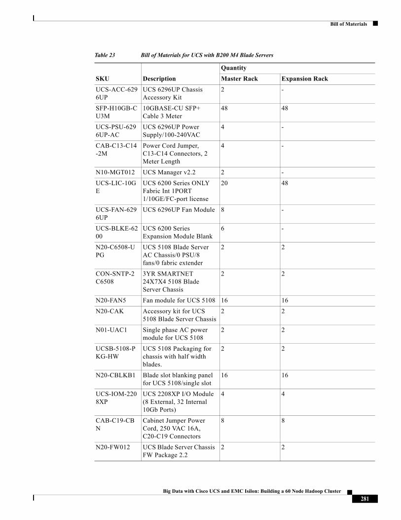
Bill of Materials
UCS-ACC-6296UP
UCS 6296UP Chassis Accessory Kit
2 -
SFP-H10GB-CU3M
10GBASE-CU SFP+ Cable 3 Meter
48 48
UCS-PSU-6296UP-AC
UCS 6296UP Power Supply/100-240VAC
4 -
CAB-C13-C14-2M
Power Cord Jumper, C13-C14 Connectors, 2 Meter Length
4 -
N10-MGT012 UCS Manager v2.2 2 -
UCS-LIC-10GE
UCS 6200 Series ONLY Fabric Int 1PORT 1/10GE/FC-port license
20 48
UCS-FAN-6296UP
UCS 6296UP Fan Module 8 -
UCS-BLKE-6200
UCS 6200 Series Expansion Module Blank
6 -
N20-C6508-UPG
UCS 5108 Blade Server AC Chassis/0 PSU/8 fans/0 fabric extender
2 2
CON-SNTP-2C6508
3YR SMARTNET 24X7X4 5108 Blade Server Chassis
2 2
N20-FAN5 Fan module for UCS 5108 16 16
N20-CAK Accessory kit for UCS 5108 Blade Server Chassis
2 2
N01-UAC1 Single phase AC power module for UCS 5108
2 2
UCSB-5108-PKG-HW
UCS 5108 Packaging for chassis with half width blades.
2 2
N20-CBLKB1 Blade slot blanking panel for UCS 5108/single slot
16 16
UCS-IOM-2208XP
UCS 2208XP I/O Module (8 External, 32 Internal 10Gb Ports)
4 4
CAB-C19-CBN
Cabinet Jumper Power Cord, 250 VAC 16A, C20-C19 Connectors
8 8
N20-FW012 UCS Blade Server Chassis FW Package 2.2
2 2
Table 23 Bill of Materials for UCS with B200 M4 Blade Servers
SKU Description
Quantity
Master Rack Expansion Rack
281Big Data with Cisco UCS and EMC Isilon: Building a 60 Node Hadoop Cluster
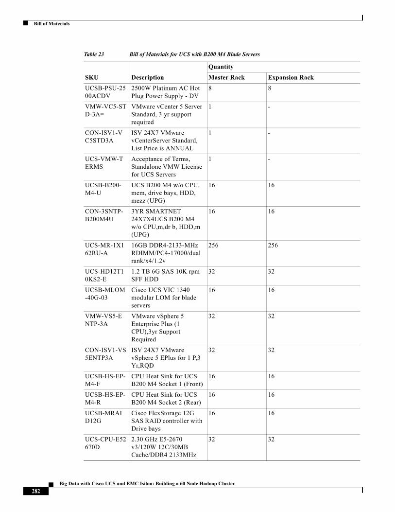
Bill of Materials
UCSB-PSU-2500ACDV
2500W Platinum AC Hot Plug Power Supply - DV
8 8
VMW-VC5-STD-3A=
VMware vCenter 5 Server Standard, 3 yr support required
1 -
CON-ISV1-VC5STD3A
ISV 24X7 VMware vCenterServer Standard, List Price is ANNUAL
1 -
UCS-VMW-TERMS
Acceptance of Terms, Standalone VMW License for UCS Servers
1 -
UCSB-B200-M4-U
UCS B200 M4 w/o CPU, mem, drive bays, HDD, mezz (UPG)
16 16
CON-3SNTP-B200M4U
3YR SMARTNET 24X7X4UCS B200 M4 w/o CPU,m,dr b, HDD,m (UPG)
16 16
UCS-MR-1X162RU-A
16GB DDR4-2133-MHz RDIMM/PC4-17000/dual rank/x4/1.2v
256 256
UCS-HD12T10KS2-E
1.2 TB 6G SAS 10K rpm SFF HDD
32 32
UCSB-MLOM-40G-03
Cisco UCS VIC 1340 modular LOM for blade servers
16 16
VMW-VS5-ENTP-3A
VMware vSphere 5 Enterprise Plus (1 CPU),3yr Support Required
32 32
CON-ISV1-VS5ENTP3A
ISV 24X7 VMware vSphere 5 EPlus for 1 P,3 Yr,RQD
32 32
UCSB-HS-EP-M4-F
CPU Heat Sink for UCS B200 M4 Socket 1 (Front)
16 16
UCSB-HS-EP-M4-R
CPU Heat Sink for UCS B200 M4 Socket 2 (Rear)
16 16
UCSB-MRAID12G
Cisco FlexStorage 12G SAS RAID controller with Drive bays
16 16
UCS-CPU-E52670D
2.30 GHz E5-2670 v3/120W 12C/30MB Cache/DDR4 2133MHz
32 32
Table 23 Bill of Materials for UCS with B200 M4 Blade Servers
SKU Description
Quantity
Master Rack Expansion Rack
282Big Data with Cisco UCS and EMC Isilon: Building a 60 Node Hadoop Cluster
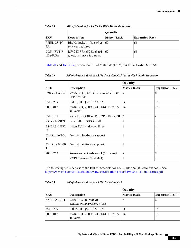
Bill of Materials
Table 24 and Table 25 provide the Bill of Materials (BOM) for Isilon Scale-Out NAS.
The following table consist of the Bill of materials for EMC Isilon S210 Scale-out NAS. See: http://www.emc.com/collateral/hardware/specification-sheet/h10690-ss-isilon-s-series.pdf
RHEL-2S-1G-3A
Rhel/2 Socket/1 Guest/3yr services required
62 64
CON-ISV1-RH2S4G3A
ISV 24X7 Rhel/2 Socket/1 guest, list price is annual
62 64
Table 23 Bill of Materials for UCS with B200 M4 Blade Servers
SKU Description
Quantity
Master Rack Expansion Rack
Table 24 Bill of Materials for Isilon S200 Scale-Out NAS (as specified in this document)
SKU Description
Quantity
Master Rack Expansion Rack
S200-SAS-S32 S200-19.8T+400G SSD/96G/2x10GE SFP+2x1GE
8 8
851-0209 Cable, IB, QSFP-CX4, 3M 16 16
800-0012 PWRCRD, 2, IEC320 C14-C13, 208V universal
16 16
851-0151 Switch IB QDR 48 Port 2PS 10U -120 2 -
PSINST-ESRS zero dollar ESRS install 1 1
PS-BAS-INIS2U
Isilon 2U Installation Base 1 1
M-PREHWI-001
Premium hardware support 1 1
M-PRESWI-001
Premium software support 1 1
200-0262 SmartConnect Advanced (Software) 8 8
HDFS licenses (included) 1 -
Table 25 Bill of Materials for Isilon S210 Scale-Out NAS
SKU Description
Quantity
Master Rack Expansion Rack
S210-SAS-S11 S210-13.8TB+800GB SSD/256G/2x10GE+2x1GE
8 8
851-0209 Cable, IB, QSFP-CX4, 3M 16 16
800-0012 PWRCRD, 2, IEC320 C14-C13, 208V universal
16 16
283Big Data with Cisco UCS and EMC Isilon: Building a 60 Node Hadoop Cluster
Appendix
Table 26 provides the BOM for Cloudera Enterprise License.
Appendix
Script for Creating Hadoop Users on Isilon OneFS### The script has been copied from Github page: https://github.com/claudiofahey/isilon-hadoop-tools/releases on 10/26/2014.#!/bin/bash############################################################################# Script to create Hadoop users on Isilon.## Must be run on Isilon system as root.###########################################################################
if [ -z "$BASH_VERSION" ] ; then # probably using zsh... echo "Script not run from bash -- reinvoking under bash" bash "$0" exit $?fi
declare -a ERRORLIST=()
DIST=""STARTUID=1000STARTGID=1000ZONE="System"
#set -x
851-0151 Switch IB QDR 48 Port 2PS 10U -120 2 -
PSINST-ESRS zero dollar ESRS install 1 1
PS-BAS-INIS2U
Isilon 2U Installation Base 1 1
M-PREHWI-001
Premium hardware support 1 1
M-PRESWI-001
Premium software support 1 1
200-0262 SmartConnect Advanced (Software) 8 8
HDFS licenses (included) 1 -
Table 25 Bill of Materials for Isilon S210 Scale-Out NAS
SKU Description
Quantity
Master Rack Expansion Rack
Table 26 Bill of Materials for Cloudera Enterprise License
SKU Description Master Rack Expansion Rack
UCS-BD-CEDN= Cloudera Enterprise 60 instances 64 instances
284Big Data with Cisco UCS and EMC Isilon: Building a 60 Node Hadoop Cluster
Appendix
function banner() { echo "##################################################################################" echo "## $*" echo "##################################################################################"}
function usage() { echo "$0 --dist <cdh|hwx|phd> --startgid <GID>] [--startuid <UID>] [--zone <ZONE>]" exit 1}
function fatal() { echo "FATAL: $*" exit 1}
function warn() { echo "ERROR: $*" ERRORLIST[${#ERRORLIST[@]}]="$*"}
function addError() { ERRORLIST+=("$*")}
function yesno() { [ -n "$1" ] && myPrompt=">>> $1 (y/n)? " [ -n "$1" ] || myPrompt=">>> Please enter yes/no: " read -rp "$myPrompt" yn [ "z${yn:0:1}" = "zy" -o "z${yn:0:1}" = "zY" ] && return 0# exit "DEBUG: returning false from function yesno" return 1}
function uidInUse() { isi auth users view --uid $1 --zone $2 > /dev/null 2>&1}
function userExists() { isi auth users view $1 --zone $2 > /dev/null 2>&1}
function groupExists() { isi auth groups view $1 --zone $2 > /dev/null 2>&1}
function gidInUse() { isi auth groups view --gid $1 --zone $2 > /dev/null 2>&1}
function getUidFromUser() { local uid uid=$(isi auth users view $1 --zone $2 | awk '/^ *UID:/ {print $2}') echo $uid}
function getUserFromUid() { local user user=$(isi auth users view --uid $1 --zone $2 | head -1 | awk '/^ *Name:/ {print $2}') echo $user}
285Big Data with Cisco UCS and EMC Isilon: Building a 60 Node Hadoop Cluster
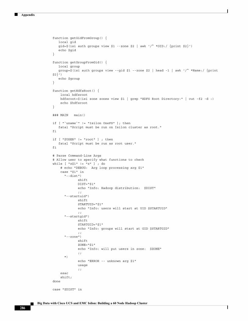
Appendix
function getGidFromGroup() { local gid gid=$(isi auth groups view $1 --zone $2 | awk '/^ *GID:/ {print $2}') echo $gid}
function getGroupFromGid() { local group group=$(isi auth groups view --gid $1 --zone $2 | head -1 | awk '/^ *Name:/ {print $2}') echo $group}
function getHdfsRoot() { local hdfsroot hdfsroot=$(isi zone zones view $1 | grep "HDFS Root Directory:" | cut -f2 -d :) echo $hdfsroot}
### MAIN main()
if [ "`uname`" != "Isilon OneFS" ]; then fatal "Script must be run on Isilon cluster as root."fi
if [ "$USER" != "root" ] ; then fatal "Script must be run as root user."fi
# Parse Command-Line Args# Allow user to specify what functions to checkwhile [ "z$1" != "z" ] ; do # echo "DEBUG: Arg loop processing arg $1" case "$1" in "--dist") shift DIST="$1" echo "Info: Hadoop distribution: $DIST" ;; "--startuid") shift STARTUID="$1" echo "Info: users will start at UID $STARTUID" ;; "--startgid") shift STARTGID="$1" echo "Info: groups will start at GID $STARTGID" ;; "--zone") shift ZONE="$1" echo "Info: will put users in zone: $ZONE" ;; *) echo "ERROR -- unknown arg $1" usage ;; esac shift;done
case "$DIST" in
286Big Data with Cisco UCS and EMC Isilon: Building a 60 Node Hadoop Cluster
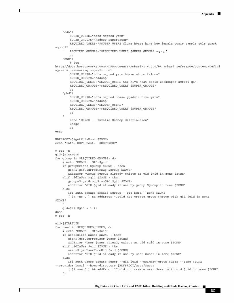
Appendix
"cdh") SUPER_USERS="hdfs mapred yarn" SUPER_GROUPS="hadoop supergroup" REQUIRED_USERS="$SUPER_USERS flume hbase hive hue impala oozie sample solr spark sqoop2" REQUIRED_GROUPS="$REQUIRED_USERS $SUPER_GROUPS sqoop" ;; "hwx") # See http://docs.hortonworks.com/HDPDocuments/Ambari-1.6.0.0/bk_ambari_reference/content/Defining-service-users-groups-2x.html SUPER_USERS="hdfs mapred yarn hbase storm falcon" SUPER_GROUPS="hadoop" REQUIRED_USERS="$SUPER_USERS tez hive hcat oozie zookeeper ambari-qa" REQUIRED_GROUPS="$REQUIRED_USERS $SUPER_GROUPS" ;; "phd") SUPER_USERS="hdfs mapred hbase gpadmin hive yarn" SUPER_GROUPS="hadoop" REQUIRED_USERS="$SUPER_USERS" REQUIRED_GROUPS="$REQUIRED_USERS $SUPER_GROUPS" ;; *) echo "ERROR -- Invalid Hadoop distribution" usage ;;esac
HDFSROOT=$(getHdfsRoot $ZONE)echo "Info: HDFS root: $HDFSROOT"
# set -xgid=$STARTGIDfor group in $REQUIRED_GROUPS; do # echo "DEBUG: GID=$gid" if groupExists $group $ZONE ; then gid=$(getGidFromGroup $group $ZONE) addError "Group $group already exists at gid $gid in zone $ZONE" elif gidInUse $gid $ZONE ; then group=$(getGroupFromGid $gid $ZONE) addError "GID $gid already in use by group $group in zone $ZONE" else isi auth groups create $group --gid $gid --zone $ZONE [ $? -ne 0 ] && addError "Could not create group $group with gid $gid in zone $ZONE" fi gid=$(( $gid + 1 ))done# set +x
uid=$STARTUIDfor user in $REQUIRED_USERS; do # echo "DEBUG: UID=$uid" if userExists $user $ZONE ; then uid=$(getUidFromUser $user $ZONE) addError "User $user already exists at uid $uid in zone $ZONE" elif uidInUse $uid $ZONE ; then user=$(getUserFromUid $uid $ZONE) addError "UID $uid already in use by user $user in zone $ZONE" else isi auth users create $user --uid $uid --primary-group $user --zone $ZONE --provider local --home-directory $HDFSROOT/user/$user [ $? -ne 0 ] && addError "Could not create user $user with uid $uid in zone $ZONE" fi
287Big Data with Cisco UCS and EMC Isilon: Building a 60 Node Hadoop Cluster
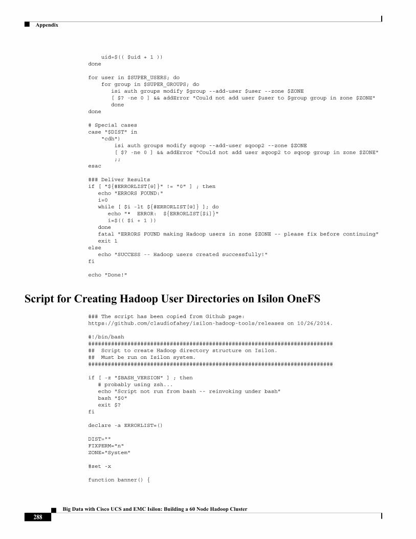
Appendix
uid=$(( $uid + 1 ))done
for user in $SUPER_USERS; do for group in $SUPER_GROUPS; do isi auth groups modify $group --add-user $user --zone $ZONE [ $? -ne 0 ] && addError "Could not add user $user to $group group in zone $ZONE" donedone
# Special casescase "$DIST" in "cdh") isi auth groups modify sqoop --add-user sqoop2 --zone $ZONE [ $? -ne 0 ] && addError "Could not add user sqoop2 to sqoop group in zone $ZONE" ;;esac
### Deliver Resultsif [ "${#ERRORLIST[@]}" != "0" ] ; then echo "ERRORS FOUND:" i=0 while [ $i -lt ${#ERRORLIST[@]} ]; do echo "* ERROR: ${ERRORLIST[$i]}" i=$(( $i + 1 )) done fatal "ERRORS FOUND making Hadoop users in zone $ZONE -- please fix before continuing" exit 1else echo "SUCCESS -- Hadoop users created successfully!"fi
echo "Done!"
Script for Creating Hadoop User Directories on Isilon OneFS### The script has been copied from Github page: https://github.com/claudiofahey/isilon-hadoop-tools/releases on 10/26/2014.
#!/bin/bash############################################################################# Script to create Hadoop directory structure on Isilon.## Must be run on Isilon system.###########################################################################
if [ -z "$BASH_VERSION" ] ; then # probably using zsh... echo "Script not run from bash -- reinvoking under bash" bash "$0" exit $?fi
declare -a ERRORLIST=()
DIST=""FIXPERM="n"ZONE="System"
#set -x
function banner() {
288Big Data with Cisco UCS and EMC Isilon: Building a 60 Node Hadoop Cluster
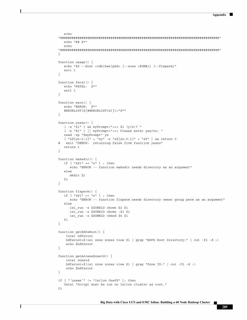
Appendix
echo "##################################################################################" echo "## $*" echo "##################################################################################"}
function usage() { echo "$0 --dist <cdh|hwx|phd> [--zone <ZONE>] [--fixperm]" exit 1}
function fatal() { echo "FATAL: $*" exit 1}
function warn() { echo "ERROR: $*" ERRORLIST[${#ERRORLIST[@]}]="$*"}
function yesno() { [ -n "$1" ] && myPrompt=">>> $1 (y/n)? " [ -n "$1" ] || myPrompt=">>> Please enter yes/no: " read -rp "$myPrompt" yn [ "z${yn:0:1}" = "zy" -o "z${yn:0:1}" = "zY" ] && return 0# exit "DEBUG: returning false from function yesno" return 1}
function makedir() { if [ "z$1" == "z" ] ; then echo "ERROR -- function makedir needs directory as an argument" else mkdir $1 fi} function fixperm() { if [ "z$1" == "z" ] ; then echo "ERROR -- function fixperm needs directory owner group perm as an argument" else isi_run -z $ZONEID chown $2 $1 isi_run -z $ZONEID chown :$3 $1 isi_run -z $ZONEID chmod $4 $1 fi}
function getHdfsRoot() { local hdfsroot hdfsroot=$(isi zone zones view $1 | grep "HDFS Root Directory:" | cut -f2 -d :) echo $hdfsroot} function getAccessZoneId() { local zoneid hdfsroot=$(isi zone zones view $1 | grep "Zone ID:" | cut -f2 -d :) echo $hdfsroot} if [ "`uname`" != "Isilon OneFS" ]; then fatal "Script must be run on Isilon cluster as root."fi
289Big Data with Cisco UCS and EMC Isilon: Building a 60 Node Hadoop Cluster

Appendix
if [ "$USER" != "root" ] ; then fatal "Script must be run as root user."fi
# Parse Command-Line Args # Allow user to specify what functions to check while [ "z$1" != "z" ] ; do # echo "DEBUG: Arg loop processing arg $1" case "$1" in "--dist") shift DIST="$1" echo "Info: Hadoop distribution: $DIST" ;; "--zone") shift ZONE="$1" echo "Info: will use users in zone: $ZONE" ;; "--fixperm") echo "Info: will fix permissions and owners on existing directories" FIXPERM="y" ;; *) echo "ERROR -- unknown arg $1" usage ;; esac shift;done
declare -a dirList
case "$DIST" in "cdh") # Format is: dirname#perm#owner#group dirList=(\ "/#755#hdfs#hadoop" \ "/hbase#755#hbase#hbase" \ "/solr#775#solr#solr" \ "/tmp#1777#hdfs#supergroup" \ "/tmp/logs#1777#mapred#hadoop" \ "/user#755#hdfs#supergroup" \ "/user/history#777#mapred#hadoop" \ "/user/hive#775#hive#hive" \ "/user/hive/warehouse#1777#hive#hive" \ "/user/hue#755#hue#hue" \ "/user/hue/.cloudera_manager_hive_metastore_canary#777#hue#hue" \ "/user/impala#775#impala#impala" \ "/user/oozie#775#oozie#oozie" \ "/user/spark#755#spark#spark" \ "/user/spark/applicationHistory#1777#spark#spark" \ "/user/sqoop2#775#sqoop2#sqoop" \ ) ;; "hwx") # Format is: dirname#perm#owner#group dirList=(\ "/#755#hdfs#hadoop" \ "/tmp#1777#hdfs#hdfs" \ "/user#755#hdfs#hdfs" \ "/user/ambari-qa#770#ambari-qa#hdfs" \ "/user/hcat#755#hcat#hdfs" \ "/user/hive#700#hive#hdfs" \
290Big Data with Cisco UCS and EMC Isilon: Building a 60 Node Hadoop Cluster
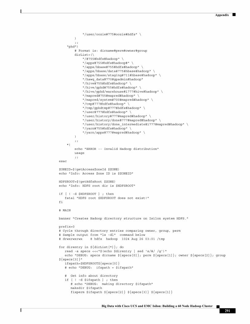
Appendix
"/user/oozie#775#oozie#hdfs" \ ) ;; "phd") # Format is: dirname#perm#owner#group dirList=(\ "/#755#hdfs#hadoop" \ "/apps#755#hdfs#hadoop#" \ "/apps/hbase#755#hdfs#hadoop" \ "/apps/hbase/data#775#hbase#hadoop" \ "/apps/hbase/staging#711#hbase#hadoop" \ "/hawq_data#770#gpadmin#hadoop" "/hive#755#hdfs#hadoop" \ "/hive/gphd#755#hdfs#hadoop" \ "/hive/gphd/warehouse#1777#hive#hadoop" \ "/mapred#755#mapred#hadoop" \ "/mapred/system#700#mapred#hadoop" \ "/tmp#777#hdfs#hadoop" \ "/tmp/gphdtmp#777#hdfs#hadoop" \ "/user#777#hdfs#hadoop" \ "/user/history#777#mapred#hadoop" \ "/user/history/done#777#mapred#hadoop" \ "/user/history/done_intermediate#1777#mapred#hadoop" \ "/yarn#755#hdfs#hadoop" \ "/yarn/apps#777#mapred#hadoop" \ ) ;; *) echo "ERROR -- Invalid Hadoop distribution" usage ;;esac
ZONEID=$(getAccessZoneId $ZONE)echo "Info: Access Zone ID is $ZONEID"
HDFSROOT=$(getHdfsRoot $ZONE)echo "Info: HDFS root dir is $HDFSROOT"
if [ ! -d $HDFSROOT ] ; then fatal "HDFS root $HDFSROOT does not exist!"fi
# MAIN
banner "Creates Hadoop directory structure on Isilon system HDFS."
prefix=0# Cycle through directory entries comparing owner, group, perm# Sample output from "ls -dl" command below# drwxrwxrwx 8 hdfs hadoop 1024 Aug 26 03:01 /tmp
for direntry in ${dirList[*]}; do read -a specs <<<"$(echo $direntry | sed 's/#/ /g')" echo "DEBUG: specs dirname ${specs[0]}; perm ${specs[1]}; owner ${specs[2]}; group ${specs[3]}" ifspath=$HDFSROOT${specs[0]} # echo "DEBUG: ifspath = $ifspath"
# Get info about directory if [ ! -d $ifspath ] ; then # echo "DEBUG: making directory $ifspath" makedir $ifspath fixperm $ifspath ${specs[2]} ${specs[3]} ${specs[1]}
291Big Data with Cisco UCS and EMC Isilon: Building a 60 Node Hadoop Cluster
Appendix
elif [ "$FIXPERM" == "y" ] ; then # echo "DEBUG: fixing directory perm $ifspath" fixperm $ifspath ${specs[2]} ${specs[3]} ${specs[1]} else warn "Directory $ifspath exists but no --fixperm not specified" fi
done
if [ "${#ERRORLIST[@]}" != "0" ] ; then echo "ERRORS FOUND:" i=0 while [ $i -lt ${#ERRORLIST[@]} ]; do echo "ERROR: ${ERRORLIST[$i]}" i=$(($i + 1)) done fatal "ERRORS FOUND making Hadoop admin directory structure -- please fix before continuing" exit 1else echo "SUCCESS -- Hadoop admin directory structure exists and has correct ownership and permissions"fi
echo "Done!"
292Big Data with Cisco UCS and EMC Isilon: Building a 60 Node Hadoop Cluster