biacore t200 getting started - duke university · the handbook, together with the ... • amine...
TRANSCRIPT

GE Healthcare
Biacore T200
Getting Started

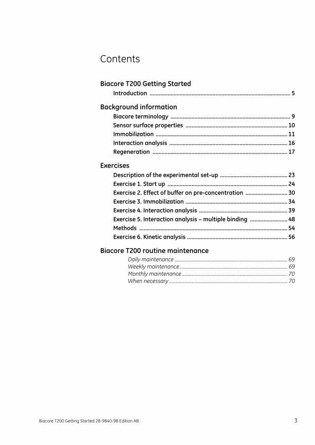
Contents
Biacore T200 Getting StartedIntroduction .............................................................................................. 5
Background informationBiacore terminology ................................................................................ 9Sensor surface properties .................................................................... 10Immobilization ........................................................................................ 11Interaction analysis ............................................................................... 16Regeneration .......................................................................................... 17
ExercisesDescription of the experimental set-up ............................................. 23Exercise 1. Start up ................................................................................ 24Exercise 2. Effect of buffer on pre-concentration ............................ 30Exercise 3. Immobilization .................................................................... 34Exercise 4. Interaction analysis ........................................................... 39Exercise 5. Interaction analysis – multiple binding ......................... 48Methods ................................................................................................... 54Exercise 6. Kinetic analysis ................................................................... 56
Biacore T200 routine maintenanceDaily maintenance ................................................................................................. 69Weekly maintenance............................................................................................. 69Monthly maintenance ........................................................................................... 70When necessary ...................................................................................................... 70
Biacore T200 Getting Started 28-9840-98 Edition AB 3

4 Biacore T200 Getting Started 28-9840-98 Edition AB
Biacore T200 Getting Started
Biacore T200 Getting Started
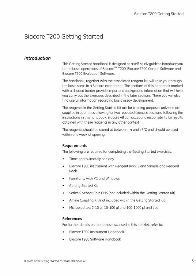
IntroductionThis Getting Started handbook is designed as a self-study guide to introduce you to the basic operations of BiacoreTM T200, Biacore T200 Control Software and Biacore T200 Evaluation Software.
The handbook, together with the associated reagent kit , will take you through the basic steps in a Biacore experiment. The sections of this handbook marked with a shaded border provide important background information that will help you carry out the exercises described in the later sections. There you will also find useful information regarding basic assay development.
The reagents in the Getting Started Kit are for training purposes only and are supplied in quantities allowing for two repeated exercise sessions, following the instructions in this handbook. Biacore AB can accept no responsibility for results obtained with these reagents in any other context.
The reagents should be stored at between +4 and +8°C and should be used within one week of opening.
RequirementsThe following are required for completing the Getting Started exercises:
• Time: approximately one day
• Biacore T200 instrument with Reagent Rack 2 and Sample and Reagent Rack
• Familiarity with PC and Windows
• Getting Started Kit
• Series S Sensor Chip CM5 (not included within the Getting Started Kit)
• Amine Coupling Kit (not included within the Getting Started Kit)
• Micropipettes; 2-10 µl, 10-100 µl and 100-1000 µl and tips
ReferencesFor further details on the topics discussed in this booklet, refer to:
• Biacore T200 Instrument Handbook
• Biacore T200 Software Handbook
Biacore T200 Getting Started 28-9840-98 Edition AB 5
Biacore T200 Getting StartedIntroduction
• Biacore Advisor Tutorial (CD-ROM)
• Sensor Surface Handbook
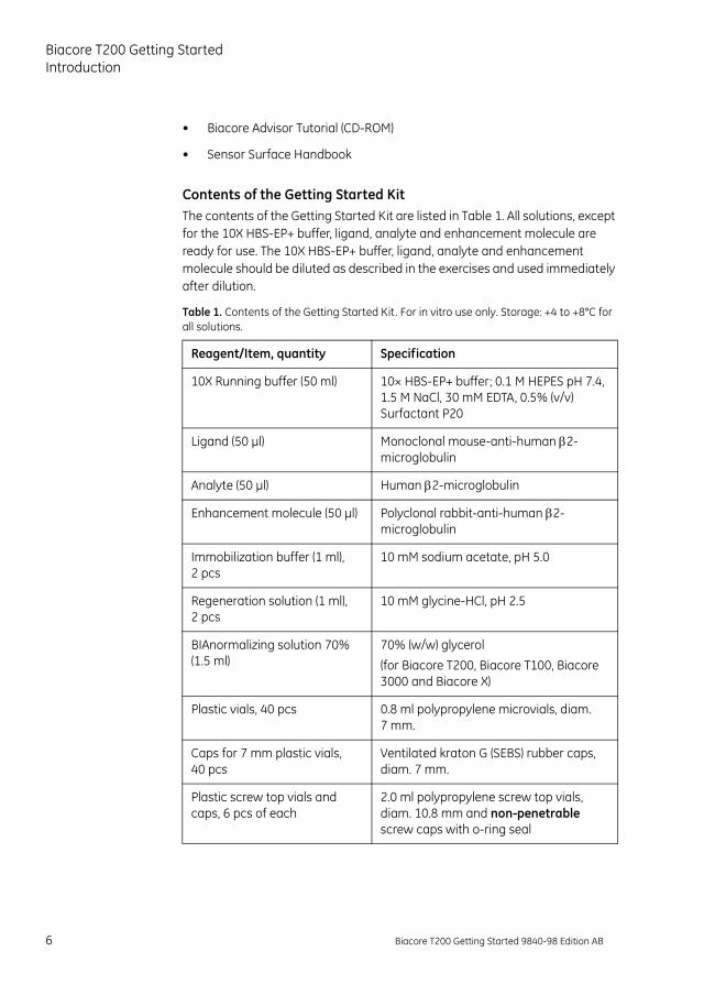
Contents of the Getting Started KitThe contents of the Getting Started Kit are listed in Table 1. All solutions, except for the 10X HBS-EP+ buffer, ligand, analyte and enhancement molecule are ready for use. The 10X HBS-EP+ buffer, ligand, analyte and enhancement molecule should be diluted as described in the exercises and used immediately after dilution.
Table 1. Contents of the Getting Started Kit. For in vitro use only. Storage: +4 to +8°C for all solutions.
Reagent/Item, quantity Specification
10X Running buffer (50 ml) 10× HBS-EP+ buffer; 0.1 M HEPES pH 7.4, 1.5 M NaCl, 30 mM EDTA, 0.5% (v/v) Surfactant P20
Ligand (50 µl) Monoclonal mouse-anti-human 2-microglobulin
Analyte (50 µl) Human 2-microglobulin
Enhancement molecule (50 µl) Polyclonal rabbit-anti-human 2-microglobulin
Immobilization buffer (1 ml), 2 pcs
10 mM sodium acetate, pH 5.0
Regeneration solution (1 ml), 2 pcs
10 mM glycine-HCl, pH 2.5
BIAnormalizing solution 70% (1.5 ml)
70% (w/w) glycerol
(for Biacore T200, Biacore T100, Biacore 3000 and Biacore X)
Plastic vials, 40 pcs 0.8 ml polypropylene microvials, diam. 7 mm.
Caps for 7 mm plastic vials, 40 pcs
Ventilated kraton G (SEBS) rubber caps, diam. 7 mm.
Plastic screw top vials and caps, 6 pcs of each
2.0 ml polypropylene screw top vials, diam. 10.8 mm and non-penetrable screw caps with o-ring seal
6 Biacore T200 Getting Started 9840-98 Edition AB
Biacore T200 Getting Started
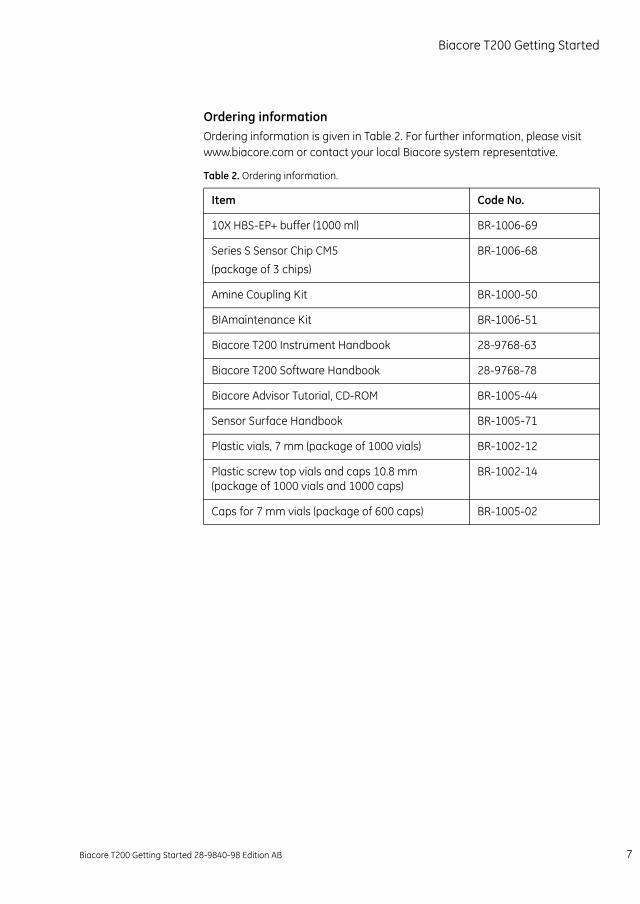
Ordering informationOrdering information is given in Table 2. For further information, please visit www.biacore.com or contact your local Biacore system representative.
Table 2. Ordering information.
Item Code No.
10X HBS-EP+ buffer (1000 ml) BR-1006-69
Series S Sensor Chip CM5
(package of 3 chips)
BR-1006-68
Amine Coupling Kit BR-1000-50
BIAmaintenance Kit BR-1006-51
Biacore T200 Instrument Handbook 28-9768-63
Biacore T200 Software Handbook 28-9768-78
Biacore Advisor Tutorial, CD-ROM BR-1005-44
Sensor Surface Handbook BR-1005-71
Plastic vials, 7 mm (package of 1000 vials) BR-1002-12
Plastic screw top vials and caps 10.8 mm (package of 1000 vials and 1000 caps)
BR-1002-14
Caps for 7 mm vials (package of 600 caps) BR-1005-02
Biacore T200 Getting Started 28-9840-98 Edition AB 7

Biacore T200 Getting StartedIntroduction
8 Biacore T200 Getting Started 28-9840-98 Edition AB
Background information
Background information
This chapter is intended to provide the basis for a more detailed understanding of the main steps in a Biacore assay. The information goes beyond what is explicitly covered in the exercises and is, therefore, a complement to the exercises.
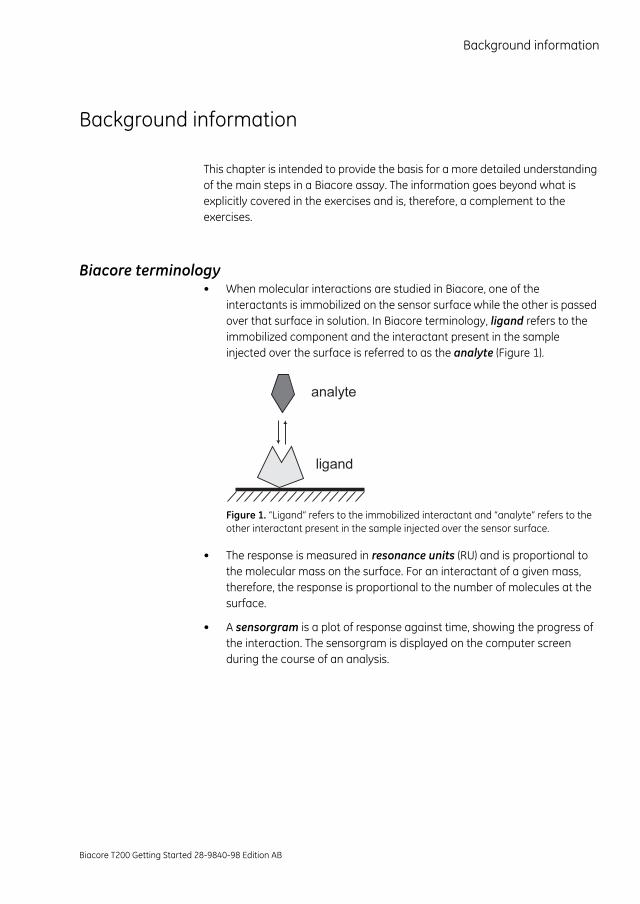
Biacore terminology• When molecular interactions are studied in Biacore, one of the
interactants is immobilized on the sensor surface while the other is passed over that surface in solution. In Biacore terminology, ligand refers to the immobilized component and the interactant present in the sample injected over the surface is referred to as the analyte (Figure 1).
Figure 1. “Ligand” refers to the immobilized interactant and “analyte” refers to the other interactant present in the sample injected over the sensor surface.
• The response is measured in resonance units (RU) and is proportional to the molecular mass on the surface. For an interactant of a given mass, therefore, the response is proportional to the number of molecules at the surface.
• A sensorgram is a plot of response against time, showing the progress of the interaction. The sensorgram is displayed on the computer screen during the course of an analysis.
Biacore T200 Getting Started 28-9840-98 Edition AB 9
Background informationSensor surface properties
There are three major steps in a Biacore assay. These are:
1 Immobilization: The process by which the ligand is attached to the sensor chip surface.
2 Interaction analysis: The analyte is injected over the sensor chip surface and the interaction between the analyte and the immobilized ligand is monitored.
3 Regeneration: The process of removing bound analyte from the ligand on the surface.
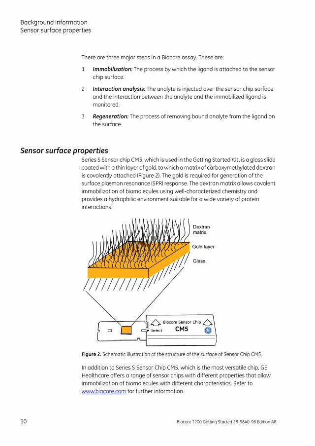
Sensor surface propertiesSeries S Sensor chip CM5, which is used in the Getting Started Kit, is a glass slide coated with a thin layer of gold, to which a matrix of carboxymethylated dextran is covalently attached (Figure 2). The gold is required for generation of the surface plasmon resonance (SPR) response. The dextran matrix allows covalent immobilization of biomolecules using well-characterized chemistry and provides a hydrophilic environment suitable for a wide variety of protein interactions.
Figure 2. Schematic illustration of the structure of the surface of Sensor Chip CM5.
In addition to Series S Sensor Chip CM5, which is the most versatile chip, GE Healthcare offers a range of sensor chips with different properties that allow immobilization of biomolecules with different characteristics. Refer to www.biacore.com for further information.
10 Biacore T200 Getting Started 28-9840-98 Edition AB
Background information
ImmobilizationThere are different ways of immobilizing substances to the sensor surface. The choice of immobilization method depends on the properties of the substance. The immobilization approaches may be directed towards amine, carboxyl, thiol or hydroxyl groups on the ligand, or may use specific tags introduced into the ligand.
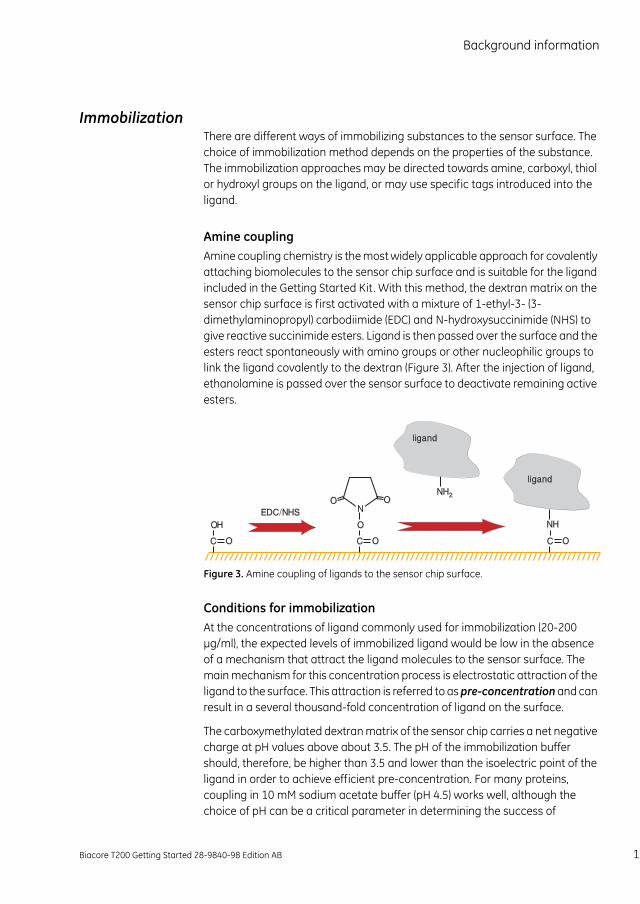
Amine couplingAmine coupling chemistry is the most widely applicable approach for covalently attaching biomolecules to the sensor chip surface and is suitable for the ligand included in the Getting Started Kit. With this method, the dextran matrix on the sensor chip surface is first activated with a mixture of 1-ethyl-3- (3-dimethylaminopropyl) carbodiimide (EDC) and N-hydroxysuccinimide (NHS) to give reactive succinimide esters. Ligand is then passed over the surface and the esters react spontaneously with amino groups or other nucleophilic groups to link the ligand covalently to the dextran (Figure 3). After the injection of ligand, ethanolamine is passed over the sensor surface to deactivate remaining active esters.
Figure 3. Amine coupling of ligands to the sensor chip surface.
Conditions for immobilizationAt the concentrations of ligand commonly used for immobilization (20-200 µg/ml), the expected levels of immobilized ligand would be low in the absence of a mechanism that attract the ligand molecules to the sensor surface. The main mechanism for this concentration process is electrostatic attraction of the ligand to the surface. This attraction is referred to as pre-concentration and can result in a several thousand-fold concentration of ligand on the surface.
The carboxymethylated dextran matrix of the sensor chip carries a net negative charge at pH values above about 3.5. The pH of the immobilization buffer should, therefore, be higher than 3.5 and lower than the isoelectric point of the ligand in order to achieve efficient pre-concentration. For many proteins, coupling in 10 mM sodium acetate buffer (pH 4.5) works well, although the choice of pH can be a critical parameter in determining the success of
Biacore T200 Getting Started 28-9840-98 Edition AB 11
Background informationImmobilization
immobilization in some cases. If you have to use other conditions, bear the following considerations in mind:
• The ionic strength should be low (10 mM monovalent cations recommended) for the electrostatic attraction to occur.
• Buffer components containing primary amine groups and other strong nucleophilic groups (e.g. Tris or sodium azide) must be avoided for amine coupling, as these will compete with the ligand for active esters on the sensor chip surface.
Many proteins show limited stability in low ionic strength solutions and at low pH. The ligand solutions should, therefore, be prepared directly before use.
Example of immobilization pH-scoutingThe experimental procedure of finding the appropriate immobilization pH is referred to as pH-scouting. The example below shows how to set up an immobilization pH-scouting and how to assess the results.
Example 1
In this example, the ligand immobilized was the monoclonal anti-2-microglobulin antibody included in the Getting Started Kit. The ligand was diluted in sodium acetate buffers with different pH (pH 5.5, pH 5.0, pH 4.5 and pH 4.0) to a final concentration of 30 µg/ml in each sample. The flow rate was 10 µl/min and the contact time was two minutes. If your sample availability is restricted and you have to minimize ligand consumption, the flow rate may be set to 5 µl/min and/or a lower ligand concentration may be used.
After the last ligand injection, a wash solution was injected to remove any remaining ligand molecules. A short pulse of 1 M ethanolamine-HCl pH 8.5 (included in the Amine Coupling Kit) or 50 mM NaOH is commonly used for washing surfaces that have been used for pre-concentration/pH-scouting experiments.
12 Biacore T200 Getting Started 28-9840-98 Edition AB
Background information
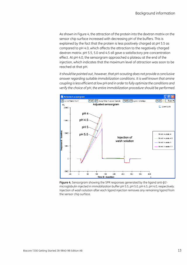
As shown in Figure 4, the attraction of the protein into the dextran matrix on the sensor chip surface increased with decreasing pH of the buffers. This is explained by the fact that the protein is less positively charged at pH 5.5 as compared to pH 4.0, which affects the attraction to the negatively charged dextran matrix. pH 5.5, 5.0 and 4.5 all gave a satisfactory pre-concentration effect. At pH 4.0, the sensorgram approached a plateau at the end of the injection, which indicates that the maximum level of attraction was soon to be reached at that pH.
It should be pointed out, however, that pH-scouting does not provide a conclusive answer regarding suitable immobilization conditions. It is well known that amine coupling is less efficient at low pH and in order to fully optimize the conditions and verify the choice of pH, the entire immobilization procedure should be performed.
Figure 4. Sensorgram showing the SPR responses generated by the ligand anti-2-microglobulin injected in immobilization buffer pH 5.5, pH 5.0, pH 4.5, pH 4.0, respectively. Injection of wash solution after each ligand injection removes any remaining ligand from the sensor chip surface.
Biacore T200 Getting Started 28-9840-98 Edition AB 13
Background informationImmobilization
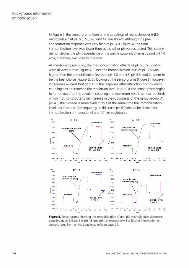
In Figure 5, the sensorgrams from amine couplings of monoclonal anti-2-microglobulin at pH 5.5, 5.0, 4.5 and 4.0 are shown. Although the pre-concentration response was very high at pH 4.0 (Figure 4), the final immobilization level was lower than at the other pH values tested. This clearly demonstrates the pH-dependence of the amine coupling chemistry and pH 4.0 was, therefore, excluded in this case.
As mentioned previously, the pre-concentration effects at pH 5.5, 5.0 and 4.5 were all acceptable (Figure 4). Since the immobilization level at pH 5.5 was higher than the immobilization levels at pH 5.0 and 4.5, pH 5.5 could appear to be the best choice (Figure 5). By looking at the sensorgrams (Figure 5), however, it becomes evident that at pH 5.5 the response after attraction and covalent coupling has not reached the maximum level. At pH 5.0, the sensorgram begins to flatten out after the covalent coupling (the maximum level is almost reached), which may contribute to an increase in the robustness of the assay set-up. At pH 4.5, the plateau is more evident, but at the same time the immobilization level has dropped. Consequently, in this case pH 5.0 should be chosen for immobilization of monoclonal anti-2-microglobulin.
Figure 5. Sensorgrams showing the immobilization of anti-2-microglobulin via amine coupling at pH 5.5, pH 5.0, pH 4.5 and pH 4.0, respectively. For further information on sensorgrams from amine couplings, refer to page 37.
14 Biacore T200 Getting Started 28-9840-98 Edition AB
Background information
Immobilization levelsThe binding capacity of the surface will depend on the levels of immobilized ligand. The term maximum response (Rmax) is often used in connection with Biacore experiments and describes the binding capacity of the surface in terms of the response at saturation. A theoretical Rmax value can be calculated using the formula below:
A theoretically calculated Rmax is often higher than the experimentally derived Rmax for the same interaction. There are many potential explanations for this, such as that the ligand is not fully active or that there is steric hindrance of the interaction, for example.
Different applications may require different binding capacities. A low Rmax, for example, is often beneficial in kinetic analyses, while higher levels are advantageous in concentration measurements.
Ligand requirementsThe quality and purity of the ligand have an important effect on determining the specificity and analyte binding capacity of the surface. The ligand should be as specific as possible for the analyte as the selectivity of the assay is determined by specificity. If necessary, an enhancement molecule can be used to increase the sensitivity and/or specificity of the assay.
The purity of the ligand is of vital importance for the experimental results. Impurities may be immobilized on the sensor chip and could affect the analyte binding capacity of the surface. Sensor surfaces immobilized with impure ligand solutions may give rise to results that are difficult to interpret. The recommendation is, therefore, to use as pure ligand solutions as possible.
Cross-reactivity (i.e. binding of analyte-related molecules to the ligand) and non-specific binding (i.e. general binding to the ligand) are other factors, which can be controlled through the choice of ligand. Note that these factors are generally applicable to the vast majority of immunoassay formats and are not specific to Biacore assays.
Rmaxanalyte MWligand MW------------------------------ immobilized amount stoichiometric ratio=
Biacore T200 Getting Started 28-9840-98 Edition AB 15
Background informationInteraction analysis
Interaction analysisDuring injection of the analyte, the binding of analyte to ligand takes place and is monitored in real time on the screen. After the analyte injection, when buffer flows over the surface, the dissociation of the analyte/ligand complex is monitored. Although analytes in crude sample matrices can be measured and the need for sample purification is low, a few guidelines on sample requirements are given below.
Sample requirementsThe detection principle in Biacore technology measures changes in refractive index (RI) that are related to changes in mass close to the sensor surface. The design of the opto-interface allows for measurements of samples in crude environments, such as serum and cell culture supernatants.
Sample environments that differ greatly from the running buffer will give rise to a bulk refractive index (RI) effect that is commonly present during an injection. Bulk refractive index effects do not affect the binding. Our recommendation is, however, that the samples should be diluted in running buffer to minimize bulk shifts.
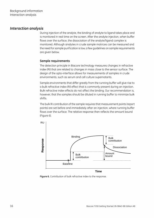
The bulk RI contribution of the sample requires that measurement points (report points) are set before and immediately after an injection, where running buffer flows over the surface. The relative response then reflects the amount bound (Figure 6).
Figure 6. Contribution of bulk refractive index to the response.
Bulkcontribution
RU
Time
Bulkcontribution
Binding
Dissociation
Amountbound
Baseline
16 Biacore T200 Getting Started 28-9840-98 Edition AB
Background information
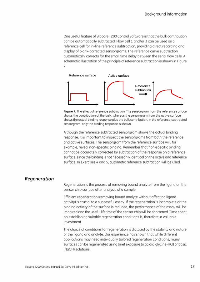
One useful feature of Biacore T200 Control Software is that the bulk contribution can be automatically subtracted. Flow cell 1 and/or 3 can be used as a reference cell for in-line reference subtraction, providing direct recording and display of blank-corrected sensorgrams. The reference curve subtraction automatically corrects for the small time delay between the serial flow cells. A schematic illustration of the principle of reference subtraction is shown in Figure 7.
Figure 7. The effect of reference subtraction. The sensorgram from the reference surface shows the contribution of the bulk, whereas the sensorgram from the active surface shows the actual binding response plus the bulk contribution. In the reference-subtracted sensorgram, only the binding response is shown.
Although the reference subtracted sensorgram shows the actual binding response, it is important to inspect the sensorgrams from both the reference and active surfaces. The sensorgram from the reference surface will, for example, reveal non-specific binding. Remember that non-specific binding cannot be accurately corrected by subtraction of the response on a reference surface, since the binding is not necessarily identical on the active and reference surface. In Exercises 4 and 5, automatic reference subtraction will be used.
RegenerationRegeneration is the process of removing bound analyte from the ligand on the sensor chip surface after analysis of a sample.
Efficient regeneration (removing bound analyte without affecting ligand activity) is crucial to a successful assay. If the regeneration is incomplete or the binding activity of the surface is reduced, the performance of the assay will be impaired and the useful lifetime of the sensor chip will be shortened. Time spent on establishing suitable regeneration conditions is, therefore, a valuable investment.
The choice of conditions for regeneration is dictated by the stability and nature of the ligand and analyte. Our experience has shown that while different applications may need individually tailored regeneration conditions, many surfaces can be regenerated using brief exposure to acidic (glycine-HCl) or basic (NaOH) solutions.
Biacore T200 Getting Started 28-9840-98 Edition AB 17
Background informationRegeneration
If the sensor surface is not efficiently regenerated with high or low pH (either because the analyte is not fully removed or because the ligand loses activity), other conditions may be tested alone or in combination with high or low pH. These include:
• Up to 100% ethylene glycol
• High ionic strength (e.g. 5 M NaCl or 4 M MgCl2)
• Low concentrations of SDS ( 0.5%)
Testing regeneration conditionsWhen exploring appropriate regeneration conditions, it is important to test an interval of different conditions, such as pH or ion concentrations, for example. Our recommendation is to use mild conditions first and then increase the harshness of the treatment progressively until suitable conditions are established. In this way, the risk of damaging the ligand on the sensor surface is minimized.
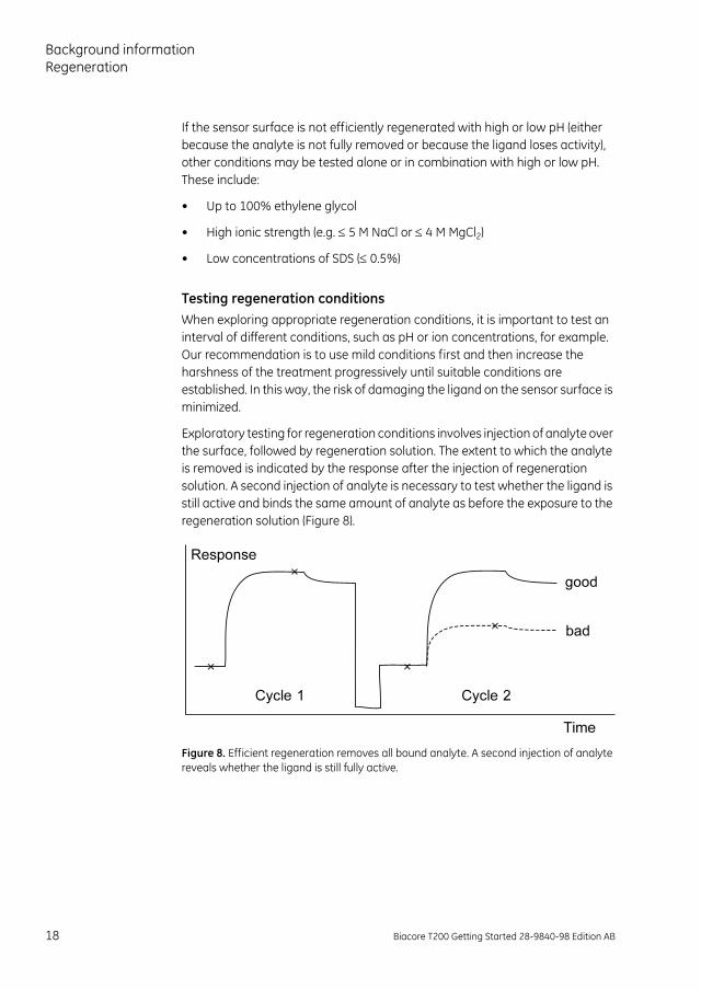
Exploratory testing for regeneration conditions involves injection of analyte over the surface, followed by regeneration solution. The extent to which the analyte is removed is indicated by the response after the injection of regeneration solution. A second injection of analyte is necessary to test whether the ligand is still active and binds the same amount of analyte as before the exposure to the regeneration solution (Figure 8).
Figure 8. Efficient regeneration removes all bound analyte. A second injection of analyte reveals whether the ligand is still fully active.
18 Biacore T200 Getting Started 28-9840-98 Edition AB
Background information
Injection of regeneration solution often gives a considerable bulk response because the refractive index of the regeneration solution is not matched with the running buffer. The relative bulk response may be either positive or negative depending on the solution used.
The analyte injections described above may be used when you want to establish whether a particular regeneration strategy is worth pursuing. To establish regeneration conditions reliably and reveal trends in regeneration efficiency and ligand activity, it is necessary to perform a series of repeated cycles of analyte injection and regeneration. At least five cycles of analyte binding and regeneration are recommended in testing new regeneration conditions. This regeneration scouting procedure is supported in the Regeneration Scouting Wizard in the T200 Control Software. Once the conditions have been found, more extensive tests may be performed to establish that the assay is stable through large numbers of repeated cycles.
General guidance on how to interpret the trends in analyte binding response and baseline response is given below:
• Ideal regeneration: The analyte response is constant after repeated injections and within ±10% of the level reached in the first injection.
• Too mild conditions: The analyte response decreases and the baseline response increases. The decrease in analyte response results from incomplete removal of the analyte from the surface so that the baseline increases. Test one step harsher conditions or change the type of regeneration solution.
• Too harsh conditions: The analyte response decreases and the baseline response is constant or decreases. The drop in analyte response without a corresponding increase in baseline response indicates that the surface is losing analyte-binding capacity. Change the type of regeneration solution. You may have to prepare a new surface if the ligand has been too extensively damaged.
Biacore T200 Getting Started 28-9840-98 Edition AB 19
Background informationRegeneration
Choice of regeneration conditions
Example 2
In this example, regeneration solutions with different pH were tested. Each cycle consisted of an injection of analyte followed by a single injection of regeneration solution. Each regeneration solution was tested for five identical cycles.
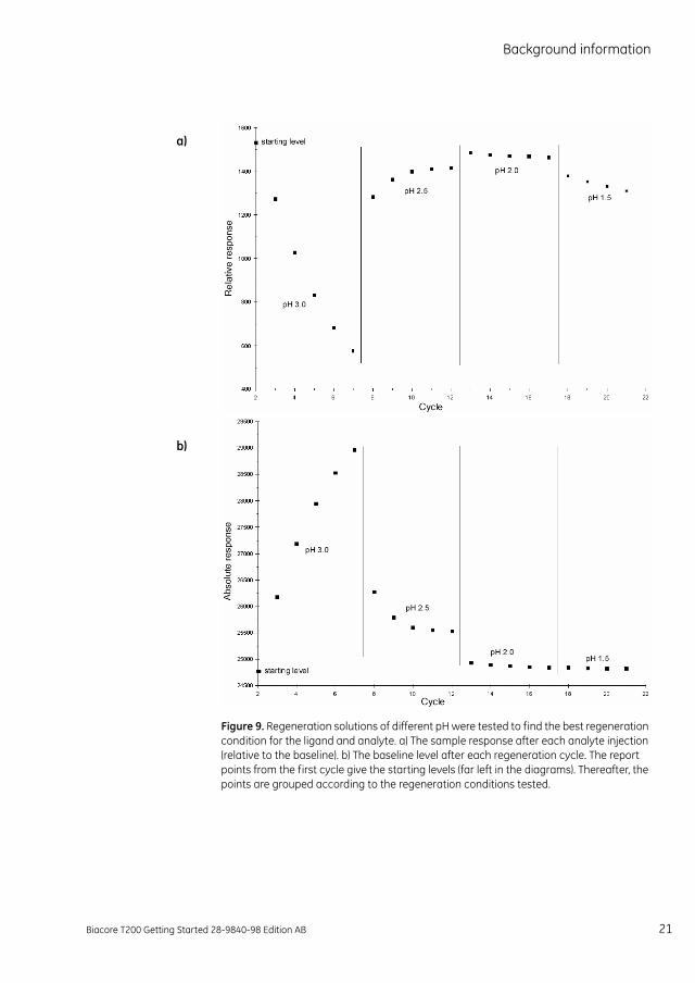
As is shown in Figure 9, at pH 3.0 the analyte binding decreased and the baseline response increased. This suggests that the analyte was not removed from the surface and the binding site on the ligand remained occupied. Consequently, more material accumulated on the surface, allowing less analyte to bind in each cycle. The first condition (pH 3.0) appeared, therefore, to be too mild.
pH 2.5 showed some improvement, but the regeneration was still not good enough, since several cycles were needed to reach a stable sample response. In addition, the baseline was still at a higher level than the starting value.
The third condition (pH 2.0) looks good. Both the sample response and the baseline were close to the starting values after each cycle.
The fourth condition (pH 1.5) was too harsh, since the sample response decreased. The baseline was, however, still acceptable.
The conclusion from this experiment would be to use pH 2.0 as the regeneration solution. The next step would be to test that the surface remains active and is not harmed by this solution during the number of cycles that the assay is intended to cover.
20 Biacore T200 Getting Started 28-9840-98 Edition AB
Background information
Figure 9. Regeneration solutions of different pH were tested to find the best regeneration condition for the ligand and analyte. a) The sample response after each analyte injection (relative to the baseline). b) The baseline level after each regeneration cycle. The report points from the first cycle give the starting levels (far left in the diagrams). Thereafter, the points are grouped according to the regeneration conditions tested.
a)
b)
Biacore T200 Getting Started 28-9840-98 Edition AB 21
Background informationRegeneration
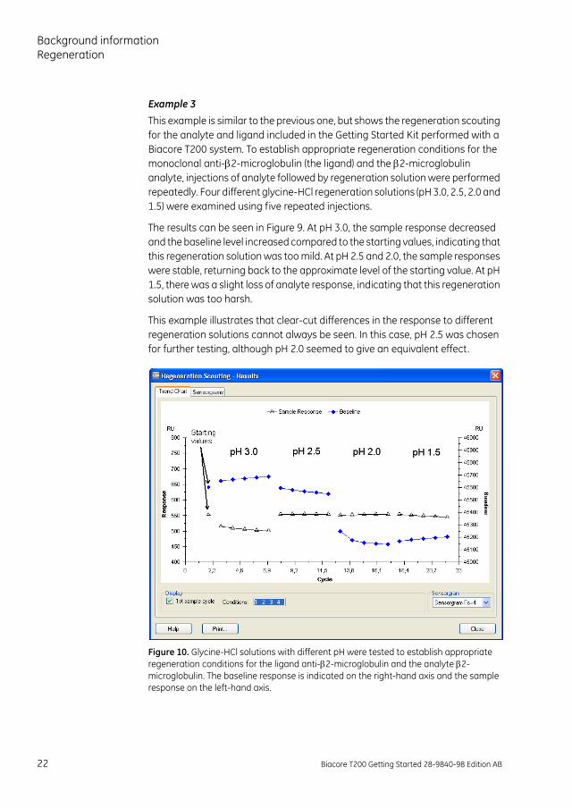
Example 3
This example is similar to the previous one, but shows the regeneration scouting for the analyte and ligand included in the Getting Started Kit performed with a Biacore T200 system. To establish appropriate regeneration conditions for the monoclonal anti-2-microglobulin (the ligand) and the 2-microglobulin analyte, injections of analyte followed by regeneration solution were performed repeatedly. Four different glycine-HCl regeneration solutions (pH 3.0, 2.5, 2.0 and 1.5) were examined using five repeated injections.
The results can be seen in Figure 9. At pH 3.0, the sample response decreased and the baseline level increased compared to the starting values, indicating that this regeneration solution was too mild. At pH 2.5 and 2.0, the sample responses were stable, returning back to the approximate level of the starting value. At pH 1.5, there was a slight loss of analyte response, indicating that this regeneration solution was too harsh.
This example illustrates that clear-cut differences in the response to different regeneration solutions cannot always be seen. In this case, pH 2.5 was chosen for further testing, although pH 2.0 seemed to give an equivalent effect.
Figure 10. Glycine-HCl solutions with different pH were tested to establish appropriate regeneration conditions for the ligand anti-2-microglobulin and the analyte 2-microglobulin. The baseline response is indicated on the right-hand axis and the sample response on the left-hand axis.
22 Biacore T200 Getting Started 28-9840-98 Edition AB
Exercises
Exercises
Description of the experimental set-upThe experiments described in this handbook exploit the binding of 2-microglobulin to immobilized monoclonal anti-2-microglobulin antibodies. The following steps are described:
• Start up of the system.
• The pre-concentration effect: Illustration of the importance of the ion strength and pH of the buffer used for immobilization.
• Immobilization of monoclonal anti-2-microglobulin via amine coupling.
• Interaction analysis: Injection of two different concentrations of 2-microglobulin and evaluation of the results.
• Multiple binding: Injection of an enhancement molecule to amplify the signal from a low concentration of analyte.
• Maintenance routines.
Upon completion of the Getting Started experiments, you should have a basic understanding of the main steps in a Biacore assay and how to handle the instrument and the software. You should also be ready for incorporation of your own reagents into similar protocols.
Biacore T200 Getting Started 28-9840-98 Edition AB 23
ExercisesExercise 1. Start up
Exercise 1. Start upThis section deals with starting up the system, setting up the liquids required for the run, docking the sensor chip, flushing the liquid system and normalizing the signal response. The priming procedure flushes the liquid system with running buffer. This should be done when a new sensor chip is inserted and/or the running buffer is changed.
Start the system1 Switch on the Biacore T200 instrument, PC and printer. If the instrument has
been switched off, temperature stabilization of the detection unit will take approximately one hour. Wait until the yellow Temperature lamp on the front panel of the instrument lights steadily.
2 Take out the Getting Started Kit from the refrigerator and equilibrate to room temperature. Dilute the 10X running buffer with ultrapure deionized water (0.22µm filtered): Mix 25 ml of 10X running buffer with 225 ml water in a 250 ml bottle.
3 Start Biacore T200 Control Software: click on the Start menu and select Biacore T200 Control Software from the Biacore menu. The software establishes connection with the instrument, which takes about 30 seconds.
Insert a sensor chip and prime with buffer4 Place the bottle containing running buffer (prepared in step 2) on the buffer
tray (on the left hand side of the instrument). Insert the tube marked A through the septum in the cap, into the bottom of the bottle. Place unused buffer tubing (B, C and D) in the holder inside the pump compartment door on the left hand side of the instrument.
5 Place a 2-liter bottle for waste solution on the waste and water tray on the right hand side of the instrument. Fit the cap carrying the waste tubes on to the bottle.
Note: Do not use a smaller bottle for waste.
6 Fill a 500 ml bottle with ultrapure water. Fit a cap with septum on to the bottle and place it on the waste and water tray. Insert the tube for water into the bottle.
24 Biacore T200 Getting Started 28-9840-98 Edition AB
Exercises
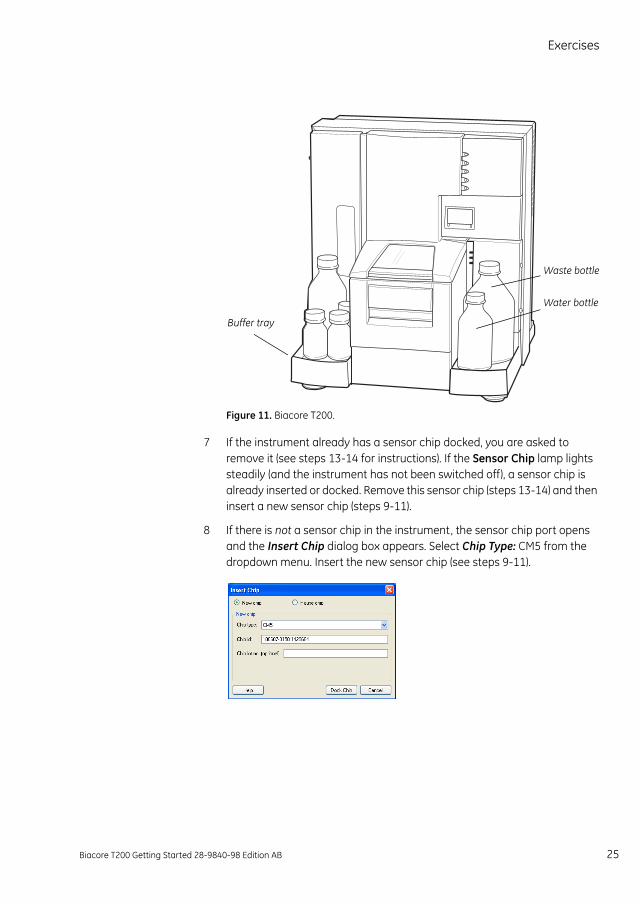
Figure 11. Biacore T200.
7 If the instrument already has a sensor chip docked, you are asked to remove it (see steps 13-14 for instructions). If the Sensor Chip lamp lights steadily (and the instrument has not been switched off), a sensor chip is already inserted or docked. Remove this sensor chip (steps 13-14) and then insert a new sensor chip (steps 9-11).
8 If there is not a sensor chip in the instrument, the sensor chip port opens and the Insert Chip dialog box appears. Select Chip Type: CM5 from the dropdown menu. Insert the new sensor chip (see steps 9-11).
Buffer tray
Waste bottle
Water bottle
Biacore T200 Getting Started 28-9840-98 Edition AB 25
ExercisesExercise 1. Start up
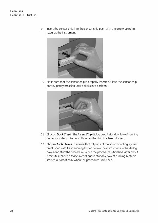
9 Insert the sensor chip into the sensor chip port, with the arrow pointing towards the instrument
10 Make sure that the sensor chip is properly inserted. Close the sensor chip port by gently pressing until it clicks into position.
11 Click on Dock Chip in the Insert Chip dialog box. A standby flow of running buffer is started automatically when the chip has been docked.
12 Choose Tools: Prime to ensure that all parts of the liquid handling system are flushed with fresh running buffer. Follow the instructions in the dialog boxes and start the procedure. When the procedure is finished (after about 7 minutes), click on Close. A continuous standby flow of running buffer is started automatically when the procedure is finished.
26 Biacore T200 Getting Started 28-9840-98 Edition AB
Exercises
Removing a sensor chip13 If a sensor chip is docked (and the instrument has not been switched off), a
Running Standby is visible in the status window at the bottom of the screen. Choose Tools: Stop Standby to stop the continuous buffer flow.
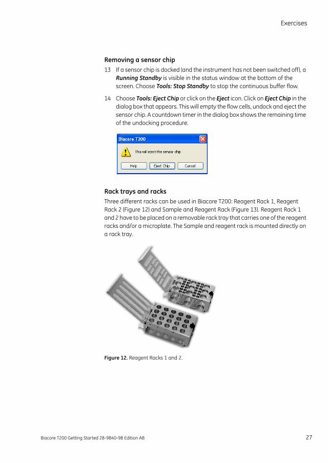
14 Choose Tools: Eject Chip or click on the Eject icon. Click on Eject Chip in the dialog box that appears. This will empty the flow cells, undock and eject the sensor chip. A countdown timer in the dialog box shows the remaining time of the undocking procedure.
Rack trays and racksThree different racks can be used in Biacore T200: Reagent Rack 1, Reagent Rack 2 (Figure 12) and Sample and Reagent Rack (Figure 13). Reagent Rack 1 and 2 have to be placed on a removable rack tray that carries one of the reagent racks and/or a microplate. The Sample and reagent rack is mounted directly on a rack tray.
Figure 12. Reagent Racks 1 and 2.
Biacore T200 Getting Started 28-9840-98 Edition AB 27
ExercisesExercise 1. Start up
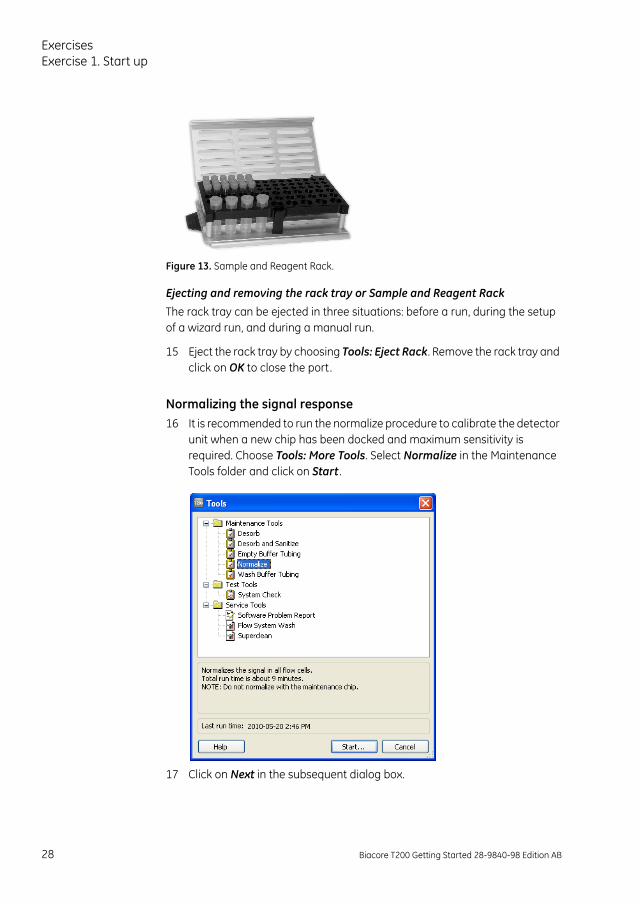
Figure 13. Sample and Reagent Rack.
Ejecting and removing the rack tray or Sample and Reagent Rack
The rack tray can be ejected in three situations: before a run, during the setup of a wizard run, and during a manual run.
15 Eject the rack tray by choosing Tools: Eject Rack. Remove the rack tray and click on OK to close the port.
Normalizing the signal response16 It is recommended to run the normalize procedure to calibrate the detector
unit when a new chip has been docked and maximum sensitivity is required. Choose Tools: More Tools. Select Normalize in the Maintenance Tools folder and click on Start .
17 Click on Next in the subsequent dialog box.
28 Biacore T200 Getting Started 28-9840-98 Edition AB
Exercises
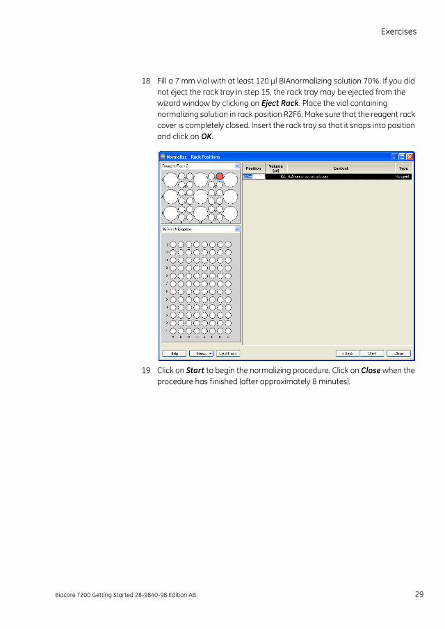
18 Fill a 7 mm vial with at least 120 µl BIAnormalizing solution 70%. If you did not eject the rack tray in step 15, the rack tray may be ejected from the wizard window by clicking on Eject Rack. Place the vial containing normalizing solution in rack position R2F6. Make sure that the reagent rack cover is completely closed. Insert the rack tray so that it snaps into position and click on OK.
19 Click on Start to begin the normalizing procedure. Click on Close when the procedure has finished (after approximately 8 minutes).
Biacore T200 Getting Started 28-9840-98 Edition AB 29
ExercisesExercise 2. Effect of buffer on pre-concentration
Exercise 2. Effect of buffer on pre-concentrationIn this exercise, the importance of using a buffer with appropriate pH and ionic strength to obtain sufficient pre-concentration is demonstrated. The injections are performed by using the manual injection mode of the instrument. The data collection is started and the injection commands are entered manually. Manual operation is convenient during method development when the result of one injection may guide the next experiment. It can also be used in control experiments, such as injection of sample over an unmodified sensor chip surface.
1 Make sure that no liquid is condensed in the ligand tube as this may affect the ligand concentration. If needed, spin the tube before diluting the ligand.
2 Make dilutions of the ligand in both HBS-EP+ (running buffer) and immobilization buffer (10 mM sodium acetate, pH 5.0). Use 7 mm plastic vials and cap all vials. In separate vials, mix 3 µl ligand stock solution with 97 µl HBS-EP+ and 3 µl ligand with 97 µl sodium acetate buffer. Prepare a vial containing 500 µl 10 mM glycine-HCl, pH 2.5 (for regeneration). This vial will also be used in exercises 4 and 5.
3 Choose Run: Manual Run.
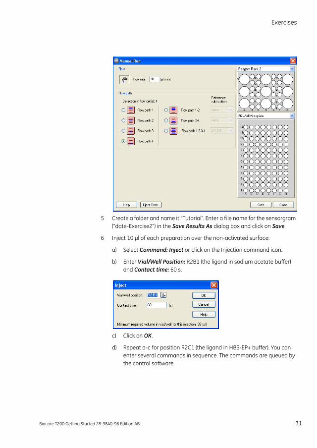
4 Enter Flow rate: 10 µl/min and choose detection in flow cell 4 by ticking Flow path 4 in the Manual Run dialog box. Click on Eject rack. Place the ligand diluted in acetate buffer in rack position R2B1, the ligand diluted in HBS-EP+ buffer in rack position R2C1 and the vial containing glycine-HCl in rack position R2E1. Make sure that the reagent rack cover is completely closed. If the sample compartment has closed before you are ready to insert the rack tray, click on Eject rack again to eject the rack tray carriage. Insert the rack tray, click on OK and then click on Start .
30 Biacore T200 Getting Started 28-9840-98 Edition AB
Exercises
5 Create a folder and name it “Tutorial”. Enter a file name for the sensorgram (“date-Exercise2”) in the Save Results As dialog box and click on Save.
6 Inject 10 µl of each preparation over the non-activated surface:
a) Select Command: Inject or click on the Injection command icon.
b) Enter Vial/Well Position: R2B1 (the ligand in sodium acetate buffer) and Contact time: 60 s.
c) Click on OK.
d) Repeat a-c for position R2C1 (the ligand in HBS-EP+ buffer). You can enter several commands in sequence. The commands are queued by the control software.
Biacore T200 Getting Started 28-9840-98 Edition AB 31
ExercisesExercise 2. Effect of buffer on pre-concentration
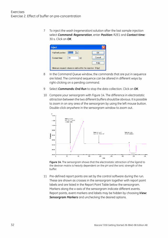
7 To inject the wash (regeneration) solution after the last sample injection select Command: Regeneration, enter Position: R2E1 and Contact time: 30 s. Click on OK.
8 In the Command Queue window, the commands that are put in sequence are listed. The command sequence can be altered in different ways by right-clicking on a pending command.
9 Select Commands: End Run to stop the data collection. Click on OK.
10 Compare your sensorgram with Figure 14. The difference in electrostatic attraction between the two different buffers should be obvious. It is possible to zoom in on any area of the sensorgram by using the left mouse button. Double-click anywhere in the sensorgram window to zoom out.
Figure 14. The sensorgram shows that the electrostatic attraction of the ligand to the dextran matrix is heavily dependent on the pH and the ionic strength of the buffer.
11 Pre-defined report points are set by the control software during the run. These are shown as crosses in the sensorgram together with report point labels and are listed in the Report Point Table below the sensorgram. Markers along the x-axis of the sensorgram indicate different events. Report points, event markers and labels may be hidden by choosing View: Sensorgram Markers and unchecking the desired options.
32 Biacore T200 Getting Started 28-9840-98 Edition AB
Exercises
12 To quantify the response level, you first have to define a baseline. Zoom in on the area just before the injection of ligand diluted in sodium acetate buffer. Select View: Reference Line to activate the reference line. Drag the reference line to a point 10-20 s before the injection start. Select View: Baseline to display a baseline. This sets the baseline level to zero. The response level (0.0 RU) is now displayed in a window at the top left on the screen.
13 Drag the reference line to a time point at the end of the injection. As you move the reference line along the sensorgram the response level at the different time points can be read in the window at the top left of the screen.
14 Select View: Baseline to remove the baseline and View: Reference Line to remove the reference line.
15 Close the sensorgram window.
ConclusionThis exercise illustrates the importance of the ionic strength and the pH of the buffer on pre-concentration. Dilution of the ligand in HBS-EP+ results in a small pre-concentration effect, while the dilution in 10 mM sodium acetate buffer, pH 5.0, results in a much higher pre-concentration. Consequently, the choice of immobilization buffer has a great impact on the experimental results in this case.
Biacore T200 Getting Started 28-9840-98 Edition AB 33
ExercisesExercise 3. Immobilization
Exercise 3. ImmobilizationIn this exercise, the ligand (monoclonal anti-2-microglobulin) is immobilized on the CM5 sensor chip surface. A wizard guides you through the different steps in setting up an immobilization template. The template can be saved and used to simplify further immobilizations.
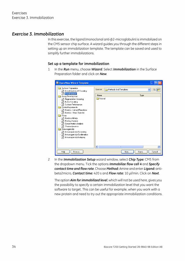
Set up a template for immobilization1 In the Run menu, choose Wizard. Select Immobilization in the Surface
Preparation folder and click on New.
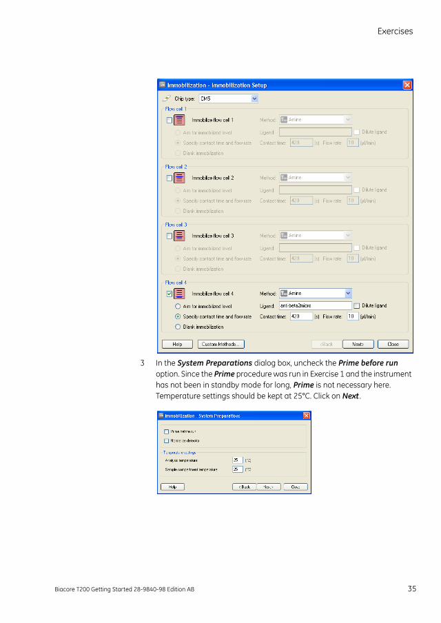
2 In the Immobilization Setup wizard window, select Chip Type: CM5 from the dropdown menu. Tick the options Immobilize flow cell 4 and Specify contact time and flow rate. Choose Method: Amine and enter Ligand: anti-beta2micro, Contact time: 420 s and Flow rate: 10 µl/min. Click on Next .
The option Aim for immobilized level, which will not be used here, gives you the possibility to specify a certain immobilization level that you want the software to target. This can be useful for example, when you work with a new protein and need to try out the appropriate immobilization conditions.
34 Biacore T200 Getting Started 28-9840-98 Edition AB
Exercises
3 In the System Preparations dialog box, uncheck the Prime before run option. Since the Prime procedure was run in Exercise 1 and the instrument has not been in standby mode for long, Prime is not necessary here. Temperature settings should be kept at 25°C. Click on Next .
Biacore T200 Getting Started 28-9840-98 Edition AB 35
ExercisesExercise 3. Immobilization
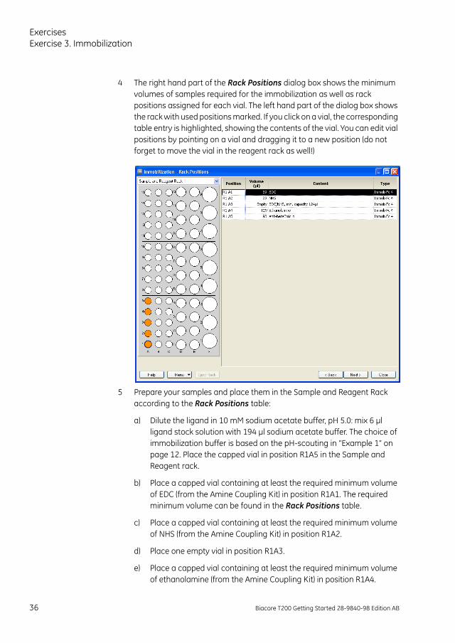
4 The right hand part of the Rack Positions dialog box shows the minimum volumes of samples required for the immobilization as well as rack positions assigned for each vial. The left hand part of the dialog box shows the rack with used positions marked. If you click on a vial, the corresponding table entry is highlighted, showing the contents of the vial. You can edit vial positions by pointing on a vial and dragging it to a new position (do not forget to move the vial in the reagent rack as well!)
5 Prepare your samples and place them in the Sample and Reagent Rack according to the Rack Positions table:
a) Dilute the ligand in 10 mM sodium acetate buffer, pH 5.0: mix 6 µl ligand stock solution with 194 µl sodium acetate buffer. The choice of immobilization buffer is based on the pH-scouting in “Example 1” on page 12. Place the capped vial in position R1A5 in the Sample and Reagent rack.
b) Place a capped vial containing at least the required minimum volume of EDC (from the Amine Coupling Kit) in position R1A1. The required minimum volume can be found in the Rack Positions table.
c) Place a capped vial containing at least the required minimum volume of NHS (from the Amine Coupling Kit) in position R1A2.
d) Place one empty vial in position R1A3.
e) Place a capped vial containing at least the required minimum volume of ethanolamine (from the Amine Coupling Kit) in position R1A4.
36 Biacore T200 Getting Started 28-9840-98 Edition AB
Exercises
6 Make sure that your vials are in the correct rack positions in Sample and reagent rack 1. Close the cover completely.
7 In the wizard window (below the racks), select Menu: Save Wizard Template As. Create a folder and name it “Tutorial”. Enter a file name for the wizard template (“date-Immobilization”) and click on Save.
8 Click on Eject Rack. Take out the rack tray and replace it with Sample and reagent rack 1. Insert the rack so that it snaps into position. Click on OK to insert the rack.
9 Click on Next in the Rack Positions dialog box. The Prepare Run Protocol dialog box displays important assay steps that have to be checked before starting the run. Click on Start to begin the immobilization procedure. Enter a file name for the results: “date-Exercise3” and click on Save. The immobilization will take approximately 30 minutes.
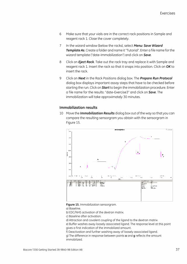
Immobilization results10 Move the Immobilization Results dialog box out of the way so that you can
compare the resulting sensorgram you obtain with the sensorgram in Figure 15.
Figure 15. Immobilization sensorgram.a) Baseline.b) EDC/NHS activation of the dextran matrix.c) Baseline after activation.d) Attraction and covalent coupling of the ligand to the dextran matrixe) Buffer washes away loosely associated ligand. The response level at this point gives a first indication of the immobilized amount.f) Deactivation and further washing away of loosely associated ligand.g) The difference in response between points a and g reflects the amount immobilized.
Biacore T200 Getting Started 28-9840-98 Edition AB 37
ExercisesExercise 3. Immobilization
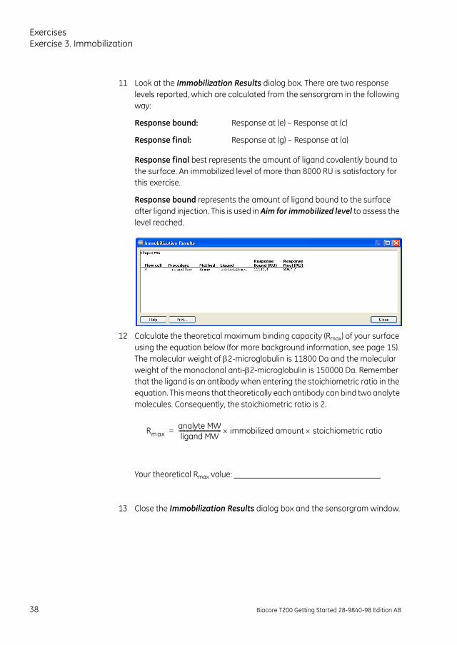
11 Look at the Immobilization Results dialog box. There are two response levels reported, which are calculated from the sensorgram in the following way:
Response final best represents the amount of ligand covalently bound to the surface. An immobilized level of more than 8000 RU is satisfactory for this exercise.
Response bound represents the amount of ligand bound to the surface after ligand injection. This is used in Aim for immobilized level to assess the level reached.
12 Calculate the theoretical maximum binding capacity (Rmax) of your surface using the equation below (for more background information, see page 15). The molecular weight of 2-microglobulin is 11800 Da and the molecular weight of the monoclonal anti-2-microglobulin is 150000 Da. Remember that the ligand is an antibody when entering the stoichiometric ratio in the equation. This means that theoretically each antibody can bind two analyte molecules. Consequently, the stoichiometric ratio is 2.
Your theoretical Rmax value:
13 Close the Immobilization Results dialog box and the sensorgram window.
Response bound:
Response final:
Response at (e) – Response at (c)
Response at (g) – Response at (a)
Rmaxanalyte MWligand MW------------------------------ immobilized amount stoichiometric ratio=
38 Biacore T200 Getting Started 28-9840-98 Edition AB
Exercises
Exercise 4. Interaction analysisIn this exercise, two concentrations of 2-microglobulin are injected over the immobilized anti-2-microglobulin antibody. An application will be set up with the help of the Binding Analysis Wizard.
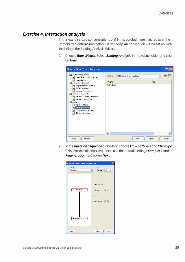
1 Choose Run: Wizard. Select Binding Analysis in the Assay folder and click on New.
2 In the Injection Sequence dialog box, choose Flow path: 4-3 and Chip type: CM5. For the injection sequence, use the default settings Sample: 1 and Regeneration: 1. Click on Next .
Biacore T200 Getting Started 28-9840-98 Edition AB 39
ExercisesExercise 4. Interaction analysis
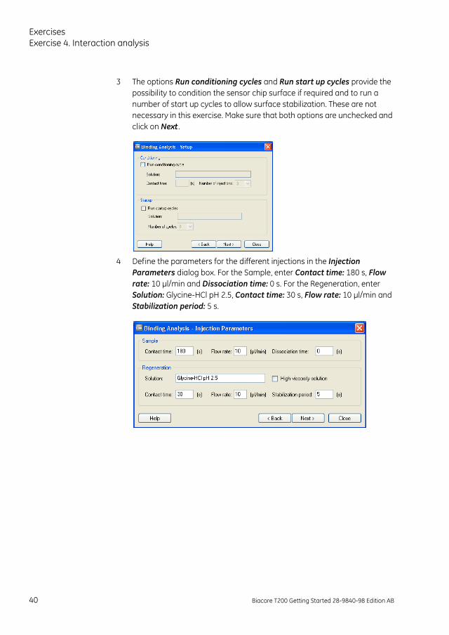
3 The options Run conditioning cycles and Run start up cycles provide the possibility to condition the sensor chip surface if required and to run a number of start up cycles to allow surface stabilization. These are not necessary in this exercise. Make sure that both options are unchecked and click on Next .
4 Define the parameters for the different injections in the Injection Parameters dialog box. For the Sample, enter Contact time: 180 s, Flow rate: 10 µl/min and Dissociation time: 0 s. For the Regeneration, enter Solution: Glycine-HCl pH 2.5, Contact time: 30 s, Flow rate: 10 µl/min and Stabilization period: 5 s.
40 Biacore T200 Getting Started 28-9840-98 Edition AB
Exercises
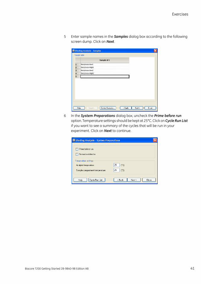
5 Enter sample names in the Samples dialog box according to the following screen dump. Click on Next .
6 In the System Preparations dialog box, uncheck the Prime before run option. Temperature settings should be kept at 25°C. Click on Cycle Run List if you want to see a summary of the cycles that will be run in your experiment. Click on Next to continue.
Biacore T200 Getting Started 28-9840-98 Edition AB 41
ExercisesExercise 4. Interaction analysis
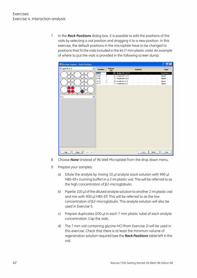
7 In the Rack Positions dialog box, it is possible to edit the positions of the vials by selecting a vial position and dragging it to a new position. In this exercise, the default positions in the microplate have to be changed to positions that fit the vials included in the kit (7 mm plastic vials). An example of where to put the vials is provided in the following screen dump:
8 Choose None (instead of 96 Well Microplate) from the drop down menu.
9 Prepare your samples:
a) Dilute the analyte by mixing 10 µl analyte stock solution with 990 µl HBS-EP+ (running buffer) in a 2 ml plastic vial. This will be referred to as the high concentration of 2-microglobulin.
b) Pipette 100 µl of the diluted analyte solution to another 2 ml plastic vial and mix with 900 µl HBS-EP. This will be referred to as the low concentration of 2-microglobulin. This analyte solution will also be used in Exercise 5.
c) Prepare duplicates (200 µl in each 7 mm plastic tube) of each analyte concentration. Cap the vials.
d) The 7 mm vial containing glycine-HCl (from Exercise 2) will be used in this exercise. Check that there is at least the minimum volume of regeneration solution required (see the Rack Positions table) left in the vial.
42 Biacore T200 Getting Started 28-9840-98 Edition AB
Exercises
10 Place the vials in the positions in Reagent rack 2 that you determined in step 7. Use the table in the Rack Positions dialog box or print a similar table by choosing Print Rack Positions from the drop down Menu on the left-hand side at the bottom of the Rack Positions dialog box. Close the reagent rack cover. Slide the reagent rack into the holder on the rack tray and check that it is correctly oriented.
11 Eject the inserted rack by clicking on Eject Rack. Remove the Sample and reagent rack, and load the rack tray with Reagent rack 2. Click on OK.
12 Save the wizard template by choosing Save Wizard Template As from the drop down Menu. Open the folder “Tutorial” that you created, enter a file name “date-Ex4-Interaction” and click on Save.
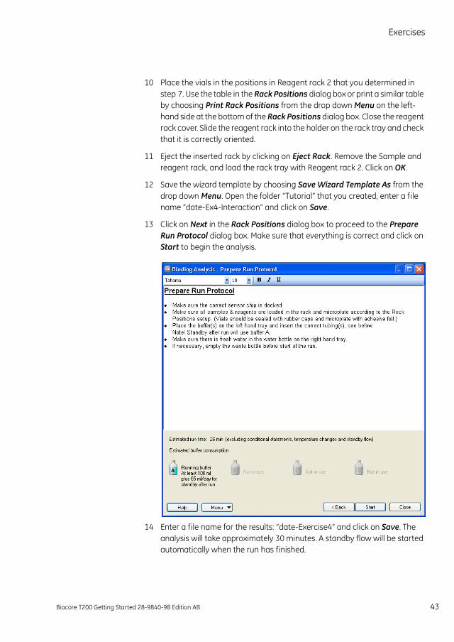
13 Click on Next in the Rack Positions dialog box to proceed to the Prepare Run Protocol dialog box. Make sure that everything is correct and click on Start to begin the analysis.
14 Enter a file name for the results: “date-Exercise4” and click on Save. The analysis will take approximately 30 minutes. A standby flow will be started automatically when the run has finished.
Biacore T200 Getting Started 28-9840-98 Edition AB 43
ExercisesExercise 4. Interaction analysis
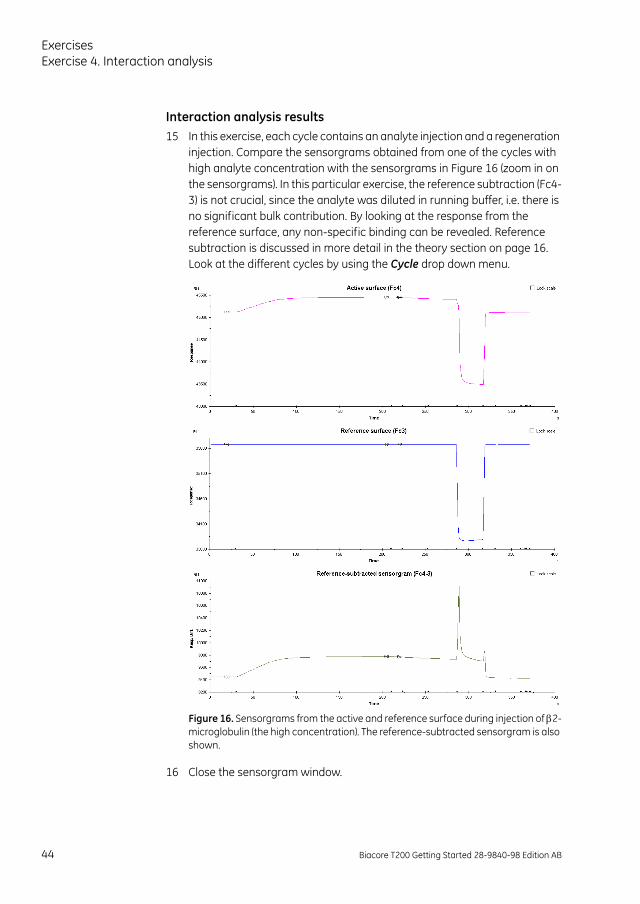
Interaction analysis results15 In this exercise, each cycle contains an analyte injection and a regeneration
injection. Compare the sensorgrams obtained from one of the cycles with high analyte concentration with the sensorgrams in Figure 16 (zoom in on the sensorgrams). In this particular exercise, the reference subtraction (Fc4-3) is not crucial, since the analyte was diluted in running buffer, i.e. there is no significant bulk contribution. By looking at the response from the reference surface, any non-specific binding can be revealed. Reference subtraction is discussed in more detail in the theory section on page 16. Look at the different cycles by using the Cycle drop down menu.
Figure 16. Sensorgrams from the active and reference surface during injection of 2-microglobulin (the high concentration). The reference-subtracted sensorgram is also shown.
16 Close the sensorgram window.
44 Biacore T200 Getting Started 28-9840-98 Edition AB
Exercises
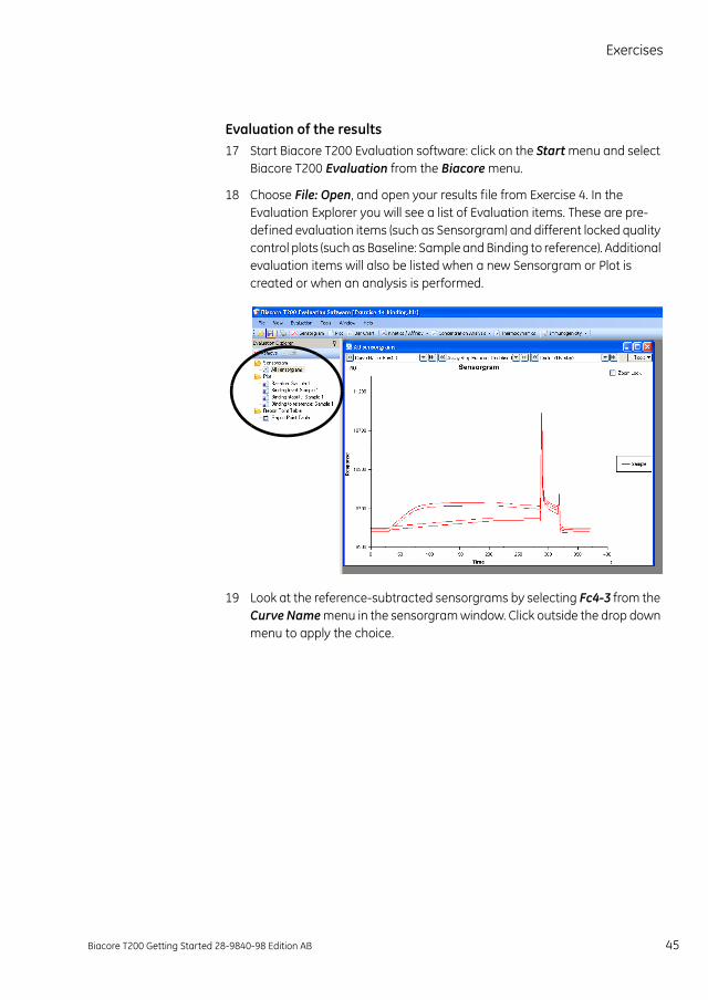
Evaluation of the results17 Start Biacore T200 Evaluation software: click on the Start menu and select
Biacore T200 Evaluation from the Biacore menu.
18 Choose File: Open, and open your results file from Exercise 4. In the Evaluation Explorer you will see a list of Evaluation items. These are pre-defined evaluation items (such as Sensorgram) and different locked quality control plots (such as Baseline: Sample and Binding to reference). Additional evaluation items will also be listed when a new Sensorgram or Plot is created or when an analysis is performed.
19 Look at the reference-subtracted sensorgrams by selecting Fc4-3 from the Curve Name menu in the sensorgram window. Click outside the drop down menu to apply the choice.
Biacore T200 Getting Started 28-9840-98 Edition AB 45
ExercisesExercise 4. Interaction analysis
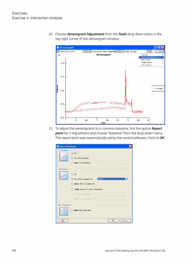
20 Choose Sensorgram Adjustment from the Tools drop down menu in the top right corner of the sensorgram window.
21 To adjust the sensorgrams to a common baseline, tick the option Report point for Y-Adjustment and choose “baseline” from the drop down menu. This report point was automatically set by the control software. Click on OK.
46 Biacore T200 Getting Started 28-9840-98 Edition AB
Exercises
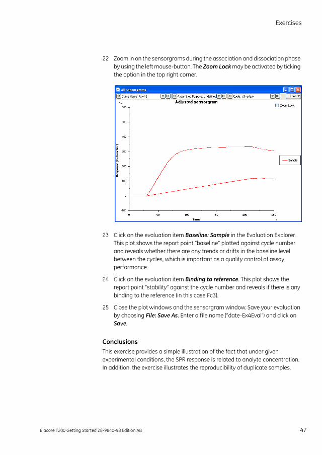
22 Zoom in on the sensorgrams during the association and dissociation phase by using the left mouse-button. The Zoom Lock may be activated by ticking the option in the top right corner.
23 Click on the evaluation item Baseline: Sample in the Evaluation Explorer. This plot shows the report point “baseline” plotted against cycle number and reveals whether there are any trends or drifts in the baseline level between the cycles, which is important as a quality control of assay performance.
24 Click on the evaluation item Binding to reference. This plot shows the report point “stability” against the cycle number and reveals if there is any binding to the reference (in this case Fc3).
25 Close the plot windows and the sensorgram window. Save your evaluation by choosing File: Save As. Enter a file name (“date-Ex4Eval”) and click on Save.
ConclusionsThis exercise provides a simple illustration of the fact that under given experimental conditions, the SPR response is related to analyte concentration. In addition, the exercise illustrates the reproducibility of duplicate samples.
Biacore T200 Getting Started 28-9840-98 Edition AB 47
ExercisesExercise 5. Interaction analysis – multiple binding
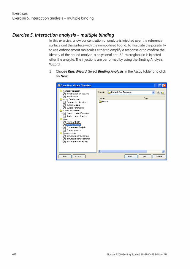
Exercise 5. Interaction analysis – multiple bindingIn this exercise, a low concentration of analyte is injected over the reference surface and the surface with the immobilized ligand. To illustrate the possibility to use enhancement molecules either to amplify a response or to confirm the identity of the bound analyte, a polyclonal anti-2-microglobulin is injected after the analyte. The injections are performed by using the Binding Analysis Wizard.
1 Choose Run: Wizard. Select Binding Analysis in the Assay folder and click on New.
48 Biacore T200 Getting Started 28-9840-98 Edition AB
Exercises
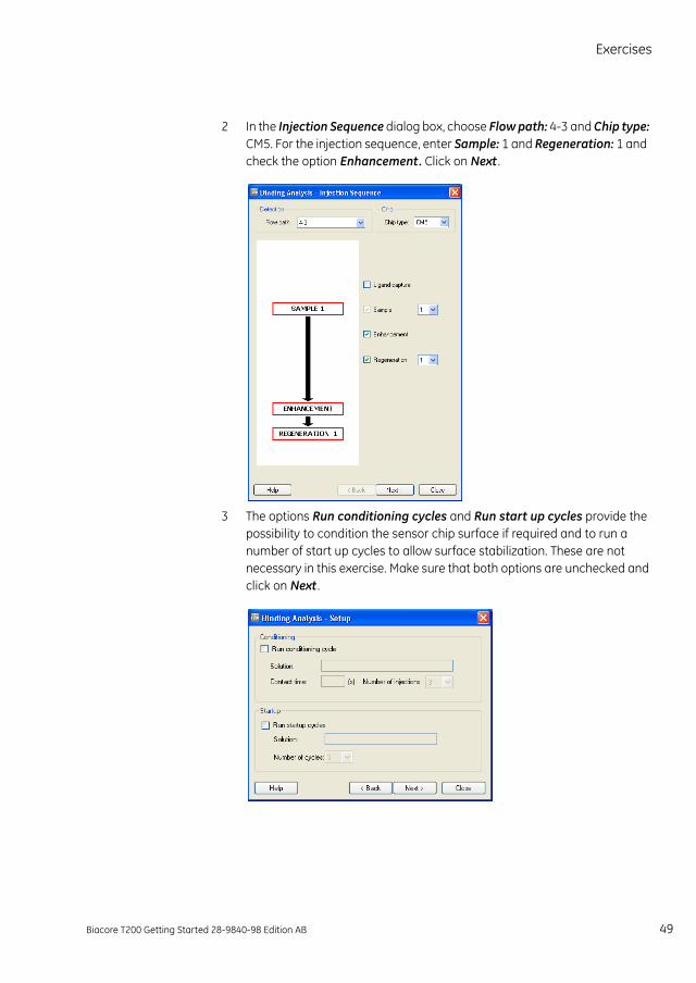
2 In the Injection Sequence dialog box, choose Flow path: 4-3 and Chip type: CM5. For the injection sequence, enter Sample: 1 and Regeneration: 1 and check the option Enhancement. Click on Next .
3 The options Run conditioning cycles and Run start up cycles provide the possibility to condition the sensor chip surface if required and to run a number of start up cycles to allow surface stabilization. These are not necessary in this exercise. Make sure that both options are unchecked and click on Next .
Biacore T200 Getting Started 28-9840-98 Edition AB 49
ExercisesExercise 5. Interaction analysis – multiple binding
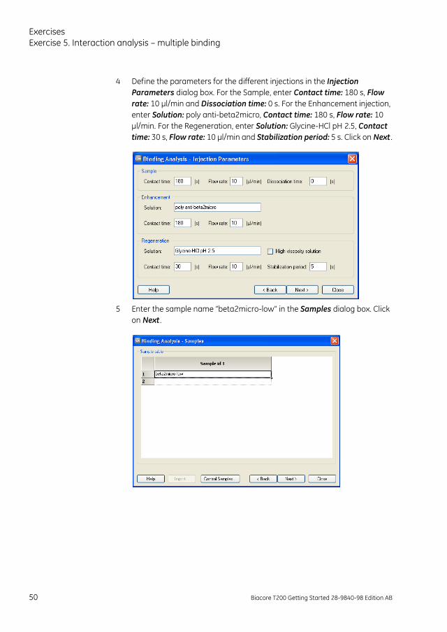
4 Define the parameters for the different injections in the Injection Parameters dialog box. For the Sample, enter Contact time: 180 s, Flow rate: 10 µl/min and Dissociation time: 0 s. For the Enhancement injection, enter Solution: poly anti-beta2micro, Contact time: 180 s, Flow rate: 10 µl/min. For the Regeneration, enter Solution: Glycine-HCl pH 2.5, Contact time: 30 s, Flow rate: 10 µl/min and Stabilization period: 5 s. Click on Next .
5 Enter the sample name “beta2micro-low” in the Samples dialog box. Click on Next .
50 Biacore T200 Getting Started 28-9840-98 Edition AB
Exercises
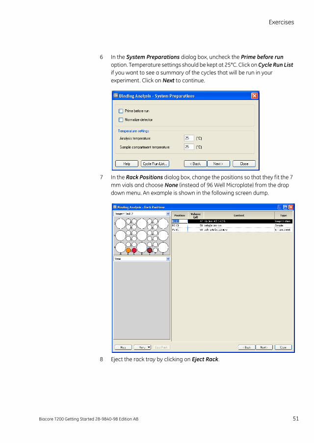
6 In the System Preparations dialog box, uncheck the Prime before run option. Temperature settings should be kept at 25°C. Click on Cycle Run List if you want to see a summary of the cycles that will be run in your experiment. Click on Next to continue.
7 In the Rack Positions dialog box, change the positions so that they fit the 7 mm vials and choose None (instead of 96 Well Microplate) from the drop down menu. An example is shown in the following screen dump.
8 Eject the rack tray by clicking on Eject Rack.
Biacore T200 Getting Started 28-9840-98 Edition AB 51

ExercisesExercise 5. Interaction analysis – multiple binding
9 Prepare your samples:
a) Dilute the polyclonal anti-2-microglobulin by mixing 10 µl antibody stock solution with 990 µl HBS-EP+ (running buffer) in a 2 ml plastic tube. Transfer 100 µl of the diluted antibody to a 7 mm plastic vial and cap it . Place the vial in rack position R2B1.
b) Pipette 100 µl of the “low-concentration” analyte solution from Exercise 4 to a 7 mm plastic vial. Cap the vial and place it in rack position R2C1.
c) The 7 mm vial containing regeneration solution (glycine-HCl, from Exercise 2 and 4) will be used in this exercise. Make sure that the vial is placed in rack position R2E1.
10 Load the rack tray into the instrument and click on OK.
11 Click on Next in the Rack Positions dialog box and proceed to the Prepare Run Protocol dialog box. Make sure that everything is correct and click on Start to begin the analysis.
12 In the Save Wizard Template As dialog box, open the folder “Tutorial”, enter a file name for the wizard template (“date-Exercise5”) and click on Save.
13 Enter a file name for the results (“date-Exercise5”) in the Save Results As dialog box and click on Save.
Multiple binding results14 Compare the resulting sensorgram from Fc4 with that shown in Figure 17.
Figure 17. The sensorgram clearly shows the enhancing effect of the injection of polyclonal anti-2-microglobulin (the enhancement molecule) as compared to the response generated by the injection of the low concentration of analyte.
52 Biacore T200 Getting Started 28-9840-98 Edition AB

Exercises
15 Select the sensorgram in Fc4 by using the Curve drop down menu or clicking on the sensorgram. Select View: Reference Line to activate a reference line. Drag the reference line to a time point somewhere during the first half of the analyte injection in the sensorgram.
16 Add a report point by selecting Edit: Add Report Point . Enter the name “Binding_Early_beta2micro” in the Id field. The response recorded for the report point will be averaged over the time window specified by the Window parameter (use the default value of 5 s). Enter the time at which the report point should be placed (displayed in the Reference line window on the top left of the screen). The baseline option can be checked in order to use the added report point as a baseline for relative responses in other report points. The option Apply to all curves places the report points at the same position on all curves. Click on OK.
17 Drag the reference line to a position just after the injection of the polyclonal anti-2-microglobulin. Add a report point called “Binding_Early_Polyantibeta2” by following the instructions in step 16.
18 The report points are now listed in the results table below the sensorgram. Report points can also be added/edited in Biacore T200 Evaluation Software.
19 Remove the reference line by choosing View: Reference Line.
20 Look at the sensorgram from Fc3 (the reference cell) to determine whether there is any non-specific binding to the dextran matrix.
21 Close the sensorgram window.
ConclusionsIn this exercise, the effect of an enhancement molecule is clearly seen. Enhancement molecules can be used in situations other than the signal amplification illustrated in Exercise 5. It is also possible to enhance the specificity by using a secondary binder. For example, if a ligand binds a family of analyte species, the secondary binder should be able to distinguish between these different analyte species. In addition, secondary binders are commonly used in analyses of different types of multicomponent complexes.
Biacore T200 Getting Started 28-9840-98 Edition AB 53
ExercisesMethods
MethodsBiacore T200 offers three ways of performing analyses. Two of them, Manual run and Wizards are demonstrated in the previous exercises. The third option is to run methods that are defined using the Method Builder. A method can be generated from a wizard template and opened in Method Builder in cases where additional flexibility is needed, or Biacore Methods with pre-defined example settings can be used and modified if necessary. Methods may also be built from scratch in the Method Builder. When you are used to working with the wizards in Biacore T200 Control Software, you can explore the additional flexibility in the Method Builder by creating your own methods. For further information on Method Builder, refer to Biacore T200 Software Handbook.
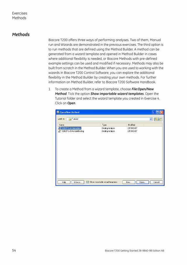
1 To create a Method from a wizard template, choose File:Open/New Method. Tick the option Show importable wizard templates. Open the Tutorial folder and select the wizard template you created in Exercise 4. Click on Open.
54 Biacore T200 Getting Started 28-9840-98 Edition AB
Exercises
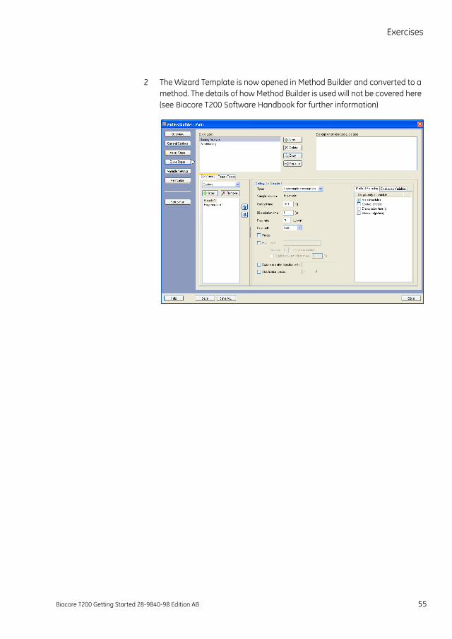
2 The Wizard Template is now opened in Method Builder and converted to a method. The details of how Method Builder is used will not be covered here (see Biacore T200 Software Handbook for further information)
Biacore T200 Getting Started 28-9840-98 Edition AB 55

ExercisesExercise 6. Kinetic analysis
Exercise 6. Kinetic analysisIn this exercise, the ligand (monoclonal anti-2-microglobulin) is immobilized on the CM5 sensor chip surface. A multi-cycle kinetic analysis is then performed using the Kinetics/Affinity wizard.
Immobilization of ligandAn immobilization level of 1200 RU will result in an Rmax of approximately 30 RU.
Running buffer: HBS-EP+.
Immobilization buffer: 10 mM Sodium acetate buffer, pH 5.0.
Preparations: Dilute the ligand (monoclonal anti-2µ-globulin) in immobilization buffer to 10 µg/ml (4 µl ligand + 396 µl buffer).
1 In the Run menu, choose Wizard. Select Immobilization in the Surface Preparation folder and click on New.
2 In the Immobilization Setup wizard window, select Chip Type: CM5 from the dropdown menu. Tick the options Immobilize flow cell 2 and Aim for immobilized level with Target level: 1200 (RU) and Wash solution: Ethanolamine. Enter the ligand name “anti-beta 2 micro”. Leave all other flow cells unchecked. Click on Next .
56 Biacore T200 Getting Started 28-9840-98 Edition AB
Exercises
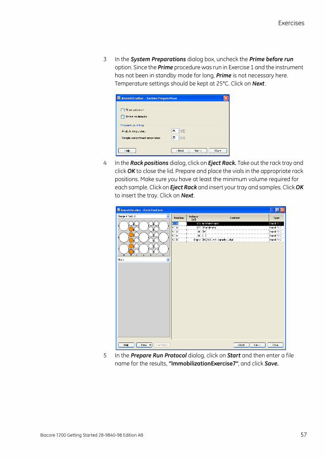
3 In the System Preparations dialog box, uncheck the Prime before run option. Since the Prime procedure was run in Exercise 1 and the instrument has not been in standby mode for long, Prime is not necessary here. Temperature settings should be kept at 25°C. Click on Next .
4 In the Rack positions dialog, click on Eject Rack. Take out the rack tray and click OK to close the lid. Prepare and place the vials in the appropriate rack positions. Make sure you have at least the minimum volume required for each sample. Click on Eject Rack and insert your tray and samples. Click OK to insert the tray. Click on Next .
5 In the Prepare Run Protocol dialog, click on Start and then enter a file name for the results, “ImmobilizationExercise7”, and click Save.
Biacore T200 Getting Started 28-9840-98 Edition AB 57
ExercisesExercise 6. Kinetic analysis
Kinetic assay set-upThe unmodified Flow cell 1 will be used as Reference surface (upstream of the active Flow cell 2).
Running buffer: HBS-EP+.
Regeneration solution: Glycine-HCl, pH 2.5
Preparations: Dilute the 2µ-globulin in running buffer to 32 nM (2,26 µl 2µ-globulin + 598 µl buffer). Prepare the concentration series from the 32 nM sample: mix 300 µl of the 32 nM solution with 300 µl running buffer to get the 16 nM concentration. Continue the dilution series to obtain the following: 32, 16, 8, 4 and 2 nM. 8 nM should be run in duplicate, and three zero samples should be included
6 In the Biacore T200 Control software, open the the Kinetics/Affinity wizard by choosing File: Open/New Wizard Template. Select Kinetics/Affinity and click New.
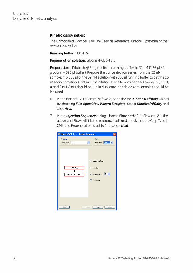
7 In the Injection Sequence dialog, choose Flow path: 2-1 (Flow cell 2 is the active and Flow cell 1 is the reference cell) and check that the Chip Type is CM5 and Regeneration is set to 1. Click on Next .
58 Biacore T200 Getting Started 28-9840-98 Edition AB
Exercises
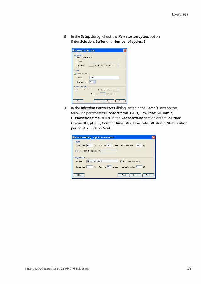
8 In the Setup dialog, check the Run startup cycles option. Enter Solution: Buffer and Number of cycles: 3.
9 In the Injection Parameters dialog, enter in the Sample section the following parameters: Contact time: 120 s, Flow rate: 30 µl/min, Dissociation time: 300 s. In the Regeneration section enter: Solution: Glycin-HCl, pH 2.5, Contact time: 30 s, Flow rate: 30 µl/min. Stabilization period: 0 s. Click on Next .
Biacore T200 Getting Started 28-9840-98 Edition AB 59
ExercisesExercise 6. Kinetic analysis
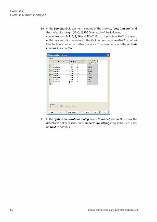
10 In the Samples dialog, enter the name of the analyte, “beta 2 micro”, and the molecular weight (MW), 11800 D for each of the following concentrations: 0, 2, 4, 8, 16 and 32 nM. Run a duplicate of 8 nM at the end of the concentration series and after that two zero samples (0 nM i.e buffer). Use the figure below for further guidance. The run order should be set to As entered. Click on Next .
11 In the System Preparations dialog, select Prime before run. Normalize the detector is not necessary and Temperature settings should be 25 °C. Click on Next to continue.
60 Biacore T200 Getting Started 28-9840-98 Edition AB
Exercises
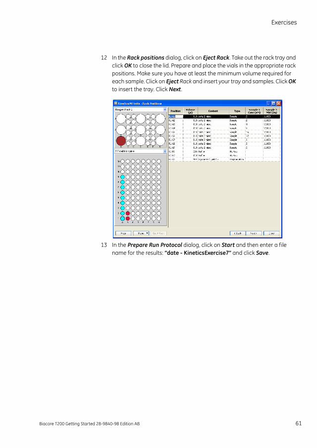
12 In the Rack positions dialog, click on Eject Rack. Take out the rack tray and click OK to close the lid. Prepare and place the vials in the appropriate rack positions. Make sure you have at least the minimum volume required for each sample. Click on Eject Rack and insert your tray and samples. Click OK to insert the tray. Click Next .
13 In the Prepare Run Protocol dialog, click on Start and then enter a file name for the results: “date - KineticsExercise7” and click Save.
Biacore T200 Getting Started 28-9840-98 Edition AB 61
ExercisesExercise 6. Kinetic analysis
Evaluation of the results14 Start Biacore T200 Evaluation software: click on the Start menu and select
Biacore T200 Evaluation from the Biacore menu.
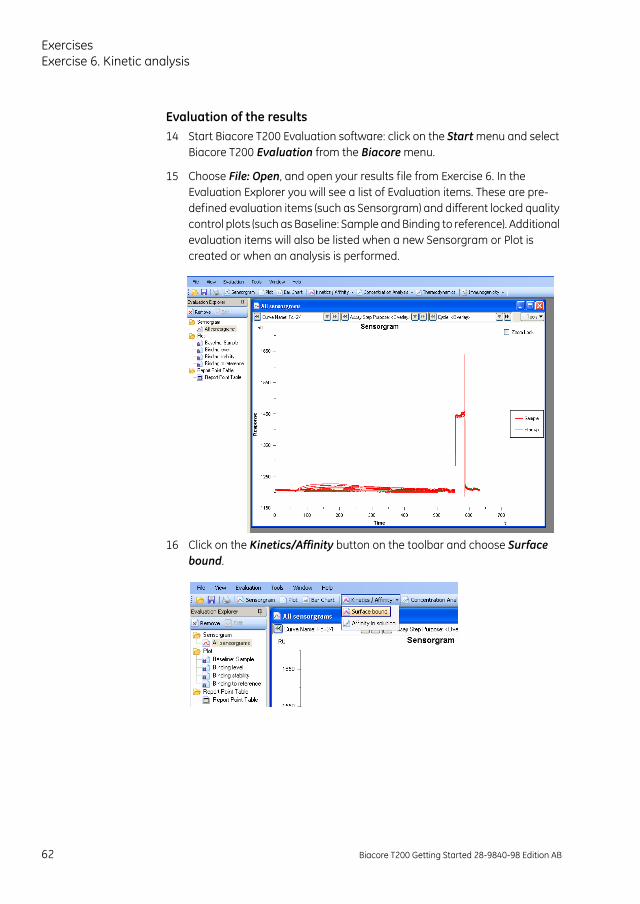
15 Choose File: Open, and open your results file from Exercise 6. In the Evaluation Explorer you will see a list of Evaluation items. These are pre-defined evaluation items (such as Sensorgram) and different locked quality control plots (such as Baseline: Sample and Binding to reference). Additional evaluation items will also be listed when a new Sensorgram or Plot is created or when an analysis is performed.
16 Click on the Kinetics/Affinity button on the toolbar and choose Surface bound.
62 Biacore T200 Getting Started 28-9840-98 Edition AB
Exercises
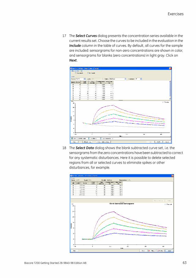
17 The Select Curves dialog presents the concentration series available in the current results set. Choose the curves to be included in the evaluation in the Include column in the table of curves. By default, all curves for the sample are included: sensorgrams for non-zero concentrations are shown in color, and sensorgrams for blanks (zero concentrations) in light gray. Click on Next .
18 The Select Data dialog shows the blank subtracted curve set, i.e. the sensorgrams from the zero concentrations have been subtracted to correct for any systematic disturbances. Here it is possible to delete selected regions from all or selected curves to eliminate spikes or other disturbances, for example.
Biacore T200 Getting Started 28-9840-98 Edition AB 63
ExercisesExercise 6. Kinetic analysis
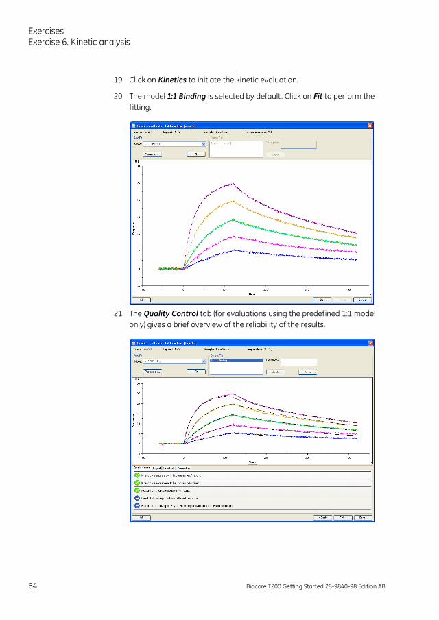
19 Click on Kinetics to initiate the kinetic evaluation.
20 The model 1:1 Binding is selected by default. Click on Fit to perform the fitting.
21 The Quality Control tab (for evaluations using the predefined 1:1 model only) gives a brief overview of the reliability of the results.
64 Biacore T200 Getting Started 28-9840-98 Edition AB
Exercises
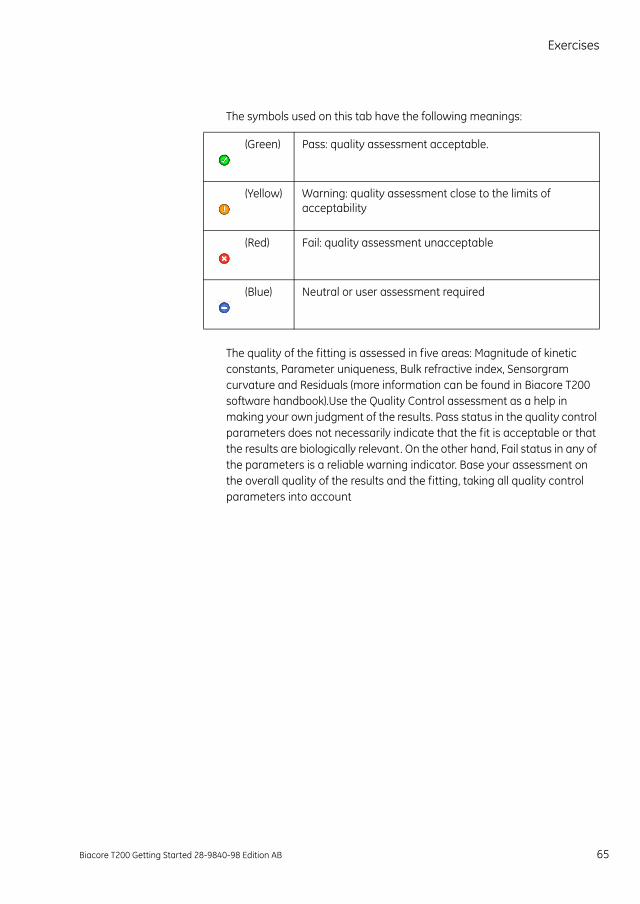
The symbols used on this tab have the following meanings:
The quality of the fitting is assessed in five areas: Magnitude of kinetic constants, Parameter uniqueness, Bulk refractive index, Sensorgram curvature and Residuals (more information can be found in Biacore T200 software handbook).Use the Quality Control assessment as a help in making your own judgment of the results. Pass status in the quality control parameters does not necessarily indicate that the fit is acceptable or that the results are biologically relevant. On the other hand, Fail status in any of the parameters is a reliable warning indicator. Base your assessment on the overall quality of the results and the fitting, taking all quality control parameters into account
(Green) Pass: quality assessment acceptable.
(Yellow) Warning: quality assessment close to the limits of acceptability
(Red) Fail: quality assessment unacceptable
(Blue) Neutral or user assessment required
Biacore T200 Getting Started 28-9840-98 Edition AB 65
ExercisesExercise 6. Kinetic analysis
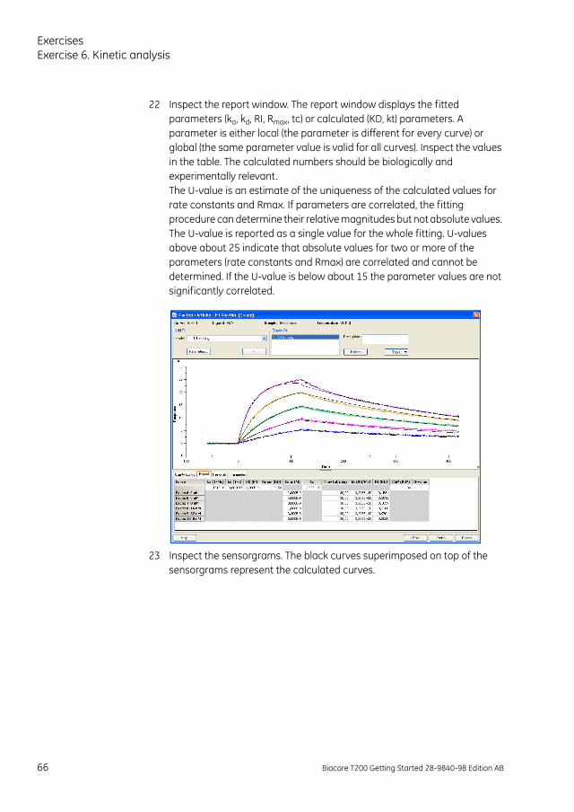
22 Inspect the report window. The report window displays the fitted parameters (ka, kd, RI, Rmax, tc) or calculated (KD, kt) parameters. A parameter is either local (the parameter is different for every curve) or global (the same parameter value is valid for all curves). Inspect the values in the table. The calculated numbers should be biologically and experimentally relevant. The U-value is an estimate of the uniqueness of the calculated values for rate constants and Rmax. If parameters are correlated, the fitting procedure can determine their relative magnitudes but not absolute values. The U-value is reported as a single value for the whole fitting. U-values above about 25 indicate that absolute values for two or more of the parameters (rate constants and Rmax) are correlated and cannot be determined. If the U-value is below about 15 the parameter values are not significantly correlated.
23 Inspect the sensorgrams. The black curves superimposed on top of the sensorgrams represent the calculated curves.
66 Biacore T200 Getting Started 28-9840-98 Edition AB
Exercises
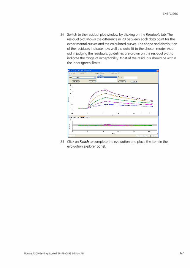
24 Switch to the residual plot window by clicking on the Residuals tab. The residual plot shows the difference in RU between each data point for the experimental curves and the calculated curves. The shape and distribution of the residuals indicate how well the data fit to the chosen model. As an aid in judging the residuals, guidelines are drawn on the residual plot to indicate the range of acceptability. Most of the residuals should be within the inner (green) limits
25 Click on Finish to complete the evaluation and place the item in the evaluation explorer panel.
Biacore T200 Getting Started 28-9840-98 Edition AB 67

ExercisesExercise 6. Kinetic analysis
68 Biacore T200 Getting Started 28-9840-98 Edition AB
Biacore T200 routine maintenance
Biacore T200 routine maintenance
Regular maintenance of Biacore T200 is of the utmost importance for reliable results. It is important to avoid contamination, such as microbial growth and adsorbed proteins in the liquid handling system.
In Biacore T200 Control Software, maintenance procedures can be found under Tools: More Tools. In the BIAmaintenance Kit Type 2 (BR-1006-51) you will find the solutions required to run the different procedures. Use the Maintenance Chip when running methods Desorb, Desorb and Sanitize and Wash Buffer Tubing. Inspect both sides of the chip before use. If necessary, clean the surface with water and wipe it dry.
The local field service representative provides preventive maintenance service every 6 or 12 months. Our personnel will be happy to discuss the service frequency most suitable to your situation.
Daily maintenance• Prepare fresh buffers.
• Change to fresh water and check that the waste bottle is not full.
• Flush the system by choosing Tools: Prime.
• Between experiments, maintain a continuous buffer flow by selecting Tools: Standby.
• If you intend to leave the instrument for more than four days, shut down the instrument by choosing Tools: Shutdown.
Weekly maintenance• Run Desorb from the menu Tools: More Tools to clean the liquid system
• Inspect tube fittings and pumps to check for leaks and salt deposits. If you find leaks at tube fittings, clean with water and tighten the connections. If you find leaks in either of the syringe pumps, call your service representative.
Biacore T200 Getting Started 28-9840-98 Edition AB 69
Biacore T200 routine maintenance
Monthly maintenance• Run Desorb and Sanitize from the menu Tools: More Tools to remove any
adsorbed material in the liquid system and disinfect the system.
• Run System Check from the menu Tools: More Tools, according to the instructions in the wizard.
• Clean the instrument cover.
• Inspect the sample compartment and remove spillage with water or ethanol if required.
When necessary• Run Wash Buffer Tubing to clean buffer tubing and remove adsorbed
material (e.g. detergent).
• Run Empty Buffer Tubing (by selecting Tools: More Tools) to clean and empty all buffer tubing after using several buffers, and when buffer tubing will not be used.
70 Biacore T200 Getting Started 28-9840-98 Edition AB


28-9840-98 AB 10/2013
For contact information for your local office,please visitwww.biacore.com
GE Healthcare Bio-Sciences ABBjörkgatan 30751 84 UppsalaSweden
www.biacore.com
GE and GE monogram are trademarks of General Electric Company.
Biacore is a trademark of GE Healthcare companies.
All third party trademarks are the property of their respective owners.
© 2005-2013 General Electric Company—All rights reserved.First published Jun. 2010
All goods and services are sold subject to the terms and conditions of sale of the company within GE Healthcare which supplies them. A copy of these terms and conditions is available on request. Contact your local GE Healthcare representative for the most current information.
GE Healthcare UK LtdAmersham Place, Little Chalfont, Buckinghamshire, HP7 9NA, UK
GE Healthcare Bio-Sciences Corp800 Centennial Avenue, P.O. Box 1327, Piscataway, NJ 08855-1327, USA
GE Healthcare Europe GmbHMunzinger Strasse 5, D-79111 Freiburg, Germany
GE Healthcare Bio-Sciences KKSanken Bldg. 3-25-1, Hyakunincho, Shinjuku-ku, Tokyo 169-0073, Japan