berechnung der horizontalbelastung von schubwanden … · berechnung der horizontalbelastung von...
TRANSCRIPT
Berechnung der Horizontalbelastung von Schubwanden aus Ziegeln, die I· rt -
durch Deckenplatten verbunden sind B. P. Sinha, A.W. Hendry, Departcmcnt of Civil Enginccring and Building Scicnce, Univeis)t y of Edinbnrgh, Schonland
Kurzfassung
Flir die Bcreclmung VOll ll1chrgeschossigcn Maucrwcrkskonstruktionen ist es iiblich, entweder die Qucrwandc idealisicrt aIs cinen Rah mcn mie brcircn SticIen bzw. aIs cinzelnc Kragtdiger, wobei dic Dcckcn ais starrc, gelenkig verbundene Aussteifungen wirken, zu bchandeln odee die Dccken durch ein Kontimllllll (Sch li bverbind ungsverfahren) zu ersctzen. Versl1che an Modellen lInd Prüfkürpern in natürlicher GróBe zcigten jcdoch, daJ3 das Verhaltcn VOIl
Querwandcn aus Ziegclnlaucrwerk bei horizontalcm Lastangriff nicht dCJ11 mit solchen Mechoden vorhcrbcsti 111ll1tcn Vcrhaltcll entspricllt. Der Ullterschicd zwischen den expcri nft:nteHcn und thcoretischcn Ergcbnissen ist vermU[lich auE dic Tatsaehc zurlickzuführen, dal3 für das Zusammcnwirkcll von verschicdenen Elemclltcn Annahmcn angesetzt wcrdcn, die nieht für aHc in der Praxis vcrwendetcn Ausführungsmethoden ulld Fugcllmatcrialien zutrcHen . In dicsclll Bcitrag wcrdcn kurz einige Ursachen dieser fchlenden Ubcreinstimmung zwischcll dcn theoretischcn lInd den cxperi Illcntcllen Ergebnissen bcsprochcn und cine Bcmessungsmethode solcher Bauwcrke hei Windbe!astung angcdeutet. Ferner wird auch auE die Notwcndigkeit cincr gcnallen F.rmittlllng der Stcifigkeit der Verbindllngsclemente cingegangen . Diese ist cine der Verandcrlichen, wckhc das Verhalten von Mallcrwcrkskollstruktionen mit Qucrwandcll weitgchend bccinflussen.
The Lateral Load Analysis of Brick Multi-Storey shear-wall structures
In structuraI design brick l11ulti-storey, shear-wall structures are commonly idealised and replaccd by a widecolumn Erame or the slabs are replaced by a cominUU111 (shear cOIUlection method) or the wllls are treared as individual cantilevers (the slabs merely acting as rigid pin-connected struts). The behaviour of actual brick shear \VaU structurcs undcr lateral loading difEcrs Erom that predicted by t!l ese methods, as obscrvcd both in case of modcl and full-scaJc experi mcnts. The difference between the experimemal and theoretical results ma)' be due to the assumptions regarding the interaction of thc clemcl1ts, which in a practical structure may nor be valid due to the method of constructioll and jointing materiaIs. The paper looks briefly into thc cause of observed differences bctween theorctical and experimenta l results and suggests a possiblc method for thc dcsign of brick structures sub;ccrcd to wind loading. The paper also discl1sses the i mportance of assessing correetly the stiffncss of the intercOlUlccting mediul11, one oE the variables which affects the bchaviour of brick shcar wall structures to a grClt extem.
Analyse des effets dus aux charges latérales dans les immeubles-tour
Pour les calculs des immcubles-tour, ct notamment pour l'étudc des effets dus aux charges latérales, on part en général d'une structure idéalisée. On remplace la bâriment soit par une ossature à cololUles rigidcs, soir par une ossature à poutrcs rigides (calcul dcs cisaillements dans Ics mucs). Une autre méthode consiste à considérer les Illurs commc étant dcs poutres individuelles, encastrées dans Ics fondements (Ies planchcrs étant dans cc cas des pOlltres horizontales articulécs). Le comportement réel des bâtimcnts ne répond à aucune de ces hypotheses, commc le démontre tanr l' cssai sur maqucttc que celui sur bâtiment de grandclIr nature. On pourrait attribllcr la différence entre Ics résultats d'essais et les calcules théoriqlles allx hypothcscs concernant I'interaction des élémcnrs qui, dans une structure réelle, pcut trcs bicn llC pas être valable, compte tcnu de la méthode de construction et dcs matériaux de liaison. L' articlc expose trcs bricvemenr b ClUSC dcs divcrgcnces constatées entre Ics résultacs expérimenraux er propose unc méthodc pratique pour le calc111 des eHets dus au vento Lcs alltcurs soulignent l'importance d'une évall1ation précisc de la rigidité dcs no.'uds, qui constitue 1\1I1e des variablcs ayant une grande inflllenec sur Ie co mportcment dcs structures.
Schubwande sind cin wirksamcs Mittel zur Erzielung von Steifigkeit in Illodcrnen, vielgeschossigen Tragkonstruktionen. D erartige Wandc bilden im Zusammcnwirken mit den GcschoBdeckcl1 ein hochgradig llnbestimmtcs System. Eine genaue rcclmerische Umcrsuchllng ist schwierig, so daB fiir die Bcrcchnung d~s Dallwerk mcistens idcalisicrt lllld dureh einen brcitstieligcn Rahmcn [51 ersetzt wird; man ersctzt auch die Oecken durch ein Kominuum (3) (Schllbverbllnd-Verbhren) oder dic Wande werdcn wie cinzelne Kragarme behandclt (wobei die Oecken lediglich wic steife, Pllnktvcrforlllullg verbundenc AlIssteifllBgen wirkcn). Wahrend in der Praxis di esc Vcrfahrcn Hir die rechnerische Umcrsuchung llnd dcn Enrwurf von Reihen ebeBer Wande angcwandt werden, die dllrch D cckcn oder Balkcn verbllnden sind, stellt die rechllcrischc Unterstlchung eines zusammengcsctztcn, drcidimcnsionalen, viclgcschossigcll Bamvcrks cin lloch schwierigeres
Problem dar. A ul3erdclll wurdc beobachtet, daB dic Ergcbnisse dieser Berechnungsverfahren sogar fiir den einfachen zweidimensionalen Fali nicht mit dem Verhalten wirklicher Schubwandkonstruktionen von Zicgcln übercinsti I1lmten [1 J. Sie konnen daher nicht allgcmein ais ein Normberechnllngsverfahren angewandt werden. Der groBc Unterschied zwischen den expcrimentellen llnd theoretischen Ergcbnisscn kalUl auf die Annahmen hinsichdich der Wechsehvirkllng zwischcn den einzelnen Balltcilen zuriickgcführt wcrden, die in einem wirklichen Bauwerk wegell der verwendeten Konstruktionsverfahrcn und Verbindungsmittel nicht illll11cr gi.iltig sind. Diescr Aufsatz soU kurz dic Ursache dcs Widerspruehs zwisehcn den rheoretischen und expcrimentc1len Ergebnissen bclellchten. Unter Heranzichllng expcrimenrcllcr Ergcbnisse werdcll llloglichc verfahren fi.ir dic BereclUlung von Zicgclballten lInter Windlast vorgeschlagen [1 , 2, 4J.
354
Berechnung des Bauwerks
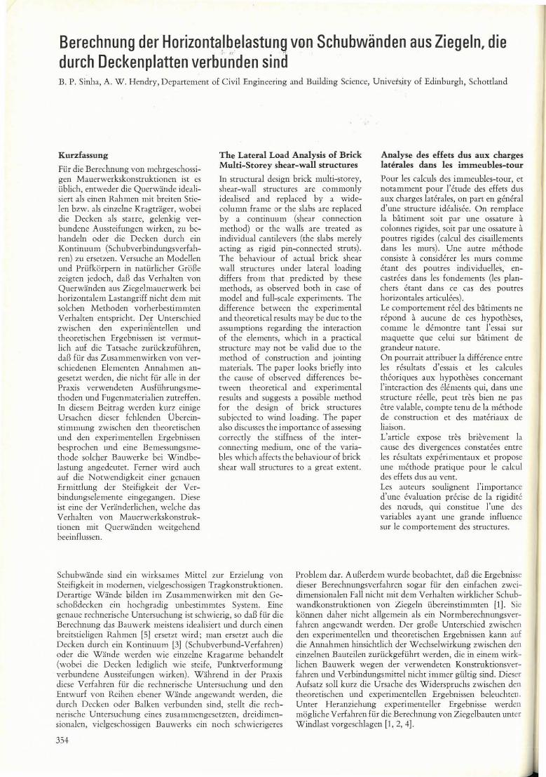
Das in dcn Abb. 1 und 2 gezeigte Bauwerk wird durch gcdachte Wandc llnd Balken crsetzr, wclche die gleichcn Flachcn und Tragheitsmomemc wic das Bauwerk allfweisen. Die Decken sind dllrch Balkcn crsetzt, dercn wirksamc Brei te gleich der vollen Dcckenbrcitc angenOIl1J1lcn w ird. Dic Vcrformllngcn infolgc Axiallast in dcn Balken sowie die Axial- und Schubverformllngcn der Stiitzcn wcrden vernachHissigt. Ourch diesc N a:hc rungcn künnen dic Ersatzsystcme lcicht berechnct werdcn, vorallSgcsetzt , daR die Wertc der elastischen Kennwcne bckannt sind. Der Einfachheit halber wurde für die nachsrchend aufgcfiihn e Bereclmllng das KrafrgroBcnverfahren 3ngcwandc. Man beachtc dic Drehllng 0 1 der Wandc am Oeckenan,chl llG (Abb. 3).
M 0, = of' -E r dx - [R, + R, + R, ... + Rnl· l · h (s. Abb.l)( I)
li,' W
Hierbci ist Ew gleich de 111 Elastiziúeslllodul der Wand ; Iw Tragheicsmomem und Mdx gleich der Flache uncer der Bicgemomcmenl inie infolgc der aufgcbrach ren Last.
(2)
Nach Abb. 3 kanll dic Oeckc \Vic zwci an jcdclll Endc mie de r unbckanntcn Kraft RI bclastcte Kragarmc bchandel t wcrdcn.
Daher
11 =
dic wirksamc Langc dcs Balkcns wird inncrhalb der \Verte 11 und 12 angcnoml11cn.
Grcnz-(3)
Eb, Ib sind Elastizitatsl1lodul bcziclH1Ilgswcisc Traghcitsl1loll1cnr der Dcckc
ALI, (1), (2) lIl1d (3) ergibt , ich
R, (_1_' _ + ~) + (R, + R, ... + Rn) I' h 3 Eb 11) Ew lw Ew Iw
[Mdx]h. 1 (4) Ew I..... o
In der gleichen Art crhãl t man n Gleichungen flir n Unbekannte. Welill man almi l11l11t, daB h = 1 ist, was der Rahmcnberechnung cncspricht und die Glcichung in Matrixform aufstell t, erhalt man:
R, E ..... -Iw I'· h
E ..... Iw
J3 111' h
U,
U,
- +-- U n 3Eb1b E .. Iw
Symmctrisch
( I' 312h )
3Eb1b + E ..... I ..... 312h Ew Iv.:
JhM J'h M dx Hierbei ist U, ~ I. -E- r - dx, U, = 1 . EI "'w. (5)
o ww o ww
Abb. 1 : Grund- und Aufrjf, \lon Modell 1 Fig. 1: Showing lhe plan and eleval ion 01 Model 1
n T
Il
r~ii j~~- - ~ ~--~ - ' ~ ~
,,·,~r: " , J
-, , • _ o , , n, _L'" ,
.ti. f .., c::==::=:l c::==::::::J , i DI t
1"tJ .. ~Lj __ 0 -+-",- "'--'l'S~ ___ '1· _ _ _ ~
h~ndrlu/Plan
Abb. 2: Gru nd- und Aufri& von Modell 2 Fig. 2 : Showing lhe plan and elevation of Model 2
Abb.3: Linke Hãllte der KonSlrukl ion Fig. 3 : Left hall 01 lhe structure
SCh~ r llchse /Ce n t r o ld
Ptlinl of
ConlrQf'.lI~r.
355
Wenn man davon ausgeht, daB der Balken zwisehen der geometrisehen Mittellinie und der AuBenseite der Sehubwand unendlich steif ist, d. h. cinem breitsticligen Rahrnen emsprieht, crgibt sich !olgende Gleichung:
R,
R,
E",,' I ..... 2 J2 . h
Ew I""
U,
U,
U,
U n (6)
W cnn die Unbckannren einrnal gcfllnden wurden, cl1twcder dureh Losung des Glciehungssystems oder dureh Matrixinversion, so kann man die sieh ergebende Biegemomentenlinie dureh Oberlagcrung erhalten. In der gleiehen Art kann man die Durchbiegung der KOllStruktion nach dcm KraftgroBcnverfahrcn erhalten. Die SpalU1Ungen in' den rcchten und linken Wanden in irgendeinem Querschnitt ~rgeben sich aus
ist
R MY W b . I . R MY W A + 1;"-1\ eZle nmgswelse T -iw-T'
R ~ Axialkra!t M = sich ergebcndcs Momem in der Wand A ~ Wandflache I w = Traghcitsmomcnt der Wand
Hierbei
Y = Abstand der Randfaser von der Schwerachse der Wand W = Eigengewicht des Bauwerks oberhalb des bctrachtetcn Schnittcs
Die GroBtspannungen sollten dic nach den Ballbestil11l1l11ngen zuHissige Sparunmg nicht überschreiten. AllBerdem sind keinc ZllgspaIUwngcn in irgcndcinem Wandql1crschnitt erlaubt.
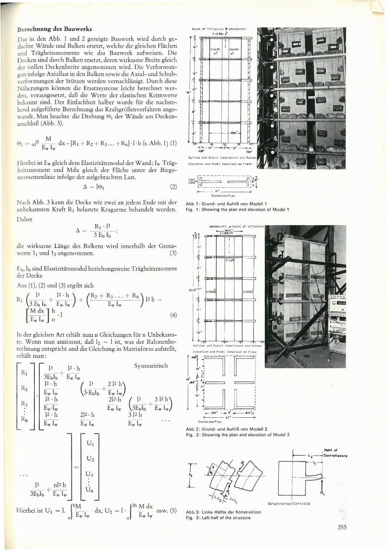
Vergleich mitden Versuchsergebnissen : Die allS der obigen Bereclmung nach Gleichllng 5 erhalrenen DlIrchbiegllngen für die in den Abb. 1 und 2 gezeigtcn Modelle werdcn in dCIl Abb. 4 und 5 mit den Versllchsergebnissen verglichcIl. Dic Werte für die Elastizitarsllloduln dcsZicgelmauerwerksunddes Betons im Modell wurdcn durch Bicgeversllche an einfachen Balkcn beziehungsweise Druckversllche an Zylindern ermittelt. für Ziegclmauerwcrk im narürlichen MaBstab \Vllrde der Elastizitatsmodul in einem Druckversuch crmittelt. Es besrcht eine gure Übcreinstiml11l1ng zwischen den experimcntellen llnd den rechnerischen Ergebnissen. In dcn A bb. 4 lInd 5 \Verden auch die Ergebnisse der rechnerischen Untersllchung am brcitstieligen Rahmen (G leichl1ng 6), nach dem Schubverbllnd tllld dem Kragannverfahrell gezeigt. Die erstCIl beiden dieser Verfahren schiüzCll die Durchbiegung des Bauwerks zu niedrig, das Kragarmverfahren schatzt sic zu hoch ab (Abb. 4 l1nd 5). Die Widerspriiche sind hauptsachlich auE das Al1ftrctcn unterschiedlichcr ScheibenkrãEte in den gleichwcrtigcn Gcbãudcn zuriickzufiihren (Abb. 6 und 8), die sich aus den llnterschicdlichen Annahmen crgeben, die den verschiedenen Verfahren zugrunde liegen. Der einzigc Unterschied zwischen den
356
s-
.1 s ,. " ~
'" ~ · · •
"
~
"
"
~ , g u
VOfQ,,!chlIlQen .. Methode f!.sIJ:gud m!lhgs! o
!!'!:.!.!.
., 150X 10 in.
Abb.4: e.perimentelle und rechnerische Durchbiegung des Modells 1 (Abb. 1) Fig. 4: e.perimental and analytical dellection of Model 1 (Fig. 1)
'"
"
"'''p!!;""nlol _ ...
~ ""lhod _ ..
Ourcllb le;ung/Oet lect ion
Abb. 5 : Durchbiegung des Modells 2 (Abb. 2) nach verschiedenen Berechnungs· verlahren und den Versuchsergebnissen Fig. 5. Deflection 01 Model2 (Fig.2) by different analytical methods and the test results
Matrizcn 5 und 6 liegt in der Hauptdiagonalen, und da die Glieder i 111 zweiren Falle cntsprechcnd dem breitstieligcn Rahmen kleiner sind, wi rd der Scheibcnschub vielfach heher abgeschãtzt aIs vergleichsweise im erstcren Fali (FalI 5), der ciner Rahmenbercchl1l1l1g entspricht. Dics führt zu ciner zu niedrigen Abschatzung des Bicgemomelltes ulld der Durchbiegung beim Breitstiel-Vcrfahren. Dies trifft gleichfaUs beim Schubvcrbund-vcrfahren zu, bei dem ein Kominuull1 zwischcn den Wandcn angcnOllll11en wird.
o - --
" Scholl/Shur
Gr undllod..I l 1 (AbO . 1)
K!)'_loIod.L·l\f'l . 1 J
,I
" 9 0 lbl' .
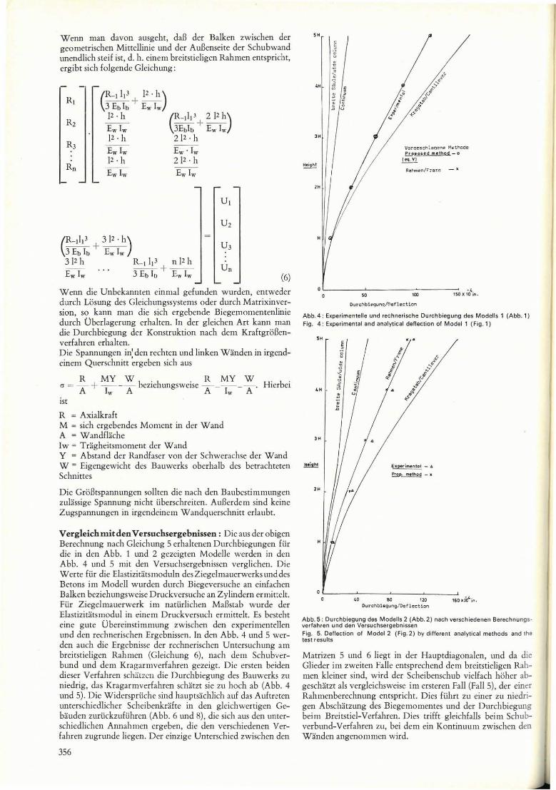
Abb. 6: Schubverteilung irn Verbundbaukõr pe. Fig. 6: Shear diSlribution in connecting medium
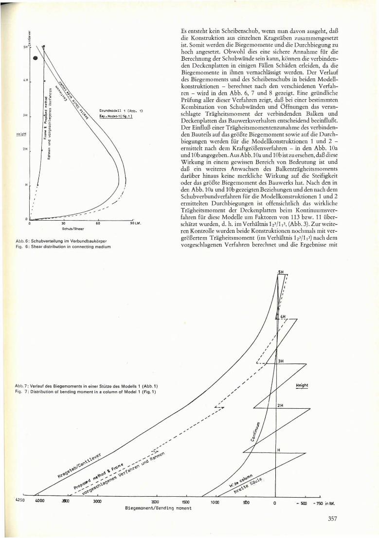
Abb. 7: Verlauf des Biegernoments in einer Stütze des ModeUs 1 (Abb. l) Fig. 7: Oislribution of bending mornen! in a colurnn of Model 1 (Fig. 1)
Es cntsteht kein Schcibenschub, wcnn man davan ausgeht. daB die Konstruktion aus einzelnen Kragstãben ZUSJ l11l11cngesetzt
isc. Somir \Verden d ie Biegcmo mente und dic Ourchbiegung l U
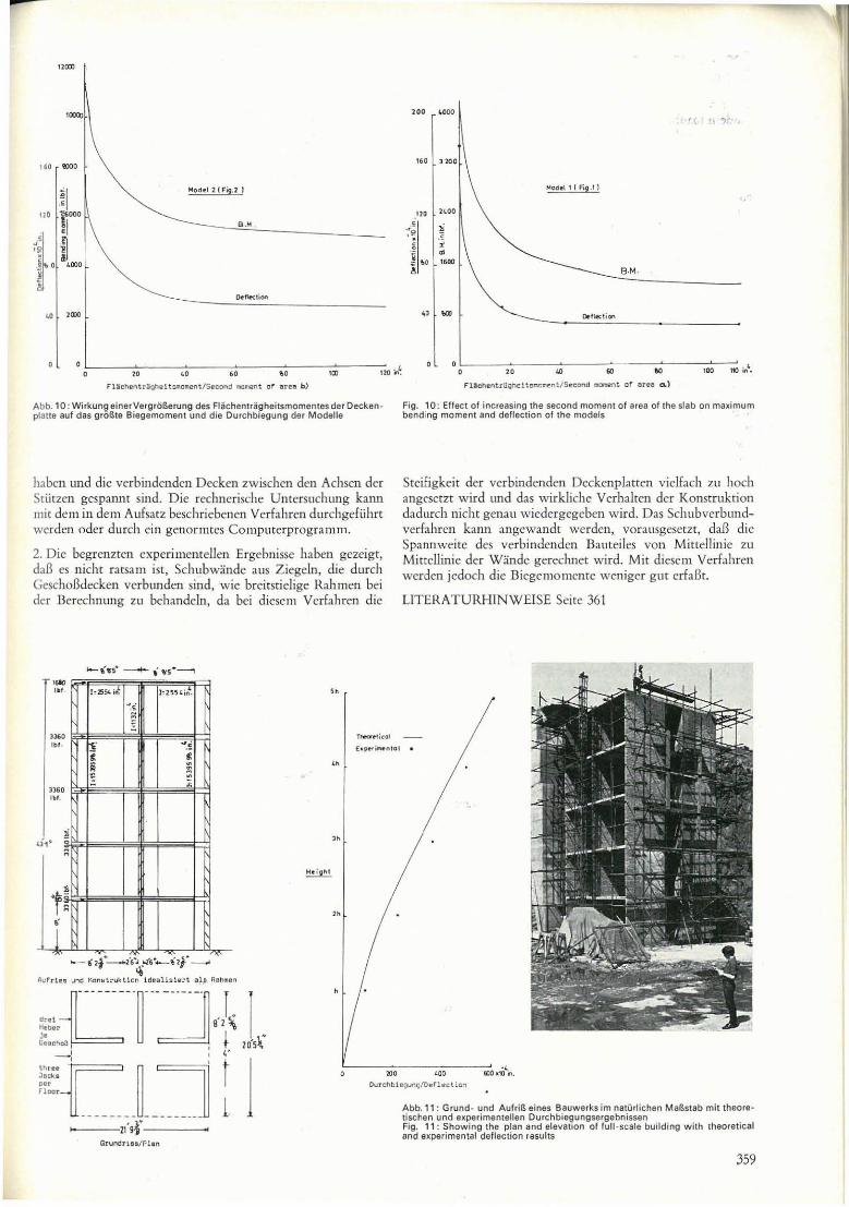
hoch angesetzt. O bwohl dies cine sichcre Annah mc fi.ir die Bercchnung der Schubwandc sein kann, kOlmen dic vcrbindenden Deckenpl:mcn in emigcn Fa:llen Schãdcn erleiden, da die Biegcmomente in ihncn vem achlassigt werden. Ocr Verlauf des Biegemo ments und des Scheibenschubs in beiden Modcllkonstruktioncn - berechncr nach den vcrschiedenen Verfahren - wird in den Abb. 6, 7 und 8 gezcigt. Einc grlindlichc Prüfung aUcr dicser verfahren zeigt, daB bei einer bcstimmtcn Kombination von Schubwãnden und Ü ffnungen das veranschlagte Traghcitsmomem der verbilldenden Balken und Deckenplatten das Bauwcrksverhalten em scheidend bccinfluBt. Der EinfluB einer Tragheitsmomentenzunahmc des verbindenden Bameils auf das groBtc Biegemomcnt sowie auE die Durchbiegungen wcrdcn für dic Modellkonstruktionen 1 und 2 -ermittclt nach dcm Kraftg roBcnvcrfahrcn - in dcn Abb. 10a und 1 Ob angegeben. Aus Abb. lOa und IOb ist zu ersehen, daB diese Wirkung in cincm gewissen Bereich von Bedclltung ist und daB eiu weiteres Anwachscn des Balkemragheitsmo mem s darliber hinaus keine merkliche Wirkung allf dic Stcifigkeit oder das groBtc Biegemomem des Bauwerks hat. N ach deu in den Abb. lOa und lOb gezcigtenBezichungen und dcn nach dem Schubvcrbundvcd ahrcn Hir die Modellkonstruktioncn 1 und 2 ermitteltcn Durchbiegungcn ist oHensichtlich das wirkliche Tragheitsmo ment der Dcckcnplatten bcim Kontinuumsvcrfahrcn Hir diesc Modclle um Faktorcn von 113 bzw. 11 übcrschatzt w urden, d. h. im Vcrhaltnis h 3/ 1 13, (Abb. 3). Z ur weiteren Kontrolle w urdcn beidc Konstruktioncn nochmals mit vcrgroBcrtem TragheitsmomcItt (im Vcrhaltnis 123/11 3) nach dem vorgcschlagcncn Verfahrcn hcrechnet und dic Ergehnisse mie
/
, -'
Blegemoment/ Bending moment
357
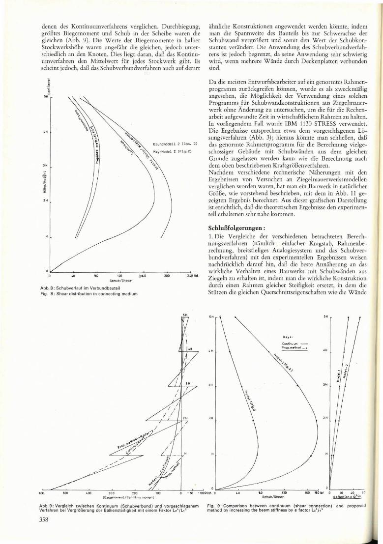
denen dcs Konrinllllmverfahrens verglichen. Durchbiegllng, groBres Biegemoment und Schub in der Scheibe waren die gleichen (Abb. 9). Die Werte der Biegemomente in halber Stockwerkshohe waren lIngefahr die gleichen, jedoch untcrschiedlich an den Knoten. Dies liegt daran, daB das Kontinllul11verfahren deo Mittclwert fUr jedeS" Stockwerk gibt. Es scheint jedoch, daB das Schubverbundverfahren auch auf dcrart
, .~ 8
"
Grundmod!!ll 2 (Abb . ~)
O ~----~'OC-----~'~O------~'~~----~I='O:-----~'=OOC-----,~W" ~ Schub/Shur
Abb. 8: Schubverlauf im Verbundbauteil Fig. 8: Shear distribution in connecl ing medium
; ;
i / ,
/ i «---+--"---f,t!;
Blegern"", .. nt /aenr1 lng _ent
almlichc Konstruktioncn angcwendet werden konme, indem man dic Spannweite des Bautcils bis zur Schwerachse der Schubwand vergroBert und so mit den Wert der Schllbkonstantcn verandcrt. Die Anwendung dcs Schubverbundverfahrens ist jedoch begrcnzt, da scine Anwcndung sehr schwierig wird, wcnn tllchrere Wande durch Dcckenplatten vcrbunden sind.
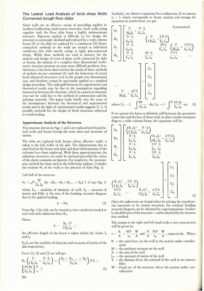
Da die meisten Emwurfsbearbciter auE cin genormtes Rahmenprogramm zurückgreifen konnen, wurde es aIs zwcckmaBig angesehcn, dic Moglichkeit der Verwendung cines solchen Programms für Schubwandkonstruktionen aus Ziegc1mauerwerk ohne Anderung Z l1 tmtersuchen, um die für die Rcchcnarbeit aufgcwandte Zeit in winschaftlichem Rahmen zu halten. In vorliegendem Fali wurde IBM 1130 STRESS verwender. Die Ergebnissc emsprcchen etwa dem vorgeschlagenen LOsllngsverfahren (Abb. 3); hieraus konnte man schlieBen, daB das genormte Rahmcnprogramm flir die Berechnuug vielgeschossiger Gebaude mi t Schllbwandcn aus dem gleichcn Grundc zugelassen werden kann wie dic Berechnung nach dem oben bcschriebencn KraftgroBenvcrfahrcn. Nachdem verschiedene rechnerische Nahcrungen mit dcn Ergebnissen von Vcrsllchcn an Ziegelmauerwerksmodellen verglichen wordcn warcn, hat man cin Bauwerk in nati.irlicher GrõBe, wie vorstehend beschrieben, mit dem in Abb. 11 gezeigten Ergebnis bcrcchnet. AlIs dicscr grafischcn Darstcllung ist ersichdich, daS die rheoretischen Ergebnisse den cxpcri mentell erhaltencn schr nahe ko mmcn.
Schlullfolgerungen : 1. Die Vergleichc der verschiedencn betrachreten Berechnungsverfahrcn (namlich; einfacher Kragstab, Rah mcnberechnung, breitstieliges Analogiesystclll und das Schubverbundverfahren) mit deu expertl11cntellen Ergebnisscn weisen nachdrücklich darauf hin, daB die beste AIUlaherung al1 das wirkJiche Verhaltcn eincs Bauwerks mit Schubwanden JUS
Ziegeln zu erhaltcn ist, indem man die wirkliche Konstruktion durch cinen Rah men gleichcr Steifigkcit ersetzt, in dCI11 dic Stiitzcn die gleichen Qucrschnittseigenschaftcn wie die Wandc
P'op .... 'lhod _ o
,
Abb. 9 : Vergleich zwischen Kontinuum (Schubverbund) und vorgeschlagenem Fig. 9: Comparison between continuum (shea r con nection) and proposed Verfahren bei VergrõBerung der BaJkensteifigkeit mit einem Faktor L2~/ L,~ method bV increasing the beam sti ffness bv a tactor LI',,~
358
"""
"""
Modfl 2!F;,,p )
9.104.
OetlKl;on
" ,""
~----~,~,------~,,~----~,,~----~.,~----~,oo~----~n,o~ fUlchentrlahe lt""," .. ent/Second lIIIIIIIent ar ena b)
Abb. 10 : Wirkung einerVergtõ~erung des Flãchenlragheitsmomenlesder Oecken platte auf das grõl!te Biegemoment und die Durchbiegung der Modelle
habcn und dic verbindcndell Decken zwischen den Achsen der Stii tzen gcspannt sind. Die rechncrische UntcrslIchung kann mit dCI11 in dem Aufsatz beschricbcllcn Verfahrcn durchgefiihrt wcrdcn odee durch cin genormtcs Computerprograllll11.
2. Die begrenzrcn experimentellcll Ergebnisse haben gezeigt, daB cs nicht ratsa m isto Sclmbwande aus Ziegcln, die durch GcschoBdecken vcrbundcn sind, \Vie breitstieligc Rahmen hei der llerechnung zu behandeln, da bei diesclll V crfahren dic
'" ""
'" "" r.llXltt , ( FiR ol)
'" 2~OO .. ,
~I! ., , , ~t.O • "., • B·M.
" w OtflKli(ln
'~, ------~,~,------~,,;--------;.,;------;,,;:-------;;'.,;;-----;;HO it.'.
Fig. 10 : Effecl of increasing lhe second momenl 01 afea of lhe slab on maMimum bending moment and delleclion of lhe models
Steifigkeit der verbindcnden Deckcnplatrcn viclfach zu hoch angcsetzt wird und das wirkliche Verhalten der Konstruktion dadurch nicht genau wicdergcgcben wird. Das Schllbverbllndverfahren kann angewandt wcrden, vorausgesctzt, da.B dic Spannwcitc dcs verbindcnden Bauteiles von Mittcllinic zu Mittellinic der Wande gerechnct wird. Mit dicscm Verfahrcll werdcn jedoch dic Biegemolllcntc weniger gur erfaRt.
LITERATURHINWEISE Seire 361
Ttwa-r! iCOI
E.pf'fÕlllentat • • 33&0 I$o$''===$==lll=i~==~"~'::::;:! I~I.
'-- úf_Ú'~"'6·-·i1r---.. Aufrl n und l\on~tru~t1on ld"Blls1ert al, R~""'an
Grundrlu/Plan
"
DurChb I couna/Oef lect i O"
Abb. 11: Grund- und AufriB eines Bauwerks im naturlichen MaBstab mit theore tischen und eMperimentellen Ourchbiegungsergebnissen Fig. 11: Showing the plan and elevation of full-scale building wilh theoretical and eMperimenlal dellection results
359
The Lateral Load Analysis af brick shear Walls Cannected traugh floar slabs
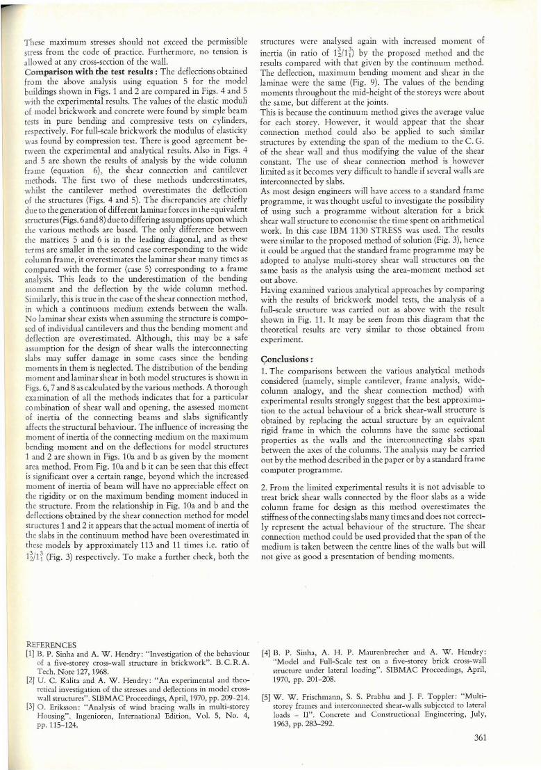
Shear walls are an cffcctive means Df providing rigidicy in modem loadbearing mulrj-storey structures. Such walls acting togcthcr with che {loor slabs focm a highly indetcrminate structure. Rigorous analysis is difficult, 50 for design the srructure is commonly idealised and repbced by a wide colul1m frame [51 cc the slahs are replaccd by a cominuull1 [3J (shearconncccion method) ar the waUs are trcared as individual cantilevers (the slabs mere1y acting as rígid, pin-connccted srruts). While these methods are lIScd in practice for the analysis and design of raws of plane \VaUs connected by slabs ar beams, the analysis of a complcx chece dimensional multisrorey structure prcscllts 311 even more difficult problcm. Furrhermore, ir has been obscrved rhar rhe resulrs of rhcse mcthods of analysis are nor consistcnt [11 wirh the behaviour of aCfual brick shcarwall structures even in the simple two dimensional case, and therefore cannot be universally appl ied aS a standard design procedurc. The wide gulf betwcen the experimental and theoretical results may bc due to the assumptions regarding imcraction betwccn the elements, which in a practical structure may not be va lid due to the method of construction and the jointing materiaIs. This paper looks bricfly into the cause of thc inconsistency betwccn the theoretical and expcri mental results and in the Iight of experimental reslllts suggests [1, 2, 4J possiblc methods for the design of brick structures subjected to wind-Ioading.
Approximate Analysis of the Structure
Thc Strllcture shown in Figs. 1 and 2 are replaced wirh hypotherical walls and beams having the sallle arcas and l110mcnrs of inertia.
The slabs are replaced with beams whose dfective width is taken as the fu lI width of thc slab. The deformations dlle to
axialload in thc bcams and axial and shear deformations of the collll1lns have bcen ncglected. With these approximations, the sllbstiwte structures can easily be analysed provided rhe va lllcs of the elastic cOllStanrs are known. For simplicity, the mOl1lcnt:lrea mcthod has been llsed in the following analysis. Consider the roration 0, of the walls ar the jllncrion of sIabs (Fig. 3).
Left half of rhe structurc
M 0 1 ~ oIh -E I dx - [RI + R, + R3 ... + Rnl· 1 . h (see Fig. 1)
w w
where Ew - modulus of elasticity of wall; Iw - 11l0mcnt of incrtia and Mdx is rhc arca of rhe bending moment diagram due to the applied loading.
(2)
From figo 3 the slab Can be treated as two contilevers loaded at each end with unknown force RI '
Hencc RI · 13
~ ~--3 Eb Ib
the effectivc length of the bcam is taken within the limits 11 and I,.
Eb·I b are the modulus of elasticity and moment of inertia of the slab respecrively.
Frolll (1), (2) and (3) we will get
RI ( _ I_J _ +~) + (R, + RJ ... + Rn) I' h 3 Eb Ib Ew Iw Ew lw
[ M dX] h . I (4) Ew Iw o
360
Similarly, we obtain n eqllations for n unknowns. If we assume h = I, which corrcsponds to frame analysis and arrange the cquations in matrix form, wc gct:
Synlllletrical RI
P )2·h - - +--3Eb1b E" Iw
R, I'· h
Ew Iw (P 21' h)
3'EbIb + Ew Iw
RJ )2·h
Ew·Jw 21'·h
Ew Iw ( P 312h )
3EbIb + Ew Iw ~ 12 h
Rn I'· h 21'· h
Ew lw Ew lw 1:.w lw
UI
U,
U,
P 111' h - -+ -- Un 3EbIb Ew Iw
whete UI ~ I. fh~ I dx, U, ~ I· J2h ~ ~x etc. (5) o ww o ww
If we assume the beam is infinitcly stiff betwecn the gcometric centre line and the face of shear walI, in orhcr words corresponding to a wide colu mn frame, the cquations wi Il bc:
Ew Iw )2·h
Ew Iw
Ew ' Iw 212. h
Ewlw
UI
U,
U3
(6)
Once the unknowns are found eirher by solving the simultaneous cquations or by matrix inversion, the resultant bending moment diagram can be obtained by superimposition. Similarly,thcdeElectionof thcstrucrure X can bcobtained by the moment arCa method.
Thc stresscs in the right and Icft hand w:llls ar any cross-section \ViII he given hy
R MY W R MY W . r:J = A + ~- A and T-I;"-A ' respectlvcly. Where
R = the axial force 011 the walI at the scctiOIl under considcr-ation
M = the resultant momcnt on the wall A = the arca of the wall Iw = the momem of inertia of tbe walI Y = the distance from the centroid of the walI to its extreme
[ihre W = Dead wt. of the structure above rhe section ul1der con
sideration
These maximum stresses should no[ cxceed [he permissible stress from the code of practice. Funhermorc, no tcnsion is allowed at any cross-section of [he wa U. Comparison with the test results : The dcHections obtained fro m [he above ana lysis using equation 5 for the mode! buildings shown in Figs. 1 and 2 are compared in Figs. 4 and 5 with tlle experimental resulrs. The values of the elasric 11l0duli of modcl brickwork and concrete were fOlmd by simple beam rests in pUfe bending and compressive rests on cyl inders, rcspectively. For full-scalc brickwork rhe modulus of c1asticity was found by compression testo There is good agrcement berween the experimental and ana lyrical resul ts. Also in Figs. 4 and 5 are shown rhe resl1 lrs of analysis by the wide column frame (cquation 6), the shcar connection and cantilcver Illcthods. Thc first two of rhese methods underestimates, whilst the camilever merhod overcstimates rhe deHecrion of rhe structures (Figs. 4 and 5). The discrepancies are chicf1y due to rhe generation of diffcrent laminar forces in the ~qu i valent structures(Figs. 6and8) due to differing assumptions upon w hich the variollS methods are based. Thc only difference berween the matrices 5 and 6 is in the leading diagonal, and as these terms are smaller in the second case corresponding to rhe wide column frame, ir overestimates tll e laminar shear many rimes as compared with rhe former (case 5) corresponding to a frame analysis . This leads to the underesti marion of the bending moment and the deflection by the wide colunUl method. Similarly, this is true in the case of the shear cOIUlection method, in which a continuous l11edium extends between the walls. No laminar shear exists when assuming the st ructure is composed of individual cantilevers and thus the bending moment and deflection are overestimated. Alrhough, this may bc a safe assumption fo r the design of shear walls the interconnecring slabs may suffcr damagc in sOl11e cases since the bending 1110l11cntS in them is neglected. The distribution of the bending 1110ment and laminar shcar in both 1110del structures is shown in Figs. 6, 7 and 8 as calculatcd by rhe various Illerhods. A thorol1gh examination of ali the I11crhods indicates thar for a panicular combination of shear wall and opening, the assessed momem of inerria of the connecting beams and slabs significant1y affccrs rhe strucrural behaviour. The influence of increasing clle mOmem of inertia of the cOIUlecting mediul11 on the maxi mum bending moment and on the deflecrions for mode! srructures 1 and 2 are shown in Figs. 10a and b as givcn by the momem area merhod. Frolll Fig. lOa and b it can be seen that this effecr is significant over a cerra in range, beyond which the increased moment of inerria of beam wiII have no appreciablc effect on the rigidiry or on rhe maximum bending moment induced in the structure. From rhe relationship in Fig. 10a and b and the defIections obtained by thc shear connection method for mode! structurcs 1 and 2 ir appears that the accualmo l11cm of inerria of the slabs in the continuul11 method have been overestimatcd in these l11ode!s by approximatcly 113 and 11 times i.e. ratio of
I ~/11 (Fig. 3) respectively. To make a further check, both the
REFERENCES [1] B. P. Sinha :lI1d A. W. Hcndry: "Investigatian af the behaviour
of a f1ve-storcy cross-wall structure in brickwork". B. C. R. A. Tech. Note 127,1968.
[2} U. C. Kalita :md A. W . Hendry: "An experimental :Illd theoretical investiga tion of the stresses and dcflcctions in model crosswall structurcs". SIBMAC Proccedings. April, 1970. pp. 209-214.
[3] O . Eriksson: "Analysis of wind bracing waUs in mulri-scorcy Housing". Ingenioren, Intcrnational Edition, Vol. 5, No. 4, pp. 115-124.
structurcs wcrc analysed again with increased momem of
inerti a (in ratio of 1 ~/1 r) by the proposcd method and the resulrs compared wi til tllat given by the cont inuum method. The dcflcction, maxinlll ll1 bending momem and shear in the laminae "vere the same (Fig. 9). The valllcs of the bending momel1ts throughout the ll1id-height of the storeys were abOllt the- sa me, but different ar tll e joints. This is because the cominulIlll method gives rhe average value for each storey. However, ir wOll ld appear that rhe shear cOlmect ion l11ethod could also be applied to sllch si milar structllres by extending the span of the mediull1 to the C. G. of [he shear wa ll and thus modifying the value of the shear constant. The use of shear connection method is however Iimited as it becol11cs vcry difficlllr to handle if several waUs are imerconncctcd by slabs. As most design engineers w ill havc access tO a standard frame prograll1l11e, it was thollght useful to investigate the possibility of using such a programme without alteration for a brick shear walI structure to economise thc time spent on arithmetical work. In this case IBM 1130 STRESS was medo T he results wcre similar to the proposed method of solution (Fig. 3), hence ir could be argucd that the srandard frame programme may be adopred to analyse mulri-storey shear wall structures on the same basis as the analysis using the area-mo Illcnt method ser out abovc. Having cxa mined various analytica l approachcs by comparing with the resulrs of brickwork modcl tests, rhe analysis of a fllll-scalc strllcrurc was carried our as abovc with the result shown in Fig. 11. Ir may be seen f TO m this d iagram that the rheoretica l resulrs are very si milar to those obtained from experi Illcnt.
Çonclusions : 1. The comparisons between the variollS ana lytical methods considcred (na mcly, simple cantilever, frame ana lysis, widecolu mn analogy, and rhe shear cOlmection method) w irh experimental resul ts strongly suggest rhar the best approximation to the actual behaviour of a brick shear-wall structllre is obtained by replacing rhe acrual strucrure by an equivalcnt rigid frame in which the COlll 1ll1lS have rhe same seccional propertics as the walls and rhe interconnecting slabs span betwccn the axcs of the colunms. The analysis may be carried Ollt by the method described in the paper or by a standard frame computer programme.
2. From rhe limited experimental reslllts it is not advisable tO
rreat brick shear walls connected by rhe fIoor slabs aS a w ide colunm frame for design as rhis Illethod overestimates the stiffncss of the cOlmecting slabs many ti mes and does nor correctIy represem the actual behaviollr of rhe srfUcture. The shear connecrion method could be used provided that the span of the medilll11 is taken betweell the centre lines of rhe walls bllt wiU not give as good a presentation of bending moments.
[4] O. P. Sinha, A. H. P. Maurcnbrecher and A. W. Hcndry: "Model and Full-Scale tcst on a ftvc-storcy brick cross-waJl structure under lateral loading". SlBMAC Procccdillgs. April, 1970, pp. 201-208.
[51 W. W. Frischmann, S. S. Prabhu and J. F. Toppler : "Multistorey frames and imcrconnecrcd shea r-walls subjected to lateral loads - lI". Concrete and Constructional Enginecring, July, 1963, pp.283-292.
361