benefits of ff hse with system 800xa - · pdf filebenefits of ff hse with abb system 800xa...
TRANSCRIPT
Document ID: 3BUS094954 Date: 8/17/2009 © Copyright 2009 ABB. All rights reserved. Pictures, schematics and other graphics contained herein are published for illustration purposes only and do not represent product configurations or functionality.
Benefits of FF HSE with System 800xA
White Paper By
David A. Huffman ABB Inc.
August 17, 2009
Abstract
FOUNDATION Fieldbus High Speed Ethernet (FF HSE) has been a technology available to automation system suppliers since 1999, but very few of these suppliers have provided the full features and functionality offered by this technology to their clients. ABB System 800xA utilizes FF HSE more extensively than other control systems. The result is a true networked system that allows the process owner to design an overall control infrastructure that reflects both the functional and geographic requirements of the process. Benefit opportunities from implementing FF HSE in medium to large, geographically distributed projects include reducing capital cost in controller hardware and field wiring, improving visibility of the process for the operator during certain abnormal situations, eliminating the need for controller peer-to-peer communications to share FF device information, allowing for redundant communications to be extended much closer to the field devices to increase automation availability, and providing the basic ethernet infrastructure that can be easily extended for total facility equipment and electrical management opportunities into the future.

Document ID: 3BUS094954 Page 2 Date: 8/17/2009 © Copyright 2009 ABB. All rights reserved. Pictures, schematics and other graphics contained herein are published for illustration purposes only and do not represent product configurations or functionality.
Benefits of FF HSE with ABB System 800xA
Document ID: 3BUS094954 Page 3 Date: 8/17/2009 © Copyright 2009 ABB. All rights reserved. Pictures, schematics and other graphics contained herein are published for illustration purposes only and do not represent product configurations or functionality.
A White Paper by David Huffman ABB Inc.
FOUNDATION Fieldbus High Speed Ethernet (FF HSE) has been a technology available to automation system suppliers since 1999, but very few of these suppliers have provided the full features and functionality offered by this technology to their clients. ABB System 800xA does utilize FF HSE more extensively than other control systems. The result is a true networked system that allows the process owner to design an overall control infrastructure that reflects both the functional and geographic requirements of the process. This is preferable to restricting the design to control system limitations dictated by connecting individual FOUNDATION Fieldbus H1 (FF H1) segments directly to controllers. Additionally, the System 800xA architecture provides options to deliver redundancy further into the field environment for critical applications and offers more reliable visibility of field control even during those rare times when controller hardware fails. As time goes forward, devices created to work with FOUNDATION Fieldbus will likely expand into higher value, but extremely data intensive solutions. These expansions will need to be directly connected to FF HSE to deal with the large volumes of data communication that will be required. A native FF HSE infrastructure in your host system will easily allow your enterprise to take advantage of the benefits of these future solutions. And that same FF HSE ethernet infrastructure provides opportunity to benefit from other ethernet-based networking solutions for control and electrification. A Short History: Creating an Interoperable Foundation FOUNDATION Fieldbus is unique from other control device bus networking solutions due to the incorporation of an interoperable function block control language that allows control solutions to be executed directly within the networked field devices, without the requirement for a separate logic solver (controller). The original project executions for FOUNDATION Fieldbus were done with standard fieldbus network design based on Manchester Bus Protocol (MBP) that supplies both field device power and communications on a single twisted pair fieldbus wire. As with all other fieldbuses designed around MBP, the communications rate on the bus is 31.25 kbit/s. This standard became known as FF H1. As with most other fieldbus technologies, there was the realization that large networks of devices could not be achieved with this slow communication rate. A much faster communication layer would be required. Out of this need for higher communication speed came FF HSE centered around Linking Devices (LD) communicating at 100 Mbit/s on ethernet. As explained by D. Glanzer’s (1) discussion on FF HSE technology, FF HSE is not limited to 100 Mbit/s networks, but rather can take advantage of the ever increasing speeds allowed by ethernet networking hardware. The design of the two FF network infrastructures makes them complementary, not competing. Two key features that make it very attractive to combine the technologies are embedded in the overall design. The first one provides for using the same interoperable function block language utilized by the FF H1 devices by other devices that might be connected directly to the FF HSE network. Second, and perhaps even more important, is the publish/subscribe model for primary data communications. Other fieldbus communication
Benefits of FF HSE with ABB System 800xA
Document ID: 3BUS094954 Page 4 Date: 8/17/2009 © Copyright 2009 ABB. All rights reserved. Pictures, schematics and other graphics contained herein are published for illustration purposes only and do not represent product configurations or functionality.
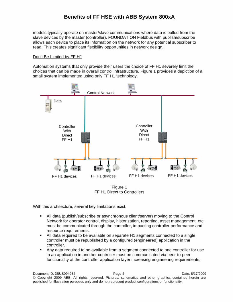
models typically operate on master/slave communications where data is polled from the slave devices by the master (controller). FOUNDATION Fieldbus with publish/subscribe allows each device to place its information on the network for any potential subscriber to read. This creates significant flexibility opportunities in network design. Don’t Be Limited by FF H1 Automation systems that only provide their users the choice of FF H1 severely limit the choices that can be made in overall control infrastructure. Figure 1 provides a depiction of a small system implemented using only FF H1 technology.
Figure 1 FF H1 Direct to Controllers
With this architecture, several key limitations exist:
All data (publish/subscribe or asynchronous client/server) moving to the Control Network for operator control, display, historization, reporting, asset management, etc. must be communicated through the controller, impacting controller performance and resource requirements.
All data required to be available on separate H1 segments connected to a single controller must be republished by a configured (engineered) application in the controller.
Any data required to be available from a segment connected to one controller for use in an application in another controller must be communicated via peer-to-peer functionality at the controller application layer increasing engineering requirements,
Data
Control Network
FF H1 devices FF H1 devices
Controller With
Direct FF H1
FF H1 devices FF H1 devices
Controller With
Direct FF H1
Benefits of FF HSE with ABB System 800xA
Document ID: 3BUS094954 Page 5 Date: 8/17/2009 © Copyright 2009 ABB. All rights reserved. Pictures, schematics and other graphics contained herein are published for illustration purposes only and do not represent product configurations or functionality.
impacting controller performance and resource requirements, and increasing control network traffic and performance.
When peer-to-peer communication must be avoided, more than one FF H1 segment from more than one controller must be run into the same geographic plant area to directly connect individual devices to individual controllers; increasing wiring and communication module costs. In some rare instances where the same information (measurement) is required and peer-to-peer cannot be used, two devices must be installed on the separate segments with the associated costs for the extra device and process connection.
Controller hardware may need to be distributed widely throughout the facility to support localized FF H1 distance limitations (1900m for combined H1 trunk and spurs) impacting initial project implementation costs (larger cabinets for controllers than linking devices and potential cabinet environmental conditioning … the linking device operating temperature tolerance is up to 55°C). Lifecycle maintenance costs may increase due to maintenance resource time moving around remote locations to service controllers versus working from a centralized equipment area.
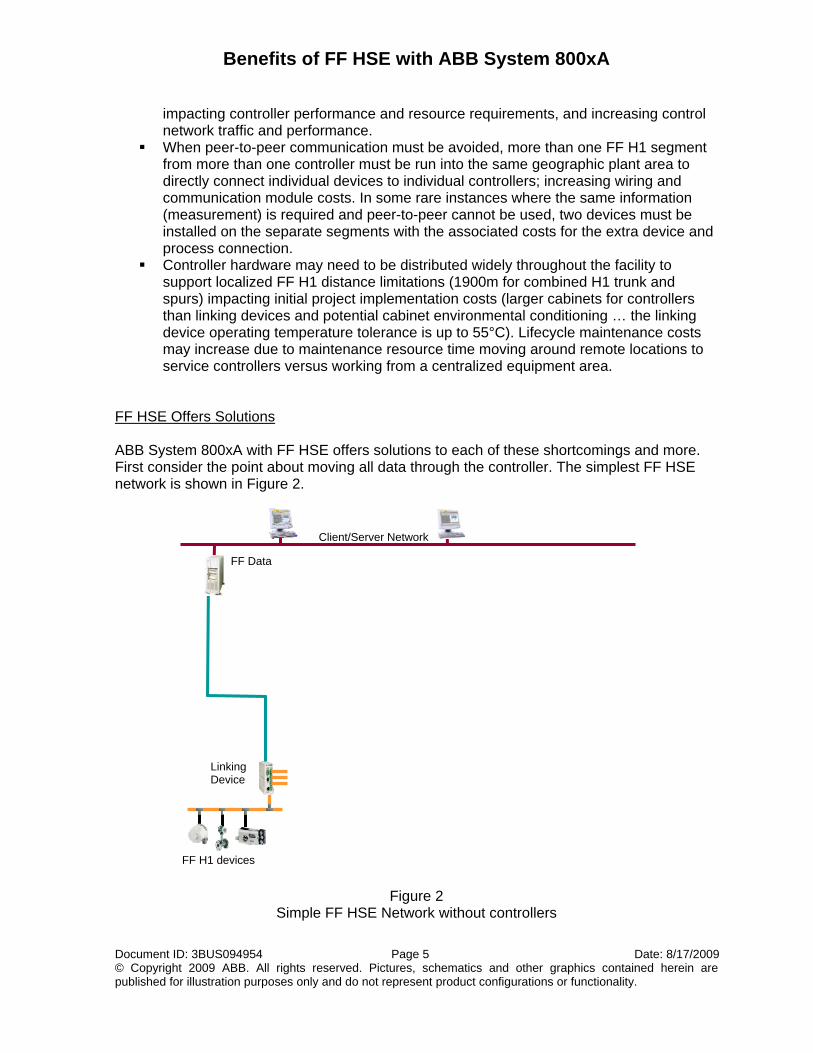
FF HSE Offers Solutions ABB System 800xA with FF HSE offers solutions to each of these shortcomings and more. First consider the point about moving all data through the controller. The simplest FF HSE network is shown in Figure 2.
Figure 2 Simple FF HSE Network without controllers
FF H1 devices
FF Data
Client/Server Network
Linking Device
Benefits of FF HSE with ABB System 800xA
Document ID: 3BUS094954 Page 6 Date: 8/17/2009 © Copyright 2009 ABB. All rights reserved. Pictures, schematics and other graphics contained herein are published for illustration purposes only and do not represent product configurations or functionality.
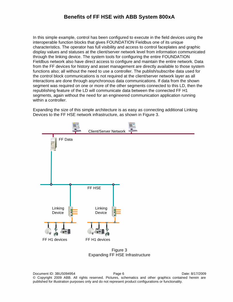
In this simple example, control has been configured to execute in the field devices using the interoperable function blocks that gives FOUNDATION Fieldbus one of its unique characteristics. The operator has full visibility and access to control faceplates and graphic display values and statuses at the client/server network level from information communicated through the linking device. The system tools for configuring the entire FOUNDATION Fieldbus network also have direct access to configure and maintain the entire network. Data from the FF devices for history and asset management are directly available to those system functions also; all without the need to use a controller. The publish/subscribe data used for the control block communications is not required at the client/server network layer as all interactions are done through asynchronous data communications. If data from the shown segment was required on one or more of the other segments connected to this LD, then the republishing feature of the LD will communicate data between the connected FF H1 segments, again without the need for an engineered communication application running within a controller. Expanding the size of this simple architecture is as easy as connecting additional Linking Devices to the FF HSE network infrastructure, as shown in Figure 3.
Figure 3 Expanding FF HSE Infrastructure
FF H1 devices FF H1 devices
FF Data
Client/Server Network
FF HSE
Linking Device
Linking Device
Benefits of FF HSE with ABB System 800xA
Document ID: 3BUS094954 Page 7 Date: 8/17/2009 © Copyright 2009 ABB. All rights reserved. Pictures, schematics and other graphics contained herein are published for illustration purposes only and do not represent product configurations or functionality.
The network shown in Figure 3 has all of the same features and functions described above. Additionally, we can also now pass data back and forth between the Linking Devices and their connected H1 segments with republish functionality provided by FF HSE. It would be a rare instance where closed loop PID control would be executed between devices on separate segments, but it may be important for values and statuses needed for complex interlock logic. Such data transfer is done automatically with the FF publish/subscribe features without the need for logic to be engineered within controllers to move data across FF H1 segments within a controller or move data between controllers with peer-to-peer engineered applications. Figure 3 also provides the basis to demonstrate geographic distribution of small clusters of FF H1 segments rather than being bound to controllers and controller application functionality. The FF HSE network can be widely distributed throughout the facility with only the Link Devices needing to be located in proximity to the actual field connection points. One of the earliest reasons for adopting FF was to eliminate wiring. If the FF H1 segments all originate in one central location from the controllers, then there will still be a large number of home run wiring paths to connect the controllers and the field. Using FF HSE replaces those long, individual home runs with a distributed network, further reducing the capital installed cost associated with labor for pulling wiring. By pushing the FF H1 connections as far as possible into the field using linking devices, the result is also much shorter FF H1 wiring. In many facilities, this can become an extremely important benefit when electrical interference might develop on the networks if long wiring runs were required. The FF HSE network can be installed using fiber optic media that is not affected by electrical interference and then using short FF H1 segments further reduces the potential impact of interference on plant operations. Using FF HSE With Controllers These two examples demonstrate a specific point; that FF HSE could be implemented without the need for controllers. It would be rare for an actual plant to build such an architecture. But these examples lay the groundwork to show that controllers and the resources they bring to the final control design do not need to be wasted on the movement of data from the FF H1 segments to the various end users (operators for display and control, engineers for configuration and asset management, business systems for history and reporting) found throughout the plant and enterprise. Figure 4, below, now introduces the more realistic scenario of using a controller as part of the complete automation design.
Benefits of FF HSE with ABB System 800xA
Document ID: 3BUS094954 Page 8 Date: 8/17/2009 © Copyright 2009 ABB. All rights reserved. Pictures, schematics and other graphics contained herein are published for illustration purposes only and do not represent product configurations or functionality.
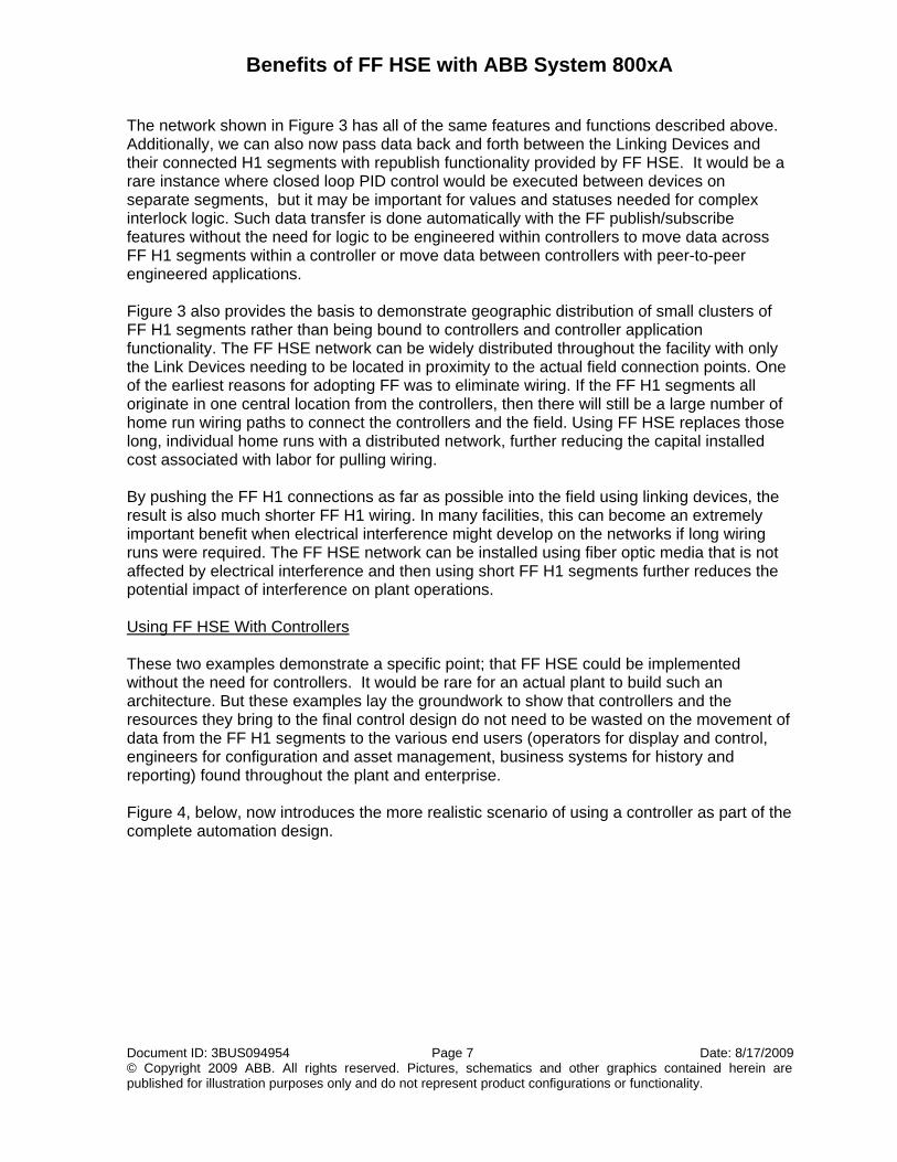
Figure 4 FF HSE network connect to AC 800M Controller
Most control implementations will include at least one controller. In Figure 4, all of the features discussed as part of Figure 3 still apply. All data moved to the client/server network is still done without passing that data through the AC 800M controller. The distribution of segments can still be done geographically, with savings achieved by eliminating long home runs for each of the FF H1 segments. Savings also result from not needing to provide larger, environmentally controlled enclosures for controller hardware if it is distributed to the field. The AC 800M controller uses FF HSE communication modules, CI860’s, to connect directly to the FF HSE network to send and receive publish/subscribe data from FF H1 devices (see Note 1 regarding acyclic data). The controller can be located in a centralized, environmentally friendly location, keeping both initial capital costs and longer term lifecycle costs for controller maintenance to a minimum. Only the data needed by the controller is actually brought into the controller. This limits the resources required by the controller to deal with FF control (smaller controllers) or provides capacity to increase the number of applications one controller can manage (fewer controllers in the project). Either benefit delivers on a lower capital cost for the project.
FF H1 devices
AC800M with CI860
FF H1 devices
OPC Server FF OPC Server AC800M
Client/Server Network
FF HSE
Linking Device
Linking Device
Benefits of FF HSE with ABB System 800xA
Document ID: 3BUS094954 Page 9 Date: 8/17/2009 © Copyright 2009 ABB. All rights reserved. Pictures, schematics and other graphics contained herein are published for illustration purposes only and do not represent product configurations or functionality.
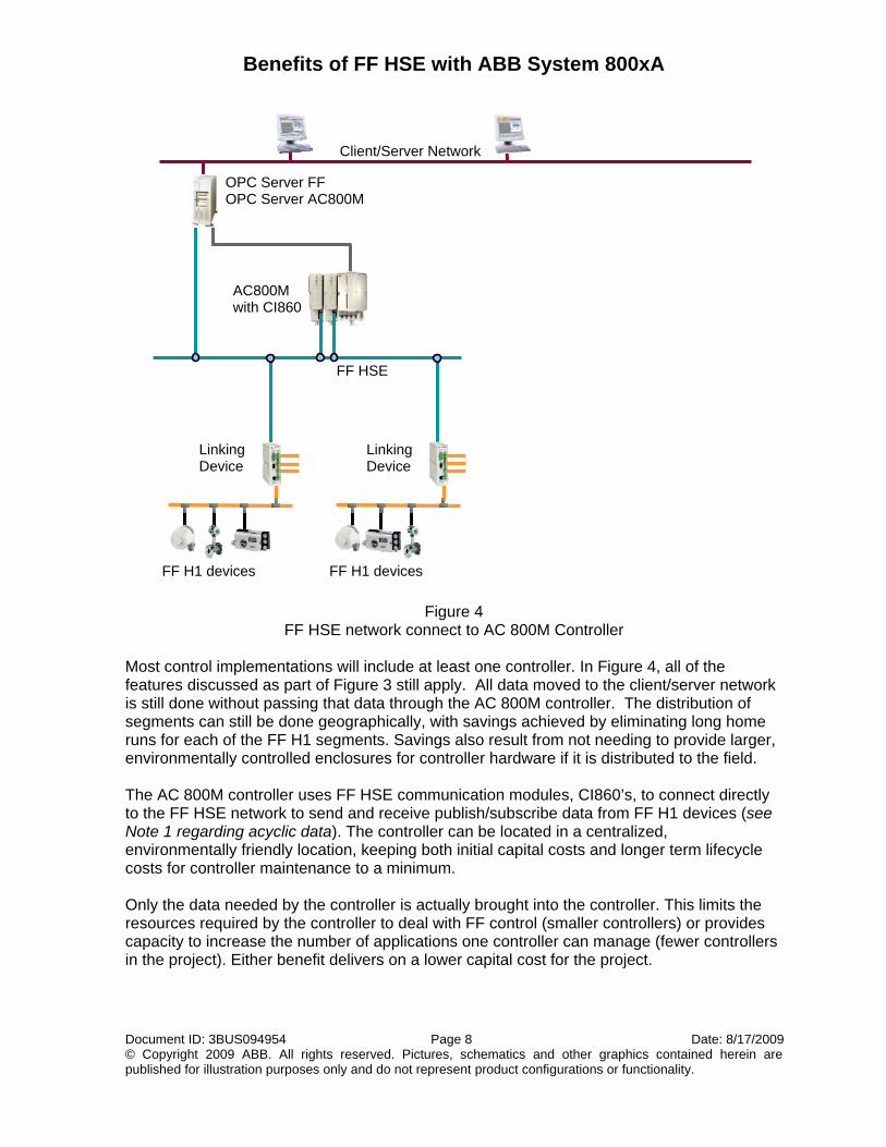
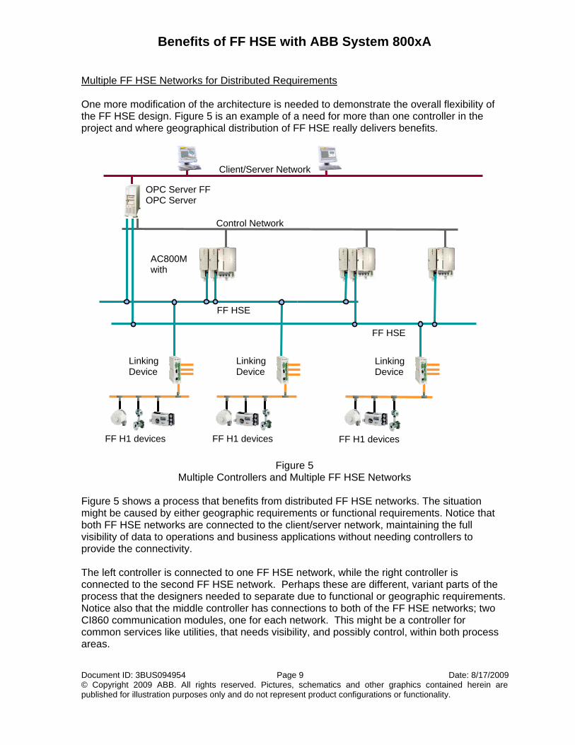
Multiple FF HSE Networks for Distributed Requirements One more modification of the architecture is needed to demonstrate the overall flexibility of the FF HSE design. Figure 5 is an example of a need for more than one controller in the project and where geographical distribution of FF HSE really delivers benefits.
Figure 5 Multiple Controllers and Multiple FF HSE Networks
Figure 5 shows a process that benefits from distributed FF HSE networks. The situation might be caused by either geographic requirements or functional requirements. Notice that both FF HSE networks are connected to the client/server network, maintaining the full visibility of data to operations and business applications without needing controllers to provide the connectivity. The left controller is connected to one FF HSE network, while the right controller is connected to the second FF HSE network. Perhaps these are different, variant parts of the process that the designers needed to separate due to functional or geographic requirements. Notice also that the middle controller has connections to both of the FF HSE networks; two CI860 communication modules, one for each network. This might be a controller for common services like utilities, that needs visibility, and possibly control, within both process areas.
FF H1 devices FF H1 devices
Linking Device
AC800M with
FF HSE
FF H1 devices
Control Network
OPC Server FF OPC Server
Client/Server Network
FF HSE
Linking Device
Linking Device
Benefits of FF HSE with ABB System 800xA
Document ID: 3BUS094954 Page 10 Date: 8/17/2009 © Copyright 2009 ABB. All rights reserved. Pictures, schematics and other graphics contained herein are published for illustration purposes only and do not represent product configurations or functionality.
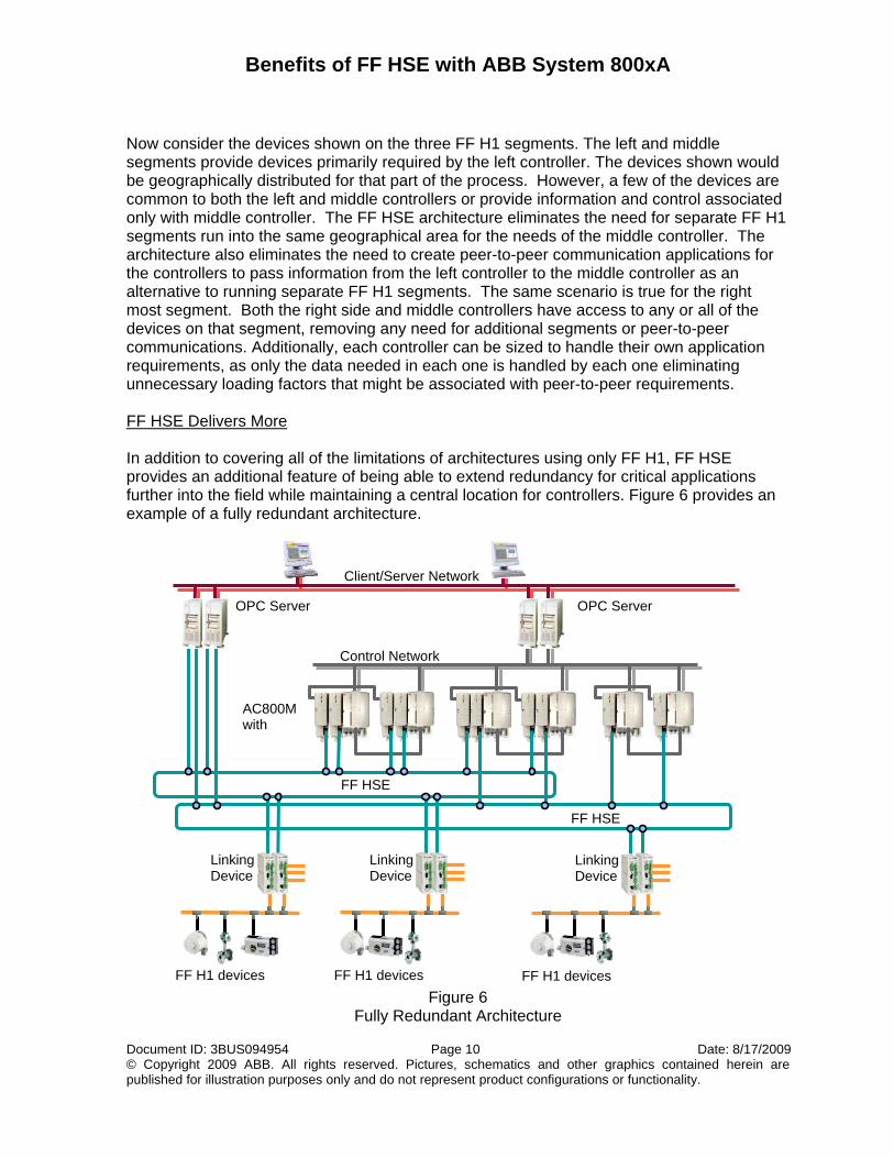
Now consider the devices shown on the three FF H1 segments. The left and middle segments provide devices primarily required by the left controller. The devices shown would be geographically distributed for that part of the process. However, a few of the devices are common to both the left and middle controllers or provide information and control associated only with middle controller. The FF HSE architecture eliminates the need for separate FF H1 segments run into the same geographical area for the needs of the middle controller. The architecture also eliminates the need to create peer-to-peer communication applications for the controllers to pass information from the left controller to the middle controller as an alternative to running separate FF H1 segments. The same scenario is true for the right most segment. Both the right side and middle controllers have access to any or all of the devices on that segment, removing any need for additional segments or peer-to-peer communications. Additionally, each controller can be sized to handle their own application requirements, as only the data needed in each one is handled by each one eliminating unnecessary loading factors that might be associated with peer-to-peer requirements. FF HSE Delivers More In addition to covering all of the limitations of architectures using only FF H1, FF HSE provides an additional feature of being able to extend redundancy for critical applications further into the field while maintaining a central location for controllers. Figure 6 provides an example of a fully redundant architecture.
Figure 6
Fully Redundant Architecture
FF H1 devices FF H1 devices
Linking Device
AC800M with
FF HSE
FF H1 devices
OPC Server
Control Network
OPC Server
Client/Server Network
FF HSE
Linking Device
Linking Device
Benefits of FF HSE with ABB System 800xA
Document ID: 3BUS094954 Page 11 Date: 8/17/2009 © Copyright 2009 ABB. All rights reserved. Pictures, schematics and other graphics contained herein are published for illustration purposes only and do not represent product configurations or functionality.
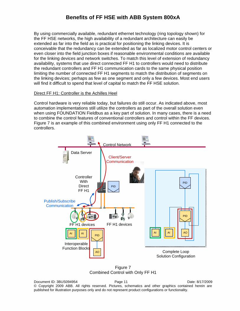
By using commercially available, redundant ethernet technology (ring topology shown) for the FF HSE networks, the high availability of a redundant architecture can easily be extended as far into the field as is practical for positioning the linking devices. It is conceivable that the redundancy can be extended as far as localized motor control centers or even closer into the field junction boxes if reasonable environmental conditions are available for the linking devices and network switches. To match this level of extension of redundancy availability, systems that use direct connected FF H1 to controllers would need to distribute the redundant controllers and FF H1 communication cards to the same physical position limiting the number of connected FF H1 segments to match the distribution of segments on the linking devices; perhaps as few as one segment and only a few devices. Most end users will find it difficult to spend that level of capital to match the FF HSE solution. Direct FF H1: Controller is the Achilles Heel Control hardware is very reliable today, but failures do still occur. As indicated above, most automation implementations still utilize the controllers as part of the overall solution even when using FOUNDATION Fieldbus as a key part of solution. In many cases, there is a need to combine the control features of conventional controllers and control within the FF devices. Figure 7 is an example of this combined environment using only FF H1 connected to the controllers.
Figure 7
Combined Control with Only FF H1
Data Server
Control Network
FF H1 devices FF H1 devices
Controller With
Direct FF H1
Publish/Subscribe Communication
Client/Server Communication
PID
AO
AI AI
PID
Interoperable Function Blocks
Complete Loop Solution Configuration
AO AI
PID
PID
AI
Benefits of FF HSE with ABB System 800xA
Document ID: 3BUS094954 Page 12 Date: 8/17/2009 © Copyright 2009 ABB. All rights reserved. Pictures, schematics and other graphics contained herein are published for illustration purposes only and do not represent product configurations or functionality.
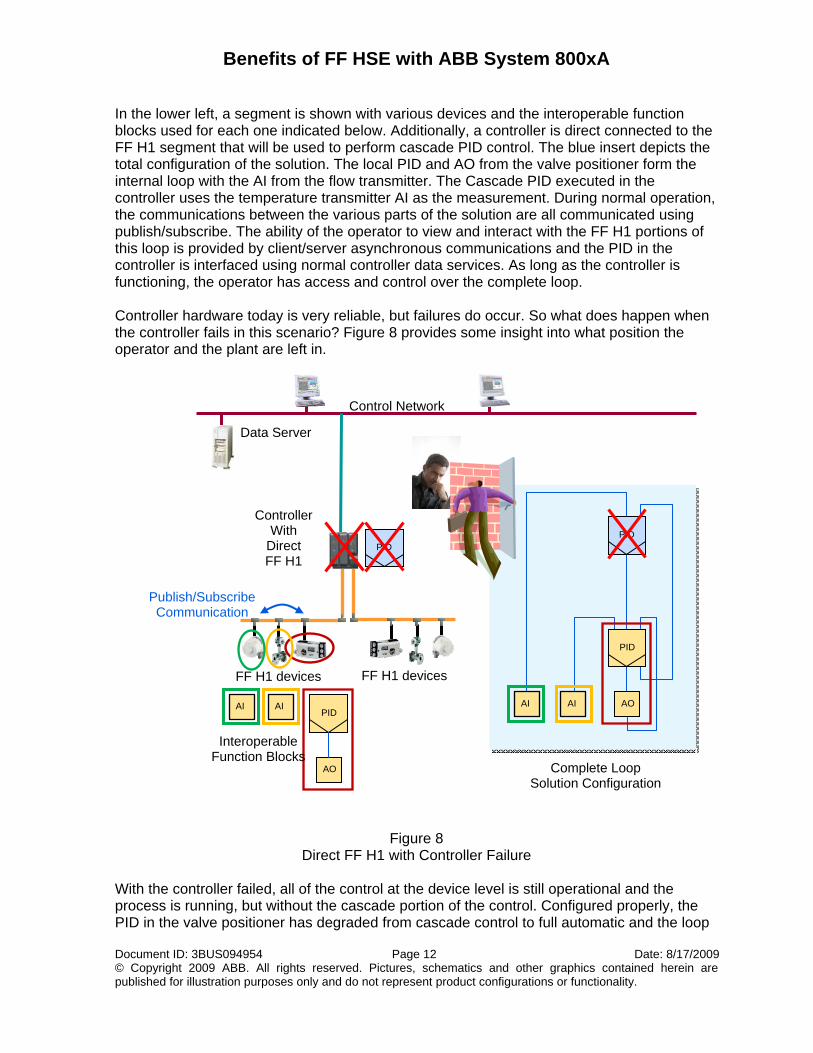
In the lower left, a segment is shown with various devices and the interoperable function blocks used for each one indicated below. Additionally, a controller is direct connected to the FF H1 segment that will be used to perform cascade PID control. The blue insert depicts the total configuration of the solution. The local PID and AO from the valve positioner form the internal loop with the AI from the flow transmitter. The Cascade PID executed in the controller uses the temperature transmitter AI as the measurement. During normal operation, the communications between the various parts of the solution are all communicated using publish/subscribe. The ability of the operator to view and interact with the FF H1 portions of this loop is provided by client/server asynchronous communications and the PID in the controller is interfaced using normal controller data services. As long as the controller is functioning, the operator has access and control over the complete loop. Controller hardware today is very reliable, but failures do occur. So what does happen when the controller fails in this scenario? Figure 8 provides some insight into what position the operator and the plant are left in.
Figure 8 Direct FF H1 with Controller Failure
With the controller failed, all of the control at the device level is still operational and the process is running, but without the cascade portion of the control. Configured properly, the PID in the valve positioner has degraded from cascade control to full automatic and the loop
PID
Data Server
Control Network
FF H1 devices FF H1 devices
Controller With
Direct FF H1
Publish/Subscribe Communication
PID
AO
AI AI
Interoperable Function Blocks
Complete Loop Solution Configuration
AO AI
PID
PID
AI
Benefits of FF HSE with ABB System 800xA
Document ID: 3BUS094954 Page 13 Date: 8/17/2009 © Copyright 2009 ABB. All rights reserved. Pictures, schematics and other graphics contained herein are published for illustration purposes only and do not represent product configurations or functionality.
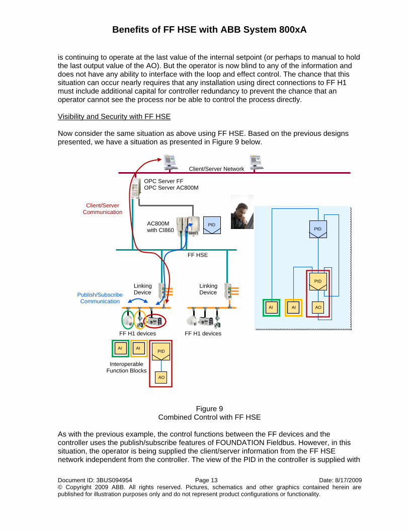
is continuing to operate at the last value of the internal setpoint (or perhaps to manual to hold the last output value of the AO). But the operator is now blind to any of the information and does not have any ability to interface with the loop and effect control. The chance that this situation can occur nearly requires that any installation using direct connections to FF H1 must include additional capital for controller redundancy to prevent the chance that an operator cannot see the process nor be able to control the process directly. Visibility and Security with FF HSE Now consider the same situation as above using FF HSE. Based on the previous designs presented, we have a situation as presented in Figure 9 below.
Figure 9 Combined Control with FF HSE
As with the previous example, the control functions between the FF devices and the controller uses the publish/subscribe features of FOUNDATION Fieldbus. However, in this situation, the operator is being supplied the client/server information from the FF HSE network independent from the controller. The view of the PID in the controller is supplied with
FF H1 devices
AC800M with CI860
FF H1 devices
OPC Server FF OPC Server AC800M
Client/Server Network
FF HSE
Linking Device
Linking Device
PID
AI
PID
AO
Publish/Subscribe Communication
Client/Server Communication
PID
AO
AI
AI
Interoperable Function Blocks
AI
PID
Benefits of FF HSE with ABB System 800xA
Document ID: 3BUS094954 Page 14 Date: 8/17/2009 © Copyright 2009 ABB. All rights reserved. Pictures, schematics and other graphics contained herein are published for illustration purposes only and do not represent product configurations or functionality.
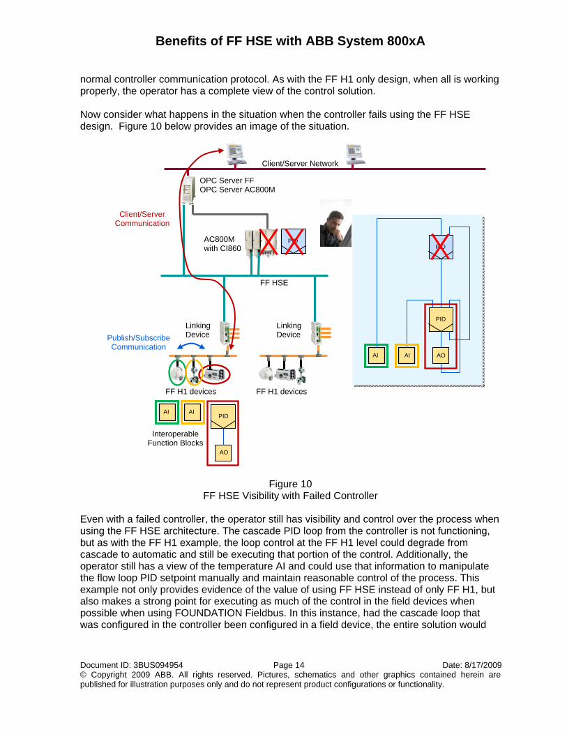
normal controller communication protocol. As with the FF H1 only design, when all is working properly, the operator has a complete view of the control solution. Now consider what happens in the situation when the controller fails using the FF HSE design. Figure 10 below provides an image of the situation.
Figure 10 FF HSE Visibility with Failed Controller
Even with a failed controller, the operator still has visibility and control over the process when using the FF HSE architecture. The cascade PID loop from the controller is not functioning, but as with the FF H1 example, the loop control at the FF H1 level could degrade from cascade to automatic and still be executing that portion of the control. Additionally, the operator still has a view of the temperature AI and could use that information to manipulate the flow loop PID setpoint manually and maintain reasonable control of the process. This example not only provides evidence of the value of using FF HSE instead of only FF H1, but also makes a strong point for executing as much of the control in the field devices when possible when using FOUNDATION Fieldbus. In this instance, had the cascade loop that was configured in the controller been configured in a field device, the entire solution would
FF H1 devices
AC800M with CI860
FF H1 devices
OPC Server FF OPC Server AC800M
Client/Server Network
FF HSE
Linking Device
Linking Device
PID
Publish/Subscribe Communication
Client/Server Communication
Interoperable Function Blocks
PID
AO
PID
AI AI
PID
AO
AI AI
Benefits of FF HSE with ABB System 800xA
Document ID: 3BUS094954 Page 15 Date: 8/17/2009 © Copyright 2009 ABB. All rights reserved. Pictures, schematics and other graphics contained herein are published for illustration purposes only and do not represent product configurations or functionality.
still be active without the controller and the operator would have full visibility and full control capability over the solution. As with the FF H1 only scenario, an argument can be made that a failure of the single linking device will also leave the operator blind to the control that remains running. Redundancy will once again play a role in minimizing the risk of such a failure. Recall that the FF H1 scenario had to use redundant controllers to improve the availability and minimize the risk. For the FF HSE scenario, the risk reduction is achieved with redundant linking devices at a much lower capital cost. And going back to other portions of this discussion, those linking devices may be done remotely from the central control area further reducing the capital impact of longer FF H1 home run wiring or possible costs involved with remote installation of controllers. FF HSE: Looking to the Future FF HSE is a network infrastructure with a great deal of future potential. The ability to use the same interoperable function block features for devices directly connected to this network as well as the lower level FF H1 segments provides many opportunities. Already there are efforts underway to create standards for connecting data-intensive conventional 4-20 mA (HART) I/O remotely to controllers utilizing the high speed ethernet backbone that underlies FF HSE. One can speculate that at some point we will see other data-intensive devices and applications such as analyzers, variable frequency drives, and gateways to other control networks that will be designed to directly connect to FF HSE. Several years have now passed since the demonstration project that identified the use of Flexible Function Blocks as a means of using FF HSE based controller devices to perform complex logic directly as part of a FOUNDATION Fieldbus architecture. The technology is simply waiting on the marketplace to find needs for performing advanced control functions or highly complex sequence/batch control directly within the structures provided by FOUNDATION Fieldbus. Wireless is already a high interest subject throughout the automation industry. Wireless FF devices may not be available today, but wireless FF HSE networking is available. The high speed ethernet infrastructure can use wireless routers/access points now, if the system owner is so inclined. Using wireless networking and remote location of the linking devices close to the process would eliminate nearly all wire or fiber optic cable cost and labor from the project except for the short instrument spur wiring far into the field. When the needs arise, only those systems that use FF HSE as a native part of their infrastructure will truly provide their system owners with benefits that can be realized as the need is created. Systems that natively use only FF H1, will need to develop the FF HSE connectivity and find ways to incorporate the features into an FF H1 centric solution. Time and opportunity will surely be lost waiting on a solution that other will already be exploiting.
Benefits of FF HSE with ABB System 800xA
Document ID: 3BUS094954 Page 16 Date: 8/17/2009 © Copyright 2009 ABB. All rights reserved. Pictures, schematics and other graphics contained herein are published for illustration purposes only and do not represent product configurations or functionality.
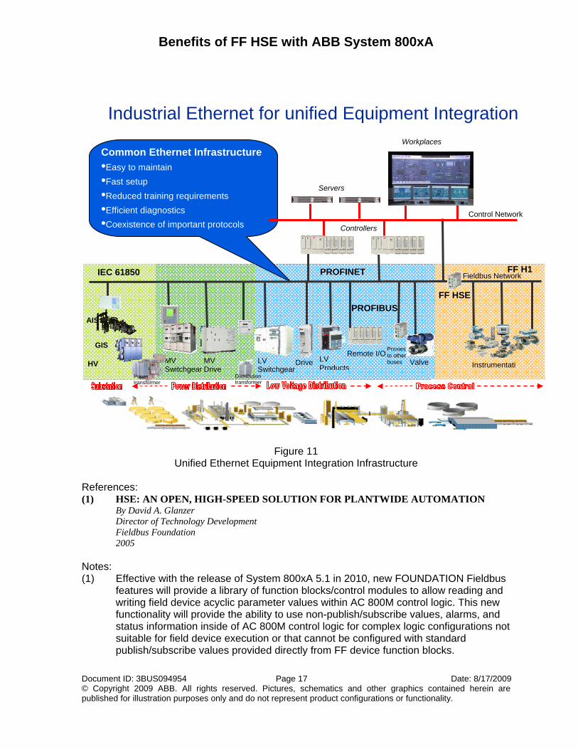
FF HSE, a Complete, More Cost Effective Solution For Today and Tomorrow As discussed earlier, there are a variety of shortcomings to using an FF H1 only design for implementing FOUNDATION Fieldbus projects. The discussion above has addressed each of the limitations and shown how using FF HSE provides solutions to each of those limitations. Additionally, when using control in the field, using FF HSE provides a more safe and robust solution to managing the overall plant control in those low probability, but important situations when controller hardware does fail. Using FF HSE provides the end user an option to reduce the capital costs associated with a near absolute need for controller redundancy when using the FF H1 only solution by shifting the redundancy needs to lower cost linking device hardware. Further project capital reductions can be achieved with FF HSE when remotely locating linking devices close to the process areas. The costs associated with installing and maintaining either a single or redundant FF HSE network architecture is far cheaper than pulling each of the FF H1 home runs back to a central control area or remotely locating controllers into the process areas. The capital reductions could be significant when it might be necessary to significantly increase the number of controllers to deliver the same geographical distribution of FF H1 as is available by using linking devices. Finally, the potential exists for devices to be direct connected to an FF HSE backbone. These devices will be significantly more sophisticated than today’s FF H1 devices and will have high data demands that will be inappropriate for connecting to FF H1 segments. A system that only uses FF H1 today is not prepared to easily allow the end user to take immediate advantage of these beneficial extensions to the FOUNDATION Fieldbus environment. By comparison, ABB System 800xA with its native implementation of FF HSE, is one system that is already prepared to deliver on the usage and capital benefits compared to the FF H1 solutions today, and provides the infrastructure to quickly benefit from the advances that will likely come in the future. FF HSE: One Part of a Unified Equipment & Electrical Management Infrastructure One final point about the future: Implementing a networked-style infrastructure now using FF HSE provides the overall ethernet backbone your facility can benefit from moving forward with other advancing subsystem technologies. Many of the classical serial networks like MODBUS and Devicenet now support an ethernet infrastructure in their MODBUS/TCP and Ethernet/IP formats. Profibus now supports ethernet infrastructure with its PROFINET implementation. The ever expanding environment of electrical subsystem integration to link the traditional realms of process control to the electrification centers within a facility is now available with the new IEC 61850 communication standard for electrical control devices. This helps optimize the utilization of electrical energy based on process conditions. It too utilizes an ethernet infrastructure. One ethernet backbone architecture will allow process owners to choose the ideal communication protocols they need to extract the most in cost reductions and optimization benefits from their facilities. Implementing an FF HSE architecture today provides the basis to use any of these other environments on the same plant-wide backbone at any time into the future. Please see Figure 11 below for a visual representation of this unified infrastructure.
Benefits of FF HSE with ABB System 800xA
Document ID: 3BUS094954 Page 17 Date: 8/17/2009 © Copyright 2009 ABB. All rights reserved. Pictures, schematics and other graphics contained herein are published for illustration purposes only and do not represent product configurations or functionality.
Figure 11 Unified Ethernet Equipment Integration Infrastructure
References: (1) HSE: AN OPEN, HIGH-SPEED SOLUTION FOR PLANTWIDE AUTOMATION
By David A. Glanzer Director of Technology Development Fieldbus Foundation 2005
Notes: (1) Effective with the release of System 800xA 5.1 in 2010, new FOUNDATION Fieldbus
features will provide a library of function blocks/control modules to allow reading and writing field device acyclic parameter values within AC 800M control logic. This new functionality will provide the ability to use non-publish/subscribe values, alarms, and status information inside of AC 800M control logic for complex logic configurations not suitable for field device execution or that cannot be configured with standard publish/subscribe values provided directly from FF device function blocks.
Common Ethernet Infrastructure •Easy to maintain •Fast setup •Reduced training requirements •Efficient diagnostics •Coexistence of important protocols
Industrial Ethernet for unified Equipment Integration
Proxies to other buses
FF H1 Fieldbus Network
Controllers
Servers
Workplaces
MV Drive
MV Switchgear
LV Switchgear
LV Products
DriveRemote I/O
Instrumentati
Control Network
HV Valve
GIS
AIS
Distribution transformer
Power transformer
FF HSE
IEC 61850 PROFINET
PROFIBUS
Document ID: 3BUS094954 Date: 8/17/2009 © Copyright 2009 ABB. All rights reserved. Pictures, schematics and other graphics contained herein are published for illustration purposes only and do not represent product configurations or functionality.