bending roll machine 8344 - nosstecnosstec.com/static/files/8344nt_en_r4.pdf · operating...
TRANSCRIPT
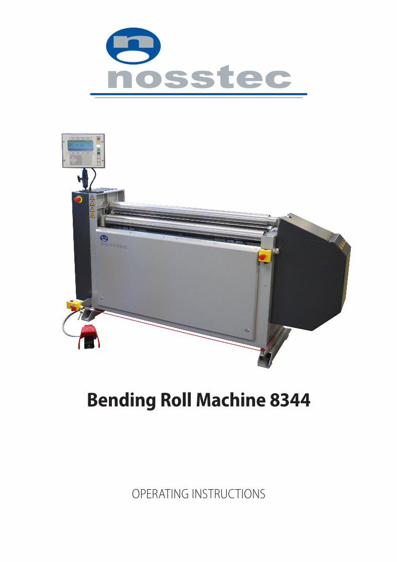
Bending Roll Machine 8344
Operating instructiOns


8344 English, rev 4 3
Table of conTenTs
Main components . . . . . . . . . . . . . . . . . . . . . . . . . . . . . . . . . . . . . . . . . . . . . . . . . . . . . . . . . . . . 4Installation . . . . . . . . . . . . . . . . . . . . . . . . . . . . . . . . . . . . . . . . . . . . . . . . . . . . . . . . . . . . . . . . . . . . 5Safety . . . . . . . . . . . . . . . . . . . . . . . . . . . . . . . . . . . . . . . . . . . . . . . . . . . . . . . . . . . . . . . . . . . . . . . . . . 7Operation . . . . . . . . . . . . . . . . . . . . . . . . . . . . . . . . . . . . . . . . . . . . . . . . . . . . . . . . . . . . . . . . . . . 12Programming . . . . . . . . . . . . . . . . . . . . . . . . . . . . . . . . . . . . . . . . . . . . . . . . . . . . . . . . . . . . . . . 28Service and maintenance . . . . . . . . . . . . . . . . . . . . . . . . . . . . . . . . . . . . . . . . . . . . . . . . . . 30Lubrication / Grease chart . . . . . . . . . . . . . . . . . . . . . . . . . . . . . . . . . . . . . . . . . . . . . . . . . 32Fuses and motor protection . . . . . . . . . . . . . . . . . . . . . . . . . . . . . . . . . . . . . . . . . . . . . . . 34Technical data . . . . . . . . . . . . . . . . . . . . . . . . . . . . . . . . . . . . . . . . . . . . . . . . . . . . . . . . . . . . . . 35Machine plates and stickers . . . . . . . . . . . . . . . . . . . . . . . . . . . . . . . . . . . . . . . . . . . . . . . 36Declaration of conformity. . . . . . . . . . . . . . . . . . . . . . . . . . . . . . . . . . . . . . . . . . . . . . . . . . 37Contact information . . . . . . . . . . . . . . . . . . . . . . . . . . . . . . . . . . . . . . . . . . . . . . . . . See back
Note: We reserve the right to alter specifications without prior notice.
For copyright reasons all reproduction and copying of the texts, tables and illustrations within this manual is prohibited without written permission from Nosstec AB.
Operating instructiOns 8344
4 2013-04-19
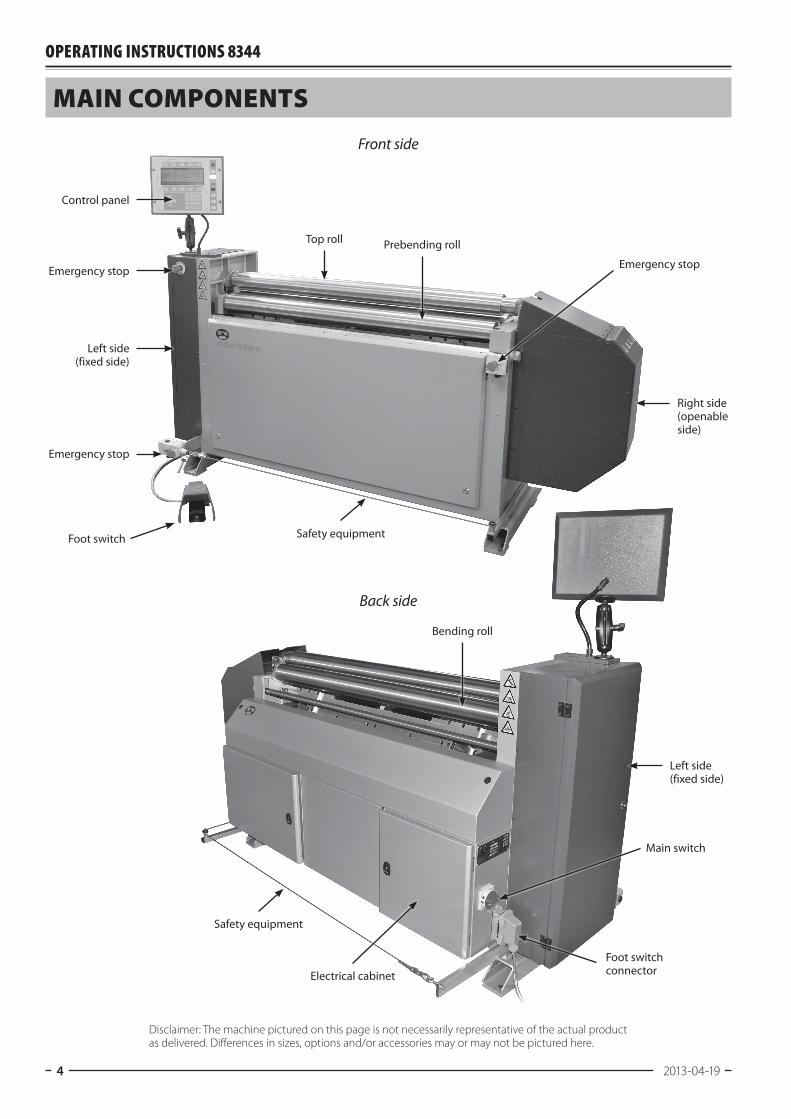
Emergency stop
Emergency stop
Emergency stop
Control panel
Top roll Prebending roll
Bending roll
Safety equipment
Safety equipment
Electrical cabinet
Main coMponenTs
Front side
Back side
Disclaimer: The machine pictured on this page is not necessarily representative of the actual product as delivered. Differences in sizes, options and/or accessories may or may not be pictured here.
Foot switch
Foot switch connector
Main switch
Left side (fixed side)
Right side (openable side)
Left side (fixed side)
8344 English, rev 4 5
insTallaTion
InstallationThe machine must be placed on firm ground e.g. cemented floor. The ground must be level in order to avoid tensions in the machine when fixing it to the floor. The machine must be bolted to the floor with 4pcs expansion shell bolts diameter 16 mm.Check that the motor is branched to the right voltage.
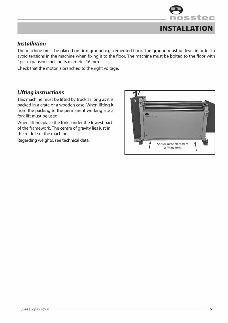
Lifting instructionsThis machine must be lifted by truck as long as it is packed in a crate or a wooden case. When lifting it from the packing to the permanent working site a fork lift must be used.When lifting, place the forks under the lowest part of the framework. The centre of gravity lies just in the middle of the machine.Regarding weights: see technical data.
Approximate placement of lifting forks

Operating instructiOns 8344
6 2013-04-19
insTallaTion
Electrical connectionAlways check the sign on the machine, or the wiring diagram (located in the door to the electrical cabinet), that explains the electrical data for the specific machine. Follow local regulations for electrical connectionAuthorised personnel only to carry out connecting and repair work to the electrical equipment of the machine!
Foot switchConnect footpedal to the multiconnector. The machine cannot be opera-ted if this is not connected.
Protective equipmentCheck that all protective and emergency functions are mounted and in working order.
StartTurn the main switch, situated on the back right side (seen from the back) of the machine, to position 1. When not in use, the machine should be secured from unauthorized use with a padlock that locks the main switch in the off position.
8344 English, rev 4 7
safeTy
GeneralThis bending roll machine is designed with a view to eliminating personal injuries provided that the in-structions in this manual are being followed.Only authorized and trained staff is allowed to use the machine. Read the whole instruction manual and make sure that you understand the contents before the machine is taken into use. It is important that you read the safety instructions below.
Keep the instruction manual of the machine in a safe placeThe instruction manual contains important information that besides the safety information also give im-portant information regarding operation, service, maintenance etc.
Safety instructions in connection with the installationThe machine must be bolted to the floor with 4 pcs expansion shell bolts diameter 16 mm. Electrical installation of the machine must be carried out by authorized staff.
Protective clothingImportant! Never use gloves when bending, as this considerably in-creases the risk of getting pinched between the rolls. For other handling of the workpieces use gloves. The operator must not carry belts, rings or necklaces.Working shoes with steel inserts must be used.Loose hanging clothes must not be used.If the operator has long hair, this must not hang loose.
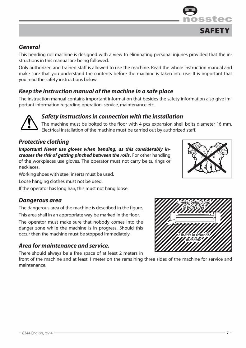
Dangerous areaThe dangerous area of the machine is described in the figure.This area shall in an appropriate way be marked in the floor.The operator must make sure that nobody comes into the danger zone while the machine is in progress. Should this occur then the machine must be stopped immediately.
Area for maintenance and service.There should always be a free space of at least 2 meters in front of the machine and at least 1 meter on the remaining three sides of the machine for service and maintenance.
1 meter behind and to both sides
2 meter in front of machine
Operating instructiOns 8344
8 2013-04-19
safeTy
Check that the environment around the machine is suitable• Do not expose the machine to rain.• Do not use the machine in wet or damp premises.• Check that the lighting of the premises is satisfactory.• The floor must be clean, dry and free from oil and grease spots.• Never use easily inflammable material close to the machine.• Dirty working sites increase the risk of accidents.
Main switchThe machine should be equipped with a padlock for the main switch, and the operator must take cau-tion to check the machine before powering it on that the padlock is secured and locked before removing it and switching the machine on.When leaving the machine for any length of time where it is not under supervision, the main switch should always be turned off and the padlock securely locking it to prevent unauthorized use.
ApplicationNever use the machine for material which is outside the capacity range of the machine. Check the machine plate and the section “Technical data”.
Before the machine is operated the following steps must be taken:Check that all safety devices function and that they are not damaged. Also check that moveable parts are not exposed to obstacles e.g. owing to incorrectly mounted guards or parts. Broken parts or safety com-ponents must be changed by authorized staff. Contact Nosstec in case spare parts are needed. The ma-chine has a 24 month applicable warranty from date of delivery. The warranty is only applicable as long as original spare parts are used.
Avoid unstable working positionsCheck that the operator always has a secure and stable working position.
Do not keep tools on the machineRemove all tools from the machine before it is operated.

8344 English, rev 4 9
safeTy
Danger zoneIn connection with production work check that no part of the body comes too close to the infeed side of the clamping rolls of the machine (see figure).Note: The infeed side may vary owing to the direction of rotation of the rolls.
Airborne noiseThe following noise level has been measured at the operator’s place:Equivalent noise level Leq, idle running 62 dB(A)Equivalent noise level Leq, operation 63 dB(A)
Falling work piecesThe work piece is ejected and can fall to the floor when it has been rolled. This means you should take care while working, especially in the case of large work pieces.If necessary, use a lift table, overhead crane or other lifting device.
Moving work piecesWhile the bending roll is working, the work piece moves up and down. Take care and do not stand too close to the work piece – there is a risk of injury to your torso, arms, legs or face. The machine is fast working, which means the move-ments are correspondingly fast.
Pinching risk of the workpieceNote that there is a pinching risk between the ends of the workpiece, see figure.
Pinching risk
While it is being rolled, the work piece may move forwards, backwards, up and down in the machine.
The work piece can exit the machine from the front or from the back.
Operating instructiOns 8344
10 2013-04-19
safeTy
Deburring of the workpieceBurrs and sharp edges must be removed from the workpiece before bending.
JammingIf for some reason the machine stops while bending a workpiece, proceed as follows:• Run the pinch roll and if possible also the bending roll.• Remove the workpiece. Identify the trouble reason. If the motor protection is released,
wait for some minutes before it is reset. The machine is then ready for use again.• If the trouble is mechanical or electrical: Cut the current and contact the supervisor.
Regular checkingDaily check the function of the foot switch as well as the condition of the electric cable of the foot switch.Also check that the emergency stop works. Carry also out the regular service, which is de scribed in the chapter Service and Maintenance in the instruction manual.
Modification of the machineAll conversion, modification or change of this machine is strictly forbidden with the exception of• Original spare parts• Optional equipment supplied by the manufacturer.
All repairs must be carried out by authorized staffThe machine and its electrical equipment has been made according to valid safety rules. All repairs must be carried out by trained and qualified staff. Only original spares must be used.
Cut the powerCut the current before touching live parts. This is done either by disconnecting the main switch of the machine or by disconnecting the voltage of the electrical cabinet. Note: Do not put the main switch or the safety switch of the machine out of operation. The main switch must be locked with a padlock when the machine is not in use (recommended during all repair and maintenance).

8344 English, rev 4 11
safeTy
Emergency stopThe machine has a number of safety switches and emergency stop devices:
• Thefootpedalhasanemergencystopfunction,whichyoucanactivatebypushing down very hard.
• Youcanactivate theemergencystopon the right sideof themachinebypressing it.
• Youcanactivatetheemergencystopontheleftsideofthemachinebypressingit.• Thesafetylineinthelowerpartoftherearofthemachineisactivatedbymovementorif it is
broken.
To reset the emergency stop, rotate the button anticlockwise, in the direction of the arrow.
Foot switchTo reset the stop function of the foot pedal, push down the button on the pedal side.
Safety lineTo reset the safety line, press the button on the safety switch at the end of the line. The machine cannot be restarted until the Reset key on the control panel has been pressed.
Important:The operator must know the location of all the stop and emergency stop functions and how to operate them.
All protective devices must be fitted and the transmission doors must be locked.
Reset button
Safety line
Emergency stop
Reset Emergency stop
Reset
Foot pedal
Main switch

Operating instructiOns 8344
12 2013-04-19
operaTion
Outline of control panel functions
The operating system is run from the control panel. The panel is logically designed to simplify operation.
Function keys Display Mode selector
KeypadArrow keys and ESC
Reset
Auto
Manual
Run
Program
8344 English, rev 4 13
operaTion
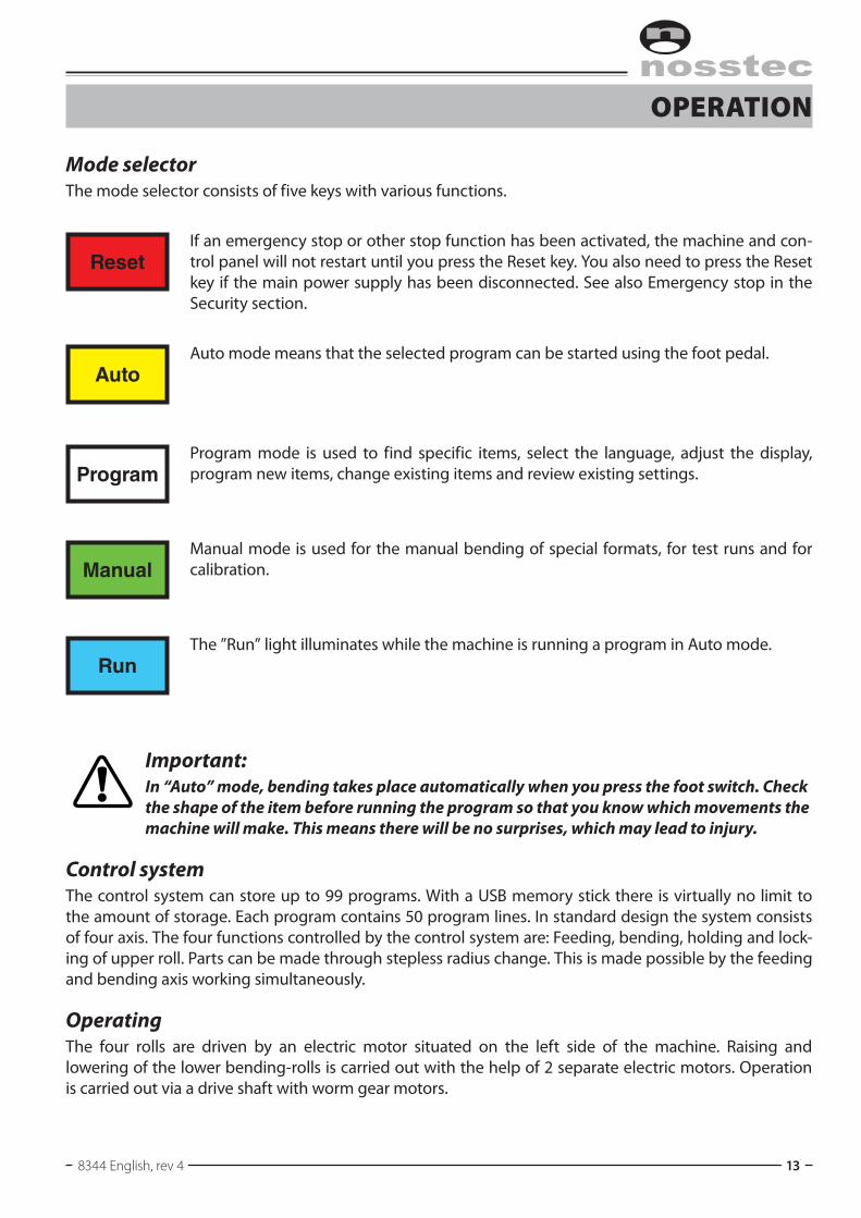
Mode selectorThe mode selector consists of five keys with various functions.
ResetIf an emergency stop or other stop function has been activated, the machine and con-trolpanelwillnotrestartuntilyoupresstheResetkey.YoualsoneedtopresstheResetkey if the main power supply has been disconnected. See also Emergency stop in the Security section.
AutoAuto mode means that the selected program can be started using the foot pedal.
ProgramProgram mode is used to find specific items, select the language, adjust the display, program new items, change existing items and review existing settings.
ManualManual mode is used for the manual bending of special formats, for test runs and for calibration.
RunThe ”Run” light illuminates while the machine is running a program in Auto mode.
Important:In “Auto” mode, bending takes place automatically when you press the foot switch. Check the shape of the item before running the program so that you know which movements the machine will make. This means there will be no surprises, which may lead to injury.
Control systemThe control system can store up to 99 programs. With a USB memory stick there is virtually no limit to the amount of storage. Each program contains 50 program lines. In standard design the system consists of four axis. The four functions controlled by the control system are: Feeding, bending, holding and lock-ing of upper roll. Parts can be made through stepless radius change. This is made possible by the feeding and bending axis working simultaneously.
OperatingThe four rolls are driven by an electric motor situated on the left side of the machine. Raising and lowering of the lower bending-rolls is carried out with the help of 2 separate electric motors. Operation is carried out via a drive shaft with worm gear motors.

Operating instructiOns 8344
14 2013-04-19
operaTion
Display windowThe display of the machine provides the ope-rator with the necessary information about the current operation and the settings. The display shows various screens depending on the cur-rent mode of the machine.
MarkerThe display contains a marker indicating where your input will go. The marker will illuminate the actual field or position in yellow colour.
Function keysAbove and below the display, there are two rows of five function keys. The keys have different functions depending on the current screen in the display. The top and bottom rows of the screen show the fun-ction of each button.
Arrow keys and EscThe arrow keys are used to move the cursor around the display.

8344 English, rev 4 15
operaTion
KeyboardThe keypad is used to enter numbers (and letters) at the location indicated by the marker.
Delete keyTo delete the value you have just entered or the text you have just typed.
Shift keyYoucanpressShift to switch to lettermode (seebe-low).
Enter keyPress Enter to confirm the value you have just entered.
Using lettersYoucanpressSHIFTtousethelettersshownonthenumberkeys.TotypeA,pressandholddownSHIFTandpressthenumberkey0.TotypeB, firstpressandreleaseSHIFTonce, thenpressSHIFTagainandholditdownwhilepressingthenumberkey0.SototypeC,pressandreleaseSHIFTtwice,thenpressSHIFTathirdtimeandholditdownwhilepressingthenumberkey0.Two special cases are comma and space, which are produced with the dot key (see example below).
Example: 0 = 0 SHIFT + . = , (comma) SHIFT+0 =A SHIFT+SHIFT + . = (space) SHIFTSHIFT + 0 = B SHIFTSHIFTSHIFT + 0 = C
WhereSHIFTisunderlined,pressandholddownthekeywhilepressingtherelevantletterkey.
PasswordThe keyboard can be protected with a 5-digit code that the machine supervisor receives from Nosstec. The machine can otherwise only be run without any program changes unless the code is entered.
Delete key
Shift key
Enter key
Operating instructiOns 8344
16 2013-04-19
operaTion
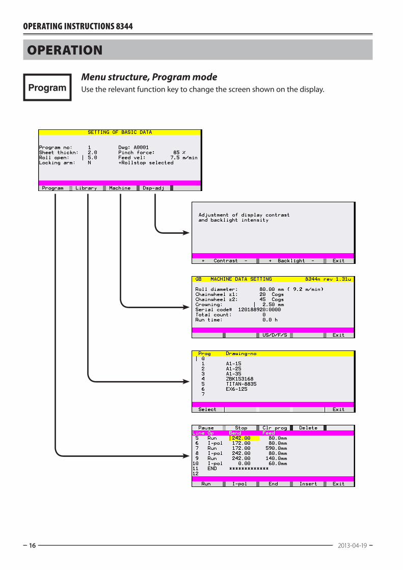
ProgramMenu structure, Program modeUse the relevant function key to change the screen shown on the display.
8344 English, rev 4 17
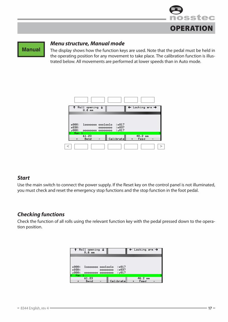
operaTion
ManualMenu structure, Manual modeThe display shows how the function keys are used. Note that the pedal must be held in the operating position for any movement to take place. The calibration function is illus-trated below. All movements are performed at lower speeds than in Auto mode.
StartUse the main switch to connect the power supply. If the Reset key on the control panel is not illuminated, you must check and reset the emergency stop functions and the stop function in the foot pedal.
Checking functionsCheck the function of all rolls using the relevant function key with the pedal pressed down to the opera-tion position.
< >

Operating instructiOns 8344
18 2013-04-19
operaTion
ManualManual modeUse the relevant function keys for feed, prebending and bending.
Feed positionIndicatesthecurrentfeedpositionoftheworkpiece.Youcanre-set the value by pressing the number key 0.
Bending/prebending rollsIndicates the current position of the prebending and bending rolls.
Pinch rollIndicates the current roll opening.
If you are running a test operation that you will be programming later, read the values and make a note of them so you can use them as a starting point for programming
Warning!The feed, prebending and bending movements start slowly, but switch to a higher speed after one second.
Top roll
Prebending roll
Bending roll
Pinch roll
Feed + Feed –
8344 English, rev 4 19
operaTion
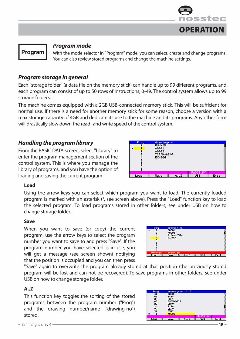
ProgramProgram modeWith the mode selector in ”Program” mode, you can select, create and change programs. Youcanalsoreviewstoredprogramsandchangethemachinesettings.
Program storage in generalEach "storage folder" (a data file on the memory stick) can handle up to 99 different programs, and each program can consist of up to 50 rows of instructions, 0-49. The control system allows up to 99 storage folders.The machine comes equipped with a 2GB USB-connected memory stick. This will be sufficient for normal use. If there is a need for another memory stick for some reason, choose a version with a max storage capacity of 4GB and dedicate its use to the machine and its programs. Any other form will drastically slow down the read- and write speed of the control system.
Handling the program libraryFrom the BASIC DATA screen, select "Library" to enter the program management section of the control system. This is where you manage the library of programs, and you have the option of loading and saving the current program.
LoadUsing the arrow keys you can select which program you want to load. The currently loaded program is marked with an asterisk (*, see screen above). Press the "Load" function key to load the selected program. To load programs stored in other folders, see under USB on how to change storage folder.
SaveWhen you want to save (or copy) the current program, use the arrow keys to select the program number you want to save to and press "Save". If the program number you have selected is in use, you will get a message (see screen shown) notifying that the position is occupied and you can then press "Save" again to overwrite the program already stored at that position (the previously stored program will be lost and can not be recovered). To save programs in other folders, see under USB on how to change storage folder.
A..ZThis function key toggles the sorting of the stored programs between the program number ("Prog") and the drawing number/name ("drawing-no") stored.

Operating instructiOns 8344
20 2013-04-19
operaTion
Program storage in general, continued
USBPressing this function key opens the storage folder management. When you use the "Load" and "Save" functions within the USB storage folder management, you load/save an entire library of up to 99 programs in one go. The currently loaded storage folder is marked with an asterisk (*).Note: Loading another storage folder does not affect the currently loaded program.Thecontrol systemallows forup to99differentstorage folders (PA001.MY–PA099.MY),eachwith up to 99 programs – allowing for a total of 9801 programs to be stored on the USB memory stick.
Load: Loads the currently selected storage folder and all of its up to 99 programs from the USB memory stick. If there are any programs in the loaded storage folder, the names of program 0 in each folder is displayed in the "Status" column. By setting/changing the name for program 0 in the storage folder, you can set/change the name displayed for each storage folder. If the current program hasn't been saved, you will be prompted to save the program as well as the entire storage folder.
Save: Saves or copies the currently loaded storage folder (up to 99 programs) to selected folder (PA001.MY–PA099.MY).Ifyouwanttosavechangestothecurrently loaded storage folder, press "Save" with the currently loaded storage folder selected (marked with an asterisk, *).If the current program hasn't been saved, you will be prompted to save the program with another press on "Save", or ignore the warning by pressing both "Ignore" buttons at the same time.
A...Z: As with programs, this function key toggles the sorting of the storage folders by order ("File name") or by name ("Status" column).

8344 English, rev 4 21
operaTion
Deleting whole or parts of a programIt is easy to delete all or part of a program. From the BASIC DATA menu, press the function key labelled ”Program”. This takes you to the program sequence. If you press the ”Clr prog” function key on program step 1, the entire program is deleted. ”Clr prog” deletes the line containing the marker and all lines after it. The fun-ction key labelled ”Delete” deletes only the line con-taining the marker.
Operating instructiOns 8344
22 2013-04-19
operaTion
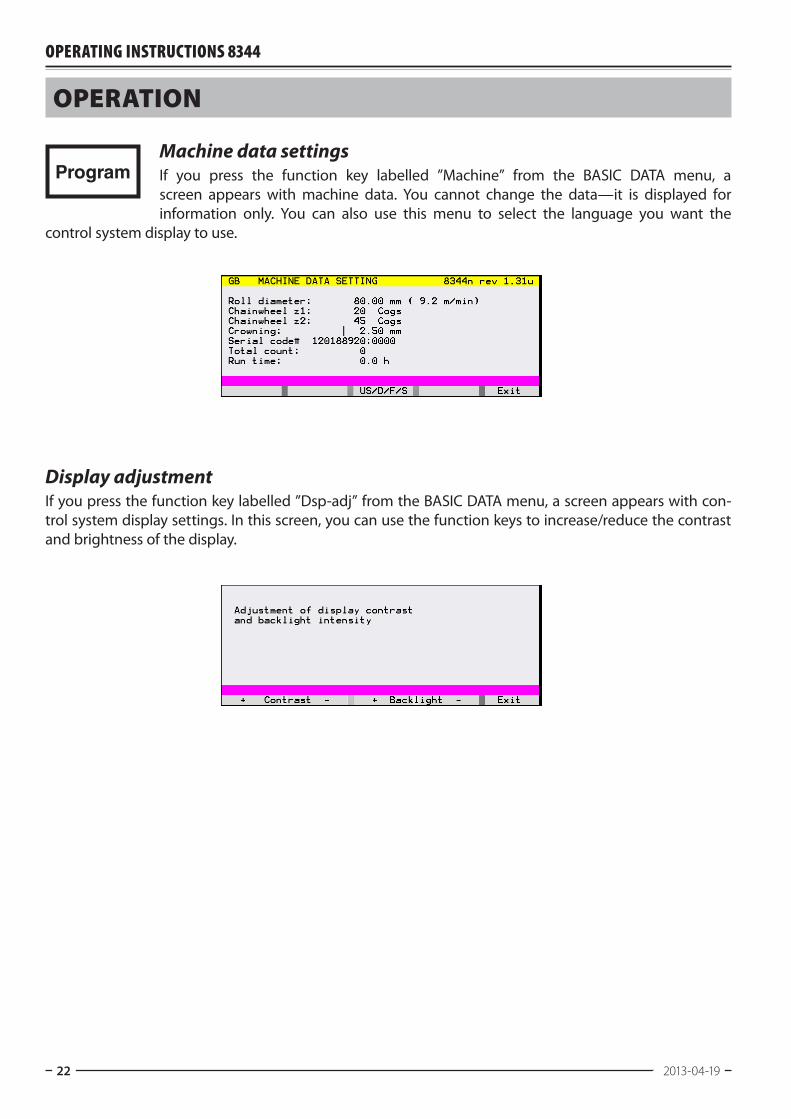
ProgramMachine data settingsIf you press the function key labelled ”Machine” from the BASIC DATA menu, a screen appears withmachine data. You cannot change the data—it is displayed forinformation only. You can also use this menu to select the language you want the
control system display to use.
Display adjustmentIf you press the function key labelled ”Dsp-adj” from the BASIC DATA menu, a screen appears with con-trol system display settings. In this screen, you can use the function keys to increase/reduce the contrast and brightness of the display.
8344 English, rev 4 23
operaTion
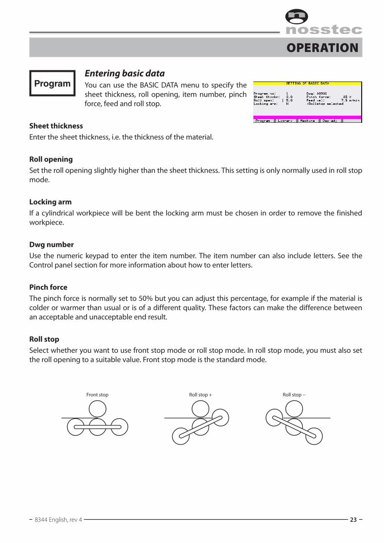
ProgramEntering basic dataYoucanuse theBASICDATAmenu to specify thesheet thickness, roll opening, item number, pinch force, feed and roll stop.
Sheet thicknessEnter the sheet thickness, i.e. the thickness of the material.
Roll openingSet the roll opening slightly higher than the sheet thickness. This setting is only normally used in roll stop mode.
Locking armIf a cylindrical workpiece will be bent the locking arm must be chosen in order to remove the finished workpiece.
Dwg numberUse the numeric keypad to enter the item number. The item number can also include letters. See the Control panel section for more information about how to enter letters.
Pinch forceThe pinch force is normally set to 50% but you can adjust this percentage, for example if the material is colder or warmer than usual or is of a different quality. These factors can make the difference between an acceptable and unacceptable end result.
Roll stopSelect whether you want to use front stop mode or roll stop mode. In roll stop mode, you must also set the roll opening to a suitable value. Front stop mode is the standard mode.
Front stop Roll stop + Roll stop −
Operating instructiOns 8344
24 2013-04-19
operaTion
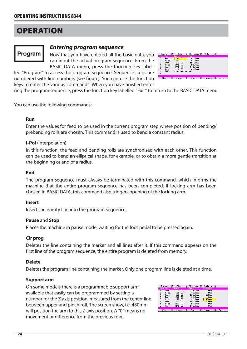
ProgramEntering program sequenceNow that you have entered all the basic data, you can input the actual program sequence. From the BASIC DATA menu, press the function key label-
led ”Program” to access the program sequence. Sequence steps are numberedwithlinenumbers(seefigure).Youcanusethefunctionkeys to enter the various commands. When you have finished ente-ring the program sequence, press the function key labelled ”Exit” to return to the BASIC DATA menu.
Youcanusethefollowingcommands:
RunEnter the values for feed to be used in the current program step where position of bending/prebending rolls are chosen. This command is used to bend a constant radius.
I-Pol (interpolation)In this function, the feed and bending rolls are synchronised with each other. This function can be used to bend an elliptical shape, for example, or to obtain a more gentle transition at the beginning or end of a radius.
EndThe program sequence must always be terminated with this command, which informs the machine that the entire program sequence has been completed. If locking arm has been chosen in BASIC DATA, this command also triggers opening of the locking arm.
InsertInserts an empty line into the program sequence.
Pause and StopPlaces the machine in pause mode, waiting for the foot pedal to be pressed again.
Clr progDeletes the line containing the marker and all lines after it. If this command appears on the first line of the program sequence, the entire program is deleted from memory.
DeleteDeletes the program line containing the marker. Only one program line is deleted at a time.
Support armOn some models there is a programmable support arm available that easily can be programmed by setting a number for the Z-axis position, measured from the center line between upper and pinch roll. The screen show, i.e. 480mm will position the arm to this Z-axis position. A ”0” means no movement or difference from the previous row.
8344 English, rev 4 25
operaTion
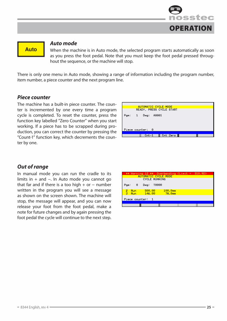
AutoAuto modeWhen the machine is in Auto mode, the selected program starts automatically as soon as you press the foot pedal. Note that you must keep the foot pedal pressed throug-hout the sequence, or the machine will stop.
There is only one menu in Auto mode, showing a range of information including the program number, item number, a piece counter and the next program line.
Piece counterThe machine has a built-in piece counter. The coun-ter is incremented by one every time a program cycle is completed. To reset the counter, press the function key labelled ”Zero Counter” when you start working. If a piece has to be scrapped during pro-duction, you can correct the counter by pressing the ”Count-1” function key, which decrements the coun-ter by one.
Out of rangeIn manual mode you can run the cradle to its limits in + and −. In Auto mode you cannot go that far and if there is a too high + or − number written in the program you will see a message as shown on the screen shown. The machine will stop, the message will appear, and you can now release your foot from the foot pedal, make a note for future changes and by again pressing the foot pedal the cycle will continue to the next step.
Operating instructiOns 8344
26 2013-04-19
operaTion
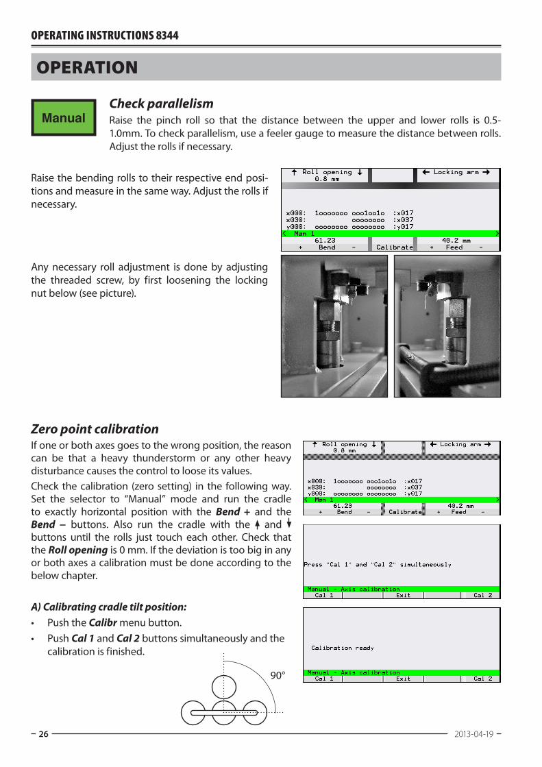
ManualCheck parallelismRaise the pinch roll so that the distance between the upper and lower rolls is 0.5-1.0mm. To check parallelism, use a feeler gauge to measure the distance between rolls. Adjust the rolls if necessary.
Raise the bending rolls to their respective end posi-tions and measure in the same way. Adjust the rolls if necessary.
Any necessary roll adjustment is done by adjusting the threaded screw, by first loosening the locking nut below (see picture).
Zero point calibrationIf one or both axes goes to the wrong position, the reason can be that a heavy thunderstorm or any other heavy disturbance causes the control to loose its values.Check the calibration (zero setting) in the following way. Set the selector to “Manual” mode and run the cradle to exactly horizontal position with the Bend + and the Bend − buttons. Also run the cradle with the and buttons until the rolls just touch each other. Check that the Roll opening is 0 mm. If the deviation is too big in any or both axes a calibration must be done according to the below chapter.
A) Calibrating cradle tilt position:• Push the Calibr menu button.• Push Cal 1 and Cal 2 buttons simultaneously and the
calibration is finished.
90°
8344 English, rev 4 27
operaTion
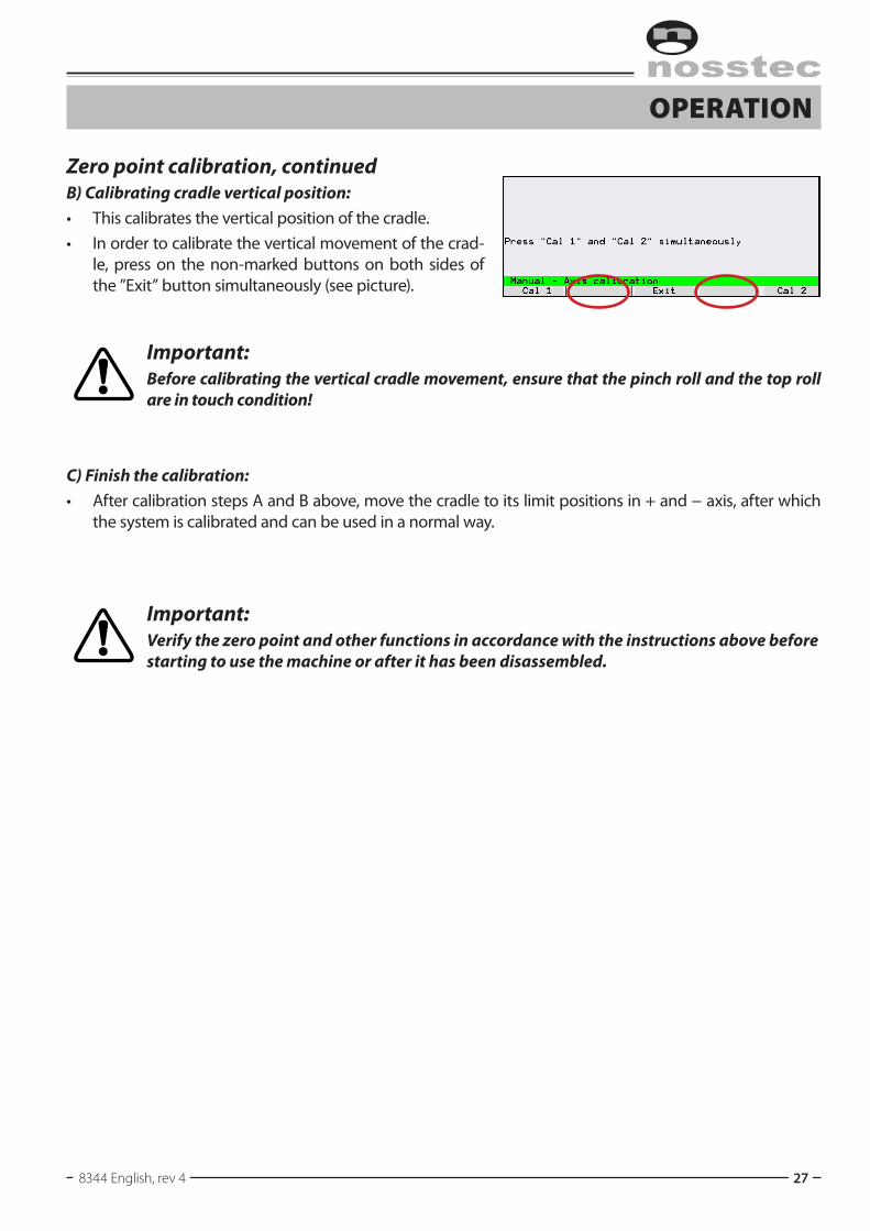
Zero point calibration, continuedB) Calibrating cradle vertical position:• This calibrates the vertical position of the cradle.• In order to calibrate the vertical movement of the crad-
le, press on the non-marked buttons on both sides of the ”Exit” button simultaneously (see picture).
Important:Before calibrating the vertical cradle movement, ensure that the pinch roll and the top roll are in touch condition!
C) Finish the calibration:• After calibration steps A and B above, move the cradle to its limit positions in + and − axis, after which
the system is calibrated and can be used in a normal way.
Important:Verify the zero point and other functions in accordance with the instructions above before starting to use the machine or after it has been disassembled.
Operating instructiOns 8344
28 2013-04-19
prograMMing
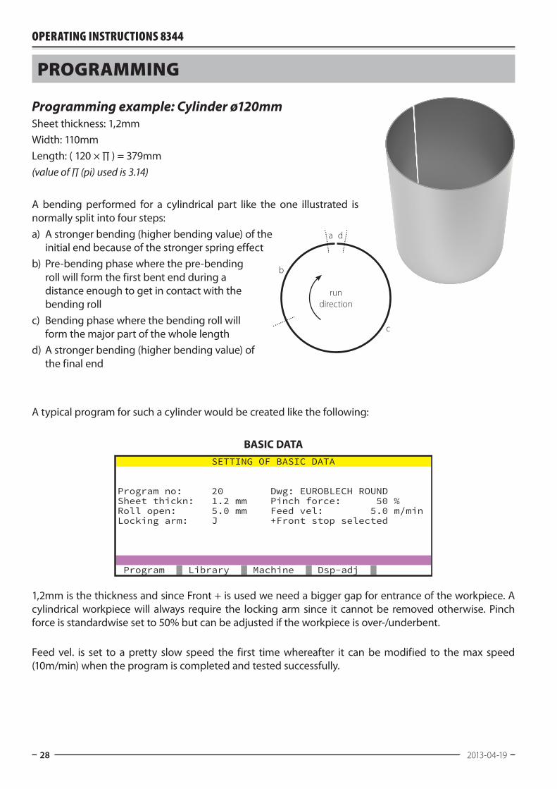
Programming example: Cylinder ø120mmSheet thickness: 1,2mmWidth: 110mmLength: ( 120 × ∏ ) = 379mm(value of ∏ (pi) used is 3.14)
A bending performed for a cylindrical part like the one illustrated is normally split into four steps:a) A stronger bending (higher bending value) of the
initial end because of the stronger spring effectb) Pre-bending phase where the pre-bending
roll will form the first bent end during a distance enough to get in contact with the bending roll
c) Bending phase where the bending roll will form the major part of the whole length
d) A stronger bending (higher bending value) of the final end
A typical program for such a cylinder would be created like the following:
BASIC DATA
1,2mm is the thickness and since Front + is used we need a bigger gap for entrance of the workpiece. A cylindrical workpiece will always require the locking arm since it cannot be removed otherwise. Pinch force is standardwise set to 50% but can be adjusted if the workpiece is over-/underbent. Feed vel. is set to a pretty slow speed the first time whereafter it can be modified to the max speed (10m/min) when the program is completed and tested successfully.
SETTING OF BASIC DATA
Program no: 20 Dwg: EUROBLECH ROUNDSheet thickn: 1.2 mm Pinch force: 50 %Roll open: 5.0 mm Feed vel: 5.0 m/minLocking arm: J +Front stop selected
Program Library Machine Dsp-adj
a d
b
run direction
c

8344 English, rev 4 29
prograMMing
Programming example, continuedPROGRAM
Row 1: Since Front + is used approximately 41mm in the current machine (8344, ø90mm rolls) must be run backwards. The workpiece is now in the middle of the mid rolls, e.g. the starting point of section a.
Row 2: RUN -129 (BEND) +3 FEED means that prebending roll will position at -129 and the workpiece will run for a distance of 3mm – segment a from principal sketch on previous page.
Row 3: Pre-bending phase – see segment b from principal sketch on previous page.
Row 4: Bending phase – see segment c from principal sketch on previous page.
Row 5: Final end is bent – see segment d from principal sketch on previous page.
Row 6: End of program and locking arm will open in order for the operator to remove the workpiece and a new cycle can be run.
Pause Stop Clr prog Delete Line Op Bend Feed 1 Run 0.00 -41.0mm 2 Run -129.00 3.0mm 3 Run -126.00 100.0mm 4 Run 279.00 271.0mm 5 Run 281.00 3.0mm 6 END ************* 7 8
Run I-pol End Insert Exit
Operating instructiOns 8344
30 2013-04-19
service and MainTenance
Daily check• All emergency stop functions• Lubrication according to grease chart
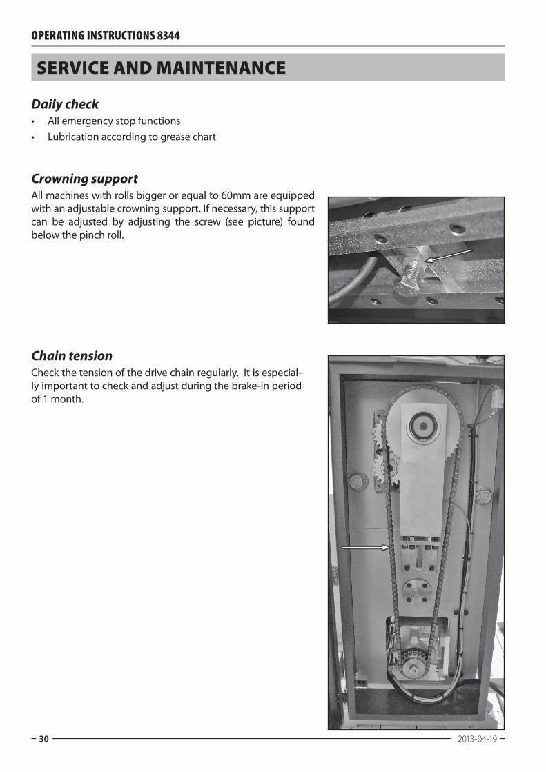
Crowning supportAll machines with rolls bigger or equal to 60mm are equipped with an adjustable crowning support. If necessary, this support can be adjusted by adjusting the screw (see picture) found below the pinch roll.
Chain tensionCheck the tension of the drive chain regularly. It is especial-ly important to check and adjust during the brake-in period of 1 month.
8344 English, rev 4 31
service and MainTenance
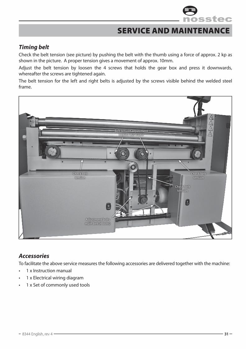
Timing beltCheck the belt tension (see picture) by pushing the belt with the thumb using a force of approx. 2 kp as shown in the picture. A proper tension gives a movement of approx. 10mm.Adjust the belt tension by loosen the 4 screws that holds the gear box and press it downwards, whereafter the screws are tightened again.The belt tension for the left and right belts is adjusted by the screws visible behind the welded steel frame.
AccessoriesTo facilitate the above service measures the following accessories are delivered together with the machine:• 1 x Instruction manual• 1 x Electrical wiring diagram• 1 x Set of commonly used tools
Check belt tension
Adjustment bolts main belt (4 bolts)
Belt tension adjustment behind this frame
Check belt tension
Check belt tension

Operating instructiOns 8344
32 2013-04-19
lubricaTion / grease charT
Lubrication pointsAs lubricant, use some sort of universal grease.Contact Nosstec if you are uncertain whether a specific grease is suited for this machine.
Every day:1 Top roll bearing and bushings on locking arm (1 nipple).
Every week:2 Eccentric straps for pinch force movement (2 nipples
located on front of the machine’s left and right side).
Every month:3 Prebending roll bearings.4 Bending roll bearings.5 Cradle bearings.6 Pinch roll bearings.7 Left top roll bearing.8 Only for roll diameter 60mm and up: Bottom rolls crowning
support (4 nipples/support, number of supports depending on machine size). See pictures opposite page.
Top roll on locking arm side should be greased every day.
1
Prebending rolls, grease every month.
Cradle bearings, left and right. Grease every month.
Left and right pinch roll bearing. Grease every month.
Left top roll bearing. Grease every month.
Bending rolls, grease every month.
2
Excentric straps for pinch force, grease nipples located on the front of the machine.
3 3 4 4
55 6
76
6
1
6 1
8344 English, rev 4 33
lubricaTion / grease charT
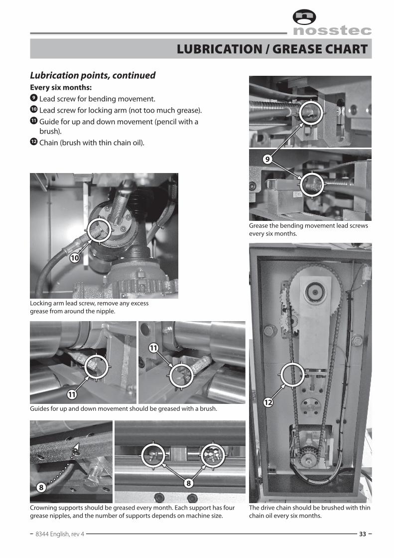
Lubrication points, continuedEvery six months:
9 Lead screw for bending movement.10 Lead screw for locking arm (not too much grease).11 Guide for up and down movement (pencil with a
brush).12 Chain (brush with thin chain oil).
11
1211
10
Crowning supports should be greased every month. Each support has four grease nipples, and the number of supports depends on machine size.
Guides for up and down movement should be greased with a brush.
The drive chain should be brushed with thin chain oil every six months.
Grease the bending movement lead screws every six months.
9
8 8
Locking arm lead screw, remove any excess grease from around the nipple.
Operating instructiOns 8344
34 2013-04-19
fuses and MoTor proTecTion
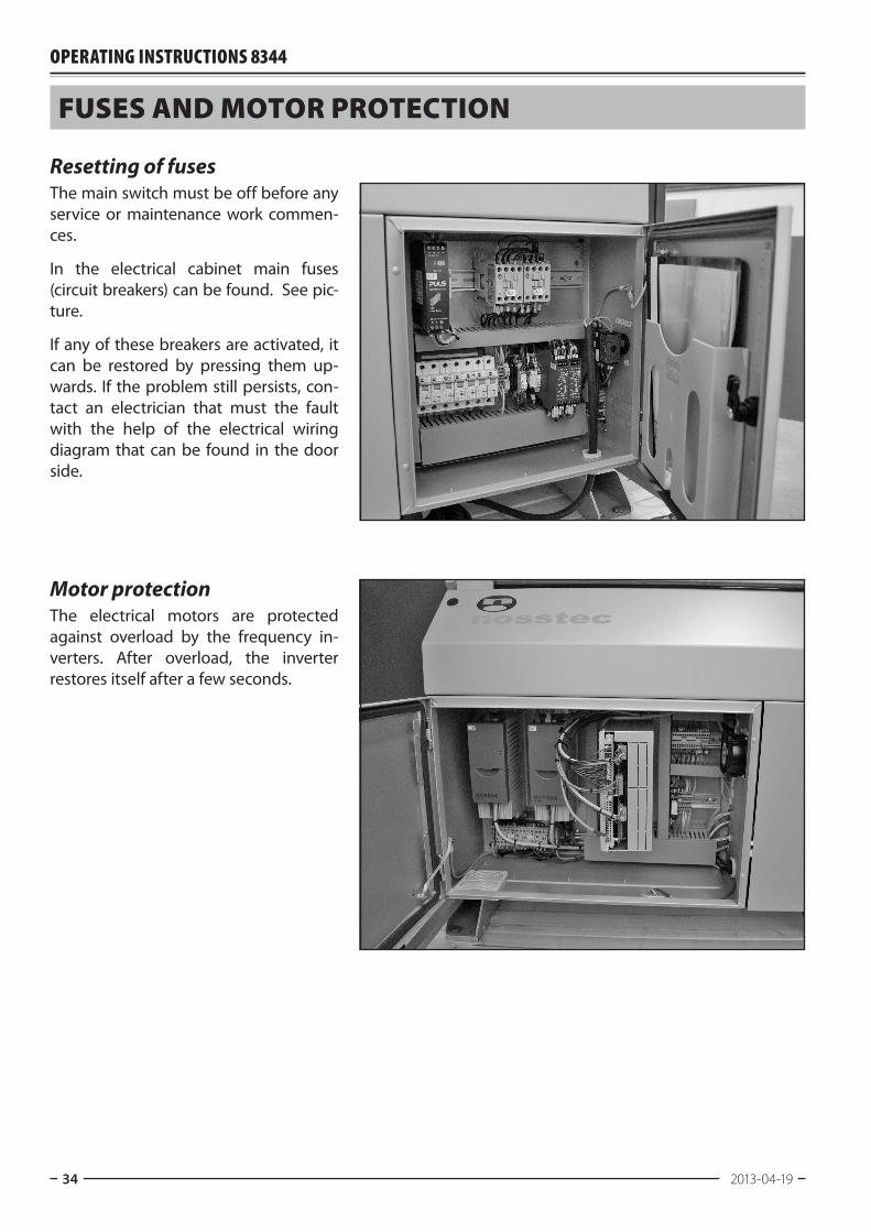
Resetting of fusesThe main switch must be off before any service or maintenance work commen-ces.
In the electrical cabinet main fuses (circuit breakers) can be found. See pic-ture.
If any of these breakers are activated, it can be restored by pressing them up-wards. If the problem still persists, con-tact an electrician that must the fault with the help of the electrical wiring diagram that can be found in the door side.
Motor protectionThe electrical motors are protected against overload by the frequency in-verters. After overload, the inverter restores itself after a few seconds.
8344 English, rev 4 35
Technical daTaSerial No . . . . . . . . . . . . . . . . . . . . . . . . . . . . . . . . . . . . . . . . . . . . . . . . . . . . . . . . . . . . . . . . . . . . . . . . . . . . . . .
Type . . . . . . . . . . . . . . . . . . . . . . . . . . . . . . . . . . . . . . . . . . . . . . . . . . . . . . . . . . . . . . . . . . . . . . . . . . . . . . . . . . . . .
Max. sheet thickness (at 400 N/mm2) . . . . . . . . . . . . . . . . . . . . . . . . . . . . . . . . . . . . . . . . . . mmOperating length . . . . . . . . . . . . . . . . . . . . . . . . . . . . . . . . . . . . . . . . . . . . . . . . . . . . . . . . . . . . . . . . . . . . mmTotal net weight . . . . . . . . . . . . . . . . . . . . . . . . . . . . . . . . . . . . . . . . . . . . . . . . . . . . . . . . . . . . . . . . . . . . . kgWeight of rolls . . . . . . . . . . . . . . . . . . . . . . . . . . . . . . . . . . . . . . . . . . . . . . . . . . . . . . . . . . . . . . . . . . . . . . . . kg/mTotal dimensions: length × width × height . . . . . . . . . . . . . . . . . . . . . . . . . . . . . . . . . . mmWorking height . . . . . . . . . . . . . . . . . . . . . . . . . . . . . . . . . . . . . . . . . . . . . . . . . . . . . . . . . . . . . . . . . . . . . . mmFuse . . . . . . . . . . . . . . . . . . . . . . . . . . . . . . . . . . . . . . . . . . . . . . . . . . . . . . . . . . . . . . . . . . . . . . . . . . . . . . . . . . . . . AVoltage . . . . . . . . . . . . . . . . . . . . . . . . . . . . . . . . . . . . . . . . . . . . . . . . . . . . . . . . . . . . . . . . . . . . . . . . . . . . . . . . . VFeeding motor: Brand . . . . . . . . . . . . . . . . . . . . . . . . . . . . . . . . . . . . . . . . . . . . . . . . . . . . . . . . . . . . . . . . . . . . . . . . . . . . .
Type . . . . . . . . . . . . . . . . . . . . . . . . . . . . . . . . . . . . . . . . . . . . . . . . . . . . . . . . . . . . . . . . . . . . . . . . . . . . . .
. . . . . . . . . . . . . . . . . . . . . . . . . . . . . . . . . . . . . . . . . . . . . . . . . . . . . . . . . . . . . . . . . . . . . . . . . . . . . . . . . . . . . V . . . . . . . . . . . . . . . . . . . . . . . . . . . . . . . . . . . . . . . . . . . . . . . . . . . . . . . . . . . . . . . . . . . . . . . . . . . . . . . . . . . . . kW Bending rolls motor: Brand . . . . . . . . . . . . . . . . . . . . . . . . . . . . . . . . . . . . . . . . . . . . . . . . . . . . . . . . . . . . . . . . . . . . . . . . . . . . .
Type . . . . . . . . . . . . . . . . . . . . . . . . . . . . . . . . . . . . . . . . . . . . . . . . . . . . . . . . . . . . . . . . . . . . . . . . . . . . . .
. . . . . . . . . . . . . . . . . . . . . . . . . . . . . . . . . . . . . . . . . . . . . . . . . . . . . . . . . . . . . . . . . . . . . . . . . . . . . . . . . . . . . V . . . . . . . . . . . . . . . . . . . . . . . . . . . . . . . . . . . . . . . . . . . . . . . . . . . . . . . . . . . . . . . . . . . . . . . . . . . . . . . . . . . . . kW Pinching roll motor: Brand . . . . . . . . . . . . . . . . . . . . . . . . . . . . . . . . . . . . . . . . . . . . . . . . . . . . . . . . . . . . . . . . . . . . . . . . . . . . .
Type . . . . . . . . . . . . . . . . . . . . . . . . . . . . . . . . . . . . . . . . . . . . . . . . . . . . . . . . . . . . . . . . . . . . . . . . . . . . . .
. . . . . . . . . . . . . . . . . . . . . . . . . . . . . . . . . . . . . . . . . . . . . . . . . . . . . . . . . . . . . . . . . . . . . . . . . . . . . . . . . . . . . V . . . . . . . . . . . . . . . . . . . . . . . . . . . . . . . . . . . . . . . . . . . . . . . . . . . . . . . . . . . . . . . . . . . . . . . . . . . . . . . . . . . . . Kw Top roll bearing arm movement motor: Brand . . . . . . . . . . . . . . . . . . . . . . . . . . . . . . . . . . . . . . . . . . . . . . . . . . . . . . . . . . . . . . . . . . . . . . . . . . . . .
Type . . . . . . . . . . . . . . . . . . . . . . . . . . . . . . . . . . . . . . . . . . . . . . . . . . . . . . . . . . . . . . . . . . . . . . . . . . . . . .
. . . . . . . . . . . . . . . . . . . . . . . . . . . . . . . . . . . . . . . . . . . . . . . . . . . . . . . . . . . . . . . . . . . . . . . . . . . . . . . . . . . . . V . . . . . . . . . . . . . . . . . . . . . . . . . . . . . . . . . . . . . . . . . . . . . . . . . . . . . . . . . . . . . . . . . . . . . . . . . . . . . . . . . . . . . Kw Diameter of rolls . . . . . . . . . . . . . . . . . . . . . . . . . . . . . . . . . . . . . . . . . . . . . . . . . . . . . . . . . . . . . . . . . . . . . mm
Deviation from the normal execution:
Operating instructiOns 8344
36 2013-04-19
Machine plaTes and sTickers
Nosstec ABJärnvägsgatan 19465 30 NossebroSWEDEN
Productionyear:
Type:
Capacity:
Weight:
Serial No:
Kg.
mm
Current:
Voltage:
Phase:
Frequency:
Aluminium plate, blue anodized.
MAIN SWITCH MUST BE DISCONNECTED FOR ALL TYPES OF SERVICE AND
MAINTENANCE
ONLY TRAINEDSTAFF MAY HANDLE
THIS MACHINE
White and yellow background, black text
White and yellow background, black text
Yellowbackground,black text
Yellowbackground,black text
Yellowbackground,black text
Yellowbackground,black text

8344 English, rev 4 37
declaraTion of conforMiTy
Declaration of conformityas per the EC Machinery Directive 98/37 EG, Annex II A.
Manufacturer: Nossebro Mekaniska Verkstad AB SE 465 30 NOSSEBRO +46 512 298 80
Distributor: Nosstec AB SE 465 30 NOSSEBRO +46 512 298 85
herewith declare that:
Machine: . . . . . . . . . . . . . . . . . . . . . . . . . . . . . . . . . . . . . . . . . . . . . . . . . . . . . . . . . . . . . . Type
. . . . . . . . . . . . . . . . . . . . . . . . . . . . . . . . . . . . . . . . . . . . . . . . . . . . . . . . . . . . . . Serial No
is manufactured in conformity with: – The Council Directive of 2006/42/EG – EMC Directive 2004/108/EG – Low voltage directive 2009/96/EG
. . . . . . . . . . . . . . . . . . . . . . . . . . . . . . . . . . . . . . . . . . . . . . . . . . . . . . . . . . . . . . . . . . . . . . . . .Place and date Signature, Managing Director
Operating instructiOns 8344
38 2013-04-19
appendiX ø40MM version
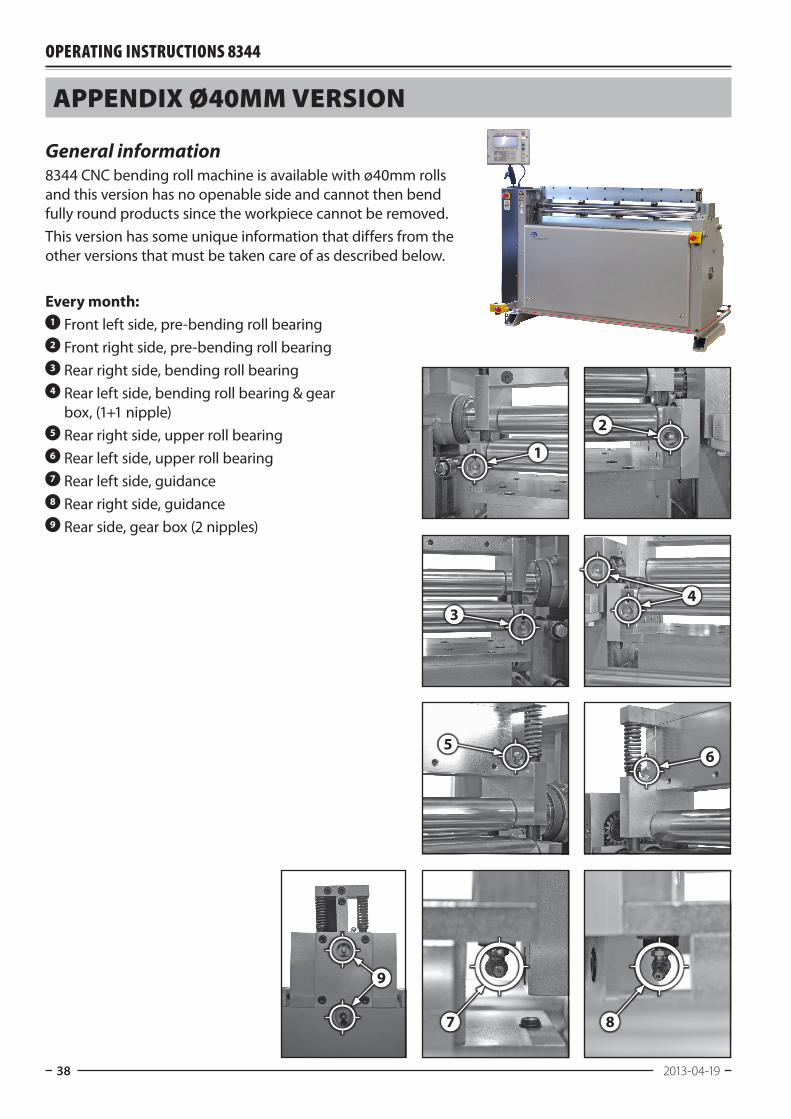
General information8344 CNC bending roll machine is available with ø40mm rolls and this version has no openable side and cannot then bend fully round products since the workpiece cannot be removed.This version has some unique information that differs from the other versions that must be taken care of as described below.
Every month:1 Front left side, pre-bending roll bearing2 Front right side, pre-bending roll bearing3 Rear right side, bending roll bearing4 Rear left side, bending roll bearing & gear
box, (1+1 nipple)5 Rear right side, upper roll bearing6 Rear left side, upper roll bearing7 Rear left side, guidance8 Rear right side, guidance9 Rear side, gear box (2 nipples)
1
4
6
9
7 8
3
2
5


www.nosstec.se
Nosstec AB • Kristineholmsvägen 12, 441 39 Alingsås, SWEDENTel: +46 (0)512 298 85 • Fax: +46 (0)512 298 89 • E-mail: [email protected]
For copyright reasons all reproduction and copying of the texts, tables and illustrations within this manual is prohibited without written permission from Nosstec AB.