benchstudy of chlordane and dieldrin … benchstudy of chlordane and dieldrin adsorption...
TRANSCRIPT
WRRC-99-06
BENCH STUDY OF CHLORDANE AND DIELDRIN ADSORPTION
Roger Babcock, JrElisa Amantiad
Christine.IshikawaMitch Uehara
November, 1999
Prepared for
Brown and Caldwell, Inc.119 Merchant Street, Suite 200Honolulu, Hawaii 96813-4499
Project Reportfor
"Granular Activated Carbon Adsorption of Chlordane and Dieldrin"
Project Period: 10 June 1999 - 15 October 1999
Principal Investigator: Roger W. Babcock, Jr.
WATER RESOURCES RESEARCH CENTERUNIVERSITY OF HAWAI'! AT MANOA
Honolulu, Hawaii 96822
Any opinions, findings, and conclusions or recommendations expressed in this publication are those of the authorsand do not necessarily reflect the view of the Water Resources Research Center.
Bench-Study of ClIordanc and Dieldrin Adsorptioa
CONTENTS
1.0 INTRODUCflON 2
1.1 History of Chlordane and Dieldrin in Hawaii 21.2 Chlordane and Dieldrin in Board of Water Supply Wells 21.3 Removal of Chlordane and Dieldrin with Granular Activated
Carbon Using Small Scale Columns 3
2.0 METHODS 4
2.1 Small-Scale Column Calculations 42.2 Analytical Methods 42.3 Carbon Preparation 52.4 Column Setup " 52.5 Pump Set up and Operation 62.6 Extraction and GC Analysis 62.7 Experimental Runs " 6
3.0 RESULTS 9
4.0 PRELIMINARY CONCLUSIONS AND FUTIJRE WORK 13
5.0 REFERENCES 14
APPENDICES
I Standard Curves : ". . . . .. . . .. ... . .. ... .. ... 15IT Mini-Column Equipment Set-up 16ill Chlordane Chromatogram...... . . . .. . .. . .... .. . . . .. . . . . . . .. .. . .. . . . ... . .. ... .. .. .. . . 17IV Mini-Column Scaling Calculations 18
Pap 1
8cDch-Sbldyof a1Iordane and DieldrinAdsorption
1.0 INTRODUCTION
1.1 History ofChlordane and Dieldrin in Hawaii
Chlordane and dieldrin were introduced to Hawaii as pesticides used mainly for termitecontrol, crop cultivation, and landscaping. Chlordane and dieldrin are chlorinated hydrocarbons.They do not break down easily, and as a result their toxicity remains for a long period of time.When released to soil, they are very persistent. They can reach the air by volatilization, oradsorption onto dust particles. Soil run-off transports chlordane and dieldrin into water systems.When released to water, chlordane and dieldrin do not undergo hydrolysis or biodegradation.Both have the tendency to adsorb to sediments present in water (Spectrum Laboratories, Inc.,1998).
The EPA banned all uses of chlordane in April 1988 due to increasing environmental andhealth concerns (Brown & Caldwell, 1998). In 1992, the EPA set the maximum contaminantlevel at 2 ppb with a MCL goal of zero ppb. Chlordane is a suspected carcinogen. It may enterthe human body by ingestion, inhalation, skin absorption, and possibly other routes. Chlordaneaffects the nervous system, digestive system, and the liver. Symptoms of exposure of lowerconcentrations include nausea, headaches, abdominal pain, and vomiting. At higherconcentrations, symptoms include convulsions, unconsciousness, or even death. Long termexposure may cause cancer, reproductive, liver, and kidney damage, and acne-like rash (Brown &Caldwell, 1998). Technical chlordane consists of several isomers and related compoundsincluding primarily cis<hlordane, trans<hlordane, cis-nonacblor, tran.s-nonachlor, heptachlor,and octaehlordane (Dearth and Hites, 1991).
In October 1974, the EPA banned dieldrin from all agricultural use. In 1989, it wasbanned for termite control (Brown & Caldwell, 1998). Currently, there is no federal MCL fordrinking water. However, EPA has proposed a long-term health advisory level of 0.5 ppb. Thesolubility of dieldrin is about 190 ppb (Pirbazari and Weber, 1984). Like chlordane, dieldrin mayenter the human body by ingestion, inhalation, skin contact, and other possible routes.Laboratory test results show that dieldrin may be carcinogenic and teratogenic. Acute effectsinclude headaches, dizziness, irritability, loss of appetite, nausea. muscle twitching, convulsions,loss of consciousness, and even death at higher doses. Long term exposure may lead toheadaches, dizziness, vomiting, irritability and muscle spasms (Brown & Caldwell, 1998).
· 1.2 Ghlordllneand Dieldrin inBoard ofWater Supply Welb
The Honolulu Board of Water Supply (BWS) has detected chlordane and dieldrin inseveral wells in the Honolulu area. Dieldrin was detected at Wilder Ave., Kaimuki, Kalihi, andJonathan Springs. Both chlordane and dieldrin were detected inJonathan Springs. TheJonathanSprings well is not currently in operation. 1be Kaimuki and Kalihi wells operate intermittentlyand contain very low concentrations of dieldrin, making them poor candidates for obtainingsamples for use in adsorption experiments. 1be Wilder Avenue wells (except the one well inwhich dieldrin was detected) are in service pumping a mean of 6.99 mgd of water to the vicinity.
Bench-Study of Chlordane and Dieldrin Adsorption
One of the Wilder Ave. wells contains approximately 0.0 I ppb of dieldrin. Uncontaminatedwater from Wilder Avenue was utilized in this research.
1.3 Removal ofChlordane and Dieldrin with Granular Activated Carbon .Using SmallScale Columns
Because granular activated carbon (GAC) has a large surface area, the force of attractionthe GAC has on the pesticides is greater than the force which keeps the pesticides suspended inthe water. These pesticides have high molecular weights, therefore they are less soluble in waterand readily adsorbed onto the carbon.
The objective of this research is to facilitate the design of full-scale GAC columns.Because full-scale and even pilot-scale GAC adsorption experiments ate very time-consumingand expensive, this research explores the efficiency of GAC in bench-scale columns. Rapidsmall-scale column tests (RSSCfs) are commonly used to aid in the design of full-scale GACtreatment units . Procedures for design of such tests are well documented in the technicalliterature (Crittenden et al., 1987 and 1991). These bench-scale tests are more advantageous thanpilot-scale studies because the operation time is decreased, extensive isotherm or kinetic studiesare not required, and the volume of water required is minimal (Ewald, 1998). However, it isrecommended that pilot studies follow the RSSCfs prior to full-scale design.
The use of GAC for removal of chlordane anddieldrin in Hawaii's BWS wells is nonexistent. Currently, there are five BWS pumping stations that have successfully used GAC forthe removal of other pesticides (primarily EDB, TCP and DBCP) since 1986. These pumpingstations include Mililani I and II, Kunia II, and Waipahu I and II. Because of the similar natureof DBCP to chlordane and dieldrin, it is anticipated that GAC will also be successful forremoval of these chemicals (Brown & Caldwell, 1998).
Page 3
Bench-Studyof 0tI0rdane and DieldrinAdsorpOoD
2.0 METHODS
2.1 SnuJU-Scale Column Calculations
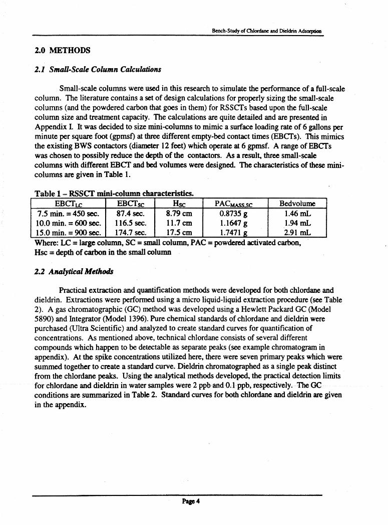
Small-scale columns were used in this research to simulate the performance of a full-scalecolumn. The literature contains a set of design calculations for properly sizing the small-scalecolumns (and the powdered carbon that goes in them) for RSSCfs based upon the full-scalecolumn size and treatment capacity. The calculations are quite detailed and are presented inAppendix I. It was decided to size mini-columns to mimic a surface loading rate of 6 gallons perminute per square foot (gpmsf) at three different empty-bed contact times (EBCfs). This mimicsthe existing BWS contactors (diameter 12 feet) which operate at 6 gpmsf. A range of EBCfswas chosen to possibly reduce the depth of the contaetors. As a result. three small-scalecolumnswith different EBCf and bed volumes were designed. The characteristics of these minicolumns are given in Table 1.
Table 1 - RSScr mini-column characteristics.EBCfLe EBCfsc lise PACMASS sc Bedvolume
7.5 min. =450 sec. 87.4 sec. 8.79 cm 0.8735 g 1.46 mL10.0 min. =600 sec. 116.5 sec. 11.7 em 1.1647 g 1.94mL15.0 min. =900 sec. 174.7 sec. 17.5 cm 1.7471 g 2.91 mLWhere: LC =large column, SC =small column, PAC =powdered activated carbon,Hsc = depth of carbon in the small column
2.2 Analytieal Methods
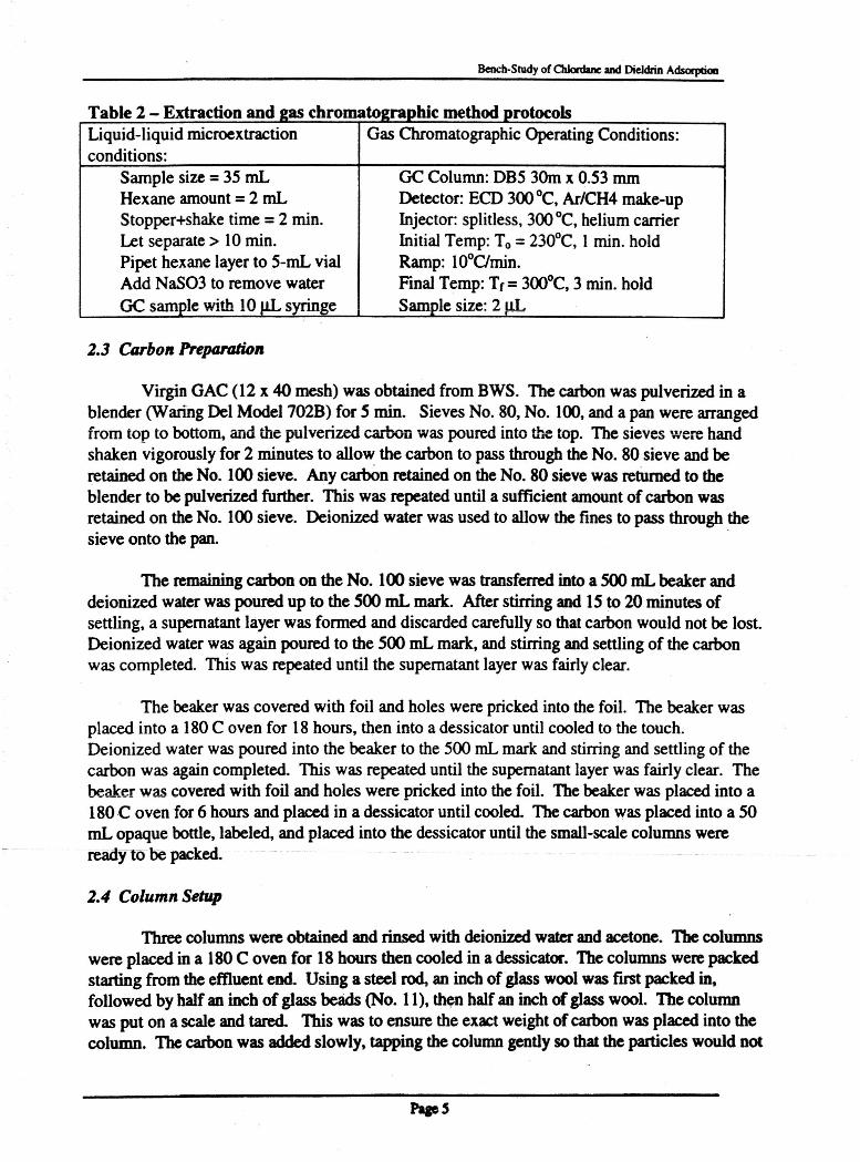
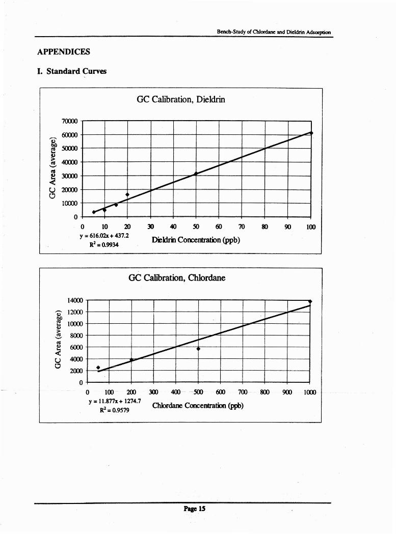
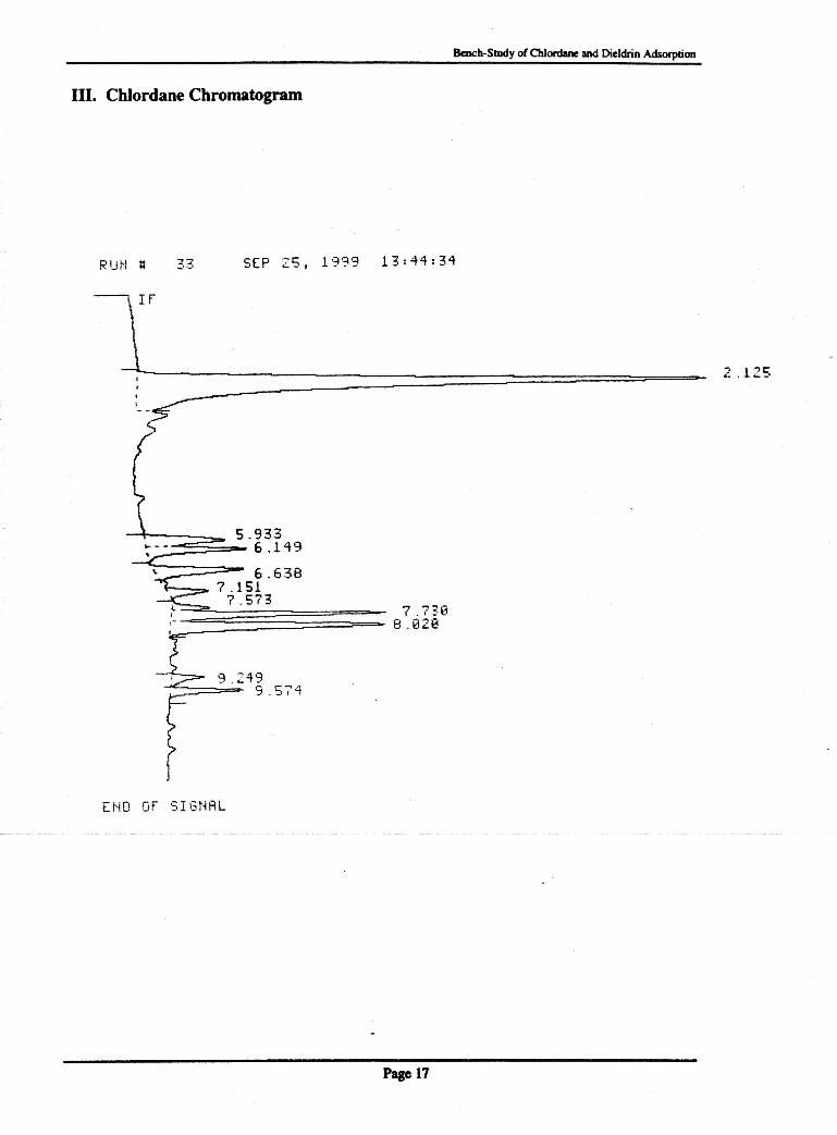
Practical extraction and quantification methods were developed for both chlordane anddieldrin. Extractions were performed using a micro liquid-liquid extraction procedure (see Table2) . A gas chromatographic (GC) method was developed using a Hewlett Packard GC (Model5890) and Integrator (Model 1396). Pure chemical standards of chlordane and dieldrin werepurchased (Ultra Scientific) and analyzed to create standard curves for quantification ofconcentrations. As mentioned above, technical chlordane consists of several differentcompounds which happen to be detectable as separate peaks (see example chromatogram inappendix). At the spike concentrations utilized here, there were seven primary peaks which weresummed together to create a standard curve. Dieldrin chromatographed as a single peak distinctfrom the chlordane peaks. Using the analytical methods developed, the practical detection limitsfor chlordane and dieldrin in water sarnpleswere2 ppband O.lppb,respectively.The GCconditions are summarized in Table 2. Standard curves for both chlordane and dieldrin are givenin the appendix.
Page"
Bench-Study of 0tI0rdane and Dieldrin AdsorptioII
loelsthadhitohdT ble 2 Extra tia - c on an 285 C roma )2rapl C me pro 0
Liquid-liquid microextraction Gas Chromatographic Operating Conditions:conditions:
Sample size = 35 mL GC Column: DB5 30m x 0.53 mmHexane amount= 2 mL Detector: ECD 300°C, Ar/CH4 make-upStopper+shake time = 2 min. Injector: splitless, 300°C, heliumcarrierLet separate> 10 min. Initial Temp: To = 230°C, I min. holdPipet hexane layer to 5-mL vial Ramp: WOC/min.Add NaS03 to remove water Final Temp: Tf= 300°C, 3 min. holdGC sample with 10 J,1L syringe Sample size: 2 J,1L
2.3 Carbon PreptU'tltion
Virgin GAC (12 x 40 mesh) was obtained from BWS. The carbonwas pulverized in ablender (WaringDel Mode1702B) for 5 min. Sieves No. 80, No. 100, and a pan were arrangedfrom top to bottom,and the pulverized carbon was poured into the top. The sieves were handshaken vigorously for 2 minutes to allow the carbon to pass throughthe No. 80 sieve and beretained on the No. 100 sieve. Any carbon retained on the No. 80 sieve was returned to theblender to be pulverizedfurther. This was repeated until a sufficientamountof carbon wasretained on the No. 100 sieve. Deionized water was used to allow the fines to pass through thesieve onto the pan. .
The remaining carbon on the No. 100 sieve was transferred into a 500 mL beaker anddeionized waterwas poured up to the 500 mL mark. After stirringand 15 to 20 minutes ofsettling, a supernatant layer was formed and discardedcarefully so that carbon would not be lost.Deionized water wa;s again poured to the 500 mLmark, and stirringand settlingof the carbonwas completed. This was repeated until the supernatant layerwas fairly clear.
The beakerwas covered with foil and holes were pricked into the foil. The beaker wasplaced into a 180C oven for 18 hours, then into a dessicatoruntil cooled to the touch.Deionized waterwas poured into the beaker to the 500 mLmark and stirring and settling of thecarbon was again completed. This was repeated until the supernatant layerwas fairly clear. Thebeaker was covered with foil and holes were pricked into the foil. The beaker was placed into a180C oven for 6 hours and placed in a dessicatoruntil cooled. The carbon was placed into a 50mL opaque bottle, labeled, and placed into the dessicatoruntil the small-scale columns wereready to be packed.
2.4 Column Setup
Three columnswere obtained and rinsed with deionized water and acetone. Thecolumnswere placed in a 180C oven for 18 hours then cooled in a dessicator. The columns werepackedstarting from the effluent end. Using a steel rod, an inch ofglass woolwas first packed in,followed by half an inch of glass beads (No. 11), then half an inch of glass wool. The columnwas put on a scale and tared. This was to ensure the exactweightof carbon was placed into thecolumn. The carbon was added slowly, tapping thecolumngentlyso that the particles would not
Bench·Study of 0lI0rdane and DieldrinAdsoqlIion
adhere to the sides, until the exact desired weight of carbon was poured into the column. Thedepth was measured. More carbon was added until the calculated depth was desired. 1becolumn was weighedand recorded. A final layer of glass wool (one inch) was packed into thecolumn.
2.5 Pump Set up and Operation
The columns were each connected to a pressure gage and a high pressure HPLC pump(Dionex or Accuflow). Flows of approximately 1 mUmin were pumpedcontinuously by thepumps (see photos in the Appendix). This resulted in pressures in the range of 1500- 2500 psi.To ensure adequate flow rate, all air bubbles were removed from the influent and effluent lines.Initially, deionized waterwas pumped through the columns to wet thecarbon and to check if thesetup was correct. Deionizedwater was pumped continuouslyuntil watersamples were obtained.
Water samples were collected from Wilder Avenue BWS wells in 4-L amber bottles thenstored at 4°C until use. Before running samples through the columns, the water samples werespiked with 2 ppb of dieldrin or 20 ppb of chlordane.
2.6 Extraction andGC AlUllysis
Extractions of influent and effluent samples were completeddaily. First, the volume ofthe effluent was measuredand recorded. Next, 35-mLof the effluent was placed in a SO mLtube containing 7 grams of sodium chloride. With a micro-pipette, 2-mLof hexane was placedinto the tube. The tube was capped and shook for 2 minutes. After the2 minutes, two distinctlayers of hexane and waterwas formed. The top layerof hexane wasremoved with a pipette andplaced into a 15-mLcentrifuge tube. The centrifuge tube was placedon a Maxi Mixer I (Type.167(0) for 15 seconds. A 1Q-flL syringe was used to obtain 2 J.1L of extract from the centrifugetube. This was injected into the GC and the peak area was recorded to calculate pesticideconcentration.
2.7 Experimental Runs
Ideally, RSSCTsshould be run with actual contaminated water. This is important sinceboth the water matrix components (particularlydissolvednatural organicmatter, NOM) andtarget compound concentrations greatlyaffect the adsorption process. NOM is known toeffectively compete with syntheticpesticidesfor -adsorption sitesin general and this has beenshown in Hawaii as well for EDB, DBCP, and TCP (Ewald, 1998). Matrix effects cannot beignored or duplicatedin the laboratory. Similarly, the concentration of the target compoundaffects the run time of a GAC column and it is difficult to accurately extrapolate field-scaleperformance from bench-scale tests with spiked water. However, the constraints of thisprojectwere such that there was no available supply of actual water significantly contaminatedwithchlordane or dieldrin.
The next best case was to use actual water (from an adjacent operating uncontaminatedwell) spiked with knownquantities of purchased pesticidechemicals. In this way, at least the
Bench-Study of 0lI0nIaDeand Dieldrin A.dsorptioa
matrix effects would be considered. The next step was to decide what concentrations to utilizefor the spikes. This was decided based upon the practical detection limits for dieldrin (0.1 ppb)and chlordane (2 ppb), the existing MCIlhealth advisories (0.5 ppb and 2 ppb, respectively), andGAC adsorptionprocess characteristics. The practical detection limits are very similar to theMCI.Jhealth advisories which might imply that spikes of these magnitudes would be useful.However, target compound concentrations at or near the analytical detection limit pose a problemfor adsorption studies.
In general for GC methods, the highest uncertainty for quantification of pesticideconcentration occurs when workingat or near the detection limit. It would not be practical toutilize a spike concentrationequal to the practical detection limit, because there would always bedoubt regardingthe concentrationor even presence of the pesticides due to very tiny randomanalytical errors and tiny potentialerrors in the spiking procedure. This point can be illustratedas follows. If one were to look at the long-term monitoring data for the pesticides in BWS'sCentral Oahu wells, they would find that there is a certain degreeof variabilityboth in the shortterm and in the long term. The long-term variations are usually called trends (increasing ordecreasing). The short-term variations (i.e. between adjacent wells or between sampling datesfor a single well) are more difficult to interpret, but are generallyassumed to be related torandom errors due to sampling, handling, extraction, and analysis (rather than due to actualdifferences in the concentrationsin the water). Looking at the short-term variations, one wouldfmd that their magnitudewas similar to or even greater than the detection limit. -This means thatif a water sourcecontains a pesticideat a concentration near the detection limit, it will sometimesbe detected and sometimes will not be detected.
In addition, if a spike concentration equal to the practical detection limit were utilized, itwould not be possible to generatea breakthroughcurve. In adsorptionstudies, one looks for abreakthroughcurve to characterizethe adsorption process. A time series plot of the effluentpesticide concentration in an adsorption test generally consistsof a period of non-detectableconcentrationsfollowed by a rising saturation-typecurve which eventually increases to the pointwhere the effluent concentration equals the influent concentration (breakthrough curve). In orderto generate such a curve, the pesticidemust be detectable at a concentration of 1/5 to l/tO theinfluent concentration (so that the initiation of breakthrough can be observed in spite of any tinyrandom analytical errors). If the influentpesticide concentration is equal to the detection limit,then the first point at which it wouldbe detected in the effluent would be after complete carbonsaturation. The time for complete carbon saturation may be 20% (or more) longer than the timeto initial breakthrough. - ~ ---.-- ._.
Based upon these considerations, it was decided to utilize spike concentrations ofapproximately 10 times the practicaldetection limits (i.e. 2 ppb and 20 ppb for dieldrin andchlordane, respectively). A set of six experimental runs (RSSCfs) were selected (see Table 3).
"7
Bench-Studyof 0lI0rdane and Dieldrin Adsorption
te°tihtalT bl 3 Ea e - ~xpenmen rune ane ns esRun Compoundts) EBCf(min) Water type
1 Dieldrin 7.5 Spiked well water2 Dieldrin 10 Spiked well water3 Chlordane 7.5 Spiked well water4 Chlordane + Dieldrin 7.5 Spiked well water5 Chlordane + Dieldrin 7.5 Spiked well water6 Chlordane + Dieldrin 7.5 Spiked distilled water
The first two RSSCfs were designed to compare the effects of EBCf on dieldrinadsorption capacity. The fourth and fifth RSSCfs are duplicates to check reproducibility. Thesixth run was designed to investigate the degree of competition with NOM. Initially, an EBCf of15 minutes was tested (Preliminary Run B), however, the increased carbon mass created highbackpressures which were hard on the pump system components causing frequent leaks andbreakdowns. Thus, further runs with EBCfs of 15 minutes were abandoned.
It should be noted that the detection limit problems associated with the bench-scaleRSSCfs which necessitated the use of large spike would not be a problem in pilot-scale tests.The sample size (volume for analysis) utilized during the RSSCfs was'35 mL which representsapproximately 20 bedvolumes. For pilot scale columns, larger samples (approximately 1,000mL) would be feasible and would reduce the detection limits to approximately 0.005 ppb and0.05 dieldrin and chlordane, respectively. This would allow actual contaminated water to beutilized. For the RSSCTs, if we were to utilize 1()()() mL samples, this would representapproximately 600 bedvolumes which would make it impossible to observe a breakthroughcurve.
Bencb-SlUdy of 0lI0rdane and Dieldrin Adsorptioo
3.0 RESULTS
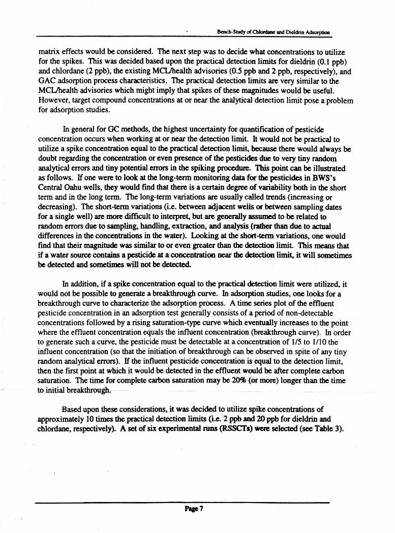
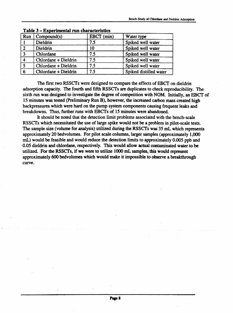
Preliminary RSSCfs were completed in the summer of 1999. Preliminary Run A was set upusing well water spiked with dieldrin and an EBCf of 7.5 min (same set up as Experimental Run1). Preliminary Run B was set up using well water spiked with dieldrin and an EBCf of 15 min.The data collected is shown below (Figures 1 and 2). The reason why this data is calledpreliminary is discussed below.
Figure 1 - Dieldrin breakthrough curve - Preliminary Run A (EBCT 7.s min)
"1000 2000 3000 4000 5000 6000 7000
Bedvolumes Treated (I)
- 2.5.aa.a.-c 2.00
i1.5..-eCD
Co)c 1.00Uc
0.5-.::~
"iis 0.0
0
Figure 2 • Dieldrin breakthrough curve - Preliminary Run B (EBCT 15 min)
2500500 1000 1500 2000
Bedvolumea treated (.)
:c1.2 ...,------:-------------------,a..S: 1.0coi 0.8..-c3 0.6coU 0.4ci 0.2..is 0.0 ~...-_4..._-...__-..........- .....__,---_;
o
Bencb-Studyof ChIordaDc and Dieldrin AdsorpDoa
Figures I and 2 show effluent dieldrin concentration versus bedvolumes of spikedwellwater treated. These curves indicate that the dieldrin breaks through after treating only 2,000 to5,000 bedvolumes. It is not necessary to operate the RSSCfs until complete breakthrough isachieved. Unexpectedly, the RSSCf with the longer EBCf broke through first which is counterintuitive. We are unsure how to interpret this finding which must be assumed to be an artifact.A possibility is that the 15-min EBCf column experienced a failure such that a preferential flowpath was created allowing influent dieldrin to pass through the column without being adsorbedcausing early (apparent) breakthrough. Such a phenomena has not been observed in numerousprevious RSSCfs in our laboratory which accurately mimic full-scale BWS contactors.However, in the previous RSSCfs, less GAC was used and consequently lower backpressureswere observed. The adsorbed mass of dieldrin was about 16 J.LgIg of GAC for Preliminary Run Aand about 5.5 J1g1g of GAC for Preliminary Run B. These results (Runs A and B) weredifficultto explain, so they were considered preliminary and new runs were started. In the late summer,we had some personnel turnover and problems with high-pressure pump seal supply. We wereunable to receive shipment of spare parts that were backordered for approximately 2 months,during which the pump seals leaked so badly that the volume of water treated per day becamevery low.
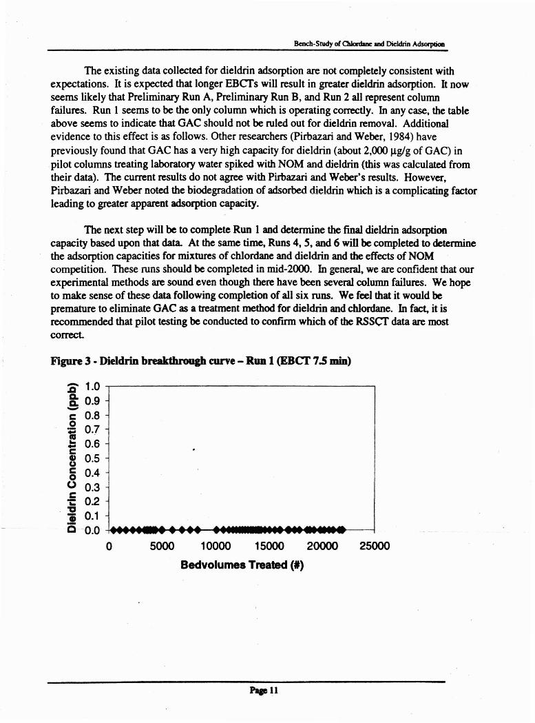
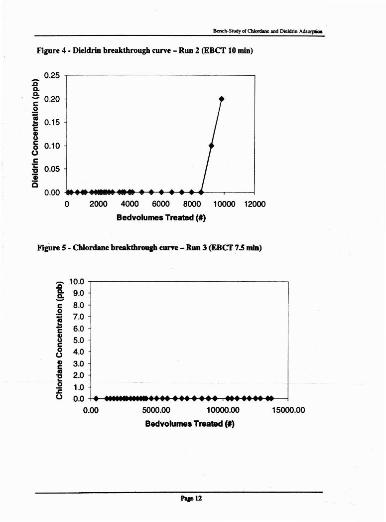
Currently, RSSCfs described in Table 3 as Run I, Run 2, and Run 3 are in progress (seeFigures 3, 4, and 5). Figure 3 shows the Run 1 column (dieldrin, 7.5 min EBCf) which has notachieved breakthrough and has currently treated approximately 22,000 bedvolumes (dieldrinadsorbed = 39 J.LgIg of GAC). Figure 4 shows the Run 2 column (dieldrin, 10min EBen whichhas recently broken through after treating 9,000 bedvolumes (with an adsorbed mass of dieldrinof 21 J1g1g ofGAC). Figure 5 shows the Run 3 column (chlordane, 7.5 min EBCf) which hasnot achieved breakthrough and has currently treated approximately 14,000bedvolumes(chlordane adsorbed = 165 J1g1g of GAC). The same pattern observed in the preliminary runs isbeing repeated in these current runs. The shorter EBCT column (Run I) seems to havea highercapacity for dieldrin than the longer EBCT column (Run 2). It is certainlypossible thata columnfailure occurred for the Run 2 RSSCT (Figure 4) due again to excessive backpressures that wereobserved during the run which could have caused the development of preferential flow paths inthe column. If we assume that full-scale GAC contactors are constructed for treatmentof 1.0mgd of flow, that the influent concentration of dieldrin is 0.2 ppb, and that same massof dieldrinwill be adsorbed to the GAC as observed in the RSSCfs, we can calculate how long thehypothetical full-scale contactors would operate prior to the onset of breakthrough. The existingdata for dieldrin are summarized in Table 4.
T bl 4 E·· data Ii di Id· dso tia e - xistin2 or e nna )11 onRun name EBCT Dieldrin adsorbed Full-scale
(min) . ~ Run time (days)
Prelim. Run A 7.5 16 118Prelim. Run B 15 5.5 81Run 2 10 21 206Run 1 7.5 >39 >286
Page 10
Bench-Study of 0U0rcbne and DieldrinAdsorpcioa
The existing data collected for dieldrin adsorption are not completely consistent withexpectations. It is expected that longer EBCfs will result in greater dieldrin adsorption. It nowseems likely that Preliminary Run A, Preliminary Run B, and Run 2 all represent columnfailures. Run 1 seems to be the only column which is operating correctly. In any case, the tableabove seems to indicate that GAC should not be ruled out for dieldrin removal. Additionalevidence to this effect is as follows. Other researchers (Pirbazari and Weber, 1984) havepreviously found that GAC has a very high capacity for dieldrin (about 2,000 ug/g of GAC) inpilot columns treating laboratory water spiked with NOM and dieldrin (this was calculated fromtheir data). The current results do not agree with Pirbazari and Weber's results . However,Pirbazari and Weber noted the biodegradation of adsorbed dieldrin which is a complicating factorleading to greater apparent adsorption capacity.
The next step will be to complete Run 1 and determine thefinal dieldrin adsorptioncapacity based upon that data. At the same time, Runs 4, 5, and 6 will be completed to determinethe adsorption capacities for mixtures of chlordane and dieldrin and the effects of NOMcompetition. Theseruns should be completed in mid-2000. In general. we are confident that ourexperimental methods are sound even though there have been several column failures. We hopeto make sense of these data following completion of all six runs. We feel that it would bepremature to eliminate GAC as a treatment method for dieldrin and chlordane. In fact, it isrecommended that pilot testing be conducted to confirm which of the RSScr data are mostcorrect.
Figure 3 • Dieldrin breakthrough curve - Run 1 (EBCf 7.s min)
-
:a 1.0 .,.---------------------,a.a. 0.9-c 0.8o; 0.7s_ 0.6eQ) 0.5ua 0.4(J 0.3c"t: 0.2~li 0.1Q -0.0 MM4......~~......._ .....tHI.....>----~
o 5000 10000 15000 zooooBedvolumea Treated (I)
25000
"11
Bench-Study of 0II0rdane and DieldrinA~
Figure 4 • Dieldrin breakthrough curve - Run 2 (EBCT 10 min)
2000 4000 6000 8000 10000 12000
Bedvolurnes Treated (')
0.25-.aa.a.0.20-c
0;
0.15..-cCDuc 0.100oCi: 0.051::J"iC
0.000
FigUre 5 - Chlordane breakthrough curve - Run 3 (EBCT 7.5 min)
15000.00
........................................ '"' ....... '"' .......................,.. .... _.... ..- ,...... .... .... ........ .................................,.
5000.00 OO.00סס1
Bedvolumes Treated (')
:c 10.0 .,---------------------,
8: 9.0-c 8.0o! 7.0C 6.0CDu 5.0c8 4.0! 3.0II"E 2.0
~ 1.0o 0.0 ++-:..........~~~...~.......,rtt~~.....---j
0.00
Pqe12
8cDch·Study of Cblordane and Dieldrin Adsorpboo
4.0 PRELIMINARY CONCLUSIONS AND FUTURE WORK
The preliminary results obtained and the ongoing runs allow the followingpreliminaryconclusions:
• Chlordane and dieldrin are adsorbed onto BWS's GAC in RSSCfs• Some of the RSSCTs conductedwith dieldrinhave not been consistent and probably are
indicative of column failures due to excessivepressure build-up• The GAC capacityfor dieldrin is probablygreater than 39 J.1g pesticideJg GAC• The GAC capacityfor chlordane seems to be greater than 165 J.1g pesticideJg GAC• It would be prematureto eliminateGAC as a treatment methodfor dieldrin and chlordane
As discussed aboveseveral RSSCfs are currentlyunderway and several additional runsare planned. Even though the project period has expired. this additional work will be completed.A graduate student has committed to this work in his prospectus for the Master of Sciencedegree. After completionof the experimental work, a supplemental report will be submitted(expected in mid-2000).
Pap 13
Bench-Study of Chlordane and Dieldrin Adsorption
5.0 REFERENCES
Brown and Caldwell, Inc. (1998) Progress report - technology assessment for chlordane anddieldrin removal.
Crittenden, J.c. et al. (1987) Design of rapid fixed-bed adsorption tests for non-constantdiffusivities. J. Environ. Engr. ASCE 113(2):243-259.
Crittenden, J.e. et al. (1991) Predicting GAC performance with rapid small-scale column tests.J. Amer. Water Works Assoc. 81(1):77-87.
Dearth, M.A., and Hites, R.A. (1991) Complete analysis of technical chlordane using negativeionization mass spectrometry. Environ. Sci. Technol. 25(2):245-254.
Ewald, V. (1998) Study of sorbate competitive behavior and regeneration of granular activatedcarbon (GAC). Master of Science Thesis, University of Hawaii at Manoa, department of CivilEngineering.
EcoIndiana (1998) Aldrin and dieldrin. httj>:/Iwww2.inedtdirect.netl-ecoindy/chemslaldrin.html
EcoIndiana (1998) Chlordane. httj>:/Iwww2.inedtdim:t.netI-ecoindylchemslchlordane.html
Pirbazari, M., and Weber, W.J. (1984) Removal of dieldrin from water by activated carbon. J.Environ. Eng. ASCE 110(3):656-669.
Paae 14
Bench-Study of Chlordane and Dieldrin Adsorption
APPENDICES
I. Standard Curves"
GC Calibration, Dieldrin
70000
6(XXX),......~
~SOOX>"'"~4OOX)--~~3OOX)
U 2!XXXlo
.-
~""",-
-'"~
~io"""'"
~~
.-~......... ""..
30 40 50 60 70 90 100
ImJdrD Coreersraton (ppb)
GC Cahbration, Chlordane
~
..,.,..,.~~ """".-.
~...-- !
I~..,.,..,...-.~
C':S
~ 6(XX)
U 4<XX>o 200:>
oo 100 200y =11.877x + 1274.7
R2 =0.9579
.. 300 400 SOO 600 700
Chlordane ConcentratiJn (ppb)
'.15
800 900 100:>
II. Mini-Column Equipment Set-up
Bench-Study of Chlordane and Dieldrin Adsorption
Page16
Bench-Study of Chlordane and Dieldrin Adsorption
III. Chlordane Chromatogram
SEP 25, 1999 13:44:34
2.125
9 .2499 .574
r
-~~~S;~:'5 .9336.149
6.638\--_ 7.151
7 .573
END Of 51 G t~ A L
Page 17

IV. Mini-Column Scaling Calculations
P.ae II ·
Bench-St1Idy of 0d0nIaDe and Dieldrin Ads~
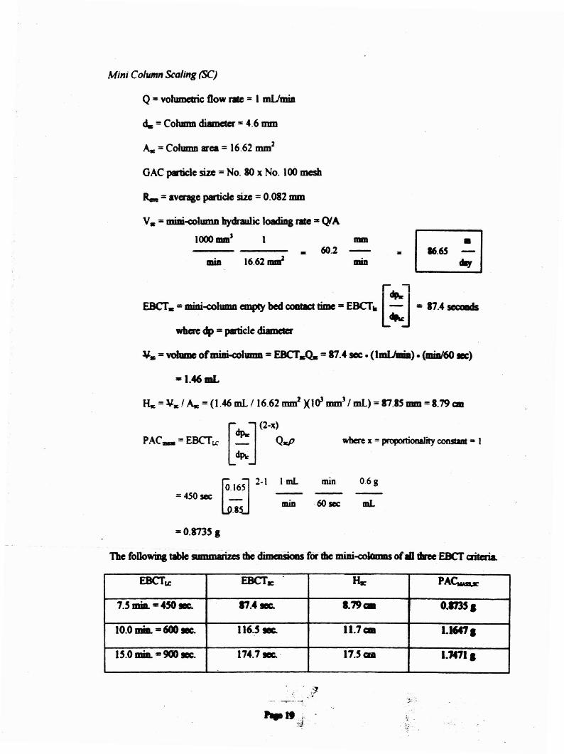
Mini Column Scaling (SC)
Q= volumeuic flow rile =I mUmiD
d. = Column diameter=4.6mID
As= Column area = 16.62 mm2
GAC ,.uc:le size =No. 80 x No. 100 mesh
IIIIIl
60.2•miD 16.62 ".,; .1 •.65 ;1
EBCT. =miDi-<:oluma ""IJlY bed--time =EBCT. [ : J= 17.4........
where dp =p8rticle diameter
R.. = avenge particlesize=0.082 !DID
V. = miDkolmnn hydraulic loadingnile ""~A
1000 mm' 1
¥. =volume ofmiDi-c:ohllllll =EBCTA =81.4 sec· (ImUmia). (mia/60E)
a 1.46mL
As= \til: 1As=(1.46 mL 116.62 mm' )(10' mm) I mL) = 87.15 mm = 1.79 aD
[ J(2-x)
PAC_=EBCT>e ~ Q.p where x = proportionality constant "" I
~. 16J 2-1
=4S0sec _
.8
ImL
min
min
60 sec
0.6 g
mL
=O.873S g
ThefoDowDla tabte anDmaliz.es diedimalSiODS forthe miDi-<:okmms of10 line EBCT criteria.
EBCTLe EBCTsc Hte PA~
1.5miD. ,.. 450 lee. 11.41eC. l.79c:. 0.1735,
10.0 mill. =600 E. 116.51& 11.1ca 1.l647.
lS.Omia. -900 E. 114.11& ' 17.Saa 1.7471,
,.It ,i:d .
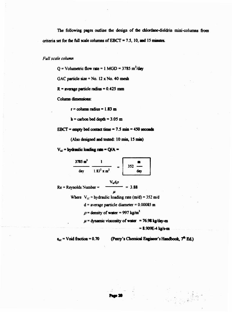
The foUowiDg pages outline the design of the c:IaIordIDMiddrin mini-<:olunms &om
criteria set for !be fUD scale c:ohmms ofEBCT -7.S. 10," I' IIIiaUs.
FilII scale collllJlll
Q = VoIUlDdric: Oow J'Ite= I MOD =3785m)/ay
GAC particle size =No. 12 x No. 40 mesh
R=avcnp pmide radius =0.425 !DID
r = coIumD radius := 1.13 m
h =c:arboa bed dcpda = 3.05 m
EBCT =emptybod CQIIta:I time=7.S miD =4~ IDPiMs
VLC=~ kwh. r-. - f;NA-
3715 ,,;
Re = Reynolds Sumber = --- = 3.88II
Where Vu: =hydraulic loading rate (mid) = 352 mid
d = average partic:le diameter =0.00085 m
p =density ofWIler =997 qlmJ
P =dynamic viscosity of.... ,.. 76.91 k&/day-m
=1.909E~ qtHII
fu =Void fiactioIl =0.70
,... , ..- ..' -
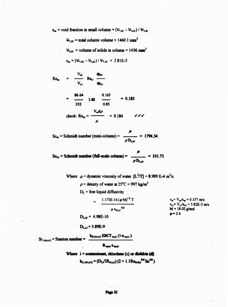
ewe .. void fraction in smaIl colUIDD =(\trx - ¥s.r) /lJu:
¥r.JC =toeaI column volume =1460.1 mm)
¥u: .. volume of solids in cohDDn =14S6mm)
=16.64 0.165
3.11 . = 0.115352 o.•s
VadPcllcd: Res = -- = 0.184
JI
Scs =SdImidt Dumber (mini-e:oIUlllll) =/I
-_ ... 179t.34
/I__ ,. 151.71
VIC= v.!&rc = 0.357 m/svu:=V~ = S.82E-3·m/sMa 18.02w'moI.,- 2.6
I>Lr = 4.9IE-I0
Due= 5.89£-9
Where ~ = dynamic viscosity ofwllla' [L2f11 = 1.909E.... m2/s
p =density of water It 2SoC =m kgIm)
Dt. =free liquiddiffusivity
= 1.173E-16 (qIM)I '2 T
ka(K,&.C) EBCT-...c (I.-.u: )51 i (-...c) =Stantoll !IQIDIJer ,.
Il-...:I-...:
Wben i =COO'w"j.._. c:*bdIDe(e) or ...5dh.(4
ko(.-.&oC)"~ (2 + 1.1~"ScIS)
"21
r
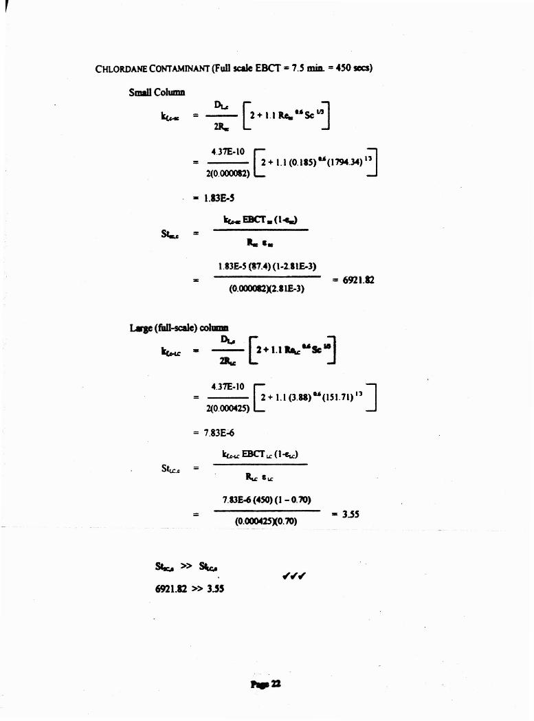
CHLORDANE CONTAMINANT (Full scale EBCr =7.S miD. =..SO sees)
SIDI1l Column
k,... = ~ [2+1I ......SC ..J4.31£-10 ~ :J= 2 + l.l (0.18S) U (1794.34) 13
2(0.0000I2)
= 1.13E-5
kt.- E8CT. (1~
=
....1.13£-5 (11.4)(1-2.11£-3)
(O'()OO082X2.llE-3)=6921.12
4.31£-10 ~ ]= 2 + 1.1 (3.88) U(1SI.71) 11
2(0.000425)
= 7.83E~
Slu:.c =
=7.I3E~(4SO)(1-0.70)
(O.OOO425XO.70)= 3.55
sa.:.. » St..c..
6921.12 » 3.55
,.22
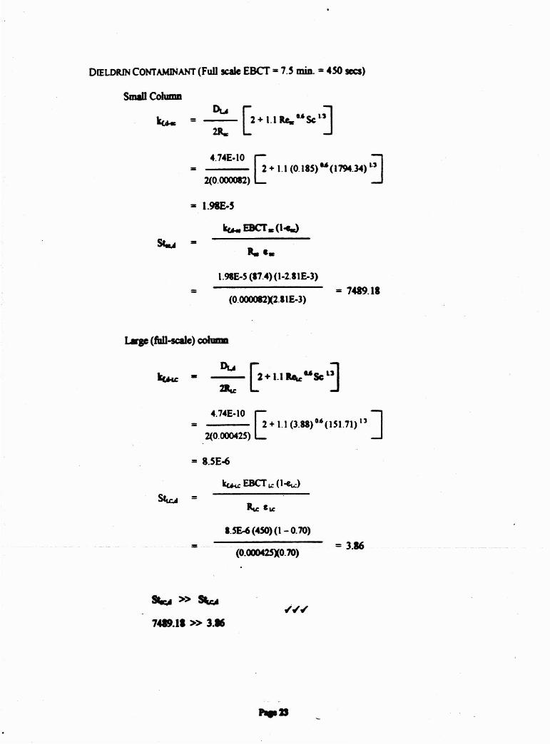
DIELDRIN CONTAMINANT (Full~ EBCT = 7.S min. = 4SO sees)
Small Column
ku.. = :: [2+11 ....USC'~4.74E-I0 ~ ~= 2 + 1.1 (0.18S) U (1794.3<4) ..,
2(0.4)00082)
= 1.98£.S
kue EBCT. (I-e.)
=I.98E-5 (17.4)(1 -2.I1E-3)
(O.OOOO82X2.IIE-3)= 7489.11
Lqe (fall-scale) coIuma
4.'4E-I0 ~ ]= 2+1.1 (3.88)G.6(151 .'I) 13
2(0.000425)
= I.SE~
~EBCTlo:(l~)
Stu:A =
=1.SE-6(450)(1-O.70)
(O.oOo42SXO:70)= 3.16
~ » S\c"
7419.11 » 3.•
"23
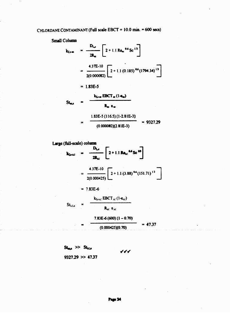
CHLORDANE CONTAMINANT (Full scale EBCT = 10.0miD.. = 600 sees)
Small Column
=
4.37E·IO ~. ~= 2 + 1.1 (0 .18S) u(I794.3"') I·'2(0.()()()()82)
= I.83E-'
ke- EBCT. (l-c.J
=
R. ••
1.:3£-5 (116.5) (1-2.81£-3)
(0·OOOO82X2.81E-3)= 9321.29
4.37E-IO ~ ]= 2 + 1.1(3.88) G.6(lS1.71) IJ
2(0.000425)
= 7.83E-6
ku-u: EBCTt.C (I-f:t.c)
Sltc.c: =
=7.83E~(600)(l-0.70)
(O·OOO42SXO.70)= 41.31
St.u » Stu:..
932729 » 47.37

DIELDRIN CONTAMINANT (Full scale EBCT=10.0 min. =600 sees)
Small Column
4.74E-10 ~ :J= 2 + 1.1 (0.185)0.6 (1794.34)1)
2(0.()()()()82)
= l.98E-S
kucEBCTIC(I~
=i.98E·5 (I 16.5) (1-2.81£-3)
(0.clOO082X2.IIE-3)= 9912.12
Large (full-scale) column
~ - :: [z+I.\ ......Sc~4.74E-10 ~ ]= 2 + 1.1 (3.88)"(151.71) 11
2(0.000425)
= 8.SE-6
Stu:..t =
=
SIc" » ~
9912.72 » 5.14
8.SE~(600)(1-0.70)
(0.c)OO425XO.70)= 5.14
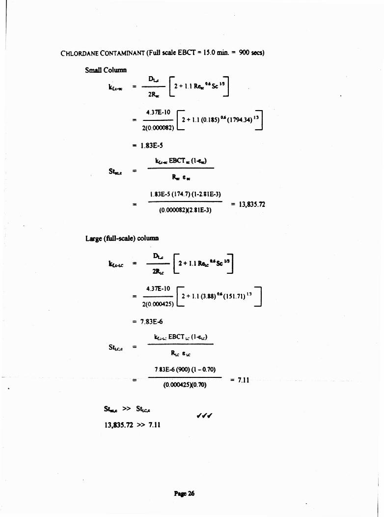
CHLORDANE CONTAMINANT (FuU scale EBCT:= l~.O min. = 900 sees)
Small Column
= --- ~+ II Ro,,"Sc:'~
= 4.37E-IO r;+1.1(O.18S)G.6(1794.34)I~2(0.000082) L..: J
= 1.83E-S
~c EBCT Ie(l~
St.e.c =
=i.13E-S(i74.7) (1-2.81&3)
(0.000082)(2.81E-3)= 13.83~.n
Large(fWl-scale) column
= 4.37E-IO r;+ 1.1 (3.18)11.6(151.71) 13 ]
2(0.000425) L..:
= 7.83E~
ktx.: EBCT L.: (I-€u:)
StLC.C =
=783E-6 (900)(1 - 0.70)
(0.000425)(0.70)= 7.11
~ » Stu:.e
13.83S.72 » 7.11