behavior and scenario modeling for real-time virtual environments
TRANSCRIPT
BEHAVIOR AND SCENARIO MODELING
FORREAL-TIME VIRTUAL ENVIRONMENTS
by
PeterJasonWillemsen
An Abstract
Of a thesissubmittedin partialfulfillment of therequirementsfor theDoctorof Philosophy
degreein ComputerSciencein theGraduateCollegeofTheUniversityof Iowa
May 2000
Thesissupervisor:ProfessorJosephK. Kearney
ABSTRACT
Virtual environmentsprovideapowerful mediumfor studyinghumanbehavior. To
exploit thepotentialof virtual environmentsaslaboratoriesfor psychologicalexperimen-
tation,wemustbeableto controlthedynamicsof complex virtual environmentspopulated
with autonomousentities. In experiments,the right thingsmusthappenat the right time
andplace.
My researchaddressestwo essentialcomponentsrequiredto createengaging,real-
time, virtual environments: (1) Representationsof the physicalenvironmentadaptedto
theneedsof autonomousbehavior programmingin urbansettings,and(2) An interpreted
scriptinglanguagefor onlineprogrammingof scenariocontrolprocesses.
I introducethe EnvironmentDescriptionFramework (EDF) andthe ScenarioDe-
scription Language(SDL) aspartsof an integratedsystemto addressintertwinedprob-
lemsof modelingbehaviors andscenariosin structured,urbanenvironments. We create
autonomousbehaviors thatmodelthedynamicentitiescommonlyfoundin theseenviron-
ments:traffic lights,motorists,bicyclists,andpedestrians.We usethesameframework to
modelscenariodirectorsresponsiblefor orchestratingtheactionsof multiple,autonomous
behaviors.
The EDF definesa road and intersectionbasedrepresentationthat supportspro-
grammingof autonomousagentsin real-timevirtual environments.As its corefunction,
v
EDF givesstructureandmeaningto physically-basedcomponentswhile overlayinglog-
ical and spatial relationshipinformation on the geometricstructureof the environment.
Our environmentmodelis distinctin thatit embedsbehavioral constraintsandinter-object
relationshipsinto theenvironmentstructure.
SDL is usedfor interactivemodelingandprototypingof scenariodirectorsin real-
timevirtual environments.SDL is aninterpretedscriptinglanguagethattranslatesscenario
directivesinto statemachineswhich aretheninsertedinto thesimulationexecutionframe-
work. SDL advancesstandardscripting languagesby clearly separatingstatementsthat
describewhathappensfrom statementsthatdeterminewhenthingshappen.SDL is tightly
boundto simulationactivity andforms a glue betweenthe EDF, autonomousbehaviors,
andthescenariodirectorsthatinfluencetheenvironment.
vi
30
CHAPTER 4ENVIRONMENT DESCRIPTION FRAMEW ORK: AN INTERFACE TO THE
WORLD
This chapterdescribesthe EnvironmentDescriptionFramework (EDF). The EDF
modelsroadnetworksby defininga road-basedrepresentationthatsupportsprogramming
of autonomousagentsin real-timevirtual environments. As its core function, the EDF
givesstructureandmeaningto physically-basedcomponentswhile overlayinglogical and
spatialrelationshipinformationon thegeometricstructureof theenvironment.
The purposeof the EDF is to efficiently model the geometric,topological,and
logical information requiredby programsthat codeautonomouspedestrianand vehicle
behaviors. The EDF databaseis alsousedby scenariocontrol programsthat orchestrate
behaviors to createpredictableexperiencesfor participants.
Thestructuresin theEDFarebasedonthenatureandfunctionof realroadnetworks
in urbanenvirons. In therealworld, driving is highly regulated;laneschanneltraffic into
parallelstreams,signspostedalongsidethe roadsignify importantchangesto our behav-
ior, andlinespaintedon thesurfacedictatewhetherlateralmovementis prohibited,or not.
Roadnetworksareformedwhereroadsconnectto intersections.Realintersectionsarenot
free-for-alls; entranceinto andmovementthroughintersectionsis regulatedandcontrolled.
Intersectionsroute incoming lanesto outgoinglanesvia naturalcorridors. As humans,
we have exceptionalapparatusfor perceiving thesecorridorsandunderstandingthecom-

31
plex relationshipsthat stemfrom usingthem. Right of way conventionsordermovement
throughintersections.Traffic controlmechanisms,suchastraffic lights, explicitly control
entranceto theintersection,oftenon a lane-by-lanebasis.All in all, movementover roads
and intersectionsin everydaylife is controlledby well-definedstructures,societalrules,
andautomatedregulationmechanismsto minimizecongestionandaccidents.
Theorganizationof theEDF is highly influencedby thebehaviors usedto control
autonomousagents. In this regard, the EDF is behavior-centric. The key to this orga-
nizationcomesfrom an understandingof what information, in additionto geometryand
topology, is neededby the autonomousagentsin the environment. Throughthis organi-
zation,theEDF emphasizesa strongcouplingbetweenbehavior andenvironmentalstruc-
ture. In essence,behavioral implicationsarefurnishedby the environmentalstructureto
assistautonomousagentdecisionmakingprocesses.The couplingbetweenbehavior and
environmentis centralto ecologicalpsychology. J.J.Gibsonintroducedthe ideaof envi-
ronmentalaffordancesfor behavior. He assertedthat humansperceive muchmore from
theenvironmentthanbasicsensoryinformation.He arguedthattheenvironmentprovides
humanswith contextualandrelationalinformation[28][56]. In asimilar sense,mostman-
madestructures,suchasroadsandintersections,aredesignedto administeraspecificlogic
andorderto ourbehavior. I believethattheseprinciplesanddesignconsiderationsserveas
excellentmotivationandreferencefor constructingboththeenvironmentalframework and
theinteractive,autonomousbehaviorswithin thevirtual environment.
TheEDF definesstructural,logical, andrelationalpropertiesin thedatabasecom-

32
ponentsto integratebehavior andenvironmentrepresentations.Structuralcomponentspro-
vide detailedgeometricandtopologic information. For instance,roadsandintersections
representstructuralcomponents.Theroadsurfaceis composedof purelygeometricrepre-
sentationformingtheso-calledpavementof theenvironment.Intersectionshaveshapeand
definea boundary. Roadsconnectto intersectionsalongthis boundarycreatingthe road
network topology.
Logicalattributesdescribetheculturally importantandsociallyresponsibleaspects
of the urbanenvironment. For the mostpart, thesepropertiesinfluencethe autonomous
agents’actionswithin theconfinesof theEDF’s structuralcomponents.Lanes,lanelines,
roadsidefeatures,intersectioncorridors,andtraffic controlmechanismsall representlogi-
cal aspectsof theEDF.
In the EDF, relationalcomponentsdescribespatialandinter-objectadjacency in-
formation. In addition,relationalcomponentsareusedto link importantbehavioral rela-
tionshipswith context-dependentbehavior. Occupancy information is calculatedby the
simulationandstoredin theEDF to spatiallylocatetheautonomousagentswith respectto
thestructuralcomponentsof theEDF. Adjacency is definedin termsof which objectsare
in front of, behind,or next to thenearbyautonomousagents.Corridordependenciesmark
importantintersectionrelationshipson acorridor-by-corridorbasis.
Thetreatmentof intersectionsin theEDF illustratesoneaspectof how theseprop-
ertiescombineto form the EDF’s components.Intersectionsarenotoriouslydifficult to
model,bothgeometricallyandbehaviorally, in driving simulations.Roadsinterconnectin
33
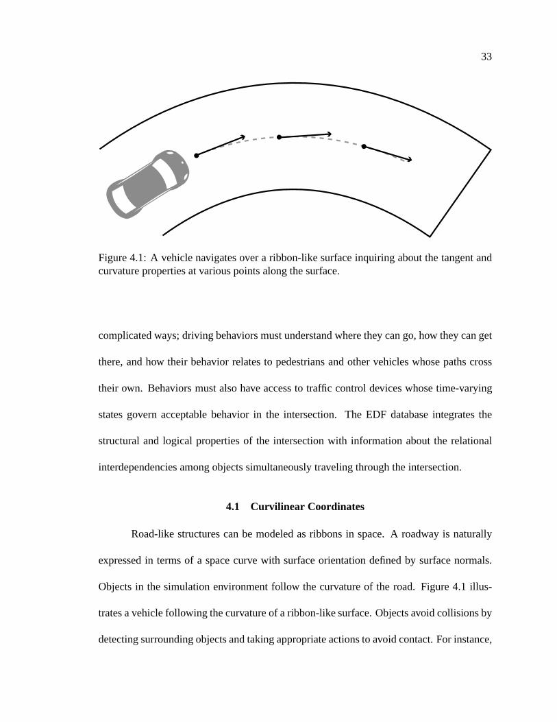
Figure4.1: A vehiclenavigatesover a ribbon-like surfaceinquiring aboutthetangentandcurvaturepropertiesat variouspointsalongthesurface.
complicatedways;driving behaviorsmustunderstandwherethey cango,how they canget
there,andhow their behavior relatesto pedestriansandothervehicleswhosepathscross
their own. Behaviors mustalsohave accessto traffic controldeviceswhosetime-varying
statesgovern acceptablebehavior in the intersection. The EDF databaseintegratesthe
structuraland logical propertiesof the intersectionwith informationaboutthe relational
interdependenciesamongobjectssimultaneouslytraveling throughtheintersection.
4.1 Curvilinear Coordinates
Road-like structurescanbe modeledasribbonsin space.A roadway is naturally
expressedin termsof a spacecurve with surfaceorientationdefinedby surfacenormals.
Objectsin the simulationenvironmentfollow the curvatureof the road. Figure4.1 illus-
tratesavehiclefollowing thecurvatureof aribbon-likesurface.Objectsavoid collisionsby
detectingsurroundingobjectsandtakingappropriateactionsto avoid contact.For instance,
34
vehiclesstaywithin the lanesof roadsandslow down to avoid collisionswith objectsin
front of them. Pedestriansdodgeandweave aroundnearbypedestrianson crowdedside-
walks.
Thedriving surfacein theEDFis describedby areferencecurve in 3D spacewith a
surfaceextendingoutward,awayfrom thecurve. Waypoints,features,andobjectpositions
areall locatedrelativeto thissurface.Elevation,curvature,tangent,andsurfacenormalsare
importantsurfaceorcurvefeaturesthatareembeddedin thesurfacedescription.Thevalues
of theseattributesmaychangeasa functionof surfaceposition.For example,curvatureat
onepoint on thesurfacemaynot be thesameascurvaturejust a small distanceaway. In
general,theinformationneededby autonomousbehaviors is oftendependenton structural
context andlocationon theroadsurface.
Roadsurfacesin theEDFarerepresentedin curvilinearcoordinatesystems. Curvi-
linearcoordinatesprovideanaturalmeansfor describingpositionsandrelativelocationson
theroadsurface.A curvilinearcoordinatesystemis a two-dimensionalcoordinatesystem
basedona three-dimensionalreferencecurve thatactsasthemajoraxis.Theminor axisis
definedasthevectorperpendicularto themajoraxisandthesurfacenormal.
The curvilinearcoordinatesystemusedin the EDF definesthe first dimensionas
distance(�) andtheseconddimensionasoffset( � ). Distanceis measuredasthearc-length
alongthe referencecurve. Offset is givenby the shortestdistanceto the referencecurve
asmeasuredlinearly alongtheminor axis. A singlecurvilinearcoordinateis describedby
thepair � ��� ��� . Usingthissystem,pointson thesurfacecanbeuniquelylocatedwith botha
35
reference curve major axis (distance) minor axes (offset)
(δ2,ο2)
(δ1,ο1)
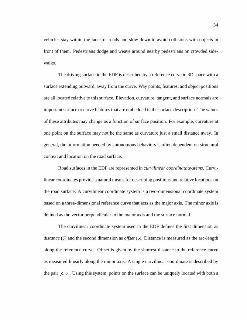
Figure4.2: Illustrationof acurvilinearcoordinatesystem.Two curvilinearcoordinatesareshown depictingdifferentlocations.
distance(�) andanoffset( � ) parameter.
Coordinatesonacurvilinearsurfacearedefinedfrom anorigin, which is definedas
the startinglocationof the referencecurve. At this location,both distanceandoffsetare
zero. Offsetswith positive valuearelocatedto the left of the referencecurve andoffsets
with negative valuearelocatedto the right (whenviewed in the positive directionof the
majoraxis). A curvilinearcoordinateframeis illustratedin Figure4.2. Thedistanceand
offset measuresdefineorderingrelationsfor objectson the surfacethat arethe basisfor
determiningspatialrelationshipsof objectson roadsin theEDF.
Curvilinearcoordinatesareusedin theEDF databaseasa basisrepresentationfor

36
all navigableroutes.Behavioral objects,suchasvehiclesandpedestrians,trackcurvilinear
coordinatesto follow roads,lanes,androutesthroughintersections.In Chapter3, I men-
tionedthatoneof thepotentialresponsibilitiesof theautonomousbehaviors is to provide
control inputsto physics-based,dynamicsmodelsof theobjectsthey control. At timesit
is beneficialfor behaviors to computecontrol inputsin termsthat areconsistentwith the
dynamicsmodelscontrollingtheobject.Most dynamicsmodelsareexpressedin termsof
Cartesiancoordinates,and thus,produceCartesianpositions,ratherthancurvilinearpo-
sitions. Therefore,it is necessaryto provide conversionsbetweencurvilinearcoordinates
andCartesiancoordinates.Theseconversionsareanessentialpartof all curvilinear-based
componentsin theEDF.
Givena � ��� ��� pair, any curvilinearcoordinatesystemin theEDFdatabaseneedsto
becapableof transformingthecoordinateinto a Cartesiancoordinate,asexpressedby the
EDFquery
��! #"%$'&�(*),+�-/.10 �2� ��� �3�,�This query takesas input a curvilinear coordinateandreturnsa Cartesiancoordinatein
three-space.
Oncethedynamicsprocesshascalculateda new Cartesianposition,we mustmap
the position back to curvilinear coordinates. In EDF, the transformationfunction from
Cartesianto curvilinearcoordinatesis
� ��� �3� "%$4&5(*),+6-87:9 � �� �
whichconvertstheinputparameter�
into acurvilinearcoordinate� ��� �3� onthecurvilinear

37
coordinatesystemrequestingthetransformation.
Theability to convert coordinatesfrom Cartesianto curvilinearspaceis important
atothertimesaswell. Whenobjectsareinitially placedin thesimulationenvironment,it is
ofteneasierto positiontheobjectsaccordingto absoluteCartesiancoordinatesratherthan
curvilinearcoordinates.Oncein theenvironment,theobject’s locationcanbeconvertedto
curvilinearcoordinatesusingtheprovidedqueries,asneeded.
For road-basedbehaviors, curvilinear coordinatesare extremelyuseful: (1) they
naturallyrepresentlocationsalonga road-likesurfacethusfacilitatingroadandlanetrack-
ing behaviors, (2) relative spatial locationsare easily definedwith respectto the curve
which is instrumentalfor following and obstacleavoidancebehaviors, and (3) conver-
sionsbetweencurvilinearandCartesiancoordinatesafford flexibility in programmingau-
tonomousagentsasdifferentcoordinatesystemscanbeusedfor differentpurposes.
4.2 Segments- The PavementUnder Our Feet
In therealworld, whenconstructioncrews build new roadwaysthey first gradethe
roadandthenlay pavementwherethenew roads,or intersections,will exist. At thisstagein
construction,only thesurfacegeometryis defined.In theEDF, drivablesurfacegeometry
is representedby basicstructurescalledsegments.
EDF segmentsareanalogousto the pavementof real roadnetworksandareused
to modelfixedwidth stretchesof road.EDF segmentsarerepresentedwith curvilinearco-
ordinatesystemsto providegeometricandstructuralinformationaboutthesurface.While
segmentwidth is constant,the extent neednot be symmetricaboutthe curvilinearrefer-
38
Reference Axis
l;eft width (positive offset)
r< ight width (negative offset)
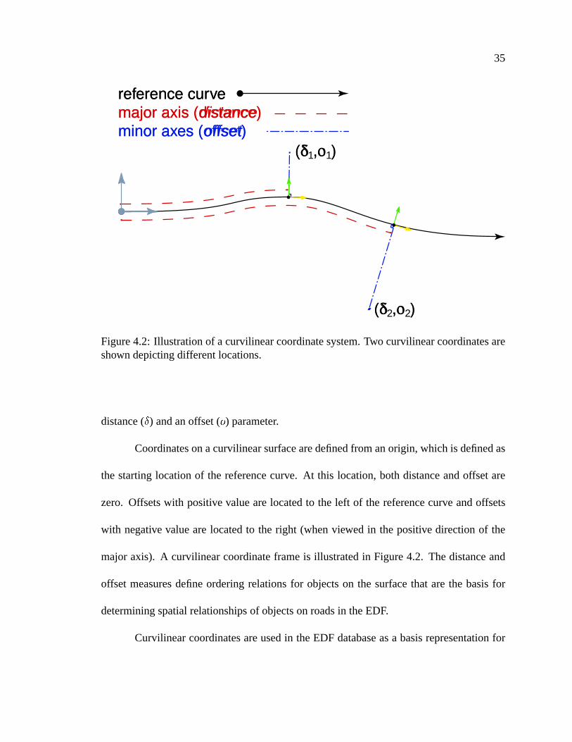
Figure4.3: Illustrationof generalsegmentproperties.
enceaxis.Figure4.3illustratesabasicEDFsegment.Segmentsarestructuralcomponents
thatsupportcurvilinearcoordinatetransformations,aswell asgeometricqueriesaboutthe
curvilinearsystemandsurface,includingcurvature,tangent,elevation,andsurfacenormal.
Usinga varietyof segments,we areableto createroad-like structuresin theEDF
on which vehiclesand pedestrianscan drive and walk. For instance,we can construct
linear segmentsfor representingstraightroadsand cubic segmentsfor representingthe
surfacedescriptionsnecessaryfor curvedpaths.In general,wecanconstructmany different
ribbon-likesegmentdescriptionseachfor representingdifferentroadsurfaces.For themost
part,theroadswemodeldonot twist violently or turnupsidedown. However, becausethe
surfaceis definedby the referencecurve’s normalvectors,EDF segmentscaneasilybe
usedto representsurfacesthatexhibit extremetwist, suchascanbefoundonroller coaster
tracks. Nonetheless,our concentrationis on urbandriving environmentswhere,for the
mostpart,theroadnormalspoint skyward.
Becausethe segmentis basedon a curvilinearsystem,surfaceattributes,suchas
39
float"%$
length()Returnsthetotal arc-lengthof thesegment.
float"%$
width( [ left or right ] )Returnstheleft or right width of thesegment.
float"%$
elevation( � ��� ��� )Calculatessurfaceelevationat (
��� � ) on thesegment.float
"%$curvature( � ��� �3� )
Calculatescurvatureat (��� � ) on thesegment.�� "%$
tangent( � ��� �3� )Calculatesthetangentvectorat (
��� � ) on thesegment.��! ="%$normal( � ��� �3� )
Calculatesthesurfacenormalvectorat (��� � ) on thesegment.
� ��� ��� ">$ queryXY(��
)Convertsfrom Cartesianto curvilinearcoordinates.��! ="%$
queryDO( � ��� ��� )Convertsfrom curvilinearto Cartesiancoordinates.
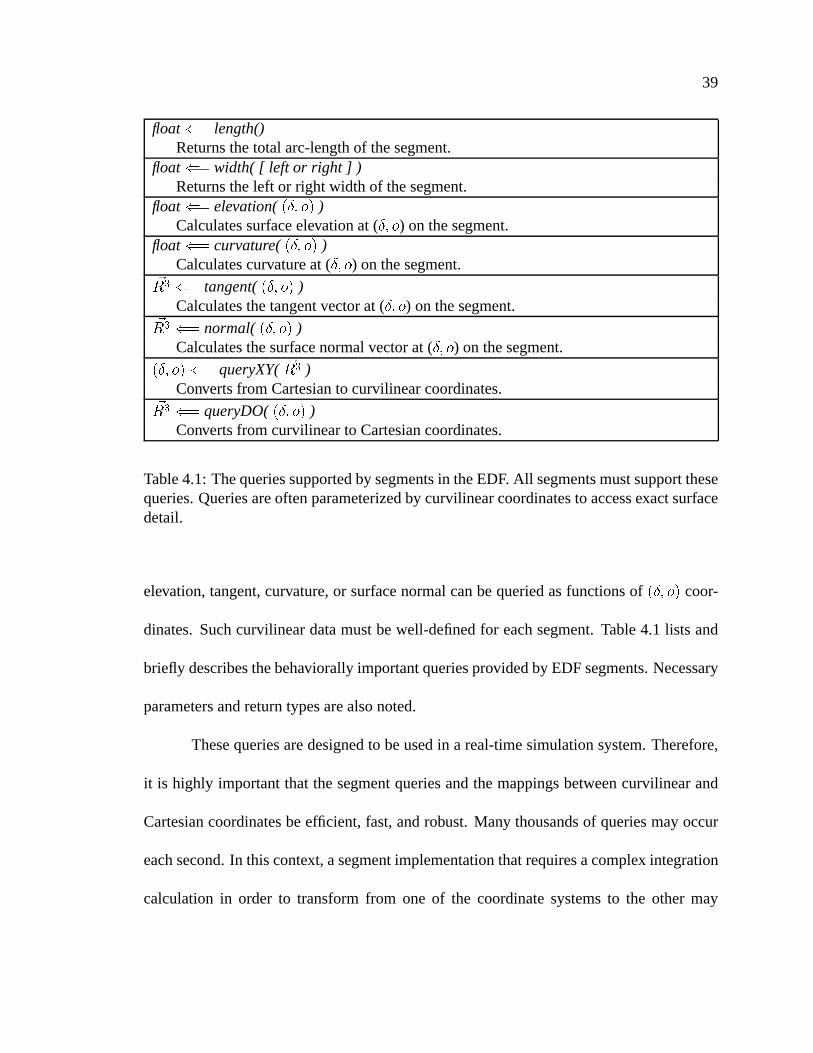
Table4.1: Thequeriessupportedby segmentsin theEDF. All segmentsmustsupportthesequeries.Queriesareoftenparameterizedby curvilinearcoordinatesto accessexactsurfacedetail.
elevation,tangent,curvature,or surfacenormalcanbequeriedasfunctionsof � ��� �3� coor-
dinates.Suchcurvilineardatamustbewell-definedfor eachsegment.Table4.1 lists and
briefly describesthebehaviorally importantqueriesprovidedby EDFsegments.Necessary
parametersandreturntypesarealsonoted.
Thesequeriesaredesignedto beusedin a real-timesimulationsystem.Therefore,
it is highly importantthat thesegmentqueriesandthemappingsbetweencurvilinearand
Cartesiancoordinatesbeefficient, fast,androbust. Many thousandsof queriesmayoccur
eachsecond.In thiscontext, asegmentimplementationthatrequiresacomplex integration
calculationin order to transformfrom one of the coordinatesystemsto the other may

40
S?
egment 1
S?
egment 2 S?
egment 3
S@
4 S@
5 S5
S4Segment 3
SegA ment 2
S@
egment 1
Figure4.4: An illustrationof a hierarchicalsegmentin theEDF. Thecompletesegmentiscomposedof threeleaf segments[S4, S5, Segment3]. SegmentsSegment1andSegment2areparentsegments.
be too computationallyexpensive. In any case,it is importantthat speed,efficiency, and
robustnessbebalancedfor segmenttypesusedin theEDF.
4.2.1 Compositing- HierarchicalSegmentDescriptions
It is usefulto combinesegmentdefinitionsto form largeraggregates.Segmentsin
theEDF canbecomposedof othersegmentsforming hierarchicalcurvilinearsurfacede-
scriptions.Parentsegmentsassembleandmanagechild segmentsto transparentlypresent
a singleEDF segmentinterface. In otherwords,a singlecurvilinearcoordinatesystemis
mappedacrossa the leaf segments.Figure4.4 illustratesthe hierarchicalstructurefor a
simplesegmentcomposedof threeleaf segments.
Hierarchicalsegmentsarecontinuousat the joins of adjacentsegments.With re-
gardto theconnectionbetweenadjacentsegments,we definecontinuousto meanthat (1)
connectingsegments’endpointsbecoincident,(2) adjacentsegments’widthsareidentical
on bothpositive andnegative sides,(3) adjacentsegments’referencecurvesalign with at
least � � continuity1, and(4) surfacenormalsat the joining edgeof the two segmentsare1 B � continuity requiresa commontangentat the joining point of the two segmentsand B �
continuityrequiresthatthecurvaturebecommonat thejoining pointof thetwo segments.

41
identical. Theserestrictionsensurethathierarchicalsegmentsremainribbonlike in curve
andsurfacedefinitions.
4.2.2 Segmentsin theEDF
EDF segmentsareusedto modelboth geo-specificandgeo-typicalroadways. In
the real-world, road designersconstructmodernhighwaysusing standardtechniquesof
civil engineering.However, many older roadsare not built to conform to any standard
designcriteria.UsingtheEDF, wecanmodelmany differenttypesof roadwaysusingcivil
engineeringdata,or morefree-formopen-endeddesigncriteria.
To matchcivil engineeringdesignstandards,theEDFdefinesthreesegmentsbased
on analyticexpressionsusedin roadway design.Thesearethestraight, curve, andspiral
segments[3, 23]. Thesesegmentsaredescribedanalyticallyandmodelsmoothlychanging
curvatureand superelevation requiredon high-speedroadways. When compositedto-
getherin theEDF thesesegmentscanbeusedto accuratelymodelmany real-world roads.
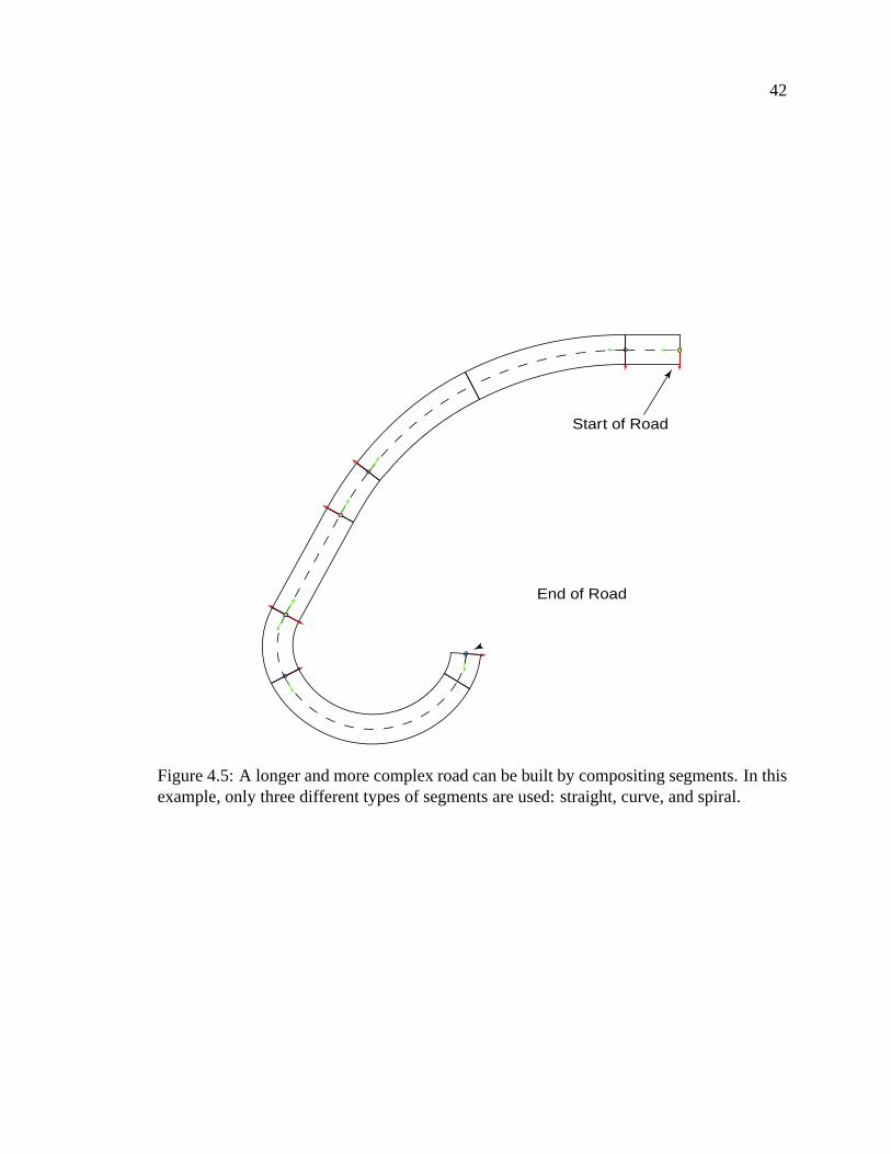
Figure4.5 illustrateshow a curvedroadwould berepresentedin theEDF usinga combi-
nationof thesesegments.Becauseof their analyticnature,thesesegmentsafford fastand
efficient queriesfor surfacecharacteristicinformationandcurvilinearcoordinatesystem
transformations.
4.2.2.1 StraightSegments
As seenfrom anorthographicprojectionontothegroundplane,straightsegmentsin
theEDFconnecttwoCartesiancoordinatesin spacewith aline. Surfaceelevation,andthus,
42
Start of Road
End of Road
Figure4.5: A longerandmorecomplex roadcanbebuilt by compositingsegments.In thisexample,only threedifferenttypesof segmentsareused:straight,curve,andspiral.

43
surfacenormal, is controlledby a separatefunction of�
that basesheighton a parabolic
curve. In theEDF, straightsegmentscanbespecifiedwith eithertwo, or three,Cartesian
coordinates.When two coordinatesare defined,the segmentsurfaceis flat, with linear
changesin.
,0
, and C coordinates.Whenspecifiedusingthreecoordinates,thestraight
segment’s elevation (heightin C ) is determinedby fitting a parabolathroughthe three Ccoordinates.Two-dimensionaltangentvectorsalongastraightsegmentareconstant,while
curvatureis alwayszero.
4.2.2.2 CurveSegments
Curvesegmentsdefinearibbon-likecirculararcwith C dependenceidenticalto the
straightsegment.In otherwords,acurvesegmentsurfacehasconstantcircularradius(con-
stantcurvature)andsweepsout anarcof constantradius.If only thetwo endcoordinates
of thearcarespecifiedthanthechangein theelevation( C ) is linearwith respectto length
along the curve. By specifyinga third coordinate,we canfit a parabolato the segment
describingsurfaceelevationasafunctionof distancealongthecurve. Curvesegmentsmay
alsodefinea constantsuper-elevationwhich specifiestheamountof banking.Surfaceele-
vationatapoint is determinedasby combiningthesurfaceheightwith thesuper-elevation.
4.2.2.3 SpiralSegments
Spiral segmentsprovide a transitionbetweenstraightandcurve segments.Spiral
segmentssmoothlyinterpolatebetweenthe zerocurvatureandzerosuper-elevation of a
straightsegmentto thefixedcurvatureandsuper-elevationof acurvedsegment.Theeleva-

44
tion of thespiralsegmentis determinedby combiningsuperelevationwith surfaceheight.
Thesurfaceheightof thespiral is calculatedidenticallyto thestraightandcurve segments
with eithera linear interpolatedprofile or a parabolicelevationprofile runningthe length
of thesegment.
4.2.2.4 GeneralizedCubicSegments
At times, it is moreconvenientandeasierto model roadsin a free-formmanner
thanby adjoininganalyticalsegments.Free-formroadconstructionis useful for quickly
prototypingscenesusingintuitivecurvedrawing techniques.Moreover, many roadsin the
real world arenot constructedaccordingto standardengineeringdesignpractices.In the
EDF, free-formroadmodelingis handledby ageneralizedcubicsegment.A cubicsegment
is describedby asetof D interpolatingpointsin�
.
E�F � F � �HGHG�GI� F �� ��,JTo facilitate transformationsbetweencurvilinear and Cartesiancoordinatesystems,we
must reparameterizethe cubic segmentso that it is parameterizedby arc-length. Once
thesegmentis parameterizedby arc-length,curvilinearcoordinatescanefficiently becon-
vertedto Cartesiancoordinatesby performingbinary searchesusingcurvilineardistance
asthekey over thesamplingpoints,calculatinglocalizedcubicevaluations.Determining
curvilinearcoordinatesfrom Cartesiancoordinatecanalsobedifficult. Weuseuseasmall
numberof stepsin a Newton’s methodto efficiently handleconversionfrom Cartesianto
curvilinearcoordinates.
In summary, EDF segmentsprovide the foundationfor modelingroad surfaces.

45
EDF segmentsarecurvilinearcoordinatesurfacesthat analogousto ribbonsof pavement
throughthe environment. Segmentsprovide queriesfor interrogatingthe surfaceinfor-
mationandconverting betweenlocal curvilinearcoordinatesandCartesianspace.Using
hierarchicalcomposition,segmentscanbecombinedto form moreelaboratepathwaysthat
mimic theconstructionstyleof roadsfoundin therealworld.
4.3 Roads
Oncethepavementfor a new roadis set,constructioncrews paint lanelineson the
roadsurfacethatdelineatelanestructure.Laneslinesalsoidentify regulationson driving
activities, suchaspassing.Signsareplacedalongsidethe roadto signify speedlimit, no
parking,merges,andyields.Thelanelinesandsignagerepresentlogicalaspectsof driving.
Humanscaneasilydrive over pavement,but order, andthusbehavior, is determinedfrom
the logic appliedto the road. In the EDF, roadsaremodeledvery similarly by applying
logic andorderto a segmentrepresentingthepavement.
Roadsin the EDF arecomposedof a segment,which may be hierarchical,a lane
profile definition, andfeaturedescriptions.The road’s segmentdefinition representsthe
pavementon which the roadlogic will beapplied. EDF roadsconnectto intersectionsat
theterminationpointsof theroads.Throughtheintersection,otherroadscanbereached.
Roadsin EDFderivetheirwidth from theirsegment.Theroad’swidth is thenlater-
ally subdividedinto parallelchannelscalledlanes. Lanesareclassifiedaccordingto behav-
ioral useandrun parallelto thecurvilinearaxisdefinedby theroad’s segmentdescription.
Lanedefinitionsarespecifiedoutwardfrom theroad’s axisto ensureconsistentandeasily
46
Parking (Parallel)BicycleVehicle
Vehicle
MedianMedian
Vehicle
Median
Pedestrian
Pedestrian
Road Reference Curve
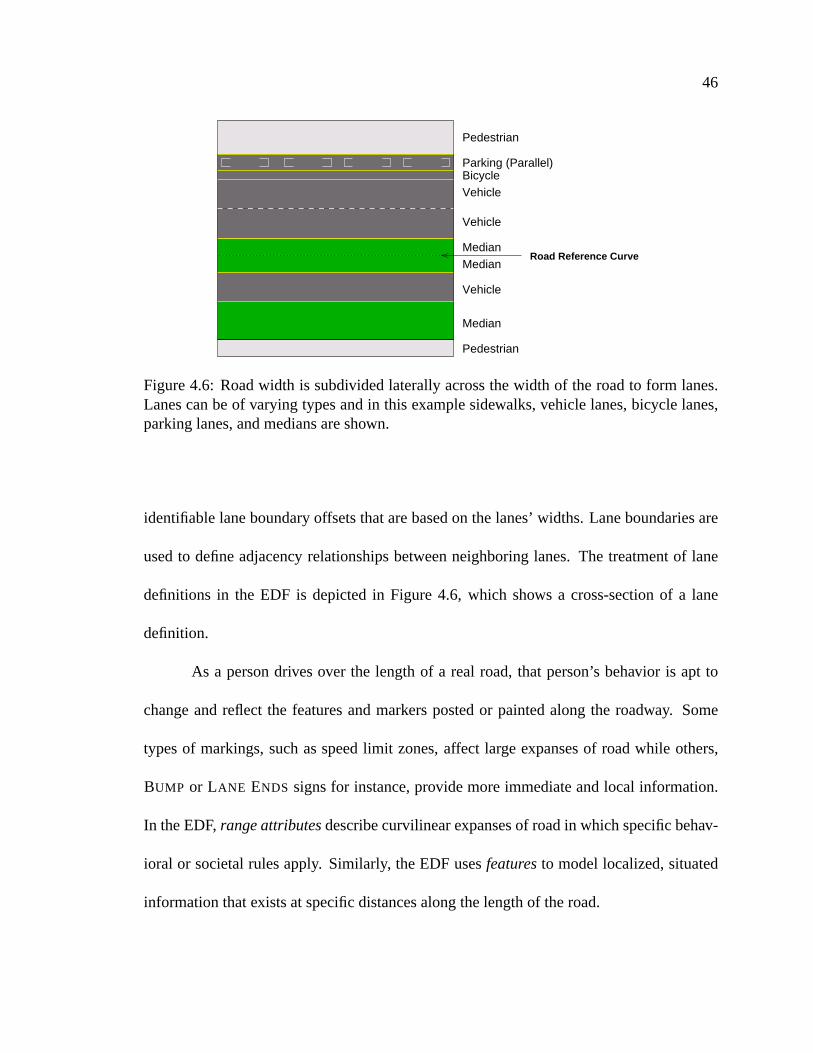
Figure4.6: Roadwidth is subdividedlaterallyacrossthewidth of the roadto form lanes.Lanescanbeof varyingtypesandin this examplesidewalks,vehiclelanes,bicycle lanes,parkinglanes,andmediansareshown.
identifiablelaneboundaryoffsetsthatarebasedon thelanes’widths. Laneboundariesare
usedto defineadjacency relationshipsbetweenneighboringlanes. The treatmentof lane
definitionsin the EDF is depictedin Figure 4.6, which shows a cross-sectionof a lane
definition.
As a persondrivesover the lengthof a real road,that person’s behavior is apt to
changeandreflect the featuresandmarkerspostedor paintedalongthe roadway. Some
typesof markings,suchasspeedlimit zones,affect large expansesof roadwhile others,
BUMP or LANE ENDS signsfor instance,provide moreimmediateandlocal information.
In theEDF, rangeattributesdescribecurvilinearexpansesof roadin whichspecificbehav-
ioral or societalrulesapply. Similarly, theEDF usesfeaturesto modellocalized,situated
informationthatexistsat specificdistancesalongthelengthof theroad.

47
(δ,ο1)
(δ,ο2)
Figure4.7: Curvilineardistanceis calculatedalongthereferencecurve (shown in black).Both coordinateshave the samedistanceparameter(
�), but different offsets ( �6� , ��� ).
Dashed,greenarcsrepresentthetruearc-lengthof thecurveat thedifferentoffsets.
During a simulation,the EDF maintainsinformationaboutthe simulationobjects
locatedon eachroad’s surfaceat any instanceof time. This informationcanbe queried
providing behaviors with importantroadoccupancy detail. Object locationon roads,as
well ashow thoseobjects’locationsrelateto eachother, facilitatesfollowing andobstacle
avoidancebehaviors. A completediscussionof roadoccupancy is providedin Section4.5.
4.3.1 Interpretationof CurvilinearCoordinates
Distancealongthe lengthof a roadin the EDF is treatedsimilar to mile-markers
alongan interstatein therealworld. A mile-marker marksaninvisible perpendicularline
thatcutsacrossall lanesof ahighwayto denotethelocationof aparticularmile,or distance
from the beginningof the roadway. Any vehiclescrossingthat line, no matterwhat lane
they arein, areconsideredto belocatedat thatmile marker.
By our definition, curvilineardistance(�) is measuredalongthe referencecurve;
curvilinearoffset ( � ) is calculatedasthe shortestperpendiculardistanceto the reference
curve at thatdistance.This interpretationof a curvilinearcoordinateusesa singlelongitu-

48
dinal representationof distance,asopposedto an offsetbaseddefinitionof distanceover
the curve. Thus, two positions � ��� �6�2� and � ��� ���H� definea line perpendicularto the road
referencecurve at milemarker�. Figure4.7 illustratesthehow theEDF treatscurvilinear
coordinatesin termsof mile markers.
Theadvantageof usingthis interpretationfor thecurvilinearcoordinateis that im-
portantspatialrelationshipsamongobjectsaredirectly determined.For instance,givena
setof of distanceparameterson a curvilinearsurface,we candefineanorderingof those
distancesover lengthof the surface. Similarly, usinga setof offset parameters,we can
determineanorderingthat runslaterallyacrossthesurfacedefinition. Using thesepartial
orderings,autonomousbehaviors canqueryneighboringobjectsandcomparecurvilinear
distancecoordinatesto understandlocal spatialrelationships.
4.3.2 Lanes
Lanespartition the roadsurfaceinto parallel, longitudinal regions. A roadin the
EDFbundlesasetof lanestogether. Roadscanbecomposedof oneor morelanes,with the
lanesetbeingorderedanddense–meaningthat thereareno gapsbetweenadjacentlanes.
Lanewidthsareconstantover thelengthof theroad.As a consequence,theroadprofile is
constantover thelengthof theroadasdeterminedby theextentsof thelaneoffsets.
In the EDF, a road’s lanesrun parallel to the road’s curvilinearaxis andmay not
straddlethat axis. Thus, the roadaxis is alwaysusedasa boundarybetweentwo lanes.
This restrictionis beneficialbecauseit allows for a discreteandsimpleorderingof lanes.
Consequently, a curvilinearoffsetcanquickly bemappedto a particularlaneby utilizing

49
Lane Type DescriptionVEHICLE General-purposevehiclesBICYCLE BicyclistsSIDEWALK PedestriansBUS BusesTRAIN Train tracksTRAM Trolley carsAGRICULTURAL Tractors,combines,threshers,wagonsCENTER-TURN Specializedturn laneMEDIAN LanespacingPARKWAY AreabetweenroadpavementandsidewalkANGLED PARKING AngledparkinglanesPERPENDICULAR PARKING PerpendicularparkinglanesPARALLEL PARKING Parallelparkinglanes
Table4.2: Varioustypesof lanesdefinedin theEDF.
thelanewidth andadjacency information.
Lanesin theEDF aretyped.For instance,a sidewalk is a typeof lanededicatedto
pedestrianswhile a center-turn laneallows traffic to make left turnson busystreetswith-
out blocking traffic flow. We choseto associatesidewalkswith roadsbecausesidewalks,
andothersimilar features,fit nicely with our definitionof lanes.Generally, sidewalksac-
company roadsin the real world, runningparallel to the roadfor the lengthof the road.
Table4.2 lists andbriefly annotatesthe lanetypesin EDF. In additionto behavioral type
information,lanesdesignateapreferreddirectionof flow, orientedwith respectto theroad
coordinatesystem.Somelanesallow bidirectionalmovement,soflow directionin a lane
maytakeononeof threevalues:Positive , Negative , or Both . Eachlanecanspecify
a surface-heightoffset valuewhich is usedto raise,or lower, the lane’s elevationrelative

50
to theheightof theits road.This attributeis usefulfor medians,parkways,andsidewalks
whicharesometimesraisedabove theheightof theroadto which they areadjacent.
4.3.3 RangeAttributes
In thereal-world, signsandmarkingsarepostedalongsideandonroadsto highlight
importantinformationrelatedto driving. For instance,speedlimits signsindicatethemax-
imum speedallowedon a sectionof road.Laneslinesaredrawn betweenlanesto prohibit
or allow certaintypesof behavior, suchaspassingin apassingzone.
The EDF modelszone-based,roadcharacteristicsas range attributes. Rangeat-
tributesare boundedcurvilinear regions that supply behaviorally important information
aboutthat region of the roadsurface. Rangeattributesarecharacterizedby a rectangular
curvilinearareaanddata. A rangeattribute’s areais definedby a pair of curvilinearco-
ordinatesE � �,KLK�� � KLK � � � �,M�N�� � M�N �,J specifyingthelower left � �,KLK�� � KLK � andupperright � �,M�N�� � M�N �
coordinateof roadsurface.The rangeattribute’s datais representedby anattribute label,
followedby a list of dataelements
�POH�Q� +6RTSQ( � ) U O S�)VU �HW OH��OV �HW OV��OX� �HG�GHGI�HW OH��O3�Y ��2�
In the caseof a speedlimitrangeattribute, the label is speedlimitandthe dataassociated
with it wouldbethespeedlimit over thatregion,asin
�PZ F )V) W U[R�\]R � ��^Y_ \ Fa` �
During the courseof a simulation,rangeattributescanbe dynamicallycontrolled
by an autonomousbehavior. Considerthe following, a railroadcrossinggatecanbe rep-

51
resentedasa dynamicallymanipulatedrangeattribute. In this example,a region of the
roadis markedto denotetheareaof the roadwherethe train trackscross.Theboundsof
this region demarcatethe locationof thegatesthatguardaccessto thecrossingarea.The
crossinggateattributedatais specifiedby
� +6+cbQ+ ��Z3Z R D8d �H� � �He �6Z R � R�fg)VhiU �5jlkmOH� ) � ( F �H� � �Hn ) dgOH� R�fg)VhmU ��jokiOH� ) � ( F �The curvilinear distances(
� � �H� � ) given in the rangeattribute datacomponentdetermine
the locationof therespective gatesalongtheroadsurface.Thetwo gates,labeledasPos-
itiveFlowGateandNegativeFlowGateto signify the relative directionof traffic flow they
towardwhichthey face,guardaccessto therailroadtrackcrossingregion. Thelogicalstate
of thesegatesis eitherUp or Downto representthephysicalstateof thegate.By attaching
an autonomousbehavior to this rangeattribute,we provide a mechanismto dynamically
monitor the crossingtrain tracksfor an oncomingtrain andsetthe stateof the rangeat-
tributegatesappropriatelyif a train is detected.Autonomousbehaviors, suchasvehicles,
navigating the roadwill querythe rrcrossingrangeattribute andcanreactto the logical
stateof thegate,eitherstoppingprior to thegates,or driving over theroadnormally.
4.3.4 Features
Whendriving on real roads,signspostedalongtheroadway will, at times,denote
immediateandlocal informationspecificto thatplaceon theroad.For instance,a SPEED
BUMP signoftenmarksthelocationof aspeedbumpontheroad’ssurface.In theEDF, road
signs,suchasthese,thatmarka perpendicularreferenceon a roadsurfacearerepresented
asfeatures.

52
A featureis a logical EDF componentthat modelslocalized,cross-sectionalin-
formation on the road’s surface. Featureshave a facing direction and can be laterally
boundedby two offsetsbracketing wherethe featureresideson the road. Featuresdif-
fer from rangeattributesin thatthey donotcoveranareaontheroad;rather, featurescover
a cross-sectionalslice of the roadsurface. A feature’s placementon the road’s surfaceis
determinedby a distance�, two offsetsboundingthe left andright offsetsthat thefeature
affects( � K ��p�� � � Nrqts�u � ), anda facingparameter, v .
featurelocation$ � ��� � K ��p�� � � Nrq[s�u � � vw�
Featurefacing direction determinesthe direction toward which the featurepoints. For
instance,on real two-way streets,signsfor theoncominglanesfacetowardtheoncoming
traffic anddo not affect the oppositeflow traffic lanes. Featuresthat are POSITIVE are
directedtowardtraffic travelingtowardtheendof theroad’scurvilinearcoordinatesystem;
NEGATIVE facingfeaturesaredirectedtowardtraffic moving towardtheorigin of theroad’s
curvilinearcoordinatesystem.Featurescanfacebothdirections.
The datacomponentof a featureis representedby a featurelabel followed by a
seriesof dataelements.
featuredata$ ��x ) OV� (a+c) U O S�)VU �HW OH��O3 �HW OH��OX� �HGHG�GI�HW OH��O��� ��,�
Like rangeattributes,featuredatamay be dynamicallycontrolledby an autonomousbe-
havior over thecourseof asimulation.
TheEDF suppliesqueriesfor interrogatingrangeattributesandfeatureson roads.
Rangeattributesoccurover curvilinearregionsof the road,andthus,queriesthatarepa-
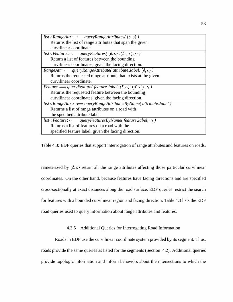
53
list y RangeAttrz "%$queryRangeAttributes( � ��� ��� )
Returnsthelist of rangeattributesthatspanthegivencurvilinearcoordinate.
list y Featurez "%$queryFeatures( � ��� ��� � � ��{|� � { � � v )
Returna list of featuresbetweentheboundingcurvilinearcoordinates,giventhefacingdirection.
RangeAttr">$
queryRangeAttribute(attribute label, � ��� �3� )Returnstherequestedrangeattributethatexistsat thegivencurvilinearcoordinate.
Feature"%$
queryFeature( feature label, � ��� ��� � � ��{|� � { � � v )Returnstherequestedfeaturebetweentheboundingcurvilinearcoordinates,giventhefacingdirection.
list y RangeAttrz "%$queryRangeAttributesByName(attribute label )
Returnsa list of rangeattributesona roadwiththespecifiedattributelabel.
list y Featurez "%$queryFeaturesByName(feature label, v )
Returnsa list of featureson a roadwith thespecifiedfeaturelabel,giventhefacingdirection.
Table4.3: EDFqueriesthatsupportinterrogationof rangeattributesandfeaturesonroads.
rameterizedby � ��� �3� returnall the rangeattributesaffecting thoseparticularcurvilinear
coordinates.On theotherhand,becausefeatureshave facingdirectionsandarespecified
cross-sectionallyat exactdistancesalongtheroadsurface,EDF queriesrestrictthesearch
for featureswith aboundedcurvilinearregionandfacingdirection.Table4.3lists theEDF
roadqueriesusedto queryinformationaboutrangeattributesandfeatures.
4.3.5 AdditionalQueriesfor InterrogatingRoadInformation
Roadsin EDFusethecurvilinearcoordinatesystemprovidedby its segment.Thus,
roadsprovidethesamequeriesaslistedfor thesegments(Section4.2).Additionalqueries
provide topologic informationandinform behaviors aboutthe intersectionsto which the

54
int"%$
numberOfLanes()Returnsthenumberof laneson theroad.
list y Lanez ">$laneProfile()
Returnsthesetof lanesthatmakeup thelaneprofileon theroad.Lane
"%$laneToLeft(lane reference)
Returnsthelaneto theleft (if it exists)of thelaneparameter.Lane
"%$laneToRight(lane reference)
Returnsthelaneto theright (if it exists)of thelaneparameter.Intersection
"%$startIntersection()
Returnsa referenceto theroad’sstartingintersection.Intersection
"%$endIntersection()
Returnsa referenceto theroad’sendingintersection.Intersection
"%$nextIntersection(flow direction)
Givenadirectionof flow on theroad,returntheforwardfacing(asdeterminedby flow direction)intersection.
float">$
distanceToIntersection(�, [ start } end])
Givenacurvilinearcoordinatedistanceparameterandanintersectionlabel,returnthedistanceto theintersection.
float">$
distanceToNextIntersection(�
, flow direction)Givenacurvilinearcoordinatedistanceparameterandaflow direction,returnthedistanceto theforwardfacingintersection.
Table4.4: Additionalqueriessupportedby roadsin theEDF.

55
roadconnects.Relative queriessupportqueriesbasedon thebehavior’s immediatedirec-
tion of flow with respectto theroad’scurvilinearcoordinatesystem.
4.4 Intersections
In therealworld, intersectionsserveasinterchangesbetweendifferentroads.Driv-
ing behavior is different in intersectionsthanon roads. Roadsaresimply organizedinto
parallelstreamsin which humanbehavior canbe tightly regimented,andreasonablypre-
dictable.Intersections,ontheotherhand,arelogically complicated,messy, and,in thefield
of driving simulation,notoriouslydifficult to model.Thechannel-likepassagesconnecting
incoming to outgoinglanescriss-crossandoverlapeachother. Spatialrelationshipsbe-
cometangled,highly complex, anddifficult to identify. In real intersections,societalrules
andconventionsdeterminewhohasright of wayandhow traffic shouldproceed.
In theEDF, intersectionsspecifyinput/outputrelationshipsbetweenthelanesof the
roadsconnectedto the intersection.EDF intersectionsdefinea standardinterconnection
schemethatdetailshow lanesinterlink andinterrelatein the intersection.Intersectionsin
the EDF have four parts: (1) an exterior polygonalboundaryto which roadsincident to
theintersectionconnect,(2) setsof individual, lane-likecorridorsthatroutetraffic through
the intersection,(3) lists of dependenciesbetweencorridorsthatdescribehow objectson
different corridorsrelate,and (4) traffic control devices that regulateentranceinto and
movementthroughtheintersection.
56
4.4.1 IntersectionBoundaries- ExteriorGeometry
Intersectionsin theEDF areboundedby a convex polygon.Theedgesof thepoly-
gonareusedaslandmarksto which theterminatingedgesof connectingroadscanadjoin,
formingsmoothtransitionsbetweenroadandintersectiongeometry.
As with roads,simulationobjectscanoccupy intersections.Theconvex geometric
descriptionof theintersectionpolygonallows theEDF to performefficient objectin poly-
goncomputationsduringasimulation.Intersectionoccupancy semanticswill bediscussed
in Section4.5.
4.4.2 Corridors
In real intersections,the connectionsbetweenlanesare often implicitly defined.
At times however, especiallyin the presenceof adjacentturning lanes,or when it isn’t
visually obvious, laneslines arepaintedin the intersectionto explicitly guidedriverson
how they shoulddrive throughtheintersection.In theEDF, theconnectionsbetweenlanes
areexplicitly representedanddescribetheroutesbetweenincomingandoutgoinglanesof
roadsthatconnectto theintersection.Theseroutesarecalledcorridors.
Corridorsareanalogousto single-laneroads.They containa segment,which may
be hierarchical,that describesa curvilinear path betweenthe two lanesincident on the
intersection.The corridor’s referencecurve connectsthe terminationpointsof two lane
centerlineson the intersectionboundary. Thus, the corridor’s referencecurve is a lane-
centerlineto lane-centerlineroute.Corridorwidth is determinedto bethemaximumof the
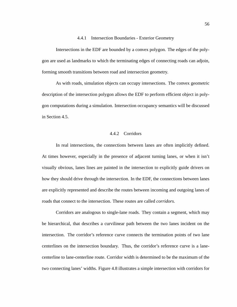
two connectinglanes’widths.Figure4.8illustratesasimpleintersectionwith corridorsfor
57
Figure4.8: Corridorscrossintersectionsandconnectincoming lanesto outgoinglanes.Thecorridorsleaving theleft andright roadsareshown in red.
the left andright roadsdrawn in dashedlines. Corridorscanrepresentany routethrough
theintersection.Thefigureshowscommonlyusedroutesfor driving straight,turningright,
andturningleft.
Corridorsaretyped.Corridortypeinformationservesthesamepurposeaslanetype
doesfor EDF roads.Both provide contextual informationto behaviors. The EDF places
no restrictionson which corridor typescanmatchup with which lanetypes. This means
that logically incompatibleconnectionscanbe constructedandit is up to the modelerto
correctly matchcompatibletypes. For instance,a bike lane can reasonablyconnectto
a vehicle lane,but connectinga vehicle lane to a median,sidewalk, or tram lane is not
sensible.In theformer, boththebike laneandvehiclelanessupportdrivablevehiclesthat
maneuver on paved surfaces.In the latter, it is not clearhow a vehiclewould drive on a
tramtrack,let aloneasidewalk, or median.

58
4.4.2.1 CorridorAttributes- Flow, Stoplines,andCurbs
At the intersectionboundary, incominglanesconnectto corridorsleadingto lanes
on outgoingroads. Whenmorethanonecorridor branchesout from the sameincoming
lane,multiple pathwaysexist throughthe intersectionfrom that lane. Behaviorally, these
juncturesarenoteworthy becausethey forcebehaviors to make decisionsasto which cor-
ridor to use.Oftentimes,randomdecisionswill suffice.
Unfortunatelythough,randomdecisionsproducerandombehavior thatmaynotbe
consistentwith thedesignof theenvironment.Fromthestandpointof thedatabasemodeler,
thesejuncturespresentanopportuneplaceto encodemodelingintentionsanddesignnotes
thatreflectthemodeler’sexpectationsabouttraffic movementon thelanesandcorridorsof
theenvironment.
Similarly, traffic modelingalgorithmscanusecorridorbranchesto encodedesired
traffic flow statisticsthatwill influenceturndecisionsof autonomousvehicles.Algorithms
for managingambienttraffic andmaintainingvarioustraffic modelsattemptto controltraf-
fic densityandflow onroadwaysby influencingtheroutingdecisionsof traffic in intersec-
tions[2, 12,11].
TheEDFencodesaflowpercentageattributein eachcorridorindicatingthedesired
percentageof traffic enteringtheintersectionon that lanethatshouldtake thegivencorri-
dor. Theaccumulatedpercentagesfor all corridorsleaving a lanemustsumto one. EDF
enforcesthis constraintby acceptingflow percentagesbetween~ and � andthennormaliz-
ing thesetof flow percentagesto beconsistentover therange[ ~ , � ]. For corridorsthatare

59
bidirectional,flow percentagesarespecifiedat bothendsof thecorridor.
By encodingflow percentageinto thecorridor, autonomousbehaviors, suchasve-
hiclesor pedestrians,canmake educated,yet randomdecisionsthat are consistentwith
desiredtraffic distributions. Moreover, databaseand traffic modelerscanprescribeflow
percentagesthat matchthe designof the road, or scenariobeing developedwithout re-
codingthevehiclesthatdrive in theenvironment.
Flow percentagescan be dynamicto evolve to changesin simulationstate. For
instance,autonomoustraffic managerbehaviors canmodify andtweakthe flow percent-
agesat intersectionsduringasimulationto routetraffic accordingto timevaryingscenario
requirementsandtraffic distribution rulesandgoals.
On roadsin the United States,mostcontrolledintersectionsaremarked with sto-
plinesto designateastoppinglocationfor vehicles.TheEDFencodesstoplinedistancefor
eachcorridor that is usedto enterthe intersection.This is primarily usefulif theintersec-
tion boundaryencompassesthecrosswalk andstoplinemarkings.Otherwise,stoplinecan
beencodedasa featurealongtheroadway. Stoplinedistanceis a distancemeasuredalong
thecurvilinearreferencecurve of thecorridorandcanbequeriedby behaviors approach-
ing the intersectionto ensurethat theobjectbeingcontrolledby thebehavior stopsat the
appropriateplacealongthe corridor. In situationswheremultiple corridorsbranchfrom
a singleincominglane,it maybethecasethatstoplinedistancewill bedifferentfor each
corridor.
Stoplinesare primarily for vehiclesand mark an important location on the road
60
surface.For pedestrians,curbsactlikea stoplines,guardingentranceinto theroads.More
importantly, curbsoftensignify abruptchangeof elevation. In theEDF, it is importantthat
pedestrianbehaviorshaveaccessto thelocationof thecurbsothatfoot fallscanaccurately,
and realistically be placedon the curb [65]. The EDF modelsthe location of curbsby
specifyinga curb distanceattributeon pedestriancorridors.Curbdistanceis encodedinto
the corridor as the distancefrom either the beginning, or the end, of the corridor. As
with stoplinedistance,curbdistanceon bidirectionalcorridorsis specifiedat bothends,if
required.
Flow percentage,stoplinedistance,andcurbdistancearespecializedattributesbuilt
into thecorridordescription.In additionto thesespecialized,built-in attributes,corridors,
likeroads(seeSection4.3),canspecifyrangeattributes,and/orfeaturesalongthecurvilin-
earcoordinatesystemusedto definethecorridor.
4.4.2.2 Junctures
Theintersectionboundaryuniquelydefinesthegeometryof theintersection.Roads
abut to theedgesof theintersectionmakingthetransitionfrom roadto intersectionsmooth
andseamless.Similarly, internalcorridorsseamlesslyalignwith theintersectionboundary.
Laneson connectingroadsmapto specificcorridorsin the intersection.In general,there
are many attributesand elementsthat needto be specified;intersectionsare difficult to
model.
Luckily, in realurbanenvironmentsmultiple intersectionsoftenhave thesamerel-
ativestructureandcharacteristics,with only minordifferencesbetweenintersectionsbeing

61
thewidthsof theroadsthatconnectto theintersections.Downtown city blockintersections
areanexcellentcasein point. In thesyntheticenvironment,reuseof structureis evenmore
widely usedandthereforeapparentin themodels.
Intersectionsaredifficult to specifyandmodel. In theEDF, we leveragemodeling
effort by affording intersectionreuse. It makes senseto reusethe structure,logic, and
relationalcharacteristicsdefinedin the intersection,especiallywhenthe only differences
betweenintersectionsmaybetheincominglanewidths.
TheEDFfacilitatesintersectionreuseby definingconnectionsitescalledjunctures.
Juncturesareplacedalongthe edgesof the intersectionboundaryandmark locationsto
which roads,lanecenterlines,andcorridorscanconnect.By pre-definingtheseconnection
points, intersectionscanbe constructedindependentof their connectionsto roads. As a
consequence,corridorscanbespecifiedwithout regardto which roadsor lanesthey con-
nect. In this sense,intersectiondefinitionsbecomestemplatesthat canbe instantiatedas
neededin the environmentdescription. Upon instantiationin the EDF, the bindingsbe-
tweentheconnectingroads,lanes,andcorridorsbecomeeffective andexplicit, cementing
theintersectionat thatlocation.
Two typesof juncturesareusedin theEDF:fixedandfloating. Fixedjuncturesmark
anexact locationon theintersectionboundaryedge.They areusefulfor connectingroads
and well-definedcorridorsto the intersection. Floating juncturesdescribea connection
point on theintersectionboundarythat is not yet boundto a specificlocationon theedge.
Floatingjuncturesareusedwhenwe know a connectionwill bemade,but we don’t know
62
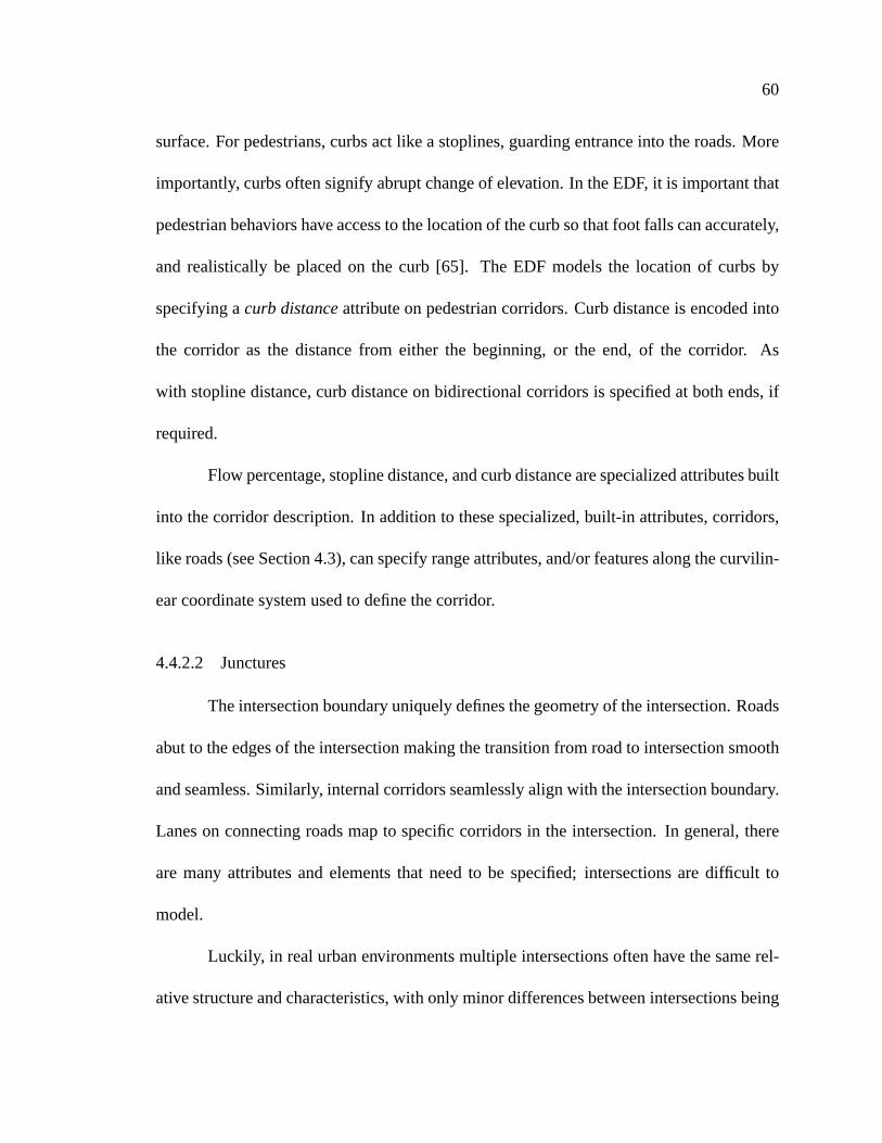
Figure4.9: Illustrationof fixedandfloatingjuncturesplacedalongtheintersectionbound-ary. Redsquaresdenotefixedjunctureswhile greendotsrepresentfloatingjunctures.Thecorridorsbetweenthejuncturesareshown aswell.
at what point on the boundaryedgethe connectionwill exist. Floatingjuncturesarethe
primary tools for makingintersectionsreusable.Internally, corridorscanbeconnectedto
bothfixedandfloatingjunctures.
Multiple juncturescanbeplacedonanedgeto accommodatemultipleconnections.
Whenmorethanonejunctureis placedalonganedge,theorderingof juncturesis always
preservedby theEDF. Figure4.9 illustratesa simpleintersectionwith bothtypesof junc-
tures. The red squaresrepresentfixed junctures,while the greendots representfloating
junctures.
Junctureorderingalongan edgeis invariant. When initially defined,fixed junc-
turesremainfixed alongthe edgewhile floating juncturesarespreadout evenly between
neighboringabsolutejuncturesandedgevertices.

63
l�ane 3
lane 1
lane 2
l�ane 4
l�ane 3
lane 1
lane 2
l�ane 4
l�ane 3
lane 1
lane 2
l�ane 4
Figure4.10: Theroadaxisconnectsto thefixedjuncture(shown asa redsquare)andthefloating junctures(shown asgreencircles)adaptto fit the offsetsof the matchinglanes.This three-partillustrationshowstheprocessof connectinga roadto anintersection.
Whenwe connecta roadto anintersection,we attachtheroad’s referenceaxisto a
fixedjunctureontheintersectionboundary. Only theterminatingcoordinatesof roadsmay
connectto a juncture.However, morethanoneroadmayconnectto anedgeaslong asit
connectsto aseparatefixedjuncture.
Oncea roadis connectedto an intersection,the EDF attemptsto align theneigh-
boringfloating junctureswith the road’s lanes’centerlines.Floatingjuncturesconnectto
theending,or beginning,coordinatesof lanecenterlines.Floatingjuncturestranslatealong
theboundaryedgeto accommodatefor thefixedspacingof thelaneson theroads.A float-
ing juncturepushes,or pulls, neighboringfloatingjuncturesasit translatesalongtheedge
to accommodatethe width of theconnectinglane. Junctureorderingis alwayspreserved
alongan edge.Figure4.10 illustratesthe processof connectinga roadto an intersection
andhow thejuncturesadaptto fit theroad’s lanes.
To assistmodelingeffort, theEDFcangeneratecubicsplinesegmentsto modelthe
corridorgeometrybetweenjuncturesautomatically. Theseautomaticallydefinedsegments

64
are beneficialwhenusingfloating junctures. They allow the EDF to adaptthe corridor
definitionto thelocationsof thefloatingjuncturesonceroadsandintersectionsconnect.
On the other hand,corridor segmentscan be definedexplicitly, but in thesesit-
uations,the EDF cannotadaptthe corridor segmentto fit updatedlocationsof floating
junctureendpoints.It is suggestedthat in thesecircumstances,fixed juncturesbeusedto
ensurerigid corridorplacement.
In termsof databasemodeling, juncturesallow intersectionsto be modularand
reusable.A databasemodelercanreusean intersectiondescriptionby delayingthebind-
ing, or connection,betweenroad and junctureuntil a later time. When designingand
developinga databasemodel,a singleintersectioncanbeinstantiatedasneeded,connect-
ing roadsandlanesto theappropriatejunctureson the intersectionedge.In essence,this
producesintersectiondescriptionsthatareparameterizedby thesetof roadsthat connect
to theintersection.
4.4.3 Dependencies- InternalIntersectionConstraints
As corridorspassthroughintersectionsthey interweavein complex ways:crossing,
overlapping,merging, or splaying. Many corridorsfeedinto the sameoutgoinglaneand
singleincominglanesdivergeinto many corridorsconnectedto differentoutgoinglanes.In
real intersections,traffic controldevicesandright of way conventionsgoverninteractions
of vehiclesondifferentcorridors.Without these,chaoswouldensue.
As driversenterandnegotiatetravel throughintersections,they needto attendto
many differingconcernsandconstraints.For instance,turningleft is precededby locating

65
DependenciesADJACENT TO
CROSSES
CROSSWALK
DIVERGES WITH
MERGES WITH
RIGHT ON RED
RIGHT OF WAY
Table4.5: Typesof dependenciesthatcanbeusedin theEDF to describethe inter-objectrelationshipson corridors.
a safegapin oncomingtraffic. Evendriving straightthroughan intersectionrequiresthat
thedriverpaysomeattentionto thetraffic on crossingcorridors.
The constraintsthat are implicitly definedbetweenthe objectstraveling through
intersectionsarecorridor dependent.The EDF encapsulatesinter-objectconstraintsinto
corridor dependencyinformation. Dependenciesdefinepotentiallyhazardousandimpor-
tant interrelationsamongtraffic on differentcorridors. The EDF encodesdependencies
into the intersectionon a per-corridor basis. Simply put, dependenciessupplybehaviors
with context dependentinformationrelatedto thecorridoronwhichthey arenavigating.A
dependency mapsa dependency labelto oneor morecorridors,asin
� W ) F ) D W ) D b�- U O S�)VU � b � +�+�R W � + � b � +�+6R W � + � �HGHGHG�� b � +6+�R W � + �Y ����Multiple dependenciescanbespecifiedfor eachcorridorin anintersectionandareencoded
into the environmentby the databasemodelerdependinguponthe capabilitiesof the au-
tonomousbehaviors. The EDF doesnot specifya presetlist of dependenciesfor useby
behaviors. To provide a feel for different typesof dependencies,Table4.5 lists a setof

66
C0
C1
C2
Figure4.11: An illustration of the useof dependenciesto negotiatea left turn. Vehiclestravelingoncorridor ��� and ��� mayposethreatsto objectstravelingoncorridor �� .
commondependencies.
Dependenciescompartmentalizebehavioral activities. Eachdependency in the in-
tersectionsignifiesa relationshipbetweentheobjectson two corridors. Autonomousbe-
haviors canbedesignedandorganizedaroundtheserelationships,sothatasdependencies
are encountered,separate,behavioral-dependency units can be deployed to react to the
dependency on anas-neededbasis.
For example,assumeanautonomousvehicleneedsto make a left turn at an inter-
section,asdepictedin Figure4.11. The darker vehiclewill enterthe intersectionon the
corridor labeled �� . In this circumstance,the vehicle’s turning behavior must accepta
safegapin theoncomingtraffic. Theoncomingtraffic corridorsdenotedby ��� and ��� are
67
specifiedin thedependency list of corridor �� as
� mergeswith� ���2�
� crosses� ���H�
Thedarker vehicle’s behavior canusethedependency list to dynamicallycreatetwo turn-
ing dependentsub-behaviors: one for dealingwith the merging traffic, and anotherfor
acceptinga safegapin theoncomingtraffic. After theturn is completed,thesetwo newly
instancedbehaviorscanberetireduntil lateruse.
4.4.4 Traffic Control
Behavior in EDFintersectionsis regulatedby traffic controldevices(e.g. stopsigns,
traffic lights,pedestrianwalk signals)thatcontroltraffic flow onaper-corridorbasis.Bidi-
rectionalcorridors,suchassidewalks,arecontrolledunilaterallyby a singletraffic control
state. Autonomousvehicles,for instance,can interrogatethe intersectionfor the traffic
controlstateassociatedwith thecorridor thevehicleplansto useto travel throughthe in-
tersection.
Traffic control statemay be static or may be determineddynamicallyby an au-
tonomousbehavior. For example,in the EDF, a single traffic light behavior cancontrol
the stateof a particularintersection’s traffic light. The stateof the traffic lights at other
intersectionsareusuallycontrolledby separatebehaviors. However, at times,all thetraffic
lights at a seriesof intersectionsmaybesynchronizedwith eachotherto maximizetraffic
flow throughtheroadnetworks.
Traffic controlstatecanbedeterminedby multiplebehaviors. In uncontrolledinter-

68
Traffic Control StatesRED
YELLOW
GREEN
FLASHING RED
FLASHING YELLOW
STOP SIGN
THROUGH
UNCONTROLLED
Table4.6: Traffic controlstate.
sections,no traffic controldevice is required.Table4.6 lists thetraffic controlstatesused
in theEDF to regulatebehavior at intersections.
4.4.5 ZeroLengthIntersections
Polygonalintersectionsspecify a fixed geometrywith corridorsmappingroutes
betweenincomingandoutgoinglanes.However, at times,it makessenseto simplyconnect
theendsof two roadstogetherwithout thebehavioral, andmodeling,overheadassociated
with acompleteintersection.
In essence,the intersectionstructureis collapsedto a single edge–adegenerate
polygon. In the EDF, theseintersectionsare called zero-lengthintersectionssincethey
occupy nospaceyet actlike regular, polygonal-basedintersections.
Zero-lengthintersectionsusezero-lengthcorridorsto describelane-to-laneconnec-
tions andspecifydependency informationbetweencorridors. Zero-lengthcorridorshave
no length,andarepoint-basedconnectionsthatprovideamappingbetweenlanesconnect-

69
Lane Addition
Lane End
Figure4.12: Exampleof how a zero-lengthintersectionconnectstwo roadswith differinglanedefinitions.
ing to thejunctureson thezero-lengthintersection’sedge.
Traffic control at zero-lengthintersectionsworks identically to traffic control in
regularEDF-basedintersections.However, zero-lengthintersectionsareusedto describe
seamlesschangesin roadstructurewhere,for themostpart,no traffic control stateis re-
quiredandtraffic candrive throughwithout changeof behavior.
Therearetwo instanceswherezero-lengthintersectionareused:(1) forming road
loops,and(2) laneterminationor laneaddition.Figure4.12depictsaninstanceof usinga
zero-lengthintersectionto connecttwo roadswith differing lanedefinitions. Whenusing
zero-lengthintersections,lanecenterlinesmustalign on the connectingroadssincethere
arenocorridorsto mergebetweenlanesof differentoffsets.
4.4.6 HierarchicalIntersections- InternalRouting
TheEDF intersectionmodeluseshierarchicalintersectiondescriptionsto provide
thenecessarystructurefor describingcomplex internalintersectionrouting.To understand

70
Bicycle LanesCar LanesPedestrian Lanes
Figure4.13: Exampleof a hierarchicalintersectiondefinition. Note the internalintersec-tionsforming thepedestriansidewalk intersections.
internalrouting,considerthemannerin which sidewalks intersect.Sidewalk lanesin the
EDF connectto sidewalk corridors. Thesecorridorscriss-crossforming their own inter-
sections.Oftentimes,thelocationof thesepedestrianintersectionsis within theboundsof
the intersectiongeometry. Within internalintersections,corridorsconnectto corridorsat
junctureson theedgesof thechild intersection.Figure4.13 illustratesa three-way inter-
sectionwheresidewalkscometogetherwithin theboundaryof the larger intersection.At
thesecrossings,wedefineinternalintersections.
4.4.7 IntersectionandCorridorBehavior Queries
Table4.7 lists queriesprovided by the intersectionandcorridor structuresin the
EDF. Intersectionqueriesprovideaccessto corridorsconnectingroads,lanes,andcorridors

71
Intersection Querieslist y Corridor z "%$
queryCorridors(Road,Lane)Returnsa list of Corridorsthatconnectto theroadandlaneprovidedasparameters.
list y Corridor z "%$queryCorridors(Corridor, [ start } end] )
Returnsa list of Corridorsthatconnectto thespecifiedendof thecorridorprovidedasparameterif theintersectionis aninternalintersection.
TCState">$
queryTCState(Corridor )Returnsthetraffic controlstatevalueregulatingmovementalongthespecifiedcorridor.
boolean">$
isZeroLength()Returnsabooleanvalueindicatingif theintersectionis azerolengthintersection.
Corridor SpecificQuerieslist y Dependencyz ">$
queryDependencies()Returnsa list of dependencieson thecorridor.
boolean">$
connectsToRoad([ start } end] )Returnsabooleanvalueindicatingwhetherthespecifiedendof thecorridorconnectsto a road,or not. If false,thecorridorconnectsto aninternalintersection.
Intersection">$
startIntersection()Returnsa referenceto theintersectionat thebeginningof thecorridor.
Intersection">$
endIntersection()Returnsa referenceto theintersectionat theendof thecorridor.
Intersection">$
nextIntersection(flow direction)Givena relativedirectionof flow on thecorridorbasedon thecorridor’scurvilinearaxis,returntheforwardfacing(asdeterminedby flow direction)intersection.
float"%$
distanceToIntersection(�, [ start } end])
Givenacurvilinearcoordinatedistanceparameterandanintersectionlabel,returnthedistanceto theintersection.
float"%$
distanceToNextIntersection(�
, flow direction)Givenacurvilinearcoordinatedistanceparameterandaflow direction,returnthedistanceto theforwardfacingintersection.
Table4.7: Intersectionqueriesrelateconnectingroadsandcorridorsandprovide trafficcontrolstatefor corridors.Corridorqueriesprovideaccessto dependency informationandwhichintersections(in thecaseof internalintersections)connectto thecorridorterminationpoints.
72
togetherandalsogiveaccessto thetraffic controldevice stateat theintersection.Because
corridorsarecurvilinearstructures,they supportall thequeriesthatacurvilinearcoordinate
systemmustprovide,asdescribedin Section4.2. They alsosupportthefeatureandrange
attribute queriesdescribedin the roadsection(Section 4.3). In addition,EDF corridors
provideaccessto dependency andinternalintersectioninformation.
4.5 Occupancy
In additionto thestructureandlayoutof thestaticenvironment,it is essentialthat
dynamicobjectsbe aware of other dynamicobjects. For example,a vehicleon a road
mustavoid crashinginto thevehicleimmediatelyaheadof it in its lane.Pedestriansdodge
andweave aroundotherpedestrianson the sidewalk. To be ableto avoid collisionsand
to interactin other ways, autonomouscharactersneedaccessto the dynamicobjectsin
theenvironment(e.g. vehicles,pedestrians),but moreimportantly, they needaccessto the
spatiallocationsof theobjectsnearthemin theenvironment.
TheEDFmaintainsrelativeandspatiallocationsof objects.Relativelocationsrefer
to the relationshipsbetweenobjectsand the surfacesin the environmenton which they
exist. In otherwords, relative locationsdescribeoccupancyon a surface. For example,
relativelocationinformationcanprovideanswersto queries,suchaswhatvehiclesareona
particularlane,whatpedestriansarein acrosswalk, or whatobjectsarein anintersection.
Spatiallocationsimplydescribesthelocation,or position,of theobjectin theenvi-
ronment.This canbeexpressedin two ways. For one,spatiallocationcanbetheobject’s
Cartesiancoordinates.On theotherhand,if theobjectis locatedon a curvilinearsurface,

73
spatiallocationcanbeacurvilinearcoordinate,describedby��� � .
Occupancy is derived from the spatialpositionsof objectsandhow they relateto
thestructuresof thesimulatedenvironment.But first, we needanunderstandingof whatit
meansto occupy something.
4.5.1 Occupying Spacein theEDF
In the EDF, the term occupancymeanshow simulationobjectsoccupy spaceon
roads,intersections,andcorridors.For our purposes,occupancy is a by-productof anor-
thographicprojectionof theobjects’geometryontothegroundsurface,andhenceontothe
EDF structurescoveringtheground.It is quite importantthatbothanimateandinanimate
objectsbeincludedin occupancy computation.For instance,we expectpedestrianswalk-
ing onthesidewalk to dodgeandweavearoundeachotherto avoid collisions.Likewise,we
expectsimilarbehavior if therearelamppostsor parkingmetersplacedalongthesidewalk.
Theanswerto thequestionDoesa particular objectoccupya particular structure?
dependsuponwho asked the questionandwhy the questionwasasked. Somebehaviors
simply maynot requireasmuchdetail aboutoccupancy asothers.For instance,whether
or not a vehicle’s bumper is encroachinginto anothervehicle’s lane dependsupon the
attitudeof thedriver. A conservative behavior mayfind themovementof theneighboring
vehicle’sbumperoffensiveanddangerous,while aninattentivedrivermaynot evennotice
thebumper.
Nonetheless,it is important to establisha baselinefor occupancy. At the most
primitive level, eachobjectin thesimulationis representedby a singlepoint denotingthe

74
positionof it’ s centerof geometry(CoG).Thiscoordinatecanbeusedfor assigningpoint-
basedoccupancy.
4.5.2 A Witnessto Occupancy
Weformulatedescriptionsof occupancy in termsof witnesses. This is in contrastto
describingoccupancy in termsof thesimulationobjectsthemselves.Asanexample,wecan
describeoccupancy onaroadby listing all theobjectsonthatroad.Thewitnessdescription
is anoccupancy abstractionthatcantell uswhatobjectsoccupy acertainstructure,but can
also provide additionalinformation that describeshow an object occupiesa space. For
instance,a point-basedwitnessprovidesthemostprimitive form of occupancy in theEDF
by mappingan object’s CoG onto oneor moreEDF components2. This witnesswould
providea referenceto theoccupying objectaswell asthepointof occupancy.
EDF doesnot restrictoccupancy to beinga point-based,CoG computation.The
witnessmetaphoris anintuitiveabstractionfor expressingoccupancy andis advantageous
in that it allows for many differenttypesof occupancy representations.A witnessin the
EDFatteststo thetimeandplacementof aspecificobjectonaparticularroad,intersection,
or list of corridors. A witnessspecifiesa description(geometricor otherwise)regarding
how the objectoccupiedspaceon the EDF component.This includesa referenceto the
occupiedobject. For instance,our point-basedwitnessprovidesanautonomousbehavior
with the following information: (1) a referenceto the occupying simulationobject,(2) a
time-stampdatingthe occupancy, (3) the Cartesiancoordinate,andoneof the following:2Sinceroadsandintersectionsdonotallow for overlap,it is only in thepresenceof overlapping
corridorsthataCoGmaybeon morethanonecomponentata time.
75
RoadQuerieslist y Witnessz "%$
queryObjects()Returnsall point-basedwitnessesto road’s occupants
list y Witnessz "%$queryObjectsInLane(lane ref )
Returnsall point-basedwitnessesto occupantsonaparticularlaneWitness
"%$queryLeader(distance, ori )
Returnsawitnessrepresentingthenext objectin thedirectionspecifiedby ori afterdistanceon a road
Witness"%$
queryLeaderInLane(lane ref, distance, ori )Returnsawitnessto theleaderoccupantwithin a lane
list y Witnessz "%$queryAllLeadersInLane(lane ref, distance, ori )
Returnsa list of witnessto all theobjectsaheadof a particulardistanceIntersection Querieslist y Witnessz "%$
queryObjects()Returnsall point-basedwitnessesto intersectionoccupants
list y Witnessz "%$queryObjectsInCorridor(Corridor, width )
On demandquerythatcalculatestheoccupantswithin a specifiedwidth of thecorridoraxis
Witness"%$
queryLeaderInCorridor(Corridor, width,distance, ori )On demandquerythatcalculatestheleaderaheadof agivendistanceonacorridor
GeneralEDF OccupancyQuerieslist y Objectz "%$
queryAllObjects()Returnsall theobjectsin thesimulation
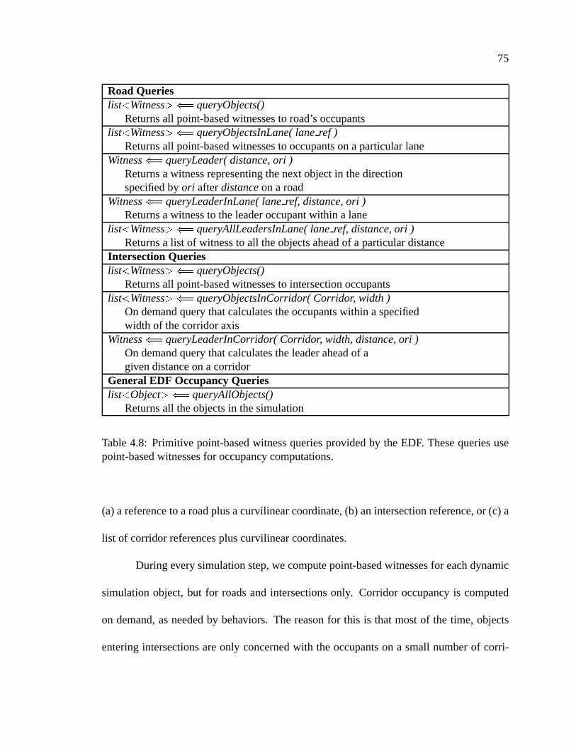
Table4.8: Primitive point-basedwitnessqueriesprovidedby theEDF. Thesequeriesusepoint-basedwitnessesfor occupancy computations.
(a)a referenceto aroadplusacurvilinearcoordinate,(b) anintersectionreference,or (c) a
list of corridorreferencespluscurvilinearcoordinates.
Duringeverysimulationstep,wecomputepoint-basedwitnessesfor eachdynamic
simulationobject,but for roadsandintersectionsonly. Corridor occupancy is computed
on demand,asneededby behaviors. The reasonfor this is thatmostof the time, objects
enteringintersectionsareonly concernedwith theoccupantson a small numberof corri-

76
dors. The intersectiondependency structuressupportthis style of corridor occupancy by
modularizingthe inter-objectrelationshipson the corridorsof the intersection;behaviors
needonly focuson theobjectson specificcorridors.Thus,givena particularcorridorand
intersection,the EDF cancomparethe CoG positionsof the objectsin the corridor with
the singlecorridor. Contrastthis computationwith the calculationsrequiredto compute
point-basedoccupancy on all corridorsin the intersection.In this situation,eachcorridor
is comparedwith eachobject. Thesecomputationsaremoreoften thannot, unnecessary
andwasteful. Therefore,we leave it to behavior programsto requestcorridoroccupancy
asneeded.Table4.8 lists the primitive point-basedqueriesprovided by the EDF. As an
example,we canqueryall theobjectson a roadby usingthefunctionqueryObjectswith a
roadreference.This functionwouldreturnbacka list of point-basedwitnesseswhoseCoG
mapontoaprojectionof theroadsurface.
4.5.3 SophisticatedWitnesses
The EDF leveragesthe definition of occupancy on to the witnessabstractionand
computation.Point-basedoccupancy works fine for somebehaviors, suchas lanebased
following, but it may not be sufficient for more complex parallel parking behaviors, or
laneencroachmentdetectionbehaviors. Moreover, thepoint-basedwitnessis imprecise;it
doesn’t tell thebehavior muchabouthowtheobjectis situatedat its position.
More intelligent, informed,andsophisticatedwitnessescanbebuilt to supplyde-
tailed information abouthow objectsoccupy structuresin the environment. Considera
line-basedwitnessthatrepresentsgeometryby oneor moreline segments,describinghow

77
eachline segmentrelatesto structuresin the EDF. A line-basedwitnesscanbe usedto
representthe extent of an object in onedirection. The witnessmay outputa list of line
segmentsaccompaniedby thestructuresthoseline segmentsoverlay. For instance,
line witness=E � Sr�/)Vb � +c) x � � U ���w� �*� � - �2� � � �a� � - �H� � + �6O W � + � � U OHD ) �w��� ,
� U ���w� �a� � - ��� � � � � - � � + ��O W � + � � U OVD ) �����TJ
which lists two line segments(U � and
U � ) andthestructureson which they arepositioned.
The line segmentsrepresentportionsof theobjectreferredto by object ref suchasa line
representingthe longitudinal extent of the object and how it may be positionedon the
underlyingsurface.In thisexample,theobjectmaybechanginglanesaspartof it is located
onlane � while theotherline segmentis locatedonlane � . Similarly, anarea-basedwitness
maypartitiontheconvex hull of asimulationobjectinto polygonalsubsets,describinghow
eachsub-regionoccupiesdifferentspaceon adjacentlanes,roads,or intersections.
4.5.4 Level of Detail Occupancy Queries
Oftentimes,thedistancesbetweenobjectsis a goodindicatorfor how muchoccu-
pancy informationmaybe importantto a behavior. Nearbyobjectsraisemoreimmediate
concernsthandofarawayobjects.For instance,abehavior thatavoidscollisionswith other
objectsin alaneis moreconcernedwith theobjectsimmediatelyin front of it thanit is with
theobjectstwo milesdown theroad.
To facilitateefficient accessto occupancy informationfor behaviors, theEDF per-
forms on-demandoccupancy witnesscalculationswith level of detail (LOD) thresholds
to managecomputationexpense. LOD occupancy calculationsallow us to concentrate
78
LOD 1 - Point WitnessLOD 2 - Line WitnessLOD 3 - Area Witness
LOD 0 - Nothing
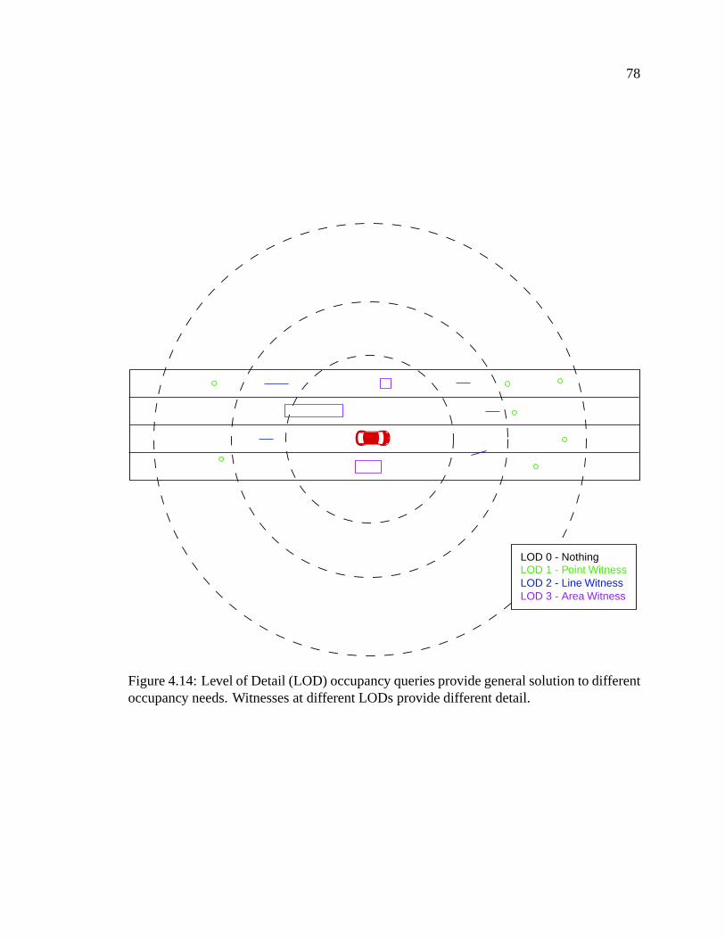
Figure4.14:Level of Detail (LOD) occupancy queriesprovidegeneralsolutionto differentoccupancy needs.Witnessesat differentLODs providedifferentdetail.
79
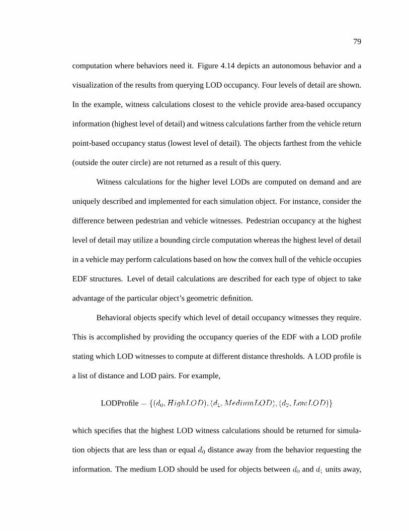
computationwherebehaviors needit. Figure4.14depictsanautonomousbehavior anda
visualizationof theresultsfrom queryingLOD occupancy. Four levelsof detailareshown.
In the example,witnesscalculationsclosestto the vehicleprovide area-basedoccupancy
information(highestlevel of detail)andwitnesscalculationsfartherfrom thevehiclereturn
point-basedoccupancy status(lowestlevel of detail).Theobjectsfarthestfrom thevehicle
(outsidetheoutercircle) arenot returnedasa resultof this query.
Witnesscalculationsfor the higherlevel LODs arecomputedon demandandare
uniquelydescribedandimplementedfor eachsimulationobject.For instance,considerthe
differencebetweenpedestrianandvehiclewitnesses.Pedestrianoccupancy at thehighest
level of detailmayutilize aboundingcirclecomputationwhereasthehighestlevel of detail
in avehiclemayperformcalculationsbasedonhow theconvex hull of thevehicleoccupies
EDF structures.Level of detail calculationsaredescribedfor eachtype of objectto take
advantageof theparticularobject’sgeometricdefinition.
Behavioral objectsspecifywhich level of detailoccupancy witnessesthey require.
This is accomplishedby providing theoccupancy queriesof theEDF with a LOD profile
statingwhichLOD witnessesto computeatdifferentdistancethresholds.A LOD profile is
a list of distanceandLOD pairs.For example,
LODProfile$ E � W �H� R d `�� 9i7 � � � W � �H� ) W R�(a\ � 9i7 � � � W � � � �5j � 9�7 �,J
which specifiesthat thehighestLOD witnesscalculationsshouldbe returnedfor simula-
tion objectsthatarelessthanor equalW distanceaway from thebehavior requestingthe
information. ThemediumLOD shouldbeusedfor objectsbetweenW and
W � unitsaway,
80
RoadQuerieslist y Witnessz "%$
LOD queryObjects(distance, LODProfile )Returnsroadoccupancy witnessesbasedon theLODProfileandthedistanceparameters
list y Witnessz "%$LOD queryObjectsInLane(lane ref, distance, LODProfile )
Returnslaneoccupancy witnessesbasedon theLODProfileanddistanceparameters
Witness"%$
LOD queryLeader(distance, ori, LODProfile )Returnsawitnessbasedon theLODProfilethatrepresentsthenext objectin thedirectionspecifiedby ori afteraparticulardistancealongtheroad
Witness"%$
LOD queryLeaderInLane(lane ref, distance, ori, LODProfile )Returnsawitnessbasedon theLODProfilerepresentingtheleaderoccupantwithin a lane
Intersection Querieslist y Witnessz "%$
LOD queryObjects(��!
, LODProfile )Returnswitnessesbasedon theLODProfileandthedistancebetweentheintersectionoccupantsandtheCartesianvectorprovidedasaparameter
list y Witnessz "%$LOD queryObjectsInCorridor(Corridor, distance,
width,LODProfile )On demandquerythatcalculatestheoccupantswithin a specifiedwidth of thecorridoraxisusingtheLODProfileanddistancealongthecorridor
Witness"%$
queryLeaderInCorridor(Corridor, width,distance, ori, LODProfile )On demandquerythatcalculatestheleaderwitnessaheadof agivendistanceonacorridorusingtheLODProfile
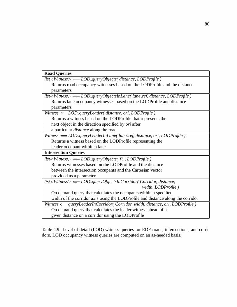
Table4.9: Level of detail (LOD) witnessqueriesfor EDF roads,intersections,andcorri-dors.LOD occupancy witnessqueriesarecomputedon anas-neededbasis.

81
andthe lowestLOD calculationshouldbeperformedfor objectsbetweenW � and
W � units
away. SimulationobjectsbeyondW � units away arenot returnedaswitnesses.Table4.9
lists the different level of detail (LOD) witnessoccupancy queriesprovided by EDF for
roads,intersections,andcorridors.
4.6 Paths
Throughoutthis chapter, I have usedthe word path asa genericdescriptionfor a
navigablerouteusedby simulationobjects. In the EDF, the word path hasmorespecific
meaningdenotinganabstractiondesignedto supportthecontinuousandsmoothnavigation
of objectsover theroadnetworks. For theremainderof this chaptertheword pathwill be
usedasit pertainsto this restrictedmeaning.
A pathprovidesa meansfor trackingandfollowing objectson a lane-basedroute
over sectionsof the road networks. Pathsare intendedto be usedfor local navigation,
providing immediateinformationabouttherouteandtheoccupantsalongthatroute.Paths
arecomposedof anorderedsequenceof (road,lane)pairsand(intersection,corridor)pairs.
Pathsmanagetheir aggregatepartsto presenta single lane-basedcurvilinearcoordinate
system.Pathsdo for lanesandcorridorswhat roadsdo for lists of segments(seeSection
4.3).
Thepathabstractionis adesigndecisioninfluencedpurelyby behavior modelingis-
suesdealingwith intersections.With regardsto vehiclebehaviors,intersectionsaredifficult
to navigate.This is evenmoresofor pedestrianbehaviors usinghierarchicalintersections.
A singlepatheliminatesthemanagerialtasksrequiredby a behavior to negotiatecomplex

82
Intersection Boundary Geometry
Figure4.15: Illustrationof pathuseby vehicles.Threepathsareshown for threedifferentvehicles.Thepathscrossinto andthroughtheintersectionboundary.
intersections,andallows autonomousbehaviors to utilize fewer trackingmechanismsto
drive over roadnetworks. In otherwords, the pathstructureencapsulatesthe important
behavioral propertiesnecessaryfor navigatinga route.
Figure 4.15 illustratesthreevehiclesapproachingan intersection. Eachvehicle
utilizesa pathto seamlesslyintegratetheconnectionbetweenthelanethey areon andthe
corridorthroughtheintersection.
4.6.1 PathAugmentationandQueries
Pathssimplify bookkeepingneededto managefrequentchangesin coordinatesys-
tems.As intersectionsareapproached,pathsgrow andshrinkby addingon theupcoming
corridorsandlaneswhile removing the lanesandcorridorsat the beginning of the path.

83
Tracking Queries� ��� ��� "%$ queryXY(
�� )
Convertsfrom Cartesianto curvilinearspace��! ="%$queryDO( � ��� ��� )
Convertsfrom curvilinearto Cartesianspace.Featureand RangeAttrib ute Querieslist y RangeAttrz "%$
queryRangeAttributes( � ��� �3� )Returnsa list of rangeattributesalongthepath
list y Featurez "%$queryFeatures( � ��� ��� � � � { � � { � � v )
Returna list of featuresalongthepathincludingreferencestostoplineandcurbcorridorattributes
WitnessQuerieslist y Witnessz "%$
LOD queryObjects(�, LODProfile )
Returnswitnessesoccupancy informationfor thepathbasedon theLODProfileandthegivendistanceparameter(
�)
Witness">$
LOD queryLeader(�, ori, LODProfile )
Returnsa witnessbasedon theLODProfilethatrepresentsthenext objectin thedirectionspecifiedby ori afteraparticulardistance,
�, alongthepath
Table4.10:Queriesprovidedby pathsin theEDF.
Pathscanbebuilt incrementally, on anasneededbasisby behaviors, usingtheaugmenta-
tion routinesfor appendingandremoving from thepath.Thus,apathis notmerelyastatic
descriptionof a route. Although pathscanbe usedto describespecificroutesandplans
for autonomousbehaviors, theintendeduseof thepathis asa local, relativedescriptionof
thesurfaceof the route. Pathsarelanebasedandnot roadbased.It is up to behaviors to
augmentandcreatepathsasneeded.For instance,duringa lanechange,thepathmayhave
to bereconstructedby thebehavior. Table4.10lists thequeriesprovidedby thepathstruc-
turesin theEDF. Becausethepathrepresentsa curvilinearsurfacedescription,thequeries
providedby curvilinearsurfacesarealsosuppliedby thepath,asdiscussedin Section4.2.