beginner hard surface guide
TRANSCRIPT

1 | P a g e
A Beginners Guide to Hard Surface Sculpting Using 3DS Max and Zbrush Luke Gamble 2011
2 | P a g e
Forward:
This guide will cover:
A few tips and tricks for smoothing groups in 3DS Max
Transferring hard edges on your OBJ file from 3DS Max to Zbrush
Basic sculpting techniques for Zbrush hard surface sculpting and custom brush creation
How to take information from a Zbrush sculpt and add it to a diffuse map
What you will need:
Any semi-recent copy of 3DS Max (I’m using 2011)
Zbrush 4
Any semi-recent copy of Photoshop (I’m using CS5)
What this guide is NOT:
A tutorial on Zspheres or mesh creation using Zbrush. I’ll be starting from a model made in 3DS
Max for this guide, as it is my preferred workflow.
The be-all, end-all “only way to do it” tutorial for hard surfaces in Zbrush. I’m merely sharing my
workflow, and hopefully somebody out there will find it helpful in some way!
CONTENTS
3DS Max Smoothing Groups and Other Tips Page 03
Exporting for Zbrush Page 09
Preserving Smoothing Groups via Notepad Page 10
Importing OBJs and Hard Edges into Zbrush Page 12
Zbrush Hard Surface Sculpting Page 16
Creating Stamps and Custom Brushes Page 25
Exporting Zbrush Texture Maps Page 30
Acknowledgments Page 33

3 | P a g e
3DS Max Smoothing Groups and Other Tips
3DS Max is an extraordinary program and I highly recommend it for modeling purposes! It’s
relatively easy to learn compared to other 3D programs, and the modifier stack puts many of the
modeling tools that you’ll need in a single down menu. This guide will primarily focus on a workflow
from 3DS Max to Zbrush, but Maya is perfectly capable of getting the job done too. (It’ll just be harder
to follow along because the terminology and functions of the two modeling programs can get pretty
divergent!)
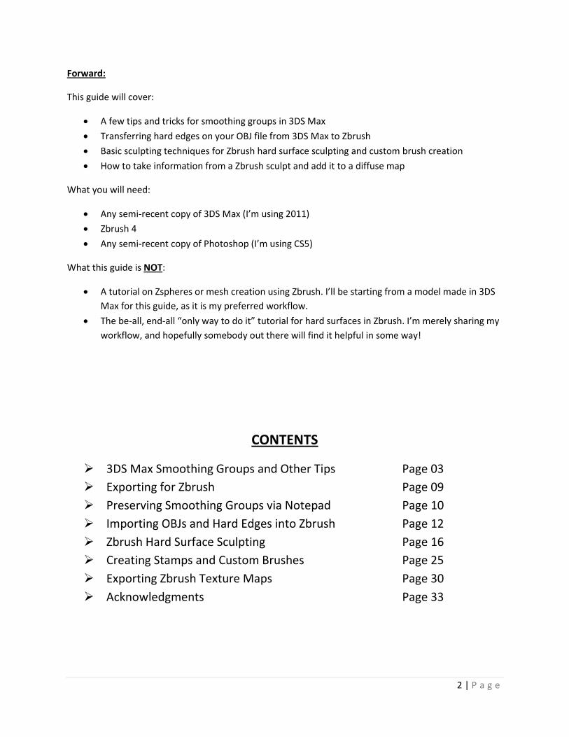
For this project, I decided on a vehicle, so I took a design I had in mind for an independent game
project and got a little creative with the viewport schematics:
From here, I set up the Top and Side viewports using planes in 3DS Max. I modeled the ship
using basic tools only: Inset, Extrude, and Chamfer (used sparingly of course!). All of the parts of the
ship are Editable Polys made from either basic cylinders or boxes. Lastly, because both of the wings are
symmetrical, I only modeled half of the ship (more on this later).
4 | P a g e
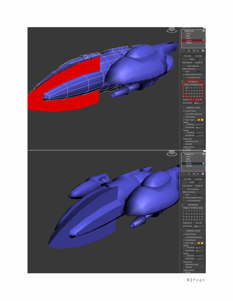
As you can see, the results so far are pretty bland. The vehicle lacks the sharp curves befitting a
truly futuristic spaceship!
So, to give it those hard edges we’re going to use Smoothing Groups. Enter Polygon selection
mode on the Editable Poly of your choice and scroll down the toolbar until you reach Smoothing Groups
(you may have to expand the window by pressing the little “+” sign). From here, you can make polygon
selections and assign a Smoothing Group. You are given a large amount of groups, but realistically you
probably won’t need any more than four or five; this is because all you need to create a hard edge is two
different smoothing groups touching.
In other words, it won’t matter if you use Smoothing Group 12 for one portion of the vehicle
and then use it again somewhere else, just so long as two sets of polys that you have designated as
Group 12 aren’t directly next to each other or touching in any way (because if they did, they’d blend
together instead of creating a hard edge).
In the example below you can see how big of a difference just a few Smoothing Group
assignments can make! It may seem a little tedious at first, but the results will pay off in the end, trust
me.
5 | P a g e
6 | P a g e
However, while you may want to keep the amount of Smoothing Group designations low just to
avoid confusions, do take note of the Select By SG button just below the list of groups. You can use this
later on while UV unwrapping to select entire smoothing groups at once, so it may behoove you to
strategically plan your Smoothing Group designations.
For example, I may give every polygon that I know will be glass on my ship a designation of
Smoothing Group 2. For everything that will be chrome, Smoothing Group 1. For everything that will be
painted metal, Smoothing Group 7, and so on and so forth. That way, when I want to select all of the
glass on my ship for a planar map while UV unrwapping, or something like that, I can simply hit Select By
SG and then select “2” instead of individualy clicking on every single polygon than needs to be the same
material. Pretty neat, huh?
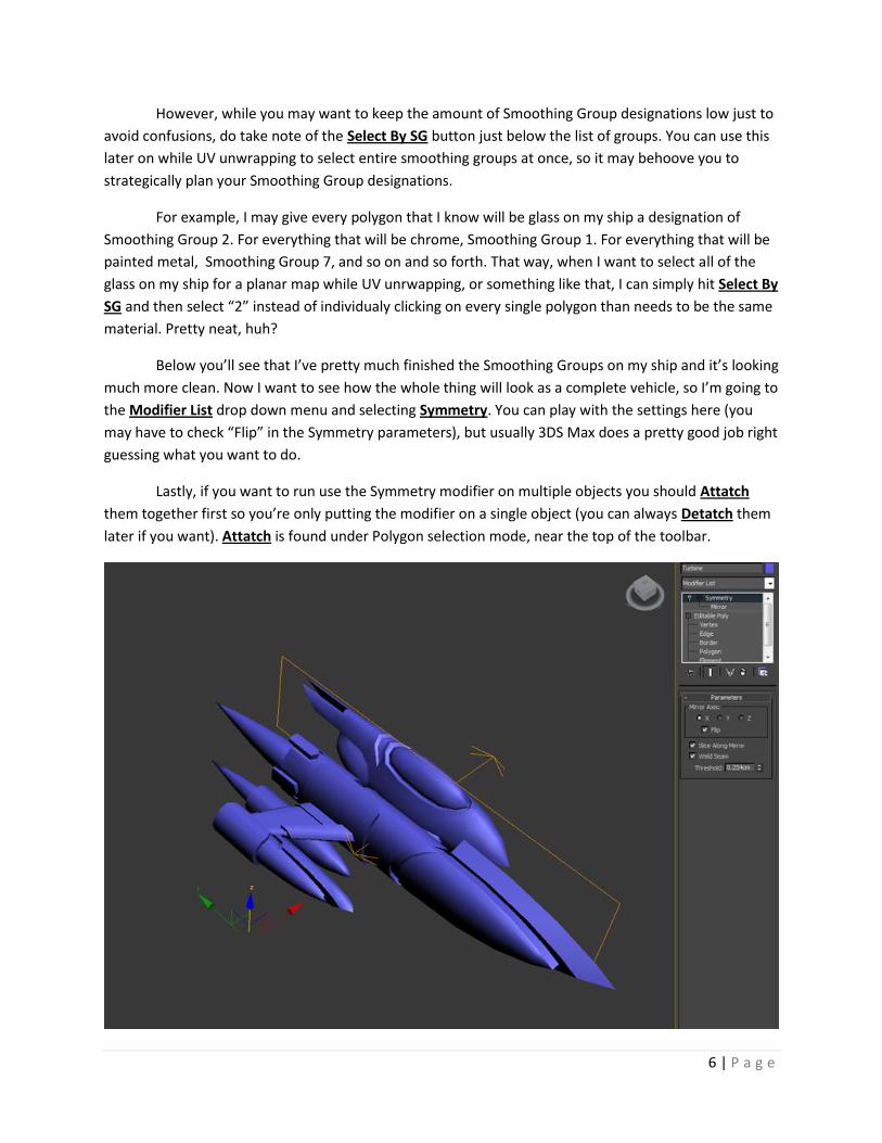
Below you’ll see that I’ve pretty much finished the Smoothing Groups on my ship and it’s looking
much more clean. Now I want to see how the whole thing will look as a complete vehicle, so I’m going to
the Modifier List drop down menu and selecting Symmetry. You can play with the settings here (you
may have to check “Flip” in the Symmetry parameters), but usually 3DS Max does a pretty good job right
guessing what you want to do.
Lastly, if you want to run use the Symmetry modifier on multiple objects you should Attatch
them together first so you’re only putting the modifier on a single object (you can always Detatch them
later if you want). Attatch is found under Polygon selection mode, near the top of the toolbar.
7 | P a g e
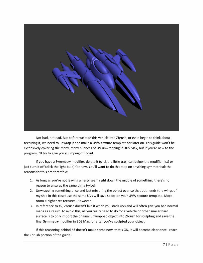
Not bad, not bad. But before we take this vehicle into Zbrush, or even begin to think about
texturing it, we need to unwrap it and make a UVW texture template for later on. This guide won’t be
extensively covering the many, many nuances of UV unwrapping in 3DS Max, but if you’re new to the
program, I’ll try to give you a jumping off point.
If you have a Symmetry modifier, delete it (click the little trashcan below the modifier list) or
just turn it off (click the light bulb) for now. You’ll want to do this step on anything symmetrical; the
reasons for this are threefold:
1. As long as you’re not leaving a nasty seam right down the middle of something, there’s no
reason to unwrap the same thing twice!
2. Unwrapping something once and just mirroring the object over so that both ends (the wings of
my ship in this case) use the same UVs will save space on your UVW texture template. More
room = higher res textures! However…
3. In reference to #2, Zbrush doesn’t like it when you stack UVs and will often give you bad normal
maps as a result. To avoid this, all you really need to do for a vehicle or other similar hard
surface is to only import the original unwrapped object into Zbrush for sculpting and save the
final Symmetry modifier in 3DS Max for after you’ve sculpted your object.
If this reasoning behind #3 doesn’t make sense now, that’s OK, it will become clear once I reach
the Zbrush portion of the guide!
8 | P a g e
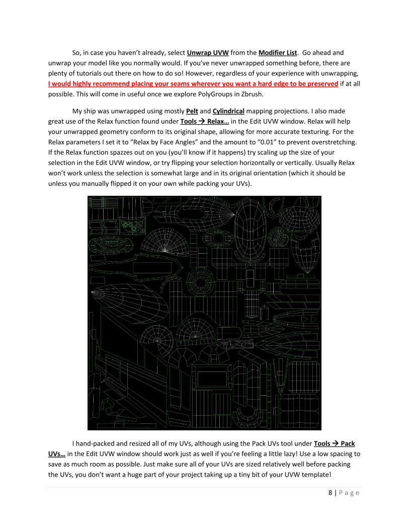
So, in case you haven’t already, select Unwrap UVW from the Modifier List. Go ahead and
unwrap your model like you normally would. If you’ve never unwrapped something before, there are
plenty of tutorials out there on how to do so! However, regardless of your experience with unwrapping,
I would highly recommend placing your seams wherever you want a hard edge to be preserved if at all
possible. This will come in useful once we explore PolyGroups in Zbrush.
My ship was unwrapped using mostly Pelt and Cylindrical mapping projections. I also made
great use of the Relax function found under Tools Relax… in the Edit UVW window. Relax will help
your unwrapped geometry conform to its original shape, allowing for more accurate texturing. For the
Relax parameters I set it to “Relax by Face Angles” and the amount to “0.01” to prevent overstretching.
If the Relax function spazzes out on you (you’ll know if it happens) try scaling up the size of your
selection in the Edit UVW window, or try flipping your selection horizontally or vertically. Usually Relax
won’t work unless the selection is somewhat large and in its original orientation (which it should be
unless you manually flipped it on your own while packing your UVs).
I hand-packed and resized all of my UVs, although using the Pack UVs tool under Tools Pack
UVs… in the Edit UVW window should work just as well if you’re feeling a little lazy! Use a low spacing to
save as much room as possible. Just make sure all of your UVs are sized relatively well before packing
the UVs, you don’t want a huge part of your project taking up a tiny bit of your UVW template!
9 | P a g e
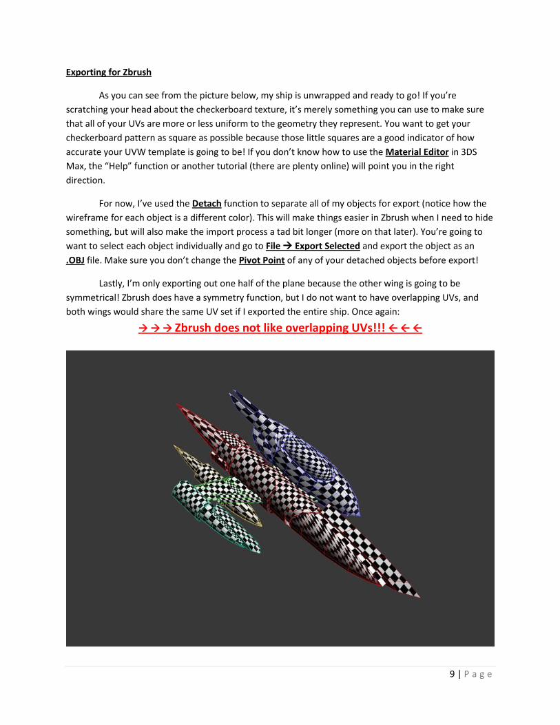
Exporting for Zbrush
As you can see from the picture below, my ship is unwrapped and ready to go! If you’re
scratching your head about the checkerboard texture, it’s merely something you can use to make sure
that all of your UVs are more or less uniform to the geometry they represent. You want to get your
checkerboard pattern as square as possible because those little squares are a good indicator of how
accurate your UVW template is going to be! If you don’t know how to use the Material Editor in 3DS
Max, the “Help” function or another tutorial (there are plenty online) will point you in the right
direction.
For now, I’ve used the Detach function to separate all of my objects for export (notice how the
wireframe for each object is a different color). This will make things easier in Zbrush when I need to hide
something, but will also make the import process a tad bit longer (more on that later). You’re going to
want to select each object individually and go to File Export Selected and export the object as an
.OBJ file. Make sure you don’t change the Pivot Point of any of your detached objects before export!
Lastly, I’m only exporting out one half of the plane because the other wing is going to be
symmetrical! Zbrush does have a symmetry function, but I do not want to have overlapping UVs, and
both wings would share the same UV set if I exported the entire ship. Once again:
Zbrush does not like overlapping UVs!!!
10 | P a g e
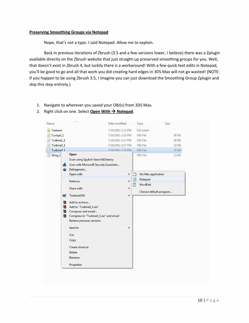
Preserving Smoothing Groups via Notepad
Nope, that’s not a typo. I said Notepad. Allow me to explain.
Back in previous iterations of Zbrush (3.5 and a few versions lower, I believe) there was a Zplugin
available directly on the Zbrush website that just straight-up preserved smoothing groups for you. Well,
that doesn’t exist in Zbrush 4, but luckily there is a workaround! With a few quick text edits in Notepad,
you’ll be good to go and all that work you did creating hard edges in 3DS Max will not go wasted! (NOTE:
If you happen to be using Zbrush 3.5, I imagine you can just download the Smoothing Group Zplugin and
skip this step entirely.)
1. Navigate to wherever you saved your OBJ(s) from 3DS Max.
2. Right click on one. Select Open With Notepad.
11 | P a g e
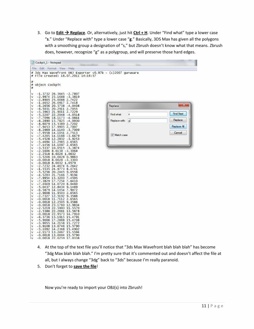
3. Go to Edit Replace. Or, alternatively, just hit Ctrl + H. Under “Find what” type a lower case
“s.” Under “Replace with” type a lower case “g.” Basically, 3DS Max has given all the polygons
with a smoothing group a designation of “s,” but Zbrush doesn’t know what that means. Zbrush
does, however, recognize “g” as a polygroup, and will preserve those hard edges.
4. At the top of the text file you’ll notice that “3ds Max Wavefront blah blah blah” has become
“3dg Max blah blah blah.” I’m pretty sure that it’s commented out and doesn’t affect the file at
all, but I always change “3dg” back to “3ds” because I’m really paranoid.
5. Don’t forget to save the file!
Now you’re ready to import your OBJ(s) into Zbrush!
12 | P a g e
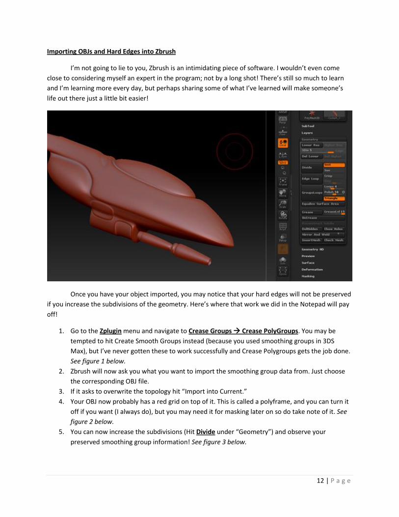
Importing OBJs and Hard Edges into Zbrush
I’m not going to lie to you, Zbrush is an intimidating piece of software. I wouldn’t even come
close to considering myself an expert in the program; not by a long shot! There’s still so much to learn
and I’m learning more every day, but perhaps sharing some of what I’ve learned will make someone’s
life out there just a little bit easier!
Once you have your object imported, you may notice that your hard edges will not be preserved
if you increase the subdivisions of the geometry. Here’s where that work we did in the Notepad will pay
off!
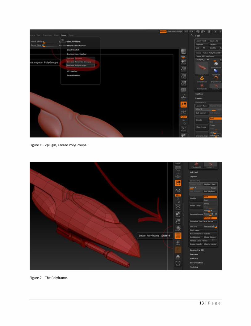
1. Go to the Zplugin menu and navigate to Crease Groups Crease PolyGroups. You may be
tempted to hit Create Smooth Groups instead (because you used smoothing groups in 3DS
Max), but I’ve never gotten these to work successfully and Crease Polygroups gets the job done.
See figure 1 below.
2. Zbrush will now ask you what you want to import the smoothing group data from. Just choose
the corresponding OBJ file.
3. If it asks to overwrite the topology hit “Import into Current.”
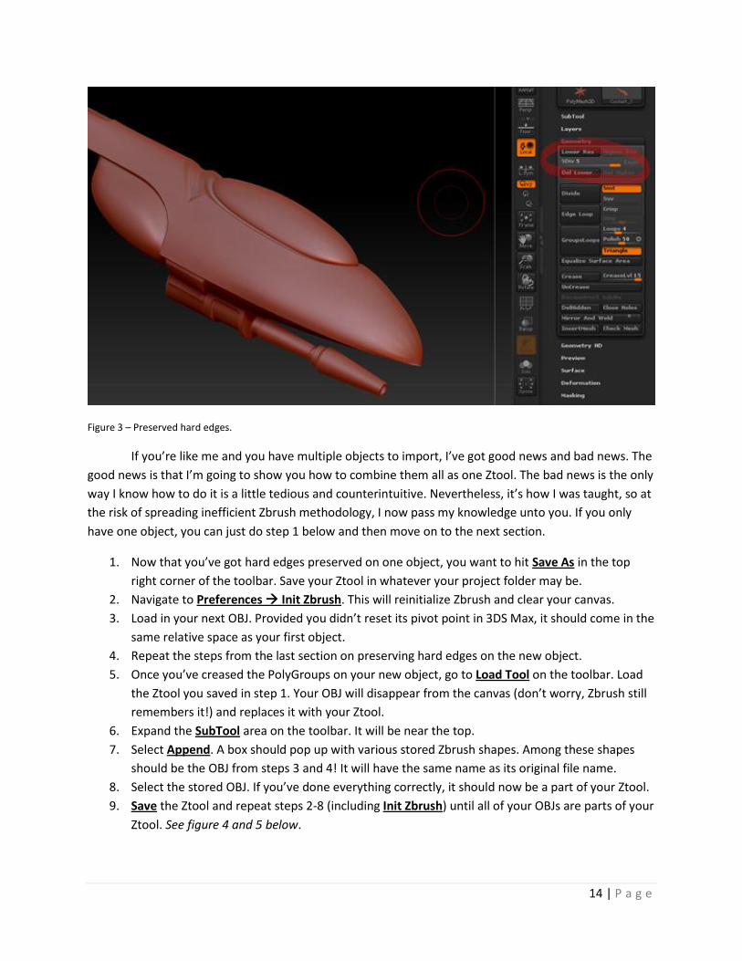
4. Your OBJ now probably has a red grid on top of it. This is called a polyframe, and you can turn it
off if you want (I always do), but you may need it for masking later on so do take note of it. See
figure 2 below.
5. You can now increase the subdivisions (Hit Divide under “Geometry”) and observe your
preserved smoothing group information! See figure 3 below.
13 | P a g e
Figure 1 – Zplugin, Crease PolyGroups.
Figure 2 – The Polyframe.
14 | P a g e
Figure 3 – Preserved hard edges.
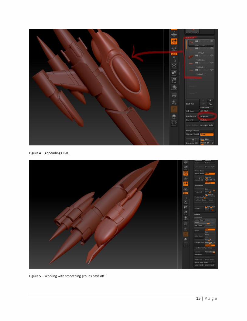
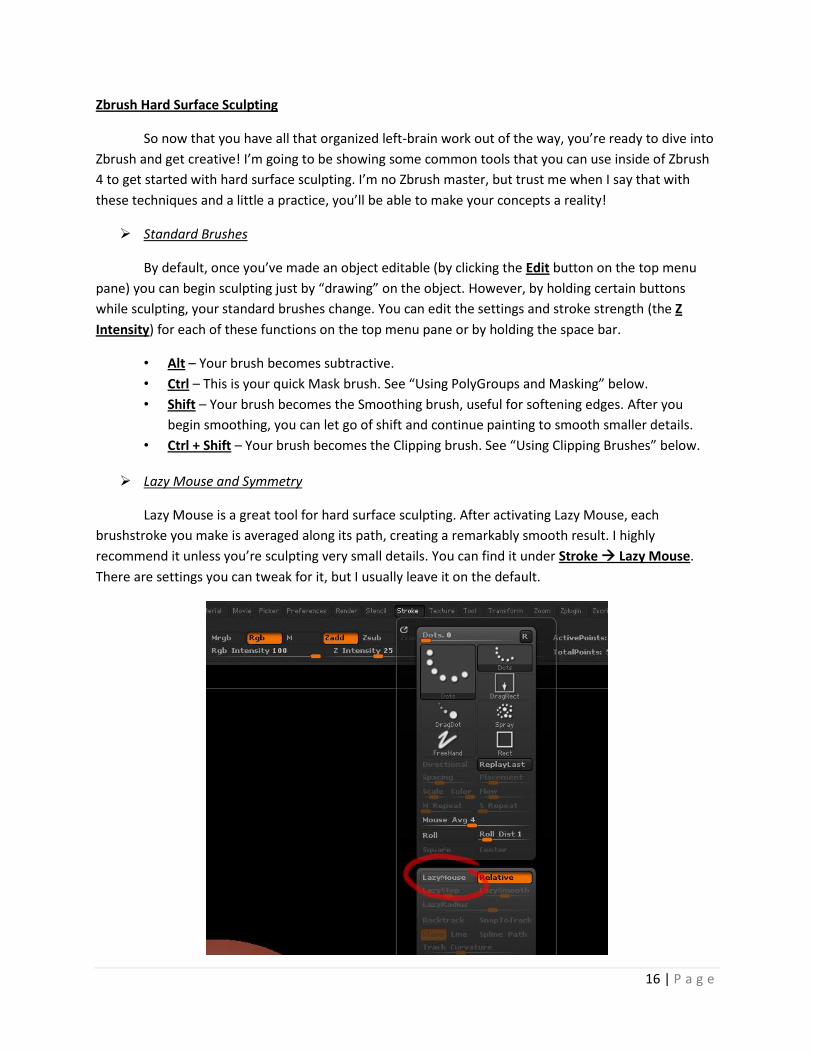
If you’re like me and you have multiple objects to import, I’ve got good news and bad news. The
good news is that I’m going to show you how to combine them all as one Ztool. The bad news is the only
way I know how to do it is a little tedious and counterintuitive. Nevertheless, it’s how I was taught, so at
the risk of spreading inefficient Zbrush methodology, I now pass my knowledge unto you. If you only
have one object, you can just do step 1 below and then move on to the next section.
1. Now that you’ve got hard edges preserved on one object, you want to hit Save As in the top
right corner of the toolbar. Save your Ztool in whatever your project folder may be.
2. Navigate to Preferences Init Zbrush. This will reinitialize Zbrush and clear your canvas.
3. Load in your next OBJ. Provided you didn’t reset its pivot point in 3DS Max, it should come in the
same relative space as your first object.
4. Repeat the steps from the last section on preserving hard edges on the new object.
5. Once you’ve creased the PolyGroups on your new object, go to Load Tool on the toolbar. Load
the Ztool you saved in step 1. Your OBJ will disappear from the canvas (don’t worry, Zbrush still
remembers it!) and replaces it with your Ztool.
6. Expand the SubTool area on the toolbar. It will be near the top.
7. Select Append. A box should pop up with various stored Zbrush shapes. Among these shapes
should be the OBJ from steps 3 and 4! It will have the same name as its original file name.
8. Select the stored OBJ. If you’ve done everything correctly, it should now be a part of your Ztool.
9. Save the Ztool and repeat steps 2-8 (including Init Zbrush) until all of your OBJs are parts of your
Ztool. See figure 4 and 5 below.
15 | P a g e
Figure 4 – Appending OBJs.
Figure 5 – Working with smoothing groups pays off!
16 | P a g e
Zbrush Hard Surface Sculpting
So now that you have all that organized left-brain work out of the way, you’re ready to dive into
Zbrush and get creative! I’m going to be showing some common tools that you can use inside of Zbrush
4 to get started with hard surface sculpting. I’m no Zbrush master, but trust me when I say that with
these techniques and a little a practice, you’ll be able to make your concepts a reality!
Standard Brushes
By default, once you’ve made an object editable (by clicking the Edit button on the top menu
pane) you can begin sculpting just by “drawing” on the object. However, by holding certain buttons
while sculpting, your standard brushes change. You can edit the settings and stroke strength (the Z
Intensity) for each of these functions on the top menu pane or by holding the space bar.
• Alt – Your brush becomes subtractive.
• Ctrl – This is your quick Mask brush. See “Using PolyGroups and Masking” below.
• Shift – Your brush becomes the Smoothing brush, useful for softening edges. After you
begin smoothing, you can let go of shift and continue painting to smooth smaller details.
• Ctrl + Shift – Your brush becomes the Clipping brush. See “Using Clipping Brushes” below.
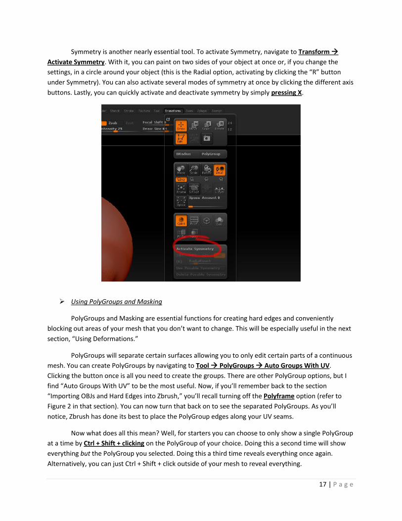
Lazy Mouse and Symmetry
Lazy Mouse is a great tool for hard surface sculpting. After activating Lazy Mouse, each
brushstroke you make is averaged along its path, creating a remarkably smooth result. I highly
recommend it unless you’re sculpting very small details. You can find it under Stroke Lazy Mouse.
There are settings you can tweak for it, but I usually leave it on the default.
17 | P a g e
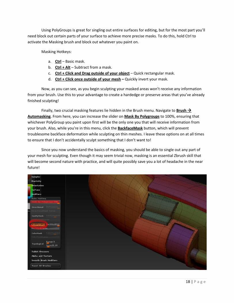
Symmetry is another nearly essential tool. To activate Symmetry, navigate to Transform
Activate Symmetry. With it, you can paint on two sides of your object at once or, if you change the
settings, in a circle around your object (this is the Radial option, activating by clicking the “R” button
under Symmetry). You can also activate several modes of symmetry at once by clicking the different axis
buttons. Lastly, you can quickly activate and deactivate symmetry by simply pressing X.
Using PolyGroups and Masking
PolyGroups and Masking are essential functions for creating hard edges and conveniently
blocking out areas of your mesh that you don’t want to change. This will be especially useful in the next
section, “Using Deformations.”
PolyGroups will separate certain surfaces allowing you to only edit certain parts of a continuous
mesh. You can create PolyGroups by navigating to Tool PolyGroups Auto Groups With UV.
Clicking the button once is all you need to create the groups. There are other PolyGroup options, but I
find “Auto Groups With UV” to be the most useful. Now, if you’ll remember back to the section
“Importing OBJs and Hard Edges into Zbrush,” you’ll recall turning off the Polyframe option (refer to
Figure 2 in that section). You can now turn that back on to see the separated PolyGroups. As you’ll
notice, Zbrush has done its best to place the PolyGroup edges along your UV seams.
Now what does all this mean? Well, for starters you can choose to only show a single PolyGroup
at a time by Ctrl + Shift + clicking on the PolyGroup of your choice. Doing this a second time will show
everything but the PolyGroup you selected. Doing this a third time reveals everything once again.
Alternatively, you can just Ctrl + Shift + click outside of your mesh to reveal everything.
18 | P a g e
Using PolyGroups is great for singling out entire surfaces for editing, but for the most part you’ll
need block out certain parts of your surface to achieve more precise masks. To do this, hold Ctrl to
activate the Masking brush and block out whatever you paint on.
Masking Hotkeys:
a. Ctrl – Basic mask.
b. Ctrl + Alt – Subtract from a mask.
c. Ctrl + Click and Drag outside of your object – Quick rectangular mask.
d. Ctrl + Click once outside of your mesh – Quickly invert your mask.
Now, as you can see, as you begin sculpting your masked areas won’t receive any information
from your brush. Use this to your advantage to create a hardedge or preserve areas that you’ve already
finished sculpting!
Finally, two crucial masking features lie hidden in the Brush menu. Navigate to Brush
Automasking. From here, you can increase the slider on Mask By Polygroups to 100%, ensuring that
whichever PolyGroup you paint upon first will be the only one you that will receive information from
your brush. Also, while you’re in this menu, click the BackfaceMask button, which will prevent
troublesome backface deformation while sculpting on thin meshes. I leave these options on at all times
to ensure that I don’t accidentally sculpt something that I don’t want to!
Since you now understand the basics of masking, you should be able to single out any part of
your mesh for sculpting. Even though it may seem trivial now, masking is an essential Zbrush skill that
will become second nature with practice, and will quite possibly save you a lot of headache in the near
future!
19 | P a g e
Using Deformations
Deformations are extremely useful for creating interesting effects over the entirety of your
mesh (or at least the areas that are not masked out). You can find the Deformation pane on the Toolbar
docked to the right, just below “Surface.”
There are many different deformations that can be applied to your mesh, although you’re only
likely to use a few of them. For quick transformations that won’t require the finicky Zbrush Move,
Rotate, or Scale tools, you can use Offset or Rotate or Size deformations. Noise and Smooth will
respectively add a rough texture or remove detail from your mesh. Out of all of the Deformers, you’ll
likely use Inflate most of all; it does exactly what it sounds like, but works best with masking to make
extrusions along a surface.
Deformation and masking go hand in hand. Often times, you won’t want the change the entirely
of a mesh. Try masking off an area before inflating or sizing your mesh and observe the results. For
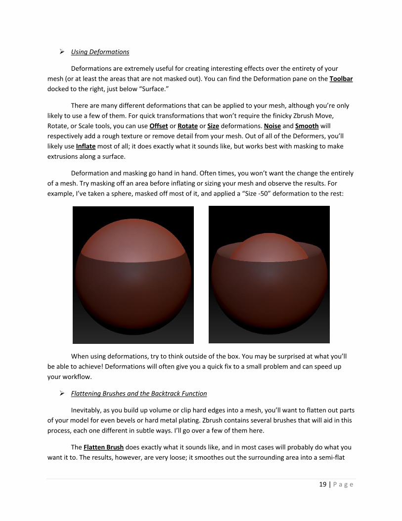
example, I’ve taken a sphere, masked off most of it, and applied a “Size -50” deformation to the rest:
When using deformations, try to think outside of the box. You may be surprised at what you’ll
be able to achieve! Deformations will often give you a quick fix to a small problem and can speed up
your workflow.
Flattening Brushes and the Backtrack Function
Inevitably, as you build up volume or clip hard edges into a mesh, you’ll want to flatten out parts
of your model for even bevels or hard metal plating. Zbrush contains several brushes that will aid in this
process, each one different in subtle ways. I’ll go over a few of them here.
The Flatten Brush does exactly what it sounds like, and in most cases will probably do what you
want it to. The results, however, are very loose; it smoothes out the surrounding area into a semi-flat
20 | P a g e
surface. It is most useful in conjunction with the Clay Tubes brush to add volume early on in a project.
Consider it a good “concepting” brush, but not a “finished product” brush.
There are a few useful Planar Brushes, although for the most part, planar brushes are better for
precise geometric sculpting. For starters, PlanarCut and PlanarCutThin will make a flattened cut on the
surface of your model. PlanarFlatten, however, creates a flat circular layer directly over your existing
mesh; it’s great for making a quick metal plate. The PlanarLine and PlanarSpline, and all variations
therein, are useful for flattening or cutting in a straight line or in a circle; move your brush one direction
to “draw” your path, then the opposite direction to sculpt a line, or radially to create a circle (the line
you just drew as a path will become the circumference).
When you need to simply flatten something, I find that the Polish Brushes will give you the best
results in the shortest time. Polish will simply polish and flatten, while hPolish will use your tablet’s pen
pressure to designate how much to polish and flatten. Whereas the Flatten brush was for concepting,
hPolish is for the finished product!
Lastly, are the Trim Brushes, which create the most dynamic effects. TrimAdaptive will average
out the flatness of the surfaces around it, and works best by slowly and carefully drawing its path. Trim
Dynamic gives lots of control with the direction you want to flatten, but will sometimes cut too deeply
or leave an unwanted hard edge if you’re not careful; it’s a useful brush that takes a trained hand.
TrimDynamicTrails works similar to Trim Dynamic, only it will try to conform to a singular path; it will
usually produce decent, if a bit uneven, bevels between two hard edges.
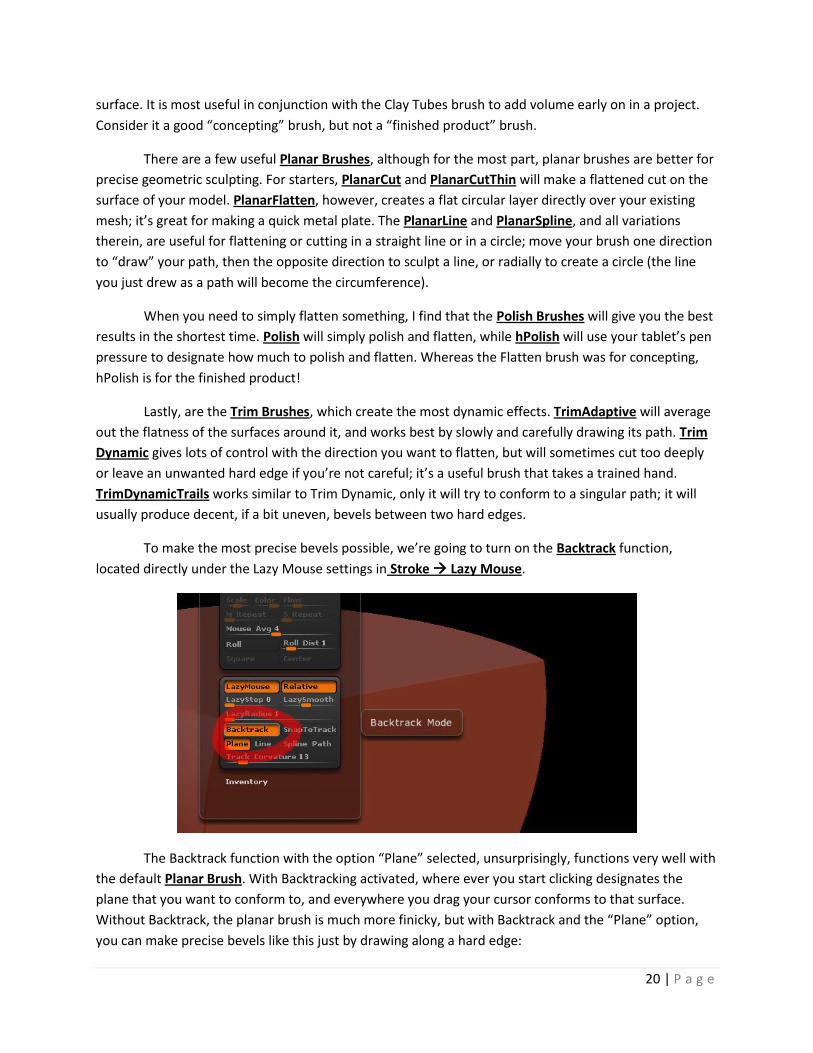
To make the most precise bevels possible, we’re going to turn on the Backtrack function,
located directly under the Lazy Mouse settings in Stroke Lazy Mouse.
The Backtrack function with the option “Plane” selected, unsurprisingly, functions very well with
the default Planar Brush. With Backtracking activated, where ever you start clicking designates the
plane that you want to conform to, and everywhere you drag your cursor conforms to that surface.
Without Backtrack, the planar brush is much more finicky, but with Backtrack and the “Plane” option,
you can make precise bevels like this just by drawing along a hard edge:
21 | P a g e
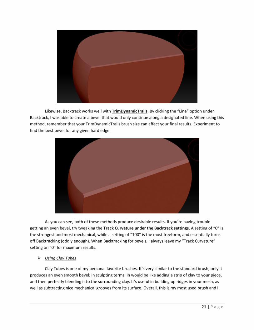
Likewise, Backtrack works well with TrimDynamicTrails. By clicking the “Line” option under
Backtrack, I was able to create a bevel that would only continue along a designated line. When using this
method, remember that your TrimDynamicTrails brush size can affect your final results. Experiment to
find the best bevel for any given hard edge:
As you can see, both of these methods produce desirable results. If you’re having trouble
getting an even bevel, try tweaking the Track Curvature under the Backtrack settings. A setting of “0” is
the strongest and most mechanical, while a setting of “100” is the most freeform, and essentially turns
off Backtracking (oddly enough). When Backtracking for bevels, I always leave my “Track Curvature”
setting on “0” for maximum results.
Using Clay Tubes
Clay Tubes is one of my personal favorite brushes. It’s very similar to the standard brush, only it
produces an even smooth bevel; in sculpting terms, in would be like adding a strip of clay to your piece,
and then perfectly blending it to the surrounding clay. It’s useful in building up ridges in your mesh, as
well as subtracting nice mechanical grooves from its surface. Overall, this is my most used brush and I
22 | P a g e
highly recommend practicing with it! Even if you aren’t planning on making mechanical cuts into your
mesh, Clay Tubes is still useful for building up volume on organic shapes.
Like all brushes, holding shift after beginning your stroke will snap it to the vertical or
horizontal axis. This is good for creating mechanical grating or vents in your mesh. See the figure below.
Clay tubes work best when followed up with the Smoothing brush to soften the edges further,
or with one of the flattening brushes mentioned above to create a nice even surface on top of your new
volume (I like the HPolish brush). Also, make sure to tweak your brush settings; try changing the Alpha,
Intensity, or Focal Shift to get that perfect bevel on your Clay Tubes. Making good use of rectangular
masking can also be helpful when trying to fill a square area with volume.
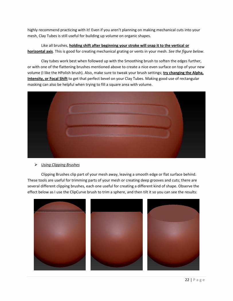
Using Clipping Brushes
Clipping Brushes clip part of your mesh away, leaving a smooth edge or flat surface behind.
These tools are useful for trimming parts of your mesh or creating deep grooves and cuts; there are
several different clipping brushes, each one useful for creating a different kind of shape. Observe the
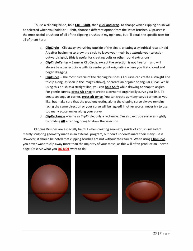
effect below as I use the ClipCurve brush to trim a sphere, and then tilt it so you can see the results:
23 | P a g e
To use a clipping brush, hold Ctrl + Shift, then click and drag. To change which clipping brush will
be selected when you hold Ctrl + Shift, choose a different option from the list of brushes. ClipCurve is
the most useful brush out of all of the clipping brushes in my opinions, but I’ll detail the specific uses for
all of them here:
a. ClipCircle – Clip away everything outside of the circle, creating a cylindrical result. Hold
Alt after beginning to draw the circle to leave your mesh but extrude your selection
outward slightly (this is useful for creating bolts or other round extrusions).
b. ClipCircleCenter – Same as ClipCircle, except the selection is not freeform and will
always be a perfect circle with its center point originating where you first clicked and
began dragging.
c. ClipCurve – The most diverse of the clipping brushes, ClipCurve can create a straight line
to clip along (as seen in the images above), or create an organic or angular curve. While
using this brush as a straight line, you can hold Shift while drawing to snap to angles.
For gentle curves, press Alt once to create a corner to organically curve your line. To
create an angular corner, press alt twice. You can create as many curve corners as you
like, but make sure that the gradient resting along the clipping curve always remains
facing the same direction or your curve will be jagged! In other words, never try to use
too many acute angles along your curve.
d. ClipRectangle – Same as ClipCircle, only a rectangle. Can also extrude surfaces slightly
by holding Alt after beginning to draw the selection.
Clipping Brushes are especially helpful when creating geometry inside of Zbrush instead of
merely sculpting geometry made in an external program, but don’t underestimate their many uses!
However, it should be noted that clipping brushes are not without their faults. When using ClipCurve,
you never want to clip away more than the majority of your mesh, as this will often produce an uneven
edge. Observe what you DO NOT want to do:
24 | P a g e
Don’t do that. That’s an uneven edge that you just do not want to deal with later on. To avoid it,
simply clip away the minority of the mesh, instead of the majority.
And lastly, I’ll leave you with two final tips for Clipping Brushes:
1. Hold Space Bar While Drawing – Move the clipping selection around. Release space bar
to lock it in place.
2. Hold Ctrl + Shift + Space Before Drawing – Brings up two useful additional options for
clipping brushes: BRadius and PolyGroups. BRadius will only clip an area proportional to
your brush size, creating useful insets. PolyGroups will make ever surface you make
with your clipping brushes into a new PolyGroup.
If nothing else, try keeping the PolyGroups option on for a while when clipping with your
ClipCurve brush. You might be surprised at how easy it makes masking out your new surfaces (refer to
the section Using PolyGroups and Masking for more tips).
In Summary
Now that you’ve been introduced to just a few of the complex interconnected functions of
Zbrush 4, you should be well on your way to creating an amazing hard surface sculpture. Take the
techniques that you’ve learned here and apply them!
25 | P a g e
Creating Stamps and Custom Brushes
When sculpting your mesh, the small details often end up becoming too tedious to sculpt
individually. To that end, Zbrush has a wide assortment of custom brush options to make your life a lot
easier! For things like screws, you can make a simple brush to place detail once per brushstroke (in other
words, a Stamp). For more continuous details, like seams or scratches, an effective custom brush can be
created just by tweaking a few settings.
To start things off, navigate to the Brush Pane on the left of your screen (by default, or you can
hold down space bar to bring it up over your cursor). Below your brush selection box are options for
Stroke and Alpha. Right now, we’re interested in the “Stroke” box, so click on it and observe. If you’re
using a Standard brush, chances are the Stroke is set to “Dots.” Here are the differences between the
stroke options:
a. Dots – Takes the shape of the brush and paints it as several overlapping dots. For most regular
brushes, this is the default.
b. DragRect – Clicking and dragging with this option takes the basic shape of the brush and scales it
out from where you began dragging. Somewhat useful for non-uniform stamps.
c. Freehand – Similar to Dots. Stretches the shape of the brush out into a freeform line, following
your brushstroke.
d. Color Spray – Random assortment of brush shapes in varying intensities. Useful for non-uniform
noise.
e. Spray – Random assortment of brush shapes in the same intensity. Useful for noise.
f. DragDot – Creates the brush shape in a uniform size relative to the brush size. This is essentially
what you’ll be using for Stamps.
Now that we’ve got all of the basics for brush strokes out of the way, we can get to the fun part.
However, creating a Stamp for a screw or bolt is a very step-intensive process:
1. Turn off Perspective Distortion if it is on (Press “P”).
2. Navigate to Document Width and Height. Change the size to 512 x 512. Hit Resize.
3. Draw a Plane3D on the canvas (hold Space and select it in the top box above the brush box).
Make it editable, and then hit Make PolyMesh3D (you can find this in Tools under your “Save”
and “Load” options).
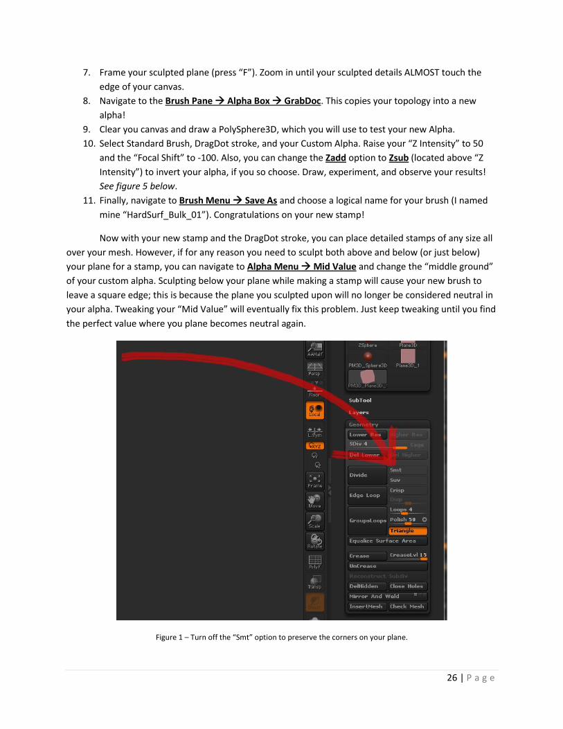
4. Navigate to Geometry under Tools. Unclick the Smt (smooth) button and divide the subdivisions
to about 3 or 4. See Figure 1 below.
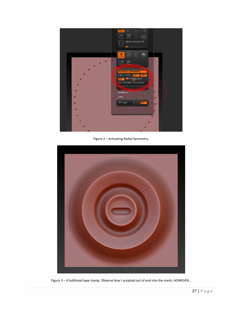
5. Navigate to Transform Activate Symmetry. Turn on Radial symmetry (“R”) on the Z axis (“Z”)
with a “Radial Count” of 30-40 for a nice smooth edge. See figure 2 below.
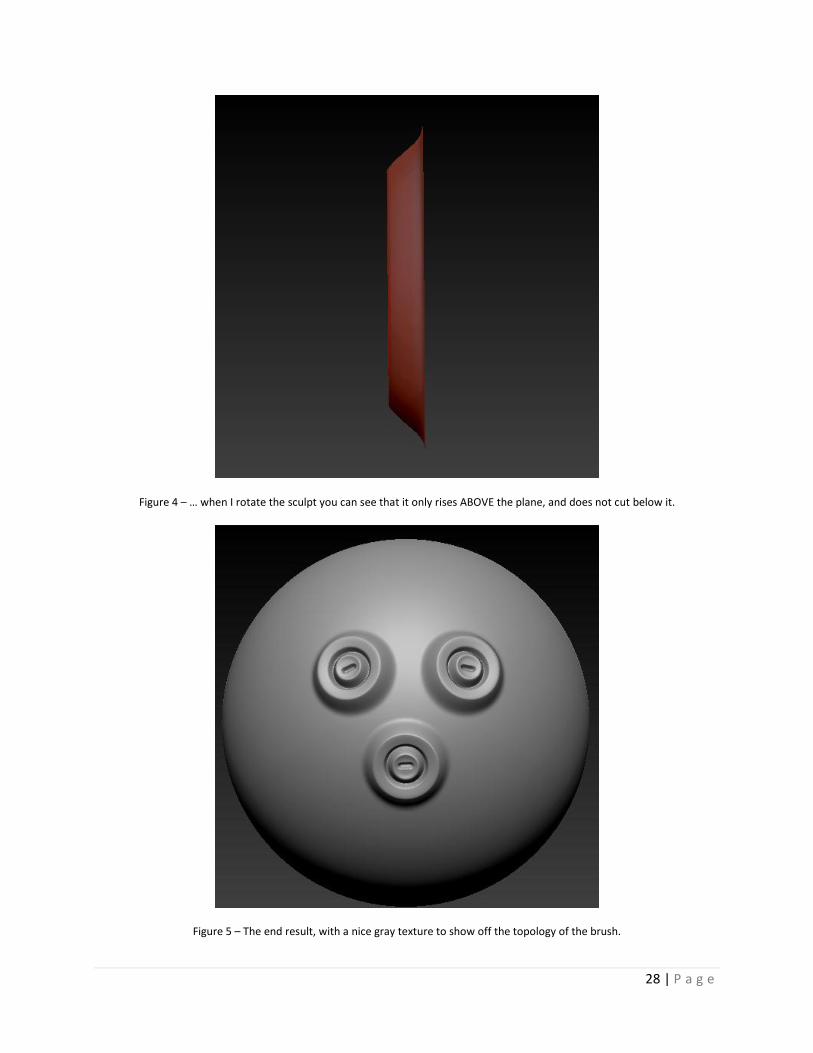
6. Sculpt whatever you like into the plane! This will become your stamp, so make sure you are
happy with the results. Sculpt near the edge with your details, but don’t touch the edge of the
plane. Also, if at all possible, make your sculpt only positive. In other words, only sculpt above
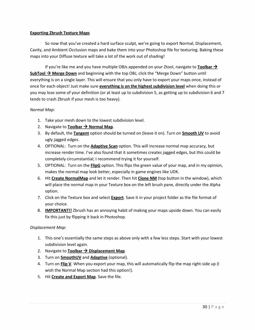
your plane, don’t cut below it. I’ll explain the reasons for this later, but following this general
rule will save time in the end. See figures 3 and 4 below.
26 | P a g e
7. Frame your sculpted plane (press “F”). Zoom in until your sculpted details ALMOST touch the
edge of your canvas.
8. Navigate to the Brush Pane Alpha Box GrabDoc. This copies your topology into a new
alpha!
9. Clear you canvas and draw a PolySphere3D, which you will use to test your new Alpha.
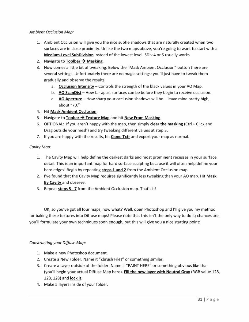
10. Select Standard Brush, DragDot stroke, and your Custom Alpha. Raise your “Z Intensity” to 50
and the “Focal Shift” to -100. Also, you can change the Zadd option to Zsub (located above “Z
Intensity”) to invert your alpha, if you so choose. Draw, experiment, and observe your results!
See figure 5 below.
11. Finally, navigate to Brush Menu Save As and choose a logical name for your brush (I named
mine “HardSurf_Bulk_01”). Congratulations on your new stamp!
Now with your new stamp and the DragDot stroke, you can place detailed stamps of any size all
over your mesh. However, if for any reason you need to sculpt both above and below (or just below)
your plane for a stamp, you can navigate to Alpha Menu Mid Value and change the “middle ground”
of your custom alpha. Sculpting below your plane while making a stamp will cause your new brush to
leave a square edge; this is because the plane you sculpted upon will no longer be considered neutral in
your alpha. Tweaking your “Mid Value” will eventually fix this problem. Just keep tweaking until you find
the perfect value where you plane becomes neutral again.
Figure 1 – Turn off the “Smt” option to preserve the corners on your plane.
27 | P a g e
Figure 2 – Activating Radial Symmetry.
Figure 3 – A bulkhead type stamp. Observe how I sculpted out of and into the mesh; HOWEVER…
28 | P a g e
Figure 4 – … when I rotate the sculpt you can see that it only rises ABOVE the plane, and does not cut below it.
Figure 5 – The end result, with a nice gray texture to show off the topology of the brush.

29 | P a g e
For seams, like the kind you would get on futuristic metal plating, I use a downloadable brush
known as Dam_Standard. See the “Acknowledgements” section for the download link. However, to
make a custom brush, you can realistically use the same techniques you just learned for stamps! For
example, sculpting a small, hard-edged dot on a stamp will result in a precise, mechanical seam when
you use it as a brush with the “Dots” or “Freehand” stroke style. Here are a couple other cool features
for creating custom brushes:
Stroke Menu Roll. This option will effectively “roll” a straight-lined alpha over itself again and
again, creating a nearly seamlessly tiling stroke of your brush. Try it with the Lazy Mouse “Lazy
Step” option set to “0.1” and the brush stroke set to “Freehand.” Alternatively, try it with a dot
instead of a line to create bolted seams in your metal!
Alpha Menu H Tiles / V Tiles. With these options you can tile an alpha horizontally and
vertically. This is extremely useful for creating a metal mesh or rubber tire tread. Use it with the
“DragRect” brush stroke.
If you find that you just can’t get that perfect Alpha in Zbrush, keep in mind you can always paint
one in Photoshop and load that grayscale image as a custom brush! Just try to make sure your edges are
black.
30 | P a g e
Exporting Zbrush Texture Maps
So now that you’ve created a hard surface sculpt, we’re going to export Normal, Displacement,
Cavity, and Ambient Occlusion maps and bake them into your Photoshop file for texturing. Baking these
maps into your Diffuse texture will take a lot of the work out of shading!
If you’re like me and you have multiple OBJs appended on your Ztool, navigate to Toolbar
SubTool Merge Down and beginning with the top OBJ, click the “Merge Down” button until
everything is on a single layer. This will ensure that you only have to export your maps once, instead of
once for each object! Just make sure everything is on the highest subdivision level when doing this or
you may lose some of your definition (or at least up to subdivision 5, as getting up to subdivision 6 and 7
tends to crash Zbrush if your mesh is too heavy).
Normal Map:
1. Take your mesh down to the lowest subdivision level.
2. Navigate to Toolbar Normal Map.
3. By default, the Tangent option should be turned on (leave it on). Turn on Smooth UV to avoid
ugly jagged edges.
4. OPTIONAL: Turn on the Adaptive Scan option. This will increase normal map accuracy, but
increase render time. I’ve also found that it sometimes creates jagged edges, but this could be
completely circumstantial; I recommend trying it for yourself.
5. OPTIONAL: Turn on the FlipG option. This flips the green value of your map, and in my opinion,
makes the normal map look better, especially in game engines like UDK.
6. Hit Create NormalMap and let it render. Then hit Clone NM (top button in the window), which
will place the normal map in your Texture box on the left brush pane, directly under the Alpha
option.
7. Click on the Texture box and select Export. Save it in your project folder as the file format of
your choice.
8. IMPORTANT!! Zbrush has an annoying habit of making your maps upside down. You can easily
fix this just by flipping it back in Photoshop.
Displacement Map:
1. This one’s essentially the same steps as above only with a few less steps. Start with your lowest
subdivision level again.
2. Navigate to Toolbar Displacement Map.
3. Turn on SmoothUV and Adaptive (optional).
4. Turn on Flip V. When you export your map, this will automatically flip the map right-side up (I
wish the Normal Map section had this option!).
5. Hit Create and Export Map. Save the file.
31 | P a g e
Ambient Occlusion Map:
1. Ambient Occlusion will give you the nice subtle shadows that are naturally created when two
surfaces are in close proximity. Unlike the two maps above, you’re going to want to start with a
Medium-Level SubDivision instead of the lowest level. SDiv 4 or 5 usually works.
2. Navigate to Toolbar Masking.
3. Now comes a little bit of tweaking. Below the “Mask Ambient Occlusion” button there are
several settings. Unfortunately there are no magic settings; you’ll just have to tweak them
gradually and observe the results:
a. Occlusion Intensity – Controls the strength of the black values in your AO Map.
b. AO ScanDist – How far apart surfaces can be before they begin to receive occlusion.
c. AO Aperture – How sharp your occlusion shadows will be. I leave mine pretty high,
about “70.”
4. Hit Mask Ambient Occlusion.
5. Navigate to Toobar Texture Map and hit New From Masking.
6. OPTIONAL: If you aren’t happy with the map, then simply clear the masking (Ctrl + Click and
Drag outside your mesh) and try tweaking different values at step 3.
7. If you are happy with the results, hit Clone Txtr and export your map as normal.
Cavity Map:
1. The Cavity Map will help define the darkest darks and most prominent recesses in your surface
detail. This is an important map for hard surface sculpting because it will often help define your
hard edges! Begin by repeating steps 1 and 2 from the Ambient Occlusion map.
2. I’ve found that the Cavity Map requires significantly less tweaking than your AO map. Hit Mask
By Cavity and observe.
3. Repeat steps 5 - 7 from the Ambient Occlusion map. That’s it!
OK, so you’ve got all four maps, now what? Well, open Photoshop and I’ll give you my method
for baking these textures into Diffuse maps! Please note that this isn’t the only way to do it; chances are
you’ll formulate your own techniques soon enough, but this will give you a nice starting point:
Constructing your Diffuse Map:
1. Make a new Photoshop document.
2. Create a New Folder. Name it “Zbrush Files” or something similar.
3. Create a Layer outside of the folder. Name it “PAINT HERE” or something obvious like that
(you’ll begin your actual Diffuse Map here). Fill the new layer with Neutral Gray (RGB value 128,
128, 128) and lock it.
4. Make 5 layers inside of your folder.
32 | P a g e
5. From top to bottom, name them (something similar to):
a. UV Temp
b. Cav
c. Occ
d. Disp
e. Nrm
6. Open all of your exported Zbrush maps in Photoshop. Flip them if necessary (it probably will be
on everything but the Displacement Map if you followed the steps above). Resize them to a
power of 2 if necessary (usually Zbrush likes to make maps 2048x2048, and I resize them to
1024x1024 for the Diffuse Map).
7. Paste or place the flipped and resized Zbrush maps into their respective layers. Paste or place
your UV Template (remember way back in the 3DS Max section?) on the top layer.
8. Change the Blending Mode and Opacity for each of the layers:
a. UV Temp – Invert (Ctrl + I). Your template will be white with black lines now. Change
Blending Mode to Multiply. Change Opacity to 10%.
b. Cav – Change Blending Mode to Overlay. Change Opacity to 70-80%.
c. Occ – Change Blending Mode to Soft Light. Change Opacity to 70-80%.
d. Disp – Change Blending Mode to Multiply or Overlay. Change Opacity to 70-100%.
e. Nrm – Change Blending Mode to Luminosity. Change Opacity to 50-60%.
9. Make Adjustment Layers where necessary (Layer New Adjustment Layer… Check “Use
Previous Layer to Create Clipping Mask”). You will most likely need to tweak the Levels or
Brightness/Contrast on you Cav, Occ, and Disp layers.
10. Your Nrm Layer may wash out your color a little because of Luminosity. If this is the case, make
an Adjustment Layer with Hue/Saturation and lower its “Lightness” until you still have the
detail without washing out your colors. Lowering the opacity can also work.
From here, you should have a good start with which to begin painting your Diffuse Map. As
always, don’t be afraid to tweak your settings; experiment with blending modes and opacities until you
find the setting that’s perfect for your project.
This section concludes the tutorial. Thank you for your time, and I hope you found it helpful.
Best of luck to you in your future projects!

33 | P a g e
Acknowledgments
This tutorial is free to use and replicate. Spread the knowledge!
This tutorial was made in association with FIEA: http://www.fiea.ucf.edu
Luke Gamble’s website: http://www.awalloftext.com
To create creases in my projects, I use Maddam's Standard brush (always referred to as
“Dam_Standard” in online circles). You should too! Download the brush here:
http://www.zbrushcentral.com/showthread.php?t=57944&page=6&pp=15
If you’re having trouble finding where to save the brush file, navigate to Brush Menu Load
Brush and copy the path.
Thanks for reading! I hope that you found this tutorial useful in some way. If you have any
comments, please share them at:
http://awalloftext.weebly.com/contact.html