beaweblogic server - oracle · beaweblogic server ® using weblogic server clusters version 10.0...
TRANSCRIPT

BEAWebLogic Server®
Using WebLogic Server Clusters
Version 10.0Revised: March 30, 2007


Using WebLogic Server Clusters iii
Contents
1. Introduction and RoadmapDocument Scope and Audience . . . . . . . . . . . . . . . . . . . . . . . . . . . . . . . . . . . . . . . . . . . . . 1-1
Guide to this Document . . . . . . . . . . . . . . . . . . . . . . . . . . . . . . . . . . . . . . . . . . . . . . . . . . . 1-2
Related Documentation . . . . . . . . . . . . . . . . . . . . . . . . . . . . . . . . . . . . . . . . . . . . . . . . . . . 1-2
New and Changed Clustering Features in This Release . . . . . . . . . . . . . . . . . . . . . . . . . . 1-2
2. Understanding WebLogic Server ClusteringWhat Is a WebLogic Server Cluster?. . . . . . . . . . . . . . . . . . . . . . . . . . . . . . . . . . . . . . . . . 2-1
How Does a Cluster Relate to a Domain? . . . . . . . . . . . . . . . . . . . . . . . . . . . . . . . . . . . . . 2-2
What Are the Benefits of Clustering? . . . . . . . . . . . . . . . . . . . . . . . . . . . . . . . . . . . . . . . . 2-3
What Are the Key Capabilities of a Cluster? . . . . . . . . . . . . . . . . . . . . . . . . . . . . . . . . . . . 2-3
What Types of Objects Can Be Clustered? . . . . . . . . . . . . . . . . . . . . . . . . . . . . . . . . . . . . 2-5
Servlets and JSPs . . . . . . . . . . . . . . . . . . . . . . . . . . . . . . . . . . . . . . . . . . . . . . . . . . . . 2-6
EJBs and RMI Objects . . . . . . . . . . . . . . . . . . . . . . . . . . . . . . . . . . . . . . . . . . . . . . . . 2-6
JDBC Connections . . . . . . . . . . . . . . . . . . . . . . . . . . . . . . . . . . . . . . . . . . . . . . . . . . . 2-6
Getting Connections with Clustered JDBC . . . . . . . . . . . . . . . . . . . . . . . . . . . . . 2-7
Failover and Load Balancing for JDBC Connections . . . . . . . . . . . . . . . . . . . . . 2-8
JMS and Clustering. . . . . . . . . . . . . . . . . . . . . . . . . . . . . . . . . . . . . . . . . . . . . . . . . . . 2-8
What Types of Objects Cannot Be Clustered?. . . . . . . . . . . . . . . . . . . . . . . . . . . . . . . . . . 2-8
3. Communications In a ClusterWebLogic Server Communication In a Cluster . . . . . . . . . . . . . . . . . . . . . . . . . . . . . . . . . 3-1
Using IP Multicast for Backward Compatibility . . . . . . . . . . . . . . . . . . . . . . . . . . . . 3-2
iv Using WebLogic Server Clusters
Multicast and Cluster Configuration. . . . . . . . . . . . . . . . . . . . . . . . . . . . . . . . . . 3-2
One-to-Many Communication Using Unicast . . . . . . . . . . . . . . . . . . . . . . . . . . . . . . 3-4
Unicast Configuration. . . . . . . . . . . . . . . . . . . . . . . . . . . . . . . . . . . . . . . . . . . . . 3-4
Considerations When Using Unicast . . . . . . . . . . . . . . . . . . . . . . . . . . . . . . . . . 3-5
Peer-to-Peer Communication Using IP Sockets . . . . . . . . . . . . . . . . . . . . . . . . . . . . 3-5
Pure-Java Versus Native Socket Reader Implementations . . . . . . . . . . . . . . . . . 3-6
Configuring Reader Threads for Java Socket Implementation. . . . . . . . . . . . . . 3-7
Client Communication via Sockets . . . . . . . . . . . . . . . . . . . . . . . . . . . . . . . . . . . . . 3-10
Cluster-Wide JNDI Naming Service. . . . . . . . . . . . . . . . . . . . . . . . . . . . . . . . . . . . . . . . 3-10
How WebLogic Server Creates the Cluster-Wide JNDI Tree . . . . . . . . . . . . . . . . . 3-11
How JNDI Naming Conflicts Occur . . . . . . . . . . . . . . . . . . . . . . . . . . . . . . . . . . . . 3-13
Deploy Homogeneously to Avoid Cluster-Level JNDI Conflicts . . . . . . . . . . 3-14
How WebLogic Server Updates the JNDI Tree . . . . . . . . . . . . . . . . . . . . . . . . . . . . 3-14
Client Interaction with the Cluster-Wide JNDI Tree . . . . . . . . . . . . . . . . . . . . . . . . 3-14
4. Understanding Cluster ConfigurationCluster Configuration and config.xml. . . . . . . . . . . . . . . . . . . . . . . . . . . . . . . . . . . . . . . . 4-1
Role of the Administration Server . . . . . . . . . . . . . . . . . . . . . . . . . . . . . . . . . . . . . . . . . . 4-2
What Happens if the Administration Server Fails? . . . . . . . . . . . . . . . . . . . . . . . . . . 4-3
How Dynamic Configuration Works . . . . . . . . . . . . . . . . . . . . . . . . . . . . . . . . . . . . . . . . 4-4
Application Deployment for Clustered Configurations . . . . . . . . . . . . . . . . . . . . . . . . . . 4-4
Deployment Methods . . . . . . . . . . . . . . . . . . . . . . . . . . . . . . . . . . . . . . . . . . . . . . . . . 4-4
Introduction to Two-Phase Deployment . . . . . . . . . . . . . . . . . . . . . . . . . . . . . . . . . . 4-5
First Phase of Deployment . . . . . . . . . . . . . . . . . . . . . . . . . . . . . . . . . . . . . . . . . 4-5
Second Phase of Deployment . . . . . . . . . . . . . . . . . . . . . . . . . . . . . . . . . . . . . . . 4-6
Guidelines for Deploying to a Cluster . . . . . . . . . . . . . . . . . . . . . . . . . . . . . . . . . . . . 4-6
WebLogic Server Supports “Relaxed Deployment” Rules. . . . . . . . . . . . . . . . . 4-7
Methods of Configuring Clusters . . . . . . . . . . . . . . . . . . . . . . . . . . . . . . . . . . . . . . . . . . . 4-8

Using WebLogic Server Clusters v
5. Load Balancing in a ClusterLoad Balancing for Servlets and JSPs . . . . . . . . . . . . . . . . . . . . . . . . . . . . . . . . . . . . . . . . 5-1
Load Balancing with a Proxy Plug-in . . . . . . . . . . . . . . . . . . . . . . . . . . . . . . . . . . . . 5-2
How Session Connection and Failover Work with a Proxy Plug-in . . . . . . . . . . 5-2
Load Balancing HTTP Sessions with an External Load Balancer . . . . . . . . . . . . . . . 5-2
Load Balancer Configuration Requirements. . . . . . . . . . . . . . . . . . . . . . . . . . . . 5-2
Load Balancers and the WebLogic Session Cookie . . . . . . . . . . . . . . . . . . . . . . 5-3
Related Programming Considerations. . . . . . . . . . . . . . . . . . . . . . . . . . . . . . . . . 5-4
How Session Connection and Failover Works with a Load Balancer. . . . . . . . . 5-4
Load Balancing for EJBs and RMI Objects . . . . . . . . . . . . . . . . . . . . . . . . . . . . . . . . . . . 5-4
Round Robin Load Balancing . . . . . . . . . . . . . . . . . . . . . . . . . . . . . . . . . . . . . . . . . . 5-4
Weight-Based Load Balancing . . . . . . . . . . . . . . . . . . . . . . . . . . . . . . . . . . . . . . . . . . 5-5
Random Load Balancing . . . . . . . . . . . . . . . . . . . . . . . . . . . . . . . . . . . . . . . . . . . . . . 5-6
Server Affinity Load Balancing Algorithms . . . . . . . . . . . . . . . . . . . . . . . . . . . . . . . 5-6
Server Affinity and Initial Context . . . . . . . . . . . . . . . . . . . . . . . . . . . . . . . . . . . 5-7
Server Affinity and IIOP Client Authentication Using CSIv2 . . . . . . . . . . . . . . 5-7
Round-Robin Affinity, Weight-Based Affinity, and Random-Affinity . . . . . . . . 5-8
Parameter-Based Routing for Clustered Objects . . . . . . . . . . . . . . . . . . . . . . . . . . . 5-12
Optimization for Collocated Objects . . . . . . . . . . . . . . . . . . . . . . . . . . . . . . . . . . . . 5-12
Transactional Collocation . . . . . . . . . . . . . . . . . . . . . . . . . . . . . . . . . . . . . . . . . 5-13
Load Balancing for JMS . . . . . . . . . . . . . . . . . . . . . . . . . . . . . . . . . . . . . . . . . . . . . . . . . 5-14
Server Affinity for Distributed JMS Destinations . . . . . . . . . . . . . . . . . . . . . . . . . . 5-14
Initial Context Affinity and Server Affinity for Client Connections . . . . . . . . . . . . 5-15
Load Balancing for JDBC Connections . . . . . . . . . . . . . . . . . . . . . . . . . . . . . . . . . . . . . 5-16
6. Failover and Replication in a ClusterHow WebLogic Server Detects Failures . . . . . . . . . . . . . . . . . . . . . . . . . . . . . . . . . . . . . . 6-1
Failure Detection Using IP Sockets . . . . . . . . . . . . . . . . . . . . . . . . . . . . . . . . . . . . . . 6-2

vi Using WebLogic Server Clusters
The WebLogic Server “Heartbeat” . . . . . . . . . . . . . . . . . . . . . . . . . . . . . . . . . . . . . . 6-2
Replication and Failover for Servlets and JSPs . . . . . . . . . . . . . . . . . . . . . . . . . . . . . . . . 6-2
HTTP Session State Replication . . . . . . . . . . . . . . . . . . . . . . . . . . . . . . . . . . . . . . . . 6-3
Requirements for HTTP Session State Replication . . . . . . . . . . . . . . . . . . . . . . 6-4
Using Replication Groups. . . . . . . . . . . . . . . . . . . . . . . . . . . . . . . . . . . . . . . . . . 6-6
Accessing Clustered Servlets and JSPs Using a Proxy . . . . . . . . . . . . . . . . . . . . . . . 6-9
Proxy Connection Procedure . . . . . . . . . . . . . . . . . . . . . . . . . . . . . . . . . . . . . . . 6-9
Proxy Failover Procedure . . . . . . . . . . . . . . . . . . . . . . . . . . . . . . . . . . . . . . . . . 6-10
Accessing Clustered Servlets and JSPs with Load Balancing Hardware . . . . . . . . 6-11
Connection with Load Balancing Hardware. . . . . . . . . . . . . . . . . . . . . . . . . . . 6-11
Failover with Load Balancing Hardware . . . . . . . . . . . . . . . . . . . . . . . . . . . . . 6-13
Session State Replication Across Clusters in a MAN/WAN . . . . . . . . . . . . . . . . . . 6-14
Network Requirements for Cross-cluster Replication . . . . . . . . . . . . . . . . . . . 6-14
Configuration Requirements for Cross-Cluster Replication. . . . . . . . . . . . . . . 6-16
Configuring Session State Replication Across Clusters . . . . . . . . . . . . . . . . . . 6-18
Configuring a Replication Channel . . . . . . . . . . . . . . . . . . . . . . . . . . . . . . . . . 6-19
MAN HTTP Session State Replication. . . . . . . . . . . . . . . . . . . . . . . . . . . . . . . 6-19
WAN HTTP Session State Replication. . . . . . . . . . . . . . . . . . . . . . . . . . . . . . . 6-22
Replication and Failover for EJBs and RMIs . . . . . . . . . . . . . . . . . . . . . . . . . . . . . . . . . 6-25
Clustering Objects with Replica-Aware Stubs . . . . . . . . . . . . . . . . . . . . . . . . . . . . . 6-26
Clustering Support for Different Types of EJBs . . . . . . . . . . . . . . . . . . . . . . . . . . . 6-27
Clustered EJBHomes . . . . . . . . . . . . . . . . . . . . . . . . . . . . . . . . . . . . . . . . . . . . 6-27
Clustered EJBObjects . . . . . . . . . . . . . . . . . . . . . . . . . . . . . . . . . . . . . . . . . . . . 6-27
Entity EJBs . . . . . . . . . . . . . . . . . . . . . . . . . . . . . . . . . . . . . . . . . . . . . . . . . . . . 6-30
Clustering Support for RMI Objects . . . . . . . . . . . . . . . . . . . . . . . . . . . . . . . . . . . . 6-31
Object Deployment Requirements . . . . . . . . . . . . . . . . . . . . . . . . . . . . . . . . . . . . . . 6-31
Other Failover Exceptions . . . . . . . . . . . . . . . . . . . . . . . . . . . . . . . . . . . . . . . . 6-32
Failover and JDBC Connections . . . . . . . . . . . . . . . . . . . . . . . . . . . . . . . . . . . . . . . . . . . 6-32
Using WebLogic Server Clusters vii
7. Whole Server MigrationUnderstanding Whole Server and Service Migration . . . . . . . . . . . . . . . . . . . . . . . . . . . . 7-1
Migration Terminology . . . . . . . . . . . . . . . . . . . . . . . . . . . . . . . . . . . . . . . . . . . . . . . . . . . 7-2
Leasing. . . . . . . . . . . . . . . . . . . . . . . . . . . . . . . . . . . . . . . . . . . . . . . . . . . . . . . . . . . . . . . . 7-3
Features That Use Leasing . . . . . . . . . . . . . . . . . . . . . . . . . . . . . . . . . . . . . . . . . . . . . 7-3
Leasing Versions. . . . . . . . . . . . . . . . . . . . . . . . . . . . . . . . . . . . . . . . . . . . . . . . . . . . . 7-4
Determining Which Leasing Type to Use . . . . . . . . . . . . . . . . . . . . . . . . . . . . . . . . . 7-5
High-availability Database Leasing . . . . . . . . . . . . . . . . . . . . . . . . . . . . . . . . . . . . . . 7-5
Non-database Consensus Leasing . . . . . . . . . . . . . . . . . . . . . . . . . . . . . . . . . . . . . . . 7-6
Automatic Whole Server Migration . . . . . . . . . . . . . . . . . . . . . . . . . . . . . . . . . . . . . . . . . 7-7
Preparing for Automatic Whole Server Migration. . . . . . . . . . . . . . . . . . . . . . . . . . . 7-7
Configuring Automatic Whole Server Migration. . . . . . . . . . . . . . . . . . . . . . . . . . . . 7-8
Using High Availability Storage for State Data . . . . . . . . . . . . . . . . . . . . . . . . . . . . 7-10
Server Migration Processes and Communications . . . . . . . . . . . . . . . . . . . . . . . . . . 7-10
Startup Process in a Cluster with Migratable Servers . . . . . . . . . . . . . . . . . . . . 7-10
Automatic Migration Process . . . . . . . . . . . . . . . . . . . . . . . . . . . . . . . . . . . . . . 7-12
Manual Migration Process . . . . . . . . . . . . . . . . . . . . . . . . . . . . . . . . . . . . . . . . 7-14
Administration Server’s Role in Whole Server Migration . . . . . . . . . . . . . . . . 7-16
Migratable Server Behavior in a Cluster. . . . . . . . . . . . . . . . . . . . . . . . . . . . . . 7-16
Node Manager’s Role in Whole Server Migration . . . . . . . . . . . . . . . . . . . . . . 7-17
Cluster Master’s Role in Whole Server Migration . . . . . . . . . . . . . . . . . . . . . . 7-18
8. Service-Level MigrationUnderstanding the Service-Level Migration Framework . . . . . . . . . . . . . . . . . . . . . . . . . 8-2
Migratable Services . . . . . . . . . . . . . . . . . . . . . . . . . . . . . . . . . . . . . . . . . . . . . . . . . . 8-2
Messaging/JMS-related Services . . . . . . . . . . . . . . . . . . . . . . . . . . . . . . . . . . . . 8-2
JTA Transaction Recovery Service . . . . . . . . . . . . . . . . . . . . . . . . . . . . . . . . . . . 8-3
User-defined Singleton Services . . . . . . . . . . . . . . . . . . . . . . . . . . . . . . . . . . . . . 8-3

viii Using WebLogic Server Clusters
Understanding Migratable Targets In a Cluster . . . . . . . . . . . . . . . . . . . . . . . . . . . . . 8-4
User-Preferred Servers and Candidate Servers. . . . . . . . . . . . . . . . . . . . . . . . . . 8-4
Targeting Rules for JMS Servers . . . . . . . . . . . . . . . . . . . . . . . . . . . . . . . . . . . . 8-5
Targeting Rules for SAF Agents. . . . . . . . . . . . . . . . . . . . . . . . . . . . . . . . . . . . . 8-5
Targeting Rules for Path Service . . . . . . . . . . . . . . . . . . . . . . . . . . . . . . . . . . . . 8-6
Targeting Rules for Custom Stores . . . . . . . . . . . . . . . . . . . . . . . . . . . . . . . . . . . 8-6
Migratable Targets For the JTA Transaction Recovery Service . . . . . . . . . . . . . 8-6
Migration Processing Tools . . . . . . . . . . . . . . . . . . . . . . . . . . . . . . . . . . . . . . . . . . . . 8-7
Administration Console . . . . . . . . . . . . . . . . . . . . . . . . . . . . . . . . . . . . . . . . . . . 8-7
WebLogic Scripting Tool . . . . . . . . . . . . . . . . . . . . . . . . . . . . . . . . . . . . . . . . . . 8-7
Automatic Service Migration Infrastructure for JTA. . . . . . . . . . . . . . . . . . . . . . . . . 8-7
Leasing for Migratable Services . . . . . . . . . . . . . . . . . . . . . . . . . . . . . . . . . . . . . 8-7
Node Manager. . . . . . . . . . . . . . . . . . . . . . . . . . . . . . . . . . . . . . . . . . . . . . . . . . . 8-8
Service Health Monitoring . . . . . . . . . . . . . . . . . . . . . . . . . . . . . . . . . . . . . . . . . 8-9
Migrating a Service From an Unavailable Server . . . . . . . . . . . . . . . . . . . . . . . . . . . 8-9
Pre-Migration Requirements . . . . . . . . . . . . . . . . . . . . . . . . . . . . . . . . . . . . . . . . . . . . . . 8-10
Custom Store Availability for JMS Services . . . . . . . . . . . . . . . . . . . . . . . . . . . . . . 8-10
Default File Store Availability for JTA . . . . . . . . . . . . . . . . . . . . . . . . . . . . . . . . . . 8-10
Server State and Manual Service Migration . . . . . . . . . . . . . . . . . . . . . . . . . . . . . . 8-11
Roadmap for Configuring Manual Migration of JMS-Related Services . . . . . . . . . . . . 8-13
Step 1: Configured Managed Servers . . . . . . . . . . . . . . . . . . . . . . . . . . . . . . . . . . . 8-13
Step 2: Configure Migratable Targets . . . . . . . . . . . . . . . . . . . . . . . . . . . . . . . . . . . 8-13
Configuring a Migratable Server As a Migratable Target . . . . . . . . . . . . . . . . 8-13
Create a New Migratable Target . . . . . . . . . . . . . . . . . . . . . . . . . . . . . . . . . . . . 8-14
Step 3: Configure and Target Custom Stores . . . . . . . . . . . . . . . . . . . . . . . . . . . . . . 8-15
Step 4: Target the JMS Services. . . . . . . . . . . . . . . . . . . . . . . . . . . . . . . . . . . . . . . . 8-15
Special Considerations When Targeting SAF Agents or Path Service. . . . . . . 8-15

Using WebLogic Server Clusters ix
Step 5: Restart the Administration Server and Managed Servers With Modified Migration Policies . . . . . . . . . . . . . . . . . . . . . . . . . . . . . . . . . . . . . . . . . . . . . . . 8-16
Step 6: Manually Migrating JMS Services. . . . . . . . . . . . . . . . . . . . . . . . . . . . . . . . 8-16
Roadmap for Configuring Automatic Migration of the JTA Transaction Recovery Service .8-17
Step 1: Configured Managed Servers and Node Manager . . . . . . . . . . . . . . . . . . . . 8-17
Step 2: Configure the Migration Basis . . . . . . . . . . . . . . . . . . . . . . . . . . . . . . . . . . . 8-18
Step 3: Enable Automatic JTA Migration . . . . . . . . . . . . . . . . . . . . . . . . . . . . . . . . 8-18
Step 4: Configure the Default Persistent Store For Transaction Recovery Service Migration. . . . . . . . . . . . . . . . . . . . . . . . . . . . . . . . . . . . . . . . . . . . . . . . . . . . . . 8-19
Step 5: Restart the Administration Server and Managed Servers With Modified Migration Policies . . . . . . . . . . . . . . . . . . . . . . . . . . . . . . . . . . . . . . . . . . . . . . . 8-19
Step 6: Automatic Failback of the Transaction Recovery Service Back to the Original Server . . . . . . . . . . . . . . . . . . . . . . . . . . . . . . . . . . . . . . . . . . . . . . . . . . . . . . . . 8-19
Manual Migration of the JTA Transaction Recovery Service. . . . . . . . . . . . . . . . . . . . . 8-21
Automatic Migration of User-Defined Singleton Services . . . . . . . . . . . . . . . . . . . . . . . 8-22
Overview of Singleton Service Migration . . . . . . . . . . . . . . . . . . . . . . . . . . . . . . . . 8-22
Migration Master. . . . . . . . . . . . . . . . . . . . . . . . . . . . . . . . . . . . . . . . . . . . . . . . 8-22
Migration Failure. . . . . . . . . . . . . . . . . . . . . . . . . . . . . . . . . . . . . . . . . . . . . . . . 8-23
Implementing the Singleton Service Interface . . . . . . . . . . . . . . . . . . . . . . . . . . . . . 8-23
Deploying a Singleton Service and Configuring the Migration Behavior . . . . . . . . 8-24
Packaging and Deploying a Singleton Service Within an Application. . . . . . . 8-24
Deploying a Singleton Service As a Standalone Service in WebLogic Server. 8-24
Configuring Singleton Service Migration . . . . . . . . . . . . . . . . . . . . . . . . . . . . . 8-25
9. Cluster ArchitecturesArchitectural and Cluster Terminology . . . . . . . . . . . . . . . . . . . . . . . . . . . . . . . . . . . . . . . 9-1
Architecture . . . . . . . . . . . . . . . . . . . . . . . . . . . . . . . . . . . . . . . . . . . . . . . . . . . . . . . . 9-1
Web Application Tiers . . . . . . . . . . . . . . . . . . . . . . . . . . . . . . . . . . . . . . . . . . . . . . . . 9-1

x Using WebLogic Server Clusters
Combined Tier Architecture . . . . . . . . . . . . . . . . . . . . . . . . . . . . . . . . . . . . . . . . . . . 9-2
De-Militarized Zone (DMZ) . . . . . . . . . . . . . . . . . . . . . . . . . . . . . . . . . . . . . . . . . . . 9-2
Load Balancer . . . . . . . . . . . . . . . . . . . . . . . . . . . . . . . . . . . . . . . . . . . . . . . . . . . . . . 9-3
Proxy Plug-In . . . . . . . . . . . . . . . . . . . . . . . . . . . . . . . . . . . . . . . . . . . . . . . . . . . . . . . 9-3
Recommended Basic Architecture . . . . . . . . . . . . . . . . . . . . . . . . . . . . . . . . . . . . . . . . . . 9-3
When Not to Use a Combined Tier Architecture. . . . . . . . . . . . . . . . . . . . . . . . . . . . 9-5
Recommended Multi-Tier Architecture . . . . . . . . . . . . . . . . . . . . . . . . . . . . . . . . . . . . . . 9-6
Physical Hardware and Software Layers . . . . . . . . . . . . . . . . . . . . . . . . . . . . . . . . . . 9-7
Web/Presentation Layer . . . . . . . . . . . . . . . . . . . . . . . . . . . . . . . . . . . . . . . . . . . 9-7
Object Layer . . . . . . . . . . . . . . . . . . . . . . . . . . . . . . . . . . . . . . . . . . . . . . . . . . . . 9-8
Benefits of Multi-Tier Architecture . . . . . . . . . . . . . . . . . . . . . . . . . . . . . . . . . . . . . . 9-8
Load Balancing Clustered Objects in a in Multi-Tier Architecture . . . . . . . . . . . . . . 9-9
Configuration Considerations for Multi-Tier Architecture . . . . . . . . . . . . . . . . . . . 9-10
IP Socket Usage . . . . . . . . . . . . . . . . . . . . . . . . . . . . . . . . . . . . . . . . . . . . . . . . 9-10
Hardware Load Balancers. . . . . . . . . . . . . . . . . . . . . . . . . . . . . . . . . . . . . . . . . 9-11
Limitations of Multi-Tier Architectures. . . . . . . . . . . . . . . . . . . . . . . . . . . . . . . . . . 9-11
No Collocation Optimization . . . . . . . . . . . . . . . . . . . . . . . . . . . . . . . . . . . . . . 9-11
Firewall Restrictions . . . . . . . . . . . . . . . . . . . . . . . . . . . . . . . . . . . . . . . . . . . . . 9-11
Recommended Proxy Architectures . . . . . . . . . . . . . . . . . . . . . . . . . . . . . . . . . . . . . . . . 9-12
Two-Tier Proxy Architecture . . . . . . . . . . . . . . . . . . . . . . . . . . . . . . . . . . . . . . . . . . 9-12
Physical Hardware and Software Layers . . . . . . . . . . . . . . . . . . . . . . . . . . . . . 9-13
Multi-Tier Proxy Architecture . . . . . . . . . . . . . . . . . . . . . . . . . . . . . . . . . . . . . . . . . 9-14
Proxy Architecture Benefits. . . . . . . . . . . . . . . . . . . . . . . . . . . . . . . . . . . . . . . . . . . 9-15
Proxy Architecture Limitations . . . . . . . . . . . . . . . . . . . . . . . . . . . . . . . . . . . . . . . . 9-16
Proxy Plug-In Versus Load Balancer . . . . . . . . . . . . . . . . . . . . . . . . . . . . . . . . . . . . 9-16
Security Options for Cluster Architectures . . . . . . . . . . . . . . . . . . . . . . . . . . . . . . . . . . . 9-17
Basic Firewall for Proxy Architectures . . . . . . . . . . . . . . . . . . . . . . . . . . . . . . . . . . 9-17
Firewall Between Proxy Layer and Cluster . . . . . . . . . . . . . . . . . . . . . . . . . . . 9-18
Using WebLogic Server Clusters xi
DMZ with Basic Firewall Configurations. . . . . . . . . . . . . . . . . . . . . . . . . . . . . 9-19
Combining Firewall with Load Balancer . . . . . . . . . . . . . . . . . . . . . . . . . . . . . 9-19
Expanding the Firewall for Internal Clients . . . . . . . . . . . . . . . . . . . . . . . . . . . 9-20
Additional Security for Shared Databases . . . . . . . . . . . . . . . . . . . . . . . . . . . . . . . . 9-22
DMZ with Two Firewall Configuration . . . . . . . . . . . . . . . . . . . . . . . . . . . . . . 9-22
10.Setting up WebLogic ClustersBefore You Start . . . . . . . . . . . . . . . . . . . . . . . . . . . . . . . . . . . . . . . . . . . . . . . . . . . . . . . 10-1
Understand the Configuration Process . . . . . . . . . . . . . . . . . . . . . . . . . . . . . . . . . . . 10-1
Determine Your Cluster Architecture. . . . . . . . . . . . . . . . . . . . . . . . . . . . . . . . . . . . 10-1
Consider Your Network and Security Topologies . . . . . . . . . . . . . . . . . . . . . . . . . . 10-2
Choose Machines for the Cluster Installation . . . . . . . . . . . . . . . . . . . . . . . . . . . . . 10-2
WebLogic Server Instances on Multi-CPU machines. . . . . . . . . . . . . . . . . . . . 10-3
Check Host Machines’ Socket Reader Implementation . . . . . . . . . . . . . . . . . . 10-3
Setting Up a Cluster on a Disconnected Windows Machine. . . . . . . . . . . . . . . 10-3
Identify Names and Addresses . . . . . . . . . . . . . . . . . . . . . . . . . . . . . . . . . . . . . . . . . 10-3
Avoiding Listen Address Problems. . . . . . . . . . . . . . . . . . . . . . . . . . . . . . . . . . 10-4
Assigning Names to WebLogic Server Resources . . . . . . . . . . . . . . . . . . . . . . 10-5
Administration Server Address and Port. . . . . . . . . . . . . . . . . . . . . . . . . . . . . . 10-5
Managed Server Addresses and Listen Ports . . . . . . . . . . . . . . . . . . . . . . . . . . 10-5
Cluster Multicast Address and Port. . . . . . . . . . . . . . . . . . . . . . . . . . . . . . . . . . 10-5
Cluster Address . . . . . . . . . . . . . . . . . . . . . . . . . . . . . . . . . . . . . . . . . . . . . . . . . 10-6
Cluster Implementation Procedures. . . . . . . . . . . . . . . . . . . . . . . . . . . . . . . . . . . . . . . . . 10-8
Configuration Roadmap . . . . . . . . . . . . . . . . . . . . . . . . . . . . . . . . . . . . . . . . . . . . . . 10-9
Install WebLogic Server . . . . . . . . . . . . . . . . . . . . . . . . . . . . . . . . . . . . . . . . . . . . . . 10-9
Create a Clustered Domain. . . . . . . . . . . . . . . . . . . . . . . . . . . . . . . . . . . . . . . . . . . 10-10
Starting a WebLogic Server Cluster . . . . . . . . . . . . . . . . . . . . . . . . . . . . . . . . 10-10
Configure Node Manager . . . . . . . . . . . . . . . . . . . . . . . . . . . . . . . . . . . . . . . . . . . . 10-12

xii Using WebLogic Server Clusters
Configure Load Balancing Method for EJBs and RMIs . . . . . . . . . . . . . . . . . . . . 10-12
Specifying a Timeout Value For RMIs . . . . . . . . . . . . . . . . . . . . . . . . . . . . . . . . . 10-13
Configure Server Affinity for Distributed JMS Destinations . . . . . . . . . . . . . . . . 10-13
Configuring Load Balancers that Support Passive Cookie Persistence . . . . . . . . . 10-13
Configure Proxy Plug-Ins . . . . . . . . . . . . . . . . . . . . . . . . . . . . . . . . . . . . . . . . . . . 10-14
Set Up the HttpClusterServlet. . . . . . . . . . . . . . . . . . . . . . . . . . . . . . . . . . . . . 10-14
Configure Replication Groups . . . . . . . . . . . . . . . . . . . . . . . . . . . . . . . . . . . . . . . . 10-22
Configure Migratable Targets for Pinned Services . . . . . . . . . . . . . . . . . . . . . . . . 10-23
Configure Clustered JDBC . . . . . . . . . . . . . . . . . . . . . . . . . . . . . . . . . . . . . . . . . . 10-24
Clustering Data Sources . . . . . . . . . . . . . . . . . . . . . . . . . . . . . . . . . . . . . . . . . 10-24
Clustering Multi Data Sources. . . . . . . . . . . . . . . . . . . . . . . . . . . . . . . . . . . . . . . . 10-24
Package Applications for Deployment . . . . . . . . . . . . . . . . . . . . . . . . . . . . . . . . . 10-25
Deploy Applications . . . . . . . . . . . . . . . . . . . . . . . . . . . . . . . . . . . . . . . . . . . . . . . 10-25
Deploying to a Single Server Instance (Pinned Deployment) . . . . . . . . . . . . 10-25
Cancelling Cluster Deployments . . . . . . . . . . . . . . . . . . . . . . . . . . . . . . . . . . 10-26
Viewing Deployed Applications . . . . . . . . . . . . . . . . . . . . . . . . . . . . . . . . . . . 10-26
Undeploying Deployed Applications . . . . . . . . . . . . . . . . . . . . . . . . . . . . . . . 10-26
Deploying, Activating, and Migrating Migratable Services . . . . . . . . . . . . . . . . . 10-27
Deploying JMS to a Migratable Target Server Instance . . . . . . . . . . . . . . . . . 10-27
Activating JTA as a Migratable Service . . . . . . . . . . . . . . . . . . . . . . . . . . . . . 10-27
Migrating a Pinned Service to a Target Server Instance. . . . . . . . . . . . . . . . . 10-27
Configure In-Memory HTTP Replication . . . . . . . . . . . . . . . . . . . . . . . . . . . . . . . 10-30
Additional Configuration Topics . . . . . . . . . . . . . . . . . . . . . . . . . . . . . . . . . . . . . . 10-30
Configure IP Sockets . . . . . . . . . . . . . . . . . . . . . . . . . . . . . . . . . . . . . . . . . . . 10-30
Configure Multicast Time-To-Live (TTL) . . . . . . . . . . . . . . . . . . . . . . . . . . . 10-32
Configure Multicast Buffer Size . . . . . . . . . . . . . . . . . . . . . . . . . . . . . . . . . . . 10-33
Configure Multicast Data Encryption. . . . . . . . . . . . . . . . . . . . . . . . . . . . . . . 10-33
Configure Machine Names . . . . . . . . . . . . . . . . . . . . . . . . . . . . . . . . . . . . . . . 10-34

Using WebLogic Server Clusters xiii
Configuration Notes for Multi-Tier Architecture . . . . . . . . . . . . . . . . . . . . . . 10-34
Enable URL Rewriting . . . . . . . . . . . . . . . . . . . . . . . . . . . . . . . . . . . . . . . . . . 10-34
11.Clustering Best PracticesGeneral Design Considerations . . . . . . . . . . . . . . . . . . . . . . . . . . . . . . . . . . . . . . . . . . . . 11-1
Strive for Simplicity . . . . . . . . . . . . . . . . . . . . . . . . . . . . . . . . . . . . . . . . . . . . . . . . . 11-1
Minimize Remote Calls . . . . . . . . . . . . . . . . . . . . . . . . . . . . . . . . . . . . . . . . . . . . . . 11-2
Session Facades Reduce Remote Calls . . . . . . . . . . . . . . . . . . . . . . . . . . . . . . . 11-2
Transfer Objects Reduce Remote Calls. . . . . . . . . . . . . . . . . . . . . . . . . . . . . . . 11-2
Distributed Transactions Increase Remote Calls. . . . . . . . . . . . . . . . . . . . . . . . 11-2
Web Application Design Considerations. . . . . . . . . . . . . . . . . . . . . . . . . . . . . . . . . . . . . 11-2
Configure In-Memory Replication . . . . . . . . . . . . . . . . . . . . . . . . . . . . . . . . . . . . . . 11-3
Design for Idempotence . . . . . . . . . . . . . . . . . . . . . . . . . . . . . . . . . . . . . . . . . . . . . . 11-3
Programming Considerations . . . . . . . . . . . . . . . . . . . . . . . . . . . . . . . . . . . . . . . . . . 11-3
EJB Design Considerations . . . . . . . . . . . . . . . . . . . . . . . . . . . . . . . . . . . . . . . . . . . . . . . 11-3
Design Idempotent Methods. . . . . . . . . . . . . . . . . . . . . . . . . . . . . . . . . . . . . . . . . . . 11-3
Follow Usage and Configuration Guidelines . . . . . . . . . . . . . . . . . . . . . . . . . . . . . . 11-4
Cluster-Related Configuration Options. . . . . . . . . . . . . . . . . . . . . . . . . . . . . . . 11-6
State Management in a Cluster . . . . . . . . . . . . . . . . . . . . . . . . . . . . . . . . . . . . . . . . . . . . 11-7
Application Deployment Considerations. . . . . . . . . . . . . . . . . . . . . . . . . . . . . . . . . . . . 11-13
Architecture Considerations . . . . . . . . . . . . . . . . . . . . . . . . . . . . . . . . . . . . . . . . . . . . . 11-13
Avoiding Problems . . . . . . . . . . . . . . . . . . . . . . . . . . . . . . . . . . . . . . . . . . . . . . . . . . . . 11-13
Naming Considerations . . . . . . . . . . . . . . . . . . . . . . . . . . . . . . . . . . . . . . . . . . . . . 11-14
Administration Server Considerations . . . . . . . . . . . . . . . . . . . . . . . . . . . . . . . . . . 11-14
Firewall Considerations . . . . . . . . . . . . . . . . . . . . . . . . . . . . . . . . . . . . . . . . . . . . . 11-14
Evaluate Cluster Capacity Prior to Production Use . . . . . . . . . . . . . . . . . . . . . . . . 11-17

xiv Using WebLogic Server Clusters
12.Troubleshooting Common ProblemsBefore You Start the Cluster . . . . . . . . . . . . . . . . . . . . . . . . . . . . . . . . . . . . . . . . . . . . . . 12-1
Check the Server Version Numbers . . . . . . . . . . . . . . . . . . . . . . . . . . . . . . . . . . . . . 12-1
Check the Multicast Address . . . . . . . . . . . . . . . . . . . . . . . . . . . . . . . . . . . . . . . . . . 12-1
Check the CLASSPATH Value . . . . . . . . . . . . . . . . . . . . . . . . . . . . . . . . . . . . . . . . 12-2
Check the Thread Count . . . . . . . . . . . . . . . . . . . . . . . . . . . . . . . . . . . . . . . . . . . . . 12-2
After You Start the Cluster . . . . . . . . . . . . . . . . . . . . . . . . . . . . . . . . . . . . . . . . . . . . . . . 12-3
Check Your Commands . . . . . . . . . . . . . . . . . . . . . . . . . . . . . . . . . . . . . . . . . . . . . . 12-3
Generate a Log File . . . . . . . . . . . . . . . . . . . . . . . . . . . . . . . . . . . . . . . . . . . . . . . . . 12-3
Getting a JRockit Thread Dump Under Linux . . . . . . . . . . . . . . . . . . . . . . . . . 12-4
Check Garbage Collection . . . . . . . . . . . . . . . . . . . . . . . . . . . . . . . . . . . . . . . . . . . . 12-4
Run utils.MulticastTest . . . . . . . . . . . . . . . . . . . . . . . . . . . . . . . . . . . . . . . . . . . . . . 12-5
13.Troubleshooting Multicast ConfigurationVerifying Multicast Address and Port Configuration . . . . . . . . . . . . . . . . . . . . . . . . . . . 13-2
Possible Errors . . . . . . . . . . . . . . . . . . . . . . . . . . . . . . . . . . . . . . . . . . . . . . . . . . . . . 13-2
Checking the Multicast Address and Port . . . . . . . . . . . . . . . . . . . . . . . . . . . . . . . . 13-2
Identifying Network Configuration Problems. . . . . . . . . . . . . . . . . . . . . . . . . . . . . . . . . 13-2
Physical Connections . . . . . . . . . . . . . . . . . . . . . . . . . . . . . . . . . . . . . . . . . . . . . . . . 13-2
Address Conflicts . . . . . . . . . . . . . . . . . . . . . . . . . . . . . . . . . . . . . . . . . . . . . . . . . . . 13-3
nsswitch.conf Settings on UNIX Systems . . . . . . . . . . . . . . . . . . . . . . . . . . . . . . . . 13-3
Using the MulticastTest Utility . . . . . . . . . . . . . . . . . . . . . . . . . . . . . . . . . . . . . . . . . . . . 13-3
Tuning Multicast Features. . . . . . . . . . . . . . . . . . . . . . . . . . . . . . . . . . . . . . . . . . . . . . . . 13-3
Multicast Timeouts. . . . . . . . . . . . . . . . . . . . . . . . . . . . . . . . . . . . . . . . . . . . . . . . . . 13-3
Cluster Heartbeats . . . . . . . . . . . . . . . . . . . . . . . . . . . . . . . . . . . . . . . . . . . . . . . . . . 13-4
Multicast Send Delay . . . . . . . . . . . . . . . . . . . . . . . . . . . . . . . . . . . . . . . . . . . . 13-4
Operating System Parameters . . . . . . . . . . . . . . . . . . . . . . . . . . . . . . . . . . . . . . 13-4
Multicast Storms . . . . . . . . . . . . . . . . . . . . . . . . . . . . . . . . . . . . . . . . . . . . . . . . . . . 13-5

Using WebLogic Server Clusters xv
Multicast and Multihomed Machines. . . . . . . . . . . . . . . . . . . . . . . . . . . . . . . . . . . . 13-5
Multicast in Different Subnets . . . . . . . . . . . . . . . . . . . . . . . . . . . . . . . . . . . . . . . . . 13-5
Debugging Multicast . . . . . . . . . . . . . . . . . . . . . . . . . . . . . . . . . . . . . . . . . . . . . . . . . . . . 13-5
Debugging Utilities . . . . . . . . . . . . . . . . . . . . . . . . . . . . . . . . . . . . . . . . . . . . . . . . . 13-5
MulticastMonitor. . . . . . . . . . . . . . . . . . . . . . . . . . . . . . . . . . . . . . . . . . . . . . . . 13-6
MulticastTest . . . . . . . . . . . . . . . . . . . . . . . . . . . . . . . . . . . . . . . . . . . . . . . . . . . 13-6
Debugging Flags. . . . . . . . . . . . . . . . . . . . . . . . . . . . . . . . . . . . . . . . . . . . . . . . . . . . 13-6
Setting Debug Flags on the Command Line . . . . . . . . . . . . . . . . . . . . . . . . . . . 13-6
Setting Debug Flags by Using weblogic.Admin. . . . . . . . . . . . . . . . . . . . . . . . 13-6
Miscellaneous Issues . . . . . . . . . . . . . . . . . . . . . . . . . . . . . . . . . . . . . . . . . . . . . . . . . . . . 13-7
Multicast on AIX . . . . . . . . . . . . . . . . . . . . . . . . . . . . . . . . . . . . . . . . . . . . . . . . . . . 13-7
File Descriptor Problems . . . . . . . . . . . . . . . . . . . . . . . . . . . . . . . . . . . . . . . . . . . . . 13-7
Other Resources for Troubleshooting Multicast Configuration . . . . . . . . . . . . . . . . . . . 13-7
A. The WebLogic Cluster APIHow to Use the API. . . . . . . . . . . . . . . . . . . . . . . . . . . . . . . . . . . . . . . . . . . . . . . . . . . . . .A-1
Custom Call Routing and Collocation Optimization. . . . . . . . . . . . . . . . . . . . . . . . . . . . .A-3
B. Configuring BIG-IP™ Hardware with ClustersConfiguring Session Persistence . . . . . . . . . . . . . . . . . . . . . . . . . . . . . . . . . . . . . . . . . . . . B-1
Configuring URL Rewriting . . . . . . . . . . . . . . . . . . . . . . . . . . . . . . . . . . . . . . . . . . . . . . . B-2
Configuring WebLogic Server for URL Rewriting . . . . . . . . . . . . . . . . . . . . . . . . . . B-2
Configuring BIG-IP for URL Rewriting . . . . . . . . . . . . . . . . . . . . . . . . . . . . . . . . . . B-2
A. Configuring F5 Load Balancers for MAN/WAN FailoverRequirements . . . . . . . . . . . . . . . . . . . . . . . . . . . . . . . . . . . . . . . . . . . . . . . . . . . . . . . . . . . C-1
Configure Local Load Balancers . . . . . . . . . . . . . . . . . . . . . . . . . . . . . . . . . . . . . . . . . . . . C-2
Virtual Server IPs and Pools. . . . . . . . . . . . . . . . . . . . . . . . . . . . . . . . . . . . . . . . . . . . C-2
Create a Failover Trigger Virtual Server and Pool . . . . . . . . . . . . . . . . . . . . . . . . . . . C-3

xvi Using WebLogic Server Clusters
Create a Multi-layered Virtual Server and IP Pool . . . . . . . . . . . . . . . . . . . . . . . . . . C-3
Configure the 3-DNS Global Hardware Load Balancer . . . . . . . . . . . . . . . . . . . . . . . . . . C-4
Configure DNS Zones . . . . . . . . . . . . . . . . . . . . . . . . . . . . . . . . . . . . . . . . . . . . . . . . C-4
Configure BIG-IP Addresses Managed by 3-DNS . . . . . . . . . . . . . . . . . . . . . . . . . . C-5
Configure Data Centers . . . . . . . . . . . . . . . . . . . . . . . . . . . . . . . . . . . . . . . . . . . . . . . C-5
Configure Wide IPs . . . . . . . . . . . . . . . . . . . . . . . . . . . . . . . . . . . . . . . . . . . . . . . . . . C-5
Configuring WebLogic Server Components. . . . . . . . . . . . . . . . . . . . . . . . . . . . . . . . . . . C-6
A. Configuring Radware Load Balancers for MAN/WAN FailoverRequirements. . . . . . . . . . . . . . . . . . . . . . . . . . . . . . . . . . . . . . . . . . . . . . . . . . . . . . . . . . . D-2
Step 1: Configure an Authoritative Delegation Zone . . . . . . . . . . . . . . . . . . . . . . . . . . . . D-2
Step 2: Configure Farm Virtual IPs and Servers. . . . . . . . . . . . . . . . . . . . . . . . . . . . . . . . D-2
Create a Farm IP . . . . . . . . . . . . . . . . . . . . . . . . . . . . . . . . . . . . . . . . . . . . . . . . . . . . D-2
Configure the Dispatch Method for the Server Farm . . . . . . . . . . . . . . . . . . . . . . . . D-3
Creating Farm Servers . . . . . . . . . . . . . . . . . . . . . . . . . . . . . . . . . . . . . . . . . . . . . . . . D-3
Step 3: Configure Port Multiplexing. . . . . . . . . . . . . . . . . . . . . . . . . . . . . . . . . . . . . . . . . D-4
Step 4: Configure HTTP Redirects . . . . . . . . . . . . . . . . . . . . . . . . . . . . . . . . . . . . . . . . . . D-4
Step 5: Configure Session ID Persistency. . . . . . . . . . . . . . . . . . . . . . . . . . . . . . . . . . . . . D-5
Step 6: Configure LRP . . . . . . . . . . . . . . . . . . . . . . . . . . . . . . . . . . . . . . . . . . . . . . . . . . . D-5
Step 7: Configure WebLogic Server Components . . . . . . . . . . . . . . . . . . . . . . . . . . . . . . D-6

Using WebLogic Server Clusters 1-1
C H A P T E R 1
Introduction and Roadmap
This section describes the contents and organization of this guide—Using WebLogic Server® Clusters.
“Document Scope and Audience” on page 1-1
“Guide to this Document” on page 1-2
“Related Documentation” on page 1-2
“New and Changed Clustering Features in This Release” on page 1-2
Document Scope and AudienceThis document is written for application developers and administrators who are developing or deploying Web-based applications on one or more clusters. It also contains information that is useful for business analysts and system architects who are evaluating WebLogic Server or considering the use of WebLogic Server clusters for a particular application.
The topics in this document are primarily relevant to planning, implementing, and supporting a production environment that includes WebLogic Server clusters. Key guidelines for software engineers who design or develop applications that will run on a WebLogic Server cluster are also addressed.
It is assumed that the reader is familiar with Java EE, HTTP, HTML coding, and Java programming (servlets, JSP, or EJB development).

1-2 Using WebLogic Server Clusters
Guide to this DocumentThis chapter, Chapter 1, “Introduction and Roadmap,” describes the organization of this guide.
Chapter 2, “Understanding WebLogic Server Clustering”
Chapter 3, “Communications In a Cluster”
Chapter 4, “Understanding Cluster Configuration”
Chapter 5, “Load Balancing in a Cluster”
Chapter 6, “Failover and Replication in a Cluster”
Chapter 9, “Cluster Architectures”
Chapter 10, “Setting up WebLogic Clusters”
Chapter 11, “Clustering Best Practices”
Chapter 12, “Troubleshooting Common Problems”
Appendix A, “The WebLogic Cluster API”
Appendix B, “Configuring BIG-IP™ Hardware with Clusters”.
Related Documentation“Understanding Enterprise JavaBeans (EJBs)” in Programming WebLogic Enterprise JavaBeans
“Creating and Configuring Web Applications” in Developing Web Applications, Servlets, and JSPs for WebLogic Server
New and Changed Clustering Features in This ReleaseFor a comprehensive listing of the new WebLogic Server features introduced in this release, see “What's New in WebLogic Server 10” in Release Notes.

Using WebLogic Server Clusters 2-1
C H A P T E R 2
Understanding WebLogic Server Clustering
This section is a brief introduction to WebLogic Server clusters. It contains the following information:
“What Is a WebLogic Server Cluster?” on page 2-1
“How Does a Cluster Relate to a Domain?” on page 2-2
“What Are the Benefits of Clustering?” on page 2-3
“What Are the Key Capabilities of a Cluster?” on page 2-3
“What Types of Objects Can Be Clustered?” on page 2-5
“What Types of Objects Cannot Be Clustered?” on page 2-8
What Is a WebLogic Server Cluster?A WebLogic Server cluster consists of multiple WebLogic Server server instances running simultaneously and working together to provide increased scalability and reliability. A cluster appears to clients to be a single WebLogic Server instance. The server instances that constitute a cluster can run on the same machine, or be located on different machines. You can increase a cluster’s capacity by adding additional server instances to the cluster on an existing machine, or you can add machines to the cluster to host the incremental server instances. Each server instance in a cluster must run the same version of WebLogic Server.

2-2 Using WebLogic Server Clusters
How Does a Cluster Relate to a Domain?A cluster is part of a particular WebLogic Server domain.
A domain is an interrelated set of WebLogic Server resources that are managed as a unit. A domain includes one or more WebLogic Server instances, which can be clustered, non-clustered, or a combination of clustered and non-clustered instances. A domain can include multiple clusters. A domain also contains the application components deployed in the domain, and the resources and services required by those application components and the server instances in the domain. Examples of the resources and services used by applications and server instances include machine definitions, optional network channels, connectors, and startup classes.
You can use a variety of criteria for organizing WebLogic Server instances into domains. For instance, you might choose to allocate resources to multiple domains based on logical divisions of the hosted application, geographical considerations, or the number or complexity of the resources under management. For additional information about domains see Understanding Domain Configuration.
In each domain, one WebLogic Server instance acts as the Administration Server—the server instance which configures, manages, and monitors all other server instances and resources in the domain. Each Administration Server manages one domain only. If a domain contains multiple clusters, each cluster in the domain has the same Administration Server.
All server instances in a cluster must reside in the same domain; you cannot “split” a cluster over multiple domains. Similarly, you cannot share a configured resource or subsystem between domains. For example, if you create a JDBC connection pool in one domain, you cannot use it with a server instance or cluster in another domain. (Instead, you must create a similar connection pool in the second domain.)
Clustered WebLogic Server instances behave similarly to non-clustered instances, except that they provide failover and load balancing. The process and tools used to configure clustered WebLogic Server instances are the same as those used to configure non-clustered instances. However, to achieve the load balancing and failover benefits that clustering enables, you must adhere to certain guidelines for cluster configuration.
To understand how the failover and load balancing mechanisms used in WebLogic Server relate to particular configuration options see “Load Balancing in a Cluster” on page 5-1, and “Failover and Replication in a Cluster” on page 6-1.
Detailed configuration recommendations are included throughout the instructions in “Setting up WebLogic Clusters” on page 10-1.

What Are the Benef i ts o f C lus te r ing?
Using WebLogic Server Clusters 2-3
What Are the Benefits of Clustering?A WebLogic Server cluster provides these benefits:
Scalability
The capacity of an application deployed on a WebLogic Server cluster can be increased dynamically to meet demand. You can add server instances to a cluster without interruption of service—the application continues to run without impact to clients and end users.
High-Availability
In a WebLogic Server cluster, application processing can continue when a server instance fails. You “cluster” application components by deploying them on multiple server instances in the cluster—so, if a server instance on which a component is running fails, another server instance on which that component is deployed can continue application processing.
The choice to cluster WebLogic Server instances is transparent to application developers and clients. However, understanding the technical infrastructure that enables clustering will help programmers and administrators maximize the scalability and availability of their applications.
What Are the Key Capabilities of a Cluster?This section defines, in non-technical terms, the key clustering capabilities that enable scalability and high availability.
Application Failover
Simply put, failover means that when an application component (typically referred to as an “object” in the following sections) doing a particular “job”—some set of processing tasks—becomes unavailable for any reason, a copy of the failed object finishes the job.
For the new object to be able to take over for the failed object:
– There must be a copy of the failed object available to take over the job.
– There must be information, available to other objects and the program that manages failover, defining the location and operational status of all objects—so that it can be determined that the first object failed before finishing its job.
– There must be information, available to other objects and the program that manages failover, about the progress of jobs in process—so that an object taking over an interrupted job knows how much of the job was completed before the first object failed, for example, what data has been changed, and what steps in the process were completed.

2-4 Using WebLogic Server Clusters
WebLogic Server uses standards-based communication techniques and facilities— including IP sockets and the Java Naming and Directory Interface (JNDI)—to share and maintain information about the availability of objects in a cluster. These techniques allow WebLogic Server to determine that an object stopped before finishing its job, and where there is a copy of the object to complete the job that was interrupted.
Note: For backward compatibility with previous versions, WebLogic Server also allows you to use multicast for communications between clusters.
Information about what has been done on a job is called state. WebLogic Server maintains information about state using techniques called session replication and replica-aware stubs. When a particular object unexpectedly stops doing its job, replication techniques enable a copy of the object pick up where the failed object stopped, and finish the job.
WebLogic Server supports automatic and manual migration of a clustered server instance from one machine to another. A Managed Server that can be migrated is referred to as a migratable server. This feature is designed for environments with requirements for high availability. The server migration capability is useful for
– Ensuring uninterrupted availability of singleton services—services that must run on only a single server instance at any given time, such as JMS and the JTA transaction recovery system, when the hosting server instance fails. A Managed Server configured for automatic migration will be automatically migrated to another machine in the even of failure.
– Easing the process of relocating a Managed Server, and all the services it hosts, as part of a planned system administration process. An administrator can initiate the migration of a Managed Server from the Administration Console or command line.
The server migration process relocates a Managed Server in its entirety—including IP addresses and hosted applications—to on of a predefined set of available host machines.
Load Balancing
Load balancing is the even distribution of jobs and associated communications across the computing and networking resources in your environment. For load balancing to occur:
– There must be multiple copies of an object that can do a particular job.
– Information about the location and operational status of all objects must be available.
WebLogic Server allows objects to be clustered—deployed on multiple server instances—so that there are alternative objects to do the same job. WebLogic Server shares and maintains the availability and location of deployed objects using unicast, IP sockets, and JNDI.

What Types o f Ob jec ts Can Be C luste red?
Using WebLogic Server Clusters 2-5
Note: For backward compatibility with previous versions, WebLogic Server also allows you to use multicast for communications between clusters.
A detailed discussion of how communications and replication techniques are employed by WebLogic Server is provided in “Communications In a Cluster” on page 3-1.
What Types of Objects Can Be Clustered?A clustered application or application component is one that is available on multiple WebLogic Server instances in a cluster. If an object is clustered, failover and load balancing for that object is available. Deploy objects homogeneously—to every server instance in your cluster—to simplify cluster administration, maintenance, and troubleshooting.
Web applications can consist of different types of objects, including Enterprise Java Beans (EJBs), servlets, and Java Server Pages (JSPs). Each object type has a unique set of behaviors related to control, invocation, and how it functions within an application. For this reason, the methods that WebLogic Server uses to support clustering—and hence to provide load balancing and failover—can vary for different types of objects. The following types of objects can be clustered in a WebLogic Server deployment:
Servlets
JSPs
EJBs
Remote Method Invocation (RMI) objects
Java Messaging Service (JMS) destinations
Java Database Connectivity (JDBC) connections
Different object types can have certain behaviors in common. When this is the case, the clustering support and implementation considerations for those similar object types may be same. In the sections that follow, explanations and instructions for the following types of objects are generally combined:
Servlets and JSPs
EJBs and RMI objects
The sections that follow briefly describe the clustering, failover, and load balancing support that WebLogic Server provides for different types of objects.

2-6 Using WebLogic Server Clusters
Servlets and JSPs WebLogic Server provides clustering support for servlets and JSPs by replicating the HTTP session state of clients that access clustered servlets and JSPs. WebLogic Server can maintain HTTP session states in memory, a filesystem, or a database.
To enable automatic failover of servlets and JSPs, session state must persist in memory. For information about how failover works for servlets and JSPs, and for related requirements and programming considerations, see “HTTP Session State Replication” on page 6-3.
You can balance the servlet and JSP load across a cluster using a WebLogic Server proxy plug-in or external load balancing hardware. WebLogic Server proxy plug-ins perform round robin load balancing. External load balancers typically support a variety of session load balancing mechanisms. For more information, see “Load Balancing for Servlets and JSPs” on page 5-1.
EJBs and RMI ObjectsLoad balancing and failover for EJBs and RMI objects is handled using replica-aware stubs, which can locate instances of the object throughout the cluster. Replica-aware stubs are created for EJBs and RMI objects as a result of the object compilation process. EJBs and RMI objects are deployed homogeneously—to all the server instances in the cluster.
Failover for EJBs and RMI objects is accomplished using the object’s replica-aware stub. When a client makes a call through a replica-aware stub to a service that fails, the stub detects the failure and retries the call on another replica. To understand failover support for different types of objects, see “Replication and Failover for EJBs and RMIs” on page 6-25.
WebLogic Server clusters support multiple algorithms for load balancing clustered EJBs and RMI objects: round-robin, weight-based, random, round-robin-affinity, weight-based-affinity, and random-affinity. By default, a WebLogic Server cluster will use the round-robin method. You can configure a cluster to use one of the other methods using the Administration Console. The method you select is maintained within the replica-aware stub obtained for clustered objects. For details, see “Load Balancing for EJBs and RMI Objects” on page 5-4.
JDBC ConnectionsWebLogic Server allows you to cluster JDBC objects, including data sources and multi data sources, to improve the availability of cluster-hosted applications. Each JDBC object you configure for your cluster must exist on each managed server in the cluster—when you configure the JDBC objects, target them to the cluster.

What Types o f Ob jec ts Can Be C luste red?
Using WebLogic Server Clusters 2-7
Data Sources—In a cluster, external clients must obtain connections through a JDBC data source on the JNDI tree. The data source uses the WebLogic Server RMI driver to acquire a connection. The cluster-aware nature of WebLogic data sources in external client applications allows a client to request another connection if the server instance hosting the previous connection fails. Although not strictly required, BEA recommends that server-side clients also obtain connections via a data source on the JNDI tree.
Multi data sources—Multi data sources are an abstraction around a group of data sources that provides load balancing or failover processing between the data sources associated with the multi data source. Multi data sources are bound to the JNDI tree or local application context just like data sources are bound to the JNDI tree. Applications lookup a multi data source on the JNDI tree just like they do for data sources, and then request a database connection. The multi data source determines which data source to use to satisfy the request depending on the algorithm selected in the multi data source configuration: load balancing or failover.
For more information about JDBC, see “Configuring WebLogic JDBC Resources” in the Configuring and Managing WebLogic JDBC.
Getting Connections with Clustered JDBCTo ensure that any JDBC request can be handled equivalently by any cluster member, each managed server in the cluster must have similarly named/defined data sources, if applicable, multi data sources. To achieve this result, data sources and multi data sources should be targeted to the cluster so they are cluster-aware and, if intended for use in external clients, their connections can be to any cluster members.
External Clients Connections—External clients that require a database connection perform a JNDI lookup and obtain a replica-aware stub for the data source. The stub for the data source contains a list of the server instances that host the data source—which should be all of the Managed Servers in the cluster. Replica-aware stubs contain load balancing logic for distributing the load among host server instances.
Server-Side Client Connections—For server-side use, connection requests will be handled by the local instance of the data source or multi data source. A server-side data source will not go to another cluster member for its JDBC connections. The connection is pinned to the local server instance for the duration of the database transaction, and as long as the application code retains it (until the connection is closed).

2-8 Using WebLogic Server Clusters
Failover and Load Balancing for JDBC ConnectionsClustering your JDBC objects does not enable failover of connections, but it can ease the process of reconnecting when a connection fails. In replicated database environments, multi data sources may be clustered to support database failover, and optionally, load balancing of connections. See the following topics for more information:
To understand the behavior of clustered JDBC objects when failures occur, see “Failover and JDBC Connections” on page 6-32.
To learn more about how clustered multi data sources enable load balancing of connections, see “Load Balancing for JDBC Connections” on page 5-16.
For instructions on configuring clustered JDBC objects, see “Configure Clustered JDBC” on page 10-24.
JMS and ClusteringThe WebLogic Java Messaging Service (JMS) architecture implements clustering of multiple JMS servers by supporting cluster-wide, transparent access to destinations from any WebLogic Server server instance in the cluster. Although WebLogic Server supports distributing JMS destinations and connection factories throughout a cluster, the same JMS topic or queue is still managed separately by each WebLogic Server instance in the cluster.
Load balancing is supported for JMS. To enable load balancing, you must configure targets for JMS servers. For more information about load balancing and JMS components, see “Load Balancing for JMS” on page 5-14. For instructions on setting up clustered JMS, see “Configure Migratable Targets for Pinned Services” on page 10-23 and “Deploying, Activating, and Migrating Migratable Services” on page 10-27.
What Types of Objects Cannot Be Clustered?The following APIs and internal services cannot be clustered in WebLogic Server:
File services including file shares
Time services
You can still use these services on individual WebLogic Server instances in a cluster. However, the services do not make use of load balancing or failover features.

Using WebLogic Server Clusters 3-1
C H A P T E R 3
Communications In a Cluster
WebLogic Server clusters implement two key features: load balancing and failover. The following sections provide information that helps architects and administrators configure a cluster that meets the needs of a particular Web application:
“WebLogic Server Communication In a Cluster” on page 3-1
“Cluster-Wide JNDI Naming Service” on page 3-10
WebLogic Server Communication In a ClusterWebLogic Server instances in a cluster communicate with one another using two basic network technologies:
– IP sockets, which are the conduits for peer-to-peer communication between clustered server instances.
– IP unicast or multicast, which server instances use to broadcast availability of services and heartbeats that indicate continued availability.
Note: When creating a new cluster, it is recommended that you use unicast for messaging within a cluster. For backward compatibility with previous versions, WebLogic Server you must use multicast for communications between clusters.
The way in which WebLogic Server uses IP multicast or unicast and socket communication affects the way you configure your cluster.

3-2 Using WebLogic Server Clusters
Using IP Multicast for Backward CompatibilityIP multicast is a simple broadcast technology that enables multiple applications to “subscribe” to a given IP address and port number and listen for messages.
Note: When creating a new cluster, it is recommended that you use unicast for messaging within a cluster. For backward compatibility with previous versions, WebLogic Server you must use multicast for communications between clusters.
IP multicast broadcasts messages to applications, but it does not guarantee that messages are actually received. If an application’s local multicast buffer is full, new multicast messages cannot be written to the buffer and the application is not notified when messages are “dropped.” Because of this limitation, WebLogic Server instances allow for the possibility that they may occasionally miss messages that were broadcast over IP multicast.
Note: A multicast address is an IP address in the range from 224.0.0.0 to 239.255.255.255. The default multicast value used by WebLogic Server is 239.192.0.0. You should not use any multicast address within the range x.0.0.1.
WebLogic Server uses IP multicast for all one-to-many communications among server instances in a cluster. This communication includes:
Cluster-wide JNDI updates—Each WebLogic Server instance in a cluster uses multicast to announce the availability of clustered objects that are deployed or removed locally. Each server instance in the cluster monitors these announcements and updates its local JNDI tree to reflect current deployments of clustered objects. For more details, see “Cluster-Wide JNDI Naming Service” on page 3-10.
Cluster heartbeats—Each WebLogic Server instance in a cluster uses multicast to broadcast regular “heartbeat” messages that advertise its availability. By monitoring heartbeat messages, server instances in a cluster determine when a server instance has failed. (Clustered server instances also monitor IP sockets as a more immediate method of determining when a server instance has failed.)
Multicast and Cluster ConfigurationBecause multicast communications control critical functions related to detecting failures and maintaining the cluster-wide JNDI tree (described in “Cluster-Wide JNDI Naming Service” on page 3-10) it is important that neither the cluster configuration nor the network topology interfere with multicast communications. The sections that follow provide guidelines for avoiding problems with multicast communication in a cluster.
WebLogic Se rve r Communicat ion In a C lus te r
Using WebLogic Server Clusters 3-3
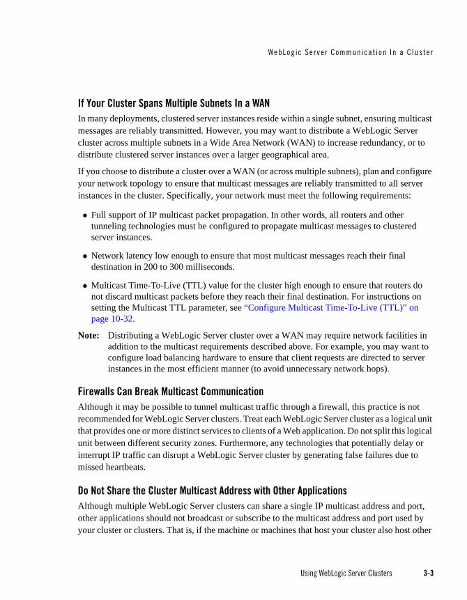
If Your Cluster Spans Multiple Subnets In a WAN In many deployments, clustered server instances reside within a single subnet, ensuring multicast messages are reliably transmitted. However, you may want to distribute a WebLogic Server cluster across multiple subnets in a Wide Area Network (WAN) to increase redundancy, or to distribute clustered server instances over a larger geographical area.
If you choose to distribute a cluster over a WAN (or across multiple subnets), plan and configure your network topology to ensure that multicast messages are reliably transmitted to all server instances in the cluster. Specifically, your network must meet the following requirements:
Full support of IP multicast packet propagation. In other words, all routers and other tunneling technologies must be configured to propagate multicast messages to clustered server instances.
Network latency low enough to ensure that most multicast messages reach their final destination in 200 to 300 milliseconds.
Multicast Time-To-Live (TTL) value for the cluster high enough to ensure that routers do not discard multicast packets before they reach their final destination. For instructions on setting the Multicast TTL parameter, see “Configure Multicast Time-To-Live (TTL)” on page 10-32.
Note: Distributing a WebLogic Server cluster over a WAN may require network facilities in addition to the multicast requirements described above. For example, you may want to configure load balancing hardware to ensure that client requests are directed to server instances in the most efficient manner (to avoid unnecessary network hops).
Firewalls Can Break Multicast CommunicationAlthough it may be possible to tunnel multicast traffic through a firewall, this practice is not recommended for WebLogic Server clusters. Treat each WebLogic Server cluster as a logical unit that provides one or more distinct services to clients of a Web application. Do not split this logical unit between different security zones. Furthermore, any technologies that potentially delay or interrupt IP traffic can disrupt a WebLogic Server cluster by generating false failures due to missed heartbeats.
Do Not Share the Cluster Multicast Address with Other ApplicationsAlthough multiple WebLogic Server clusters can share a single IP multicast address and port, other applications should not broadcast or subscribe to the multicast address and port used by your cluster or clusters. That is, if the machine or machines that host your cluster also host other

3-4 Using WebLogic Server Clusters
applications that use multicast communications, make sure that those applications use a different multicast address and port than the cluster does.
Sharing the cluster multicast address with other applications forces clustered server instances to process unnecessary messages, introducing overhead. Sharing a multicast address may also overload the IP multicast buffer and delay transmission of WebLogic Server heartbeat messages. Such delays can result in a WebLogic Server instance being marked as failed, simply because its heartbeat messages were not received in a timely manner.
For these reasons, assign a dedicated multicast address for use by WebLogic Server clusters, and ensure that the address can support the broadcast traffic of all clusters that use the address.
If Multicast Storms OccurIf server instances in a cluster do not process incoming messages on a timely basis, increased network traffic, including NAK messages and heartbeat re-transmissions, can result. The repeated transmission of multicast packets on a network is referred to as a multicast storm, and can stress the network and attached stations, potentially causing end-stations to hang or fail. Increasing the size of the multicast buffers can improve the rate at which announcements are transmitted and received, and prevent multicast storms. See “Configure Multicast Buffer Size” on page 10-33.
One-to-Many Communication Using UnicastWebLogic Server provides an alternative to using multicast to handle cluster messaging and communications. Unicast configuration is much easier because it does not require cross network configuration that multicast requires. Additionally, it reduces potential network errors that can occur from multicast address conflicts.
Unicast ConfigurationUnicast is configured using ClusterMBean.isUnicastBasedClusterMessagingEnabled(). The default value of this parameter is false. Changes made to this MBean are not dynamic. You must restart your cluster for changes to take effect.
To define a specific channel for unicast communications, you can use the setNetworkChannelForUnicastMessaging(String NetworkChannelName). When unicast is enabled, servers will attempt to use the value defined in this MBean for communications between clusters. If the unicast channel is not explicitly defined, the default network channel is used.

WebLogic Se rve r Communicat ion In a C lus te r
Using WebLogic Server Clusters 3-5
Considerations When Using UnicastThe following considerations apply when using unicast to handle cluster communications:
All members of a cluster must use the same message type. Mixing between multicast and unicast messaging is not allowed.
You must use multicast if you need to support previous version of WebLogic Server within your cluster.
Individual cluster members cannot override the cluster messaging type.
The entire cluster must be shutdown and restarted to message modes.
JMS topics configured for multicasting can access WebLogic clusters configured for Unicast because a JMS topic publishes messages on its own multicast address that is independent of the cluster address. However, the following considerations apply:
– The router hardware configurations that allow unicast clusters may not allow JMS multicast subscribers to work.
– JMS multicast subscribers need to be in a network hardware configuration that allows multicast accessibility.
Notes:
In unicast messaging mode, the default listening port of the server is used if no channel is configured.
Cluster members communicate to the group leader when they need to send a broadcast message which is usually the heartbeat message. When the cluster members detect the failure of a group leader, the next oldest member becomes the group leader.
The frequency of communication in unicast mode is similar to the frequency of sending messages on multicast port.
For more details, see Using Multicasting with WebLogic JMS in Programming WebLogic JMS.
Peer-to-Peer Communication Using IP SocketsIP sockets provide a simple, high-performance mechanism for transferring messages and data between two applications. Clustered WebLogic Server instances use IP sockets for:

3-6 Using WebLogic Server Clusters
Accessing non-clustered objects deployed to another clustered server instance on a different machine.
Replicating HTTP session states and stateful session EJB states between a primary and secondary server instance.
Accessing clustered objects that reside on a remote server instance. (This generally occurs only in a multi-tier cluster architecture, such as the one described in “Recommended Multi-Tier Architecture” on page 9-6.)
Note: The use of IP sockets in WebLogic Server extends beyond the cluster scenario—all RMI communication takes place using sockets, for example, when a remote Java client application accesses a remote object.
Proper socket configuration is crucial to the performance of a WebLogic Server cluster. Two factors determine the efficiency of socket communications in WebLogic Server:
Whether the server instance’s host system uses a native or a pure-Java socket reader implementation.
For systems that use pure-Java socket readers, whether the server instance is configured to use enough socket reader threads.
Pure-Java Versus Native Socket Reader ImplementationsAlthough the pure-Java implementation of socket reader threads is a reliable and portable method of peer-to-peer communication, it does not provide the best performance for heavy-duty socket usage in a WebLogic Server cluster. With pure-Java socket readers, threads must actively poll all opened sockets to determine if they contain data to read. In other words, socket reader threads are always “busy” polling sockets, even if the sockets have no data to read. This unnecessary overhead can reduce performance.
The performance issue is magnified when a server instance has more open sockets than it has socket reader threads—each reader thread must poll more than one open socket. When the socket reader encounters an inactive socket, it waits for a timeout before servicing another. During this timeout period, an active socket may go unread while the socket reader polls inactive sockets, as shown in the following figure.

WebLogic Se rve r Communicat ion In a C lus te r
Using WebLogic Server Clusters 3-7
Figure 3-1 Pure-Java Socket Reader Threads Poll Inactive Sockets
For best socket performance, configure the WebLogic Server host machine to use the native socket reader implementation for your operating system, rather than the pure-Java implementation. Native socket readers use far more efficient techniques to determine if there is data to read on a socket. With a native socket reader implementation, reader threads do not need to poll inactive sockets—they service only active sockets, and they are immediately notified (via an interrupt) when a given socket becomes active.
Note: Applets cannot use native socket reader implementations, and therefore have limited efficiency in socket communication.
For instructions on how to configure the WebLogic Server host machine to use the native socket reader implementation for your operating system, see “Configure Native IP Sockets Readers on Machines that Host Server Instances” on page 10-31.
Configuring Reader Threads for Java Socket ImplementationIf you do use the pure-Java socket reader implementation, you can still improve the performance of socket communication by configuring the proper number of socket reader threads for each server instance. For best performance, the number of socket reader threads in WebLogic Server should equal the potential maximum number of opened sockets. This configuration avoids the situation in which a reader thread must service multiple sockets, and ensures that socket data is read immediately.
1 2 3 4 5 6
Poll ReadPollSocket Reader Thread
Socket
Active Socket

3-8 Using WebLogic Server Clusters
To determine the proper number of reader threads for server instances in your cluster, see the following section, “Determining Potential Socket Usage.”
For instructions on how to configure socket reader threads, see “Set the Number of Reader Threads on Machines that Host Server Instances” on page 10-31.
Determining Potential Socket UsageEach WebLogic Server instance can potentially open a socket for every other server instance in the cluster. However, the actual maximum number of sockets used at a given time depends on the configuration of your cluster. In practice, clustered systems generally do not open a socket for every other server instance, because objects are deployed homogeneously—to each server instance in the cluster.
If your cluster uses in-memory HTTP session state replication, and you deploy objects homogeneously, each server instance potentially opens a maximum of only two sockets, as shown in the following figure.
Figure 3-2 Homogeneous Deployment Minimizes Socket Requirements
JDBC
EJBJSPServlet
JDBC
EJBJSPServlet
JDBC
EJBJSPServlet
JDBC
EJBJSPServlet
D
Potential IP Socket

WebLogic Se rve r Communicat ion In a C lus te r
Using WebLogic Server Clusters 3-9
The two sockets in this example are used to replicate HTTP session states between primary and secondary server instances. Sockets are not required for accessing clustered objects, due to the collocation optimizations that WebLogic Server uses to access those objects. (These optimizations are described in “Optimization for Collocated Objects” on page 5-12.) In this configuration, the default socket reader thread configuration is sufficient.
Deployment of “pinned” services—services that are active on only one server instance at a time—can increase socket usage, because server instances may need to open additional sockets to access the pinned object. (This potential can only be released if a remote server instance actually accesses the pinned object.) The following figure shows the potential effect of deploying a non-clustered RMI object to Server A.
Figure 3-3 Non-Clustered Objects Increase Potential Socket Requirements
JDBC
EJBJSPServlet
JDBC
EJBJSPServlet
JDBC
EJBJSPServlet
JDBC
EJBJSPServlet
A
B
C
D
Potential IP Socket
“Pinned” RMI

3-10 Using WebLogic Server Clusters
In this example, each server instance can potentially open a maximum of three sockets at a given time, to accommodate HTTP session state replication and to access the pinned RMI object on Server A.
Note: Additional sockets may also be required for servlet clusters in a multi-tier cluster architecture, as described in “Configuration Notes for Multi-Tier Architecture” on page 10-34.
Client Communication via SocketsClients of a cluster use the Java implementation of socket reader threads.
WebLogic Server allows you to configure server affinity load balancing algorithms that reduce the number of IP sockets opened by a Java client application. A client accessing multiple objects on a server instance will use a single socket. If an object fails, the client will failover to a server instance to which it already has an open socket, if possible. In older version of WebLogic Server, under some circumstances, a client might open a socket to each server instance in a cluster.
For best performance, configure enough socket reader threads in the Java Virtual Machine (JVM) that runs the client. For instructions, see “Set the Number of Reader Threads on Client Machines” on page 10-32.
Cluster-Wide JNDI Naming ServiceClients of a non-clustered WebLogic Server server instance access objects and services by using a JNDI-compliant naming service. The JNDI naming service contains a list of the public services that the server instance offers, organized in a tree structure. A WebLogic Server instance offers a new service by binding into the JNDI tree a name that represents the service. Clients obtain the service by connecting to the server instance and looking up the bound name of the service.
Server instances in a cluster utilize a cluster-wide JNDI tree. A cluster-wide JNDI tree is similar to a single server instance JNDI tree, insofar as the tree contains a list of available services. In addition to storing the names of local services, however, the cluster-wide JNDI tree stores the services offered by clustered objects (EJBs and RMI classes) from other server instances in the cluster.
Each WebLogic Server instance in a cluster creates and maintains a local copy of the logical cluster-wide JNDI tree. The follow sections describe how the cluster-wide JNDI tree is maintained, and how to avoid naming conflicts that can occur in a clustered environment.
Cluste r -Wide JNDI Naming Serv i ce
Using WebLogic Server Clusters 3-11
WARNING: Do not use the cluster-wide JNDI tree as a persistence or caching mechanism for application data. Although WebLogic Server replicates a clustered server instance’s JNDI entries to other server instances in the cluster, those entries are removed from the cluster if the original instance fails. Also, storing large objects within the JNDI tree can overload multicast or unicast traffic and interfere with the normal operation of a cluster.
How WebLogic Server Creates the Cluster-Wide JNDI TreeEach WebLogic Server in a cluster builds and maintains its own local copy of the cluster-wide JNDI tree, which lists the services offered by all members of the cluster. Creation of a cluster-wide JNDI tree begins with the local JNDI tree bindings of each server instance. As a server instance boots (or as new services are dynamically deployed to a running server instance), the server instance first binds the implementations of those services to the local JNDI tree. The implementation is bound into the JNDI tree only if no other service of the same name exists.
Note: When you start a Managed Server in a cluster, the server instance identifies other running server instances in the cluster by listening for heartbeats, after a warm-up period specified by the MemberWarmupTimeoutSeconds parameter in ClusterMBean. The default warm-up period is 30 seconds.
Once the server instance successfully binds a service into the local JNDI tree, additional steps are performed for clustered objects that use replica-aware stubs. After binding the clustered object’s implementation into the local JNDI tree, the server instance sends the object’s stub to other members of the cluster. Other members of the cluster monitor the multicast or unicast address to detect when remote server instances offer new services.
The following figure shows a snapshot of the JNDI binding process.

3-12 Using WebLogic Server Clusters
Figure 3-4 Server A Binds an Object in its JNDI Tree, then Unicasts Object Availability
In the previous figure, Server A has successfully bound an implementation of clustered Object X into its local JNDI tree. Because Object X is clustered, it offers this service to all other members of the cluster. Server C is still in the process of binding an implementation of Object X.
Other server instances in the cluster listening to the multicast or unicast address note that Server A offers a new service for clustered object, X. These server instances update their local JNDI trees to include the new service.
Updating the local JNDI bindings occurs in one of two ways:
If the clustered service is not yet bound in the local JNDI tree, the server instance binds a new replica-aware stub into the local tree that indicates the availability of Object X on Server A. Servers B and D would update their local JNDI trees in this manner, because the clustered object is not yet deployed on those server instances.
If the server instance already has a binding for the cluster-aware service, it updates its local JNDI tree to indicate that a replica of the service is also available on Server A. Server C would update its JNDI tree in this manner, because it will already have a binding for the clustered Object X.
In this manner, each server instance in the cluster creates its own copy of a cluster-wide JNDI tree. The same process would be used when Server C announces that Object X has been bound into its local JNDI tree. After all broadcast messages are received, each server instance in the
BA
CD
Service offeredon Server A
UnicastIP
A
Object X
C
Object X

Cluste r -Wide JNDI Naming Serv i ce
Using WebLogic Server Clusters 3-13
cluster would have identical local JNDI trees that indicate the availability of the object on Servers A and C, as shown below.
Figure 3-5 Each Server’s JNDI Tree is the Same after Unicast Messages are Received
Note: In an actual cluster, Object X would be deployed homogeneously, and an implementation which can invoke the object would be available on all four server instances.
How JNDI Naming Conflicts OccurSimple JNDI naming conflicts occur when a server instance attempts to bind a non-clustered service that uses the same name as a non-clustered service already bound in the JNDI tree. Cluster-level JNDI conflicts occur when a server instance attempts to bind a clustered object that uses the name of a non-clustered object already bound in the JNDI tree.
WebLogic Server detects simple naming conflicts (of non-clustered services) when those services are bound to the local JNDI tree. Cluster-level JNDI conflicts may occur when new services are advertised over multicast or unicast. For example, if you deploy a pinned RMI object on one server instance in the cluster, you cannot deploy a replica-aware version of the same object on another server instance.
If two server instances in a cluster attempt to bind different clustered objects using the same name, both will succeed in binding the object locally. However, each server instance will refuse
BA
CD UnicastIP
A, C
Object X
A, C
Object X
A, C
Object X
A, C
Object X

3-14 Using WebLogic Server Clusters
to bind the other server instance’s replica-aware stub in to the JNDI tree, due to the JNDI naming conflict. A conflict of this type would remain until one of the two server instances was shut down, or until one of the server instances undeployed the clustered object. This same conflict could also occur if both server instances attempt to deploy a pinned object with the same name.
Deploy Homogeneously to Avoid Cluster-Level JNDI Conflicts To avoid cluster-level JNDI conflicts, you must homogeneously deploy all replica-aware objects to all WebLogic Server instances in a cluster. Having unbalanced deployments across WebLogic Server instances increases the chance of JNDI naming conflicts during startup or redeployment. It can also lead to unbalanced processing loads in the cluster.
If you must pin specific RMI objects or EJBs to individual server instances, do not replicate the object’s bindings across the cluster.
How WebLogic Server Updates the JNDI TreeWhen a clustered object is removed (undeployed from a server instance), updates to the JNDI tree are handled similarly to the updates performed when new services are added. The server instance on which the service was undeployed broadcasts a message indicating that it no longer provides the service. Again, other server instances in the cluster that observe the multicast or unicast message update their local copies of the JNDI tree to indicate that the service is no longer available on the server instance that undeployed the object.
Once the client has obtained a replica-aware stub, the server instances in the cluster may continue adding and removing host servers for the clustered objects. As the information in the JNDI tree changes, the client’s stub may also be updated. Subsequent RMI requests contain update information as necessary to ensure that the client stub remains up-to-date.
Client Interaction with the Cluster-Wide JNDI TreeClients that connect to a WebLogic Server cluster and look up a clustered object obtain a replica-aware stub for the object. This stub contains the list of available server instances that host implementations of the object. The stub also contains the load balancing logic for distributing the load among its host servers.
For more information about replica-aware stubs for EJBs and RMI classes, see “Replication and Failover for EJBs and RMIs” on page 6-25.

Cluste r -Wide JNDI Naming Serv i ce
Using WebLogic Server Clusters 3-15
For a more detailed discussion of how WebLogic JNDI is implemented in a clustered environment and how to make your own objects available to JNDI clients, see “Using WebLogic JNDI in a Clustered Environment” in Programming WebLogic JNDI.

3-16 Using WebLogic Server Clusters

Using WebLogic Server Clusters 4-1
C H A P T E R 4
Understanding Cluster Configuration
This following sections explain how the information that defines the configuration of a cluster is stored and maintained, and the methods you can use to accomplish configuration tasks:
“Cluster Configuration and config.xml” on page 4-1
“Role of the Administration Server” on page 4-2
“How Dynamic Configuration Works” on page 4-4
“Application Deployment for Clustered Configurations” on page 4-4
“Methods of Configuring Clusters” on page 4-8
Note: Much of the information in this section also pertains to the process of configuring a WebLogic domain in which the server instances are not clustered.
Cluster Configuration and config.xmlThe config.xml file is an XML document that describes the configuration of a WebLogic Server domain. config.xml consists of a series of XML elements. The Domain element is the top-level element, and all elements in the Domain descend from the Domain element. The Domain element includes child elements, such as the Server, Cluster, and Application elements. These child elements may have children of their own. For example, the Server element includes the child elements WebServer, SSL and Log. The Application element includes the child elements EJBComponent and WebAppComponent.

4-2 Using WebLogic Server Clusters
Each element has one or more configurable attributes. An attribute defined in config.dtd has a corresponding attribute in the configuration API. For example, the Server element has a ListenPort attribute, and likewise, the weblogic.management.configuration.ServerMBean has a ListenPort attribute. Configurable attributes are readable and writable, that is, ServerMBean has a getListenPort and a setListenPort method.
To learn more about config.xml, see Domain Configuration Files in Understanding Domain Configuration.
Role of the Administration ServerThe Administration Server is the WebLogic Server instance that configures and manages the WebLogic Server instances in its domain.
A domain can include multiple WebLogic Server clusters and non-clustered WebLogic Server instances. Strictly speaking, a domain could consist of only one WebLogic Server instance—however, in that case that sole server instance would be an Administration Server, because each domain must have exactly one Administration Server.
There are a variety of ways to invoke the services of the Administration Server to accomplish configuration tasks, as described in “Methods of Configuring Clusters” on page 4-8. Whichever method is used, the Administration Server for a cluster must be running when you modify the configuration.
When the Administration Server starts, it loads the config.xml for the domain. It looks for config.xml in the directory:
BEA_HOME/user_projects/domains/<domain_name>/config
where domain_name is a domain-specific directory, with the same name as the domain.
Each time the Administration Server starts successfully, a backup configuration file named config.xml.booted is created in the domain directory. In the unlikely event that the config.xml file should be corrupted during the lifetime of the server instance, it is possible to revert to this previous configuration.
The following figure shows a typical production environment that contains an Administration Server and multiple WebLogic Servers instances. When you start the server instances in such a domain, the Administration Server is started first. As each additional server instance is started, it contacts the Administration Server for its configuration information. In this way, the Administration Server operates as the central control entity for the configuration of the entire domain.

Role o f the Admin is t ra t ion Server
Using WebLogic Server Clusters 4-3
Figure 4-1 WebLogic Server Configuration
What Happens if the Administration Server Fails?The failure of an Administration Server for a domain does not affect the operation of Managed Servers in the domain. If an Administration Server for a domain becomes unavailable while the server instances it manages—clustered or otherwise—are up and running, those Managed Servers continue to run. If the domain contains clustered server instances, the load balancing and failover capabilities supported by the domain configuration remain available, even if the Administration Server fails.

4-4 Using WebLogic Server Clusters
Note: If an Administration Server fails because of a hardware or software failure on its host machine, other server instances on the same machine may be similarly affected. However, the failure of an Administration Server itself does not interrupt the operation of Managed Servers in the domain.
For instructions on re-starting an Administration Server, see “Avoiding and Recovering From Server Failure” in Managing Server Startup and Shutdown.
How Dynamic Configuration WorksWebLogic Server allows you to change the configuration attributes of domain resources dynamically—while server instances are running. In most cases you do not need to restart the server instance for your changes to take effect. When an attribute is reconfigured, the new value is immediately reflected in both the current run-time value of the attribute and the persistent value stored in config.xml.
Not all configuration changes are applied dynamically. For example, if you change a Managed Server’s ListenPort value, the new port will not be used until the next time you start the Managed Server. The updated value is stored in config.xml, but the runtime value is not affected.
The Administration Console validates attribute changes, checking for out-of-range errors and data type mismatch errors, and displays an error message for erroneous entries.
Once the Administration Console has been started, if another process captures the listen port assigned to the Administration Server, you should stop the process that captured the port. If you are not able to remove the process that captured the listen port, edit the config.xml file to change the ListenPort value.
Application Deployment for Clustered ConfigurationsThis section is brief introduction to the application deployment process. For more information about deployment, see Deploying WebLogic Server Applications.
For instructions on how to perform common deployment tasks, see “Deploy Applications” on page 10-25.
Deployment MethodsYou can deploy an application to a cluster using following methods:
WebLogic Server Administration Console

Appl i cat ion Dep lo yment f o r C luste red Conf igu rat ions
Using WebLogic Server Clusters 4-5
The Administration Console is a graphical user interface (GUI) to the BEA Administration Service.
weblogic.Deployer
The weblogic.Deployer utility is a Java-based deployment tool that provides a command-line interface to the WebLogic Server deployment API.
WebLogic Scripting Tool
The WebLogic Scripting Tool (WLST) is a new command-line interface that you can use to automate domain configuration tasks, including application deployment configuration and deployment operations.
These deployment tools are discussed in “Overview of Deployment Tools” in Deploying WebLogic Server Applications.
Regardless of the deployment tool you use, when you initiate the deployment process you specify the components to be deployed, and the targets to which they will be deployed—your cluster, or individual server instances within the cluster or domain.
The Administration Server for the domain manages the deployment process, communicating with the Managed Servers in the cluster throughout the process. Each Managed Server downloads components to be deployed, and initiates local deployment tasks. The deployment state is maintained in the relevant MBeans for the component being deployed. For more information, see Deployment Management API.
Note: You must package applications before you deploy them to WebLogic Server. For more information, see the packaging topic in “Deploying the Application” in Developing Applications for WebLogic Server.
Introduction to Two-Phase DeploymentIn WebLogic Server, applications are deployed in two phases. Before starting, WebLogic Server determines the availability of the Managed Servers in the cluster.
First Phase of DeploymentDuring the first phase of deployment, application components are distributed to the target server instances, and the planned deployment is validated to ensure that the application components can be successfully deployed. During this phase, user requests to the application being deployed are not allowed.

4-6 Using WebLogic Server Clusters
Failures encountered during the distribution and validation process will result in the deployment being aborted on all server instances—including those upon which the validation succeeded. Files that have been staged will not be removed; however, container-side changes performed during the preparation will be reverted.
Second Phase of DeploymentAfter the application components have been distributed to targets and validated, they are fully deployed on the target server instances, and the deployed application is made available to clients.
When a failure is encounted during the second phase of deployment, the server starts with one of the following behaviors:
If a failure occurs while deploying to the target server instances, the server instance will start in ADMIN state. See ADMIN State in Managing Server Startup and Shutdown.
If cluster member fails to deploy an application, the application that failed to deploy is made unavailable.
Guidelines for Deploying to a Cluster Ideally, all Managed Servers in a cluster should be running and available during the deployment process. Deploying applications while some members of the cluster are unavailable is not recommended. Before deploying applications to a cluster, ensure, if possible, that all Managed Servers in the cluster are running and reachable by the Administration Server.
Note: If you deploy an application to a Managed Server that is partitioned at the time of deployment—running but not reachable by the Administration Server—problems accessing the Managed Server can occur when that Managed Server rejoins the cluster. During the synchronization period, while other clustered Managed Servers re-establish communications with the previously partitioned server instance, user requests to the deployed applications and attempts to create secondary sessions on that server instance will fail. The risk of this circumstance occurring can be reduced by setting ClusterConstraintsEnabled, as described in Enforcing Cluster Constraints with Two-Phase Deployment in Deploying WebLogic Server Applications.
Cluster membership should not change during the deployment process. After initiating deployment, do not:
add or remove Managed Servers to the target cluster
shut down Managed Servers in the target cluster

Appl i cat ion Dep lo yment f o r C luste red Conf igu rat ions
Using WebLogic Server Clusters 4-7
WebLogic Server Supports “Relaxed Deployment” RulesPrevious versions of WebLogic Server imposed these restrictions on deployment to clusters:
No partial deployment—If one or more of the Managed Servers in the cluster are unavailable, the deployment process is terminated, and an error message is generated, indicating that unreachable Managed Servers should be either restarted or removed from the cluster before attempting deployment.
Pinned services cannot be deployed to multiple Managed Servers in a cluster—If an application is not deployed to the cluster, you can deploy it to one and only one Managed Server in the cluster.
Deployment to a Partial Cluster is AllowedBy default, WebLogic Server allows deployment to a partial cluster. If one or more of the Managed Servers in the cluster are unavailable, the following message may be displayed:
Unable to contact “servername”. Deployment is deferred until “servername”
becomes available.
When the unreachable Managed Server becomes available, deployment to that server instance will be initiated. Until the deployment process is completed, the Managed Server may experience failures related to missing or out-of-date classes.
Deploying to Complete Clusters in WebLogic Server You can ensure that deployment is only performed if all Managed Servers in the cluster are reachable by setting ClusterConstraintsEnabled. When ClusterConstraintsEnabled is set to “true”, a deployment to a cluster succeeds only if all members of the cluster are reachable and all can deploy the specified files. See Enforcing Cluster Constraints with Two-Phase Deployment in Deploying WebLogic Server Applications.
Pinned Services can be Deployed to Multiple Managed Servers.It is possible to target a pinned service to multiple Managed Servers in a cluster. This practice is not recommended. The load-balancing capabilities and scalability of your cluster can be negatively affected by deploying a pinned service to multiple Managed Servers in a cluster. If you target a pinned service to multiple Managed Servers, the following message is printed to the server logs:
Adding server servername of cluster clustername as a target for
module modulename. This module also includes server servername that
belongs to this cluster as one of its other targets. Having multiple

4-8 Using WebLogic Server Clusters
individual servers a cluster as targets instead of having the entire
cluster as the target can result in non-optimal load balancing and
scalability. Hence this is not usually recommended.
Methods of Configuring ClustersThere are several methods for configuring a clusters:
Configuration Wizard
The Configuration Wizard is the recommended tool for creating a new domain or cluster. See “Overview of Creating a New Domain Using the Configuration Wizard” in Creating WebLogic Domains Using the Configuration Wizard. See “Customizing the Environment” for information on creating and configuring a cluster.
WebLogic Server Administration Console
The Administration Console is a graphical user interface (GUI) to the BEA Administration Service. It allows you to perform a variety of domain configuration and monitoring functions.
WebLogic Server Application Programming Interface (API)
You can write a program to modify the configuration attributes, based on the configuration application programming interface (API) provided with WebLogic Server. This method is not recommended for initial cluster implementation.
WebLogic Scripting Tool (WLST)
The WebLogic Scripting Tool (WLST) is a command-line scripting interface that system administrators and operators use to monitor and manage WebLogic Server instances and domains. For more information, see WebLogic Scripting Tool.
Java Management Extensions (JMX)
JMX is the Java EE solution for monitoring and managing resources on a network. BEA WebLogic Server provides a set of MBeans that you can use to configure, monitor, and manage WebLogic Server resources through JMX.
Using WebLogic Server Clusters 5-1
C H A P T E R 5
Load Balancing in a Cluster
This section describes the load balancing support that a WebLogic Server cluster provides for different types of objects, and related planning and configuration considerations for architects and administrators. It contains the following information:
“Load Balancing for Servlets and JSPs” on page 5-1
“Load Balancing for EJBs and RMI Objects” on page 5-4
“Load Balancing for JMS” on page 5-14
“Load Balancing for JDBC Connections” on page 5-16
For information about replication and failover in a cluster, see “Failover and Replication in a Cluster” on page 6-1.
Load Balancing for Servlets and JSPsLoad balancing of servlets and JSPs can be accomplished with the built-in load balancing capabilities of a WebLogic proxy plug-in or with separate load balancing hardware.
Note: In addition to distributing HTTP traffic, external load balancers can distribute initial context requests that come from Java clients over t3 and the default channel. See “Load Balancing for EJBs and RMI Objects” on page 5-4 for a discussion of object-level load balancing in WebLogic Server.
5-2 Using WebLogic Server Clusters
Load Balancing with a Proxy Plug-inThe WebLogic proxy plug-in maintains a list of WebLogic Server instances that host a clustered servlet or JSP, and forwards HTTP requests to those instances on a round-robin basis. This load balancing method is described in “Round Robin Load Balancing” on page 5-4.
The plug-in also provides the logic necessary to locate the replica of a client’s HTTP session state if a WebLogic Server instance should fail.
WebLogic Server supports the following Web servers and associated proxy plug-ins:
WebLogic Server with the HttpClusterServlet
Netscape Enterprise Server with the Netscape (proxy) plug-in
Apache with the Apache Server (proxy) plug-in
Microsoft Internet Information Server with the Microsoft-IIS (proxy) plug-in
For instructions on setting up proxy plug-ins, see “Configure Proxy Plug-Ins” on page 10-14.
How Session Connection and Failover Work with a Proxy Plug-inFor a description of connection and failover for HTTP sessions in a cluster with proxy plug-ins, see “Accessing Clustered Servlets and JSPs Using a Proxy” on page 6-9.
Load Balancing HTTP Sessions with an External Load BalancerClusters that utilize a hardware load balancing solution can use any load balancing algorithm supported by the hardware. These can include advanced load-based balancing strategies that monitor the utilization of individual machines.
Load Balancer Configuration RequirementsIf you choose to use load balancing hardware instead of a proxy plug-in, it must support a compatible passive or active cookie persistence mechanism, and SSL persistence.
Passive Cookie Persistence
Passive cookie persistence enables WebLogic Server to write a cookie containing session parameter information through the load balancer to the client. For information about the session cookie and how a load balancer uses session parameter data to maintain the

Load Balanc ing fo r Se rv le ts and JSPs
Using WebLogic Server Clusters 5-3
relationship between the client and the primary WebLogic Server hosting a HTTP session state, see “Load Balancers and the WebLogic Session Cookie” on page 5-3.
Active Cookie Persistence
Certain active cookie persistence mechanisms can be used with WebLogic Server clusters, provided the load balancer does not modify the WebLogic Server cookie. WebLogic Server clusters do not support active cookie persistence mechanisms that overwrite or modify the WebLogic HTTP session cookie. If the load balancer’s active cookie persistence mechanism works by adding its own cookie to the client session, no additional configuration is required to use the load balancer with a WebLogic Server cluster.
SSL Persistence
When SSL persistence is used, the load balancer performs all encryption and decryption of data between clients and the WebLogic Server cluster. The load balancer then uses the plain text cookie that WebLogic Server inserts on the client to maintain an association between the client and a particular server in the cluster.
Load Balancers and the WebLogic Session CookieA load balancer that uses passive cookie persistence can use a string in the WebLogic session cookie to associate a client with the server hosting its primary HTTP session state. The string uniquely identifies a server instance in the cluster. You must configure the load balancer with the offset and length of the string constant. The correct values for the offset and length depend on the format of the session cookie.
The format of a session cookie is:
sessionid!primary_server_id!secondary_server_id
where:
sessionid is a randomly generated identifier of the HTTP session. The length of the value is configured by the IDLength parameter in the <session-descriptor> element in the weblogic.xml file for an application. By default, the sessionid length is 52 bytes.
primary_server_id and secondary_server_id are 10 character identifiers of the primary and secondary hosts for the session.
Note: For sessions using non-replicated memory, cookie, JDBC, or file-based session persistence, the secondary_server_id is not present. For sessions that use in-memory replication, if the secondary session does not exist, the secondary_server_id is “NONE”.

5-4 Using WebLogic Server Clusters
For general instructions on configuring load balancers, see “Configuring Load Balancers that Support Passive Cookie Persistence” on page 10-13. Instructions for configuring BIG-IP, see Configuring BIG-IP™ Hardware with Clusters.
Related Programming Considerations For programming constraints and recommendations for clustered servlets and JSPs, see “Programming Considerations for Clustered Servlets and JSPs” on page 6-5.
How Session Connection and Failover Works with a Load BalancerFor a description of connection and failover for HTTP sessions in a cluster with load balancing hardware, see “Accessing Clustered Servlets and JSPs with Load Balancing Hardware” on page 6-11.
Load Balancing for EJBs and RMI ObjectsThis section describes WebLogic Server load balancing algorithms for EJBs and RMI objects.
The load balancing algorithm for an object is maintained in the replica-aware stub obtained for a clustered object.
By default, a WebLogic Server cluster uses round-robin load balancing, described in “Round Robin Load Balancing” on page 5-4. You can configure a different default load balancing method for the cluster by using the Administration Console to set weblogic.cluster.defaultLoadAlgorithm. For instructions, see “Configure Load Balancing Method for EJBs and RMIs” on page 10-12. You can also specify the load balancing algorithm for a specific RMI object using the -loadAlgorithm option in rmic, or with the home-load-algorithm or stateless-bean-load-algorithm in an EJB’s deployment descriptor. A load balancing algorithm that you configure for an object overrides the default load balancing algorithm for the cluster.
In addition to the standard load balancing algorithms, WebLogic Server supports custom parameter-based routing. For more information, see “Parameter-Based Routing for Clustered Objects” on page 5-12.
Round Robin Load Balancing WebLogic Server uses the round-robin algorithm as the default load balancing strategy for clustered object stubs when no algorithm is specified. This algorithm is supported for RMI objects and EJBs. It is also the method used by WebLogic proxy plug-ins.
Load Ba lanc ing fo r E JBs and RMI Ob jec ts
Using WebLogic Server Clusters 5-5
The round-robin algorithm cycles through a list of WebLogic Server instances in order. For clustered objects, the server list consists of WebLogic Server instances that host the clustered object. For proxy plug-ins, the list consists of all WebLogic Server instances that host the clustered servlet or JSP.
The advantages of the round-robin algorithm are that it is simple, cheap and very predictable. The primary disadvantage is that there is some chance of convoying. Convoying occurs when one server is significantly slower than the others. Because replica-aware stubs or proxy plug-ins access the servers in the same order, a slow server can cause requests to “synchronize” on the server, then follow other servers in order for future requests.
Note: WebLogic Server does not always load balance an object’s method calls. For more information, see “Optimization for Collocated Objects” on page 5-12.
Weight-Based Load Balancing This algorithm applies only to EJB and RMI object clustering.
Weight-based load balancing improves on the round-robin algorithm by taking into account a pre-assigned weight for each server. You can use the Server -> Configuration -> Cluster tab in the Administration Console to assign each server in the cluster a numerical weight between 1 and 100, in the Cluster Weight field. This value determines what proportion of the load the server will bear relative to other servers. If all servers have the same weight, they will each bear an equal proportion of the load. If one server has weight 50 and all other servers have weight 100, the 50-weight server will bear half as much as any other server. This algorithm makes it possible to apply the advantages of the round-robin algorithm to clusters that are not homogeneous.
If you use the weight-based algorithm, carefully determine the relative weights to assign to each server instance. Factors to consider include:
The processing capacity of the server’s hardware in relationship to other servers (for example, the number and performance of CPUs dedicated to WebLogic Server).
The number of non-clustered (“pinned”) objects each server hosts.
If you change the specified weight of a server and reboot it, the new weighting information is propagated throughout the cluster via the replica-aware stubs. For related information see “Cluster-Wide JNDI Naming Service” on page 3-10.

5-6 Using WebLogic Server Clusters
Notes: WebLogic Server does not always load balance an object’s method calls. For more information, see “Optimization for Collocated Objects” on page 5-12.
In this version of WebLogic Server, weight-based load balancing is not supported for objects that communicate using the RMI/IIOP protocol.
Random Load BalancingThe random method of load balancing applies only to EJB and RMI object clustering.
In random load balancing, requests are routed to servers at random. Random load balancing is recommended only for homogeneous cluster deployments, where each server instance runs on a similarly configured machine. A random allocation of requests does not allow for differences in processing power among the machines upon which server instances run. If a machine hosting servers in a cluster has significantly less processing power than other machines in the cluster, random load balancing will give the less powerful machine as many requests as it gives more powerful machines.
Random load balancing distributes requests evenly across server instances in the cluster, increasingly so as the cumulative number of requests increases. Over a small number of requests the load may not be balanced exactly evenly.
Disadvantages of random load balancing include the slight processing overhead incurred by generating a random number for each request, and the possibility that the load may not be evenly balanced over a small number of requests.
Note: WebLogic Server does not always load balance an object’s method calls. For more information, see “Optimization for Collocated Objects” on page 5-12.
Server Affinity Load Balancing AlgorithmsWebLogic Server provides three load balancing algorithms for RMI objects that provide server affinity. Server affinity turns off load balancing for external client connections: instead, the client considers its existing connections to WebLogic server instances when choosing the server instance on which to access an object. If an object is configured for server affinity, the client-side stub attempts to choose a server instance to which it is already connected, and continues to use the same server instance for method calls. All stubs on that client attempt to use that server instance. If the server instance becomes unavailable, the stubs fail over, if possible, to a server instance to which the client is already connected.
The purpose of server affinity is to minimize the number IP sockets opened between external Java clients and server instances in a cluster. WebLogic Server accomplishes this by causing method

Load Ba lanc ing fo r E JBs and RMI Ob jec ts
Using WebLogic Server Clusters 5-7
calls on objects to “stick” to an existing connection, instead of being load balanced among the available server instances. With server affinity algorithms, the less costly server-to-server connections are still load-balanced according to the configured load balancing algorithm—load balancing is disabled only for external client connections.
Server affinity is used in combination with one of the standard load balancing methods: round-robin, weight-based, or random:
round-robin-affinity—server affinity governs connections between external Java clients and server instances; round robin load balancing is used for connections between server instances.
weight-based-affinity—server affinity governs connections between external Java clients and server instances; weight-based load balancing is used for connections between server instances.
random-affinity—server affinity governs connections between external Java clients and server instances; random load balancing is used for connections between server instances.
Server Affinity and Initial ContextA client can request an initial context from a particular server instance in the cluster, or from the cluster by specifying the cluster address in the URL. The connection process varies, depending on how the context is obtained:
If the initial context is requested from a specific Managed Server, the context is obtained using a new connection to the specified server instance.
If the initial context is requested from a the cluster, by default, context requests are load balanced on a round-robin basis among the clustered server instances. To reuse an existing connection between a particular JVM and the cluster, set ENABLE_SERVER_AFFINITY to true in the hashtable of weblogic.jndi.WLContext properties you specify when obtaining context. (If a connection is not available, a new connection is created.) ENABLE_SERVER_AFFINITY is only supported when the context is requested from the cluster address.
Server Affinity and IIOP Client Authentication Using CSIv2If you use WebLogic Server’s Common Secure Interoperability (CSIv2) functionality to support stateful interactions with WebLogic Server’s Java EE Application Client (“thin client”), you must use an affinity-based load balancing algorithm to ensure that method calls stick to a server instance. Otherwise, all remote calls will be authenticated. To prevent redundant authentication

5-8 Using WebLogic Server Clusters
of stateful CSIv2 clients, use one of the load balancing algorithms described in “Round-Robin Affinity, Weight-Based Affinity, and Random-Affinity” on page 5-8.
Round-Robin Affinity, Weight-Based Affinity, and Random-AffinityWebLogic Server has three load balancing algorithms that provide server affinity:
round-robin-affinity
weight-based-affinity
random-affinity
Server affinity is supported for all types of RMI objects including JMS objects, all EJB home interfaces, and stateless EJB remote interfaces.
The server affinity algorithms consider existing connections between an external Java client and server instances in balancing the client load among WebLogic server instances. Server affinity:
turns off load balancing between external Java clients and server instances
causes method calls from an external Java client to stick to a server instance to which the client has an open connection, assuming that the connection supports the necessary protocol and QOS
in the case of failure, causes the client to failover to a server instance to which it has an open connection, assuming that the connection supports the necessary protocol and QOS
does not affect the load balancing performed for server-to-server connections
Server Affinity ExamplesThe following examples illustrate the effect of server affinity under a variety of circumstances. In each example, the objects deployed are configured for round-robin-affinity.
Example 1—Context from clusterIn this example, the client obtains context from the cluster. Lookups on the context and object calls stick to a single connection. Requests for new initial context are load balanced on a round-robin basis.

Load Ba lanc ing fo r E JBs and RMI Ob jec ts
Using WebLogic Server Clusters 5-9
Figure 5-1 Client Obtains Context From the Cluster
1. Client requests a new initial context from the cluster (Provider_URL=clusteraddress) and obtains the context from MS1.
2. Client does a lookup on the context for Object A. The lookup goes to MS1.
3. Client issues a call to Object A. The call goes to MS1, to which the client is already connected. Additional method calls to Object A stick to MS1.
4. Client requests a new initial context from the cluster (Provider_URL=clusteraddress) and obtains the context from MS2.
5. Client does a lookup on the context for Object B. The call goes to MS2, to which the client is already connected. Additional method calls to Object B stick to MS2.

5-10 Using WebLogic Server Clusters
Example 2—Server Affinity and FailoverThis example illustrates the effect that server affinity has on object failover. When a Managed Server goes down, the client fails over to another Managed Server to which it has a connection.
Figure 5-2 Server Affinity and Failover
1. Client requests new initial context from MS1.
2. Client does a lookup on the context for Object A. The lookup goes to MS1.
3. Client makes a call to Object A. The call goes to MS1, to which the client is already connected. Additional calls to Object A stick to MS1.
4. The client obtains a stub for Object C, which is pinned to MS3. The client opens a connection to MS3.

Load Ba lanc ing fo r E JBs and RMI Ob jec ts
Using WebLogic Server Clusters 5-11
5. MS1 fails.
6. Client makes a call to Object A.The client no longer has a connection to MS1. Because the client is connected to MS3, it fails over to a replica of Object A on MS3.
Example 3—Server affinity and server-to-server connectionsThis example illustrates the fact that server affinity does not affect the connections between server instances.
Figure 5-3 Server Affinity and Server-to-Server Connections
1. A JSP on MS4 obtains a stub for Object B.
2. The JSP selects a replica on MS1. For each method call, the JSP cycles through the Managed Servers upon which Object B is available, on a round-robin basis.
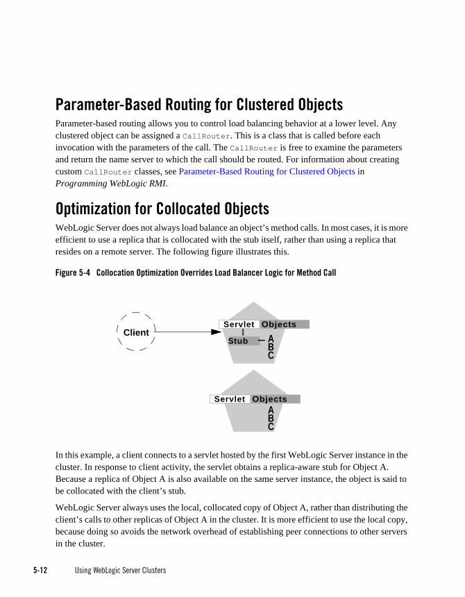
5-12 Using WebLogic Server Clusters
Parameter-Based Routing for Clustered ObjectsParameter-based routing allows you to control load balancing behavior at a lower level. Any clustered object can be assigned a CallRouter. This is a class that is called before each invocation with the parameters of the call. The CallRouter is free to examine the parameters and return the name server to which the call should be routed. For information about creating custom CallRouter classes, see Parameter-Based Routing for Clustered Objects in Programming WebLogic RMI.
Optimization for Collocated ObjectsWebLogic Server does not always load balance an object’s method calls. In most cases, it is more efficient to use a replica that is collocated with the stub itself, rather than using a replica that resides on a remote server. The following figure illustrates this.
Figure 5-4 Collocation Optimization Overrides Load Balancer Logic for Method Call
In this example, a client connects to a servlet hosted by the first WebLogic Server instance in the cluster. In response to client activity, the servlet obtains a replica-aware stub for Object A. Because a replica of Object A is also available on the same server instance, the object is said to be collocated with the client’s stub.
WebLogic Server always uses the local, collocated copy of Object A, rather than distributing the client’s calls to other replicas of Object A in the cluster. It is more efficient to use the local copy, because doing so avoids the network overhead of establishing peer connections to other servers in the cluster.
ObjectsClient A
BC
Servlet
Stub
ABC
Servlet Objects

Load Ba lanc ing fo r E JBs and RMI Ob jec ts
Using WebLogic Server Clusters 5-13
This optimization is often overlooked when planning WebLogic Server clusters. The collocation optimization is also frequently confusing for administrators or developers who expect or require load balancing on each method call. If your Web application is deployed to a single cluster, the collocation optimization overrides any load balancing logic inherent in the replica-aware stub.
If you require load balancing on each method call to a clustered object, see “Recommended Multi-Tier Architecture” on page 9-6 for information about how to plan your WebLogic Server cluster accordingly.
Transactional CollocationAs an extension to the basic collocation strategy, WebLogic Server attempts to use collocated clustered objects that are enlisted as part of the same transaction. When a client creates a UserTransaction object, WebLogic Server attempts to use object replicas that are collocated with the transaction. This optimization is depicted in the figure below.
Figure 5-5 Collocation Optimization Extends to Other Objects in Transaction
In this example, a client attaches to he first WebLogic Server instance in the cluster and obtains a UserTransaction object. After beginning a new transaction, the client looks up Objects A and
Database
ObjectsClientABC
Servlet
ABC
Servlet
Servlet
Objects
ObjectsABC
TransactionUser

5-14 Using WebLogic Server Clusters
B to do the work of the transaction. In this situation WebLogic Server always attempts to use replicas of A and B that reside on the same server as the UserTransaction object, regardless of the load balancing strategies in the stubs for A and B.
This transactional collocation strategy is even more important than the basic optimization described in “Optimization for Collocated Objects” on page 5-12. If remote replicas of A and B were used, added network overhead would be incurred for the duration of the transaction, because the peer connections for A and B would be locked until the transaction committed. Furthermore, WebLogic Server would need to employ a multi-tiered JDBC connection to commit the transaction, incurring additional network overhead.
By using collocating clustered objects during a transaction, WebLogic Server reduces the network load for accessing the individual objects. The server also can make use of a single-tiered JDBC connection, rather than a multi-tiered connection, to do the work of the transaction.
Load Balancing for JMSWebLogic Server JMS supports server affinity for distributed JMS destinations and client connections.
By default, a WebLogic Server cluster uses the round-robin method to load balance objects. To use a load balancing algorithm that provides server affinity for JMS objects, you must configure the desired method for the cluster as a whole. You can configure the load balancing algorithm by using the Administration Console to set weblogic.cluster.defaultLoadAlgorithm. For instructions, see “Configure Load Balancing Method for EJBs and RMIs” on page 10-12.
Note: To provide persistent store for failover of JMS and JTA pinned services, you may consider using high-availability clustering software such as VERITAS™ Cluster Server, which provides an integrated, out-of-the-box solution for BEA WebLogic Server-based applications. Some other recommended high-availability software solutions include SunCluster, IBM HACMP, or the equivalent.
Server Affinity for Distributed JMS Destinations Server affinity is supported for JMS applications that use the distributed destination feature; this feature is not supported for standalone destinations. If you configure server affinity for JMS connection factories, a server instance that is load balancing consumers or producers across multiple members of a distributed destination will first attempt to load balance across any destination members that are also running on the same server instance.

Load Ba lanc ing fo r JMS
Using WebLogic Server Clusters 5-15
For detailed information on how the JMS connection factory’s Server Affinity Enabled option affects the load balancing preferences for distributed destination members, see “How Distributed Destination Load Balancing Is Affected When Using the Server Affinity Enabled Attribute” in Programming WebLogic JMS.
Initial Context Affinity and Server Affinity for Client Connections A system administrator can establish load balancing of JMS destinations across multiple servers in a cluster by configuring multiple JMS servers and using targets to assign them to the defined WebLogic Servers. Each JMS server is deployed on exactly one WebLogic Server and handles requests for a set of destinations. During the configuration phase, the system administrator enables load balancing by specifying targets for JMS servers. For instructions on setting up targets, see “Configure Migratable Targets for Pinned Services” on page 10-23. For instructions on deploying a JMS server to a migratable target, see “Deploying, Activating, and Migrating Migratable Services” on page 10-27.
A system administrator can establish cluster-wide, transparent access to destinations from any server in the cluster by configuring multiple connection factories and using targets to assign them to WebLogic Servers. Each connection factory can be deployed on multiple WebLogic Servers. Connection factories are described in more detail in “Connection Factory” in Programming WebLogic JMS.
The application uses the Java Naming and Directory Interface (JNDI) to look up a connection factory and create a connection to establish communication with a JMS server. Each JMS server handles requests for a set of destinations. Requests for destinations not handled by a JMS server are forwarded to the appropriate server.
WebLogic Server provides server affinity for client connections. If an application has a connection to a given server instance, JMS will attempt to establish new JMS connections to the same server instance.
When creating a connection, JMS will try first to achieve initial context affinity. It will attempt to connect to the same server or servers to which a client connected for its initial context, assuming that the server instance is configured for that connection factory. For example, if the connection factory is configured for servers A and B, but the client has an InitialContext on server C, then the connection factory will not establish the new connection with A, but will choose between servers B and C.
If a connection factory cannot achieve initial context affinity, it will try to provide affinity to a server to which the client is already connected. For instance, assume the client has an

5-16 Using WebLogic Server Clusters
InitialContext on server A and some other type of connection to server B. If the client then uses a connection factory configured for servers B and C it will not achieve initial context affinity. The connection factory will instead attempt to achieve server affinity by trying to create a connection to server B, to which it already has a connection, rather than server C.
If a connection factory cannot provide either initial context affinity or server affinity, then the connection factory is free to make a connection wherever possible. For instance, assume a client has an initial context on server A, no other connections and a connection factory configured for servers B and C. The connection factory is unable to provide any affinity and is free to attempt new connections to either server B or C.
Note: In the last case, if the client attempts to make a second connection using the same connection factory, it will go to the same server as it did on the first attempt. That is, if it chose server B for the first connection, when the second connection is made, the client will have a connection to server B and the server affinity rule will be enforced.
Load Balancing for JDBC ConnectionsLoad balancing of JDBC connection requires the use of a multi data source configured for load balancing. Load balancing support is an option you can choose when configuring a multi data source.
A load balancing multi data source provides the high available behavior described in “Failover and JDBC Connections” on page 6-32, and in addition, balances the load among the data sources in the multi data source. A multi data source has an ordered list of data sources it contains. If you do not configure the multi data source for load balancing, it always attempts to obtain a connection from the first data source in the list. In a load-balancing multi data source, the data sources it contains are accessed using a round-robin scheme. In each successive client request for a multi data source connection, the list is rotated so the first pool tapped cycles around the list.
For instructions on clustering JDBC objects, see “Configure Clustered JDBC” on page 10-24.

Using WebLogic Server Clusters 6-1
C H A P T E R 6
Failover and Replication in a Cluster
In order for a cluster to provide high availability it must be able to recover from service failures. The following sections describe how WebLogic Server detect failures in a cluster, and provides an overview of how failover is accomplished for different types of objects:
“How WebLogic Server Detects Failures” on page 6-1
“Replication and Failover for Servlets and JSPs” on page 6-2
“Replication and Failover for EJBs and RMIs” on page 6-25
“Failover and JDBC Connections” on page 6-32
This chapter focuses on failover and replication at the application level. WebLogic Server also supports automatic migration of server instances and services after failure. For more information, see Chapter 7, “Whole Server Migration”.
How WebLogic Server Detects FailuresWebLogic Server instances in a cluster detect failures of their peer server instances by monitoring:
Socket connections to a peer server
Regular server heartbeat messages

6-2 Using WebLogic Server Clusters
Failure Detection Using IP SocketsWebLogic Server instances monitor the use of IP sockets between peer server instances as an immediate method of detecting failures. If a server connects to one of its peers in a cluster and begins transmitting data over a socket, an unexpected closure of that socket causes the peer server to be marked as “failed,” and its associated services are removed from the JNDI naming tree.
The WebLogic Server “Heartbeat”If clustered server instances do not have opened sockets for peer-to-peer communication, failed servers may also be detected via the WebLogic Server heartbeat. All server instances in a cluster use multicast or unicast to broadcast regular server heartbeat messages to other members of the cluster.
Note: For backward compatibility with previous versions, WebLogic Server also allows you to use multicast for communications between clusters.
Each heartbeat message contains data that uniquely identifies the server that sends the message. Servers broadcast their heartbeat messages at regular intervals of 10 seconds. In turn, each server in a cluster monitors the multicast or unicast address to ensure that all peer servers’ heartbeat messages are being sent.
Note: For backward compatibility with previous versions, WebLogic Server also allows you to use multicast for communications between clusters.
If a server monitoring the multicast or unicast address misses three heartbeats from a peer server (i.e., if it does not receive a heartbeat from the server for 30 seconds or longer), the monitoring server marks the peer server as “failed.” It then updates its local JNDI tree, if necessary, to retract the services that were hosted on the failed server.
In this way, servers can detect failures even if they have no sockets open for peer-to-peer communication.
Note: For more information about how WebLogic Server uses IP sockets and either multicast or unicast communications see “WebLogic Server Communication In a Cluster” on page 3-1.
Replication and Failover for Servlets and JSPs To support automatic replication and failover for servlets and JSPs within a cluster, Weblogic Server supports two mechanisms for preserving HTTP session state:
hardware load balancers

Repl i cat i on and Fa i l ove r f o r Se rv le ts and JSPs
Using WebLogic Server Clusters 6-3
For clusters that use a supported hardware load balancing solution, the load balancing hardware simply redirects client requests to any available server in the WebLogic Server cluster. The cluster itself obtains the replica of the client’s HTTP session state from a secondary server in the cluster.
proxy plug-ins
In clusters that utilize Web servers with WebLogic proxy plug-ins, the proxy plug-in handles failover transparently to the client. If a server fails, the plug-in locates the replicated HTTP session state on a secondary server and redirects the client’s request accordingly.
This section covers the following topics:
“HTTP Session State Replication” on page 6-3
“Accessing Clustered Servlets and JSPs Using a Proxy” on page 6-9
“Accessing Clustered Servlets and JSPs with Load Balancing Hardware” on page 6-11
“Session State Replication Across Clusters in a MAN/WAN” on page 6-14
HTTP Session State ReplicationWeblogic Server uses two methods for replicating HTTP session state across clusters:
in-memory replication
Using in-memory replication, WebLogic Server copies a session state from one server instance to another. The primary server creates a primary session state on the server to which the client first connects, and a secondary replica on another WebLogic Server instance in the cluster. The replica is kept up-to-date so that it may be used if the server that hosts the servlet fails.
JDBC-based persistence
In JDBC-based persistence, WebLogic Server maintains the HTTP session state of a servlet or JSP using file-based or JDBC-based persistence. For more information on these persistence mechanisms, see “Configuring Session Persistence” in Programming WebLogic HTTP Servlets.
JDBC-based persistence is also used for HTTP session state replication within a Wide Area Network (WAN). For more information, see “WAN HTTP Session State Replication” on page 6-22.

6-4 Using WebLogic Server Clusters
Note: WebApps which have persistent store type set to replicated or replicated_if_clustered will have to be targetted to the cluster or all the nodes of that cluster. If its targetted to only some nodes in the cluster then the webapp will not be deployed. In memory replication requires that webapps be deployed homogeneously on all the nodes in a cluster.
The following section describe session state replication using in-memory replication.
Requirements for HTTP Session State ReplicationTo utilize in-memory replication for HTTP session states, you must access the WebLogic Server cluster using either a collection of Web servers with identically configured WebLogic proxy plug-ins, or load balancing hardware.
Supported Server and Proxy SoftwareThe WebLogic proxy plug-in maintains a list of WebLogic Server instances that host a clustered servlet or JSP, and forwards HTTP requests to those instances using a round-robin strategy. The plug-in also provides the logic necessary to locate the replica of a client’s HTTP session state if a WebLogic Server instance should fail.
In-memory replication for HTTP session states is supported by the following Web servers and proxy software:
WebLogic Server with the HttpClusterServlet
Netscape Enterprise Server with the Netscape (proxy) plug-in
Apache with the Apache Server (proxy) plug-in
Microsoft Internet Information Server with the Microsoft-IIS (proxy) plug-in
For instructions on setting up proxy plug-ins, see “Configure Proxy Plug-Ins” on page 10-14.
Load Balancer RequirementsIf you choose to use load balancing hardware instead of a proxy plug-in, it must support a compatible passive or active cookie persistence mechanism, and SSL persistence. For details on these requirements, see “Load Balancer Configuration Requirements” on page 5-2. For instructions on setting up a load balancer, see “Configuring Load Balancers that Support Passive Cookie Persistence” on page 10-13.
Repl i cat i on and Fa i l ove r f o r Se rv le ts and JSPs
Using WebLogic Server Clusters 6-5
Programming Considerations for Clustered Servlets and JSPsThis section highlights key programming constraints and recommendations for servlets and JSPs that you will deploy in a clustered environment.
Session Data Must Be Serializable
To support in-memory replication of HTTP session states, all servlet and JSP session data must be serializable.
Note: Serialization is the process of converting a complex data structure, such as a parallel arrangement of data (in which a number of bits are transmitted at a time along parallel channels) into a serial form (in which one bit at a time is transmitted); a serial interface provides this conversion to enable data transmission.
Every field in an object must be serializable or transient in order for the object to be considered serializable. If the servlet or JSP uses a combination of serializable and non-serializable objects, WebLogic Server does not replicate the session state of the non-serializable objects.
Use setAttribute to Change Session State
In an HTTP servlet that implements javax.servlet.http.HttpSession, use HttpSession.setAttribute (which replaces the deprecated putValue) to change attributes in a session object. If you set attributes in a session object with setAttribute, the object and its attributes are replicated in a cluster using in-memory replication. If you use other set methods to change objects within a session, WebLogic Server does not replicate those changes. Every time a change is made to an object that is in the session, setAttribute() should be called to update that object across the cluster.
Likewise, use removeAttribute (which, in turn, replaces the deprecated removeValue) to remove an attribute from a session object.
Note: Use of the deprecated putValue and removeValue methods will also cause session attributes to be replicated.
Consider Serialization Overhead
Serializing session data introduces some overhead for replicating the session state. The overhead increases as the size of serialized objects grows. If you plan to create very large objects in the session, test the performance of your servlets to ensure that performance is acceptable.
Control Frame Access to Session Data

6-6 Using WebLogic Server Clusters
If you are designing a Web application that utilizes multiple frames, keep in mind that there is no synchronization of requests made by frames in a given frameset. For example, it is possible for multiple frames in a frameset to create multiple sessions on behalf of the client application, even though the client should logically create only a single session.
In a clustered environment, poor coordination of frame requests can cause unexpected application behavior. For example, multiple frame requests can “reset” the application’s association with a clustered instance, because the proxy plug-in treats each request independently. It is also possible for an application to corrupt session data by modifying the same session attribute via multiple frames in a frameset.
To avoid unexpected application behavior, carefully plan how you access session data with frames. You can apply one of the following general rules to avoid common problems:
– In a given frameset, ensure that only one frame creates and modifies session data.
– Always create the session in a frame of the first frameset your application uses (for example, create the session in the first HTML page that is visited). After the session has been created, access the session data only in framesets other than the first frameset.
Using Replication GroupsBy default, WebLogic Server attempts to create session state replicas on a different machine than the one that hosts the primary session state. You can further control where secondary states are placed using replication groups. A replication group is a preferred list of clustered servers to be used for storing session state replicas.
Using the WebLogic Server Console, you can define unique machine names that will host individual server instances. These machine names can be associated with new WebLogic Server instances to identify where the servers reside in your system.
Machine names are generally used to indicate servers that run on the same machine. For example, you would assign the same machine name to all server instances that run on the same machine, or the same server hardware.
If you do not run multiple WebLogic Server instances on a single machine, you do not need to specify WebLogic Server machine names. Servers without a machine name are treated as though they reside on separate machines. For detailed instructions on setting machine names, see “Configure Machine Names” on page 10-34.
When you configure a clustered server instance, you can assign the server to a replication group, and a preferred secondary replication group for hosting replicas of the primary HTTP session states created on the server.

Repl i cat i on and Fa i l ove r f o r Se rv le ts and JSPs
Using WebLogic Server Clusters 6-7
When a client attaches to a server in the cluster and creates a primary session state, the server hosting the primary state ranks other servers in the cluster to determine which server should host the secondary. Server ranks are assigned using a combination of the server’s location (whether or not it resides on the same machine as the primary server) and its participation in the primary server’s preferred replication group. The following table shows the relative ranking of servers in a cluster.
Using these rules, the primary WebLogic Server ranks other members of the cluster and chooses the highest-ranked server to host the secondary session state. For example, the following figure shows replication groups configured for different geographic locations.
Table 6-1 Ranking Server Instances for Session Replication
Server Rank Server Resides on a Different Machine
Server is a Member of Preferred Replication Group
1 Yes Yes
2 No Yes
3 Yes No
4 No No
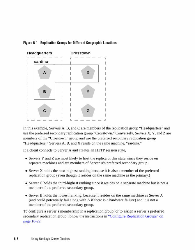
6-8 Using WebLogic Server Clusters
Figure 6-1 Replication Groups for Different Geographic Locations
In this example, Servers A, B, and C are members of the replication group “Headquarters” and use the preferred secondary replication group “Crosstown.” Conversely, Servers X, Y, and Z are members of the “Crosstown” group and use the preferred secondary replication group “Headquarters.” Servers A, B, and X reside on the same machine, “sardina.”
If a client connects to Server A and creates an HTTP session state,
Servers Y and Z are most likely to host the replica of this state, since they reside on separate machines and are members of Server A’s preferred secondary group.
Server X holds the next-highest ranking because it is also a member of the preferred replication group (even though it resides on the same machine as the primary.)
Server C holds the third-highest ranking since it resides on a separate machine but is not a member of the preferred secondary group.
Server B holds the lowest ranking, because it resides on the same machine as Server A (and could potentially fail along with A if there is a hardware failure) and it is not a member of the preferred secondary group.
To configure a server’s membership in a replication group, or to assign a server’s preferred secondary replication group, follow the instructions in “Configure Replication Groups” on page 10-22.
X
Y
Z
Crosstown
B
sardina
Headquarters
C
A
B

Repl i cat i on and Fa i l ove r f o r Se rv le ts and JSPs
Using WebLogic Server Clusters 6-9
Accessing Clustered Servlets and JSPs Using a ProxyThis section describes the connection and failover processes for requests that are proxied to clustered servlets and JSPs. For instructions on setting up proxy plug-ins, see “Configure Proxy Plug-Ins” on page 10-14.
The following figure depicts a client accessing a servlet hosted in a cluster. This example uses a single WebLogic Server to serve static HTTP requests only; all servlet requests are forwarded to the WebLogic Server cluster via the HttpClusterServlet.
Figure 6-2 Accessing Servlets and JSPs using a Proxy
Note: The discussion that follows also applies if you use a third-party Web server and WebLogic proxy plug-in, rather than WebLogic Server and the HttpClusterServlet.
Proxy Connection ProcedureWhen the HTTP client requests the servlet, HttpClusterServlet proxies the request to the WebLogic Server cluster. HttpClusterServlet maintains the list of all servers in the cluster, and the load balancing logic to use when accessing the cluster. In the above example,
Primary State
Servlet
Servlet
WebLogic ServerCluster
Client
Servlet
A
B
C
Secondary
HttpClusterServlet
HTTP Server
Cookie
Primary: ASecondary: B
State

6-10 Using WebLogic Server Clusters
HttpClusterServlet routes the client request to the servlet hosted on WebLogic Server A. WebLogic Server A becomes the primary server hosting the client’s servlet session.
To provide failover services for the servlet, the primary server replicates the client’s servlet session state to a secondary WebLogic Server in the cluster. This ensures that a replica of the session state exists even if the primary server fails (for example, due to a network failure). In the example above, Server B is selected as the secondary.
The servlet page is returned to the client through the HttpClusterServlet, and the client browser is instructed to write a cookie that lists the primary and secondary locations of the servlet session state. If the client browser does not support cookies, WebLogic Server can use URL rewriting instead.
Using URL Rewriting to Track Session ReplicasIn its default configuration, WebLogic Server uses client-side cookies to keep track of the primary and secondary server that host the client’s servlet session state. If client browsers have disabled cookie usage, WebLogic Server can also keep track of primary and secondary servers using URL rewriting. With URL rewriting, both locations of the client session state are embedded into the URLs passed between the client and proxy server. To support this feature, you must ensure that URL rewriting is enabled on the WebLogic Server cluster. For instructions on how to enable URL rewriting, see “Using URL Rewriting”, in Assembling and Configuring Web Applications.
Proxy Failover ProcedureShould the primary server fail, HttpClusterServlet uses the client’s cookie information to determine the location of the secondary WebLogic Server that hosts the replica of the session state. HttpClusterServlet automatically redirects the client’s next HTTP request to the secondary server, and failover is transparent to the client.
After the failure, WebLogic Server B becomes the primary server hosting the servlet session state, and a new secondary is created (Server C in the previous example). In the HTTP response, the proxy updates the client’s cookie to reflect the new primary and secondary servers, to account for the possibility of subsequent failovers.
Note: Now WebLogic proxy plug-ins randomly pick up a secondary server after the failover.
In a two-server cluster, the client would transparently fail over to the server hosting the secondary session state. However, replication of the client’s session state would not continue unless another WebLogic Server became available and joined the cluster. For example, if the original primary

Repl i cat i on and Fa i l ove r f o r Se rv le ts and JSPs
Using WebLogic Server Clusters 6-11
server was restarted or reconnected to the network, it would be used to host the secondary session state.
Accessing Clustered Servlets and JSPs with Load Balancing HardwareTo support direct client access via load balancing hardware, the WebLogic Server replication system allows clients to use secondary session states regardless of the server to which the client fails over. WebLogic Server uses client-side cookies or URL rewriting to record primary and secondary server locations. However, this information is used only as a history of the servlet session state location; when accessing a cluster via load balancing hardware, clients do not use the cookie information to actively locate a server after a failure.
The following sections describe the connection and failover procedure when using HTTP session state replication with load balancing hardware.
Connection with Load Balancing HardwareThe following figure illustrates the connection procedure for a client accessing a cluster through a load balancer.

6-12 Using WebLogic Server Clusters
Figure 6-3 Connection with Load Balancing Hardware
When the client of a Web application requests a servlet using a public IP address:
1. The load balancer routes the client’s connection request to a WebLogic Server cluster in accordance with its configured policies. It directs the request to WebLogic Server A.
2. WebLogic Server A acts as the primary host of the client’s servlet session state. It uses the ranking system described in “Using Replication Groups” on page 6-6 to select a server to host the replica of the session state. In the example above, WebLogic Server B is selected to host the replica.
3. The client is instructed to record the location of WebLogic Server instances A and B in a local cookie. If the client does not allow cookies, the record of the primary and secondary servers can be recorded in the URL returned to the client via URL rewriting.
Note: You must enable WebLogic Server URL rewriting capabilities to support clients that disallow cookies, as described in “Using URL Rewriting to Track Session Replicas” on page 6-10.
Client
Cookie
Primary: ASecondary: B
Load
Bal
ance
rPrimary State
Servlet
Servlet
WebLogic ServerCluster
Servlet
A
B
C
SecondaryState

Repl i cat i on and Fa i l ove r f o r Se rv le ts and JSPs
Using WebLogic Server Clusters 6-13
4. As the client makes additional requests to the cluster, the load balancer uses an identifier in the client-side cookie to ensure that those requests continue to go to WebLogic Server A (rather than being load-balanced to another server in the cluster). This ensures that the client remains associated with the server hosting the primary session object for the life of the session.
Failover with Load Balancing HardwareShould Server A fail during the course of the client’s session, the client’s next connection request to Server A also fails, as illustrated in the following figure.
Figure 6-4 Failover with Load Balancing Hardware
In response to the connection failure:
1. The load balancing hardware uses its configured policies to direct the request to an available WebLogic Server in the cluster. In the above example, assume that the load balancer routes the client’s request to WebLogic Server C after WebLogic Server A fails.
Primary State
Servlet
Servlet
WebLogic ServerCluster
Client
Servlet
A
B
C
Secondary
Load
Bal
ance
r
Primary State
Cookie
Primary: CSecondary: B
State

6-14 Using WebLogic Server Clusters
2. When the client connects to WebLogic Server C, the server uses the information in the client’s cookie (or the information in the HTTP request if URL rewriting is used) to acquire the session state replica on WebLogic Server B. The failover process remains completely transparent to the client.
WebLogic Server C becomes the new host for the client’s primary session state, and WebLogic Server B continues to host the session state replica. This new information about the primary and secondary host is again updated in the client’s cookie, or via URL rewriting.
Session State Replication Across Clusters in a MAN/WANIn addition to providing HTTP session state replication across servers within a cluster, WebLogic server provides the ability to replicate HTTP session state across multiple clusters. This improves high-availability and fault tolerance by allowing clusters to be spread across multiple geographic regions, power grids, and internet service providers. This section discusses the two mechanisms for cross-cluster replication supported by WebLogic Server:
“Network Requirements for Cross-cluster Replication” on page 6-14
“Configuration Requirements for Cross-Cluster Replication” on page 6-16
“MAN HTTP Session State Replication” on page 6-19
“WAN HTTP Session State Replication” on page 6-22
For general information on HTTP session state replication, see “HTTP Session State Replication” on page 6-3. For more information on using hardware load balancers, see “Accessing Clustered Servlets and JSPs with Load Balancing Hardware” on page 6-11.
Network Requirements for Cross-cluster ReplicationTo perform cross-cluster replication with WebLogic Server, your network must include global and local hardware load balancers. Figure 6-5 shows how both types of load balancers interact within a multi-cluster environment to support cross-cluster replication. For general information on using load balancer within a WebLogic Server environment, see “Connection with Load Balancing Hardware” on page 6-11.

Repl i cat i on and Fa i l ove r f o r Se rv le ts and JSPs
Using WebLogic Server Clusters 6-15
Figure 6-5 Load Balancer Requirements for Cross-cluster Replications
The following sections describe each of the components in this network configuration.
Global Load BalancerIn a network configuration that supports cross-cluster replication, the global load balancer is responsible for balancing HTTP requests across clusters. When a request comes in, the global load balancer determines which cluster to send it to based on the current number of requests being handled by each cluster. Then the request is passed to the local load balancer for the chosen cluster.
Local Load BalancerThe local load balancer receives HTTP requests from the global load balancer. The local load balancer is responsible for balancing HTTP requests across servers within the cluster.
Client
Cluster A Cluster B
Local LoadBalancer B
Local LoadBalancer A
Global LoadBalancer
Domain A Domain BReplication Channel

6-16 Using WebLogic Server Clusters
ReplicationIn order to replicate session data from one cluster to another, a replication channel must be configured to communicate session state information from the primary to the secondary cluster. The specific method used to replicate session information depends on which type of cross-cluster replication you are implementing. For more information, see “MAN HTTP Session State Replication” on page 6-19 or “WAN HTTP Session State Replication” on page 6-22.
FailoverWhen a server within a cluster fails, the local load balancer is responsible for transferring the request to other servers within a cluster. When the entire cluster fails, the local load balancer returns HTTP requests back to the global load balancer. The global load balancer then redirects this request to the other local load balancer.
Configuration Requirements for Cross-Cluster ReplicationThe following procedures outline the basic steps required to configure cross-cluster replication.
1. Install WebLogic server according to your network configuration and requirements. This includes installing a WebLogic Server instance on every physical machine that hosts a WLS instance.
2. Install and configure the hardware load balancers. For more information on load balancer requirements see “Network Requirements for Cross-cluster Replication” on page 6-14. For more information on installing and configuring load balancers, see the documentation for your load balancer.
Following are some general considerations when configuring hardware load balancers to support cross-cluster replications:
– You must configure your load balancer to maintain session ids. If the load balancers do not maintain session id, subsequent requests will always be sent to a new server. For more information, see “Connection with Load Balancing Hardware” on page 6-11.
– You should ensure that the cluster failover timeout value is not set to high. This value should be around 3-5 seconds. Some hardware load balancers have default values that are much longer.
– You must configure your load balancer to know which backup cluster to use when a primary cluster or server fails.
3. Create and configure your domains according to your cluster requirements.
Note: Cross-cluster replication requires that each cluster be assigned to a different domain.

Repl i cat i on and Fa i l ove r f o r Se rv le ts and JSPs
Using WebLogic Server Clusters 6-17
In addition to creating and configuring your domains, you should also create and configure your clusters and managed servers. For information on creating and configuring a domain, see “Using WebLogic Tools to Configure a Domain”, in Understanding Domain Configuration.
Following are some considerations when configuring domains to support cross-cluster replication:
– Each domain should be set up and configured identically. In addition to identical domain, cluster and server configuration, the number of servers clusters, etc. should be identical.
– Application deployment should be identical in each domain.
– When setting up your domains, you must enable trust between both domains. For more information on enabling trust between domains, see “Enabling Trust Between WebLogic Server Domains”, in Securing WebLogic Server.
4. If you are using cross cluster replication in a WAN environment, you must create a datasource that is used to maintain session state. For more information, see “Database Configuration for WAN Session State Replication” on page 6-24.
5. After you have created and configured your domains, servers, and clusters you should verify the configuration elements specific to cross-cluster replication have been configured correctly. These parameters must be configured identically for both domains.
The following table lists the subelements of the cluster element in config.xml that are used to configure cross-cluster replication:
Table 6-2 Cluster Elements in config.xml
Element Description
cluster-type This setting must match the replication type you are using and must be consistent across both clusters.
The valid values are man or wan
remote-cluster-address This is the address used to communicate replication information to the other cluster. This should be configured so that communications between clusters do not go through a load balancer.

6-18 Using WebLogic Server Clusters
Configuring Session State Replication Across ClustersYou can use a third-party replication product to replicate state across clusters, or you can allow WebLogic Server to replicate session state across clusters. The following configuration considerations should be kept in mind depending on which method you use:
If you are using a third-party product, ensure that you have specified a value for jdbc-pool, and that backup-cluster-address is blank.
If you are using WebLogic Server to handle session state replication, you must configure both the jdbc-pool and the backup-cluster-address.
replication-channel This is the network channel used to communicate replication information to the other cluster.
Note: The named channel must exist on all members of the cluster and must be configured to use the same protocol. The selected channel may be configured to use a secure protocol.
data-source-for-session-persistence
This is the data source that is used to store session information when using JDBC-based session persistence.
This method of session state replication is used to perform cross-cluster replication within a WAN. For more information, see “Database Configuration for WAN Session State Replication” on page 6-24.
session-flush-interval This is the interval, in seconds, the cluster waits to flush HTTP sessions to the backup cluster.
session-flush-threshold If the number of HTTP sessions reaches the value of session-flush-threshold, the sessions are flushed to the backup cluster. This allows servers to flush sessions faster under heavy loads.
inter-cluster-comm-link-health-check-interval
This is the amount of time, in milliseconds, that the cluster waits to
Table 6-2 Cluster Elements in config.xml
Element Description
Repl i cat i on and Fa i l ove r f o r Se rv le ts and JSPs
Using WebLogic Server Clusters 6-19
If backup-cluster-address is NULL, WebLogic Server assumes that you are using a third-party product to handle replication. In this case, session data is not persisted to the remote database, but is persisted locally.
Configuring a Replication ChannelA replication channel is a normal network channel that is dedicated specifically to replication traffic between clusters. For general information on configuring a network channel, see “ Configuring Network Resources,” in Configuring WebLogic Server Environments.
When creating a network channel to be used as the replication channel in cross-cluster replication, the following considerations apply:
You must ensure that the replication channel is created on all cluster members and has the same name.
The channel should be used only for replication. Other types of network traffic should be directed to other network channels.
MAN HTTP Session State ReplicationResources within a metropolitan area network (MAN) are often in physically separate locations, but are geographically close enough that network latency is not an issue. Network communication in a MAN generally has low latency and fast interconnect. Clusters within a MAN can be installed in physically separate locations which improves availability.
To provide failover within a MAN, WebLogic Server provides an in-memory mechanism that works between two separate clusters. This allows session state to be replicated synchronously from one cluster to another, provided that the network latency is a few milliseconds. The advantage of using a synchronous method is that reliability of in-memory replication is guaranteed.
Note: The performance of synchronous state replication is dependant on the network latency between clusters. You should use this method only if the network latency between the clusters is tolerable.
Replication Within a MANThis section discusses possible failover scenarios across multiple clusters within a MAN. Figure 6-6, “MAN Replication,” on page 6-20 shows a typical multi-cluster environment within a MAN.

6-20 Using WebLogic Server Clusters
Figure 6-6 MAN Replication
This figure shows the following HTTP session state scenario:
1. A client makes a request which passes through the global load balancer.
2. The global load balancer passes the request to a local load balancer based on current system load. In this case, the session request is passed to Local Load Balancer 1.
3. The local load balancer in turn passes the request to a server within a cluster based on system load, in this case S1. Once the request reaches S1, this managed server becomes the primary server for this HTTP session. This server will handle subsequent requests assuming there are no failures.
4. Session state information is stored in the database of the primary cluster.
Client Global LoadBalancer
Local LoadBalancer 1
Local LoadBalancer 2
S1
S2
S3
S4
S5
S6
1
2
3
4
Cluster 1
Cluster 2

Repl i cat i on and Fa i l ove r f o r Se rv le ts and JSPs
Using WebLogic Server Clusters 6-21
5. After the server establishes the HTTP session, the current session state is replicated to the designated secondary server.
Failover Scenarios in a MANThe following sections describe various failover scenarios based on the MAN configuration in Figure 6-7, “WAN Replication,” on page 6-23.
Failover Scenario 1If all of the servers in Cluster 1 fail, the global load balancer will automatically fail all subsequent session requests to Cluster 2. All sessions that have been replicated to Cluster 2 will be recovered and the client will experience no data loss.
Failover Scenario 2Assume that the primary server S1 is being hosted on Cluster 1, and the secondary server S6 is being hosted on Cluster 2. If S1 crashes, then any other server in Cluster 1 (S2 or S3) can pick up the request and retrieve the session data from server S6. S6 will continue to be the backup server.
Failover Scenario 3Assume that the primary server S1 is being hosted on Cluster 1, and the secondary server S6 is being hosted on Cluster 2. If the secondary server S6 fails, then the primary server S1 will automatically select a new secondary server on Cluster 2. Upon receiving a client request, the session information will be backed up on the new secondary server.
Failover Scenario 4If the communication between the two clusters fails, the primary server will automatically replicate session state to a new secondary server within the local cluster. Once the communication between the two clusters, any subsequent client requests will be replicated on the remote cluster.
MAN Replication, Load Balancers, and Session StickinessMAN replication relies on global load balancers to maintain cluster affinity and local load balancers to maintain server affinity. If a server within a cluster fails, the local load balancer is responsible for ensuring that session state is replicated to another server in the cluster. If all of the servers within a cluster have failed or are unavailable, the global load balancer is responsible for replicating session state to another cluster. This ensures that failover to another cluster does not occur unless the entire cluster fails.
Once a client establishes a connection through a load balancer to a cluster, the client must maintain stickiness to that cluster as long as it is healthy.

6-22 Using WebLogic Server Clusters
WAN HTTP Session State ReplicationResources in a wide area network (WAN) are frequently spread across separate geographical regions. In addition to requiring network traffic to cross long distances, these resources are often separated by multiple routers and other network bottle necks. Network communication in a WAN generally has higher latency and slower interconnect.
Slower network performance within a WAN makes it difficult to use a synchronous replication mechanism like the one used within a MAN. WebLogic Server provides failover across clusters in WAN by using an asynchronous data replication scheme.
Replication Within a WANThis section discusses possible failover scenarios across multiple clusters within a WAN. Figure 5-7 shows a typical multi-cluster environment within a WAN.
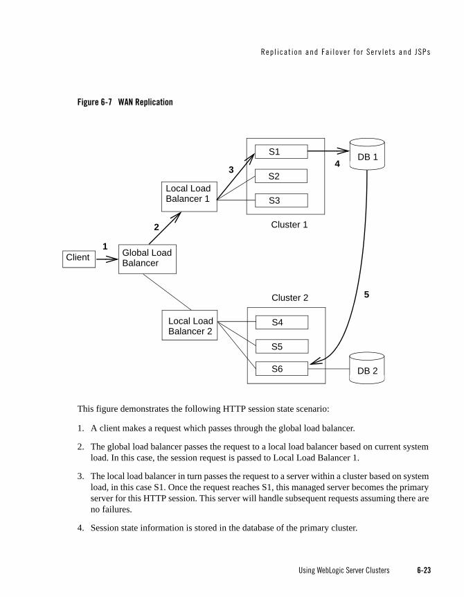
Repl i cat i on and Fa i l ove r f o r Se rv le ts and JSPs
Using WebLogic Server Clusters 6-23
Figure 6-7 WAN Replication
This figure demonstrates the following HTTP session state scenario:
1. A client makes a request which passes through the global load balancer.
2. The global load balancer passes the request to a local load balancer based on current system load. In this case, the session request is passed to Local Load Balancer 1.
3. The local load balancer in turn passes the request to a server within a cluster based on system load, in this case S1. Once the request reaches S1, this managed server becomes the primary server for this HTTP session. This server will handle subsequent requests assuming there are no failures.
4. Session state information is stored in the database of the primary cluster.
Client Global LoadBalancer
Local LoadBalancer 1
Local LoadBalancer 2
S1
S2
S3
S4
S5
S6
1
2
3 4
Cluster 1
Cluster 2
DB 1
DB 2
5

6-24 Using WebLogic Server Clusters
5. After the server establishes the HTTP session, the current session state is replicated to the designated secondary server.
Failover Scenarios Within a WANThis section describes possible failover scenarios within a WAN environment.
Failover Scenario 1If all of the servers in Cluster 1 fail, the global load balancer will automatically fail all subsequent session requests to Cluster 2. All sessions will be backed up according to the last know flush to the database.
Failover Scenario 2Assume that the primary server S1 is being hosted on Cluster 1, and the secondary server S6 is being hosted on Cluster 2. If S1 crashes, then S6 will become the new primary server. The session state will be backed up on a new secondary sever.
Database Configuration for WAN Session State ReplicationThis section describes the data source configuration requirements for cross-cluster session state replication in a WAN. For more general information about setting up cross-cluster replication, see “Configuration Requirements for Cross-Cluster Replication” on page 6-16.
To enable cross-cluster replication within a WAN environment, you must create a JDBC data source that points to the database where session state information is stored. Perform the following procedures to setup and configure your database:
1. Install and configure your database server software according to your vendor’s documentation.
2. Create a JDBC data source that references this database. For more information on creating a JDBC datasource, see “Configuring JDBC Data Sources” in Configuring and Managing WebLogic JDBC.
This data source can also be configured as a JDBC Multi Data Source. For more information on configuring a Multi Data Source, see “Configuring JDBC Multi Data Sources” in Configuring and Managing WebLogic JDBC.
3. Set the DataSourceForSessionPersistence for both the primary and secondary cluster to point to this data source.
4. Create a table called WLS_WAN_PERSISTENCE in your database according to the following schema:

Repl icat ion and Fa i l ove r fo r E JBs and RMIs
Using WebLogic Server Clusters 6-25
CREATE TABLE WLS_WAN_PERSISTENCE_TABLE (WL_ID VARCHAR2(100) NOT NULL,WL_CONTEXT_PATH VARCHAR2(50) NOT NULL,WL_CREATE_TIME NUMBER(20),WL_ACCESS_TIME NUMBER(20),WL_MAX_INACTIVE_INTERVAL NUMBER(38),WL_VERSION NUMBER(20) NOT NULL,WL_INTERNAL_ATTRIBUTE NUMBER(38),WL_SESSION_ATTRIBUTE_KEY VARCHAR2(100),WL_SESSION_ATTRIBUTE_VALUE LONG RAW,PRIMARY KEY(WL_ID, WL_CONTEXT_PATH,WL_VERSION, WL_SESSION_ATTRIBUTE_KEY));
The following table describes what each row of this table contains:
Replication and Failover for EJBs and RMIsFor clustered EJBs and RMIs, failover is accomplished using the object’s replica-aware stub. When a client makes a call through a replica-aware stub to a service that fails, the stub detects the failure and retries the call on another replica.
With clustered objects, automatic failover generally occurs only in cases where the object is idempotent. An object is idempotent if any method can be called multiple times with no different effect than calling the method once. This is always true for methods that have no permanent side effects. Methods that do have side effects have to be written with idempotence in mind.
Table 6-3 Contents of Replication Table
Database Row Description
wl_id Stores the HTTP session ID.
wl_context_path Stores the context path to the web application that created the session.
wl_create_time Stores the time the session state was created.
wl_session_values Stores the session attributes.
wl_access_time Stores the time of the last update to the session state.
wl_max_inactive_interval Stores the MaxInactiveInterval of the session state.
wl_version Stores the version of the session. Each update to a session has an associated version.

6-26 Using WebLogic Server Clusters
Consider a shopping cart service call addItem() that adds an item to a shopping cart. Suppose client C invokes this call on a replica on Server S1. After S1 receives the call, but before it successfully returns to C, S1 crashes. At this point the item has been added to the shopping cart, but the replica-aware stub has received an exception. If the stub were to retry the method on Server S2, the item would be added a second time to the shopping cart. Because of this, replica-aware stubs will not, by default, attempt to retry a method that fails after the request is sent but before it returns. This behavior can be overridden by marking a service idempotent.
Clustering Objects with Replica-Aware Stubs If an EJB or RMI object is clustered, instances of the object are deployed on all WebLogic Server instances in the cluster. The client has a choice about which instance of the object to call. Each instance of the object is referred to as a replica.
The key technology that supports object clustering objects in WebLogic Server is the replica-aware stub. When you compile an EJB that supports clustering (as defined in its deployment descriptor), appc passes the EJB’s interfaces through the rmic compiler to generate replica-aware stubs for the bean. For RMI objects, you generate replica-aware stubs explicitly using command-line options to rmic, as described in “WebLogic RMI Compiler,” in Programming WebLogic RMI.
A replica-aware stub appears to the caller as a normal RMI stub. Instead of representing a single object, however, the stub represents a collection of replicas. The replica-aware stub contains the logic required to locate an EJB or RMI class on any WebLogic Server instance on which the object is deployed. When you deploy a cluster-aware EJB or RMI object, its implementation is bound into the JNDI tree. As described in “Cluster-Wide JNDI Naming Service” on page 3-10, clustered WebLogic Server instances have the capability to update the JNDI tree to list all server instances on which the object is available. When a client accesses a clustered object, the implementation is replaced by a replica-aware stub, which is sent to the client.
The stub contains the load balancing algorithm (or the call routing class) used to load balance method calls to the object. On each call, the stub can employ its load algorithm to choose which replica to call. This provides load balancing across the cluster in a way that is transparent to the caller. To understand the load balancing algorithms available for RMI objects and EJBs, see “Load Balancing for EJBs and RMI Objects” on page 5-4. If a failure occurs during the call, the stub intercepts the exception and retries the call on another replica. This provides a failover that is also transparent to the caller.

Repl icat ion and Fa i l ove r fo r E JBs and RMIs
Using WebLogic Server Clusters 6-27
Clustering Support for Different Types of EJBsEJBs differ from plain RMI objects in that each EJB can potentially generate two different replica-aware stubs: one for the EJBHome interface and one for the EJBObject interface. This means that EJBs can potentially realize the benefits of load balancing and failover on two levels:
When a client looks up an EJB object using the EJBHome stub
When a client makes method calls against the EJB using the EJBObject stub
The following sections describe clustering support for different types of EJBs.
Clustered EJBHomes All bean homes interfaces—used to find or create bean instances—can be clustered, by specifying the determined by the home-is-clusterable element in weblogic-ejb-jar.xml.
Note: Stateless session beans, stateful session beans, and entity beans have home interfaces. Message-driven beans do not.
When a bean is deployed to a cluster, each server binds the bean’s home interface to its cluster JNDI tree under the same name. When a client requests the bean’s home from the cluster, the server instance that does the look-up returns a EJBHome stub that has a reference to the home on each server.
When the client issues a create() or find() call, the stub routes selects a server from the replica list in accordance with the load balancing algorithm, and routes the call to the home interface on that server. The selected home interface receives the call, and creates a bean instance on that server instance and executes the call, creating an instance of the bean.
Note: WebLogic Server supports load balancing algorithms that provide server affinity for EJB home interfaces. To understand server affinity and how it affects load balancing and failover, see “Round-Robin Affinity, Weight-Based Affinity, and Random-Affinity” on page 5-8.
Clustered EJBObjectsAn EJBObject stub tracks available replicas of an EJB in a cluster.
Stateless Session BeansWhen a home creates a stateless bean, it returns a EJBObject stub that lists all of the servers in the cluster, to which the bean should be deployed. Because a stateless bean holds no state on behalf of the client, the stub is free to route any call to any server that hosts the bean. The stub

6-28 Using WebLogic Server Clusters
can automatically fail over in the event of a failure. The stub does not automatically treat the bean as idempotent, so it will not recover automatically from all failures. If the bean has been written with idempotent methods, this can be noted in the deployment descriptor and automatic failover will be enabled in all cases.
Note: WebLogic Server supports load balancing options that provide server affinity for stateless EJB remote interfaces. To understand server affinity and how it affects load balancing and failover, see “Round-Robin Affinity, Weight-Based Affinity, and Random-Affinity” on page 5-8.
Stateful Session BeansMethod-level failover for a stateful service requires state replication. WebLogic Server satisfies this requirement by replicating the state of the primary bean instance to a secondary server instance, using a replication scheme similar to that used for HTTP session state.
When a home interface creates a stateless session bean instance, it selects a secondary instance to host the replicated state, using the same rules defined in “Using Replication Groups” on page 6-6. The home interface returns a EJBObject stub to the client that lists the location of the primary bean instance, and the location for the replicated bean state.
The following figure shows a client accessing a clustered stateful session EJB.

Repl icat ion and Fa i l ove r fo r E JBs and RMIs
Using WebLogic Server Clusters 6-29
Figure 6-8 Client Accessing Stateful Session EJB
As the client makes changes to the state of the EJB, state differences are replicated to the secondary server instance. For EJBs that are involved in a transaction, replication occurs immediately after the transaction commits. For EJBs that are not involved in a transaction, replication occurs after each method invocation.
In both cases, only the actual changes to the EJB’s state are replicated to the secondary server. This ensures that there is minimal overhead associated with the replication process.
Note: The actual state of a stateful EJB is non-transactional, as described in the EJB specification. Although it is unlikely, there is a possibility that the current state of the EJB can be lost. For example, if a client commits a transaction involving the EJB and there is a failure of the primary server before the state change is replicated, the client will fail over to the previously-stored state of the EJB. If it is critical to preserve the state of your EJB in all possible failover scenarios, use an entity EJB rather than a stateful session EJB.
Instance of
State of
WebLogic ServerCluster
Client
A
B
C
Object “A” StubPrimary State:
Secondary State:
A
B
Object ‘A’
Object ‘A’

6-30 Using WebLogic Server Clusters
Failover for Stateful Session EJBsShould the primary server fail, the client’s EJB stub automatically redirects further requests to the secondary WebLogic Server instance. At this point, the secondary server creates a new EJB instance using the replicated state data, and processing continues on the secondary server.
After a failover, WebLogic Server chooses a new secondary server to replicate EJB session states (if another server is available in the cluster). The location of the new primary and secondary server instances is automatically updated in the client’s replica-aware stub on the next method invocation, as shown below.
Figure 6-9 Replica Aware Stubs are Updated after Failover
Entity EJBsThere are two types of entity beans to consider: read-write entity beans and read-only entity beans.
Read-Write Entities
Instance of
State of
WebLogic ServerCluster
Client
A
B
C
Object “A” StubPrimary State:Primary State: B
Object ‘A’
Secondary State: C
AInstance ofObject ‘A’
Object ‘A’

Repl icat ion and Fa i l ove r fo r E JBs and RMIs
Using WebLogic Server Clusters 6-31
When a home finds or creates a read-write entity bean, it obtains an instance on the local server and returns a stub pinned to that server. Load balancing and failover occur only at the home level. Because it is possible for multiple instances of the entity bean to exist in the cluster, each instance must read from the database before each transaction and write on each commit.
Read-Only Entities
When a home finds or creates a read-only entity bean, it returns a replica-aware stub. This stub load balances on every call but does not automatically fail over in the event of a recoverable call failure. Read-only beans are also cached on every server to avoid database reads.
Failover for Entity Beans and EJB Handles Failover for entity beans and EJB handles depends upon the existence of the cluster address. You can explicitly define the cluster address, or allow WebLogic Server to generate it automatically, as described in “Cluster Address” on page 10-6. If you explicitly define cluster address, you must specify it as a DNS name that maps to all server instances in the cluster and only server instances in the cluster. The cluster DNS name should not map to a server instance that is not a member of the cluster.
Clustering Support for RMI ObjectsWebLogic RMI provides special extensions for building clustered remote objects. These are the extensions used to build the replica-aware stubs described in the EJB section. For more information about using RMI in clusters, see “WebLogic RMI Features and Guidelines” in Programming WebLogic RMI.
Object Deployment RequirementsIf you are programming EJBs to be used in a WebLogic Server cluster, read the instructions in this section to understand the capabilities of different EJB types in a cluster. Then ensure that you enable clustering in the EJB’s deployment descriptor. “weblogic-ejb-jar.xml Deployment Descriptor Reference” in Programming WebLogic Enterprise JavaBeans describes the XML deployment elements relevant for clustering.
If you are developing either EJBs or custom RMI objects, also refer to “Using WebLogic JNDI in a Clustered Environment” in Programming WebLogic JNDI to understand the implications of binding clustered objects in the JNDI tree.

6-32 Using WebLogic Server Clusters
Other Failover ExceptionsEven if a clustered object is not idempotent, WebLogic Server performs automatic failover in the case of a ConnectException or MarshalException. Either of these exceptions indicates that the object could not have been modified, and therefore there is no danger of causing data inconsistency by failing over to another instance.
Failover and JDBC ConnectionsJDBC is a highly stateful client-DBMS protocol, in which the DBMS connection and transactional state are tied directly to the socket between the DBMS process and the client (driver). For this reason, failover of a connection is not supported. If a WebLogic Server instance dies, any JDBC connections that it managed will die, and the DBMS(s) will roll back any transactions that were under way. Any applications affected will have to restart their current transactions from the beginning. All JDBC objects associated with dead connections will also be defunct. Clustered JDBC eases the reconnection process: the cluster-aware nature of WebLogic data sources in external client applications allow a client to request another connection from them if the server instance that was hosting the previous connection fails.
If you have replicated, synchronized database instances, you can use a JDBC multi data source to support database failover. In such an environment, if a client cannot obtain a connection from one data source in the multi data source because the data source doesn’t exist or because database connectivity from the data source is down, WebLogic Server will attempt to obtain a connection from the next data source in the list of data sources.
For instructions on clustering JDBC objects, see “Configure Clustered JDBC” on page 10-24.
Note: Any data source assigned to a multi data source must be configured to test its connections at reserve time. This is the only way a pool can verify it has a good connection, and the only way a multi data source can know when to fail over to the next pool on its list.

Using WebLogic Server Clusters 7-1
C H A P T E R 7
Whole Server Migration
The following sections describe the different migration mechanisms supported by WebLogic Server:
“Understanding Whole Server and Service Migration” on page 7-1
“Migration Terminology” on page 7-2
“Leasing” on page 7-3
“Automatic Whole Server Migration” on page 7-7
These sections focus on whole server-level migration, where a migratable server instance, and all of its services, is migrated to a different physical machine upon failure. WebLogic Server also supports service-level migration, as well as replication and failover at the application level. For more information, see Chapter 8, “Service-Level Migration” and Chapter 6, “Failover and Replication in a Cluster”.
Understanding Whole Server and Service MigrationNote: Whole server migration is not supported on all platforms. See Server Migration in
Supported Configurations for WebLogic Platform 10.0.
In a WebLogic Server cluster, most services are deployed homogeneously on all server instances in the cluster, enabling transparent failover from one server to another. In contrast, “pinned services” such as JMS and the JTA transaction recovery system are targeted at individual server instances within a cluster—for these services, WebLogic Server supports failure recovery with migration, as opposed to failover.

7-2 Using WebLogic Server Clusters
Migration in WebLogic Server is the process of moving a clustered WebLogic Server instance or a component running on a clustered instance elsewhere in the event of failure. In the case of whole server migration, the server instance is migrated to a different physical machine upon failure. In the case of service-level migration, the services are moved to a different server instance within the cluster. See Chapter 8, “Service-Level Migration.”
WebLogic Server provides a feature for making JMS and the JTA transaction system highly available: migratable servers. Migratable servers provide for both automatic and manual migration at the server-level, rather than the service level.
Note: Server migration is only supported when you use the SSH version of Node Manager. Server migration is not supported on Windows.
When a migratable server becomes unavailable for any reason, for example, if it hangs, loses network connectivity, or its host machine fails—migration is automatic. Upon failure, a migratable server is automatically restarted on the same machine if possible. If the migratable server cannot be restarted on the machine where it failed, it is migrated to another machine. In addition, an administrator can manually initiate migration of a server instance.
Migration TerminologyThe following terms apply to server and service migration:
Migratable server—A clustered server instance that migrates in its entirety, along with all the services it hosts. Migratable servers are intended to host pinned services, such as JMS servers and the JTA transaction recovery servers, but they can also host clusterable services. All services that run on a migratable server are highly available.
Server migration—Server-level migration allows a WebLogic Server instance to be configured
Manual Service-level Migration—You can manually migrate pinned JTA and JMS-related services (e.g., JMS server, SAF agent, path service, and custom persistent store) after the host server instance fails. See Chapter 8, “Service-Level Migration.”
Automatic JTA Service Migration—Automatic service-level migration allows the JTA Transaction Recovery Service to be configured to be migrated to another server automatically. When a server fails or is restarted, this service is migrated automatically. See Chapter 8, “Service-Level Migration.”
Cluster master—One server instance in a cluster that contains migratable servers acts as the cluster master and orchestrates the process of automatic server migration, in the event of failure. Any Managed Server in a cluster can serve as the cluster master, whether it hosts

Leas ing
Using WebLogic Server Clusters 7-3
pinned services or not. See “Cluster Master’s Role in Whole Server Migration” on page 7-18.
Migration master—A lightweight singleton service that monitors other services that can be migrated automatically. The server that currently hosts the migration master is responsible for starting and stopping the migration tasks associated with each migratable service. See “Migration Master” on page 8-22.
Candidate machines—A user-defined list of machines within a cluster that can be a potential target for migration.
Target machines—A set of machines that are designated as allowable or preferred hosts for migratable servers.
Node Manager—Node Manager is used by the Administration Server or a stand-alone Node Manager client, to start and stop migratable servers, and is invoked by the cluster master to shut down and restart migratable servers, as necessary.
For background information about Node Manager and how it fits into a WebLogic Server environment, see “Using Node Manager to Control WebLogic Server” in Configuring WebLogic Server Environments.
Lease table—You can configure a database table in which migratable servers persist their state, and which the cluster master monitors to verify the health and liveness migratable servers. For more information on leasing, see “Leasing” on page 7-3.
Administration Server—Used to configure migratable servers and target machines, to obtain the runtime state of migratable servers, and to orchestrate the manual migration process.
LeasingLeasing is the process WebLogic Server uses to manage services that are required to run on only one member of a cluster at a time. Leasing ensures exclusive ownership of a cluster-wide entity. Within a cluster, there is a single owner of a lease. Additionally, leases can failover in case of server or cluster failure. This helps to avoid having a single point of failure.
Features That Use LeasingThe following WebLogic server features use leasing:

7-4 Using WebLogic Server Clusters
Automatic Whole Server Migration — Uses leasing to elect a cluster master. The cluster master is responsible for monitoring other cluster members. It is also responsible for restarting failed members hosted on other physical machines.
Leasing ensures that the cluster master is always running, but is only running on one server at a time within a cluster. For information on the cluster master, see “Cluster Master’s Role in Whole Server Migration” on page 7-18.
Automatic JTA Service Migration — The JTA Transaction Recovery Service can be configured to automatically migrate from a unhealthy hosting server to a healthy active server with the help of the Health Monitoring subsystem. When the migratable target is migrated, the pinned Transaction Recovery Service hosted by that target is migrated. Migratable targets use leasing to accomplish automatic Transaction Recovery Service migration. See Chapter 8, “Service-Level Migration.”.
Singleton Services — A singleton service is, by definition, a service running within a cluster that is available on only one member of the cluster at a time. Singleton services use leasing to accomplish this. See “Migration Master” on page 8-22.
Job Scheduler — The Job Scheduler is a persistent timer that is used with in a cluster. The Job Scheduler uses the timer master to load balance the timer across a cluster.
Note: Although you can use the use the non-database version of Consensus leasing with the Job Scheduler, this feature requires an external database to maintain failover and replication information.
Note: Beyond basic configuration, most leasing functionality is handled internally by WebLogic Server.
Leasing VersionsWebLogic Server provides two separate implementations of the leasing functionality. Which one you use depends on your requirements and your environment.
High-availability database leasing — This version of leasing requires the availability of a high-availability database to store leasing information. For information on general requirements and configuration, see “High-availability Database Leasing” on page 7-5.
Non-database Consensus leasing — This version of leasing stores the leasing information in-memory within a cluster member. For more information, see “Non-database Consensus Leasing” on page 7-6.

Leas ing
Using WebLogic Server Clusters 7-5
Note: Within a WebLogic Server installation, you can only use one type of leasing. Although it is possible to implement multiple features that use leasing within your environment, each must use the same kind of leasing.
Note: When switching from one leasing type to another, you must restart the entire cluster, not just the Administration Server. Changing the leasing type cannot be done dynamically.
Determining Which Leasing Type to UseThe following considerations will help you determine which type of leasing is appropriate to your WebLogic Server environment:
Non-database Consensus Leasing
This type of leasing provides a leasing basis option (consensus) that does not require the use of a HA database like Oracle RAC. This has direct benefit in automatic whole server migration since the HA database requirement is removed with consensus leasing. This means less configuration is required to enable automatic server migration.
Consensus leasing basis requires Node Manager to be configured and running. Automatic whole server migration also requires the Node Manager for IP migration and server restart on another machine. Hence, consensus leasing works well since it does not impose additional requirements, but instead takes away an expensive one.
High-availability Database Leasing
DB-leasing basis is still useful in cases in environments that are already invested in a HA database, like Oracle RAC, for features like JMS store recovery. The HA database instance can also be configured to support leasing with minimal additional configuration. This is particularly useful if Node Manager is not running in the system.
High-availability Database LeasingIn this version of leasing, lease information is maintained within a table in a high-availability. A high-availability database is required to ensure that leasing information is always available. Each member of the cluster must be able to connect to the database in order to access leasing information.
This method of leasing is useful for customers who already have a high-availability database within their clustered environment. This method allows you to utilize leasing functionality without being required to use Node Manager to manage servers within your environment.
The following procedures outline the steps required to configure your database for leasing.

7-6 Using WebLogic Server Clusters
1. Configure the database for server migration. This information that is used to determine whether or not a server is running or needs to be migrated. For more information on leasing, see “Leasing” on page 7-3.
Your database must be reliable. The server instances will only be as reliable as the database is. For experimental purposes, a normal database will suffice. For a production environment, only high-availability databases are recommended. If the database goes down, all the migratable servers will shut themselves down.
Create the leasing table in the database. This is used to store the machine-server associations used to enable server migration. The schema for this table is located in:
<WL_HOME>/server/db/<dbname>/leasing.ddl
where dbname is the name of the database vendor.
Note: The leasing table should be stored in a highly available database. Migratable servers are only as reliable as the database used to store the leasing table.
2. Set up and configure a data source. This data source should point to the database configured in the previous step.
Note: XA data sources are not supported for server migration.
For more information on creating a JDBC data source, see “Configuring JDBC Data Sources” in Configuring and Managing WebLogic JDBC.
Non-database Consensus LeasingIn the non-database version of Consensus leasing, WebLogic Server maintains leasing information in-memory. This removes the requirement of having a high-availability database to use features that require leasing.
One member of a cluster is chosen as the cluster leader and is responsible for maintaining the leasing information. The cluster leader is chosen based on the length of time that has passed since startup. The managed server that has been running the longest within a cluster is chosen as the cluster leader. Other cluster members communicate with this server to determine leasing information, however, the leasing table is replicated to other nodes of the cluster to provide failover.
Note: This version of leasing requires that you use Node Manager to control servers within the cluster. Node Manager should also be running on every machine hosting managed servers within the cluster. For more information, see Using Node Manager to Control Servers.

Automat ic Who le Se rve r Migrat ion
Using WebLogic Server Clusters 7-7
Automatic Whole Server MigrationThis section outlines the procedures for configuring server migration and provides a general discussion of how server migration functions within a WebLogic Server environment.
The following topics are covered:
“Preparing for Automatic Whole Server Migration” on page 7-7
“Configuring Automatic Whole Server Migration” on page 7-8
“Using High Availability Storage for State Data” on page 7-10
“Server Migration Processes and Communications” on page 7-10
Preparing for Automatic Whole Server MigrationBefore configuring server migration, be aware of the following requirements:
Verify that whole server migration is supported on your platform. See Server Migration in Supported Configurations for WebLogic Platform 10.0.
Caution: Automatic whole server migration is not supported on Solaris 10 systems using the Solaris Zones feature. For more information, see Product Support Information Supported Configurations.
Each Managed Server uses the same subnet mask. Unicast and multicast communication among servers requires each server to use the same subnet. Server migration will not work without multicast or unicast communication being configured.
For information on using multicast, see “Using IP Multicast for Backward Compatibility” on page 3-2. For information on using unicast, see “One-to-Many Communication Using Unicast” on page 3-4.
All servers hosting migratable servers are time-synchronized. Although migration works when servers are not time-synchronized, time-synchronized servers are recommended in a clustered environment.
If you are using different operating system versions among migratable servers, make sure that all versions support identical functionality for ifconfig.
The primary interface names used by migratable servers are the same. If your environment requires different interface names, then configure a local version of wlscontrol.sh for each migratable server.
7-8 Using WebLogic Server Clusters
For more information on wlsconstol.sh, see Using Node Manager to Control Servers.
See Databases Supporting WebLogic Server Features for a list of databases that WebLogic Server supports Automatic Server migration.
You cannot create Channels/NetworkAccessPoints that have a different Listen Address on a migratable server.
There is no built-in mechanism for transferring files that a server depends on between machines. Using a disk that is accessible from all machines is the preferred way to ensure file availability. If you cannot share disks between servers, you must ensure that the contents of domain_dir/bin are copied to each machine.
Ensure that the Node Manager security files are copied to each machine using the nmEnroll() WLST command. For more information, see Using Node Manager to Control Servers.
Use high availability storage for state data. For highest reliability, use a shared storage solution that is itself highly available—for example, a storage area network (SAN). See “Using High Availability Storage for State Data” on page 7-10.
Configuring Automatic Whole Server MigrationBefore configuring server migration, ensure that your environment meets the requirements outlined in “Preparing for Automatic Whole Server Migration” on page 7-7.
To configure server migration for a Managed Server within a cluster, perform the following tasks:
1. Obtain floating IP addresses for each Managed Server that will have migration enabled.
Each migratable server must be assigned a floating IP address which follows the server from one physical machine to another after migration. Any server that is assigned a floating IP address must also have AutoMigrationEnabled set to true.
Note: The migratable IP address should not be present on the interface of any of the candidate machines before the migratable server is started.
2. Configure Node Manager. Node Manager must be running and configured to allow server migration.
Note: Server migration is only supported using the SSH version of Node Manager.
For general information on using Node Manager in server migration, see “Node Manager’s Role in Whole Server Migration” on page 7-17. For general information on configuring Node Manager, see “Using Node Manager to Control Servers.”

Automat ic Who le Se rve r Migrat ion
Using WebLogic Server Clusters 7-9
3. If you are using a database to manage leasing information, configure the database for server migration according to the procedures outlined in “High-availability Database Leasing” on page 7-5.
For general information on leasing, see “Leasing” on page 7-3.
4. If you are using database leasing within a test environment and you need to reset the leasing table, you should re-run the leasing.ddl script. This causes the correct tables to be dropped and re-created.
5. If you are using a database to store leasing information, set up and configure a data source according to the procedures outlined in “High-availability Database Leasing” on page 7-5.
You should set DataSourceForAutomaticMigration to this data source in each cluster configuration.
Note: XA data sources are not supported for server migration.
For more information on creating a JDBC data source, see “Configuring JDBC Data Sources” in Configuring and Managing WebLogic JDBC.
6. Grant superuser privileges to the wlsifconfig.sh script.
This script is used to transfer IP addresses from one machine to another during migration. It must be able to run ifconfig, which is generally only available to superusers. You can edit the script so that it is invoked using sudo.
This script is available in the $BEA_HOME/wlserver_10.0/common/bin directory.
7. Ensure that wlsifconfig.sh, wlscontrol.sh, and nodemanager.domains are included in your machines' PATH. The .sh files are located in$BEA_HOME/wlserver_10.0/common/bin, and nodemanager.domains is located in $BEA_HOME/wlserver_10.0/common/nodemanager.
Depending on your default shell, you may need to edit the first line of these scripts.
8. The machines that host migratable servers must trust each other. For server migration to occur, it must be possible to get to a shell prompt using 'ssh/rsh machine_A' from machine_B and vice versa without having to explicitly enter a username/password. Also, each machine must be able to connect to itself using SSH in the same way.
Note: You should ensure that your login scripts (.cshrc, .profile, .login, etc.) only echo messages from your shell profile if the shell is interactive. WebLogic Server uses an ssh command to login and echo the contents of the server.state file. Only the first line of this output is used to determine the server state.

7-10 Using WebLogic Server Clusters
9. Set the candidate machines for server migration.Each server can have a different set of Candidate machines, or they can all have the same set.
10. Edit wlscontrol.sh and set the Interface variable to the name of your network interface.
11. Restart the admin server.
Using High Availability Storage for State DataThe server migration process migrates services, but not the state information associated with work in process at the time of failure.
To ensure high availability, it is critical that such state information remains available to the server instance and the services it hosts after migration. Otherwise, data about the work in process at the time of failure may be lost. State information maintained by a migratable server, such as the data contained in transaction logs, should be stored in a shared storage system that is accessible to any potential machine to which a failed migratable server might be migrated. For highest reliability, use a shared storage solution that is itself highly available—for example, a storage area network (SAN).
In addition, if you are using a database to store leasing information, the lease table, described in the following sections, which is used to track the health and liveness of migratable servers should also stored in a high availability database. For more information, see “Leasing” on page 7-3.
Server Migration Processes and CommunicationsThe sections that follow describe key processes in a cluster that contains migratable servers:
“Startup Process in a Cluster with Migratable Servers” on page 7-10
“Automatic Migration Process” on page 7-12
“Manual Migration Process” on page 7-14
Startup Process in a Cluster with Migratable ServersFigure 7-1, “Startup of Cluster with Migratable Servers,” on page 7-11 illustrates the processing and communications that occur during startup of a cluster that contains migratable servers.
The example cluster contains two Managed Servers, both of which are migratable. The Administration Server and the two Managed Servers each run on different machines. A fourth machine is available as a backup—in the event that one of the migratable servers fails. Node

Automat ic Who le Se rve r Migrat ion
Using WebLogic Server Clusters 7-11
Manager is running on the backup machine and on each machine with a running migratable server.
Figure 7-1 Startup of Cluster with Migratable Servers
These are the key steps that occur during startup of the cluster illustrated in Figure 7-1:
7-12 Using WebLogic Server Clusters
1. The administrator starts up the cluster.
2. The Administration Server invokes Node Manager on Machines B and C to start Managed Servers 1 and 2, respectively. See “Administration Server’s Role in Whole Server Migration” on page 7-16.
3. The Node Manager on each machine starts up the Managed Server that runs there. See “Node Manager’s Role in Whole Server Migration” on page 7-17.
4. Managed Servers 1 and 2 contact the Administration Server for their configuration. See “Migratable Server Behavior in a Cluster” on page 7-16.
5. Managed Servers 1 and 2 cache the configuration they started up.
6. Managed Servers 1 and 2 each obtain a migratable server lease in the lease table. Because Managed Server 1 starts up first, it also obtains a cluster master lease. See “Cluster Master’s Role in Whole Server Migration” on page 7-18.
7. Managed Server 1 and 2 periodically renew their leases in the lease table, proving their health and liveness.
Automatic Migration ProcessFigure 7-2, “Automatic Migration of a Failed Server,” on page 7-13 illustrates the automatic migration process after the failure of the machine hosting Managed Server 2.

Automat ic Who le Se rve r Migrat ion
Using WebLogic Server Clusters 7-13
Figure 7-2 Automatic Migration of a Failed Server
1. Machine C, which hosts Managed Server 2, fails.
2. Upon its next periodic review of the lease table, the cluster master detects that Managed Server 2’s lease has expired. See “Cluster Master’s Role in Whole Server Migration” on page 7-18.

7-14 Using WebLogic Server Clusters
3. The cluster master tries to contact Node Manager on Machine C to restart Managed Server 2, but fails, because Machine C is unreachable.
Note: If the Managed Server 2’s lease had expired because it was hung, and Machine C was reachable, the cluster master would use Node Manager to restart Managed Server 2 on Machine C.
4. The cluster master contacts Node Manager on Machine D, which is configured as an available host for migratable servers in the cluster.
5. Node Manager on Machine D starts Managed Server 2. See “Node Manager’s Role in Whole Server Migration” on page 7-17.
6. Managed Server 2 starts up and contacts the Administration Server to obtain its configuration.
7. Managed Server 2 caches the configuration it started up with.
8. Managed Server 2 obtains a migratable server lease.
During migration, the clients of the Managed Server that is migrating may experience a brief interruption in service; it may be necessary to reconnect. On Solaris and Linux operating systems, this can be done using ifconfig command. The clients of a migrated server do not need to know the particular machine to which it has migrated.
When a machine that previously hosted a server instance that was migrated becomes available again, the reversal of the migration process—migrating the server instance back to its original host machine—is known as failback. WebLogic Server does not automate the process of failback. An administrator can accomplish failback by manually restoring the server instance to its original host.
The general procedures for restoring a server to its original host are as follows:
Gracefully shutdown the new instance of the server
After you have restarted the failed machine, restart Node Manager and the managed server.
The exact procedures you will follow depend on your server and network environment.
Manual Migration ProcessFigure 7-3, “Manual Server Migration,” on page 7-15 illustrates what happens when an administrator manually migrates a migratable server.

Automat ic Who le Se rve r Migrat ion
Using WebLogic Server Clusters 7-15
Figure 7-3 Manual Server Migration
1. An administrator uses the Administration Console to initiate the migration of Managed Server 2 from Machine C to Machine B.
2. The Administration Server contacts Node Manager on Machine C. See “Administration Server’s Role in Whole Server Migration” on page 7-16.
3. Node Manager on Machine C stops Managed Server 2.
4. Managed Server 2 removes its row from the lease table.
5. The Administration Server invokes Node Manager on Machine B.
6. Node Manager on Machine B starts Managed Server 2.
7. Managed Server 2 obtains its configuration from the Administration Server.

7-16 Using WebLogic Server Clusters
8. Managed Server 2 caches the configuration it started up with.
9. Managed Server 2 adds a row to the lease table.
Administration Server’s Role in Whole Server MigrationIn a cluster that contains migratable servers, the Administration Server:
Invokes Node Manager, on each machine that hosts cluster members, to start up the migratable servers. This is a prerequisite for server migratability—if a server instance was not initially started by Node Manager, it cannot be migrated.
Invokes Node Manager on each machine involved in a manual migration process to stop and start the migratable server.
Invokes Node Manager on each machine that hosts cluster members to stop server instances during a normal shutdown. This is a prerequisite for server migratability—if a server instance is shut down directly, without using Node Manager, when the cluster master detects that the server instance is not running, it will call Node Manager to restart it.
In addition, the Administration Server provides its regular domain management functionality, persisting configuration updates issued by an administrator, and providing a run-time view of the domain, including the migratable servers it contains.
Migratable Server Behavior in a ClusterA migratable server is a clustered Managed Server that has been configured as migratable. These are the key behaviors of a migratable server:
If you are using a database to manage leasing information, during startup and restart by Node Manager, a migratable server adds a row to the lease table. The row for a migratable server contains a timestamp, and the machine where it is running.
For more information, see on leasing, see “Leasing” on page 7-3.
When using a database to manage leasing information, a migratable server adds a row to the database as a result of startup, it tries to take on the role of cluster master, and succeeds if it is the first server instance to join the cluster.
Periodically, the server renews its “lease” by updating the timestamp in the lease table.
By default a migratable server renews its lease every 30,000 milliseconds—the product of two configurable ServerMBean properties:
– HealthCheckIntervalMillis, which by default is 10,000.

Automat ic Who le Se rve r Migrat ion
Using WebLogic Server Clusters 7-17
– HealthCheckPeriodsUntilFencing, which by default is 3.
If a migratable server fails to reach the lease table and renew its lease before the lease expires, it terminates as quickly as possible using a Java System.exit—in this case, the lease table still contains a row for that server instance. For information about how this relates to automatic migration, see Cluster Master’s Role in Whole Server Migration.
During operation, a migratable server listens for heartbeats from the cluster master. When it detects that the cluster master is not sending heartbeats, it attempts to take over the role of cluster master, and succeeds if no other server instance has claimed that role.
Node Manager’s Role in Whole Server MigrationThe use of Node Manager is required for server migration—it must run on each machine that hosts, or is intended to host.
Node Manager supports server migration in these ways:
Node Manager must be used for initial startup of migratable servers.
When you initiate the startup of a Managed Server from the Administration Console, the Administration Server uses Node Manager to start up the server instance. You can also invoke Node Manager to start the server instance using the stand-alone Node Manager client; however, the Administration Server must be available so that the Managed Server can obtain its configuration.
Note: Migration of a server instance that not initially started with Node Manager will fail.
Node Manager must be used for suspend, shutdown, or force shutdown of migratable servers.
Node Manager tries to restart a migratable server whose lease has expired on the machine where it was running at the time of failure.
Node Manager performs the steps in the server migrate process by running customizable shell scripts, provided with WebLogic Server, that start, restart and stop servers; migrate IP addresses; and mount and unmount disks. The scripts are available for Solaris and Linux.
– In an automatic migration, the cluster master invokes Node Manager to perform the migration.
– In a manual migration, the Administration Server invokes Node Manager to perform the migration.

7-18 Using WebLogic Server Clusters
Cluster Master’s Role in Whole Server MigrationIn a cluster that contains migratable servers, one server instance acts as the cluster master. Its role is to orchestrate the server migration process. Any server instance in the cluster can serve as the cluster master. When you start a cluster that contains migratable servers, the first server to join the cluster becomes the cluster master and starts up the cluster manager service. If a cluster does not include at least one migratable server, it does not require a cluster master, and the cluster master service does not start up. In the absence of a cluster master, migratable servers can continue to operate, but server migration is not possible. These are the key functions of the cluster master:
Issues periodic heartbeats to the other servers in the cluster.
Periodically reads the lease table to verify that each migratable server has a current lease. An expired lease indicates to the cluster master that the migratable server should be restarted.
Upon determining that a migratable server’s lease is expired, waits for period specified by the FencingGracePeriodMillis on the ClusterMBean, and then tries to invoke the Node Manager process on the machine that hosts the migratable server whose lease is expired, to restart the migratable server.
If unable to restart a migratable server whose lease has expired on its current machine, the cluster master selects a target machine in this fashion:
– If you have configured a list of preferred destination machines for the migratable server, the cluster master chooses a machine on that list, in the order the machines are listed.
– Otherwise, the cluster master chooses a machine on the list of those configured as available for hosting migratable servers in the cluster.
A list of machines that can host migratable servers can be configured at two levels: for the cluster as a whole, and for an individual migratable server. You can define a machine list at both levels. You must define a machine list at least one level.
To accomplish the migration of a server instance to a new machine, the cluster master invokes the Node Manager process on the target machine to create a process for the server instance.
The time required to perform the migration depends on the server configuration and startup time.

Automat ic Who le Se rve r Migrat ion
Using WebLogic Server Clusters 7-19
– The maximum time taken for cluster master to restart the migratable server is (HealthCheckPeriodsUntilFencing * HealthCheckIntervalMillis) + FencingGracePeriodMillis.
– The total time before the server becomes available for client requests depends on the server startup time and the application deployment time.

7-20 Using WebLogic Server Clusters

Using WebLogic Server Clusters 8-1
C H A P T E R 8
Service-Level Migration
The following sections describe the service-level migration mechanisms supported by WebLogic Server:
“Understanding the Service-Level Migration Framework” on page 8-2
“Pre-Migration Requirements” on page 8-10
“Roadmap for Configuring Manual Migration of JMS-Related Services” on page 8-13
“Roadmap for Configuring Automatic Migration of the JTA Transaction Recovery Service” on page 8-17
“Manual Migration of the JTA Transaction Recovery Service” on page 8-21
“Automatic Migration of User-Defined Singleton Services” on page 8-22
These sections focus on the migration of failed services. WebLogic Server also supports whole server-level migration, where a migratable server instance, and all of its services, is migrated to a different physical machine upon failure. For information on failed server migration, see Chapter 7, “Whole Server Migration.”
WebLogic Server also supports replication and failover at the application level. For more information, see Chapter 6, “Failover and Replication in a Cluster”.

8-2 Using WebLogic Server Clusters
Understanding the Service-Level Migration FrameworkIn a WebLogic Server cluster, most subsystem services are hosted homogeneously on all server instances in the cluster, enabling transparent failover from one server to another. In contrast, pinned services, such as messaging-related services, the JTA Transaction Recovery Service, and user-defined singleton services are hosted on individual server instances within a cluster—for these services, the WebLogic Server migration framework supports failure recovery with service migration, as opposed to failover. See “Migratable Services” on page 8-2.
Service-level migration in WebLogic Server is the process of moving the pinned services from one instance server instance to a different available server instance within the cluster. Service migration is controlled by logical migratable target, which serves as a grouping of services that is hosted on only one physical server in a cluster. You can select a migratable target in place of a server or cluster when targeting certain pinned services. High availability is achieved by migrating a migratable target from one clustered server to another when a problem occurs on the original server. You can also manually migrate a migratable target for scheduled maintenance. See “Understanding Migratable Targets In a Cluster” on page 8-4.
The migration framework provides tools and infrastructure for configuring and migrating targets. See “Migration Processing Tools” on page 8-7 and “Automatic Service Migration Infrastructure for JTA” on page 8-7. For definitions of the terms that apply to server and service migration, see “Migration Terminology” on page 7-2.
Migratable ServicesWebLogic Server supports service-level migration for JMS-related services, the JTA Transaction Recovery Service, and user-defined singleton services. These are referred to as migratable services, because you can move them from one server to another within a cluster. The following migratable services can be configured for manual migration:
Messaging/JMS-related ServicesJMS services are singleton services, and, therefore, are not active on all server instances in a cluster. Instead, they are pinned to a single server in the cluster to preserve data consistency. To ensure that singleton JMS services do not introduce a single point of failure for dependent applications in the cluster, WebLogic Server can be configured to manually migrate them to any server instance in the migratable target list.

Unders tand ing the Se rv i ce-Leve l M igrat ion F ramework
Using WebLogic Server Clusters 8-3
JMS Server – management containers for the queues and topics in JMS modules that are targeted to them. See JMS Server Configuration in Configuring and Managing WebLogic JMS.
Store-and-Forward (SAF) Service – store-and-forward messages between local sending and remote receiving endpoints, even when the remote endpoint is not available at the moment the messages are sent. Only sending SAF agents configured for JMS SAF (sending capability only) are migratable. See Configuring and Managing WebLogic Store-and-Forward.
Path Service – a persistent map that can be used to store the mapping of a group of messages in a JMS Message Unit-of-Order to a messaging resource in a cluster. It provides a way to enforce ordering by pinning messages to a member of a cluster hosting servlets, distributed queue members, or Store-and-Forward agents. One path service is configured per cluster. See Using the WebLogic Path Service in Configuring and Managing WebLogic JMS.
Custom Persistent Store – a user-defined, disk-based file store or JDBC-accessible database for storing subsystem data, such as persistent JMS messages or store-and-forward messages. See Using the WebLogic Persistent Store in Configuring WebLogic Server Environments.
JTA Transaction Recovery ServiceThe Transaction Recovery Service automatically attempts to recover transactions on system startup by parsing all transaction log records for incomplete transactions and completing them. For detailed information, see Transaction Recovery After a Server Fails in Programming WebLogic JTA.
User-defined Singleton ServicesWithin an application, you can define a singleton service that can be used to perform tasks that you want to be executed on only one member of a cluster at any give time. See “Automatic Migration of User-Defined Singleton Services” on page 8-22.

8-4 Using WebLogic Server Clusters
Understanding Migratable Targets In a ClusterYou can configure JMS and JTA services for high availability by using migratable targets. A migratable target is a special target that can migrate from one server in a cluster to another. As such, a migratable target provides a way to group migratable services that should move together. When the migratable target is migrated, all services hosted by that target are migrated.
In order to configure a migratable JMS service for migration, it must be deployed to a migratable target. A migratable target specifies a set of servers that can host a target, and can optionally specify a user-preferred host for the services and an ordered list of candidate backup servers should the preferred server fail. Only one of these servers can host the migratable target at any one time.
Once a service is configured to use a migratable target, then the service is independent from the server member that is currently hosting it. For example, if a JMS server with a deployed JMS queue is configured to use a migratable target, then the queue is independent of when a specific server member is available. In other words, the queue is always available when the migratable target is hosted by any server in the cluster.
An administrator can manually migrate pinned migratable services from one server instance to another in the cluster, either in response to a server failure or as part of regularly scheduled maintenance. If you do not configure a migratable target in the cluster, migratable services can be migrated to any WebLogic Server instance in the cluster. See the “Roadmap for Configuring Manual Migration of JMS-Related Services” on page 8-13.
User-Preferred Servers and Candidate ServersWhen deploying a JMS service to the migratable target, you can select a the user-preferred server (UPS) target to host the service. When configuring a migratable target, you can also specify constrained candidate servers (CCS) that can potentially host the service should the user-preferred server fail. If the migratable target does not specify a constrained candidate server, the JMS server can be migrated to any available server in the cluster.
WebLogic Server enables you to create separate migratable targets for JMS services. This allows you to always keep each service running on a different server in the cluster, if necessary. Conversely, you can configure the same selection of servers as the constrained candidate servers for both JTA and JMS, to ensure that the services remain co-located on the same server in the cluster.

Unders tand ing the Se rv i ce-Leve l M igrat ion F ramework
Using WebLogic Server Clusters 8-5
Targeting Rules for JMS ServersWhen not using migratable targets, a JMS server can be targeted to a specific cluster member and can use either the default file or a custom store. However, when targeted to a migratable target, a JMS server must use a custom persistent store, and must be targeted to the same migratable target used by the custom store. A JMS server, SAF agent, and custom store can share a migratable target. See “Custom Store Availability for JMS Services” on page 8-10.
Targeting Rules for SAF AgentsWhen not using migratable targets, a SAF agent can be targeted to an entire cluster or a list of multiple servers in a cluster, with the requirement that the SAF agent and each server in the cluster must use the default persistent store. However, when targeted to a migratable target, a SAF agent can only be targeted to that migratable target. It must also use a custom persistent store, and, like a JMS server, must targeted to the same migratable target used by the custom store. A SAF agent, JMS server, and custom store can share a migratable target.
In addition, consider the following topics when targeting SAF agents to migratable targets.
Re-targeting SAF Agents to Migratable TargetsTo preserve SAF message consistency, WebLogic Server prevents you from retargeting an existing SAF agent to a migratable target. Instead, you must delete the existing SAF agent and configure a new one with the same values and target it to a migratable target.
Targeting Migratable SAF Agents For Increased Message ThroughputWhen not using migratable targets, a SAF agent can be targeted to an entire cluster or multiple servers in a cluster for increased message throughput. However, When a SAF agent is targeted to a migratable target, it cannot be targeted to any other servers in the cluster, including an entire cluster. Therefore, if you want to increase throughput by importing a JMS destination to multiple SAF agents on separate servers in a cluster, then you should create migratable targets for each server in the cluster, and then create separate SAF agents that are targeted individually to each migratable target.
Targeting SAF Agents For Consistent Quality-of-ServiceA Weblogic administrator has the freedom to configure and deploy multiple SAF agents in the same cluster or on the same server. As such, there could be situations where the same server has both migratable SAF agents and non-migratable ones. For such cases, the behavior of a JMS client application may vary depending on which SAF agent handles the messages.

8-6 Using WebLogic Server Clusters
For example, an imported destination can be deployed to multiple SAF agents, and messages sent to the imported destination will be load-balanced among all SAF agents. If the list of the SAF agents contains non-migratable agents, the JMS client application may have a limited sense of HA (high availability). Therefore, a recommended best practice is to deploy an imported destination to one or more SAF agents that provide the same level of HA functionality. In other words, to get consistent forwarding quality and behavior, you should target the imported destination to a set of SAF agents that are all targeted to migratable targets or are all targeted to non-migratable targets
Targeting Rules for Path ServiceWhen not using migratable targets, a path service is targeted to single member of a cluster, and can use either the default file or a custom store. However, when targeted to a migratable target, a path service cannot use the default store, so a custom store must be configured and targeted to the same migratable target. As an additional best practice, the path service and its custom store should be the only users of that migratable target. Whereas, a JMS server, SAF agent, and custom store can share a migratable target.
Special Considerations For Targeting a Path ServiceWhen the path service for a cluster is targeted to a migratable target, as a best practice, the path service and its custom store should be the only users of that migratable target.
When a path service is targeted to a migratable target its provides enhanced storage of message unit-of-order (UOO) information for JMS distributed destinations, since the UOO information will be based on the entire migratable target instead of being based only on the server instance hosting the distributed destinations member.
Targeting Rules for Custom StoresAs mentioned previously, all JMS-related services require a custom persistent store that is also targeted to the same migratable targets as the JMS services. See “Custom Store Availability for JMS Services” on page 8-10.
Migratable Targets For the JTA Transaction Recovery ServiceFor JTA, migratable target configuration is not necessary for automatic or manual migration because a migratable target is automatically defined for JTA at the server level. The default migration policy for JTA is manual, but when configured for automatic migration, the JTA policy is internally set to failure-recovery. This means that Transaction Recovery Service will only start if its user-preferred server (UPS) is started. If an administrator shuts down the UPS either

Unders tand ing the Se rv i ce-Leve l M igrat ion F ramework
Using WebLogic Server Clusters 8-7
gracefully or forcefully, this service will not be migrated anywhere. However, if the UPS shuts down due to an internal error, then this service will be migrated to another candidate server.
Migration Processing ToolsWebLogic Server migration framework provides infrastructure and facilities to perform the manual migration of JMS-related services and the manual or automatic migration of the JTA Transaction Recovery Service.
Administration ConsoleAn administrator can use the WebLogic Administration Console to configure and/or perform the migration process.
For more information, see the following topics in the Administration Console Help:
Configure JMS service migration
Configure JTA Transaction Recovery Service migration
WebLogic Scripting ToolAn administrator can use the WebLogic Scripting Tool (WLST) command-line interface utility to manage the life cycle of a server instance, including configuring and/or performing the migration process.
For more information, refer to the Life Cycle Commands in WebLogic Scripting Tool.
Automatic Service Migration Infrastructure for JTAThe service migration framework depends on the following components to monitor server health issues and, if necessary, automatically migrate the JTA Transaction Recovery Service to a healthy server.
Leasing for Migratable ServicesLeasing is the process WebLogic Server uses to manage services that are required to run on only one member of a cluster at a time. Leasing ensures exclusive ownership of a cluster-wide entity. Within a cluster, there is a single owner of a lease. Additionally, leases can failover in case of server or cluster failure. This helps to avoid having a single point of failure. See “Leasing” on page 7-3.
8-8 Using WebLogic Server Clusters
Using the Automatic Migration option for the JTA Transaction Recovery Service requires setting a cluster’s Migration Basis policy to either Database or Consensus leasing, as follows:
Database LeasingIf you are using a database to manage leasing information, configure the database for server migration according to the procedures outlined in “High-availability Database Leasing” on page 7-5.
Setting Migration Basis to Database leasing requires that the Data Source For Automatic Migration option is set with a valid JDBC System Resource. It implies that there is a table created on that resource that the Managed Servers will use for leasing. For more information on creating a JDBC data source, see “Configuring JDBC Data Sources” in Configuring and Managing WebLogic JDBC.
Consensus LeasingSetting Migration Basis to Consensus leasing means that the member servers maintain leasing information in-memory, which removes the requirement of having a high-availability database to use leasing. This version of leasing requires that you use Node Manager to control servers within the cluster. It also requires that all servers that are migratable, or which could host a migratable target, must have a Node Manager associated with them. The Node Manager is required to get health monitoring information about the member servers involved. See “Non-database Consensus Leasing” on page 7-6.
Node ManagerWhen using automatic service migration for JTA, the Node Manager is required to get health monitoring information about the member servers involved, as follows:
Consensus leasing – Node Manager must be running on every machine hosting managed servers within the cluster.
Database leasing – Node Manager must be running on every machine hosting managed servers within the cluster only if pre/post-migration scripts are defined. If pre/post-migrations are not defined, then Node manager is not required.
For general information on configuring Node Manager, see Using Node Manager to Control Servers.

Unders tand ing the Se rv i ce-Leve l M igrat ion F ramework
Using WebLogic Server Clusters 8-9
Service Health MonitoringTo accommodate service migration requests, the migratable target performs basic health monitoring on JTA Transaction Recovery Services deployed on it that implement a Health Monitoring Interface. The advantage of having a migratable target do this job is that it is guaranteed to be local. Plus, the migratable target has a direct communication channel to the leasing system, and can request that the lease be released (thus triggering a migration) when bad health is detected.
How Health Monitoring of the JTA Transaction Recovery Service Triggers Automatic MigrationWhen JTA has automatic migration enabled, the server defaults to shutting down if the JTA subsystem reports itself as unhealthy (FAILED). For example, if any IO error occurs when accessing the TLOG, then JTA health state will change to FAILED.
When the primary server fails, the migratable service framework automatically migrates the Transaction Recovery Service to a backup server. The automatic service migration framework selects a backup server from the configured candidate servers. If a backup server fails before completing the transaction recovery actions, and then is restarted, the Transaction Recovery Service will eventually be migrated to another server in the cluster (either the primary server will reclaim it or the migration framework will notice that the backup server’s lease has expired).
After successful migration, if the backup server is shut down normally, then when the backup server is rebooted, the Transaction Recovery Service will again be activated on the backup server. This is consistent with manual service migration. As with manual service migration, the Transaction Recovery Service service cannot be migrated from a running primary server.
Migrating a Service From an Unavailable ServerThere are special considerations when you migrate a service from a server instance that has crashed or is unavailable to the Administration Server. If the Administration Server cannot reach the previously active host of the service at the time you perform the migration, that Managed Server’s local configuration information (i.e., migratable target) will not be updated to reflect that it is no longer the active host for the service. In this situation, you must purge the unreachable Managed Server’s local configuration cache before starting it again. This prevents the previous active host from hosting a service that has been migrated to another Managed Server.

8-10 Using WebLogic Server Clusters
Pre-Migration RequirementsWebLogic Server imposes certain constraints and prerequisites in terms of the service configuration in order to support service migration. These constraints are service specific and also depend your enterprise application architecture.
Custom Store Availability for JMS ServicesMigratable JMS-related services cannot use the default persistent store, so you must configure a custom store and target it to the same migratable target as the JMS server or SAF agent. (As a best practice, a path service should use its own custom store and migratable target).
The custom store must also either be:
Accessible from all candidate servers for both file-based and JDBC-accessible stores:
– If the application uses file-based persistence (file store), it is recommended to have either a SAN (Storage Area Network) or a dual-ported SCSI disk.
– If the application uses JDBC-based persistence (JDBC store), then the JDBC connection information for that database instance, such as data source and connection pool, has to be available from all candidate servers.
Custom file stores need to be migrated to a backup server target by pre-migration/post-migration scripts in the BEA_HOME/user_projects/domains/mydomain/bin/service_migration directory, where mydomain is a domain-specific directory, with the same name as the domain.
Note: Basic directions for creating pre/post-migration scripts are provided in the readme.txt file in this directory.
In some cases, scripts may be needed to dismount the disk from the previous server and mount it on the backup server. These scripts are configured on the Node Manager, using the PreScript() and PostScript() methods in the MigratableTargetMBean, or using the Administration Console. In other cases, a script may be needed to move (not copy) a custom file store directory to the backup server. The old configured file store directory should not be left for the next time the migratable target is hosted by the old server; therefore, the WebLogic administrator should delete or move the files to another directory.
Default File Store Availability for JTATo migrate the JTA Transaction Recovery Service from a failed server in a cluster to another server (backup server) in the same cluster, the backup server must have access to the transaction

Pre-Migrat i on Requi rements
Using WebLogic Server Clusters 8-11
log (TLOG) records from the failed server. Transaction log records are stored in the default persistent store for the server.
If you plan to use service migration in the event of a failure, you must configure the default persistent store so that it stores records in a shared storage system that is accessible to any potential machine to which a failed migratable server might be migrated. For highest reliability, use a shared storage solution that is itself highly available—for example, a storage area network (SAN) or a dual-ported disk. In addition, only JTA and other non-migratable services can share the same default store.
Optionally, you may also want to use pre/post-migration scripts to perform any unmounting and mounting of shared storage, as needed. Basic directions for creating pre/post-migration scripts are provided in a readme.txt file in the BEA_HOME/user_projects/domains/mydomain/bin/service_migration directory, where mydomain is a domain-specific directory, with the same name as the domain.
Server State and Manual Service MigrationFor automatic migration, when the current (source) server fails, the migration framework will automatically migrate the Transaction Recovery Service to a target backup server.
For manual migration, you cannot migrate the Transaction Recovery Service to a backup server from a running server. You must stop the server before migrating the Transactions Recovery Service.
Table 8-1 Server Running State and Manual Migration Support
Server State Information Migration Allowed?
Current Server Backup Server Messaging JTA
Running Running Yes No
Running Standby Yes No
Running Not running Yes No
Standby Running Yes No
Standby Standby Yes No
Standby Not Running Yes No

8-12 Using WebLogic Server Clusters
Not Running Running Yes Yes
Not Running Standby Yes No
Not Running Not Running Yes Yes
Table 8-1 Server Running State and Manual Migration Support
Server State Information Migration Allowed?

Roadmap fo r Conf igur ing Manual Mig rat ion o f JMS-Re la ted Serv ices
Using WebLogic Server Clusters 8-13
Roadmap for Configuring Manual Migration of JMS-Related Services
WebLogic JMS leverages the migration framework by allowing an administrator to specify a migratable target for JMS-related services. Once properly configured, a JMS service can be manually migrated to another WebLogic Server within a cluster. This includes both scheduled migrations as well as manual migrations in response to a WebLogic Server failure within the cluster.
To configure JMS-related services for manual migration on a migratable target within a cluster, perform the following tasks.
Step 1: Configured Managed ServersConfigure the Managed Servers in the cluster for migration, including assigning Managed Servers to a machine.
For step-by-step instructions for using the Administration Console to complete these tasks, refer to the following topics:
Create Managed Servers
Note: You must set a unique Listen Address value for the Managed Server instance that will host a migrated the JMS server; otherwise, the migration will fail.
Create and configure machines
Step 2: Configure Migratable TargetsYou should perform this step before targeting any JMS-related services or enabling the JTA Transaction Recovery Service migration.
Configuring a Migratable Server As a Migratable TargetThe Migratable Target Summary table in Administration Console displays the system-generated migratable targets of servername (migratable), which are automatically generated for each running server in a cluster. However, these are only generic templates and still need to be targeted and configured for migration.

8-14 Using WebLogic Server Clusters
Create a New Migratable TargetWhen creating a new migratable target, the Administration Console provides a mechanism for creating, targeting, and selecting a migration policy.
Select a Preferred ServerWhen you create a new migratable target using the Administration Console, you can initially choose a preferred server in the cluster to associate the target with. The preferred server is the most appropriate server for hosting the migratable target.
Optionally Select Constrained Candidate ServersWhen creating migratable targets you may also want to restrict the potential servers to which you can migrate JMS-related services to only those that have access to a custom persistent store that is targeted to the same migratable target as the JMS-related services.
For the cluster’s Path Service, however, the candidate servers for the migratable target should be the whole cluster, which is the default setting.
On the migratable target’s Configuration > Migration page, the Constrained Candidate Servers Available box lists all the Managed Servers that could possibly support the migratable target. They become valid Candidate Servers when you move them into the Chosen box.
Optionally Specify Pre/Post-Migration ScriptsAfter creating a migratable target, you may also want to specify whether you are providing any pre-migration and post-migration scripts to perform any unmounting and mounting of the shared custom store, as needed.
Pre-Migration Script Path – the path to the pre-migration script to run before a migratable target is actually activated.
Post-Migration Script Path – the path to the post-migration script to run after a migratable target is fully deactivated.
Allow Post-Migration Script To Run On a Different Machine – specifies whether or not the post-deactivation script is allowed to run on a different machine.
The pre/post-migration scripts must be located in the BEA_HOME/user_projects/domains/mydomain/bin/service_migration directory, where mydomain is a domain-specific directory, with the same name as the domain. Basic directions for creating pre/post-migration scripts are provided in a readme.txt file in this directory.
Roadmap fo r Conf igur ing Manual Mig rat ion o f JMS-Re la ted Serv ices
Using WebLogic Server Clusters 8-15
Step 3: Configure and Target Custom StoresAs discussed in “Custom Store Availability for JMS Services” on page 8-10, JMS-related services require you to configure a custom persistent store that is also targeted to the same migratable targets as the JMS services, and make sure that the store is either:
Configured such that all the candidate servers in a migratable target have access to the custom store
Migrated around by pre/post migration scripts. See “Optionally Specify Pre/Post-Migration Scripts” on page 8-14.
Step 4: Target the JMS ServicesWhen using migratable targets, you must target your JMS service to the same migratable target used by the custom persistent store. In the event that no custom store is specified for a JMS service that uses a migratable target, then a validation message will be generated, followed by failed JMS server deployment and a WebLogic Server boot failure. For example, attempting to target a JMS server that is using the default file store to a migratable target, will generate the following message:
Since the JMS server is targeted to a migratable target, it cannot use the
default store.
Similar messages are generated for a SAF agent or path service that is targeted to a migratable target and attempts to use the default store.
In addition, if the custom store is not targeted to the same migratable target as the migratable service, then the following validation log message will be generated, followed by failed JMS server deployment and a WebLogic Server boot failure.
The JMS server is not targeted to the same target as its persistent store.
Special Considerations When Targeting SAF Agents or Path ServiceThere are some special targeting choices to consider when targeting SAF agents and a path service to migratable targets. For more information, see “Targeting Rules for SAF Agents” on page 8-5 and “Targeting Rules for Path Service” on page 8-6.

8-16 Using WebLogic Server Clusters
Step 5: Restart the Administration Server and Managed Servers With Modified Migration PoliciesYou must restart the Administration Server after configuring your JMS services for manual service migration.
You must also restart any Managed Servers whose migration policies were modified.
Step 6: Manually Migrating JMS ServicesFor instructions on manually migrating the JMS-related services using the Administration Console, see Manually Migrate JMS Services in the Administration Console Help.
For instructions on manually migrating the JMS-related services using WLST, see the WLST Command and Variable Reference in WebLogic Scripting Tool.
Note: You may want to migrate a JMS service back to the original primary server once it is back online. Unlike the JTA Transaction Recovery Service, JMS services do not automatically migrate back to the primary server when it becomes available, so you need to manually migrate these services.

Roadmap fo r Conf igu r ing Automat ic Migrat ion o f the J TA T ransac t i on Recovery Serv i ce
Using WebLogic Server Clusters 8-17
Roadmap for Configuring Automatic Migration of the JTA Transaction Recovery Service
The JTA Transaction Recovery Service is designed to gracefully handle transaction recovery after a crash. You can specify to have the Transaction Recovery Service automatically migrated from an unhealthy server instance to a healthy server instance, with the help of the server health monitoring services. This way the backup server can complete transaction work for the failed server.
To configure automatic migration of the Transaction Recovery Service for a migratable target within a cluster, perform the following tasks.
Step 1: Configured Managed Servers and Node ManagerConfigure the Managed Servers in the cluster for migration, including assigning Managed Servers to a machine. Node Manager must also be running and configured to allow automatic server migration. The Node Manager is required to get liveliness information about the servers involved.
For step-by-step instructions for using the Administration Console to complete these tasks, refer to the following topics:
Create Managed Servers
Note: For information on configuring a primary server to not boot in Managed Server Independence (MSI) mode, which will prevent concurrent access to the TLOG with another backup server in recovery mode, see Managed Server Independence in Programming WebLogic JTA.
Create and configure machines
Configure Node Manager
Note: For automatic service migration, Consensus leasing requires that you use Node Manager to control servers within the cluster and that all migratable servers must have a Node Manager associated with them. For Database leasing, Node Manager is required only if pre-migration/post-migration scripts are defined. If pre/post-migrations are not defined, then Node manager is not required.
For general information on configuring Node Manager, see Using Node Manager to Control Servers.

8-18 Using WebLogic Server Clusters
Step 2: Configure the Migration BasisOn the Cluster > Configuration > Migration page, configure the cluster’s “Migration Basis” according to how your data persistence environment is configured, using either Database Leasing or Consensus Leasing. See “Leasing for Migratable Services” on page 8-7.
Step 3: Enable Automatic JTA MigrationIn the JTA Migration Configuration section on the Server > Configuration > Migration page, configure the following options.
Select the Automatic JTA Migration Check BoxConfigure the automatic migration of the JTA Transaction Recovery Service by selecting the Automatic JTA Migration Enabled check box.
Optionally Select Candidate ServersYou may also want to restrict the potential servers to which you can migrate the Transaction Recovery Service to those that have access to the current server’s transaction log files (stored in the default WebLogic store). If no candidate servers are chosen, then any server within the cluster can be chosen as a candidate server.
From the Candidate Servers Available box, select the Managed Servers that can access the JTA log files. They become valid Candidate Servers when you move them into the Chosen box.
Note: You must include the original server in the list of chosen servers so that you can manually migrate the Transaction Recovery Service back to the original server, if need be. The Administration Console enforces this rule.
Optionally Specify Pre/Post-Migration ScriptsYou can specify whether you are providing any pre-migration and post-migration scripts to perform any unmounting and mounting of the shared storage, as needed.
Pre-Migration Script Path – the path to the pre-migration script to run before a migratable target is actually activated.
Post-Migration Script Path – the path to the post-migration script to run after a migratable target is fully deactivated.
Post-Migration Script Failure Cancels Automatic Migration – specifies whether or not a failure during execution of the post-deactivation script is fatal to the migration.

Roadmap fo r Conf igu r ing Automat ic Migrat ion o f the J TA T ransac t i on Recovery Serv i ce
Using WebLogic Server Clusters 8-19
Allow Post-Migration Script To Run On a Different Machine – specifies whether or not the post-deactivation script is allowed to run on a different machine.
The pre/post-migration scripts must be located in the BEA_HOME/user_projects/domains/mydomain/bin/service_migration directory, where mydomain is a domain-specific directory, with the same name as the domain. Basic directions for creating pre/post-migration scripts are provided in a readme.txt file in this directory.
Step 4: Configure the Default Persistent Store For Transaction Recovery Service MigrationAs discussed in “Default File Store Availability for JTA” on page 8-10, the Transaction Manager uses the default persistent store to store transaction log files. To enable migration of the Transaction Recovery Service, you must configure the default persistent store so that it stores its data files on a persistent storage solution that is available to other servers in the cluster if the original server fails.
Step 5: Restart the Administration Server and Managed Servers With Modified Migration PoliciesYou must restart the Administration Server after configuring the JTA Transaction Recovery service for automatic service migration.
You must also restart any Managed Servers whose migration policies were modified.
Step 6: Automatic Failback of the Transaction Recovery Service Back to the Original ServerAfter completing transaction recovery for a failed server, a backup server releases ownership of the Transaction Recovery Service so that the original server can reclaim it when the server is restarted. If the backup server stops (crashes) for any reason before it completes transaction recovery, its lease will expire. This way when primary server starts up, it can reclaim successfully ownership.
There are two scenarios for automatic failback of the Transaction Recovery Service to the primary server:
Automatic failback after recovery is complete:

8-20 Using WebLogic Server Clusters
– If the backup server finishes recovering the TLOG transactions before the primary server is restarted, it will initiate an implicit migration of the Transaction Recovery Service back to the primary server.
– For both manual and automatic migration, the post-deactivation script would be executed automatically.
Automatic failback before recovery is complete:
– If the backup server is still recovering the TLOG transactions when the primary server is started, during the Transaction Recovery Service initialization of the primary server startup, it will initiate an implicit migration of the Transaction Recovery Service from the backup server.
Manual Migrat ion o f the J TA T ransac t i on Recovery Serv i ce
Using WebLogic Server Clusters 8-21
Manual Migration of the JTA Transaction Recovery Service
The JTA Transaction Recovery Service is designed to gracefully handle transaction recovery after a crash. You can manually migrate the Transaction Recovery Service from an unhealthy server instance to a healthy server instance, with the help of the server health monitoring services. This way the backup server can complete transaction work for the failed server.
You can manually migrate the Transaction Recovery Service back to the original server by selecting the original server as the destination server. The backup server must not be running when you manually migrate the service back to the original server.
Note: Please note the following:
If a backup server fails before completing the transaction recovery actions, the primary server cannot reclaim ownership of the Transaction Recovery Service and recovery will not be re-attempted on the rebooting server. Therefore, you must attempt to manually re-migrate the Transaction Recovery Service to another backup server.
If you restart the original server while the backup server is recovering transactions, the backup server will gracefully release ownership of the Transaction Recovery Service. You do not need to stop the backup server. For detailed information, see Recovering Transactions For a Failed Clustered Server in Programming WebLogic JTA.
For information on configuring a primary backup server to not boot in Managed Server Independence (MSI) mode, which will prevent concurrent access to the TLOG with another backup server in recovery mode, see Managed Server Independence in Programming WebLogic JTA.
For instructions on manually migrating the Transaction Recovery Service using the Administration Console, see “Migrate the Transaction Recovery Service” in the Administration Console Help.

8-22 Using WebLogic Server Clusters
Automatic Migration of User-Defined Singleton ServicesAutomatic singleton service migration allows the automatic health monitoring and migration of singleton services. A singleton service is a service operating within a cluster that is available on only one server at any given time. When a migratable service fails or become unavailable for any reason (for example, because of a bug in the service code, server failure, or network failure), it is deactivated at its current location and activated on a new server. The process of migrating these services to another server is handled via the Migration Master. See “Migration Master” on page 8-22.
WebLogic Server supports the automatic migration of user-defined singleton services.
Note: Although the JTA Transaction Recovery Service is also singleton service that is available on only one node of a cluster at any time, it is configured differently for automatic migration than user-defined singleton services. JMS and JTA services can also be manually migrated. See “Understanding the Service-Level Migration Framework” on page 8-2.
Overview of Singleton Service MigrationThis section provides an overview of how automatic singleton service is implemented in WebLogic Server.
Migration MasterThe migration master is a lightweight singleton service that monitors other services that can be migrated automatically. The server that currently hosts the migration master is responsible for starting and stopping the migration tasks associated with each migratable service.
Note: Migratable services do not have to be hosted on the same server as the migration master, but they must be hosted within the same cluster.
The migration master functions similar to the cluster master in that it is maintained by lease competition and runs on only one server at a time. Each server in a cluster continuously attempts to register the migration master lease. If the server currently hosting the migration master fails, the next server in the queue will take over the lease and begin hosting the migration master.
For more information on the cluster master, see “Cluster Master’s Role in Whole Server Migration” on page 7-18.
Note: The migration master and cluster master function independently and are not required to be hosted on the same server.

Automat i c M ig ra t i on o f Use r -Def ined S ing le ton Se rv ices
Using WebLogic Server Clusters 8-23
The server hosting the migration master maintains a record of all migrations performed, including the target name, source server, destination server, and the timestamp.
Migration FailureIf the migration of a singleton service fails on every candidate server within the cluster, the service is left deactivated. You can configure the number of times the number of times the migration master will iterate through the servers in the cluster.
Note: If you do not explicitly specify a list of candidate servers, the migration master will consider all of the cluster members as possible candidates for migration.
Implementing the Singleton Service InterfaceA Singleton Service could be defined either as part of an application or as a standalone service. It is active only on one server at any time and so it can be used to perform tasks that you want to be executed on only one member of a cluster.
To create a singleton service, you must create a class that, in addition to any tasks you want the singleton service to perform, implements the weblogic.cluster.singleton.SingletonService interface.
The SingletonService interface contains the following methods, which are used in the process of migration.
public void activate()
This method should obtain any system resources and start any services required for the singleton service to begin processing requests. This method is called in the following cases:
– When a newly deployed application is started
– During server start
– During the activation stage of service migration
public void deactivate()
This method is called during server shutdown and during the deactivation stage of singleton service migration. This method should release any resources obtained through the activate() method. Additionally, it should stop any services that should only be available from one member of a cluster.
8-24 Using WebLogic Server Clusters
Deploying a Singleton Service and Configuring the Migration BehaviorDepending on how you used the SingletonService interface to define a singleton service, you must perform the following steps to deploy it:
Package and deploy the singleton service within an application.
~ or ~
Deploy the singleton service as a standalone service within WebLogic Server.
Optionally, configure the migration behavior of the singleton service.
The following sections outline these procedures in detail.
Packaging and Deploying a Singleton Service Within an ApplicationSingleton services that are packaged within an application should have their classes implement the SingletonService interface, either in the APP-INF/lib or the APP-INF/classes directories within the EAR file for deployment.
Also, add the following entry to the weblogic-application.xml descriptor file.
<weblogic-application>
...
<singleton-service>
<class-name>mypackage.MySingletonServiceImpl</class-name>
<name>Appscoped_Singleton_Service</name>
</singleton-service>
...
</weblogic-application>
Note: The <class-name> and <name> elements are required.
Deployment of an application-scoped singleton service will happen automatically as part of the application deployment. The candidate servers for the singleton service will be the cluster members where the application is deployed.
Deploying a Singleton Service As a Standalone Service in WebLogic ServerAfter you have created a singleton service class using the SingletonService interface, you must define it as a singleton service within WebLogic Server. This singleton service object contains the following information:

Automat i c M ig ra t i on o f Use r -Def ined S ing le ton Se rv ices
Using WebLogic Server Clusters 8-25
The path to the class to load as the singleton service.
The preferred server and other candidate servers for the singleton service.
The following excerpt from the cluster element of config.xml shows how a singleton service is defined:
<SingletonService
Name="SingletonTestServiceName"
ClassName="mycompany.myprogram.subpackage.SingletonTestServiceImpl"
Cluster="mycluster-"
/>
Configuring Singleton Service MigrationA singleton service is automatically configured to be a exactly-once service, which indicates that if at least one Managed Server in the candidate list is running, then the service will be active somewhere in the cluster. You can modify certain singleton service migration parameters using the following methods:
WebLogic Server Administration Console—allows you to create and configure singleton services. See Configure a singleton service.
WebLogic Scripting Tool (WLST)—allows you to configure automatic service migration using the MigratableTarget Management Bean. See the WLST Command and Variable Reference in WebLogic Scripting Tool.

8-26 Using WebLogic Server Clusters

Using WebLogic Server Clusters 9-1
C H A P T E R 9
Cluster Architectures
This following sections describe alternative architectures for a WebLogic Server cluster:
“Architectural and Cluster Terminology” on page 9-1
“Recommended Basic Architecture” on page 9-3
“Recommended Multi-Tier Architecture” on page 9-6
“Recommended Proxy Architectures” on page 9-12
“Security Options for Cluster Architectures” on page 9-17
Architectural and Cluster TerminologyThis section defines terms used in this document.
ArchitectureIn this context the architecture refers to how the tiers of an application are deployed to one or more clusters.
Web Application TiersA Web application is divided into several “tiers” that correspond to the logical services the application provides. Because not all Web applications are alike, your application may not utilize all of the tiers described below. Also keep in mind that the tiers represent logical divisions of an application’s services, and not necessarily physical divisions between hardware or software
9-2 Using WebLogic Server Clusters
components. In some cases, a single machine running a single WebLogic Server instance can provide all of the tiers described below.
Web Tier
The web tier provides static content (for example, simple HTML pages) to clients of a Web application. The web tier is generally the first point of contact between external clients and the Web application. A simple Web application may have a web tier that consists of one or more machines running WebLogic Express, Apache, Netscape Enterprise Server, or Microsoft Internet Information Server.
Presentation Tier
The presentation tier provides dynamic content (for example, servlets or Java Server Pages) to clients of a Web application. A cluster of WebLogic Server instances that hosts servlets and/or JSPs comprises the presentation tier of a web application. If the cluster also serves static HTML pages for your application, it encompasses both the web tier and the presentation tier.
Object Tier
The object tier provides Java objects (for example, Enterprise JavaBeans or RMI classes) and their associated business logic to a Web application. A WebLogic Server cluster that hosts EJBs provides an object tier.
Combined Tier ArchitectureA cluster architecture in which all tiers of the Web application are deployed to a single WebLogic Server cluster is called a combined tier architecture.
De-Militarized Zone (DMZ)The De-Militarized Zone (DMZ) is a logical collection of hardware and services that is made available to outside, untrusted sources. In most Web applications, a bank of Web servers resides in the DMZ to allow browser-based clients access to static HTML content.
The DMZ may provide security against outside attacks to hardware and software. However, because the DMZ is available to untrusted sources, it is less secure than an internal system. For example, internal systems may be protected by a firewall that denies all outside access. The DMZ may be protected by a firewall that hides access to individual machines, applications, or port numbers, but it still permits access to those services from untrusted clients.
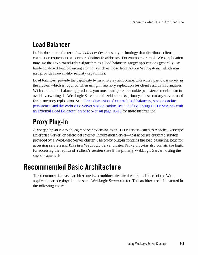
Recommended Bas ic A rch i tec tu re
Using WebLogic Server Clusters 9-3
Load BalancerIn this document, the term load balancer describes any technology that distributes client connection requests to one or more distinct IP addresses. For example, a simple Web application may use the DNS round-robin algorithm as a load balancer. Larger applications generally use hardware-based load balancing solutions such as those from Alteon WebSystems, which may also provide firewall-like security capabilities.
Load balancers provide the capability to associate a client connection with a particular server in the cluster, which is required when using in-memory replication for client session information. With certain load balancing products, you must configure the cookie persistence mechanism to avoid overwriting the WebLogic Server cookie which tracks primary and secondary servers used for in-memory replication. See “For a discussion of external load balancers, session cookie persistence, and the WebLogic Server session cookie, see “Load Balancing HTTP Sessions with an External Load Balancer” on page 5-2” on page 10-13 for more information.
Proxy Plug-InA proxy plug-in is a WebLogic Server extension to an HTTP server—such as Apache, Netscape Enterprise Server, or Microsoft Internet Information Server—that accesses clustered servlets provided by a WebLogic Server cluster. The proxy plug-in contains the load balancing logic for accessing servlets and JSPs in a WebLogic Server cluster. Proxy plug-ins also contain the logic for accessing the replica of a client’s session state if the primary WebLogic Server hosting the session state fails.
Recommended Basic ArchitectureThe recommended basic architecture is a combined tier architecture—all tiers of the Web application are deployed to the same WebLogic Server cluster. This architecture is illustrated in the following figure.
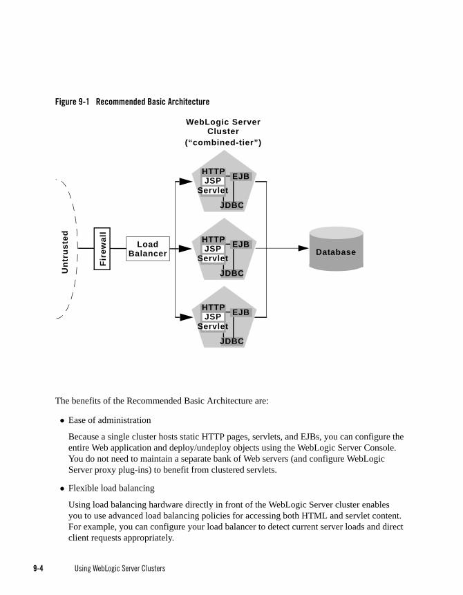
9-4 Using WebLogic Server Clusters
Figure 9-1 Recommended Basic Architecture
The benefits of the Recommended Basic Architecture are:
Ease of administration
Because a single cluster hosts static HTTP pages, servlets, and EJBs, you can configure the entire Web application and deploy/undeploy objects using the WebLogic Server Console. You do not need to maintain a separate bank of Web servers (and configure WebLogic Server proxy plug-ins) to benefit from clustered servlets.
Flexible load balancing
Using load balancing hardware directly in front of the WebLogic Server cluster enables you to use advanced load balancing policies for accessing both HTML and servlet content. For example, you can configure your load balancer to detect current server loads and direct client requests appropriately.
Database
JDBC
EJBHTTPJSP
Servlet
JDBC
EJBHTTPJSP
Servlet
JDBC
EJBHTTPJSP
Servlet
Fire
wal
l
WebLogic ServerCluster
Unt
rust
ed
LoadBalancer
(“combined-tier”)

Recommended Bas ic A rch i tec tu re
Using WebLogic Server Clusters 9-5
Robust security
Placing a firewall in front of your load balancing hardware enables you to set up a De-Militarized Zone (DMZ) for your web application using minimal firewall policies.
Optimal performance
The combined tier architecture offers the best performance for applications in which most or all of the servlets or JSPs in the presentation tier typically access objects in the object tier, such as EJBs or JDBC objects
Note: When using a third-party load balancer with in-memory session replication, you must ensure that the load balancer maintains a client’s connection to the WebLogic Server instance that hosts its primary session state (the point-of-contact server). For more information about load balancers, see “For a discussion of external load balancers, session cookie persistence, and the WebLogic Server session cookie, see “Load Balancing HTTP Sessions with an External Load Balancer” on page 5-2” on page 10-13.
When Not to Use a Combined Tier ArchitectureWhile a combined tier architecture, such as the Recommended Basic Architecture, meets the needs of many Web applications, it limits your ability to fully employ the load balancing and failover capabilities of a cluster. Load balancing and failover can be introduced only at the interfaces between Web application tiers, so, when tiers are deployed to a single cluster, you can only load balance between clients and the cluster.
Because most load balancing and failover occurs between clients and the cluster itself, a combined tier architecture meets the needs of most Web applications.
However, combined-tier clusters provide no opportunity for load balancing method calls to clustered EJBs. Because clustered objects are deployed on all WebLogic Server instances in the cluster, each object instance is available locally to each server. WebLogic Server optimizes method calls to clustered EJBs by always selecting the local object instance, rather than distributing requests to remote objects and incurring additional network overhead.
This collocation strategy is, in most cases, more efficient than load balancing each method request to a different server. However, if the processing load to individual servers becomes unbalanced, it may eventually become more efficient to submit method calls to remote objects rather than process methods locally.
To utilize load balancing for method calls to clustered EJBs, you must split the presentation and object tiers of the Web application onto separate physical clusters, as described in the following section.

9-6 Using WebLogic Server Clusters
Consider the frequency of invocations of the object tier by the presentation tier when deciding between a combined tier and multi-tier architecture. If presentation objects usually invoke the object tier, a combined tier architecture may offer better performance than a multi-tier architecture.
Recommended Multi-Tier ArchitectureThis section describes the Recommended Multi-Tier Architecture, in which different tiers of your application are deployed to different clusters.
The recommended multi-tier architecture uses two separate WebLogic Server clusters: one to serve static HTTP content and clustered servlets, and one to serve clustered EJBs. The multi-tier cluster is recommended for Web applications that:
Require load balancing for method calls to clustered EJBs.
Require more flexibility for balancing the load between servers that provide HTTP content and servers that provide clustered objects.
Require higher availability (fewer single points of failure).
Note: Consider the frequency of invocations from the presentation tier to the object tier when considering a multi-tier architecture. If presentation objects usually invoke the object tier, a combined tier architecture may offer better performance than a multi-tier architecture.
The following figure depicts the recommended multi-tier architecture.
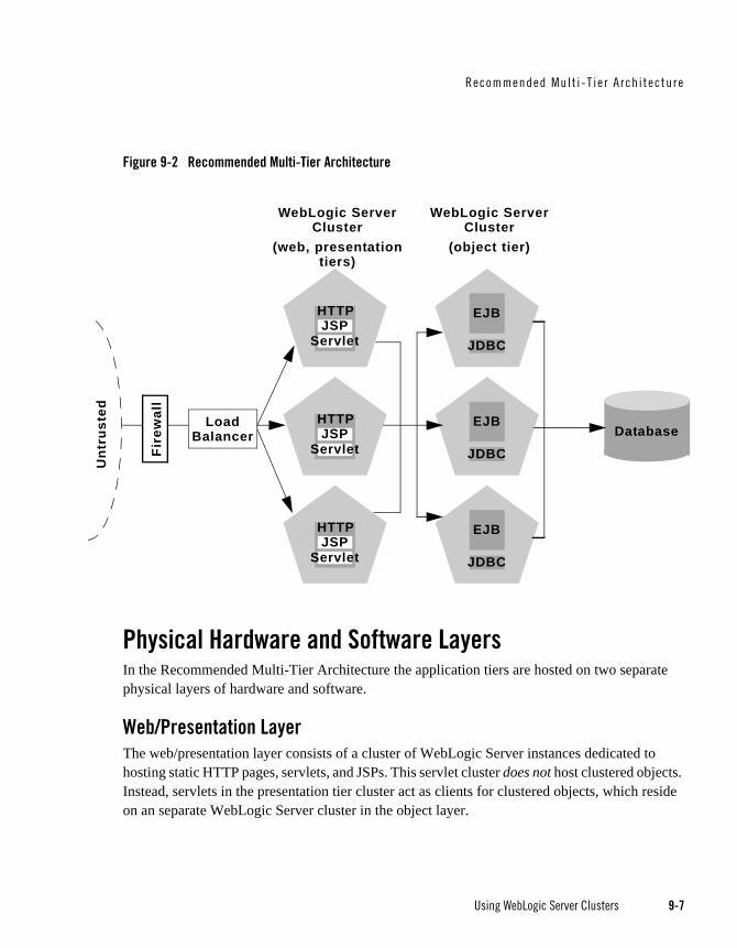
Recommended Mul t i -T ie r A rch i tec ture
Using WebLogic Server Clusters 9-7
Figure 9-2 Recommended Multi-Tier Architecture
Physical Hardware and Software LayersIn the Recommended Multi-Tier Architecture the application tiers are hosted on two separate physical layers of hardware and software.
Web/Presentation LayerThe web/presentation layer consists of a cluster of WebLogic Server instances dedicated to hosting static HTTP pages, servlets, and JSPs. This servlet cluster does not host clustered objects. Instead, servlets in the presentation tier cluster act as clients for clustered objects, which reside on an separate WebLogic Server cluster in the object layer.
Database
JDBC
EJB
WebLogic ServerCluster
JDBC
EJB
JDBC
EJB
Unt
rust
ed
HTTPJSP
Servlet
WebLogic ServerCluster
HTTPJSP
Servlet
HTTPJSP
Servlet
Fire
wal
l
LoadBalancer
(object tier)(web, presentationtiers)

9-8 Using WebLogic Server Clusters
Object LayerThe object layer consists of a cluster of WebLogic Server instances that hosts only clustered objects—EJBs and RMI objects as necessary for the web application. By hosting the object tier on a dedicated cluster, you lose the default collocation optimization for accessing clustered objects described in “Optimization for Collocated Objects” on page 5-12. However, you gain the ability to load balance on each method call to certain clustered objects, as described in the following section.
Benefits of Multi-Tier ArchitectureThe multi-tier architecture provides these advantages:
Load Balancing EJB Methods
By hosting servlets and EJBs on separate clusters, servlet method calls to EJBs can be load balanced across multiple servers. This process is described in detail in “Load Balancing Clustered Objects in a in Multi-Tier Architecture” on page 9-9.
Improved Server Load Balancing
Separating the presentation and object tiers onto separate clusters provides more options for distributing the load of the web application. For example, if the application accesses HTTP and servlet content more often than EJB content, you can use a large number of WebLogic Server instances in the presentation tier cluster to concentrate access to a smaller number of servers hosting EJBs.
Higher Availability
By utilizing additional WebLogic Server instances, the multi-tier architecture has fewer points of failure than the basic cluster architecture. For example, if a WebLogic Server that hosts EJBs fails, the HTTP- and servlet-hosting capacity of the Web application is not affected.
Improved Security Options
By separating the presentation and object tiers onto separate clusters, you can use a firewall policy that places only the servlet/JSP cluster in the DMZ. Servers hosting clustered objects can be further protected by denying direct access from untrusted clients. For more information, see “Security Options for Cluster Architectures” on page 9-17.

Recommended Mul t i -T ie r A rch i tec ture
Using WebLogic Server Clusters 9-9
Load Balancing Clustered Objects in a in Multi-Tier ArchitectureWebLogic Server’s collocation optimization for clustered objects, described in “Optimization for Collocated Objects” on page 5-12, relies on having a clustered object (the EJB or RMI class) hosted on the same server instance as the replica-aware stub that calls the object.
The net effect of isolating the object tier is that no client (HTTP client, Java client, or servlet) ever acquires a replica-aware stub on the same server that hosts the clustered object. Because of this, WebLogic Server cannot use its collocation optimization (described in “Optimization for Collocated Objects” on page 5-12), and servlet calls to clustered objects are automatically load balanced according to the logic contained in the replica-aware stub. The following figure depicts a client accessing a clustered EJB instance in the multi-tier architecture.
Figure 9-3 Load Balancing Objects in a Multi-Tier Architecture
Tracing the path of the client connection, you can see the implication of isolating the object tier onto separate hardware and software:
Database
Web/ServletCluster
ObjectCluster
EJB
EJB
EJB
Stu
b
JDBC
JDBC
JDBC
LoadBalancer
Clie
nt
HTTPJSP
Servlet
HTTPJSP
Servlet
HTTPJSP
Servlet

9-10 Using WebLogic Server Clusters
1. An HTTP client connects to one of several WebLogic Server instances in the web/servlet cluster, going through a load balancer to reach the initial server.
2. The client accesses a servlet hosted on the WebLogic Server cluster.
3. The servlet acts as a client to clustered objects required by the web application. In the example above, the servlet accesses a stateless session EJB.
The servlet looks up the EJB on the WebLogic Server cluster that hosts clustered objects. The servlet obtains a replica-aware stub for the bean, which lists the addresses of all servers that host the bean, as well as the load balancing logic for accessing bean replicas.
Note: EJB replica-aware stubs and EJB home load algorithms are specified using elements of the EJB deployment descriptor. See “weblogic-ejb-jar.xml Deployment Descriptor Reference” in Programming WebLogic Enterprise JavaBeans for more information.
4. When the servlet next accesses the EJB (for example, in response to another client), it uses the load-balancing logic present in the bean’s stub to locate a replica. In the example above, multiple method calls are directed using the round-robin algorithm for load balancing.
In this example, if the same WebLogic Server cluster hosted both servlets and EJBs (as in the Recommended Basic Architecture), WebLogic Server would not load balance requests for the EJB. Instead, the servlet would always invoke methods on the EJB replica hosted on the local server. Using the local EJB instance is more efficient than making remote method calls to an EJB on another server. However, the multi-tier architecture enables remote EJB access for applications that require load balancing for EJB method calls.
Configuration Considerations for Multi-Tier Architecture
IP Socket UsageBecause the multi-tier architecture provides load balancing for clustered object calls, the system generally utilizes more IP sockets than a combined-tier architecture. In particular, during peak socket usage, each WebLogic Server in the cluster that hosts servlets and JSPs may potentially use a maximum of:
One socket for replicating HTTP session states between primary and secondary servers, plus
One socket for each WebLogic Server in the EJB cluster, for accessing remote objects
For example, in Figure 9-2, each server in the servlet/JSP cluster could potentially open a maximum of five sockets. This maximum represents a worst-case scenario where primary and

Recommended Mul t i -T ie r A rch i tec ture
Using WebLogic Server Clusters 9-11
secondary session states are equally dispersed throughout the servlet cluster, and each server in the servlet cluster simultaneously accesses a remote object on each server in the object cluster. In most cases, the number of sockets actual sockets in use would be less than this maximum.
If you use a pure-Java sockets implementation with the multi-tier architecture, ensure that you configure enough socket reader threads to accommodate the maximum potential socket usage. For details, see “Configuring Reader Threads for Java Socket Implementation” on page 3-7.
Hardware Load BalancersBecause the multi-tier architecture uses a hardware load balancer, you must configure the load balancer to maintain a “sticky” connection to the client’s point-of-contact server if you use in-memory session state replication. For details, see “Configure Load Balancing Method for EJBs and RMIs” on page 10-12.
Limitations of Multi-Tier ArchitecturesThis section summarizes the limitations of multi-tier cluster architectures.
No Collocation OptimizationBecause the Recommended Multi-Tier Architecture cannot optimize object calls using the collocation strategy, the Web application incurs network overhead for all method calls to clustered objects. This overhead may be acceptable, however, if your Web application requires any of the benefits described in “Benefits of Multi-Tier Architecture” on page 9-8.
For example, if your Web clients make heavy use of servlets and JSPs but access a relatively small set of clustered objects, the multi-tier architecture enables you to concentrate the load of servlets and object appropriately. You may configure a servlet cluster of ten WebLogic Server instances and an object cluster of three WebLogic Server instances, while still fully utilizing each server’s processing power.
Firewall RestrictionsIf you place a firewall between the servlet cluster and object cluster in a multi-tier architecture, you must bind all servers in the object cluster to public DNS names, rather than IP addresses. Binding those servers with IP addresses can cause address translation problems and prevent the servlet cluster from accessing individual server instances.
If the internal and external DNS names of a WebLogic Server instance are not identical, use the ExternalDNSName attribute for the server instance to define the server's external DNS name. Outside the firewall the ExternalDNSName should translate to external IP address of the server.

9-12 Using WebLogic Server Clusters
Use of ExternalDNSName is required for configurations in which a firewall is performing Network Address Translation, unless clients are accessing WebLogic Server using t3 and the default channel. For instance, ExternalDNSName is required for configurations in which a firewall is performing Network Address Translation, and clients are accessing WebLogic Server using HTTP via a proxy plug-in.
Recommended Proxy ArchitecturesYou can configure WebLogic Server clusters to operate alongside existing Web servers. In such an architecture, a bank of Web servers provides static HTTP content for the Web application, using a WebLogic proxy plug-in or HttpClusterServlet to direct servlet and JSP requests to a cluster.
The following sections describe two alternative proxy architectures.
Two-Tier Proxy ArchitectureThe two-tier proxy architecture illustrated in the following figure is similar to the “Recommended Basic Architecture” on page 9-3, except that static HTTP servers are hosted on a bank of Web servers.

Recommended Proxy A rch i tec tu res
Using WebLogic Server Clusters 9-13
Figure 9-4 Two-Tier Proxy Architecture
Physical Hardware and Software LayersThe two-tier proxy architecture contains two physical layers of hardware and software.
Web LayerThe proxy architecture utilizes a layer of hardware and software dedicated to the task of providing the application’s web tier. This physical web layer can consist of one or more identically-configured machines that host one of the following application combinations:
WebLogic Server with the HttpClusterServlet
Apache with the WebLogic Server Apache proxy plug-in
Netscape Enterprise Server with the WebLogic Server NSAPI proxy plug-in
DMZ
Database
Clie
nts
JDBC
EJBJSPServlet
Servlet/ObjectCluster
Web Servers
HTTP Server
Proxy Plug-inFire
wal
l
HTTP Server
Proxy Plug-in
HTTP Server
Proxy Plug-inJDBC
EJBJSPServlet
JDBC
EJBJSPServlet
(web tier)(presentation,object tiers)

9-14 Using WebLogic Server Clusters
Microsoft Internet Information Server with the WebLogic Server Microsoft-IIS proxy plug-in
Regardless of which Web server software you select, keep in mind that the physical tier of Web servers should provide only static Web pages. Dynamic content—servlets and JSPs—are proxied via the proxy plug-in or HttpClusterServlet to a WebLogic Server cluster that hosts servlets and JSPs for the presentation tier.
Servlet/Object LayerThe recommended two-tier proxy architecture hosts the presentation and object tiers on a cluster of WebLogic Server instances. This cluster can be deployed either on a single machine or on multiple separate machines.
The Servlet/Object layer differs from the combined-tier cluster described in Recommended Basic Architecture in that it does not provide static HTTP content to application clients.
Multi-Tier Proxy ArchitectureYou can also use a bank of Web servers as the front-end to a pair of WebLogic Server clusters that host the presentation and object tiers. This architecture is shown in the following figure.

Recommended Proxy A rch i tec tu res
Using WebLogic Server Clusters 9-15
Figure 9-5 Multi-Tier Proxy Architecture
This architecture provides the same benefits (and the same limitations) as the Recommended Multi-Tier Architecture. It differs only insofar as the web tier is placed on a separate bank of Web servers that utilize WebLogic proxy plug-ins.
Proxy Architecture BenefitsUsing standalone Web servers and proxy plug-ins provides the following advantages:
Utilize Existing Hardware
Clie
nts
JSPServlet
ServletCluster
ObjectCluster
JSPServlet
JSPServlet
EJB
EJB
EJB
Fire
wal
l
Database
HTTP Server
Web Servers
Proxy Plug-in
HTTP Server
Proxy Plug-in
HTTP Server
Proxy Plug-in
(web tier)(presentation
tier)(object tier)

9-16 Using WebLogic Server Clusters
If you already have a Web application architecture that provides static HTTP content to clients, you can easily integrate existing Web servers with one or more WebLogic Server clusters to provide dynamic HTTP and clustered objects.
Familiar Firewall Policies
Using a Web server proxy at the front-end of your Web application enables you to use familiar firewall policies to define your DMZ. In general, you can continue placing the Web servers in your DMZ while disallowing direct connections to the remaining WebLogic Server clusters in the architecture. The figures above depict this DMZ policy.
Proxy Architecture LimitationsUsing standalone Web servers and proxy plug-ins limits your Web application in the following ways:
Additional administration
The Web servers in the proxy architecture must be configured using third-party utilities, and do not appear within the WebLogic Server administrative domain. You must also install and configure WebLogic proxy plug-ins to the Web servers in order to benefit from clustered servlet access and failover.
Limited Load Balancing Options
When you use proxy plug-ins or the HttpClusterServlet to access clustered servlets, the load balancing algorithm is limited to a simple round-robin strategy.
Proxy Plug-In Versus Load BalancerUsing a load balancer directly with a WebLogic Server cluster provides several benefits over proxying servlet requests. First, using WebLogic Server with a load balancer requires no additional administration for client setup—you do not need to set up and maintain a separate layer of HTTP servers, and you do not need to install and configure one or more proxy plug-ins. Removing the Web proxy layer also reduces the number of network connections required to access the cluster.
Using load balancing hardware provides more flexibility for defining load balancing algorithms that suit the capabilities of your system. You can use any load balancing strategy (for example, load-based policies) that your load balancing hardware supports. With proxy plug-ins or the HttpClusterServlet, you are limited to a simple round-robin algorithm for clustered servlet requests.

Secur i t y Opt i ons fo r C lus te r A rch i tec tu res
Using WebLogic Server Clusters 9-17
Note, however, that using a third-party load balancer may require additional configuration if you use in-memory session state replication. In this case, you must ensure that the load balancer maintains a “sticky” connection between the client and its point-of-contact server, so that the client accesses the primary session state information. When using proxy plug-ins, no special configuration is necessary because the proxy automatically maintains a sticky connection.
Security Options for Cluster ArchitecturesThe boundaries between physical hardware/software layers in the recommended configurations provide potential points for defining your Web application’s De-Militarized Zone (DMZ). However, not all boundaries can support a physical firewall, and certain boundaries can support only a subset of typical firewall policies.
The sections that follow describe several common ways of defining your DMZ to create varying levels of application security.
Basic Firewall for Proxy ArchitecturesThe basic firewall configuration uses a single firewall between untrusted clients and the Web server layer, and it can be used with either the Recommended Basic Architecture or Recommended Multi-Tier Architecture cluster architectures.

9-18 Using WebLogic Server Clusters
Figure 9-6 Basic Proxy with Firewall Architecture
In the above configuration, the single firewall can use any combination of policies (application-level restrictions, NAT, IP masquerading) to filter access to three HTTP servers. The most important role for the firewall is to deny direct access to any other servers in the system. In other words, the servlet layer, the object layer, and the database itself must not be accessible from untrusted clients.
Note that you can place the physical firewall either in front of or behind the Web servers in the DMZ. Placing the firewall in front of the Web servers simplifies your firewall policies, because you need only permit access to the web servers and deny access to all other systems.
Firewall Between Proxy Layer and ClusterIf you place a firewall between the proxy layer and the cluster, follow these configuration guidelines:
Database
Unt
rust
ed
JDBC
EJBJSPServlet
JDBC
EJBJSPServlet
JDBC
EJBJSPServlet
Servlet/ObjectCluster
HTTP Server
Web Layer
Proxy Plug-in
HTTP Server
Proxy Plug-in
HTTP Server
Proxy Plug-in
Fire
wal
l
DMZ

Secur i t y Opt i ons fo r C lus te r A rch i tec tu res
Using WebLogic Server Clusters 9-19
Bind to clustered server instances using publicly-listed DNS names, rather than IP addresses, to ensure that the proxy plug-ins can connect to each server in the cluster without address translation error that might otherwise occur, as described in “Firewall Considerations” on page 11-14.
If the internal and external DNS names of a clustered server instance are not identical, use the ExternalDNSName attribute for the server instance to define the its external DNS name. Outside the firewall the ExternalDNSName should translate to external IP address of the server instance.
Note: If the clustered servers segregate https and http traffic on a pair of custom channels, see “Channels, Clusters, and Firewalls” in Designing and Configuring WebLogic Server Environments.
DMZ with Basic Firewall ConfigurationsBy denying access to all but the Web server layer, the basic firewall configuration creates a small-footprint DMZ that includes only three Web servers. However, a more conservative DMZ definition might take into account the possibility that a malicious client may gain access to servers hosting the presentation and object tiers.
For example, assume that a hacker gains access to one of the machines hosting a Web server. Depending on the level of access, the hacker may then be able to gain information about the proxied servers that the Web server accesses for dynamic content.
If you choose to define your DMZ more conservatively, you can place additional firewalls using the information in “Additional Security for Shared Databases” on page 9-22.
Combining Firewall with Load BalancerIf you use load balancing hardware with a recommended cluster architecture, you must decide how to deploy the hardware in relationship to the basic firewall. Although many hardware solutions provide security features in addition to load balancing services, most sites rely on a firewall as the first line of defense for their Web applications. In general, firewalls provide the most well-tested and familiar security solution for restricting web traffic, and should be used in front of load balancing hardware, as shown below.

9-20 Using WebLogic Server Clusters
Figure 9-7 Basic Proxy with Firewall and Load Balancer Architecture
The above setup places the load balancer within the DMZ along with the web tier. Using a firewall in this configuration can simplify security policy administration, because the firewall need only limit access to the load balancer. This setup can also simplify administration for sites that support internal clients to the Web application, as described below.
Expanding the Firewall for Internal ClientsIf you support internal clients that require direct access to your Web application (for example, remote machines that run proprietary Java applications), you can expand the basic firewall configuration to allow restricted access to the presentation tier. The way in which you expand access to the application depends on whether you treat the remote clients as trusted or untrusted connections.
If you use a Virtual Private Network (VPN) to support remote clients, the clients may be treated as trusted connections and can connect directly to the presentation tier going through a firewall. This configuration is shown below.
Database
Unt
rust
ed
HTTP Server
Web Layer
Proxy Plug-in
HTTP Server
Proxy Plug-in
HTTP Server
Proxy Plug-in
Firewall
HTTP Server
Proxy Plug-inLoadBalancer
DM
Z
JDBC
EJBJSPServlet
JDBC
EJBJSPServlet
JDBC
EJBJSPServlet
Servlet/ObjectCluster
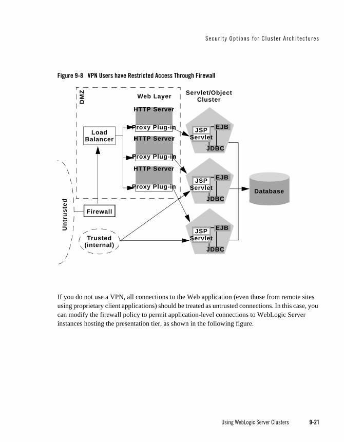
Secur i t y Opt i ons fo r C lus te r A rch i tec tu res
Using WebLogic Server Clusters 9-21
Figure 9-8 VPN Users have Restricted Access Through Firewall
If you do not use a VPN, all connections to the Web application (even those from remote sites using proprietary client applications) should be treated as untrusted connections. In this case, you can modify the firewall policy to permit application-level connections to WebLogic Server instances hosting the presentation tier, as shown in the following figure.
Database
Unt
rust
ed
HTTP Server
Web Layer
Proxy Plug-in
HTTP Server
Proxy Plug-in
HTTP Server
Proxy Plug-in
Firewall
HTTP Server
Proxy Plug-in
LoadBalancer
DM
Z
JDBC
EJBJSPServlet
JDBC
EJBJSPServlet
JDBC
EJBJSPServlet
Servlet/ObjectCluster
Trusted(internal)
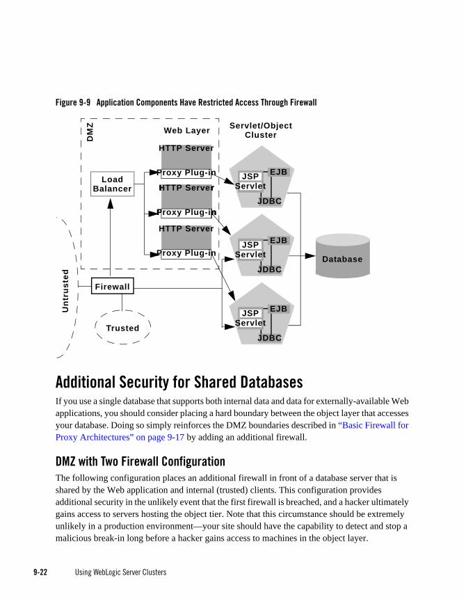
9-22 Using WebLogic Server Clusters
Figure 9-9 Application Components Have Restricted Access Through Firewall
Additional Security for Shared DatabasesIf you use a single database that supports both internal data and data for externally-available Web applications, you should consider placing a hard boundary between the object layer that accesses your database. Doing so simply reinforces the DMZ boundaries described in “Basic Firewall for Proxy Architectures” on page 9-17 by adding an additional firewall.
DMZ with Two Firewall ConfigurationThe following configuration places an additional firewall in front of a database server that is shared by the Web application and internal (trusted) clients. This configuration provides additional security in the unlikely event that the first firewall is breached, and a hacker ultimately gains access to servers hosting the object tier. Note that this circumstance should be extremely unlikely in a production environment—your site should have the capability to detect and stop a malicious break-in long before a hacker gains access to machines in the object layer.
Database
Unt
rust
ed
HTTP Server
Web Layer
Proxy Plug-in
HTTP Server
Proxy Plug-in
HTTP Server
Proxy Plug-in
Firewall
HTTP Server
Proxy Plug-in
LoadBalancer
DM
Z
JDBC
EJBJSPServlet
JDBC
EJBJSPServlet
JDBC
EJBJSPServlet
Servlet/ObjectCluster
Trusted

Secur i t y Opt i ons fo r C lus te r A rch i tec tu res
Using WebLogic Server Clusters 9-23
Figure 9-10 DMZ with Two Firewalls Architecture
In the above configuration, the boundary between the object tier and the database is hardened using an additional firewall. The firewall maintains a strict application-level policy that denies access to all connections except JDBC connections from WebLogic Servers hosting the object tier.
Database
Unt
rust
ed
JDBC
EJBJSPServlet
JDBC
EJBJSPServlet
JDBC
EJBJSPServlet
Servlet/ObjectCluster
HTTP Server
Web Layer
Proxy Plug-in
HTTP Server
Proxy Plug-in
HTTP Server
Proxy Plug-in
Fire
wal
l
DMZ
Firewall
Trusted Clients

9-24 Using WebLogic Server Clusters

Using WebLogic Server Clusters 10-1
C H A P T E R 10
Setting up WebLogic Clusters
The following sections contain guidelines and instructions for configuring a WebLogic Server cluster:
“Before You Start” on page 10-1
“Cluster Implementation Procedures” on page 10-8
Before You StartThis section summarizes prerequisite tasks and information for setting up a WebLogic Server Cluster.
Understand the Configuration ProcessThe information in this section will be most useful to you if you have a basic understanding of the cluster configuration process and how configuration tasks are accomplished.
For information about the configuration facilities available in WebLogic Server and the tasks they support, see “Understanding Cluster Configuration” on page 4-1.
Determine Your Cluster ArchitectureDetermine what cluster architecture best suits your needs. Key architectural decisions include:
Should you combine all application tiers in a single cluster or segment your application tiers in separate clusters?

10-2 Using WebLogic Server Clusters
How will you balance the load among server instances in your cluster? Will you:
– Use basic WebLogic Server load balancing,
– Implement a third-party load balancer, or
– Deploy the Web tier of your application on one or more secondary HTTP servers, and proxy requests to it?
Should you define your Web applications De-Militarized Zone (DMZ) with one or more firewalls?
To guide these decisions, see “Cluster Architectures” on page 9-1, and “Load Balancing in a Cluster” on page 5-1.
The architecture you choose affects how you set up your cluster. The cluster architecture may also require that you install or configure other resources, such as load balancers, HTTP servers, and proxy plug-ins.
Consider Your Network and Security TopologiesYour security requirements form the basis for designing the appropriate security topology. For a discussion of several alternative architectures that provide varying levels of application security, see “Security Options for Cluster Architectures” on page 9-17.
Notes: Some network topologies can interfere with multicast communication. If you are deploying a cluster across a WAN, see “If Your Cluster Spans Multiple Subnets In a WAN” on page 3-3.
Avoid deploying server instances in a cluster across a firewall. For a discussion of the impact of tunneling multicast traffic through a firewall, see “Firewalls Can Break Multicast Communication” on page 3-3.
Choose Machines for the Cluster InstallationIdentify the machine or machines where you plan to install WebLogic Server—throughout this section we refer to such machines as “hosts”—and ensure that they have the resources required. WebLogic Server allows you to set up a cluster on a single, non-multihomed machine. This new capability is useful for demonstration or development environments.
Do not install WebLogic Server on machines that have dynamically assigned IP addresses.

Befo re You S ta r t
Using WebLogic Server Clusters 10-3
WebLogic Server Instances on Multi-CPU machinesBEA WebLogic Server has no built-in limit for the number of server instances that can reside in a cluster. Large, multi-processor servers such as Sun Microsystems, Inc. Sun Enterprise 10000 can host very large clusters or multiple clusters.
In most cases, WebLogic Server clusters scale best when deployed with one WebLogic Server instance for every two CPUs. However, as with all capacity planning, you should test the actual deployment with your target Web applications to determine the optimal number and distribution of server instances. See “Performance Considerations for Multi-CPU Machines” in BEA WebLogic Server Performance and Tuning for additional information.
Check Host Machines’ Socket Reader ImplementationFor best socket performance, configure the WebLogic Server host machine to use the native socket reader implementation for your operating system, rather than the pure-Java implementation. To understand why, and for instructions for configuring native sockets or optimizing pure-Java socket communications, see “Peer-to-Peer Communication Using IP Sockets” on page 3-5.
Setting Up a Cluster on a Disconnected Windows Machine
If you want to demonstrate a WebLogic Server cluster on a single, disconnected Windows machine, you must force Windows to load the TCP/IP stack. By default, Windows does not load the TCP/IP stack if it does not detect a physical network connection.
To force Windows to load the TCP/IP stack, disable the Windows media sensing feature using the instructions in “How to Disable Media Sense for TCP/IP in Windows” at http://support.microsoft.com/default.aspx?scid=kb;en-us;239924.
Identify Names and AddressesDuring the cluster configuration process, you supply addressing information—IP addresses or DNS names, and port numbers—for the server instances in the cluster.
For information on intra-cluster communication, and how it enables load balancing and failover, see “WebLogic Server Communication In a Cluster” on page 3-1.
When you set up your cluster, you must provide location information for:
Administration Server

10-4 Using WebLogic Server Clusters
Managed Servers
Multicast location
Read the sections that follow for an explanation of the information you must provide, and factors that influence the method you use to identify resources.
Avoiding Listen Address ProblemsAs you configure a cluster, you can specify address information using either IP addresses or DNS names.
DNS Names or IP Addresses?Consider the purpose of the cluster when deciding whether to use DNS names or IP addresses. For production environments, the use of DNS names is generally recommended. The use of IP addresses can result in translation errors if:
Clients will connect to the cluster through a firewall, or
You have a firewall between the presentation and object tiers, for example, you have a servlet cluster and EJB cluster with a firewall in between, as described in the recommended multi-tier cluster.
You can avoid translation errors by binding the address of an individual server instance to a DNS name. Make sure that a server instance’s DNS name is identical on each side of firewalls in your environment, and do not use a DNS name that is also the name of an NT system on your network.
For more information about using DNS names instead of IP addresses, see “Firewall Considerations” on page 11-14.
When Internal and External DNS Names VaryIf the internal and external DNS names of a WebLogic Server instance are not identical, use the ExternalDNSName attribute for the server instance to define the server's external DNS name. Outside the firewall the ExternalDNSName should translate to external IP address of the server. If clients are accessing WebLogic Server over the default channel and T3, do not set the ExternalDNSName attribute, even if the internal and external DNS names of a WebLogic Server instance are not identical.
Localhost ConsiderationsIf you identify a server instance’s Listen Address as localhost, non-local processes will not be able to connect to the server instance. Only processes on the machine that hosts the server
Befo re You S ta r t
Using WebLogic Server Clusters 10-5
instance will be able to connect to the server instance. If the server instance must be accessible as localhost (for instance, if you have administrative scripts that connect to localhost), and must also be accessible by remote processes, leave the Listen Address blank. The server instance will determine the address of the machine and listen on it.
Assigning Names to WebLogic Server ResourcesMake sure that each configurable resource in your WebLogic Server environment has a unique name. Each, domain, server, machine, cluster, JDBC data source, virtual host, or other resource must have a unique name.
Administration Server Address and PortIdentify the DNS name or IP address and Listen Port of the Administration Server you will use for the cluster.
The Administration Server is the WebLogic Server instance used to configure and manage all the Managed Servers in its domain. When you start a Managed Server, you identify the host and port of its Administration Server.
Managed Server Addresses and Listen PortsIdentify the DNS name or IP address of each Managed Server planned for your cluster.
Each Managed Server in a cluster must have a unique combination of address and Listen Port number. Clustered server instances on a single non-multihomed machine can have the same address, but must use a different Listen Port.
Cluster Multicast Address and PortIdentify the address and port you will dedicate to multicast communications for your cluster. A multicast address is an IP address between 224.0.0.0 and 239.255.255.255.
Note: The default multicast value used by WebLogic Server is 239.192.0.0. You should not use any multicast address with the value x.0.0.1.
Server instances in a cluster communicate with each other using multicast—they use multicast to announce their services, and to issue periodic heartbeats that indicate continued availability.
The multicast address for a cluster should not be used for any purpose other than cluster communications. If the machine where the cluster multicast address exists hosts or is accessed by cluster-external programs that use multicast communication, make sure that those multicast communications use a different port than the cluster multicast port.

10-6 Using WebLogic Server Clusters
Multicast and Multiple Clusters Multiple clusters on a network may share a multicast address and multicast port combination if necessary.
Multicast and Multi-Tier ClustersIf you are setting up the Recommended Multi-Tier Architecture, described in Chapter 9, “Cluster Architectures,” with a firewall between the clusters, you will need two dedicated multicast addresses: one for the presentation (servlet) cluster and one for the object cluster. Using two multicast addresses ensures that the firewall does not interfere with cluster communication.
Cluster AddressIn WebLogic Server cluster, the cluster address is used in entity and stateless beans to construct the host name portion of request URLs.
You can explicitly define the cluster address when you configure the a cluster; otherwise, WebLogic Server dynamically generates the cluster address for each new request. Allowing WebLogic Server to dynamically generate the cluster address is simplest, in terms of system administration, and is suitable for both development and production environments.
Dynamic Cluster AddressIf you do not explicitly define a cluster address when you configure a cluster, when a clustered server instance receives a remote request, WebLogic Server generates the cluster address, in the form:
listenaddress1:listenport1,listenaddress2:listenport2;listenaddress3:
listenport3
Each listen address:listen port combination in the cluster address corresponds to Managed Server and network channel that received the request.
If the request was received on the Managed Server’s default channel, the listen address:listen port combinations in the cluster address reflect the ListenAddress and ListenPort values from the associated ServerMBean and SSLMBean instances. For more information, see “The Default Network Channel” in Configuring WebLogic Server Environments.
If the request was received on a custom network channel, the listen address:listen port in the cluster address reflect the ListenAddress and ListenPort values from NetworkAccessPointMBean that defines the channel. For more information about
Befo re You S ta r t
Using WebLogic Server Clusters 10-7
network channels in a cluster, see “Configuring Network Channels For a Cluster” in Configuring WebLogic Server Environments.
The number of ListenAddress:ListenPort combinations included in the cluster address is governed by the value of the NumberOfServersInClusterAddress attribute on the ClusterMBean, which is 3 by default.
You can modify the value of NumberOfServersInClusterAddress on the Environments—>Clusters—>ClusterName->Configuration->General page of the Administration Console.
If there are fewer Managed Servers available in the cluster than the value of NumberOfServersInClusterAddress, the dynamically generated cluster address contains a ListenAddress:ListenPort combination for each of the running Managed Servers.
If there are more Managed Servers available in the cluster than the value of NumberOfServersInClusterAddress, WebLogic Server randomly selects a subset of the available instances—equal to the value of NumberOfServersInClusterAddress—and uses the ListenAddress:ListenPort combination for those instances to form the cluster address.
The order in which the ListenAddress:ListenPort combinations appear in the cluster address is random—from request to request, the order will vary.
Explicitly Defining Cluster Address for Production EnvironmentsIf you explicitly define a cluster address for a cluster in a production environment, specify the cluster address as a DNS name that maps to the IP addresses or DNS names of each WebLogic Server instance in the cluster.
If you define the cluster address as a DNS name, the Listen Ports for the cluster members are not specified in the cluster address—it is assumed that each Managed Server in the cluster has the same Listen Port number. Because each server instance in a cluster must have a unique combination of address and Listen Port, if a cluster address is a DNS name, each server instance in the cluster must have:
a unique address and
the same Listen Port number
When clients obtain an initial JNDI context by supplying the cluster DNS name, weblogic.jndi.WLInitialContextFactory obtains the list of all addresses that are mapped to the DNS name. This list is cached by WebLogic Server instances, and new initial context requests are fulfilled using addresses in the cached list with a round-robin algorithm. If a server

10-8 Using WebLogic Server Clusters
instance in the cached list is unavailable, it is removed from the list. The address list is refreshed from the DNS service only if the server instance is unable to reach any address in its cache.
Using a cached list of addresses avoids certain problems with relying on DNS round-robin alone. For example, DNS round-robin continues using all addresses that have been mapped to the domain name, regardless of whether or not the addresses are reachable. By caching the address list, WebLogic Server can remove addresses that are unreachable, so that connection failures aren't repeated with new initial context requests.
Note: The Administration Server should not participate in a cluster. Ensure that the Administration Server's IP address is not included in the cluster-wide DNS name. For more information, see “Administration Server Considerations” on page 11-14.
Explicitly Defining Cluster Address for Development and Test EnvironmentsIf you explicitly define a cluster address for use in development environments, you can use a cluster DNS name for the cluster address, as described in the previous section.
Alternatively, you can define the cluster address as a list that contains the DNS name (or IP address) and Listen Port of each Managed Server in the cluster, as shown in the examples below:
DNSName1:port1,DNSName1:port2,DNSName1:port3
IPaddress1:port1,IPaddress2:port2;IPaddress3:port3
Note that each cluster member has a unique address and port combination.
Explicitly Defining Cluster Address for Single, Multihomed MachineIf your cluster runs on a single, multihomed machine, and each server instance in the cluster uses a different IP address, define the cluster address using a DNS name that maps to the IP addresses of the server instances in the cluster. If you define the cluster address as a DNS name, specify the same Listen Port number for each of the Managed Servers in the cluster.
Cluster Implementation ProceduresThis section describes how to get a clustered application up and running, from installation of WebLogic Server through initial deployment of application components.

Cluste r Implementat ion P rocedures
Using WebLogic Server Clusters 10-9
Configuration RoadmapThis section lists typical cluster implementation tasks, and highlights key configuration considerations. The exact process you follow is driven by the unique characteristics of your environment and the nature of your application. These tasks are described:
1. “Install WebLogic Server” on page 10-9
2. “Create a Clustered Domain” on page 10-10
3. “Configure Node Manager” on page 10-12
4. “Configure Load Balancing Method for EJBs and RMIs” on page 10-12
5. “Configure Server Affinity for Distributed JMS Destinations” on page 10-13
6. “Configuring Load Balancers that Support Passive Cookie Persistence” on page 10-13
7. “Configure Proxy Plug-Ins” on page 10-14
8. “Configure Replication Groups” on page 10-22
9. “Configure Migratable Targets for Pinned Services” on page 10-23
10. “Configure Clustered JDBC” on page 10-24
11. “Package Applications for Deployment” on page 10-25
12. “Deploy Applications” on page 10-25
13. “Deploying, Activating, and Migrating Migratable Services” on page 10-27
14. “Configure In-Memory HTTP Replication” on page 10-30
15. “Additional Configuration Topics” on page 10-30
Not every step is required for every cluster implementation. Additional steps may be necessary in some cases.
Install WebLogic ServerIf you have not already done so, install WebLogic Server. For instructions, see Installing WebLogic Server.
If the cluster will run on a single machine, do a single installation of WebLogic Server under the /bea directory to use for all clustered instances.
10-10 Using WebLogic Server Clusters
For remote, networked machines, install the same version of WebLogic Server on each machine. Each machine:
– Must have permanently assigned, static IP addresses. You cannot use dynamically-assigned IP addresses in a clustering environment.
– Must be accessible to clients. If the server instances are behind a firewall and the clients are in front of the firewall, each server instance must have a public IP address that can be reached by the clients.
– Must be located on the same local area network (LAN) and must be reachable via IP multicast.
Note: Do not use a shared filesystem and a single installation to run multiple WebLogic Server instances on separate machines. Using a shared filesystem introduces a single point of contention for the cluster. All server instances must compete to access the filesystem (and possibly to write individual log files). Moreover, should the shared filesystem fail, you might be unable to start clustered server instances.
Create a Clustered DomainThe are multiple methods of creating a clustered domain. For a list, see “Methods of Configuring Clusters” on page 4-8.
For instructions to create a cluster using the:
Configuration Wizard, first see “Creating a New WebLogic Domain” in Creating WebLogic Domains Using the Configuration Wizard for instructions on creating the domain, and then “Customizing your Domain” for instructions on configuring a cluster.
Administration Console, see Create and configure clusters in Administration Console Online Help.
Starting a WebLogic Server ClusterThere are multiple methods of starting a cluster—available options include the command line interface, scripts that contain the necessary commands, and Node Manager.
Note: Node Manager eases the process of starting servers, and restarting them after failure.
To use Node Manager, you must first configure a Node Manager process on each machine that hosts Managed Servers in the cluster. See “Configure Node Manager” on page 10-12.
Regardless of the method you use to start a cluster, start the Administration Server first, then start the Managed Servers in the cluster.

Cluste r Implementat ion P rocedures
Using WebLogic Server Clusters 10-11
Follow the instructions below to start the cluster from a command shell. Note that each server instance is started in a separate command shell.
1. Open a command shell.
2. Change directory to the domain directory that you created with the Configuration Wizard.
3. Type this command to start the Administration Server:
StartWebLogic
4. Enter the user name for the domain at the “Enter username to boot WebLogic Server” prompt.
5. Enter the password for the domain at the “Enter password to boot WebLogic Server” prompt.
The command shell displays messages that report the status of the startup process.
6. Open another command shell so that you can start a Managed Server.
7. Change directory to the domain directory that you created with the Configuration Wizard.
8. Type this command
StartManagedWebLogic server_name address:port
where:
server_name is the name of the Managed Server you wish to start
address is the IP address or DNS name for the Administration Server for the domain
port is the listen port for the Administration Server for the domain
9. Enter the user name for the domain at the “Enter username to boot WebLogic Server” prompt.
10. Enter the password for the domain at the “Enter password to boot WebLogic Server” prompt.
The command shell displays messages that report the status of the startup process.
Note: Note: After you start a Managed Server, it listens for heartbeats from other running server instances in the cluster. The Managed Server builds its local copy of the cluster-wide JNDI tree, as described in “How WebLogic Server Updates the JNDI Tree” on page 3-14, and displays status messages when it has synchronized with each running Managed Server in the cluster. The synchronization process can take a minute or so.
11. To start another server instance in the cluster, return to step 6 Continue through step 10

10-12 Using WebLogic Server Clusters
12. When you have started all Managed Servers in the cluster, the cluster startup process is complete.
Configure Node ManagerNode Manager is a standalone Java program provided with WebLogic Server that is useful for starting a Managed Server that resides on a different machine than its Administration Server. Node Manager also provides features that help increase the availability of Managed Servers in your cluster. For more information, and for instructions to configure and use Node Manager, see Using Node Manager to Control Servers in Designing and Configuring WebLogic Server Environments.
Configure Load Balancing Method for EJBs and RMIs Follow the instructions in this section to select the load balancing algorithm for EJBs and RMI objects.
Unless you explicitly specify otherwise, WebLogic Server uses the round-robin algorithm as the default load balancing strategy for clustered object stubs. To understand alternative load balancing algorithms, see “Load Balancing for EJBs and RMI Objects” on page 5-4. To change the default load balancing algorithm:
1. Open the WebLogic Server Console.
2. Select the Environments—>Clusters node.
3. Click on the name of your cluster in the table.
4. If you have not already done so, click the Lock & Edit button in the top left corner of the console.
5. Enter the desired load balancing algorithm in the Default Load Algorithm field.
6. Click the Advanced link.
7. Enter the desired value in the Service Age Threshold field
8. Click Save to save your changes.
9. Click the Activate Changes button in the top left corner once you are ready to activate your changes.

Cluste r Implementat ion P rocedures
Using WebLogic Server Clusters 10-13
Specifying a Timeout Value For RMIsYou can enable a timeout option when making calls to the ReplicationManager by setting the ReplicationTimeoutEnabled in the ClusterMBean to true.
The timeout value is equal to the multicast heartbeat timeout. Although you can customize the multicast timeout value, the ReplicationManager timeout cannot be changed. This restriction exists because the ReplicationManager timeout does not affect cluster membership. A missing multicast heartbeat causes the member to be removed from the cluster and the timed out ReplicationManager call will choose a new secondary server to connect to.
Note: It is possible that a cluster member will continue to send multicast heartbeats, but will be unable to process replication requests. This could potentially cause an uneven distribution of secondary servers. When this situation occurs, a warning message is recorded in the server logs.
Configure Server Affinity for Distributed JMS DestinationsTo understand the server affinity support provided by WebLogic Server for JMS, see “Load Balancing for JMS” on page 5-14.
Configuring Load Balancers that Support Passive Cookie PersistenceLoad balancers that support passive cookie persistence can use information from the WebLogic Server session cookie to associate a client with the WebLogic Server instance that hosts the session. The session cookie contains a string that the load balancer uses to identify the primary server instance for the session.
For a discussion of external load balancers, session cookie persistence, and the WebLogic Server session cookie, see “Load Balancing HTTP Sessions with an External Load Balancer” on page 5-2
To configure the load balancer to work with your cluster, use the facilities of the load balancer to define the offset and length of the string constant.
Assuming that the Session ID portion of the session cookie is the default length of 52 bytes, on the load balancer, set:
string offset to 53 bytes, the default Random Session ID length plus 1 byte for the delimiter character.

10-14 Using WebLogic Server Clusters
string length to 10 bytes
If your application or environmental requirements dictate that you change the length of the Random Session ID from its default value of 52 bytes, set the string offset on the load balancer accordingly. The string offset must equal the length of the Session ID plus 1 byte for the delimiter character.
Notes: For vendor-specific instructions for configuring Big-IP load balancers, see Appendix B, “Configuring BIG-IP™ Hardware with Clusters.”
Configure Proxy Plug-Ins Refer to the instructions in this section if you wish to load balance servlets and JSPs using a proxy plug-in. A proxy plug-in proxies requests from a web server to WebLogic Server instances in a cluster, and provides load balancing and failover for the proxied HTTP requests.
For information about load balancing using proxy plug-ins, see “Load Balancing with a Proxy Plug-in” on page 5-2. For information about connection and failover using proxy plug-ins, see “Replication and Failover for Servlets and JSPs” on page 6-2, and “Accessing Clustered Servlets and JSPs Using a Proxy” on page 6-9.
If you use WebLogic Server as a web server, set up HttpClusterServlet using the instructions in “Set Up the HttpClusterServlet” on page 10-14.
If you use a supported third-party web server, set up a product-specific plug-in (for a list of supported web servers, see “Load Balancing with a Proxy Plug-in” on page 5-2.), follow the instructions in Using WebLogic Server with Plug-ins.
Note: Each web server that proxies requests to a cluster must have an identically configured plug-in.
Set Up the HttpClusterServletTo use the HTTP cluster servlet, configure it as the default web application on your proxy server machine, as described in the steps below. For an introduction to web applications, see “Overview of Web Applications” in Developing Web Applications for WebLogic Server.
1. If you have not already done so, configure a separate, non-clustered Managed Server to host the HTTP Cluster Servlet.
2. Create the web.xml deployment descriptor file for the servlet. This file must reside in the \WEB-INF subdirectory of the web application directory. A sample deployment descriptor for the proxy servlet is provided in “Sample web.xml” on page 10-16. For more information on

Cluste r Implementat ion P rocedures
Using WebLogic Server Clusters 10-15
web.xml, see “Understanding Web Applications, Servlets, and JSPs” in Developing Web Applications, Servlets, and JSPs for WebLogic Server.
a. Define the name and class for the servlet in the <servlet> element in web.xml. The servlet name is HttpClusterServlet. The servlet class is weblogic.servlet.proxy.HttpClusterServlet.
b. Identify the clustered server instances to which the proxy servlet will direct requests in the <servlet> element in web.xml, by defining the WebLogicCluster parameter.
c. Optionally, define the following <KeyStore> initialization parameters to use two-way SSL with your own identity certificate and key. If no <KeyStore> is specified in the deployment descriptor, the proxy will assume one-way SSL.
• <KeyStore> – The key store location in your Web application.
• <KeyStoreType> – The key store type. If it is not defined, the default type will be used instead.
• <PrivateKeyAlias> – The private key alias.
• <KeyStorePasswordProperties> – A property file in your Web application that defines encrypted passwords to access the key store and private key alias. The file contents looks like this: KeyStorePassword={3DES}i4+50LCKenQO8BBvlsXTrg\=\=PrivateKeyPassword={3DES}a4TcG4mtVVBRKtZwH3p7yA\=\=
You must use the weblogic.security.Encrypt command-line utility to encrypt the password. For more information on the Encrypt utility, as well as the CertGen, and der2pem utilities, see Using the WebLogic Server Java Utilities in the WebLogic Server Command Reference.
d. Create <servlet-mapping> stanzas to specify the requests that the servlet will proxy to the cluster, using the <url-pattern> element to identify specific file extensions, for example *.jsp, or *.html. Define each pattern in a separate <servlet-mapping> stanza.
You can set the <url-pattern> to “/” to proxy any request that cannot be resolved by WebLogic Server to the remote server instance. If you do so, you must also specifically map the following extensions: *.jsp, *.html, and *.html, to proxy files ending with those extensions. For an example, see “Sample web.xml” on page 10-16.

10-16 Using WebLogic Server Clusters
e. Define, as appropriate, any additional parameters. See Table for a list of key parameters. See “Parameters for Web Server Plug-ins” in Using WebLogic Server with Plug-ins for a complete list. Follow the syntax instructions in “Proxy Servlet Deployment Parameters” on page 10-18.
3. Create the weblogic.xml deployment descriptor file for the servlet. This file must reside in the \WEB-INF subdirectory of the web application directory.
Assign the proxy servlet as the default web application for the Managed Server on the proxy machine by setting the <context-root> element to a forward slash character (/) in the <weblogic-web-app> stanza. For an example, see “Sample weblogic.xml” on page 10-18.
4. In the Administration Console, deploy the servlet to the Managed Server on your proxy server machine. For instructions, see “Deploying a New Web Application” in Administration Console Online Help.
Sample web.xml
This section contains a sample deployment descriptor file (web.xml) for HttpClusterServlet.
web.xml defines parameters that specify the location and behavior of the proxy servlet: both versions of the servlet:
The DOCTYPE stanza specifies the DTD used by WebLogic Server to validate web.xml.
The servlet stanza:
Specifies the location of the proxy plug-in servlet class. The file is located in the weblogic.jar in your WL_HOME/server/lib directory. You do not have to specify the servlet’s full directory path in web.xml because weblogic.jar is put in your CLASSPATH when you start WebLogic Server.
Identifies the host name(either DNS name or IP address) and listen port of each Managed Servers in the cluster, using the WebLogicCluster parameter.
Identifies the key store initialization parameters to use two-way SSL with your own identity certificate and key.
The three servlet-mapping stanzas specify that the servlet will proxy URLs that end in '/', 'htm', 'html', or 'jsp' to the cluster.
For parameter definitions see “Proxy Servlet Deployment Parameters” on page 10-18.<!DOCTYPE web-app PUBLIC "-//Sun Microsystems, Inc.//DTD Web Application
2.3//EN" "http://java.sun.com/dtd/web-app_2_3.dtd";>

Cluste r Implementat ion P rocedures
Using WebLogic Server Clusters 10-17
<web-app>
<servlet><servlet-name>HttpClusterServlet</servlet-name> <servlet-class>
weblogic.servlet.proxy.HttpClusterServlet</servlet-class>
<init-param><param-name>WebLogicCluster</param-name><param-value>hostname1:7736|hostname2:7736|hostname:7736</param-value>
</init-param>
<init-param>
<param-name>KeyStore</param-name>
<param-value>/mykeystore</param-value>
</init-param>
<init-param>
<param-name>KeyStoreType</param-name>
<param-value>jks</param-value>
</init-param>
<init-param>
<param-name>PrivateKeyAlias</param-name>
<param-value>passalias</param-value>
</init-param>
<init-param>
<param-name>KeyStorePasswordProperties</param-name>
<param-value>mykeystore.properties</param-value>
</init-param>
</servlet>
<servlet-mapping><servlet-name>HttpClusterServlet</servlet-name><url-pattern>/</url-pattern>
</servlet-mapping>
<servlet-mapping><servlet-name>HttpClusterServlet</servlet-name> <url-pattern>*.jsp</url-pattern>
</servlet-mapping>

10-18 Using WebLogic Server Clusters
<servlet-mapping><servlet-name>HttpClusterServlet</servlet-name> <url-pattern>*.htm</url-pattern>
</servlet-mapping>
<servlet-mapping><servlet-name>HttpClusterServlet</servlet-name> <url-pattern>*.html</url-pattern>
</servlet-mapping>
</web-app>
Sample weblogic.xmlThis section contains a sample weblogic.xml file. The <context-root> deployment parameter is set to "/". This makes the proxy servlet the default web application for the proxy server.
<!DOCTYPE weblogic-web-app PUBLIC "-//BEA Systems, Inc.//DTD Web Application 9.1//EN" "http://www.bea.com/servers/wls810/dtd/weblogic810-web-jar.dtd">
<weblogic-web-app><context-root>/</context-root>
</weblogic-web-app>
Proxy Servlet Deployment Parameters
Key parameters for configuring the behavior of the proxy servlet in web.xml are listed in Table 10-1.
The parameters for the proxy servlet are the same as those used to configure WebLogic Server plug-ins for Apache, Microsoft, and Netscape web servers. For a complete list of parameters for configuring the proxy servlet and the plug-ins for third-part web servers see “Parameters for Web Server Plug-ins” in Using WebLogic Server with Plug-ins.
The syntax for specifying the parameters, and the file where they are specified, is different for the proxy servlet and for each of the plug-ins.
For the proxy servlet, specify the parameters in web.xml, each in its own <init-param> stanza within the <servlet> stanza of web.xml. For example:
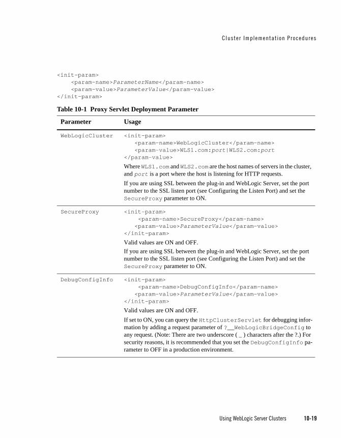
Cluste r Implementat ion P rocedures
Using WebLogic Server Clusters 10-19
<init-param> <param-name>ParameterName</param-name> <param-value>ParameterValue</param-value> </init-param>
Table 10-1 Proxy Servlet Deployment Parameter
Parameter Usage
WebLogicCluster <init-param> <param-name>WebLogicCluster</param-name> <param-value>WLS1.com:port|WLS2.com:port</param-value>
Where WLS1.com and WLS2.com are the host names of servers in the cluster, and port is a port where the host is listening for HTTP requests.If you are using SSL between the plug-in and WebLogic Server, set the port number to the SSL listen port (see Configuring the Listen Port) and set the SecureProxy parameter to ON.
SecureProxy <init-param> <param-name>SecureProxy</param-name> <param-value>ParameterValue</param-value> </init-param>
Valid values are ON and OFF.If you are using SSL between the plug-in and WebLogic Server, set the port number to the SSL listen port (see Configuring the Listen Port) and set the SecureProxy parameter to ON.
DebugConfigInfo <init-param> <param-name>DebugConfigInfo</param-name> <param-value>ParameterValue</param-value> </init-param>
Valid values are ON and OFF. If set to ON, you can query the HttpClusterServlet for debugging infor-mation by adding a request parameter of ?__WebLogicBridgeConfig to any request. (Note: There are two underscore ( _ ) characters after the ?.) For security reasons, it is recommended that you set the DebugConfigInfo pa-rameter to OFF in a production environment.
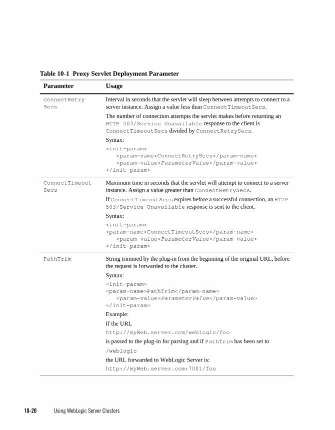
10-20 Using WebLogic Server Clusters
ConnectRetrySecs
Interval in seconds that the servlet will sleep between attempts to connect to a server instance. Assign a value less than ConnectTimeoutSecs. The number of connection attempts the servlet makes before returning an HTTP 503/Service Unavailable response to the client is ConnectTimeoutSecs divided by ConnectRetrySecs. Syntax:<init-param> <param-name>ConnectRetrySecs</param-name> <param-value>ParameterValue</param-value> </init-param>
ConnectTimeoutSecs
Maximum time in seconds that the servlet will attempt to connect to a server instance. Assign a value greater than ConnectRetrySecs. If ConnectTimeoutSecs expires before a successful connection, an HTTP 503/Service Unavailable response is sent to the client.Syntax:<init-param><param-name>ConnectTimeoutSecs</param-name> <param-value>ParameterValue</param-value> </init-param>
PathTrim String trimmed by the plug-in from the beginning of the original URL, before the request is forwarded to the cluster. Syntax:<init-param><param-name>PathTrim</param-name> <param-value>ParameterValue</param-value> </init-param>
Example:If the URLhttp://myWeb.server.com/weblogic/foo
is passed to the plug-in for parsing and if PathTrim has been set to/weblogic the URL forwarded to WebLogic Server is: http://myWeb.server.com:7001/foo
Table 10-1 Proxy Servlet Deployment Parameter
Parameter Usage
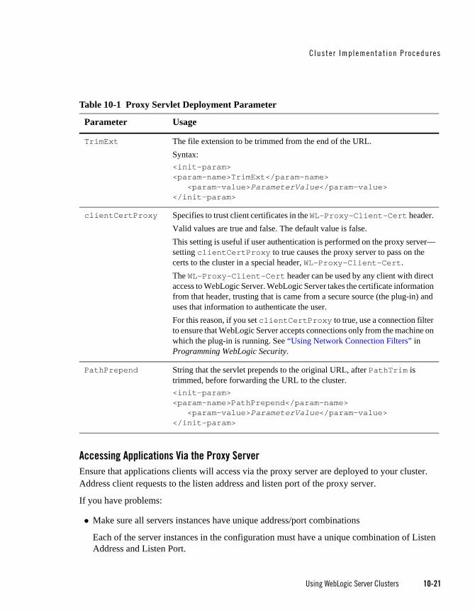
Cluste r Implementat ion P rocedures
Using WebLogic Server Clusters 10-21
Accessing Applications Via the Proxy ServerEnsure that applications clients will access via the proxy server are deployed to your cluster. Address client requests to the listen address and listen port of the proxy server.
If you have problems:
Make sure all servers instances have unique address/port combinations
Each of the server instances in the configuration must have a unique combination of Listen Address and Listen Port.
TrimExt The file extension to be trimmed from the end of the URL.Syntax:<init-param><param-name>TrimExt</param-name> <param-value>ParameterValue</param-value> </init-param>
clientCertProxy Specifies to trust client certificates in the WL-Proxy-Client-Cert header. Valid values are true and false. The default value is false.This setting is useful if user authentication is performed on the proxy server—setting clientCertProxy to true causes the proxy server to pass on the certs to the cluster in a special header, WL-Proxy-Client-Cert. The WL-Proxy-Client-Cert header can be used by any client with direct access to WebLogic Server. WebLogic Server takes the certificate information from that header, trusting that is came from a secure source (the plug-in) and uses that information to authenticate the user.For this reason, if you set clientCertProxy to true, use a connection filter to ensure that WebLogic Server accepts connections only from the machine on which the plug-in is running. See “Using Network Connection Filters” in Programming WebLogic Security.
PathPrepend String that the servlet prepends to the original URL, after PathTrim is trimmed, before forwarding the URL to the cluster.<init-param><param-name>PathPrepend</param-name> <param-value>ParameterValue</param-value> </init-param>
Table 10-1 Proxy Servlet Deployment Parameter
Parameter Usage

10-22 Using WebLogic Server Clusters
Make sure that the proxy servlet is the default application for the proxy server
If you get a page not found error when you try to your application, make sure that weblogic.xml is in \WEB-INF for the application and that it sets the context-root deployment parameter to "/".
When all else fails, restart
If you are having problems try rebooting all your servers, some of the changes you made while configuring your setup may not have been persisted to the configuration file.
Verify Your Configuration
To verify the configuration of the HttpClusterServlet:
a. Set the DebugConfigInfo parameter in web.xml to ON.
b. Use a Web browser to access the following URL:http://myServer:port/placeholder.jsp?__WebLogicBridgeConfig
Where:
myServer is the Managed Server on the proxy machine where HttpClusterServlet runs,
port is the port number on that server that is listening for HTTP requests, and
placeholder.jsp is a file that does not exist on the server.
The plug-in gathers configuration information and run-time statistics and returns the information to the browser. For more information, see “Parameters for Web Server Plug-ins” in Using WebLogic Server with Plug-ins.
Configure Replication GroupsTo support automatic failover for servlets and JSPs, WebLogic Server replicates HTTP session states in memory. You can further control where secondary states are placed using replication groups. A replication group is a preferred list of clustered instances to be used for storing session state replicas.
If your cluster will host servlets or stateful session EJBs, you may want to create replication groups of WebLogic Server instances to host the session state replicas.
For instructions on how to determine which server instances should participate in each replication group, and to determine each server instance’s preferred replication group, follow the instructions in “Using Replication Groups” on page 6-6.

Cluste r Implementat ion P rocedures
Using WebLogic Server Clusters 10-23
Then follow these steps to configure replication groups for each WebLogic Server instance:
To configure replication groups for a WebLogic Server instance:
1. Open the WebLogic Server Console.
2. Select the Environments->Servers node.
3. In the table, click on the name of the server you want to configure.
4. Select the Cluster tab.
5. If you have not already done so, click the Lock & Edit button in the top left corner of the console.
6. Enter values for the following attribute fields:
– Replication Group: Enter the name of the replication group to which this server instance belongs.
– Preferred Secondary Group: Enter the name of the replication group you would like to use to host replicated HTTP session states for this server instance.
7. Click Save to save your changes.
8. Click the Activate Changes button in the top left corner to activate your changes.
Configure Migratable Targets for Pinned ServicesWebLogic Server enables you to configure an optional migratable target, which is a special target that can migrate from one server in a cluster to another. As such, a migratable target provides a way to group pinned services that should move together. When the migratable target is migrated, all services hosted by that target are migrated. Pinned services include JMS-related services (e.g., JMS servers, SAF agents, path services, and persistent stores) or the JTA Transaction Recovery Service.
If you want to use a migratable target, configure the target server list before deploying or activating the service in the cluster. If you do not configure a migratable target in the cluster, migratable services can be migrated to any available WebLogic Server instance in the cluster. For more details on migratable targets, see “Understanding Migratable Targets In a Cluster” on page 8-4.
10-24 Using WebLogic Server Clusters
Configure Clustered JDBCThis section provides instructions for configuring JDBC components using the Administration Console. The choices you make as you configure the JDBC components are reflected in the configuration files for the WebLogic Server domain that contains the cluster.
First you create the data sources and optionally create a multi data source.
For an overview of how JDBC objects work in a WebLogic Server cluster, see “JDBC Connections” on page 2-6.
For a description of how clustered JDBC can increase application availability, see “Failover and JDBC Connections” on page 6-32.
For a description of how clustered JDBC supports load balancing, see “Load Balancing for JDBC Connections” on page 5-16.
Clustering Data SourcesPerform these steps to set up a basic data source in a cluster:
1. Create a data source.
For instructions, see “Create JDBC data sources” in the Administration Console Online Help.
2. Target the data source to the cluster.
Clustering Multi Data SourcesPerform these steps to create a clustered multi data source for increased availability, and optionally, load balancing.
Note: Multi data sources are typically used to provide increased availability and load balancing of connections to replicated, synchronized instances of a database. For more information, see “JDBC Connections” on page 2-6.
1. Create two or more data sources.
For instructions, see “Create JDBC data sources” in the Administration Console Online Help.
2. Target each data source to the cluster.

Cluste r Implementat ion P rocedures
Using WebLogic Server Clusters 10-25
3. Create a multi data source. Assign the data sources created in the previous step to the multi data source.
For instructions, see “Configure JDBC multi data sources” in the Administration Console Online Help.
4. Target the multi data source to the cluster.
Package Applications for DeploymentYou must package applications before you deploy them to WebLogic Server. For more information, see the packaging topic in “Deploying the Application” in Developing Applications for WebLogic Server.
Deploy Applications Clustered objects in WebLogic Server should be deployed homogeneously. To ensure homogeneous deployment, when you select a target use the cluster name, rather than individual WebLogic Server instances in the cluster.
The console automates deploying replica-aware objects to clusters. When you deploy an application or object to a cluster, the console automatically deploys it to all members of the cluster (whether they are local to the Administration Server machine or they reside on remote machines.) For a discussion of application deployment in clustered environments see “Methods of Configuring Clusters” on page 4-8. For a broad discussion of deployment topics, see Deploying WebLogic Server Applications.
Note: All server instances in your cluster should be running when you deploy applications to the cluster using the Administration Console
Deploying to a Single Server Instance (Pinned Deployment)Deploying a application to a server instance, rather than the all cluster members is called a pinned deployment. Although a pinned deployment targets a specific server instance, all server instances in the cluster must be running during the deployment process.
You can perform a pinned deployment using the Administration Console or from the command line, using weblogic.Deployer.
Pinned Deployment from the Command LineFrom a command shell, use the following syntax to target a server instance:

10-26 Using WebLogic Server Clusters
java weblogic.Deployer -activate -name ArchivedEarJar -source
C:/MyApps/JarEar.ear -target server1
Cancelling Cluster DeploymentsYou can cancel a deployment using the Administration Console or from the command line, using weblogic.Deployer.
Cancel Deployment from the Command LineFrom a command shell, use the following syntax to cancel the deployment task ID:
java weblogic.Deployer -adminurl http://admin:7001 -cancel -id tag
Cancel Deployment Using the Administration ConsoleIn the Administration Console, open the Tasks node to view and to cancel any current deployment tasks.
Viewing Deployed ApplicationsTo view a deployed application in the Administration Console:
1. In the Console, click the Deployments node.
2. View a list of deployed applications in the table displayed in the Console.
Undeploying Deployed ApplicationsTo undeploy a deployed application from the WebLogic Server Administration Console:
1. In the Console, click Deployments.
2. In the displayed table, check the checkbox to the left of the application you want to undeploy.
3. If you have not already done so, click the Lock & Edit button in the top left corner of the console.
4. Click Stop.
5. Select when you want the application to stop (undeploy).
6. Click Yes.
7. Click the Activate Changes button in the top left corner of the console to activate your changes.

Cluste r Implementat ion P rocedures
Using WebLogic Server Clusters 10-27
Deploying, Activating, and Migrating Migratable ServicesThe sections that follow provide guidelines and instructions for deploying, activating, and migrating migratable services.
Deploying JMS to a Migratable Target Server InstanceThe migratable target that you create defines the scope of server instances in the cluster that can potentially host a migratable service. You must deploy or activate a pinned service on one of the server instances listed in the migratable target in order to migrate the service within the target server list at a later time. Use the instructions that follow to deploy a JMS service on a migratable target, or activate the JTA transaction recovery system so that you can migrate it later.
Note: If you did not configure a migratable target, simply deploy the JMS server to any WebLogic Server instance in the cluster; you can then migrate the JMS server to any other server instance in the cluster (no migratable target is used).
Before you begin, use the instructions in “Configure Migratable Targets for Pinned Services” on page 10-23 to create a migratable target for the cluster. Next, deploy JMS-related services to a migratable target, as described in the following topics in the Administration Console Online Help:
Change JMS server targets
Change SAF agent targets
Change path service targets
Create file stores and Create JDBC stores
Activating JTA as a Migratable ServiceThe JTA recovery service is automatically started on one of the server instances listed in the migratable target for the cluster; you do not have to deploy the service to a selected server instance.
If you did not configure a JTA migratable target, WebLogic Server activates the service on any available WebLogic Server instance in the cluster. To change the current server instance that hosts the JTA service, use the instructions in “Migrating a Pinned Service to a Target Server Instance” on page 10-27.
Migrating a Pinned Service to a Target Server InstanceAfter you have deployed a migratable service, you can use the Administration Console to manually migrate the service to another server instance in the cluster. If you configured a

10-28 Using WebLogic Server Clusters
migratable target for the service, you can migrate to any other server instance listed in the migratable target, even if that server instance is not currently running. If you did not configure a migratable target, you can migrate the service to any other server instance in the cluster.
If you migrate a service to a stopped server instance, the server instance will activate the service upon the next startup. If you migrate a service to a running WebLogic Server instance, the migration takes place immediately.
Before you begin, use the instructions in “Deploying JMS to a Migratable Target Server Instance” on page 10-27 to deploy a pinned service to the cluster. Next, migrate the pinned service using the Administration Console by following the appropriate instructions in the Administration Console Online Help:
Manually migrate JMS-related services
Manually migrate the Transaction Recovery Service
Here are some additional steps that are not covered in the console help instructions:
1. If the Current Server is not reachable by the Administration Server, the Administration Console displays this message:Unable to contact server MyServer-1, the source server from which services are being migrated.
Please ensure that server MyServer-1 is NOT running! If the administration server cannot reach server MyServer-1 due to a network partition, inspect the server directly to verify that it is not running. Continue the migration only if MyServer-1 is not running. Cancel the migration if MyServer-1 is running, or if you do not know whether it is running.
If this message is displayed, perform the procedure described in “Migrating When the Currently Active Host is Unavailable” on page 10-29.
2. If the Destination Server is stopped, the Administration Console notifies you of the stopped server instance and asks if you would like to continue the migration. Click the Continue button to migrate to the stopped server instance, or click Cancel to stop the migration and select a different server instance.
3. The migration process may take several minutes to complete, depending on the server instance configuration. However, you can continue using other Administration Console features while the migration takes place. To view the migration status at a later time, click the Tasks node in the left pane to display the currently-running tasks for the domain; then select the task description for the migration task to view the current status.

Cluste r Implementat ion P rocedures
Using WebLogic Server Clusters 10-29
Migrating When the Currently Active Host is UnavailableUse this migration procedure if a clustered Managed Server that was the active server for the migratable service crashes or becomes unreachable.
This procedure purges the failed Managed Server’s configuration cache. The purpose of purging the cache is to ensure that, when the failed server instance is once again available, it does not re-deploy a service that you have since migrated to another Managed Server. Purging the cache eliminates the risk that Managed Server which was previously the active host for the service uses local, out-of-date configuration data when it starts up again.
1. Disconnect the machine from the network entirely. It should not be accessible to the Administration Server or client traffic. If the machine has a dual ported disk, disconnect it.
2. Migrate the migratable service(s) to a Managed Server instance on a different machine. The Administration Server must be running, so that it can coordinate the migration and update the activation table.
– If you use the command line for migration, use the -sourcedown flag.
– If you use the console, it will ask you to make sure the source server is not going to restart.
The migratable service is now available on a different Managed Server on a different machine. The following steps can be performed at leisure.
3. Perform the necessary repair or maintenance on the failed machine.
4. Reboot the machine, but do not connect it to the network.
Node Manager will start as a service or daemon, and will attempt to start the Managed Servers on the machine.
– If Managed Server Independence is enabled, the Managed Server will start, even though it cannot connect to the Administration Server.
– If Managed Server Independence is disabled, the Managed Server will not start, because it cannot connect to the Administration Server.
5. Reconnect the machine to the network and shared storage, including dual ported disk, if applicable.
6. Restart the Node Manager daemon/service or reboot the machine, to start all remaining Managed Servers.
7. Start the Managed Server that was disabled. This is a normal start up, rather than a restart performed by Node Manager. The Administration Server must be reachable and running, so

10-30 Using WebLogic Server Clusters
that the Managed Servers can synchronize with the migratable service activation table on the Administration Server—and hence know that it is no longer the active host of the migratable service.
Configure In-Memory HTTP ReplicationTo support automatic failover for servlets and JSPs, WebLogic Server replicates HTTP session states in memory.
Note: WebLogic Server can also maintain the HTTP session state of a servlet or JSP using file-based or JDBC-based persistence. For more information on these persistence mechanisms, see “Using Sessions and Session Persistence” in Developing Web Applications, Servets, and JSPs for WebLogic Server.
In-memory HTTP Session state replication is controlled separately for each application you deploy. The parameter that controls it—PersistentStoreType—appears within the session-descriptor element, in the WebLogic deployment descriptor file, weblogic.xml, for the application.
domain_directory/applications/application_directory/Web-Inf/weblogic.xml
To use in-memory HTTP session state replication across server instances in a cluster, set the PersistentStoreType to replicated. The fragment below shows the appropriate XML from weblogic.xml.
<session-descriptor>
<session-param>
<param-name> PersistentStoreType </param-name>
<param-value> replicated </param-value>
</session-param>
</session-descriptor>
Additional Configuration TopicsThe sections below contain useful tips for particular cluster configurations.
Configure IP SocketsFor best socket performance, BEA recommends that you use the native socket reader implementation, rather than the pure-Java implementation, on machines that host WebLogic Server instances.

Cluste r Implementat ion P rocedures
Using WebLogic Server Clusters 10-31
If you must use the pure-Java socket reader implementation for host machines, you can still improve the performance of socket communication by configuring the proper number of socket reader threads for each server instance and client machine.
To learn more about how IP sockets are used in a cluster, and why native socket reader threads provide best performance, see “Peer-to-Peer Communication Using IP Sockets” on page 3-5, and “Client Communication via Sockets” on page 3-10.
For instructions on how to determine how many socket reader threads are necessary in your cluster, see “Determining Potential Socket Usage” on page 3-8. If you are deploying a servlet cluster in a multi-tier cluster architecture, this has an effect on how many sockets you require, as described in “Configuration Considerations for Multi-Tier Architecture” on page 9-10.
The sections that follow have instructions on how to configure native socket reader threads for host machines, and how to set the number of reader threads for host and client machines.
Configure Native IP Sockets Readers on Machines that Host Server InstancesTo configure a WebLogic Server instance to use the native socket reader threads implementation:
1. Open the WebLogic Server Administration Console.
2. Select the Environments->Servers node.
3. Click the name of the server instance you want to configure.
4. If you have not already done so, click the Lock & Edit button in the top left corner of the console.
5. Select the Configuration->Tuning tab.
6. Check the Enable Native IO box.
7. Click Save.
8. Click the Activate Changes button in the top left corner of the console to activate your changes.
Set the Number of Reader Threads on Machines that Host Server InstancesBy default, a WebLogic Server instance creates three socket reader threads upon booting. If you determine that your cluster system may utilize more than three sockets during peak periods, increase the number of socket reader threads:

10-32 Using WebLogic Server Clusters
1. Open the WebLogic Server Administration Console.
2. Select the Environments->Servers node.
3. Click the name of the server instance you want to configure.
4. If you have not already done so, click the Lock & Edit button in the top left corner of the console.
5. Select the Configuration->Tuning tab.
6. Edit the percentage of Java reader threads in the Socket Readers field. The number of Java socket readers is computed as a percentage of the number of total execute threads (as shown in the Execute Threads field).
7. Click Save to save your changes.
8. Click the Activate Changes button in the top left corner of the console to activate your changes.
Set the Number of Reader Threads on Client Machines On client machines, you can configure the number socket reader threads in the Java Virtual Machine (JVM) that runs the client. Specify the socket readers by defining the -Dweblogic.ThreadPoolSize=value and -Dweblogic.ThreadPoolPercentSocketReaders=value options in the Java command line for the client.
Configure Multicast Time-To-Live (TTL)If your cluster spans multiple subnets in a WAN, the value of the Multicast Time-To-Live (TTL) parameter for the cluster must be high enough to ensure that routers do not discard multicast packets before they reach their final destination. The Multicast TTL parameter sets the number of network hops a multicast message makes before the packet can be discarded. Configuring the Multicast TTL parameter appropriately reduces the risk of losing the multicast messages that are transmitted among server instances in the cluster.
For more information about planning your network topology to ensure that multicast messages are reliably transmitted see “If Your Cluster Spans Multiple Subnets In a WAN” on page 3-3.
To configure the Multicast TTL for a cluster, change the Multicast TTL value in the Multicast tab for the cluster in the Administration Console. The config.xml excerpt below shows a cluster with a Multicast TTL value of three. This value ensures that the cluster’s multicast messages can pass through three routers before being discarded:

Cluste r Implementat ion P rocedures
Using WebLogic Server Clusters 10-33
<Cluster
Name="testcluster"
ClusterAddress="wanclust"
MulticastAddress="wanclust-multi"
MulticastTTL="3"
/>
Note: When relying upon the Multicast TTL value, it is important to remember that within a clustered environment it is possible that timestamps across servers may not always be synchronized. This can occur in replicated HTTP sessions and EJBs for example.
When the ClusterDebug flag is enabled, an error is printed to the server log when cluster members clocks are not synchronized.
Configure Multicast Buffer SizeIf multicast storms occur because server instances in a cluster are not processing incoming messages on a timely basis, you can increase the size of multicast buffers. For information on multicast storms, see “If Multicast Storms Occur” on page 3-4.
TCP/IP kernel parameters can be configured with the UNIX ndd utility. The udp_max_buf parameter controls the size of send and receive buffers (in bytes) for a UDP socket. The appropriate value for udp_max_buf varies from deployment to deployment. If you are experiencing multicast storms, increase the value of udp_max_buf by 32K, and evaluate the effect of this change.
Do not change udp_max_buf unless necessary. Before changing udp_max_buf, read the Sun warning in the “UDP Parameters with Additional Cautions” section in the “TCP/IP Tunable Parameters” chapter in Solaris Tunable Parameters Reference Manual at http://docs.sun.com/?p=/doc/806-6779/6jfmsfr7o&.
Configure Multicast Data EncryptionWebLogic server allows you to encrypt multicast messages that are sent between clusters. You can enable this option by checking Enable Multicast Data Encryption from the Administration Console by navigating to the Environment —>Clusters—><cluster_name>—>Multicast node and selecting the Advanced options.
Only the data portion of the multicast message is encrypted. Information contained in the multicast header is not encrypted.
10-34 Using WebLogic Server Clusters
Configure Machine NamesConfigure a Machine Name if:
Your cluster will span multiple machines, and multiple server instances will run on individual machines in the cluster, or
You plan to run Node Manager on a machine that does not host a Administration Server
WebLogic Server uses configured machine names to determine whether or not two server instances reside on the same physical hardware. Machine names are generally used with machines that host multiple server instances. If you do not define machine names for such installations, each instance is treated as if it resides on separate physical hardware. This can negatively affect the selection of server instances to host secondary HTTP session state replicas, as described in “Using Replication Groups” on page 6-6.
Configuration Notes for Multi-Tier ArchitectureIf your cluster has a multi-tier architecture, see the configuration guidelines in “Configuration Considerations for Multi-Tier Architecture” on page 9-10.
Enable URL Rewriting In its default configuration, WebLogic Server uses client-side cookies to keep track of the primary and secondary server instance that host the client’s servlet session state. If client browsers have disabled cookie usage, WebLogic Server can also keep track of primary and secondary server instances using URL rewriting. With URL rewriting, both locations of the client session state are embedded into the URLs passed between the client and proxy server. To support this feature, you must ensure that URL rewriting is enabled on the WebLogic Server cluster. For instructions on how to enable URL rewriting, see “Using URL Rewriting” in Developing Web Applications for WebLogic Server.

Using WebLogic Server Clusters 11-1
C H A P T E R 11
Clustering Best Practices
These topics recommend design and deployment practices that maximize the scalability, reliability, and performance of applications hosted by a WebLogic Server Cluster.
“General Design Considerations” on page 11-1
“Web Application Design Considerations” on page 11-2
“EJB Design Considerations” on page 11-3
“State Management in a Cluster” on page 11-7
“Application Deployment Considerations” on page 11-13
“Architecture Considerations” on page 11-13
“Avoiding Problems” on page 11-13
General Design ConsiderationsThe following sections describe general design guidelines for clustered applications.
Strive for SimplicityDistributed systems are complicated by nature. For a variety of reasons, make simplicity a primary design goal. Minimize “moving parts” and do not distribute algorithms across multiple objects.

11-2 Using WebLogic Server Clusters
Minimize Remote CallsYou improve performance and reduce the effects of failures by minimizing remote calls.
Session Facades Reduce Remote CallsAvoid accessing EJB entity beans from client or servlet code. Instead, use a session bean, referred to as a facade, to contain complex interactions and reduce calls from web applications to RMI objects. When a client application accesses an entity bean directly, each getter method is a remote call. A session facade bean can access the entity bean locally, collect the data in a structure, and return it by value.
Transfer Objects Reduce Remote CallsEJBs consume significant system resources and network bandwidth to execute—they are unlikely to be the appropriate implementation for every object in an application.
Use EJBs to model logical groupings of an information and associated business logic. For example, use an EJB to model a logical subset of the line items on an invoice—for instance, items to which discounts, rebates, taxes, or other adjustments apply.
In contrast, an individual line item in an invoice is fine-grained—implementing it as an EJB wastes network resources. Implement objects that simply represents a set of data fields, which require only get and set functionality, as transfer objects.
Transfer objects (sometimes referred to as value objects or helper classes) are good for modeling entities that contain a group of attributes that are always accessed together. A transfer object is a serializable class within an EJB that groups related attributes, forming a composite value. This class is used as the return type of a remote business method.
Clients receive instances of this class by calling coarse-grained business methods, and then locally access the fine-grained values within the transfer object. Fetching multiple values in one server round-trip decreases network traffic and minimizes latency and server resource usage.
Distributed Transactions Increase Remote CallsAvoid transactions that span multiple server instances. Distributed transactions issue remote calls and consume network bandwidth and overhead for resource coordination.
Web Application Design ConsiderationsThe following sections describe design considerations for clustered servlets and JSPs.

EJB Des ign Cons iderat ions
Using WebLogic Server Clusters 11-3
Configure In-Memory Replication To enable automatic failover of servlets and JSPs, session state must persist in memory. For instructions to configure in-memory replication for HTTP session states, see “Requirements for HTTP Session State Replication” on page 6-4 and “Configure In-Memory HTTP Replication” on page 10-30.
Design for Idempotence Failures or impatient users can result in duplicate servlet requests. Design servlets to tolerate duplicate requests.
Programming ConsiderationsSee “Programming Considerations for Clustered Servlets and JSPs” on page 6-5.
EJB Design ConsiderationsThe following sections describe design considerations for clustered RMI objects.
Design Idempotent MethodsIt is not always possible to determine when a server instance failed with respect to the work it was doing at the time of failure. For instance, if a server instance fails after handling a client request but before returning the response, there is no way to tell that the request was handled. A user that does not get a response retries, resulting in an additional request.
Failover for RMI objects requires that methods be idempotent. An idempotent method is one that can be repeated with no negative side-effects.

11-4 Using WebLogic Server Clusters
Follow Usage and Configuration GuidelinesThe following table summarizes usage and configuration guidelines for EJBs. For a list of configurable cluster behaviors, see Table 11-2.
Table 11-1 EJB Types and Guidelines
Object Type Usage Configuration
EJBs of all types
Use EJBs to model logical groupings of an information and associated business logic. See “Transfer Objects Reduce Remote Calls” on page 11-2.
Configure clusterable homes
Stateful session beans
Recommended for high volume, heavy-write transactions.
Remove stateful session beans when finished to minimize EJB container overhead. A stateful session bean instance is associated with a particular client, and remains in the container until explicitly removed by the client, or removed by the container when it times out. Meanwhile, the container may passivate inactive instances to disk. This consumes overhead and can affect performance.
Note: Although unlikely, the current state of a stateful session bean can be lost. For example, if a client commits a transaction involving the bean and there is a failure of the primary server before the state change is replicated, the client will fail over to the previously-stored state of the bean. If it is critical to preserve bean state in all possible failover scenarios, use an entity EJB rather than a stateful session EJB.
Configure clusterable homes
Configure in-memory replication for EJBs

EJB Des ign Cons iderat ions
Using WebLogic Server Clusters 11-5
Stateless Session Beans
Scale better than stateful session beans which are instantiated on a per client basis, and can multiply and consume resources rapidly.
When a home creates a stateless bean, it returns a replica-aware stub that can route to any server where the bean is deployed. Because a stateless bean holds no state on behalf of the client, the stub is free to route any call to any server that hosts the bean.
Configure clusterable homes.
Configure Cluster Address.
Configure methods to be idempotence to support failover during method calls. (Failover is default behavior if failure occurs between method calls.or if the method fails to connect to a server).
The methods on stateless session bean homes are automatically set to be idempotent. It is not necessary to explicitly specify them as idempotent.
Read-only Entity Beans
Recommended whenever stale data is tolerable—suitable for product catalogs and the majority of content within many applications. Reads are performed against a local cache that is invalided on a timer basis. Read-only entities perform three to four times faster than transactional entities.
Note: A client can successfully call setter methods on a read-only entity bean, however the data will never be moved into the persistent store.
Configure clusterable homes.
Configure Cluster Address.
Methods are configured to be idempotent by default.
Read-Write Entity Beans
Best suited for shared persistent data that is not subject to heavy request and update.If the access/update load is high, consider session beans and JDBC.
Recommended for applications that require high data consistency, for instance, customer account maintenance. All reads and writes are performed against the database.
Use the isModified method to reduce writes.
For read-mostly applications, characterized by frequent reads, and occasional updates (for instance, a catalog)—a combination of read-only and read-write beans that extend the read-only beans is suitable. The read-only bean provides fast, weakly consistent reads, while the read-write bean provides strongly consistent writes.
Configure clusterable homes
Configure methods to be idempotence to support failover during method calls. (Failover is default behavior if failure occurs between method calls.or if the method fails to connect to a server).
The methods on read-only entity beans are automatically set to be idempotent.
Table 11-1 EJB Types and Guidelines
Object Type Usage Configuration
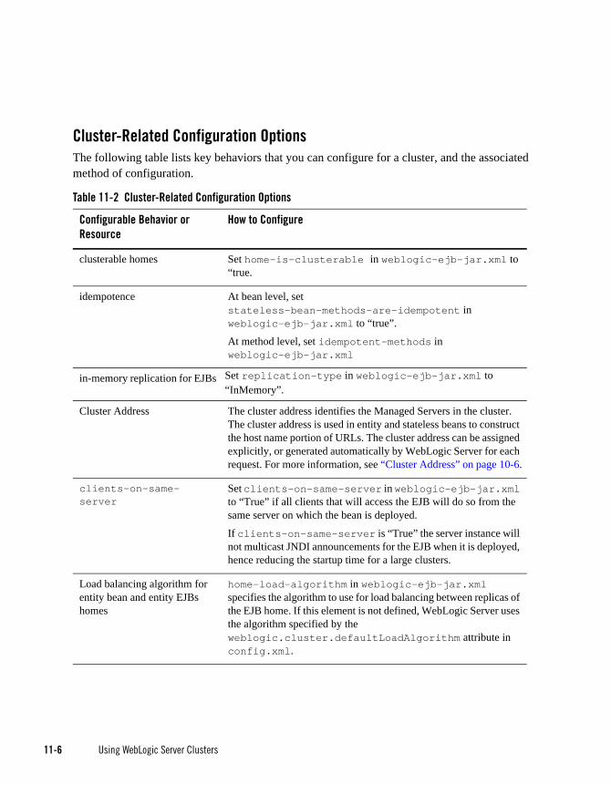
11-6 Using WebLogic Server Clusters
Cluster-Related Configuration OptionsThe following table lists key behaviors that you can configure for a cluster, and the associated method of configuration.
Table 11-2 Cluster-Related Configuration Options
Configurable Behavior or Resource
How to Configure
clusterable homes Set home-is-clusterable in weblogic-ejb-jar.xml to “true.
idempotence At bean level, set stateless-bean-methods-are-idempotent in weblogic-ejb-jar.xml to “true”.
At method level, set idempotent-methods in weblogic-ejb-jar.xml
in-memory replication for EJBs Set replication-type in weblogic-ejb-jar.xml to “InMemory”.
Cluster Address The cluster address identifies the Managed Servers in the cluster. The cluster address is used in entity and stateless beans to construct the host name portion of URLs. The cluster address can be assigned explicitly, or generated automatically by WebLogic Server for each request. For more information, see “Cluster Address” on page 10-6.
clients-on-same-server
Set clients-on-same-server in weblogic-ejb-jar.xml to “True” if all clients that will access the EJB will do so from the same server on which the bean is deployed.
If clients-on-same-server is “True” the server instance will not multicast JNDI announcements for the EJB when it is deployed, hence reducing the startup time for a large clusters.
Load balancing algorithm for entity bean and entity EJBs homes
home-load-algorithm in weblogic-ejb-jar.xml specifies the algorithm to use for load balancing between replicas of the EJB home. If this element is not defined, WebLogic Server uses the algorithm specified by the weblogic.cluster.defaultLoadAlgorithm attribute in config.xml.

State Management in a C lus te r
Using WebLogic Server Clusters 11-7
State Management in a ClusterDifferent services in a WebLogic Server cluster provide varying types and degrees of state management. This list defines four categories of service that are distinguished by how they maintain state in memory or persistent storage:
Custom load balancing for entity EJBs, stateful session EJBs, and stateless session
Use home-call-router-class-name in weblogic-ejb-jar.xml to specify the name of a custom class to use for routing bean method calls for these types of beans. This class must implement weblogic.rmi.cluster.CallRouter(). For more information, see “The WebLogic Cluster API” on page A-1.
Custom load balancing for stateless session bean
Use stateless-bean-call-router-class-name in weblogic-ejb-jar.xml to specify the name of a custom class to use for routing stateless session bean method calls. This class must implement weblogic.rmi.cluster.CallRouter(). For more information, see “The WebLogic Cluster API” on page A-1.
Configure stateless session bean as clusterable
Set stateless-bean-is-clusterable in weblogic-ejb-jar.xml to “true” to allow the EJB to be deployed to a cluster.
Load balancing algorithm for stateless session beans.
Use stateless-bean-load-algorithm in weblogic-ejb-jar.xml to specify the algorithm to use for load balancing between replicas of the EJB home. If this property is not defined, WebLogic Server uses the algorithm specified by the weblogic.cluster.defaultLoadAlgorithm attribute in config.xml.
Machine The WebLogic Server Machine resource associates server instances with the computer on which it runs. For more information, see “Configure Machine Names” on page 10-34.
Replication groups Replication groups allow you to control where HTTP session states are replicated. For more information, see “Configure Replication Groups” on page 10-22
Table 11-2 Cluster-Related Configuration Options
Configurable Behavior or Resource
How to Configure

11-8 Using WebLogic Server Clusters
Stateless services—A stateless service does not maintain state in memory between invocations.
Conversational services—A conversational service is dedicated to a particular client for the duration of a session. During the session, it serves all requests from the client, and only requests from that client. Throughout a session there is generally state information that the the application server must maintain between requests. Conversational services typically maintain transient state in memory, which can be lost in the event of failure. If session state is written to a shared persistent store between invocations, the service is stateless. If persistent storage of state is not required, alternatives for improving performance and scalability include:
– Session state can be sent back and forth between the client and server under the covers, again resulting in a stateless service. This approach is not always feasible or desirable, particularly with large amounts of data.
– More commonly, session state may be retained in memory on the application server between requests. Session state can be paged out from memory as necessary to free up memory. Performance and scalability are still improved in this case because updates are not individually written to disk and the data is not expected to survive server failures.
Cached services—A cached service maintains state in memory and uses it to process requests from multiple clients. Implementations of cached services vary in the extent to which they keep the copies of cached data consistent with each other and with associated data in the backing store.
Singleton services—A singleton service is active on exactly one server in the cluster at a time and processes requests from multiple clients. A singleton service is generally backed by private, persistent data, which it caches in memory. It may also maintain transient state in memory, which is either regenerated or lost in the event of failure. Upon failure, a singleton service must be restarted on the same server or migrated to a new server.
Table 11-3 summarizes how Java EE and WebLogic support different each of these categories of service.
Note: In Table 11-3, support for stateless and conversational services is described for two types of clients:
Loosely-coupled clients include browsers or Web Service clients that communicate with the application server using standard protocols.
Tightly-coupled clients are objects that run in the application tier or in the client-side environment, and communicate with the application server using proprietary protocols.

State Management in a C lus te r
Using WebLogic Server Clusters 11-9
Table 11-3 Java EE and WebLogic Support for Service Types
Service Java EE Support WebLogic Server Scalability and Reliability Features for...
Stateless Service with loosely-coupled clients
All Java EE APIs are either stateless or may be implemented in a stateless manner by writing state information to a shared persistent store between invocations.
Java EE does not specify a standard for load balancing and failover. For loosely coupled clients, load balancing must be must be performed by external IP-based mechanisms
WebLogic Server increases the availability of stateless services by deploying multiple instances of the service to a cluster.
For loosely-coupled clients of a stateless service, WebLogic Server supports external load balancing solutions, and provides proxy plug-ins for session failover and load balancing.
For more information, see: • “Stateless Session Beans” on page 6-27• “Load Balancing HTTP Sessions with an External
Load Balancer” on page 5-2• “Load Balancing with a Proxy Plug-in” on page 5-2
Stateless Service with tightly-coupled clients
These Java EE APIs support tightly coupled access to stateless services:• JNDI (after initial
access)• Factories, such as EJB
homes, JDBC connection pools, and JMS connection factories
• Stateless session beans• Entity beans, if written
to a shared persistent store between invocations
WebLogic Server increases the availability of stateless services by deploying multiple instances of the service to a cluster.
For tightly-coupled clients of a stateless service, WebLogic Server supports load balancing and failover in its RMI implementation.
The WebLogic Server replica-aware stub for a clustered RMI object lists the server instances in the cluster that currently offer the service, and the configured load balancing algorithm for the object. WebLogic Server uses the stub to make load balancing and failover decisions.
For more information, see: • “Stateless Session Beans” on page 6-27• “Load Balancing for EJBs and RMI Objects” on
page 5-4

11-10 Using WebLogic Server Clusters
Conversational services with loosely-coupled clients
These Java EE APIs support loosely-coupled access to conversational services:• Servlets• Web Services
Java EE does not specify a standard for load balancing and failover.
Load balancing can be accomplished with external IP-based mechanisms or application server code in the presentation tier. Because protocols for conversations services are stateless, load balancing should occur only when the session is created. Subsequent requests should stick to the selected server.
WebLogic Server increases the reliability of sessions with:• Failover, based on in-memory replication of session
state, and distribution of primaries and secondaries across the cluster.
• Configurable replication groups, and the ability to specify preferred replication groups for hosting secondaries.
• Load balancing using external load balancers or proxy-plug-ins.
For more information, see • “HTTP Session State Replication” on page 6-3• “Load Balancing for Servlets and JSPs” on page 5-1.
Table 11-3 Java EE and WebLogic Support for Service Types
Service Java EE Support WebLogic Server Scalability and Reliability Features for...

State Management in a C lus te r
Using WebLogic Server Clusters 11-11
Conversational services with tightly-coupled clients
The Java EE standard provides EJB stateful session beans to support conversational services with tightly-coupled clients.
WebLogic Server increases the availability and reliability of stateful session beans with these features:• Caching• Persistent storage of passivated bean state.• Initial load balancing occurs when an EJB home is
chosen to create the bean. The replica-aware stub is hard-wired to the chosen server, providing session affinity.
• When primary/secondary replication is enabled, the stub keeps track of the secondary and performs failover.
• Updates are sent from the primary to the secondary only on transaction boundaries.
For more information, see “Stateful Session Beans” on page 6-28.
Table 11-3 Java EE and WebLogic Support for Service Types
Service Java EE Support WebLogic Server Scalability and Reliability Features for...
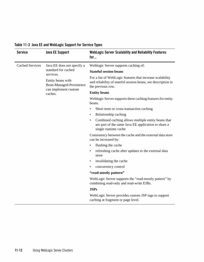
11-12 Using WebLogic Server Clusters
Cached Services Java EE does not specify a standard for cached services.
Entity beans with Bean-Managed-Persistence can implement custom caches.
Weblogic Server supports caching of:
Stateful session beans
For a list of WebLogic features that increase scalability and reliability of stateful session beans, see description in the previous row.
Entity beans
Weblogic Server supports these caching features for entity beans.• Short term or cross-transaction caching • Relationship caching• Combined caching allows multiple entity beans that
are part of the same Java EE application to share a single runtime cache
Consistency between the cache and the external data store can be increased by: • flushing the cache• refreshing cache after updates to the external data
store • invalidating the cache• concurrency control
“read-mostly pattern”
WebLogic Server supports the “read-mostly pattern” by combining read-only and read-write EJBs.
JSPs
WebLogic Server provides custom JSP tags to support caching at fragment or page level.
Table 11-3 Java EE and WebLogic Support for Service Types
Service Java EE Support WebLogic Server Scalability and Reliability Features for...

Appl i cat ion Dep lo yment Cons iderat ions
Using WebLogic Server Clusters 11-13
Application Deployment ConsiderationsDeploy clusterable objects to the cluster, rather than to individual Managed Servers in the cluster. For information and recommendations, see Deploying Applications to WebLogic Server.
Architecture ConsiderationsFor information about alternative cluster architectures, load balancing options, and security options, see “Cluster Architectures” on page 9-1.
Avoiding ProblemsThe following sections present considerations to keep in mind when planning and configuring a cluster.
Singleton Services
Java EE APIs used to implement singleton services include:• JMS Destinations,• JTA transaction
managers• Cached entity beans
with pessimistic concurrency control
Scalability can be increased by “partitioning” the service into multiple instances, each of which handles a different slice of the backing data and its associated requests
WLS features for increasing the availability of singleton services include: • Support for multiple thread pools for servers, to
harden individual servers against failures• Health monitoring and lifecycle APIs to support
detection restart of failed and ailing servers• Ability to upgrade software without interrupting
services• Ability to migrate JMS servers and JTA transaction
recovery services.
Table 11-3 Java EE and WebLogic Support for Service Types
Service Java EE Support WebLogic Server Scalability and Reliability Features for...

11-14 Using WebLogic Server Clusters
Naming ConsiderationsFor guidelines for how to name and address server instances in cluster, see “Identify Names and Addresses” on page 10-3.
Administration Server ConsiderationsTo start up WebLogic Server instances that participate in a cluster, each Managed Server must be able to connect to the Administration Server that manages configuration information for the domain that contains the cluster. For security purposes, the Administration Server should reside within the same DMZ as the WebLogic Server cluster.
The Administration Server maintains the configuration information for all server instances that participate in the cluster. The config.xml file that resides on the Administration Server contains configuration data for all clustered and non-clustered servers in the Administration Server’s domain. You do not create a separate configuration file for each server in the cluster.
The Administration Server must be available in order for clustered WebLogic Server instances to start up. Note, however, that once a cluster is running, a failure of the Administration Server does not affect ongoing cluster operation.
The Administration Server should not participate in a cluster. The Administration Server should be dedicated to the process of administering servers: maintaining configuration data, starting and shutting down servers, and deploying and undeploying applications. If the Administration Server also handles client requests, there is a risk of delays in accomplishing administration tasks.
There is no benefit in clustering an Administration Server; the administrative objects are not clusterable, and will not failover to another cluster member if the administrative server fails. Deploying applications on an Administration Server can reduce the stability of the server and the administrative functions it provides. If an application you deploy on the Administration Server behaves unexpectedly, it could interrupt operation of the Administration Server.
For these reasons, make sure that the Administration Server’s IP address is not included in the cluster-wide DNS name.
Firewall Considerations If your configuration includes a firewall, locate your proxy server or load-balancer in your DMZ, and the cluster, both Web and EJB containers, behind the firewall. Web containers in DMZ are not recommended. See “Basic Firewall for Proxy Architectures” on page 9-17.

Avo id ing P rob lems
Using WebLogic Server Clusters 11-15
If you place a firewall between the servlet cluster and object cluster in a multi-tier architecture, bind all servers in the object cluster to public DNS names, rather than IP addresses. Binding those servers with IP addresses can cause address translation problems and prevent the servlet cluster from accessing individual server instances.
If the internal and external DNS names of a WebLogic Server instance are not identical, use the ExternalDNSName attribute for the server instance to define the server's external DNS name. Outside the firewall the ExternalDNSName should translate to external IP address of the server. Set this attribute in the Administration Console using the Server—>Configuration—>General tab. See Server—>Configuration—>General in Administration Console Online Help.
In any cluster architecture that utilizes one or more firewalls, it is critical to identify all WebLogic Server instances using publicly-available DNS names, rather than IP addresses. Using DNS names avoids problems associated with address translation policies used to mask internal IP addresses from untrusted clients.
Notes: Use of ExternalDNSName is required for configurations in which a firewall is performing Network Address Translation, unless clients are accessing WebLogic Server using t3 and the default channel. For instance, ExternalDNSName is required for configurations in which a firewall is performing Network Address Translation, and clients are accessing WebLogic Server using HTTP via a proxy plug-in.
The following figure describes the potential problem with using IP addresses to identify WebLogic Server instances. In this figure, the firewall translates external IP requests for the subnet “xxx” to internal IP addresses having the subnet “yyy.”

11-16 Using WebLogic Server Clusters
Figure 11-1 Translation Errors Can Occur When Servers are Identified by IP Addresses
The following steps describe the connection process and potential point of failure:
1. The client initiates contact with the WebLogic Server cluster by requesting a connection to the first server at 205.20.xxx.100:7001. The firewall translates this address and connects the client to the internal IP address of 205.20.yyy.100:7001.
2. The client performs a JNDI lookup of a pinned Object C that resides on the third WebLogic Server instance in the cluster. The stub for Object C contains the internal IP address of the server hosting the object, 205.20.yyy.300:7001.
3. When the client attempts to instantiate Object C, it requests a connection to the server hosting the object using IP address 205.20.yyy.300:7001. The firewall denies this connection, because the client has requested a restricted, internal IP address, rather than the publicly-available address of the server.
If there was no translation between external and internal IP addresses, the firewall would pose no problems to the client in the above scenario. However, most security policies involve hiding (and denying access to) internal IP addresses.
JDBC
EJBHTTPJSP
Servlet
JDBC
EJBHTTPJSP
Servlet
JDBC
EJBHTTPJSP
Servlet
Fire
wal
l
WebLogic ServerCluster
205.20.xxx.100:7001 205.20.yyy.100:7001
205.20.yyy.300:7001
205.20.yyy.300:7001
205.20.yyy.300:7001
Clie
nt
Object C at
Request Object C at
C

Avo id ing P rob lems
Using WebLogic Server Clusters 11-17
Evaluate Cluster Capacity Prior to Production UseThe architecture of your cluster will influence the capacity of your system. Before deploying applications for production use, evaluate performance to determine if and where you may need to add servers or server hardware to support real-world client loads. Testing software such as LoadRunner from Mercury Interactive allows you to simulate heavy client usage.

11-18 Using WebLogic Server Clusters

Using WebLogic Server Clusters 12-1
C H A P T E R 12
Troubleshooting Common Problems
This chapter provides guidelines on how to prevent cluster problems or troubleshoot them if they do occur.
Before You Start the ClusterYou can do a number of things to help prevent problems before you boot the cluster.
Check the Server Version NumbersAll servers in the cluster must have the same major version number, but can have different minor version numbers and service packs.
The cluster’s Administration Server is typically not configured as a cluster member, but it should run the same major version of WebLogic Server used on the managed servers.
Check the Multicast AddressA problem with the multicast address is one of the most common reasons a cluster does not start or a server fails to join a cluster.
A multicast address is required for each cluster. The multicast address can be an IP number between 224.0.0.0 and 239.255.255.255, or a host name with an IP address within that range.
You can check a cluster’s multicast address and port on its Configuration-->Multicast tab in the Administration Console.

12-2 Using WebLogic Server Clusters
For each cluster on a network, the combination of multicast address and port must be unique. If two clusters on a network use the same multicast address, they should use different ports. If the clusters use different multicast addresses, they can use the same port or accept the default port, 7001.
Before booting the cluster, make sure the cluster’s multicast address and port are correct and do not conflict with the multicast address and port of any other clusters on the network.
The errors you are most likely to see if the multicast address is bad are:Unable to create a multicast socket for clustering
Multicast socket send error
Multicast socket receive error
Check the CLASSPATH ValueMake sure the value of CLASSPATH is the same on all managed servers in the cluster. CLASSPATH is set by the setEnv script, which you run before you run startManagedWebLogic to start the managed servers.
By default, setEnv sets this value for CLASSPATH (as represented on Windows systems):
set WL_HOME=C:\bea\wlserver_10.00
set JAVA_HOME=C:\bea\jdk131
.
.
set CLASSPATH=%JAVA_HOME%\lib\tools.jar;
%WL_HOME%\server\lib\weblogic_sp.jar;
%WL_HOME%\server\lib\weblogic.jar;
%CLASSPATH%
If you change the value of CLASSPATH on one managed server, or change how setEnv sets CLASSPATH, you must change it on all managed servers in the cluster.
Check the Thread CountEach server instance in the cluster has a default execute queue, configured with a fixed number of execute threads. To view the thread count for the default execute queue, choose the Configure Execute Queue command on the Advanced Options portion of the Configuration> General tab for the server. The default thread count for the default queue is 15, and the minimum value is 5. If the value of Thread Count is below 5, change it to a higher value so that the Managed Server does not hang on startup.

Afte r You Star t the C lus te r
Using WebLogic Server Clusters 12-3
After You Start the Cluster
Check Your CommandsIf the cluster fails to start, or a server fails to join the cluster, the first step is to check any commands you have entered, such as startManagedWebLogic or a java interpreter command, for errors and misspellings.
Generate a Log FileBefore contacting BEA Technical Support for help with cluster-related problems, collect diagnostic information. The most important information is a log file with multiple thread dumps from a Managed Server. The log file is especially important for diagnosing cluster freezes and deadlocks.
Remember: a log file that contains multiple thread dumps is a prerequisite for diagnosing your problem.
1. Stop the server.
2. Remove or back up any log files you currently have. You should create a new log file each time you boot a server, rather than appending to an existing log file.
3. Start the server with this command, which turns on verbose garbage collection and redirects both the standard error and standard output to a log file:
% java -ms64m -mx64m -verbose:gc -classpath $CLASSPATH-Dweblogic.domain=mydomain -Dweblogic.Name=clusterServer1-Djava.security.policy==$WL_HOME/lib/weblogic.policy-Dweblogic.admin.host=192.168.0.101:7001 weblogic.Server >> logfile.txt
Redirecting both standard error and standard output places thread dump information in the proper context with server informational and error messages and provides a more useful log.
4. Continue running the cluster until you have reproduced the problem.
5. If a server hangs, use kill -3 or <Ctrl>-<Break> to create the necessary thread dumps to diagnose your problem. Make sure to do this several times on each server, spaced about 5-10 seconds apart, to help diagnose deadlocks.
Note: If you are running the JRockit JVM under Linux, see “Getting a JRockit Thread Dump Under Linux” on page 12-4.

12-4 Using WebLogic Server Clusters
6. Compress the log file using a Unix utility:
% tar czf logfile.tar logfile.txt
- or zip it using a Windows utility.
7. Attach the compressed log file to an e-mail to your BEA Technical Support representative. Do not cut and paste the log file into the body of an e-mail.
8. If the compressed log file is too large, you can use the BEA Customer Support FTP site.
Getting a JRockit Thread Dump Under Linux If you use the JRockit JVM under Linux, use one of the following methods to generate a thread dump.
Use the weblogic.admin THREAD_DUMP command.
If the JVM’s management server is enabled (by starting the JVM with the -Xmanagement option), you can generate a thread dump using the JRockit Management Console.
Use Kill -3 PID, where PID is the root of the process tree.
To obtain the root PID, perform a:
ps -efHl | grep 'java' **. **
using a grep argument that is a string that will be found in the process stack that matches the server startup command. The first PID reported will be the root process, assuming that the ps command has not been piped to another routine.
Under Linux, each execute thread appears as a separate process under the Linux process stack. To use Kill -3 on Linux you supply must match PID of the main WebLogic execute thread, otherwise no thread dump will be produced.
Check Garbage CollectionIf you are experiencing cluster problems, you should also check the garbage collection on the managed servers. If garbage collection is taking too long, the servers will not be able to make the frequent heartbeat signals that tell the other cluster members they are running and available.
If garbage collection (either first or second generation) is taking 10 or more seconds, you need to tune heap allocation (the msmx parameter) on your system.

Afte r You Star t the C lus te r
Using WebLogic Server Clusters 12-5
Run utils.MulticastTestYou can verify that multicast is working by running utils.MulticastTest from one of the managed servers. See “Using the WebLogic Server Java Utilities” in WebLogic Server Command Reference.
If you have problems with running multicast, see “Debugging Multicast.”
For more information on troubleshooting multicast within a cluster, see “Troubleshooting Multicast Configuration.”

12-6 Using WebLogic Server Clusters

Using WebLogic Server Clusters 13-1
C H A P T E R 13
Troubleshooting Multicast Configuration
Using IP multicasting, WebLogic Server instances in a cluster can share a single IP address and port number. This capability enables all members of a cluster to be treated as a single entity and enables members of the cluster to communicate among themselves.
The following sections provide suggestions for troubleshooting IP multicast configuration problems:
“Verifying Multicast Address and Port Configuration” on page 13-2
“Identifying Network Configuration Problems” on page 13-2
“Using the MulticastTest Utility” on page 13-3
“Tuning Multicast Features” on page 13-3
“Debugging Multicast” on page 13-5
“Miscellaneous Issues” on page 13-7
“Other Resources for Troubleshooting Multicast Configuration” on page 13-7
For general information on using and configuring multicast within a cluster, see “Cluster Configuration and config.xml.”
For information on configuring multicast address from the console, see Multicast in the Administration Console Online Help.
13-2 Using WebLogic Server Clusters
Verifying Multicast Address and Port ConfigurationThe first step in troubleshooting multicast problems is to verify that you have configured the multicast address and port correctly. A multicast address must be correctly configured for each cluster.
Multicast address and port configuration problems are among the most common reasons why a cluster does not start or a server fails to join a cluster. The following considerations apply to multicast addresses:
The multicast address must be an IP address between 224.0.0.0 and 239.255.255.255 or a hostname with an IP address in this range.
The default multicast address used by WebLogic Server is 239.192.0.0.
Do not use any x.0.0.1 multicast address where x is between 0 and 9, inclusive.
Possible ErrorsThe following types of errors commonly occur due to multicast configuration problems:
Unable to create a multicast socket for clustering
Multicast socket send error
Multicast socket receive error
Checking the Multicast Address and PortTo check the multicast address and port:
Check the cluster multicast address and port through the WebLogic Server Console, or
Check the multicast information of the <cluster> element in config.xml.
Identifying Network Configuration ProblemsAfter you verify that the multicast address and port are configured correctly, determine whether network problems are interfering with multicast communication.
Physical ConnectionsEnsure that no physical problems exist in your network.
Using the Mul t i castTes t Ut i l i t y
Using WebLogic Server Clusters 13-3
Verify the network connection for each machine that hosts servers within the cluster.
Verify that all components of the network, including routers and DNS servers, are connected and functioning correctly.
Address ConflictsAddress conflicts within a network can disrupt multicast communications.
Use the netstat utility to verify that no other network resources are using the cluster multicast address.
Verify that each machine has a unique IP address.
nsswitch.conf Settings on UNIX SystemsOn UNIX systems, you may encounter the UnkownHostExceptions error. This error can occur at random times even when the server is not under a heavy load. Check /etc/nsswitch.conf and change the order to ‘files,DNS,NIS’ to avoid this error.
For more information, see the nsswitch.conf man page for your system.
Using the MulticastTest UtilityAfter you verify that the multicast address and port are configured correctly and there are no physical or configuration problems with your network, you can use utils.MulticastTest to verify that multicast is working and to determine if unwanted traffic is occurring between different clusters.
If MulticastTest fails and the machine is multihomed, ensure that the primary address is being used. See “Multicast and Multihomed Machines” on page 13-5.
Tuning Multicast FeaturesThe following sections describe how to tune various features of WebLogic Server to work with multicasting.
Multicast TimeoutsMulticast timeouts can occur during a Network Interface Card (NIC) failover. Timeouts can result in an error message like the following:

13-4 Using WebLogic Server Clusters
<Error><Cluster><Multicast socket receive error:
java.io.InterruptedIOException: Receive timed out>
When this error occurs, you can:
Disable the NIC failover.
Disable the igmp snooping switch. This switch is part of the Internet Group Management Protocol (IGMP) and is used to prevent multicast flood problems on the managed switch.
On Windows 2000, check the IGMP level to ensure that multicast packets are supported.
Set the Multicast Time-To-Live to the following:
MulticastTTL=32
For more information, see “Configure Multicast Time-To-Live (TTL).”
Cluster HeartbeatsEach WebLogic Server instance in a cluster uses multicast to broadcast regular heartbeat messages that advertise its availability. By monitoring heartbeat messages, server instances in a cluster determine when a server instance has failed.
The following sections describe possible solutions when cluster heartbeat problems occur.
Multicast Send DelayMulticast Send Delay specifies the amount of time the server waits to send message fragments through multicast. This delay helps to avoid OS-level buffer overflow. This can be set via the MulticastSendDelay attribute of the Cluster MBean. For more information, see the Cluster Mbean Javadocs.
Operating System ParametersIf problems still occur after setting the Multicast Send Delay, you may need to set the following operating system parameters related to UDP settings:
xdp_xmit_hiwat
udp_recv_hiwat
If these parameters are set to a lower value (8K for example) there may be a problem if the multicast packet size is set to the maximum allowed (32K). Try setting these parameters to 64K.

Debugging Mul t i cast
Using WebLogic Server Clusters 13-5
Multicast StormsA multicast storm is the repeated transmission of multicast packets on a network. Multicast storms can stress the network and attached stations, potentially causing end-stations to hang or fail.
Increasing the size of the multicast buffers can improve the rate at which announcements are transmitted and received, and prevent multicast storms. See “Configure Multicast Buffer Size.”
Multicast and Multihomed MachinesThe following considerations apply when using multicast in a multihomed environment:
Ensure that you have configured a UnixMachine instance from the WebLogic Server console and have specified an InterfaceAddress for each Server instance to handle multicast traffic.
Run /usr/sbin/ifconfig -a to check the MAC address of each machine in the multihomed environment. Ensure that each machine has a unique MAC address. If machines use the same MAC address, this can cause multicast problems.
Multicast in Different SubnetsIf multicast problems occur when cluster members are in different subnets you should configure Multicast-Time-To-Live. The value of the Multicast Time-To-Live (TTL) parameter for the cluster must be high enough to ensure that routers do not discard multicast packets before they reach their final destination.
The Multicast TTL parameter sets the number of network hops a multicast message makes before the packet can be discarded. Configuring the Multicast TTL parameter appropriately reduces the risk of losing the multicast messages that are transmitted among server instances in the cluster.
For more information, see “Configure Multicast Time-To-Live (TTL).”
Debugging MulticastIf you are still having problems with the multicast address after performing the troubleshooting tips above, gather debugging information for multicast.
Debugging UtilitiesThe following utilities can help you debug multicast configuration problems.

13-6 Using WebLogic Server Clusters
MulticastMonitorMulticastMontior is a stand-alone Java command line utility that monitors multicast traffic on a specific multicast address and port. The syntax for this command is:
java weblogic.cluster.MulticastMonitor <multicast_address>
<multicast_port> <domain_name> <cluster_name>
MulticastTestThe MulticastTest utility helps you debug multicast problems when you configure a WebLogic cluster. The utility sends out multicast packets and returns information about how effectively multicast is working on your network.
For more information on MulticastTest utility, see “Using the WebLogic Server Java Utilities” in WebLogic Server Command Reference.
Debugging FlagsThe following debug flags are specific to multicast:
DebugCluster
DebugClusterHeartBeats
DebugClusterFragments
Setting Debug Flags on the Command LineSet these flags from the command line during server startup by adding the following options:
-Dweblogic.debug.DebugCluster=true
-Dweblogic.debug.DebugClusterHeartBeats=true
-Dweblogic.debug.DebugClusterFragments=true
Setting Debug Flags by Using weblogic.AdminSet debug flags using the weblogic.Admin utility. For example:
java weblogic.Admin -url t3://localhost:7001 - username weblogic -password
weblogic SET -type ServerDebug -property DebugCluster true
Turn off debug flags by running the same command and setting the parameter to false.

Misce l laneous I ssues
Using WebLogic Server Clusters 13-7
Miscellaneous IssuesThe following sections describe miscellaneous multicast issues you may encounter.
Multicast on AIXAIX version 5.1 does not support IPv4 mapped multicast addresses. If you are using an IPv4 multicast address, you cannot join a multicast group even if you are switching to IPv6. When running MulticastTest on AIX, use the order on the command line specified in the following example:
java -Djava.net.preferIPv4Stack=true utils.Multicast <options>
Additionally, verify the following settings on AIX to properly configure cluster operations:
Set the MTU size to 1500 by executing the following command and rebooting the machine:
chdev -1 lo0 -a mtu=1500 -P
Ensure that the following has been added to /etc/netsvc.conf:
hosts=local,bind4
This line is required to ensure that only IPv4 addresses are sent to name services for IP resolution.
File Descriptor ProblemsDepending on the operating system, there may be problems with the number of file descriptors open. On UNIX, you can use loses to determine how many files on disk a process has open. If a problem occurs, you may need to increase the number of file descriptors on the machine.
Other Resources for Troubleshooting Multicast ConfigurationFor more information on troubleshooting cluster problems, see “Troubleshooting Common Problems.”
The following resources may be helpful in resolving multicast problems:
WebLogic Server Release Notes
http://support.bea.com
http://newsgroups.bea.com

13-8 Using WebLogic Server Clusters

Using WebLogic Server Clusters A-1
A P P E N D I X A
The WebLogic Cluster API
The following sections describe the WebLogic Cluster API.
How to Use the API
Custom Call Routing and Collocation Optimization
How to Use the APIThe WebLogic Cluster public API is contained in a single interface, weblogic.rmi.cluster.CallRouter.
Class java.lang.Object
Interface weblogic.rmi.cluster.CallRouter
(extends java.io.Serializable)
A class implementing this interface must be provided to the RMI compiler (rmic) to enable parameter-based routing. Run rmic on the service implementation using these options (to be entered on one line):
$ java weblogic.rmic -clusterable -callRouter
<callRouterClass> <remoteObjectClass>
The call router is called by the clusterable stub each time a remote method is invoked. The router is responsible for returning the name of the server to which the call should be routed.

A-2 Using WebLogic Server Clusters
Each server in the cluster is uniquely identified by its name as defined with the WebLogic Server Console. These are the names that the method router must use for identifying servers.
Example: Consider the ExampleImpl class which implements a remote interface Example, with one method foo:
public class ExampleImpl implements Example {
public void foo(String arg) { return arg; }
}
This CallRouter implementation ExampleRouter ensures that all foo calls with ‘arg’ < “n” go to server1 (or server3 if server1 is unreachable) and that all calls with ‘arg’ >= “n” go to server2 (or server3 if server2 is unreachable).
public class ExampleRouter implements CallRouter {
private static final String[] aToM = { "server1", "server3" };
private static final String[] nToZ = { "server2", "server3" };
public String[] getServerList(Method m, Object[] params) {
if (m.GetName().equals("foo")) {
if (((String)params[0]).charAt(0) < 'n') {
return aToM;
} else {
return nToZ;
}
} else {
return null;
}
}
}
This rmic call associates the ExampleRouter with ExampleImpl to enable parameter-based routing:
$ rmic -clusterable -callRouter ExampleRouter ExampleImpl

Custom Cal l Rout ing and Co l l ocat ion Opt imizat i on
Using WebLogic Server Clusters A-3
Custom Call Routing and Collocation OptimizationIf a replica is available on the same server instance as the object calling it, the call will not be load-balanced, because it is more efficient to use the local replica. For more information, see “Optimization for Collocated Objects” on page 5-12.

A-4 Using WebLogic Server Clusters

Using WebLogic Server Clusters B-1
A P P E N D I X B
Configuring BIG-IP™ Hardware with Clusters
This section describes options for configuring an F5 BIG-IP controller to operate with a WebLogic Server cluster. For detailed setup and administration instructions, refer to your F5 product documentation.
Configuring Session Persistence
Configuring URL Rewriting
For information about how WebLogic Server works with external load balancers, see “Load Balancing HTTP Sessions with an External Load Balancer” on page 5-2.
Configuring Session Persistence BIG-IP supports multiple types of cookie persistence. To work with a WebLogic Cluster, you must configure BIG-IP for the Insert Mode form of HTTP Cookie Persistence. Insert mode insures that the WebLogic Server cookie is not overwritten, and can be used in the event that a client fails to connect to its primary WebLogic Server.
To configure Insert mode for BIG-IP cookies:
1. Open the BIG-IP configuration utility.
2. Select the Pools option from the navigation pane.
3. Select the an available pool to configure.
4. Select the Persistence tab.

B-2 Using WebLogic Server Clusters
5. Select Active HTTP Cookie to begin configuring cookies.
6. Choose Insert mode from the list of methods.
7. Enter the timeout value for the cookie. The timeout value specifies how long the inserted cookie remains on the client before expiring. Note that the timeout value does not affect the WebLogic Server session cookie—it affects only the inserted BIG-IP cookie.
To load balance requests on a round-robin basis, set the timeout value to zero—this ensures that multiple requests from the same client are directed to the same managed server, and that a request from a different client is routed to another managed server in the cluster, in round-robin fashion.
When the timeout value is set to a value greater than zero, the load balancer sends all requests from all clients to the same managed server in the WebLogic Server cluster for the duration of the timeout period—in other words, requests from different clients will not be load balanced for the duration of the timeout.
8. Apply your changes and exit the utility.
Configuring URL RewritingBIG-IP Version 4.5 provides support for URL rewriting.
Configuring WebLogic Server for URL RewritingIn its default configuration, WebLogic Server uses client-side cookies to keep track of the primary and secondary server that host the client's servlet session state. In addition, WebLogic Server can also keep track of primary and secondary servers using URL rewriting. With URL rewriting, both locations of the client session state are embedded into the URLs passed between the client and proxy server. To support this feature, you must ensure that URL rewriting is enabled on the WebLogic Server cluster. For instructions on how to enable URL rewriting, see “Using URL Rewriting Instead of Cookies”, in Developing Web Applications for WebLogic Server.
Configuring BIG-IP for URL RewritingUse of URL rewriting with BIG-IP and WebLogic Server instances requires BIG-IP version 4.5 or higher, configured for Rewrite cookie persistence. Failover may not succeed if BIG-IP is set for other persistence settings.

Conf igur ing URL Rewr i t ing
Using WebLogic Server Clusters B-3
For instructions to configure WebLogic Server for URL rewriting, see “Using URL Rewriting” in Assembling and Configuring Web Applications.

B-4 Using WebLogic Server Clusters

Using WebLogic Server Clusters C-1
A P P E N D I X A
Configuring F5 Load Balancers for MAN/WAN Failover
WebLogic Server provides failover within MAN and WAN networks. This feature provides more reliability by allowing failover to occur across a larger geographic area. It also provides failover across multiple WebLogic Server domains.
To provide failover within a MAN/WAN environment, you must use hardware load balancers. This document outlines the procedures for configuring F5 hardware load balancers to work with WebLogic Server.
For information on configuring WebLogic Server to use MAN/WAN, see Session State Replication Across Clusters. For information on configuring F5 hardware load balancers, see www.F5.com.
The following sections describe how to configure F5 hardware load balancers.
“Requirements” on page A-1
“Configure Local Load Balancers” on page A-2
“Configure the 3-DNS Global Hardware Load Balancer” on page A-4
“Configuring WebLogic Server Components” on page A-6
RequirementsBefore performing the procedures described in this appendix, you must have performed the following:

C-2 Using WebLogic Server Clusters
Installed and configured your WebLogic Server environment. This includes creating and configuring clusters and managed servers.
Installed and configured at least one F5 3-DNS global load balancer and at least two F5 BIG-IP local load balancers. This is the minimum hardware requirement for failover in a MAN/WAN environment
Ensured that your network and DNS are configured correctly
Once these requirements are met, perform the following procedures to configure your load balancers to work within a MAN/WAN environment.
Configure Local Load BalancersThis section describes the procedures for configuring F5 local load balancers to work with WebLogic Server in a MAN/WAN environment.
Virtual Server IPs and PoolsOn each local load balancer you must configure two virtual server IPs as well as a multi-layer pool and a failover trigger pool. The following diagram shows how these pools and virtual server IPs work within a MAN/WAN environment.
Figure 0-1 Hardware Load Balancers in a MAN/WAN Environment

Conf igure Loca l Load Ba lancers
Using WebLogic Server Clusters C-3
In this diagram, multiple managed servers are distributed across separate physical locations. This diagram shows individual managed servers, but this could also represent a clustered configuration as well.
Each local load balancer contains a virtual server IP that references a multilayer pool. The multilayer pool references each of the local WebLogic Server IP addresses and host names and the virtual server of the failover trigger pool. The failover trigger is used to indicate that a site is down. This triggers failover to the other local load balancer.
The following sections describe how to configure multi-layer and failover trigger pools.
Create a Failover Trigger Virtual Server and PoolCreate a new BIG-IP pool on the local load balancer that references each of the local WLS server hostnames and ports to be load-balanced. Then, create a new virtual server that specifies this pool. This virtual server will be utilized by the 3-DNS global load balancer for health monitoring and will later be embedded inside another local load balancer pool/virtual server.
1. In the BIG-IP navigation panel, click Pools.
2. Add a pool name
3. Add all the WLS server host:port combinations to be load balanced
The default priority may used. Session persistence does not need to be configured.
4. In the BIG-IP navigation panel, click Virtual Servers
5. Add a virtual server that references your new pool.
a. You should specify a port that by convention would be a failover-trigger port, for example 17001.
b. Specify an IP address for the Virtual Server, for example 10.254.34.151.
Create a Multi-layered Virtual Server and IP PoolUsing the F5 administration utility, create a new BIG-IP pool on the local load balancer that references each of the local WLS server host:ports and also the failover-trigger virtual server. The failover-trigger virtual server must be a lower priority than the WLS Servers. By assigning a lower priority, the failover-trigger virtual server will never receive client requests unless all the WLS servers have failed. Session persistence should be configured also.

C-4 Using WebLogic Server Clusters
1. In the BIG-IP navigation panel, click on Pools
2. add a pool name, for example multilayeredPool
a. Add all the WLS server host:port combinations to be load balanced. All host:port combinations should be configured with priority=10.
b. Add the failover-trigger virtual server with priority=1.
c. Specify persistence attributes on the pool (active with insert mode)
d. In the BIG-IP navigation panel, click on Virtual Servers
3. Create a Virtual Server that references your new pool, for example: 10.254.34.151:7001
Configure the 3-DNS Global Hardware Load BalancerA global load balancer type of network hardware that acts as an authoritative DNS server and can distribute web requests across multiple BIG-IP virtual servers based on chosen criteria. Clients send http requests to the global load balancer, which uses built in health monitors to direct the web requests to the optimal server based on the chosen method of load balancing.
The global load balancer must be an authoritative source of DNS because a regular DNS server is incapable of the monitoring that the global load balancer can perform. A regular DNS server would still send http requests to a server that was down if it were next in the default round robin load balancing method. In order to compensate for the multiple shortcomings of a regular DNS server, many vendors (including F5) have created specialized hardware and software that is capable of performing not only DNS resolution but also intelligent routing of network traffic.
The primary steps of configuring an F5 3-DNS global load balancer are: defining its DNS name, configuring the BIG-IP hosts, configuring data centers, and configuring the 3-DNS distribution of work to the virtual servers (VIPs). These are covered in the following sections.
Configure DNS ZonesThe global server load balancer must be configured to manage its own DNS zone. This is done by creating a new delegation on the local DNS management machine. The following procedures describe how to configure DNS zones.
1. On your DNS management machine, create a new delegation, for example: gslb
2. Specify the fully qualified name of your 3-DNS machine as a name server

Conf igure the 3-DNS G loba l Hardware Load Ba lancer
Using WebLogic Server Clusters C-5
3. Specify the IP address of your 3-DNS machine as a name server
Configure BIG-IP Addresses Managed by 3-DNSThe 3-DNS global balancer needs to be configured with the addresses of the BIG-IP local load balancers. The following procedures outline how to configure BIG-IP addresses:
1. In the 3-DNS navigation panel, click Servers, then BIG-IP.
2. Add BIG-IP
3. Specify a name for the BIG-IP box, and its IP address.
4. When you revisit the list of BIG-IP boxes, the 3-DNS device should display a column with a count of virtual servers available on each BIG-IP box. Click on this count of virtual servers.
5. Find your multi-layered virtual server, and click dependencies.
6. Specify the associated failover-trigger virtual server as a dependency.
Configure Data CentersIn most cases, global load balancers spread service requests to virtual servers in multiple physical sites. These sites are called data centers and you must create two of them. Data centers resolve to the two different subnets of BIG-IP local load balancers.
Configure Wide IPsIt is recommended that you configure the 3-DNS device so it will distribute requests evenly to servers in a VIP in one data center. If these servers fail, they should fail requests over to a VIP in the other data center. In order to do this, a wideip address must be created. This wideip address will be the target of client requests, and can be given a fully qualified domain name. The Wide IP defines how connections are distributed to local load balancer virtual servers.
The following procedures describe how to configure wide IPs:
1. In the 3-DNS navigation panel, click Wide IPs, and then Add Wide IP
2. Specify an available network address for the Wide IP, a port (e.g. 7001) for the Wide IP, and an associated fully qualified domain name (e.g. cs.gslb.bea.com).
3. Add a 3-DNS pool that should specify the virtual servers on the local load balancers. The 3-DNS global load balancer automatically identifies the virtual servers available on each local load balancer after the BIG-IP hosts are configured. Specify the multi-layered Virtual Servers.

C-6 Using WebLogic Server Clusters
4. Create two entries in the DNS database on your DNS nameserver that resolve to the wideip.
Configuring WebLogic Server ComponentsAfter you have configured your F5 devices, you must configure WebLogic Server to use MAN/WAN failover. For information on configuring WebLogic Server to use MAN/WAN, see “Session State Replication Across Clusters in a MAN/WAN” on page 6-14.

Using WebLogic Server Clusters D-1
A P P E N D I X A
Configuring Radware Load Balancers for MAN/WAN Failover
WebLogic Server provides failover within MAN and WAN networks. This feature provides more reliability by allowing failover to occur across a larger geographic area. It also provides failover across multiple WebLogic Server domains.
To provide failover within a MAN/WAN environment, you must use hardware load balancers. This document outlines the procedures for configuring Radware hardware load balancers to work with WebLogic Server.
For information on configuring WebLogic Server to use MAN/WAN, see Session State Replication Across Clusters. For information on configuring Radware hardware load balancers, see www.Radware.com.
The following sections describe how to configure Radware hardware load balancers:
“Requirements” on page A-2
“Step 1: Configure an Authoritative Delegation Zone” on page A-2
“Step 2: Configure Farm Virtual IPs and Servers” on page A-2
“Step 3: Configure Port Multiplexing” on page A-4
“Step 4: Configure HTTP Redirects” on page A-4
“Step 5: Configure Session ID Persistency” on page A-5
“Step 6: Configure LRP” on page A-5
“Step 7: Configure WebLogic Server Components” on page A-6

D-2 Using WebLogic Server Clusters
RequirementsBefore performing the procedures described in this appendix, ensure that you have performed the following:
Installed and configured your WebLogic Server environment. This includes creating and configuring clusters and managed servers.
Installed and configured at least two Radware Web Server Director load balancers. This is the minimum hardware requirement for using Radware devices within a MAN/WAN environment. At least one of these must be configured as a global load balancer
Ensured that your network and DNS are configured correctly
Once these requirements are met, use the following procedures to configure your load balancers to work within a MAN/WAN environment.
Step 1: Configure an Authoritative Delegation ZoneThe first step in configuring Web Server Director is to create an Authoritative Delegation Zone within the local DNS. To do this, perform the following using the Radware administration utility:
1. Click on the name of your local DNS
2. Click New Delegation
3. Enter a name for the new delegation zone
4. Add the IP address for each Radware device
Step 2: Configure Farm Virtual IPs and ServersWeb Server Director balances load among servers within a server farm. Clients access a server using a virtual IP address. Web Server Director directs traffic from this virtual IP address to the appropriate server. The following sections describe how to create and configure server farm virtual IPs.
Create a Farm IPTo create a farm IP, perform the following using the Radware administration utility:
1. Select WSD

Step 2 : Conf igure Fa rm V i r tua l IPs and Se rve rs
Using WebLogic Server Clusters D-3
2. Select Farms
3. Select Farm Table
4. Click Create a Farm
5. Enter an IP address and DNS alias for the farm
6. Ensure that Admin Status is enabled
7. Click Set
Configure the Dispatch Method for the Server FarmTo configure the dispatch method for the server farm, perform the following procedures using the Radware configuration utility:
1. Select WSD
2. Select Farms
3. Select Farm Table
4. Select the farm you want to configure
5. In the Farm Properties window, select the menu next to Dispatch Method
6. Select the desired algorithm
7. Click Set
Creating Farm ServersTo configure a farm server, perform the following procedures using the Radware administration utility:
1. Select WSD
2. Select Servers
3. Select Application Servers
4. Select the Farm IP created above
5. Add the server IP address
6. Add the server name

D-4 Using WebLogic Server Clusters
7. Ensure that Admin Status is enabled
Step 3: Configure Port MultiplexingUse the following procedures to configure port multiplexing:
1. Select WSD
2. Select Farms
3. Select Farm Table
4. Select the farm you want to configure
5. In the Properties window, enter a value in the Multiplexed Port field
6. Select WSD
7. Select Servers
8. Select Application Servers
9. For each local server, select the server from the table and enter the application port in the Multiplexed Server Port field
10. Click Set
Step 4: Configure HTTP RedirectsYou must configure HTTP redirects in order to configure global load balancers to work within a MAN/WAN environment. HTTP redirects ensure proper distribution of traffic across Web Server Director devices.
To configure HTTP redirect, perform the following procedures using the Radware administration utility:
1. Select WSD
2. Select Farms
3. Select Farm Table
4. Select the farm that you want to configure
5. Select HTTP Redirection in the Redirection Mode section

Step 5 : Conf igure Sess ion ID Pe rs is tency
Using WebLogic Server Clusters D-5
6. Select HTTP Redirection in the DNS Redirection Fallback section
7. Click Set
8. Select WSD
9. Select Servers
10. Select Application Servers
11. Select the server in the farm that represents the distributed farm on the remote WSD
Step 5: Configure Session ID PersistencyServer persistence is based on HTTP session IDs. Web Server Director inspects incoming traffic to a farm, then selects the appropriate server based on session information in the HTTP header. To configure session ID persistency, perform the following procedures using the Radware administration utility:
1. Select WSD
2. Select L7 Load Balancing
3. Select Session Persistency
4. Click Create.
5. Select the farm you want to configure
6. Set the application port of your farm
7. Set Persistency Identification to JESESSIONID
8. Set Value Offset to 53.
9. Set Stop Chars to :!
10. Set Inactivity Timeout to the value of your session time-out.
Step 6: Configure LRPConfiguring the LRP component ensures that traffic is correctly distributed to remote locations. To configure LRP, perform the following:
1. Select WSD

D-6 Using WebLogic Server Clusters
2. Select Distributed Systems
3. Select Report Configuration
4. Click Create Distributed Farm Address
5. Set Distributed Farm Address to the remote farm IP address.
6. Set Remote WSD Address to the IP address of the second Radware device.
7. Click Set
Step 7: Configure WebLogic Server ComponentsAfter you have configured your Radware devices, you must configure WebLogic Server to use MAN/WAN failover. For information on configuring WebLogic Server to use MAN/WAN, see “Session State Replication Across Clusters in a MAN/WAN” on page 6-14.