beam & block floors - riba product selector · pdf filebeam & block floors ... content...
TRANSCRIPT
Beam & Block FloorsThe complete guide
®
4 DomesticGroundFloor
6 DomesticFirstandsubsequentfloors
7 DomesticLoadSpanTables
8 ReadyTherm®Platinum
10 Tetris®
11 InstallationGuide
12 BeamandBlockLayingGuide
14 CommercialGroundandFirstFloor
15 CommercialLoadSpanTables
16 VentilationandC-Clips
18 FrequentlyAskedQuesttions
19 TotalCustomerSatisfaction
For commercial and domestic useBeam and block construction overcomes many onsite difficulties such as costly excavation and consolidation of backfill prior to the placing of oversite concrete. ReadyFloor 155mm is ideal for the domestic market and is extensively used in housing developments whilst ReadyFloor 225mm is designed for more demanding commercial applications such as flats, care homes, offices, schools, light industrial and retail developments allowing for increased load bearing and larger spans.
Equally effective on ground and subsequent floorsEase of installation and greatly improved sound and thermal insulation properties as well as enhanced fire protection, means that ReadyFloor is a convenient and effective option for ground, first and all subsequent floors.
The fast and simple installation doesn’t require highly specialised skills and can be carried out in adverse weather conditions. When completed and brush grouted ReadyFloor provides an immediate working platform for progressing construction reducing costs significantly through reduced preparation and speed of installation.
ReadyFloor can be delivered from stock on vehicles equipped with special beamgrabs for mechanical off-loading. Infill blocks from the ReadyBlock range can be supplied with beams along with air bricks, vents, ceiling clips and split course blocks.
Adding value through enhanced customer serviceGreat customer service is at the heart of everything we do. Our technical and design teams provide a detailed and personal service every step of the journey from initial enquiry and estimate through to individual advice and recommendations. Detailed CAD drawings and calculations are produced by our technical department and with installation and after sales support it all add up to a seamless end to end solution. ReadyFloor, trust our expertise to give you peace of mind.
CEMEX Collateral Warranty CEMEX ReadyFloor allows you to build with confidence in the safe knowledge we not only manufacture to strictly controlled quality guidelines but can also provide Collateral Warranty if required.
In-house EngineerOur in-house engineer can discuss structural issues with your designers first hand so all loads can be provided for, allowing our team to provide an economic floor solution.
Detailed CAD layout drawing. All contracts are provided with detailed CAD layout drawings and a schedule of individual components.
Structural CalculationsFull detailed calculations are provided to support our design and these are more than adequate to meet the requirements of Building Control.
Design and Sales OfficesBoth departments have facilities to send and receive AutoCad drawings, giving you greater flexibility. Enquiries, quotations and orders can all be dealt with electronically.
Content A complete and seamless beam and block flooring solution
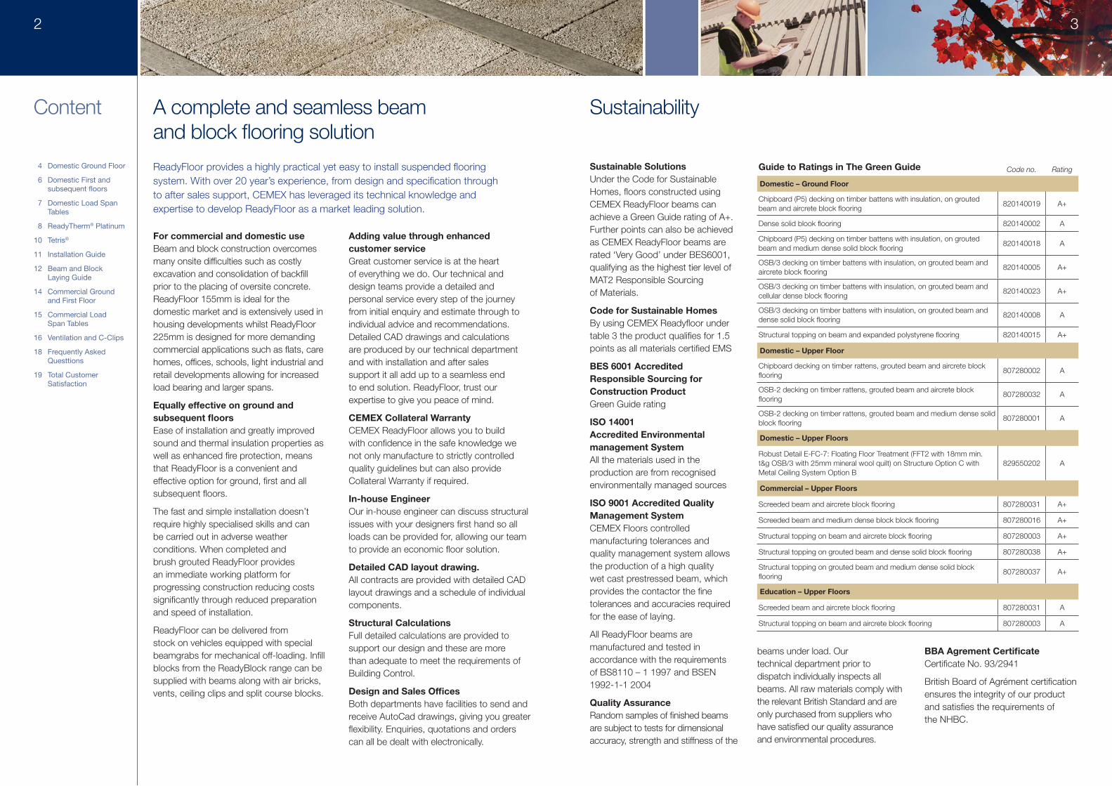
Sustainable SolutionsUnder the Code for Sustainable Homes, floors constructed using CEMEX ReadyFloor beams can achieve a Green Guide rating of A+. Further points can also be achieved as CEMEX ReadyFloor beams are rated ‘Very Good’ under BES6001, qualifying as the highest tier level of MAT2 Responsible Sourcing of Materials.
Code for Sustainable HomesBy using CEMEX Readyfloor under table 3 the product qualifies for 1.5 points as all materials certified EMS
BES 6001 Accredited Responsible Sourcing for Construction ProductGreen Guide rating
ISO 14001 Accredited Environmental management System All the materials used in the production are from recognised environmentally managed sources
ISO 9001 Accredited Quality Management System CEMEX Floors controlled manufacturing tolerances and quality management system allows the production of a high quality wet cast prestressed beam, which provides the contactor the fine tolerances and accuracies required for the ease of laying.
All ReadyFloor beams are manufactured and tested in accordance with the requirements of BS8110 – 1 1997 and BSEN 1992-1-1 2004
Quality AssuranceRandom samples of finished beams are subject to tests for dimensional accuracy, strength and stiffness of the
beams under load. Our technical department prior to dispatch individually inspects all beams. All raw materials comply with the relevant British Standard and are only purchased from suppliers who have satisfied our quality assurance and environmental procedures.
BBA Agrement CertificateCertificate No. 93/2941
British Board of Agrément certification ensures the integrity of our product and satisfies the requirements of the NHBC.
Guide to Ratings in The Green Guide Code no. Rating
Domestic – Ground Floor
Chipboard (P5) decking on timber battens with insulation, on grouted beam and aircrete block flooring
820140019 A+
Dense solid blook flooring 820140002 A
Chipboard (P5) decking on timber battens with insulation, on grouted beam and medium dense solid block flooring
820140018 A
OSB/3 decking on timber battens with insulation, on grouted beam and aircrete block flooring
820140005 A+
OSB/3 decking on timber battens with insulation, on grouted beam and cellular dense block flooring
820140023 A+
OSB/3 decking on timber battens with insulation, on grouted beam and dense solid block flooring
820140008 A
Structural topping on beam and expanded polystyrene flooring 820140015 A+
Domestic – Upper Floor
Chipboard decking on timber rattens, grouted beam and aircrete block flooring
807280002 A
OSB-2 decking on timber rattens, grouted beam and aircrete block flooring
807280032 A
OSB-2 decking on timber rattens, grouted beam and medium dense solid block flooring
807280001 A
Domestic – Upper Floors
Robust Detail E-FC-7: Floating Floor Treatment (FFT2 with 18mm min. t&g OSB/3 with 25mm mineral wool quilt) on Structure Option C with Metal Ceiling System Option B
829550202 A
Commercial – Upper Floors
Screeded beam and aircrete block flooring 807280031 A+
Screeded beam and medium dense block block flooring 807280016 A+
Structural topping on beam and aircrete block flooring 807280003 A+
Structural topping on grouted beam and dense solid block flooring 807280038 A+
Structural topping on grouted beam and medium dense solid block flooring
807280037 A+
Education – Upper Floors
Screeded beam and aircrete block flooring 807280031 A
Structural topping on beam and aircrete block flooring 807280003 A
ReadyFloor provides a highly practical yet easy to install suspended flooring system. With over 20 year’s experience, from design and specification through to after sales support, CEMEX has leveraged its technical knowledge and expertise to develop ReadyFloor as a market leading solution.
2 3
Sustainability
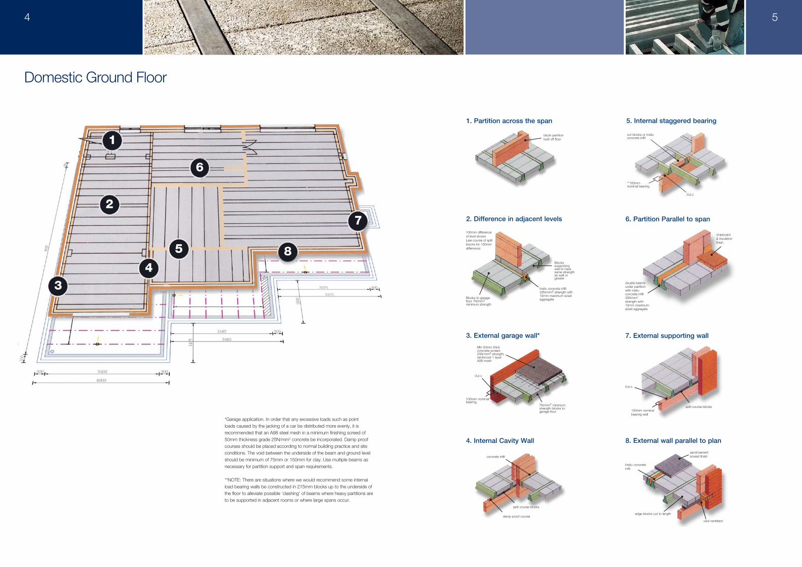
6. Partition Parallel to span
chipboard & insulation finish
double beams under partition with insitu concrete infill 30N/mm
2
strength with 10mm maximum sized aggregate
void ventilator
edge blocks cut to length
Insitu concrete infill
8. External wall parallel to plan
sand/cement screed finish
d.p.c
7. External supporting wall
100mm nominal bearing wall
split course blocks
1. Partition across the span
block partition built off floor
cut blocks or insitu concrete infill
d.p.c
**100mm nominal bearing
5. Internal staggered bearing
d.p.c
100mm nominal bearing
Min 50mm thick concrete screed 25N/mm2 strength, reinforced 1 layer A98 mesh
7N/mm2 minimum strength blocks to garage floor
3. External garage wall*
4. Internal Cavity Wall
concrete infill
damp proof course
split course blocks
Blocks to garage floor 7N/mm2 minimum strength
Insitu concrete infill 30N/mm2 strength with 10mm maximum sized aggregate
Blocks supporting wall to have same strength as wall or greater
100mm difference of level shown (use course of split blocks for 150mm difference)
2. Difference in adjacent levels
1
2
34
5
6
8
7
*Garage application. In order that any excessive loads such as point loads caused by the jacking of a car be distributed more evenly, it is recommended that an A98 steel mesh in a minimum finishing screed of 50mm thickness grade 25N/mm2 concrete be incorporated. Damp proof courses should be placed according to normal building practice and site conditions. The void between the underside of the beam and ground level should be minimum of 75mm or 150mm for clay. Use multiple beams as necessary for partition support and span requirements.
**NOTE: There are situations where we would recommend some internal load bearing walls be constructed in 215mm blocks up to the underside of the floor to alleviate possible ‘clashing’ of beams where heavy partitions are to be supported in adjacent rooms or where large spans occur.
Domestic Ground Floor
4 5
Detail of steelwork support
75mm nominal
insitu concrete fill
75mm nominal
75mm nominal
5mm minimum clearance
Detail of steelwork support
edge beam
d.p.c
100mm nominal bearing
Support on insitu concrete edge beams
75mm nominal bearing
Bearing on steel ledger angle
Domestic First Floor and subsequent floors Load Span Tables Domestic Ground and First Floors
Readyfloor® has additional benefits when used at first and subsequent floor levels, these include:
• Considerably enhanced fire protection• Improved sound insulation• Concrete floors do not ‘squeak’ with
movement• Greater floor span capability allows improved
design flexibility• Allows for block partitions to be built at first
floor level• Allows for flexibility of room layout• Ideally suited for underfloor heating• Floors independently tested to achieve 40dB
as required by Approved Document E.• Ceiling clips: 5 per m2
• Suitable cost-effective alternative to Hollowcore
First Floor : Part E Separating FloorFull Robust Detail status has been achieved for beam and block for use in separating floors, These details can be used as an alternative to Pre Completion Testing as required under the Part E Approved Document.
The specifications include both a screed finish and a timber floating floor finish. Full technical details are available from Robust Details Ltd upon registration.
CEMEX Floors is able to supply a profile block to be used in the Robust Detail specification.
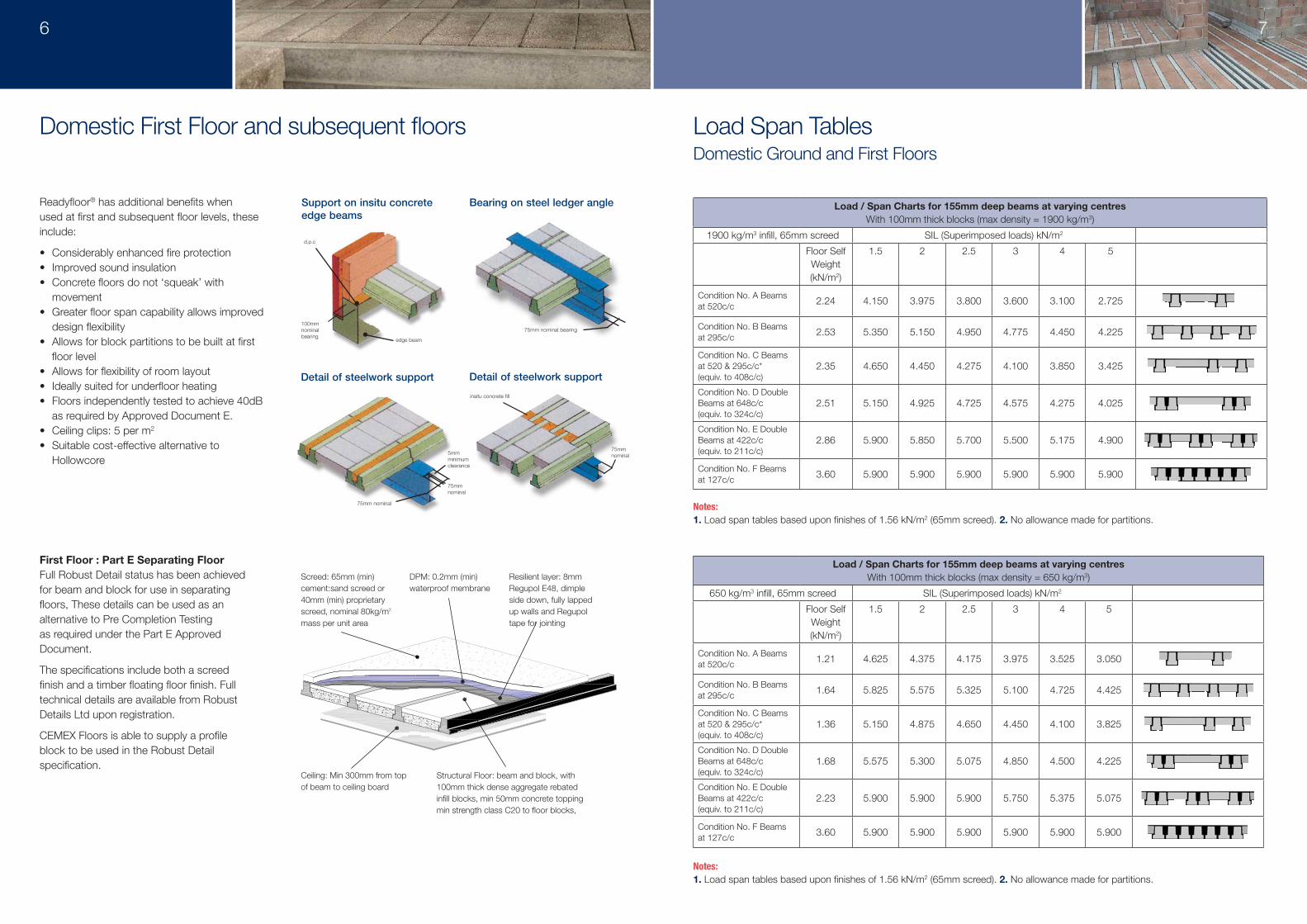
Load / Span Charts for 155mm deep beams at varying centres With 100mm thick blocks (max density = 1900 kg/m3)
1900 kg/m3 infill, 65mm screed SIL (Superimposed loads) kN/m2
Floor Self Weight (kN/m2)
1.5 2 2.5 3 4 5
Condition No. A Beams at 520c/c 2.24 4.150 3.975 3.800 3.600 3.100 2.725
Condition No. B Beams at 295c/c 2.53 5.350 5.150 4.950 4.775 4.450 4.225
Condition No. C Beams at 520 & 295c/c* (equiv. to 408c/c)
2.35 4.650 4.450 4.275 4.100 3.850 3.425
Condition No. D Double Beams at 648c/c (equiv. to 324c/c)
2.51 5.150 4.925 4.725 4.575 4.275 4.025
Condition No. E Double Beams at 422c/c (equiv. to 211c/c)
2.86 5.900 5.850 5.700 5.500 5.175 4.900
Condition No. F Beams at 127c/c 3.60 5.900 5.900 5.900 5.900 5.900 5.900
Load / Span Charts for 155mm deep beams at varying centres With 100mm thick blocks (max density = 650 kg/m3)
650 kg/m3 infill, 65mm screed SIL (Superimposed loads) kN/m2
Floor Self Weight (kN/m2)
1.5 2 2.5 3 4 5
Condition No. A Beams at 520c/c 1.21 4.625 4.375 4.175 3.975 3.525 3.050
Condition No. B Beams at 295c/c 1.64 5.825 5.575 5.325 5.100 4.725 4.425
Condition No. C Beams at 520 & 295c/c* (equiv. to 408c/c)
1.36 5.150 4.875 4.650 4.450 4.100 3.825
Condition No. D Double Beams at 648c/c (equiv. to 324c/c)
1.68 5.575 5.300 5.075 4.850 4.500 4.225
Condition No. E Double Beams at 422c/c (equiv. to 211c/c)
2.23 5.900 5.900 5.900 5.750 5.375 5.075
Condition No. F Beams at 127c/c 3.60 5.900 5.900 5.900 5.900 5.900 5.900
6 7
Screed: 65mm (min) cement:sand screed or 40mm (min) proprietary screed, nominal 80kg/m2 mass per unit area
DPM: 0.2mm (min) waterproof membrane
Resilient layer: 8mm Regupol E48, dimple side down, fully lapped up walls and Regupol tape for jointing
Structural Floor: beam and block, with 100mm thick dense aggregate rebated infill blocks, min 50mm concrete topping min strength class C20 to floor blocks, min 300kg/m2 combined mass per unit area
Ceiling: Min 300mm from top of beam to ceiling board
Notes:1. Load span tables based upon finishes of 1.56 kN/m2 (65mm screed). 2. No allowance made for partitions.
Notes:1. Load span tables based upon finishes of 1.56 kN/m2 (65mm screed). 2. No allowance made for partitions.
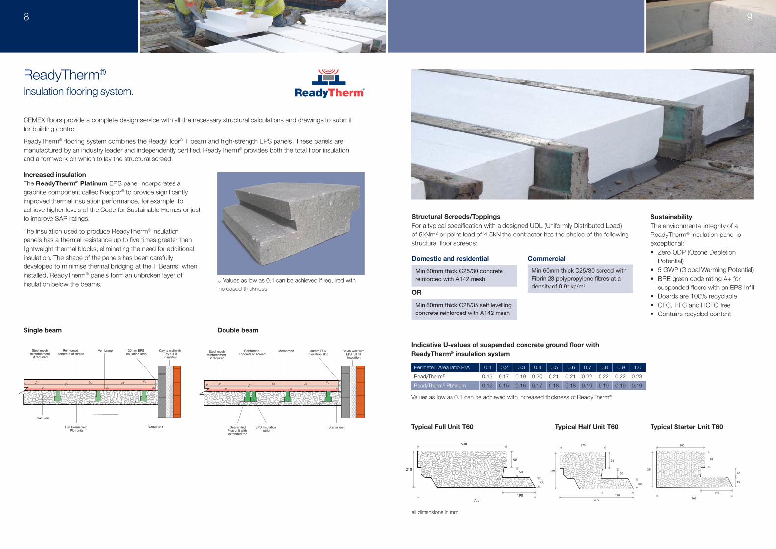
CEMEX fl oors provide a complete design service with all the necessary structural calculations and drawings to submit for building control.
ReadyTherm® fl ooring system combines the ReadyFloor® T beam and high-strength EPS panels. These panels are manufactured by an industry leader and independently certifi ed. ReadyTherm® provides both the total fl oor insulation and a formwork on which to lay the structural screed.
Increased insulationThe ReadyTherm® Platinum EPS panel incorporates a graphite component called Neopor® to provide signifi cantly improved thermal insulation performance, for example, to achieve higher levels of the Code for Sustainable Homes or just to improve SAP ratings.
The insulation used to produce ReadyTherm® insulation panels has a thermal resistance up to fi ve times greater than lightweight thermal blocks, eliminating the need for additional insulation. The shape of the panels has been carefully developed to minimise thermal bridging at the T Beams; when installed, ReadyTherm® panels form an unbroken layer of insulation below the beams.
SustainabilityThe environmental integrity of a ReadyTherm® Insulation panel is exceptional: • Zero ODP (Ozone Depletion
Potential)• 5 GWP (Global Warming Potential)• BRE green code rating A+ for
suspended fl oors with an EPS Infi ll• Boards are 100% recyclable• CFC, HFC and HCFC free• Contains recycled content
Structural Screeds/ToppingsFor a typical specifi cation with a designed UDL (Uniformly Distributed Load) of 5kNm2 or point load of 4.5kN the contractor has the choice of the following structural fl oor screeds:
Commercial
Min60mmthickC25/30screedwithFibrin23polypropylenefibresatadensityof0.91kg/m3
Domestic and residential
Min60mmthickC25/30concretereinforcedwithA142mesh
Min60mmthickC28/35selflevellingconcretereinforcedwithA142mesh
OR
Perimeter: Area ratio P/A 0.1 0.2 0.3 0.4 0.5 0.6 0.7 0.8 0.9 1.0
ReadyTherm® 0.13 0.17 0.19 0.20 0.21 0.21 0.22 0.22 0.22 0.23
ReadyTherm® Platinum 0.12 0.15 0.16 0.17 0.18 0.18 0.19 0.19 0.19 0.19
Indicative U-values of suspended concrete ground fl oor with ReadyTherm® insulation system
Values as low as 0.1 can be achieved with increased thickness of ReadyTherm®
30mm EPSinsulation strip
Reinforced concrete or screed
MembraneSteel mesh reinforcement if required
Cavity wall with EPS full fill insulation
Full Beamshield Plus units
Half unit
Starter unit
30mm EPSinsulation strip
Reinforced concrete or screed
MembraneSteel mesh reinforcement if required
Cavity wall with EPS full fill insulation
Starter unitEPS insulation strip
BeanshiledPlus unit with extended toe
30mm EPSinsulation strip
Reinforced concrete or screed
MembraneSteel mesh reinforcement if required
Cavity wall with EPS full fill insulation
Full Beamshield Plus units
Half unit
Starter unit
30mm EPSinsulation strip
Reinforced concrete or screed
MembraneSteel mesh reinforcement if required
Cavity wall with EPS full fill insulation
Starter unitEPS insulation strip
BeanshiledPlus unit with extended toe
ReadyTherm®
Insulation fl ooring system.
Single beam Double beam
U Values as low as 0.1 can be achieved if required with increased thickness
540
705
190
60
60
98
218
540
705
190
55
80
100
235
270
435
190
60
60
98
218 218
465
190
60
60
98
300
235
100
80
55
190
435
270
100
80
55
190
465
235
300
Typical Full Unit T80 Typical Half Unit T80 Typical Starter Unit T80
Typical Full Unit T60 Typical Half Unit T60 Typical Starter Unit T60
540
705
190
60
60
98
218
540
705
190
55
80
100
235
270
435
190
60
60
98
218 218
465
190
60
60
98
300
235
100
80
55
190
435
270
100
80
55
190
465
235
300
Typical Full Unit T80 Typical Half Unit T80 Typical Starter Unit T80
Typical Full Unit T60 Typical Half Unit T60 Typical Starter Unit T60
540
705
190
60
60
98
218
540
705
190
55
80
100
235
270
435
190
60
60
98
218 218
465
190
60
60
98
300
235
100
80
55
190
435
270
100
80
55
190
465
235
300
Typical Full Unit T80 Typical Half Unit T80 Typical Starter Unit T80
Typical Full Unit T60 Typical Half Unit T60 Typical Starter Unit T60Typical Full Unit T60 Typical Half Unit T60 Typical Starter Unit T60
all dimensions in mm
8 9

PreparationThe use of ReadyFloor® considerably reduces site preparation and thus only the removal of top soil and any vegetable matter is required. No oversite concrete or additional surface seal is necessary. Provision of a void between the underside of the floor and the ground level of at least 75mm (150mm for clay) and 150mm in Scotland. If the site is liable to flooding then subvoid drainage may be required.
ReadyFloor® seldom requires an increase in foundation size, however if the ground condition is very poor, specialist advice should be sought.
HandlingReadyFloor® beams should only be lifted when supported near the ends of the units, taking particular care with beams over 3m in length. Beams must only be lifted in an upright position. The approximate self weights of beams are: 155mm - 36kg/m; 225mm - 66kg/m.
StackingIn order to prevent damage to beams, they should be stacked on battens on a hard level surface. Battens must be placed near the ends of the beams and in line with each other throughout the height of the stack.
InstallationThe bearings for the beams should be clean, level and free from debris. The mortar in the masonry must be cured and have sufficient strength to support the floor.
A continuous damp-proof course should be laid along the support wall below the floor in accordance with CP 102 : 1973.
For masonry construction the beams should have a nominal bearing of 100mm. Where supported by steel the nominal bearing can be reduced to 75mm. In cavity construction, beams should not project into the cavity.
Tetris® Installation Guide
Where two or more beams are placed side by side, the space between the beams above the flanges must be filled with insitu concrete of minimum compressive strength 30N/mm2 with 10mm maximum sized aggregate. The concrete must be allowed to cure to the necessary strength before loads, such as partition walls, are applied.
The beam shall not be worked on site in any way ie, by drilling, notching, cutting or in any other manner, without the permission of CEMEX Floors. Place floor beams at the centres shown on the drawing, positioning infill blocks between the extreme ends of the beams as work progresses in order to ensure the correct spacing.
GroutingA 1:4 cement sand slurry mix grout should be well brushed into the floor. Prior to grouting, the floor should be thoroughly cleaned and wetted to ensure effective seal.
SafetyNote, that prior to grouting, the floor does not form a safe working platform and where barrow or bogie runs are required plywood or scaffold boards must span
between beams at all times. Throughout construction any loads imposed on the floor, such as those from stored materials etc, should be minimised and in any event must be short term and not exceed the load for which the floor was designed.
When ReadyFloor® beams are used at upper floor all necessary care and attention should be given to provide a safe working platform as noted in the Precast Flooring Federation Code of Practice for the safe erection of precast flooring and associated components.
Fire ResistanceReadyFloor® is capable of achieving a half hour fire rating with 155mm beams and one hour with 225mm beams.
Floor FinishesThe three alternatives below are typical of various finishes which can be applied. The quality of materials, and work manship are set out in the appropriate British Standards.
A.SandCementScreedfinish50mmSand/Cementscreed
18tongueandgroovedChipboard
Vapourbarrier
Vapourbarrier
Suitableinsulation
Galvanisedhangarsin1stfloorsforceilingattachment
65mmScreed
Appropriateinsulation
ReadyFloor®
ReadyFloor®
ReadyFloor®
C.Screedandinsulationfinish
B.ChipboardandInsulationfinish
1
1
2
3
4
5
7
6
7
8
9
10
11
7
11
9 8
4
52
3
610
TETRIS® T600 block
TETRIS® T300 block
TETRIS® Gap strip (supplied 600mm wide and cut to size on site)
TETRIS® Gap strip (supplied pre-cut to suit 1/2 the width of the beam used)
TETRIS® Vertical edge strip (supplied to suit the depth of the concrete finish)
CEMEX® pre-stressed concrete floor beam
Closer block to suit T300/T600
Slip course
Masonry block (cut to suit)
Damp proof course
Structural concrete floor finish
Ene 1
Typical U-value
0.10 - 0.21 W/m2K
Mat 1
Element N
Green Guide rating A+
Code credits* 3
820140051
Pol 1
GWP value <5 <5
Code credits* 1 0
TETRIS®TETRIS®
THE CODE FORSUSTAINABLE
HOMES
Tetris® is a unique patented thermal insulation floor system, designed to provide outstanding thermal and structural performance.
The system consists of large, lightweight, ultra high compressive strength insulation blocks which sit on and between CEMEX ReadyFloor® concrete floor beams. The blocks and then covered with a structural concrete topping to produce a super insulated floor with the highest possible Green Guide rating available of A+.
Benefits of the Tetris Flooring System• Faster floor construction (up to 16x less
blocks to install)• Supplied to site in floor specific
quantities• Reduces the amount of concrete
required• Produces a floor with zero cold bridging• Is a BRE Green Guide A+ rated system• 3 Code* credits awarded• 100% recyclable• Cost effective
• Fixes floor height above the beams at 150mm
• Easily incorporates underfloor heating system
• Able to withstand foot traffic during the construction process
• Insulation integrity guaranteed• Accredited construction detail• 2010 Part L solution• U-values as low as 0.10 W/m2K
* Code credits quoted are subject to an approximate weighted vaue
10 11
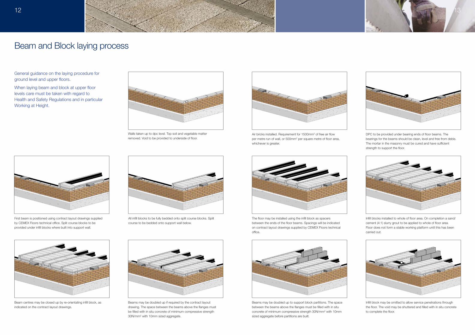
General guidance on the laying procedure for ground level and upper fl oors.
When laying beam and block at upper fl oor levels care must be taken with regard to Health and Safety Regulations and in particular Working at Height.
Walls taken up to dpc level. Top soil and vegetable matter removed. Void to be provided to underside of fl oor.
First beam is positioned using contract layout drawings supplied by CEMEX Floors technical offi ce. Split course blocks to be provided under infi ll blocks where built into support wall.
Beam centres may be closed up by re-orientating infi ll block, as indicated on the contract layout drawings.
Beams may be doubled up if required by the contract layout drawing. The space between the beams above the fl anges must be fi lled with in situ concrete of minimum compressive strength 30N/mm2 with 10mm sized aggregate.
Beams may be doubled up to support block partitions. The space between the beams above the fl anges must be fi lled with in situ concrete of minimum compressive strength 30N/mm2 with 10mm sized aggregate before partitions are built.
Infi ll block may be omitted to allow service penetrations through the fl oor. The void may be shuttered and fi lled with in situ concrete to complete the fl oor.
All infi ll blocks to be fully bedded onto split course blocks. Split course to be bedded onto support wall below.
The fl oor may be installed using the infi ll block as spacers between the ends of the fl oor beams. Spacings will be indicated on contract layout drawings supplied by CEMEX Floors technical offi ce.
Infi ll blocks installed to whole of fl oor area. On completion a sand/cement (4:1) slurry grout to be applied to whole of fl oor area. Floor does not form a stable working platform until this has been carried out.
Air bricks installed. Requirement for 1500mm2 of free air fl ow per metre run of wall, or 500mm2 per square metre of fl oor area, whichever is greater.
DPC to be provided under bearing ends of fl oor beams. The bearings for the beams should be clean, level and free from debis. The mortar in the masonry must be cured and have suffi cient strength to support the fl oor.
Beam and Block laying process
12 13
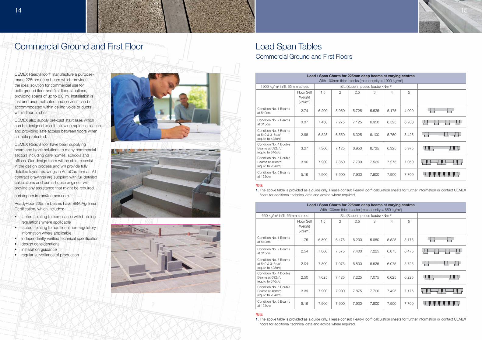
Load Span TablesCommercial Ground and First Floors
Load / Span Charts for 225mm deep beams at varying centresWith 100mm thick blocks (max density = 1900 kg/m3)
1900 kg/m3 infi ll, 65mm screed SIL (Superimposed loads) kN/m2
Floor Self Weight(kN/m2)
1.5 2 2.5 3 4 5
Condition No. 1 Beams at 540crs 2.74 6.200 5.950 5.725 5.525 5.175 4.900
Condition No. 2 Beams at 315crs 3.37 7.450 7.275 7.125 6.950 6.525 6.200
Condition No. 3 Beams at 540 & 315c/c* (equiv. to 428c/c)
2.98 6.825 6.550 6.325 6.100 5.750 5.425
Condition No. 4 Double Beams at 692c/c(equiv. to 346c/c)
3.27 7.300 7.125 6.950 6.725 6.325 5.975
Condition No. 5 Double Beams at 468c/c(equiv. to 234c/c)
3.96 7.900 7.850 7.700 7.525 7.275 7.050
Condition No. 6 Beams at 152c/c 5.16 7.900 7.900 7.900 7.900 7.900 7.700
Load / Span Charts for 225mm deep beams at varying centresWith 100mm thick blocks (max density = 650 kg/m3)
650 kg/m3 infi ll, 65mm screed SIL (Superimposed loads) kN/m2
Floor Self Weight(kN/m2)
1.5 2 2.5 3 4 5
Condition No. 1 Beams at 540crs 1.75 6.800 6.475 6.200 5.950 5.525 5.175
Condition No. 2 Beams at 315crs 2.54 7.800 7.575 7.400 7.225 6.875 6.475
Condition No. 3 Beams at 540 & 315c/c* (equiv. to 428c/c)
2.04 7.300 7.075 6.800 6.525 6.075 5.725
Condition No. 4 Double Beams at 692c/c(equiv. to 346c/c)
2.50 7.625 7.425 7.225 7.075 6.625 6.225
Condition No. 5 Double Beams at 468c/c(equiv. to 234c/c)
3.39 7.900 7.900 7.875 7.700 7.425 7.175
Condition No. 6 Beams at 152c/c 5.16 7.900 7.900 7.900 7.900 7.900 7.700
CEMEX ReadyFloor® manufacture a purpose-made 225mm deep beam which provides the ideal solution for commercial use for both ground fl oor and fi rst fl oor situations, providing spans of up to 8.0 lm. Installation is fast and uncomplicated and services can be accommodated within ceiling voids or ducts within fl oor fi nishes.
CEMEX also supply pre-cast staircases which can be designed to suit, allowing rapid installation and providing safe access between fl oors when suitable protected.
CEMEX ReadyFloor have been supplying beam and block solutions to many commercial sectors including care homes, schools and offi ces. Our design team will be able to assist in the design process and will provide fully detailed layout drawings in AutoCad format. All contract drawings are supplied with full detailed calculations and our in-house engineer will provide any assistance that might be required.
ReadyFloor 225mm beams have BBA Agrément Certifi cation, which includes:
• factors relating to compliance with building regulations where applicable
• factors relating to additional non-regulatory information where applicable
• independently verifi ed technical specifi cation• design considerations• installation guidance• regular surveillance of production
Commercial Ground and First Floor
14 15
Note:1. The above table is provided as a guide only. Please consult ReadyFloor® calculation sheets for further information or contact CEMEX
fl oors for additional technical data and advice where required.
Note:1. The above table is provided as a guide only. Please consult ReadyFloor® calculation sheets for further information or contact CEMEX
fl oors for additional technical data and advice where required.
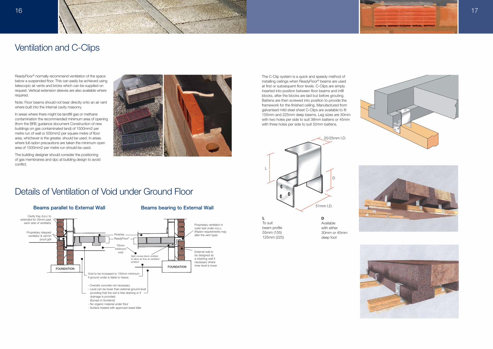
The C-Clip system is a quick and speedy method of installing ceilings when ReadyFloor® beams are used at first or subsequent floor levels. C-Clips are simply inserted into position between floor beams and infill blocks, after the blocks are laid but before grouting. Battens are then screwed into position to provide the framework for the finished ceiling. Manufactured from galvanised mild steel sheet C-Clips are available to fit 155mm and 225mm deep beams. Leg sizes are 30mm with two holes per side to suit 38mm battens or 45mm with three holes per side to suit 52mm battens.
20/25mm I.D.
D
L
51mm I.D.
DAvailablewith either30mm or 45mmdeep foot
LTo suit beam profile55mm (155)125mm (225)
ReadyFloor® normally recommend ventilation of the space below a suspended floor. This can easily be achieved using telescopic air vents and bricks which can be supplied on request. Vertical extension sleeves are also available where required.
Note: Floor beams should not bear directly onto an air vent where built into the internal cavity masonry.
In areas where there might be landfill gas or methane contamination the recommended minimum area of opening (from the BRE guidance document Construction of new buildings on gas contaminated land) of 1500mm2 per metre run of wall or 500mm2 per square metre of floor area, whichever is the greater, should be used. In areas where full radon precautions are taken the minimum open area of 1500mm2 per metre run should be used.
The building designer should consider the positioning of gas membranes and dpc at building design to avoid conflict.
Ventilation and C-Clips
Details of Ventilation of Void under Ground Floor
FOUNDATIONFOUNDATION
Beams parallel to External Wall Beams bearing to External Wall
Proprietary stepped ventilator & vermin
proof grill
Void to be increased to 150mm minimum if ground under is liable to heave.
- Oversite concrete not necessary- Level can be lower than external ground level providing that the soil is free draining or if drainage is provided. (Except in Scotland)- No organic material under floor- Surface treated with approved weed killer
FinishesReadyFloor®
75mm minimum
voidSplit course block omitted to allow air flow at ventilator position
Proprietary ventilator in outer leaf under d.p.c.(Radon requirements may alter the vent type)
External wall to be designed as a retaining wall if necessary where inner level is lower
Cavity tray d.p.c to extended for 25mm past
each side of ventilator
16 17
Frequently Asked Questions Total Customer Satisfaction
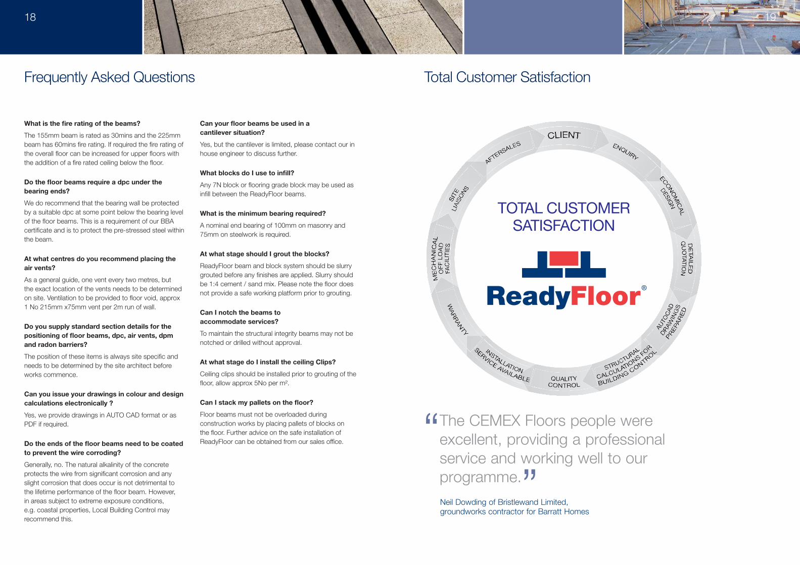
“ The CEMEX Floors people were excellent, providing a professional service and working well to our programme.”
18 19
TOTAL CUSTOMERSATISFACTION
Neil Dowding of Bristlewand Limited, groundworks contractor for Barratt Homes
What is the fi re rating of the beams?
The 155mm beam is rated as 30mins and the 225mm beam has 60mins fi re rating. If required the fi re rating of the overall fl oor can be increased for upper fl oors with the addition of a fi re rated ceiling below the fl oor.
Do the fl oor beams require a dpc under the bearing ends?
We do recommend that the bearing wall be protected by a suitable dpc at some point below the bearing level of the fl oor beams. This is a requirement of our BBA certifi cate and is to protect the pre-stressed steel within the beam.
At what centres do you recommend placing the air vents?
As a general guide, one vent every two metres, but the exact location of the vents needs to be determined on site. Ventilation to be provided to fl oor void, approx 1 No 215mm x75mm vent per 2m run of wall.
Do you supply standard section details for the positioning of fl oor beams, dpc, air vents, dpm and radon barriers?
The position of these items is always site specifi c and needs to be determined by the site architect before works commence.
Can you issue your drawings in colour and design calculations electronically ?
Yes, we provide drawings in AUTO CAD format or as PDF if required.
Do the ends of the fl oor beams need to be coated to prevent the wire corroding?
Generally, no. The natural alkalinity of the concrete protects the wire from signifi cant corrosion and any slight corrosion that does occur is not detrimental to the lifetime performance of the fl oor beam. However, in areas subject to extreme exposure conditions, e.g. coastal properties, Local Building Control may recommend this.
Can your fl oor beams be used in a cantilever situation?
Yes, but the cantilever is limited, please contact our in house engineer to discuss further.
What blocks do I use to infi ll?
Any 7N block or fl ooring grade block may be used as infi ll between the ReadyFloor beams.
What is the minimum bearing required?
A nominal end bearing of 100mm on masonry and 75mm on steelwork is required.
At what stage should I grout the blocks?
ReadyFloor beam and block system should be slurry grouted before any fi nishes are applied. Slurry should be 1:4 cement / sand mix. Please note the fl oor does not provide a safe working platform prior to grouting.
Can I notch the beams to accommodate services?
To maintain the structural integrity beams may not be notched or drilled without approval.
At what stage do I install the ceiling Clips?
Ceiling clips should be installed prior to grouting of the fl oor, allow approx 5No per m².
Can I stack my pallets on the fl oor?
Floor beams must not be overloaded during construction works by placing pallets of blocks on the fl oor. Further advice on the safe installation of ReadyFloor can be obtained from our sales offi ce.
CEMEX UK Building Products LtdLondon Road, Wick, Bristol BS30 5SJ Tel 01179 373740
For more information contact our Readyfloor Helpline Tel 0800 667 827 Email: [email protected] www.cemex.co.uk