bclp nutshell
DESCRIPTION
BCLP NutshellTRANSCRIPT

BCLP in a Nutshell
Study Guide for Exam
150-420
Exam Preparation Materials
Revision August 2010
Corporate Headquarters - San Jose, CA USAT: (408) [email protected]
European Headquarters - Geneva, SwitzerlandT: +41 22 799 56 [email protected]
Asia Pacific Headquarters - SingaporeT: [email protected]
© 2010 Brocade Communications Systems, Inc. All Rights Reserved.
Brocade, the Brocade B-weave logo, Fabric OS, File Lifecycle Manager, MyView, Secure Fabric OS, SilkWorm, and StorageX are registered trademarks and the Brocade B-wing symbol and Tapestry are trademarks of Brocade Communications Systems, Inc., in the United States and/or in other countries. FICON is a registered trademark of IBM Corporation in the U.S. and other countries. All other brands, products, or service names are or may be trademarks or service marks of, and are used to identify, products or services of their respective owners.
Notice: This document is for informational purposes only and does not set forth any warranty, expressed or implied, concerning any equipment, equipment feature, or service offered or to be offered by Brocade. Brocade reserves the right to make changes to this document at any time, without notice, and assumes no responsibility for its use. This informational document describes features that may not be currently available. Contact a Brocade sales office for information on feature and product availability. Export of technical data contained in this document may require an export license from the United States government.
Revision: August 2010
©2010 Brocade Communications i
Brocade Certified Layer 4-7 Professional in a Nutshell First Edition
Objective: The BCLP Nutshell guide is designed to help you prepare for the BCLP Certification, exam number 150-420.
Audience: The BCLP Nutshell self-study guide is intended for those who have successfully completed the CLP 240 ADX Advanced Techniques in Sever Load Balancing Certified Layer 4-7 Professional Revision course, and who wish to undertake self-study or review activities before taking the actual BCLP exam. The BCLP guide is not intended as a substitute for classroom training or hands-on time with Brocade products.
How to make the most of the BCLP guide: The BCLP guide summarizes the key topics on the BCLP exam for you in an easy to use format. It is organized closely around the exam objectives. We suggest this guide be used in conjunction with our free online knowledge assessment test. To benefit from the BCLP guide, we strongly recommend you have successfully completed the CLP 240 ADX Advanced Techniques in Sever Load Balancing Certified Layer 4-7 course.
We hope you find this useful in your journey towards BCLP Certification, and we welcome your feedback by sending an email to [email protected].
Helen Lautenschlager Joe CannataDirector of Education Solutions Certification Manager
BCLP in a Nutshell First Edition

Brocade Certified Layer 4-7 Professional in a Nutshell First Edition
ii ©2010 Brocade Communications
©2010 Brocade Communications iii
Brocade Certified Layer 4-7 Professional in a Nutshell First Edition
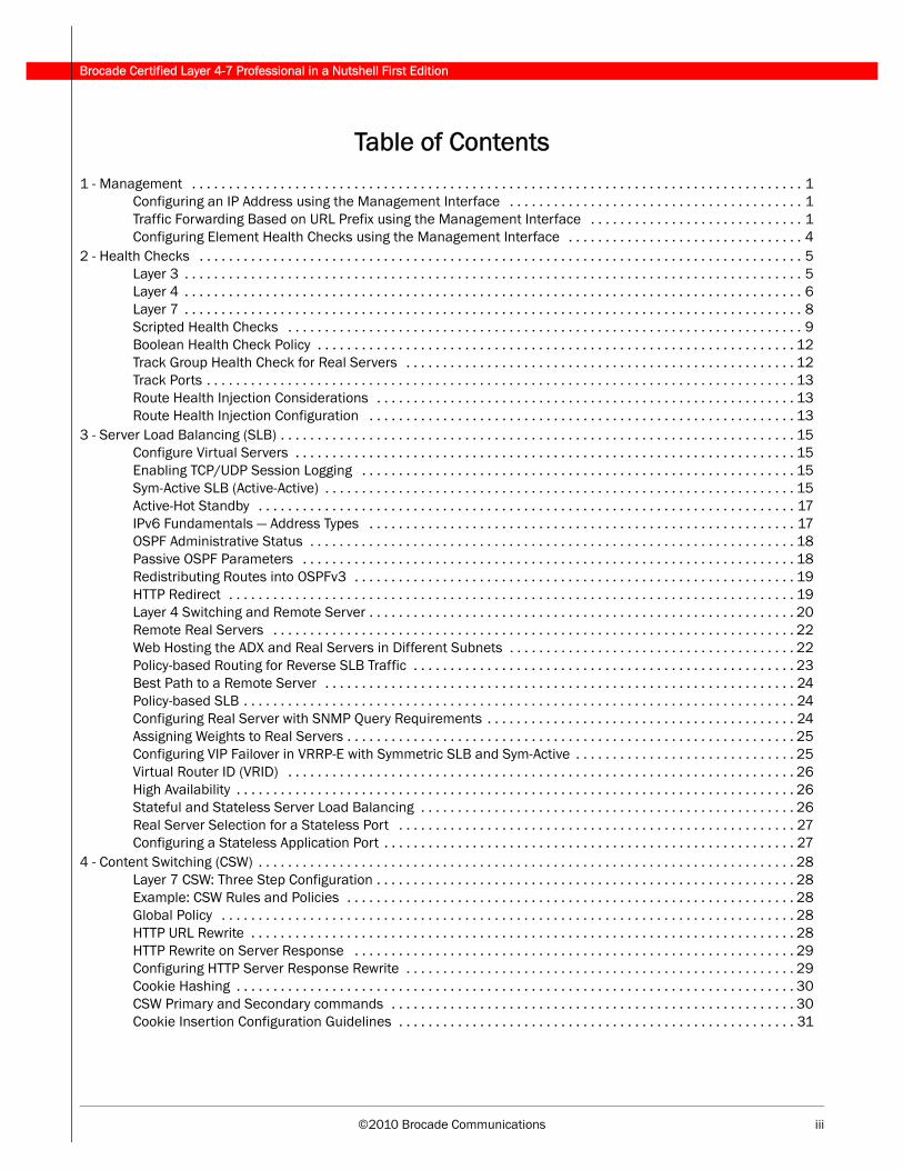
Table of Contents1 - Management . . . . . . . . . . . . . . . . . . . . . . . . . . . . . . . . . . . . . . . . . . . . . . . . . . . . . . . . . . . . . . . . . . . . . . . . . . . . . . . . . . . 1
Configuring an IP Address using the Management Interface . . . . . . . . . . . . . . . . . . . . . . . . . . . . . . . . . . . . . . . . 1Traffic Forwarding Based on URL Prefix using the Management Interface . . . . . . . . . . . . . . . . . . . . . . . . . . . . . 1Configuring Element Health Checks using the Management Interface . . . . . . . . . . . . . . . . . . . . . . . . . . . . . . . . 4
2 - Health Checks . . . . . . . . . . . . . . . . . . . . . . . . . . . . . . . . . . . . . . . . . . . . . . . . . . . . . . . . . . . . . . . . . . . . . . . . . . . . . . . . . . 5Layer 3 . . . . . . . . . . . . . . . . . . . . . . . . . . . . . . . . . . . . . . . . . . . . . . . . . . . . . . . . . . . . . . . . . . . . . . . . . . . . . . . . . . . . 5Layer 4 . . . . . . . . . . . . . . . . . . . . . . . . . . . . . . . . . . . . . . . . . . . . . . . . . . . . . . . . . . . . . . . . . . . . . . . . . . . . . . . . . . . . 6Layer 7 . . . . . . . . . . . . . . . . . . . . . . . . . . . . . . . . . . . . . . . . . . . . . . . . . . . . . . . . . . . . . . . . . . . . . . . . . . . . . . . . . . . . 8Scripted Health Checks . . . . . . . . . . . . . . . . . . . . . . . . . . . . . . . . . . . . . . . . . . . . . . . . . . . . . . . . . . . . . . . . . . . . . . 9Boolean Health Check Policy . . . . . . . . . . . . . . . . . . . . . . . . . . . . . . . . . . . . . . . . . . . . . . . . . . . . . . . . . . . . . . . . . 12Track Group Health Check for Real Servers . . . . . . . . . . . . . . . . . . . . . . . . . . . . . . . . . . . . . . . . . . . . . . . . . . . . . 12Track Ports . . . . . . . . . . . . . . . . . . . . . . . . . . . . . . . . . . . . . . . . . . . . . . . . . . . . . . . . . . . . . . . . . . . . . . . . . . . . . . . . 13Route Health Injection Considerations . . . . . . . . . . . . . . . . . . . . . . . . . . . . . . . . . . . . . . . . . . . . . . . . . . . . . . . . . 13Route Health Injection Configuration . . . . . . . . . . . . . . . . . . . . . . . . . . . . . . . . . . . . . . . . . . . . . . . . . . . . . . . . . . 13
3 - Server Load Balancing (SLB) . . . . . . . . . . . . . . . . . . . . . . . . . . . . . . . . . . . . . . . . . . . . . . . . . . . . . . . . . . . . . . . . . . . . . . 15Configure Virtual Servers . . . . . . . . . . . . . . . . . . . . . . . . . . . . . . . . . . . . . . . . . . . . . . . . . . . . . . . . . . . . . . . . . . . . 15Enabling TCP/UDP Session Logging . . . . . . . . . . . . . . . . . . . . . . . . . . . . . . . . . . . . . . . . . . . . . . . . . . . . . . . . . . . 15Sym-Active SLB (Active-Active) . . . . . . . . . . . . . . . . . . . . . . . . . . . . . . . . . . . . . . . . . . . . . . . . . . . . . . . . . . . . . . . . 15Active-Hot Standby . . . . . . . . . . . . . . . . . . . . . . . . . . . . . . . . . . . . . . . . . . . . . . . . . . . . . . . . . . . . . . . . . . . . . . . . . 17IPv6 Fundamentals — Address Types . . . . . . . . . . . . . . . . . . . . . . . . . . . . . . . . . . . . . . . . . . . . . . . . . . . . . . . . . . 17OSPF Administrative Status . . . . . . . . . . . . . . . . . . . . . . . . . . . . . . . . . . . . . . . . . . . . . . . . . . . . . . . . . . . . . . . . . . 18Passive OSPF Parameters . . . . . . . . . . . . . . . . . . . . . . . . . . . . . . . . . . . . . . . . . . . . . . . . . . . . . . . . . . . . . . . . . . . 18Redistributing Routes into OSPFv3 . . . . . . . . . . . . . . . . . . . . . . . . . . . . . . . . . . . . . . . . . . . . . . . . . . . . . . . . . . . . 19HTTP Redirect . . . . . . . . . . . . . . . . . . . . . . . . . . . . . . . . . . . . . . . . . . . . . . . . . . . . . . . . . . . . . . . . . . . . . . . . . . . . . 19Layer 4 Switching and Remote Server . . . . . . . . . . . . . . . . . . . . . . . . . . . . . . . . . . . . . . . . . . . . . . . . . . . . . . . . . . 20Remote Real Servers . . . . . . . . . . . . . . . . . . . . . . . . . . . . . . . . . . . . . . . . . . . . . . . . . . . . . . . . . . . . . . . . . . . . . . . 22Web Hosting the ADX and Real Servers in Different Subnets . . . . . . . . . . . . . . . . . . . . . . . . . . . . . . . . . . . . . . . 22Policy-based Routing for Reverse SLB Traffic . . . . . . . . . . . . . . . . . . . . . . . . . . . . . . . . . . . . . . . . . . . . . . . . . . . . 23Best Path to a Remote Server . . . . . . . . . . . . . . . . . . . . . . . . . . . . . . . . . . . . . . . . . . . . . . . . . . . . . . . . . . . . . . . . 24Policy-based SLB . . . . . . . . . . . . . . . . . . . . . . . . . . . . . . . . . . . . . . . . . . . . . . . . . . . . . . . . . . . . . . . . . . . . . . . . . . . 24Configuring Real Server with SNMP Query Requirements . . . . . . . . . . . . . . . . . . . . . . . . . . . . . . . . . . . . . . . . . . 24Assigning Weights to Real Servers . . . . . . . . . . . . . . . . . . . . . . . . . . . . . . . . . . . . . . . . . . . . . . . . . . . . . . . . . . . . . 25Configuring VIP Failover in VRRP-E with Symmetric SLB and Sym-Active . . . . . . . . . . . . . . . . . . . . . . . . . . . . . . 25Virtual Router ID (VRID) . . . . . . . . . . . . . . . . . . . . . . . . . . . . . . . . . . . . . . . . . . . . . . . . . . . . . . . . . . . . . . . . . . . . . 26High Availability . . . . . . . . . . . . . . . . . . . . . . . . . . . . . . . . . . . . . . . . . . . . . . . . . . . . . . . . . . . . . . . . . . . . . . . . . . . . 26Stateful and Stateless Server Load Balancing . . . . . . . . . . . . . . . . . . . . . . . . . . . . . . . . . . . . . . . . . . . . . . . . . . . 26Real Server Selection for a Stateless Port . . . . . . . . . . . . . . . . . . . . . . . . . . . . . . . . . . . . . . . . . . . . . . . . . . . . . . 27Configuring a Stateless Application Port . . . . . . . . . . . . . . . . . . . . . . . . . . . . . . . . . . . . . . . . . . . . . . . . . . . . . . . . 27
4 - Content Switching (CSW) . . . . . . . . . . . . . . . . . . . . . . . . . . . . . . . . . . . . . . . . . . . . . . . . . . . . . . . . . . . . . . . . . . . . . . . . . 28Layer 7 CSW: Three Step Configuration . . . . . . . . . . . . . . . . . . . . . . . . . . . . . . . . . . . . . . . . . . . . . . . . . . . . . . . . . 28Example: CSW Rules and Policies . . . . . . . . . . . . . . . . . . . . . . . . . . . . . . . . . . . . . . . . . . . . . . . . . . . . . . . . . . . . . 28Global Policy . . . . . . . . . . . . . . . . . . . . . . . . . . . . . . . . . . . . . . . . . . . . . . . . . . . . . . . . . . . . . . . . . . . . . . . . . . . . . . 28HTTP URL Rewrite . . . . . . . . . . . . . . . . . . . . . . . . . . . . . . . . . . . . . . . . . . . . . . . . . . . . . . . . . . . . . . . . . . . . . . . . . . 28HTTP Rewrite on Server Response . . . . . . . . . . . . . . . . . . . . . . . . . . . . . . . . . . . . . . . . . . . . . . . . . . . . . . . . . . . . 29Configuring HTTP Server Response Rewrite . . . . . . . . . . . . . . . . . . . . . . . . . . . . . . . . . . . . . . . . . . . . . . . . . . . . . 29Cookie Hashing . . . . . . . . . . . . . . . . . . . . . . . . . . . . . . . . . . . . . . . . . . . . . . . . . . . . . . . . . . . . . . . . . . . . . . . . . . . . 30CSW Primary and Secondary commands . . . . . . . . . . . . . . . . . . . . . . . . . . . . . . . . . . . . . . . . . . . . . . . . . . . . . . . 30Cookie Insertion Configuration Guidelines . . . . . . . . . . . . . . . . . . . . . . . . . . . . . . . . . . . . . . . . . . . . . . . . . . . . . . 31
iv ©2010 Brocade Communications
Brocade Certified Layer 4-7 Professional in a Nutshell First Edition
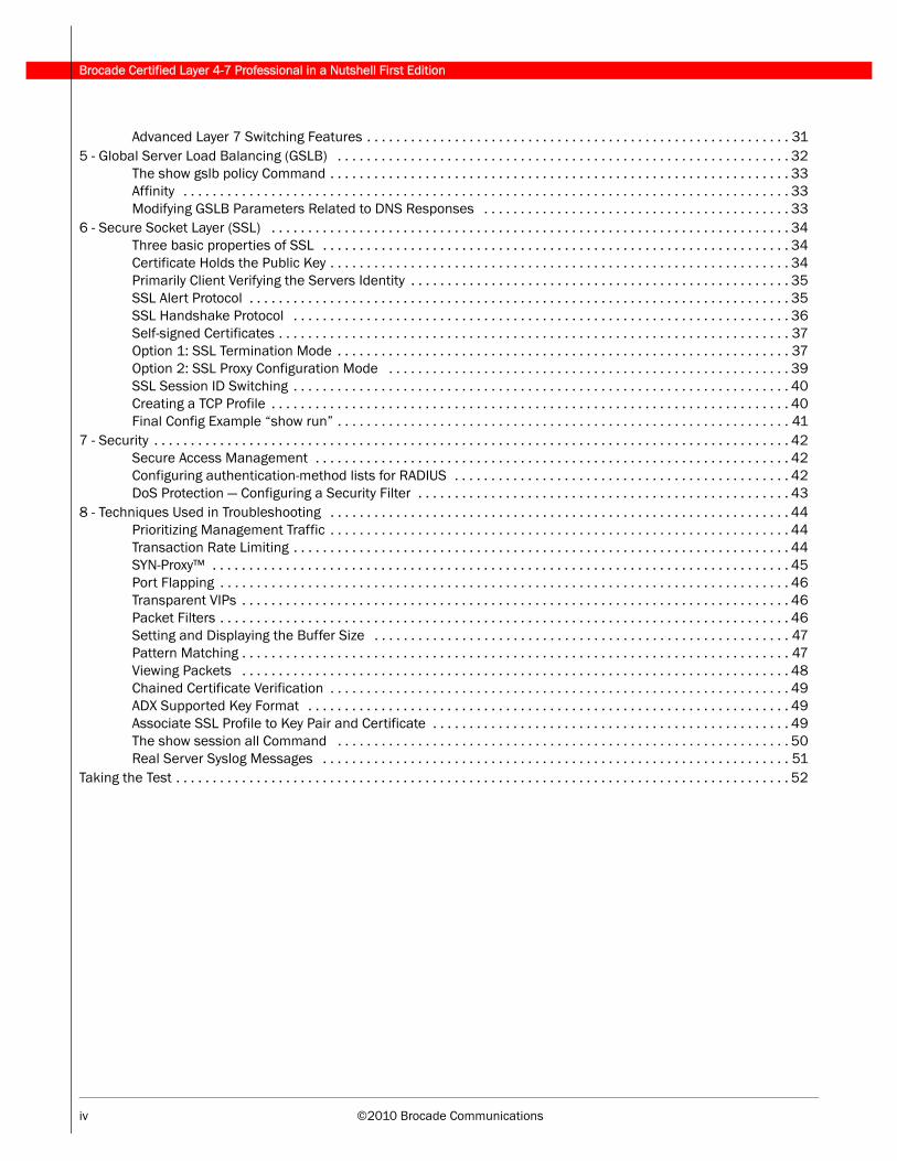
Advanced Layer 7 Switching Features . . . . . . . . . . . . . . . . . . . . . . . . . . . . . . . . . . . . . . . . . . . . . . . . . . . . . . . . . . 315 - Global Server Load Balancing (GSLB) . . . . . . . . . . . . . . . . . . . . . . . . . . . . . . . . . . . . . . . . . . . . . . . . . . . . . . . . . . . . . . 32
The show gslb policy Command . . . . . . . . . . . . . . . . . . . . . . . . . . . . . . . . . . . . . . . . . . . . . . . . . . . . . . . . . . . . . . . 33Affinity . . . . . . . . . . . . . . . . . . . . . . . . . . . . . . . . . . . . . . . . . . . . . . . . . . . . . . . . . . . . . . . . . . . . . . . . . . . . . . . . . . . 33Modifying GSLB Parameters Related to DNS Responses . . . . . . . . . . . . . . . . . . . . . . . . . . . . . . . . . . . . . . . . . . 33
6 - Secure Socket Layer (SSL) . . . . . . . . . . . . . . . . . . . . . . . . . . . . . . . . . . . . . . . . . . . . . . . . . . . . . . . . . . . . . . . . . . . . . . . 34Three basic properties of SSL . . . . . . . . . . . . . . . . . . . . . . . . . . . . . . . . . . . . . . . . . . . . . . . . . . . . . . . . . . . . . . . . 34Certificate Holds the Public Key . . . . . . . . . . . . . . . . . . . . . . . . . . . . . . . . . . . . . . . . . . . . . . . . . . . . . . . . . . . . . . . 34Primarily Client Verifying the Servers Identity . . . . . . . . . . . . . . . . . . . . . . . . . . . . . . . . . . . . . . . . . . . . . . . . . . . . 35SSL Alert Protocol . . . . . . . . . . . . . . . . . . . . . . . . . . . . . . . . . . . . . . . . . . . . . . . . . . . . . . . . . . . . . . . . . . . . . . . . . . 35SSL Handshake Protocol . . . . . . . . . . . . . . . . . . . . . . . . . . . . . . . . . . . . . . . . . . . . . . . . . . . . . . . . . . . . . . . . . . . . 36Self-signed Certificates . . . . . . . . . . . . . . . . . . . . . . . . . . . . . . . . . . . . . . . . . . . . . . . . . . . . . . . . . . . . . . . . . . . . . . 37Option 1: SSL Termination Mode . . . . . . . . . . . . . . . . . . . . . . . . . . . . . . . . . . . . . . . . . . . . . . . . . . . . . . . . . . . . . . 37Option 2: SSL Proxy Configuration Mode . . . . . . . . . . . . . . . . . . . . . . . . . . . . . . . . . . . . . . . . . . . . . . . . . . . . . . . 39SSL Session ID Switching . . . . . . . . . . . . . . . . . . . . . . . . . . . . . . . . . . . . . . . . . . . . . . . . . . . . . . . . . . . . . . . . . . . . 40Creating a TCP Profile . . . . . . . . . . . . . . . . . . . . . . . . . . . . . . . . . . . . . . . . . . . . . . . . . . . . . . . . . . . . . . . . . . . . . . . 40Final Config Example “show run” . . . . . . . . . . . . . . . . . . . . . . . . . . . . . . . . . . . . . . . . . . . . . . . . . . . . . . . . . . . . . . 41
7 - Security . . . . . . . . . . . . . . . . . . . . . . . . . . . . . . . . . . . . . . . . . . . . . . . . . . . . . . . . . . . . . . . . . . . . . . . . . . . . . . . . . . . . . . . 42Secure Access Management . . . . . . . . . . . . . . . . . . . . . . . . . . . . . . . . . . . . . . . . . . . . . . . . . . . . . . . . . . . . . . . . . 42Configuring authentication-method lists for RADIUS . . . . . . . . . . . . . . . . . . . . . . . . . . . . . . . . . . . . . . . . . . . . . . 42DoS Protection — Configuring a Security Filter . . . . . . . . . . . . . . . . . . . . . . . . . . . . . . . . . . . . . . . . . . . . . . . . . . . 43
8 - Techniques Used in Troubleshooting . . . . . . . . . . . . . . . . . . . . . . . . . . . . . . . . . . . . . . . . . . . . . . . . . . . . . . . . . . . . . . . 44Prioritizing Management Traffic . . . . . . . . . . . . . . . . . . . . . . . . . . . . . . . . . . . . . . . . . . . . . . . . . . . . . . . . . . . . . . . 44Transaction Rate Limiting . . . . . . . . . . . . . . . . . . . . . . . . . . . . . . . . . . . . . . . . . . . . . . . . . . . . . . . . . . . . . . . . . . . . 44SYN-Proxy™ . . . . . . . . . . . . . . . . . . . . . . . . . . . . . . . . . . . . . . . . . . . . . . . . . . . . . . . . . . . . . . . . . . . . . . . . . . . . . . . 45Port Flapping . . . . . . . . . . . . . . . . . . . . . . . . . . . . . . . . . . . . . . . . . . . . . . . . . . . . . . . . . . . . . . . . . . . . . . . . . . . . . . 46Transparent VIPs . . . . . . . . . . . . . . . . . . . . . . . . . . . . . . . . . . . . . . . . . . . . . . . . . . . . . . . . . . . . . . . . . . . . . . . . . . . 46Packet Filters . . . . . . . . . . . . . . . . . . . . . . . . . . . . . . . . . . . . . . . . . . . . . . . . . . . . . . . . . . . . . . . . . . . . . . . . . . . . . . 46Setting and Displaying the Buffer Size . . . . . . . . . . . . . . . . . . . . . . . . . . . . . . . . . . . . . . . . . . . . . . . . . . . . . . . . . 47Pattern Matching . . . . . . . . . . . . . . . . . . . . . . . . . . . . . . . . . . . . . . . . . . . . . . . . . . . . . . . . . . . . . . . . . . . . . . . . . . . 47Viewing Packets . . . . . . . . . . . . . . . . . . . . . . . . . . . . . . . . . . . . . . . . . . . . . . . . . . . . . . . . . . . . . . . . . . . . . . . . . . . 48Chained Certificate Verification . . . . . . . . . . . . . . . . . . . . . . . . . . . . . . . . . . . . . . . . . . . . . . . . . . . . . . . . . . . . . . . 49ADX Supported Key Format . . . . . . . . . . . . . . . . . . . . . . . . . . . . . . . . . . . . . . . . . . . . . . . . . . . . . . . . . . . . . . . . . . 49Associate SSL Profile to Key Pair and Certificate . . . . . . . . . . . . . . . . . . . . . . . . . . . . . . . . . . . . . . . . . . . . . . . . . 49The show session all Command . . . . . . . . . . . . . . . . . . . . . . . . . . . . . . . . . . . . . . . . . . . . . . . . . . . . . . . . . . . . . . 50Real Server Syslog Messages . . . . . . . . . . . . . . . . . . . . . . . . . . . . . . . . . . . . . . . . . . . . . . . . . . . . . . . . . . . . . . . . 51
Taking the Test . . . . . . . . . . . . . . . . . . . . . . . . . . . . . . . . . . . . . . . . . . . . . . . . . . . . . . . . . . . . . . . . . . . . . . . . . . . . . . . . . . . . 52
©2010 Brocade Communications v
Brocade Certified Layer 4-7 Professional in a Nutshell First Edition
List of FiguresIP Address Tab of the Management Interface . . . . . . . . . . . . . . . . . . . . . . . . . . . . . . . . . . . . . . . . . . . . . . . . . . . . . . . . . . . . 1Creating a rule . . . . . . . . . . . . . . . . . . . . . . . . . . . . . . . . . . . . . . . . . . . . . . . . . . . . . . . . . . . . . . . . . . . . . . . . . . . . . . . . . . . . . 2Creating a policy . . . . . . . . . . . . . . . . . . . . . . . . . . . . . . . . . . . . . . . . . . . . . . . . . . . . . . . . . . . . . . . . . . . . . . . . . . . . . . . . . . . 3Enabling Layer 7 switching . . . . . . . . . . . . . . . . . . . . . . . . . . . . . . . . . . . . . . . . . . . . . . . . . . . . . . . . . . . . . . . . . . . . . . . . . . . 4TCP Health Check . . . . . . . . . . . . . . . . . . . . . . . . . . . . . . . . . . . . . . . . . . . . . . . . . . . . . . . . . . . . . . . . . . . . . . . . . . . . . . . . . . 6UDP Health Check . . . . . . . . . . . . . . . . . . . . . . . . . . . . . . . . . . . . . . . . . . . . . . . . . . . . . . . . . . . . . . . . . . . . . . . . . . . . . . . . . . 7Layer 7 content verification . . . . . . . . . . . . . . . . . . . . . . . . . . . . . . . . . . . . . . . . . . . . . . . . . . . . . . . . . . . . . . . . . . . . . . . . . 10Example of application Health Check . . . . . . . . . . . . . . . . . . . . . . . . . . . . . . . . . . . . . . . . . . . . . . . . . . . . . . . . . . . . . . . . . 11Sym-Active SLB . . . . . . . . . . . . . . . . . . . . . . . . . . . . . . . . . . . . . . . . . . . . . . . . . . . . . . . . . . . . . . . . . . . . . . . . . . . . . . . . . . . 16Active-Hot Standby . . . . . . . . . . . . . . . . . . . . . . . . . . . . . . . . . . . . . . . . . . . . . . . . . . . . . . . . . . . . . . . . . . . . . . . . . . . . . . . . 17Diagram of Layer 4 switching . . . . . . . . . . . . . . . . . . . . . . . . . . . . . . . . . . . . . . . . . . . . . . . . . . . . . . . . . . . . . . . . . . . . . . . . 20Diagram of Layer 3 connectivity . . . . . . . . . . . . . . . . . . . . . . . . . . . . . . . . . . . . . . . . . . . . . . . . . . . . . . . . . . . . . . . . . . . . . . 21ADX and real servers multinetted . . . . . . . . . . . . . . . . . . . . . . . . . . . . . . . . . . . . . . . . . . . . . . . . . . . . . . . . . . . . . . . . . . . . 23Location of cerificate keys . . . . . . . . . . . . . . . . . . . . . . . . . . . . . . . . . . . . . . . . . . . . . . . . . . . . . . . . . . . . . . . . . . . . . . . . . . 34Exchange of keys . . . . . . . . . . . . . . . . . . . . . . . . . . . . . . . . . . . . . . . . . . . . . . . . . . . . . . . . . . . . . . . . . . . . . . . . . . . . . . . . . . 35SSL Alert Protocol . . . . . . . . . . . . . . . . . . . . . . . . . . . . . . . . . . . . . . . . . . . . . . . . . . . . . . . . . . . . . . . . . . . . . . . . . . . . . . . . . 35SSL handshake . . . . . . . . . . . . . . . . . . . . . . . . . . . . . . . . . . . . . . . . . . . . . . . . . . . . . . . . . . . . . . . . . . . . . . . . . . . . . . . . . . . 36SSL termination mode . . . . . . . . . . . . . . . . . . . . . . . . . . . . . . . . . . . . . . . . . . . . . . . . . . . . . . . . . . . . . . . . . . . . . . . . . . . . . 38SSL proxy mode . . . . . . . . . . . . . . . . . . . . . . . . . . . . . . . . . . . . . . . . . . . . . . . . . . . . . . . . . . . . . . . . . . . . . . . . . . . . . . . . . . . 39Example configuration . . . . . . . . . . . . . . . . . . . . . . . . . . . . . . . . . . . . . . . . . . . . . . . . . . . . . . . . . . . . . . . . . . . . . . . . . . . . . 41SYN-Proxy traffic . . . . . . . . . . . . . . . . . . . . . . . . . . . . . . . . . . . . . . . . . . . . . . . . . . . . . . . . . . . . . . . . . . . . . . . . . . . . . . . . . . 45Packet filters . . . . . . . . . . . . . . . . . . . . . . . . . . . . . . . . . . . . . . . . . . . . . . . . . . . . . . . . . . . . . . . . . . . . . . . . . . . . . . . . . . . . . 47Sample NDA . . . . . . . . . . . . . . . . . . . . . . . . . . . . . . . . . . . . . . . . . . . . . . . . . . . . . . . . . . . . . . . . . . . . . . . . . . . . . . . . . . . . . . 52

Brocade Certified Layer 4-7 Professional in a Nutshell First Edition
vi ©2008 Brocade Communications
©2010 Brocade Communications vii
Brocade Certified Layer 4-7 Professional in a Nutshell First Edition
List of TablesServer states. . . . . . . . . . . . . . . . . . . . . . . . . . . . . . . . . . . . . . . . . . . . . . . . . . . . . . . . . . . . . . . . . . . . . . . . . . . . . . . . . . . . . . . 5Application states. . . . . . . . . . . . . . . . . . . . . . . . . . . . . . . . . . . . . . . . . . . . . . . . . . . . . . . . . . . . . . . . . . . . . . . . . . . . . . . . . . . 6Port profile attributes . . . . . . . . . . . . . . . . . . . . . . . . . . . . . . . . . . . . . . . . . . . . . . . . . . . . . . . . . . . . . . . . . . . . . . . . . . . . . . 12IPv6 address types and prefixes . . . . . . . . . . . . . . . . . . . . . . . . . . . . . . . . . . . . . . . . . . . . . . . . . . . . . . . . . . . . . . . . . . . . . 18Primary CSW commands . . . . . . . . . . . . . . . . . . . . . . . . . . . . . . . . . . . . . . . . . . . . . . . . . . . . . . . . . . . . . . . . . . . . . . . . . . . 30Secondary CSW commands. . . . . . . . . . . . . . . . . . . . . . . . . . . . . . . . . . . . . . . . . . . . . . . . . . . . . . . . . . . . . . . . . . . . . . . . . 31Port state reason codes. . . . . . . . . . . . . . . . . . . . . . . . . . . . . . . . . . . . . . . . . . . . . . . . . . . . . . . . . . . . . . . . . . . . . . . . . . . . 51

Brocade Certified Layer 4-7 Professional in a Nutshell First Edition
viii ©2008 Brocade Communications
©2010 Brocade Communications 1
Brocade Certified Layer 4-7 Professional in a Nutshell First Edition
1 - Management
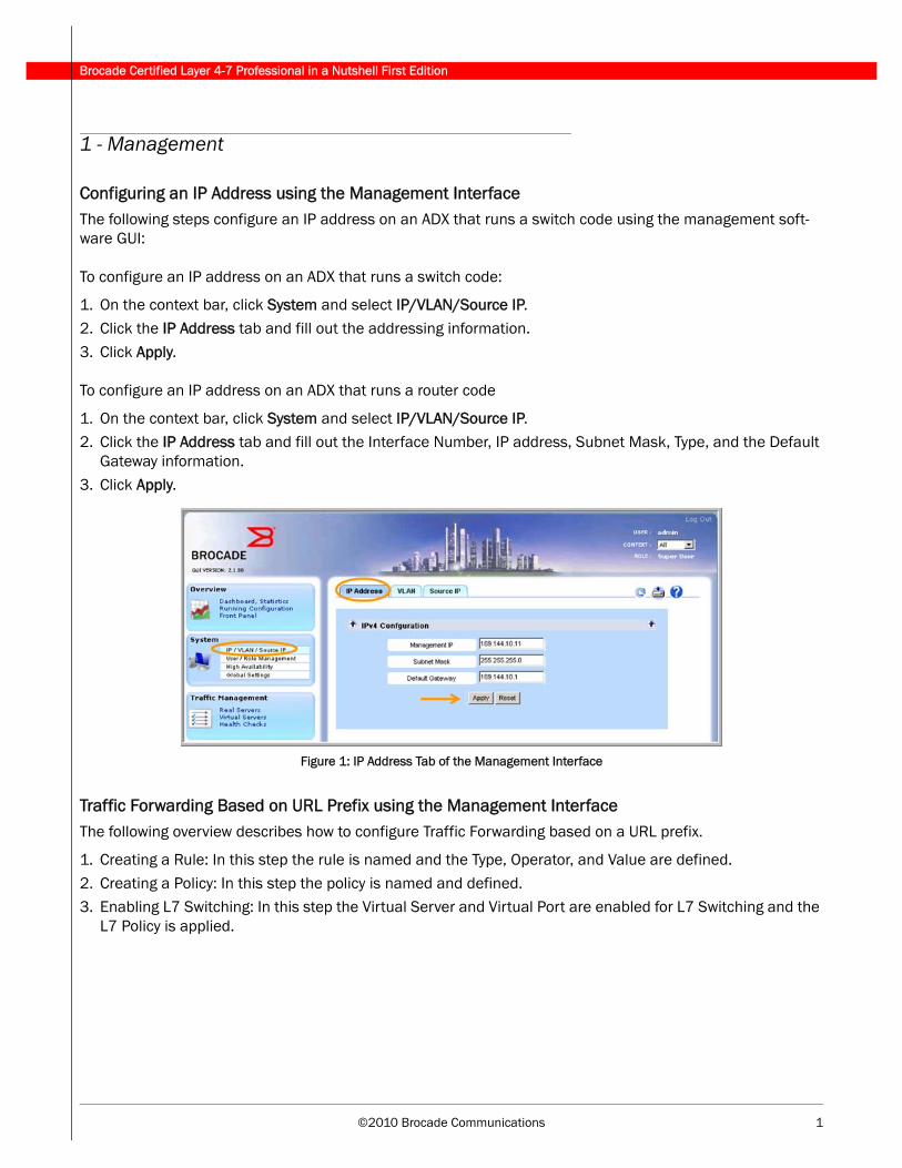
Configuring an IP Address using the Management InterfaceThe following steps configure an IP address on an ADX that runs a switch code using the management soft-ware GUI:
To configure an IP address on an ADX that runs a switch code:
1. On the context bar, click System and select IP/VLAN/Source IP.
2. Click the IP Address tab and fill out the addressing information.
3. Click Apply.
To configure an IP address on an ADX that runs a router code
1. On the context bar, click System and select IP/VLAN/Source IP.2. Click the IP Address tab and fill out the Interface Number, IP address, Subnet Mask, Type, and the Default
Gateway information.
3. Click Apply.
Figure 1: IP Address Tab of the Management Interface
Traffic Forwarding Based on URL Prefix using the Management InterfaceThe following overview describes how to configure Traffic Forwarding based on a URL prefix.
1. Creating a Rule: In this step the rule is named and the Type, Operator, and Value are defined.
2. Creating a Policy: In this step the policy is named and defined. 3. Enabling L7 Switching: In this step the Virtual Server and Virtual Port are enabled for L7 Switching and the
L7 Policy is applied.
Brocade Certified Layer 4-7 Professional in a Nutshell First Edition
2 ©2010 Brocade Communications
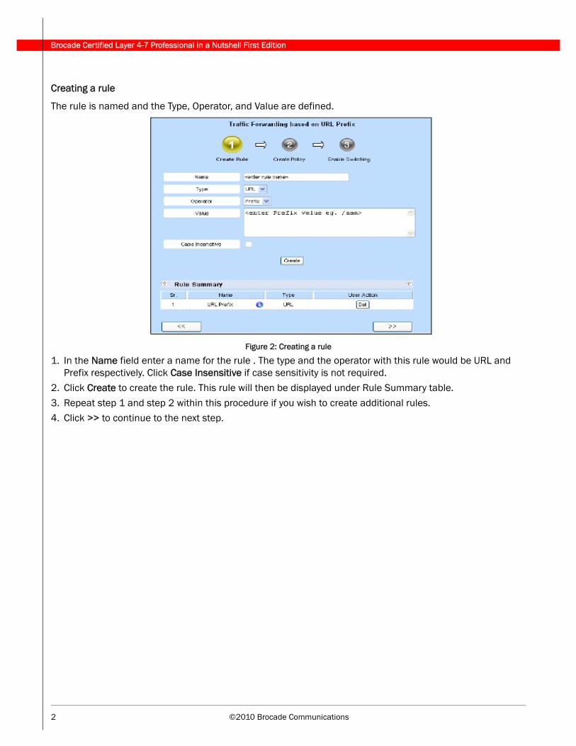
Creating a rule
The rule is named and the Type, Operator, and Value are defined.
Figure 2: Creating a rule
1. In the Name field enter a name for the rule . The type and the operator with this rule would be URL and Prefix respectively. Click Case Insensitive if case sensitivity is not required.
2. Click Create to create the rule. This rule will then be displayed under Rule Summary table.
3. Repeat step 1 and step 2 within this procedure if you wish to create additional rules.4. Click >> to continue to the next step.
©2010 Brocade Communications 3
Brocade Certified Layer 4-7 Professional in a Nutshell First Edition
Creating a policy
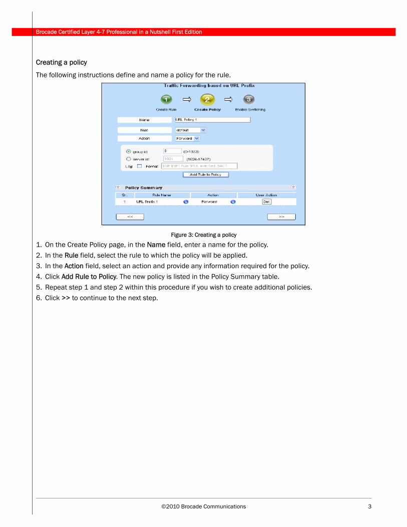
The following instructions define and name a policy for the rule.
Figure 3: Creating a policy
1. On the Create Policy page, in the Name field, enter a name for the policy.
2. In the Rule field, select the rule to which the policy will be applied.3. In the Action field, select an action and provide any information required for the policy.
4. Click Add Rule to Policy. The new policy is listed in the Policy Summary table.
5. Repeat step 1 and step 2 within this procedure if you wish to create additional policies.6. Click >> to continue to the next step.
Brocade Certified Layer 4-7 Professional in a Nutshell First Edition
4 ©2010 Brocade Communications
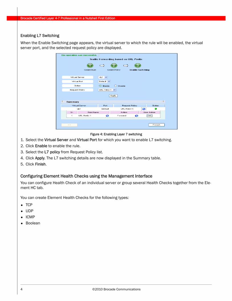
Enabling L7 Switching
When the Enable Switching page appears, the virtual server to which the rule will be enabled, the virtual server port, and the selected request policy are displayed.
Figure 4: Enabling Layer 7 switching
1. Select the Virtual Server and Virtual Port for which you want to enable L7 switching.
2. Click Enable to enable the rule.
3. Select the L7 policy from Request Policy list.4. Click Apply. The L7 switching details are now displayed in the Summary table.
5. Click Finish.
Configuring Element Health Checks using the Management InterfaceYou can configure Health Check of an individual server or group several Health Checks together from the Ele-ment HC tab.
You can create Element Health Checks for the following types:
• TCP
• UDP
• ICMP• Boolean
©2010 Brocade Communications 5
Brocade Certified Layer 4-7 Professional in a Nutshell First Edition
2 - Health Checks
Layer 3 Layer 3 Health Checks consist of ICMP-based IP pings and ARP requests. The ADX sends an ARP request and an IP ping to the real server to verify that the ADX can reach the server through the network. The ADX also sends an IP ping to a real server in the following circumstances:
• If the ARP entry for the server times out. In this case, the ADX uses the IP ping to create a new ARP entry for the server. The ARP request is sometimes referred to as a Layer 2 Health Check since the request is for the real server’s hardware layer address.
• If the time between the last packet sent to the server and the last packet received from the server increases. In this case, the ADX uses the IP ping to determine whether the slowed response time indicates loss of the server. If the server responds to the ping, the ADX then sends a Layer 4 or Layer 7 Health Check, depending on whether the port’s application type is known to the ADX. The ADX sends pings at an interval of 2 seconds apart, and retries unsuccessful pings up to 4 times by default. You can change the ping interval and retries if desired.
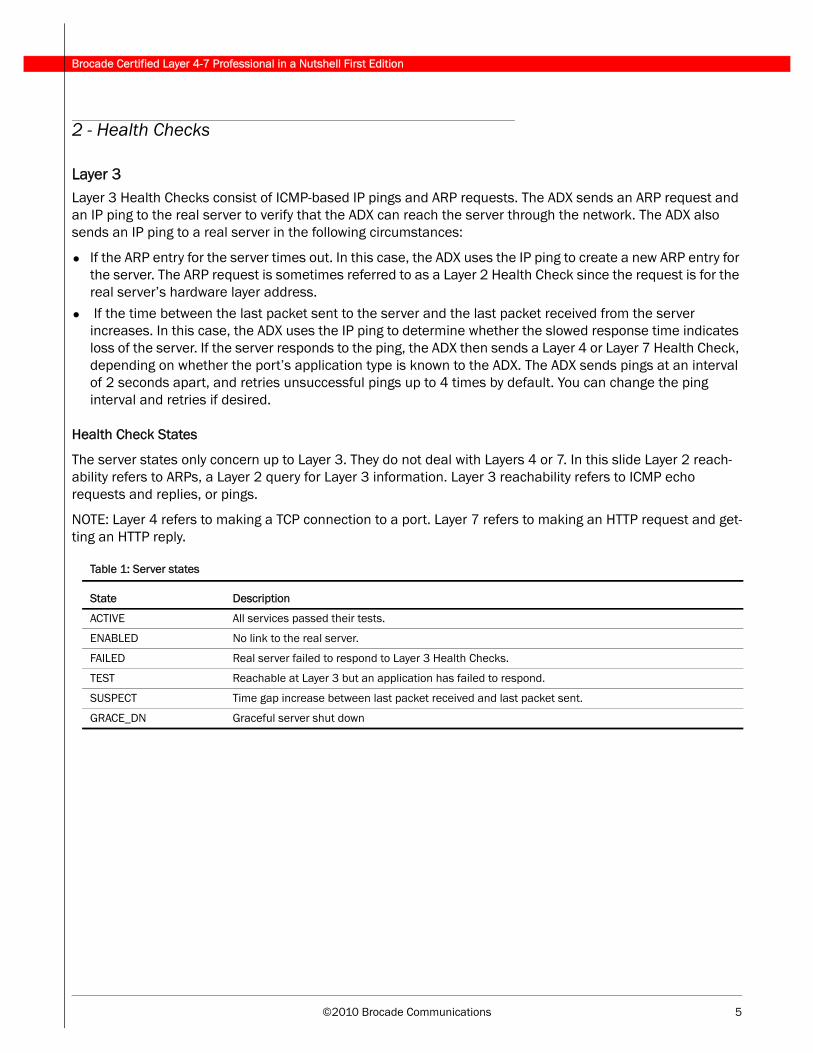
Health Check States
The server states only concern up to Layer 3. They do not deal with Layers 4 or 7. In this slide Layer 2 reach-ability refers to ARPs, a Layer 2 query for Layer 3 information. Layer 3 reachability refers to ICMP echo requests and replies, or pings.
NOTE: Layer 4 refers to making a TCP connection to a port. Layer 7 refers to making an HTTP request and get-ting an HTTP reply.
Table 1: Server states
State Description
ACTIVE All services passed their tests.
ENABLED No link to the real server.
FAILED Real server failed to respond to Layer 3 Health Checks.
TEST Reachable at Layer 3 but an application has failed to respond.
SUSPECT Time gap increase between last packet received and last packet sent.
GRACE_DN Graceful server shut down

Brocade Certified Layer 4-7 Professional in a Nutshell First Edition
6 ©2010 Brocade Communications
Layer 4 The Layer 4 Health Check can be a TCP or a UDP check.
TCP Health Check
When you bind a real server to a virtual server, the ADX performs either a Layer 4 TCP or UDP Health Check or a Layer 7 Health Check to bring up the application port that binds the real and virtual servers. If the applica-tion port is not one of the applications that is known to the ADX, the ADX uses a Layer 4 Health Check. Other-wise, the ADX uses the Layer 7 Health Check for the known application type.
TCP Health Check — The ADX checks the TCP port’s health based on a TCP three-way handshake:
• The ADX sends a TCP SYN packet to the port on the real server.
• The ADX expects the real server to respond with a SYN ACK.
• If the ADX receives the SYN ACK, the ADX sends a TCP RESET, satisfied that the TCP port is alive.
The default polling interval is 5 seconds and 3 retries, for busy servers increase interval or number of retries.
Figure 5: TCP Health Check
Table 2: Application states
State Description
ACTIVE Application has passed Health Check.
ENABLED No link to server.
FAILED Application has failed to respond to Layer 4 or 7 Health Check.
TEST Server is reachable at Layer 3 but application failed Layer 4 or 7 Health Check.
SUSPECT Time gap increase between last packet received and last packet sent.
GRACE_DN Graceful server shut down.
UNBND Application not bound to VIP graceful server shut down.
©2010 Brocade Communications 7
Brocade Certified Layer 4-7 Professional in a Nutshell First Edition
A Layer 4 Health Check to discover a new server involves the following:
• ARP for first Health Check.• Ping after successful ARP and when server behavior changes.
• TCP 3-way handshake during normal operation.
A Layer 4 Health check for an established server involves the following:
• ICMP to server.
• Monitor connections to server.• Enable keep alive to perform regular Layer 4 and Layer 7 Health Checks.
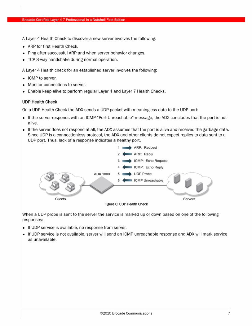
UDP Health Check
On a UDP Health Check the ADX sends a UDP packet with meaningless data to the UDP port:
• If the server responds with an ICMP “Port Unreachable” message, the ADX concludes that the port is not alive.
• If the server does not respond at all, the ADX assumes that the port is alive and received the garbage data. Since UDP is a connectionless protocol, the ADX and other clients do not expect replies to data sent to a UDP port. Thus, lack of a response indicates a healthy port.
Figure 6: UDP Health Check
When a UDP probe is sent to the server the service is marked up or down based on one of the following responses:
• If UDP service is available, no response from server.• If UDP service is not available, server will send an ICMP unreachable response and ADX will mark service
as unavailable.
Brocade Certified Layer 4-7 Professional in a Nutshell First Edition
8 ©2010 Brocade Communications
Layer 4 Customized Health Checks
A customized Health Check is only done when a there is a unique situation that cannot be accommodated by a simple Health Check.
Use customized Health Checks when one of the following is needed:
• A TCP SYN, SYN-ACK, ACK.
• On an uncommon port.
• Periodically without Layer 7 enabled.• On a server that is not bound.
• On multiple server states that may be combine in a Boolean condition.
Layer 7The ADX supports two kinds of HTTP Health Checks:
• HTTP status code (Basic): Health checks look at the status code returned in HTTP responses to keepalive requests.
• HTTP Content Verification (Custom): Health checks look at the actual HTML contained in HTTP responses to keepalive requests.
HTTP Status Code
The ADX sends HTTP HEAD or GET requests to cache servers when using Transparent Cache Switching (TCS) or HTTP servers when using Server Load Balancing (SLB). The HEAD or GET request specifies a page identi-fied by the Universal Resource Locator (URL) on the server. By default, the ADX sends a HEAD request for the default page, 1.0.
If the server responds with an acceptable status code, the ADX resets the connection and marks the port ACTIVE. For SLB, the default acceptable status codes for the check are 200–299 and 401. For TCS, the default acceptable status codes are 100–499.
If the server responds with a different status code, the ADX marks the HTTP port FAILED.
If the server does not respond, the ADX retries the Health Check up to the number of times configured (the default is two retries). If the server still does not respond, the ADX marks the server port FAILED and removes the server from the load-balancing rotation for HTTP service.
Note: You can change the status code range for individual servers. If you do so, the defaults are removed and only the status code ranges you specify cause the server to pass the Health Check.
©2010 Brocade Communications 9
Brocade Certified Layer 4-7 Professional in a Nutshell First Edition
HTTP Content Verification
The ADX sends HTTP HEAD or GET requests to cache servers (when using TCS) or HTTP servers (when using SLB). The HEAD or GET request specifies a page (identified by the URL) on the server. The ADX examines the page and compares the contents of the page to a list of user-defined selection criteria. Based on the results of this comparison, the ADX takes one of the following actions with respect to port 80 (HTTP) on the real server.
• If the page meets the criteria for keeping the port up, then the ADX marks the port ACTIVE. This means that the HTTP application has passed the Health Check.
• If the page meets the criteria for bringing the port down, then the ADX marks the port FAILED.• If the page meets none of the selection criteria, then the ADX marks the port either ACTIVE or FAILED
according to a user-defined setting.
Scripted Health ChecksIn a scripted Health Check, the ADX opens a connection to a port on a real server by sending an SYN packet. The ADX waits for the real server to send back a packet in response. The ADX looks in the response packet for a user-specified ASCII string, defined in a matching list on the ADX. The port on the real server is then marked ACTIVE or FAILED based on configuration settings in the matching list. For example, a matching list can be configured to mark a port ACTIVE or FAILED if the string is found, or mark the port ACTIVE or FAILED if the string is not found.
If no response is received within the configured interval (the default is five seconds), the ADX sends a RST and retries the Health Check. After the configured number of retries (the default is two retries), if the server still does not respond, the ADX marks the server port FAILED.
Scripted Health Checks uses the following process to mark a port:
• ADX opens a connection to a port (SYN)• Real server sends response
• ADX looks in the packet for a user-specified ASCII string
• Port on the real server marked ACTIVE or FAILED
Content verification for Unknown Ports
After a successful Layer 4 Health Check, the ADX waits for the real server to send back a packet in response ADX compares the contents of the ASCII string to a list of user-defined selection criteria in the matching list. Based on the results of this comparison, the ADX takes one of the following actions with respect to the port on the real server:
• If the text in the response meets the criteria for keeping the port up, then the ADX marks the port ACTIVE.
• If the text in the response meets the criteria for bringing the port down, then the ADX marks the port FAILED.
• If the text in the response meets none of the selection criteria, then the ADX marks the port either ACTIVE or FAILED according to a user-defined setting
• If no response is received within the configured interval (the default is five seconds), the ADX sends a RST and retries the Health Check. After the configured number of retries (the default is two retries), if the server still does not respond, the ADX marks the server port FAILED.

Brocade Certified Layer 4-7 Professional in a Nutshell First Edition
10 ©2010 Brocade Communications
Layer 7 Customized Health Check — Content Verification
You specify in the URL, what file (system.html) is needed to verify the Health Check and what method needs to be used (GET).
Figure 7: Layer 7 content verification
Example — A Scripted Health Check
In this example, the port http content-match m4 command binds matching list m4 to real server rs1. HTTP response messages coming from real server rs1 are examined using the selection criteria in matching list m4.
The port http url command sets the method used for HTTP keepalive requests and the URL of the page to be retrieved. This command is used in HTTP content verification Health Checks because the default method and URL page for HTTP keepalive requests are used in HTTP Health Checks,
The HEAD /1.1 method does not return an HTML file that the ADX can search and verify. Instead, specify the GET method, which does return an HTML file that can be examined using the matching list.
If only the http keep-alive is enabled, then the Layer7 Health Check is verifying a status code.
Example:
ADX(config)# server real-name rs1 192.168.1.1
ADX(config-rs-rs1)# port http content-match m4
ADX(config-rs-rs1)# port http url "GET /system.html"
ADX(config-rs-rs1)# exit
Example: Applications
• Checking the status of a database
• Health Check request to Web server• Web page request causes a database query
• Database responds to query
Web server formats response to Web page request and adds appropriate response codes.
©2010 Brocade Communications 11
Brocade Certified Layer 4-7 Professional in a Nutshell First Edition
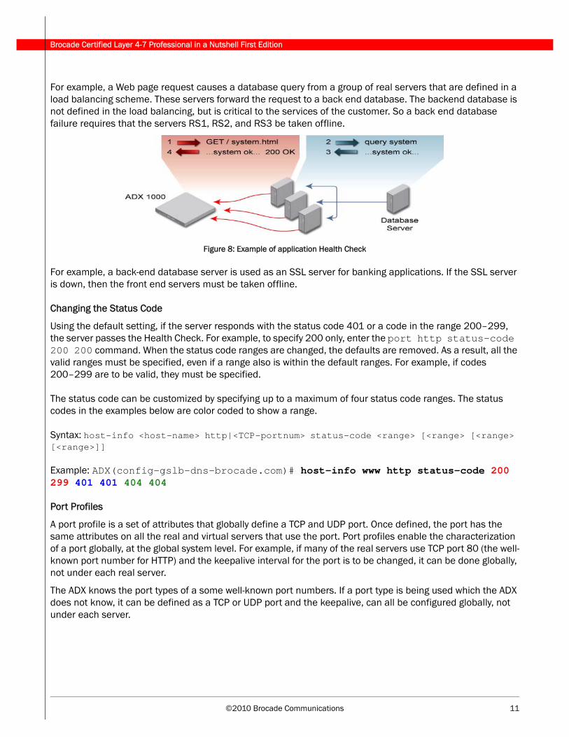
For example, a Web page request causes a database query from a group of real servers that are defined in a load balancing scheme. These servers forward the request to a back end database. The backend database is not defined in the load balancing, but is critical to the services of the customer. So a back end database failure requires that the servers RS1, RS2, and RS3 be taken offline.
Figure 8: Example of application Health Check
For example, a back-end database server is used as an SSL server for banking applications. If the SSL server is down, then the front end servers must be taken offline.
Changing the Status Code
Using the default setting, if the server responds with the status code 401 or a code in the range 200–299, the server passes the Health Check. For example, to specify 200 only, enter the port http status-code 200 200 command. When the status code ranges are changed, the defaults are removed. As a result, all the valid ranges must be specified, even if a range also is within the default ranges. For example, if codes 200–299 are to be valid, they must be specified.
The status code can be customized by specifying up to a maximum of four status code ranges. The status codes in the examples below are color coded to show a range.
Syntax: host-info <host-name> http|<TCP-portnum> status-code <range> [<range> [<range> [<range>]]
Example: ADX(config-gslb-dns-brocade.com)# host-info www http status-code 200 299 401 401 404 404
Port Profiles
A port profile is a set of attributes that globally define a TCP and UDP port. Once defined, the port has the same attributes on all the real and virtual servers that use the port. Port profiles enable the characterization of a port globally, at the global system level. For example, if many of the real servers use TCP port 80 (the well-known port number for HTTP) and the keepalive interval for the port is to be changed, it can be done globally, not under each real server.
The ADX knows the port types of a some well-known port numbers. If a port type is being used which the ADX does not know, it can be defined as a TCP or UDP port and the keepalive, can all be configured globally, not under each server.
Brocade Certified Layer 4-7 Professional in a Nutshell First Edition
12 ©2010 Brocade Communications
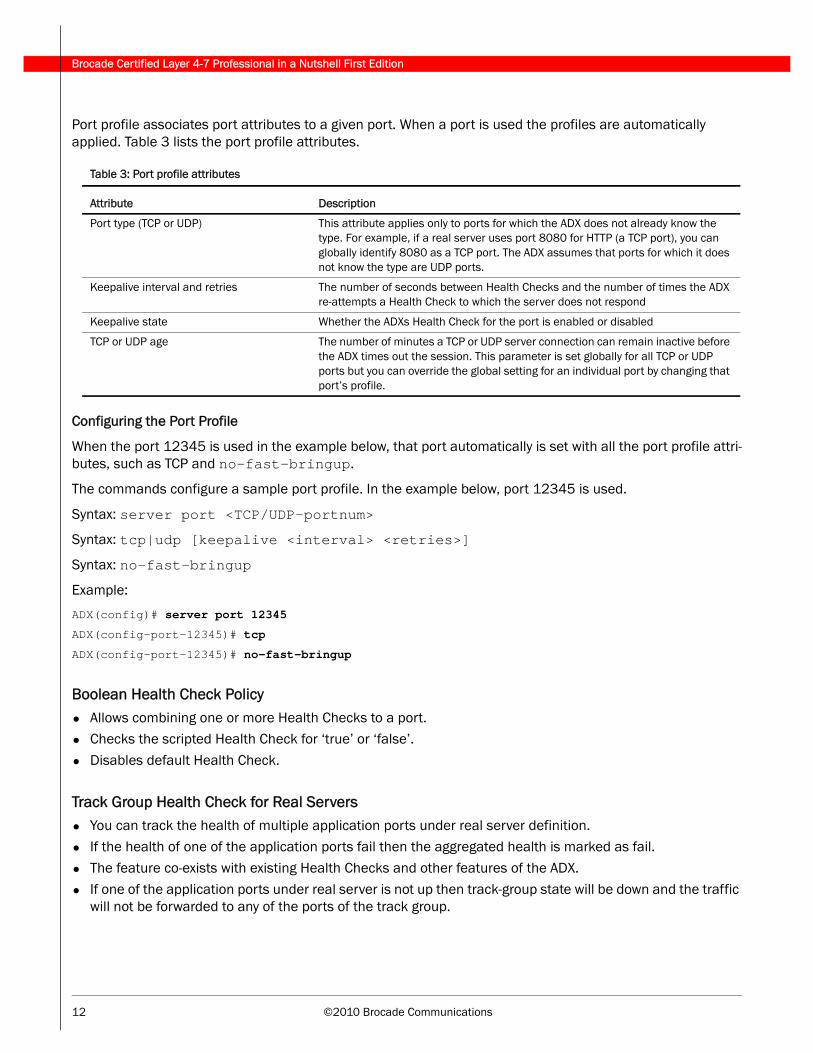
Port profile associates port attributes to a given port. When a port is used the profiles are automatically applied. Table 3 lists the port profile attributes.
Configuring the Port Profile
When the port 12345 is used in the example below, that port automatically is set with all the port profile attri-butes, such as TCP and no-fast-bringup.
The commands configure a sample port profile. In the example below, port 12345 is used.
Syntax: server port <TCP/UDP-portnum>
Syntax: tcp|udp [keepalive <interval> <retries>]
Syntax: no-fast-bringup
Example:
ADX(config)# server port 12345
ADX(config-port-12345)# tcp
ADX(config-port-12345)# no-fast-bringup
Boolean Health Check Policy• Allows combining one or more Health Checks to a port.• Checks the scripted Health Check for ‘true’ or ‘false’.
• Disables default Health Check.
Track Group Health Check for Real Servers• You can track the health of multiple application ports under real server definition.• If the health of one of the application ports fail then the aggregated health is marked as fail.
• The feature co-exists with existing Health Checks and other features of the ADX.
• If one of the application ports under real server is not up then track-group state will be down and the traffic will not be forwarded to any of the ports of the track group.
Table 3: Port profile attributes
Attribute Description
Port type (TCP or UDP) This attribute applies only to ports for which the ADX does not already know the type. For example, if a real server uses port 8080 for HTTP (a TCP port), you can globally identify 8080 as a TCP port. The ADX assumes that ports for which it does not know the type are UDP ports.
Keepalive interval and retries The number of seconds between Health Checks and the number of times the ADX re-attempts a Health Check to which the server does not respond
Keepalive state Whether the ADXs Health Check for the port is enabled or disabled
TCP or UDP age The number of minutes a TCP or UDP server connection can remain inactive before the ADX times out the session. This parameter is set globally for all TCP or UDP ports but you can override the global setting for an individual port by changing that port’s profile.
©2010 Brocade Communications 13
Brocade Certified Layer 4-7 Professional in a Nutshell First Edition
Track PortsIn a track port configuration, the tracking applies only to the primary port, which is the first port in the list of track ports.
If the client requests one of the other applications (one of the applications that is tracking the primary application) first, the ADX track feature does not apply.
You can configure sixteen track ports with priority for a VRRP-E instance.
Route Health Injection Considerations• ADX must be in same subnet as the router.• The same Layer 3 Switch port cannot be used for OSPF and for the globally-distributed SLB.
• Management station for the ADX must be on different subnet than the VIP whose health is being checked.
If advertisements of the network are not blocked, the switch will advertise a route to the network containing the Web site even if the Web site itself is unavailable.
After the ip dont-advertise command is entered, the switch advertises only a host route to the IP address. If the Web site fails the HTTP Health Check, the Layer 3 Switch removes the static host route for the Web site’s IP address and also does not advertise a network route for the network containing the IP address.
If the VIP and the management station are on the same subnet, the ip dont-advertise command will prevent the management station from reaching the ADX.
Route Health Injection ConfigurationThe following is an overview of Route Health Injection (RHI) configuration:
1. Enable a routing protocol (OSPF).
2. Configure an interface associated with the VIP.
3. Enable real servers and ports.4. Configure and bind VIP to real servers and enable VIP RHI.
Enabling the OSPF routing protocol across the network
The following example enables OSPF routing across the network.
Router-A(config)# router ospf
Router-A(config-ospf-router)# area 0
Router-A(config-ospf-router)# redistribution connected
Router-A(config-ospf-router)# int e4
Router-A(config-if-e100-4)# ip ospf area 0
Router-A(config-if-e100-4)# int e3
Router-A(config-if-e100-3)# ip ospf area 0
Brocade Certified Layer 4-7 Professional in a Nutshell First Edition
14 ©2010 Brocade Communications
Configuring the Route Health Injection (Health Check)
The following example configures a Health Check for RHI to use.
ADX_A(config)# healthck 10 tcp
ADX_A(config-hc-10)# dest-ip 10.10.10.201
ADX_A(config-hc-10)# host-route-ip 10.10.10.201
ADX_A(config-hc-10)# use-direct-connected-route
ADX_A(config-hc-10)# port http
ADX_A(config-hc-10)# protocol http
ADX_A(config-hc-10)# l4-check
ADX_A(config-hc-10)# exit
Configuring an interface associated with the VIP
The following example configures an interface associated with the VIP for RHI.
(config)# server virtual vip1 210.10.10.100
(config-vs-vip1)# port http
(config-vs-vip1)# bind http rs1 http
(config-vs-vip1)# advertise-vip-route
The advertise-vip-route command adds the VIP network to the ADX routing table. When used with OSPF redistribution static command, it allows the ADX to advertise the VIP route to OSPF neighbors.
(config-vs-vip1)# vip-route-subnet-mask-length 32
The vip-route-subnet-mask-length 32 command instructs the ADX to apply a 32-bit mask to the VIP route entry. This is also referred to as a host route.
Enabling real servers and ports
The following example enables the real servers and ports.
(config)# server source-nat
(config)# server real rs1 210.10.10.10
(config-rs-rs1)# port http
(config-rs-rs1)# port http keepalive
©2010 Brocade Communications 15
Brocade Certified Layer 4-7 Professional in a Nutshell First Edition
3 - Server Load Balancing (SLB)
Configure Virtual ServersAfter you define the actual application server’s physical addresses (real server), you then need to configure the following:
• The external application server address on the ADX. The external application server is the virtual server.
• It is the IP address or server name to which client browsers send requests.
(config)# server virtual-name VIP1 169.144.10.100
(config-vs-VIP1)# port ftp
(config-vs-VIP1)# bind ftp RS1 ftp RS2 ftp
(config-vs-VIP1)# server virtual VIP2 169.144.10.200
(config-vs-VIP2)# port http
(config-vs-VIP2)# bind http RS2 http RS3 http
When binding the virtual server to the real servers, there may be confusion on the bind statement. The bind statement is defined as follows:
bind <virtual server port> <real server name> <real server port>
Here is where the option of port translation comes into effect. The VIP could be configured with port number 4096. The bind statement is then used to provide the port translation:
bind 4096 rs2 http rs3 http
This provides some security for connections. You cannot access the http server unless your WEB browser is configured with 4096 as the proxy port number.
Enabling TCP/UDP Session LoggingWhen TCP/UDP session logging is enabled, the ADX sends a message to the external Syslog servers when the software creates a session table entry.
You can enable session logging globally for all ports or on an individual TCP or UDP port basis.
Globally enable logging for all new session table entries.
Syntax: [no] server connection-log all|src-nat [url] [cookie]
Example: ADX(config)# server connection-log all
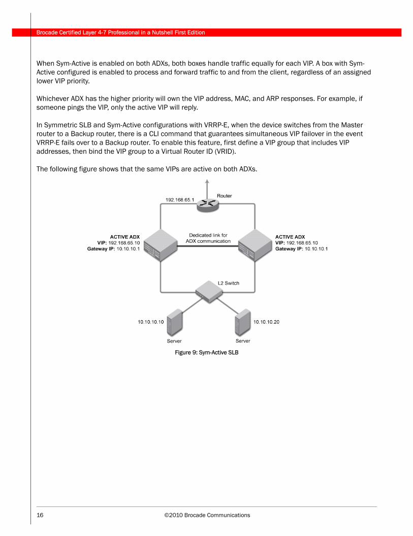
Sym-Active SLB (Active-Active)Sym-Active SLB is true active-active. Both ADXs handle traffic (active-active), and both ADXs are active for the same VIP. Sym-Active is configured on the VIP to enable the standby ADX to process traffic. The load and CPU processing per VIP is equally shared between both ADXs.
Brocade Certified Layer 4-7 Professional in a Nutshell First Edition
16 ©2010 Brocade Communications
When Sym-Active is enabled on both ADXs, both boxes handle traffic equally for each VIP. A box with Sym-Active configured is enabled to process and forward traffic to and from the client, regardless of an assigned lower VIP priority.
Whichever ADX has the higher priority will own the VIP address, MAC, and ARP responses. For example, if someone pings the VIP, only the active VIP will reply.
In Symmetric SLB and Sym-Active configurations with VRRP-E, when the device switches from the Master router to a Backup router, there is a CLI command that guarantees simultaneous VIP failover in the event VRRP-E fails over to a Backup router. To enable this feature, first define a VIP group that includes VIP addresses, then bind the VIP group to a Virtual Router ID (VRID).
The following figure shows that the same VIPs are active on both ADXs.
Figure 9: Sym-Active SLB
©2010 Brocade Communications 17
Brocade Certified Layer 4-7 Professional in a Nutshell First Edition
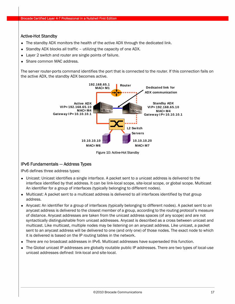
Active-Hot Standby• The standby ADX monitors the health of the active ADX through the dedicated link.
• Standby ADX blocks all traffic – utilizing the capacity of one ADX.• Layer 2 switch and router are single points of failure.
• Share common MAC address.
The server router-ports command identifies the port that is connected to the router. If this connection fails on the active ADX, the standby ADX becomes active.
Figure 10: Active-Hot Standby
IPv6 Fundamentals — Address TypesIPv6 defines three address types:
• Unicast: Unicast identifies a single interface. A packet sent to a unicast address is delivered to the interface identified by that address. It can be link-local scope, site-local scope, or global scope. Multicast An identifier for a group of interfaces (typically belonging to different nodes).
• Multicast: A packet sent to a multicast address is delivered to all interfaces identified by that group address.
• Anycast: An identifier for a group of interfaces (typically belonging to different nodes). A packet sent to an anycast address is delivered to the closest member of a group, according to the routing protocol’s measure of distance. Anycast addresses are taken from the unicast address spaces (of any scope) and are not syntactically distinguishable from unicast addresses. Anycast is described as a cross between unicast and multicast. Like multicast, multiple nodes may be listening on an anycast address. Like unicast, a packet sent to an anycast address will be delivered to one (and only one) of those nodes. The exact node to which it is delivered is based on the IP routing tables in the network.
• There are no broadcast addresses in IPv6. Multicast addresses have superseded this function.
• The Global unicast IP addresses are globally routable public IP addresses. There are two types of local-use unicast addresses defined: link-local and site-local.
Router
L2 Switch
Standby ADXVIP=192.168.65.10
MAC=M4Gateway IP=10.10.10.1
Active ADXVIP=192.168.65.10
MAC=M4Gateway IP=10.10.10.1
Servers
192.168.65.1MAC=M1
10.10.10.10MAC=M6
10.10.10.20MAC=M7
Dedicated link for ADX communication
Brocade Certified Layer 4-7 Professional in a Nutshell First Edition
18 ©2010 Brocade Communications
• Link-local address is for use on a single link and the site-local address is for use in a single site. A link-local address is required on each physical interface. Link-local addresses are designed to be used for addressing on a single link for purposes such as automatic address configuration, neighbor discovery, or in the absence of routers. It also may be used to communicate with other nodes on the same link. A link-local address is automatically assigned. Routers will not forward any packets with link-local source or destination addresses to other links.
• Site-local addresses are designed to be used for addressing inside of a site without the need for a global prefix. A site-local address cannot be reached from another site. A site-local address is not automatically assigned to a node. It must be assigned using automatic or manual configuration. Routers will not forward any packets with site-local source or destination addresses outside of the site.
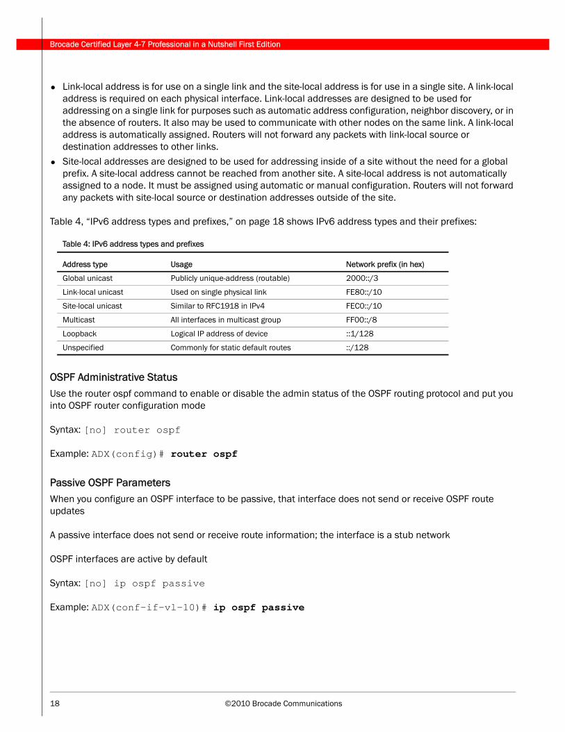
Table 4, “IPv6 address types and prefixes,” on page 18 shows IPv6 address types and their prefixes:
OSPF Administrative Status Use the router ospf command to enable or disable the admin status of the OSPF routing protocol and put you into OSPF router configuration mode
Syntax: [no] router ospf
Example: ADX(config)# router ospf
Passive OSPF ParametersWhen you configure an OSPF interface to be passive, that interface does not send or receive OSPF route updates
A passive interface does not send or receive route information; the interface is a stub network
OSPF interfaces are active by default
Syntax: [no] ip ospf passive
Example: ADX(conf-if-vl-10)# ip ospf passive
Table 4: IPv6 address types and prefixes
Address type Usage Network prefix (in hex)
Global unicast Publicly unique-address (routable) 2000::/3
Link-local unicast Used on single physical link FE80::/10
Site-local unicast Similar to RFC1918 in IPv4 FEC0::/10
Multicast All interfaces in multicast group FF00::/8
Loopback Logical IP address of device ::1/128
Unspecified Commonly for static default routes ::/128
©2010 Brocade Communications 19
Brocade Certified Layer 4-7 Professional in a Nutshell First Edition
Redistributing Routes into OSPFv3The redistribute command configures the redistribution of static IPv6 routes into OSPFv3, and uses route map “abc“ to control the routes that are redistributed.
You can specify the following route related aspects
• Default metric• Metric type
• Advertisement of an external aggregate route
HTTP RedirectThe HTTP redirect message instructs the client to redirect its HTTP connection directly to the remote server, bypassing the ADX
If all of the local real servers are unavailable and a remote server is available, the ADX sends an HTTP redirect message to the client. The HTTP redirect message instructs the client to redirect its HTTP connection directly to the remote server, bypassing the ADX.
ADX(config)# server real-name r1 10.0.1.5
ADX(config-rs-r1)# port http
ADX(config-rs-r1)# exit
ADX(config)# server real-name r2 10.0.2.200
ADX(config-rs-r2)# port http
ADX(config-rs-r2)# exit
ADX(config)# server remote-name r3 192.157.22.244
ADX(config-rs-r3)# source-nat
ADX(config-rs-r3)# port http
ADX(config-rs-r3)# exit
ADX(config)# server virtual-name-or-ip VIP 209.157.22.88
ADX(config-vs-VIP1)# port http
ADX(config-vs-VIP1)# bind http r1 80 r2 80 r3 80
ADX(config-vs-VIP1)# httpredirect
ADX(config-vs-VIP1)# exit
Brocade Certified Layer 4-7 Professional in a Nutshell First Edition
20 ©2010 Brocade Communications
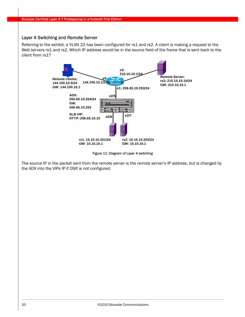
Layer 4 Switching and Remote ServerReferring to the exhibit, a VLAN 22 has been configured for rs1 and rs2. A client is making a request to the Web servers rs1 and rs2. Which IP address would be in the source field of the frame that is sent back to the client from rs1?
Figure 11: Diagram of Layer 4 switching
The source IP in the packet sent from the remote server is the remote server’s IP address, but is changed by the ADX into the VIPs IP if DSR is not configured.
Remote clients:144.100.10.5/24GW: 144.100.10.1
Remote Server: rs3: 210.10.10.10/24GW: 210.10.10.1
SLB VIP:HTTP: 206.65.10.10
e1: 206.65.10.253/24
rs2: 10.10.10.202/24GW: 10.10.10.1
ADX:206.65.10.254/24GW: 206.65.10.253
e3:210.10.10.1/24
e2/5
e2/7e2/6
rs1: 10.10.10.201/24GW: 10.10.10.1
e5:144.100.10.1/24 Router
©2010 Brocade Communications 21
Brocade Certified Layer 4-7 Professional in a Nutshell First Edition
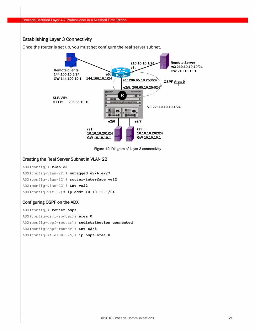
Establishing Layer 3 Connectivity
Once the router is set up, you must set configure the real server subnet.
Figure 12: Diagram of Layer 3 connectivity
Creating the Real Server Subnet in VLAN 22
ADX(config)# vlan 22
ADX(config-vlan-22)# untagged e2/6 e2/7
ADX(config-vlan-22)# router-interface ve22
ADX(config-vlan-22)# int ve22
ADX(config-vif-22)# ip addr 10.10.10.1/24
Configuring OSPF on the ADX
ADX(config)# router ospf
ADX(config-ospf-router)# area 0
ADX(config-ospf-router)# redistribution connected
ADX(config-ospf-router)# int e2/5
ADX(config-if-e100-2/5)# ip ospf area 0
Remote clients144.100.10.5/24GW 144.100.10.1
Remote Server rs3 210.10.10.10/24GW 210.10.10.1
SLB VIP:HTTP: 206.65.10.10
e1: 206.65.10.253/24
rs2:10.10.10.202/24GW 10.10.10.1
e2/5: 206.65.10.254/24
e2/7e2/6
rs1:10.10.10.201/24GW 10.10.10.1
e5: 144.100.10.1/24
Router
R
OSPF Area 0
VE 22: 10.10.10.1/24
210.10.10.1/24e3:
Brocade Certified Layer 4-7 Professional in a Nutshell First Edition
22 ©2010 Brocade Communications
Remote Real ServersFor basic real server configuration, you need to specify a name and the real server’s IP address, then add the application ports that you want to load balance.
When you define a real server, you specify whether the real server is local or remote:
• Local: Connected to the ADX at Layer 2; the ADX uses local servers for regular load balancing• Remote: Connected to the ADX through one or more router hops; the ADX uses remote servers only if all the
local servers are unavailable
To configure the real servers, enter the following commands:
ADX(config)# server real R1 10.10.10.10
ADX(config-rs-R1)# port http
ADX(config-rs-R1)# exit
ADX(config)# server real R2 10.10.10.20
ADX(config-rs-R2)# port http
ADX(config-rs-R2)# exit
ADX(config)# server real R3 10.10.10.30
ADX(config-rs-R3)# backup
ADX(config-rs-R3)# port http
ADX(config-rs-R3)# exit
ADX(config)# server remote-name R4 198.10.10.40
ADX(config-rs-R4)# port http
ADX(config-rs-R4)# exit
ADX(config)# server remote-name R5 198.10.10.50
ADX(config-rs-R5)# backup
ADX(config-rs-R5)# port http
Notice that the backup command is used with servers R3 and R5.
Web Hosting the ADX and Real Servers in Different SubnetsThe ADX requires only one IP address to use for management access to the device. When the ADX and real servers are on different subnets, one of the following must be configured:
• Multiple subnets configured on the router.
• Source NAT enabled and source IP addresses (up to eight) configured on the ADX.
©2010 Brocade Communications 23
Brocade Certified Layer 4-7 Professional in a Nutshell First Edition
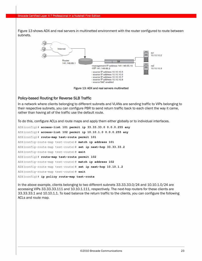
Figure 13 shows ADX and real servers in multinetted environment with the router configured to route between subnets.
Figure 13: ADX and real servers multinetted
Policy-based Routing for Reverse SLB TrafficIn a network where clients belonging to different subnets and VLANs are sending traffic to VIPs belonging to their respective subnets, you can configure PBR to send return traffic back to each client the way it came, rather than having all of the traffic use the default route.
To do this, configure ACLs and route maps and apply them either globally or to individual interfaces.
ADX(config)# access-list 101 permit ip 33.33.33.0 0.0.0.255 any
ADX(config)# access-list 102 permit ip 10.10.1.0 0.0.0.255 any
ADX(config)# route-map test-route permit 101
ADX(config-route-map test-route)# match ip address 101
ADX(config-route-map test-route)# set ip next-hop 33.33.33.2
ADX(config-route-map test-route)# exit
ADX(config)# route-map test-route permit 102
ADX(config-route-map test-route)# match ip address 102
ADX(config-route-map test-route)# set ip next-hop 10.10.1.2
ADX(config-route-map test-route)# exit
ADX(config)# ip policy route-map test-route
In the above example, clients belonging to two different subnets 33.33.33.0/24 and 10.10.1.0/24 are accessing VIPs 33.33.33.111 and 10.10.1.111, respectively. The next-hop routers for these clients are 33.33.33.1 and 10.10.1.1. To load balance the return traffic to the clients, you can configure the following ACLs and route map.
Brocade Certified Layer 4-7 Professional in a Nutshell First Edition
24 ©2010 Brocade Communications
Best Path to a Remote ServerIf you want to eliminate unnecessary hops, enable the ADX to learn the MAC address from which the remote server’s Health Check reply is received, and send subsequent Health Checks directly through that MAC address.
This command does not apply to local servers as local servers are attached at Layer 2, the ADX does not need to use a gateway or otherwise route the Health Check to the server.
Syntax: [no] use-learned-mac-address
Example: ADX(config-rs-remote1)# use-learned-mac-address
Policy-based SLBWhen policy-based SLB is enabled for a port on a virtual server, the ADX examines the source IP address of each new connection sent to the VIP on the port. The ADX looks up the source IP address of the request in an internal policy list. The policy list is a table that associates IP addresses with real server groups. If an entry for the IP address is found in the policy list, then the ADX forwards the request to the associated real server group. If no entry for the IP address is found, the ADX directs the request to a server group specified as the "default" server group.
Policy-based SLBs have the following characteristics:
• Policy-based SLB is enabled for individual ports on virtual servers.
• Since policy-based SLB is enabled on a per-VIP basis, some VIPs configured on the ADX can have policy-based SLB enabled, while others do not.
• Policy-based SLB can exist on a standalone device or in high-availability configurations.
• Policy-based SLB can co-exist with other ADX features, including FWLB, NAT, and TCS.
• Policy-based SLB cannot co-exist on the same VIP with Layer 7 switching features, including URL switching and cookie switching.
Configuring Real Server with SNMP Query RequirementsTo configure real servers with SNMP query requirements you need to do the following:
1. Establish SNMP community strings. SNMP versions 1 and 2c use community strings to restrict SNMP access. By default, you cannot perform any SNMP Set operations since a read-write community string is not configured.
2. A list of the SNMP Object ID (OID) must be configured under a real server. An OID represents the weight of the real server, for example server CPU utilization or its memory usage.
©2010 Brocade Communications 25
Brocade Certified Layer 4-7 Professional in a Nutshell First Edition
Assigning Weights to Real ServersWhen configuring Weights on a Real Server, consider the following:
• Real Server Weight assignments apply to all ports configured under the real server.• For the Weighted Round Robin predictor, server weights are assigned at the server level and not the server
port level. The load balancing however is based on per-server port.
• The Weighted Round Robin predictor has VIP port-level granularity. This is reflected in the output from the show server session and show server conn commands since they display output for the Weighted Round Robin predictor at a per vip-port level.
Syntax: [no] weight <weight-value>
Example:
ADX(config)# server real rsA
ADX(config-rs-rsA)# weight 1
ADX(config-rs-rsA)# exit
ADX(config)# server real rsB
ADX(config-rs-rsB)# weight 2
ADX(config-rs-rsB)# exit
ADX(config)# server real rsC
ADX(config-rs-rsC)# weight 3
ADX(config-rs-rsC)# exit
Configuring VIP Failover in VRRP-E with Symmetric SLB and Sym-ActiveGuarantees simultaneous VIP failover in the event VRRP-E fails over to a backup router. To enable this feature, first define a VIP group that includes VIP addresses, then bind the VIP group to a Virtual Router ID (VRID).
Define a VIP group:
ADX(config)# server vip-group 1
ADX(config-vip-group-[1])# vip 10.10.1.100
ADX(config-vip-group-[1])# exit
Bind the VIP group to a VRID:
ADX(config)# router vrrp -extended
ADX(config)# interface e 1/2
ADX(config-if-e100-1/2)# ip vrrp vrid 1
ADX(config-if-e100-12-vrid-1)# vip-group 1
Brocade Certified Layer 4-7 Professional in a Nutshell First Edition
26 ©2010 Brocade Communications
Virtual Router ID (VRID)A VRID has the following characteristics:
• A VRID consists of one master router and one or more backup routers.• The master router is the router that owns the IP addresses you associate with the VRID.
• The master router is sometimes called the “owner”.
• Configure the VRID on the router that owns the default gateway interface.• The other router in the VRID does not own the IP addresses associated with the VRID, but provides the
backup path if the master router becomes unavailable.
High AvailabilityIn high availability configurations, with Brocade hardware-based SSL acceleration in either SSL Termination or SSL Proxy mode, synchronization of terminated or proxied SSL sessions is not supported.
Stateful and Stateless Server Load BalancingStateful load balancing:
• Uses session table entries to track connections between the client and server, and requires the server responses to pass back through the ADX.
• The ADX uses the session table entries for Health Checks, stateful failover in hot-standby configurations, and other functions.
Stateless load balancing:
• Does not create session table entries and does not require the server response to pass back through the ADX.
• Typically used by applications that are not context sensitive.
Examples for Using Stateless Server Load Balancing
For example, the ADX and real servers can be connected through a network that provides multiple return paths to the client. Since the port is stateless, the ADX does not assume that the application is unhealthy if the server’s response does not flow back through the ADX.
For example, if the server farm provides non-secure Web content in addition to secured transaction processing using SSL, the ADX can be used to maintain state information for the SSL connections while allowing the HTTP (Web) connections to be stateless. The SSL connections flow back through the ADX but the HTTP connections use any available path as determined by a real server’s gateway and other routers back to the client.
©2010 Brocade Communications 27
Brocade Certified Layer 4-7 Professional in a Nutshell First Edition
Real Server Selection for a Stateless PortThe following are characteristics of real server selection for a stateless port:
• ADX does not use the standard SLB load-balancing methods when selecting a real server for a stateless application port.
• Hash values are used to select a real server.
• For UDP connections consisting of one client packet and one server response packet, disable the stateless SLB hashing algorithm.
• DNS is an example of a UDP port.
• The advantage of disabling the stateless SLB hashing algorithm is that a new real server can be selected immediately after it is brought up.
• When hashing is disabled, the ADX uses the round-robin load balancing method to select a real server for each request.
Configuring a Stateless Application PortTo configure an application port to be stateless, enable the stateless parameter on the port in the virtual server. Here is an example:
ADX(config)# server real R1 10.10.10.1
ADX(config-rs-R1)# port http
ADX(config-rs-R1)# exit
ADX(config)# server real R2 10.10.11.1
ADX(config-rs-R2)# port http
ADX(config-rs-R2)# exit
ADX(config)#server virtual-name-or-ip StatelessHTTP 192.168.4.69
ADX(config-vs-StatelessHTTP)# port http stateless
ADX(config-vs-StatelessHTTP)# bind http R1 http
ADX(config-vs-StatelessHTTP)# bind http R2 http
Syntax: [no] port <tcp/udp-portnum> stateless
The <tcp/udp-portnum> parameter specifies the application port you want to make stateless.
Brocade Certified Layer 4-7 Professional in a Nutshell First Edition
28 ©2010 Brocade Communications
4 - Content Switching (CSW)
Layer 7 CSW: Three Step ConfigurationTo configure content switch, define the content switching rules and policies. A rule specifies the content that the ADX looks for in the incoming traffic, and a policy associates rules with one or more actions that specify how the ADX handles traffic matching the rule.
1. Define a CSW rule.2. Create a policy. Policies “match rules” and take action.
3. Bind policy to a virtual server.
Example: CSW Rules and Policies
Global PolicyThe following example creates a policy named Policy1.
SLB(config)# csw-policy "Policy1"
Rules
• url pattern: matches a string in the URL header• header: matches a string in the header
The following example redirects the client to SSL to www.brocade.com.
SLB(config-csw-Policy1)# default redirect “brocade.com" "*" ssl
NOTE: In this example, the wildcard ( * ) is used to match all URLs.
HTTP URL RewriteThe following are HTTP URL rewrite characteristics:
• Allows the ADX to insert, delete, and replace URL content at any offset in a HTTP request.• Only Forward and Persists are typically used for HTTP URL Rewrite actions on HTTP requests, because the
other actions do not pass requests to servers.
• Seamlessly integrates with Content Switching (CSW).• HTTP URL Rewrite can be configured as a dependent action for primary CSW actions.
• You can define multiple dependent CSW actions that will work together with a primary CSW action.
• Dependent CSW actions include log, client-ip insertion, header insertion, cookie insertion, and deletion.
©2010 Brocade Communications 29
Brocade Certified Layer 4-7 Professional in a Nutshell First Edition
HTTP Rewrite on Server ResponseThe following are HTTP rewrite on server response characteristics:
• Required in an SSL-Offload environment when the real-servers sends redirect messages to incoming clients.
• Modifies responses such as replacing "http://" with https://.
• Can be applied selectively based on response code and the embedded URL.• Can be configured to modify any other part of the HTTP-header in any other response code.
• You can configure HTTP URL rewrite and CSW on HTTP, SSL, or any unknown port.
• HTTP URL rewrite supports HTTP 1.1 keepalive and TCP Offload.• You define HTTP URL rewrite actions under a CSW policy.
• Before you define an HTTP URL rewrite action, you must define a primary CSW action.
• For each matched CSW rule, you can only define one primary action.• Dependent CSW actions include HTTP URL Rewrite, log, and others such as client-ip insertion, header
insertion, cookie insertion, and deletion.
• HTTP URL rewrite cannot be configured as a default action.
Configuring HTTP Server Response RewriteThe following instructions configure an HTTP server response rewrite:
1. Create a CSW rule using the csw-rule r2 url exists command to specify the response codes to be acted upon.
2. Create a CSW rule using the csw-rule <rule-name> response-body pattern <pattern to be found> command to specify the URLs to be modified.
3. Create a CSW-Policy using the csw-policy <policy-name> type response-rewrite command.
4. Bind CSW-Policy to the virtual-server port using the port http server-response-rewrite-policy <policy-name> command.
5. (Optional) Specify content-type using the response-rewrite content-type <type-string> command to enable this feature.
Example:
ADX(config)# csw-rule r2 url exists
ADX(config)# csw-rule r21 response-body pattern http://www.abc.com/
csw-policy "p22" type response-rewrite
match "r2" response-body-rewrite
match "r21" rewrite response-body-replace "https://www.abc.com/" offset 0 length 19
ADX(config)# server virtual-name-or-ip v1 100.1.1.10
ADX(config-vs-v1)# port ssl response-rewrite-policy "p22“
ADX(config)# csw-policy p1 type response-rewrite
ADX(config-vs)# response-rewrite content-type "application/javascript"
Brocade Certified Layer 4-7 Professional in a Nutshell First Edition
30 ©2010 Brocade Communications
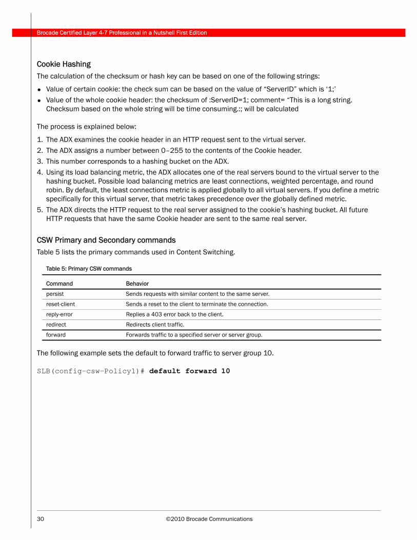
Cookie HashingThe calculation of the checksum or hash key can be based on one of the following strings:
• Value of certain cookie: the check sum can be based on the value of “ServerID” which is ‘1;’• Value of the whole cookie header: the checksum of :ServerID=1; comment= “This is a long string.
Checksum based on the whole string will be time consuming.:; will be calculated
The process is explained below:
1. The ADX examines the cookie header in an HTTP request sent to the virtual server.
2. The ADX assigns a number between 0–255 to the contents of the Cookie header.3. This number corresponds to a hashing bucket on the ADX.
4. Using its load balancing metric, the ADX allocates one of the real servers bound to the virtual server to the hashing bucket. Possible load balancing metrics are least connections, weighted percentage, and round robin. By default, the least connections metric is applied globally to all virtual servers. If you define a metric specifically for this virtual server, that metric takes precedence over the globally defined metric.
5. The ADX directs the HTTP request to the real server assigned to the cookie’s hashing bucket. All future HTTP requests that have the same Cookie header are sent to the same real server.
CSW Primary and Secondary commandsTable 5 lists the primary commands used in Content Switching.
The following example sets the default to forward traffic to server group 10.
SLB(config-csw-Policy1)# default forward 10
Table 5: Primary CSW commands
Command Behavior
persist Sends requests with similar content to the same server.
reset-client Sends a reset to the client to terminate the connection.
reply-error Replies a 403 error back to the client.
redirect Redirects client traffic.
forward Forwards traffic to a specified server or server group.
©2010 Brocade Communications 31
Brocade Certified Layer 4-7 Professional in a Nutshell First Edition
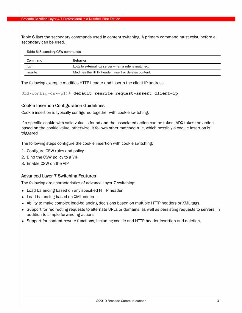
Table 6 lists the secondary commands used in content switching. A primary command must exist, before a secondary can be used.
The following example modifies HTTP header and inserts the client IP address:
SLB(config-csw-p1)# default rewrite request-insert client-ip
Cookie Insertion Configuration GuidelinesCookie insertion is typically configured together with cookie switching.
If a specific cookie with valid value is found and the associated action can be taken, ADX takes the action based on the cookie value; otherwise, it follows other matched rule, which possibly a cookie insertion is triggered
The following steps configure the cookie insertion with cookie switching:
1. Configure CSW rules and policy
2. Bind the CSW policy to a VIP
3. Enable CSW on the VIP
Advanced Layer 7 Switching FeaturesThe following are characteristics of advance Layer 7 switching:
• Load balancing based on any specified HTTP header.
• Load balancing based on XML content.• Ability to make complex load-balancing decisions based on multiple HTTP headers or XML tags.
• Support for redirecting requests to alternate URLs or domains, as well as persisting requests to servers, in addition to simple forwarding actions.
• Support for content-rewrite functions, including cookie and HTTP header insertion and deletion.
Table 6: Secondary CSW commands
Command Behavior
log Logs to external log server when a rule is matched.
rewrite Modifies the HTTP header, insert or deletes content.
Brocade Certified Layer 4-7 Professional in a Nutshell First Edition
32 ©2010 Brocade Communications
5 - Global Server Load Balancing (GSLB)
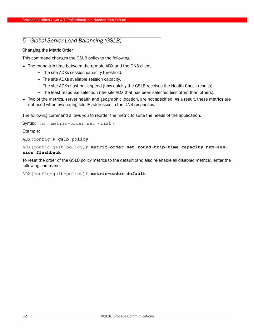
Changing the Metric Order
This command changes the GSLB policy to the following:
• The round-trip-time between the remote ADX and the DNS client.
- The site ADXs session capacity threshold.
- The site ADXs available session capacity.- The site ADXs flashback speed (how quickly the GSLB receives the Health Check results).
- The least response selection (the site ADX that has been selected less often than others).
• Two of the metrics, server health and geographic location, are not specified. As a result, these metrics are not used when evaluating site IP addresses in the DNS responses.
The following command allows you to reorder the metric to suite the needs of the application.
Syntax: [no] metric-order set <list>
Example:
ADX(config)# gslb policy
ADX(config-gslb-policy)# metric-order set round-trip-time capacity num-ses-sion flashback
To reset the order of the GSLB policy metrics to the default (and also re-enable all disabled metrics), enter the following command:
ADX(config-gslb-policy)# metric-order default
©2010 Brocade Communications 33
Brocade Certified Layer 4-7 Professional in a Nutshell First Edition
The show gslb policy CommandThe default settings can be displayed by using the show gslb default command.
The example below displays the GSLB metric policy. The settings have been changed from the default, the geographic location has been set to be the first selection and session capacity threshold as the second and the available session capacity as the third.
ADX(config)# show gslb policy
Default metric order: DISABLE
Metric processing order:
1-Round trip time between remote SI and client
2-Remote SI's session capacity threshold
3-Remote SI's available session capacity
4-Server flashback speed
5-Least response selection
DNS active-only: DISABLE DNS best-only: DISABLE DNS override: DISABLE
DNS cache-proxy: DISABLE DNS transparent-intercept: DISABLE
DNS cname-detect: DISABLE Modify DNS response TTL: ENABLE
DNS TTL: 10 (sec), DNS check interval: 30 (sec)
Remote SI status update period: 30 (sec)
Session capacity threshold: 90% Session availability tolerance: 10%
Round trip time tolerance: 10%, round trip time explore percentage: 5%
Round trip time cache prefix: 20, round trip time cache interval: 120 (sec)
Flashback appl-level delay tolerance: 10%, TCP-level delay tolerance: 10%
Connection load: DISABLE
AffinityThe GSLB affinity feature configures the GSLB ADX to always prefer a specific site ADX for queries from clients whose addresses are within a given IP prefix.
This feature is useful in the following situations:
• Using a primary site for all queries and use other sites only as backups.• Using a site located near clients within a private network for all queries from the private network.
Modifying GSLB Parameters Related to DNS ResponsesBy default, the ADX does not remove an IP address from a DNS reply even if the address fails a Health Check.
To configure the ADX to remove IP addresses from DNS replies when those addresses fail a Health check, enter the following commands:
ADX(config)# gslb policy
ADX(config-gslb-policy)# dns active-only
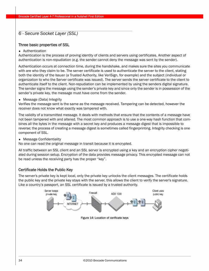
Brocade Certified Layer 4-7 Professional in a Nutshell First Edition
34 ©2010 Brocade Communications
6 - Secure Socket Layer (SSL)
Three basic properties of SSL• Authentication Authentication is the process of proving identity of clients and servers using certificates. Another aspect of authentication is non-repudiation (e.g. the sender cannot deny the message was sent by the sender).
Authentication occurs at connection time, during the handshake, and makes sure the sites you communicate with are who they claim to be. The server certificate is used to authenticate the server to the client, stating both the identity of the Issuer (a Trusted Authority, like VeriSign, for example) and the subject (individual or organization to who the Server certificate was issued). The server sends the server certificate to the client to authenticate itself to the client. Non-repudiation can be implemented by using the senders digital signature. The sender signs the message using the sender’s private key and since only the sender is in possession of the sender’s private key, the message must have come from the sender.
• Message (Data) IntegrityVerifies the message sent is the same as the message received. Tampering can be detected, however the receiver does not know what exactly was tampered with.
The validity of a transmitted message. It deals with methods that ensure that the contents of a message have not been tampered with and altered. The most common approach is to use a one-way hash function that com-bines all the bytes in the message with a secret key and produces a message digest that is impossible to reverse; the process of creating a message digest is sometimes called fingerprinting. Integrity checking is one component of SSL.
• Message ConfidentialityNo one can read the original message in transit because it is encrypted.
All traffic between an SSL client and an SSL server is encrypted using a key and an encryption cipher negoti-ated during session setup. Encryption of the data provides message privacy. This encrypted message can not be read unless the receiving party has the proper “key”.
Certificate Holds the Public KeyThe server's private key is kept local, only the private key unlocks the client messages. The certificate holds the public key and the private key stays with the server, this allows the client to verify the server's signature. Like a country’s passport, an SSL certificate is issued by a trusted authority.
Figure 14: Location of cerificate keys
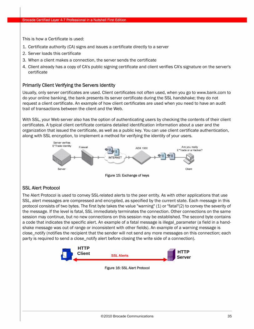
©2010 Brocade Communications 35
Brocade Certified Layer 4-7 Professional in a Nutshell First Edition
This is how a Certificate is used:
1. Certificate authority (CA) signs and issues a certificate directly to a server2. Server loads this certificate
3. When a client makes a connection, the server sends the certificate
4. Client already has a copy of CA's public signing certificate and client verifies CA's signature on the server's certificate
Primarily Client Verifying the Servers IdentityUsually, only server certificates are used. Client certificates not often used, when you go to www.bank.com to do your online banking, the bank presents its server certificate during the SSL handshake; they do not request a client certificate. An example of how client certificates are used when you need to have an audit trail of transactions between the client and the Web.
With SSL, your Web server also has the option of authenticating users by checking the contents of their client certificates. A typical client certificate contains detailed identification information about a user and the organization that issued the certificate, as well as a public key. You can use client certificate authentication, along with SSL encryption, to implement a method for verifying the identity of your users.
Figure 15: Exchange of keys
SSL Alert Protocol The Alert Protocol is used to convey SSL-related alerts to the peer entity. As with other applications that use SSL, alert messages are compressed and encrypted, as specified by the current state. Each message in this protocol consists of two bytes. The first byte takes the value "warning" (1) or "fatal"(2) to convey the severity of the message. If the level is fatal, SSL immediately terminates the connection. Other connections on the same session may continue, but no new connections on this session may be established. The second byte contains a code that indicates the specific alert. An example of a fatal message is illegal_parameter (a field in a hand-shake message was out of range or inconsistent with other fields). An example of a warning message is close_notify (notifies the recipient that the sender will not send any more messages on this connection; each party is required to send a close_notify alert before closing the write side of a connection).
Figure 16: SSL Alert Protocol
HTTP Server
HTTP Client SSL Alerts

Brocade Certified Layer 4-7 Professional in a Nutshell First Edition
36 ©2010 Brocade Communications
SSL Handshake ProtocolThe SSL Handshake Protocol allows the server and client to authenticate to each other and to negotiate a cipher suite and cryptographic keys to be used to protect data sent in an SSL record. It is used before any application data is transmitted. And it consists of a series of messages exchanged between the client and the server.
Figure 17: SSL handshake
SSL Protocol Stack
The cryptographic parameters of the session state are produced by the SSL Handshake Protocol, which oper-ates on top of the SSL Record Layer. When an SSL client and server first start communicating, they agree on a protocol version, select cryptographic algorithms, optionally authenticate each other, and use public-key encryption techniques to generate shared secrets. These processes are performed in the handshake protocol, which can be summarized as follows:
• The client sends a client hello message to which the server must respond with a server hello message, or else a fatal error will occur and the session will fail. The client hello and server hello are used to establish security enhancement capabilities between client and server.
• Following the client hello messages, the server will send its certificate, if it is to be authenticated. This is normally the case. Additionally, a server key exchange message may be sent, if it is required. Now the server will send the server hello done message, indicating that the hello-message phase of the handshake is complete. The server will then wait for a client response.
©2010 Brocade Communications 37
Brocade Certified Layer 4-7 Professional in a Nutshell First Edition
• If the server has sent a certificate request message, the client must send either the certificate message or a no certificate alert. The client key exchange message is now sent, and the content of that message will depend on the public key algorithm selected between the client hello and the server hello. The client sends the finished message under the new algorithms, keys, and secrets.
• In response, the server will send its own change cipher spec message, transfer the pending to the current Cipher Spec, and send its Finished message under the new Cipher Spec. At this point, the handshake is complete and the client and server may begin to exchange application layer data.
(This text is an extract from the SSL 3.0 Specification.)
Note: The SSL "handshake" is a key concept in this protocol. The idea of the handshake is not to exchange the actual data but the metadata that allows for connections to be set up.
Self-signed CertificatesBy default, the ADX does not accept certificates that have been issued by a CA that is not trusted. An ADX only accepts certificates which have been signed by a CA that is configured under the SSL profile. For testing pur-poses, you may want to use self-signed certificates (generated using the Open SSL utilities or by the ADX cert gen utility) on the SSL client.
The following example configures a ADX to accept self signed certificates:
Syntax: [no] allow-self-signed-cert
ADX(config)# ssl profile profile1
ADX(config-ssl-profile-profile1)# allow-self-signed-cert
Option 1: SSL Termination ModeIn SSL Termination mode, the ADX performs the following:
• Terminates the SSL connections. • Decrypts the data.
• Sends clear text to the server.
The ADX offloads the encryption and decryption services from the server CPU and performs them in hardware, thereby offloading the burden from the server. The ADX maintains an encrypted data-channel with the client and a clear-text data channel with the server.
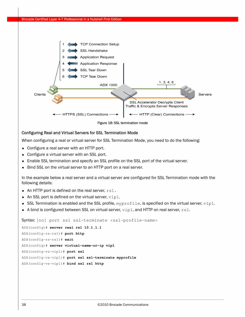
Brocade Certified Layer 4-7 Professional in a Nutshell First Edition
38 ©2010 Brocade Communications
Figure 18: SSL termination mode
Configuring Real and Virtual Servers for SSL Termination Mode
When configuring a real or virtual server for SSL Termination Mode, you need to do the following:
• Configure a real server with an HTTP port.• Configure a virtual server with an SSL port.
• Enable SSL termination and specify an SSL profile on the SSL port of the virtual server.
• Bind SSL on the virtual server to an HTTP port on a real server.
In the example below a real server and a virtual server are configured for SSL Termination mode with the following details:
• An HTTP port is defined on the real server, rs1.• An SSL port is defined on the virtual server, vip1.
• SSL Termination is enabled and the SSL profile, myprofile, is specified on the virtual server, vip1.
• A bind is configured between SSL on virtual server, vip1, and HTTP on real server, rs1.
Syntax: [no] port ssl ssl-terminate <ssl-profile-name>
ADX(config)# server real rs1 10.1.1.1
ADX(config-rs-rs1)# port http
ADX(config-rs-rs1)# exit
ADX(config)# server virtual-name-or-ip vip1
ADX(config-vs-vip1)# port ssl
ADX(config-vs-vip1)# port ssl ssl-terminate myprofile
ADX(config-vs-vip1)# bind ssl rs1 http
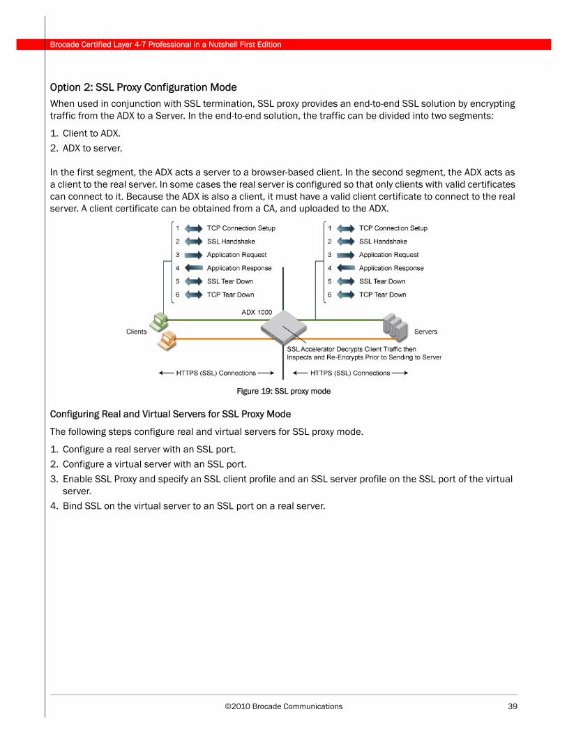
©2010 Brocade Communications 39
Brocade Certified Layer 4-7 Professional in a Nutshell First Edition
Option 2: SSL Proxy Configuration ModeWhen used in conjunction with SSL termination, SSL proxy provides an end-to-end SSL solution by encrypting traffic from the ADX to a Server. In the end-to-end solution, the traffic can be divided into two segments:
1. Client to ADX.
2. ADX to server.
In the first segment, the ADX acts a server to a browser-based client. In the second segment, the ADX acts as a client to the real server. In some cases the real server is configured so that only clients with valid certificates can connect to it. Because the ADX is also a client, it must have a valid client certificate to connect to the real server. A client certificate can be obtained from a CA, and uploaded to the ADX.
Figure 19: SSL proxy mode
Configuring Real and Virtual Servers for SSL Proxy Mode
The following steps configure real and virtual servers for SSL proxy mode.
1. Configure a real server with an SSL port.2. Configure a virtual server with an SSL port.
3. Enable SSL Proxy and specify an SSL client profile and an SSL server profile on the SSL port of the virtual server.
4. Bind SSL on the virtual server to an SSL port on a real server.
Brocade Certified Layer 4-7 Professional in a Nutshell First Edition
40 ©2010 Brocade Communications
In the example below a real server and a virtual server are configured for SSL Proxy mode with the following details:
• An SSL port is defined on the real server rs2.
• An SSL port is defined on the virtual server vip2.
• SSL Proxy is configured and the SSL client profile, clientprofile, and SSL server profile, serverprofile, are specified on the virtual server, vip1.
• A bind is configured between SSL on virtual server vip2 and SSL on the real server rs2.
Syntax: [no] port ssl ssl-proxy <ssl-profile-name-1> <ssl-profile-name-2>
ADX(config)# server real rs2 10.1.1.1
ADX(config-rs-rs2)# port ssl
ADX(config-rs-rs2)# exit
ADX(config)# server virtual-name-or-ip vip2
ADX(config-vs-vip2)# port ssl
ADX(config-vs-vip2)# port ssl ssl-proxy clientprofile serverprofile
ADX(config-vs-vip2)# bind ssl rs2 ssl
SSL Session ID SwitchingSSL session ID switching allows the ADX to connect a client to the same real server to which it had previously established an SSL connection. It is a security parameter set by SSLHP (SSL Handshake Protocol) and has a variable length value contained in the session_id field in SSLHP messages. If the value in the session_id field that the client sends to the server is non-zero, the ADX can connect the client to the server that originally sent the session_id value. SSL session ID switching is supported for SSL v3.0 and higher only.
Creating a TCP ProfileYou can disable the following TCP features within a TCP profile:
• Nagle’s algorithm.• The delayed ACK algorithm.
• All outgoing data packets except the last one from a tcp-transmit queue.
You can disable Nagle’s algorithm within a TCP profile as shown in the following example:
ADX(config)# tcp profile tcpprofile1
ADX(config-tcp-profile-tcpprofile1)# nagle off
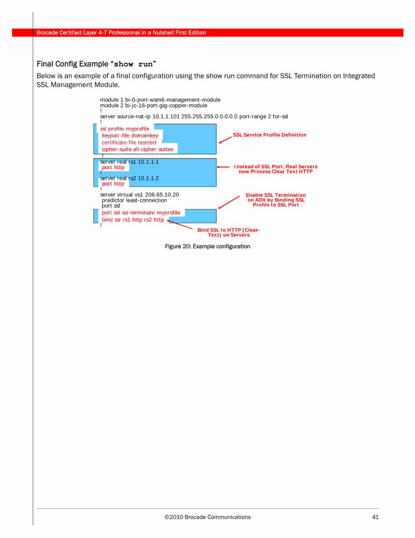
©2010 Brocade Communications 41
Brocade Certified Layer 4-7 Professional in a Nutshell First Edition
Final Config Example “show run”Below is an example of a final configuration using the show run command for SSL Termination on Integrated SSL Management Module.
Figure 20: Example configuration
module 1 bi-0-port-wsm6-management-modulemodule 2 bi-jc-16-port-gig-copper-module!server source-nat-ip 10.1.1.101 255.255.255.0 0.0.0.0 port-range 2 for-ssl!ssl profile myprofilekeypair-file domainkeycertificate-file testcertcipher-suite all-cipher-suites!server real rs1 10.1.1.1port http!server real rs2 10.1.1.2port http!server virtual vs1 206.65.10.20predictor least-connectionport sslport ssl ssl-terminate myprofilebind ssl rs1 http rs2 http!
SSL Service Profile Definition
Enable SSL Termination on ADX by Binding SSL
Profile to SSL Port
Bind SSL to HTTP (Clear-Text) on Servers
Instead of SSL Port, Real Servers now Process Clear Text HTTP
Brocade Certified Layer 4-7 Professional in a Nutshell First Edition
42 ©2010 Brocade Communications
7 - Security
Secure Access ManagementYou can use standard ACLs to control the following access methods to management functions on an ADX:
• Telnet access
• SSH access
• Web management access• SNMP access
Configuring authentication-method lists for RADIUSBy default, a user enters User EXEC mode after a successful login through Telnet or SSH. Optionally, you can configure the device so that a user enters Privileged EXEC mode after a Telnet or SSH login. The user’s privi-lege level is based on the privilege level granted during login. This places the user directly into the specified mode so that the user does not have to enter their password multiple times to gain access.
Syntax: aaa authentication login privilege-mode
Examples of authentication-method lists
To configure an authentication-method list for the Privileged EXEC and CONFIG levels of the CLI, enter the fol-lowing command.
ADX(config)# aaa authentication enable default local
This command configures the device to use the local user accounts to authenticate attempts to access the Privileged EXEC and CONFIG levels of the CLI.
The following is an example of how to configure the device to consult a RADIUS server first to authenticate attempts to access the Privileged EXEC and CONFIG levels of the CLI, then consult the local user accounts if the RADIUS server is unavailable, enter the following command.
ADX(config)# aaa authentication enable default radius local
Syntax: [no] aaa authentication snmp-server|web-server|enable|login default <method1> [<method2>] [<method3>] [<method4>] [<method5>] [<method6>] [<method7>]
The snmp-server|web-server|enable|login parameter specifies the type of access this authenti-cation-method list controls. You can configure one authentication-method list for each type of access.
©2010 Brocade Communications 43
Brocade Certified Layer 4-7 Professional in a Nutshell First Edition
DoS Protection — Configuring a Security FilterFor each rule, you can configure whatever action needs to be taken if an attack occurs. The ADX can log the attack and drop the attacking packet.
Syntax: security filter <filter-name>
Syntax: rule rule-name <drop> <log>
Apart from regular rules there is also a generic rule. A generic rule needs to be defined before it can be bound. to a filter.
The example below uses a generic rule to filter a packet that matches all the criteria configured that would satisfy the rule description. So, a TCP packet with source-ip greater than 10.10.1.101 and TCP destination port greater than 20 and with string "400" at the 3rd byte offset from l4-data will get dropped. The configured generic rule will have to be bound to a filter to take effect.
ADX(config)# security generic gen1
ADX(config-sec-gen-gen1)# ip-source gteq ip 10.10.1.101
ADX(config-sec-gen-gen1)# tcp-dest gt val 20
ADX(config-sec-gen-gen1)# l4-data 3 eq str "400“
ADX(config)# security filter filter1
ADX(config-sec-filter1)# rule generic gen1 drop
Brocade Certified Layer 4-7 Professional in a Nutshell First Edition
44 ©2010 Brocade Communications
8 - Techniques Used in Troubleshooting
Prioritizing Management TrafficFacilitates uninterrupted access of traffic destined to the management IP address, even under heavy load conditions. This feature allows you to prioritize management traffic based on the following:
• Client IP address and subnet
• Protocol (TCP/UDP/IP)• TCP or UDP port number
Syntax: server prioritize-mgmt-traffic <source ip> <mask> <destination ip> [<protocol>] [<port>]
Example: ADX(config)# server prioritize-mgmt-traffic 1.1.1.1 255.255.255.0 10.45.16.104 6 80
Transaction Rate LimitingThe ip tcp|udp|icmp trans-rate monitor-interval <interval> conn-rate <rate> hold-down-time <minutes> command configures the ADX to monitor incoming TCP traffic.
The monitor-interval <interval> specifies the amount of time used to measure incoming traffic. This parameter is specified in increments of 100ms. For example, to measure traffic over a 1 second interval, you would specify 10 for this parameter.
The conn-rate <rate> specifies a threshold for the number of bytes per second from any one IP address. Traffic exceeding this rate over the specified interval is subject to hold down.
The hold-down-time <minutes> specifies the number of minutes that traffic from an IP address that has sent packets at rate higher than the configured threshold is to be held down.
The ip tcp|udp trans-rate <ports> command applies Transaction Rate Limiting to either TCP or UDP traffic coming into specified ports. The <ports> parameter specifies one or more TCP or UDP ports to monitor. Up to 4 ports can be monitored.
Syntax: ip tcp|udp|icmp trans-rate monitor-interval <interval> conn-rate <rate> hold-down-time <minutes>
Syntax: ip tcp|udp trans-rate <ports>
The following example states that if any more than 100 TCP packets per second come from the same IP address over a 1 minute interval, then all TCP traffic from that IP address is held down for 5 minutes. Then Transaction Rate Limiting is applied to TCP traffic coming into port 80 on interface 1/1.
ADX(config)# ip tcp trans-rate monitor-interval 600 conn-rate 100 hold-down-time 5
ADX(config)# interface ethernet 1/1
ADX(config-if-1/1)# ip tcp trans-rate 80
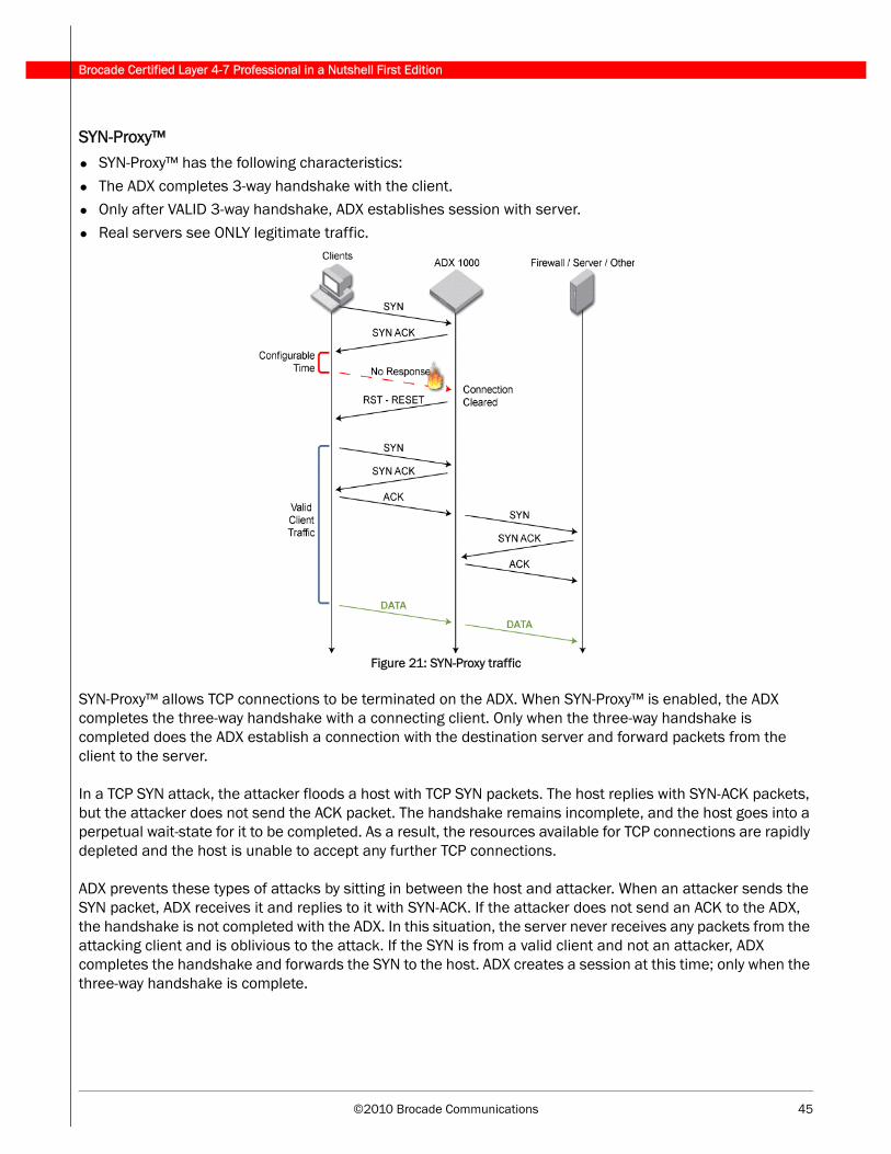
©2010 Brocade Communications 45
Brocade Certified Layer 4-7 Professional in a Nutshell First Edition
SYN-Proxy™• SYN-Proxy™ has the following characteristics:
• The ADX completes 3-way handshake with the client.• Only after VALID 3-way handshake, ADX establishes session with server.
• Real servers see ONLY legitimate traffic.
Figure 21: SYN-Proxy traffic
SYN-Proxy™ allows TCP connections to be terminated on the ADX. When SYN-Proxy™ is enabled, the ADX completes the three-way handshake with a connecting client. Only when the three-way handshake is completed does the ADX establish a connection with the destination server and forward packets from the client to the server.
In a TCP SYN attack, the attacker floods a host with TCP SYN packets. The host replies with SYN-ACK packets, but the attacker does not send the ACK packet. The handshake remains incomplete, and the host goes into a perpetual wait-state for it to be completed. As a result, the resources available for TCP connections are rapidly depleted and the host is unable to accept any further TCP connections.
ADX prevents these types of attacks by sitting in between the host and attacker. When an attacker sends the SYN packet, ADX receives it and replies to it with SYN-ACK. If the attacker does not send an ACK to the ADX, the handshake is not completed with the ADX. In this situation, the server never receives any packets from the attacking client and is oblivious to the attack. If the SYN is from a valid client and not an attacker, ADX completes the handshake and forwards the SYN to the host. ADX creates a session at this time; only when the three-way handshake is complete.
Brocade Certified Layer 4-7 Professional in a Nutshell First Edition
46 ©2010 Brocade Communications
Port FlappingThe following are port characteristics of port flapping:
• Port comes up as active and then flips to failed.• Port marked as active then it passed Layer 4 Health Check.
• Port marked as failed then it did not pass Layer 7 Health Check.
• The server no-fast-bringup command delays the marking of a port.
If the Layer 7 Health Check fails, it is still possible for the Layer 4 Health Check to be successful. Since the Layer 4 Health Check runs before the Layer 7 Health Check, upon completion of a successful Layer 4 Health Check the ADX will mark the server as ‘Active’. The ADX will then run the Layer 7 Health Check and when it fails, the server will be marked as ‘Failed’. The ADX will continue to run the Health Checks, Layer 4 and then Layer 7, and the port will be seen as flapping.
To prevent the flapping, use the server no-fast-bringup command. This command delays the marking of the port as active until all the Health Checks are completed.
Transparent VIPsUse this feature when you want to configure multiple ADXs to load balance the same VIP.
To enable a transparent VIP, enable the feature globally, then configure a cache redirection policy and apply it locally to the ADX ports connected to the clients. The cache redirection policy identifies the application ports on the VIP that you want to load balance.
To configure an individual virtual server for the transparent VIP feature, enter the following command:
Syntax: [no] transparent-vip
Example: ADX(config-vs-TransVIP)# transparent-vip
Packet FiltersOne or more filter IDs must be created in order to store the packets in the capture buffer. A filter ID consists of a set of filters that specify the attributes of the packets to be stored in the capture buffer, up to 16 filter IDs can be configured. Once this limit is reached, the specify command will fail.
Within a filter ID, filters can be specified for Layer 1–4 information or for a pattern within a packet.
By default a filter ID is configured to match any packet. Within a filter ID, all the filters must match a received packet in order for the packet to be captured.
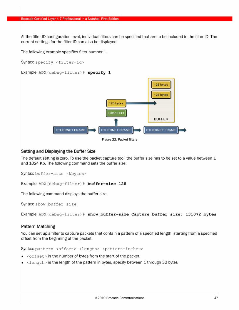
©2010 Brocade Communications 47
Brocade Certified Layer 4-7 Professional in a Nutshell First Edition
At the filter ID configuration level, individual filters can be specified that are to be included in the filter ID. The current settings for the filter ID can also be displayed.
The following example specifies filter number 1.
Syntax: specify <filter-id>
Example: ADX(debug-filter)# specify 1
Figure 22: Packet filters
Setting and Displaying the Buffer SizeThe default setting is zero. To use the packet capture tool, the buffer size has to be set to a value between 1 and 1024 Kb. The following command sets the buffer size:
Syntax: buffer-size <kbytes>
Example: ADX(debug-filter)# buffer-size 128
The following command displays the buffer size:
Syntax: show buffer-size
Example: ADX(debug-filter)# show buffer-size Capture buffer size: 131072 bytes
Pattern MatchingYou can set up a filter to capture packets that contain a pattern of a specified length, starting from a specified offset from the beginning of the packet.
Syntax: pattern <offset> <length> <pattern-in-hex>
• <offset> is the number of bytes from the start of the packet• <length> is the length of the pattern in bytes, specify between 1 through 32 bytes
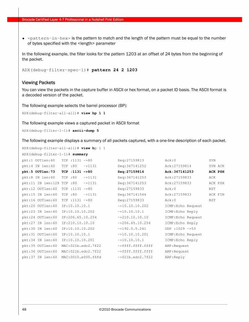
Brocade Certified Layer 4-7 Professional in a Nutshell First Edition
48 ©2010 Brocade Communications
• <pattern-in-hex> is the pattern to match and the length of the pattern must be equal to the number of bytes specified with the <length> parameter
In the following example, the filter looks for the pattern 1203 at an offset of 24 bytes from the beginning of the packet.
ADX(debug-filter-spec-1)# pattern 24 2 1203
Viewing PacketsYou can view the packets in the capture buffer in ASCII or hex format, on a packet ID basis. The ASCII format is a decoded version of the packet.
The following example selects the barrel processor (BP):
ADX(debug-filter-all-all)# view bp 1 1
The following example views a captured packet in ASCII format
ADX(debug-filter-1-1)# ascii-dump 5
The following example displays a summary of all packets captured, with a one-line description of each packet.
ADX(debug-filter-all-all)# view bp 1 1
ADX(debug-filter-1-1)# summary
pkt:1 OUTlen:60 TCP :1131 ->80 Seq:27159813 Ack:0 SYN
pkt:4 IN len:60 TCP :80 ->1131 Seq:367141252 Ack:27159814 SYN ACK
pkt:5 OUTlen:73 TCP :1131 ->80 Seq:27159814 Ack:367141253 ACK PSH
pkt:8 IN len:60 TCP :80 ->1131 Seq:367141253 Ack:27159833 ACK
pkt:11 IN len:128 TCP :80 ->1131 Seq:367141253 Ack:27159833 ACK PSH
pkt:12 OUTlen:60 TCP :1131 ->80 Seq:27159833 Ack:0 RST
pkt:15 IN len:60 TCP :80 ->1131 Seq:367141544 Ack:27159833 ACK FIN
pkt:16 OUTlen:60 TCP :1131 ->80 Seq:27159833 Ack:0 RST
pkt:20 OUTlen:60 IP:10.10.10.1 ->10.10.10.202 ICMP:Echo Request
pkt:23 IN len:60 IP:10.10.10.202 ->10.10.10.1 ICMP:Echo Reply
pkt:24 OUTlen:60 IP:206.65.10.254 ->210.10.10.10 ICMP:Echo Request
pkt:27 IN len:60 IP:210.10.10.10 ->206.65.10.254 ICMP:Echo Reply
pkt:30 IN len:60 IP:10.10.10.202 ->192.5.5.241 UDP :1029 ->53
pkt:31 OUTlen:60 IP:10.10.10.1 ->10.10.10.201 ICMP:Echo Request
pkt:34 IN len:60 IP:10.10.10.201 ->10.10.10.1 ICMP:Echo Reply
pkt:35 OUTlen:60 MAC:021b.edc2.7f22 ->ffff.ffff.ffff ARP:Request
pkt:36 OUTlen:60 MAC:021b.edc2.7f22 ->ffff.ffff.ffff ARP:Request
pkt:37 IN len:60 MAC:0010.e000.f6fd ->021b.edc2.7f22 ARP:Reply
©2010 Brocade Communications 49
Brocade Certified Layer 4-7 Professional in a Nutshell First Edition
Chained Certificate VerificationWhen the server certificate is not signed directly by the root CA, but signed by an intermediate CA, there are two possible scenarios:
• The client has the intermediate CAs Certificate.
- There are NO additional requirements. When the server sends a certificate that is signed by the intermediate CA, the client browser will be able to process it successfully.
• Client does NOT have the intermediate CAs certificate
- The server sends a certificate that is signed by intermediate CA. Since the end-client has no knowl-edge of the intermediate CA, it denies the certificate and the process is unsuccessful.
To resolve this issue, the server must send its own certificate and the intermediate CAs certificate that is signed the root CA.
ADX Supported Key FormatThe ADX accepts server certificates in the following formats:
• ADX supports keys in PEM (Privacy Enhanced Mail) or PKCS12 (Public Key Cryptography Standard 12) formats
• Public Key Cryptography Standard 12 (PKCS12)
You can convert between PFX and one of the two formats using OpenSSL on a Windows machine.
Associate SSL Profile to Key Pair and Certificate 1. Associate the RSA key pair to the SSL profile using the keypair-file <key-file> command.
- Example: ADX(config-ssl-profile-myprofile)# keypair-file domainkey
2. Associate the certificate with the SSL profile using the certificate-file <cert-file> command.
- Example: ADX(config-ssl-profile-myprofile)# certificate-file testcert3. Verify that you associate the correct RSA key with its associated certificate.
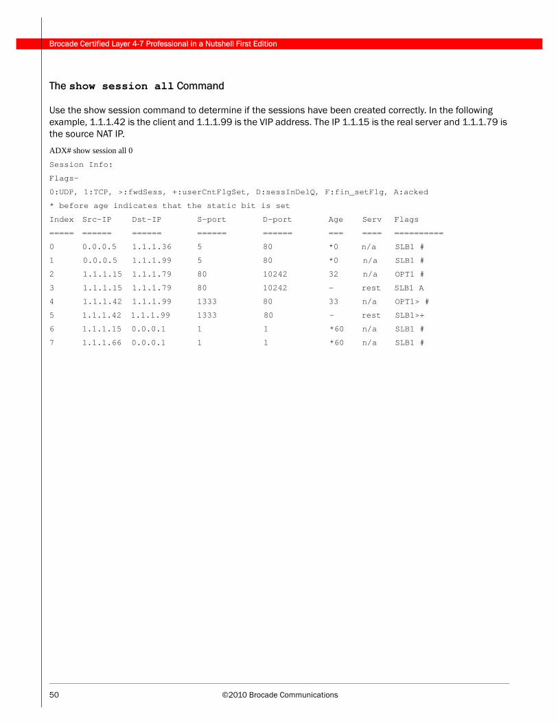
Brocade Certified Layer 4-7 Professional in a Nutshell First Edition
50 ©2010 Brocade Communications
The show session all Command
Use the show session command to determine if the sessions have been created correctly. In the following example, 1.1.1.42 is the client and 1.1.1.99 is the VIP address. The IP 1.1.15 is the real server and 1.1.1.79 is the source NAT IP.
ADX# show session all 0
Session Info:
Flags-
0:UDP, 1:TCP, >:fwdSess, +:userCntFlgSet, D:sessInDelQ, F:fin_setFlg, A:acked
* before age indicates that the static bit is set
Index Src-IP Dst-IP S-port D-port Age Serv Flags
===== ====== ====== ====== ====== === ==== ==========
0 0.0.0.5 1.1.1.36 5 80 *0 n/a SLB1 #
1 0.0.0.5 1.1.1.99 5 80 *0 n/a SLB1 #
2 1.1.1.15 1.1.1.79 80 10242 32 n/a OPT1 #
3 1.1.1.15 1.1.1.79 80 10242 - rest SLB1 A
4 1.1.1.42 1.1.1.99 1333 80 33 n/a OPT1> #
5 1.1.1.42 1.1.1.99 1333 80 - rest SLB1>+
6 1.1.1.15 0.0.0.1 1 1 *60 n/a SLB1 #
7 1.1.1.66 0.0.0.1 1 1 *60 n/a SLB1 #
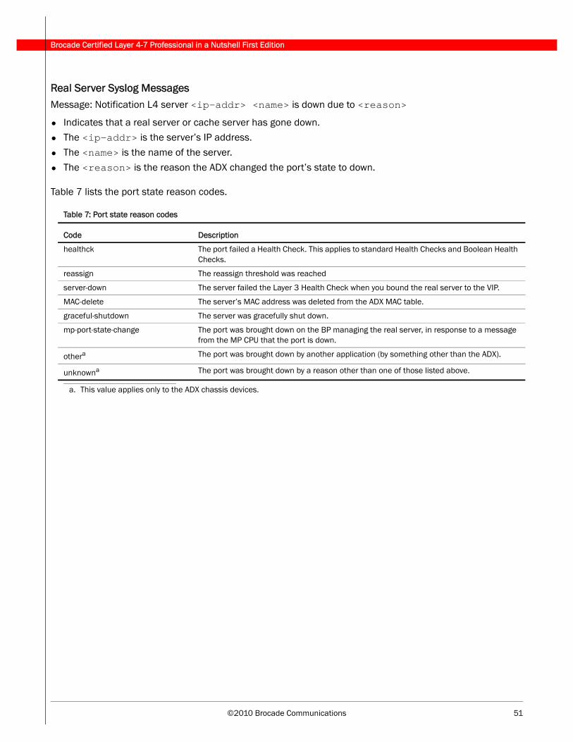
©2010 Brocade Communications 51
Brocade Certified Layer 4-7 Professional in a Nutshell First Edition
Real Server Syslog MessagesMessage: Notification L4 server <ip-addr> <name> is down due to <reason>
• Indicates that a real server or cache server has gone down.• The <ip-addr> is the server’s IP address.
• The <name> is the name of the server.
• The <reason> is the reason the ADX changed the port’s state to down.
Table 7 lists the port state reason codes.
Table 7: Port state reason codes
Code Description
healthck The port failed a Health Check. This applies to standard Health Checks and Boolean Health Checks.
reassign The reassign threshold was reached
server-down The server failed the Layer 3 Health Check when you bound the real server to the VIP.
MAC-delete The server’s MAC address was deleted from the ADX MAC table.
graceful-shutdown The server was gracefully shut down.
mp-port-state-change The port was brought down on the BP managing the real server, in response to a message from the MP CPU that the port is down.
othera
a. This value applies only to the ADX chassis devices.
The port was brought down by another application (by something other than the ADX).
unknowna The port was brought down by a reason other than one of those listed above.
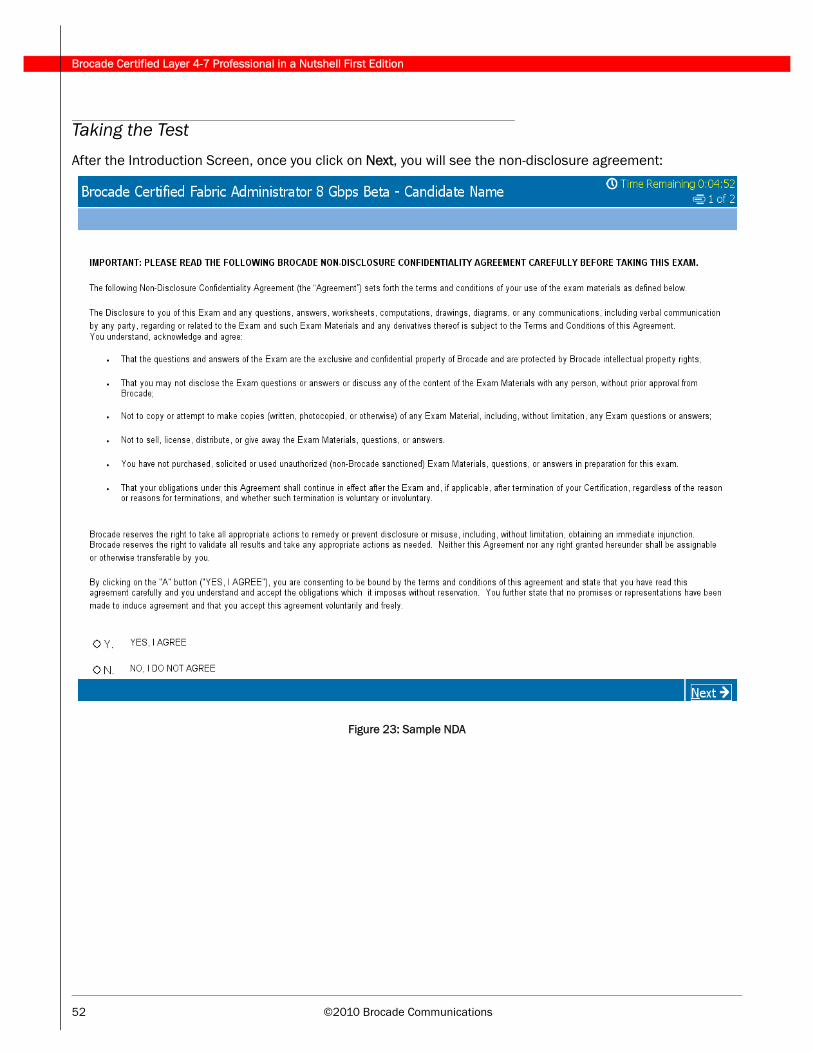
Brocade Certified Layer 4-7 Professional in a Nutshell First Edition
52 ©2010 Brocade Communications
Taking the Test
After the Introduction Screen, once you click on Next, you will see the non-disclosure agreement:
Figure 23: Sample NDA