bc standards of practice guide for air sealing and insulation retrofits
TRANSCRIPT

CLIENT For�sBC Energy Inc.
BC Hydro
BC Ministry of Energy and Mines
PREPARED BY RDH Building Engineering Ltd.
Innes Hood Consul�ng
Farrish Marke�ng Services
Construc�ve Home Solu�ons
RDH PROJECT # 7531.00
DATE December 18, 2013
BC S
tan
dard
s of P
rac�
ce G
uid
e fo
r Air S
ealin
g a
nd
Insu
la�
on
Retro
fits

December 2013 BC Air Sealing & Insula�on Retrofit Guide
Page 1
Disclaimer
This Guide, “BC Standards of Prac�ce Guide for Air Sealing and Insula�on
Retrofits” (the “Guide”) was prepared by RDH Building Engineering Ltd., Innes Hood
Consul�ng, Ken Farrish Marke�ng, and Construc�ve Home Solu�ons (the
“Consultant”) for the benefit of the group of For�sBC Energy Inc., BC Hydro, and the
BC Ministry of Energy and Mines (the “Client”).
The informa�on and opinions expressed in the Guide, or any document forming
part of the Guide, are for the sole benefit of the Client. The Client may share the
Guide with third par�es as required. Any use which a third party makes of the
Guide, is the sole responsibility of such third par�es. With respect to third par�es,
neither the Consultant or the Client, nor any other person ac�ng on their behalf (a)
makes any warranty, express or implied, or assumes any legal responsibility for the
accuracy of any informa�on contained in the Guide or for the completeness or
usefulness of any apparatus, product or process disclosed in the Guide, (b) accepts
any liability for the use of, or damages resul�ng from the use of the Guide or any
apparatus, product or process disclosed in the Guide or (c) represents that the use
of such apparatus, product or process would not infringe upon the rights of third
par�es.
Any reference in the Guide to any specific commercial product, process or service
by tradename, trademark, manufacturer or otherwise does not cons�tute or imply
its endorsement or recommenda�on by the Consultant or the Client.
Addi�onal acknowledgement is also extended to Quality Program Services for
providing technical consulta�on and weatheriza�on sites for documenta�on.
Innes Hood Consulting

BC Air Sealing & Insula�on Retrofit Guide December 2013
Page 2
Table of Contents:
BC Standards of Prac�ce Guide for Air Sealing and Insula�on Retrofits
1. Introduc�on
1.1 Scope and Use of the Guide
1.2 House as a System
1.3 BC Air Sealing and Insula�ng Retrofit Considera�ons
1.4 Health and Safety Considera�ons
2. Home Evalua�on & Selec�ng Air Sealing and Insula�on Procedures for the Home
2.1 NRCan EnerGuide Score, Measured Air�ghtness, and Opportuni�es for Improvement
3. Procedures for Air Sealing and Insula�on Energy Efficiency Measures
3.1 ADcs & Roofs
3.2 Below Grade Walls & Basements
3.3 Crawlspaces
3.4 Exposed Floors
3.5 Above Grade Walls
4. References, Specifica�ons, Standards, and Further Informa�on
5. Appendices
Contractor Checklist - Home Air Sealing and Insula�on Procedures
Contractor Checklist - Health and Safety
Glossary of Terms
3
4
5
6
7
11
12
13
16
43
49
51
54
60
63
64
65
66

December 2013 BC Air Sealing & Insula�on Retrofit Guide
Page 3
1: Introduc�on
Air sealing and insula�on weatheriza�on retrofits of exis�ng homes
are proven methods to reduce space-condi�oning energy, improve
durability, reduce u�lity bills, and reduce the gas and electric load
on the provincial u�lity providers within Bri�sh Columbia (BC).
Building enclosure weatheriza�on retrofits or Energy Efficiency
Measures (EEMs) primarily consist of air sealing and adding or
upgrading insula�on within the building enclosure, either as a
stand-alone ac�vity, or during other planned renova�on and repair
ac�vi�es. Simple weatheriza�on work can be performed by
homeowners or occupants while more advanced ac�vi�es and
extensive repairs or renova�ons typically involve a contractor.
There are many health and safety issues for both homeowners
and contractors to consider when performing work with different
building materials and when working in exis�ng homes.
Air sealing and insula�on weatheriza�on should not nega�vely
affect the durability of the structure or building enclosure.
Therefore the types of materials which are used and the order in
which steps are performed are both key considera�ons. For
example, before any insula�on can be added to a wall or roof, air
sealing must be performed within the insulated area. Failure to do
so can result in reduced insula�on effec�veness as well as moisture
accumula�on and subsequent health and durability issues. Also,
the suitability of materials for each specific applica�on is essen�al
to an effec�ve installa�on and durable long term performance.
Holis�c building performance should also be considered when
performing these types of weatheriza�on measures. For example,
improving the air�ghtness and insula�on of a house due to
weatheriza�on ac�vi�es may also require a home’s mechanical
ven�la�on system to be upgraded (or added where one is not
present). Combus�on safety and back-draKing poten�al must also
be considered, and, if necessary, make-up air should be provided
and/or appropriate equipment adjustments should be made.
There are several published Canadian and American weatheriza�on
guides geared towards do-it-yourself homeowners and contractors,
which are listed within the references sec�on of this guide. These
na�onal guides, while comprehensive, may not necessarily cover
specifics related to the construc�on of homes within BC. That is not
to say that BC is par�cularly challenging or different from a
weatheriza�on perspec�ve, but there are climate characteris�cs,
standard construc�on prac�ces, and building code requirements
which require special considera�on. These BC-specific
considera�ons are covered throughout this guide.
Infrared image of a wood-frame home in BC
iden�fying insula�on discon�nui�es and air
leakage for a weatheriza�on retrofit
Insula�on retrofit of an a�c ceiling consis�ng of
blown-cellulose over top of an air-sealing and
insula�ng layer of spray polyurethane foam
Air-sealing of an electrical penetra�on and
unsealed top-plate connec�on within an a�c.

BC Air Sealing & Insula�on Retrofit Guide December 2013
Page 4
1.1: Scope and Use of the Guide
The intent of the Guide is to consolidate best prac�ces for air sealing and insula�on retrofits (i.e. building enclosure
weatheriza�on) in BC homes. The Guide is intended to be an industry, u�lity, and government resource and be
used for training contractors in performing weatheriza�on work in BC. The informa�on may also be of interest to
homeowners and other occupants performing home retrofits with or without a contractor, though is not
specifically wriNen for this audience. Guides such as Keeping the Heat In, published by Natural Resources Canada,
or Insulate and Weatherize—Build Like a Pro Series, from the Tauton Press, are examples of publica�ons which are
more appropriate for the do-it-yourself home-owner. This guide is similar in content to contractor focused
weatheriza�on program training guides, but with specific regard to BC’s unique climate, construc�on prac�ces, and
building code requirements. It is intended that the Guide be a living document, and the input and feedback from
users of the Guide is greatly appreciated. The Guide does not cover mechanical systems, appliances, ligh�ng, or
diagnos�c tes�ng.
The Guide is wriNen for wood-frame residen�al detached, semi-
detached (e.g. duplex to quad-plex) and row-house/townhomes
within BC. Non wood-frame homes, mobile homes, and mul�-storey
mul�-unit residen�al buildings are beyond the scope of this guide.
The Guide specifically provides procedures for common air sealing
and insula�on installa�on energy efficiency measures (EEMs) for
aDcs/roofs, above grade walls, basements, crawlspaces, floors, and
the interfaces within and between these assemblies for use in BC. As
numerous home weatheriza�on guides and publica�ons already
provide a thorough background on evalua�ng homes, basic building
science, material selec�on, and complete health and safety
procedures, they are not reiterated in this guide.
The Guide does not cover the weatheriza�on or replacement of
windows or doors as this is covered within the recent Best Prac�ces
for Window and Door Replacement in Wood-Frame Buildings
published by the Homeowner Protec�on Office (cover image to
right). Addi�onally, this guide does not cover measures which relate
directly to hea�ng, cooling, and ven�la�on systems, such as duct
sealing.
It is important to note that each home and weatheriza�on project
presents unique condi�ons. This guide presents recommended best
prac�ce techniques, but it is likely that these methods will need to be
adapted to accommodate the varia�ons in each project.
This guide is wriNen in the context that the homeowner/contractor
has already decided to proceed with some air sealing or insula�on
weatheriza�on work within their home and understands the benefits
but also poten�al health and safety risks of doing so. Sec�on 1 provides a summary of the key considera�ons for
air sealing and insula�on retrofits, recommended retrofit insula�on and air�ghtness levels for BC, and a short
reminder of health and safety considera�ons. Sec�on 2 provides a brief discussion on how to use the home’s
EnerGuide Report to select appropriate energy efficiency measures (EEMs) covered within this guide. The main
focus of this guide is on the actual procedures for air sealing and installa�on of insula�on which are covered within
Sec�on 3. Sec�on 4 provides references, specifica�ons, standards, a glossary of terms, and further informa�on for
the reader.
Cover page of Best Pracces for Window
and Door Replacement in Wood-Frame
Buildings—Homeowner Protec�on Office, a
useful companion guide for weatheriza�on
contractors performing window retrofits or
replacements along with air sealing and
insula�on work covered within this guide.

December 2013 BC Air Sealing & Insula�on Retrofit Guide
Page 5
1.2: House as a System - Effect of Air Sealing and Insula�on Retrofits
A house is made up of numerous parts (e.g. structure, finishes,
mechanical systems, electrical and ligh�ng, building enclosure materials)
and contents (e.g. people, pets, plants, furniture etc.) that all interact
together as an interconnected system. This no�on of interconnectedness
and performance rela�onship is known as the “house as a system”
concept. That is, the performance of one part of a house depends on its
rela�onship with other parts of the house.
A home’s hea�ng, cooling, and ven�la�on systems and building enclosure
are par�cularly important in the context of energy efficiency. For
example, the hea�ng system will not run at op�mum performance or
efficiency if the house’s building enclosure allows a lot of air leakage or is
poorly insulated. Weatheriza�on of older homes with building enclosures
that allow significant air leakage can also poten�ally create issues that
were not previously apparent. For example, if a house is made more air
�ght then it is easier for naturally aspirated combus�on equipment
including furnaces, fireplaces and hot-water heaters to backdraK and spill
dangerous combus�on gases (including carbon monoxide) into the home
when the home is nega�vely pressurized. Sources of nega�ve pressure
include large exhaust fans for kitchen range hoods, bathroom and whole
house exhaust fans, and chimneys.
Trained weatheriza�on professionals conduc�ng home energy
evalua�ons (for example, registered energy advisors with the EnerGuide
ra�ng system) and contractors who perform air sealing and insula�on
work need to understand the interac�ons of air�ghtness, insula�on, and
mechanical and ven�la�on equipment. Being aware of the poten�al
system interac�ons and knowing possible remedial measures is necessary
when performing weatheriza�on work.
The following is a list of the key poten�al effects of air sealing and insula�on retrofits on home performance
highligh�ng the system interac�ons that can occur.
• Air sealing work makes a home less draKy and more comfortable, and reduces space condi�oning costs.
• Air sealing work will seal holes that may have previously provided natural ven�la�on within the home.
• A more air�ght home means that exhaust fans and un-sealed combus�on appliances will create higher nega�ve pressures on the building enclosure unless dedicated make-up air is provided.
• A nega�ve pressure on the building enclosure can cause back draKing and poten�ally harmful spillage of combus�on gases from un-sealed combus�on appliances and fireplaces unless provisions are made to provide make-up air for the appliance to neutralize the pressure or the unit is directly vented to outside.
• Adding insula�on will reduce space condi�oning costs and will make indoor spaces more comfortable and interior surfaces less prone to condensa�on and subsequent deteriora�on.
• Adding insula�on to walls, roofs, and floors can cause condensa�on to occur within concealed spaces if vapour diffusion and air leakage control is not properly addressed, or incorrect materials are used.
• Some insula�on and sealant materials contain VOCs and other harmful chemicals and must be used carefully and properly ven�lated un�l cured.
• Care must be taken when selec�ng building materials as some building materials are incompa�ble with each other and with exis�ng building components such as electrical wiring and plas�cs.
All the parts of the house including its contents
and occupants interact together to form an
integrated system - this is impera�ve to
understand when performing air sealing and
insula�on work. This guide covers air sealing
and insula�on weatheriza�on work for all
parts of the house from the basement to the
a�c.

BC Air Sealing & Insula�on Retrofit Guide December 2013
Page 6
1.3: BC Air Sealing and Insula�ng Retrofit Considera�ons
Over a million detached and low-rise wood-frame
homes were constructed within BC over the past
century. The construc�on of these homes has
evolved over the past decades in terms of insula�on
levels and building enclosure air�ghtness. Older
homes tend to be poorly insulated and more air
leaky compared to new homes. In general, older
homes will benefit more from insula�on upgrades, as
insula�on levels before the 1980s were rela�vely low
or non-existent, in par�cular in basements and
crawlspaces. ADc insula�on levels within houses
constructed before the 1990s is also typically low.
Commonly, however, even newer homes
constructed within the past decade will benefit from
air sealing work as this has been something that is
oKen overlooked during construc�on in BC. Air
sealing is unlikely to provide a significant benefit for
new homes which were air�ghtness tested during
construc�on and have an air exchange rate of less
than 2 ACH50.
The op�mal amount of insula�on that should be used
in a wall, floor, or roof depends on where the home is
located within BC. Houses within the colder regions of the BC Interior and North need to have more insula�on and
be more air�ght than houses on the South Coast in order to be comfortable in the winter�me and use an as liNle
space-hea�ng energy as possible to maintain a comfortable indoor environment for occupants.
The following air�ghtness targets and insula�on levels (effec�ve assembly R-value) are recommended for homes
within BC based on 2012 BC Building Code requirements, typical construc�on prac�ces, and insula�on retrofit
poten�al. Upgrading a house to this level of performance can be costly, and the returns on investment for some
levels of insula�on or sealing may not provide payback (for the homeowner in terms of u�lity bill savings)
depending on the ini�al insula�on levels, the cost of the project, where the house is located, and what fuel is used
for hea�ng. Consult with the BC Building Code and various green building standards for guidance regarding
required and op�mal insula�on levels.
Hea�ng Degree Day (HDD) map of BC showing approximate climate
zones 4 through 8 as defined within the Na�onal Energy Code for
Buildings (NECB) and new Bri�sh Columbia Building Code (BCBC).
Note that actual HDD values are found within the BC Building Code
and are available online for many municipali�es.
Wood-Frame Building
Enclosure Assembly
Zones 4&5 -
<4000 HDD
Zone 6 -
4000-4999 HDD
Zone 7A -
5000-6000 HDD
Zone 7B & 8 -
>6000 HDD
A<c Spaces R-40 R-50 R-60 R-60
Cathedral or Flat Roofs R-30 R-30 R-35 R-40
Above Grade Walls R-20 R-25 R-25 R-30
Below Grade Walls R-20 R-20 R-25 R-25
Suspended Floors R-25 R-30 R-40 R-50
Air �ghtness (ACH50) <3 ACH <2.5 ACH <2 ACH <1.5 ACH
Slab on Grade Floors R-10 R-15 R-20 R-25
8 > 7,000 HDD
7B 6,000 to 6,999 HDD
7A 5,000 to 5,999 HDD
6 4,000 to 4,999 HDD
5 3,000 to 3,999 HDD
4 < 3,000 HDD

December 2013 BC Air Sealing & Insula�on Retrofit Guide
Page 7
With proper precau�ons and training, air sealing and insula�on weatheriza�on work on homes should pose liNle to
no threat to the health and safety of the contractor or the occupants of the home; however, many building materials
and tools if improperly used can be dangerous to the user or to building occupants, or can damage the building.
Therefore, contractors must read and follow the manufacturer’s recommended safety and installa�on procedures
when working with building materials and tools. Wherever possible, less harmful and lower VOC air sealing and
insula�on materials should be used, par�cularly if materials will be exposed to interior living space. The following
pages summarize some of the key points to consider with references provided for further informa�on and
occupa�onal health safety procedures. A health and safety checklist is provided for contractors in the appendices
which covers some of the major considera�ons. The health and safety considera�ons and prac�ces iden�fied in this
guide are neither comprehensive nor complete. Those performing weatheriza�on work such as that discussed in this
guide should always be appropriately trained and aware of the safety risks associated with the work.
Structural Elements and Connec�ons
Structural elements of the home should not be compromised during weatheriza�on work even if it may be necessary
to cut, drill, or relocate wood structural elements during renova�on work. Contractors should avoid cuDng wood
elements such as studs, trusses, joists and beams when air sealing or insula�ng unless a structural engineer has been
retained to review the modifica�ons and suggest remedial or reinforcing techniques.
Ven�la�on of the Home
Air sealing work seals openings within the building enclosure which may have previously been relied upon for natural
or passive ven�la�on in the home. Inadequate ven�la�on can lead to indoor air quality concerns and moisture
problems, and therefore a properly func�oning and sized mechanical ven�la�on system is necessary. Further
informa�on can be found within numerous resources on ven�la�on system design including Chapter 18 of the new
Canadian Home Builder’s Associa�on Builders’ Manual and the TECA Quality First Ven�la�on Guidelines.
Ven�la�on while Performing Work
Many sealants, adhesives, and spray polyurethane foams release VOCs and other poten�ally harmful chemicals
when curing. The product manufacturers installa�on and safety procedures should be followed when performing
work, and ven�la�on should be provided as required poten�ally including opening windows or using temporary
ven�la�on fans as appropriate. In some cases, for example when using large quan��es of spray polyurethane foam
in aDcs, roofs, or walls, contractors need full respiratory equipment while in the work area and homeowners may
need to leave the house for up to 24 hours aKer spraying.
Asbestos Containing Products and Vermiculite Insula�on
Asbestos may be found within the building products used in many older homes, par�cularly those built before the
1990s. Vermiculite insula�on, asbestos cement board siding, asbestos pipe insula�on, drywall joint compound,
stucco, some older window puDes are a few of the many building products that may contain asbestos fibres.
Undisturbed materials contained within walls or aDc spaces pose liNle risk to occupant health; however, if exposed
or disturbed as part of a weatheriza�on program these materials can cause health risks to both the contractor and
homeowner. At minimum, contractors and homeowners should consult the following documents prior to
undertaking weatheriza�on work: It’s Your Health—Vermiculite Insula�on Containing Amphibole Asbestos, published
by Health Canada, and Asbestos Hazards When Renova�ng Older Homes and Safe Work Prac�ces for Handling
Asbestos, both published by WorkSafeBC along with the WorkSafeBC.com website for further informa�on.
1.4: Health and Safety Considera�ons

BC Air Sealing & Insula�on Retrofit Guide December 2013
Page 8
1.4: Health and Safety Considera�ons
Lead Paint
Lead can be found within many paints and coa�ngs used in buildings un�l the 1980s. Lead-containing paints and
coa�ngs do not present a hazard if they are leK intact; however, if weatheriza�on work damages or removes
materials containing lead then appropriate safety measures must be followed. Further informa�on can be found in
Lead-Containing Paints and Coa�ngs, published by WorkSafeBC, which is available online (www.worksafebc.com).
Sprayfoam Insula�on
Spray polyurethane foam (SPF) is a commonly used air sealing and insula�on material for weatheriza�on work and
this guide suggests its use in various applica�ons. Exposure to isocyanates and other chemicals within the
sprayfoam during the curing period or for some �me aKer installa�on may cause health effects in some people.
Care must be taken to control exposure to contractors and the homeowner including possibly vaca�ng the home
while sprayfoam is being applied and for up to 24 hours for large sprayfoam applica�ons. In addi�on, some
sprayfoam types (closed cell, medium density products) can only be applied in liKs of up to 2” at a �me and not be
used to fill closed cavi�es, with a cooling off period in-between liKs for thicker applica�ons. Sprayfoam should
always be installed by a trained contractor and this guide does not provide informa�on or instruc�on on
installa�on and safety procedures for spray polyurethane foams. Health and safety informa�on should be
provided by sprayfoam manufacturers; however, the US EPA also has an unbiased website on SPF within the home
(hNp://www.epa.gov/dfe/pubs/projects/spf/spray_polyurethane_foam.html).
Materials Containing Solvents and VOCs
Sealants, adhesives, and other products used for air sealing and insula�on weatheriza�on work may contain
solvents and vola�le organic compounds (VOCs) which can affect contractor or homeowner health and safety and
are flammable. Low VOC op�ons for many adhesives and sealants are available and should be used where they will
be exposed indoors, though for some applica�on, the use of higher VOC products may be required. Ensure that
products that are exposed indoors, such as sealants and paints, are low VOC formula�ons, otherwise the odor may
irritate the occupants. Addi�onal health and safety informa�on can be found by reviewing the product literature
and MSDS forms provided by the product manufacturer.
Radon Gas
Radon is a colourless, odorless, tasteless radioac�ve gas that is produced by the breakdown of uranium in soil and
rock below a house. Radon is present in outdoor air at low concentra�ons and is harmless; however, within an
enclosed house, radon can build up and create a long-term health risk to occupants. The concentra�on of radon
within a home depends on the radon concentra�on within the soil below the house, the pressuriza�on of the
home (i.e. depressuriza�on pulls radon in through founda�on cracks), and the house ven�la�on rate. Air sealing
and insula�on weatheriza�on work within a basement or crawlspace (e.g. sealing founda�on cracks and gaps) can
help reduce the concentra�on of radon in the home, though at the same �me, air sealing work can lead to a more
air�ght home which is then prone to more depressuriza�on and poor ven�la�on (unless addressed). Radon is more
of a concern for homes and east of the Coast Mountain Range in the Interior of BC than it is for homes in coastal
BC. When performing weatheriza�on work in homes within poten�ally affected areas, basement and crawlspace
sealing is recommended before aDc or above grade work. Where radon is a concern, tes�ng should be performed
and is rela�vely inexpensive. Further informa�on can be found at HealthLinkBC (hNp://www.healthlinkbc.ca/
healthfiles/hfile42.stm).

December 2013 BC Air Sealing & Insula�on Retrofit Guide
Page 9
1.4: Health and Safety Considera�ons
Mould, Fungal Growth, and Moisture Damage
Fungal contamina�on and mould can occur within homes and concealed building enclosure assemblies if the
materials are exposed to elevated rela�ve humidity levels (typically above 80% RH for extended periods) and/or
condensa�on. Organic materials such as paper faced drywall and wood are suscep�ble to fungal growth in the
home. Fungal growth is also common in bathrooms, but easily cleaned by regular household cleaning. Fungal
growth on window frames may occur if excessive condensa�on occurs as a result of high indoor rela�ve humidity
levels. Fungal growth is also commonly found within crawlspaces, aDcs, and other damp spaces as a result of
elevated rela�ve humidity levels, condensa�on, rainwater, and plumbing and appliance leaks. Depending on the
severity and dura�on of the weDng, fungal growth can lead to decay and deteriora�on of wood components.
Moisture damaged wood is unfortunately common within many BC homes and is oKen uncovered during
weatheriza�on work.
If significant fungal contamina�on or mould is present or suspected within the home it must be removed and
cleaned and the contribu�ng source addressed prior to any air sealing and insula�on weatheriza�on work. This
means if an aDc or crawlspace is found to be mouldy, the problem should be addressed prior to or as part of the
air sealing and insula�on work. To control and reduce the poten�al for mould growth, indoor moisture sources and
indoor humidity must be controlled. This can be achieved by the combina�on of a proper ven�la�on system with
good distribu�on within the home, and source moisture control. Addi�onal informa�on can be found in Keeping
the Heat In, published by Natural Resources Canada.
A good reference on wood durability including procedures for the remedia�on of moisture damaged wood
buildings can be found at the Bina�onal SoKwood Lumber Council website (hNp://www.soKwoodlumber.org/why-
wood/wood-durability.html). Where mould growth is severe or moisture damage is extensive, a professional
specializing in mould clean-up and structural repair should be retained. The document Guidelines on Assessment
and Remedia�on of Fungi in Indoor Environments published by the New York City Department of Heath and Mental
Hygiene is a good reference for remedia�on procedures. When cleaning up mould contaminated building
materials WorkSafeBC OHS regula�ons should be followed (Guidelines Part 4 - Indoor Air Quality).
Combus�on Safety
Air sealing and insula�on weatheriza�on work can affect the combus�on safety of a home. Appliances such as gas
or wood-burning fireplaces, gas or oil burning appliances such as a boilers, furnaces, or water heaters that have
natural draK chimneys may rely on natural air leakage through the enclosure to provide the make-up air for
combus�on. Some homes may have dedicated combus�on air ducts (which must not be sealed during
weatheriza�on work). If air sealing and weatheriza�on work is performed on a home with a natural draK chimney
then this make-up air may be reduced to a point where this equipment or fireplace may backdraK and spill
combus�on gases into the home. When weatheriza�on work is undertaken, a direct supply of make-up air for
these systems may be required. In homes with unvented fuel heaters or unvented gas fireplaces it can be more
difficult to provide make-up air, and these may need to be removed prior to weatheriza�on work.
Weatheriza�on work within homes with gas, oil, or wood-burning equipment requires special considera�on and
combus�on safety tes�ng to be performed. Guidance for addressing combus�on safety, tes�ng, and remedial
measures are beyond the scope of this guide. Several references are provided within Sec�on 5 at the end of this
guide. Contractors performing weatheriza�on work should be trained about these issues prior to performing any
work.

BC Air Sealing & Insula�on Retrofit Guide December 2013
Page 10
1.4: Health and Safety Considera�ons
Gas Safety
Air sealing and insula�on weatheriza�on work typically does not require the movement or reloca�on of gas lines or
equipment; however, if a smell of gas is detected or gas equipment work is required, proper procedures must be
followed by a trained contractor. For example, modifica�ons may be required aKer a failed combus�on safety test
on a weatheriza�on project. BC specific informa�on can be found at the BC Safety Authority (hNp://
safetyauthority.ca/regula�ons/gas) as guidance is not provided here.
Electrical Wiring
Care must be taken when working around electrical wiring as not to receive a shock, damage the wiring, or cause a
fire. Air sealing materials such as sprayfoam should never be applied within electrical boxes or come into contact
with bare wires, so use of these materials around electrical connec�ons requires special aNen�on. Always follow
product manufacturers’ instruc�ons and warnings, and hire an electrician if any electrical work is required as part
of the weatheriza�on work. This type of work can be common where new exhaust fans may be installed to provide
mechanical ven�la�on aKer air sealing work is performed.
Some older homes within BC may s�ll have ac�ve knob and tube wiring. The house must be rewired and the knob
and tube wiring decommissioned in the affected areas prior to the aDc being air sealed and insulated. If in doubt,
hire an electrician to review the wiring and perform any necessary work.
Other Considera�ons
Weatheriza�on work can some�mes uncover other issues within a house. For example, exhaust fans may be
directly vented into aDcs instead of outdoors, or a roof, crawlspace, or basement may be found to be leaking. In
these cases, these problems must be addressed before or as part of the weatheriza�on work.

December 2013 BC Air Sealing & Insula�on Retrofit Guide
Page 11
2: Home Evalua�on & Selec�ng Air Sealing and Insula�on Procedures
While almost every part of an old building can be beNer
insulated and made more air�ght, it is important to know
which Energy Efficiency Measures (EEMs) can have the largest
effect on the performance of the home.
The adjacent figures shows a schema�c of a mul�-storey
home with a basement and crawlspace, two floors of living
space, and an aDc. The first concept to understand is the role
stack effect plays in the air movement of the house. At the
boNom of the house, cold air is drawn in to the house, and at
the top, air is pushed out into the aDc. As a result, air sealing
and insula�ng at the boNom (i.e. basements and crawlspaces)
and at the top (i.e. aDcs and roofs) of a house should be
priori�zed, and these areas are also oKen the easiest to
access within unfinished spaces. In the middle of the house,
at the neutral pressure plane, air is not moving in or out the
house as much, and air sealing can be difficult without
disrup�on to interior finishes.
Air Sealing
To start, sealing all of the large holes in the house will have
the biggest effect. Plumbing, duct work, chimney chases,
electrical, and other service penetra�ons not intended for
airflow or ven�ng should be sealed where possible, no maNer
where they are in the house. Though it seems obvious,
service penetra�ons are usually the loca�ons of the biggest
and leakiest areas of a house.
Once big holes are sealed, the focus can be shiKed to smaller,
less obvious holes. At the basement or crawlspace, the rim joists should be sealed as they can allow significant
amounts of air into the home where the exterior wall meets the rim joist, and where the rim joist meets the
founda�on. Since cold air is drawn through these areas, air sealing can improve the thermal comfort of the home,
and decrease hea�ng costs.
At the top of the house, air leakage into the aDc occurs through pot lights, exhaust fans, and par��on walls. Pot
lights can be the biggest air leakage path of the small holes since a hot light bulb will draw air up, heat it, and then
pull it through the housing into the aDc like a small chimney. Unsealed service penetra�ons like plumbing stacks
and vents as well as exposed drop ceilings and service shaKs , should also be sealed.
Insula�ng
Where possible, the whole house should be insulated using standard prac�ce insula�ng techniques to increase the
thermal efficiency of the home. Insula�on work must be done without compromising the durability of the exis�ng
wood-frame structure by crea�ng a risk of condensa�on weDng, high rela�ve humidity condi�ons, or moisture
entrapment. All insula�on work begins with air-sealing. Never insulate a wall, roof, or floor without first making
sure the air leaks within the vicinity are addressed.
Typically the aDc followed by the crawlspace are the most cost effec�ve loca�ons to perform insula�ng work.
Unfinished basements are also easy to insulate. Insula�ng above and below grade finished walls is much more
involved and is oKen beNer to perform at the �me of other renova�ons, repairs or cladding work.
Schema�c of a typical 2 storey wood-frame house over part
basement and crawlspace with a ven�lated a�c roof.
Arrows show typical air leakage loca�ons to review and
address during weatheriza�on work.

BC Air Sealing & Insula�on Retrofit Guide December 2013
Page 12
2.1: Energy Performance Assessments and EnerGuide Ra�ng System
An assessment of the energy performance of a home should be conducted prior to performing weatheriza�on
work. These types of evalua�ons help to determine the suitability of a house for weatheriza�on improvements
and to priori�ze different energy efficiency measures. Addi�onally, this assessment in conjunc�on with a
subsequent “post-retrofit” assessment upon comple�on of the weatheriza�on work can provide detailed
informa�on regarding the effec�veness of the weatheriza�on measures. In some cases this secondary assessment
may also qualify a house for rebates as part of part of a weatheriza�on program.
While it can be difficult to economically jus�fy weatheriza�on measures implemented in isola�on, the incremental
costs of these measures are significantly lower when implemented as part of previously planned renova�on work,
or when rebates are available. Cost effec�veness for the homeowner can also be more easily predicted when a
thorough energy performance assessment is conducted prior to star�ng the upgrades.
Steps for effec�ve use of energy performance assessments in the weatheriza�on process:
1. Assess the House Prior to Weatheriza�on — An energy assessment professional should conduct an energy
assessment of the house prior to weatheriza�on work. The assessment should include evalua�on of the
building enclosure including insula�on, windows, and doors, as well as of the hea�ng, cooling, ven�la�on,
and hot water systems of the house. The assessment should also include a whole building air�ghtness test
to measure the air�ghtness of the house. Finally, the assessor should model the energy consump�on of the
house and generate relevant performance metrics, poten�ally including an EnerGuide ra�ng.
2. Implement Weatheriza�on Measures — Based on the assessment of the house, weatheriza�on (energy
efficiency) measures should be selected and implemented including air sealing and installa�on of insula�on.
3. Assess the House AFer Weatheriza�on — A energy assessment professional should conduct a follow-up
assessment of the house. This assessment should confirm implementa�on of the selected energy efficiency
measures. The assessments prior to and aKer weatheriza�on can then be used to apply for relevant rebates.
An EnerGuide Home Evalua�on provides a homeowner and contractors with detailed informa�on on a house and
also produces an EnerGuide ra�ng. An EnerGuide ra�ng is a standard measure of a house’s energy performance
that enables comparison to other houses. The ra�ng is based on house and equipment energy efficiency, house
loca�on, and house size. EnerGuide ra�ngs and air�ghtness levels are presented in the following table for various
house types based primarily on age of construc�on. Note that the EnerGuide Ra�ng System is regularly updated so
the table below is subject to change. Addi�onal informa�on regarding the EnerGuide ra�ng system is available
online (hNp://oee.nrcan.gc.ca/).
Type of House Typical EnerGuide Score
(0 to 100, higher is beGer)
Typical Air�ghtness
(ACH50, lower is beGer)
Zero Energy Home > 90 0.5
Energy Efficient Home 80 to 84 1.5
New Home 72 to 78 3 to 5
Built 1980 to 2010 66 to 72 5 to 10
Built 1960 to 1979 55 to 66 7 to 10
Built Before 1960 < 55 10 to 20

December 2013 BC Air Sealing & Insula�on Retrofit Guide
Page 13
3: Procedures for Air Sealing and Insula�on Energy Efficiency Measures
Step by step air sealing and insula�on energy efficient
measure procedures are provided within this sec�on of
the Guide. Where the work is more complex and
beyond the scope of this guide (such as full house
exterior wall insula�ng), less detailed conceptual level
procedures are provided. For these larger scale
measures, typically a building enclosure design will
need to be performed by a home designer, architect,
engineer, or contractor.
Each procedure contains a list of the necessary
materials and tools to perform the job along with a step
by step descrip�on of the work. It may also be possible
to use alternate materials so long as the intended
performance is maintained. Contractors should also
refer to the health and safety checklist provided in the
appendix.
The Guide starts with a thorough coverage of accessible
aDc air sealing measures as these are typically the
easiest and most cost effec�ve to perform as part of
weatheriza�on efforts. Next, aDc insula�on upgrades,
and air sealing and insula�on op�ons for cathedral
ceilings are discussed. Cathedral ceilings are more
difficult to seal or insulate without significant interior or
exterior construc�on work. Below grade walls and
crawlspaces are then discussed in detail, as they are
accessible and rela�vely easy to air seal and insulate.
Exposed floor solu�ons are also covered. Finally, as
weatheriza�on work does not typically focus its efforts
on above grade wall air sealing and insula�on
procedures, this work is only briefly discussed, and
addi�onal references and recommended solu�ons for
BC are provided for those interested in pursuing this
more intensive and disrup�ve work.
For each of the procedures, it is important that air
sealing work always be performed prior to insula�ng.
This is to prevent condensa�on and moisture related
problems from occurring as a result of the added or
upgraded insula�on.
Where more extensive work is planned such as window
or cladding replacement or wall and roof upgrades,
homeowners should consult design professionals as this
work is more complex and may require a building
permit.
Cathedral ceiling air sealing loca�ons discussed within the Guide
A�c air sealing loca�ons and EEMs covered within the Guide
Above grade wall air sealing loca�ons discussed within the Guide
Below grade wall air sealing loca�ons discussed within the Guide

BC Air Sealing & Insula�on Retrofit Guide December 2013
Page 14
3: Air Sealing and Insula�on Energy Efficiency Measures Covered
within the Guide
The following is a list of the air sealing and insula�on energy efficiency measures (EEMs) covered within this guide.
3.1 A<cs & Roofs
Accessible A<c Ceiling
3.1.1 Recessed Pot/Can Lights
3.1.2 Bathroom Fan and Duct
3.1.3 Kitchen Range, Dryer, or Other Exhaust Duct
3.1.4 Fireplace or Other Combus�on Appliance Duct
3.1.5 Masonry Chimney
3.1.6 ADc Hatch
3.1.7 Wall Top Plate/Top Plate Electrical and Plumbing Penetra�ons
3.1.8 Large Openings, ShaKs, or Exposed Drop Ceilings
3.1.9 ADc Knee Walls
3.1.10 Topping up Exis�ng Insula�on
3.1.11 Flash and Fill Insula�on
Vaulted Ceilings and Inaccessible A<cs
3.1.12 Air sealing Measures from Interior
3.1.13 Interior vs. Exterior Insula�on Upgrade Considera�ons
3.1.14 Interior Insula�on Upgrades with Interior Renova�ons
3.1.15 Exterior Insula�on Upgrades with Re-roofing Work
3.2 Below Grade Walls
3.2.1 Air sealing Measures from Interior
3.2.2 Interior vs. Exterior Insula�on Upgrade Considera�ons
3.2.3 Interior Insula�on Upgrades when Performing Interior Renova�ons
3.2.4 Exterior Insula�on Upgrades when Performing Exterior Repairs or Renova�ons

December 2013 BC Air Sealing & Insula�on Retrofit Guide
Page 15
3: Air Sealing and Insula�on Energy Efficiency Measures Covered
within this Guide
Con�nued...
3.3 Crawlspaces
3.3.1 Air sealing and Insula�ng Suspended Floors in Ven�lated Crawlspaces
3.3.2 Vented to Unvented Crawlspace Conversions
3.4 Exposed Floors
3.4.1 Air sealing and Insula�ng Overhanging Floors & Bay Window Floors
3.4.2 Air sealing and Insula�ng Protected Porches over Living Space
3.5 Above Grade Walls
3.5.1 Air-sealing Measures from Interior
3.5.2 Stud Wall Fill Insula�ng - Cellulose Fill from Interior or Exterior
3.5.3 Interior vs. Exterior Wall Insula�on Upgrade Considera�ons
3.5.4 Interior Insula�on Upgrades when Performing Interior Renova�ons
3.5.5 Exterior insula�on Upgrades when Performing Exterior Renova�ons and Re-cladding

BC Air Sealing & Insula�on Retrofit Guide December 2013
Page 16
3.1: A<cs and Roofs
Air Sealing and Insula�on Measures for Accessible A<c Ceiling Spaces
All aDc/ceiling Energy Efficiency Measures (EEMs) begin with some ceiling plane air sealing work followed by
insula�on top-ups or insula�on replacement. With proper prepara�on, air-sealing sprayfoam insula�on may
alternately be used for both purposes. To ensure adequate adhesion when sealants or sprayfoam are used for air
sealing, all areas requiring adhesion must be cleaned. Guidance is provided here to first seal all common ceiling
penetra�ons and interfaces and then to upgrade insula�on levels. Addi�onal procedures and a good companion
document for the work as covered here is the Guide to A�c Air Sealing by Building Science Corpora�on.
BEFORE YOU START - Do Not Proceed If:
• The a<c has ac�ve knob and tube wiring
• The a<c has vermiculite insula�on
• The a<c has bathroom other exhaust fans vented into the a<c
• The a<c has mould growth or water stains
• The house has a leaking roof
• The house has an unvented fireplace
• The house has significant moisture or mould issues
3.1.1 Recessed Pot/Can Lights
3.1.2 Bathroom Fan & Duct
3.1.3 Kitchen Range, Dryer, or Other Exhaust Duct
3.1.4 Fireplace or Other Combus�on Appliance Duct
3.1.5 Masonry Chimney
3.1.6 A<c Hatch
3.1.7 Wall Top Plate & Plumbing/Electrical Penetra�ons
3.1.8 Large Openings, ShaFs, or Drop Ceilings
3.1.9 A<c Knee Walls
IMPORTANT NOTE:
There are some important openings within the a<c that should not be sealed. Soffit, ridge, and gable vents are all inten�onal openings that must be kept open for ven�la�on.
3.1.1
3.1.2
3.1.5
3.1.7
3.1.3
3.1.6
3.1.4
3.1.8
3.1.9

December 2013 BC Air Sealing & Insula�on Retrofit Guide
Page 17
3.1.1: A<cs and Roofs: Recessed Pot/Can Lights
Air Sealing Procedure - Page 1 of 2
Recessed pot/can light housings are one of the most common air leakage points
through the ceiling plane into the aDc. Air leakage occurs between the housing
and the drywall (and poly if present) and through the fixture housing holes and
its electrical connec�ons. Light housings come either rated for insula�on contact
(IC rated) or not, and either air�ght (AT) or not. Most new homes will u�lize AT/
IC rated fixtures; however, fixtures within most older homes are non-air�ght and
non-IC rated housings. IC rated fixtures allow for direct contact with insula�on
(up to 8” deep) whereas non-IC rated fixtures requires nothing to be within 3” of
all sides and top of the housing to allow for heat dissipa�on.
This procedure is for leaky non IC rated pot lights, common in most older homes.
A similar procedure could also be followed for leaky IC rated lights. If the light
housing is air�ght and has been properly sealed to the ceiling air barrier (either
the polyethylene, if present, or drywall) then this procedure is not required.
Proprietary fire-rated air-�ght housings are also available which may simplify
this procedure. The homeowner may alternately consider replacing the light
housings with AT/IC rated fixtures.
MATERIALS NEEDED
• 5/8” gypsum drywall
• Polyurethane sealant
• Sheathing tape
• Spray polyurethane sealant (spray can or 2-part froth pack)
RECOMMENDED TOOLS
• U�lity knife
• Caulking gun
• Drywall saw
PROCEDURE
Expose the ceiling gypsum board approximately
12” on both sides of the recessed can light.
Add sealant at the joist to gypsum board joint,
extending past the ends of the gypsum board box
to air seal the gap between the joist and drywall
(or poly if present).
Create the gypsum board boxes outside the aDc:
I. Precut 5/8” piece of drywall 42” long by 22
1/2” wide (for 24” ceiling joist spacing) or
14 1/2” wide (for 16” ceiling joist spacing).
II. Score back side of gypsum board at 12”
from ends.
III. Break along scored lines and form an
inverted U-shape of gypsum to keep
insula�on 3” from light fixture housing.
IV. Cut 2 gypsum board end closures, 18” long
by 8.5” wide (for 2x4 framing).
1 2 1
3
2
Non-IC rated air leaky pot light
Fold Down 22.5”
42”
12”
18”
12”
Score
3

BC Air Sealing & Insula�on Retrofit Guide December 2013
Page 18
3.1.1: A<cs and Roofs: Recessed Pot/Can Lights
Air Sealing Procedure - Page 2 of 2
PROCEDURE (Con�nued)
Install gypsum board box within aDc between
the ceiling joists. Notch the drywall box to fit
around wiring and other framing etc.
Install gypsum board end closures.
Tape seams of the gypsum board box.
Seal the box to the ceiling (or poly if present) with
sealant and fill notches and gaps with sprayfoam
sealant.
Inspect the box to ensure all gaps and joints are
taped/sealed and air�ght.
Replace exis�ng insula�on around the sides.
Insula�on is not to be placed on top of the box
unless the light is IC rated.
COMPLETE
4
5
6
9
7
4
5
6
7
8
9
KEY ITEMS TO CONSIDER
DO
• Ensure clearance between the pot light housing and
the drywall box is a minimum of 3”.
• Ensure all electrical wires are properly aGached to
the fixture, secured to the framing, and that the
penetra�ons through the box are sealed.
• Modify dimensions as necessary to accommodate
on site condi�ons while maintaining necessary
clearances.
DO NOT
• Cover the top of the box with insula�on. The box is
leF uncovered so that heat can dissipate from the
pot light fixture. Only IC-rated fixtures can be insu-
lated over top.
HOMEOWNER TIPS
• Consider replacing exis�ng light bulbs with compact
fluorescents or LED lamps to reduce heat build-up
and save electrical energy.
• As an alternate to this procedure, consider installing
air�ght IC rated pot lights. These can be insulated on
top and will save energy and reduce poten�al for
condensa�on.

December 2013 BC Air Sealing & Insula�on Retrofit Guide
Page 19
3.1.2: A<cs and Roofs: Bathroom Fan and Duct
Air Sealing Procedure - Page 1 of 2
Bathroom exhaust fan housings and duct connec�ons
are common air leakage points through the ceiling plane
into the aDc. Air leakage occurs between the housing
and the drywall (and polyethylene air barrier if present)
and through the fixture housing holes and electrical
connec�ons into it. Air leakage can also occur at the duct
connec�on into the housing. It is important to seal this
connec�on in order to stop warm moist air from ven�ng
into the aDc.
This procedure is for exhaust fans mounted to the side of
a joist. If the exhaust fan is mounted in the middle of the
joist space the procedure can be adjusted accordingly.
Note: See exhaust duct air-sealing and insula�on
procedure 3.1.3 if exhaust ducts are not insulated or are
discharging within the a�c.
MATERIALS NEEDED
• 1.5” XPS foam insula�on board (Alternately, gypsum drywall can be used)
• Polyurethane sealant
• Sheathing or foil tape
• Spray polyurethane sealant (spray can or 2-part froth pack)
RECOMMENDED TOOLS
• U�lity knife
• Caulking gun
PROCEDURE
Expose the ceiling gypsum board approximately
12” on both sides of the fan housing.
Note: If the bathroom fan is mounted to the side
of a ceiling joist (as shown) it may be beneficial to
temporarily move the housing out of the way in
order to seal the joist to gypsum board joint. (See
Recessed Pot/Can Lights).
Create a 5-sided box with extruded polystyrene
which will fit over the fan housing leaving a
minimum 1/2” clearance around the housing.
Scribe and cut access in the box for the exhaust
duct outlet.
1
2
1
2
Bathroom exhaust fan ven�ng into the a�c. Condi�ons such
as this should be remedied prior to or as part of air sealing
and insula�on work.

BC Air Sealing & Insula�on Retrofit Guide December 2013
Page 20
PROCEDURE (Con�nued)
Seal all edges of the insula�on enclosure with
sheathing tape or foil tape.
Seal the enclosure to the ceiling gypsum board
and joists with sealant.
Seal around the duct penetra�on and other
notches with sprayfoam.
Replace exis�ng insula�on and, if desired, install
addi�onal insula�on.
COMPLETE
3
3.1.2: A<cs and Roofs: Bathroom Fan and Duct
Air Sealing Procedure - Page 2 of 2
4
5
6
KEY ITEMS TO CONSIDER
DO
• Ensure the exhaust duct is sealed, insulated, and is
not collapsed throughout the whole a<c space.
• Ensure all electrical wires are properly aGached to
the fan and secured to the framing. If they are not,
consult an electrician.
DO NOT
• AGempt to directly seal or alter the fan housing.
• Make electrical repairs without consul�ng an elec-
trician. Always ensure power is shut off at the
breaker before working with wiring.
HOMEOWNER TIPS
• Keep the exhaust fan clean to ensure adequate
ven�la�on. Use a vacuum or duster to regularly
clean the fan and inside the housing.
• Consider replacing an old and noisy bathroom fan
with a new quieter and more energy efficient model
at the �me of this work. Look for a fan that is Energy
Star® qualified with a noise level of less than 1 sone.
3
4
6
5

December 2013 BC Air Sealing & Insula�on Retrofit Guide
Page 21
3.1.3: A<cs and Roofs: Kitchen Range, Dryer, or Other Exhaust Duct
Air Sealing Procedure - Page 1 of 2
Kitchen range, dryer, bathroom fan, or other exhaust
ducts that don’t vent combus�on air can be air sealed
with rela�ve ease. Besides making the ceiling penetra�on
air�ght, it is also important to air seal the duct itself to
prevent warm moist air from ven�ng into the aDc. All
mechanical air ducts (both supply and exhaust) running
through the aDc should also be insulated in order to
avoid condensa�on within the duct and reduce heat gain
into the aDc, which can be an issue in colder regions
where it may contribute to ice-damming. Flex duct that is
not insulated should be replaced with insulated ducts,
and rigid ducts should be covered with an insula�on
sleeve.
This air sealing procedure is for a range or other exhaust
duct that penetrates the ceiling without a framed shaK.
MATERIALS NEEDED
• Spray polyurethane sealant (2 –part froth pack) or polyurethane sealant
• Insulated duct sleeve (2” glass fiber insula�on) with foil or plas�c cover, or insulated flex duct sleeve
RECOMMENDED TOOLS
• U�lity knife
• Caulking gun
PROCEDURE
Expose ceiling gypsum board approximately 12”
on both sides of the dryer duct.
Install sprayfoam or sealant around the duct
penetra�on at the ceiling gypsum board.
1
2
Uninsulated and un-sealed exhaust duct running through
a�c leaking air and heat to the space
1
2
BC Air Sealing & Insula�on Retrofit Guide December 2013
Page 22
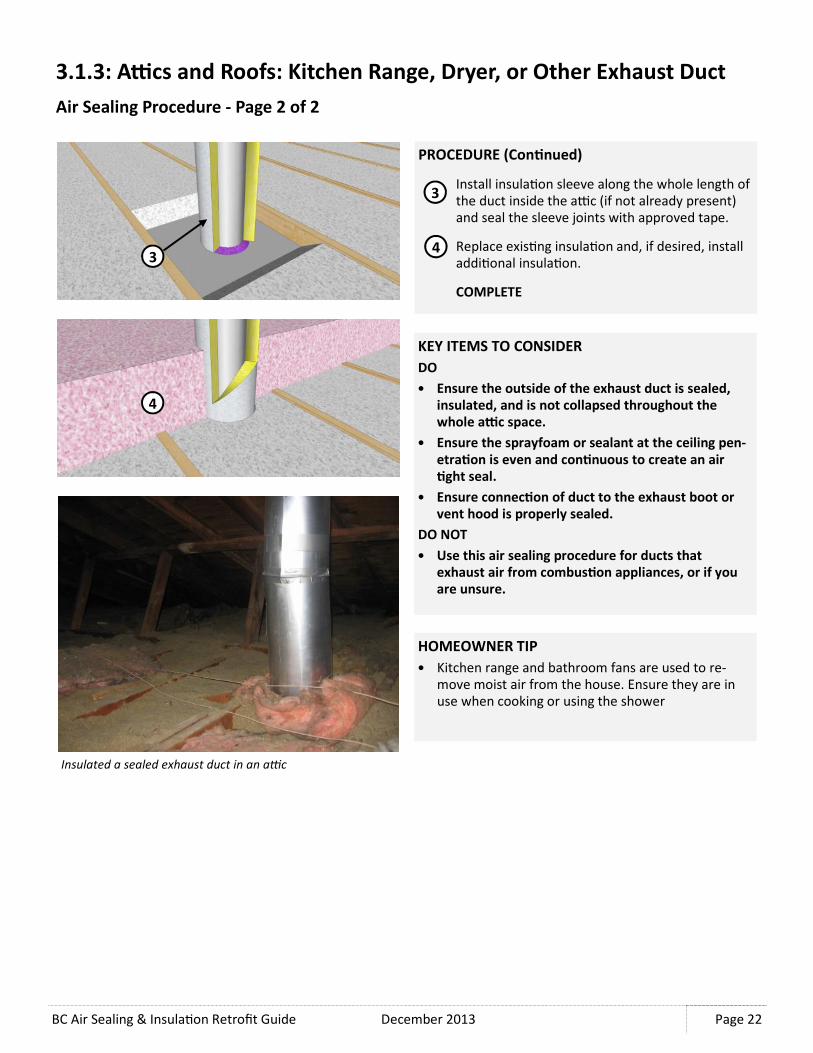
PROCEDURE (Con�nued)
Install insula�on sleeve along the whole length of
the duct inside the aDc (if not already present)
and seal the sleeve joints with approved tape.
Replace exis�ng insula�on and, if desired, install
addi�onal insula�on.
COMPLETE
3
3.1.3: A<cs and Roofs: Kitchen Range, Dryer, or Other Exhaust Duct
Air Sealing Procedure - Page 2 of 2
4
KEY ITEMS TO CONSIDER
DO
• Ensure the outside of the exhaust duct is sealed,
insulated, and is not collapsed throughout the
whole a<c space.
• Ensure the sprayfoam or sealant at the ceiling pen-
etra�on is even and con�nuous to create an air
�ght seal.
• Ensure connec�on of duct to the exhaust boot or
vent hood is properly sealed.
DO NOT
• Use this air sealing procedure for ducts that
exhaust air from combus�on appliances, or if you
are unsure.
3
4
HOMEOWNER TIP
• Kitchen range and bathroom fans are used to re-
move moist air from the house. Ensure they are in
use when cooking or using the shower
Insulated a sealed exhaust duct in an a�c

December 2013 BC Air Sealing & Insula�on Retrofit Guide
Page 23
3.1.4: A<cs and Roofs: Fireplace or Other Combus�on Appliance Vent
Air Sealing Procedure - Page 1 of 2
Gas fireplace or other hot exhaust metal chimney/vent penetra�ons are a
source of air leakage into aDcs. It is important to use only fire proof sealing
materials at loca�ons near to or in contact with the chimney. Fire resistant
silicone sealant is used where high temperatures are present. Do not place
insula�on or other building materials in contact with the metal chimney unless
approved to do so. Do not alter the configura�on of the metal chimney or
other related components without talking to a professional HVAC contractor.
This air sealing procedure is for metal exhaust vents that extend through the
ceiling into the aDc space. Side vented appliances are not addressed in this
guide as these penetrate through above grade walls.
MATERIALS NEEDED
• Fire resistant silicone sealant
• Sheet metal
• Circular metal duct (approx. 6” larger diameter than vent to be sealed)
RECOMMENDED TOOLS
• Caulking gun
• Sheet metal shears
PROCEDURE
Expose ceiling gypsum board and framing on each
side of the chimney chase.
Install sealant around joists and blocking to seal
the chase wall framing to the joist framing and at
the corners of the chase.
Install sealant along the top side of the joists and
blocking in order to adhere and seal the sheet
metal closure.
1
2
Metal chimney with sheet metal seal
over ceiling joists.
1
3
2
3

BC Air Sealing & Insula�on Retrofit Guide December 2013
Page 24
3.1.4: A<cs and Roofs: Fireplace or Other Combus�on Appliance Duct
Air Sealing Procedure - Page 2 of 2
PROCEDURE (Con�nued)
Cut and install the sheet metal closure to fit over
the chimney opening �ght to the metal chimney
with overlap at each joint. Apply sealant where
the metal closures lap and secure them together
as well as to the wood framing with screws.
Seal the metal closure to the chimney and at each
joint with silicone sealant.
Install an insula�on guard around chimney using
an oversized metal duct. Cut and fold tabs to
keep the insula�on guard spaced 3” from the
chimney on the top and boNom. Size it so that
the top edge is above the insula�on level,
including any addi�onal insula�on that may be
added.
Replace exis�ng insula�on and, if desired, install
addi�onal insula�on around the chimney
insula�on guard.
COMPLETE
4
5
6
7
KEY ITEMS TO CONSIDER
DO
• Ensure clearance between the chimney and all com-
bus�ble building materials is 3”, unless otherwise
instructed by an approved HVAC contractor
• Use only fireproof sealing material in contact with
the chimney where needed
DO NOT
• Insulate a hot exhaust flue. Any work done on a
chimney should only be done with direc�on from
an approved HVAC contractor.
• Cover the insula�on guard with insula�on or place
a<c insula�on in contact with the exhaust duct
HOMEOWNER TIPS
• If storage is planned in the aDc, ensure that no
items come in contact with the duct.
6
7
4
5

December 2013 BC Air Sealing & Insula�on Retrofit Guide
Page 25
3.1.5: A<cs and Roofs: Masonry Chimney
Air Sealing Procedure - Page 1 of 2
Fireplace masonry chimney penetra�ons are a major
source of air leakage into aDcs. It is important to use only
fire proof and non-combus�ble sealing materials within
3” of the chimney. Fire resistant silicone sealant is used
where high temperatures are present.
This air sealing procedure is for masonry chimneys that
extend through the ceiling into the aDc space.
MATERIALS NEEDED
• Fire resistant silicone sealant
• Sheet metal
• Gypsum board and wood framing
• Screws
RECOMMENDED TOOLS
• Caulking gun
• Sheet metal shears
• Drywall saw
• Drill or screw driver
PROCEDURE
Expose ceiling gypsum board approximately 12”
on all sides of the chimney.
Install silicone sealant around joists and blocking
to seal the ceiling gypsum board to the framing.
Install silicone sealant along the top side of the
joists and blocking in order to adhere and seal
the sheet metal closure.
1
2
Masonry chimney
2
1
3
3

BC Air Sealing & Insula�on Retrofit Guide December 2013
Page 26
3.1.5: A<cs and Roofs: Masonry Chimney
Air Sealing Procedure - Page 2 of 2
PROCEDURE (Con�nued)
Cut and install sheet metal closure to fit over the
chimney opening �ght to the masonry chimney
with overlap at each joint.
Seal metal closure to the chimney and at each
joint with silicone sealant. Sealant should be
applied between the metal closures prior to
installa�on of the second closure piece to ensure
con�nuity of the air barrier.
Install gypsum board insula�on guard around
joist framing. Allow 3” clear between the
insula�on guard and the masonry chimney. Size it
so that the top edge is above the insula�on,
including any addi�onal insula�on that may be
added.
Replace exis�ng insula�on and install addi�onal
insula�on around chimney insula�on guard.
COMPLETE
4
5
6
7
KEY ITEMS TO CONSIDER
DO
• Ensure clearance between the chimney and all
combus�ble building materials is 3”.
• Use fireproof sealing material when needed such as
when it is in contact with the chimney.
DO NOT
• Insulate the chimney. Any work done on a chimney
should only be done by an approved/cer�fied HVAC
contractor.
HOMEOWNER TIPS
• If storage is planned in the aDc, ensure no items
come in contact with the chimney.
6
7
4
5

December 2013 BC Air Sealing & Insula�on Retrofit Guide
Page 27
3.1.6: A<cs and Roofs: A<c Hatch
Air Sealing Procedure - Page 1 of 2
ADc hatches can oKen be overlooked for air sealing
work. They present a unique challenge because the hatch
has to be air �ght while s�ll allowing access to the aDc.
Air leakage occurs through the joint between the hatch
and the ceiling. The hatch is most oKen a piece of
gypsum board cut to size res�ng on a ledge made from
wood trim or the edge of the ceiling drywall inside the
opening.
This air sealing procedure is for hatches that rest on the
ceiling gypsum or wood trim ledge. In order to achieve an
effec�ve air seal it is important to check that the exis�ng
hatch is sized properly so that it has enough contact with
the opening ledge.
MATERIALS NEEDED
• Extruded polystyrene
• Self adhered weather stripping
• Plywood or OSB and framing lumber
• Screws
• Adhesive
RECOMMENDED TOOLS
• U�lity knife
• Wood saw
• Measuring tape
• Hammer and nails or drill and screws
PROCEDURE
Expose ceiling gypsum board approximately 12” on all
sides of the aDc access hatch.
Cut two pieces (or more) of rigid foam to adhere to
the access cover. Size the rigid foam so there is a layer
adhered to the access hatch that fits within the
opening joist space and there is a layer of foam that
fits overtop of the ceiling joists on all sides.
Adhere weather stripping to the ledge of the access
opening on all sides.
1
2
1
2
An a�c access hatch made from plywood res�ng on a wood
trimmed opening.
3
3

BC Air Sealing & Insula�on Retrofit Guide December 2013
Page 28
PROCEDURE (Con�nued)
Install plywood or OSB box around the opening.
Size the box so that the top edge is above the
addi�onal insula�on level. Notch it to fit around
joists and other framing and use addi�onal
framing to reinforce the box.
Replace exis�ng insula�on and, if desired, install
addi�onal insula�on around the box.
COMPLETE
4
3.1.6: A<cs and Roofs: A<c Hatch
Air Sealing Procedure - Page 2 of 2
5
KEY ITEMS TO CONSIDER
DO
• Ensure the a<c hatch is fully engaging the edge
gasket. If needed, install a latch or hooks on the
edge of the hatch to hold it firmly down
• Build the insula�on guard so that access to the
hatch is not impeded and it will remain intact with
con�nued passage into the a<c.
DO NOT
• Size the a<c hatch rigid insula�on to fit too closely
against the surrounding joist framing
• Place heavy items on the hatch to weigh it down
onto the gasket
HOMEOWNER TIP
• Be careful when entering the aDc. Use a flashlight/
headlamp or ensure there is enough light inside the
aDc to safely enter. Watch for obstruc�ons such as
overhead truss members or nails.
• Ensure the hatch is properly seated on the gasket
when closing the hatch.
4
5
OTHER NOTES
• If the aDc hatch has a built in aDc access ladder on the top side, addi�onal insula�on cannot be easily placed on
the hatch (step 2). The hatch can remain uninsulated, but aNen�on must be paid to the perimeter seals. Ensure
the aDc hatch sits �ghtly against the opening seals and keeps an air �ght seal when not in use
• Storage in the aDc is discouraged because of the risk of compressing the insula�on and reducing the insula�on
R-Value. If storage is planned, a plaZorm should be constructed above the insula�on to hold storage items
without compressing the insula�on.

December 2013 BC Air Sealing & Insula�on Retrofit Guide
Page 29
3.1.7: A<cs and Roofs: Wall Top Plate & Top Plate Penetra�ons
Air Sealing Procedure - Page 1 of 2
Top plates of interior (and exterior) walls are a common
point of air leakage. If the home has a polyethylene sheet
at the ceiling level that is not detailed as an air barrier, it
will allow air leakage at every loca�on where the ceiling
drywall terminates. In addi�on, even with a poly air
barrier at the ceiling, electrical, plumbing, and other
service penetra�ons in the top plates of interior walls are
oKen overlooked.
This air sealing procedure is for top plates without a
properly detailed air barrier at the ceiling plane. If a
polyethylene sheet is in place and runs between the two
top plates of the wall then this procedure is not required
though it may s�ll apply to service penetra�ons.
MATERIALS NEEDED
• Spray polyurethane sealant (spray can or 2-part froth pack)
• 10 mil polyethylene sheet or flexible gasket
• Acous�cal sealant
RECOMMENDED TOOLS
• U�lity knife
• Caulking gun
• Staple gun
PROCEDURE
Expose ceiling gypsum board approximately 12”
on both sides of the top plate. Clean area with
brush or vacuum to ensure adequate sealant
adhesion.
Install flexible gasket or polyethylene sheet
around larger penetra�ons such as plumbing
stacks. Seal it with acous�cal sealant, staple it to
the ceiling, and clamp it to the vent stack with a
pipe clamp. This flexible air seal is to
accommodate thermal movement of the plas�c
vent pipe.
Install sealant around smaller penetra�ons such
as electrical wires.
1 1
2
Exposed interior top plate as viewed from the a�c.
2

BC Air Sealing & Insula�on Retrofit Guide December 2013
Page 30
PROCEDURE (Con�nued)
Install sprayfoam over the top plate joints and
penetra�ons where needed to seal the ceiling to
the top plate.
Replace exis�ng insula�on and, if desired, install
addi�onal insula�on.
COMPLETE
3
3.1.7: A<cs and Roofs: Wall Top Plate & Top Plate Penetra�ons
Air Sealing Procedure - Page 2 of 2
4
KEY ITEMS TO CONSIDER
DO
• Use a flexible air seal like a polyethylene sheet or
rubber gasket where movement is expected.
• Seal all penetra�ons with sprayfoam where no
movement is expected. Ensure all surfaces are
clean to achieve sealant adhesion
• Use a fire rated silicone sealant if sealing electrical
boxes within the a<c space.
DO NOT
• Use sprayfoam directly in contact with electrical
fixtures or uninsulated wires.
HOMEOWNER TIP
• If performing renova�ons where new wiring or
plumbing stacks are added through the ceiling,
ensure a similar procedure is followed for air sealing.
3
4

December 2013 BC Air Sealing & Insula�on Retrofit Guide
Page 31
3.1.8: A<cs and Roofs: Large Openings, ShaFs, or Drop Ceilings
Air Sealing Procedure - Page 1 of 2
Large openings in the ceiling plane where service shaKs
or drop ceilings occur can be a major air leakage path in
to aDcs.
This air sealing procedure is for openings in the ceiling
plane running perpendicular to the ceiling joists. Where
the opening runs parallel, a similar procedure can be
used with some adjustments.
MATERIALS NEEDED
• Spray polyurethane sealant (spray can or 2-part froth pack)
• Wood, OSB or gypsum board
• Wood or drywall screws
• Polyurethane sealant
RECOMMENDED TOOLS
• Wood or drywall saw
• Vacuum or small broom
PROCEDURE
Expose ceiling gypsum board approximately 12”
on all sides of the ceiling opening. Clean area to
ensure adequate sealant adhesion.
Install wood or gypsum board cover between
joists. Screw it down to the top plate or adhere
with sealant.
1 1
2
A rela�vely large hole in the ceiling plane through which
two ducts are installed
2

BC Air Sealing & Insula�on Retrofit Guide December 2013
Page 32
PROCEDURE (Con�nued)
Install sprayfoam over the edges of the cover to
seal it to surrounding joists and ceiling gypsum
board. Seal along the ends of the drop ceiling on
either side of the ceiling joist with sprayfoam.
Replace exis�ng insula�on and, if desired, install
addi�onal insula�on.
COMPLETE
3
3.1.8: A<cs and Roofs: Large Openings, ShaFs, or Drop Ceilings
Air Sealing Procedure - Page 2 of 2
4
KEY ITEMS TO CONSIDER
DO
• Be careful around the openings of shaFs and drop
ceilings. Only use the joists and raFers to move
around on. Do not step on the ceiling.
• Thoroughly seal around the opening cover and all
adjacent framing.
DO NOT
• Use thin or flimsy material for the cover like card-
board or plas�c. The material must be able to sup-
port addi�onal insula�on and remain air�ght.
HOMEOWNER TIP
• Do not store items in the aDc on top of the finished
cover. Use an aDc stand off plaZorm to keep the
storage items above the level of the new insula�on.
3
4

December 2013 BC Air Sealing & Insula�on Retrofit Guide
Page 33
3.1.9: A<cs and Roofs: A<c Knee Walls
Air Sealing & Insula�ng Procedure - Page 1 of 2
Knee walls which divide interior space from aDc space
should be treated like exterior walls in how they are air
sealed (and insulated). Knee walls are oKen built directly
over upper floor framing, allowing aDc/floor joists to run
con�nuously underneath. This allows air leakage under
the knee wall boNom plate within every joist space.
This air sealing and insula�on procedure is for a knee wall
that runs perpendicular to the floor joist framing, and an
aDc space with or without exis�ng floor boards.
MATERIALS NEEDED
• Spray polyurethane sealant (2-part froth pack)
• Fibreglass or mineral wool baN insula�on or
• XPS foam board
• Rigid fibreglass or mineral wool insula�on boards
RECOMMENDED TOOLS
• U�lity knife
PROCEDURE
Remove knee wall insula�on (if present) and
expose ceiling gypsum board and framing at the
knee wall interface.
Note: Cut back any exis�ng a�c floor boards as
necessary to expose under the boEom plate of the
knee wall framing.
Roll baN insula�on into the joist space under the
knee wall as backer for sprayfoam.
Alterna�vely, install rigid foam board under the
knee wall in each joist space as a backer for the
sprayfoam.
1
2
Knee wall framing.
1
2

BC Air Sealing & Insula�on Retrofit Guide December 2013
Page 34
PROCEDURE (Con�nued)
Install sprayfoam over the ceiling joist to knee
wall interface to create an air seal.
Note: Wall penetra�ons should be sealed to the
gypsum board making this the air�ght element.
See wall air sealing measures in Sec�on 3.5.
Replace the aDc insula�on and re-fluff the knee
wall insula�on where present or install new baN
insula�on.
Install addi�onal rigid fiberglass or mineral wool
insula�on boards at the knee wall. Addi�onal
rigid wall insula�on will contain the baN
insula�on and increase the R-value of the wall.
If desired, install addi�onal aDc ceiling insula�on.
COMPLETE
3
3.1.9: A<cs and Roofs: A<c Knee Walls
Air Sealing & Insula�ng Procedure - Page 2 of 2
4
5
KEY ITEMS TO CONSIDER
DO
• Remove any floor boards or subfloor in the a<c
space (if present) to exposed the joists running un-
der the knee wall.
• Seal under the boGom plate of the knee wall along
the whole length at each floor joist.
DO NOT
• Use rigid foam as addi�onal insula�on, as rigid min-
eral wool or fibreglass boards are preferred in this
applica�on (cold side of the knee wall insula�on) to
avoid a poten�al vapour diffusion issue.
HOMEOWNER TIP
• If there is an access door to the aDc space in the
wall of the upper floor, make sure it is sealed with
exterior door weather-stripping.
6
3
4
5
6

December 2013 BC Air Sealing & Insula�on Retrofit Guide
Page 35
3.1.10: A<cs and Roofs: Adding Insula�on
Adding Insula�on - Page 1 of 3
Adding insula�on to the aDc space is oKen a very
effec�ve energy saving measure. Insula�on should
only be added aKer and in conjunc�on with air
sealing procedures as described in the previous
sec�ons. It is important to choose the most
appropriate insula�on type for the aDc, insulate
to achieve adequate effec�ve R-values, and
ensure adequate aDc ven�la�on is provided.
Insula�on Type
If the aDc is obstructed and an irregular shape,
blown in fibreglass or cellulose may be the best
op�on, as the loose fill can fill around obstruc�ons
and provide a con�nuous blanket of insula�on.
Blown-in insula�on can also be combined with
baN insula�on if desired, with the loose fill above
the baN insula�on. Ensure that no insula�on gets blown into the soffit vent area or in contact with heat genera�ng
fixtures or chimneys. See Sec�on 3.1.1—3.1.9 for air sealing procedures that allow for insula�on guards. If the aDc is
a simple shape with joists spaced regularly at 16” or 24”, fibreglass or mineral wool baN insula�on may by a good
op�on as it is can be easy to install. Be sure to install the insula�on with a snug fit but without compressing the
insula�on. In general, be sure to follow the manufacturers direc�ons when installing all types of insula�on to achieve
op�mal results. Both blown-in and baN insula�on can be combined with sprayfoam in the aDc space in a Flash and
Fill applica�on. See Sec�on 3.1.11 for Flash and Fill procedures. Addi�onal informa�on about insula�on can be found
from product manufacturers and within Insula�on: A Guide for Contractors to Share with Homeowners (2012).
Insula�on Thickness
Blown or baN fibrous insula�on installed on the ceiling of an aDc will typically have an installed R-value of between R-
3 to R-4 per inch of thickness depending on the type, manufacturer, and density. See product manufacturers’
published data for specific product informa�on. To reach the desired R-value (typically within the range of R-40 to R-
60), the insula�on should be installed to the desired thickness per the table below. Note that the insula�on thickness
will be reduced at the eaves due to the slope of the roof sheathing and this will reduce the effec�ve R-value of the
ceiling plane. This can typically be made up by adding a few extra inches of insula�on in the center, unless the roof
slope is par�cularly shallow. If desired, guidance on the reduc�on calcula�on can be found within the Guide for
Designing Energy Efficient Building Enclosures published by FP Innova�ons.
Blown-in fiberglass a�c insula�on
Insula�on
R-value/inch 12 inches 14 inches 16 inches 18 inches 20 inches
3.0 36.0 42.0 48.0 54.0 60.0
3.2 38.4 44.8 51.2 57.6 64.0
3.4 40.8 47.6 54.4 61.2 68.0
3.6 43.2 50.4 57.6 64.8 72.0
3.8 45.6 53.2 60.8 68.4 76.0
4.0 48.0 56.0 64.0 72.0 80.0
Insula�on Thickness

BC Air Sealing & Insula�on Retrofit Guide December 2013
Page 36
3.1.10 A<cs and Roofs: Adding Insula�on
Adding Insula�on - Page 2 of 3
A<c Ven�la�on
ADc spaces in most older homes in BC will oKen have been originally designed as a ven�lated space. If the aDc is not
vented and has not been insulated at the roof plane, then it is possible that the original aDc vents were at some point
blocked off incidentally during re-roofing (e.g. cedar shingle/shake to asphalt shingle conversion) or other home
renova�ons. ADc ven�la�on is an important factor in controlling moisture within the aDc, reducing heat build-up in
summer, and reducing ice damming in snowy climates. Poor aDc ven�la�on coupled with the leakage of indoor air
into the aDc causes most aDc moisture and mould problems in BC.
For aDc ven�la�on to be most effec�ve, outdoor air should enter the aDc low at the aDc perimeter (i.e. at the
soffits) and exit high near the aDc ridge (i.e. ridge vents or cap vents installed near ridge). The soffit vents can be
provided in the form of perforated soffit material, discrete vents within the soffit material, or if no soffit is present
then buNon vents installed near the soffit. If there is a gable end wall, then vents may also be placed near the boNom
of these walls above the insula�on level. Soffit vents must connect through to the aDc and past the insula�on,
typically by the use of insula�on baffles or guards. Typically these are placed between trusses at every bay or every
second bay depending on the roof configura�on and available soffit area for ven�ng.
The area and size of the aDc vents can be determined by the current 2012 BC Building Code which requires that
aDcs are vented with a net free vent area of 1:300. This means that for every 300 square feet of ceiling area, 1 square
foot of vent is required. Ideally this vent area is split evenly
between the soffit and ridge, though the code does allow for
up to 75%/25% of the vent area to be distributed at either the
top or the boNom. While this is allowed by code, it is
generally accepted beNer prac�ce to evenly distribute the
vents between the soffit area and ridge. If it is not possible to
balance the ven�ng arrangement, then it is best to install
more of the vents at the soffit rather than the ridge to reduce
nega�ve aDc pressures within the aDc as a result of wind.
While the 1:300 rule is a minimum code requirement, it
should also not be exceeded by a large margin. Providing too
much ven�la�on can cause moisture problems in coastal
climates.
AKer air sealing measures have been performed, the amount
of air leakage into the aDc should be substan�ally reduced. In
addi�on, the vapour barrier at the ceiling plane (painted
ceiling finish, kraK-faced baNs or polyethylene) will limit the
amount of vapour diffusion into the space. ADc ven�la�on may s�ll be beneficial even if the original aDc was not
ven�lated. Therefore if vents are not provided, then they should be added as part of the insula�on retrofit. When
aDc vents are installed through the roofing material, a roofing contractor should be hired to properly install, shingle,
and seal the vent within the exis�ng roofing. It is common to see an aDc vent cause a roof leak due to a poor
installa�on. Holes cut through roofing are best installed at the �me of re-roofing; however, this does not always
coincide with weatheriza�on work.
Insula�on baffles being installed at every second truss bay
as part of an insula�on retrofit to provide opening from
soffit vents into the a�c space past the insula�on (to be
blown in aIer)

December 2013 BC Air Sealing & Insula�on Retrofit Guide
Page 37
PROCEDURE
Remove exis�ng insula�on and air seal the aDc
(see previous)
Install insula�on baffles as required along the
roof edge or above each soffit ven�la�on port if it
is not a con�nuous soffit vent.
Install baN insula�on into every empty joist space
to block new blown aDc insula�on from entering
the vent space later.
Replace exis�ng aDc insula�on (if present).
Install addi�onal aDc ceiling insula�on per the
manufacturer’s instruc�ons. See previous page
for guidance on the appropriate insula�on type,
and appendices for guidance on the amount of
insula�on needed.
COMPLETE
3.1.10 A<cs and Roofs: Topping Up Exis�ng Insula�on
Adding Insula�on - Page 3 of 3
KEY ITEMS TO CONSIDER
DO
• Ensure all roof/a<c ven�la�on openings are clear
of insula�on and debris
• Install the insula�on to achieve a con�nuous, non-
compressed blanket of insula�on.
DO NOT
• Let insula�on contact non IC rated light fixtures or
contact hot duct work or chimneys. See Sec�on
3.1.1, 3.1.4, and 3.1.5 for details.
HOMEOWNER TIP
• Once new insula�on is installed the aDc floor should
not be used for storage unless an elevated plaZorm
is constructed above the insula�on. Any compressed
insula�on should be re-fluffed to the original depth if
the aDc floor is walked on.
3
5
MATERIALS NEEDED
• Blown in or baN aDc insula�on
• Preformed insula�on baffles
RECOMMENDED TOOLS
• U�lity knife
• Staple gun or glue
• Insula�on blowing system (if needed)
1
2 3
4
1
2
3
4
5
5
Blown-in insula�on prior to installa�on and blowing machine

BC Air Sealing & Insula�on Retrofit Guide December 2013
Page 38
3.1.11 A<cs and Roofs: Flash and Fill Insula�on
Air Sealing & Insula�ng Procedure - Page 1 of 1
The goal of Flash and Fill applica�on in the aDc is to
simplify the air sealing process in the aDc, where there
may be many air leakage paths into the aDc by achieving
a single air �ght layer at the ceiling before insula�on is
installed. It is important to review the previous air
sealing procedures if there are non-IC rated pot lights,
service penetra�ons subject to movement, and chimneys
within the aDc. Flash and Fill is especially efficient if the
celling is a material with many gaps like wood panelling
or tongue and groove boards. In addi�on to air sealing
the aDc, closed cell sprayfoam can provide a con�nuous
vapour barrier at the ceiling plane, further reducing
moisture entering the aDc from the living space.
This procedure is for the Flash and Fill applica�on within
an accessible aDc.
MATERIALS NEEDED
• Spray Polyurethane Foam
(Large amounts required, use of sprayfoam
insula�on contractor recommended)
• Preformed insula�on baffles
• Blown-in or baN aDc insula�on
RECOMMENDED TOOLS
• U�lity knife
• Staple gun or glue
• Insula�on blowing system (if needed)
Flash and fill a�c installa�on where a few inches of
sprayfoam is sprayed to top of ceiling drywall, and then cov-
ered with lower cost low-density cellulose or fiberglass insu-
la�on fill
KEY ITEMS TO CONSIDER
DO
• Ensure contractor is trained in this applica�on
• Ensure all correct air sealing measures have been
taken around heat genera�ng fixtures and other
service penetra�ons prior to flash coat.
DO NOT
• Apply a layer of closed-cell sprayfoam greater than
2” thick or into a concealed void. Follow all manu-
facturers instruc�ons when using sprayfoam.
6 4
PROCEDURE
Remove all the exis�ng aDc insula�on and
thoroughly clean the aDc floor.
Install insula�on baffles as required along the
roof edge or above each aDc ven�la�on port if it
is not a con�nuous soffit vent.
Install baN insula�on into every empty joist space
to block new blown aDc insula�on from entering
the vent space later.
Cover non IC/AT rated recessed lights and other
electrical fixtures in the aDc with boxes as need
to make an air �ght seal and to avoid contact
with insula�on. Follow aDc air sealing
procedures in Sec�ons 3.1.1 — 3.1.9 as necessary
to fill large holes prior to flash coat. Failure to do
so can result in sprayfoam in undesirable
loca�ons or damage to exis�ng components.
Flash coat the en�re aDc floor with a coat of
sprayfoam to create a con�nuous air seal.
Install new aDc ceiling insula�on. (See previous)
COMPLETE
2 3
1
1
2
3
4
5
6
5

December 2013 BC Air Sealing & Insula�on Retrofit Guide
Page 39
3.1.12 A<cs and Roofs: Vaulted and Flat Roofs, Inaccessible A<cs
Air Sealing - Page 1 of 1
Air sealing a vaulted ceiling below ceiling joists with no
aDc space is most feasible from the interior side. If no
major ceiling removal work is planned then the best way
is to seal all penetra�ons in the ceiling finish with
appropriate sealants. A gypsum board ceiling is a good air
barrier material for the field of the ceiling, so sealing the
penetra�ons is important to make most of the ceiling
air�ght.
These air sealing loca�ons are for vaulted ceilings,
ceilings below flat roofs, or ceilings that do not have an
accessible aDc space above them.
Wood boards as the ceiling finish and recessed light fixtures.
TYPICAL AIR SEALING LOCATIONS
Tops of par��on and exterior walls at the ceiling
sealed with paintable polyurethane sealant.
Support structures like beams and columns
sealed with paintable polyurethane sealant.
Skylight frames sealed with polyurethane sealant.
Electrical receptacles, light fixtures, and other
ceiling fixtures sealed behind the trim plates with
acous�cal sealant (to prevent permanent
adhesion).
2 1
5
4
3
Exhaust vents and chimney openings sealed with
fire resistant silicone sealant. Fire resistant
silicone sealant used at all hot and combus�on air
exhaust vents and chimney penetra�ons. 1
2
3
4
5
4

BC Air Sealing & Insula�on Retrofit Guide December 2013
Page 40
3.1.13 A<cs and Roofs: Vaulted Ceilings and Inaccessible A<cs
Interior vs. Exterior Insula�on
The building enclosure can be retrofiNed from either the
exterior or the interior, each with advantages and
disadvantages. Which method is most appropriate for a
given applica�on depends on the house’s interior and
exterior finishes, layout and construc�on, lot line setback
requirements, other renova�on needs, and whether the
house will be occupied during the work. For example, if
the cladding is being replaced as part of previously
planned renova�ons, an air sealing and insula�on
program applied from the exterior is likely most
appropriate. Whereas, interior renova�ons may more
easily facilitate retrofit work from the interior.
An important advantage of interior retrofits is that they
can typically be carried out year-round as the cladding and
weather resis�ve barriers are not impacted by the work.
Addi�onally, this type of retrofit may be necessary if
property line setbacks do not permit for increasing the
thickness of the enclosure on the exterior. For vaulted
ceilings or inaccessible aDcs, insula�ng from the interior
is best suited for spaces where interior remodeling is
already taking place, and head room is not limited. Since
exis�ng roof joists are not usually deeper than 8 to 10
inches, adding rigid insula�on to the underside of the
joists to increase the R-value of the roof should be
considered. Adding insula�on below the joists will lower
the level of the exis�ng ceiling finish and poten�ally
impact headroom. Insula�ng from the interior also
presents the opportunity to inspect the exis�ng elements
of the roof for decay or damage. As with all assemblies
where insula�on is added on the interior, par�cular
aNen�on must be paid to the air barrier and vapour
retarder as increased insula�on levels can decrease sheathing and framing temperatures consequently increasing the
risk of condensa�on and associated moisture damage.
An exterior retrofit can be most appropriate when interior floor area is limited, when exterior renova�on work is
planned, and to limit disturbance to house occupants. This method also provides an opportunity to detect and repair
water entry problems. Air sealing and installa�on of insula�on on the exterior of a house also has a number of
technical advantages. It is oKen easier to avoid large thermal bridges such as studs and joists in exterior insula�on
which makes the insula�on more effec�ve, and air sealing from the exterior is oKen simpler as there are less
penetra�ons to accommodate. Addi�onally, exterior insula�on increases the temperature of sheathing and framing
which reduces the poten�al for condensa�on and associated damage. Insula�ng the roof/aDc from the exterior is
most applicable when the exis�ng roof is too shallow to accommodate target insula�on levels or when other work on
the roof is already planned.
The following sec�ons cover two conceptual roof insula�on retrofits for an exis�ng wood frame home using either an
interior or exterior insula�on approach. Many industry references provide addi�onal informa�on and details for this
type of more extensive work.
Interior and exterior insula�ng strategies as part of retrofi�ng
procedures for the whole house.

December 2013 BC Air Sealing & Insula�on Retrofit Guide
Page 41
3.1.14 A<cs and Roofs: Vaulted Ceilings and Inaccessible A<cs
Interior Insula�on - Conceptual - Page 1 of 1
Insula�ng a vaulted ceiling from the interior requires removal of the interior finish. The joist space must be accessed
to ensure adequate ven�la�on against the underside of the exis�ng sheathing. Blown cellulose or fiberglass insula�on
should not be installed blind from the inside into vaulted ceilings or flat roofs. Ven�la�on is required to inhibit
condensa�on and allow the wood structure to dry and is par�cularly important in a retrofit applica�on. Since the
ceiling finish must be removed anyway, it is advisable to add interior insula�on to increase the R-Value of the roof
assembly; however, this is not required. Addi�onal insula�on can be installed on the underside of the exis�ng roof
joists, or extra framing can be added to increase the roof joist depth.
Moisture Control for Dense-Packed Roof Assemblies in Cold Climates: Final Measure Guideline by Building Science
Corpora�on is a good source of further guidance regarding interior insula�on of vaulted ceilings.
DESIGN CONSIDERATIONS
Exis�ng interior finish and insula�on (if any) to be
removed. Exis�ng roof sheathing exposed. Fram-
ing and sheathing inspected and repaired as
needed.
Vent space against the underside of the sheath-
ing made with vapour permeable baffles such as
1/4” plywood or perforated baffles.
BaN insula�on to the depth of the roof joist
against the baffles.
2 1
5 4
3
Rigid foam insula�on against the underside of the
roof joists. Joints taped to ensure air �ghtness.
Insula�on fastened to the underside of the roof
joists with wood strapping.
Op�on: Gypsum board with gaskets to create air
�ght drywall. If no rigid foam is installed or if rigid
mineral wool is use in place of rigid foam, a
vapour barrier must be installed at interior side of
the insula�on, such as polyethylene or vapour
retarder paint on drywall.
Interior finish.
1
2
3
4
5
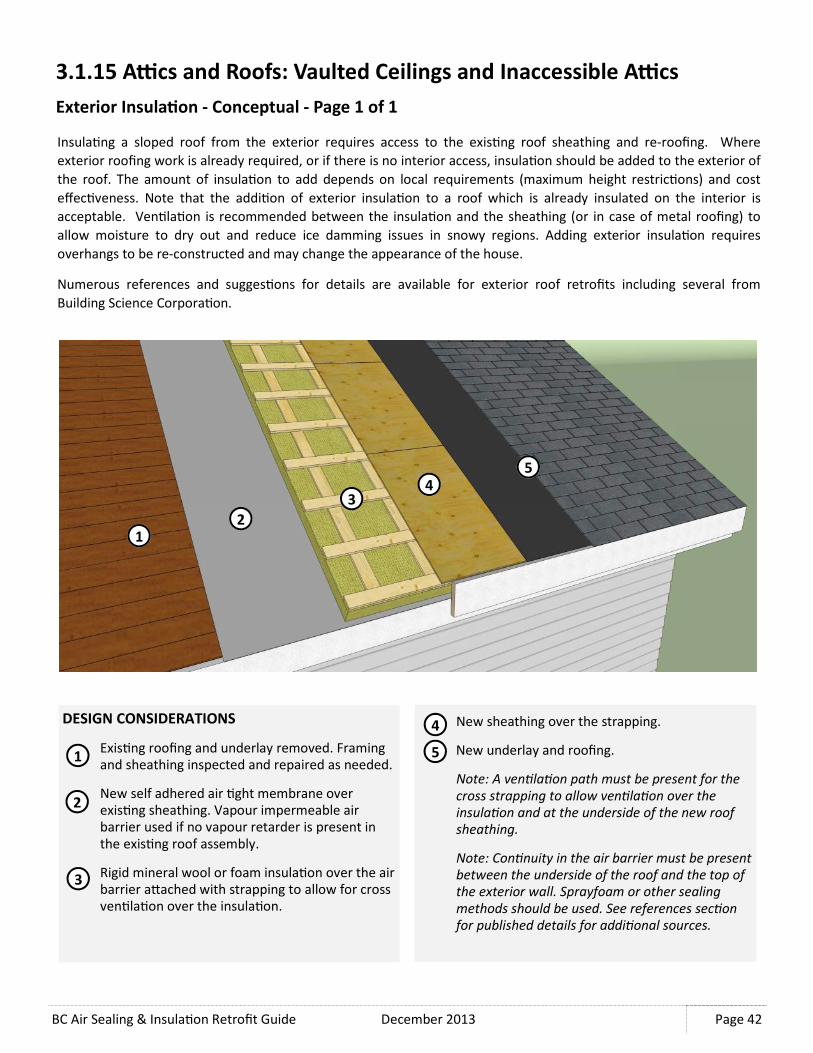
BC Air Sealing & Insula�on Retrofit Guide December 2013
Page 42
3.1.15 A<cs and Roofs: Vaulted Ceilings and Inaccessible A<cs
Exterior Insula�on - Conceptual - Page 1 of 1
Insula�ng a sloped roof from the exterior requires access to the exis�ng roof sheathing and re-roofing. Where
exterior roofing work is already required, or if there is no interior access, insula�on should be added to the exterior of
the roof. The amount of insula�on to add depends on local requirements (maximum height restric�ons) and cost
effec�veness. Note that the addi�on of exterior insula�on to a roof which is already insulated on the interior is
acceptable. Ven�la�on is recommended between the insula�on and the sheathing (or in case of metal roofing) to
allow moisture to dry out and reduce ice damming issues in snowy regions. Adding exterior insula�on requires
overhangs to be re-constructed and may change the appearance of the house.
Numerous references and sugges�ons for details are available for exterior roof retrofits including several from
Building Science Corpora�on.
DESIGN CONSIDERATIONS
Exis�ng roofing and underlay removed. Framing
and sheathing inspected and repaired as needed.
New self adhered air �ght membrane over
exis�ng sheathing. Vapour impermeable air
barrier used if no vapour retarder is present in
the exis�ng roof assembly.
Rigid mineral wool or foam insula�on over the air
barrier aNached with strapping to allow for cross
ven�la�on over the insula�on.
2 1
5 4
3
New sheathing over the strapping.
New underlay and roofing.
Note: A ven�la�on path must be present for the
cross strapping to allow ven�la�on over the
insula�on and at the underside of the new roof
sheathing.
Note: Con�nuity in the air barrier must be present
between the underside of the roof and the top of
the exterior wall. Sprayfoam or other sealing
methods should be used. See references sec�on
for published details for addi�onal sources.
1
2
3
4
5

December 2013 BC Air Sealing & Insula�on Retrofit Guide
Page 43
3.2.1 Below Grade Walls: Basement Wall Interior
Air Sealing- Page 1 of 1
Air sealing at the basement level is important to the whole house air�ghtness. Air sealing measures at below grade
walls is possible only from the inside, unless work is planned to expose the founda�on wall from the outside.
There are typically many unsealed and exposed penetra�ons in an unfinished or par�ally finished basement. If
finishing work is planned in conjunc�on with air sealing measures, see Sec�on 3.2.3 for interior insula�on measures
as well. The main focus of air sealing should be the at the rim joist around the perimeter of the basement.
TYPICAL AIR SEALING LOCATIONS
Penetra�ons in any wood frame walls above
basement pony walls, including any
discon�nui�es in the poly sheet sealed using
acous�cal sealant and sheathing tape (at
polyethylene joints).
Cracks in the founda�on sealed with
polyurethane sealant.
Floor joists at the rim joist sealed with foam
board and sprayfoam (see Sec�on 3.2.2).
2
1
5
4
3
Polyurethane sealant between the founda�on
wall and basement slab to seal gaps between the
concrete slab and wall.
Service penetra�ons in the basement founda�on
wall sealed with sprayfoam, polyurethane, or
silicone sealant.
Note: If founda�on cracks or penetra�ons are
leaking water from the exterior, a founda�on
water proofing contractor should be retained.
4
5
1
2
3
4
5

BC Air Sealing & Insula�on Retrofit Guide December 2013
Page 44
3.2.2 Below Grade Walls: Basement Wall
Interior vs. Exterior Insula�on Placement
Below grade walls should be insulated and air sealed as part of the
energy efficiency measures for the whole house. An insulated
basement can reduce energy consump�on and associated costs, and
create a more comfortable living space.
Insula�ng below grade walls from the interior is best suited for
basements where interior finishing or re-finishing is planned and can
provide an economical approach as compared to exterior insula�on
methods which require excava�on around the founda�on walls. Rigid
foam insula�on boards or sprayfoam can be installed on the interior
side of the founda�on wall. As with all interior insula�on methods, it
is important to maintaining air�ghtness to prevent rela�vely warm
moist interior air from contac�ng the concrete founda�on wall as this
can pose a significant condensa�on risk.
Insula�ng founda�on walls from the exterior oKen provides the best
performance; however, can be cost prohibi�ve unless installed in
conjunc�on with other exterior founda�on work such as installa�on
of perimeter drainage or damp proofing. However, if excava�on of
the wall is conducted for other work, installa�on of exterior insula�on
is straighZorward. This method of insula�ng the founda�on wall is
most effec�ve when used in conjunc�on with exterior insula�on on
the above grade walls as it greatly simplifies transi�on detailing and
limits the poten�al for thermal bridging. As with other types of
assemblies, exterior insula�on on below grade walls increases the
temperature of the founda�on wall and reduces the poten�al for
condensa�on on the interior.
Basement slabs are generally air �ght unless large cracks or holes are
present, but it is recommended that the slab be insulated with rigid
foam and finished. Many of the considera�ons for floor slab insula�on
are similar to those for insula�on of the below grade walls; however,
the floor slab insula�ng procedure is not included in this guide.
The following two sec�ons cover two conceptual below grade wall
insula�on retrofits for an exis�ng home on a concrete founda�on
using either an interior or exterior insula�on approach.
Interior and exterior below grade insula�ng
strategies as part of retrofi�ng procedures for
the whole house.

December 2013 BC Air Sealing & Insula�on Retrofit Guide
Page 45
3.2.3 Below Grade Walls: Basement Wall
Interior Insula�ng Procedure - Page 1 of 2
Insula�ng the interior of the basement walls prior to
finishing is an effec�ve way to increase the thermal
performance and air �ghtness of the house. The
basement is prone to excessive air infiltra�on due to
stack effect, which can create nega�ve pressures at the
basement, drawing in cold air from the ground and
outside. Prior to insula�on, air sealing must be done on
any large openings and around service penetra�ons. If
founda�on cracks or penetra�ons are leaking water
from the exterior, a founda�on water proofing
contractor should be retained.
This insula�ng procedure is for below grade founda�on
walls that will be receiving an interior finish. If the
basement is not going to be used but is s�ll accessible,
this procedure should be altered to avoid the use of
foamed plas�cs in loca�ons where the will not be
covered with finishes.
MATERIALS NEEDED
• Rigid XPS foam board insula�on.
• Spray polyurethane sealant (2-part froth pack)
• Sheathing tape and sealant
• Wood framing and gypsum board
RECOMMENDED TOOLS
• U�lity knife
• Insula�on aNachment system or glue
• Tools for framing and drywall finishing
PROCEDURE
Expose the basement founda�on wall and floor
joists. If required, remove exis�ng finishes and
cut back the ceiling finish at the edge to expose
the rim joist.
Install rigid foam insula�on on the basement
walls per manufacturer’s instruc�ons.
Tape the joints of the insula�on with sheathing
tape and seal the boNom edge of the insula�on
to the basement floor slab.
1
2
Exposed below grade wall at floor rim joist.
1
2 3
3

BC Air Sealing & Insula�on Retrofit Guide December 2013
Page 46
PROCEDURE (Con�nued)
Expose and clean the rim joist and floor joists.
Remove exis�ng insula�on (if present).
Install rigid insula�on into each joist space. Size
each piece to fit snugly in the joist space and cut
around penetra�ons. Use mul�ple layers to
achieve the desired insula�on value.
Install sprayfoam around the perimeter of the rim
joist insula�on, sealing it to the subfloor above,
floor joists, and wall insula�on.
Install or reinstall the ceiling finish. Install wood
furring and drywall finish on the founda�on walls.
Rigid foam board can not be leK exposed within
living spaces.
COMPLETE
4
3.2.3 Below Grade Walls: Basement Wall
Interior Insula�ng Procedure - Page 2 of 2
5
6
KEY ITEMS TO CONSIDER
DO
• Ensure an air �ght assembly is used in conjunc�on
with installing insula�on. Special aGen�on should
be paid to air sealing the rim joists.
• Spray polyurethane foam insula�on could be used
as an alternate to the XPS board insula�on
DO NOT
• Leave the rigid foam exposed in the basement.
Refer to the building code for guidance on exposed
foamed plas�cs. Typically a layer of gypsum board
is sufficient to cover the foam.
• Install fiberglass insula�on against the concrete
wall. Fiberglass is not recommended in this
applica�on.
HOMEOWNER TIP
• Regularly inspect the perimeter of the basement
floor at the founda�on wall to make sure there are
no leaks or condensa�on entering the living area.
4
6
7 5
7

December 2013 BC Air Sealing & Insula�on Retrofit Guide
Page 47
3.2.4 Below Grade Walls: Basement Wall
Exterior Insula�ng Procedure - Page 1 of 2
Insula�on on the exterior of the founda�on wall can be the easiest way to increase the thermal performance of the
below grade walls, providing exterior founda�on work is already taking place. In most cases, the concrete wall will act
as the air barrier, but cracks and penetra�ons must s�ll be sealed. The founda�on damp proofing must be con�nuous
in order to create an effec�ve air barrier. If exterior siding work is also taking place, the wall air barrier can be �ed
into the founda�on air barrier, simplifying the air sealing procedure at the rim joist. If siding work is not planned, care
must be taken to ensure the new materials properly �e in to the exis�ng above grade wall with posi�ve laps. Air
sealing at the rim joist is likely s�ll needed in this case.
This insula�ng procedure is for below grade walls that will be backfilled and exposed at the top edge.
MATERIALS NEEDED
• Rigid foam board insula�on
• Rigid foam board insula�on with concrete coa�ng
• Drain mat
• Flashing and nails
• Wall membrane materials (if required)
RECOMMENDED TOOLS
• U�lity knife
• Insula�on aNachment system
• Sheet metal sheers
• Hammer
PROCEDURE (NO SIDING WORK)
Ensure there is a con�nuous coa�ng of
founda�on damp proofing membrane.
Install rigid foam board in the field of the
founda�on wall. ANach with insula�on pins as
required to temporarily hold the insula�on to the
wall.
Install insula�on board with concrete coa�ng
where the founda�on wall will be exposed above
grade.
Install flashing over the top edge of the insula�on
board and properly lapped behind the exis�ng
cladding and sheathing membrane.
Install drain mat over the insula�on.
Back fill as required.
COMPLETE
1
2
1 2
3 5
4
5
3
4 6
6

BC Air Sealing & Insula�on Retrofit Guide December 2013
Page 48
PROCEDURE (WITH SIDING WORK)
Ensure there is a con�nuous coa�ng of
founda�on damp proofing membrane.
Install a strip of self adhered membrane over the
rim joist and sill plate, and on to the founda�on
wall.
Install rigid foam board in the field of the
founda�on wall. ANach with insula�on pins as
required to hold the insula�on to the wall.
Install insula�on board with concrete topping.
Install drain mat and back fill as required.
Install flashing over the insula�on board. Tape
the top edge of the flashing to the self adhered
membrane strip.
Install the air �ght sheathing membrane over the
wall. Tape the boNom edge to the flashing and
install siding as required.
COMPLETE
1
3.2.4 Below Grade Walls: Basement Wall
Exterior Insula�ng Procedure - Page 2 of 2
2
3
KEY ITEMS TO CONSIDER
DO
• Ensure there is a con�nuous air barrier at
penetra�ons and cracks in the founda�on wall.
Repair leaky holes as needed prior to installing
insula�on.
• Ensure the top edge of the flashing above the
insula�on is properly �ed in to the exis�ng wall
above.
DO NOT
• Insulate over the founda�on foo�ng or drain �le as
this will block drainage of the founda�on wall.
HOMEOWNER TIP
• Consider installing exterior wall insula�on as part of
a whole house insula�on retrofit. See Sec�on 3.5.5
for exterior insula�ng walls.
1
4
5
4
5
6
3
2
6

December 2013 BC Air Sealing & Insula�on Retrofit Guide
Page 49
3.3.1 Crawlspaces: Suspended Floors Over Crawlspaces
Air Sealing & Insula�ng Procedure - Page 1 of 1
Air sealing of the suspended floor over a crawlspace
mainly consists of sealing all penetra�ons and large holes
with appropriate materials like sprayfoam, sealant, wood,
and gypsum board. See aDc air sealing procedures in
Sec�on 3.1.1—3.1.9 for guidance. In most cases the
subfloor and flooring acts as the main air barrier and
vapour retarder separa�ng the condi�oned space from
the crawlspace. Insula�ng the joists can be challenging if
there are services and lateral bracing within the joist
space. It is important to install the insula�on with a snug
fit around all crawlspace obstruc�ons.
This air sealing and insula�ng procedure is for floors
above vented crawlspaces.
MATERIALS NEEDED
• Spray polyurethane sealant (2-part froth pack)
• Rigid XPS foam board
• 15 mil polyethylene sheet and wood strapping
• Fibreglass or mineral wool baN insula�on
• Rigid mineral wool board insula�on and clips
• Materials needed for air sealing
RECOMMENDED TOOLS
• U�lity knife
• Wood saw
• Hammer
• Insula�on aNachment pins or washers and nails
Air vent in the rim joist in an insulated vented crawlspace.
KEY ITEMS TO CONSIDER
DO
• Seal around all penetra�ons in the floor and insu-
late all water lines and ducts in the crawlspace.
• Ensure the baG insula�on fits snugly into the joist
space, without being compressed.
DO NOT
• Seal the exterior crawlspace vent(s). Ven�la�on is
required in an unheated crawlspace. HOMEOWNER TIP
• Protect the polyethylene sheet with carpet or rubber
mats if foot traffic is expected in the crawlspace.
2
1
5 4
3
PROCEDURE
Install 15 mil polyethylene sheet on the
crawlspace floor and mechanically fasten it to the
exterior walls and all other upturns at the floor
and seal laps on the floor.
Install 2 layers of rigid foam board between joists
at the rim joist. Size them to fit snugly between
floor joists.
Install sprayfoam around all joints at the rim joist
and seal to the wall insula�on (see Sec�on 3.2.3).
Install baN insula�on in the floor joist space.
Install XPS foam board aNached to the underside
of the joists to secure the baN insula�on in place.
COMPLETE
1
2
3
4
5

BC Air Sealing & Insula�on Retrofit Guide December 2013
Page 50
3.3.2 Crawlspaces: Vented to Unvented Crawlspace Conversions
Air Sealing & Insula�ng Procedure - Page 1 of 1
Air sealing and insula�ng the crawlspace walls can oKen
be a simpler approach than air sealing and insula�ng the
floors, as the services running in the floor space do not
have to be insulated. In a heated crawlspace, the
crawlspace walls are insulated to make the space
condi�oned like the rest of the home. Ven�la�on from
the exterior is not needed and exis�ng vents should be
sealed. Also, steps must be taken to stop moisture from
the ground from entering the crawlspace. The main focus
for air sealing is the rim joists and is similar to the interior
approach to insula�ng a basement (Sec�on 3.2.3).
This air sealing and insula�ng procedure is for the interior
approach only. Similar results can be achieved from the
exterior.
MATERIALS NEEDED
• Spray polyurethane sealant (2-part froth pack)
• Rigid XPS foam board
• 15 mil Polyethylene sheet and sheathing tape
• Materials needed for air sealing (tape, acous�cal sealant)
RECOMMENDED TOOLS
• U�lity knife
• Insula�on aNachment system
• Tools needed for air sealing
Uninsulated crawlspace interior walls and floor.
KEY ITEMS TO CONSIDER
DO
• Seal around all penetra�ons in the crawlspace walls
• Use sprayfoam and rigid foam board at the joists to
achieve higher insula�on levels and a proper air
seal
DO NOT
• Proceed if the crawlspace is damp or water is pre-
sent on the floor.
• Use exposed foam board where fire protec�on of
combus�bles is needed. (Cover foam with gypsum
board where required.)
HOMEOWNER TIP
• Protect the polyethylene sheet with carpet or rubber
mats if foot traffic is expected in the crawlspace.
3
2
6 5
PROCEDURE
Close off and seal (water and air) exterior
crawlspace vents.
Install 15 mil polyethylene sheet on the
crawlspace floor and seal it to the exterior walls
and all other upturns at the floor and laps on the
floor with acous�cal sealant and tape.
Install rigid foam board on the exterior wall and
aNach with mechanical fasteners.
Tape all insula�on joints with sheathing tape to
make air �ght.
Install 2 layers of rigid foam board between joists
at the rim joist. Size them to fit snugly between
floor joists.
Install sprayfoam around all joints at the rim joist
and seal to the wall insula�on (see Sec�on 3.2.3)
COMPLETE
2
3
4
5
6
4
1
1

December 2013 BC Air Sealing & Insula�on Retrofit Guide
Page 51
3.4.1 Exposed Floors: Overhanging Floors
Air Sealing and Insula�ng Procedure - Page 1 of 1
Air sealing and insula�ng overhanging floors is important
to the overall building energy performance and thermal
comfort of the home. The exposed underside of the floor
can be a significant source of heat loss due to air
leakage and conduc�on. It can also create cold floors
and walls causing discomfort. The exposed floor is
similar to a floor over an uninsulated crawlspace and it is
expected the subfloor and flooring will act as the bulk of
the air barrier and vapour retarder. Air sealing is
required at all joints and penetra�ons and services
within the overhang also must be insulated.
This air sealing and insula�ng procedure is for exterior
overhanging floors. A similar procedure should be used
at floors over car ports or other exposed floors.
MATERIALS NEEDED
• Spray polyurethane sealant (2-part Froth Pack)
• Fibreglass or mineral wool baN insula�on
• Wire insula�on supports or nylon string and screws
RECOMMENDED TOOLS
• U�lity knife
• Screw driver
Overhanging floor under a bay window
KEY ITEMS TO CONSIDER
DO
• Seal at the rim joist and around all penetra�ons in
the floor overhang.
• Use insula�on supports if a flexible soffit like
perforated vinyl is being used.
• If duct work is exposed in the floor overhang,
insulate and air seal (see Sec�on 3.1.3).
DO NOT
• Rely on fric�on fit for the baG insula�on to stay in
place in the floor joist.
HOMEOWNER TIP
• Ensure garden sprinklers are directed away from the
walls and overhang soffit to avoid excessive weDng.
1
3
PROCEDURE
Expose the underside of the overhang and
remove exis�ng insula�on (if any) and clean the
framing and subfloor.
Install sprayfoam sealant around all penetra�ons
and joints at the subfloor and rim joist.
Install baN insula�on in each joist space and
secure it in place with insula�on supports.
Re-install the soffit material.
COMPLETE
1
2
3
4
4
2

BC Air Sealing & Insula�on Retrofit Guide December 2013
Page 52
3.4.2 Exposed Floors: Protected Porches Over Living Space
Air Sealing and Insula�ng Procedure - Page 1 of 2
In many older homes there is a porch over the founda�on wall and basement or crawlspace which is protected by an
overhanging roof. This is essen�ally an exterior floor and must be made air�ght. If major exterior work is planned,
the porch should be made air�ght and insulted from the exterior if space permits it. Where the exis�ng exterior
finishes and membranes are to be leK in place, the assembly must be made air �ght and insulated from the interior.
This air sealing and insula�ng procedure is meant for exposed protected porches over living space at the house
perimeter that can not be readily vented. It should not be used as a procedure for conven�onal flat roofs or vaulted
ceilings. For guidance on air sealing and insula�ng ceiling from the interior see Sec�on 3.1.14.
MATERIALS NEEDED
• Fibreglass or Mineral Wool BaN Insula�on
• Rigid XPS Foam Board
• Spray Polyurethane Sealant (2-part Froth Pack)
• Materials Need for Gypsum Board Finish
• Polyurethane Sealant
• Vapour Retarding Interior Paint
RECOMMENDED TOOLS
• U�lity Knife
• Tools Needed for Gypsum Board Finish
• Caulking Gun
• Pain�ng Tools
PROCEDURE
Expose the underside of the exis�ng floor
sheathing. Inspect the framing and sheathing for
damage or decay and repair as needed.
Install baN insula�on in the depth of the floor
joists. Insula�on is only needed the extent of the
exposed exterior floor.
Install rigid foam insula�on at the end of the
insula�on where it lines up with interior
space above.
1
2
1
2
3
3

December 2013 BC Air Sealing & Insula�on Retrofit Guide
Page 53
PROCEDURE (Con�nued)
Apply sealant along the perimeter edge of
the gypsum board where the air barrier is
required to create an edge air seal.
Install gypsum board over the floor
insula�on, extending the edge past the rigid
foam board. Install the insula�on in an air
�ght manner, with sealed edges where air
�ghtness is required.
Install sprayfoam sealant around the rigid
foam, sealing it to the floor sheathing, floor
joists, and the top side of the gypsum board.
Seal along the edge of the ceiling gypsum
board at the exterior wall.
Install addi�onal gypsum boards to finish the
ceiling. Tape and mud all joints and paint the
ceiling with a vapour retarding paint.
COMPLETE
3.4.1 Exposed Floors: Exterior Floors
Air Sealing and Insula�ng Procedure - Page 2 of 2
5
6
KEY ITEMS TO CONSIDER
DO
• Ensure a con�nuous air barrier by sealing the
perimeter of the gypsum board as needed and
finishing the joints.
• Ensure an effec�ve vapour retarder is installed by
using vapour retarding paint as the ceiling finish.
DO NOT
• Perform this work if there is water damage to the
exis�ng assembly.
• Use this approach on an unprotected horizontal
surface (i.e. no overhanging roof) which should
instead be designed as a roof.
HOMEOWNER TIP
• Consider enclosing exis�ng perimeter decks over
living space to make the deck space interior space
and avoid exposed exterior floors.
4
5
7
7
4
6

BC Air Sealing & Insula�on Retrofit Guide December 2013
Page 54
3.5.1 Above Grade Walls: Interior
Air Sealing - Page 1 of 1
Air sealing the walls of a house consists mainly of sealing all large openings and service penetra�ons. Exterior doors
and windows can be significant sources of air leakage, and small electrical fixtures and service penetra�uons can also
contribute to air leakage. Most sir sealing can be accomplished with gaskets, sealants, and sprayfoam, but if larger
holes are to be sealed, more robust air sealing procedures may be needed. Refer to Sec�on 1 for guidance on specific
air sealing procedures.
TYPICAL AIR SEALING LOCATIONS
Exterior doors adjusted and sealed using adhered
weather stripping and gaskets.
Electrical receptacles, light fixtures, and other
small wall fixtures sealed behind the trim plates
with acous�cal sealant (to prevent permanent
adhesion).
Window frames sealed with polyurethane seal-
ant. Operable windows adjusted and sealed using
adhered weather stripping and gaskets.
Mechanical, plumbing, and other services
penetra�ng exterior walls should be sealed with
polyurethane sprayfoam or sealant.
Note: Use fire resistant silicone sealant around
hot exhaust vents and chimneys.
Note: Other interfaces like rim joists and wall
intersec�ons are not included due to the extensive
work required. If major interior work is planned,
see Sec�on 3.5.3–3.5.5 (includes insula�on) and
Sec�on 3.2.3 (sealing rim joists).
1
2
3
4
1
2
3
4
2
2
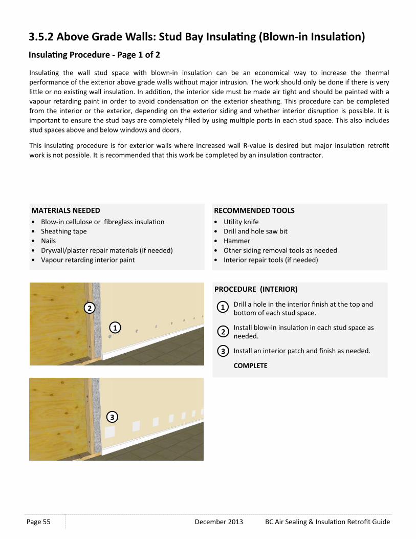
December 2013 BC Air Sealing & Insula�on Retrofit Guide
Page 55
RECOMMENDED TOOLS
• U�lity knife
• Drill and hole saw bit
• Hammer
• Other siding removal tools as needed
• Interior repair tools (if needed)
PROCEDURE (INTERIOR)
Drill a hole in the interior finish at the top and
boNom of each stud space.
Install blow-in insula�on in each stud space as
needed.
Install an interior patch and finish as needed.
COMPLETE
1
2
3
1
2
3
3.5.2 Above Grade Walls: Stud Bay Insula�ng (Blown-in Insula�on)
Insula�ng Procedure - Page 1 of 2
Insula�ng the wall stud space with blown-in insula�on can be an economical way to increase the thermal
performance of the exterior above grade walls without major intrusion. The work should only be done if there is very
liNle or no exis�ng wall insula�on. In addi�on, the interior side must be made air �ght and should be painted with a
vapour retarding paint in order to avoid condensa�on on the exterior sheathing. This procedure can be completed
from the interior or the exterior, depending on the exterior siding and whether interior disrup�on is possible. It is
important to ensure the stud bays are completely filled by using mul�ple ports in each stud space. This also includes
stud spaces above and below windows and doors.
This insula�ng procedure is for exterior walls where increased wall R-value is desired but major insula�on retrofit
work is not possible. It is recommended that this work be completed by an insula�on contractor.
MATERIALS NEEDED
• Blow-in cellulose or fibreglass insula�on
• Sheathing tape
• Nails
• Drywall/plaster repair materials (if needed)
• Vapour retarding interior paint
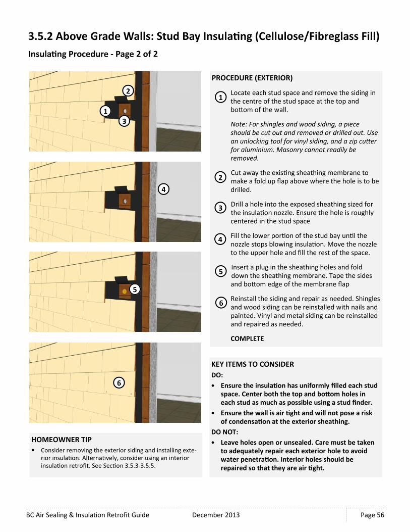
BC Air Sealing & Insula�on Retrofit Guide December 2013
Page 56
4
1
2
3
3.5.2 Above Grade Walls: Stud Bay Insula�ng (Cellulose/Fibreglass Fill)
Insula�ng Procedure - Page 2 of 2
PROCEDURE (EXTERIOR)
Locate each stud space and remove the siding in
the centre of the stud space at the top and
boNom of the wall.
Note: For shingles and wood siding, a piece
should be cut out and removed or drilled out. Use
an unlocking tool for vinyl siding, and a zip cuEer
for aluminium. Masonry cannot readily be
removed.
Cut away the exis�ng sheathing membrane to
make a fold up flap above where the hole is to be
drilled.
Drill a hole into the exposed sheathing sized for
the insula�on nozzle. Ensure the hole is roughly
centered in the stud space
Fill the lower por�on of the stud bay un�l the
nozzle stops blowing insula�on. Move the nozzle
to the upper hole and fill the rest of the space.
Insert a plug in the sheathing holes and fold
down the sheathing membrane. Tape the sides
and boNom edge of the membrane flap
Reinstall the siding and repair as needed. Shingles
and wood siding can be reinstalled with nails and
painted. Vinyl and metal siding can be reinstalled
and repaired as needed.
COMPLETE
5
6
1
2
4
3
KEY ITEMS TO CONSIDER
DO:
• Ensure the insula�on has uniformly filled each stud
space. Center both the top and boGom holes in
each stud as much as possible using a stud finder.
• Ensure the wall is air �ght and will not pose a risk
of condensa�on at the exterior sheathing.
DO NOT:
• Leave holes open or unsealed. Care must be taken
to adequately repair each exterior hole to avoid
water penetra�on. Interior holes should be
repaired so that they are air �ght.
HOMEOWNER TIP
• Consider removing the exterior siding and installing exte-
rior insula�on. Alterna�vely, consider using an interior
insula�on retrofit. See Sec�on 3.5.3-3.5.5.
5
6

December 2013 BC Air Sealing & Insula�on Retrofit Guide
Page 57
3.5.3 Above Grade Walls: Exterior Wall Retrofit
Interior vs. Exterior Insula�on
Insula�ng exterior walls as part of energy efficiency measures for
the whole house can significantly reduce energy consump�on and
save hea�ng and cooling costs. While major insula�on retrofits are
generally more cost effec�ve when combined with interior or
exterior work already taking place, the poten�al energy savings
can also be a compelling reason to ini�ate work.
As with all major insula�on retrofit work, insula�ng the walls from
the interior side is best suited for when interior remodelling is
taking place, and when interior space will allow for some loss of
floor space. Older homes do not generally have sufficiently thick
walls to accommodate added insula�on within the stud space. In
order to make the future energy savings retrofit worthwhile,
addi�onal wall framing is likely necessary on the interior side of
the exis�ng framing to provide a larger wall cavity to
accommodate more insula�on and a higher R-value. The
advantages of insula�ng from the interior are that no exterior
work is needed. The main disadvantage of interior insula�ng is the
increased risk of condensa�on and reduced drying ability due to
colder exterior sheathing temperatures. Special care must be
taken to make the interior plane of air�ghtness effec�ve in order
to avoid air leakage and vapour diffusion condensa�on.
Exterior insula�ng makes the most sense when exterior work is
already taking place and the exis�ng cladding and wall membrane
is removed. It is important that the property setback distances are
not encroached when considering the exterior insula�on thickness
to achieve the desired R-value. Insula�ng from the exterior is also
the best way to ensure a proper air barrier is installed on the
exterior walls, to increase the air �ghtness of the home, and to
simplify the air sealing procedures. One major advantage of
exterior insula�on is that the insula�on can be installed in a single
plane without thermal bridging from studs or floor joists. In
addi�on, the exis�ng framing and sheathing is kept warm,
reducing the risk of condensa�on and decay. The exterior
insula�on aNachment strategy is important to the integrity of the
whole wall system. Special care must be taken to ensure the
insula�on and siding will remain aNached to the wall and will not
allow excess moisture into the system.
The following two sec�ons cover two conceptual interior and
exterior insula�on retrofits that could be performed on an exis�ng
wood frame home. The retrofit work on the exterior walls can be
extensive and therefore it is recommended the work be completed
by experienced contractors. Interior and exterior insula�ng strategies as part
of retrofi�ng procedures for the whole house.

BC Air Sealing & Insula�on Retrofit Guide December 2013
Page 58
3.5.4 Above Grade Walls: Interior Insula�on
Insula�ng Procedure - Conceptual - Page 1 of 1
An interior insula�on retrofit is best performed in conjunc�on with other interior
demoli�on or remodeling work. A double stud approach is used to ensure the wall
cavity is deep enough to achieve adequate wall R-value, and to avoid excessive
thermal bridging. The main focus with all interior insula�on retrofits is making the
interior plane properly air �ght and closed to vapour diffusion as deep stud walls
present a rela�vely high risk of condensa�on on the exterior sheathing.
The following design considera�ons are for a double stud retrofit. The informa�on
is meant to give an overview of the wall assembly and work required.
DESIGN CONSIDERATIONS
Exis�ng finishes and insula�on (if any) removed
and the exterior wall assembly exposed. Framing
and sheathing inspected and repaired as needed.
Inner stud wall constructed with framing as
required, with a gap between the interior and
exterior stud wall sized according to the desired R
-value. All edges along the floor and ceiling sealed
with polyurethane sealant.
Stud space insulated with blow-in or baN
insula�on.
2 1
5
3
Polyethylene air barrier/vapour retarder installed
and sealed at all joints and laps, at all
penetra�ons, and sealed to the interior framing.
Note: The polyethylene should run across the
plane of the interior framing where interior
dividing walls intersect with the exterior wall,
ensuring air barrier con�nuity. Alternate
materials may be used as long as the air barrier
system is con�nuous.
Interior gypsum board installed and finished as
required.
1
2
3
4
5
4

December 2013 BC Air Sealing & Insula�on Retrofit Guide
Page 59
3.5.5 Above Grade Walls: Exterior Insula�on
Insula�ng Procedure - Conceptual - Page 1 of 1
An exterior insula�on retrofit is most economical when it is done in
conjunc�on with other exterior remodelling work. It is important that the
exis�ng wall is stripped down to the sheathing. In addi�on, the interior wall
assembly should be verified to ensure the exterior work will not create a risk of
condensa�on or trap moisture within the assembly. As a general rule, only
vapour permeable air barrier membranes and insula�on should be used on the
exterior of the wall.
The following design considera�ons are for an exterior insula�on retrofit. The
informa�on is meant to give an overview of the wall assembly and work
required.
DESIGN CONSIDERATIONS
Exis�ng siding and wall membrane removed and
the exterior wall assembly exposed. Framing and
sheathing inspected and repaired as needed.
Vapour permeable air barrier membrane (sheet,
self adhered, or liquid applied). Laps and
penetra�ons sealed (if needed) and rim joists and
interfaces covered.
Rigid stone wool insula�on placed over air barrier
membrane. Stone wool to be adequately rigid to
sustain pressure from strapping and support
cladding.
2
1
5
3
Pressure treated wood strapping (or plywood)
aligned with stud spacing where possible.
ANached with screws through the insula�on into
the exis�ng wall.
Exterior siding installed. Most cladding types are
well supported by screws and strapping. Heavy
weight cladding like stone veneer or brick may
require extra support.
See reference documents for addi�onal
considera�ons and details.
1
2
3
4
5
4

BC Air Sealing & Insula�on Retrofit Guide December 2013
Page 60
4. References, Specifica�ons, Standards and Further Informa�on
FURTHER INFORMATION & GUIDELINE DOCUMENTS
Weatheriza�on & Builders Construc�on Guides
Best Prac�ces for Window and Door Replacement in Wood-Frame Buildings, 2013. Homeowner Protec�on Office, A
Branch of BC Housing.
Canadian Home Builders’ Associa�on Builders’ Manual. 2013. Canadian Homes Builders’ Associa�on. ONawa,
Ontario. Available online: hNp://www.chba.ca/buildermanual.aspx
Energy Out West, Weatherisa�on Field Manual, Best Prac�ces for the Weatherisa�on Assistance Program, 2005.
Department of Energy—SeaNle Regional Office, and Energy Outwest. Available online: hNp://
www.energyoutwest.org/eow_library/__presenta�ons_docs/_policy_specifica�ons/EOWFieldGuide.pdf
Guide to A�c Air Sealing, 2010. Joseph Ls�burek, Building Science Corpora�on. Available online:
www.buildingscience.com
Insulate and Weatherize. 2002. Tauton Press - Build Like a Pro™ Series, Author: Bruce Harley.
Keeping the Heat In, 2012. Natural Resources Canada. Available online: hNp://oee.nrcan.gc.ca/sites/
oee.nrcan.gc.ca/files/files/residen�al/personal/documents/Keeping-the-Heat-In_e.pdf
Mass Save Deep Energy Retrofit Builder Guide. 2013. Building Science Corpora�on.
Building Materials & Durability
Bina�onal SoKwood Lumber Council, 2013. Website: hNp://www.soKwoodlumber.org/why-wood/wood-
durability.html
MATERIAL SPECIFICATIONS, CERTIFICATION & STANDARDS
Fire rated Sealants
Required Cer�fica�on - UL Cer�fica�on—UL1479.
Relevant Test Methods: ASTM 814
Insula�on Products
Relevant Test Methods: CAN/ULC-S701, CAN/ULC-S702, CAN/ULC-S703, CAN/ULC-S704, CAN/ULC-S705, ASTM
C177, ASTM C518, ASTM C976, CFR Title 16 - Part 460, ICC-ES AC12, ICC-ES AC377, ASTM E84
Sealants for Air Sealing
Relevant Test Methods: Foam sealants: ASTM C1642, Acrylic silicone and urethane caulking: ASTM C920
Required Cer�fica�on: Water based duct sealant: UL-181A-M, UL 181B-M
Tapes (For Ducts)
Required Cer�fica�on: UL-181
Tapes (for Air Sealing)
Relevant Test Methods: ASTM D3330, ASTM D882
Weather-stripping
Relevant Test Methods: ASTM C509

December 2013 BC Air Sealing & Insula�on Retrofit Guide
Page 61
4. References, Specifica�ons, Standards and Further Informa�on
HEALTH & SAFETY
Combus�on & Gas Safety
CAN/CGSB51.71 The Spillage Test--Method to Determine the Poten�al for Pressure-Induced Spillage from Vented, Fuel
-Fired; Space Hea�ng Appliances; Water Heaters, and Fireplaces. 2005. Canadian General Standards Board
Guide to A�c Air Sealing, 2010. Joseph Ls�burek, Building Science Corpora�on. Available online:
www.buildingscience.com
Keeping the Heat In, 2012. Natural Resources Canada. Available online: hNp://oee.nrcan.gc.ca/sites/oee.nrcan.gc.ca/
files/files/residen�al/personal/documents/Keeping-the-Heat-In_e.pdf
Lead Paint
Lead-Containing Paints and Coa�ngs—Preven�ng Exposure in the Construc�on Industry. WorkSafeBC Publica�on.
Available online: hEp://www.worksafebc.com/publica�ons/high_resolu�on_publica�ons/assets/pdf/bk93.pdf
Asbestos Hazards
Asbestos Hazards When Renova�ng Older Homes. WorkSafeBC Publica�on. Avaialble online: hEp://
www.worksafebc.com/publica�ons/health_and_safety/by_topic/assets/pdf/asbestos_hazards_homeowners.pdf
Safe Work Prac�ces for Handling Asbestos. WorkSafeBC Publica�on. Available online: hEp://www.worksafebc.com/
publica�ons/health_and_safety/by_topic/assets/pdf/asbestos_hazards_homeowners.pdf
Health Canada - It’s Your Health Website. hEp://www.hc-sc.gc.ca/hl-vs/iyh-vsv/environ/asbestos-amiante-eng.php
It’s Your Health—Vermiculite Insula�on Containing Amphibole Asbestos. Health Canada publica�on. Available online:
hEp://www.hc-sc.gc.ca/hl-vs/alt_formats/pacrb-dgapcr/pdf/iyh-vsv/prod/insula�on-isolant-eng.pdf
Mould & Moisture
A Brief Guide to Mold, Moisture, and Your Home. United States Environmental Protec�on Agency Publica�on.
Available online: hEp://www.epa.gov/iedmold1/moldguide.html
Guidelines on Assessment and Remedia�on of Fungi in Indoor Environments. New York City Department of Health and
Mental Hygiene. 2008. Available online. hNp://www.nyc.gov/html/doh/downloads/pdf/epi/epi-mold-guidelines.pdf
WorkSafeBC OHS Guidelines - Part 4 Indoor Air Quality. Available online: hEps://www2.worksafebc.com/Publica�ons/
OHSRegula�on/GuidelinePart4.asp?ReportID=31162
Radon
Radon in Homes and Other Dwellings. HealthLink BC Publica�on. Available Online: hEp://www.healthlinkbc.ca/
healthfiles/hfile42.stm
Sprayfoam Insula�on
Spray Polyurethane Foam (SPF) Home—Design for the Environment, an EPA Partnership Program. United States
Environmental Protec�on Agency. Available online: hEp://www.epa.gov/dfe/pubs/projects/spf/
spray_polyurethane_foam.html
Home Ven�la�on
TECA Quality First Ven�la�on Guidelines. 2008. TECA, Surrey, BC. Available online: hEp://www.teca.ca/
Canadian Home Builder’s Associa�on Builders’ Manual—Chapter 18 Ven�la�on Systems. 2013. Canadian Homes
Builders’ Associa�on. OEawa, Ontario. Available online: hEp://www.chba.ca/buildermanual.aspx

BC Air Sealing & Insula�on Retrofit Guide December 2013
Page 62
4. References, Specifica�ons, Standards and Further Informa�on
In addi�on to the previously noted specifica�ons, standards and suggested further informa�on and guides, the
following references were consulted in the development of this guide.
REFERENCES
Air Sealing Homes for Energy Conserva�on. 1984. Canada Energy, Mines and Resources Canada. Building Energy
Technology Transfer Program. Prepared by Marbek Resource Consultants.
Building Enclosure Design Guide—Wood-frame Mul�-Unit Residen�al Buildings. 2011. Homeowner Protec�on
Office, A Branch of BC Housing.
Energy Conserva�on Assistance Program (ECAP) Program Specifica�ons, 2013. BC Hydro and For�s BC.
Guide for Designing Energy-Efficiency Building Enclosures for Wood-Frame Mul�-Unit Residen�al Buildings in
Marine to Cold Climate Zones in North America. 2013. FP Innova�ons. Available online: hNp://
www.fpinnova�ons.ca/ResearchProgram/AdvancedBuildingSystem/designing-energy-efficient-building-
enclosures.pdf
Insula�on: A guide for Contractors to Share with Homeowners. May 2012. US Department of Energy—Building
Technologies Program. Volume 17, Building America Best Prac�ces Series. Prepared by Pacific Northwest Na�onal
Laboratory & Oak Ridge Na�onal Laboratory. Available online: hNp://apps1.eere.energy.gov/buildings/
publica�ons/pdfs/building_america/insula�on_guide.pdf
Sealing caulking and weatherstripping. Manitoba Hydro. hNp://www.hydro.mb.ca/your_home/
resources/1_sealing_caulking_weatherstripping.pdf
Moisture Control for Dense-Packed Roof Assemblies in Cold Climates: Final Measure Guideline. 2012. Building
Science Press. Research Report 1308 - Authors Chris Schumacher and Robert Lepage. US Department of Energy &
Renewable Energy Building Technologies Program.
RDH Building Engineering Ltd. Near Net Zero Energy Retrofits for Houses. 2011. Canada Mortgage and Housing
Corpora�on.
Retrofit Techniques and Technologies: Air Sealing—A Guide for Contractors to Share with Homeowners. 2010.
Pacific Northwest Na�onal Laboratory and Oak Ridge Na�onal Laboratory.
State of Maine, Maine Weatheriza�on Standards, January 2005.
US Department of Energy, Weatheriza�on Assistance program Standard Training Curricula, 2010.
US Department of Energy, Standard work Specifica�ons for Single Family Home energy Upgrades, March 2013.
US Department of Energy, Building Technologies Program. Website: hNp://www1.eere.energy.gov/buildings/
residen�al/
Vermont Department for Children & Families, Office for Economic Opportunity, Vermont’s Weatheriza�on Program
Technical Policies & Procedures Manual, 2010.

December 2013 BC Air Sealing & Insula�on Retrofit Guide
Page 63
Appendices

BC Air Sealing & Insula�on Retrofit Guide December 2013
Page 64
Contractor Checklist - Home Air Sealing and Insula�on Procedures
Home Address
City Contractor
Location Section
Number Inspection Guideline
Insp
ect
ed
an
d
acc
ep
tab
le
Co
rre
ctio
n
Ne
ed
ed
No
t O
bse
rve
d/
No
t a
pp
lica
ble
Note
Att
ic a
nd
Ro
ofs
3.1.1 Recessed pot lights are covered
3.1.2 Bathroom fan and ductwork is sealed
and insulated
3.1.3 Kitchen range, dryer vent or other duct
work is sealed and insulated
3.1.4 Fireplace of combustion appliance duct
3.1.5 Masonry chimney air sealing
3.1.6 Attic hatch
3.1.7 Top plat & service penetrations
3.1.8 Large openings, shafts or exposed
ceilings
3.1.9 Attic Knee wall insulation
3.1.10 Insulation top up/continuous air barrier
3.1.11 Flash and fill
Va
ult
ed
Ce
ilin
gs
3.1.12 Air sealing (Interior)
3.1.13 Interior versus exterior insulation
assessment
3.1.14 Interior insulation installation
3.1.15 Exterior insulation installation
Be
low
Gra
de
Wa
lls 3.2.1 Air sealing joints & cracks
3.2.2 Interior versus exterior insulation
assessment
3.2.3 Interior insulation installation
3.2.4 Exterior insulation installation
Cra
wl
spa
ce 3.3.1 Air seal and insulated suspended floor
3.3.1 Vented to unvented assessment
Exp
ose
d
Flo
or
3.4.1 Air seal and insulated overhanging floor
3.4.2 Air sealing and insulating exterior floors
Ab
ove
Gra
de
Wa
lls 3.5.1 Air sealing penetrations
3.5.2 Stud bay insulation
3.5.3 Interior versus exterior insulation
assessment
3.5.4 Interior Insulation
3.5.5 Exterior Insulation

December 2013 BC Air Sealing & Insula�on Retrofit Guide
Page 65
Contractor Checklist - Health and Safety
As discussed in Sec�on 1.4 of this guide, there are various health and safety considera�ons for weatheriza�on work
and this page provides a checklist as a reference for contractors. This checklist does not provide comprehensive
coverage of all health and safety considera�ons for performing this type of work as It is expected that the
contractor performing the work be adequately trained and aware of the relevant safety risks.
Poten�al health and safety considera�ons:
� Ven�la�on while Performing Work Many commonly used construc�on materials release poten�ally harmful chemicals and adequate ven�la�on should be provided during work to maintain the health and safety of the workers.
� Ven�la�on of the Home Adequate ven�la�on of the home should be maintained aKer weatheriza�on work to maintain a healthy and comfortable indoor environment.
� Radon Gas Radon gas is a colourless, odourless gas that when present in significant concentra�ons can create long-term health risks for occupants. When performing work in areas where radon is a poten�al concern, tes�ng should be performed.
� Combus�on Safety Weatheriza�on work can affect the combus�on safety of a home and appropriate measures should be taken to ensure that adequate make-up air is provided for combus�on appliances such that spillage of combus�on gases in to the home is avoided.
� Weatheriza�on Materials Common weatheriza�on materials such as sprayfoams, sealants, and adhesives can contain various harmful substances which may nega�vely impact the health of both workers and home occupants. Material selec�on and placement, and ven�la�on should be considered to mi�gate these poten�al nega�ve effects.
� Structural Elements and Connec�ons These elements should not be compromised during weatheriza�on work.
� Mould, Fungal Growth, and Moisture Damage Moisture damage and associated mould and fungal growth are a significant health and building durability concern which should be addressed prior to or as part of weatheriza�on work. It is important to address the roof cause of these issues, and not only the symptoms.
� Asbestos & Lead Older building materials commonly included poten�ally harmful cons�tuents such as asbestos and lead. When these materials are present, appropriate abatement strategies should be implemented.
� Electrical Safety and Wiring Care must be taken to avoid electrical hazards while performing work. Also, in some older homes knob and tube type wiring may s�ll be ac�ve and should be removed prior to weatheriza�on work.
� Gas Safety Qualified contractors should be retained when weatheriza�on work requires the temporary movement or permanent reloca�on of gas lines or equipment.

BC Air Sealing & Insula�on Retrofit Guide December 2013
Page 66
Glossary of Terms and Materials
ACH50 The number of �mes the air in a space changes in an hour (air changes per hour) when the
space is pressurized or depressurized to 50 Pa.
acous�cal sealant A standard sealant which is designed for interior use where it will not be exposed to exterior
condi�ons which may nega�vely affect its performance.
air barrier The materials and components that together control the airflow through an assembly and limit
the poten�al for heat loss and condensa�on.
air leakage The uncontrolled flow of air though the building enclosure (i.e. infiltra�on or exfiltra�on) as the
result of pressure differences and enclosure air�ghtness
air�ghtness A measure of the air permeance of the assemblies that make up the building enclosure at a
certain pressure difference. Air�ghtness can be visualized in terms of an equivalent-sized hole
in the building enclosure. Typically, air�ghtness is measured at a standard test pressure of 50
or 75 Pa to overcome the effects of wind and stack effect, and to obtain a repeatable
measurement.
assembly The arrangement of more than one material or component for the purpose of performing
specific overall func�ons.
ASTM American Society for Tes�ng and Materials
AT rated A designa�on for electrical appliances which iden�fies them as air�ght.
baN insula�on Typically rela�vely low-density fibrous insula�on and designed for installa�on between studs
BCBC Bri�sh Columbia Building Code
below-grade The por�on of a building that is below the ground surface level.
boNom plate The lower horizontal member of a wood-frame wall on which the boNom of the wall studs and
the floor-framing members rest. Also called a sill plate.
building enclosure Referred to in building codes as one type of environmental separator, it comprises the parts of
the building that separate inside condi�oned space from uncondi�oned or outside space while
facilita�ng climate control.
cellulose insula�on Insula�on made from processed wood fibers. Is commonly used as blow-in insula�on in aDcs
or between studs.
combus�ble
construc�on
Construc�on that does not meet the requirements for non-combus�ble construc�on.
condensa�on The appearance of moisture on a surface caused by air coming into contact with a surface that
is at or below the dew point temperature of the air.
detail A loca�on within a building enclosure assembly where the typical assembly construc�on is
interrupted by a penetra�on of the assembly or of interfaces with an adjacent assembly.
dew point The temperature at which air is saturated with water vapour (100% RH). An adjacent surface at
a temperature lower than the dew point will lead to the forma�on of condensa�on on the
surface.

December 2013 BC Air Sealing & Insula�on Retrofit Guide
Page 67
drain mat A sheet typically consis�ng of dimpled plas�c or similar which facilitates the drainage of water
between adjacent materials
drying A water management principle that u�lizes features and materials to speed diffusion and
evapora�on of water from materials that get wet within an assembly.
EEM Energy Efficiency Measure
extruded polystyrene
insula�on (XPS)
A rigid foam plas�c insula�on product which can be used in various applica�ons including those
where air�ghtness is required (when joints appropriately sealed).
fire resistant silicone
sealant
A silicone sealant designed specifically for use in high temperature applica�ons. These sealants
are commonly used as part of fire and smoke control strategies.
foil tape Tape with aluminum facer which can be used for air sealing. The aluminum facer can also
provide a suitable substrate for applica�on of sealants.
gypsum drywall
(gypsum wall board)
Gypsum boards typically faced with paper for interior applica�ons (other facers available for
exterior applica�ons) which can be used as part of an air barrier system and is also widely used
to provide interior finishing.
HDD
(Hea�ng Degree Days)
Hea�ng Degree Days is a measure that is intended to indicate the rela�ve demand for hea�ng
of a building. It is derived from the exterior temperature and the amount of �me for which the
temperatures occur.
insula�on baffle Insula�on baffles are typically preformed foam plas�c products and are used at soffits to
maintain ven�la�on space between the roof sheathing and aDc insula�on so that the
insula�on does not restrict ven�la�on of the aDc space.
penetra�on An inten�onal opening through an assembly for duct, electrical wires, pipes, fasteners, et
cetera to pass through.
polyethylene sheet Plas�c sheet commonly used as a vapour barrier and in some applica�ons may also be used as
an air barrier when appropriately sealed
polyurethane sealant Urethane based sealant which can be suitable for both air and water sealing applica�ons.
rela�ve humidity (RH) The ra�o of the amount of water vapour in a volume of air to the maximum amount of water
vapour that volume of air can hold at a given temperature.
repair The localized or minor reconstruc�on of assemblies, components, or materials so that it can
fulfill its originally intended func�on.
sealant An elastomeric material that is used to form an air�ght (or waterproof) bond at a joint of
opening.
sheathing A material that is used to provide structural s�ffness to the wall framing and structural backing
to the cladding and sheathing membrane. Oriented strand board (OSB) or plywood is typically
used.
sheathing tape Tape typically used for air sealing of the joints between sheet and board products
sill plate See boNom plate.

BC Air Sealing & Insula�on Retrofit Guide December 2013
Page 68
spray polyurethane
sealant/foam (SPF)
A urethane based spray applied foam plas�c product used for air sealing and insula�on and in
some cases can also be used as a water resistant barrier. This product comes in two primary
types: open-cell and closed-cell, which are also commonly referred to as 1lb and 2lb foams
(corresponding with their densi�es per cubic foot), or 1-part and 2-part foams. Open-cell
foams are typically most applicable for air-sealing of rela�vely small openings, and rela�ve to
closed-cell foams, open cell foams expand more when applied, and are more flexible and more
vapour permeable once they are cured. Closed-cell foams are most applicable for larger
applica�ons such as insula�ng between floor joists and other large penetra�ons. Closed-cell
foams are typically vapour impermeable.
stud A ver�cal framing member used in walls and par��ons.
TECA Thermal Environmental Comfort Associa�on
VOC Vola�le Organic Compound
ven�la�on The process of supplying air to or removing air from a space for the purpose of controlling air–
contaminate levels, humidity, or temperature within the space.
vapour retarder A material with low vapour permeability that is located with an assembly to control the flow of
water vapour. Also some�mes referred to as the vapour barrier.
ven�la�on The process of supplying air to or removing air from a space for the purpose of controlling air–
contaminate levels, humidity, or temperature within the space.
vapour retarding paint Typically interior paint which is rela�vely vapour impermeable (approximately <1 perm)