baumann pneumatic actuators · instruction manual d103352x012 baumann pneumatic actuators june 2017...
TRANSCRIPT
www.Fisher.com
Baumann™ Pneumatic Actuators
ContentsIntroduction 1. . . . . . . . . . . . . . . . . . . . . . . . . . . . . . . . . . .
Scope of Manual 1. . . . . . . . . . . . . . . . . . . . . . . . . . . . .Design Notes 2. . . . . . . . . . . . . . . . . . . . . . . . . . . . . . .
Installation 2. . . . . . . . . . . . . . . . . . . . . . . . . . . . . . . . . . . .Attaching an Air-to-Retract (ATR)Actuator to a Valve - Part 1 3. . . . . . . . . . . . . . . . . . . . .Bench Range Adjustment - Air-to-Retract (ATR) Actuator 3. . . . . . . . . . . . . . . . . . .Attaching an Air-to-Retract (ATR)Actuator to a Valve - Part 2 4. . . . . . . . . . . . . . . . . . . . .Attaching an Air-to-Extend (ATE) Actuator to a Valve - Part 1 4. . . . . . . . . . . . . . . . . . . . .
Bench Range Adjustment - Air-to-Extend (ATE) Actuator 5. . . . . . . . . . . . . . . . . . . .Attaching an Air-to-Extend (ATE) Actuator to a Valve - Part 2 5. . . . . . . . . . . . . . . . . . . . .Spring Replacement, Changing Bench Range 6. . . . . .Maintenance 6. . . . . . . . . . . . . . . . . . . . . . . . . . . . . . . . . .Field Conversion - ATE to ATR or ATR to ATE 6. . . . . . .
Removing the Actuator from the Valve 7. . . . . . . . . .Disassembling the Actuator 8. . . . . . . . . . . . . . . . . . .Reassembling the ATE Actuator 8. . . . . . . . . . . . . . . .Reassembling the ATR Actuator 9. . . . . . . . . . . . . . . .Actuator Maintenance 9. . . . . . . . . . . . . . . . . . . . . . . .
Handwheel Operation 9. . . . . . . . . . . . . . . . . . . . . . . . .Parts Ordering 24. . . . . . . . . . . . . . . . . . . . . . . . . . . . . . . .
IntroductionThe Baumann multiple-spring diaphragm actuators are powerful and compact devices designed to operate controlvalves, louvers, dampers or mechanical speed adjusting devices. The actuators can provide either direct air-to-extendaction (ATE) or reverse air-to-retract action (ATR). When an ATE actuator is installed on a typical Baumann valve, itprovides an air-to-close (ATC) or fail-open function. When an ATR actuator is installed, it provides an air-to-open (ATO)or fail-closed function. The design features exceptionally low hysteresis due to the absence of side loads imposed bymisalignment of single coiled springs. The use of multiple springs also offers a substantially lower profile.
The units include zinc-plated, epoxy-coated steel diaphragm cases and an epoxy-coated ductile-iron yoke. Stainlesssteel diaphragm cases, actuator stems, and yokes are available for Baumann size 32 and 54 actuators. The Baumannsize 16 actuator comes standard with a stainless steel yoke and epoxy-coated steel diaphragm case. All remainingmetal parts are made of either stainless or zinc plated steel for optimum corrosion resistance.
All actuators are suitable for a standard ambient temperature range of -29 to 71�C (-20 to 160�F); for highertemperature service, an optional design is available, consult your Emerson sales office or Local Business Partner.
Scope of ManualThis instruction manual includes installation, maintenance, and parts information for Baumann pneumatic actuators.
Do not install, operate, or maintain Baumann actuators without being fully trained and qualified in valve, actuator, andaccessory installation, operation, and maintenance. To avoid personal injury or property damage, it is important tocarefully read, understand, and follow all the contents of this manual, including all safety cautions and warnings. If youhave any questions about these instructions, contact your Emerson sales office or Local Business Partner beforeproceeding.
Instruction ManualD103352X012
Baumann Pneumatic ActuatorsJune 2017
Instruction ManualD103352X012
Baumann Pneumatic ActuatorsJune 2017
2
Design NotesThe same basic actuator may be configured in several ways. Variations may produce either a 7.9 mm (5/16 inch), 12.7mm (1/2 inch), or 19.1 mm (3/4 inch) stroke. The spring tables list the nominal bench spring ranges. Each line in thetable lists the high and low limits for the signal air pressure, measured in bar and pounds per square inch (psi). Thesesignal pressures produce the rated stroke lengths when the actuator is not loaded. The signal air connections use 1/4NPT fittings, and are located in both the lower (key 43) and upper (key 44) diaphragm cases. Use the lower connectionfor an air-to-retract (ATR) actuator and the upper connection for an air-to-extend (ATE) actuator. The signal airpressure must not exceed 2.4 bar (35 psi). Higher pressures may cause the diaphragm to leak.
Installation
WARNING
Always wear protective gloves, clothing and eyewear when performing any installation operations to avoid personal injury.
To avoid personal injury or property damage resulting from the bursting of pressure retaining parts, be certain the serviceconditions do not exceed either the valve body rating or the flange joint rating, or other limits given on the nameplate. Usepressure‐relieving or pressure‐limiting devices to prevent the service conditions from exceeding these limits.
Check with your process or safety engineer for any additional measures that must be taken to protect against processmedia.
If installing into an existing application, also refer to the WARNING at the beginning of the Maintenance section on page 6in this manual.
CAUTION
Often, these types of actuators are attached to valves which include a stainless steel stem and valve seat. When assemblingor adjusting the actuators, never turn the valve stem when the plug is touching the valve seat. If the two stainless steelparts rotate while they are touching, they can be damaged very easily.
When adjusting the valve stem (key 5), do not grip the stem directly with pliers or a wrench. This will damage the surfaceof the stem, and cause damage to the packing in the valve. Instead, counter-tighten the two locknuts (key 27) on the stemtogether. This will allow you to turn the stem by turning the locknuts with a wrench.
WARNING
Personal injury or equipment damage caused by sudden release of pressure or bursting of parts may result if the valveassembly is installed where service conditions could exceed the limits given in the product literature, the limits on theappropriate nameplates, or the mating pipe flange rating. Use pressure-relieving devices as required by government oraccepted industry codes and good engineering practices. If you cannot determine the ratings and limits for this product,contact your Emerson Automation Solutions sales office before proceeding.
Personal injury could result from packing leakage. The packing might require some readjustment to meet specific serviceconditions.
If you move or work on an actuator installed on a valve with loading pressure applied, keep your hands and tools away fromthe stem travel path to avoid personal injury. Be especially careful when removing the stem connector to release all loadingon the actuator stem whether it be from air pressure on the diaphragm or compression in the actuator springs.
Instruction ManualD103352X012
Baumann Pneumatic ActuatorsJune 2017
3
Likewise take similar care when adjusting or removing any optional travel stop. Refer to the relevant actuator MaintenanceInstructions.
If hoisting the valve, take care to prevent people from being injured in case the hoist or rigging slips. Be sure to useadequate sized hoists and chains or slings to handle the valve.
Attaching an Air-to-Retract (ATR) Actuator to a Valve - Part 1Follow these instructions when assembling the actuator to a valve or other device which provides a positive stop in onedirection.
1. Before starting, identify and locate these parts on the valve assembly, figure 1: stem locknuts (key 27), travelindicator (key 58), bonnet (key 8), yoke drive nut (key 9), and plug and stem assembly (keys 4 and 5). Refer to theassembly instructions for the appropriate Baumann control valve.
2. Place the valve body (key 1) in a vise. Clamp the flat end faces of the valve. DO NOT CLAMP THE SIDES OF THEVALVE. This may distort the shape of the casting, and ruin the valve.
3. Begin to attach the actuator to the valve body, figures 1 and 2 through figure 14, depending on actuator type. Theyoke drive nut (key 9) and travel indicator (key 58) must be removed from the valve body assembly. The hole at thebottom of the actuator yoke (key 17) should fit over the top of the valve stem (key 5). Tilt the top of the actuatorback at an angle so you can access the top of the valve stem (key 5).
4. Position the drive nut (key 9) over the valve stem (key 5) with the flat side facing up. (The rounded side should facedown, toward the top surface of the yoke.)
5. Thread the two locknuts (key 27) onto the valve stem (key 5). Turn both nuts down as far as possible. Lock nutstogether using two wrenches to counter-tighten them. By turning the locked nuts with a wrench, you can turn thevalve stem without damaging the surface of the stem.
6. Place the travel indicator (key 58) over the valve stem (key 5).
7. If applicable, loosen shaft collar (key 25), figure 6, and turn clockwise until it reaches the bottom of the actuatorstem (key 26).
8. Apply anti-seize compound to the first few threads of the valve stem (key 5). Turn the actuator counterclockwise tolocate the first thread on the stem. Thread stem into the actuator a half turn.
9. Apply 1 bar (15 psi) to the signal air port in the lower diaphragm case (key 43). The bottom of the yoke will dropdown and touch the top of the valve bonnet (key 8).
10. By hand, tighten the drive nut (key 9).
11. Using a wrench on the counter-tightened nuts (key 27), turn the stem (key 5) up until you feel a resistance.
12. Using a hammer and punch, tighten the drive nut (key 9).
13. Next, make the bench range adjustment. See the next section.
Bench Range Adjustment Air-to-Retract (ATR) ActuatorThis adjustment sets the valve so that it opens and closes at the correct signal air pressures. On an air-to-retractactuator, when the pressure reaches the low end of the range, the valve should just begin to open. Once the benchrange has been set correctly, the valve should be completely open when it receives full signal air pressure, and thevalve travel should also be correct. The spring tables list the possible pressure ranges for different valve configurations.The signal pressure at the low end of the range is dependent on the springs used in the actuator. In order to make thisadjustment, you will need an adjustable source of compressed air ranging from 0 to 1 bar (0 to 15 psi) for Baumann 16and 32 actuators, 0 to 1.4 bar (0 to 20 psi) for Baumann 54 and 70 actuators with a 1/4 NPT external connector.
1. Connect the air source to the signal air port in the lower diaphragm case (key 43). Begin at 0 bar (0 psi) andgradually increase the pressure. Notice the pressure at the point when the valve stem (key 5) just begins to move.
Instruction ManualD103352X012
Baumann Pneumatic ActuatorsJune 2017
4
a. If the pressure at this point is too low (lower than the recommended bench initials shown in the spring tables),the actuator and stem assembly should be longer. Turn the valve stem (key 5) out of the actuator stem (key 26)1/2 turn.
b. If the pressure at this point is too high, the actuator and stem assembly should be shorter. Turn the valve stem(key 5) into the actuator stem (key 26) 1/2 turn.
2. Adjust the length of the valve stem (key 5) as described above. Always turn the valve stem (key 5) using a wrench onthe two counter-tightened nuts (key 27). Never turn stems while the plug is on the seat.
3. You may have to repeat steps 1 and 2 several times to get the correct setting.
CAUTION
Remember that the valve stem (key 5) cannot be allowed to turn against the valve seat when the two parts are touching.Before you make any adjustment, apply 1 bar (15 psi) to the actuator. This will lift the valve stem away from the seat, andhelp prevent damage.
Attaching an Air-to-Retract (ATR) Actuator to a Valve - Part 21. Once the bench range has been adjusted correctly, you can complete the assembly. Apply 1 bar (15 psi) to the
signal port on the actuator.
2. Using two wrenches, unlock the two counter-tightened nuts (key 27). There are flats on the actuator stem (key 26).Hold these flats with a wrench and, one at a time, turn each nut up as far as possible. Counter-tighten the two nutstogether again.
3. Reduce the air pressure to 0 bar (0 psi). Loosen the screws (key 57) which hold the travel indicator scale (key 56) inplace. Set the scale so the lowest line matches the level of the travel indicator washer.
4. Set the air pressure to the high end of the valve's operating pressure. The travel indicator should move through thefull rated travel of 7.9, 12.7, or 19.1 mm (5/16, 1/2, or 3/4 inch).
Note
The shaft collar (key 25), if applicable, can be set at intermediate positions to provide a minimum opening valve travel stopfollowing calibration.
Attaching an Air-to-Extend (ATE) Actuator to a Valve - Part 1Follow these instructions when assembling the actuator to a valve or another device which provides a positive stop inone direction. (Baumann 70 actuator is ATR only.)
1. Before starting, identify and locate these parts on the valve assembly, figure 1: stem locknuts (key 27), travelindicator (key 58), bonnet (key 8), yoke drive nut (key 9), and plug and stem assembly (keys 4 and 5). Refer to theassembly instructions for the appropriate Baumann control valve.
2. Place the valve body (key 1 in a vise. Clamp the flat end faces of the valve. DO NOT CLAMP THE SIDES OF THE VALVE.This may distort the shape of the casting, and ruin the valve.
3. Begin to attach the actuator to the valve body. The yoke drive nut (key 9) and travel indicator (key 58) must beremoved from the valve body assembly. The hole at the bottom of the actuator yoke (key 17) should fit over the top
Instruction ManualD103352X012
Baumann Pneumatic ActuatorsJune 2017
5
of the valve stem (key 5). Tilt the top of the actuator back at an angle so you can access the top of the valve stem(key 5).
4. Position the drive nut (key 9) over the valve stem (key 5) with the flat side facing up. (The rounded side should facedown, toward the top surface of the yoke.)
5. Thread the two locknuts (key 27) onto the valve stem (key 5). Turn both nuts down as far as possible. Lock nutstogether using two wrenches to counter-tighten them. By turning the locked nuts with a wrench, you can turn thevalve stem without damaging the surface of the stem.
6. Place the travel indicator (key 58) over the valve stem (key 5).
7. If applicable, loosen shaft collar (key 25, figure 6) and turn clockwise until it reaches the bottom of the actuatorstem (key 26).
8. Apply anti-seize compound to the first few threads of the valve stem (key 5). Place the actuator over the top of thevalve bonnet (key 8). The yoke of the actuator will make contact with the top of the bonnet (key 8). Extend the valvestem (key 5) into the actuator stem (key 26). Turn the stem (key 5) until it comes to a stop, then back off 1/2 turn.
9. By hand, tighten the drive nut (key 9).
10. Using a wrench on the counter-tightened nuts (key 27), turn the stem (key 5) up until you feel a resistance.
11. Using a hammer and punch, tighten the drive nut (key 9).
12. Next, make the bench range adjustment. See the next section.
Bench Range Adjustment Air-to-Extend (ATE) ActuatorThis adjustment sets the valve so that it opens and closes at the correct signal air pressures. On an air-to-extendactuator, when the pressure reaches the high end of the range, the valve should be completely closed. Once the benchrange has been set correctly, the valve should be completely open when it receives the low reading for the signal airpressure, and the valve travel should also be correct. The spring tables list the possible pressure ranges for differentvalve configurations. The signal pressure at the high end of the range is dependent on the springs used in the actuator.In order to make this adjustment, you will need an adjustable source of compressed air ranging from 0 to 1 bar (0 to 15psi) for Baumann 16 and 32 actuators, or 0 to 1.4 bar (0 to 20 psi) for Baumann 54 and 70 actuators with a 1/4 NPTexternal connector.
1. Connect the air source to the signal air port in the upper diaphragm case (key 44). Gradually increase the pressuretoward the high rating listed in the appropriate spring table. Notice the pressure at the point when the valve is fullyseated, and the valve stem (key 5) stops moving.
a. If the pressure at this point is too high, the actuator and stem assembly should be longer. Turn the valve stem(key 5) out of the actuator stem (key 26) 1/2 turn.
b. If the pressure at this point is too low, the actuator and stem assembly should be shorter. Turn the valve stem(key 5) into the actuator stem (key 26) 1/2 turn.
2. Adjust the length of the valve stem (key 5) as described in the last step. Always turn the valve stem (key 5) using awrench on the two counter-tightened nuts (key 27).
CAUTION
Remember that the valve stem (key 5) cannot be allowed to turn against the valve seat when the two parts are touching.Before you make any adjustment, be certain that there is no air signal to the actuator.
3. You may have to repeat steps 1 and 2 several times to get the correct setting.
Attaching an Air-to-Extend (ATE) Actuator to a Valve - Part 21. Once the bench range has been adjusted correctly, you can complete the assembly. Apply 0 bar (0 psi) to the signal
port on the actuator.
Instruction ManualD103352X012
Baumann Pneumatic ActuatorsJune 2017
6
2. Using two wrenches, unlock the two counter-tightened nuts (key 27). There are flats on the actuator stem (key 26).Hold the flats with a wrench and, one at a time, turn each nut up until you feel a resistance. Counter-tighten the twonuts together again.
3. Apply 1 bar (15 psi) to the signal port. Loosen the screws (key 57) which hold the travel indicator scale (key 56) inplace. Set the scale so the lowest line matches the level of the travel indicator (key 58).
4. Apply 0 bar (0 psi). The travel indicator (key 58) should move through the full rated travel of 7.9, 12.7, or 19.1 mm(5/16, 1/2, or 3/4 inches).
Spring Replacement, Changing Bench RangeThe springs inside the actuator can be replaced or changed if necessary. This is necessary if you want to change thebench range - the range of pressures over which the actuator is designed to operate. The spring tables list the possiblespring combinations. To use the tables, identify the stroke and the pressure range for the new valve configuration. Thiswill tell you the part number and the quantity of the springs needed.
Figures 2 and 3 for Baumann 16 actuators, figures 4 and 5 for Baumann 32 actuators, figures 10 and 11 for Baumann54 actuators, and figure 14 for Baumann 70 actuators show the correct assembly configurations for air-to-extend andair-to-retract valves. Notice that both types include the same parts, but they are arranged differently. The followingsections detail the disassembly and assembly instructions.
Maintenance
WARNING
Avoid personal injury and property damage from sudden release of process pressure or bursting of parts. Before performingany maintenance operations:
� Do not remove the actuator from the valve while the valve is still pressurized.
� Always wear protective gloves, clothing, and eyewear when performing any maintenance operations.
� Disconnect any operating lines providing air pressure, electric power, or a control signal to the actuator. Be sure theactuator cannot suddenly open or close the valve.
� Use bypass valves or completely shut off the process to isolate the valve from process pressure. Relieve process pressureon both sides of the valve. Drain the process media from both sides of the valve.
� Vent the power actuator loading pressure and relieve any spring precompression.
� Use lock‐out procedures to be sure the above measures stay in effect while you work on the equipment.
� The valve packing box may contain process fluids that are pressurized, even when the valve has been removed from thepipeline. Process fluids may spray out when removing the packing hardware or packing rings, or when loosening thepacking box pipe plug.
� Check with your process or safety engineer for any additional measures that must be taken to protect against processmedia.
Field Conversion - ATE to ATR or ATR to ATEExcept for the Baumann 70, these actuators can be changed in the field from air-to-extend (ATE) operation toair-to-retract operation, or from ATR to ATE operation. If you are making this change without changing the benchrange, you can reuse the same parts. The parts are simply assembled in a different way. This is described in more detailin the following sections. The following sections list the disassembly and reassembly instructions.
Instruction ManualD103352X012
Baumann Pneumatic ActuatorsJune 2017
7
Note
Baumann 70 actuator is available in ATR only.
Field conversion cannot be done on dual-stop actuators.
WARNING
To avoid personal injury or property damage due to actuator springs being under compression, remove the long cap screwslast.
The upper actuator casing may remain fixed to the diaphragm and lower casing during disassembly, even if the casing capscrews have been loosened. If this happens, the actuator springs are still under compression. The upper casing couldsuddenly come loose and jump, due to the compressed energy of the springs. If the upper casing is stuck to the diaphragmand lower casing when you begin loosening the casing cap screws, pry the casings apart with a prying tool. Always be surethat the springs are dispersing energy and the upper casing is moving against the long bolts during disassembly.
WARNING
To avoid personal injury or property damage by uncontrolled movement of the actuator yoke, loosen the body/yoke nuts orbonnet/yoke nuts by following the instructions in the next step. Do not remove a stuck actuator by pulling on it withequipment that can stretch or store energy in any other manner. The sudden release of stored energy can causeuncontrolled movement of the actuator yoke.
Removing the Actuator from the Valve1. For an air-to-retract (ATR) actuator: Apply 1 bar (15 psi) for Baumann 16 and 32 actuators, or 1.4 bar (20 psi) for
Baumann 54 and 70 actuators, to the signal air inlet located in the lower diaphragm case (key 43). This will lift theplug and stem (4/5) away from the valve seat.
For an air-to-extend (ATE) actuator: Disconnect the signal air line connected to the upper diaphragm case (key 43).This will assure that the actuator is vented and that the valve plug and stem (4/5) are fully lifted away from the valveseat.
2. For both types: Place a wrench on the flats of the actuator stem. With an additional wrench, engage the upperlocknut (key 27) on the stem and back out the stem about 6.4 mm (1/4 inch). (This procedure will prevent theactuator stem from turning and causing damage to the diaphragm.)
3. Loosen the yoke drive nut (key 9).
4. Using the wrench to work against one of the counter-tightened nuts, turn the valve stem (key 5) completely downuntil the end unthreads from the actuator stem (key 26).
5. Remove the travel indicator (key 58) from the valve stem (key 5). Loosen the locknuts (key 27) and remove them.Remove the yoke drive nut (key 9).
6. Lift the actuator assembly off of the valve bonnet (key 8).
7. Disconnect airline from ATR actuators.
Instruction ManualD103352X012
Baumann Pneumatic ActuatorsJune 2017
8
Disassembling the Actuator1. Remove the actuator from the valve as described earlier.
2. Remove the cap screws (key 45) and nuts (key 46). Loosen the nuts from the cap screws gradually and evenly. Someunits may have a combination of longer and shorter screws. After removing the shorter screws, the remaininglonger screws must be loosened evenly. The springs put a lot of force on the diaphragm cases (keys 43 and 44). It isimportant to release the spring tension gradually before you try to open them.
3. Remove the upper diaphragm case (key 44) and note the position of the parts inside. For the Baumann 70 actuator,the upper diaphragm plate (key 40) must also be removed.
4. Except for the Baumann 16 actuator, lift out the actuator stem (key 26) with the diaphragm plate (key 40) and thediaphragm (key 39). For the Baumann 16 actuator, loosen locknut (key 30) and remove the stem (key 26) throughthe bottom.
5. For Baumann 32, 54, and 70 actuators, the lower part of the actuator stem (key 26) has flats. Use these flats toclamp the lower end of the stem into a vise. Unscrew the nylon insert locknut (key 30). On an ATE unit, remove thewasher (key 112, key 116 for the Baumann 54 actuator), diaphragm (key 39), diaphragm plate (key 40), and for theBaumann 32 actuator, stop cup (key 79). NOTE: There is not a stop cup for the Baumann 16 actuator. (An ATR unithas the same parts, but they are attached in a different order.)
6. Replace the diaphragm (key 39) and the O-ring(s) (key 50) if these parts are damaged.
Reassembling the ATE Actuator1. Use the flats on the actuator stem (key 26) to grip the lower end of the stem in a vise.
2. For the Baumann 32 actuator, place the stop cup (key 79) in position on the upper end of the stem. On an ATEactuator, the stop cup faces down.
3. Place the diaphragm plate (key 40) on the upper end of the stem (key 26), also facing down.
4. Place the diaphragm (key 39) in position. The curved part of the diaphragm should open downward.
5. Place the washer (key 112, key 116 for the Baumann 54 actuator) over the opening in the diaphragm plate.
6. Thread the nylon insert locknut (key 30) onto the end of the stem (key 26) and tighten it.
7. Turn the assembly upside-down, and grip the nylon insert locknut (key 30) in the vise.
8. Place the springs (key 22) onto the diaphragm plate (key 40). Each spring should be centered on one of the raisedbosses on the plate.
9. Slide the stop collar (key 115) over the free end of the actuator stem (key 26).
10. Check to see that the O-ring (key 50) is in position on the actuator stem (key 26).
11. Apply some light grease to the O-ring (key 50) and to the surface of the actuator stem (key 26).
12. Slide the lower diaphragm case (key 43), with the actuator yoke (key 17) attached, over the actuator stem (key26). Make sure that the outer bolt holes of the lower diaphragm case (key 43) line up with the holes in thediaphragm (key 39). If there is interference with any of the springs, rotate the case into another position.
13. Remove the assembly from the vise. Press on the diaphragm assembly slightly to compress the springs. Flip overthe assembly and reattach the upper diaphragm case (key 44). As you do this, be sure that all of the springs areupright, and none of them are sitting on the bolt heads. Insert the cap screws (key 45) and tighten the nuts (key 46).It may be necessary to compress the springs slightly to start the nuts. Tighten the nuts evenly, and cross from oneside of the assembly to the other as you tighten. This will ensure that the spring tension is taken up evenly.
14. Apply air pressure to the actuator and check for friction or leakage. The actuator should travel smoothly throughthe entire travel range. Apply leak detection fluid to the area around the guide bushing (key 54). Also check for leaksaround the outer edge of the diaphragm (key 39).
15. Make the adjustments described in the section on Bench Range Adjustment - Air-to-Extend (ATE) Valve.
Instruction ManualD103352X012
Baumann Pneumatic ActuatorsJune 2017
9
Reassembling the ATR Actuator1. Use the flats on the actuator stem (key 26) to grip this part in a vise.
2. Place the washer (key 112, key 116 for the Baumann 54 actuator) over the threaded part of the actuator stem (key26).
3. Place the diaphragm (key 39) in position. The curved part of the diaphragm should open upward.
4. Place the diaphragm plate (key 40) onto the upper end of the stem (key 26), also facing up.
5. For the Baumann 32 actuator, place the stop cup (key 79) in position on the upper end of the stem (key 26). On anATR actuator, the stop cup faces up.
6. Thread the nylon insert locknut (key 30) onto the end of the stem (key 26) and tighten it.
7. Slide the stop collar (key 115) over the free end of the actuator stem (key 26).
8. Check to see that the O-ring (key 50) is in position on the actuator stem (key 26).
9. Apply some light grease to the O-ring (key 50), and to the surface of the actuator stem (key 26).
10. Slide the actuator stem into the lower diaphragm case (key 43). Turn the assembly so the holes in the diaphragm(key 39) line up with the holes in the diaphragm case (key 43).
11. Place the springs (key 22) onto the diaphragm plate (key 40). Each spring should be centered on one of the raisedbosses on the plate.
12. Reattach the upper diaphragm case (key 44). As you do this, be sure that each of the springs is upright. Insert thecap screws (key 45) and tighten the nuts (key 46). It may be necessary to press down on the upper diaphragm case(key 44) slightly to compress the springs slightly and start the nuts. Tighten the nuts evenly, and cross from one sideof the assembly to the other as you tighten. This will ensure that the spring tension is taken up evenly.
13. Apply air pressure to the actuator and check for friction or leakage. The actuator should travel smoothly throughthe entire travel range. Apply leak detection fluid to the area around the guide bushing (key 54). Also check for leaksaround the outer edge of the diaphragm.
14. Make the adjustments described in the section on Bench Range Adjustment-Air-to-Retract (ATR) Valve.
WARNING
To avoid personal injury or equipment damage due to possible sudden shifting or falling of the valve assembly, do not liftthe valve assembly by the handwheel.
Actuator MaintenanceA routine maintenance schedule might call for regular replacement of the O-ring(s) (key 50) or the diaphragm (key39). Follow the disassembly and reassembly instructions listed earlier.
Handwheel OperationFor air-to-retract actuators, turn handwheel clockwise to manually retract the stem and counterclockwise to extendthe stem. The small locking knob on top of the handwheel assembly enables the user to lock the desired handwheelposition.
For an air-to-extend actuator, turn the handwheel clockwise to manually extend the stem and counterclockwise toretract the stem. The lever on the handwheel stem enables the user to lock the desired handwheel position.
Instruction ManualD103352X012
Baumann Pneumatic ActuatorsJune 2017
10
E1239
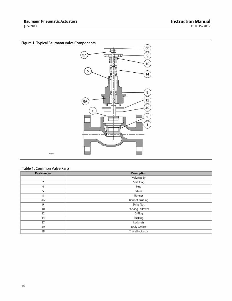
Figure 1. Typical Baumann Valve Components
Table 1. Common Valve PartsKey Number Description
1 Valve Body
2 Seat Ring
4 Plug
5 Stem
8 Bonnet
8A Bonnet Bushing
9 Drive Nut
10 Packing Follower
12 O-Ring
14 Packing
27 Locknuts
49 Body Gasket
58 Travel Indicator
Instruction ManualD103352X012
Baumann Pneumatic ActuatorsJune 2017
11
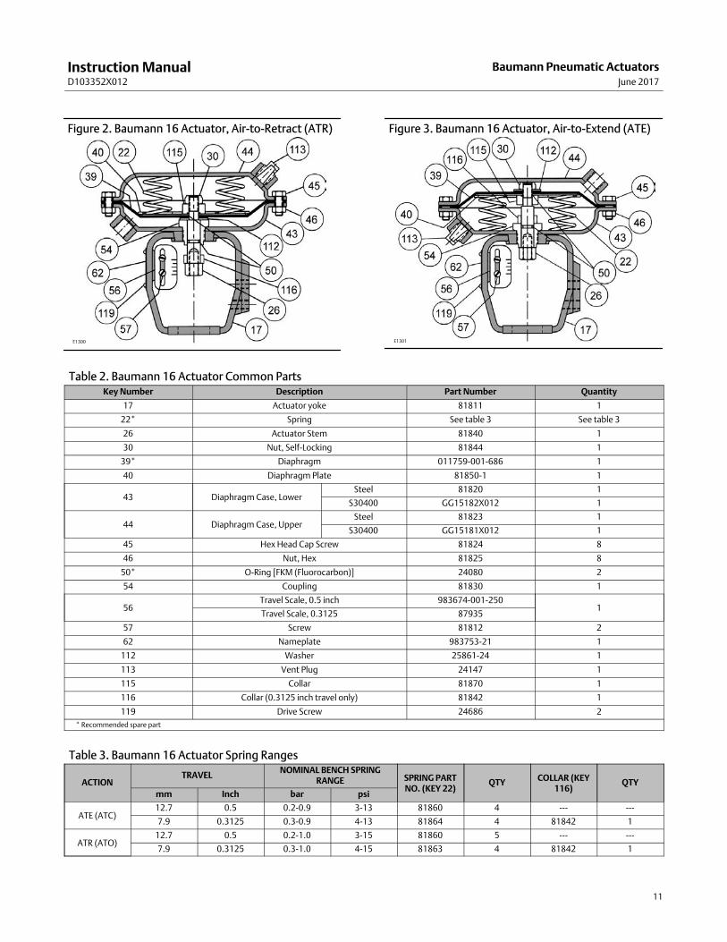
Figure 2. Baumann 16 Actuator, Air-to-Retract (ATR)
E1300
Figure 3. Baumann 16 Actuator, Air-to-Extend (ATE)
E1301
Table 2. Baumann 16 Actuator Common PartsKey Number Description Part Number Quantity
17 Actuator yoke 81811 1
22* Spring See table 3 See table 3
26 Actuator Stem 81840 1
30 Nut, Self-Locking 81844 1
39* Diaphragm 011759-001-686 1
40 Diaphragm Plate 81850-1 1
43 Diaphragm Case, LowerSteel 81820 1
S30400 GG15182X012 1
44 Diaphragm Case, UpperSteel 81823 1
S30400 GG15181X012 1
45 Hex Head Cap Screw 81824 8
46 Nut, Hex 81825 8
50* O-Ring [FKM (Fluorocarbon)] 24080 2
54 Coupling 81830 1
56Travel Scale, 0.5 inch 983674-001-250
1Travel Scale, 0.3125 87935
57 Screw 81812 2
62 Nameplate 983753-21 1
112 Washer 25861-24 1
113 Vent Plug 24147 1
115 Collar 81870 1
116 Collar (0.3125 inch travel only) 81842 1
119 Drive Screw 24686 2
* Recommended spare part
Table 3. Baumann 16 Actuator Spring Ranges
ACTIONTRAVEL
NOMINAL BENCH SPRINGRANGE SPRING PART
NO. (KEY 22)QTY
COLLAR (KEY116)
QTY
mm Inch bar psi
ATE (ATC)12.7 0.5 0.2-0.9 3-13 81860 4 --- ---
7.9 0.3125 0.3-0.9 4-13 81864 4 81842 1
ATR (ATO)12.7 0.5 0.2-1.0 3-15 81860 5 --- ---
7.9 0.3125 0.3-1.0 4-15 81863 4 81842 1
Instruction ManualD103352X012
Baumann Pneumatic ActuatorsJune 2017
12
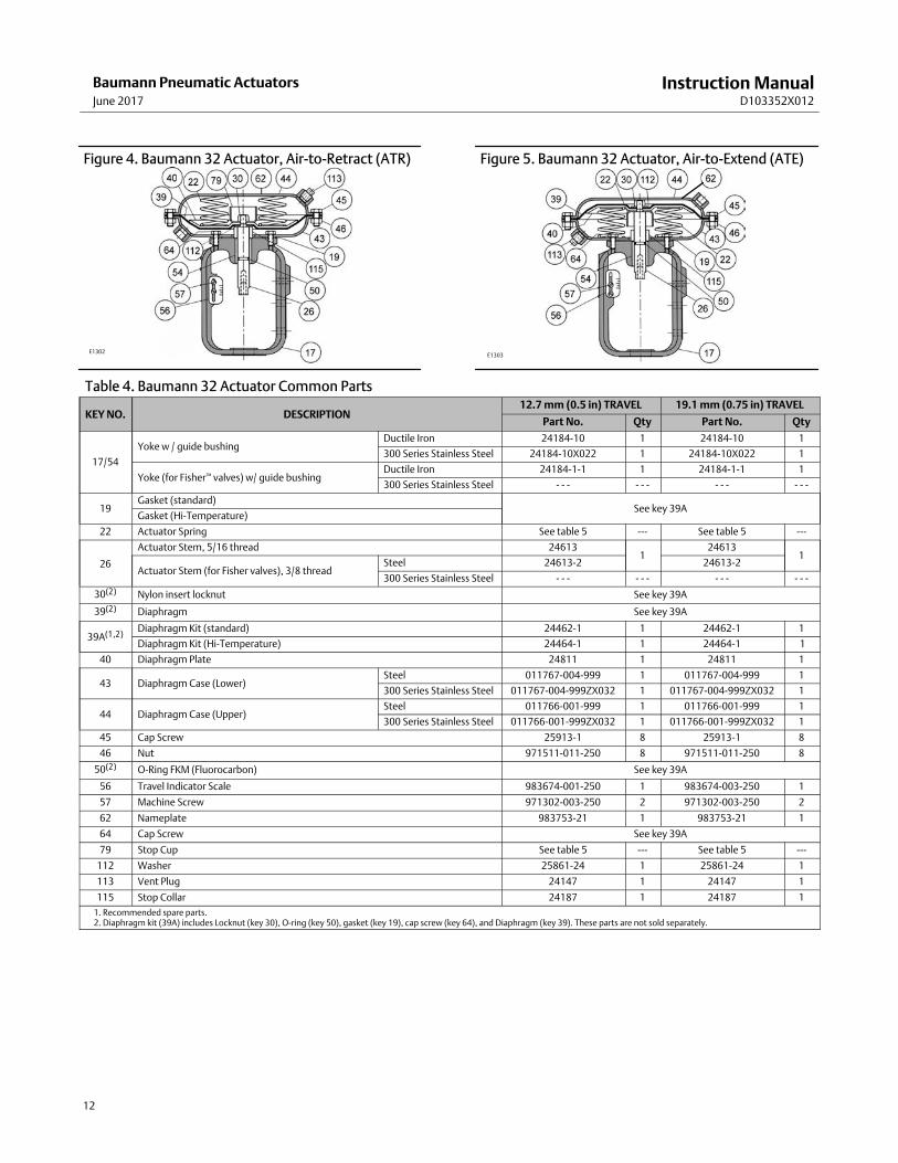
Figure 4. Baumann 32 Actuator, Air-to-Retract (ATR)
E1302
Figure 5. Baumann 32 Actuator, Air-to-Extend (ATE)
E1303
Table 4. Baumann 32 Actuator Common Parts
KEY NO. DESCRIPTION12.7 mm (0.5 in) TRAVEL 19.1 mm (0.75 in) TRAVEL
Part No. Qty Part No. Qty
17/54
Yoke w / guide bushingDuctile Iron 24184-10 1 24184-10 1
300 Series Stainless Steel 24184-10X022 1 24184-10X022 1
Yoke (for Fisher™ valves) w/ guide bushingDuctile Iron 24184-1-1 1 24184-1-1 1
300 Series Stainless Steel - - - - - - - - - - - -
19Gasket (standard)
See key 39AGasket (Hi-Temperature)
22 Actuator Spring See table 5 --- See table 5 ---
26
Actuator Stem, 5/16 thread 246131
246131
Actuator Stem (for Fisher valves), 3/8 threadSteel 24613-2 24613-2
300 Series Stainless Steel - - - - - - - - - - - -
30(2) Nylon insert locknut See key 39A
39(2) Diaphragm See key 39A
39A(1,2)Diaphragm Kit (standard) 24462-1 1 24462-1 1
Diaphragm Kit (Hi-Temperature) 24464-1 1 24464-1 1
40 Diaphragm Plate 24811 1 24811 1
43 Diaphragm Case (Lower)Steel 011767-004-999 1 011767-004-999 1
300 Series Stainless Steel 011767-004-999ZX032 1 011767-004-999ZX032 1
44 Diaphragm Case (Upper)Steel 011766-001-999 1 011766-001-999 1
300 Series Stainless Steel 011766-001-999ZX032 1 011766-001-999ZX032 1
45 Cap Screw 25913-1 8 25913-1 8
46 Nut 971511-011-250 8 971511-011-250 8
50(2) O-Ring FKM (Fluorocarbon) See key 39A
56 Travel Indicator Scale 983674-001-250 1 983674-003-250 1
57 Machine Screw 971302-003-250 2 971302-003-250 2
62 Nameplate 983753-21 1 983753-21 1
64 Cap Screw See key 39A
79 Stop Cup See table 5 --- See table 5 ---
112 Washer 25861-24 1 25861-24 1
113 Vent Plug 24147 1 24147 1
115 Stop Collar 24187 1 24187 1
1. Recommended spare parts.2. Diaphragm kit (39A) includes Locknut (key 30), O-ring (key 50), gasket (key 19), cap screw (key 64), and Diaphragm (key 39). These parts are not sold separately.
Instruction ManualD103352X012
Baumann Pneumatic ActuatorsJune 2017
13
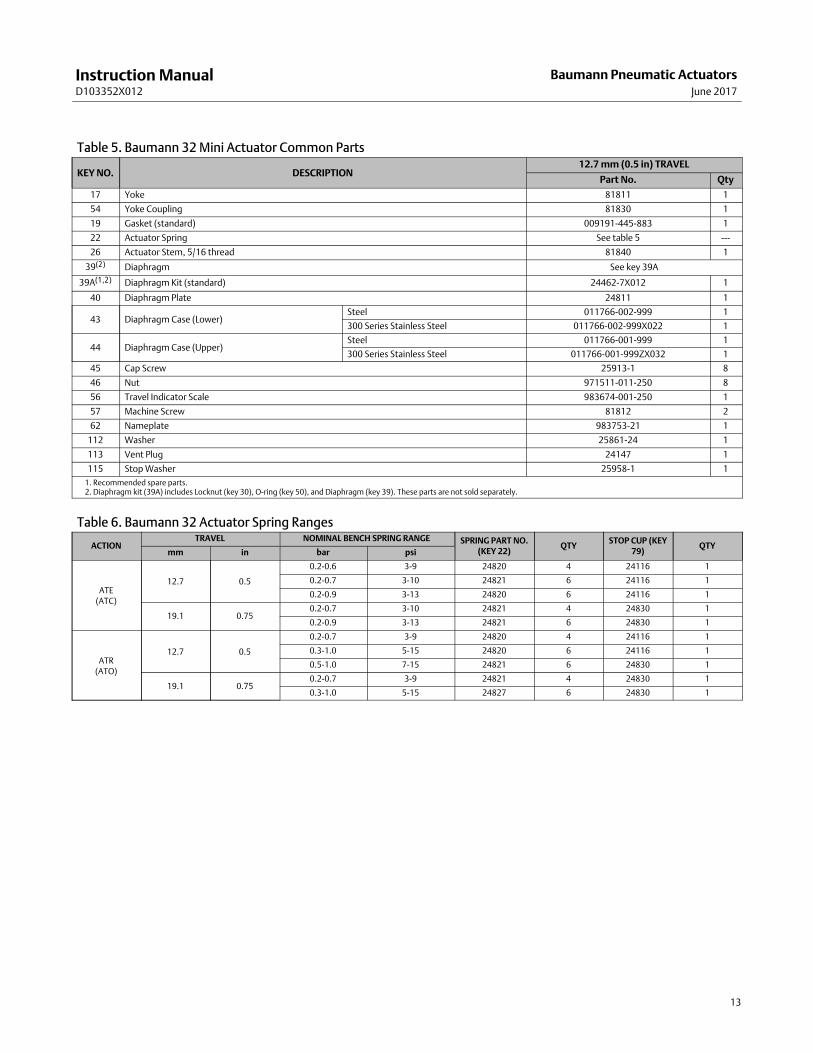
Table 5. Baumann 32 Mini Actuator Common Parts
KEY NO. DESCRIPTION12.7 mm (0.5 in) TRAVEL
Part No. Qty
17 Yoke 81811 1
54 Yoke Coupling 81830 1
19 Gasket (standard) 009191-445-883 1
22 Actuator Spring See table 5 ---
26 Actuator Stem, 5/16 thread 81840 1
39(2) Diaphragm See key 39A
39A(1,2) Diaphragm Kit (standard) 24462-7X012 1
40 Diaphragm Plate 24811 1
43 Diaphragm Case (Lower)Steel 011766-002-999 1
300 Series Stainless Steel 011766-002-999X022 1
44 Diaphragm Case (Upper)Steel 011766-001-999 1
300 Series Stainless Steel 011766-001-999ZX032 1
45 Cap Screw 25913-1 8
46 Nut 971511-011-250 8
56 Travel Indicator Scale 983674-001-250 1
57 Machine Screw 81812 2
62 Nameplate 983753-21 1
112 Washer 25861-24 1
113 Vent Plug 24147 1
115 Stop Washer 25958-1 1
1. Recommended spare parts.2. Diaphragm kit (39A) includes Locknut (key 30), O-ring (key 50), and Diaphragm (key 39). These parts are not sold separately.
Table 6. Baumann 32 Actuator Spring Ranges
ACTIONTRAVEL NOMINAL BENCH SPRING RANGE SPRING PART NO.
(KEY 22)QTY
STOP CUP (KEY79)
QTYmm in bar psi
ATE(ATC)
12.7 0.5
0.2-0.6 3-9 24820 4 24116 1
0.2-0.7 3-10 24821 6 24116 1
0.2-0.9 3-13 24820 6 24116 1
19.1 0.750.2-0.7 3-10 24821 4 24830 1
0.2-0.9 3-13 24821 6 24830 1
ATR(ATO)
12.7 0.5
0.2-0.7 3-9 24820 4 24116 1
0.3-1.0 5-15 24820 6 24116 1
0.5-1.0 7-15 24821 6 24830 1
19.1 0.750.2-0.7 3-9 24821 4 24830 1
0.3-1.0 5-15 24827 6 24830 1
Instruction ManualD103352X012
Baumann Pneumatic ActuatorsJune 2017
14
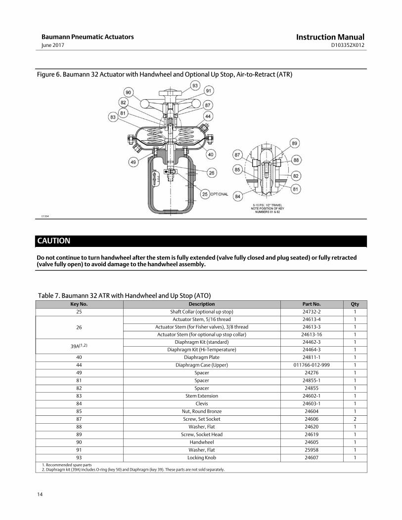
Figure 6. Baumann 32 Actuator with Handwheel and Optional Up Stop, Air-to-Retract (ATR)
E1304
CAUTION
Do not continue to turn handwheel after the stem is fully extended (valve fully closed and plug seated) or fully retracted(valve fully open) to avoid damage to the handwheel assembly.
Table 7. Baumann 32 ATR with Handwheel and Up Stop (ATO)Key No. Description Part No. Qty
25 Shaft Collar (optional up stop) 24732-2 1
26
Actuator Stem, 5/16 thread 24613-4 1
Actuator Stem (for Fisher valves), 3/8 thread 24613-3 1
Actuator Stem (for optional up stop collar) 24613-16 1
39A(1,2)Diaphragm Kit (standard) 24462-3 1
Diaphragm Kit (Hi-Temperature) 24464-3 1
40 Diaphragm Plate 24811-1 1
44 Diaphragm Case (Upper) 011766-012-999 1
49 Spacer 24276 1
81 Spacer 24855-1 1
82 Spacer 24855 1
83 Stem Extension 24602-1 1
84 Clevis 24603-1 1
85 Nut, Round Bronze 24604 1
87 Screw, Set Socket 24606 2
88 Washer, Flat 24620 1
89 Screw, Socket Head 24619 1
90 Handwheel 24605 1
91 Washer, Flat 25958 1
93 Locking Knob 24607 1
1. Recommended spare parts2. Diaphragm kit (39A) includes O-ring (key 50) and Diaphragm (key 39). These parts are not sold separately.
Instruction ManualD103352X012
Baumann Pneumatic ActuatorsJune 2017
15
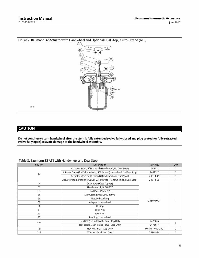
Figure 7. Baumann 32 Actuator with Handwheel and Optional Dual Stop, Air-to-Extend (ATE)
E1305
CAUTION
Do not continue to turn handwheel after the stem is fully extended (valve fully closed and plug seated) or fully retracted(valve fully open) to avoid damage to the handwheel assembly.
Table 8. Baumann 32 ATE with Handwheel and Dual StopKey No. Description Part No. Qty
26
Actuator Stem, 5/16 thread (Handwheel, No Dual Stop) 24613 1
Actuator Stem (for Fisher valves), 3/8 thread (Handwheel, No Dual Stop) 24613-2 1
Actuator Stem, 5/16 thread (Handwheel and Dual Stop) 24613-15 1
Actuator Stem (for Fisher valves), 3/8 thread (Handwheel and Dual Stop) 24613-20 1
44 Diaphragm Case (Upper)
24807T001 1
52 Handwheel, P/N 24605Z
53 Roll Pin, P/N 25897
55 Stem, Handwheel, P/N 25976
58 Nut, Self-Locking
59 Adapter, Handwheel
60 O-Ring
61 Lock-Nut
63 Spring Pin
82 Bushing, Handwheel
126Hex Bolt (0.5 in travel) - Dual Stop Only 24756-6
2Hex Bolt (0.75 in travel) - Dual Stop Only 24756-7
127 Hex Nut - Dual Stop Only 971511-010-250 2
112 Washer - Dual Stop Only 25861-24 1
Instruction ManualD103352X012
Baumann Pneumatic ActuatorsJune 2017
16
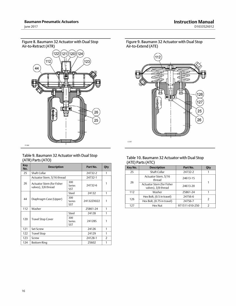
Figure 8. Baumann 32 Actuator with Dual Stop Air-to-Retract (ATR)
E1306
Table 9. Baumann 32 Actuator with Dual Stop (ATR) Parts (ATO)KeyNo.
Description Part No. Qty
25 Shaft Collar 24732-2 1
26
Actuator Stem, 5/16 thread 24732-1
1Actuator Stem (for Fishervalves), 3/8 thread
300
Series
SST24732-6
44 Diaphragm Case (Upper)
Steel 24132 1
300
Series
SST24132ZX022 1
112 Washer 25861-24 1
120 Travel Stop Cover
Steel 24128 1
300
Series
SST24128S 1
121 Set Screw 24126 1
122 Travel Stop 24129 1
123 Screw 24128-1 2
124 Bottom Ring 25602 1
Figure 9. Baumann 32 Actuator with Dual Stop Air-to-Extend (ATE)
E1307
Table 10. Baumann 32 Actuator with Dual Stop (ATE) Parts (ATC)Key No. Description Part No. Qty
25 Shaft Collar 24732-2 1
26
Actuator Stem, 5/16thread
24613-15
1Actuator Stem (for Fisher
valves), 3/8 thread24613-20
112 Washer 25861-24 1
126Hex Bolt, (0.5 in travel) 24756-6
2Hex Bolt, (0.75 in travel) 24756-7
127 Hex Nut 971511-010-250 2
Instruction ManualD103352X012
Baumann Pneumatic ActuatorsJune 2017
17
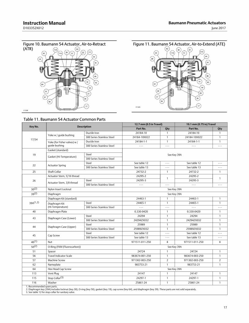
Figure 10. Baumann 54 Actuator, Air-to-Retract(ATR)
E1308
Figure 11. Baumann 54 Actuator, Air-to-Extend (ATE)
E1309
Table 11. Baumann 54 Actuator Common Parts
Key No. Description12.7 mm (0.5 in Travel) 19.1 mm (0.75 in) Travel
Part No. Qty Part No. Qty
17/54
Yoke w / guide bushingDuctile Iron 24184-10 1 24184-10 1
300 Series Stainless Steel 24184-10X022 1 24184-10X022 1
Yoke (for Fisher valves) w /guide bushing
Ductile Iron 24184-1-1 1 24184-1-1 1
300 Series Stainless Steel - - - - - - - - - - - -
19
Gasket (standard)
See Key 39AGasket (Hi-Temperature)
Steel
300 Series Stainless Steel
22 Actuator SpringSteel See table 12 - - - See table 12 - - -
300 Series Stainless Steel See table 13 - - - See table 13 - - -
25 Shaft Collar 24732-2 1 24732-2 1
26
Actuator Stem, 5/16 thread 24295-21
24295-21
Actuator Stem, 3/8 threadSteel 24295-3 24295-3
300 Series Stainless Steel - - - - - - - - - - - -
30(2) Nylon Insert Locknut See Key 39A
39(2) Diaphragm See Key 39A
39A(1,2)
Diaphragm Kit (standard) 24463-1 1 24463-1 1
Diaphragm Kit(Hi-Temperature)
Steel 24465-1 1 24465-1 1
300 Series Stainless Steel - - - - - - - - - - - -
40 Diaphragm Plate 0.330-0420 1 0.330-0420 1
43 Diaphragm Case (Lower)Steel 24294 1 24294 1
300 Series Stainless Steel 24294ZX032 1 24294ZX032 1
44 Diaphragm Case (Upper)Steel 25989 1 25989 1
300 Series Stainless Steel 25989ZX032 1 25989ZX032 1
45 Cap ScrewSteel See table 12 - - - See table 12 - - -
300 Series Stainless Steel See table 13 - - - See table 13 - - -
46(1) Nut 971511-011-250 8 971511-011-250 8
50(2) O-Ring (FKM (Fluorocarbon)) See Key 39A
51 Spacer 24724 1 24724 1
56 Travel Indicator Scale 983674-001-250 1 983674-003-250 1
57 Machine Screw 971302-003-250 2 971302-003-250 2
62 Nameplate 983753-21 1 983753-21 1
64 Hex Head Cap Screw See Key 39A
113 Vent Plug 24147 1 24147 1
115 Stop Collar(3) 24297-1 1 24297-1 1
116 Washer 25861-24 1 25861-24 1
1. Recommended spare parts.2. Diaphragm key (39A) includes locknut (key 30), O-ring (key 50), gasket (key 19), cap screw (key 64), and diaphragm (key 39). These parts are not sold separately.3. See table 12 for stop collar for sanitary valve.
Instruction ManualD103352X012
Baumann Pneumatic ActuatorsJune 2017
18
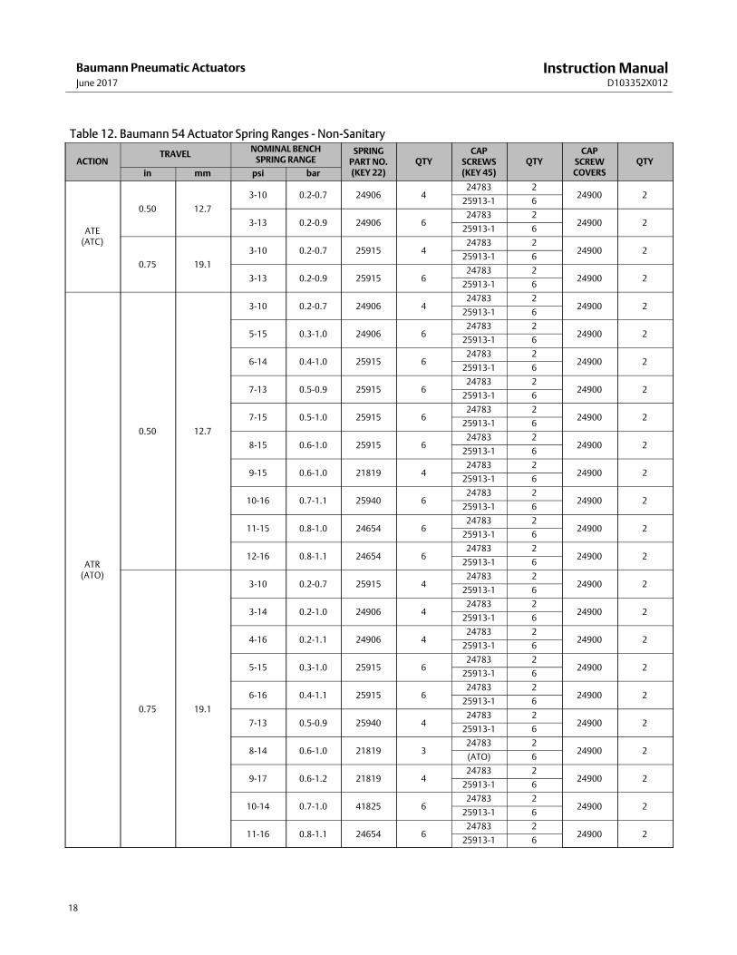
Table 12. Baumann 54 Actuator Spring Ranges - Non-Sanitary
ACTIONTRAVEL
NOMINAL BENCHSPRING RANGE
SPRINGPART NO.(KEY 22)
QTYCAP
SCREWS(KEY 45)
QTYCAP
SCREWCOVERS
QTY
in mm psi bar
ATE(ATC)
0.50 12.7
3-10 0.2-0.7 24906 424783 2
24900 225913-1 6
3-13 0.2-0.9 24906 624783 2
24900 225913-1 6
0.75 19.1
3-10 0.2-0.7 25915 424783 2
24900 225913-1 6
3-13 0.2-0.9 25915 624783 2
24900 225913-1 6
ATR(ATO)
0.50 12.7
3-10 0.2-0.7 24906 424783 2
24900 225913-1 6
5-15 0.3-1.0 24906 624783 2
24900 225913-1 6
6-14 0.4-1.0 25915 624783 2
24900 225913-1 6
7-13 0.5-0.9 25915 624783 2
24900 225913-1 6
7-15 0.5-1.0 25915 624783 2
24900 225913-1 6
8-15 0.6-1.0 25915 624783 2
24900 225913-1 6
9-15 0.6-1.0 21819 424783 2
24900 225913-1 6
10-16 0.7-1.1 25940 624783 2
24900 225913-1 6
11-15 0.8-1.0 24654 624783 2
24900 225913-1 6
12-16 0.8-1.1 24654 624783 2
24900 225913-1 6
0.75 19.1
3-10 0.2-0.7 25915 424783 2
24900 225913-1 6
3-14 0.2-1.0 24906 424783 2
24900 225913-1 6
4-16 0.2-1.1 24906 424783 2
24900 225913-1 6
5-15 0.3-1.0 25915 624783 2
24900 225913-1 6
6-16 0.4-1.1 25915 624783 2
24900 225913-1 6
7-13 0.5-0.9 25940 424783 2
24900 225913-1 6
8-14 0.6-1.0 21819 324783 2
24900 2(ATO) 6
9-17 0.6-1.2 21819 424783 2
24900 225913-1 6
10-14 0.7-1.0 41825 624783 2
24900 225913-1 6
11-16 0.8-1.1 24654 624783 2
24900 225913-1 6
Instruction ManualD103352X012
Baumann Pneumatic ActuatorsJune 2017
19
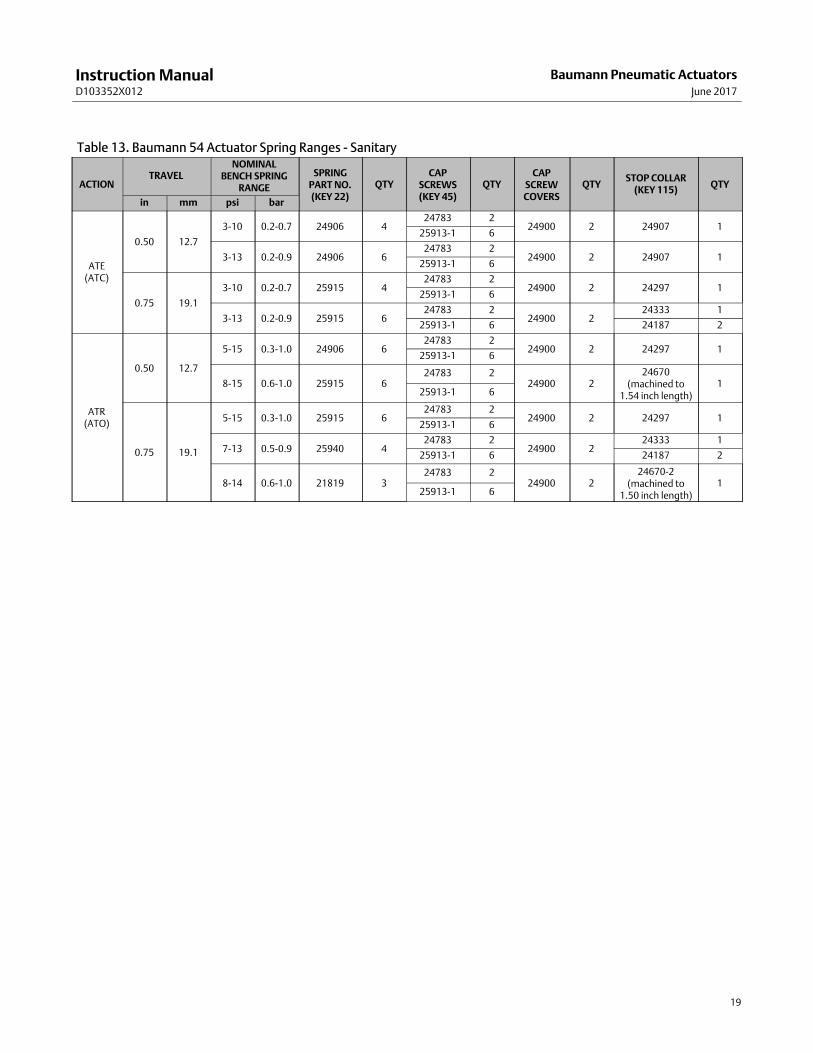
Table 13. Baumann 54 Actuator Spring Ranges - Sanitary
ACTIONTRAVEL
NOMINALBENCH SPRING
RANGE
SPRINGPART NO.(KEY 22)
QTYCAP
SCREWS(KEY 45)
QTYCAP
SCREWCOVERS
QTYSTOP COLLAR
(KEY 115)QTY
in mm psi bar
ATE(ATC)
0.50 12.7
3-10 0.2-0.7 24906 424783 2
24900 2 24907 125913-1 6
3-13 0.2-0.9 24906 624783 2
24900 2 24907 125913-1 6
0.75 19.1
3-10 0.2-0.7 25915 424783 2
24900 2 24297 125913-1 6
3-13 0.2-0.9 25915 624783 2
24900 224333 1
25913-1 6 24187 2
ATR(ATO)
0.50 12.7
5-15 0.3-1.0 24906 624783 2
24900 2 24297 125913-1 6
8-15 0.6-1.0 25915 624783 2
24900 224670
(machined to1.54 inch length)
125913-1 6
0.75 19.1
5-15 0.3-1.0 25915 624783 2
24900 2 24297 125913-1 6
7-13 0.5-0.9 25940 424783 2
24900 224333 1
25913-1 6 24187 2
8-14 0.6-1.0 21819 324783 2
24900 224670-2
(machined to1.50 inch length)
125913-1 6
Instruction ManualD103352X012
Baumann Pneumatic ActuatorsJune 2017
20
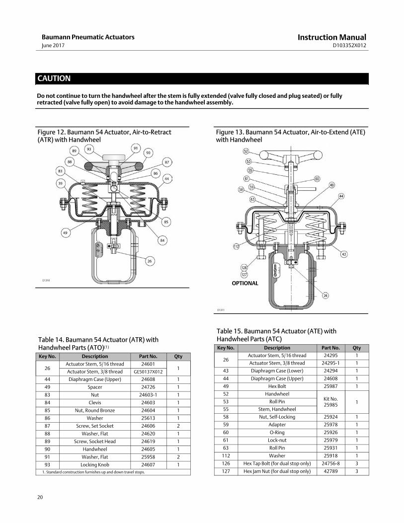
CAUTION
Do not continue to turn the handwheel after the stem is fully extended (valve fully closed and plug seated) or fullyretracted (valve fully open) to avoid damage to the handwheel assembly.
Figure 12. Baumann 54 Actuator, Air-to-Retract(ATR) with Handwheel
E1310
Table 14. Baumann 54 Actuator (ATR) with Handwheel Parts (ATO)(1)
Key No. Description Part No. Qty
26Actuator Stem, 5/16 thread 24601
1Actuator Stem, 3/8 thread GE50137X012
44 Diaphragm Case (Upper) 24608 1
49 Spacer 24726 1
83 Nut 24603-1 1
84 Clevis 24603 1
85 Nut, Round Bronze 24604 1
86 Washer 25613 1
87 Screw, Set Socket 24606 2
88 Washer, Flat 24620 1
89 Screw, Socket Head 24619 1
90 Handwheel 24605 1
91 Washer, Flat 25958 2
93 Locking Knob 24607 1
1. Standard construction furnishes up and down travel stops.
E1311
OPTIONAL
Figure 13. Baumann 54 Actuator, Air-to-Extend (ATE)with Handwheel
Table 15. Baumann 54 Actuator (ATE) with Handwheel Parts (ATC)Key No. Description Part No. Qty
26Actuator Stem, 5/16 thread 24295 1
Actuator Stem, 3/8 thread 24295-1 1
43 Diaphragm Case (Lower) 24294 1
44 Diaphragm Case (Upper) 24608 1
49 Hex Bolt 25987 1
52 HandwheelKit No.25985
153 Roll Pin
55 Stem, Handwheel
58 Nut, Self-Locking 25924 1
59 Adapter 25978 1
60 O-Ring 25926 1
61 Lock-nut 25979 1
63 Roll Pin 25931 1
112 Washer 25918 1
126 Hex Tap Bolt (for dual stop only) 24756-8 3
127 Hex Jam Nut (for dual stop only) 42789 3
Instruction ManualD103352X012
Baumann Pneumatic ActuatorsJune 2017
21
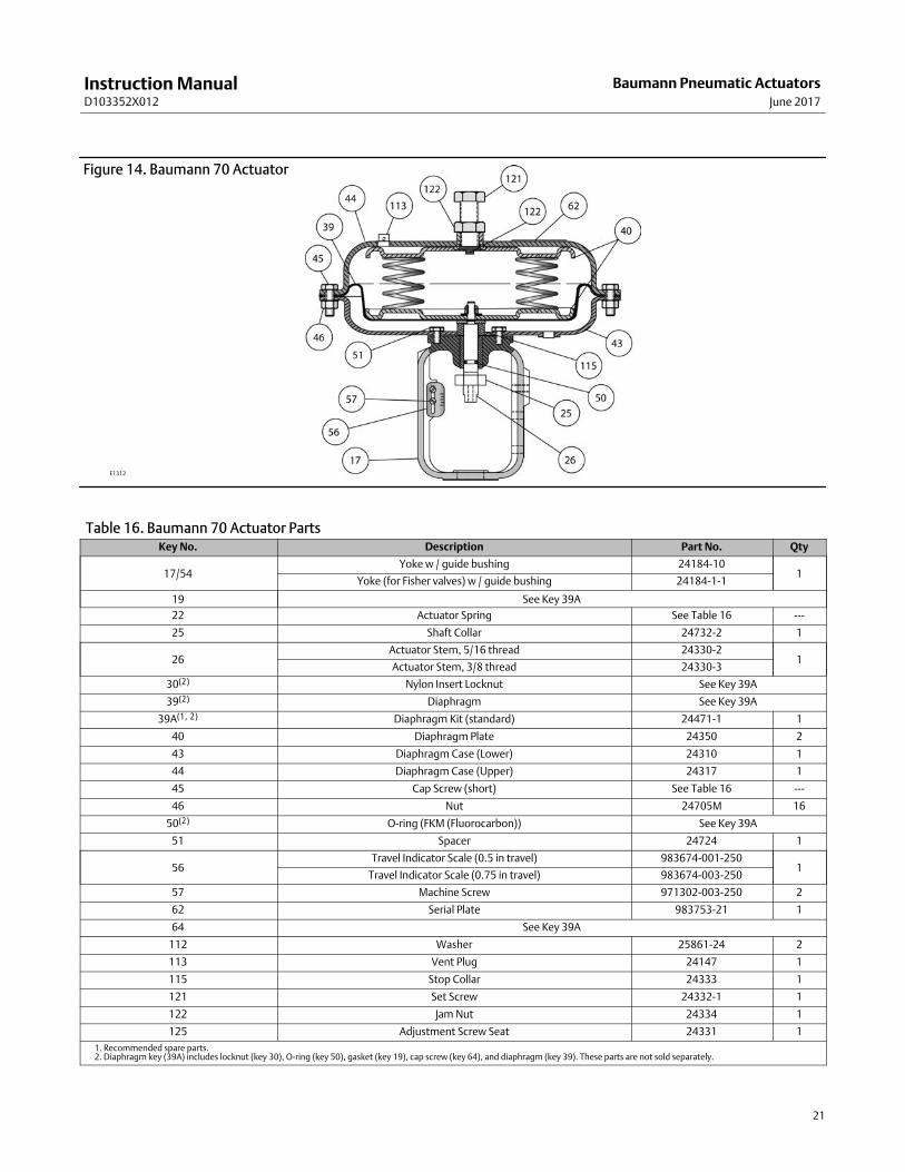
Figure 14. Baumann 70 Actuator
E1312
Table 16. Baumann 70 Actuator PartsKey No. Description Part No. Qty
17/54Yoke w / guide bushing 24184-10
1Yoke (for Fisher valves) w / guide bushing 24184-1-1
19 See Key 39A
22 Actuator Spring See Table 16 ---
25 Shaft Collar 24732-2 1
26Actuator Stem, 5/16 thread 24330-2
1Actuator Stem, 3/8 thread 24330-3
30(2) Nylon Insert Locknut See Key 39A
39(2) Diaphragm See Key 39A
39A(1, 2) Diaphragm Kit (standard) 24471-1 1
40 Diaphragm Plate 24350 2
43 Diaphragm Case (Lower) 24310 1
44 Diaphragm Case (Upper) 24317 1
45 Cap Screw (short) See Table 16 ---
46 Nut 24705M 16
50(2) O-ring (FKM (Fluorocarbon)) See Key 39A
51 Spacer 24724 1
56Travel Indicator Scale (0.5 in travel) 983674-001-250
1Travel Indicator Scale (0.75 in travel) 983674-003-250
57 Machine Screw 971302-003-250 2
62 Serial Plate 983753-21 1
64 See Key 39A
112 Washer 25861-24 2
113 Vent Plug 24147 1
115 Stop Collar 24333 1
121 Set Screw 24332-1 1
122 Jam Nut 24334 1
125 Adjustment Screw Seat 24331 1
1. Recommended spare parts.2. Diaphragm key (39A) includes locknut (key 30), O-ring (key 50), gasket (key 19), cap screw (key 64), and diaphragm (key 39). These parts are not sold separately.
Instruction ManualD103352X012
Baumann Pneumatic ActuatorsJune 2017
22
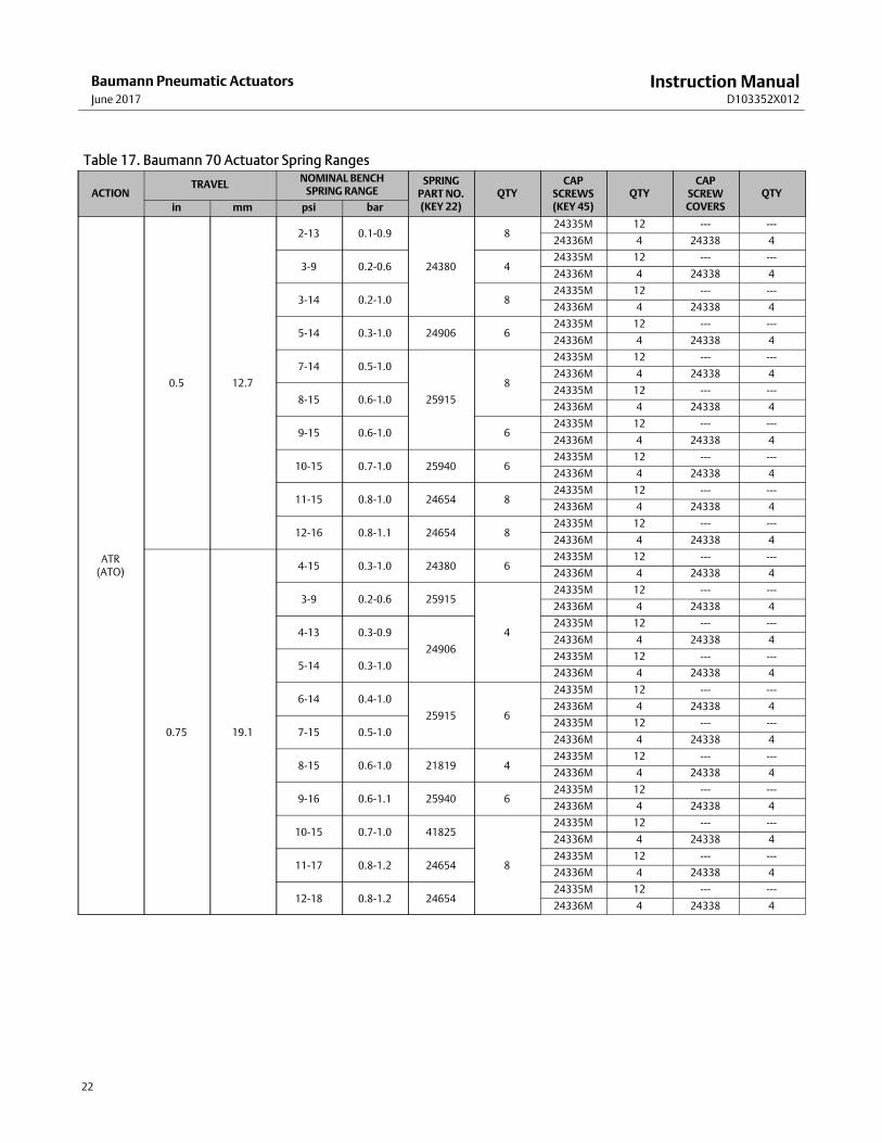
Table 17. Baumann 70 Actuator Spring Ranges
ACTIONTRAVEL
NOMINAL BENCHSPRING RANGE
SPRINGPART NO.(KEY 22)
QTYCAP
SCREWS(KEY 45)
QTYCAP
SCREWCOVERS
QTY
in mm psi bar
ATR(ATO)
0.5 12.7
2-13 0.1-0.9
24380
824335M 12 --- ---
24336M 4 24338 4
3-9 0.2-0.6 424335M 12 --- ---
24336M 4 24338 4
3-14 0.2-1.0 824335M 12 --- ---
24336M 4 24338 4
5-14 0.3-1.0 24906 624335M 12 --- ---
24336M 4 24338 4
7-14 0.5-1.0
25915
8
24335M 12 --- ---
24336M 4 24338 4
8-15 0.6-1.024335M 12 --- ---
24336M 4 24338 4
9-15 0.6-1.0 624335M 12 --- ---
24336M 4 24338 4
10-15 0.7-1.0 25940 624335M 12 --- ---
24336M 4 24338 4
11-15 0.8-1.0 24654 824335M 12 --- ---
24336M 4 24338 4
12-16 0.8-1.1 24654 824335M 12 --- ---
24336M 4 24338 4
0.75 19.1
4-15 0.3-1.0 24380 624335M 12 --- ---
24336M 4 24338 4
3-9 0.2-0.6 25915
4
24335M 12 --- ---
24336M 4 24338 4
4-13 0.3-0.9
24906
24335M 12 --- ---
24336M 4 24338 4
5-14 0.3-1.024335M 12 --- ---
24336M 4 24338 4
6-14 0.4-1.0
25915 6
24335M 12 --- ---
24336M 4 24338 4
7-15 0.5-1.024335M 12 --- ---
24336M 4 24338 4
8-15 0.6-1.0 21819 424335M 12 --- ---
24336M 4 24338 4
9-16 0.6-1.1 25940 624335M 12 --- ---
24336M 4 24338 4
10-15 0.7-1.0 41825
8
24335M 12 --- ---
24336M 4 24338 4
11-17 0.8-1.2 2465424335M 12 --- ---
24336M 4 24338 4
12-18 0.8-1.2 2465424335M 12 --- ---
24336M 4 24338 4
Instruction ManualD103352X012
Baumann Pneumatic ActuatorsJune 2017
23
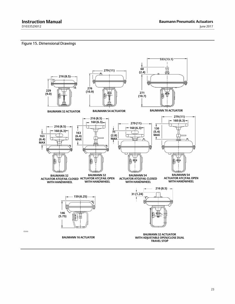
Figure 15. Dimensional Drawings
E1313
229(9.0)
BAUMANN 32 ACTUATOR
276(10.9) 271
(10.7)
60(2.4)
163(6.4)MAX
163(6.4)MAX
71(2.8)MAX
130(5.4)MAX
146(5.75)
159 (6.25)31 (1.24)
216 (8.5)
216 (8.5)
160 (6.3)
216 (8.5)
160 (6.3)
160 (6.3)
160 (6.3)279 (11)
279 (11)
216 (8.5)
279 (11)
333 (13.1)
BAUMANN 54 ACTUATOR BAUMANN 70 ACTUATOR
BAUMANN 32 ACTUATOR ATO/FAIL CLOSED
WITH HANDWHEEL
BAUMANN 32 ACTUATOR ATC/FAIL OPEN
WITH HANDWHEEL
BAUMANN 54 ACTUATOR ATO/FAIL CLOSED
WITH HANDWHEEL
BAUMANN 54 ACTUATOR ATC/FAIL OPEN
WITH HANDWHEEL
BAUMANN 16 ACTUATORBAUMANN 32 ACTUATOR
WITH ADJUSTABLE OPEN/CLOSE DUALTRAVEL STOP
Instruction ManualD103352X012
Baumann Pneumatic ActuatorsJune 2017
24
Parts OrderingWhen corresponding with your Emerson sales office or Local Business Partner about this equipment, always mentionthe valve serial number. When ordering replacement parts, also specify the key number, part name, and desiredmaterial using the Parts List table.
WARNING
Use only genuine Fisher replacement parts. Components that are not supplied by Emerson Automation Solutions shouldnot, under any circumstances, be used in any Fisher valve, because they may void your warranty, might adversely affect theperformance of the valve and actuator, and could cause personal injury and property damage.
Emerson Automation Solutions Marshalltown, Iowa 50158 USASorocaba, 18087 BrazilCernay 68700 FranceDubai, United Arab EmiratesSingapore 128461 Singapore
www.Fisher.com
The contents of this publication are presented for informational purposes only, and while every effort has been made to ensure their accuracy, they are notto be construed as warranties or guarantees, express or implied, regarding the products or services described herein or their use or applicability. All sales aregoverned by our terms and conditions, which are available upon request. We reserve the right to modify or improve the designs or specifications of suchproducts at any time without notice.
� 2009, 2017 Fisher Controls International LLC. All rights reserved.
Baumann and Fisher are marks owned by one of the companies in the Emerson Automation Solutions business unit of Emerson Electric Co. EmersonAutomation Solutions, Emerson, and the Emerson logo are trademarks and service marks of Emerson Electric Co. All other marks are the property of theirrespective owners.
Neither Emerson, Emerson Automation Solutions, nor any of their affiliated entities assumes responsibility for the selection, use or maintenanceof any product. Responsibility for proper selection, use, and maintenance of any product remains solely with the purchaser and end user.