battery accommodation - enersys
TRANSCRIPT
RESERVEPOWER
BatteryAccommodation
Steel Stands 2
Constructional &
Component Details 2
Stand Dimensions, Sizing
Method & Examples 3-5
a) PowerSafe® V
b) PowerSafe® VFront Terminal
Electrical Connections 6
a) Single Series Battery onSingle Row Stand
b) Single Series Battery onDouble Row Stand
c) Series Parallel Batteries
d) Transition Boxes
Battery Room Layout 7-9
a) Height
b) Width
c) Length
d) Examples
PowerSafe® V
General Specifications 10
Steel StandsContents
A comprehensive range of steelstands has been specificallydesigned to provide a compact andeffective arrangement forPowerSafe® V batteries whilstretaining the requirements ofelectrical and mechanical safety,ease of installation and accessduring operation for taking meterreadings.
Steel stands are available as freestanding units (complete withadjustable insulating feet), anti-shock units (for offshore or
unpredictable environments) orseismic units (for areas of geologicalunpredictability or sites such asnuclear power stations). Each standtype is configured to provideoptimum access for both installationand maintenance and suppliedcomplete with accessories for wallor floor fixing and attachment ofancillary equipment.
Cabinets and other special designscan be engineered and supplied tomeet particular specifications.
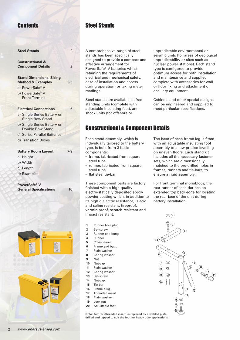
Constructional & Component Details
Each stand assembly, which isindividually tailored to the batterytype, is built from 3 basiccomponents:• frame, fabricated from square
steel tube• runner, fabricated from square
steel tube• flat steel tie-bar
These component parts are factoryfinished with a high qualityelectro-statically deposited epoxypowder coating which, in addition toits high dielectric resistance, is acidand saline resistant, fireproof,vermin proof, scratch resistant andimpact resistant.
The base of each frame leg is fittedwith an adjustable insulating footassembly to allow precise levellingon uneven floors. Each stand kitincludes all the necessary fastenersets, which are dimensionallymatched to the pre-drilled holes inframes, runners and tie-bars, toensure a rigid assembly.
For front terminal monoblocs, therear runner of each tier has anextended top back edge for locatingthe rear face of the unit duringbattery installation.
2 www.enersys-emea.com
1 Runner hole plug2 Set-screw3 Runner end bung4 Runner5 Crossbearer6 Frame end bung7 Plain washer8 Spring washer9 Nut10 Nut-cap11 Plain washer12 Spring washer13 Set-screw14 Nut-cap15 Tie-bar16 Frame plug17 Threaded insert18 Plain washer19 Lock-nut20 Adjustable foot
14
11
12
13
7
8
9
10
1
2
3
4
5 6
1516
17
18
19
20
Note: Item 17 (threaded insert) is replaced by a welded platedrilled and tapped to suit the foot for heavy duty applications.
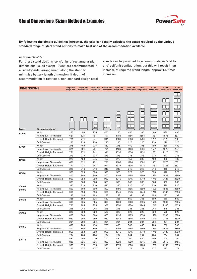
Stand Dimensions, Sizing Method & Examples
a) PowerSafe® V
For these stand designs, cells/units of rectangular plandimensions (ie. all except 12V80) are accommodated ina 'side-by-side' arrangement along the stand tominimise battery length dimension. If depth ofaccommodation is restricted, non-standard design steel
stands can be provided to accommodate an 'end toend' cell/unit configuration, but this will result in anincrease of required stand length (approx 1.5 timesincrease).
By following the simple guidelines hereafter, the user can readily calculate the space required by the various
standard range of steel stand options to make best use of the accommodation available.
Single Tier Single Tier Double Tier Double Tier Triple Tier Triple Tier 4 Tier 4 Tier 5 Tier 6 TierSingle Row Double Row Single Row Double Row Single Row Double Row Single Row Double Row Double Row Double RowDIMENSIONS
3www.enersys-emea.com
Types Dimensions (mm)
Width 275 450 275 450 275 450 305 480 480 480Height over Terminals 621 621 791 791 1186 1186 1581 1581 1976 2371Overall Height Required 771 771 941 941 1336 1336 1731 1731 2126 2521Cell Centres 220 220 220 220 220 220 220 220 220 220Width 275 450 275 450 275 450 305 480 480 480Height over Terminals 621 621 791 791 1186 1186 1581 1581 1976 2371Overall Height Required 771 771 941 941 1336 1336 1731 1731 2126 2521Cell Centres 273 273 273 273 273 273 273 273 273 273Width 275 450 275 450 275 450 305 480 480 480Height over Terminals 621 621 791 791 1186 1186 1581 1581 1976 2371Overall Height Required 771 771 941 941 1336 1336 1731 1731 2126 2521Cell Centres 316 316 316 316 316 316 316 316 316 316Width 320 520 320 520 320 520 320 520 520 520Height over Terminals 800 800 800 800 1195 1195 1590 1590 1985 2380Overall Height Required 950 950 950 950 1345 1345 1740 1740 2135 2530Cell Centres 368 368 368 368 368 368 368 368 368 368Width 320 520 320 520 320 520 320 520 520 520Height over Terminals 800 800 800 800 1195 1195 1590 1590 1985 2380Overall Height Required 950 950 950 950 1345 1345 1740 1740 2135 2530Cell Centres 193 193 193 193 193 193 193 193 193 193Width 325 550 325 550 325 550 355 580 580 580Height over Terminals 635 635 805 805 1200 1200 1595 1595 1990 2385Overall Height Required 785 785 955 955 1350 1350 1745 1745 2140 2535Cell Centres 245 245 245 245 245 245 245 245 245 245Width 320 520 320 520 320 520 320 520 520 520Height over Terminals 800 800 800 800 1195 1195 1590 1590 1985 2380Overall Height Required 950 950 950 950 1345 1345 1740 1740 2135 2530Cell Centres 204 204 204 204 204 204 204 204 204 204Width 430 700 430 700 430 700 430 700 700 700Height over Terminals 800 800 800 800 1195 1195 1590 1590 1985 2380Overall Height Required 950 950 950 950 1345 1345 1740 1740 2135 2530Cell Centres 204 204 204 204 204 204 204 204 204 204Width 430 700 430 700 430 700 430 700 700 700Height over Terminals 825 825 825 825 1220 1220 1615 1615 2010 2405Overall Height Required 975 975 975 975 1370 1370 1765 1765 2160 2555Cell Centres 177 177 177 177 177 177 177 177 177 177
12V45
12V55
12V70
12V80
4V105
6V105
6V130
4V155
6V170
6V155
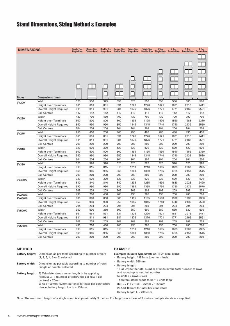
Stand Dimensions, Sizing Method & Examples
Types Dimensions (mm)
Width 325 550 325 550 325 550 355 580 580 580Height over Terminals 661 661 831 831 1226 1226 1621 1621 2016 2411Overall Height Required 811 811 981 981 1376 1376 1771 1771 2166 2561Cell Centres 112 112 112 112 112 112 112 112 112 112Width 430 700 430 700 430 700 430 700 700 700Height over Terminals 800 800 800 800 1195 1195 1590 1590 1985 2380Overall Height Required 950 950 950 950 1345 1345 1740 1740 2135 2530Cell Centres 204 204 204 204 204 204 204 204 204 204Width 250 400 250 400 250 400 280 430 430 430Height over Terminals 661 661 831 831 1226 1226 1621 1621 2016 2411Overall Height Required 811 811 981 981 1376 1376 1771 1771 2166 2561Cell Centres 209 209 209 209 209 209 209 209 209 209Width 320 520 320 520 320 520 320 520 520 520Height over Terminals 800 800 800 800 1195 1195 1590 1590 1985 2380Overall Height Required 950 950 950 950 1345 1345 1740 1740 2135 2530Cell Centres 204 204 204 204 204 204 204 204 204 204Width 320 520 320 520 320 520 320 520 520 520Height over Terminals 815 815 815 815 1210 1210 1605 1605 2000 2395Overall Height Required 965 965 965 965 1360 1360 1755 1755 2150 2545Cell Centres 209 209 209 209 209 209 209 209 209 209Width 320 520 320 520 320 520 320 520 520 520Height over Terminals 840 840 840 840 1235 1235 1630 1630 2025 2420Overall Height Required 990 990 990 990 1385 1385 1780 1780 2175 2570Cell Centres 209 209 209 209 209 209 209 209 209 209Width 430 700 430 700 430 700 430 700 700 700Height over Terminals 800 800 800 800 1195 1195 1590 1590 1985 2380Overall Height Required 950 950 950 950 1345 1345 1740 1740 2135 2530Cell Centres 204 204 204 204 204 204 204 204 204 204Width 350 600 350 600 350 600 380 630 630 630Height over Terminals 661 661 831 831 1226 1226 1621 1621 2016 2411Overall Height Required 811 811 981 981 1376 1376 1771 1771 2166 2561Cell Centres 209 209 209 209 209 209 209 209 209 209Width 430 700 430 700 430 700 430 700 700 700Height over Terminals 815 815 815 815 1210 1210 1605 1605 2000 2395Overall Height Required 965 965 965 965 1360 1360 1755 1755 2150 2545Cell Centres 209 209 209 209 209 209 209 209 209 209
Single Tier Single Tier Double Tier Double Tier Triple Tier Triple Tier 4 Tier 4 Tier 5 Tier 6 TierSingle Row Double Row Single Row Double Row Single Row Double Row Single Row Double Row Double Row Double Row
2V200
4V230
2V275
2V310
2V460/42V460/6
2V400/2
2V320
DIMENSIONS
2V500/2
2V500/6
METHOD
Battery height: Dimension as per table according to number of tiers(1, 2, 3, 4, 5 or 6) selected
Battery width: Dimension as per table according to number of rows(single or double) selected
Battery length: 1) Calculate stand runner length L1 by applying formula L1 = (number of cells/units per row x cellcentres) + 25mm2) Add 100mm (50mm per end) for inter-tier connectorsHence, battery length L = L1 + 100mm
EXAMPLE
Example: 56 units type 6V105 on TTDR steel stand
- Battery height: 1195mm (over terminals)- Battery width: 520mm- Battery length:
1) (a) Divide the total number of units by the total number of rowsand round up to next full number56 units / 6 rows = 9.33Therefore stand needs to be '10 units long'(b) L1 = (10 x 193) + 25mm = 1955mm2) Add 100mm for inter-tier connectorsBattery length L = 2055mm
4 www.enersys-emea.com
Note: The maximum length of a single stand is approximately 3 metres. For lengths in excess of 3 metres multiple stands are supplied.
Types Dimensions (mm)
Width 450 450 450 455 455 455Height 335 585 835 1085 1335 1585Unit Centres 107 107 107 107 107 107Width 450 450 450 455 455 455Height 360 635 910 1185 1460 1735Unit Centres 107 107 107 107 107 107Width 450 450 450 455 455 455Height 440 790 1140 1490 1840 2190Unit Centres 107 107 107 107 107 107Width 550 550 550 555 555 555Height 440 800 1160 1520 1880 2240Unit Centres 115 115 115 115 115 115Width 550 550 550 555 555 555Height 463 838 1213 1588 1963 2338Unit Centres 118 118 118 118 118 118Width 700 700 700 705 705 705Height 411 786 1161 1536 1911 2286Unit Centres 120 120 120 120 120 120Width 750 750 750 755 755 755Height 492 892 1292 1692 2092 2492Unit Centres 115 115 115 115 115 115Width 750 750 750 755 755 755Height 459 834 1209 1584 1959 2334Unit Centres 135 135 135 135 135 135Width 750 750 750 755 755 755Height 459 834 1209 1584 1959 2334Unit Centres 135 135 135 135 135 135Width 750 750 750 755 755 755Height 492 892 1292 1692 2092 2492Unit Centres 135 135 135 135 135 135Width 750 750 750 755 755 755Height 492 892 1292 1692 2092 2492Unit Centres 135 135 135 135 135 135
Stand Dimensions, Sizing Method & Examples
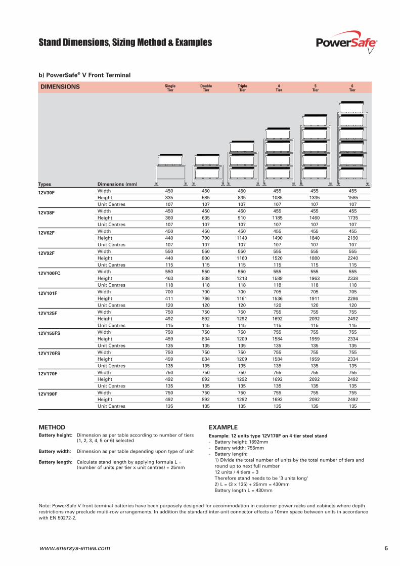
b) PowerSafe® V Front Terminal
Single Double Triple 4 5 6Tier Tier Tier Tier Tier Tier
12V30F
12V38F
12V62F
12V92F
METHOD
Battery height: Dimension as per table according to number of tiers(1, 2, 3, 4, 5 or 6) selected
Battery width: Dimension as per table depending upon type of unit
Battery length: Calculate stand length by applying formula L =(number of units per tier x unit centres) + 25mm
EXAMPLE
Example: 12 units type 12V170F on 4 tier steel stand
- Battery height: 1692mm- Battery width: 755mm- Battery length:
1) Divide the total number of units by the total number of tiers andround up to next full number12 units / 4 tiers = 3Therefore stand needs to be '3 units long'2) L = (3 x 135) + 25mm = 430mmBattery length L = 430mm
12V100FC
DIMENSIONS
5www.enersys-emea.com
Note: PowerSafe V front terminal batteries have been purposely designed for accommodation in customer power racks and cabinets where depthrestrictions may preclude multi-row arrangements. In addition the standard inter-unit connector effects a 10mm space between units in accordancewith EN 50272-2.
12V170F
12V190F
12V170FS
12V101F
12V125F
12V155FS

Electrical Connections
Where batteries are ordered complete with stands, all
necessary inter-cell/unit connectors (including insulated
inter-row and inter-tier connectors, depending upon
battery type) are provided.
The following general notes indicate the standard
methods employed for the electrical connection
sequence within the battery and the resulting battery
terminal position.
a) Single Series Battery on Single Row Stand
The series connector run is along the length of the
stand and then, in the case of multi-tier stand vertically
down, via inter-tier connector, to the next tier such that
main battery terminals are located:
• at opposite ends of the stand for odd numbers of tiers
or
• at the same end of the stand for an even number of
tiers
b) Single Series Battery on Double Row Stand
The series connector run is along the length of the
stand on back (or front) row then horizontal across to
front (or back) row via the inter-row connector and back
towards starting point end of the stand.
In the case of a multi-tier stand, the connection
sequence is continued vertically down via the inter-tier
connector and maintained by connecting along the row
to the opposite end of the stand, followed by horizontal
across row connection as the previous tier, such that
the main battery terminals are at the same end of the
stand irrespective of the number of tiers.
c) Series Parallel Batteries
It is normal practice to effect the electrical paralleling
via the battery terminals as opposed to paralleling of
individual cells. Therefore, where each series battery
circuit is accommodated on its own stand and the
parallel connection is made at a common bus bar point,
the notes contained in a) and b) above are applicable.
However, where it is desirable to accommodate the
total series parallel battery on the same stand, in order
to effect a practical connection arrangement, it is
essential that the stand design chosen not only
matches the number of parallel strings involved (3
parallel strings on a single tier, double tier, 4 tier or 5
tier stand, would be impractical) but allows the main
battery terminals to be suitably positioned to
correspond with the desired locations of bus bars.
d) Transition Boxes
Transition boxes are also available to connect the
battery main end leads (separate boxes for positive and
negative) to outgoing cables or bus bars. Where
necessary, it also affords a safe and convenient method
of paralleling banks of cells. Transition boxes come
complete with mounting plates and connectors.
Customers not using transition boxes should ensure
that connections to the battery end terminals are well
supported to avoid stress on the pillar seals.
Closure plates (Top & Bottom)to be cut/drilled to suitincoming/outgoingconnections
Transition Box mounting bracketCat No SRH1567 (700 wide stand)SRH1568 (520 wide stand)
Battery stand
Transition Box AssemblyCat No SRF0277(2 required per battery)
6 www.enersys-emea.com
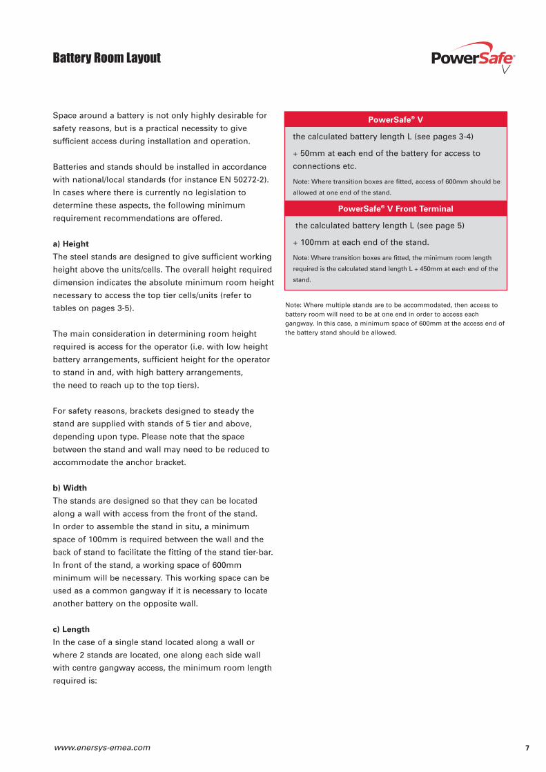
Space around a battery is not only highly desirable for
safety reasons, but is a practical necessity to give
sufficient access during installation and operation.
Batteries and stands should be installed in accordance
with national/local standards (for instance EN 50272-2).
In cases where there is currently no legislation to
determine these aspects, the following minimum
requirement recommendations are offered.
a) Height
The steel stands are designed to give sufficient working
height above the units/cells. The overall height required
dimension indicates the absolute minimum room height
necessary to access the top tier cells/units (refer to
tables on pages 3-5).
The main consideration in determining room height
required is access for the operator (i.e. with low height
battery arrangements, sufficient height for the operator
to stand in and, with high battery arrangements,
the need to reach up to the top tiers).
For safety reasons, brackets designed to steady the
stand are supplied with stands of 5 tier and above,
depending upon type. Please note that the space
between the stand and wall may need to be reduced to
accommodate the anchor bracket.
b) Width
The stands are designed so that they can be located
along a wall with access from the front of the stand.
In order to assemble the stand in situ, a minimum
space of 100mm is required between the wall and the
back of stand to facilitate the fitting of the stand tier-bar.
In front of the stand, a working space of 600mm
minimum will be necessary. This working space can be
used as a common gangway if it is necessary to locate
another battery on the opposite wall.
c) Length
In the case of a single stand located along a wall or
where 2 stands are located, one along each side wall
with centre gangway access, the minimum room length
required is:
Note: Where multiple stands are to be accommodated, then access tobattery room will need to be at one end in order to access eachgangway. In this case, a minimum space of 600mm at the access end ofthe battery stand should be allowed.
Battery Room Layout
7www.enersys-emea.com
PowerSafe® V
the calculated battery length L (see pages 3-4)
+ 50mm at each end of the battery for access to
connections etc.
Note: Where transition boxes are fitted, access of 600mm should be
allowed at one end of the stand.
PowerSafe® V Front Terminal
the calculated battery length L (see page 5)
+ 100mm at each end of the stand.
Note: Where transition boxes are fitted, the minimum room length
required is the calculated stand length L + 450mm at each end of the
stand.
Battery Room Layout
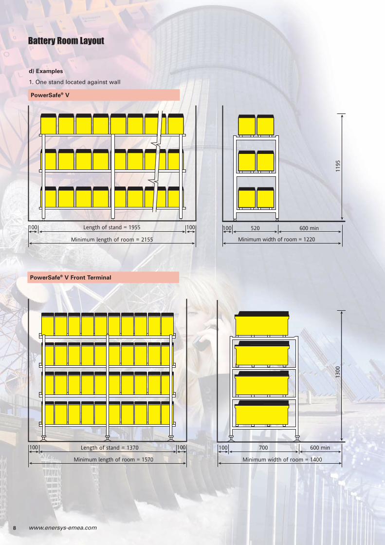
d) Examples
1. One stand located against wall
PowerSafe® V
Minimum length of room = 2155
Length of stand = 1955 100100 520100
Minimum width of room = 1220
600 min
1195
Minimum length of room = 1570
Length of stand = 1370 700100
Minimum width of room = 1400
600 min
1300
100 100
PowerSafe® V Front Terminal
8 www.enersys-emea.com
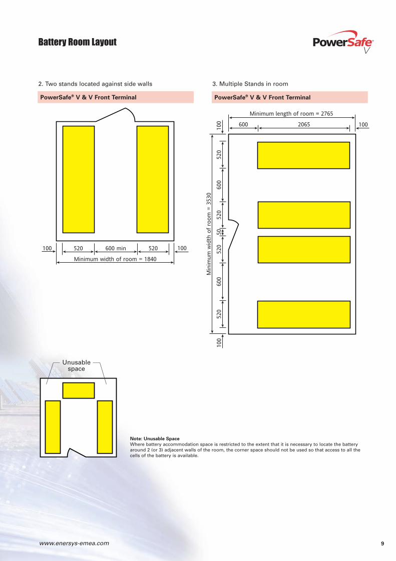
PowerSafe® V & V Front Terminal
2. Two stands located against side walls 3. Multiple Stands in room
PowerSafe® V & V Front Terminal
Battery Room Layout
Minimum width of room = 1840
600 min520100 520 100
Min
imum
wid
th o
f ro
om
= 35
30
600
520
520
5052
060
052
010
0
Minimum length of room = 2765
600 2065 100
100
Note: Unusable Space
Where battery accommodation space is restricted to the extent that it is necessary to locate the batteryaround 2 (or 3) adjacent walls of the room, the corner space should not be used so that access to all thecells of the battery is available.
Unusablespace
9www.enersys-emea.com
10 www.enersys-emea.com
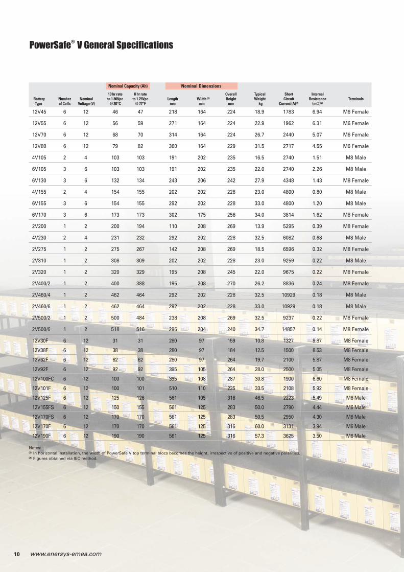
PowerSafe® V General Specifications
12V45 6 12 46 47 218 164 224 18.9 1783 6.94 M6 Female
12V55 6 12 56 59 271 164 224 22.9 1962 6.31 M6 Female
12V70 6 12 68 70 314 164 224 26.7 2440 5.07 M6 Female
12V80 6 12 79 82 360 164 229 31.5 2717 4.55 M6 Female
4V105 2 4 103 103 191 202 235 16.5 2740 1.51 M8 Male
6V105 3 6 103 103 191 202 235 22.0 2740 2.26 M8 Male
6V130 3 6 132 134 243 206 242 27.9 4348 1.43 M8 Female
4V155 2 4 154 155 202 202 228 23.0 4800 0.80 M8 Male
6V155 3 6 154 155 292 202 228 33.0 4800 1.20 M8 Male
6V170 3 6 173 173 302 175 256 34.0 3814 1.62 M8 Female
2V200 1 2 200 194 110 208 269 13.9 5295 0.39 M8 Female
4V230 2 4 231 232 292 202 228 32.5 6082 0.68 M8 Male
2V275 1 2 275 267 142 208 269 18.5 6596 0.32 M8 Female
2V310 1 2 308 309 202 202 228 23.0 9259 0.22 M8 Male
2V320 1 2 320 329 195 208 245 22.0 9675 0.22 M8 Female
2V400/2 1 2 400 388 195 208 270 26.2 8836 0.24 M8 Female
2V460/4 1 2 462 464 292 202 228 32.5 10929 0.18 M8 Male
2V460/6 1 2 462 464 292 202 228 33.0 10929 0.18 M8 Male
2V500/2 1 2 500 484 238 208 269 32.5 9237 0.22 M8 Female
2V500/6 1 2 518 516 296 204 240 34.7 14857 0.14 M8 Female
12V30F 6 12 31 31 280 97 159 10.8 1327 9.87 M8 Female
12V38F 6 12 38 38 280 97 184 12.5 1500 8.53 M8 Female
12V62F 6 12 62 62 280 97 264 19.7 2100 5.87 M8 Female
12V92F 6 12 92 92 395 105 264 28.0 2500 5.05 M8 Female
12V100FC 6 12 100 100 395 108 287 30.8 1900 6.60 M8 Female
12V101F 6 12 100 101 510 110 235 33.5 2108 5.92 M8 Female
12V125F 6 12 125 126 561 105 316 46.5 2223 5.49 M6 Male
12V155FS 6 12 150 155 561 125 283 50.0 2790 4.44 M6 Male
12V170FS 6 12 170 170 561 125 283 50.5 2950 4.30 M6 Male
12V170F 6 12 170 170 561 125 316 60.0 3131 3.94 M6 Male
12V190F 6 12 190 190 561 125 316 57.3 3625 3.50 M6 Male
Nominal Capacity (Ah) Nominal Dimensions
10 hr rate 8 hr rate Overall Typical Short InternalBattery Number Nominal to 1.80Vpc to 1.75Vpc Length Width (1) Height Weight Circuit Resistance TerminalsType of Cells Voltage (V) @ 20°C @ 77°F mm mm mm kg Current (A)(2) (mΩ)(2)
Notes:(1) In horizontal installation, the width of PowerSafe V top terminal blocs becomes the height, irrespective of positive and negative polarities. (2) Figures obtained via IEC method.

11www.enersys-emea.com
Notes
Publ
icat
ion
No.
EN
-V-B
A-0
05 -
Apr
il 20
11 -
Sub
ject
to
revi
sion
s w
ithou
t pr
ior
notic
e. E
.&O
.E.
www.enersys-emea.com
© 2011 EnerSys. All rights reserved.Trademarks and logos are the property of EnerSys and its
affiliates unless otherwise noted.
EnerSys
P.O. Box 14145Reading, PA 19612-4145USATel: +1-610-208-1991
+1-800-538-3627Fax: +1-610-372-8613
EnerSys Europe
Löwenstrasse 32 8001 ZurichSwitzerland
EnerSys Asia
152 Beach Road Gateway East BuildingLevel 11 189721 Singapore Tel. +65 6508 1780
EnerSys Ltd.
Oak CourtClifton Business ParkWynne AvenueSwintonManchester M27 8FFUKTel: +44 (0)161 794 4611Fax: +44 (0)161 727 3809
Contact: