barrington c incorporated onsultants ttm - barrington consultants inc
TRANSCRIPT
445 Laguna Vista Road Santa Rosa, CA 95401
Barrington
707/527-8254 Fax 707/542-9730 www.barringtoninc.com
Consultants Incorporated TTM
MODEL TTM
TRANSFORMER TEMPERATURE MONITOR AND COOLING CONTROL SYSTEM
BCI Bulletin BCI-TTM-01 Revision 12/03/02 CONTENTS Page
I. Description of Operation 2
Main menu & keypad 4 Configuration menu & lookback example 5 Displays: ambient temp, % stage loading, primary amps 3 Calibration displays 6 Cable interface & analog scaling values 6 Functional diagram 7 Configuration jumpers 8 Communications 9 Alarm LEDs 10 Hysteresis 10
II. Installation 11
Front View TTM 11 Mounting 12 Calibration [also refer to p 4 & 5] 13,14
III. Specifications 15 Ordering information 16
Barrington Consultants Inc.
445 Laguna Vista Road Santa Rosa, CA 95401
1-707-527-8254 Telephone. 1-707-542-9730 fax www.barringtoninc.com
TTM_INSTALLATION_MAN.doc page 1 Revision #4.3 12/03/02
445 Laguna Vista Road Santa Rosa, CA 95401
Barrington
707/527-8254 Fax 707/542-9730 www.barringtoninc.com
Consultants Incorporated TTM
I. Description of Operation The model TTM is a solid state transformer temperature monitor that is SCADA ready and monitors both oil and winding temperatures. The TTM is designed for easy installation on single or three phase single tank transformers. In addition to temperature monitoring and cooling control functions there are two new Barrington innovations added for utility convenience and to extend the useful life of the transformer. (1.) The “LOOKBACK” feature is provided for ambient compensation. This feature allows the utility to compensate for hot spells with ambient temperature set back capability. This feature can be used to start the cooling system at a lower temperature for hot spells and can effectively provide a cooling “head start.” (2) The cooling monitor feature can be set to alarm for any reduced cooling current. (i.e. One or two fans not running.) Another selectable feature is provided to exercise the cooling system for a ten minute period each 24 hours. Local indication includes calculated winding temperature, calculated peak winding temperature, top oil temperature and peak top oil temperature with manual reset. Winding temperature is obtained using a single pt100 RTD probe and one or three snap on current transformers with calculations to closely approximate actual conditions. For three phase transformers the highest current is used to calculate winding temperature. Displays are .39” backlit LCD’s that continuously display all four temperatures simultaneously. Communications include SCADA ready outputs, dry contacts for local annunciation and a RS232/485 port. The TTM measures the actual Top Oil temperature in the transformer and measures the actual current in each phase of a transformer using three supplied snap-on current transducers. The current is displayed as a percentage of full scale for each phase, using only highest phase for calculation. The winding temperature over top oil temperature is calibrated at maximum based upon the transformer manufacturer’s “heat run.” This insures that at higher temperatures, where winding temperature is important, the readings are very accurate. In testing per National standards, placing the probe in a calibration oil bath, the TTM measurement accuracy is within plus/minus 0.2 degrees C compared with the calibration temperature of the oil bath. Readings are displayed as a directly linear curve over top oil temperature. For example:
Top oil temperature Load Winding temperature40 deg C 0 amps 40 deg C 80 deg C Full Load 80 + heat run
The TTM is housed in an 8” X 10” X 6” NEMA 4 windowed enclosure. The enclosure is designed to be mounted on an existing transformer control cabinet. Ambient operating temperature range is -40 degrees C to 70 degrees C. Winding and oil temperatures are both obtained using a single RTD probe in the top oil well of the main transformer tank and one or three snap on current transformers. Installation requires connecting supplied snap on CT’s (current transducers) to existing secondary current and cooling supply circuits. Installation is quite easy. Operation is very reliable. Power requirements are 120 or 230 VAC 50/60hz. The analog outputs can be connected to an existing SCADA system. The analog outputs supplied are 0 - 5 VDC, 4-20 ma, or 0-1ma “switchable” for oil and winding temperatures. The TTM is designed to meet IEEE/ANSI C37.90 specifications for protective relaying applications.
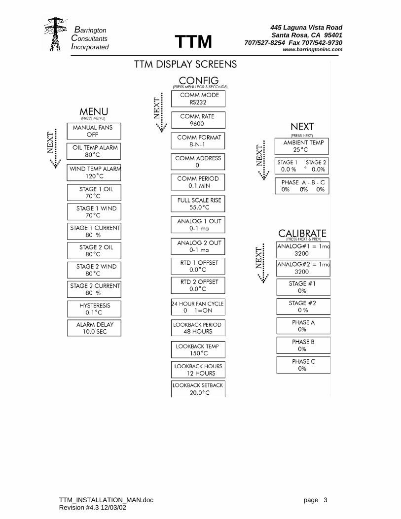
TTM FRONT PANEL CONTROL AND DISPLAYThe new TTM design includes a 2 line by 16 character alpha-numeric display and a five key keypad. This document outlines the basic operation and concepts of the various displays. The TTM has a standard display of temperature data. This standard display will be shown at all times except when a user has entered one of the two menus to setup the control of the TTM. If the user leaves the TTM in one of these menus it will timeout and return to the standard display.
TTM_INSTALLATION_MAN.doc page 2 Revision #4.3 12/03/02
445 Laguna Vista Road Santa Rosa, CA 95401
707/527-8254 Fax 707/542-9730 www.barringtoninc.com
Barrington Consultants Incorporated TTM
TTM_INSTALLATION_MAN.doc page 3 Revision #4.3 12/03/02
445 Laguna Vista Road Santa Rosa, CA 95401
Barrington
707/527-8254 Fax 707/542-9730 www.barringtoninc.com
Consultants Incorporated TTM
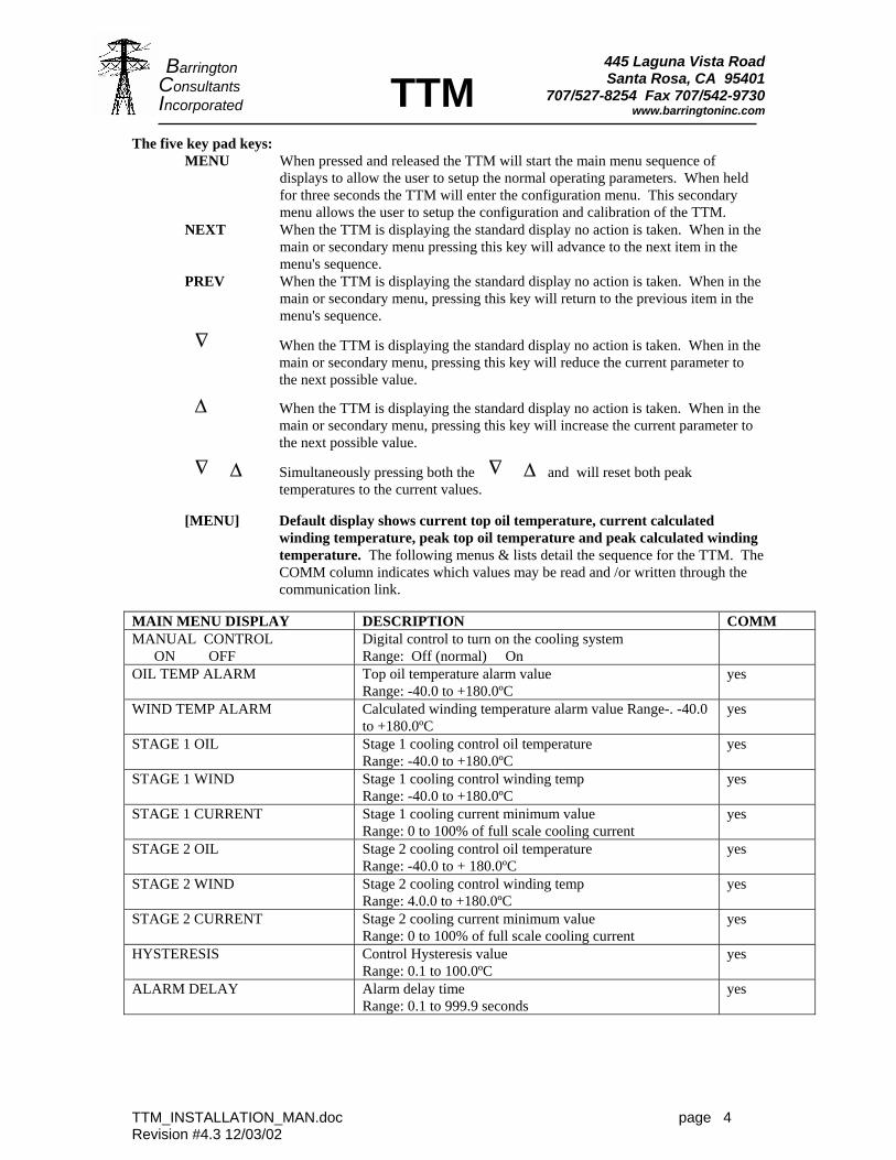
The five key pad keys: MENU When pressed and released the TTM will start the main menu sequence of
displays to allow the user to setup the normal operating parameters. When held for three seconds the TTM will enter the configuration menu. This secondary menu allows the user to setup the configuration and calibration of the TTM.
NEXT When the TTM is displaying the standard display no action is taken. When in the main or secondary menu pressing this key will advance to the next item in the menu's sequence.
PREV When the TTM is displaying the standard display no action is taken. When in the main or secondary menu, pressing this key will return to the previous item in the menu's sequence.
∆
When the TTM is displaying the standard display no action is taken. When in the main or secondary menu, pressing this key will reduce the current parameter to the next possible value.
∆ When the TTM is displaying the standard display no action is taken. When in the main or secondary menu, pressing this key will increase the current parameter to the next possible value.
∆
∆ Simultaneously pressing both the
∆
∆ and will reset both peak temperatures to the current values.
[MENU] Default display shows current top oil temperature, current calculated
winding temperature, peak top oil temperature and peak calculated winding temperature. The following menus & lists detail the sequence for the TTM. The COMM column indicates which values may be read and /or written through the communication link.
MAIN MENU DISPLAY DESCRIPTION COMM MANUAL CONTROL ON OFF
Digital control to turn on the cooling system Range: Off (normal) On
OIL TEMP ALARM Top oil temperature alarm value Range: -40.0 to +180.0ºC
yes
WIND TEMP ALARM Calculated winding temperature alarm value Range-. -40.0 to +180.0ºC
yes
STAGE 1 OIL Stage 1 cooling control oil temperature Range: -40.0 to +180.0ºC
yes
STAGE 1 WIND Stage 1 cooling control winding temp Range: -40.0 to +180.0ºC
yes
STAGE 1 CURRENT Stage 1 cooling current minimum value Range: 0 to 100% of full scale cooling current
yes
STAGE 2 OIL Stage 2 cooling control oil temperature Range: -40.0 to + 180.0ºC
yes
STAGE 2 WIND Stage 2 cooling control winding temp Range: 4.0.0 to +180.0ºC
yes
STAGE 2 CURRENT Stage 2 cooling current minimum value Range: 0 to 100% of full scale cooling current
yes
HYSTERESIS Control Hysteresis value Range: 0.1 to 100.0ºC
yes
ALARM DELAY Alarm delay time Range: 0.1 to 999.9 seconds
yes
TTM_INSTALLATION_MAN.doc page 4 Revision #4.3 12/03/02
445 Laguna Vista Road Santa Rosa, CA 95401
Barrington
707/527-8254 Fax 707/542-9730 www.barringtoninc.com
Consultants Incorporated TTM
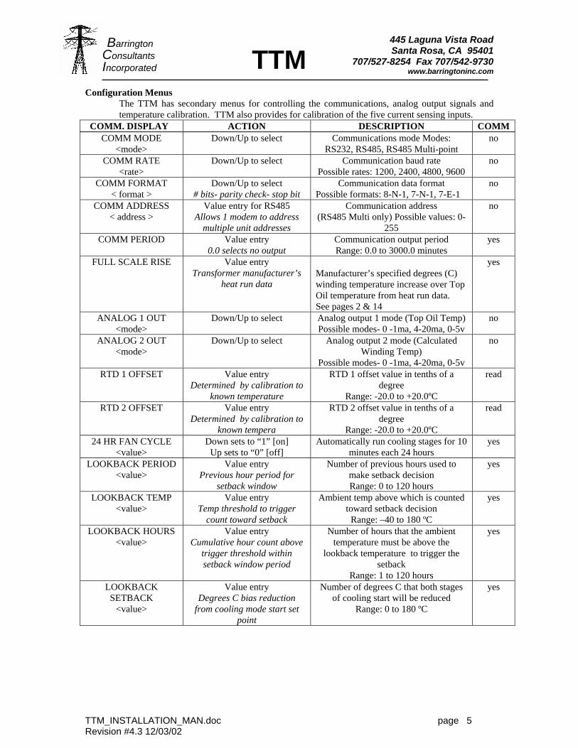
Configuration Menus The TTM has secondary menus for controlling the communications, analog output signals and temperature calibration. TTM also provides for calibration of the five current sensing inputs.
COMM. DISPLAY ACTION DESCRIPTION COMM COMM MODE
<mode> Down/Up to select Communications mode Modes:
RS232, RS485, RS485 Multi-point no
COMM RATE <rate>
Down/Up to select Communication baud rate Possible rates: 1200, 2400, 4800, 9600
no
COMM FORMAT < format >
Down/Up to select # bits- parity check- stop bit
Communication data format Possible formats: 8-N-1, 7-N-1, 7-E-1
no
COMM ADDRESS < address >
Value entry for RS485 Allows 1 modem to address
multiple unit addresses
Communication address (RS485 Multi only) Possible values: 0-
255
no
COMM PERIOD Value entry 0.0 selects no output
Communication output period Range: 0.0 to 3000.0 minutes
yes
FULL SCALE RISE Value entry Transformer manufacturer’s
heat run data Manufacturer’s specified degrees (C) winding temperature increase over Top Oil temperature from heat run data. See pages 2 & 14
yes
ANALOG 1 OUT <mode>
Down/Up to select Analog output 1 mode (Top Oil Temp) Possible modes- 0 -1ma, 4-20ma, 0-5v
no
ANALOG 2 OUT <mode>
Down/Up to select Analog output 2 mode (Calculated Winding Temp)
Possible modes- 0 -1ma, 4-20ma, 0-5v
no
RTD 1 OFFSET Value entry Determined by calibration to
known temperature
RTD 1 offset value in tenths of a degree
Range: -20.0 to +20.0ºC
read
RTD 2 OFFSET Value entry Determined by calibration to
known tempera
RTD 2 offset value in tenths of a degree
Range: -20.0 to +20.0ºC
read
24 HR FAN CYCLE <value>
Down sets to “1” [on] Up sets to “0” [off]
Automatically run cooling stages for 10 minutes each 24 hours
yes
LOOKBACK PERIOD <value>
Value entry Previous hour period for
setback window
Number of previous hours used to make setback decision Range: 0 to 120 hours
yes
LOOKBACK TEMP <value>
Value entry Temp threshold to trigger
count toward setback
Ambient temp above which is counted toward setback decision
Range: –40 to 180 ºC
yes
LOOKBACK HOURS <value>
Value entry Cumulative hour count above
trigger threshold within setback window period
Number of hours that the ambient temperature must be above the
lookback temperature to trigger the setback
Range: 1 to 120 hours
yes
LOOKBACK SETBACK
<value>
Value entry Degrees C bias reduction
from cooling mode start set point
Number of degrees C that both stages of cooling start will be reduced
Range: 0 to 180 ºC
yes
TTM_INSTALLATION_MAN.doc page 5 Revision #4.3 12/03/02
445 Laguna Vista Road Santa Rosa, CA 95401
Barrington
707/527-8254 Fax 707/542-9730 www.barringtoninc.com
TTM_INSTALLATION_MAN.doc page 6
Consultants Incorporated TTM
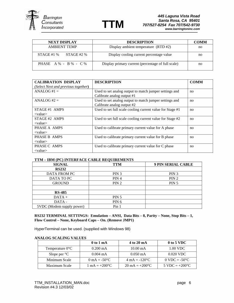
NEXT DISPLAY DESCRIPTION COMM AMBIENT TEMP Display ambient temperature (RTD #2) no
STAGE #1 % STAGE #2 %
Display cooling current percentage value no
PHASE A % - B % - C % Display primary current (percentage of full scale)
no
CALIBRATION DISPLAY (Select Next and previous together)
DESCRIPTION COMM
ANALOG #1 = Used to set analog output to match jumper settings and Calibrate analog output #1
no
ANALOG #2 = Used to set analog output to match jumper settings and Calibrate analog output #2
no
STAGE #1 AMPS <value>
Used to set full scale cooling current value for Stage #1 no
STAGE #2 AMPS <value>
Used to set full scale cooling current value for Stage #2 no
PHASE A AMPS <value>
Used to calibrate primary current value for A phase no
PHASE B AMPS <value>
Used to calibrate primary current value for B phase no
PHASE C AMPS <value>
Used to calibrate primary current value for C phase no
TTM – IBM (PC) INTERFACE CABLE REQUIREMENTS
SIGNAL TTM 9 PIN SERIAL CABLE RS232
DATA FROM PC PIN 3 PIN 3 DATA TO PC PIN 4 PIN 2
GROUND PIN 2 PIN 5
RS-485 DATA + PIN 5 DATA - PIN 6
5VDC (Modem supply power) Pin 1 RS232 TERMINAL SETTINGS: Emulation – ANSI, Data Bits – 8, Parity – None, Stop Bits – 1, Flow Control – None, Keyboard Caps – On. (Remove JMP1) HyperTerminal can be used. (supplied with Windows 98) ANALOG SCALING VALUES
0 to 1 mA 4 to 20 mA 0 to 5 VDC Temperature 0°C 0.200 mA 10.00 mA 1.00 VDC
Slope per °C 0.004 mA 0.050 mA 0.020 VDC Minimum Scale 0 mA = -50°C 4 mA = -120°C 0 VDC = -50°C Maximum Scale 1 mA = +200°C 20 mA = +200°C 5 VDC = +200°C
Revision #4.3 12/03/02
445 Laguna Vista Road Santa Rosa, CA 95401
707/527-8254 Fax 707/542-9730 www.barringtoninc.com
TTM_INSTALLATION_MAN.doc page 7
Barrington Consultants Incorporated TTM
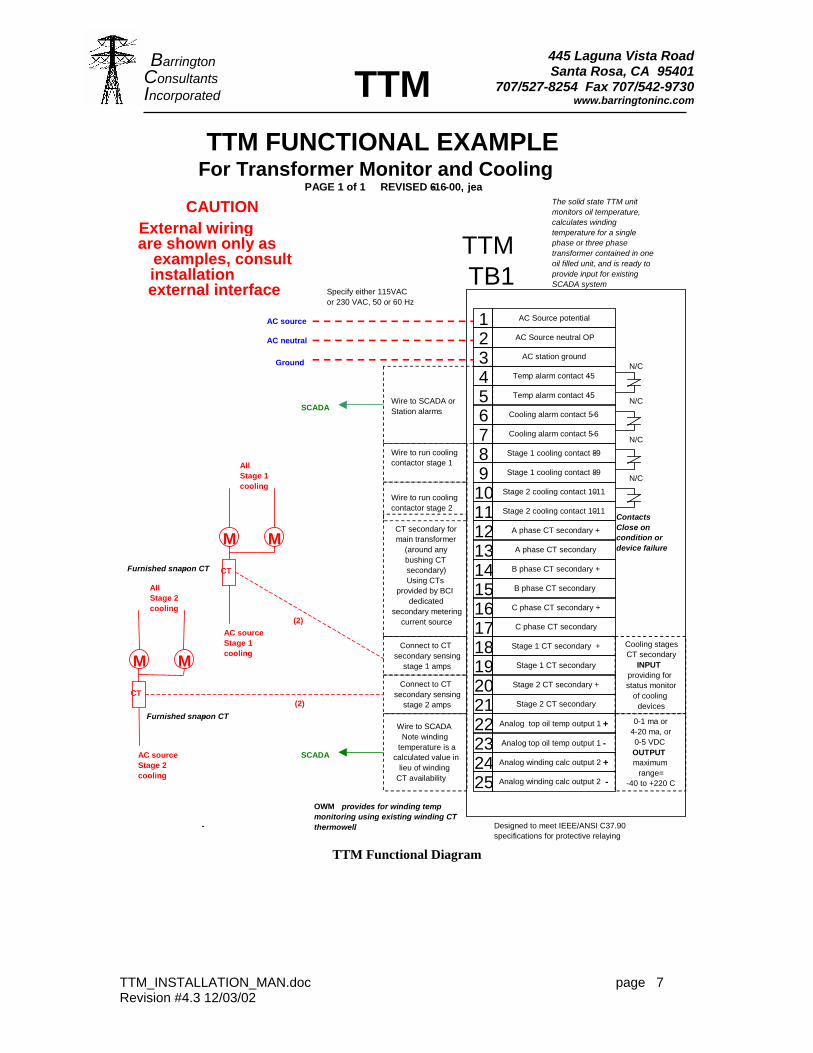
TTM
TB1
23
1
87
456
Wire to SCADA orStation alarms
-
Specify either 115VAC or 230 VAC, 50 or 60 Hz
CAUTION External wiring are shown only as
examples, consult installation external interface
M
Designed to meet IEEE/ANSI C37.90 specifications for protective relaying
TTM FUNCTIONAL EXAMPLE For Transformer Monitor and Cooling C PAGE 1 of 1 REVISED 6-16-00, jea
The solid state TTM unit monitors oil temperature, calculates winding temperature for a single phase or three phase transformer contained in one oil filled unit, and is ready to provide input for existing SCADA system
910111213141516171819202122
252423
AC Source potential AC Source neutral OP
Temp alarm contact 4 - 5 Temp alarm contact 4 - 5
AC station ground
Cooling alarm contact 5 - 6 Cooling alarm contact 5 - 6 Stage 1 cooling contact 8 - 9 Stage 1 cooling contact 8 - 9
Stage 2 cooling contact 10 - 11 Stage 2 cooling contact 10 - 11
A phase CT secondary +
Stage 1 CT secondary Stage 1 CT secondary + C phase CT secondary
C phase CT secondary + B phase CT secondary
B phase CT secondary + A phase CT secondary
Analog winding calc output 2 - Analog winding calc output 2 + Analog top oil temp output 1 - Analog top oil temp output 1 +
Stage 2 CT secondary Stage 2 CT secondary +
N/C
N/C
N/C
N/C Wire to run cooling contactor stage 1
Wire to run cooling contactor stage 2
Cooling stages CT secondary
INPUTproviding for status monitor
of cooling devices
0 - 1 ma or4 - 20 ma, or 0 - 5 VDC OUTPUT maximum
range=- 40 to +220 C
Wire to SCADANote winding
temperature is a calculated value in
lieu of winding CT availability
Connect to CT secondary sensing
stage 1 amps
Connect to CT secondary sensing
stage 2 amps
AC source Stage 2 cooling
CT
M
All Stage 2 cooling
M
AC source Stage 1 cooling
CT
M
All Stage 1 cooling
SCADA
SCADA
(2)
(2)
Ground AC neutral AC source
CT secondary for main transformer
(around any bushing CT secondary)Using CTs
provided by BCI dedicated
secondary metering current source
OWM provides for winding temp monitoring using existing winding CT thermowell.
Furnished snap - on CT
Furnished snap - on CT
Contacts Close on condition ordevice failure
TTM Functional Diagram
Revision #4.3 12/03/02
445 Laguna Vista Road Santa Rosa, CA 95401
707/527-8254 Fax 707/542-9730 www.barringtoninc.com
TTM_INSTALLATION_MAN.doc page 8
Barrington Consultants Incorporated TTM
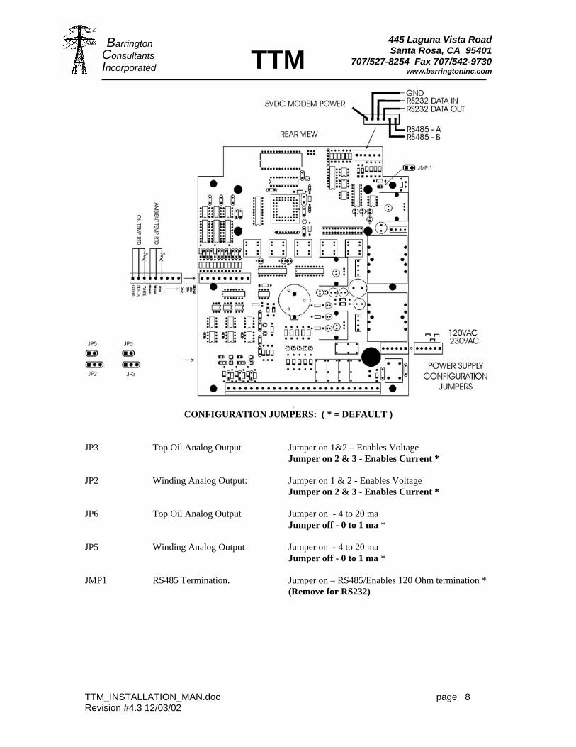
CONFIGURATION JUMPERS: ( * = DEFAULT ) JP3 Top Oil Analog Output Jumper on 1&2 – Enables Voltage Jumper on 2 & 3 - Enables Current * JP2 Winding Analog Output: Jumper on 1 & 2 - Enables Voltage Jumper on 2 & 3 - Enables Current * JP6 Top Oil Analog Output Jumper on - 4 to 20 ma Jumper off - 0 to 1 ma * JP5 Winding Analog Output Jumper on - 4 to 20 ma Jumper off - 0 to 1 ma * JMP1 RS485 Termination. Jumper on – RS485/Enables 120 Ohm termination * (Remove for RS232)
Revision #4.3 12/03/02
445 Laguna Vista Road Santa Rosa, CA 95401
Barrington
707/527-8254 Fax 707/542-9730 www.barringtoninc.com
TTM_INSTALLATION_MAN.doc page 9
Consultants Incorporated TTM
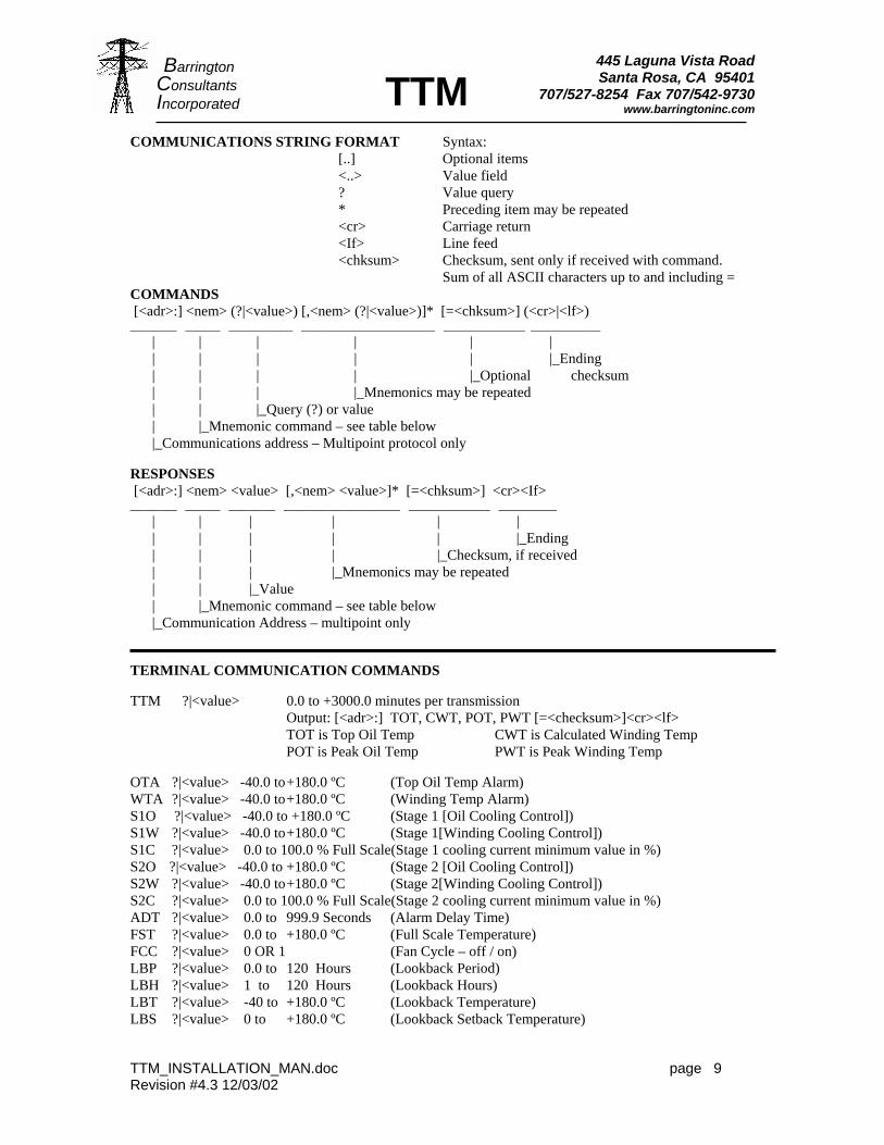
COMMUNICATIONS STRING FORMAT Syntax: [..] Optional items <..> Value field ? Value query * Preceding item may be repeated <cr> Carriage return <If> Line feed
<chksum> Checksum, sent only if received with command. Sum of all ASCII characters up to and including = COMMANDS [<adr>:] <nem> (?|<value>) [,<nem> (?|<value>)]* [=<chksum>] (<cr>|<lf>) ________ ______ ___________ _______________________ ______________ ____________ | | | | | | | | | | | |_Ending | | | | |_Optional checksum | | | |_Mnemonics may be repeated | | |_Query (?) or value | |_Mnemonic command – see table below |_Communications address – Multipoint protocol only RESPONSES [<adr>:] <nem> <value> [,<nem> <value>]* [=<chksum>] <cr><If> ________ ______ ________ ____________________ ______________ __________ | | | | | | | | | | | |_Ending | | | | |_Checksum, if received | | | |_Mnemonics may be repeated | | |_Value | |_Mnemonic command – see table below |_Communication Address – multipoint only TERMINAL COMMUNICATION COMMANDS TTM ?|<value> 0.0 to +3000.0 minutes per transmission Output: [<adr>:] TOT, CWT, POT, PWT [=<checksum>]<cr><lf> TOT is Top Oil Temp CWT is Calculated Winding Temp POT is Peak Oil Temp PWT is Peak Winding Temp OTA ?|<value> -40.0 to +180.0 ºC (Top Oil Temp Alarm) WTA ?|<value> -40.0 to +180.0 ºC (Winding Temp Alarm) S1O ?|<value> -40.0 to +180.0 ºC (Stage 1 [Oil Cooling Control]) S1W ?|<value> -40.0 to +180.0 ºC (Stage 1[Winding Cooling Control]) S1C ?|<value> 0.0 to 100.0 % Full Scale(Stage 1 cooling current minimum value in %) S2O ?|<value> -40.0 to +180.0 ºC (Stage 2 [Oil Cooling Control]) S2W ?|<value> -40.0 to +180.0 ºC (Stage 2[Winding Cooling Control]) S2C ?|<value> 0.0 to 100.0 % Full Scale(Stage 2 cooling current minimum value in %) ADT ?|<value> 0.0 to 999.9 Seconds (Alarm Delay Time) FST ?|<value> 0.0 to +180.0 ºC (Full Scale Temperature) FCC ?|<value> 0 OR 1 (Fan Cycle – off / on) LBP ?|<value> 0.0 to 120 Hours (Lookback Period) LBH ?|<value> 1 to 120 Hours (Lookback Hours) LBT ?|<value> -40 to +180.0 ºC (Lookback Temperature) LBS ?|<value> 0 to +180.0 ºC (Lookback Setback Temperature)
Revision #4.3 12/03/02
445 Laguna Vista Road Santa Rosa, CA 95401
Barrington
707/527-8254 Fax 707/542-9730 www.barringtoninc.com
TTM_INSTALLATION_MAN.doc page 10
Consultants Incorporated TTM
FRONT PANEL LED INDICATORS AND ALARMS
EACH LED INDICATOR WILL LIGHT CONTINUOULSY WHILE AN ALARM CONDITION IS PRESENT. EACH LED WILL BLINK IF THE ALARM CONDITION IS NO LONGER VALID. BLINKING WILL CONTINUE UNTIL THE TTM HAS BEEN RESET BY PUSHBUTTONS. This feature is useful to identify the cause of short term alarm conditions.
EXPLANATION OF HYSTERESIS
The HYSTERESIS setting is a deadband adjustment for toggling an event or alarm. It is there to increase stability and prevent fast on-off operations of alarms and events.
Example 1: (HYSTERESIS = 2.0 deg C and Alarm is set for 60 Deg C.) Alarm is activated at 60 Deg. C (After ALARM TIME DELAY) Alarm will not reset until temperature is reduced to 58 Deg. C. Example 2: (HYSTERESIS = 2.0 deg C and cooling stage #1 is set to start at 50 Deg C.) Cooling starts at 50 Deg. Cooling stage #1 runs until temperature is reduced to 48 Deg. C. (This will prevent repeated application of starting current to the cooling motors) Lookback setback example: Given lookback period setting= 96 hours; Lookback temperature setting=+33 C (“+” sign not entered on TTM); Lookback hours setting= 8 hours; and Lookback setback= 10 C. In a rolling window of 96 hours from any present hour, when there have been 8 cumulative hours during which the ambient temperature exceeded 33 C (91.4 F), the cooling devices start point will be biased to initiate 10 degrees C less than the TTM display cooling mode entered set point.
Revision #4.3 12/03/02
445 Laguna Vista Road Santa Rosa, CA 95401
Barrington
707/527-8254 Fax 707/542-9730 www.barringtoninc.com
TTM_INSTALLATION_MAN.doc page 11
Consultants Incorporated TTM
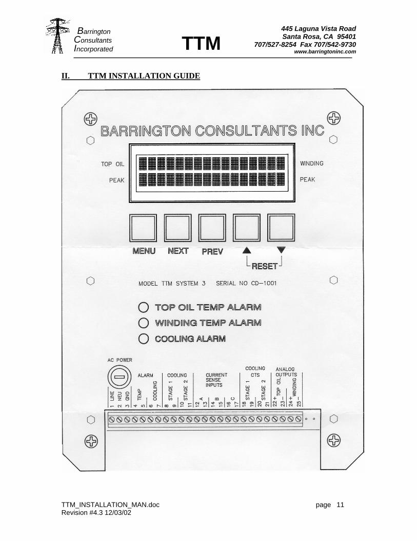
II. TTM INSTALLATION GUIDE
Revision #4.3 12/03/02
445 Laguna Vista Road Santa Rosa, CA 95401
707/527-8254 Fax 707/542-9730 www.barringtoninc.com
TTM_INSTALLATION_MAN.doc page 12
Barrington Consultants Incorporated TTM
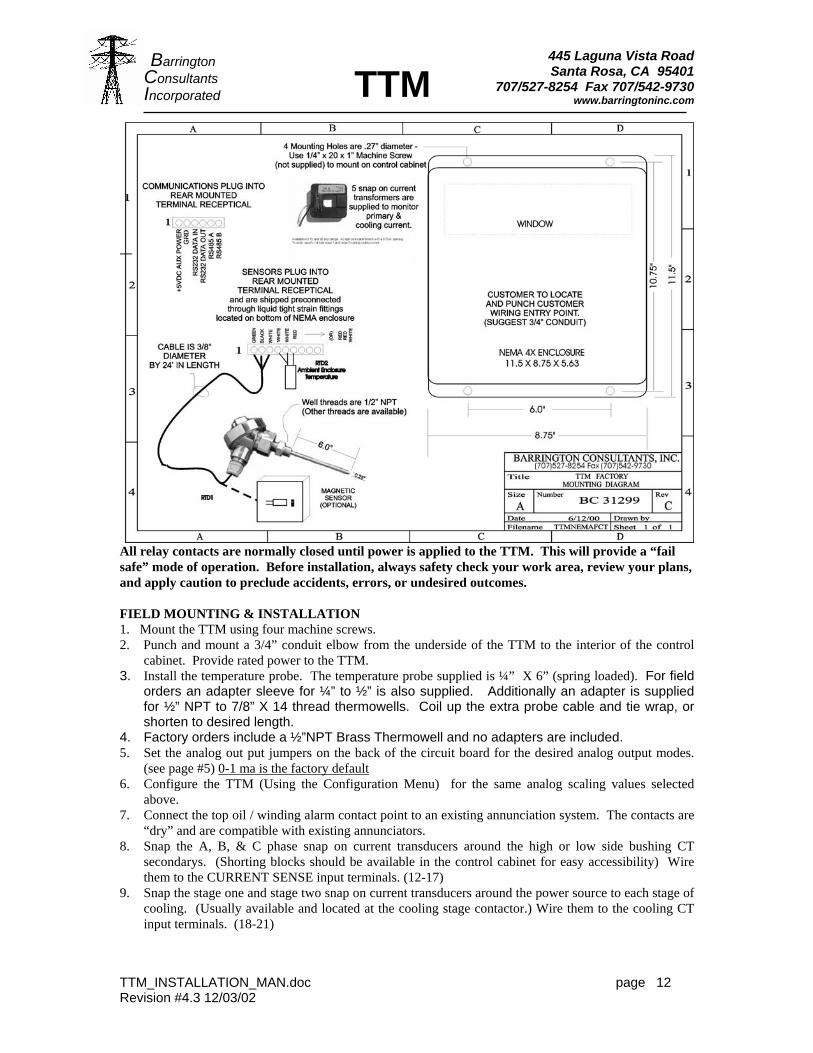
All relay contacts are normally closed until power is applied to the TTM. This will provide a “fail safe” mode of operation. Before installation, always safety check your work area, review your plans, and apply caution to preclude accidents, errors, or undesired outcomes.
FIELD MOUNTING & INSTALLATION 1. Mount the TTM using four machine screws. 2. Punch and mount a 3/4” conduit elbow from the underside of the TTM to the interior of the control
cabinet. Provide rated power to the TTM. 3. Install the temperature probe. The temperature probe supplied is ¼” X 6” (spring loaded). For field
orders an adapter sleeve for ¼” to ½” is also supplied. Additionally an adapter is supplied for ½” NPT to 7/8” X 14 thread thermowells. Coil up the extra probe cable and tie wrap, or shorten to desired length.
4. Factory orders include a ½”NPT Brass Thermowell and no adapters are included. 5. Set the analog out put jumpers on the back of the circuit board for the desired analog output modes.
(see page #5) 0-1 ma is the factory default 6. Configure the TTM (Using the Configuration Menu) for the same analog scaling values selected
above. 7. Connect the top oil / winding alarm contact point to an existing annunciation system. The contacts are
“dry” and are compatible with existing annunciators. 8. Snap the A, B, & C phase snap on current transducers around the high or low side bushing CT
secondarys. (Shorting blocks should be available in the control cabinet for easy accessibility) Wire them to the CURRENT SENSE input terminals. (12-17)
9. Snap the stage one and stage two snap on current transducers around the power source to each stage of cooling. (Usually available and located at the cooling stage contactor.) Wire them to the cooling CT input terminals. (18-21)
Revision #4.3 12/03/02
445 Laguna Vista Road Santa Rosa, CA 95401
Barrington
707/527-8254 Fax 707/542-9730 www.barringtoninc.com
TTM_INSTALLATION_MAN.doc page 13
Consultants Incorporated TTM
CALIBRATING MAIN TANK AND AMBIENT TEMP ANALOG OUTPUT VALUES Pressing “NEXT” AND “PREVIOUS” at the same time enters the calibration mode. 1. Determine which analog output is desired and configure the jumpers on the rear of the circuit board.
Note: Remove the 120 ohm termination jumper (JMP1) for RS232 applications. The following is a description of the 0 – 1 mA calibration procedure.
2. Enter the configuration mode by pressing menu and holding for 3 seconds. 3. Configure the analog outputs to match the output jumpers selected in step 1. 4. Press “MENU” (or wait for 30 seconds) to return to the default four temperature display. 5. Enter calibration procedure by pressing “NEXT” AND “PREV” AT THE SAME TIME. 6. Display will read ANALOG #1. 7. With a very accurate DC ammeter, read current across analog output #1. 8. Current should read 1.000 DC ma. 9. Using the up and down arrows, adjust the output voltage to read 1.000 DC mA. 10. Pressing “NEXT” will display ANALOG OUTPUT #2. 11. Repeat steps 7 and 8 for analog #2. 12. Press the “MENU” key (or wait for 30 seconds) to return to normal operation. CALIBRATING STAGE 1 AND STAGE 2 100% CURRENT VALUES Pressing “NEXT” AND “PREVIOUS” at the same time enters the calibration mode. 1. After entering the calibration mode, press next until the Stage#1 display appears. 2. While stage #1 cooling is running, adjust the percentage to 100%. Use up or down arrow to nudge the
percentage values. Note: Pressing both the up and down arrows simultaneously will automatically set the 100% value. The current transformer normally supplied is rated for 15 amps AC cooling current. (Other ranges are available)
3. Press next until the Stage#2 display appears. 4. While stage #2 cooling is running, adjust the percentage to 100%. Use up or down arrow to nudge the percentage values. Note: Pressing both the up and down arrows simultaneously will automatically set the 100% value. The current transformer normally supplied is rated for 15 amps AC cooling current. (Other ranges are available) CALIBRATING A B & C PHASE 100% CURRENT VALUES THE TTM IS SET AT THE FACTORY FOR 5 AMPS SECONDARY EQUALS 100% PRIMARY CURRENT. Pressing “NEXT” AND “PREVIOUS” at the same time enters the calibration mode. (METHOD #1) 1. After entering the calibration mode, press next until the PHASE A display appears. 2. While applying 5 amps (or full scale secondary CT rated current) through the A PHASE snap on
current transformer, adjust the percentage to 100%. Use up or down arrow to nudge the percentage values. Note: Pressing both the up and down arrows simultaneously will automatically set (“LEARN”) the 100% value.
3. Press next until the PHASE B display appears. 4. While applying 5 amps (or full scale secondary CT current) through the B PHASE snap on current
transformer, adjust the percentage to 100%. Use up or down arrow to nudge the percentage values. Note: Pressing both the up and down arrows simultaneously will automatically set the 100% value.
5. Press next until the PHASE C display appears. 1. While applying 5 amps (or full scale secondary CT current) through the C PHASE snap on current
transformer, adjust the percentage to 100%. Use up or down arrow to nudge the percentage values. Note: Pressing both the up and down arrows simultaneously will automatically set the 100% value.
(METHOD #2) This calibration method is useful for installation on in service transformers 1. Determine the current percentage of full load current.
Revision #4.3 12/03/02
445 Laguna Vista Road Santa Rosa, CA 95401
Barrington
707/527-8254 Fax 707/542-9730 www.barringtoninc.com
TTM_INSTALLATION_MAN.doc page 14
Consultants Incorporated TTM
2. After entering the calibration mode, (NEXT AND PREVIOUS) press next until the PHASE A display appears.
3. Adjust the calibration percentage (USING THE UP AND DOWN ARROWS) to match the actual percentage.
4. Press NEXT to display PHASE B. 5. Repeat step 3. 6. Press NEXT to display PHASE C. 7. Repeat step 3. The display “Full Scale Rise” refers to the winding temperature increase above Top Oil temperature furnished by the manufacturer. The TTM calculates the winding temperature as a direct degree (C) increase over top oil temperature based upon this data. Using the configuration menu enter the full scale winding temperature increase over the oil temperature provided by the transformer manufacturer’s heat run data. This data refers to the C temperature difference between the transformer main tank oil temperature and the winding temperature at full rated load. The referenced value is not nameplate ambient temperature rise. The winding temperature is calculated based upon the highest of the three current values. If the manufacturer’s value has been de-rated or modified by your authorized in-house actions, use the value specified by your authorized alternative sources. For installation on single phase transformers connect only one of the snap on CTs. Barrington consultants would appreciate any feedback about the TTM. We want to provide top quality products to satisfied customers. We will be happy to answer any questions you might have about installation or operation of our products. It is the user’s responsibility to determine proper set points, adequately engineer, test, install, and ensure desired operating status. Barrington Consultants Inc. assumes no responsibility for installation or user operation of the TTM.
Revision #4.3 12/03/02
445 Laguna Vista Road Santa Rosa, CA 95401
Barrington
707/527-8254 Fax 707/542-9730 www.barringtoninc.com
TTM_INSTALLATION_MAN.doc page 15
Consultants Incorporated TTM
TTM SPECIFICATIONS RTD -100°C to 600°C (DIN 43760 Class B) .00385 ohms/ohm/ °C STABILITY Maximum change in ice point resistance of less than 0.2°C/Year REPEATABILITY 0.05% of actual span INPUT Dual Pt 100 RTD (One Top Oil Temp & One Ambient Temp) TOP OIL INPUT PROBE TYPE (1ea) 6” X ¼” probe W ½” NPT Thread (7/8” X 14 thread adapter supplied) or (1ea)
75LB Pull Surface Magnetic INPUT PROBE CABLE 24’ type UV/SJT INPUT SPAN -40�C Min 200°C Max ANALOG OUTPUT 0 - 5V, 0-1mA or 4-20mA (Independently selectable) CALIBRATION Automatic -40°C to 200°C LINEARITY Better than 0.2% of span LEAD WIRE COMP. Automatic – 3 wire TEMPERATURE STABILITY Better than .03% /°C of span Surge Withstand Designed to meet ANSII/IEEE C37.90 C.M.R.R. 120db DC to 60 Hz POWER SUPPLY RANGE 115/230VAC - 50/60Hz OPERATING TEMP. -20°C (-40 optional heater) to +75°C ENCLOSURE NEMA 4 10” X 8” X 6”
DIGITAL RESOLUTION: >12 bits.
OVERALL ACCURACY Less than 0.3°C input temperature / display
ALARM: Dry contact spst relay output rated @ 5A 250 VAC.
ALARM RESPONSE TIME: Programmable - .1 sec to 999.9 sec.
ALARM HYSTERESIS 0.1 TO 100 DEG C (DEAD BAND)
DISPLAY: 16 × 2 Character .39” LCD indicator for programming and display of input and output parameters and status.
SUPPLY: AC: 115 or 230 VAC 50/60 Hz ± 10%, OPERATINGCONDITIONS: -40°C to +75°C. 0-95% RH, non condensing.
STORAGE TEMP.: -55°C to 105°C.
HUMIDITY: 0-95% RH, non condensing.
TURN-ON TIME: Within 10 seconds to rated response.
RESPONSE TIME: 5 seconds to 99% of reading. (1 update/second).
DAMPING FACTOR: 3.0 Seconds.
TTM LONG TERMSTABILITY: Less than ±0.1% of span for six months.
(D/A) LINEARITY: ±O.O5% of span.
LINEARIZATION: better than ±0.03°C for Pt-100 RTD,
CALIBRATION: adjustable on-site, factory preadjusted
Revision #4.3 12/03/02
445 Laguna Vista Road Santa Rosa, CA 95401
Barrington
707/527-8254 Fax 707/542-9730 www.barringtoninc.com
TTM_INSTALLATION_MAN.doc page 16
Consultants Incorporated TTM
ORDERING INFORMATION
ALL PURCHASE ORDERS TO BE MADE TO:
BARRINGTON CONSULTANTS, INC. 445 Laguna Vista Road Santa Rosa, CA. 95401
707-527-8254 FAX 707-542-9730
TTM, Transformer Temperature Monitor, Complete with Standard 6” ½”NPT thread replacement RTD well probe, 24ft
SJT UV treated connector cables, 5 Snap-On current transformers, SCADA ready outputs for Top Oil, Calculated Winding Temperatures, Two adjustable dry contacts for temperature and cooling alarms, Ambient compensation, 2 stage cooling control, Four display readout with Top oil, Calculated Winding, Peak Top oil, and Peak Winding temperatures, RS232/485/485 multipoint communications. NEMA type 4x windowed enclosure. Delivery - Stock to 6 weeks ARO
The TTM may be special ordered with the following options: 1. Universal power input capability 100 to 270 Volts AC/DC 2. Special sensor probe lengths and threads. 3. Top Oil and/or Winding Temperature TRIP capability 4. Various Cooling CT ratioes. 15, 30, 60, 100 Amp 5. Substitute Magnetic surface mount RTD temperature probe instead of thermowell
RTD probe. 6. ¼” x 6” ½”NPT Brass Thermowell 7. 7/8 x 14 thread adapter for 7/8 x 14 thermowell ********************************************************************
SIMILAR PRODUCT AVAILABLE
OWM, Oil & Winding Temperature Monitor, Complete with Dual Standard 6” X ½ NPT thread replacement RTD well probes, 24ft
SJT UV treated connector cables, 2 Snap-On current transformers, SCADA ready outputs for Top Oil & Winding Temperatures, Two adjustable dry contacts for temperature and cooling alarms, Ambient compensation, 2 stage cooling control, Four display readout with Top oil, Winding, Peak Top oil, and Peak Winding temperatures, RS232/485/485 multipoint communications. NEMA type 4 windowed enclosure. Delivery 6-8 weeks ARO
The OWM may be special ordered with any of the previous options:
Revision #4.3 12/03/02
445 Laguna Vista Road Santa Rosa, CA 95401
707/527-8254 Fax 707/542-9730 www.barringtoninc.com
TTM_INSTALLATION_MAN.doc page 17
Barrington Consultants Incorporated TTM
Revision #4.3 12/03/02