balancesystemsd - biodex operation/servicemanual 950-300 950-302 950-304 biodex biodex medical...
TRANSCRIPT
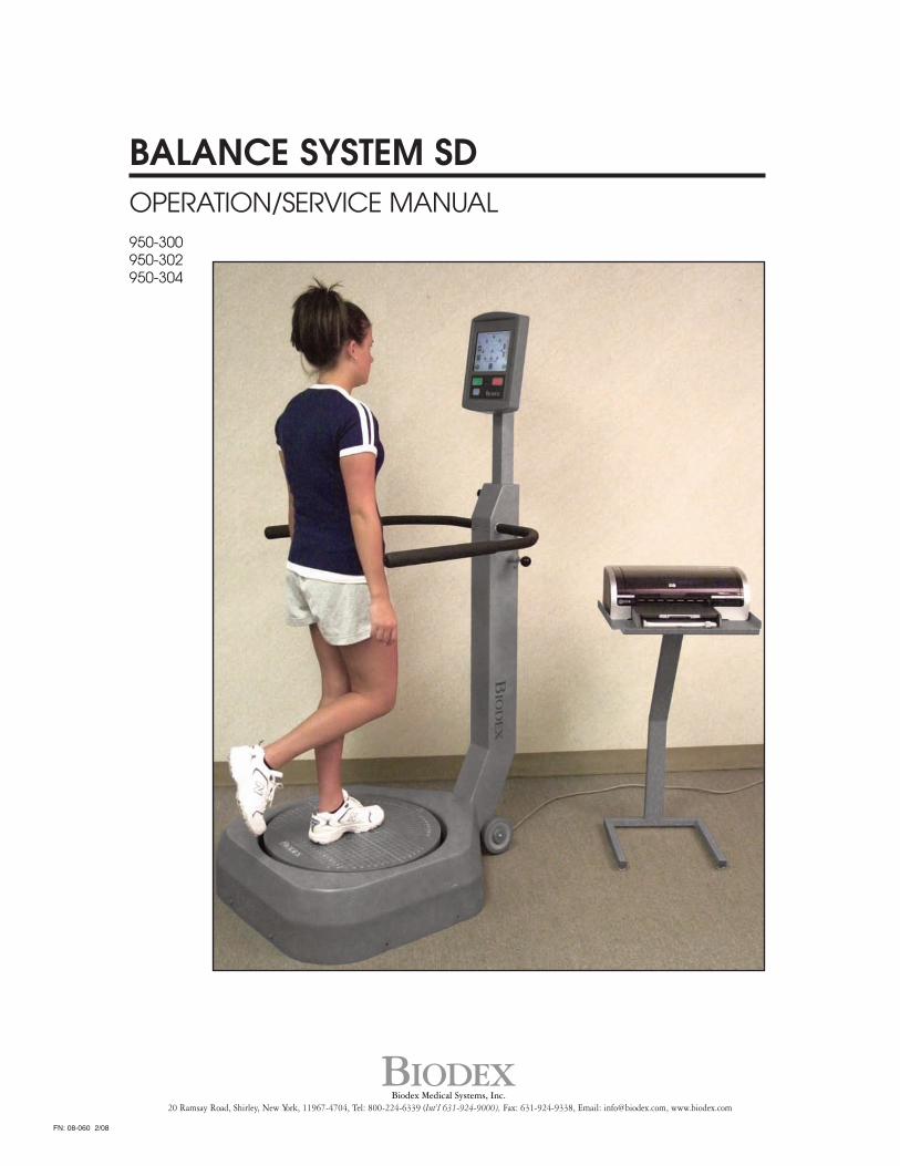
BALANCE SYSTEM SDOPERATION/SERVICE MANUAL950-300950-302950-304
BIODEXBiodex Medical Systems, Inc.
20 Ramsay Road, Shirley, New York, 11967-4704, Tel: 800-224-6339 (Int’l 631-924-9000), Fax: 631-924-9338, Email: [email protected], www.biodex.com
FN: 08-060 2/08

This manual covers installation and operation proceduresfor the following products:#950-300 System, Balance SD, 115 VAC#950-302 System, Balance SD, 230VAC#950-304 System, Balance SD, 100V Japanese
BALANCE SYSTEM
NOTE: The following symbol on your Biodex Balance System corresponds to this operation manual:
Symbol Meaning: attention, consult accompanying documentsSymbol Signification: Attention, se référer à la noticeCAUTION: Federal law restricts this device to sale or on the order of a medical practitioner. Whenprescribed for therapeutic purpose, a physician should clearly define the parameters of use (i.e.,total work, maximum heart rate, etc.) to reduce the risk of patient injury.
— II —
1. Introduction ......................................................................................................................................1-12. System Specifications ......................................................................................................................2-13. Assembly and Installation ..............................................................................................................3-1
• Printer Installation• Parts and Adjustments
4. Clinical Considerations....................................................................................................................4-1• General Clinical Considerations• Additional Considerations For Fall Prevention Programs
5. Applications ......................................................................................................................................5-1• Orthopedic and Sports Medicine• Fall Prevention• Reference Notes
6. Getting Started ..................................................................................................................................6-1• Accessing the Main Menu• Display Panel Keys Described• Screen Keys
7. The Training Routine........................................................................................................................7-1• Postural Stability Training• Limits of Stability (LOS) Training• Weight Shift Training• Maze Control Training• Random Control Training• Percent Weight-Bearing Training
8. Testing ................................................................................................................................................8-1• The Postural Stability Test• The Limits of Stability Test• Athlete Single Leg Stability Testing• Performing a Fall Risk Test
9. Reports................................................................................................................................................9-1• Report Parameters Defined• Progress Reports• Sample Balance Reports
10. Data ..................................................................................................................................................10-1• Assessing Limits of Stability With The Biodex Balance System• Understanding Patient Performance• Balance System Statistics Defined
11. System Utilities................................................................................................................................11-1• Configuration ..............................................................................................................................11-2• Patient Management ..................................................................................................................11-2
12. Reimbursement ..............................................................................................................................12-113. General Maintenance ....................................................................................................................13-114. Bibliography ....................................................................................................................................14-1Appendix A: Calculation of Limits of Stability Direction Control..................................................A-1Appendix B: Normative Data Referenced in Predictive Values Report..........................................B-1Replacement: R-1
TABLE OF CONTENTS
— III — TABLE OF CONTENTS

Figure 1.1: The Biodex Balance System SD primary components and adjustment mechanisms.
1. INTRODUCTION
— 1-1 — INTRODUCTION
Display Module
Auxillary Serial Port
USB Printer port
Display Height Locking Knob
Support Handle
Support Handle Release Pin
Printer
Printer Stand
Power Cord
Wheels
Foot Platform
Featuring four test protocols, six training modes and intuitive “touch-screen” operation, theBalance System SD allows testing and training in both static and dynamic formats. Extremelyversatile, it is the only system that provides fast, accurate Fall Risk Assessment and Conditioningfor older adults plus closed-chain, weight-bearing assessment and training for lower extremitypatients.
Using this unique device, clinicians can assess neuromuscular control by quantifying the ability tomaintain dynamic bilateral and unilateral postural stability on a static or unstable surface. Use anyof four test protocols including fall risk, athletic single leg stability, limits of stability and posturalstability. The Balance System SD also serves as a valuable training device to enhance kinestheticabilities that may provide some degree of compensation for impaired proprioceptive reflex mecha-nisms following injury.
An easy to follow touch-screen format makes the system simple to learn and operate, leadingthe user step-by-step through testing protocols and training modes. All test results and trainingsessions are documented on easy to read 8.5" x 11" reports which can be placed into thepatient's file. Comparisons to normative data can be made for population-specific tests usingthe Fall Screening and Athlete Single Leg Stability protocols.
1. INTRODUCTION
INTRODUCTION — 1-2 —
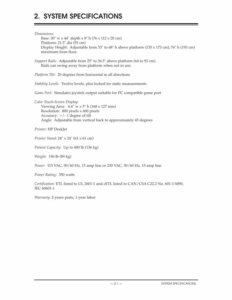
Dimensions:Base: 30" w x 44" depth x 8" h (76 x 112 x 20 cm)Platform: 21.5" dia (55 cm)Display Height: Adjustable from 53" to 68" h above platform (135 x 173 cm); 76" h (193 cm)maximum from floor.
Support Rails: Adjustable from 25" to 36.5" above platform (64 to 93 cm).Rails can swing away from platform when not in use.
Platform Tilt: 20 degrees from horizontal in all directions
Stability Levels: Twelve levels, plus locked for static measurements
Game Port: Simulates joystick output suitable for PC compatible game port
Color Touch-Screen Display:Viewing Area: 6.6" w x 5" h (168 x 127 mm)Resolution: 800 pixels x 600 pixelsAccuracy: +/- 1 degree of tiltAngle: Adjustable from vertical back to approximately 45 degrees
Printer: HP DeskJet
Printer Stand: 24" x 24" (61 x 61 cm)
Patient Capacity: Up to 400 lb (136 kg)
Weight: 196 lb (89 kg)
Power: 115 VAC, 50/60 Hz, 15 amp line or 230 VAC, 50/60 Hz, 15 amp line
Power Rating: 350 watts
Certification: ETL listed to UL 2601-1 and cETL listed to CAN/CSA C22.2 No. 601-1-M90,IEC 60601-1
Warranty: 2-years parts, 1-year labor
2. SYSTEM SPECIFICATIONS
— 2-1 — SYSTEM SPECIFICATIONS

The Biodex Balance System SD is shipped in a single carton. Except for the printer, which the usermust install as explained below, the entire system is factory assembled and ready to operate.
If desired, the system can be configured for PC computer compatibility, allowing the foot plateto be used like a joystick for interactive video game use. Joystick options are discussed in theSystem Utilities chapter.
PRINTER INSTALLATION(See Figures 3.1 and 3.2)
NOTE: It may be necessary to have the help of another person to steady the printer during the followingprocedure.
1. Refer to the supplied printer manual to unpack the printer and ensure that it has not beendamaged by shipping.
2. Position the printer on the printer stand as shown.
3. Locate the black printer power cable. Plug the small end into the power receptacle on the backof the printer. Do not connect any other equipment to this receptacle.
4. Plug the AC plug end of the power cable into power cable port on the back, lower base of theBalance System.
5. Locate the white USB cable. Connect one end of the cable to the USB port on back of theBalance System display. Connect the other end of the cable to the USB port at the back of theprinter directly above the power cable port.
6. Ensure both cables are positioned so that they will not interfere with the patient or get caughtin the Balance System platform or handles.
7. Insert several sheets of paper into the printer paper holder. Insert the paper holder into thetop of the printer so that the open end interlocks with the printer and the paper faces outtoward you.
8. With power ON to the Balance System, press the <Power ON> switch on the printer. Ensurethe printer's green Ready LED comes on to indicate the printer is receiving power. Refer to thesupplied printer manual for additional printer information.
3. ASSEMBLY & INSTALLATION
— 3-1 — ASSEMBLY & INSTALLATION

Figure 3.1. The printer power cable should be plugged into the AC receptacle on the rear base of the dis-play support post. The printer USB cable should be plugged into the USB port on back of the display.
Figure 3.2. Connect the power cable and USB cable to the rear of the printer.
CONTENTS
ASSEMBLY & INSTALLATION — 3-2 —
USB Printer Port
AuxiliarySerial Port
PARTS AND ADJUSTMENTS(See Figure 3.3.)
Mechanical adjustments to the Biodex Balance System are straightforward and uncomplicated.In fact, there are only three adjustments that need be addressed to accommodate any patient:Support Handle Position, Display Height and Display Tilt. All other test and exercise functionsare software controlled.
To Adjust the Support Handle:
1. To position the Support Handle for patient use, hold the Support Handle while pulling out onthe Support Handle Release Pin. Rotate the handle to the desired position. Release the pin tolock the Support Handle in place.
2. To release the Support Handle so that it cannot be used by the patient, hold the handle whilepulling out on the Support Handle Release Pin. Fully lower the handle, then release the pin.
Ajustement de l’appui
1. Pour régler l’angle de l’appui, le tenir tout en tirant sur le verrou. Trouver la position voulue,relâcher le verrou pour garder la position ainsi trouvée.
2. Pour écarter l’appui, le baisser tout en tirant sur le verrou.
To Adjust the Display Height:
1. Loosen the Display Height Locking Knob.
2. Pull up or push down on the display until the desired height is achieved.
3. Tighten the locking knob to secure the display in the desired position.
NOTE: Position the display so that the patient can look straight at it. This will help ensure good postureduring the test or exercise session.
Pour adjuster la hauteur de l’ecran
1. Desserrer la mollette de réglage de hauteur.
2. Déplacer l’écran à la hauteur voulue.
3. Serrer la mollette.
To Adjust the Display Tilt:
1. Simply tilt the Display as required by patient or testing/exercise protocol.
Ajustement de l’inclinaison de l’ecran
1. Pivoter l’écran pour obtenir l’angle voulu.
4. PARTS AND ADJUSTMENTS
— 3-3 — ASSEMBLY & INSTALLATION
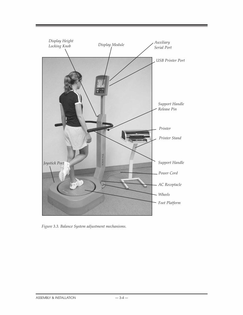
Figure 3.3. Balance System adjustment mechanisms.
CONTENTS
ASSEMBLY & INSTALLATION — 3-4 —
Display ModuleDisplay HeightLocking Knob
Support HandleRelease Pin
Support Handle
Printer
Printer Stand
Wheels
Foot Platform
AuxiliarySerial Port
USB Printer Port
Power Cord
AC Receptacle
Joystick Port
Prior to allowing any patient to use this device, make certain to read and comprehend this entiremanual. Ensure that you are completely familiar with all aspects of adjustment, training andtesting, as well as patient history. Be sure to adhere to the following clinical guidelines at alltimes when using this system.
NOTE: Never allow a patient to use the Balance System while unsupervised.
CONSIDERATIONS CLINIQUESAvant d’appliquer le systäme de stabilité à un patient, lire avec soin la présente notice. Il faut sefamiliariser avec tous les aspects de réglage, d’entraâneemnt et d’examen ainsi qu’avec ledossier du patient. Respecter les consigues indiquées ci-dessous lors de l’utilisation du systéme.
NOTA: Ne jamais laisser un patient sans surveillance sur le systéme de stabilité.
GENERAL CLINICAL CONSIDERATIONS1. All users should have a verbal understanding of the Balance System prior to stepping on thedevice.
2. To ensure patient safety, begin each session with the balance platform in the "locked" or staticposition.
NOTE: The Balance System automatically places the platform in the locked position when the unit isturned ON, or after a time period of three minutes when the system is not in use.
3. Adjust support rail and biofeedback display for patient comfort and safety.
4. When dealing with post-operative patients, ensure they possess adequate muscular control tostabilize the joint prior to placing them on the foot platform. Inadequate muscular control couldlead to increased joint translation.
5. When patients are working with their eyes closed, ensure that a clinician is ready to assist incase of loss of balance or use the optional patient support stand.
6. Since the entire lower extremity is required to work to stabilize the balance device, ensure thatsupporting structures above and below the joint are adequately strengthened prior to beginningrehabilitation on this device.
7. For optimal operation, ensure the patient is standing in the center of the platform.
8. Patients should progress from "hands-on" to "hands-off" the support handle. This will ensurethat new or unstable patients have an adequate understanding of the Balance System and willhelp protect the patient against sudden or unexpected movement of the platform.
9. Position the display so that the patient can look straight at it. This will help ensure good pos-ture during the test or exercise session.
10. There is a learning curve that must be considered when testing with this device. Clinicalresearch suggests three trials be performed prior to testing. For dynamic balance testing, the"default settings" are preselected with three trials per side. This should assist with the learningcurve and better average the data.
4. CLINICAL CONSIDERATIONS
— 4-1 — CLINICAL CONSIDERATIONS

CONSIDERATIONS CLINIQUES GENERALES1. Tout patient doit comrendre les principles du systàme de stabilité avant de s’y mettre.
2. Démarrer toutes les séances avec le platcau en position bloquéc.
NOTA: Lors de la misc sous tension, le systàme de stabilité se met automatiquement en positionbloquée. De la màme facan, si le systäme n’est pas utilisé pendant un intervalle de 3 minutes, ilse bloque.
3. Régler l’appui et l’ecran pour maximizer le confort et la sécurité du patient.
4. Pour des patients post-opératoires, vérifier avant de les faire monter sur le plateau qu’ils sontcapables de stabiliser leurs articulations. Un contrìle insuffisant pourrait les mettre à risque.
5. Si les patients travaillent les yeux fermés, il faut se tenir pràt à les aider ou mettre en placel’appui.
6. Puisque l’utilisation du plateau de stabilité sollicite toutes les articulations de l’extrémité,s’assurer que les cicatrisations sont suffisamment avancées pour supporter l’exercice.
7. Les résultats sont meilleurs avec le patient placé au milieu du plateau.
8. Les patients doivent démarrer avec l’appui et apprendre progressivement à ne plus s’enservir. De cette facon les patients développment leur compréhension du plateau de stabilité enminimisant les risques.
9. La courbe d’apprentissage du systäme peut influencer les résultats d’un examen. La littératureclinique suggàre qu’il faut réaliser trois examens à blanc avant de faire un examen définitif.
10. Régler l’écran droit devant les yeux du patient. Ceci aidera à maintenir une bonne positionpendant l’exmen ou l’entraånement.
ADDITIONAL CONSIDERATIONS FOR FALL PREVENTION PROGRAMSIn addition to the above, the following considerations should also be considered when workingwith patients in a fall prevention program.
1. It is strongly recommended that the Biodex Unweighing System be used in conjunction withbalance training/testing.
NOTE: The Biodex Unweighing System is intended to assist the patient who has balance deficits.Clinicians should not rely on this device to prevent falls.
2. Since the Biodex Balance System allows up to 20-degrees of surface tilt, begin with static orstability level 12 and progress as tolerated.
NOTE: The static setting is most stable, level one is least stable. Levels 12 to 1 provide a full 20 degrees ofsurface tilt.
3. Patients with extreme weakness or atrophy, especially of the lower extremity, should be close-ly monitored.
CONTENTS
CLINICAL CONSIDERATIONS — 4-2 —

NOTE: The ankle provides a critical source of sensory input, controlling the degree of sway in elderlypatients.
4. Repeat bouts of balance training where the joint is displaced nearly to its limits have beenshown to increase muscle tone, thus increasing muscle spindle sensitivity and enhancing thesomatosensory response.
AUTRES CONSIDERTIONS POUR DES PROGRAMMES DE PREVENTION DE CHUTESEn plus de ce qui précàde, les points évoqués ci-dessous doivent àtre étudiés dans le cadre d’untravail avec des patients dans un programme de preévention de chute.
1. L’utilisation du harnais de soutieu est recommendé lors de l’entraànement et de l ‘évaluationde la stabilité.
NOTA: Le harnais ne sert qu’à aider le patient à atteindre le déficit de stabilité. Le harnais seul ne peutpas prévenir des chutes.
2. Puisque le sysàme de stabilité permet une inclinaison de 20º, démarrer avec une stabilité 8 etavancer en fonction de la tolérance rencontrée.
NOTA: Le niveau 8 est le niveau le plus stable et le niveau l est le niveau le moins stable les deuxréglages permettent 20ºd’inclinaison.
3. Des patients particuliérement faibles ou atrophiées surtout dans les extrémités infériuresdoivent àtre surveillées de präs.
NOTA: La cheville fournit une source capitale d’informatioons sensorielles particuliérement importantespour les personnes Égées.
4. Des séances répétées d’entraânement de stabilité dans lesquelles l’articulation se déplaceproche de ses limites entraånent une augmentation de la tonalité musculaire, une sensibilitéaméliorée et des réponses somato-sensorielles plus vives.
CONTENTS
— 4-3 — CLINICAL CONSIDERATIONS
ORTHOPEDIC AND SPORTS MEDICINE1. Bilateral Balance Activities• Select desired training mode• Begin at level 12 or static and progress as tolerated• Begin with handrails in the upright position and progress to lowering them• Move platform as per training protocol• Use ball toss drill to increase eye/hand coordination
2. Unilateral Balance Activities• Select desired training mode• Begin at level 12 or static and progress as tolerated• Begin with handrails in the upright position and progress to lowering them• Move platform as per training protocol
3. Bilateral Upper Extremity Activities• Place both hands in a north/south, east/west and diagonal position• Select desired training mode• Begin with a stable platform and progress accordingly• Move platform as per training protocol• Begin on knees and progress to toes, to one knee, to one foot• Progress to unilateral balance, palm centered on the platform
FALL PREVENTION1. Bilateral Exercises• Begin with static level weight shifts• Progress to dynamic level (12) weight shifts• Use circular grid to demonstrate where tendency to fall occurs• Have patient perform both anterior/posterior and medial/lateral exercises
2. Unilateral Exercises• Have patient hold platform steady and illustrate how well the patient holds the platform stable• Different patterns (circles, anterior/posterior, medial/lateral) to increase strength of the lowerextremity
REFERENCE NOTES1. Caution must be noted when performing this activity. Ensure that the patient has the ability tohandle this challenging activity.
2. Ensure proper bilateral stabilization prior to unilateral stabilization.
3. Ensure that patient uses the handrails as needed.
4. Ensure that bilateral and unilateral static stability are adequate prior to progressing to unilat-eral dynamic stability.
5. The more unstable the platform (12 vs. one) the more challenging the activity will become.Ensure the patient uses the handrails at all times.
5. APPLICATIONS
— 5-1 — APPLICATIONS
NOTE DE RÉFÉRENCE1. Cette activité doit àtre entreprise avec précaution. S’assurer que le patient est capable deréaliser l’activité.
2. S’assurer d’une bonne stabilité bilatérale avant de commencer un travail sur la stabilité uni-latérale.
3. S’assurer que le patient sait utiliser l’appui correctement.
4. S’assurer que la stabilité bilatérale statique sur une seule jambe est adéquate avant deprocéder à la stabilité unilaterérale.
5. Plus le plateau est instable (8 équivaut à un réglage plus stable, le réglage l équivaut à unniveau moins stable), plus l’activité est difficile ä réaliser. S’assurer que la patient utilise l’appuià tout moment.
5. APPLICATIONS
APPLICATIONS — 5-2 —
The Biodex Balance System software program is easy to master. Simply follow the screenprompts as they lead you step-by-step through testing and training protocols or software utilityoptions. For each screen, active option keys are highlighted in boldface type. Touch the desiredon-screen key to make your selection. Option choices progress logically based on the selectionsmade.
ACCESSING THE MAIN MENU
To access the Balance System Main Menu:(See Figure 6.1.)
1. Press the <ON/STANDBY> button on the display to turn the Balance System ON. The MainMenu screen should now be displayed. This screen allows the user to select the Training, Testingor Utilities menus.
DISPLAY PANEL BUTTONS DESCRIBED(See Figure 6.2.)
There are only three buttons located on the Display Panel. These buttons operate as follows:
On/StandbyLocated at the bottom left corner of the display panel, the <ON/STANDBY> button is used toturn the system ON or to STANDBY (system is turned ON but display is still OFF).
• For ON, the Balance System Main Menu screen will appear on the display and the foot plat-form will automatically advance to the fully locked (stable) position if it is not already locked.
CAUTION: The foot platform does not automatically lock when the system is turned to STAND-BY. Thus, it is recommended that you first bring the platform to the fully locked position by press-ing the ON/STANDBY button to set the system to STANDBY.
ATTENTION: Le plateau ne roste pas dans la position bloquée en mode d’attente (STANDBY)pour cette raison il faut d’abord bloquer le plateau avant de sélectionner ce mode.
• For STANDBY, the display will turn OFF, all data will be lost, and power to the foot platformwill cease.
Start
The <Start> button is used to begin the selected training or testing protocol selected.
Stop
The <Stop> button is used to end the selected training or testing protocol selected.
6. GETTING STARTED
— 6-1 — GETTING STARTED
SCREEN KEYSThe following on-screen touch keys are consistent whenever they appear throughout the entireBalance System SD program.
<HOME>: Touch this key to return to the Main Menu.<NEXT>: Touch this key to advance to the next logical screen.<BACK>: Touch this key to return to the previous screen.<OK>: Touch this key to confirm selections or entries and advance to the next screen.
Figure 6.1. The Balance System Main Menu.
Figure 6.2 The Display Panel Keys.
CONTENTS
GETTING STARTED — 6-2 —
The training modes provide a simple means of setting up a training or exercise session. Sixinteractive game-like training modes are provided. These allow for fast patient setups, less for-mal protocols than the testing routines, and the ability to change stability level from very unsta-ble to static during the actual training session. All five training modes can be customized to pro-vide specific rehab goals with the on-screen grid and score-keeping functions used to both helpmotivate users and keep them focused on the task at hand.
In training mode, only the most basic parameters are addressed. If desired, a pre-existing patientcan be recalled from the Test/Rehab Results option in Patient Maintenance menu to allow forquick and easy repeat of a training or test session. The print screen function will allow the userto generate a printout of training results.
Training results can also be saved and recalled for later use by touching the <Save> icon on theresults screen following any training session. A patient name is required to save the results. If nopre-existing name is available, the name entry screen will be displayed. Fill out the patient infor-mation and touch <Save> to record the training result numeric values, along with patient footposition on the platform.
To recall a patient and repeat an exercise session, select the desired patient from the PatientManagement screen (see chapter 11, System Utilities) and touch <Repeat>. The Position Patientscreen with previous values is presented so the patient can be easily repositioned exactly as inthe previous training session.
Training mode formats include: postural stability, limits of stability, weight shift, maze control,random control and percent weight bearing training as described in the following sections.
Figure 7.1. The Training Menu screen provides access to the Postural Stability, Limits of Stability,Weight Shift, Maze Control, % Weight Bearing and Random Control training modes.
7. THE TRAINING MODES
— 7-1 — THE TRAINING MODES
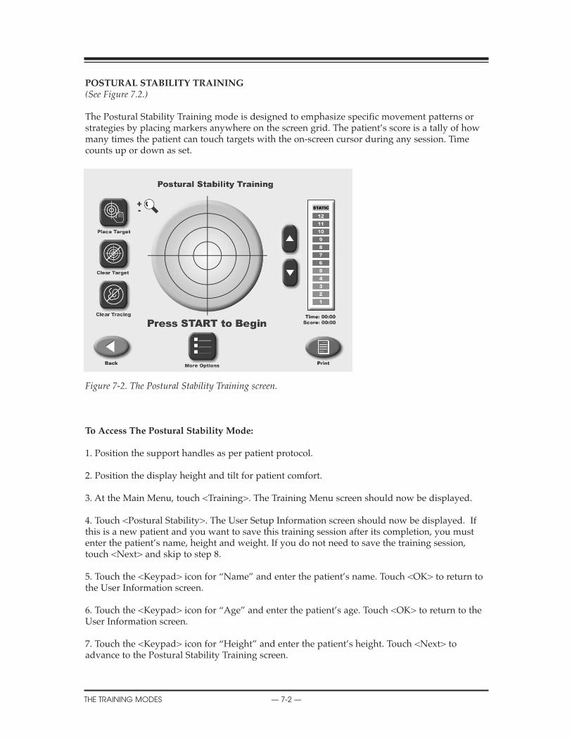
POSTURAL STABILITY TRAINING(See Figure 7.2.)
The Postural Stability Training mode is designed to emphasize specific movement patterns orstrategies by placing markers anywhere on the screen grid. The patient’s score is a tally of howmany times the patient can touch targets with the on-screen cursor during any session. Timecounts up or down as set.
Figure 7-2. The Postural Stability Training screen.
To Access The Postural Stability Mode:
1. Position the support handles as per patient protocol.
2. Position the display height and tilt for patient comfort.
3. At the Main Menu, touch <Training>. The Training Menu screen should now be displayed.
4. Touch <Postural Stability>. The User Setup Information screen should now be displayed. Ifthis is a new patient and you want to save this training session after its completion, you mustenter the patient’s name, height and weight. If you do not need to save the training session,touch <Next> and skip to step 8.
5. Touch the <Keypad> icon for “Name” and enter the patient’s name. Touch <OK> to return tothe User Information screen.
6. Touch the <Keypad> icon for “Age” and enter the patient’s age. Touch <OK> to return to theUser Information screen.
7. Touch the <Keypad> icon for “Height” and enter the patient’s height. Touch <Next> toadvance to the Postural Stability Training screen.
7. THE TRAINING ROUTINE
THE TRAINING MODES — 7-2 —

8. At the Postural Stability Training screen, touch <Place Target> and then touch the screen loca-tion where you would like a target to be placed. Repeat this process to place up to nine targetson the screen.
9. To clear any misplaced or unwanted targets, touch <Clear Target>. Each time this key ispressed, the most recent target added to the screen will be removed.
10. Touch <More Options> to advance to the Postural Stability Training Options screen ifdesired.Here you can set the total time for the exercise, enter initial and ending platform stability set-tings, and turn tracing ON/OFF. Touch <OK> to confirm your selections and return to thePostural Stability Training Options screen, or <Cancel> to return to the Postural StabilityTraining Options screen without making changes.
• Use the <�> or <�> keys to set the total time in 10-second increments (during the routine thesystem will count down from the time setting selected).
NOTE: Total time must be set before you can set beginning and ending platform stability.
• To set initial platform stability, touch the appropriate key and then enter the setting from thekeypad displayed (static, 12 is most stable, 1 is least stable). Touch <OK> to return to the PosturalStability Training Options screen and set the ending platform stability in the same manner.
• To turn tracing ON/OFF, touch <Tracing> to toggle between choices.
11. At the Postural Stability Training screen touch the <�> or <�> keys to select the desiredplatform stability if not already selected (static, 12 is most stable, 1 is least stable).
12. Explain the training protocol to the patient and then press <Start> on the display to begin thetraining session. The Stability Training grid on the screen charts the patient’s stability performancethrough the course of the training session (touch the <Magnifying Glass> to enlarge the screen ifdesired). The Elapsed Time from the start of the training session is shown at the top right of thedisplay while the stability level is illustrated by a bar graph in the upper right-hand corner. Notethat the stability level of the foot platform can be changed at any time during the exercise session.
NOTE: If you have selected to enlarge the screen by touching the <Magnifying Glass>, you must returnto the normal viewing screen format to make any changes.
NOTE: As the patient moves the platform during the training session, a "tracing" feature records theroute of the cursor on the grid. This feature can be used to visually illustrate a patient’s positioningthroughout the routine, or as a target, i.e., asking the patient to "trace" a letter, square, circle, etc.
13. At any time during the training session, the "tracing" can be erased by pressing <ClearTracing>.
14. To stop the training session at any time, press <Stop> on the display. The system will stopgathering data and the platform will advance to the locked position.
15. When you are finished reviewing the training screen, touch <Print> to print the screen,or <Save Results> to save the training session (numeric data only).
16. After printing or reviewing the screen, press <Start> to immediately begin another trainingsession using the same parameters, or press <Back> to return to the Training Setup screen.
CONTENTS
— 7-3 — THE TRAINING MODES

LIMITS OF STABILITY (LOS) TRAINING ROUTINE(See Figure 7.3.)
The Limits of Stability Training screen is designed to challenge the user to move through amovement pattern consistent with the sway envelope. The sway envelope is that area a personcan move their COG within their base of support. It is approximated from vertical as 8 degreesto one side, 8 degrees to the other (total of 16 degrees of sway,) and 8 degrees forward and 4degrees back (12 degrees total). Limits of Stability training and testing are based on challengingthe patient within this sway envelope. Testing is usually done at 75% LOS, which is the moder-ate skill level. Easy skill level is 50% and hard skill level is 100% of the sway envelop.
Scoring percentage-based and reflects the directional accuracy of the movement to theblinking targets (see Appendix B-1) time counts up.
Figure 7.3. The Limits of Stability (LOS) Training Screen.
To Access The Limits of Stability Training Mode:
1. Position the support handles as per patient protocol.
2. Position the display height and tilt for patient comfort.
3. At the Main Menu, touch <Training>. The Training Menu screen should now be displayed.
4. Touch <Limits of Stability>. The User Setup Information screen should now be displayed. Ifthis is a new patient and you want to save this training session after its completion, you mustenter the patient’s name, height and weight. If you do not need to save the training session,touch <Next> and skip to step 8.
5. Touch the <Keypad> icon for “Name” and enter the patient’s name. Touch <OK> to return tothe User Information screen.
6. Touch the <Keypad> icon for “Age” and enter the patient’s age. Touch <OK> to return to theUser Information screen.
CONTENTS
THE TRAINING MODES — 7-4 —
7. Touch the <Keypad> icon for “Height” and enter the patient’s height. Touch <Next> toadvance to the Limits of Stability Training screen.
8. At the Limits of Stability Training screen, touch <Stance> to toggle though the patient stancepositions until the desired choice, right leg, left leg or both legs, is displayed.
9. Touch <Skill Level> to tighten or widen the spread between targets. Three skill levels are avail-able from which to choose. Touch <Skill Level> until the desired target configuration is displayed.
10. If desired, touch <Clear Tracing> to remove any tracing that remains on the screen from aprevious exercise session.
11. Touch <More Options> to advance to the Limits of Stability Training Options screen ifdesired. Here you can set the Limits of Stability Hold Time for the exercise and turn TracingON/OFF. Touch <OK> to confirm your selections and return to the Limits of Stability screen, or<Cancel> to return to the Limits of Stability screen without making changes.
• To set a Limits of Stability Hold Time, use the <�> or <�> keys to scroll to the desired set-ting. Hold times range from .025 to 5 seconds.
• To turn tracing ON/OFF, touch <Tracing> to toggle between choices.
12. At the Limits of Stability Training screen touch the <�> or <�> keys to select the desiredplatform stability (static, 12 is most stable, 1 is least stable).
13. Explain the training protocol to the patient, then press <Start> to begin the LOS training ses-sion. The LOS Training screen reflects the patient’s stability performance through the course ofthe LOS training session. The Elapsed Time from the start of the training session is shown at thetop right of the display while the stability level is illustrated by a bar graph. A running patientscore is also provided in the upper right corner. Note that the stability level of the foot platformcan be changed at any time during the exercise session.
NOTE: If you have selected to enlarge the screen by touching the <Magnifying Glass>, you must returnto the normal viewing screen format to make any changes.
14. At any time during the training session, the "tracing" can be erased by pressing <Clear Tracing>.
15. To stop the training session at any time, press <Stop> on the display. The system will stopgathering data and the platform will advance to the locked position.
16. When you are finished reviewing the training screen, touch <Print> to print the screen,or <Save Results> to save the training session (numeric data only).
17. After printing or reviewing the screen, press <Start> to immediately begin another trainingsession using the same parameters, or press <Back> to return to the Training Setup screen.
8. TESTING A PATIENT
— 7-5 — THE TRAINING MODES

WEIGHT SHIFT TRAINING(See Figure 7.4)
This training mode allows for exercise in the most basic of activities weight shifting. The patienthas the ability to shift weight in medial/lateral, anterior/posterior and diagonal planes. This canbe done with both static and dynamic settings. During this training routine the target zone,defined by two parallel lines, can be rotated to any of three positions while the amount of excur-sion within the target area can be modified to allow for the most limited to most difficult degreeof weight shifting. To reposition the target zone hit lines at any time, simply touch the desiredline and re-touch the screen where you want the line to be relocated.
Scoring is percentage-based and equals net good hits/total target hits. If you cross the boundary,that counts against the good hit total. All outside boundary hits are subtracted from the totalamount of target hits. This value equals the net good hits.
For example: Enter 10 as the # of target hits. There were 4 times the cursor went outside theboundary. 10-4 = 6 good hits. Score = 6/10 or 60%.
For weight shift training the time value always counts up.
NOTE: A wall hit is counted as one hit within the path to the target hit.
Figure 7.4. The Weight Shift Training Screen.
To Access The Weight Shift Training Mode:
1. Position the support handles as per patient protocol.
2. Position the display height and tilt for patient comfort.
3. At the Main Menu, touch <Training>. The Training Menu screen should now be displayed.
4. Touch <Weight Shift >. The User Setup Information screen should now be displayed. If this isa new patient and you want to save this training session after its completion, you must enter thepatient’s name, height and weight. If you do not need to save the training session, touch <Next>and skip to step 8.
CONTENTS
THE TRAINING MODES — 7-6 —
Target zone hit lines
5. Touch the <Keypad> icon for “Name” and enter the patient’s name. Touch <OK> to return tothe User Information screen.
6. Touch the <Keypad> icon for “Age” and enter the patient’s age. Touch <OK> to return to theUser Information screen.
7. Touch the <Keypad> icon for “Height” and enter the patient’s height. Touch <Next> toadvance to the Weight Shift Training screen.
8. At the Weight Shift Training screen, touch <Rotate Target > to toggle through the three patienttarget positions until the desired rotation is displayed on the grid.
9. Touch <Skill Level> to enlarge or decrease the target box size. Three skill levels are availablefrom which to choose. Touch <Skill Level> until the desired target configuration is displayed.
10. If desired, touch <Clear Tracing> to remove any tracing that remains on the screen from aprevious exercise session.
11. Touch <More Options> to advance to the Weight Shift Training Options screen if desired. Hereyou can set the total hits for the exercise (default = 60), set platform stability and turn tracingON/OFF. Touch <OK> to confirm your selections and return to the Weight Shift Training Optionsscreen, or <Cancel> to return to the Weight Shift Training Options screen without making changes.
• Use the <�> or <�> keys to set the total hits.
NOTE: Total hits must be set before you can set beginning and ending platform stability.
• To set initial platform stability, touch the appropriate key and then enter the setting from thekeypad displayed (static, 12 is most stable, 1 is least stable). Touch <OK> to return to the WeightShift Training Options screen and set the ending platform stability in the same manner.
• To turn tracing ON/OFF, touch <Tracing> to toggle between choices.
12. At the Weight Shift Training screen touch the <�> or <�> keys to select the desired platformstability if not already selected (static, 12 is most stable, 1 is least stable).
13. Explain the training protocol to the patient and then press <Start> on the display to beginthe training session. The Stability Training grid on the screen charts the patient’s stability per-formance through the course of the training session (touch the <Magnifying Glass> to enlargethe screen if desired). The Elapsed Time from the start of the training session is shown at the topright of the display while the stability level is illustrated by a bar graph in the upper right cor-ner. A running patient score is also provided in the upper right corner. Note that the stabilitylevel of the foot platform can be changed at any time during the exercise session.
NOTE: If you have selected to enlarge the screen by touching the <Magnifying Glass>, you must returnto the normal viewing screen format to make any changes.
14. At any time during the training session, the "tracing" can be erased by pressing <Clear Tracing>.
15. To stop the training session at any time, press <Stop> on the display. The system will stopgathering data and the platform will advance to the locked position.
16. When you are finished reviewing the Weight Shift Training screen, touch <Print> to print thescreen, or <Save Results> to save the training session (numeric data only).
17. After printing or reviewing the screen, press <Start> to immediately begin another trainingsession using the same parameters, or press <Back> to return to the Training Setup screen.
CONTENTS
— 7-7 — THE TRAINING MODES

MAZE CONTROL TRAINING(See Figure 7.5.)
This mode allows the patient to follow a reproducible pattern of movement throughout a mazein both static and dynamic environments. Three skill levels allow the maze to be modified tocreate a simple or more difficult environment for the patient to navigate through. Change theplatform from static mode to dynamic mode to facilitate progression. Time counts up or downas set.
Scoring is percentage-based on the net good hits/total target hits. If the cursor hits the boundarythat hit is subtracted from the total possible amount of good hits.
• Easiest maze has 28 total targets, 14 in each direction• Moderate has 36 targets, 18 in each direction• Most difficult has 72 targets, 36 in each direction
In the case of the easiest maze. If the wall is hit 6 times the resulting score will be 22/28 = 78%
Figure 7.5. The Maze Control Training screen.
To Access The Maze Control Mode:
1. Position the support handles as per patient protocol.
2. Position the display height and tilt for patient comfort.
3. At the Main Menu, touch <Training>. The Training Menu screen should now be displayed.
4. Touch <Maze Control >. The User Setup Information screen should now be displayed. If thisis a new patient and you want to save this training session after its completion, you must enterthe patient’s name, height and weight. If you do not need to save the training session, touch<Next> and skip to step 8.
CONTENTS
THE TRAINING MODES — 7-8 —
5. Touch the <Keypad> icon for “Name” and enter the patient’s name. Touch <OK> to return tothe User Information screen.
6. Touch the <Keypad> icon for “Age” and enter the patient’s age. Touch <OK> to return to theUser Information screen.
7. Touch the <Keypad> icon for “Height” and enter the patient’s height. Touch <Next> toadvance to the Maze Control Training screen.
8. Touch <Skill Level> to increase or decrease the number of targets displayed on the graph.Three skill levels are available from which to choose. Touch <Skill Level> until the desired targetconfiguration is displayed.
9. If desired, touch <Clear Tracing> to remove any tracing that remains on the screen from a pre-vious exercise session.
10. Touch <More Options> to advance to the Maze Control Training Options screen if desired.
Here you can set the total time for the exercise, enter initial and ending platform stability set-tings, and turn tracing ON/OFF. Touch <OK> to confirm your selections and return to the MazeControl Training Options screen, or <Cancel> to return to the Maze Control Training Optionsscreen without making changes.
• Use the <�> or <�> keys to set the total hits.
NOTE: Total time must be set before you can set beginning and ending platform stability.
• To set initial platform stability, touch the appropriate key and then enter the setting from thekeypad displayed (static, 12 is most stable, 1 is least stable). Touch <OK> to return to the MazeControl Training Options screen and set the ending platform stability in the same manner.
• To turn tracing ON/OFF, touch <Tracing> to toggle between choices.
11. At the Maze Control Training screen touch the <�> or <�> keys to select the desired plat-form stability if not already selected (static, 12 is most stable, 1 is least stable).
12. Explain the training protocol to the patient and then press <Start> on the display to beginthe training session. The Stability Training grid on the screen charts the patient’s stability per-formance through the course of the training session (touch the <Magnifying Glass> to enlargethe screen if desired). The Elapsed Time from the start of the training session is shown at the topright of the display while the stability level is illustrated by a bar graph in the upper right cor-ner. A running patient score is also provided in the upper right corner. Note that the stabilitylevel of the foot platform can be changed at any time during the exercise session.
NOTE: If you have selected to enlarge the screen by touching the <Magnifying Glass>, you must returnto the normal viewing screen format to make any changes.
13. At any time during the training session, the "tracing" can be erased by pressing <Clear Tracing>.
14. To stop the training session at any time, press <Stop> on the display. The system will stopgathering data and the platform will advance to the locked position.
15. When you are finished reviewing the Maze Control Training screen, touch <Print> to printthe screen, or <Save Results> to save the training session (numeric data only).
16. After printing or reviewing the screen, press <Start> to immediately begin another trainingsession using the same parameters, or press <Back> to return to the Training Setup screen.
CONTENTS
— 7-9 — THE TRAINING MODES
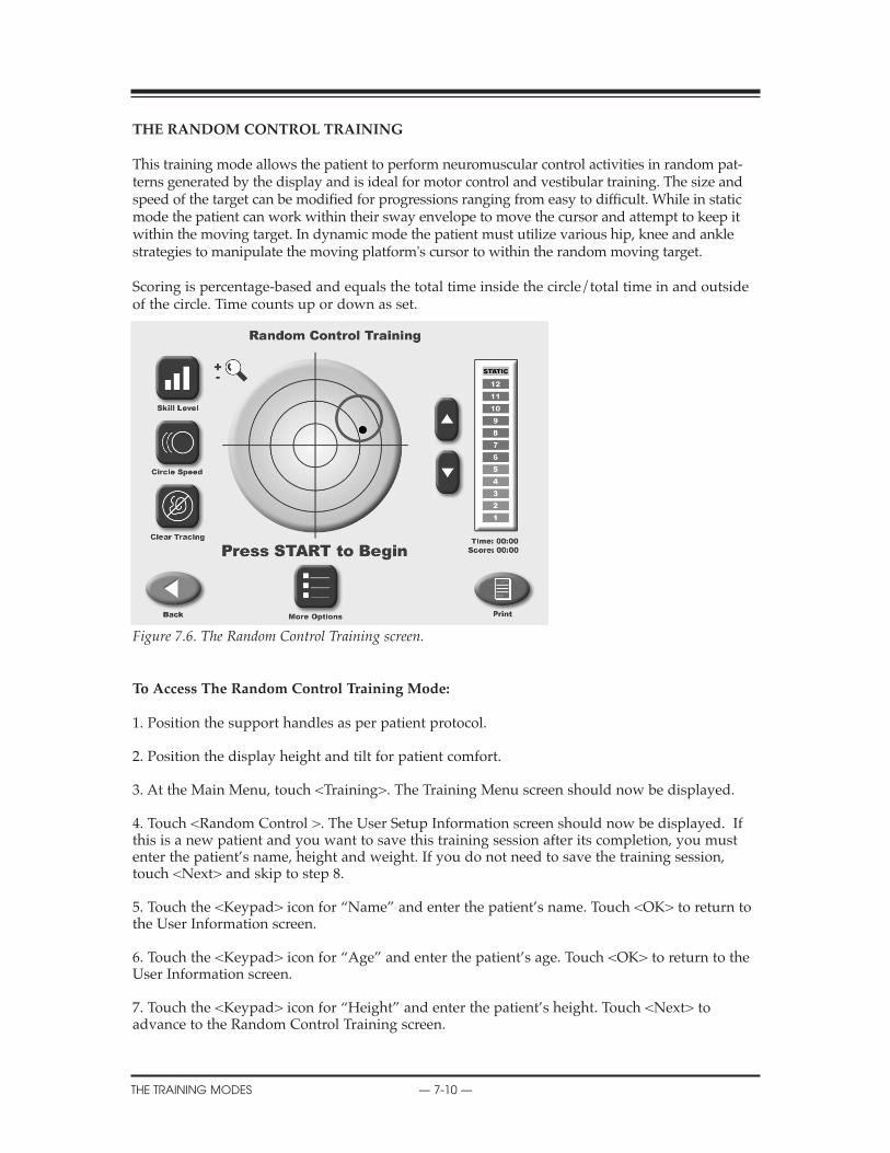
THE RANDOM CONTROL TRAINING
This training mode allows the patient to perform neuromuscular control activities in random pat-terns generated by the display and is ideal for motor control and vestibular training. The size andspeed of the target can be modified for progressions ranging from easy to difficult. While in staticmode the patient can work within their sway envelope to move the cursor and attempt to keep itwithin the moving target. In dynamic mode the patient must utilize various hip, knee and anklestrategies to manipulate the moving platform's cursor to within the random moving target.
Scoring is percentage-based and equals the total time inside the circle/total time in and outsideof the circle. Time counts up or down as set.
Figure 7.6. The Random Control Training screen.
To Access The Random Control Training Mode:
1. Position the support handles as per patient protocol.
2. Position the display height and tilt for patient comfort.
3. At the Main Menu, touch <Training>. The Training Menu screen should now be displayed.
4. Touch <Random Control >. The User Setup Information screen should now be displayed. Ifthis is a new patient and you want to save this training session after its completion, you mustenter the patient’s name, height and weight. If you do not need to save the training session,touch <Next> and skip to step 8.
5. Touch the <Keypad> icon for “Name” and enter the patient’s name. Touch <OK> to return tothe User Information screen.
6. Touch the <Keypad> icon for “Age” and enter the patient’s age. Touch <OK> to return to theUser Information screen.
7. Touch the <Keypad> icon for “Height” and enter the patient’s height. Touch <Next> toadvance to the Random Control Training screen.
CONTENTS
THE TRAINING MODES — 7-10 —

8. At the Random Control Training screen, the target circle should be flashing in the center of thestability grid. Touch <Circle Speed > to toggle though the three target circle speeds until the tar-get circle flashes at the desired speed.
9. Touch <Skill Level> to enlarge or decrease the target circle size. Three skill levels are availablefrom which to choose. Touch <Skill Level> until the desired target size is displayed.
10. If desired, touch <Clear Tracing> to remove any tracing that remains on the screen from aprevious exercise session.
11. Touch <More Options> to advance to the Random Control Training Options screen ifdesired. Here you can set the total time for the exercise, enter initial and ending platform stabili-ty settings, and turn tracing ON/OFF. Touch <OK> to confirm your selections and return to theRandom Control Training Options screen, or <Cancel> to return to the Random Control TrainingOptions screen without making changes.
• Use the <�> or <�> keys to set the total time in 10-second increments (during the routine thesystem will count down from the time setting selected).
NOTE: Total time must be set before you can set beginning and ending platform stability.
• To set initial platform stability, touch the appropriate key and then enter the setting from thekeypad displayed (static, 12 is most stable, 1 is least stable). Touch <OK> to return to the RandomControl Training Options screen and set the ending platform stability in the same manner.
• To turn tracing ON/OFF, touch <Tracing> to toggle between choices.
12. At the Random Control Training screen touch the <�> or <�> keys to select the desiredplatform stability if not already selected (static, 12 is most stable, 1 is least stable).
13. Explain the training protocol to the patient and then press <Start> on the display to beginthe training session. The Stability Training grid on the screen charts the patient’s stability per-formance through the course of the training session (touch the <Magnifying Glass> to enlargethe screen if desired). The Elapsed Time from the start of the training session is shown at the topright of the display while the stability level is illustrated by a bar graph in the upper right cor-ner. A running patient score is also provided in the upper right corner. Note that the stabilitylevel of the foot platform can be changed at any time during the exercise session.
NOTE: If you have selected to enlarge the screen by touching the <Magnifying Glass>, you must returnto the normal viewing screen format to make any changes.
14. At any time during the training session, the "tracing" can be erased by pressing <Clear Tracing>.
15. To stop the training session at any time, press <Stop> on the display. The system will stopgathering data and the platform will advance to the locked position.
16. When you are finished reviewing the Random Control Training screen, touch <Print> toprint the screen, or <Save Results> to save the training session (numeric data only).
17. After printing or reviewing the screen, press <Start> to immediately begin another trainingsession using the same parameters, or press <Back> to return to the Training Setup screen.
CONTENTS
— 7-11 — THE TRAINING MODES
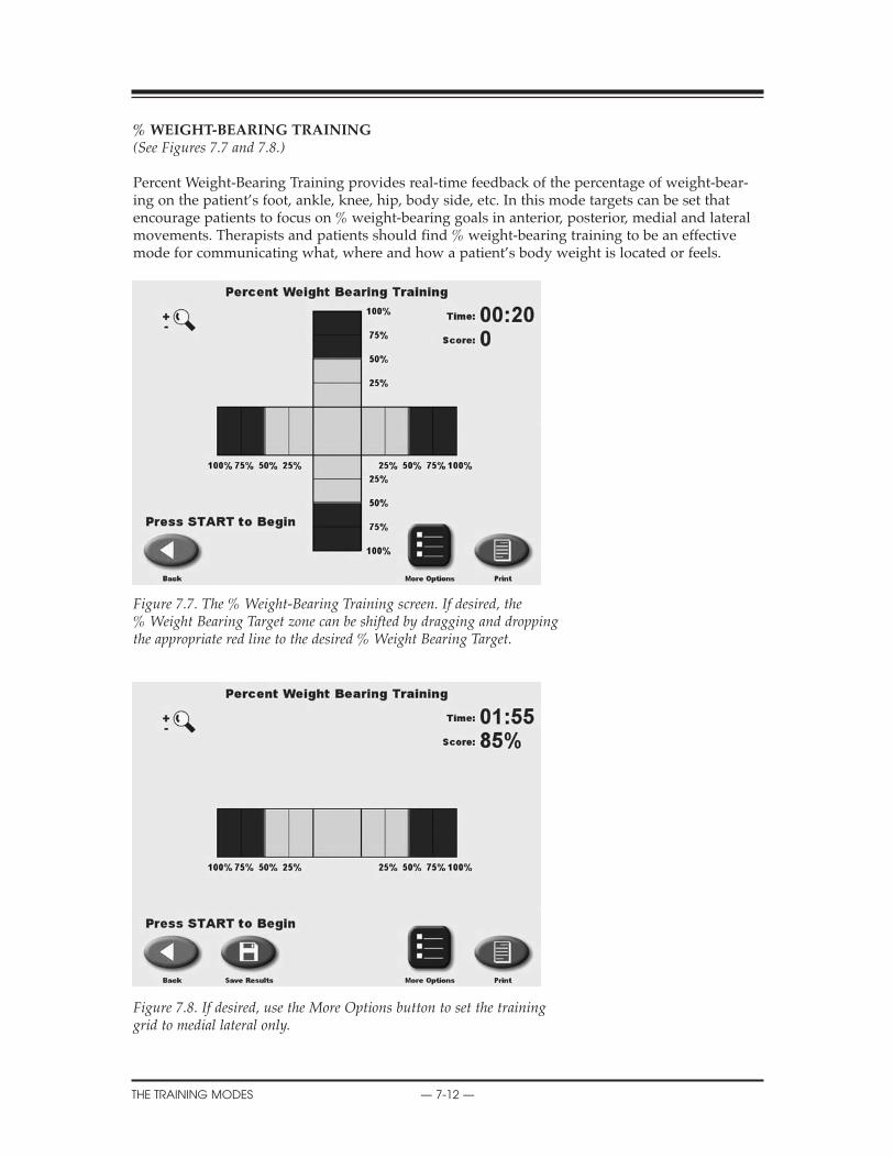
%WEIGHT-BEARING TRAINING(See Figures 7.7 and 7.8.)
Percent Weight-Bearing Training provides real-time feedback of the percentage of weight-bear-ing on the patient’s foot, ankle, knee, hip, body side, etc. In this mode targets can be set thatencourage patients to focus on % weight-bearing goals in anterior, posterior, medial and lateralmovements. Therapists and patients should find % weight-bearing training to be an effectivemode for communicating what, where and how a patient’s body weight is located or feels.
Figure 7.7. The % Weight-Bearing Training screen. If desired, the% Weight Bearing Target zone can be shifted by dragging and droppingthe appropriate red line to the desired % Weight Bearing Target.
Figure 7.8. If desired, use the More Options button to set the traininggrid to medial lateral only.
CONTENTS
THE TRAINING MODES — 7-12 —
To Access The % Weight-Bearing Training Mode:
NOTE: % Weight-Bearing is used with the platform in static mode only.
1. Position the support handles as per patient protocol.
2. Position the display height and position for patient comfort.
3. At the Main Menu, touch <Training>. The Training Menu screen should now be displayed.
4. Touch <% Weight Bearing>. The User Setup Information screen should now be displayed. Ifthis is a new patient and you want to save this training session after its completion, you mustenter the patient’s name, height and weight. If you do not need to save the training session,touch <Next> and skip to step 8.
5. Touch the <Keypad> icon for “Name” and enter the patient’s name. Touch <OK> to return tothe User Setup Information screen.
6. Touch the <Keypad> icon for “Age” and enter the patient’s age. Touch <OK> to the return tothe User Setup Information screen.
7. Touch the <Keypad> icon for “Height” and enter the patient’s height. Touch <Next> toadvance to the Position Patient screen.
8. Position the patient on the system and explain the training protocol. Press <Start> on the dis-play to activate the cursor and have the patient move the cursor to the center point on the grid.
9. Touch <Record> to bring up the Position Patient Entry screen. Using the keypads, enter thepatient’s left foot, left heel, right foot and right heel positions using the midline of the foot andthe platform grid as reference points. Touch <Next> to advance to the % Weight BearingTraining screen.
10. The % Weight Bearing Training screen displays a Medial Lateral/Anterior Posterior grid. Ifyou would prefer a Medial Lateral only grid, touch <More Options>. The More Options screenalso allows the clinician to set an end by time value. Touch <OK> after making changes toreturn to the % Weight Bearing Training screen.
11. If desired, shift the red % Weight Bearing target zone by touching and dragging the appro-priate red line to the desired % Weight Bearing target.
12. Explain the training protocol to the patient and then press <Start> on the display to beginthe training session. The grid charts the patient’s weight-bearing performance though the courseof the training session (touch the <Magnifying Glass> to enlarge the screen if desired.) TheElapsed Time from the start of the session is shown at the top right of the display. A runningpatient score is provided in the upper right corner.
NOTE: If you have selected to enlarge the screen by touching the <Magnifying Glass>, you must returnto the normal viewing screen format to make any changes.
13. To stop the training session at any time, press <Stop> on the display. The system will stopgathering data.
CONTENTS
— 7-13 — THE TRAINING MODES

14. When you are finished reviewing the % Weight Bearing Training screen, touch <Print> toprint the screen, or <Save Results> to save the training session (numeric data only).
16. After printing or reviewing the screen, press <Start> to immediately begin another trainingsession using the same parameters, or press <Back> to return to the Training Setup screen.
NOTE: Scoring is the % time spent within the target range.
CONTENTS
THE TRAINING MODES — 7-14 —
The Biodex Balance System SD allows clinicians to assess a patient’s neuromuscular control in aclosed-chain, multi-plane test by quantifying the ability of the patient to maintain dynamic uni-lateral or bilateral postural stability on either a static or unstable surface. The degree of surfaceinstability is controlled by the system’s microprocessor-based actuator. The clinician selects thetest duration, stability level and protocol.
In a dynamic test, once the session beings the patient’s ability to control the platform angle isquantified as a variance from the locked (level) position, as well as degrees of deflection overtime. A large variance may be indicative of poor neuromuscular response. Further insight intospecific neuromuscular activation patterns is realized with the quantification of anteri-or/posterior and medial/lateral platform tilt. Predictive Values and Comparative (Bilateral)Reports are available to chart the patient’s performance. Bilateral comparisons quickly docu-ment differences between each lower extremity.
Static testing measures the angular excursion of the patient's center of gravity. Body height mustcome into play for static measures. A person's Center of Gravity (COG) is approximately 55% oftheir height. Based on the selected height an appropriate static measure scaling is applied.Testing in this mode is ideal for baseline testing for movement disorder, vestibular dysfunctionand orthopedic patients. Good static testing scores can lead to a progression into dynamic test-ing and training.
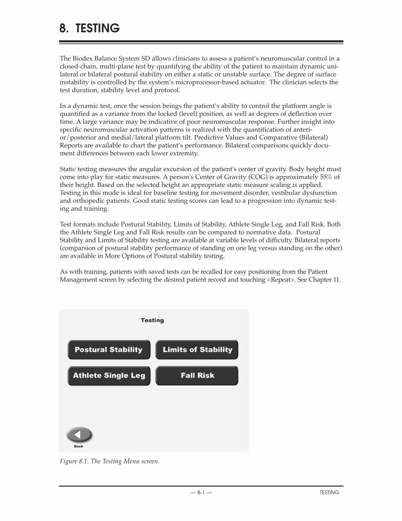
Test formats include Postural Stability, Limits of Stability, Athlete Single Leg, and Fall Risk. Boththe Athlete Single Leg and Fall Risk results can be compared to normative data. PosturalStability and Limits of Stability testing are available at variable levels of difficulty. Bilateral reports(comparsion of postural stability performance of standing on one leg versus standing on the other)are available in More Options of Postural stability testing.
As with training, patients with saved tests can be recalled for easy positioning from the PatientManagement screen by selecting the desired patient record and touching <Repeat>. See Chapter 11.
Figure 8.1. The Testing Menu screen.
8. TESTING
— 8-1 — TESTING
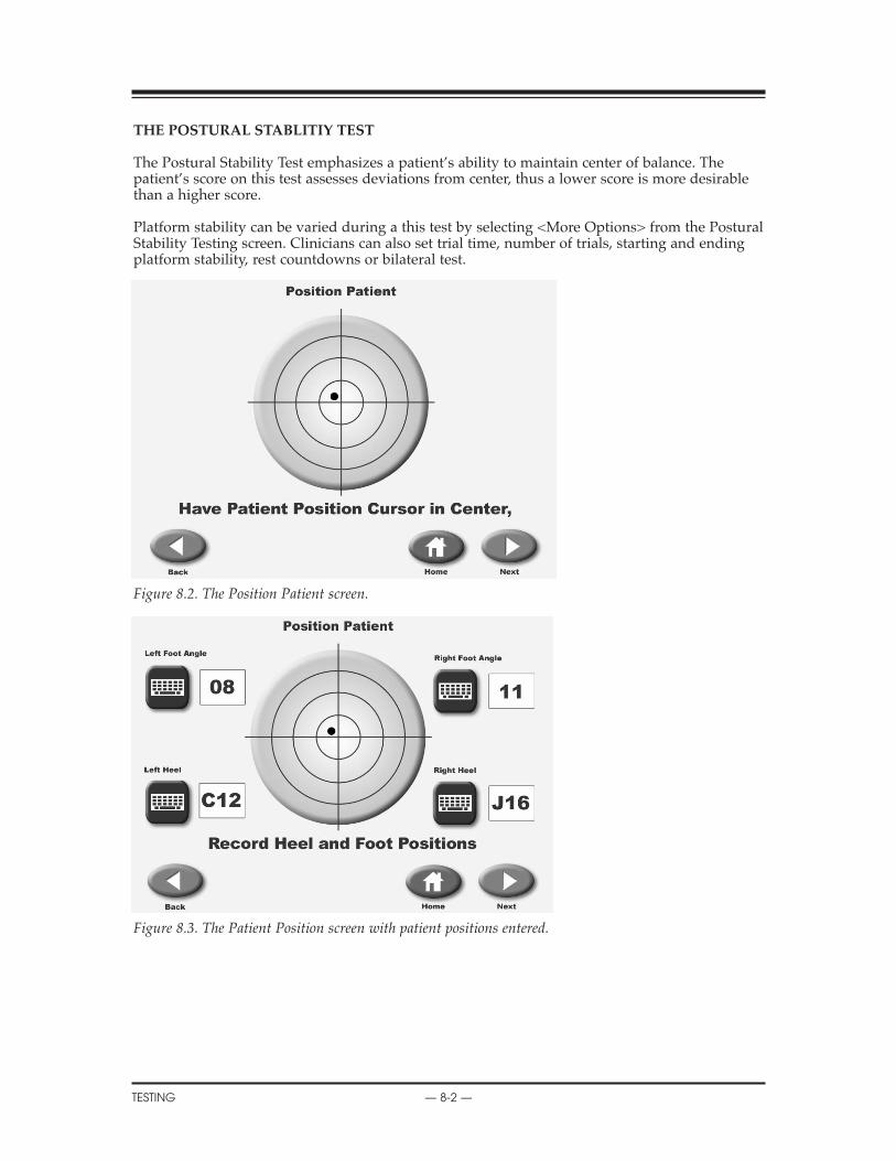
THE POSTURAL STABLITIY TEST
The Postural Stability Test emphasizes a patient’s ability to maintain center of balance. Thepatient’s score on this test assesses deviations from center, thus a lower score is more desirablethan a higher score.
Platform stability can be varied during a this test by selecting <More Options> from the PosturalStability Testing screen. Clinicians can also set trial time, number of trials, starting and endingplatform stability, rest countdowns or bilateral test.
Figure 8.2. The Position Patient screen.
Figure 8.3. The Patient Position screen with patient positions entered.
CONTENTS
TESTING — 8-2 —
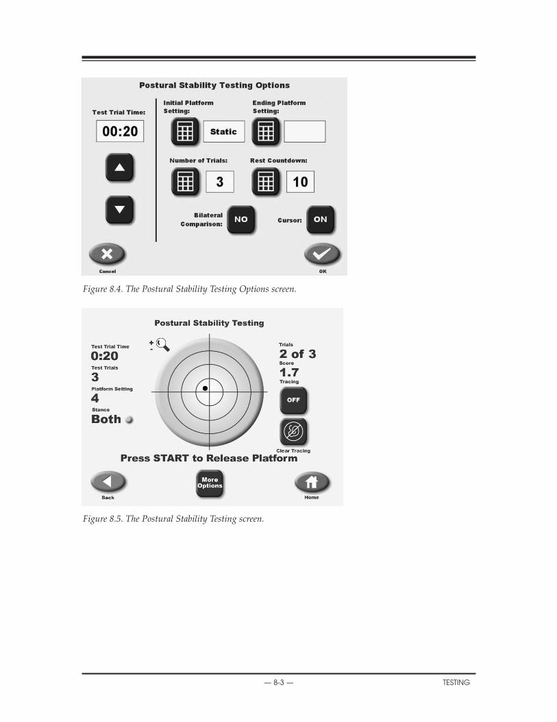
Figure 8.4. The Postural Stability Testing Options screen.
Figure 8.5. The Postural Stability Testing screen.
CONTENTS
— 8-3 — TESTING
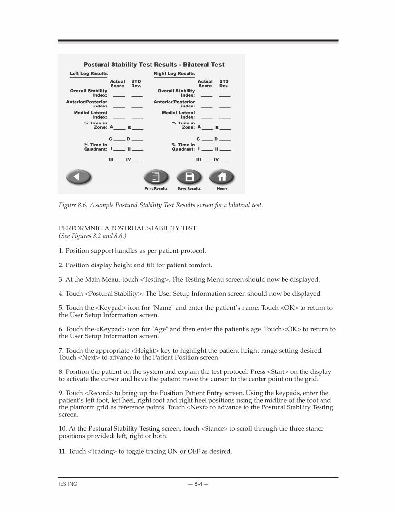
Figure 8.6. A sample Postural Stability Test Results screen for a bilateral test.
PERFORMNIG A POSTRUAL STABILITY TEST(See Figures 8.2 and 8.6.)
1. Position support handles as per patient protocol.
2. Position display height and tilt for patient comfort.
3. At the Main Menu, touch <Testing>. The Testing Menu screen should now be displayed.
4. Touch <Postural Stability>. The User Setup Information screen should now be displayed.
5. Touch the <Keypad> icon for "Name" and enter the patient’s name. Touch <OK> to return tothe User Setup Information screen.
6. Touch the <Keypad> icon for "Age" and then enter the patient’s age. Touch <OK> to return tothe User Setup Information screen.
7. Touch the appropriate <Height> key to highlight the patient height range setting desired.Touch <Next> to advance to the Patient Position screen.
8. Position the patient on the system and explain the test protocol. Press <Start> on the displayto activate the cursor and have the patient move the cursor to the center point on the grid.
9. Touch <Record> to bring up the Position Patient Entry screen. Using the keypads, enter thepatient’s left foot, left heel, right foot and right heel positions using the midline of the foot andthe platform grid as reference points. Touch <Next> to advance to the Postural Stability Testingscreen.
10. At the Postural Stability Testing screen, touch <Stance> to scroll through the three stancepositions provided: left, right or both.
11. Touch <Tracing> to toggle tracing ON or OFF as desired.
CONTENTS
TESTING — 8-4 —

12. Touch <Clear Tracing> to clear any tracing that remains from previous tests.
13. Touch <More Options> to advance to the Postural Stability Test Options screen if desired.Here you can set the Test Trial Time, enter initial and ending platform stability settings, enter thenumber of trials, enter the Rest Countdown, or toggle bilateral comparison to "Yes" or "No" andenter the Rest Countdown. You can also toggle the cursor ON/OFF. Touch <OK> to confirmyour selections and return to the Postural Stability Testing screen.
• Use the <�> or <�> keys to set the total time in five-second increments (during the routinethe system will count down from the time setting selected).
NOTE: Total time must be set before you can set beginning and ending platform stability.
• To set initial or ending platform stability (static, 12 is most stable, 1 is least stable,) touch theappropriate key and then enter the setting from the keypad displayed. Touch <OK> to return tothe Postural Stability Testing Options screen and set the ending platform stability in the samemanner.
• To set the number of trials or rest countdown, touch the appropriate key and then enter thesetting from the keypad displayed.
• To turn the cursor ON/OFF, touch <Cursor> to toggle between choices.
• To toggle bilateral comparison "Yes" or "No," touch <Bilateral Comparison>.
14. Press <Start> to release the platform (if not static) and activate the Postural Stability Test screen.
15. With the patient ready to begin the test, touch <Collect Data>. The screen will provide a three-second countdown before beginning the first of three test trials. The display screen will show TotalTrial Time, Platform Setting and Stance to the left of the grid. Trial Number and score are dis-played to the right of the grid. If desired, at this point you can touch the <Magnifying Glass> toselect the zoom feature. You must, however, leave the zoom feature to make any changes.
NOTE: To stop a test in progress at any time and return to the Postural Stability Testing screen with theplatform locked, touch <Cancel> or <Stop>.
16. When the first trial is finished, the screen will display "Trial 1 Complete," the platform willreturn to the locked position, and a 10-second rest countdown will begin for the second trial.Touch <Collect Data> to begin the second test trial and continue in the same manner to com-plete trials two and three.
17. After completing the test, a "Test Complete" message is displayed. Touch <Results> toadvance to the Postural Stability Test Results screen.
NOTE: If you have selected Bilateral Test, the system will begin by testing the initial side as set up above.After the third trial on the initial side is finished, touch <Test Other Leg> to continue. The system auto-matically selects the opposite side and then allows the user to proceed from the Position Patient screen.Repeat steps 8 – 17 to test the opposite side.
18. At the Postural Stability Test Results screen, touch <Print> to automatically generate a print-ed report if desired. If you have performed a Bilateral Test, the Test Results screen and reportwill provide a bilateral comparison.
19. To save the test data, touch <Save Results> and then touch <OK> in response to the "SaveResults for later reporting or export?" prompt. The system will display "Save Results Completedafter the results are saved.
20. To return to the Opening Menu from the Postural Stability Test Results screen touch <Home>.
CONTENTS
— 8-5 — TESTING

SUGGESTED TEST PROTOCOL FOR GENERAL POSTURAL STABILITYBALANCE TESTING
The test protocol most commonly used with the Biodex Balance System is a Dynamic Balancetest as follows:
Test Duration: 20 secondsStability Level: 8Stance: Two Leg
Reliability studies have been done for this protocol. In addition, much of the research being pre-sented is at these levels. Three or four trial repetitions should be performed prior to testing ateach level. Again, this is supported by research.
The patient’s performance is noted as a stability index. The stability index represents the vari-ance of platform displacement in degrees from level. A high number is indicative of a lot ofmotion, which is indicative of the patient having trouble balancing. Differences between rightand left limbs can be noted.
Orthopedic problems many times present neuromuscular control problems. You will see this bytesting single leg involved and uninvolved. Balance training will improve their control.
Geriatric patients can also be tested for excessive sway. The direction of the sway is importantwith regards to the predisposition of a falls direction. Falling to either side significantly increas-es the chances of a hip fracture.1,2,3
References:1. Cumming, Robert G., Klineburg, Robin J., "Fall Frequency and Characteristics and the Risk ofHip Fractures." JAGS, 42:774-778, 19942. Nevitt, Michael C., Cummings, Steven R., Hudes, Estie, "Risk Factors for Injurious Falls: AProspective Study." Journal of Gerontology: Medical Sciences. 46:5, M164-170, 1991.3. This information was presented in abstract form at the New England Chapter of the AmericanCollege of Sports Medicine Thursday October 1, 1998. It is titled Stability PerformanceAssessment Among Subject of Disparate Balancing Abilities. J.A. Finn, M.M. Alvarez, R.E. Jett,D.S. Axtell, D.D. Kemler, Exercise Science Department, Southern Connecticut State University,New Haven, CT.
9. THE BALANCE REPORTS
TESTING — 8-6 —

THE LIMITS OF STABLITIY (LOS) TEST
This test challenges patients to move and control their center of gravity within their base of sup-port. During each test trial, patients must shift their weight to move the cursor from the centertarget to a blinking target and back as quickly and with as little deviation as possible. The sameprocess is repeated for each of nine targets. Targets on the screen blink in random order. Threeskill levels allow the targets to be grouped closer together or spread further apart. If desired, sin-gle leg LOS test may be performed but no bilateral comparison is provided.
This test is a good indicator of dynamic control within a normalized sway envelope. Poor con-trol, inconsistencies or increased times suggests further assessment for lower extremity strength,proprioception, vestibular or visual deficiencies may be indicated. The default setting for theLOS test is 75% LOS (moderate still level).
References:1. Clark S, Rose DJ, Fujimoto K. Generalizability of the Limits of Stability Test in The Evaluationof Dynamic Balance Among Older Adults. Arch Phys Med Rehabilitation, Vol 78, Oct 1997.
Figure 8.7. The Limits of Stability Testing screen.
Figure 8.8. The Limits of Stability Testing Options screen.
CONTENTS
— 8-7 — TESTING
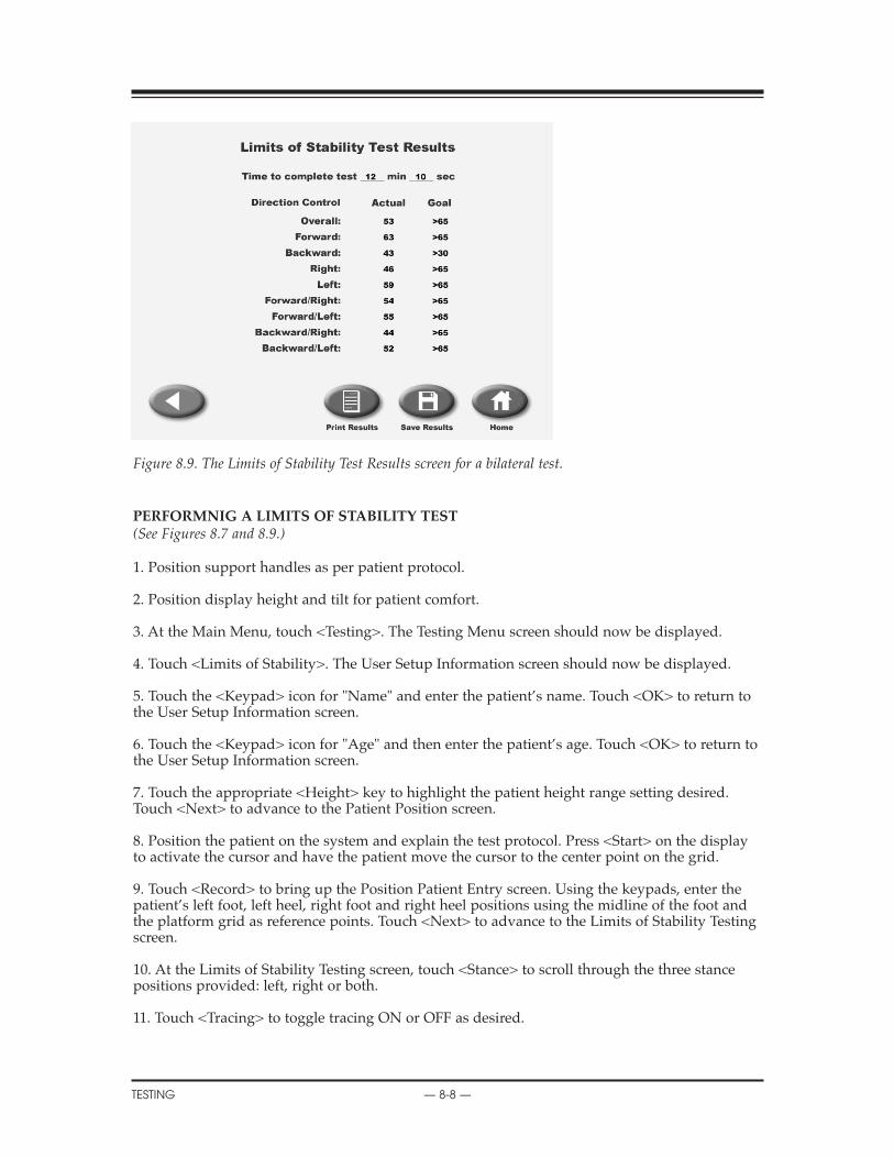
Figure 8.9. The Limits of Stability Test Results screen for a bilateral test.
PERFORMNIG A LIMITS OF STABILITY TEST(See Figures 8.7 and 8.9.)
1. Position support handles as per patient protocol.
2. Position display height and tilt for patient comfort.
3. At the Main Menu, touch <Testing>. The Testing Menu screen should now be displayed.
4. Touch <Limits of Stability>. The User Setup Information screen should now be displayed.
5. Touch the <Keypad> icon for "Name" and enter the patient’s name. Touch <OK> to return tothe User Setup Information screen.
6. Touch the <Keypad> icon for "Age" and then enter the patient’s age. Touch <OK> to return tothe User Setup Information screen.
7. Touch the appropriate <Height> key to highlight the patient height range setting desired.Touch <Next> to advance to the Patient Position screen.
8. Position the patient on the system and explain the test protocol. Press <Start> on the displayto activate the cursor and have the patient move the cursor to the center point on the grid.
9. Touch <Record> to bring up the Position Patient Entry screen. Using the keypads, enter thepatient’s left foot, left heel, right foot and right heel positions using the midline of the foot andthe platform grid as reference points. Touch <Next> to advance to the Limits of Stability Testingscreen.
10. At the Limits of Stability Testing screen, touch <Stance> to scroll through the three stancepositions provided: left, right or both.
11. Touch <Tracing> to toggle tracing ON or OFF as desired.
CONTENTS
TESTING — 8-8 —

12. Touch <Clear Tracing> to clear any tracing that remains from previous tests.
13. Touch <More Options> to advance to the Limits of Stability Test Options screen if desired.Here you can set the number of trials, rest countdown, platform stability and limits of stabilityhold time. You can also toggle the cursor ON/OFF. Touch <OK> to confirm your selections andreturn to the Limits of Stability Testing screen.
• Use the <�> or <�> keys to set the Limits of Stability Hold Time.
• To turn the cursor ON/OFF, touch <Cursor> to toggle between choices.
• To set number of trials, rest countdown or platform stability (static, 12 is most stable, 1 is leaststable,) touch the appropriate key and then enter the setting from the keypad displayed.
14. Press <Start> to release the platform (if not static) and activate the Limits of Stability Testscreen.
15. With the patient ready to begin the test, touch <Collect Data>. The screen will provide athree-second countdown before beginning the first of three test trials. The display screen willshow Test Trial Time, Platform Setting and Stance to the left of the grid. Trial Number and scoreare displayed to the right of the grid.
NOTE: To stop a test in progress at any time and return to the Limits of Stability Testing screen with theplatform locked, touch <Cancel> or <Stop>.
16. When the first trial is finished, the screen will display "Trial 1 Complete," the platform willreturn to the locked position, and a 10-second rest countdown will begin for the second trial.Touch <Collect Data> to begin the second test trial and continue in the same manner to com-plete trials two and three.
17. After completing the test, a "Test Complete" message is displayed. Touch <Results> toadvance to the Limits of Stability Test Results screen.
18. At the Limits of Stability Test Results screen, touch <Print> to automatically generate a print-ed report if desired. If you have performed a Bilateral Test, the Test Results screen and reportwill provide a bilateral comparison.
19. To save the test data, touch <Save Results> and then touch <OK> in response to the "SaveResults for later reporting or export?" prompt. The system will display "Save Results Completedafter the results are saved.
20. To return to the Opening Menu from the Limits of Stability Test Results screen touch <Home>.
CONTENTS
— 8-9 — TESTING
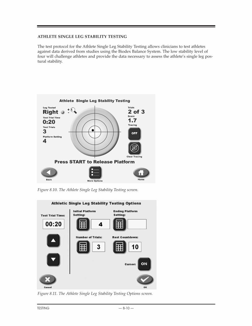
ATHLETE SINGLE LEG STABILITY TESTING
The test protocol for the Athlete Single Leg Stability Testing allows clinicians to test athletesagainst data derived from studies using the Biodex Balance System. The low stability level offour will challenge athletes and provide the data necessary to assess the athlete’s single leg pos-tural stability.
Figure 8.10. The Athlete Single Leg Stability Testing screen.
Figure 8.11. The Athlete Single Leg Stability Testing Options screen.
CONTENTS
TESTING — 8-10 —
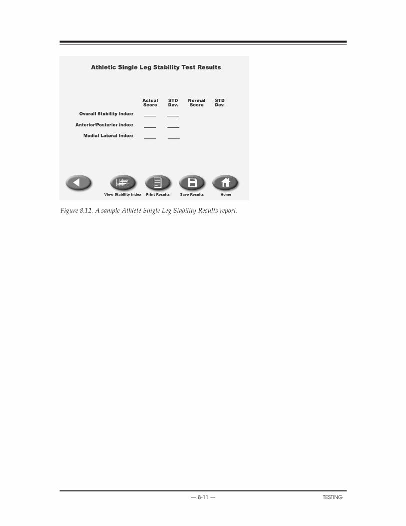
Figure 8.12. A sample Athlete Single Leg Stability Results report.
CONTENTS
— 8-11 — TESTING
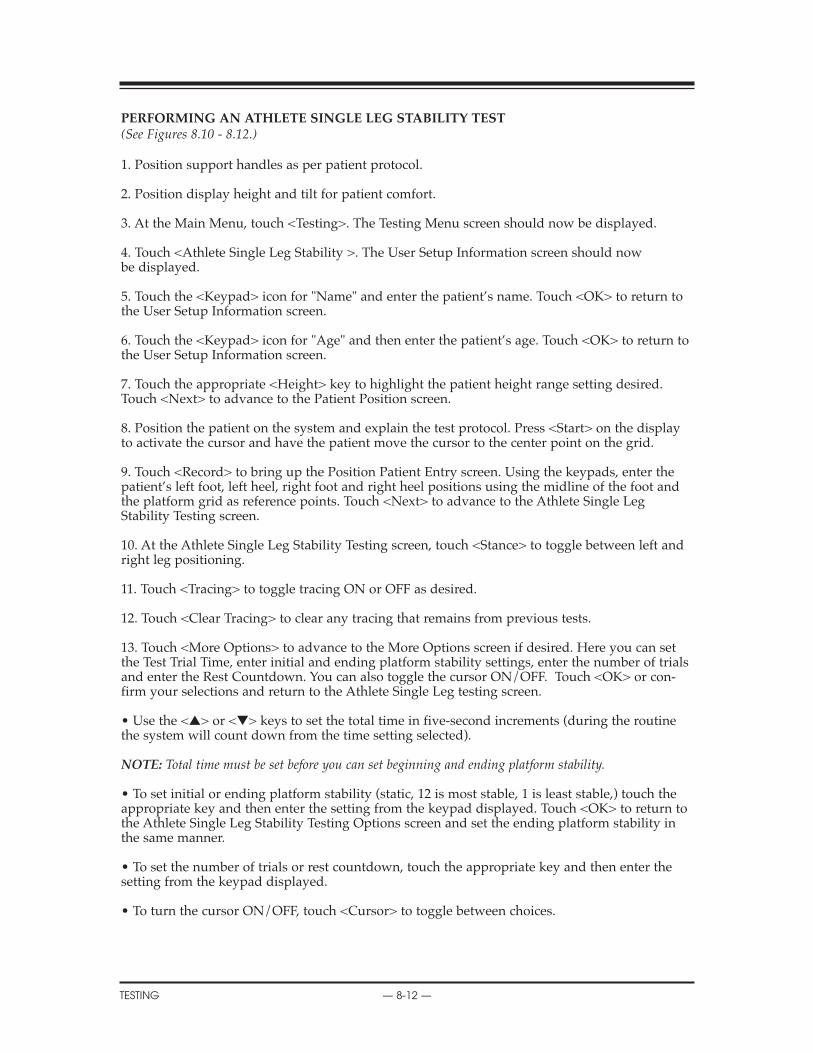
PERFORMING AN ATHLETE SINGLE LEG STABILITY TEST(See Figures 8.10 - 8.12.)
1. Position support handles as per patient protocol.
2. Position display height and tilt for patient comfort.
3. At the Main Menu, touch <Testing>. The Testing Menu screen should now be displayed.
4. Touch <Athlete Single Leg Stability >. The User Setup Information screen should nowbe displayed.
5. Touch the <Keypad> icon for "Name" and enter the patient’s name. Touch <OK> to return tothe User Setup Information screen.
6. Touch the <Keypad> icon for "Age" and then enter the patient’s age. Touch <OK> to return tothe User Setup Information screen.
7. Touch the appropriate <Height> key to highlight the patient height range setting desired.Touch <Next> to advance to the Patient Position screen.
8. Position the patient on the system and explain the test protocol. Press <Start> on the displayto activate the cursor and have the patient move the cursor to the center point on the grid.
9. Touch <Record> to bring up the Position Patient Entry screen. Using the keypads, enter thepatient’s left foot, left heel, right foot and right heel positions using the midline of the foot andthe platform grid as reference points. Touch <Next> to advance to the Athlete Single LegStability Testing screen.
10. At the Athlete Single Leg Stability Testing screen, touch <Stance> to toggle between left andright leg positioning.
11. Touch <Tracing> to toggle tracing ON or OFF as desired.
12. Touch <Clear Tracing> to clear any tracing that remains from previous tests.
13. Touch <More Options> to advance to the More Options screen if desired. Here you can setthe Test Trial Time, enter initial and ending platform stability settings, enter the number of trialsand enter the Rest Countdown. You can also toggle the cursor ON/OFF. Touch <OK> or con-firm your selections and return to the Athlete Single Leg testing screen.
• Use the <�> or <�> keys to set the total time in five-second increments (during the routinethe system will count down from the time setting selected).
NOTE: Total time must be set before you can set beginning and ending platform stability.
• To set initial or ending platform stability (static, 12 is most stable, 1 is least stable,) touch theappropriate key and then enter the setting from the keypad displayed. Touch <OK> to return tothe Athlete Single Leg Stability Testing Options screen and set the ending platform stability inthe same manner.
• To set the number of trials or rest countdown, touch the appropriate key and then enter thesetting from the keypad displayed.
• To turn the cursor ON/OFF, touch <Cursor> to toggle between choices.
CONTENTS
TESTING — 8-12 —
14. Press <Start> to release the platform (if not static) and activate the Limits of Stability Testscreen.
15. With the patient ready to begin the test, touch <Collect Data>. The screen will provide athree-second countdown before beginning the first of three test trials. The display screen willshow Test Trial Time, Platform Setting and Stance to the left of the grid. Trial Number and scoreare displayed to the right of the grid.
NOTE: To stop a test in progress at any time and return to the Athlete Single Leg Stability Testing screenwith the platform locked, touch <Cancel> or <Stop>.
16. When the first trial is finished, the screen will display "Trial 1 Complete," the platform willreturn to the locked position, and a 10-second rest countdown will begin for the second trial.Touch <Collect Data> to begin the second test trial and continue in the same manner to com-plete trials two and three.
17. After completing the test, a "Test Complete" message is displayed. Touch <Results> toadvance to the Athlete Single Leg Stability Test Results screen.
18. At the Athlete Single Leg Stability Test Results screen, touch <Print> to automatically gener-ate a printed report if desired.
19. To save the test data, touch <Save Results> and then touch <OK> in response to the "SaveResults for later reporting or export?" prompt. The system will display "Save Results Completedafter the results are saved.
20. To return to the Opening Menu from the Athlete Single Leg Stability Test Results screentouch <Home>.
TEST PROTOCOL FOR ATHLETE SINGLE LEG STABILITY TESTING
This test protocol can be used to compare patients of similar age ranges in a normative database.
Test Duration: 20 secondsLevel: FourStance Type: Single legTrials: 3
References:Athlete Single Leg Stability Test results compliation of data from:•Paterno MV et al, Neuromuscular Training Improves Single Limb Stability in Young FemaleAthletes. J Orthopedic Sports Therapy, June 2004•Arnold BL, Schmitz R, Examination of Balance Measures Produced by the Biodex StabilitySystem. J of Athletic Training 1998:33(4):323-327.•Rozzi S et al, Knee Joint Laxity and Neuromuscular Characteristics of Male and Female Soccerand Basketball Players. American J Sports Medicine, Vol. 27, No 3, 1999.
CONTENTS
— 8-13 — TESTING
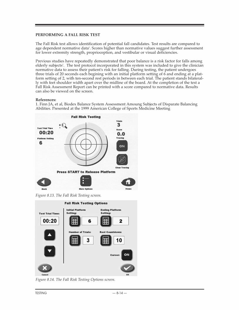
PERFORMING A FALL RISK TEST
The Fall Risk test allows identification of potential fall candidates. Test results are compared toage dependent normative data1. Scores higher than normative values suggest further assessmentfor lower extremity strength, proprioception, and vestibular or visual deficiencies.
Previous studies have repeatedly demonstrated that poor balance is a risk factor for falls amongelderly subjects1. The test protocol incorporated in this system was included to give the cliniciannormative data to assess their patient's risk for falling. During testing, the patient undergoesthree trials of 20 seconds each begining with an initial platform setting of 6 and ending at a plat-form setting of 2, with ten-second rest periods in between each trial. The patient stands bilateral-ly with feet shoulder width apart over the midline of the board. At the completion of the test aFall Risk Assessment Report can be printed with a score compared to normative data. Resultscan also be viewed on the screen.
References:1. Finn JA, et al, Biodex Balance System Assessment Amoung Subjects of Disparate BalancingAbilities. Presented at the 1999 American College of Sports Medicine Meeting
Figure 8.13. The Fall Risk Testing screen.
Figure 8.14. The Fall Risk Testing Options screen.
CONTENTS
TESTING — 8-14 —
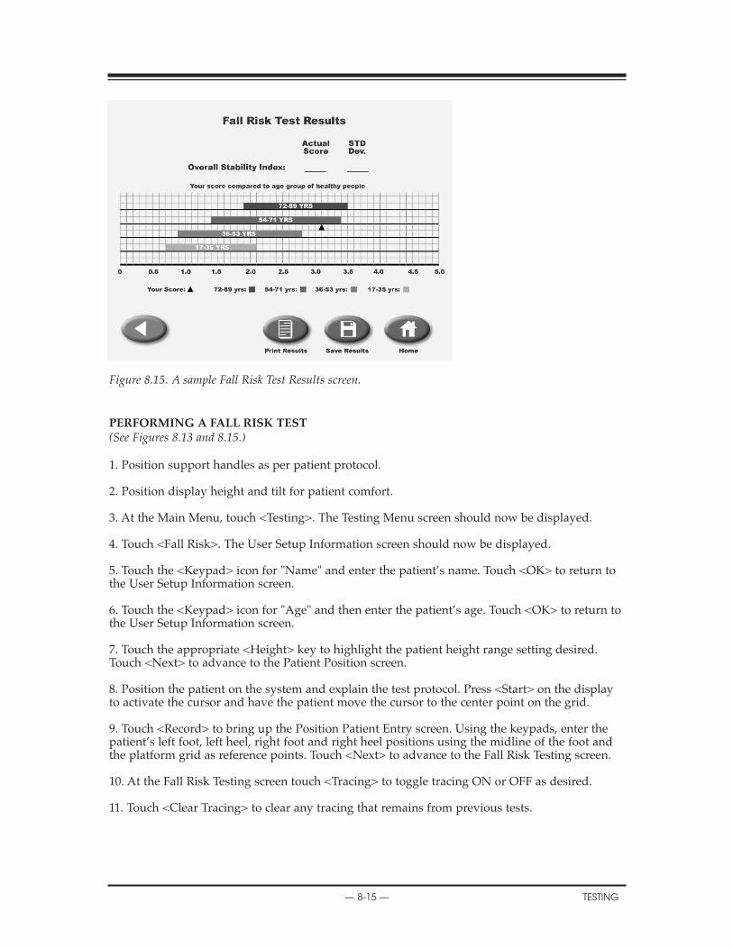
Figure 8.15. A sample Fall Risk Test Results screen.
PERFORMING A FALL RISK TEST(See Figures 8.13 and 8.15.)
1. Position support handles as per patient protocol.
2. Position display height and tilt for patient comfort.
3. At the Main Menu, touch <Testing>. The Testing Menu screen should now be displayed.
4. Touch <Fall Risk>. The User Setup Information screen should now be displayed.
5. Touch the <Keypad> icon for "Name" and enter the patient’s name. Touch <OK> to return tothe User Setup Information screen.
6. Touch the <Keypad> icon for "Age" and then enter the patient’s age. Touch <OK> to return tothe User Setup Information screen.
7. Touch the appropriate <Height> key to highlight the patient height range setting desired.Touch <Next> to advance to the Patient Position screen.
8. Position the patient on the system and explain the test protocol. Press <Start> on the displayto activate the cursor and have the patient move the cursor to the center point on the grid.
9. Touch <Record> to bring up the Position Patient Entry screen. Using the keypads, enter thepatient’s left foot, left heel, right foot and right heel positions using the midline of the foot andthe platform grid as reference points. Touch <Next> to advance to the Fall Risk Testing screen.
10. At the Fall Risk Testing screen touch <Tracing> to toggle tracing ON or OFF as desired.
11. Touch <Clear Tracing> to clear any tracing that remains from previous tests.
CONTENTS
— 8-15 — TESTING

12. Touch <More Options> to advance to the Fall Risk Test Options screen if desired. Here youcan set the Test Trial Time, enter the number of trials and enter the Rest Countdown. You canalso toggle the cursor ON/OFF. Touch <OK> to confirm your selections and return to the FallRisk Testing screen.
• Use the <�> or <�> keys to set the Test Trial time in five-second increments (during the rou-tine the system will count down from the time setting selected).
• To turn the cursor ON/OFF, touch <Cursor> to toggle between choices.
• To set the number of trials or rest countdown, touch the appropriate key and then enter thesetting from the keypad displayed.
13. Press <Start> to release the platform (if not static) and activate the Fall Risk Test screen.
14. With the patient ready to begin the test, touch <Collect Data>. The screen will provide athree-second countdown before beginning the first test trial. The display screen will show TestTrial Time and Platform Setting to the left of the grid. Trial Number and score are displayed tothe right of the grid.
NOTE: To stop a test in progress at any time and return to the Fall Risk Testing screen with the platformlocked, touch <Cancel> or <Stop>.
15. When the first trial is finished, the screen will display "Trial 1 Complete," the platform willreturn to the locked position, and the rest countdown will begin for the second trial. Touch<Collect Data> to begin the second test trial and continue in the same manner to complete trialstwo and three.
16. After completing the test, a "Test Complete" message is displayed. Touch <Results> toadvance to the Fall Risk Test Results screen.
17. At the Fall Risk Test Results screen, touch <Print> to automatically generate a printed reportif desired.
18. To save the test data, touch <Save Results> and then touch <OK> in response to the "SaveResults for later reporting or export?" prompt. The system will display "Save ResultsCompleted" after the results are saved.
19. To return to the Opening Menu from the Fall Risk Test Results screen touch <Home>.
10. DATA INTERPRETATION
TESTING — 8-16 —
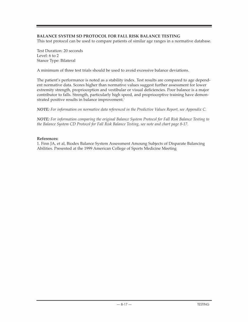
BALANCE SYSTEM SD PROTOCOL FOR FALL RISK BALANCE TESTINGThis test protocol can be used to compare patients of similar age ranges in a normative database.
Test Duration: 20 secondsLevel: 6 to 2Stance Type: Bilateral
A minimum of three test trials should be used to avoid excessive balance deviations.
The patient’s performance is noted as a stability index. Test results are compared to age depend-ent normative data. Scores higher than normative values suggest further assessment for lowerextremity strength, proprioception and vestibular or visual deficiencies. Poor balance is a majorcontributor to falls. Strength, particularly high speed, and proprioceptive training have demon-strated positive results in balance improvement.1
NOTE: For information on normative data referenced in the Predictive Values Report, see Appendix C.
NOTE: For information comparing the original Balance System Protocol for Fall Risk Balance Testing tothe Balance System CD Protocol for Fall Risk Balance Testing, see note and chart page 8-17.
References:1. Finn JA, et al, Biodex Balance System Assessment Amoung Subjects of Disparate BalancingAbilities. Presented at the 1999 American College of Sports Medicine Meeting
CONTENTS
— 8-17 — TESTING
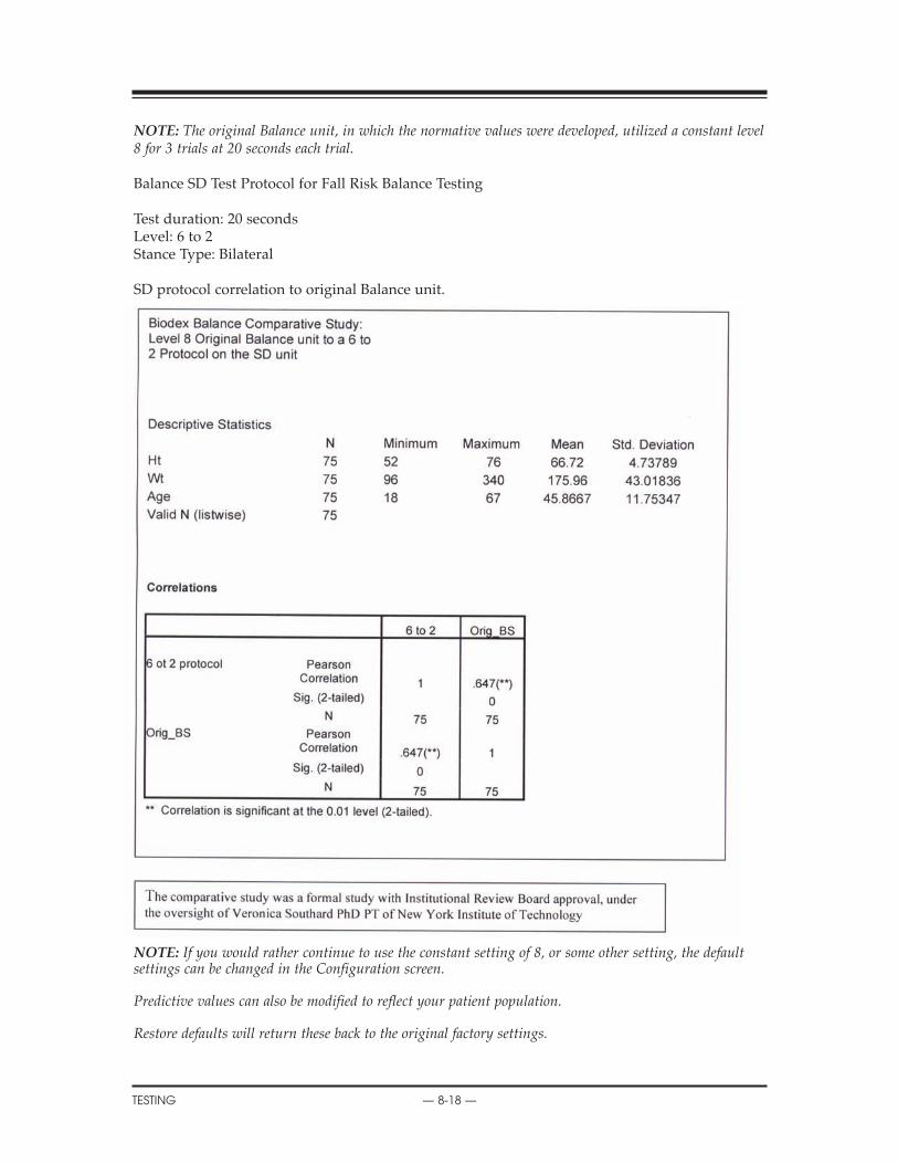
NOTE: The original Balance unit, in which the normative values were developed, utilized a constant level8 for 3 trials at 20 seconds each trial.
Balance SD Test Protocol for Fall Risk Balance Testing
Test duration: 20 secondsLevel: 6 to 2Stance Type: Bilateral
SD protocol correlation to original Balance unit.
NOTE: If you would rather continue to use the constant setting of 8, or some other setting, the defaultsettings can be changed in the Configuration screen.
Predictive values can also be modified to reflect your patient population.
Restore defaults will return these back to the original factory settings.
CONTENTS
TESTING — 8-18 —
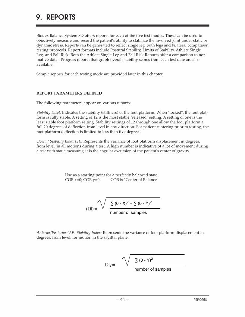
Biodex Balance System SD offers reports for each of the five test modes. These can be used toobjectively measure and record the patient’s ability to stabilize the involved joint under static ordynamic stress. Reports can be generated to reflect single leg, both legs and bilateral comparisontesting protocols. Report formats include Postural Stability, Limits of Stability, Athlete SingleLeg, and Fall Risk. Both the Athlete Single Leg and Fall Risk Reports offer a comparison to nor-mative data1. Progress reports that graph overall stability scores from each test date are alsoavailable.
Sample reports for each testing mode are provided later in this chapter.
REPORT PARAMETERS DEFINED
The following parameters appear on various reports:
Stability Level: Indicates the stability (stiffness) of the foot platform. When "locked", the foot plat-form is fully stable. A setting of 12 is the most stable "released" setting. A setting of one is theleast stable foot platform setting. Stability settings of 12 through one allow the foot platform afull 20 degrees of deflection from level in any direction. For patient centering prior to testing, thefoot platform deflection is limited to less than five degrees.
Overall Stability Index (SI): Represents the variance of foot platform displacement in degrees,from level, in all motions during a test. A high number is indicative of a lot of movement duringa test with static measures; it is the angular excursion of the patient's center of gravity.
Use as a starting point for a perfectly balanced state.COB x=0; COB y=0 COB is "Center of Balance"
Anterior/Posterior (AP) Stability Index: Represents the variance of foot platform displacement indegrees, from level, for motion in the sagittal plane.
9. REPORTS
— 9-1 — REPORTS
∑ (0 - X)2 + ∑ (0 - Y)2
number of samplesOverall Stability Index =
∑ (0 - Y)2
number of samplesAnterior/Posterior Stability Index =
(Dl) =
Dly =
Xn2 + Yn2 (p

Medial/Lateral (M/L) Stability Index: Represents the variance of foot platform displacement indegrees, from level, for motion in the frontal plane.
Mean Deflection: Average position for the patient in all motions throughout the test.
A/P Mean Deflection: Average position of side-to-side motion for the patient throughout the test.
M/L Mean Deflection: Average position for the patient in the frontal plane throughout the test.
Standard Deviation: The amount of variability in the statistical measure. A low standard deviationdemonstrates that the range of values from which the mean was calculated were close together.
NOTE: Mean, A/P and M/L Deflections are from the patient’s actual position in contrast to the StabilityIndex, which is a variance from level as established during the centering patient portion of the test proto-col. The resulting scores for Mean, A/P and M/L Deflections are not statistically effected by the centeringprocess.
12. SYSTEM UTILITIES
REPORTS — 9-2 —
∑ (0 - X)2
number of samplesMedical/Lateral Stability Index =Dlx =
∑ (Xn, Yn)Mean Deflection = nn
∑ Yn
nA/P Mean Deflection = nn = # of samplesYn = n th sample
∑ Xn
nM/L Mean Deflection = nn = # of samplesXn = n th sample
Xn2 + Yn2(Xn, Yn) = (position vector magnitude)
∑
∑ (Xn - X)2
nStandard Deviation = nn = # of samplesXn = n th sampleX = mean deflection
n

Percent Time In Zone/Quadrant: These values represent the percentage of test time the patientspends in each Zone/Quadrant during the test.
The Target Zones, A, B, C, and D, are equal to specific ranges of deflection and radiate in con-centric circles from the center of the foot platform as follows:
• Zone A = zero to five degrees foot platform deflection from level• Zone B = six to ten degrees foot platform deflection from level• Zone C = 11 - 15 degrees foot platform deflection from level• Zone D = 16 - 20 degrees foot platform deflection from level
Quadrants represent the four quarters of the Test Grid in the X and Y axis as follows:
For the "Both Feet" protocol:• Quadrant 1 = right anterior• Quadrant 2 = left anterior
Quadrants represent the four quarters of the Test Grid in the X and Y axis as follows:
For the "Both Feet" protocol:• Quadrant 3 = left posterior• Quadrant 4 = right posterior
For the "Single Foot" protocol:• Quadrant 1 = lateral anterior• Quadrant 2 = medial anterior• Quadrant 3 = medial posterior• Quadrant 4 = lateral posterior
Test Grid: Provides a visual representation of Time Spent in Zone/Quadrant. View is orientatedas if patient were looking down at foot platform while facing the display module.
Anterior/Posterior and Medial/Lateral Deflection Graphs: Provides a visual representation of A/Pand M/L deflection during the test. View is oriented as if foot platform were positioned at eyelevel on a horizontal plane. X axis = time and stability level.
CONTENTS
— 9-3 — REPORTS
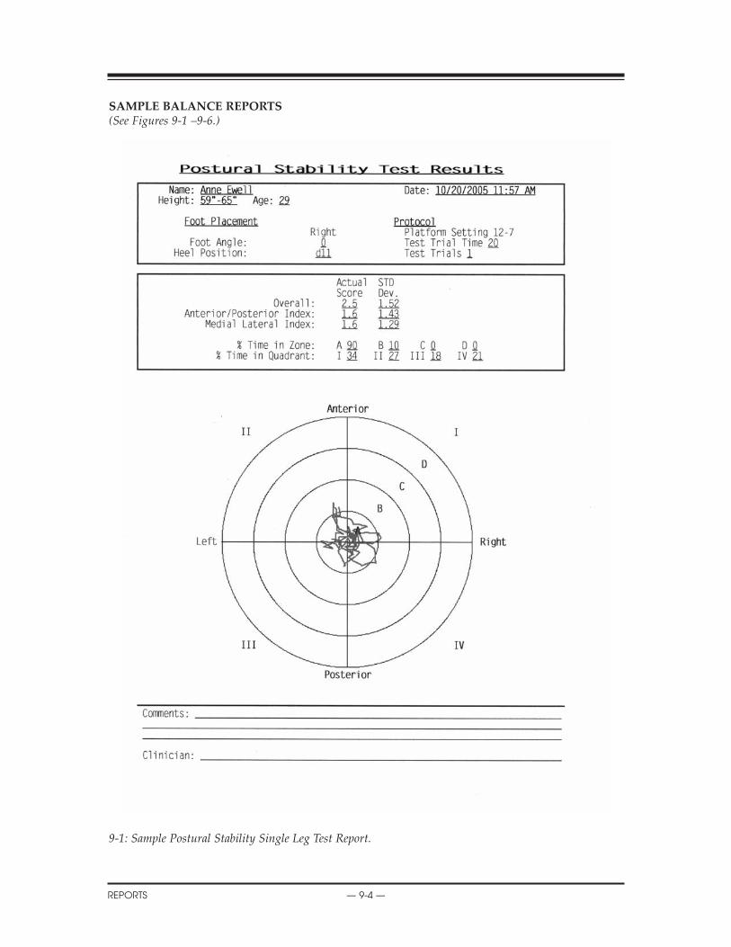
SAMPLE BALANCE REPORTS(See Figures 9-1 –9-6.)
9-1: Sample Postural Stability Single Leg Test Report.
CONTENTS
REPORTS — 9-4 —
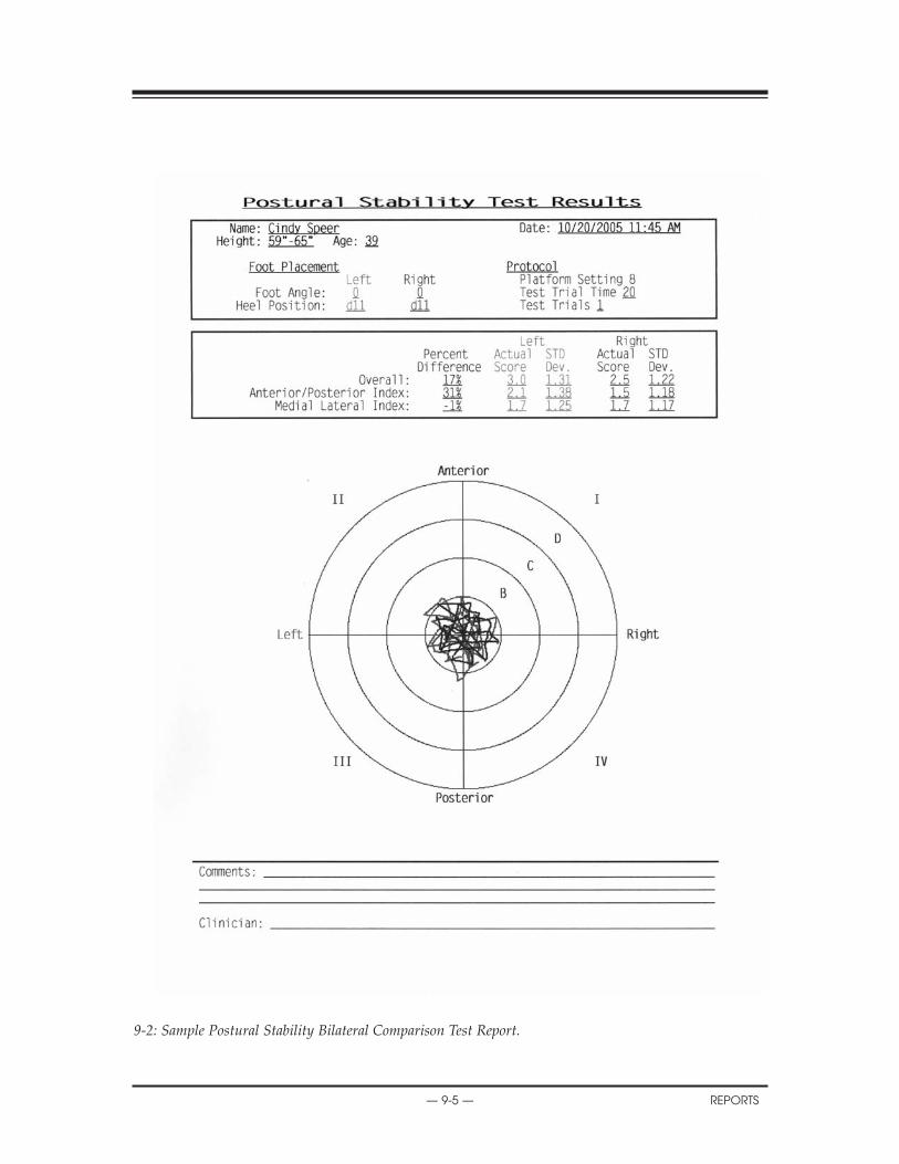
9-2: Sample Postural Stability Bilateral Comparison Test Report.
13. BIODEX BALANCE SYSTEM REIMBURSEMENT
— 9-5 — REPORTS

9-3: Limits of Stability Single Leg Test Report (unilateral stance).
14. GENERAL MAINTENANCE
REPORTS — 9-6 —
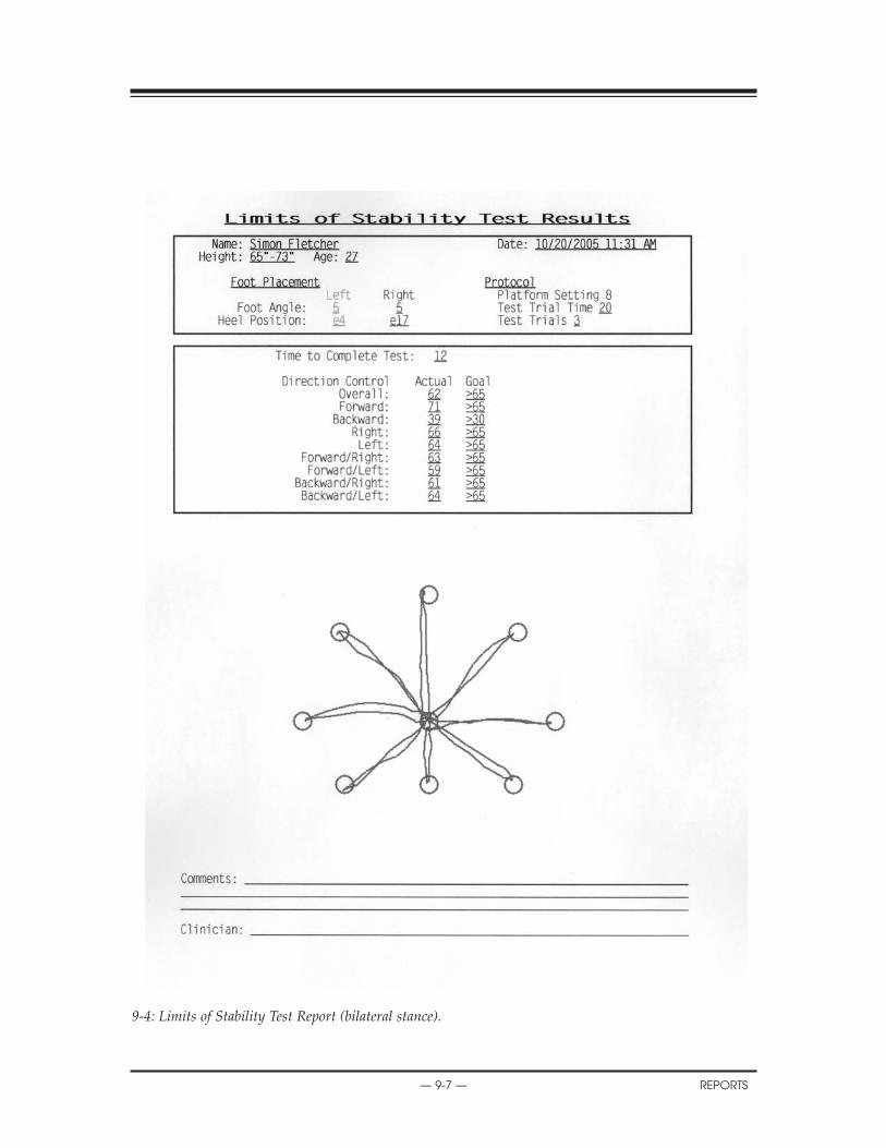
9-4: Limits of Stability Test Report (bilateral stance).
15. SERVICE PROCEDURES
— 9-7 — REPORTS
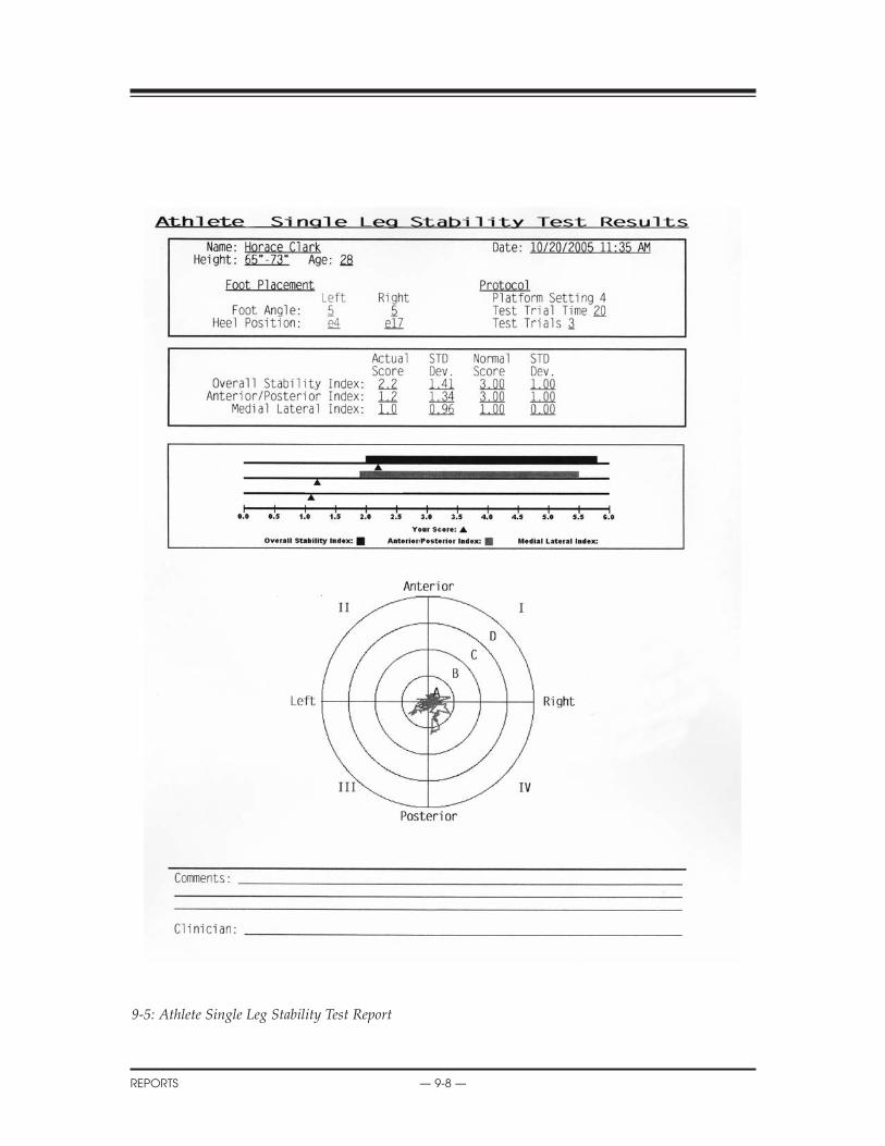
9-5: Athlete Single Leg Stability Test Report
CONTENTS
REPORTS — 9-8 —

9-6: Fall Risk Test Report.
CONTENTS
— 9-9 — REPORTS
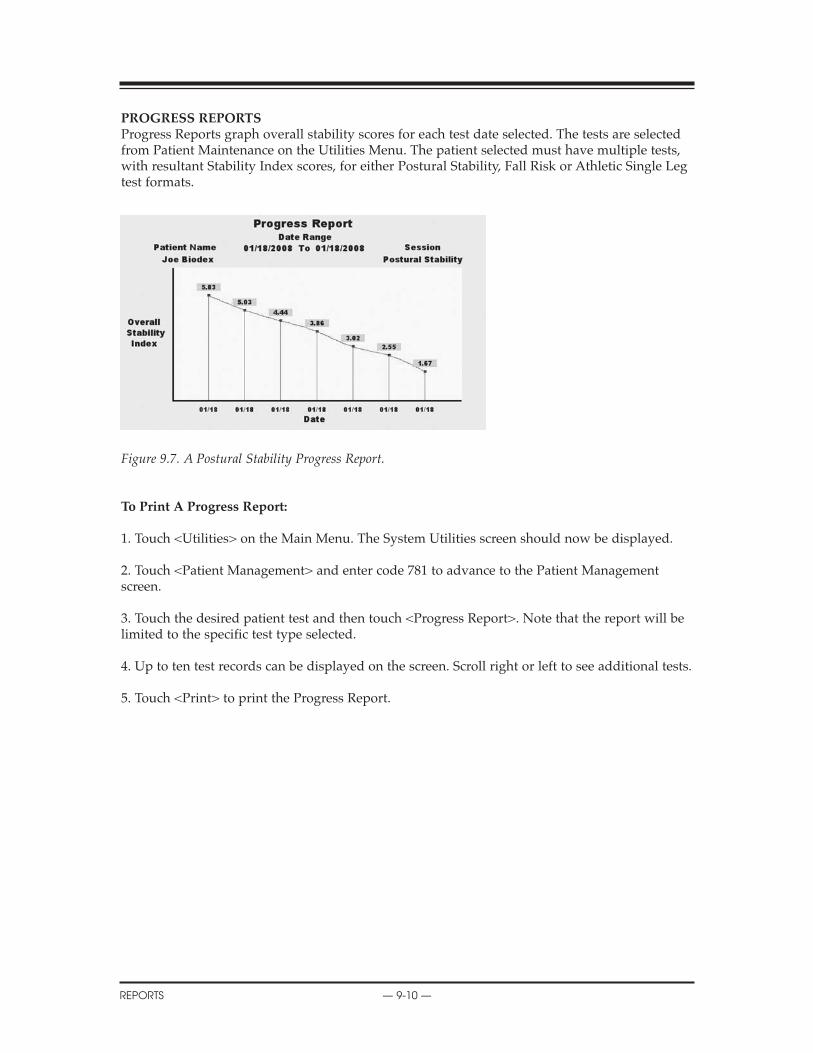
PROGRESS REPORTSProgress Reports graph overall stability scores for each test date selected. The tests are selectedfrom Patient Maintenance on the Utilities Menu. The patient selected must have multiple tests,with resultant Stability Index scores, for either Postural Stability, Fall Risk or Athletic Single Legtest formats.
Figure 9.7. A Postural Stability Progress Report.
To Print A Progress Report:
1. Touch <Utilities> on the Main Menu. The System Utilities screen should now be displayed.
2. Touch <Patient Management> and enter code 781 to advance to the Patient Managementscreen.
3. Touch the desired patient test and then touch <Progress Report>. Note that the report will belimited to the specific test type selected.
4. Up to ten test records can be displayed on the screen. Scroll right or left to see additional tests.
5. Touch <Print> to print the Progress Report.
CONTENTS
REPORTS — 9-10 —
ASSESSING LIMITS OF STABILITY WITH THE BIODEX BALANCE SYSTEM
The Limits of Stability (LOS) for standing balance has been defined as the maximum angle abody can achieve from vertical without losing one’s balance. Once the LOS is exceeded a fall,stumble or step will ensue. LOS in normal adults is eight degrees anterior, four degrees posteri-or, and 16 degrees in the lateral direction.
In the static mode the patient’s movements are calculated as the average amount of angular dis-placement of the Center of Gravity (COG). This is then further defined as a percentage of thepatients’s Limits of Stability.
At 100% of the LOS, a patient will fall if they don’t respond appropriately.
Center is established in the test protocol during the centering process where patients must posi-tion themselves so the platform is flat and the cursor is centered. In actuality, this process is toposition the COG over the point of the vertical ground reaction force.
An Anterior/Posterior Stability Index of 6.8 means the average displacement from center is 6.8degrees. LOS for A/P motion is 12 degrees. In this case, the patient was able to control their bal-ance to remain within 57% of their A/P LOS.
Balance is a complex process involving visual, vestibular and neuromuscular control. TheBiodex Balance System will prove to be a more sensitive test of balance performance becausebeing a dynamic tilting platform it will invoke the neuromuscular control aspects more so than astatic force plate type system, as well as the visual and vestibular components.
The Biodex Balance System will provide an accurate, reliable assessment of a patient’s balanceperformance. This objective measure can be correlated to actual functional activity performance,fall incidence and fall direction. In addition, balance mobility programs can be evaluatedthrough objective assessment of the effects of lower extremity exercise on balance performance.
INTERPRETING PATIENT PERFORMANCE
The patient’s performance is noted in the following ways:
1. Stability Index:The stability index represents the variance of platform displacement in degrees from level. Ahigh number is indicative of a lot of motion which is indicative of the patients having troublebalancing. Differences between right and left limbs can be noted.
2. Percent Time in Zone Quadrant:Example: If a patient with a right lateral ankle sprain spends the vast majority of time in Zone 1,the trend will be to fall into inversion. This gives feedback as to the exact ankle position beingchallenged.
3. Test Grid:For testing, as the patient goes further and further from the center of axis, the patient is beingchallenged to sustain proper position. For rehabilitation, we can note how far the patient candeviate from the center and still maintain a proper position.
10. DATA
— 10-1 — DATA
BALANCE SYSTEM STATISTIC DEFINITIONS
Stability Index: Represents the variance of platform displacement in degrees from level. A highnumber is indicative of the patient having trouble balancing. The patient's Actual Stability Indexis represented in the Predictive Values Report (see Figure 22) under the column labeled "ActualValues." The Actual Value can be compared to age related Predictive Value, this is found to theimmediate left of the Actual Value under the column labeled "Predictive Values." Should yourpatient's Actual Values not fit into the range of the Predictive Values there is a balance problem.Bilateral comparisons can be made to determine progress made during rehabilitation on theComparative Report (see Figure 9-2).
Anterior/Posterior Stability Index: Represents the variance of platform displacement in degreesfrom level for motion in the sagittal plane.
Medial/Lateral Stability Index: Represents the variance of platform displacement in degrees fromlevel for motion in the frontal plane.
Standard Deviation: The amount of variability in the statistical measure. A low standard deviationdemonstrates that the range of values from which the mean was calculated were close together.
CONTENTS
DATA — 10-2 —

The System Utilities allow users to access the System Configuration and Patient Managementscreens.
To access the System Utilities, touch <Utilities> on the Main Menu. The System Utilities screenshould now be displayed. From here you can select Configuration or Patient Management bytouching the desired icon.
CONFIGURATION(See Figure 11.1 and 11.2.)
At the System Utilities screen, touch <Configuration> and then enter 781 in response to the"Enter Access Code" prompt. Touch <OK>. The Configuration screen should now be displayed.At this screen users can set values for Screen Time Out, Date/Time and Default Settings. Youcan also turn Tone ON/OFF, adjust LCD brightness or Tone volume, and select MeasurementUnits, Printer Resolution or Joystick Emulation. When you have finished making all of yourselections and adjustments, touch <OK> to return to the Main Menu.
Set Screen Time OutThe Screen Time Out setting determines how long the display screen remains ON when the sys-tem is not in use of the test/exercise is completed. Once the selected time expires, the screenfades to black even if the system remains ON.
1. At the Configuration Screen, touch <Set Screen Time Out>. The Set Test/Exercise CompleteScreen Time Out screen should now be displayed.
2. Use the <�> or <�> arrows to increase or decrease the value displayed in 30-secondincrements. Time Out range is from 00:00 to 30:00.
3. Touch <OK> to confirm your changes and return to the Configuration screen. Touch <Cancel>to return to the Configuration screen without making any changes.
Set Date/TimeTime and Date are system-wide parameters that show on all printed reports.
1. At the Configuration Screen, touch <Set Date/Time>. The Set System Date/Time screenshould now be displayed.
2. Touch the parameter to set so that the selected field is highlighted.
3. Use the <�> or <�> arrows to increase or decrease the value displayed for the highlightedparameter.
4. Repeat steps 2 and 3 until you have adjusted all the parameters you wish to correct.
5. Touch <OK> to confirm your changes and return to the Configuration screen. Touch <Cancel>to return to the Configuration screen without making any changes.
11. SYSTEM UTILITIES
— 11-1 — SYSTEM UTILITIES

Turn Tone ON/OFFThis setting enables or disables an audible tone which signals test or exercise start, completionand countdown between trials.
1. At the Configuration screen, simply touch the ON or OFF icon to select the desired setting.
Adjust LCD BrightnessThis setting brightens or darkens the display screen for all applications.
1. At the Configuration screen, simply touch along the LCD Brightness Bar Scale until thedesired display brightness is achieved. The left end of the scale is darkest, the right end of thescale is lightest.
Adjust Tone VolumeThis setting raises or lowers the volume of the audible tone which signals test or exercise start,completion and countdown between trials.
1. At the Configuration screen, simply touch along the Tone Volume Bar Scale until the desiredlevel is achieved. The left end of the scale is least loud, the right end of the scale is most loud.
Select Measure Units, Printer Resolution or Joystick EmulationAll three of these setting are simple toggle choices. Simply touch the desired parameter to viewthe choices, then touch the setting you want to select.
•Measurer Units: Metric or US•Printer Resolution: normal or high•Joystick Emulation: disabled or enabled
Default SettingsAt the Default Settings screen, users can set the default Fall Risk Platform setting, adjustPredictive Values, or return these parameters to their original factory-set default values.
To adjust the Fall Risk Platform setting:
1. At the Configuration Screen, touch <Default Settings>. The Default Settings screen shouldnow be displayed.
2. Touch <Platform Setting>.
3. Enter the desired platform setting via the key pad displayed.
4. Touch <Ok> to return to the Default Settings screen.
To Adjust the Predictive Values:1. At the Configuration Screen, touch <Default Settings>. The Default Settings screen shouldnow be displayed.
2. Touch to highlight the predictive value to you wish to adjust.
3. Use the <�> or <�> arrows to increase or decrease the value displayed.
CONTENTS
SYSTEM UTILITIES — 11-2 —

Figure 11.1. The Configuration screen.
Figure 11.2. System Default Settings.
CONTENTS
— 11-3 — SYSTEM UTILITIES

PATIENT MANAGEMENT(See Figure 11.3 - 11.5.)At the System Utilities screen, touch <Patient Management > and then enter 781 in response to the"Enter Access Code" prompt. Touch <OK>. The Patient Management screen should now be dis-played. This screen shows a listing of patient and associated saved test and training sessions alongwith the date performed. Use the <�> or <�> arrows to scroll through the list of patient tests.
Figure 11.3. The Patient Management Screen.
View Test Results(See Figure 11.4.)To view the results of any test displayed simply touch the desired entry on the PatientManagement screen to produce an on-screen report.
Figure 11.4. A single, stored, patient Postural Stability Test Record.
Repeat (recall a patient for a test or exercise session)To repeat any saved test or exercise session, touch <Repeat> on the on-screen report. The systemwill return to the appropriate test or training Position Patient screen with the position values forfoot and heel reflecting the selected session. The selected name, age and height of the selectedpatient will also be recorded with the new test or training session if you save at completion.
16. TROUBLE-SHOOTING
SYSTEM UTILITIES — 11-4 —
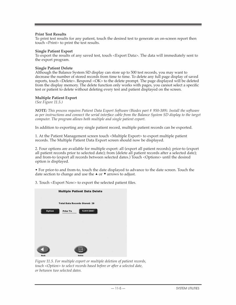
Print Test ResultsTo print test results for any patient, touch the desired test to generate an on-screen report thentouch <Print> to print the test results.
Single Patient ExportTo export the results of any saved test, touch <Export Data>. The data will immediately sent tothe export program.
Single Patient DeleteAlthough the Balance System SD display can store up to 500 test records, you may want todecrease the number of stored records from time to time. To delete any full page display of savedreports, touch <Delete>. Respond <OK> to the delete prompt. The page displayed will be deletedfrom the display memory. The delete function only works with pages, you cannot select a specifictest or patient to delete without deleting every test and patient displayed on the screen.
Multiple Patient Export(See Figure 11.5.)
NOTE: This process requires Patient Data Export Software (Biodex part # 950-389). Install the softwareas per instructions and connect the serial interface cable from the Balance System SD display to the targetcomputer. The program allows both multiple and single patient export.
In addition to exporting any single patient record, multiple patient records can be exported.
1. At the Patient Management screen touch <Multiple Export> to export multiple patientrecords. The Multiple Patient Data Export screen should now be displayed.
2. Four options are available for multiple export: all (export all patient records); prior-to (exportall patient records prior to selected date); from (delete all patient records after a selected date);and from-to (export all records between selected dates.) Touch <Options> until the desiredoption is displayed.
• For prior-to and from-to, touch the date displayed to advance to the date screen. Touch thedate section to change and use the ▲ or ▼ arrows to adjust.
3. Touch <Export Now> to export the selected patient files.
Figure 11.5. For multiple export or multiple deletion of patient records,touch <Option> to select records based before or after a selected date,or between two selected dates.
17. BIBLIOGRAPHY
— 11-5 — SYSTEM UTILITIES

Multiple Patient DeleteIn addition to deleting any single patient record, multiple patient records can be deleted.
1. At the Patient Management screen touch <Multiple Delete> to delete multiple patient records.The Multiple Patient Data Delete screen should now be displayed.
2. Three options are available for multiple delete: all (delete all patient records); prior-to (deleteall patient records prior to selected date); and from-to (delete all records between selected dates.)Touch <Options> until the desired option is displayed.
• For prior-to and from-to, touch the date displayed to advance to the date screen. Touch thedate section to change and use the ▲ or ▼ arrows to adjust.
3. Touch <Delete Now> to delete the selected patient files.
CONTENTS
SYSTEM UTILITIES — 11-6 —
Biodex Rehabilitation Equipment is commonly used in rehabilitation services based on aphysician referral for these ICD-9 codes. As a result, these CPT codes may be applied.Reimbursement amounts vary among plans and states.
Physician referral and ICD-9 codes:
V15.88 Personal History of Fall728.87 Muscle weakness729.89 Leg weakness715.0 Degenerative joint disease715.2 Secondary localized osteoarthritis781.2 Abnormal gait719.7 Difficulty in walking719.4 Joint pain719.5 Joint stiffness718.8 Instability of joint
The following CPT codes can be applied.Reimbursement amounts vary among plans and states.
97110 Therapeutic procedure, one or more areas, each 15 minutes;therapeutic exercise to develop strength, endurance, range of motion and flexibility.
97112 Neuromuscular reeducation of movement, balance, coordination, kinesthetic sense,posture, and/or proprioception for sitting and/or standing activities.
97116 Gait Training (includes stair climbing)97530 Therapeutic activities, direct (one-on-one) patient contact by the provider
(use of dynamic activities to improve functional performance), each 15 minutes97535 Self-care/home management t raining (eg, activities of daily living (ADL) and
compensatory training, meal preparation, safety procedures, and instructions in use ofassistive technology devices/adaptive equipment) direct one-on-one contact byprovider, each 15 minutes
97750 Physical performance test or measurement (eg, musculoskeletal, functional capacity)with written report, each 15 minutes
NOTE: Most insurance plans, including Medicare, cover assessment and conditioning for Fall Programs.
12. REIMBURSEMENT
— 12-1 — SYSTEM REIMBURSEMENT

The Biodex Balance System requires only the most basic general maintenance, performed on anas-needed basis at least every three to four months.
CLEANING INSTRUCTIONSWith the system turned OFF, wipe down all surfaces with a damp cloth. Mild soap and watercan be used to remove stains and scuff marks. As needed, inspect all locking and adjustmentmechanisms for signs of wear or damage.
If you have any questions or need further assistance, contact the Biodex Customer ServiceDepartment.
GENERAL MAINTENANCE PROCEDURES• Lubricate the spring assemblies with white lithium grease.• Lubricate the eight push plates with white lithium grease.• Lubricate the acme threaded rods with white lithium grease.
NOTE: When checking for lubrication, it may only be necessary to re-distribute the existing grease.
CAUTION! Some steps of these procedure require the Balance System to be turned ON. Whenthis is the case, use extreme caution working on the system.
ATTENTION: Certaines étapes de la présente marche à suivre nécessitent que le systèmed’équilibrage soit mis SOUS TENSION. En pareille circonstance, user de précautions extrêmesdans la maniplation du système.
13. GENERAL MAINTENANCE
— 13-1 — GENERAL MAINTENANCE

AKBARI, M, et al.BALANCE PROBLEMS AFTER UNILATERAL LATERALANKLE SPRAINSJ of Rehabilitation Research & Development (JRRD), Vol. 43, No. 7: 819-824, Nov/Dec 2006Biodex #91-159
ARNOLD, BL, et al.NORMAL STABILITY PATTERNS AND RELATIONSHIP AS ASSESSED WITH THE BIODEXBALANCE SYSTEMJ of Athletic Training, Vol. 32 (2):S-25 / April-June 1997Biodex #93-268
EXAMINATION OF BALANCE MEASURES PRODUCED BY THE BIODEX STABILITY SYS-TEMJ of Athletic Training, Vol. 33(4):323-27, Dec. 1998Biodex #93-287
AYDOG, E, et al.EVALUATION OF DYNAMIC POSTURAL BALANCE USING THE BIODEX STABILITY SYS-TEM IN RHEUMATOID ARTHRITIS PATIENTSAbstract only - Clin Rheumatol, 2005, Oct 25:1-6Biodex #93-104
DYNAMIC POSTURAL BALANCE IN ANKYLOSING SPONDYLITIS PATIENTSAbstract only – Rheumatology (Oxford), 2005, Nov. 8Biodex #93-105
BALLARD, TPRODUCT PROFILE: THE BIODEX BALANCE SYSTEMBiodex Medical SystemsBiodex #91-111
BEHAN, EA COMPARISON OF ADYNAMIC BALANCE SYSTEM TO A STATIC FORCE PLAST SYSTEMFOR ORTHOPEDIC AND MUSCULOSKELETAL REHABILITATIONBiodex Medical SystemsBiodex #91-113
BLACKBURN, JT, et al.BALANCE AND JOINT STABILITY:THE RELATIVE CONTRIBUTIONS OF PROPRIOCEPTION AND MUSCULAR STRENGTHJ of Athletic Training, Vol. 34(2):S-30 / April-June 1999Biodex #91-104
BLACKBURN, TA, et al.REHABILITATION AFTER LIGAMENTOUS AND LABRAL SURGERY OF THE SHOULDER:GUIDING CONCEPTSJ of Athletic Training 2000;35(3):373-381Biodex #93-111
BLACKBURN, TA, et al.SINGLE LEG STANCE: DEVELOPMENT OF RELIABLE TESTING PROCEDUREBerkshire Institute of Orthopedic & Sports Physical Therapy, Wyomissing, PABiodex #93-207
14. BIBLIOGRAPHY
— 14-1 — BIBLIOGRAPHY

APPENDIX A
BIBLIOGRAPHY — 14-2 —
CACHUPE, WJC, et al.RELIABILITY OF BIODEX BALANCE SYSTEM MEASURESHuman Performance Dept. / San Jose State University / June 2000Biodex #91-198
CAGGIANO, NA, et al.THE RELATIONSHIP BETWEEN ANKLE KINESTHESIAAND PEAK TORQUE WITHSINGLE LEG MULTIAXIAL PLATFORM STABILITYJ of Athletic Training, Vol. 34(2):S-31 / April-June 1999Biodex #91-106
CAMPBELL, MH, et al.THE CORRELATION BETWEEN ISOKINETIC STRENGTH MEASURES AND FUNCTIONALPERFORMANCE IN AN ELDERLY POPULATIONBiodex #93-293
CAVANAUGH, JT, et al.BALANCE AND POSTOPERATIVE LOWER EXTREMITY JOINT RECONSTRUCTIONOrthopaedic Phys Therapy Clinics of No America; Vol.11:1, 75-99 - March 2002Biodex #92-244
CLARK, S, et al.GENERALIZABILITY OF THE LIMITS OF STABILITY TEST IN THE EVALUATION OFDYNAMIC BALANCE AMONG OLDER ADULTSArch Phys Med Rehabil Vol 78:1078-1084, October 1997Biodex #92-269
DiCOSTANZA, K, et al.EFFECT OF ADHESIVE MEDIAL LONGITUDINALARCH SUPPORT ON POSTURAL SWAYJ of Athletic Training / Vol. 36(2) (suppl) S66, April-June 2001Biodex #92-227
DOVER, G, et al.RELIABILITY OF INVERSION AND EVERSION PEAK TORQUE MEASUREMENTS FROMTHE BIODEX SYSTEM 3 ISOKINETIC DYNAMOMETERJ of Athletic Training / Vol. 35 (2) (suppl) / S-91 / April-June 2000Biodex #91-185
FERRIS, CM, et al.A COMPARISON OF STRENGTH, PROPRIOCEPTION, LAXITY, FLEXIBILITY, AND BALANCEBETWEEN BASKETBALLAND NON-BASKETBALL COLLEGIATE FEMALE ATHLETESJ of Athletic Training / Vol. 35 No. 2 (suppl) / S38 / April-June 2000Biodex #91-189
FINN, JA, et al.STABILITY PERFORMANCE ASSESSMENT AMONG SUBJECTS OF DISPARATEBALANCING ABILITIESSouthern Connecticut State University, 501 Crescent St.,New Haven, CT 06515 Phone: 203-392-6036Biodex #93-286
FLYNN, WL, et al.CHANGES IN DYNAMIC POSTURAL STABILITY FOLLOWING CRYOTHERAPYJ of Athletic Training, Vol. 32(2):S-6 / April-June 1997Biodex #91-110

FREIDHOFF, G, et al.PILOT ASSESSMENT OF THE BIODEX STABILITY SYSTEM WITH NORMALS:TEST/RETEST AND DAY TO DAY RELIABILITYUniversity of Kentucky, Div. of P.T.,(Med. Center Annex I, Lexington, KY)Biodex #93-206
HINMAN, MRFACTOS AFFECTING RELIABILITY OF THE BIODEX BALANCE SYSTEM:A SUMMARY OF FOUR STUDIESJ of Sport Rehab, Vol. 9 (3):240-52, August 2000Biodex #91-194
HORNYIK, ML, et al.RELIABILITY OF LIMITS OF STABILITY TESTING: A COMPARISON OF TWO DYNAMICPOSTURAL STABILITY EVALUATION DEVICESJ of Athletic Training, Vol. 36(2) (suppl) S78, April-June 2001Biodex #92-229
HORODYSKI, MB, et al.MEASUREMENTS OF DYNAMIC POSTURAL STABILITY, VISUAL SCANNING, AND MEN-TAL FLEXIBILITY IN COLLEGIATE FOOTBALL PLAYERSJ of Athletic Training, Vol. 34(2):S85 / April-June 1999Biodex #91-108
JORDEN, RA, et al.THE INFLUENCE OF ANKLE ORTHOSES AND EXERCISE ON POSTURAL STABILITYJ of Athletic Training, Vol. 36(2) (suppl):S-78, April-June 2001Biodex #92-228
LEONARD, K, et al.CHANGES IN DYNAMIC POSTURAL STABILITY FOLLOWING CRYOTHERAPY TO THEANKLE AND KNEEJ of Athletic Training, Vol. 34(2):S-68 / April-June 1999Biodex #91-107
LEPHART, S, et al.LEARNING EFFECTS AND RELIABILITY OF THE BIODEX STABILITY SYSTEMSports Medicine & Neuromuscular Laboratory,Univ. of Pittsburgh / Pittsburgh, PABiodex #93-208
LINDEMANN, U, et al.IMPROVING BALANCE BY IMPROVING MOTOR SKILLSZ Gerontol Geriat 37:20-26 (2004)Biodex #93-205
MAGILL, J, et al.CHANGES IN DYNAMIC POSTURAL STABILITY WITH THE USE OF NEOPRENE SLEEVESJ of Athletic Training, Vol. 34(2), S-30 / April-June 1999Biodex #91-103
MALLEY, C, et al.THE EFFECTS OF THREE DIFFERENT ANKLE TRAINING PROGRAMS ON FUNCTIONALSTABILITY AND SINGLE-LIMB STANCEJ of Athletic Training, Vol. 34(2), S-30 / April-June 1999Biodex #91-105
APPENDIX A
— 14-3 — BIBLIOGRAPHY

MATTACOLA, CG, et al.STRENGTH, FUNCTIONAL OUTCOME, AND POSTURAL STABILITY CRUCITATE LIGA-MENT RECONSTRUCTIONJ of Athletic Training, Vol. 37(3): 262-268 / July-Sept 2002Biodex #92-241
MYER, GD, et al.REHABILITATION AFTER ANTERIOR CRUCIATE LIGAMENT RECONSTRUCTION: CRITE-RIA-BASED PROGRESSION THROUGH THE RETURN-T0-SPORT PHASEJ of Orthop & Sports Phy Ther, 36;6:385-402, June 2006Biodex #93-117
NELSON, AJ, et al.USING THE BIODEX UNWEIGHING SYSTEM, BALANCE SYSTEM AND GAIT TRAINER INAN INTEGRATED REHABILITATION PROGRAMAbstract, May 2001Biodex #92-217
PATERNO, MV, et al.THE RETURN OF NEUROMUSCULAR COORDINATION AFTER ANTERIOR CRUCIATELIGAMENT RECONSTRUCTIONBiodex Medical SystemsBiodex #91-112
PATERNO, MV, et al.NEUROMUSCULAR TRAINING IMPROVES SINGLE-LIMB STABILITY IN YOUNG FEMALEATHLETESJOSPT, Vol. 34 (6):305-316, June 2004Biodex #92-245
PINTO, KK, et al.THE EFFECTS OF ANKLE TAPING AND BALANCE ACTIVITIES ON BIODEX STABILITYMEASUREMENTSJ of Athletic Training, Vol. 34(2), S-30 / April-June 1999Biodex #91-102
RIEMANN, BL, et al.COMPARISON OF THE ANKLE, KNEE, HIP, AND TRUNK CORRECTIVE ACTION SHOWNDURING SINGLE-LEG STANCE ON FIRM, FOAM, AND MULTIAXIAL SURFACESArch Phys Med Rehabil, Vol. 84: 90-95, January 2003Biodex #92-237
ROZZI, SL, et al.KNEE JOINT LAXITY AND NEUROMUSCULAR CHARACTERISTICS OF MALE ANDFEMALE SOCCER AND BASETBALL PLAYERSAmerican J Sports Med, Vol. 27(3):312-319 / May-June 1999Biodex #91-101
SCHMITZ, RJ, et al.INTERTESTER AND INTRATESTER RELIABILITY OF ADYNAMIC BALANCE PROTOCOLUSING THE BIODEX STABILITY SYSTEMJ of Sports Rehab 7:95-101, 1998Biodex #93-271
CONTENTS
BIBLIOGRAPHY — 14-4 —

SIERI, T and BERETTA, G.FALL RISKASSESSMENT IN VERYOLDMALESAND FEMALES LIVING IN NURSING HOMESDisability and Rehabilitation:2004, Vol. 26, No. 12:718-723Biodex #93-106
SIUDMAK, PG, et al.CORRELATIONS BETWEEN DYNAMIC BALANCE PERFORMANCE AND ISOKINETICFUNCTIONS OF KNEE FLEXOR/EXTENSOR MUSCLES IN THE ELDERLYBiodex #93-295
TESTERMAN, C, et al.EVALUATION OF ANKLE INSTABILITY USING THE BIODEX STABILITY SYSTEMFoot Ankle Int 1999 May, 20(5):317-21 (ISSN: 1071-1007)Biodex #91-116
UUSI-RASI, K, et al.ASSOCIATIONS OF CALCIUM INTAKE AND PHYSICALACTIVITY WITH BONE DENSITYAND SIZE IN PREMENOPAUSALAND POSTMENOPAUSALWOMEN: A PERIPHERALQUANTITATIVE COMPUTED TOMOGRAPHY STUDYJ of Bone and Mineral Research, Vol 17, No. 3, 2002: 544-552Biodex #92-281
WILKERSON, GBDYNAMIC JOINT STABILITY: MECHANICALAND NEUROMUSCULARINTER-RELATIONSHIPSBiodex Medical SystemsBiodex #91-109
WINTERS, KM, et al.DETRAINING REVERSES POSITIVE EFFECTS OF EXERCISE ON THE MUSCULOSKELETALSYSTEM IN PREMENOPAUSALWOMENJ of Bone and Mineral Research, Vol 15, No. 12, 2000: 2495-2503Biodex #92-280
REV: March 12, 2008
CONTENTS
— 14-5 — BIBLIOGRAPHY

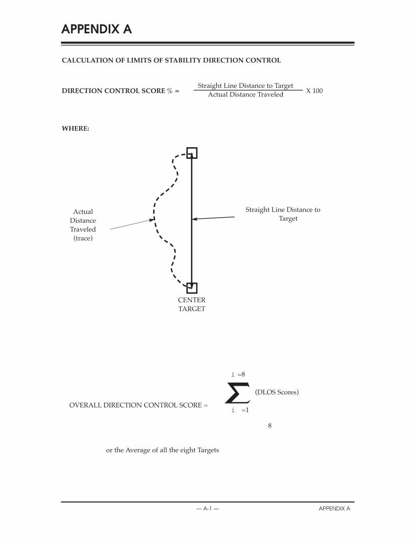
CALCULATION OF LIMITS OF STABILITY DIRECTION CONTROL
DIRECTION CONTROL SCORE % = X 100
WHERE:
— A-1 — APPENDIX A
APPENDIX A
ActualDistanceTraveled(trace)
Straight Line Distance to TargetActual Distance Traveled
Straight Line Distance toTarget
OVERALL DIRECTION CONTROL SCORE =
or the Average of all the eight Targets
(DLOS Scores)
8
i =8
i =1
CENTERTARGET
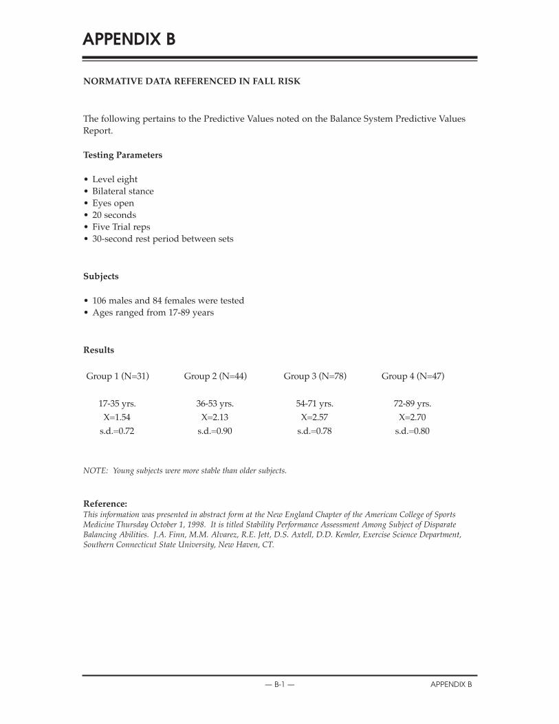
NORMATIVE DATA REFERENCED IN FALL RISK
The following pertains to the Predictive Values noted on the Balance System Predictive ValuesReport.
Testing Parameters
• Level eight• Bilateral stance• Eyes open• 20 seconds• Five Trial reps• 30-second rest period between sets
Subjects
• 106 males and 84 females were tested• Ages ranged from 17-89 years
Results
Group 1 (N=31) Group 2 (N=44) Group 3 (N=78) Group 4 (N=47)
17-35 yrs. 36-53 yrs. 54-71 yrs. 72-89 yrs.X=1.54 X=2.13 X=2.57 X=2.70s.d.=0.72 s.d.=0.90 s.d.=0.78 s.d.=0.80
NOTE: Young subjects were more stable than older subjects.
— B-1 — APPENDIX B
APPENDIX B
Reference:This information was presented in abstract form at the New England Chapter of the American College of SportsMedicine Thursday October 1, 1998. It is titled Stability Performance Assessment Among Subject of DisparateBalancing Abilities. J.A. Finn, M.M. Alvarez, R.E. Jett, D.S. Axtell, D.D. Kemler, Exercise Science Department,Southern Connecticut State University, New Haven, CT.
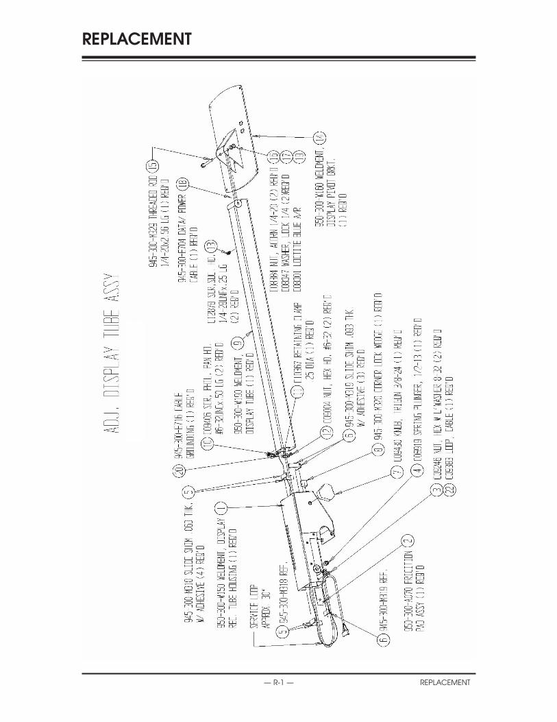
— R-1 — REPLACEMENT
REPLACEMENT
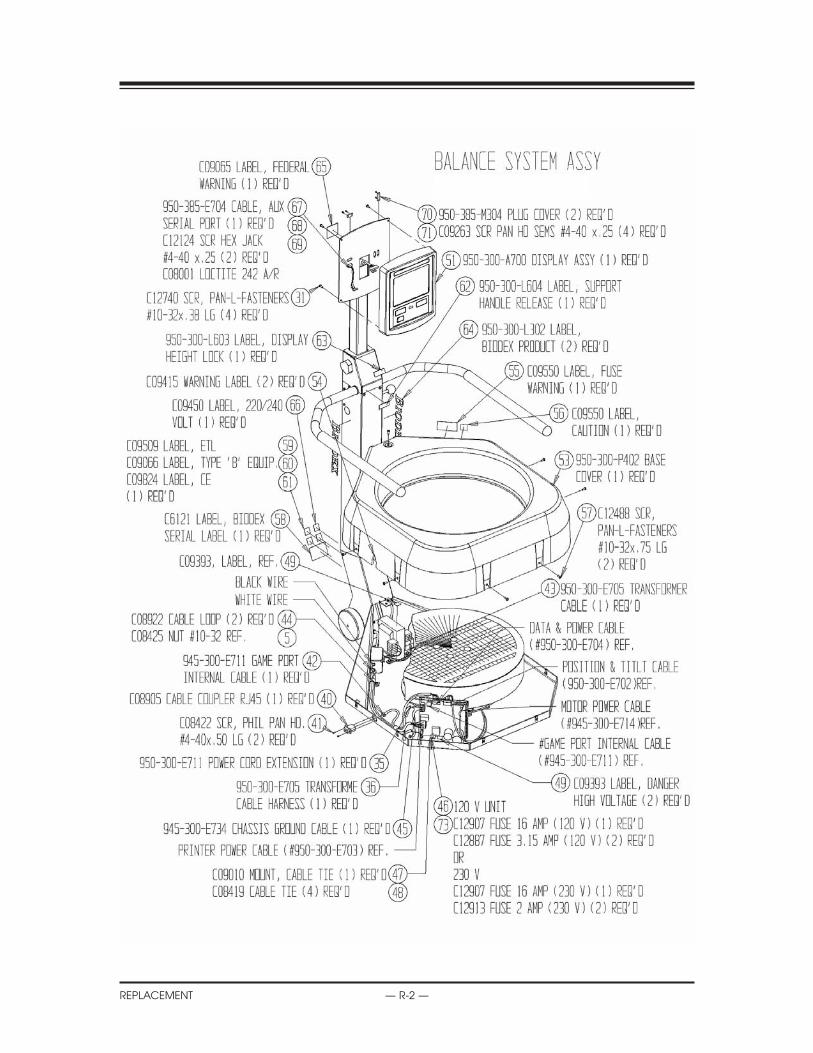
REPLACEMENT
REPLACEMENT — R-2 —
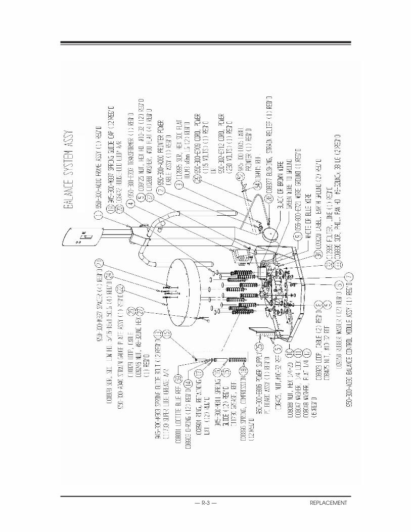
REPLACEMENT PARTS
— R-3 — REPLACEMENT

REPLACEMENT PARTS
REPLACEMENT — R-4 —

REPLACEMENT PARTS
— R-5 — REPLACEMENT
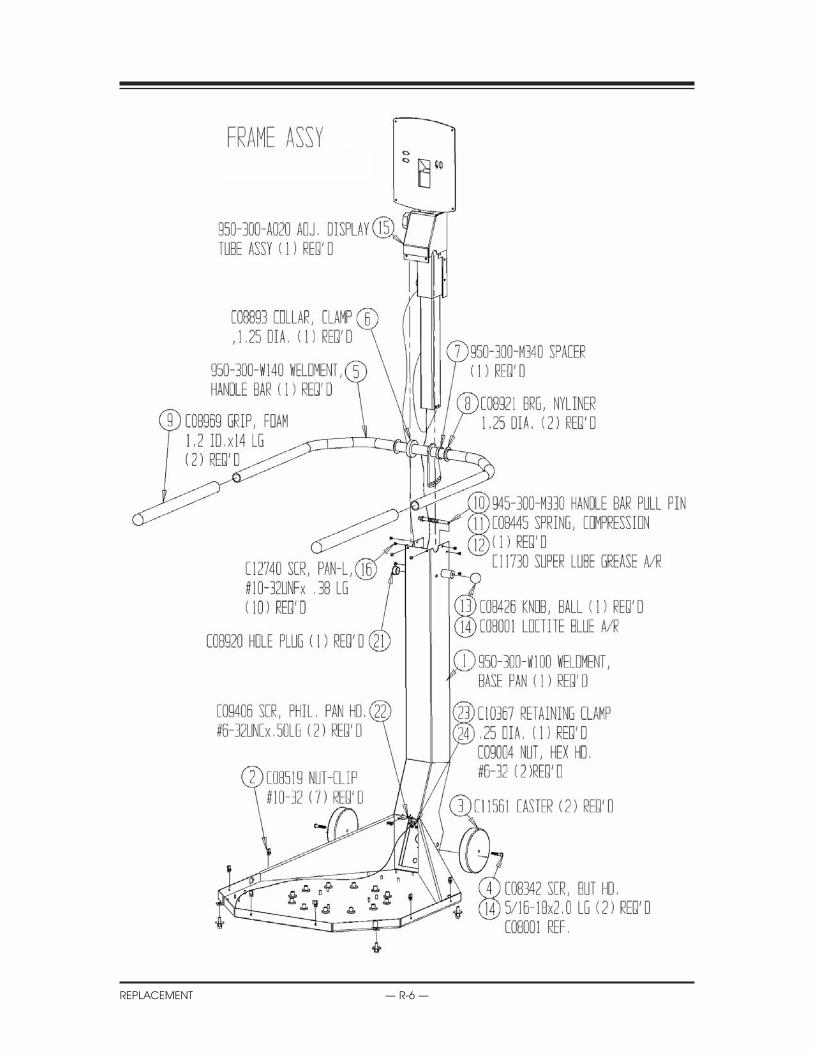
REPLACEMENT PARTS
REPLACEMENT — R-6 —

REPLACEMENT PARTS
— R-7 — REPLACEMENT

REPLACEMENT PARTS
REPLACEMENT — R-8 —

BIODEXBiodex Medical Systems, Inc.
20 Ramsay Road, Shirley, New York, 11967-4704, Tel: 800-224-6339 (Int’l 631-924-9000), Fax: 631-924-9338, Email: [email protected], www.biodex.com
Certified Quality Management System