ba377e-ss rugged one input intrinsically safe timer …€¦ · rugged one input intrinsically safe...
TRANSCRIPT
Issue: 327th April 2017
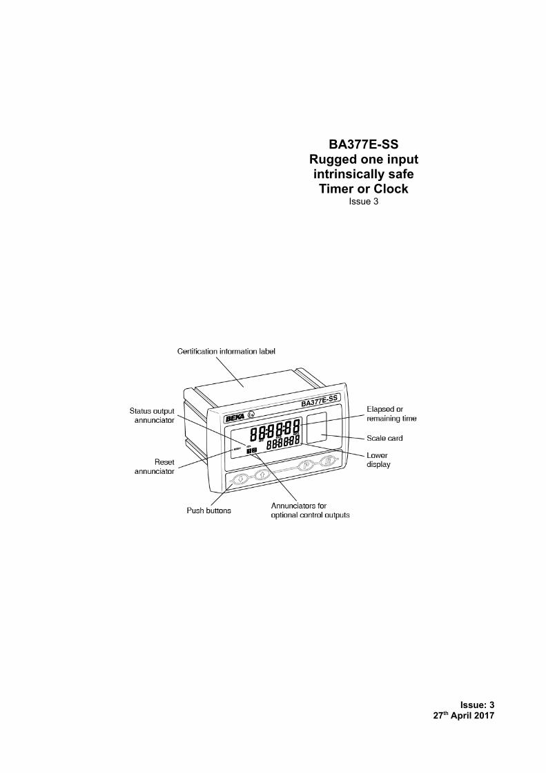
BA377E-SSRugged one inputintrinsically safeTimer or Clock
Issue 3

2
1. DESCRIPTION
2. INTRINSIC SAFETY CERTIFICATION2.1 ATEX gas certification2.2 Zones, gas groups and T rating2.3 Special conditions for safe use2.4 Power supply2.5 Input terminals
2.5.1 Sensors that do not requireenergising.
2.5.2 Sensors that require energising2.6 Remote reset terminals2.7 Control outputs - optional2.8 Certification label information
3. SYSTEM DESIGN FOR HAZARDOUS AREAS3.1 Use with Zener barriers
3.1.1 Power supply3.1.2 Sensor inputs3.1.3 Switch contact input3.1.4 Open collector input3.1.5 2-wire proximity detector input3.1.6 Magnetic pick-off input3.1.7 Voltage pulse input3.1.8 Remote reset3.1.9 Control outputs - optional
3.2 Use with Galvanic Isolators3.2.1 Power supply3.2.2 Sensor inputs3.2.3 Switch contact input3.2.4 Open collector input3.2.5 2-wire proximity detector input3.2.6 Magnetic pick-off input3.2.7 Voltage input3.2.8 Remote reset3.2.9 Control outputs - optional
3.3 Use in an Ex e or Ex p panel enclosure in Zone 1 or Zone 2.3.3.1 Installation in an Ex e panel
enclosure within Zone 1 or Zone 2.3.3.2 Installation in an Ex p panel
enclosure within Zone 1 or Zone 2.
4. INSTALLATION4.1 Location4.2 Installation procedure4.3 EMC4.4 Timer or clock earthing5.5 Scale card
5. ACCESSORIES5.1 Display backlight5.2 Control outputs5.3 Scale card5.4 Tag information
6. OPERATION AS A TIMER6.1 Initialisation6.2 Controls when configured as a Timer6.3 Displays when configured as a Timer6.4 Timer structure6.5 Configuration as a Timer
6.5.1 Accessing configuration functions6.5.2 Summary of Timer configuration
functions.6.5.3 Instrument function: FunCtion
6.5.4 Input: inPut
6.5.5 Input type: inP . tYPE
6.5.6 debounce: debounce
6.5.7 Lower display: di5P-2
6.5.8 Starting & stopping the Timer: 5tAr5toP
6.5.9 Units of display: unit5
6.5.10 Set time: 5Et t
6.5.11 Repeat timing cycle: CYCLE5
6.5.12 Cycle function enable: EnbL
6.5.13 Cycle count: cycl cnt
6.5.14 Restart delay: r5t dela
6.5.15 Adjusting the set time 5Et t and restart delay r5t dela from the display mode: AC5Et t
6.5.16 Direction of count: uP or dn
6.5.17 Power fail: p fail
6.5.18 Local reset: LoC rEt
6.5.19 Local total reset: rE5Et . enbl
6.5.20 Local grand total reset: clr Gtot
6.5.21 Control output 1 (Optional): oP1
6.5.22 Control output 1 enable: EnbL
6.5.23 Control output on at: oP1 on
6.5.24 Control output off at: oP1 oFF
6.5.25 Output on delay time: oP1 dELA
6.5.26 Control output 2 (Optional): oP2
6.5.27 Reset grand total from within the configuration menu: Clr Gtot
6.5.28 Security code: CodE
6.5.29 Reset configuration to Timer factory defaults: r5Et dEF
7. TIMER APPLICATION EXAMPLES7.1 Measuring the time that a contact is closed7.2 Controlling an IS solenoid valve7.3 Cycling an IS solenoid valve
CONTENTS
The BA377E-SS is CE marked to show compliance with the European Explosive Atmospheres Directive2014/34/EU and the European EMC Directive 2014/34/EU

3
8 MAINTENANCE when configured as a Timer8.1 Fault finding during commissioning8.2 Fault finding after commissioning8.3 Servicing8.4 Routine maintenance8.5 Guarantee8.6 Customer comments
9. OPERATION AS A CLOCK9.1 Initialisation and loss of power9.2 Controls when configured as a clock9.3 Displays when configured as a clock9.4 Configration as a clock
9.4.1 Accessing configuration functions9.4.2 Summary of Clock configuration
functions.9.4.3 Instrument function: FunCtion
9.4.4 Display format: di5PLAY
9.4.5 Set Clock display time: 5et
9.4.6 Enter synchronising time: 5YnC t
9.4.7 Control output 1 (Optional): oP1
9.4.8 Enable Control output 1: EnbL
9.4.9 On and off times:oP 1 : on 1; oP 1 : off 1
oP 1 : on 2; oP 1 : off 2
9.4.10 Control output 2 (Optional): oP2
9.4.11 Enable control output 2: EnbL
9.4.12 On and off times:oP2 : on 1; oP2 : off 1
oP2 : on 2; oP2 : off 2
9.4.13 Access on & off times from display mode: AC5P
9.4.14 Security code: CodE
9.4.15 Reset configuration to Clock factory defaults: r5Et dEF
10. CLOCK CONFIGURATION EXAMPLE10.1 Configuration procedure
11. MAINTENANCE when configured as a Clock11.1 Fault finding during commissioning11.2 Fault finding after commissioning11.3 Servicing11.4 Routine maintenance11.5 Guarantee11.6 Customer comments
Appendix 1 ATEX Dust certification
Appendix 2 IECEx certification
Appendix 3 ETL and cETL certification

4
1. DESCRIPTIONThe BA377E-SS is a rugged intrinsically safe, panelmounting instrument with a single input that can beconfigured as a Timer or as a Clock. As a Timer theBA377E-SS is able to measure and display theelapsed time between external events, or controlexternal events via two optional factory fitted controloutputs.
When configured as a Clock, the instrument candisplay time in a variety of formats and the twooptional control outputs may be configured to switchloads on and off at pre-set times.
This instruction manual is divided into sections.
Common features2. Intrinsic safety certification3. System design for hazardous areas4. Installations5. Accessories
Timer6. Operation as a timer7. Configuration example8. Maintenance
Clock9. Operation as a clock
10. Configuration example11. Maintenance
The BA377E-SS has been certified intrinsically safefor use in gas and dust hazardous areas by NotifiedBody Intertek Testing and Certification Ltd andcomplies with the European ATEX Directive2014/34/EU. It has a rugged stainless steelenclosure and an impact resistant glass window. Inaddition to normal intrinsically safe applications, thecertification allows it to be installed in an Ex e, Ex n,Ex p or Ex t panel enclosure without invalidating thepanel enclosure's certification.
The common features sections of this instructionmanual describe ATEX certification for use in gasatmospheres. Dust certification is described inAppendix 1.
For international applications the BA377E-SS hasIECEx certification which is described in Appendix 2.
This instruction manual supplements theabbreviated instruction sheet supplied with eachinstrument.
2. INTRINSIC SAFETY CERTIFICATIONThe BA377E-SS has IECEx and ATEX gascertification. This section of the instruction manualdescribes ATEX gas certification. IECEx and otherapprovals are each described in separateappendixes to this manual. The intrinsic safety ofthe instrument is unaffected by whether it isconfigured as a Timer or as a Clock.
2.1 ATEX gas certificationNotified Body Intertek Testing and Certification Ltdhave issued the BA377E-SS with an EC-TypeExamination Certificate number ITS16ATEX28408X.This confirms compliance with harmonisedEuropean standards and it has been used to confirmcompliance with the European ATEX Directive forGroup II, Category 1G equipment. The Timer orClock carries the European Community mark andsubject to local codes of practice may be installed inany of the European Economic Area (EEA) membercountries. ATEX certificates are also acceptable forinstallations in Switzerland.
This section of the instruction manual describesATEX installations in explosive gas atmospherescomplying with EN60079-14 Electrical InstallationDesign, Selection and Erection. When designingsystems for installation outside the UK the localCode of Practice should be consulted.
2.2 Zones, gas groups and T ratingThe BA377E-SS Timer or Clock has been certifiedEx ia IIC T5 Ga. When connected to a suitablesystem it may be installed in:
Zone 0 explosive gas air mixturecontinuously present.
Zone 1 explosive gas air mixture likelyto occur in normal operation.
Zone 2 explosive gas air mixture notlikely to occur, and if it does will only exist for a short time.
In gases that may be used with equipment having atemperature classification of:
Group A propaneGroup B ethyleneGroup C hydrogen
Having a temperature classification of:T1 450ºCT2 300ºCT3 200ºCT4 135ºCT5 100ºC
5
At ambient temperatures between:-40 to +60oC When installed as an Ex i
intrinsically safe instrument inan Ex e, Ex n, Ex p or Ex t enclosure.
-40 to +70oC When used as an Ex i intrinsically safe instrument not in an Ex e, Ex n, Ex p or Ex t enclosure.
2.3 Special conditions for safe useThe ATEX intrinsic safety certificate number has an‘X’ suffix indicating that for some applications specialconditions apply for safe use.
When installed in an Ex e, Ex n, Ex p or Ex tpanel enclosure all connections to theBA377E-SS must be made by appropriatelyrated Zener barriers or galvanic isolators.
This means that when installed in an Ex e, Ex n,Ex p or Ex t panel enclosure the BA377E-SSremains an intrinsically safe instrument and mustcomply with the installation requirements shown inthis manual.
The certificate also states:
The front of the stainless steel enclosurecomplies with the requirements for Ex e, Ex nEx p & Ex t type of protection.
Therefore when correctly installed the BA377E-SSTimer or Clock will not invalidate the Ex e, Ex n, Ex por Ex t panel enclosure certification.
Note: At temperatures below -20°C theinstruments will continue to function, but the displayresponse will become slower and the contrast will bereduced.
2.4 Power supplyWhen installed in a hazardous area the BA377E-SSmust be powered via a certified Zener barrier orgalvanic isolator from a dc supply located in the safearea, or from certified associated apparatus with anintrinsically safe output.
The input safety parameters of the BA377E-SSpower supply terminals 1 and 2 are:
Ui = 28V dcIi = 200mA dcPi = 0.84W
Any certified Zener barrier or galvanic isolator withoutput safety parameters equal to or less than theselimits may be used to power the BA377E-SS.
The maximum equivalent capacitance andinductance between terminals 1 and 2 is:
Ci = 2nFLi = 4µH
To determine the maximum permissible powersupply cable parameters the above figures, whichare small and may be ignored for many applications,should be subtracted from the maximum permittedparameters, Co and Lo, specified for the Zenerbarrier or galvanic isolator powering theBA377E-SS.
2.5 Input terminalsWhen configured as a Timer the BA377E-SS iscontrolled via a single input that may be configuredfor use with different types of sensor. The input is aseparate intrinsically safe circuit, although thenegative side is internally connected to the negativeside of the power supply and the reset terminal RS2.See Fig 15.
Some types of sensor that may be connected to theBA377E-SS input, such as a switch contact or a 2-wire proximity detector, require energising todetermine their state. For sensors requiringenergising fitting an external link between terminals3 & 4 connects an internal 7V, 6mA supply to theinput. Energising is not required when theBA377E-SS input is connected to a voltage inputsource.
Fitting an energising link changes the output safetyparameters of the BA377E-SS input as shown in thefollowing table which also shows the types of sensorrequiring energising (link fitting).
Output safety parameters of input terminals 5 & 6.
Type of input Link* Uo Io PoSwitch contact Yes 10.5V 8.2mA 25mWProximity detector Yes 10.5V 8.2mA 25mWOpen collector Yes 10.5V 8.2mA 25mWMagnetic pick-off No 1V 11µA 3µWVoltage input (low) No 1V 11µA 3µWVoltage input (high) No 1V 11µA 3µW
*Link terminals 3 and 4
6
2.5.1 Sensors that do not require energisingSensors with a voltage output do not requireenergising, therefore terminals 3 & 4 should not belinked. When not energised i.e. without a link theBA377E-SS pulse input complies with therequirements for simple apparatus. For intrinsicsafety purposes, sources of energy with outputparameters less than 1.5V; 100mA and 25mW areconsidered to be simple apparatus (Clause 5.7 ofEN60079-11), which allows them not to beconsidered or documented when assessing thesafety of an intrinsically safe system, thus simplifyingloop assessment.
This allows almost any voltage output sensor to bedirectly connected to the BA377E-SS pulse input ina hazardous area providing that:
a. The sensor is a certified intrinsically safe devicehaving output parameters equal to or less than:
Uo ≤ 28V dcIo ≤ 200mA dcPo ≤ 0.84W
or complies with requirements for simple apparatus.
b. The sensor and associated wiring canwithstand a 500V rms insulation test to earth.
c. The sensor is located in the same hazardousarea as the BA377E-SS.
The BA377E-SS EC-Type Examination Certificatespecifies that the equivalent capacitance andinductance of the BA377E-SS sensor input is:
Ci = 2nFLi = 4µH
To determine the maximum permissible cableparameters these figures should be subtracted fromthe maximum permitted output parameters Lo andCo specified by the certificate for the sensorconnected to the BA377E-SS input terminals. TheBA377E-SS input parameters are small andtherefore unlikely to make a significant difference tothe allowable cable parameters.
2.5.2 Sensors that require energisingSwitch contacts, proximity detectors and opencollector sensors require energising which isachieved by linking two BA377E-SS terminalstogether as described in section 2.5. Whenenergised, the output parameters of the BA377E-SSinput are:
Uo = 10.5V dcIo = 8.2mA dcPo = 25mW
These parameters do not comply with therequirements for simple apparatus and should beconsidered when assessing the safety of the sensorconnected to a BA377E-SS input.
Any certified intrinsically safe sensor may beconnected to the BA377E-SS energised inputproviding that the sensor's input safety parametersare equal to, or greater than, the output safetyparameters of the BA377E-SS input shown above.This is not restrictive and most intrinsically safesensors will comply. A sensor complying with therequirements for simple apparatus, such as amechanically operated switch contact, may also beconnected.
This allows most mechanically operated switches,open collector transistors and certified intrinsicallysafe NAMUR proximity detectors to be directlyconnected to the BA377E-SS energised input. Thesensor and wiring should be able to withstand a500V rms insulation test to earth and the sensorshould be located in the same hazardous area asthe BA377E-SS.
The BA377E-SS EC-Type Examination Certificatespecifies that the maximum capacitance andinductance that may be safely connected to theenergised input (link connected) is:
Co = 2.4µFLo = 200mH
Again this is not restrictive as the combinedcapacitance and inductance of most sensors andconnecting cable will be less than this.
7
2.6 Remote reset terminalsConnecting the external reset terminals RS1 andRS2 together will reset the BA377E-SS whenconfigured as a Timer and synchronise the displayedtime when configured as a Clock. The two resetterminals have the following input and output safetyparameters:
Uo = 3.8V dcIo = 1.6mA dcPo = 2.0mW
Ui = 28V dcIi = 200mA dcPi = 0.84W
The equivalent capacitance and inductance betweenthem is:
Ci = 0nFLi = 0µH
The maximum cable capacitance and inductancethat may be safely connected between the resetterminals RS1 and RS2 is:
Co = 40µFLo = 1H
The reset terminals may be directly connected toany mechanically operated switch located within thesame hazardous area as the BA377E-SS. Theswitch and associated wiring should be able towithstand a 500V insulation test to earth.
If the reset switch is required in the safe area aZener barrier or intrinsically safe relay is required totransfer the contact closure into the hazardous area.A diode return barrier is not suitable for thisapplication. Almost any intrinsically safe relay withcertification permitting the contacts to be connectedto equipment in the hazardous area may be used.
When used as a Timer the BA377E-SS may also bereset from the display mode by operating the & and* push buttons simultaneously for more than twoseconds. See 6.5.19
2.7 Control outputs - optionalEach of the two factory fitted optional control outputsis a separate galvanically isolated intrinsically safecircuit with output safety parameters complying withthe requirements for simple apparatus. This allowsthe control output terminals A1 & A2 and A3 & A4 tobe connected to almost any intrinsically safe circuitprotected by a Zener barrier or galvanic isolatorproviding the output safety parameters of the circuitdo not exceed:
Uo ≤ 28V dcIo ≤ 200mA dcPo ≤ 0.84W
The maximum equivalent capacitance andinductance between each set of control outputterminals is:
Ci = 22nFLi = 8µH
To determine the maximum permissible cablecapacitance Ci should be subtracted from themaximum permitted external capacitance Cospecified by the certificate for the intrinsically safeinterface powering the circuit being switched by thecontrol output. See fig 4.
8
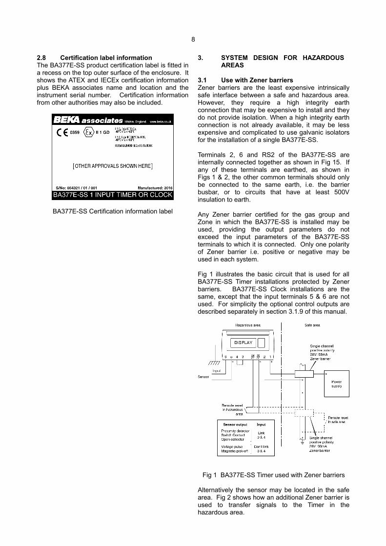
2.8 Certification label informationThe BA377E-SS product certification label is fitted ina recess on the top outer surface of the enclosure. Itshows the ATEX and IECEx certification informationplus BEKA associates name and location and theinstrument serial number. Certification informationfrom other authorities may also be included.
BA377E-SS Certification information label
3. SYSTEM DESIGN FOR HAZARDOUS AREAS
3.1 Use with Zener barriersZener barriers are the least expensive intrinsicallysafe interface between a safe and hazardous area.However, they require a high integrity earthconnection that may be expensive to install and theydo not provide isolation. When a high integrity earthconnection is not already available, it may be lessexpensive and complicated to use galvanic isolatorsfor the installation of a single BA377E-SS.
Terminals 2, 6 and RS2 of the BA377E-SS areinternally connected together as shown in Fig 15. Ifany of these terminals are earthed, as shown inFigs 1 & 2, the other common terminals should onlybe connected to the same earth, i.e. the barrierbusbar, or to circuits that have at least 500Vinsulation to earth.
Any Zener barrier certified for the gas group andZone in which the BA377E-SS is installed may beused, providing the output parameters do notexceed the input parameters of the BA377E-SSterminals to which it is connected. Only one polarityof Zener barrier i.e. positive or negative may beused in each system.
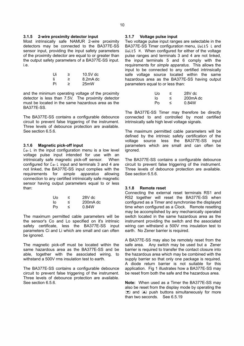
Fig 1 illustrates the basic circuit that is used for allBA377E-SS Timer installations protected by Zenerbarriers. BA377E-SS Clock installations are thesame, except that the input terminals 5 & 6 are notused. For simplicity the optional control outputs aredescribed separately in section 3.1.9 of this manual.
Fig 1 BA377E-SS Timer used with Zener barriers
Alternatively the sensor may be located in the safearea. Fig 2 shows how an additional Zener barrier isused to transfer signals to the Timer in thehazardous area.

9
When more than one Zener barrier is used in asystem all must have the same polarity. i.e. allpositive or all negative barriers. When designing aTimer system it is important to remember thatterminals 2, 6 and RS2 of the BA377E-SS areconnected together within the instrument. Similarly,terminals 2 and RS2 are internally connectedtogether when the BA377E-SS is configured as aClock. See Fig 21.
Fig 2 BA377E-SS Timer used with Zener barriers and input sensor in the safe area.
3.1.1 Power supplyThe BA377E-SS requires a minimum of 10Vbetween terminal 1 & 2 and consumes:
10mA without optional backlightplus 22mA for optional backlightplus 6mA when terminals 3 & 4 are linked
Any Zener barrier certified for the gas group andZone in which the BA377E-SS is installed may beused to power the instrument, providing the outputsafety parameters of the barrier are equal to or lessthan the input safety parameters of terminals 1 & 2.
Although this allows a wide variety of barriers to beused, a positive polarity 28V; 93mA; 300 Zenerbarrier, which has an end-to-end resistance of about340, is an industry standard device which isfrequently used. With this barrier the supply voltagein the safe area must be between the minimumvalue shown below and the maximum workingvoltage of the Zener barrier which, depending uponmanufacturer, will be approximately 26V.
13.5V min without optional backlight20.9V min with optional backlight
plus 2.1V when terminals 3 & 4 are linked
3.1.2 Sensor inputWhen configured as a Timer the sensor input maybe connected to a wide variety of hazardous areadevices as shown in Fig 1, or to safe area sensor asshown in Fig 2. The BA377E-SS input is not usedwhen the instrument is configured as a Clock.
No Zener barrier is required in series with the input ifthe intrinsically safe sensor is located within thesame hazardous area as the BA377E-SS. Thefollowing table shows the instrument's inputswitching thresholds when configured to operatewith various sensors. For reliable operation theBA377E-SS input must fall below the lowerthreshold and rise above the upper threshold.
SensorSwitching thresholds
Lower Upper
Voltage pulse low 1.0V 3.0V
Voltage pulse high 3.0V 10.0V
Magnetic pick-off 0mV 40mV peak
Proximity detector 1.2mA 2.1mA
Switch 100 1000
Open collector 2k 10k
Switch contacts, proximity detectors and opencollector sensors require energising which isachieved by linking terminals 3 and 4 together asdescribed in section 2.5.
3.1.3 Switch contact inputAny mechanically activated switch contact may bedirectly connected to input terminals 5 & 6 providingthe switch is located in the same hazardous area asthe BA377E-SS, and the switch and associatedwiring can withstand a 500V rms insulation test toearth. Most industrial push buttons and magneticallyactivated reed relays comply with theserequirements. The BA377E-SS contains aconfigurable debounce circuit to prevent falsetriggering of the instrument. Three levels ofdebounce protection are available. Seesection 6.5.6.
3.1.4 Open collector inputAny sensor with an open collector output located inthe same hazardous area as the BA377E-SS, suchas a mechanically activated opto-isolator may bedirectly connected to input terminals 5 & 6. Thesensor and the associated wiring must be able towithstand a 500V rms insulation test to earth. TheBA377E-SS contains a configurable debouncecircuit to prevent false triggering. Three levels ofdebounce protection are available. Seesection 6.5.6.
10
3.1.5 2-wire proximity detector inputMost intrinsically safe NAMUR 2-wire proximitydetectors may be connected to the BA377E-SSsensor input, providing the input safety parametersof the proximity detector are equal to or greater thanthe output safety parameters of a BA377E-SS input.i.e.
Ui ≥ 10.5V dcIi ≥ 8.2mA dcPi ≥ 25mW
and the minimum operating voltage of the proximitydetector is less than 7.5V. The proximity detectormust be located in the same hazardous area as theBA377E-SS.
The BA377E-SS contains a configurable debouncecircuit to prevent false triggering of the instrument.Three levels of debounce protection are available.See section 6.5.6.
3.1.6 Magnetic pick-off input CoiL in the input configuration menu is a low levelvoltage pulse input intended for use with anintrinsically safe magnetic pick-off sensor. Whenconfigured for CoiL input and terminals 3 and 4 arenot linked, the BA377E-SS input complies with therequirements for simple apparatus allowingconnection to any certified intrinsically safe magneticsensor having output parameters equal to or lessthan:
Uo ≤ 28V dcIo ≤ 200mA dcPo ≤ 0.84W
The maximum permitted cable parameters will bethe sensor's Co and Lo specified on it's intrinsicsafety certificate, less the BA377E-SS inputparameters Ci and Li which are small and can oftenbe ignored.
The magnetic pick-off must be located within thesame hazardous area as the BA377E-SS and beable, together with the associated wiring, towithstand a 500V rms insulation test to earth.
The BA377E-SS contains a configurable debouncecircuit to prevent false triggering of the instrument.Three levels of debounce protection are available.See section 6.5.6.
3.1.7 Voltage pulse inputTwo voltage pulse input ranges are selectable in theBA377E-SS Timer configuration menu, VoLt5 L andVoLt5 H. When configured for either of the voltagepulse ranges and terminals 3 and 4 are not linked,the input terminals 5 and 6 comply with therequirements for simple apparatus. This allows theinput to be connected to any certified intrinsicallysafe voltage source located within the samehazardous area as the BA377E-SS having outputparameters equal to or less than:
Uo ≤ 28V dcIo ≤ 200mA dcPo ≤ 0.84W
The BA377E-SS Timer may therefore be directlyconnected to and controlled by most certifiedintrinsically safe high level voltage signals.
The maximum permitted cable parameters will bedefined by the intrinsic safety certification of thevoltage source less the BA377E-SS inputparameters which are small and can often beignored.
The BA377E-SS contains a configurable debouncecircuit to prevent false triggering of the instrument.Three levels of debounce protection are available.See section 6.5.6.
3.1.8 Remote resetConnecting the external reset terminals RS1 andRS2 together will reset the BA377E-SS whenconfigured as a Timer and synchronise the displayedtime when configured as a Clock. Remote resettingmay be accomplished by any mechanically operatedswitch located in the same hazardous area as theinstrument providing the switch and the associatedwiring can withstand a 500V rms insulation test toearth. No Zener barrier is required.
A BA377E-SS may also be remotely reset from thesafe area. Any switch may be used but a Zenerbarrier is required to transfer the contact closure intothe hazardous area which may be combined with thesupply barrier so that only one package is required.A diode return barrier is not suitable for thisapplication. Fig 1 illustrates how a BA377E-SS maybe reset from both the safe and the hazardous area.
Note: When used as a Timer the BA377E-SS mayalso be reset from the display mode by operating the& and * push buttons simultaneously for morethan two seconds. See 6.5.19
11
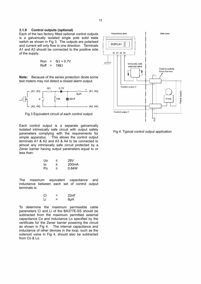
3.1.9 Control outputs (optional)Each of the two factory fitted optional control outputsis a galvanically isolated single pole solid stateswitch as shown in Fig 3. The outputs are polarisedand current will only flow in one direction. TerminalsA1 and A3 should be connected to the positive sideof the supply.
Ron < 5 + 0.7VRoff > 1M
Note: Because of the series protection diode sometest meters may not detect a closed alarm output
Fig 3 Equivalent circuit of each control output
Each control output is a separate galvanicallyisolated intrinsically safe circuit with output safetyparameters complying with the requirements forsimple apparatus. This allows the control outputterminals A1 & A2 and A3 & A4 to be connected toalmost any intrinsically safe circuit protected by aZener barrier having output parameters equal to orless than:
Uo ≤ 28VIo ≤ 200mAPo ≤ 0.84W
The maximum equivalent capacitance andinductance between each set of control outputterminals is:
Ci = 22nFLi = 8µH
To determine the maximum permissible cableparameters Ci and Li of the BA377E-SS should besubtracted from the maximum permitted externalcapacitance Co and inductance Lo specified by thecertificate for the Zener barrier powering the circuitas shown in Fig 4. The internal capacitance andinductance of other devices in the loop, such as thesolenoid valve in Fig 4, should also be subtractedfrom Co & Lo.
Fig 4 Typical control output application
12
3.2 Use with Galvanic IsolatorsGalvanic isolators are probably the simplestintrinsically safe interface to install as they provideisolation and do not require a high integrity earthconnection.
Any galvanic isolator certified for the gas group inwhich the BA377E-SS is installed, with outputparameters less than the input parameters of theBA377E-SS having the correct function may beused.
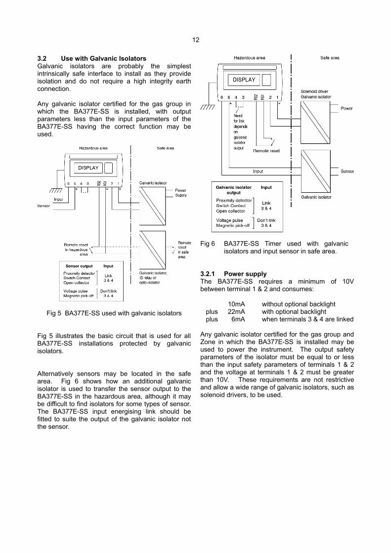
Fig 5 BA377E-SS used with galvanic isolators
Fig 5 illustrates the basic circuit that is used for allBA377E-SS installations protected by galvanicisolators.
Alternatively sensors may be located in the safearea. Fig 6 shows how an additional galvanicisolator is used to transfer the sensor output to theBA377E-SS in the hazardous area, although it maybe difficult to find isolators for some types of sensor.The BA377E-SS input energising link should befitted to suite the output of the galvanic isolator notthe sensor.
Fig 6 BA377E-SS Timer used with galvanic isolators and input sensor in safe area.
3.2.1 Power supplyThe BA377E-SS requires a minimum of 10Vbetween terminal 1 & 2 and consumes:
10mA without optional backlightplus 22mA with optional backlightplus 6mA when terminals 3 & 4 are linked
Any galvanic isolator certified for the gas group andZone in which the BA377E-SS is installed may beused to power the instrument. The output safetyparameters of the isolator must be equal to or lessthan the input safety parameters of terminals 1 & 2and the voltage at terminals 1 & 2 must be greaterthan 10V. These requirements are not restrictiveand allow a wide range of galvanic isolators, such assolenoid drivers, to be used.

13
3.2.2 Sensor inputsAs shown in Fig 5 the BA377E-SS input can bedirectly connected to hazardous area sensor, or tosafe area sensors via isolators as shown in Fig 6.Galvanic isolators are not required in series with theinput if the intrinsically safe sensor is located withinthe same hazardous area as the BA377E-SS.
The BA377E-SS may be used with a wide variety ofsensors, the following table shows the switchingthresholds for each type. For reliable operation theinput signal must fall below the lower threshold andrise above the upper threshold.
SensorSwitching thresholds
Lower Upper
Voltage pulse low 1.0V 3.0V
Voltage pulse high 3.0V 10.0V
Magnetic pick-off 0mV 40mV peak
Proximity detector 1.2mA 2.1mA
Switch 100 1000
Open collector 2k 10k
Switch contacts, proximity detectors and opencollector sensors require energising which isachieved by linking two BA377E-SS terminalstogether as described in section 2.5.
3.2.3 Switch contact inputAny mechanically activated switch contact may bedirectly connected to input terminals 5 & 6 providingthe switch is located in the same hazardous area asthe BA377E-SS, and the switch and associatedwiring can withstand a 500V rms insulation test toearth. Most magnetically activated industrial pushbuttons and reed relays comply with theserequirements. The BA377E-SS contains aconfigurable debounce circuit to prevent falsetriggering of the instrument. Three levels ofdebounce protection are available. Seesection 6.5.6
3.2.4 Open collector inputAny open collector sensor located in the samehazardous area as the BA377E-SS, such as amechanically activated opto-isolator, may be directlyconnected to input terminals 5 & 6. The sensor andthe associated wiring must be able to withstand a500V rms insulation test to earth.
The BA377E-SS contains a configurable debouncecircuit to prevent false triggering. Three levels ofdebounce protection are available See section 6.5.6
3.2.5 2-wire proximity detector inputMost intrinsically safe NAMUR 2-wire proximitydetectors may be connected to the BA377E-SSinput, providing the input safety parameters of theproximity detector are equal to or greater than theoutput safety parameters of a BA377E-SS input. i.e.
Ui ≥ 10.5V dcIi ≥ 8.2mA dcPi ≥ 25mW
and the minimum operating voltage of the proximitydetector is less than 7.5V. The proximity detectormust be located in the same hazardous area as theBA377E-SS.
The BA377E-SS contains a configurable debouncecircuit to prevent false triggering of the instrument.Three levels of debounce protection are available.See section 6.5.6
3.2.6 Magnetic pick-off inputCoiL in the input configuration menu is a low levelvoltage pulse input intended for use with anintrinsically safe magnetic pick-off sensor. Whenconfigured for CoiL input and terminals 3 and 4 arenot linked, the BA377E-SS input complies with therequirements for simple apparatus allowingconnection to any certified intrinsically safe magneticsensor having output parameters equal to or lessthan:
Uo ≤ 28V dcIo ≤ 200mA dcPo ≤ 0.84W
The maximum permitted cable parameters will bethe sensor's Co and Lo specified on it's intrinsicsafety certificate, less the BA377E-SS inputparameters Ci and Li which are small and can oftenbe ignored.
The magnetic pick-off must be located within thesame hazardous area as the BA377E-SS and withthe associated wiring be able to withstand a 500Vrms insulation test to earth.
The BA377E-SS contains a configurable debouncecircuit to prevent false triggering of the instrument.Three levels of debounce protection are available.See section 6.5.6.
14
3.2.7 Voltage inputTwo voltage input ranges are independentlyselectable in the BA377E-SS configuration menu,VoLt5 L and VoLt5 H. When configured for either ofthe voltage pulse ranges and terminals 3 and 4 arenot linked, the input terminals 5 and 6 comply withthe requirements for simple apparatus. This allowsthe inputs to be connected to any certifiedintrinsically safe voltage source within the samehazardous area as the BA377E-SS having outputparameters equal to or less than:
Uo ≤ 28V dcIo ≤ 200mA dcPo ≤ 0.84W
The BA377E-SS Timer may therefore be directlyconnected to and controlled by most certifiedintrinsically safe high level outputs.
The maximum permitted cable parameters will bedefined by the intrinsic safety certification of thevoltage source less the BA377E-SS inputparameters which are small and can often beignored.
The BA377E-SS contains a configurable debouncecircuit to prevent false triggering of the instrument.Three levels of debounce protection are available.See section 6.5.6
3.2.8 Remote resetConnecting the external reset terminals RS1 andRS2 together will reset the BA377E-SS whenconfigured as a Timer and synchronise the displayedtime when configured as a Clock. Remote resettingmay be accomplished by any mechanically operatedswitch located in the same hazardous area as theinstrument providing the switch and the associatedwiring can withstand a 500V rms insulation test toearth. No galvanic isolator is required.
A BA377E-SS may also be remotely reset orsynchronised from the safe area. Any switch maybe used but a galvanic isolator or IS relay is requiredto transfer the contact closure into the hazardousarea. Fig 5 illustrates how a BA377E-SS Timer maybe reset from both the safe and the hazardous area.
Note: The BA377E-SS can also be configured toreset when the & and * push buttons areoperated simultaneously in the display mode formore than two seconds - see 6.5.19
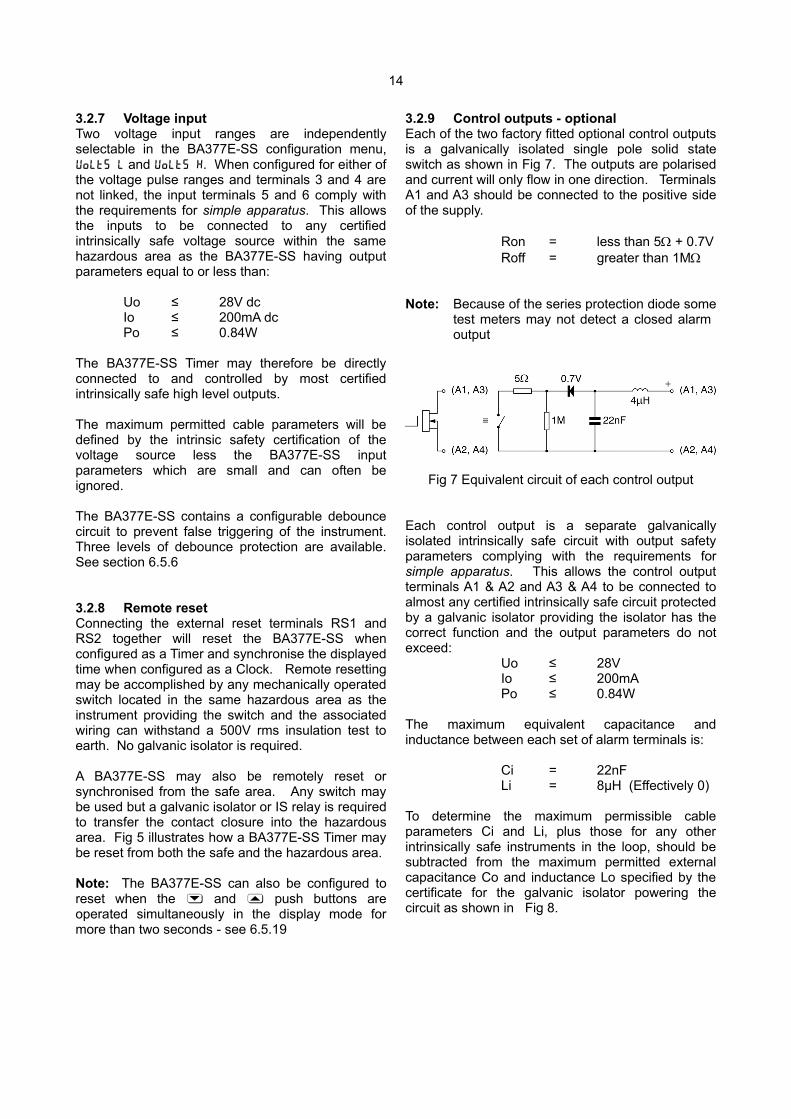
3.2.9 Control outputs - optionalEach of the two factory fitted optional control outputsis a galvanically isolated single pole solid stateswitch as shown in Fig 7. The outputs are polarisedand current will only flow in one direction. TerminalsA1 and A3 should be connected to the positive sideof the supply.
Ron = less than 5 + 0.7VRoff = greater than 1M
Note: Because of the series protection diode sometest meters may not detect a closed alarm output
Fig 7 Equivalent circuit of each control output
Each control output is a separate galvanicallyisolated intrinsically safe circuit with output safetyparameters complying with the requirements forsimple apparatus. This allows the control outputterminals A1 & A2 and A3 & A4 to be connected toalmost any certified intrinsically safe circuit protectedby a galvanic isolator providing the isolator has thecorrect function and the output parameters do notexceed:
Uo ≤ 28VIo ≤ 200mAPo ≤ 0.84W
The maximum equivalent capacitance andinductance between each set of alarm terminals is:
Ci = 22nFLi = 8µH (Effectively 0)
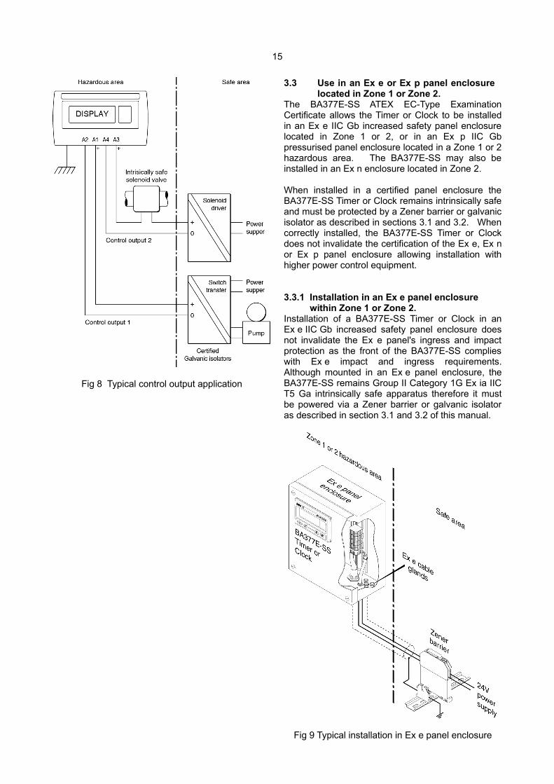
To determine the maximum permissible cableparameters Ci and Li, plus those for any otherintrinsically safe instruments in the loop, should besubtracted from the maximum permitted externalcapacitance Co and inductance Lo specified by thecertificate for the galvanic isolator powering thecircuit as shown in Fig 8.
15
Fig 8 Typical control output application
3.3 Use in an Ex e or Ex p panel enclosure located in Zone 1 or Zone 2.
The BA377E-SS ATEX EC-Type ExaminationCertificate allows the Timer or Clock to be installedin an Ex e IIC Gb increased safety panel enclosurelocated in Zone 1 or 2, or in an Ex p IIC Gbpressurised panel enclosure located in a Zone 1 or 2hazardous area. The BA377E-SS may also beinstalled in an Ex n enclosure located in Zone 2.
When installed in a certified panel enclosure theBA377E-SS Timer or Clock remains intrinsically safeand must be protected by a Zener barrier or galvanicisolator as described in sections 3.1 and 3.2. Whencorrectly installed, the BA377E-SS Timer or Clockdoes not invalidate the certification of the Ex e, Ex nor Ex p panel enclosure allowing installation withhigher power control equipment.
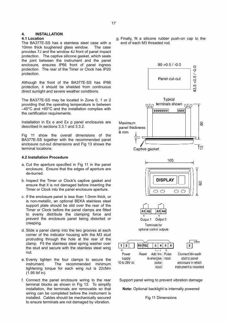
3.3.1 Installation in an Ex e panel enclosure within Zone 1 or Zone 2. Installation of a BA377E-SS Timer or Clock in anEx e IIC Gb increased safety panel enclosure doesnot invalidate the Ex e panel's ingress and impactprotection as the front of the BA377E-SS complieswith Ex e impact and ingress requirements.Although mounted in an Ex e panel enclosure, theBA377E-SS remains Group II Category 1G Ex ia IICT5 Ga intrinsically safe apparatus therefore it mustbe powered via a Zener barrier or galvanic isolatoras described in section 3.1 and 3.2 of this manual.
Fig 9 Typical installation in Ex e panel enclosure

16
Some Zener barriers and galvanic isolators arecertified for mounting within a protective enclosurelocated in Zone 2 which may permit them to bemounted in the same Ex e enclosure as theBA377E-SS Timer or Clock. Zener barriers andgalvanic isolators are not permitted in Ex eenclosures located in Zone 1.
The Timer or Clock terminals, the wiring to the Timeror Clock and the intrinsically safe interface, ifmounted within the enclosure, should be segregatedfrom all other non-intrinsically safe wiring andequipment within the panel enclosure as required byEN 60079-11 Equipment protected by intrinsic safetyand EN 60079-14 Electrical installations design,selection and erection.
The Ex e panel enclosure should be fitted with awarning label saying 'Do not open when non-intrinsically safe circuits are energised', alternativelyall bare live non-intrinsically safe parts within thepanel enclosure should have an IP30 cover carryinga warning label 'Do not open when energised'.
The power dissipation within an BA377E-SS fittedwith operational alarms and a backlight is normallyabout 350mW. In the very unlikely event that allthree circuits fail to the worst case condition at thesame time, the total power dissipation rises to 2.5Wwhich could raise the internal temperature of a smallthermally well insulated panel enclosure.
3.3.2 Installation in Ex p panel enclosure within Zone 1 or Zone 2. Installation of a BA377E-SS Timer or Clock in anEx p IIC Gb or Ex p IIC Gc pressurised panelenclosure does not invalidate the Ex p panel'simpact and ingress protection as the front of theTimer or Clock complies with Ex p impact andingress requirements. Although mounted in an Ex ppanel enclosure, the BA377E-SS remains Group IICategory 1G Ex ia IIC T5 Ga intrinsically safeapparatus and must therefore be powered via aZener barrier or galvanic isolator as described insection 3.1 and 3.2 of this manual.
When installed in an Ex p panel enclosure the fourvents at the rear of the Timer or Clock which areshown in Fig 13 should not be obstructed.
Zener barriers and galvanic isolators may beinstalled in the same Ex p enclosure as theBA377E-SS. All may be mounted in an Ex pxenclosure installed in Zones 1 or 2, or in an Ex pzenclosure installed in Zone 2, both of which have anon-hazardous interior. Some Zener barriers andgalvanic isolators may have certification permittinginstallation within an Ex py enclosure which has aZone 2 interior.
The Timer or Clock's terminals, the wiring to theTimer or Clock and the intrinsically safe interface, ifmounted within the enclosure, should be segregatedfrom all other non-intrinsically safe wiring andequipment within the panel enclosure as required byEN 60079-11 Equipment protected by intrinsic safetyand EN 60079-14 Electrical installations design,selection and erection.
If live maintenance is anticipated, it is recommendedthat the Ex p panel enclosure should be fitted with awarning label saying 'Do not open when non-intrinsically safe circuits are energised', alternativelyall bare live non-intrinsically safe parts within thepanel enclosure should have an IP30 cover carryinga warning label 'Do not open when energised'.
Fig 10 Typical installation in Ex p panel enclosure
17
4. INSTALLATION4.1 LocationThe BA377E-SS has a stainless steel case with a10mm thick toughened glass window. The caseprovides 7J and the window 4J front of panel impactprotection. The captive silicone gasket, which sealsthe joint between the instrument and the panelenclosure, ensures IP66 front of panel ingressprotection. The rear of the Timer or Clock has IP20protection.
Although the front of the BA377E-SS has IP66protection, it should be shielded from continuousdirect sunlight and severe weather conditions.
The BA377E-SS may be located in Zone 0, 1 or 2providing that the operating temperature is between–40°C and +60°C and the installation complies withthe certification requirements.
Installation in Ex e and Ex p panel enclosures aredescribed in sections 3.3.1 and 3.3.2.
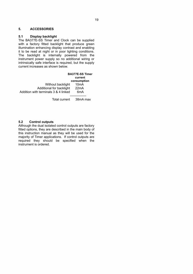
Fig 11 show the overall dimensions of theBA377E-SS together with the recommended panelenclosure cut-out dimensions and Fig 13 shows theterminal locations.
4.2 Installation Procedure
a. Cut the aperture specified in Fig 11 in the panelenclosure. Ensure that the edges of aperture arede-burred.
b. Inspect the Timer or Clock's captive gasket andensure that it is not damaged before inserting theTimer or Clock into the panel enclosure aperture.
c. If the enclosure panel is less than 1.0mm thick, oris non-metallic, an optional BEKA stainless steelsupport plate should be slid over the rear of theTimer or Clock before the panel clamps are fittedto evenly distribute the clamping force andprevent the enclosure panel being distorted orcreeping.
d. Slide a panel clamp into the two grooves at eachcorner of the indicator housing with the M3 studprotruding through the hole at the rear of theclamp. Fit the stainless steel spring washer overthe stud and secure with the stainless steel wingnut.
e. Evenly tighten the four clamps to secure theinstrument. The recommended minimumtightening torque for each wing nut is 22cNm(1.95 lbf in).
f. Connect the panel enclosure wiring to the rearterminal blocks as shown in Fig 13. To simplifyinstallation, the terminals are removable so thatwiring can be completed before the instrument isinstalled. Cables should be mechanically securedto ensure terminals are not damaged by vibration.
g. Finally, fit a silicone rubber push-on cap to theend of each M3 threaded rod.
Support panel wiring to prevent vibration damage
Note: Optional backlight is internally powered
Fig 11 Dimensions

18
Fig 12 Installation procedure
4.3 EMCThe BA377E-SS complies with the requirements ofthe European EMC Directive 2014/34/EU. Forspecified immunity all wiring should be in screenedtwisted pairs, with the screens earthed at one pointwithin the safe area.
Fig 13 terminal
4.4 Timer or Clock earthingThe BA377E-SS has an M4 earth stud on the rearpanel which should be electrically connected to thepanel enclosure in which the indicator is mounted, orto the plant equipotential conductor.
4.5 Scale cardThe Timer or Clock’s units of measurement areshown on a printed scale card in a window at theright hand side of the display. The scale card ismounted on a flexible strip that is inserted into a slotat the rear of the instrument as shown in Fig 14.Thus the scale card can easily be changed withoutremoving the Timer or Clock from the panel oropening the instrument enclosure.
New Timer or Clocks are supplied with a printedscale card showing the requested units ofmeasurement, if this information is not suppliedwhen the instrument is ordered a blank card will befitted.
A pack of self-adhesive scale cards printed withcommon units of flow measurement is available asan accessory from BEKA associates. Customprinted scale cards can also be supplied.
To change a scale card, unclip the tapered end ofthe flexible strip at the rear of the instrument bygently pushing it upwards and pulling it out of theenclosure. Peel the existing scale card from theflexible strip and replace it with a new printed card,which should be aligned as shown below. Do not fita new scale card on top of an existing card.
Install the new scale card by gently pushing theflexible strip into the slot at the rear of the Timer orClock, when it reaches the internal end-stop secureit by pushing the end of the flexible strip downwardsso that the tapered section is held by the rear panel.
Align the self-adhesiveprinted scale card onto theflexible strip and insert thestrip into the indicator asshown below.
Fig 14 Inserting the flexible strip carrying the scalecard into the slot at rear of instrument.
19
5. ACCESSORIES
5.1 Display backlightThe BA377E-SS Timer and Clock can be suppliedwith a factory fitted backlight that produce greenillumination enhancing display contrast and enablingit to be read at night or in poor lighting conditions.The backlight is internally powered from theinstrument power supply so no additional wiring orintrinsically safe interface is required, but the supplycurrent increases as shown below.
BA377E-SS Timercurrent
consumptionWithout backlight 10mA
Additional for backlight 22mAAddition with terminals 3 & 4 linked 6mA
---------------Total current 38mA max
5.2 Control outputsAlthough the dual isolated control outputs are factoryfitted options, they are described in the main body ofthis instruction manual as they will be used for themajority of Timer applications. If control outputs arerequired they should be specified when theinstrument is ordered.

20
6. OPERATION AS A TIMERWhen configured as a Timer the BA377E-SS canmeasure and display the elapsed time betweenexternal events such as measuring and displayinghow long machinery is operating. The Timer can bestarted and stopped by a remote sensor, or from thefront panel push buttons.
The addition of two optional factory fitted isolatedcontrol outputs allows the Timer to control externalevents such as opening a valve for a predeterminedtime. Again the Timer can be started and stoppedby a remote sensor, or from the front panel pushbuttons.
When controlling external events the CYCLE functionenables the BA377E-SS Timer to be configured torepeat the timing period up to 99 times with aconfigurable delay between timed periods up to 100hours or to repeat continuously.
The BA377E-SS may be configured to time-up fromzero to the set time 5Et t, or to time-down from theset time to zero. The set time may be entered anddisplayed in hours, minutes or seconds, or acombination of units. Elapsed or remaining time iscontinuously displayed and a separate display maybe activated to show the Timer set time 5Et t.Resetting the timer cycle can be accomplished viathe front panel push buttons or by a remote contact.
A grand total time is maintained which can beviewed by operating the front panel push buttons. Itmay be reset to zero from within the configurationmenu, or the instrument may be configured to allowresetting from the front panel push buttons.
Fig 15 shows a simplified block diagram of theBA377E-SS when configured as a Timer. The inputcan be configured to accept inputs from a widevariety of sensors. When the sensor requiresenergising, such as a switch contact, open collectoror a two wire proximity detector, a link connectedbetween terminals 3 & 4 supplies power to thesensor input.
The instrument can be supplied with the followingfactory fitted accessories:
Internally powered Backlight
Dual isolated Control Outputs
The two factory fitted solid state isolated controloutputs may be independently configured to closeand open at specified parts of the timer cycle, suchas when the timer starts or finishes.
6.1 InitialisationEach time power is applied to a BA377E-SSinitialisation is performed. After a short delay thefollowing display sequence occurs:
All segments of the display are activated
BA377E-SS is ready to start functioningusing the configuration information stored inthe instrument's permanent memory.
Fig 15 BA377E-SS block diagram with Timerconfiguration.
21
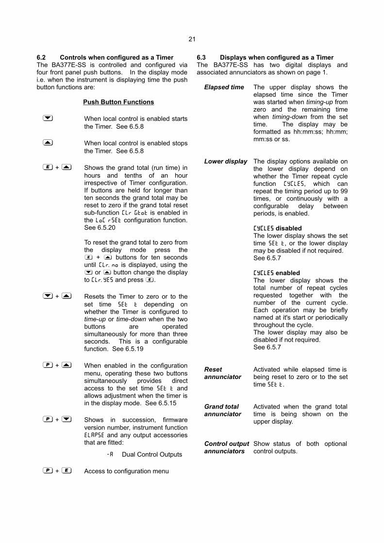
6.2 Controls when configured as a TimerThe BA377E-SS is controlled and configured viafour front panel push buttons. In the display modei.e. when the instrument is displaying time the pushbutton functions are:
Push Button Functions
& When local control is enabled startsthe Timer. See 6.5.8
* When local control is enabled stopsthe Timer. See 6.5.8
) + * Shows the grand total (run time) inhours and tenths of an hourirrespective of Timer configuration.If buttons are held for longer thanten seconds the grand total may bereset to zero if the grand total resetsub-function clr gtot is enabled inthe LoC r5Et configuration function.See 6.5.20
To reset the grand total to zero fromthe display mode press the) + * buttons for ten secondsuntil CLr. no is displayed, using the& or * button change the displayto CLr. YE5 and press ).
& + * Resets the Timer to zero or to theset time 5Et t depending onwhether the Timer is configured totime-up or time-down when the twobuttons are operatedsimultaneously for more than threeseconds. This is a configurablefunction. See 6.5.19
( + * When enabled in the configurationmenu, operating these two buttonssimultaneously provides directaccess to the set time 5Et t andallows adjustment when the timer isin the display mode. See 6.5.15
( + & Shows in succession, firmwareversion number, instrument functionelap5e and any output accessoriesthat are fitted:
-A Dual Control Outputs
( + ) Access to configuration menu
6.3 Displays when configured as a TimerThe BA377E-SS has two digital displays andassociated annunciators as shown on page 1.
Elapsed time The upper display shows theelapsed time since the Timerwas started when timing-up fromzero and the remaining timewhen timing-down from the settime. The display may beformatted as hh:mm:ss; hh:mm;mm:ss or ss.
Lower display The display options available onthe lower display depend onwhether the Timer repeat cyclefunction CYCLE5, which canrepeat the timing period up to 99times, or continuously with aconfigurable delay betweenperiods, is enabled.
CYCLE5 disabledThe lower display shows the settime 5ET t, or the lower displaymay be disabled if not required.See 6.5.7
CYCLE5 enabledThe lower display shows thetotal number of repeat cyclesrequested together with thenumber of the current cycle.Each operation may be brieflynamed at it's start or periodicallythroughout the cycle.The lower display may also bedisabled if not required.See 6.5.7
Reset Activated while elapsed time isannunciator being reset to zero or to the set
time 5ET t.
Grand total Activated when the grand totalannunciator time is being shown on the
upper display.
Control output Show status of both optionalannunciators control outputs.
22
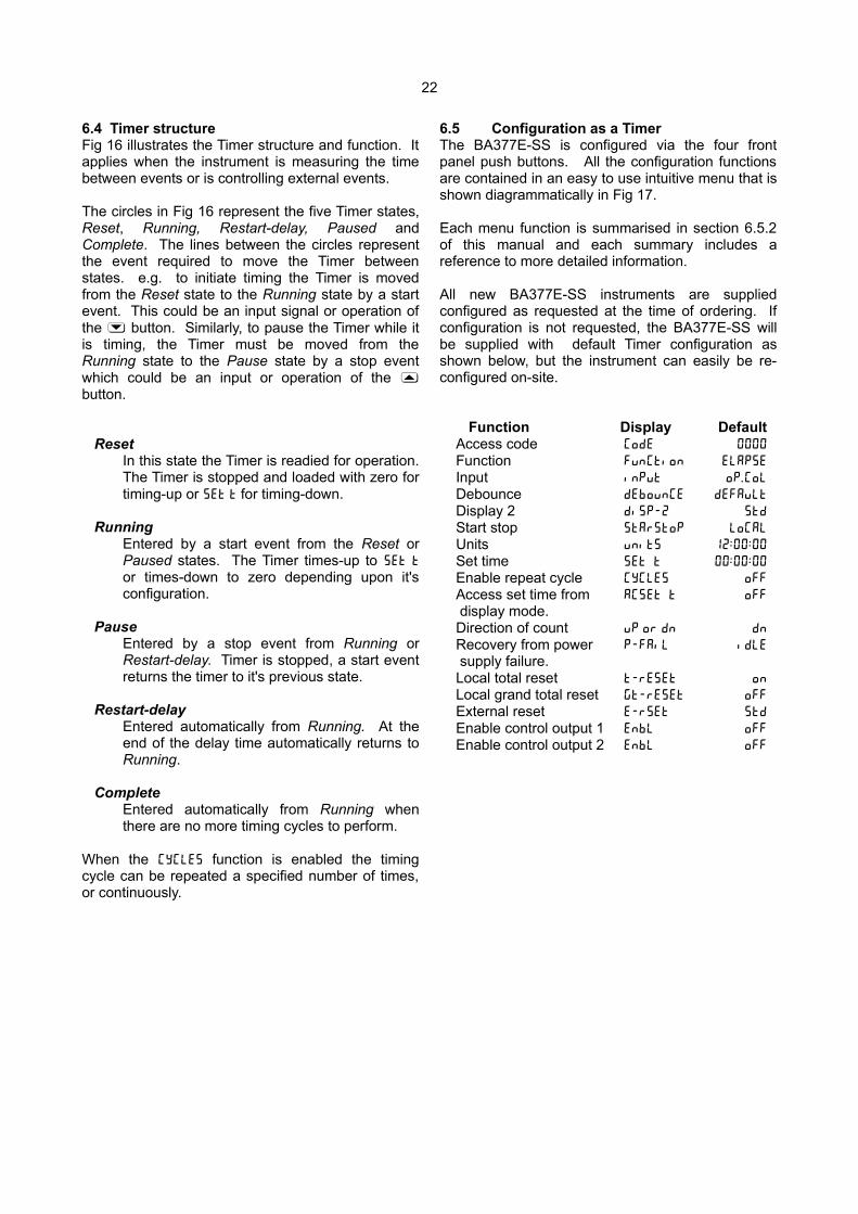
6.4 Timer structureFig 16 illustrates the Timer structure and function. Itapplies when the instrument is measuring the timebetween events or is controlling external events.
The circles in Fig 16 represent the five Timer states,Reset, Running, Restart-delay, Paused andComplete. The lines between the circles representthe event required to move the Timer betweenstates. e.g. to initiate timing the Timer is movedfrom the Reset state to the Running state by a startevent. This could be an input signal or operation ofthe & button. Similarly, to pause the Timer while itis timing, the Timer must be moved from theRunning state to the Pause state by a stop eventwhich could be an input or operation of the *button.
ResetIn this state the Timer is readied for operation.The Timer is stopped and loaded with zero fortiming-up or 5Et t for timing-down.
RunningEntered by a start event from the Reset orPaused states. The Timer times-up to 5et t
or times-down to zero depending upon it'sconfiguration.
PauseEntered by a stop event from Running orRestart-delay. Timer is stopped, a start eventreturns the timer to it's previous state.
Restart-delayEntered automatically from Running. At theend of the delay time automatically returns toRunning.
CompleteEntered automatically from Running whenthere are no more timing cycles to perform.
When the CYCLE5 function is enabled the timingcycle can be repeated a specified number of times,or continuously.
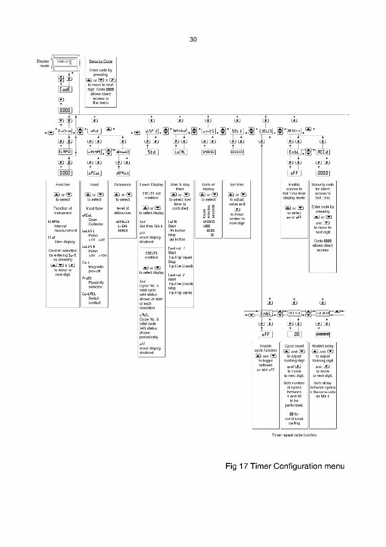
6.5 Configuration as a TimerThe BA377E-SS is configured via the four frontpanel push buttons. All the configuration functionsare contained in an easy to use intuitive menu that isshown diagrammatically in Fig 17.
Each menu function is summarised in section 6.5.2of this manual and each summary includes areference to more detailed information.
All new BA377E-SS instruments are suppliedconfigured as requested at the time of ordering. Ifconfiguration is not requested, the BA377E-SS willbe supplied with default Timer configuration asshown below, but the instrument can easily be re-configured on-site.
Function Display DefaultAccess code CodE 0000
Function FunCtion ELAP5E
Input inPut oP . CoL
Debounce dEbounCE dEFAuLt
Display 2 di5P-2 5td
Start stop 5tAr5toP LoCAL
Units unit5 12 : 00 : 00
Set time 5Et t 00 : 00 : 00
Enable repeat cycle CYCLE5 oFF
Access set time from AC5Et t oFF
display mode.Direction of count uP or dn dn
Recovery from power p-fail idle
supply failure.Local total reset t-rE5Et on
Local grand total reset Gt-rE5Et oFF
External reset E-r5et 5td
Enable control output 1 EnbL oFF
Enable control output 2 EnbL oFF

23
24
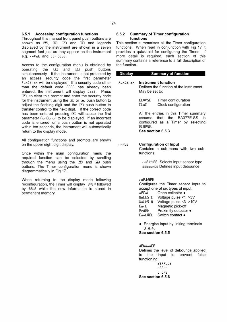
6.5.1 Accessing configuration functionsThroughout this manual front panel push buttons areshown as &, *, ( and ) and legendsdisplayed by the instrument are shown in a sevensegment font just as they appear on the instrumente.g. inPut and Clr Gtot.
Access to the configuration menu is obtained byoperating the ( and ) push buttonssimultaneously. If the instrument is not protected byan access security code the first parameterFunCtion will be displayed. If a security code otherthan the default code 0000 has already beenentered, the instrument will display CodE. Press( to clear this prompt and enter the security codefor the instrument using the & or * push button toadjust the flashing digit and the ( push button totransfer control to the next digit. If the correct codehas been entered pressing ) will cause the firstparameter FunCtion to be displayed. If an incorrectcode is entered, or a push button is not operatedwithin ten seconds, the instrument will automaticallyreturn to the display mode.
All configuration functions and prompts are shownon the upper eight digit display.
Once within the main configuration menu therequired function can be selected by scrollingthrough the menu using the & and * pushbuttons. The Timer configuration menu is showndiagrammatically in Fig 17.
When returning to the display mode followingreconfiguration, the Timer will display dAtA followedby 5AVE while the new information is stored inpermanent memory.
6.5.2 Summary of Timer configuration functions
This section summarises all the Timer configurationfunctions. When read in conjunction with Fig 17 itprovides a quick aid for configuring the Timer. Ifmore detail is required, each section of thissummary contains a reference to a full description ofthe function.
Display Summary of function
FunCtion Instrument functionDefines the function of the instrument.May be set to:
ELAP5E Timer configurationCloC Clock configuration
All the entries in this Timer summaryassume that the BA377E-SS isconfigured as a Timer by selectingELAP5E.See section 6.5.3
inPut Configuration of Input Contains a sub-menu with two sub-functions:
inP . tYPE Selects input sensor typedEbounCE Defines input debounce
inP . tYPE
Configures the Timer sensor input toaccept one of six types of input:oP.CoL Open collector VoLt5 L Voltage pulse <1 >3VVoLt5 H Voltage pulse <3 >10VCoiL Magnetic pick-off Pr.dEt Proximity detector ContACt Switch contact
Energise input by linking terminals 3 & 4.
See section 6.5.5
dEbounCE
Defines the level of debounce appliedto the input to prevent falsefunctioning:
dEFAuLt
HEAVY
LiGHt
See section 6.5.6
25
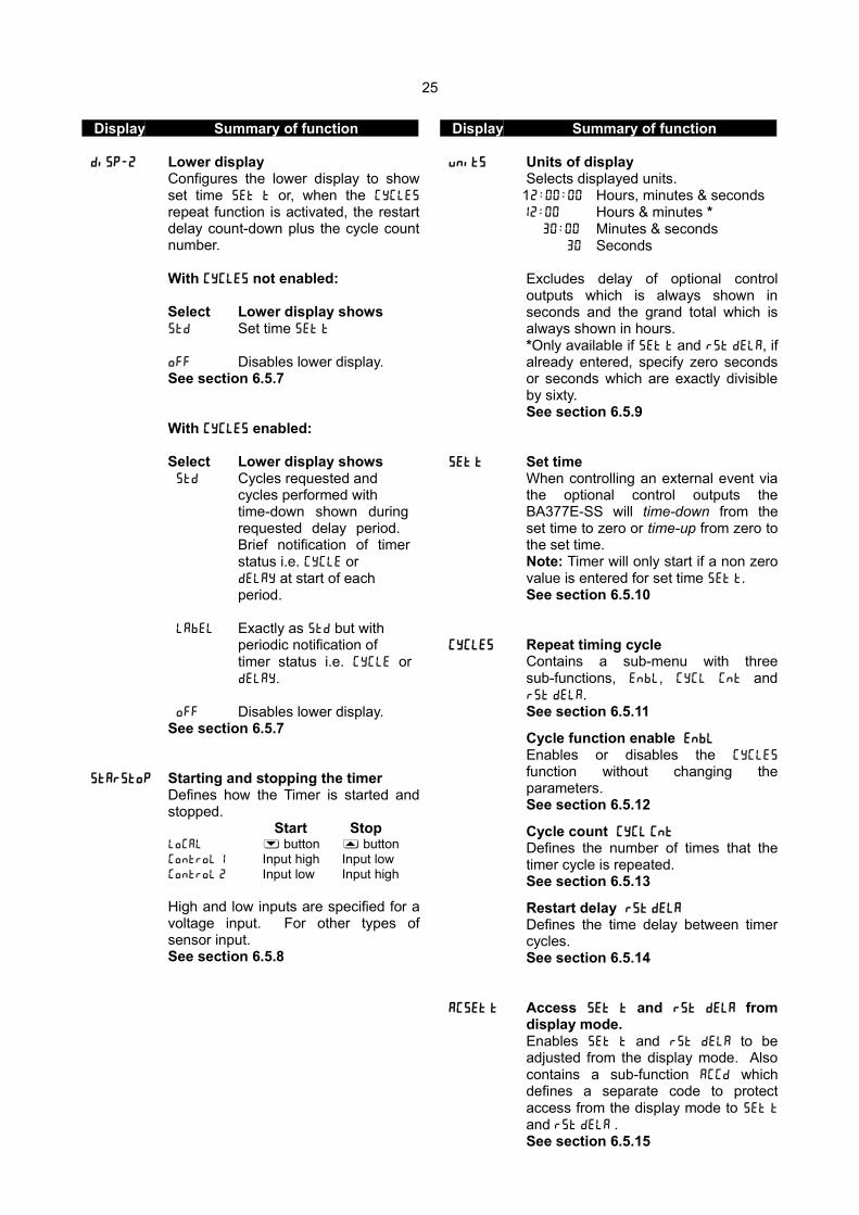
Display Summary of function
di5P-2 Lower displayConfigures the lower display to showset time 5Et t or, when the CYCLE5
repeat function is activated, the restartdelay count-down plus the cycle countnumber.
With CYCLE5 not enabled:
Select Lower display shows5td Set time 5et t
oFF Disables lower display.See section 6.5.7
With CYCLE5 enabled:
Select Lower display shows 5td Cycles requested and
cycles performed with time-down shown during requested delay period. Brief notification of timer status i.e. CYCLE or dELAY at start of each period.
LAbEL Exactly as 5td but with periodic notification of timer status i.e. CYCLE or dELAY.
oFF Disables lower display.See section 6.5.7
5tAr5toP Starting and stopping the timerDefines how the Timer is started andstopped.
Start StopLoCAL & button * buttonControL 1 Input high Input lowControL 2 Input low Input high
High and low inputs are specified for avoltage input. For other types ofsensor input. See section 6.5.8
Display Summary of function
unit5 Units of displaySelects displayed units.
12 : 00 : 00 Hours, minutes & seconds12 : 00 Hours & minutes *
30 : 00 Minutes & seconds 30 Seconds
Excludes delay of optional controloutputs which is always shown inseconds and the grand total which isalways shown in hours.*Only available if 5et t and r5t dELA, ifalready entered, specify zero secondsor seconds which are exactly divisibleby sixty.See section 6.5.9
5Et t Set timeWhen controlling an external event viathe optional control outputs theBA377E-SS will time-down from theset time to zero or time-up from zero tothe set time.Note: Timer will only start if a non zerovalue is entered for set time 5et t.See section 6.5.10
CYCLE5 Repeat timing cycleContains a sub-menu with threesub-functions, EnbL, CYCL Cnt andr5t dELA.See section 6.5.11
Cycle function enable EnbL
Enables or disables the cycle5
function without changing theparameters.See section 6.5.12
Cycle count CYCL Cnt
Defines the number of times that thetimer cycle is repeated.See section 6.5.13
Restart delay r5t dELA
Defines the time delay between timercycles.See section 6.5.14
AC5Et t Access 5Et t and r5t dela fromdisplay mode.Enables 5Et t and r5t dela to beadjusted from the display mode. Alsocontains a sub-function ACCd whichdefines a separate code to protectaccess from the display mode to 5Et t
and r5t dela .See section 6.5.15
26
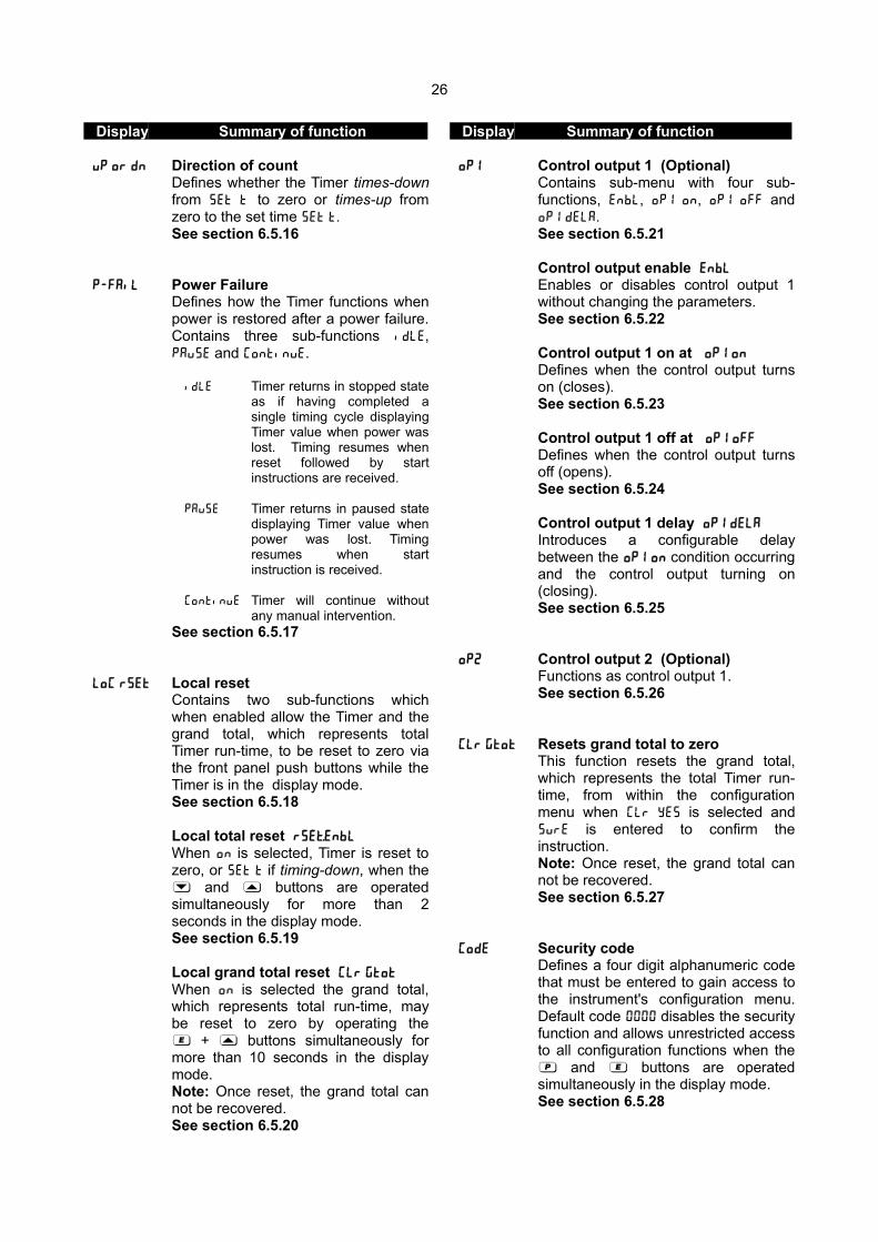
Display Summary of function
uP or dn Direction of countDefines whether the Timer times-downfrom 5Et t' to zero or times-up fromzero to the set time 5Et t.See section 6.5.16
P-FAiL Power FailureDefines how the Timer functions whenpower is restored after a power failure.Contains three sub-functions idle,Pau5E and continue.
idle Timer returns in stopped stateas if having completed asingle timing cycle displayingTimer value when power waslost. Timing resumes whenreset followed by startinstructions are received.
Pau5e Timer returns in paused statedisplaying Timer value whenpower was lost. Timingresumes when startinstruction is received.
Continue Timer will continue withoutany manual intervention.
See section 6.5.17
LoC r5Et Local resetContains two sub-functions whichwhen enabled allow the Timer and thegrand total, which represents totalTimer run-time, to be reset to zero viathe front panel push buttons while theTimer is in the display mode.See section 6.5.18
Local total reset r5Et.EnbL
When on is selected, Timer is reset tozero, or 5et t if timing-down, when the& and * buttons are operatedsimultaneously for more than 2seconds in the display mode.See section 6.5.19
Local grand total reset CLr Gtot
When on is selected the grand total,which represents total run-time, maybe reset to zero by operating the) + * buttons simultaneously formore than 10 seconds in the displaymode.Note: Once reset, the grand total cannot be recovered.See section 6.5.20
Display Summary of function
oP1 Control output 1 (Optional)Contains sub-menu with four sub-functions, EnbL, oP1 on, oP1 oFF andoP1 dELA.See section 6.5.21
Control output enable EnbL
Enables or disables control output 1without changing the parameters.See section 6.5.22
Control output 1 on at oP1 on
Defines when the control output turnson (closes).See section 6.5.23
Control output 1 off at oP1 oFF
Defines when the control output turnsoff (opens).See section 6.5.24
Control output 1 delay oP1 dELA
Introduces a configurable delaybetween the oP1 on condition occurringand the control output turning on(closing).See section 6.5.25
oP2 Control output 2 (Optional)Functions as control output 1.See section 6.5.26
CLr Gtot Resets grand total to zeroThis function resets the grand total,which represents the total Timer run-time, from within the configurationmenu when CLr YE5 is selected and5urE is entered to confirm theinstruction.Note: Once reset, the grand total cannot be recovered.See section 6.5.27
CodE Security codeDefines a four digit alphanumeric codethat must be entered to gain access tothe instrument's configuration menu.Default code 0000 disables the securityfunction and allows unrestricted accessto all configuration functions when the( and ) buttons are operatedsimultaneously in the display mode.See section 6.5.28
27
Display Summary of function
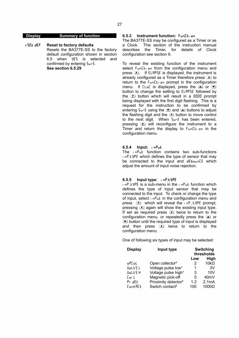
r5Et dEF Reset to factory defaultsResets the BA377E-SS to the factorydefault configuration shown in section6.5 when YE5 is selected andconfirmed by entering 5urE.See section 6.5.29
6.5.3 Instrument function: FunCtion
The BA377E-SS may be configured as a Timer or asa Clock. This section of the instruction manualdescribes the Timer, for details of Clockconfiguration see section 9.
To reveal the existing function of the instrumentselect FunCtion from the configuration menu andpress (. If ELAP5E is displayed, the instrument isalready configured as a Timer therefore press ) toreturn to the FunCtion prompt in the configurationmenu. If CloC is displayed, press the * or &button to change the setting to ELAP5E followed bythe ( button which will result in a 0000 promptbeing displayed with the first digit flashing. This is arequest for the instruction to be confirmed byentering 5urE using the & and * buttons to adjustthe flashing digit and the ( button to move controlto the next digit. When 5urE has been entered,pressing ) will reconfigure the instrument to aTimer and return the display to FunCtion in theconfiguration menu.
6.5.4 Input: inPut
The inPut function contains two sub-functionsinP . tYPE which defines the type of sensor that maybe connected to the input and dEbounCE whichadjust the amount of input noise rejection.
6.5.5 Input type: inP . tYPE
inP . tYPE is a sub-menu in the inPut function whichdefines the type of input sensor that may beconnected to the input. To check or change the typeof input, select inPut in the configuration menu andpress ( which will reveal the inP . tYPE prompt,pressing ( again will show the existing input type.If set as required press ) twice to return to theconfiguration menu, or repeatedly press the * or& button until the required type of input is displayedand then press ) twice to return to theconfiguration menu.
One of following six types of input may be selected:
Display Input type Switchingthresholds
Low HighoPCoL Open collector² 2 10kΩVoLt5 L Voltage pulse low¹ 1 3VVoLt5 H Voltage pulse high¹ 3 10VCoiL Magnetic pick-off 0 40mVPr . dEt Proximity detector² 1.2 2.1mAContACt Switch contact² 100 1000Ω

28
Notes:1. Maximum voltage input +28V.
2. For sensors that require energising i.e.proximity detectors, switch contacts andthose with open collector outputs, terminals3 & 4 of the BA377E-SS Timer should belinked together.
3. For the Timer to function correctly, the inputsignal must fall below the lower switchingthreshold and rise above the higherswitching threshold for the times shown inthe debounce section 6.5.6 below.
6.5.6 debounce: dEbouncE
dEbouncE is an adjustable sub-menu in the inPut
function which prevents the Timer malfunctioningwhen the input has noisy edges, such as thoseresulting from a mechanical contact closing andbouncing. Three levels of protection may beselected and the amount of debounce applieddepends upon the type of Timer input that has beenselected in the inP . tYPE function.
The following table shows the minimum time that theinput signal must be continuously above the upperinput switching threshold and continuously below thelower switching threshold to ensure that the Timerprocesses the input signal. Input switchingthresholds are shown in section 6.5.5.
Debouncelevel
Min input pulse width
Type of Input
Contact All others
Default 1600µs 40µs
Heavy 3200µs 350µs
Light 400µs 5µs
6.5.7 Lower display: di5P-2
The configuration of the lower display which has six12mm high digits, depend upon whether the repeattimer function CYCLE5, which can repeat the timingperiod up to 99 times or continuously with aconfigurable delay between periods, is enabled. Theconfiguration options are:
CYCLE5 disabledThe lower display shows the set time 5ET t
or the lower display may be disabled.
CYCLE5 enabledThe lower display shows the total number ofrepeat cycles requested together with thecurrent cycle number. During theconfigurable delay between cycles thedisplay times-down from the requesteddelay time to zero. Each operation may bebriefly named at it's start or periodicallythroughout the cycle.The lower display may also be disabled ifnot required.
To check or change the configuration of the lowerdisplay select di5P-2 from the configuration menuand press ( which will reveal the existing settingwhich can be changed by pressing the * or &button followed by the ) button to enter theselection and return to the configuration menu.
If the CYCLE5 function is not enabled thefollowing two options are available:
5td Lower display shows the Timer's settime 5Et t, from which the BA377E-SSwill time-up or time-down dependingupon the direction of count selected inthe uP or dn function.
oFF Lower display disabled.

29
If the CYCLE5 function is enabled the followingthree options are available:
5td Lower display shows the number ofcycles requested together with thecurrent cycle number. During theconfigurable delay period the displaytimes-down from the requested delay tozero. A brief notification of timer statusi.e. CYCLE or dELAY is shown at start ofeach period.
02 - 11Current Number of cyclescycle requested, not shown
number shown when cycle is continuously repeated.
LabEL Exactly the same as 5td, but timerstatus i.e. CYCLE or dELAY is shownperiodically.
oFF Lower display disabled.
6.5.8 Starting & stopping the Timer: 5tAr5toP
The Timer may be started and stopped by a sensorinput signal or by operation of the front panel * or& push buttons. To check or change the control ofthe Timer, select 5tAr5toP from the configurationmenu and press ( which will reveal the existingsetting which can be changed by pressing the * or& button followed by the ) button to enter theselection and return to the configuration menu.Options available are:
Voltage inputs or control from front panelDisplay Start Stop
ControL 1 Input high Input lowControL 2 Input low Input highLoCAL & button * button
Contact and open collector inputsDisplay Start Stop
ControL 1 Open ClosedControL 2 Closed Open
Proximity detector inputDisplay Start Stop
ControL 1 Low current High currentControL 2 High current Low current
6.5.9 Units of display: unit5
Defines the format of all displayed times, except thedelay time of the optional control outputs which isshown in seconds and the grand total which isshown in hours and tenths of an hour.
To check or change the units of display, select unit5
from the configuration menu and press ( whichwill reveal the existing setting. The required unitscan be selected by pressing the * or & buttonfollowed by the ) button to enter the selection andreturn to the configuration menu. The optionsavailable are shown below:
Display12 : 00 : 00 Hours, minutes & seconds12 : 00 Hours & minutes* 30 : 00 Minutes & seconds 30 Seconds
* Only available when time in seconds specified inany Timer function is zero or divisible by 60.
The Timer's maximum elapsed time in any format isequivalent to 99 hours, 59 minutes & 59 seconds.
30

31
32
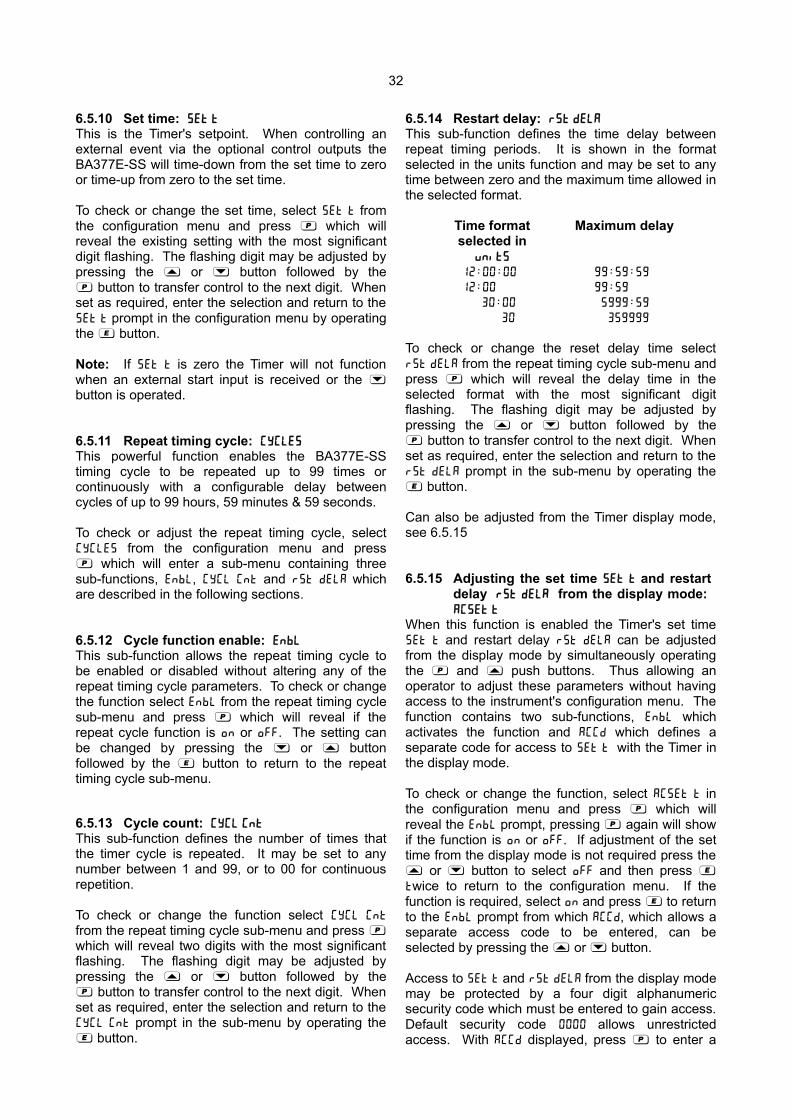
6.5.10 Set time: 5Et t
This is the Timer's setpoint. When controlling anexternal event via the optional control outputs theBA377E-SS will time-down from the set time to zeroor time-up from zero to the set time.
To check or change the set time, select 5Et t fromthe configuration menu and press ( which willreveal the existing setting with the most significantdigit flashing. The flashing digit may be adjusted bypressing the * or & button followed by the( button to transfer control to the next digit. Whenset as required, enter the selection and return to the5Et t prompt in the configuration menu by operatingthe ) button.
Note: If 5Et t is zero the Timer will not functionwhen an external start input is received or the &button is operated.
6.5.11 Repeat timing cycle: CYCLE5
This powerful function enables the BA377E-SStiming cycle to be repeated up to 99 times orcontinuously with a configurable delay betweencycles of up to 99 hours, 59 minutes & 59 seconds.
To check or adjust the repeat timing cycle, selectcycle5 from the configuration menu and press( which will enter a sub-menu containing threesub-functions, EnbL, CYCL Cnt and r5t dELA whichare described in the following sections.
6.5.12 Cycle function enable: EnbL
This sub-function allows the repeat timing cycle tobe enabled or disabled without altering any of therepeat timing cycle parameters. To check or changethe function select EnbL from the repeat timing cyclesub-menu and press ( which will reveal if therepeat cycle function is on or oFF. The setting canbe changed by pressing the & or * buttonfollowed by the ) button to return to the repeattiming cycle sub-menu.
6.5.13 Cycle count: cycl cnt
This sub-function defines the number of times thatthe timer cycle is repeated. It may be set to anynumber between 1 and 99, or to 00 for continuousrepetition.
To check or change the function select cycl cnt
from the repeat timing cycle sub-menu and press (which will reveal two digits with the most significantflashing. The flashing digit may be adjusted bypressing the * or & button followed by the( button to transfer control to the next digit. Whenset as required, enter the selection and return to thecycl cnt prompt in the sub-menu by operating the) button.
6.5.14 Restart delay: r5t dela
This sub-function defines the time delay betweenrepeat timing periods. It is shown in the formatselected in the units function and may be set to anytime between zero and the maximum time allowed inthe selected format.
Time format Maximum delayselected in
unit5
12 : 00 : 00 99 : 59 : 59
12 : 00 99 : 59
30 : 00 5999 : 59
30 359999
To check or change the reset delay time selectr5t dela from the repeat timing cycle sub-menu andpress ( which will reveal the delay time in theselected format with the most significant digitflashing. The flashing digit may be adjusted bypressing the * or & button followed by the( button to transfer control to the next digit. Whenset as required, enter the selection and return to ther5t dela prompt in the sub-menu by operating the) button.
Can also be adjusted from the Timer display mode,see 6.5.15
6.5.15 Adjusting the set time 5Et t and restart delay r5t dela from the display mode: AC5Et t
When this function is enabled the Timer's set time5Et t and restart delay r5t dela can be adjustedfrom the display mode by simultaneously operatingthe ( and * push buttons. Thus allowing anoperator to adjust these parameters without havingaccess to the instrument's configuration menu. Thefunction contains two sub-functions, EnbL whichactivates the function and ACCd which defines aseparate code for access to 5Et t with the Timer inthe display mode.
To check or change the function, select AC5Et t inthe configuration menu and press ( which willreveal the EnbL prompt, pressing ( again will showif the function is on or oFF. If adjustment of the settime from the display mode is not required press the* or & button to select off and then press )twice to return to the configuration menu. If thefunction is required, select on and press ) to returnto the EnbL prompt from which ACCd, which allows aseparate access code to be entered, can beselected by pressing the * or & button.
Access to 5Et t and r5t dela from the display modemay be protected by a four digit alphanumericsecurity code which must be entered to gain access.Default security code 0000 allows unrestrictedaccess. With ACCd displayed, press ( to enter a
33
new access code. The Timer will display 0000 withone digit flashing. The flashing digit may beadjusted using the * or & push button, when setas required operating the ( button will transfercontrol to the next digit. When all the digits havebeen entered press ) twice to return to the AC5Et t
prompt in the configuration menu. The revisedaccess code will be activated when the BA377E-SSis returned to the display mode.
Please contact BEKA associates sales department ifthe access code is lost.
6.5.16 Direction of count: uP or dn
The Timer may be configured to time-up from zero tothe set time 5Et t while displaying elapsed time, orto time-down from the set time 5Et t to zero whiledisplaying the remaining time.
When the repeat timing cycle function CYCLE5 isenabled, it is recommended that a down count isselected so that the progress of the timer can beobserved with a known completion time i.e zero. Ifset as an up counter, elapsed will be displayed, but5et t at which the Timer will stop is not shown.
To check the direction of count, select uP or dn fromthe configuration menu and press ( which willreveal the existing setting which can be changed bypressing the * or & button followed by the )button to enter the selection and return to theconfiguration menu.
6.5.17 Power Fail: P-FAiL
Defines how the Timer powers-up and functionswhen power is restored after a power supplyinterruption. Three options are available, idle,Pau5e and continue.
idle The Timer is stopped in the state it achieveswhen it has timed-up to 5et t or timed-downto 0000,,with the elapsed or remaining timewhen power was lost shown on the upperdisplay. The Timer must be reset before itcan be restarted. If the repeat timing cycleis in use the number of cycles completedwill be lost when the Timer is reset.
Pau5e The Timer is stopped in the state it achievesfollowing receipt of a stop input to pausetiming. The elapsed or remaining time whenpower was lost is shown on the upperdisplay. Timing resumes when a startinstruction is received. If a start input existswhen power is restored timing will startimmediately.
Continue When power is restored the Timer willcontinue from where it stopped without anymanual intervention. To check or changethe function, select P-fail from theconfiguration menu and press ( which willreveal the existing setting which can bechanged by pressing the * or & buttonfollowed by the ) button to enter theselection and return to the configurationmenu.
6.5.18 Local reset: LoC r5Et
The Local reset function contains two separate sub-functions rE5Et . enbl and clr Gtot which whenenabled allow the Timer and the grand total to bereset via the instrument's front panel push buttonswhile the Timer is in the display mode.
6.5.19 Local total reset: r5Et . enbl
rE5Et.enbl is a sub-function in the Loc r5Et functionwhich when activated allows an operator to reset theTimer from the display mode by operating the *and & push buttons simultaneously for more thanthree seconds.
To check or change the local total reset selectLoC r5Et in the configuration menu and press( which will reveal the LoC r5Et prompt, press( again to show if the local total reset is on or oFF.If set as required operate the ) button twice toreturn to the configuration menu, or the * or &button to change the setting followed by the )button twice to enter the change and return to theLoC . r5Et prompt in the configuration menu.
Note:The Timer may also be reset remotely byconnecting terminals RS1 and RS2 togetherfor more than one second. See section 3.1.8or 3.2.8
6.5.20 Local grand total reset: Clr Gtot
The grand total is the total run-time of the Timer thatmay be viewed by operating the ) and * pushbuttons simultaneously in the display mode. Whenactivated clr Gtot allows an operator to reset thegrand total display to zero from the display mode byoperating the ) and * push buttonssimultaneously for more than ten seconds.
Clr Gtot is a sub-function in the LoC r5Et menu. Tocheck or change the setting select LoC r5Et in theconfiguration menu and press ( which will revealrE5Et . enbl. Using the & or * button selectClr Gtot and press ( which will show if local grandtotal reset is on or oFF. If set as required operatethe ) button twice to return to the configurationmenu, or the & or * button to change the settingfollowed by the ) button twice to enter the changeand return to the LoC r5Et prompt in theconfiguration menu.
34
6.5.21 Control output 1 (optional): op1
Control output 1 is an optional factory fitted,galvanically isolated solid state switch contact whichcan be configured to turn on or off when the Timeris in any of it's five states. The control output statusis shown by the 1 control output display annunciator.
The function contains four sub-functions, EnbL,op1 on, op1 oFF and op1 dELA. To gain access to thesub-menu select op1 in the configuration menu andpress ( which will show the EnbL prompt fromwhich the other sub-functions can be accessedusing the & or * button.
There are ten independent Control Output 1 on andoff conditions. If Control Output 1 is only required tobe active in one Timer state configure as follows:
op1 on state required e.g. run
op1 off n state required e.g. n run
If Control Output 1 is required to be active in allTimer states except one, configure as follows:
5tat on n state required e.g. n run
5tat off state required e.g. run
Control Output 1 can also be configured to be activein three Timer states. e.g. when configured asshown below Control Output 1 is on in the pau5ed,delay and done states, but off in the other two Timerstates.
5tat on n run
5tat off re5et
6.5.22 Control output 1 enable: EnbL
This function allows control output 1 to be enabledor disabled without altering any other control outputparameters. To check or change the function selectEnbL from the control output 1 sub-menu and press( to reveal if control output 1 is on or oFF. Thesetting can be changed by pressing the & or *button followed by the ) button to return to thecontrol output 1 sub-menu.
6.5.23 Control output 1 on at: op1 on
Control output 1 is very versatile and may beconfigured to turn on (output closed) in any one ofthe five Timer states, or to turn on when the Timer isnot in one of the Timer states. Timer states areshown in Fig 16.
To define when output 1 is on select op1 on from thecontrol output 1 sub-menu and press ( to show theexisting setting. Pressing the & or * button willscroll through the options:
Display Output 1 on when Timer is in
re5et Reset state run Run statepau5e Pause statedelay Delay statedone Complete state
Output 1 on when Timer is NOT in
n re5et Reset state n run Run staten pau5e Pause staten delay Delay staten done Complete state
When the required setting has been selected press) to enter the selection and return to the controloutput 1 sub-menu.
6.5.24 Control output 1 off at: op1 off
Control output 1 may be configured to turn off(output open) in any one of the five Timer states, orto turn off when the timer is not in one of the fiveTimer states. Timer states are shown in Fig 16.
To define when the output 1 is off select op1 off
from the sub-menu and press ( to show theexisting setting. Pressing the & or * button willscroll through the options:
Display Output 1 off when Timer is in
re5et Reset state run Run statepau5e Pause statedelay Delay statedone Complete state
Output 1 off when Timer is NOT inn re5et Reset state n run Run staten pau5e Pause staten delay Delay staten done Complete state
When the required setting has been selected press) to enter the selection and return to the controloutput 1 sub-menu.

35
6.5.25 Control output 1 on delay time: op1 dELA
Control output 1 may be delayed from turning on
(output closed) for a fixed time following the selectedcondition occurring. e.g. when the Timer enters theRun state. This delay can be adjusted in 1 secondincrements up to 32,400 seconds, which is 9 hours.If a delay is not required zero should be entered. Toadjust the delay select op1 dELA from the controloutput 1 sub-menu and press ( which will revealthe existing delay time with one digit flashing. Theflashing digit can be adjusted using the & or *button and the ( button to move to the next digit.When the required delay has been entered, press) to return to the control output 1 sub-menu.
Timer configuration examples in section 7.2. and 7.3of this manual illustrate how to configure the optionalcontrol outputs.
6.5.26 Control output 2 (optional): op2
Control output 2 is an optional, galvanically isolatedsolid state switch contact which can beindependently configured to turn on and off when theTimer is any of it's five states. It's functions andconfiguration are identical to control output 1described in sections 6.5.21 to 6.5.25
The control output status is shown by the 2 controloutput display annunciator.
6.5.27 Reset grand total from within the configuration menu: Clr Gtot
The grand total is the total run-time of the Timer thatmay be viewed by operating the ) and * pushbuttons simultaneously in the display mode.
The grand total can be reset to zero from within theconfiguration menu using this Clr Gtot function, orfrom the display mode if Clr Gtot is activated in thelocal grand total clear function - see 6.5.20
To zero the Timer grand total from within theconfiguration menu select Clr Gtot and press( which will cause the instrument to display Clr . no
with no flashing. Press the & or * push buttonuntil Clr . YE5 is displayed and then press ( whichwill result in a 0000 prompt being displayed with thefirst digit flashing. This is a request for theinstruction to be confirmed by entering 5urE usingthe & and * buttons to adjust the flashing digitand the ( button to move control to the next digit.Pressing ) will then reset the grand total to zeroand return the Timer to the configuration menu.
Note: Once reset, the grand total can not be recovered.
6.5.28 Security code: CodEAccess to the instrument configuration menu may beprotected by a four digit alphanumeric security codewhich must be entered to gain access. Newinstruments are configured with the default securitycode 0000 which allows unrestricted access to allconfiguration functions.
To enter a new security code select CodE from theconfiguration menu and press ( which will causethe Timer to display 0000 with one digit flashing.The flashing digit may be adjusted using the * and& push button, when set as required operating the( button will transfer control to the next digit.When the new security code has been entered press) to return to the CodE prompt. The revised securitycode will be activated when the Timer is returned tothe display mode.
Please contact BEKA associates sales department ifthe security code is lost.
6.5.29 Reset configuration to Timer factory defaults: r5Et dEF
When the BA377E-SS is configured as a Timer thisfunction resets the instrument to the Timer factorydefaults shown in sections 6.5
To reset the configuration select r5Et dEF from theconfiguration menu and press (. The BA377E-SSwill display 0000 with the first digit flashing which is arequest to confirm the instruction by entering 5urE.Using the * or & button set the first flashing digitto 5 and press ( to transfer control to the seconddigit which should be set to u. When 5urE has beenentered pressing the ) button will reset all theconfiguration functions and return the instrument tothe display mode.
Note:r5Et dEF does not reset the grand total to zero.

36
7. TIMER APPLICATION EXAMPLESThis section illustrates two common applications forthe BA377E-SS when configured as a Timer.
7.1 Measuring the time that a contact is closed.
In this example a BA377E-SS is required to displaythe time that a hazardous area contact is closed.The display is required in hours and minutes withinthe hazardous area and is to be reset to zero by apush button located in the same hazardous area, notby the instrument front panel push buttons. Theoperator is required to zero the grand total byoperating the ) and * buttons simultaneously.No security codes are required to protect access tothe configuration menu or to the grand total reset.When power is restored after a supply interruptionthe Timer is to resume normal operation withoutmanual intervention.
Figure 18 shows the wiring for the BA377E-SS whenpowered by a single channel Zener barrier.
Fig 18 Wiring for displaying time a contact is closed
The required instrument configurations for thisexample are shown below.
Function Display SettingAccess code CodE 0000
Function FunCtion ELAP5E
Input inPut ContACt
Terminals 3 & 4 linked to energise input
debounce dEbounCE dEFAuLt
Display 2 di5P-2 oFF
Start stop 5tAr5toP ControL 2
Units unit5 12 : 00
Set time 5Et t 9999 : 99 : 99
Direction of count up or dn up
Power fail p-fail continue
Local reset loc r5et
Local total reset rE5E EnbL oFF
Local grand total reset Clr Gtot on
7.2 Controlling an IS solenoid valveThe BA377E-SS Timer is required to open anintrinsically safe solenoid valve for 5 minutes whenan external contact is closed. 55 minutes after thevalve is closed it is to be opened again for another 5minute period. This process is to be repeated 10times after which the Timer is to automatically resetso that is ready to start the next 10 cycles when theexternal contact is closed.
In this example which is shown in Fig 19, controloutput 2 has been wired to the timer reset terminalsand configured with a five seconds control outputdelay after the solenoid valve has closed for thetenth time. Therefore five seconds after the tenthcycle has been completed the system automaticallyresets and is ready for the next timing cycle to beinitiated.
The lower display is required to show timer status atthe start of each period.
After a power interruption the timer is required toresume operation from the point at which it stoppedwhen the start button is operated.
Fig 19 Control of valve in a hazardous area

37
The required instrument configuration for thisexample are shown below.
Function Display SettingAccess code CodE 0000
Function FunCtion ELAP5E
Input input
Input inP . type ContACt
Terminals 3 & 4 linked to energise input
debounce dEbounCE dEFAuLt
Display 2 di5P-2 5td
Start stop 5tAr5toP ControL 2
Units unit5 12 : 00
Set time 5Et t 00 : 05
Timer repeat cycle CYCLE5
Cycle function enable EnbL on
Cycle count cycl cnt 10
Reset delay r5t dela 00 : 55
Access set time from AC5Et - t oFF
display mode.
Direction of count uP or dn uP
Power failure p-fail pau5e
Local reset loc r5et
Local total reset r5Et . EnbL oFF
Local grand total reset CLr Gtot oFF
Output 1 op 1
Enable control output 1 EnbL on
Control output 1 on at oP1 on run
Control output 1 off at oP1 oFF n run
Control output 1 delay oP1 dELA 00000
Output 2 op 2
Enable control output 2 EnbL on
Control output 2 on at oP2 on done
Control output 2 off at oP2 oFF re5et
Control output 2 delay oP2 dELA 00005
7.3 Cycling an IS solenoid valveIn this example which is shown in Fig 20, aBA377E-SS is required to cycle an intrinsically safesolenoid valve such that it opens 4 times for 10minutes at 15 minutes intervals. Once all 4 solenoidvalve cycles have been completed a remote“Sequence Complete” lamp is illuminated in the safearea until the reset push button is operated.
If, during the sequence, power is lost the controloutputs are to remain de-engergised when power isrestored. The timer is to recommence operatingfrom the last known point when the start push buttonis pressed.
For this application the BA377E-SS Timer requiresdual control outputs which are a factory fitted optionand should be specified when the instrument isordered.
When the start button is closed output 1 closeswhich opens the solenoid valve and the countertimes-down 10 minutes. When the elapsed timeequals zero, output 1 opens thus closing thesolenoid valve. The timer then counts down the 15minute delay which is shown on the lower display(display 2). When the delay equals zero, output 1closes again for a second 10 minutes, the wholecycle being repeated such that the solenoid valveopens and closes 4 times. After the solenoid valvehas closed for a fourth time output 2 closes whichilluminates a “Sequence Complete” lamp indicatingthat the whole operation is finished.
The lamp remains illuminated until the reset pushbutton is closed for 2 seconds (Reset is shown onthe display) at which point control output 2 is de-energised which turns the lamp off.
Note:Both the timer (display 1) and delay (display 2) willcount down - but the cycle display counts uptowards its target.

38
Fig 20 Control of valve in a hazardous area.
The required instrument configuration for this example is shown below:
Function Display SettingFunction FunCtion ELAP5E
Input A inPut-A ContACt
Debounce (both inputs) dEbounCE dEFAuLt
Display 2 di5P-2 5td
Start stop 5tAr5toP ControL 2
Units unitS 12 : 00 : 00
Set time 5Et t 00 :10 : 00
Timer repeat cycle CYCLE5
Enable Repeat Cycle EnbL on
Cycle Count CYCL Cnt 04
Reset delay r5t dELA 00 :15 : 00
Access set time fromdisplay mode. AC5Et-t oFF
Direction of count uP or dn dn
Control output afterpower restoration P-FAiL PAu5E
Local total reset LoC r5Et oFF
External Reset ContactClosure Time E r5Et 5td
Status Output 5tAt oP dEFAuLt
Output 1 oP1
Enable control output 1 EnbL on
Control output 1 on at oP1 on run
Control output 1 off at oP 1 oFF n run
Control output 1 delay oP1 dELA 00000
Output 2 oP2
Enable control output 2 EnbL on
Control output 2 on at oP2 on donE
Control output 2 off at oP2 oFF rE5ET
Control output 2 delay oP2 dELA 00000
Local grand total reset CLr Gtot oFF
Access code CodE dEFAuLt
Note: Functions in bold are first level menu items.

39
8. MAINTENANCE when configured as a Timer
8.1 Fault finding during commissioningIf a BA377E-SS fails to function as a Timer duringcommissioning the following procedure should befollowed:
Symptom Cause Check:
No display No powersupply, or
incorrect wiring.Note: Terminals2, 6 & RS2 areinterconnected
within theinstrument.
That there isbetween 10 and
28V onterminals 1 & 2with terminal 1
positive.
Instrumentconfiguration
menu does notcorrespond withTimer section of
this manual.
BA377E-SS maybe configured as
a clock.
That FunCtion in configurationmenu is set toELAP5E not to
CloC.
Timer will notstart.
Timer not reset
Set time 5Et t
has not beenentered.
Reset timer viaexternal contactor by operating
* and &buttons
simultaneously ifthe local total
reset r5Et enbL
has beenactivated.
Enter a value for5Et t' other than
zero.
Timer will notrespond to
external input.
Input incorrectlyconfigured, or
sensorincorrectlyconnected.
Inputconfiguration
and inputenergising link is
correctly fittedfor selected
sensor.
Control output(s)do not function.
Control outputshave not been
enabled.
Enable ControlOutput(s) in the
configurationmenu.
Unable to enterconfiguration
menu.
Incorrect securitycode
That the correctsecurity code is
being used.
Contact BEKA ifcode is lost.
8.2 Fault finding after commissioning
ENSURE PLANT SAFETY BEFORESTARTING MAINTENANCE
Live maintenance is permitted onintrinsically safe equipment installed ina hazardous area, but only certified testequipment should be used unless a gasclearance certificate is available.
If a BA377E-SS fails after it has been functioningcorrectly, the following table may help to identify thecause of the failure.
Symptom Cause Check:
No display No power supply That there isbetween 10 and
28V onterminals 1 & 2with terminal 1
positive.
Timer will notstart.
Timer not reset
Reset terminalsRS1 & RS2 arelinked which will
inhibit Timer.
Reset timer viaexternal contactor by operating
* and &buttons
simultaneously iflocal total resetrE5Et . EnbL hasbeen activated.
Remove link.
Control output(s)do not function.
Control Outputshave not been
enabled.
Enable ControlOutput(s) in the
configurationmenu.
Unable to enterconfiguration
menu.
Incorrect securitycode
That the correctsecurity code is
being used.Contact BEKA if
code is lost.
If this procedure does not reveal the cause of thefault, it is recommended that the instrument isreplaced.
Note:If configuration changes are made to Input,5tart5top, cycle5, up or dn, op1 or op2
functions the Timer will be forced into a failsafe idle condition. This stops the Timer inthe state it achieves when it has timed-up to5et t or timed-down to 0000. The Timermust be reset before it can be restarted.

40
8.3 ServicingWe recommend that faulty BA377E-SS Timers arereturned to BEKA associates or to our local agent forrepair. It is helpful if a brief description of the faultsymptoms is provided.
8.4 Routine maintenanceThe mechanical and electrical condition of theinstrument should be regularly checked. Inspectionfrequency should be chosen to suit theenvironmental conditions.
8.5 GuaranteeInstruments which fail within the guarantee periodshould be returned to BEKA associates or our localagent. It is helpful if a brief description of the faultsymptoms is provided.
8.6 Customer commentsBEKA is always pleased to receive comments fromcustomers about our products and services. Allcommunications are acknowledged and wheneverpossible, suggestions are implemented.
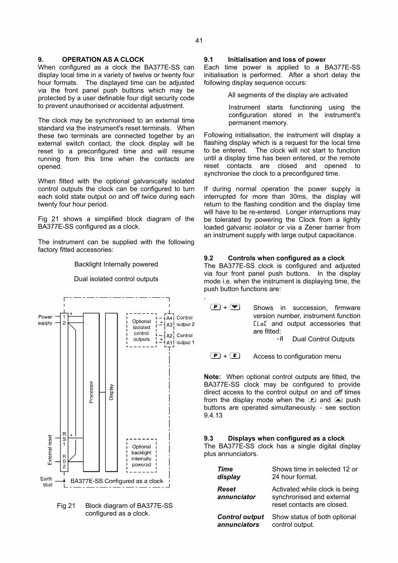
41
9. OPERATION AS A CLOCKWhen configured as a clock the BA377E-SS candisplay local time in a variety of twelve or twenty fourhour formats. The displayed time can be adjustedvia the front panel push buttons which may beprotected by a user definable four digit security codeto prevent unauthorised or accidental adjustment.
The clock may be synchronised to an external timestandard via the instrument's reset terminals. Whenthese two terminals are connected together by anexternal switch contact, the clock display will bereset to a preconfigured time and will resumerunning from this time when the contacts areopened.
When fitted with the optional galvanically isolatedcontrol outputs the clock can be configured to turneach solid state output on and off twice during eachtwenty four hour period.
Fig 21 shows a simplified block diagram of theBA377E-SS configured as a clock.
The instrument can be supplied with the followingfactory fitted accessories:
Backlight Internally powered
Dual isolated control outputs
Fig 21 Block diagram of BA377E-SS configured as a clock.
9.1 Initialisation and loss of powerEach time power is applied to a BA377E-SSinitialisation is performed. After a short delay thefollowing display sequence occurs:
All segments of the display are activated
Instrument starts functioning using theconfiguration stored in the instrument'spermanent memory.
Following initialisation, the instrument will display aflashing display which is a request for the local timeto be entered. The clock will not start to functionuntil a display time has been entered, or the remotereset contacts are closed and opened tosynchronise the clock to a preconfigured time.
If during normal operation the power supply isinterrupted for more than 30ms, the display willreturn to the flashing condition and the display timewill have to be re-entered. Longer interruptions maybe tolerated by powering the Clock from a lightlyloaded galvanic isolator or via a Zener barrier froman instrument supply with large output capacitance.
9.2 Controls when configured as a clock The BA377E-SS clock is configured and adjustedvia four front panel push buttons. In the displaymode i.e. when the instrument is displaying time, thepush button functions are:
*
( + & Shows in succession, firmwareversion number, instrument functionCLoc and output accessories thatare fitted:
-A Dual Control Outputs
( + ) Access to configuration menu
Note: When optional control outputs are fitted, theBA377E-SS clock may be configured to providedirect access to the control output on and off timesfrom the display mode when the ( and * pushbuttons are operated simultaneously. - see section9.4.13
9.3 Displays when configured as a clockThe BA377E-SS clock has a single digital displayplus annunciators.
Time Shows time in selected 12 ordisplay 24 hour format.
Reset Activated while clock is beingannunciator synchronised and external
reset contacts are closed.
Control output Show status of both optionalannunciators control output.
42
9.4 Configuration as a clockThe BA377E-SS is configured and calibrated viafour front panel push buttons. All the configurationfunctions are contained in an easy to use intuitivemenu that is shown diagrammatically in Fig 22.
Each menu function is summarised in section 9.4.2and each includes a reference to more detailedinformation in this manual.
All new BA377E-SS instruments are suppliedconfigured as requested at the time of ordering. Ifconfiguration is not requested, the BA377E-SS willbe supplied with default Timer configuration asshown in section 6.5.
If a BA377E-SS Clock is requested without detailedconfiguration information, the instrument willsupplied with default Clock configuration as shownbelow, but can easily be re-configured on-site.
Default Clock Configuration
Function Display DefaultAccess code CodE 0000
Function FunCtion CLoC
Display di5PLAY 12 : 00
Syncronise time 5YnC t A 12 : 00 : 00
Enable control output 1* EnbL oFF
Enable control output 2* EnbL oFF
Enable access alarm AC5P oFF
times from display mode.Access code for alarm ACCd 0000
times from display mode.
Note: * Control outputs are an option
9.4.1 Accessing configuration functionsThroughout this manual push buttons are shown as&, *, ( and ) and legends displayed by theClock are shown in a seven segment font as theyappear on the instrument e.g. di5PLAY and CodE.
Access to the configuration menu is obtained byoperating the ( and ) push buttonssimultaneously. If the instrument is not protected byan access security code the first parameterFunCtion will be displayed. If a security code otherthan the default code 0000 has already beenentered, the instrument will display CodE. Press( to clear this prompt and enter the security codefor the instrument using the & or * push button toadjust the flashing digit, and the ( push button totransfer control to the next digit. If the correct codehas been entered pressing ) will cause the firstparameter FunCtion to be displayed. If an incorrectcode is entered, or a push button is not operatedwithin ten seconds, the instrument will automaticallyreturn to the display mode.
All configuration functions and prompts are shownon the upper eight digit display.
Once within the main configuration menu therequired function can be selected by scrollingthrough the menu using the & and * pushbuttons. The Clock configuration menu is showndiagrammatically in Fig 22.
When returning to the display mode followingreconfiguration, the Clock will display dAtA followedby 5AVE while the new information is stored inpermanent memory.

43
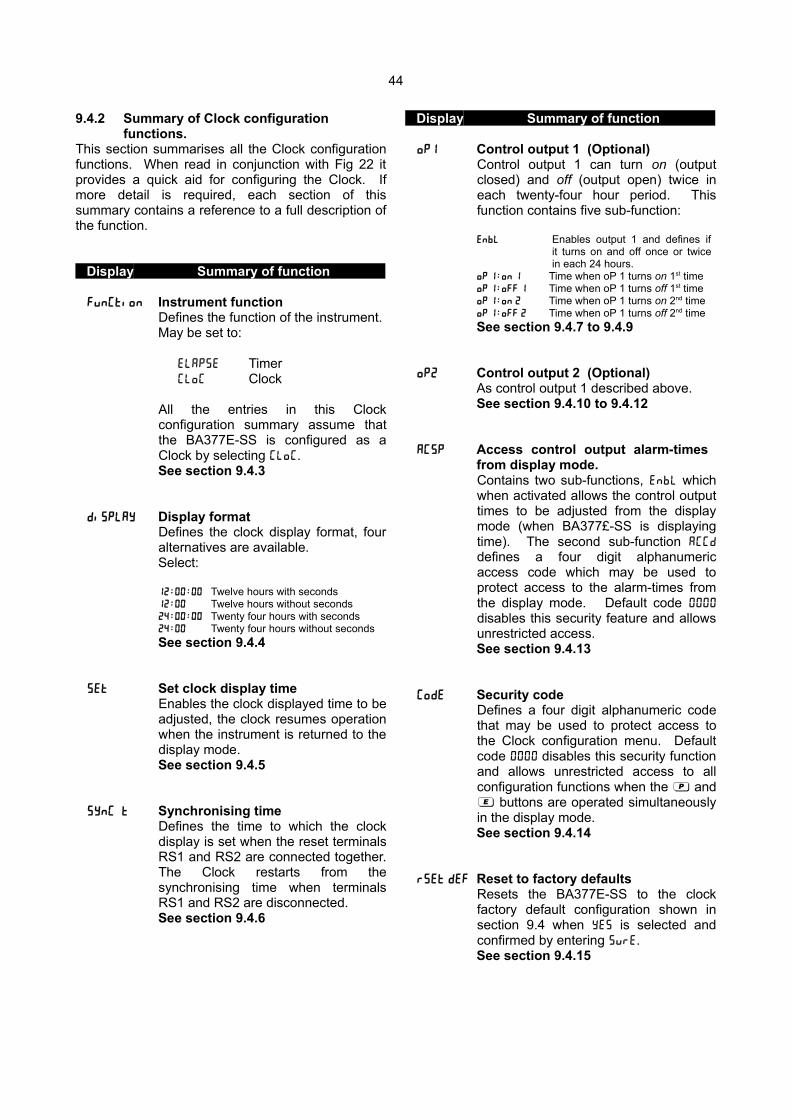
44
9.4.2 Summary of Clock configuration functions.
This section summarises all the Clock configurationfunctions. When read in conjunction with Fig 22 itprovides a quick aid for configuring the Clock. Ifmore detail is required, each section of thissummary contains a reference to a full description ofthe function.
Display Summary of function
FunCtion Instrument functionDefines the function of the instrument.May be set to:
ELAP5E TimerCloC Clock
All the entries in this Clockconfiguration summary assume thatthe BA377E-SS is configured as aClock by selecting CLoC.See section 9.4.3
di5PLAY Display formatDefines the clock display format, fouralternatives are available.Select:
12 : 00 : 00 Twelve hours with seconds12 : 00 Twelve hours without seconds24 : 00 : 00 Twenty four hours with seconds24 : 00 Twenty four hours without secondsSee section 9.4.4
5Et Set clock display timeEnables the clock displayed time to beadjusted, the clock resumes operationwhen the instrument is returned to thedisplay mode.See section 9.4.5
5YnC t Synchronising timeDefines the time to which the clockdisplay is set when the reset terminalsRS1 and RS2 are connected together.The Clock restarts from thesynchronising time when terminalsRS1 and RS2 are disconnected.See section 9.4.6
Display Summary of function
oP1 Control output 1 (Optional)Control output 1 can turn on (outputclosed) and off (output open) twice ineach twenty-four hour period. Thisfunction contains five sub-function:
EnbL Enables output 1 and defines if it turns on and off once or twice in each 24 hours.
oP 1 : on 1 Time when oP 1 turns on 1st timeoP 1 : oFF 1 Time when oP 1 turns off 1st timeoP 1 : on 2 Time when oP 1 turns on 2nd timeoP 1 : oFF 2 Time when oP 1 turns off 2nd timeSee section 9.4.7 to 9.4.9
oP2 Control output 2 (Optional)As control output 1 described above.See section 9.4.10 to 9.4.12
AC5P Access control output alarm-times from display mode.Contains two sub-functions, EnbL whichwhen activated allows the control outputtimes to be adjusted from the displaymode (when BA377£-SS is displayingtime). The second sub-function ACCd
defines a four digit alphanumericaccess code which may be used toprotect access to the alarm-times fromthe display mode. Default code 0000
disables this security feature and allowsunrestricted access.See section 9.4.13
CodE Security codeDefines a four digit alphanumeric codethat may be used to protect access tothe Clock configuration menu. Defaultcode 0000 disables this security functionand allows unrestricted access to allconfiguration functions when the ( and) buttons are operated simultaneouslyin the display mode.See section 9.4.14
r5Et dEF Reset to factory defaultsResets the BA377E-SS to the clockfactory default configuration shown insection 9.4 when YE5 is selected andconfirmed by entering 5uRE.See section 9.4.15

45
9.4.3 Instrument function: FunCtion
The BA377E-SS may be configured as a Timer or asa Clock. This section of the instruction manualdescribes the Clock configuration, for details ofTimer configuration see section 6.5.
To reveal the existing function of the instrumentselect FunCtion from the configuration menu andpress (. If CLoC is displayed, the instrument isalready configured as a Clock therefore press ) toreturn to the FunCtion prompt in the configurationmenu. If ELAP5E is displayed, press the * or &
button to change the setting to CLoC followed by the( button which will result in a 0000 prompt beingdisplayed with the first digit flashing. This is arequest for the instruction to be confirmed byentering 5urE using the * or & button to adjustthe flashing digit and the ( button to move controlto the next digit. When 5urE has been entered,pressing ) will change the instrument to a Clockand return the instrument to the display mode. Toconfigure the Clock enter the configuration menu bypressing the ( and ) buttons simultaneously untilfunction is displayed.
9.4.4 Display format: di5PLAY
The BA377E-SS Clock may be configured to displaytime in a 12 or 24 hour format with or withoutseconds. When a 12 hour format is selected, AM isdenoted by an A prefix at the left hand side of thedisplay, similarly a P is displayed to denote PM.
To check or change the display format of the clock,select di5PLAY from the configuration menu andpress ( which will reveal the existing setting whichcan be changed by pressing the * or & buttonfollowed by the ) button to enter the selection andreturn to the configuration menu. The optionsavailable are shown below:
12 : 00 : 00 Twelve hour format with seconds12 : 00 Twelve hour format without seconds24 : 00 : 00 Twenty four hour format with seconds24 : 00 Twenty four hour format without seconds
9.4.5 Set clock display time: 5Et
This function sets the time displayed by the Clockwhich must be entered each time the BA377E-SSClock is powered. Until a set time is entered theClock will display a flashing 00 : 00 : 00 or 00 : 00 for 24hour formats, or A12 : 00 : 00 or A12 : 00 for 12 hourformats.
To adjust the clock set time, select 5Et from theconfiguration menu and press ( that will show00 : 00 : 00 or the existing set time with the hoursflashing. When setting the clock display timeseconds are always shown.
Using the * or & button adjust the flashing hoursand then press ( to transfer control to the minutesdisplay, pressing ( again will transfer control to theseconds display. When the clock display time hasbeen adjusted press ) to start the Clock and returnto the 5Et prompt in the configuration menu.
9.4.6 Enter synchronising time: 5YnC t
When the external reset terminals RS1 and RS2 areconnected together the clock is stopped and thedisplayed time is set to the synchronising time.When the connection between the reset terminals isremoved, the clock restarts from the synchronisingtime. This function enables the BA377E-SS clock tobe synchronised with a master clock.
To enter the synchronising time, select 5YnC t fromthe configuration menu and press ( which willreveal the existing synchronising time with the hoursflashing. Using the * or & button adjust thehours and then press ( to transfer control to theminutes display, pressing ( again will transfercontrol to the seconds display. When thesynchronising time has been set as required, press) to return to the configuration menu.
9.4.7 Control output 1 (Optional): oP1
Control output 1 is an optional factory fittedgalvanically isolated solid state switch contact outputwhich can be configured to turn on (output closed)and off (output open) twice in each twenty-four hourperiod. The control output status is shown by the 1control output display annunciator.
Function oP1 contains a sub-menu with five sub-functions:
EnbL Number of times output 1turns on & off in 24 hours.
oP 1 : on 1 First time oP 1 turns on (closes)oP 1 : oFF 1 First time oP 1 turns off (opens)oP 1 : on 2 Second time oP 1 turns on (closes)oP 1 : oFF 2 Second time oP 1 turns off (opens)
To check or change the function of Control output 1select oP1 from the configuration menu and press( which will reveal the first sub-function EnbL.
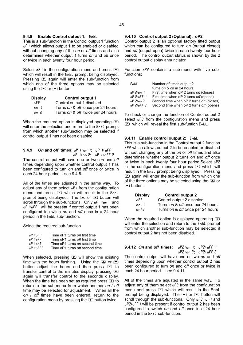
46
9.4.8 Enable Control output 1: EnbL
This is a sub-function in the Control output 1 functionoP1 which allows output 1 to be enabled or disabledwithout changing any of the on or off times and alsodetermines whether output 1 turns on and off onceor twice in each twenty four hour period.
Select oP1 in the configuration menu and press (
which will result in the EnbL prompt being displayed.Pressing ( again will enter the sub-function fromwhich one of the three options may be selectedusing the * or & button:
Display Control output 1oFF Control output 1 disabledon : 1 Turns on & off once per 24 hourson : 2 Turns on & off twice per 24 hours
When the required option is displayed operating )will enter the selection and return to the EnbL promptfrom which another sub-function may be selected ifcontrol output 1 has not been disabled.
9.4.9 On and off times: oP 1 : on 1; oP 1 : off 1
oP 1 : on 2; oP 1 : off 2
The control output will have one or two on and offtimes depending upon whether control output 1 hasbeen configured to turn on and off once or twice ineach 24 hour period. - see 9.4.8.
All of the times are adjusted in the same way. Toadjust any of them select oP1 from the configurationmenu and press ( which will result in the EnbL
prompt being displayed. The * or & button willscroll through the sub-functions. Only oP 1 : on 1 andoP1 : oFF1 will be present if control output 1 has beenconfigured to switch on and off once in a 24 hourperiod in the EnbL sub-function.
Select the required sub-function
oP1 : on1 Time oP1 turns on first timeoP1 : oFF1 Time oP1 turns off first timeoP1 : on2 Time oP1 turns on second timeoP1 : oFF2 Time oP1 turns off second time
When selected, pressing ( will show the existingtime with the hours flashing. Using the * or &
button adjust the hours and then press ( totransfer control to the minutes display, pressing (
again will transfer control to the seconds display.When the time has been set as required press ) toreturn to the sub-menu from which another on / offtime may be selected for adjustment. When all theon / off times have been entered, return to theconfiguration menu by pressing the ) button twice.
9.4.10 Control output 2 (Optional): oP2Control output 2 is an optional factory fitted outputwhich can be configured to turn on (output closed)and off (output open) twice in each twenty-four hourperiod. The control output status is shown by the 2control output display annunciator.
Function oP2 contains a sub-menu with five sub-functions:
EnbL Number of times output 2turns on & off in 24 hours.
oP 2 : on 1 First time when oP 2 turns on (closes)oP 2 : oFF 1 First time when oP 2 turns off (opens)oP 2 : on 2 Second time when oP 2 turns on (closes)oP 2 : oFF 2 Second time when oP 2 turns off (opens)
To check or change the function of Control output 2select oP2 from the configuration menu and press( which will reveal the first sub-funtion EnbL.
9.4.11 Enable control output 2: EnbL
This is a sub-function in the Control output 2 functionoP2 which allows output 2 to be enabled or disabledwithout changing any of the on or off times and alsodetermines whether output 2 turns on and off onceor twice in each twenty four hour period.Select oP2
in the configuration menu and press ( which willresult in the EnbL prompt being displayed. Pressing( again will enter the sub-function from which oneof the three options may be selected using the * or& button:
Display Control output 2oFF Control output 2 disabledon : 1 Turns on & off once per 24 hourson : 2 Turns on & off twice per 24 hours
When the required option is displayed operating )will enter the selection and return to the EnbL promptfrom which another sub-function may be selected ifcontrol output 2 has not been disabled.
9.4.12 On and off times: oP2 : on 1; oP2 : off 1
oP2 : on 2; oP2 : off 2
The control output will have one or two on and offtimes depending upon whether control output 2 hasbeen configured to turn on and off once or twice ineach 24 hour period. - see 9.4.11.
All of the times are adjusted in the same way. Toadjust any of them select oP2 from the configurationmenu and press ( which will result in the EnbLprompt being displayed. The * or & button willscroll through the sub-functions. Only oP2 : on1 andoP2 : oFF1 will be present if control output 2 has beenconfigured to switch on and off once in a 24 hourperiod in the EnbL sub-function.
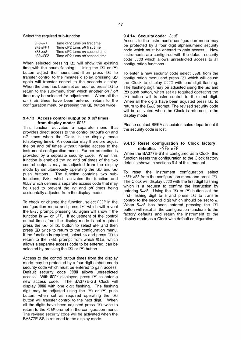
47
Select the required sub-function
oP2 : on1 Time oP2 turns on first timeoP2 : oFF1 Time oP2 turns off first timeoP2 : on2 Time oP2 turns on second timeoP2 : oFF2 Time oP2 turns off second time
When selected pressing ( will show the existingtime with the hours flashing. Using the * or &
button adjust the hours and then press ( totransfer control to the minutes display, pressing (
again will transfer control to the seconds display.When the time has been set as required press ) toreturn to the sub-menu from which another on / offtime may be selected for adjustment. When all theon / off times have been entered, return to theconfiguration menu by pressing the ) button twice.
9.4.13 Access control output on & off times from display mode: AC5P
This function activates a separate menu thatprovides direct access to the control output's on andoff times when the Clock is the display mode(displaying time). An operator may therefore adjustthe on and off times without having access to theinstrument configuration menu. Further protection isprovided by a separate security code. When thisfunction is enabled the on and off times of the twocontrol outputs may be adjusted from the displaymode by simultaneously operating the ( and *
push buttons. The function contains two sub-functions, EnbL which activates the function andACCd which defines a separate access code that maybe used to prevent the on and off times beingaccidentally adjusted from the display mode.
To check or change the function, select AC5P in theconfiguration menu and press ( which will revealthe EnbL prompt, pressing ( again will show if thefunction is on or oFF. If adjustment of the controloutput times from the display mode is not requiredpress the * or & button to select off and thenpress ) twice to return to the configuration menu.If the function is required, select on and press ) toreturn to the EnbL prompt from which ACCd, whichallows a separate access code to be entered, can beselected by pressing the * or & button.
Access to the control output times from the displaymode may be protected by a four digit alphanumericsecurity code which must be entered to gain access.Default security code 0000 allows unrestrictedaccess. With ACCd displayed, press ( to enter anew access code. The BA377E-SS Clock willdisplay 0000 with one digit flashing. The flashingdigit may be adjusted using the * or & pushbutton, when set as required operating the (
button will transfer control to the next digit. Whenall the digits have been adjusted press ) twice toreturn to the AC5P prompt in the configuration menu.The revised security code will be activated when theBA377E-SS is returned to the display mode.
9.4.14 Security code: CodE
Access to the instrument's configuration menu maybe protected by a four digit alphanumeric securitycode which must be entered to gain access. Newinstruments are configured with the default securitycode 0000 which allows unrestricted access to allconfiguration functions.
To enter a new security code select CodE from theconfiguration menu and press ( which will causethe Clock to display 0000 with one digit flashing.The flashing digit may be adjusted using the * and& push button, when set as required operating the( button will transfer control to the next digit.When all the digits have been adjusted press ) toreturn to the CodE prompt. The revised security codewill be activated when the Clock is returned to thedisplay mode.
Please contact BEKA associates sales department ifthe security code is lost.
9.4.15 Reset configuration to Clock factory defaults:. r5Et dEF
When the BA377E-SS is configured as a Clock, thisfunction resets the configuration to the Clock factorydefaults shown in sections 9.4 of this manual.
To reset the instrument configuration selectr5Et dEF from the configuration menu and press (.The Clock will display 0000 with the first digit flashingwhich is a request to confirm the instruction byentering 5urE. Using the * or & button set thefirst flashing digit to 5 and press ( to transfercontrol to the second digit which should be set to u.When 5urE has been entered pressing the )button will reset all the configuration functions to thefactory defaults and return the instrument to thedisplay mode as a Clock with default configuration.
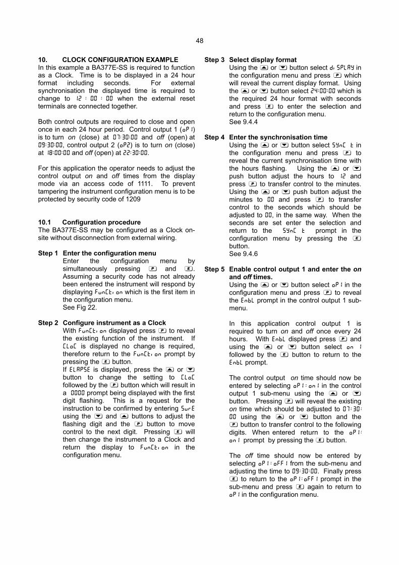
48
10. CLOCK CONFIGURATION EXAMPLEIn this example a BA377E-SS is required to functionas a Clock. Time is to be displayed in a 24 hourformat including seconds. For externalsynchronisation the displayed time is required tochange to 12 : 00 : 00 when the external resetterminals are connected together.
Both control outputs are required to close and openonce in each 24 hour period. Control output 1 (oP1)is to turn on (close) at 07 : 30 : 00 and off (open) at09 : 30 : 00, control output 2 (oP2) is to turn on (close)at 18 : 00 : 00 and off (open) at 22 : 30 : 00.
For this application the operator needs to adjust thecontrol output on and off times from the displaymode via an access code of 1111. To preventtampering the instrument configuration menu is to beprotected by security code of 1209
10.1 Configuration procedureThe BA377E-SS may be configured as a Clock on-site without disconnection from external wiring.
Step 1 Enter the configuration menuEnter the configuration menu bysimultaneously pressing ( and ).Assuming a security code has not alreadybeen entered the instrument will respond bydisplaying FunCtion which is the first item inthe configuration menu.See Fig 22.
Step 2 Configure instrument as a ClockWith FunCtion displayed press ( to revealthe existing function of the instrument. IfCloc is displayed no change is required,therefore return to the FunCtion prompt bypressing the ) button.If ELAP5E is displayed, press the * or &button to change the setting to CLoC
followed by the ( button which will result ina 0000 prompt being displayed with the firstdigit flashing. This is a request for theinstruction to be confirmed by entering 5urE
using the & and * buttons to adjust theflashing digit and the ( button to movecontrol to the next digit. Pressing ) willthen change the instrument to a Clock andreturn the display to FunCtion in theconfiguration menu.
Step 3 Select display formatUsing the * or & button select di5PLAY inthe configuration menu and press ( whichwill reveal the current display format. Usingthe * or & button select 24 : 00 : 00 which isthe required 24 hour format with secondsand press ) to enter the selection andreturn to the configuration menu.See 9.4.4
Step 4 Enter the synchronisation timeUsing the * or & button select 5YnC t inthe configuration menu and press ( toreveal the current synchronisation time withthe hours flashing. Using the * or &push button adjust the hours to 12 andpress ( to transfer control to the minutes.Using the * or & push button adjust theminutes to 00 and press ( to transfercontrol to the seconds which should beadjusted to 00, in the same way. When theseconds are set enter the selection andreturn to the 5YnC t prompt in theconfiguration menu by pressing the )button.See 9.4.6
Step 5 Enable control output 1 and enter the onand off times.Using the * or & button select oP1 in theconfiguration menu and press ( to revealthe EnbL prompt in the control output 1 sub-menu.
In this application control output 1 isrequired to turn on and off once every 24hours. With EnbL displayed press ( andusing the * or & button select on 1
followed by the ) button to return to theEnbL prompt.
The control output on time should now beentered by selecting oP1 : on1 in the controloutput 1 sub-menu using the * or &button. Pressing ( will reveal the existingon time which should be adjusted to 07 : 30 :
00 using the * or & button and the( button to transfer control to the followingdigits. When entered return to the oP1 :
on1 prompt by pressing the ) button.
The off time should now be entered byselecting oP1 : oFF1 from the sub-menu andadjusting the time to 09 : 30 : 00. Finally press) to return to the oP1 : oFF1 prompt in thesub-menu and press ) again to return tooP1 in the configuration menu.

49
Step 6 Enable control output 2 and enter the onand off times.Using the * or & button select oP2 in theconfiguration menu and press ( to revealthe EnbL prompt in the control output 2 sub-menu. Follow the procedure described instep 5 above, but set control output 2 to turnon at 18 : 00 : 00 and off at 22 : 30 : 00.
Step 7 Allow control output times to be adjustedfrom the display mode & enter separatesecurity code.Using the * or & button select AC5P in theconfiguration menu and press ( to revealthe EnbL prompt, pressing ( again willshow if this function is on or oFF. Using the* or & button select on followed by ) toreturn to the EnbL prompt. A separatesecurity code which must be entered to gainaccess to the alarm times in the operatingmode, is entered in the ACCd function whichmay be selected by operating the * or &button once. Pressing ) will reveal theexisting access code with one digit flashing.This should be changed to the requiredcode of 1111 by adjusting the flashing digitusing using the * or & button and the (button to transfer control to the next digit.When 1111 has been entered press )twice to return to the configuration menu.
Step 8 Define the configuration menu securitycode.Defining a security code preventsunauthorised access to the configurationmenu. Using the & and * buttons selectCodE from the configuration menu and press( which will reveal 0000 with the first digitflashing. This example requires the securitycode to be 1209, using the & and *buttons set the flashing digit to 1 and press( to transfer control to the second digit.When all have been entered press ) toreturn to the main configuration menu.See 9.4.14.
Step 9 Return to the display modeThe BA377E-SS is now configured asrequired for this example. Pressing the )button will save the configuration and returnthe BA377E-SS to the display mode with allthe digits flashing indicating that the set timehas to be entered.
Step 10Enter the set timeFinally the current time to be displayed bythe Clock should be entered. Re-enter theconfiguration menu by pressing the ( and) buttons simultaneously which will resultin code being displayed. Pressing ( willallow the access code 1209 to be enteredusing the & or * button to adjust theflashing digit and the ( button to transfercontrol to the next digit. When all four digitshave been adjusted press ( to enter theconfiguration menu and using the & or *button select 5Et and press ) to reveal00 : 00 : 00 with the hours flashing. Using the& or * button adjust the flashing hoursdigit and press ( to transfer control to theminutes and then to the seconds. When allhave been set as required, press ) to startthe clock from the entered time and return tothe display mode.
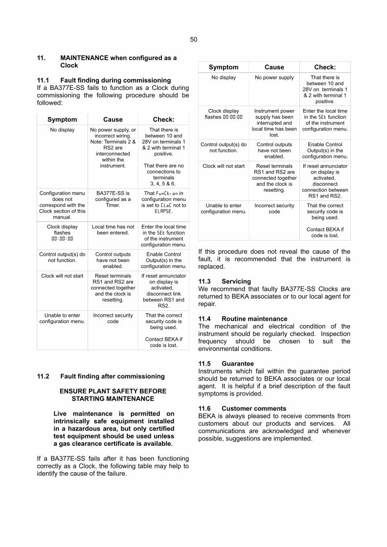
50
11. MAINTENANCE when configured as a Clock
11.1 Fault finding during commissioningIf a BA377E-SS fails to function as a Clock duringcommissioning the following procedure should befollowed:
Symptom Cause Check:
No display No power supply, orincorrect wiring.
Note: Terminals 2 &RS2 are
interconnectedwithin the
instrument.
That there isbetween 10 and
28V on terminals 1& 2 with terminal 1
positive.
That there are noconnections to
terminals3, 4, 5 & 6.
Configuration menudoes not
correspond with theClock section of this
manual.
BA377E-SS isconfigured as a
Timer.
That FunCtion inconfiguration menuis set to CLoC not to
ELAP5E.
Clock displayflashes
00 : 00 : 00
Local time has notbeen entered.
Enter the local timein the 5Et functionof the instrument
configuration menu.
Control output(s) donot function.
Control outputshave not been
enabled.
Enable ControlOutput(s) in the
configuration menu.
Clock will not start Reset terminalsRS1 and RS2 are
connected togetherand the clock is
resetting.
If reset annunciatoron display isactivated,
disconnect linkbetween RS1 and
RS2.
Unable to enterconfiguration menu.
Incorrect securitycode
That the correctsecurity code is
being used.
Contact BEKA ifcode is lost.
11.2 Fault finding after commissioning
ENSURE PLANT SAFETY BEFORESTARTING MAINTENANCE
Live maintenance is permitted onintrinsically safe equipment installedin a hazardous area, but only certifiedtest equipment should be used unlessa gas clearance certificate is available.
If a BA377E-SS fails after it has been functioningcorrectly as a Clock, the following table may help toidentify the cause of the failure.
Symptom Cause Check:
No display No power supply That there isbetween 10 and
28V on terminals 1& 2 with terminal 1
positive.
Clock displayflashes 00 : 00 : 00
Instrument powersupply has beeninterrupted and
local time has beenlost.
Enter the local timein the 5Et functionof the instrument
configuration menu.
Control output(s) donot function.
Control outputshave not been
enabled.
Enable ControlOutput(s) in the
configuration menu.
Clock will not start Reset terminalsRS1 and RS2 are
connected togetherand the clock is
resetting.
If reset annunciatoron display isactivated, disconnect
connection betweenRS1 and RS2.
Unable to enterconfiguration menu.
Incorrect securitycode
That the correctsecurity code is
being used.
Contact BEKA ifcode is lost.
If this procedure does not reveal the cause of thefault, it is recommended that the instrument isreplaced.
11.3 ServicingWe recommend that faulty BA377E-SS Clocks arereturned to BEKA associates or to our local agent forrepair.
11.4 Routine maintenanceThe mechanical and electrical condition of theinstrument should be regularly checked. Inspectionfrequency should be chosen to suit theenvironmental conditions.
11.5 GuaranteeInstruments which fail within the guarantee periodshould be returned to BEKA associates or our localagent. It is helpful if a brief description of the faultsymptoms is provided.
11.6 Customer commentsBEKA is always pleased to receive comments fromcustomers about our products and services. Allcommunications are acknowledged and wheneverpossible, suggestions are implemented.
51
Appendix 1Dust certification
A1.0 ATEX dust certificationIn addition to ATEX certification permittinginstallation in explosive gas atmospheres which isdescribed in the main section of this instructionmanual, the BA377E-SS Timer or Clock has ATEXcertification permitting installation in combustibledust atmospheres.
This appendix describes ATEX installations inexplosive dust atmospheres conforming withEN 60079-14 Electrical installations design,selection and erection. When designing systems forinstallation outside the UK the local Code of Practiceshould be consulted.
The Timer or Clock's dust input and output safetyparameters are identical to its gas parameters,therefore all the electrical circuits shown in the mainsection of this manual may also be used for dustapplications. Intrinsically safe systems in dustatmospheres only have to comply with IIBrequirements. Apparatus certificates for intrinsicallysafe interfaces usually specify Co and Lo for IICgases, but for use with apparatus in dustatmospheres these may be increased to the IIBfigures. For a IIC interface with a Uo of 28V and anIo of 93mA, Co increases from 83nF to 650nF andLo increases by a factor of 4 for IIB.
A1.1 Zones, and Maximum Surface Temperature.
The BA377E-SS has been ATEX dust certified as
Group II, Category 1D Ex ia IIIC T80ºC Da -40 ≤ Ta ≤ 60°C
When connected to a suitable system theBA377E-SS may be installed in:
Zone 20 explosive atmosphere in the form of acloud of combustible dust in air iscontinuously present, or for longperiods or frequently.
Zone 21 explosive atmosphere in the form of acloud of combustible dust in air islikely to occur occasionally in normaloperation.
Zone 22 explosive atmosphere in the form of acloud of combustible dust in air is notlikely to occur in normal operation, butif it does occur, will only persist for ashort period.
Be used with dust in subdivisions:
IIIA combustible flyings
IIIB non-conductive dust
IIIC conductive dust (For use with IIIC conductive dustsspecial conditions for safe useapply – see section A1.4)
Having a Minimum Ignition Temperature of:
Dust cloud 120°C
Dust layer on indicator 155°Cup to 5mm thick
Dust layer on indicator Refer toover 5mm thick. EN 60079-14
At an ambient temperature between -40 and +60°C
A1.3 Maintenance
ENSURE PLANT SAFETY BEFORESTARTING MAINTENANCE
Live maintenance is permitted onintrinsically safe equipment installed in ahazardous area, but only certified testequipment should be used.
The BA377E-SS has IP66 front of panel protectionand a gasket is provided to seal the joint betweenthe instrument and the mounting panel thuspreventing dust ingress from the outside. The rearof the instrument has IP20 protection therefore whenused in any dust application the panel enclosure inwhich the instrument is mounted should provide atleast IP54 ingress protection. For applications in IIICconductive dusts, IP6X protection is required.
A1.4 Special conditions for safe useThe ATEX certificate has an ‘X’ suffix indicating thatspecial conditions for safe use are required forinstallation dust atmospheres, the certificate states:
• For use in group III explosive dust atmospheres the BA377E-SS shall be mounted such that the rear of the instrumenthas at least IP54 protection.
• For use in group IIIC conductive explosive dust atmospheres the BA377E-SS shall be mounted such that the rear terminals have at least IP6X protection.
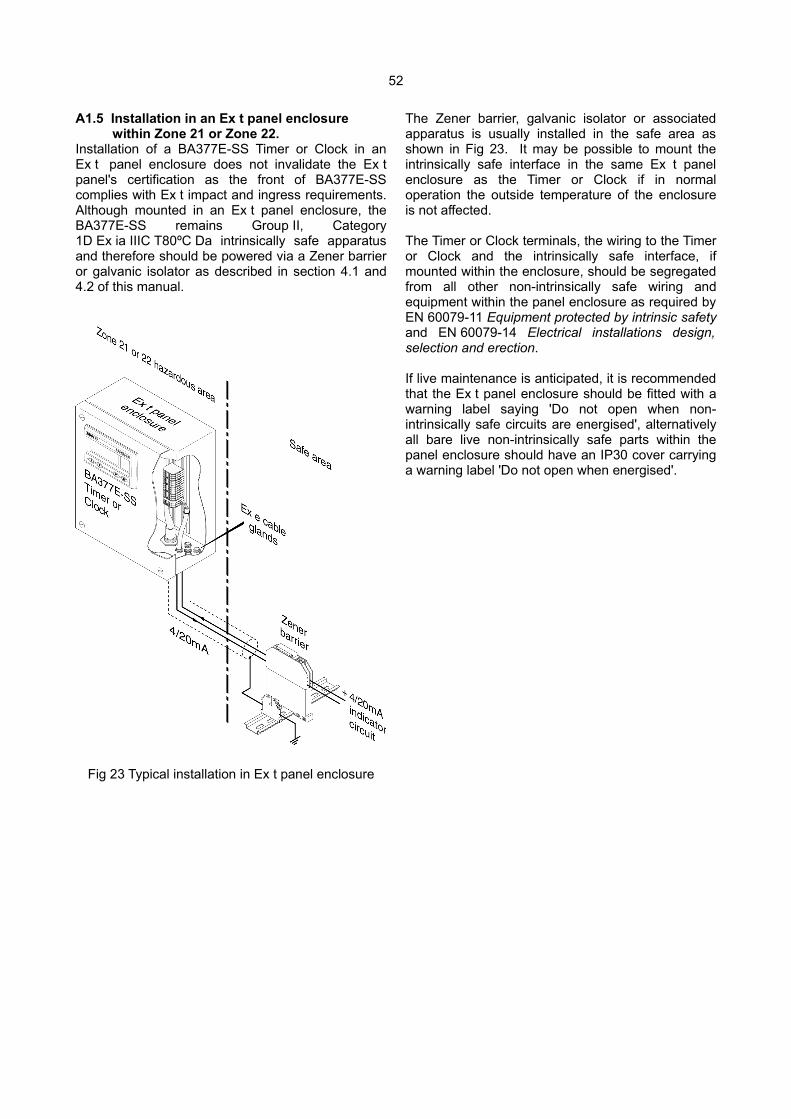
52
A1.5 Installation in an Ex t panel enclosure within Zone 21 or Zone 22. Installation of a BA377E-SS Timer or Clock in anEx t panel enclosure does not invalidate the Ex tpanel's certification as the front of BA377E-SScomplies with Ex t impact and ingress requirements.Although mounted in an Ex t panel enclosure, theBA377E-SS remains Group II, Category1D Ex ia IIIC T80ºC Da intrinsically safe apparatusand therefore should be powered via a Zener barrieror galvanic isolator as described in section 4.1 and4.2 of this manual.
Fig 23 Typical installation in Ex t panel enclosure
The Zener barrier, galvanic isolator or associatedapparatus is usually installed in the safe area asshown in Fig 23. It may be possible to mount theintrinsically safe interface in the same Ex t panelenclosure as the Timer or Clock if in normaloperation the outside temperature of the enclosureis not affected.
The Timer or Clock terminals, the wiring to the Timeror Clock and the intrinsically safe interface, ifmounted within the enclosure, should be segregatedfrom all other non-intrinsically safe wiring andequipment within the panel enclosure as required byEN 60079-11 Equipment protected by intrinsic safetyand EN 60079-14 Electrical installations design,selection and erection.
If live maintenance is anticipated, it is recommendedthat the Ex t panel enclosure should be fitted with awarning label saying 'Do not open when non-intrinsically safe circuits are energised', alternativelyall bare live non-intrinsically safe parts within thepanel enclosure should have an IP30 cover carryinga warning label 'Do not open when energised'.
53
Appendix 2 IECEx certification
A2.0 The IECEx Certification SchemeIECEx is a global certification scheme for explosionprotected products which aims to harmoniseinternational certification standards. For additionalinformation about the IECEx certification schemeand to view the BEKA associate certificates, pleasevisit www.iecex.com
A2.1 IECEx Certificate of ConformityThe BA377E-SS Timer or Clock has been issuedwith an IECEx Certificate of Conformity numberIECEx ITS 16.0004X which specifies the followingcertification code:
Ex ia IIC T5 Ga Ex ia IIIC T 80ºC Da -40ºC ≤ Ta ≤ +60ºC
When installed as purely intrinsically safe apparatusi.e. when not relying upon ingress and impactresistance of the Timer or Clock front in an Ex e,Ex p, Ex n or Ex t panel enclosure ambienttemperature range is increased to-40ºC ≤ Ta ≤ +70ºC
The IECEx certificate may be downloaded fromwww.beka.co.uk, www.iecex.com or requested fromthe BEKA sales office.
A2.2 InstallationThe IECEx intrinsic safety parameters are identicalto the ATEX safety parameters described in the mainsection of this manual and both refer to the samestandards. Therefore the ATEX installationrequirements specified in sections 2, 3 and Appendix1 of this manual may be used for IECExinstallations, but the local code of practice shouldalso be consulted.
A2.3 Special conditions for safe useThe IECEx intrinsic safety certificate number has an‘X’ suffix indicating that for some applications specialconditions apply for safe use.
• For use in group III explosive dust atmospheres the BA377E-SS shall be mounted such that the rear of the instrumenthas at least IP54 protection.
• For use in group IIIC conductive explosive dust atmospheres the BA377E-SS shall be mounted such that the rear terminals have atleast IP6X protection.
This means that when installed in an Ex e, Ex n,Ex p or Ex t panel enclosure the BA377E-SSremains an intrinsically safe instrument and mustcomply with the installation requirements shown inthis manual.
The certificate also states:
The front of the stainless steel enclosurecomplies with the requirements for Ex e, Ex nEx p & Ex t type of protection.
Therefore when correctly installed in a certifiedpanel enclosure the BA377E-SS Timer or Clock willnot invalidate the Ex e, Ex n, Ex p or Ex t panelenclosure certification.
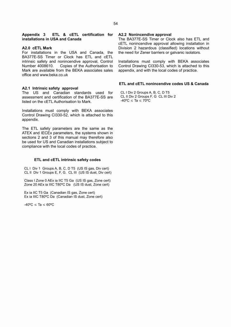
54
Appendix 3 ETL & cETL certification forinstallations in USA and Canada
A2.0 cETL MarkFor installations in the USA and Canada, theBA377E-SS Timer or Clock has ETL and cETLintrinsic safety and nonincendive approval, ControlNumber 4008610. Copies of the Authorisation toMark are available from the BEKA associates salesoffice and www.beka.co.uk
A2.1 Intrinsic safety approvalThe US and Canadian standards used forassessment and certification of the BA377E-SS arelisted on the cETL Authorisation to Mark.
Installations must comply with BEKA associatesControl Drawing CI330-52, which is attached to thisappendix.
The ETL safety parameters are the same as theATEX and IECEx parameters, the systems shown insections 2 and 3 of this manual may therefore alsobe used for US and Canadian installations subject tocompliance with the local codes of practice.
ETL and cETL intrinsic safety codes
CL I Div 1 Groups A, B, C, D T5 (US IS gas, Div cert) CL II Div 1 Groups E, F, G. CL III (US IS dust, Div cert)
Class I Zone 0 AEx ia IIC T5 Ga (US IS gas, Zone cert)Zone 20 AEx ia IIIC T80ºC Da (US IS dust, Zone cert)
Ex ia IIC T5 Ga (Canadian IS gas, Zone cert)Ex ia IIIC T80ºC Da (Canadian IS dust, Zone cert)
-40ºC Ta 60ºC
A2.2 Nonincendive approvalThe BA377E-SS Timer or Clock also has ETL andcETL nonincendive approval allowing installation inDivision 2 hazardous (classified) locations withoutthe need for Zener barriers or galvanic isolators.
Installations must comply with BEKA associatesControl Drawing CI330-53, which is attached to thisappendix, and with the local codes of practice.
ETL and cETL nonincendive codes US & Canada
CL I Div 2 Groups A, B, C, D T5CL II Div 2 Groups F, G CL III Div 2-40ºC Ta 70ºC
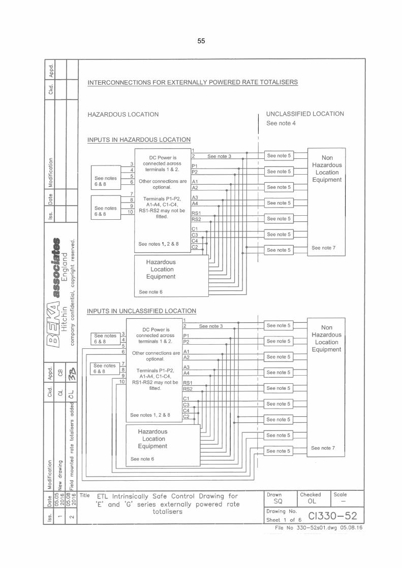
55
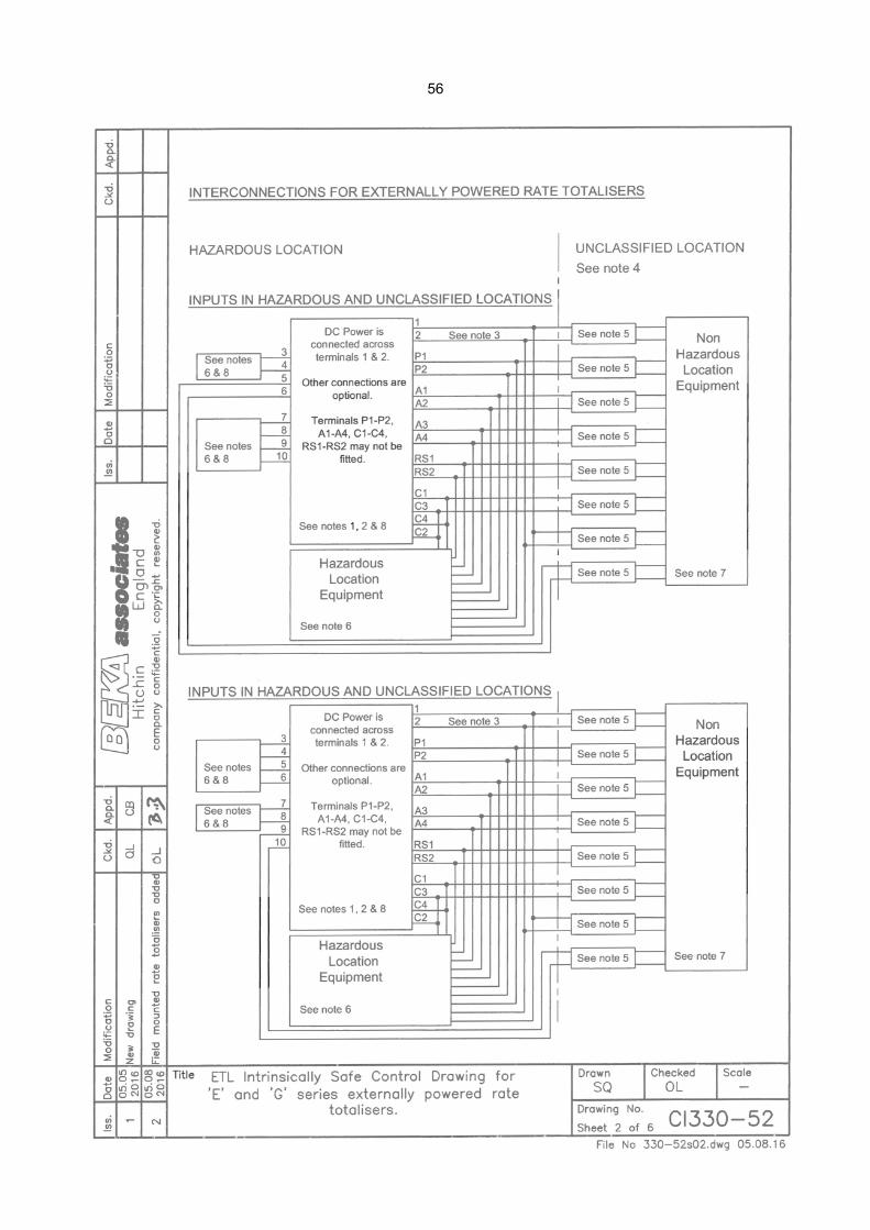
56
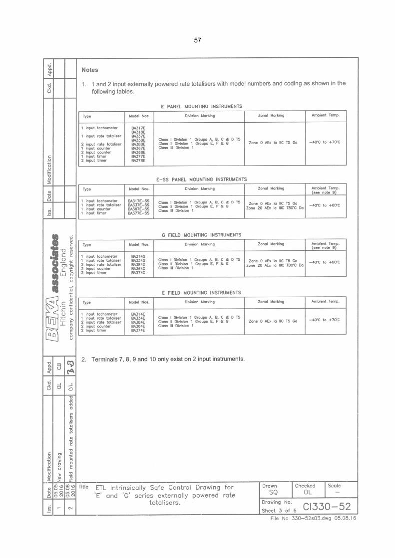
57
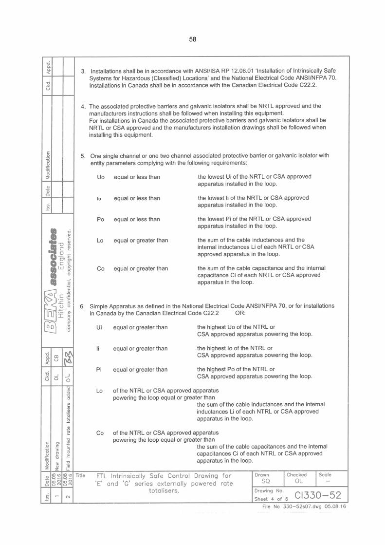
58
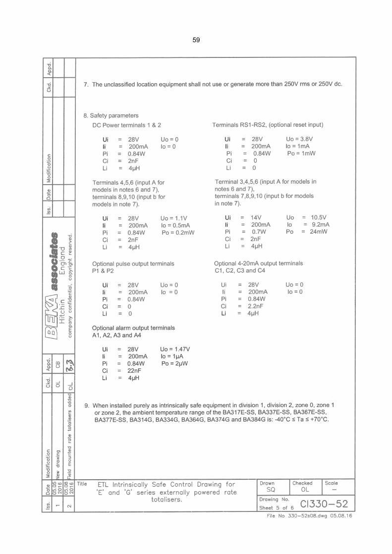
59
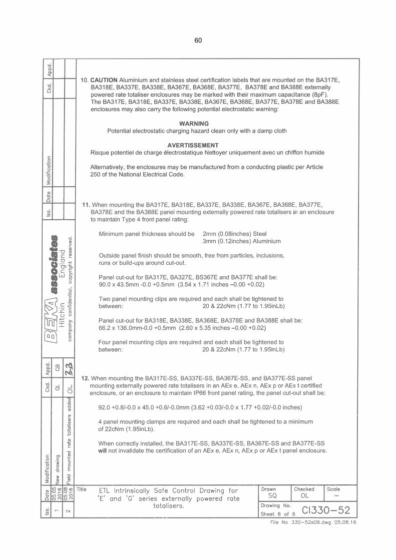
60
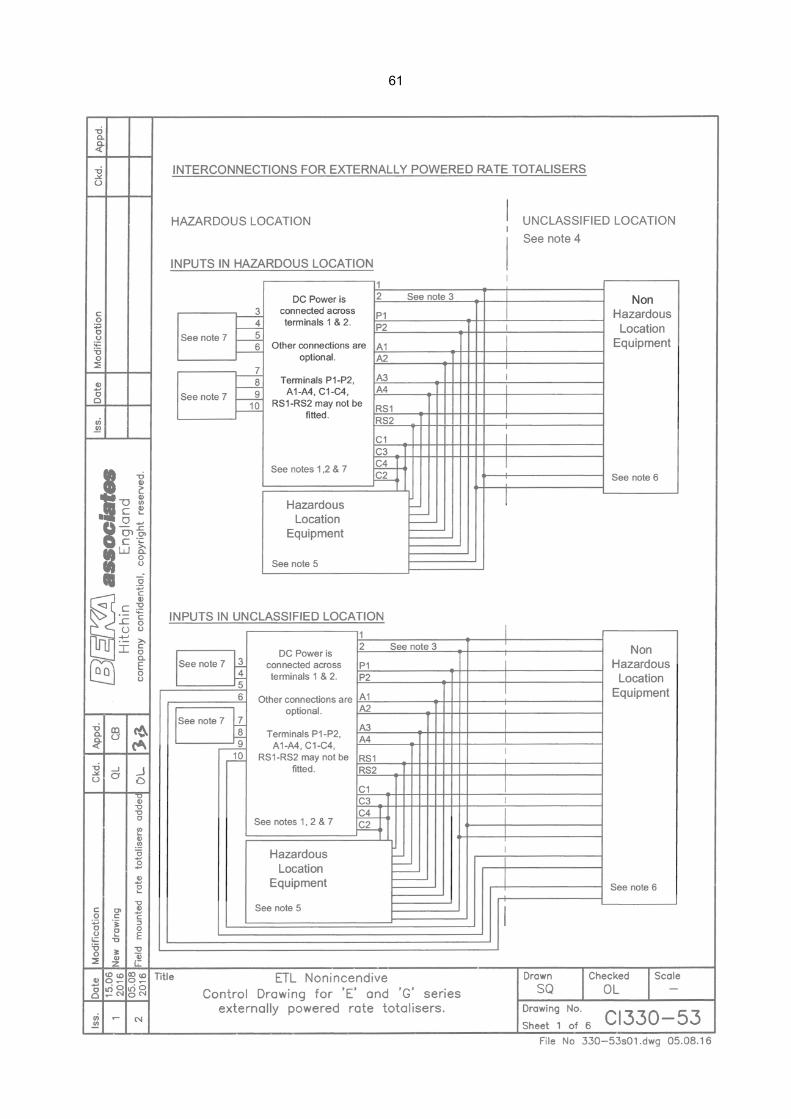
61
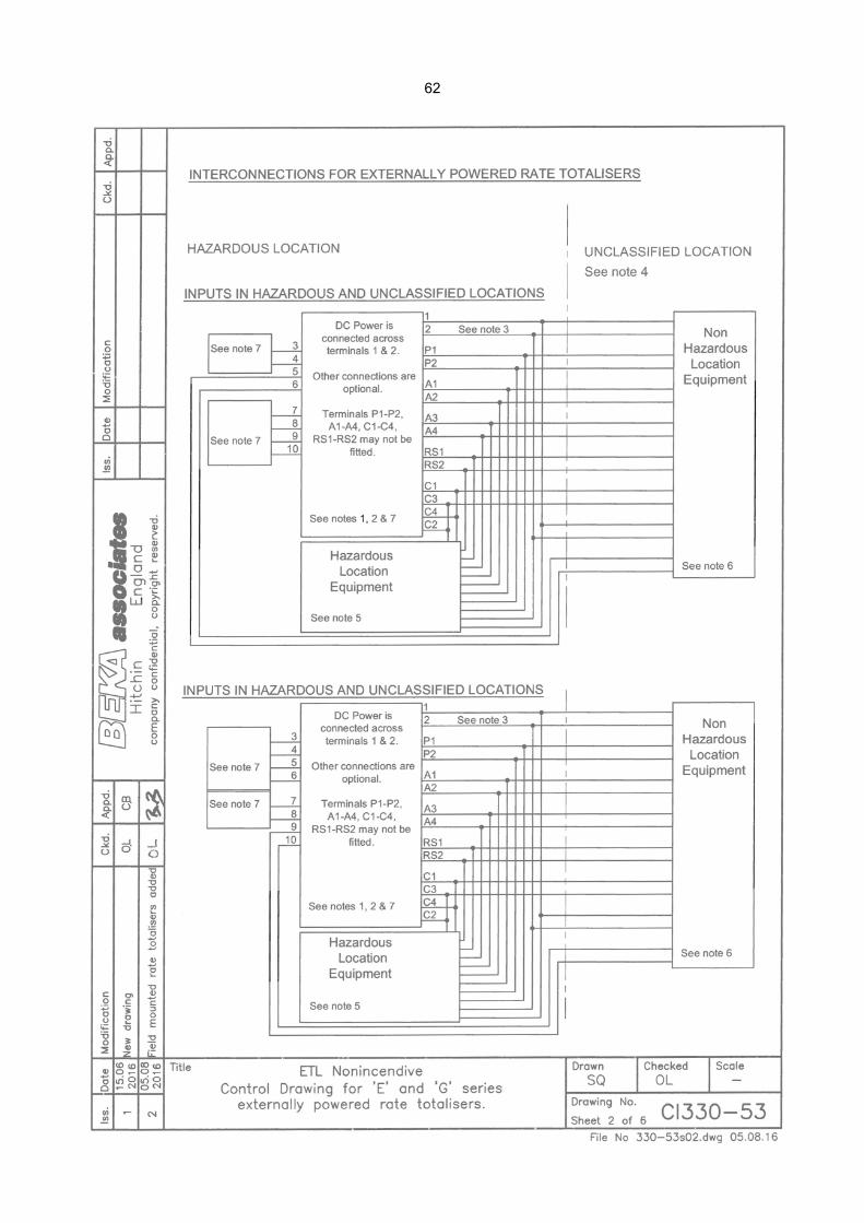
62
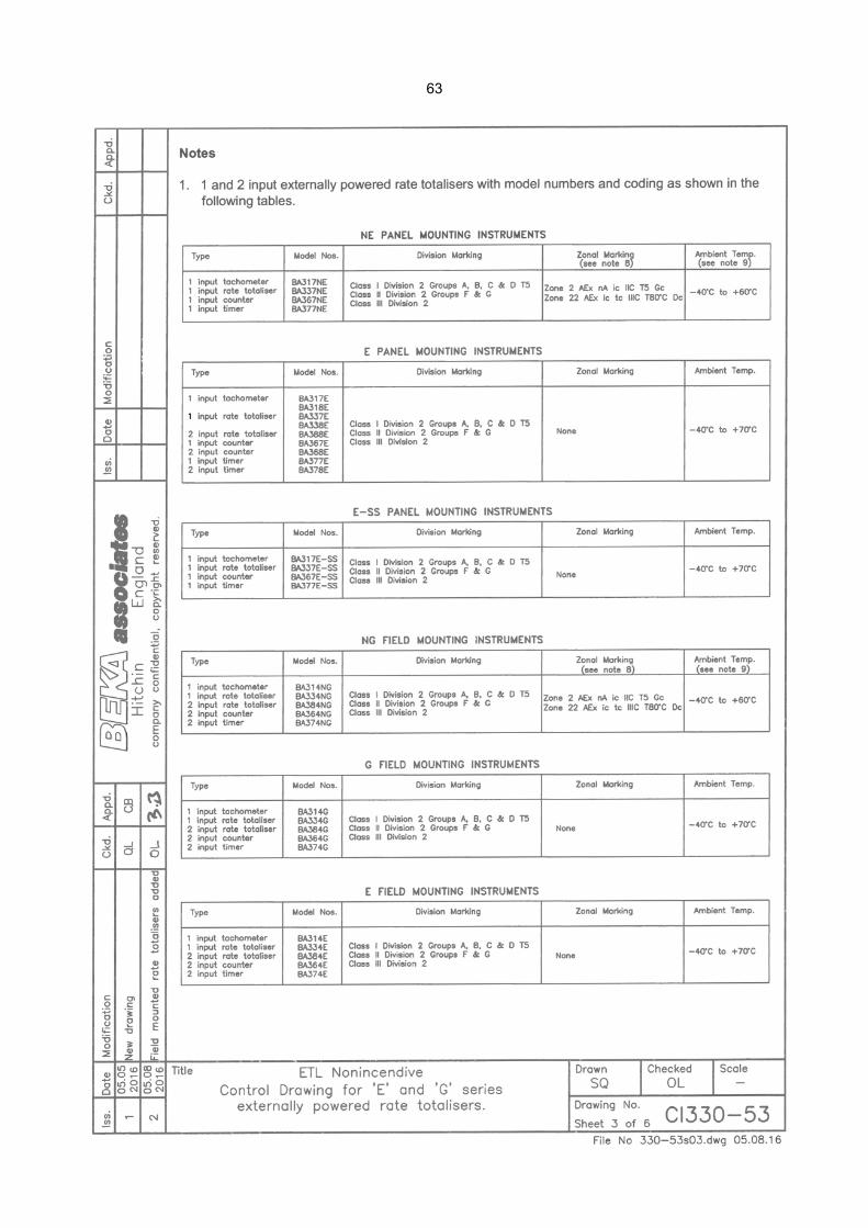
63
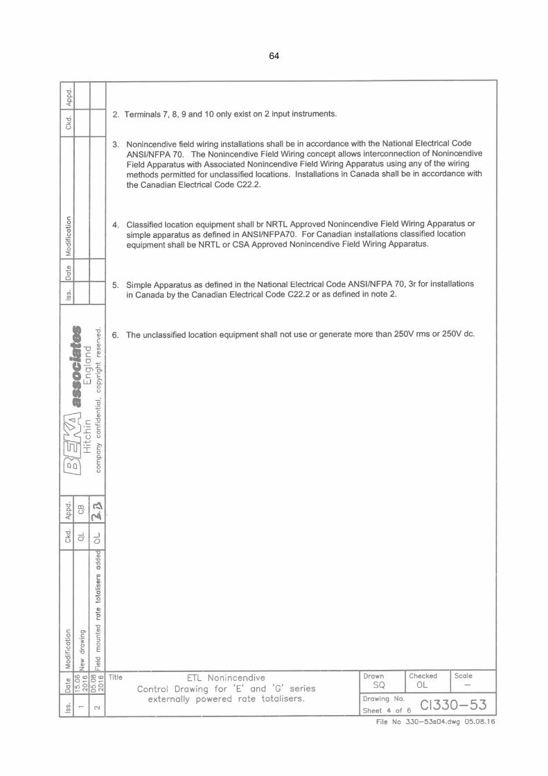
64

65

66