ba 463 usa print pf 8...g-class operator'smanual orderno.6515415913 partno.4635844300...
TRANSCRIPT
G-ClassOperator's Manual
Order no. 6515 4159 13 Part no. 463 584 43 00 Edition A 2014
É4635844300,ËÍ4635844300
G-Clas
sOperat
or'sM
anual
Publication detailsInternet
Further information about Mercedes-Benzvehicles and about Daimler AG can be foundon the following websites:http://www.mbusa.com (USA only)http://www.mercedes-benz.ca (Canadaonly)
Editorial office
©Daimler AG: Not to be reprinted, translatedor otherwise reproduced, in whole or in part,without written permission from Daimler AG.
Vehicle manufacturer
Daimler AGMercedesstraße 13770327 StuttgartGermany
SymbolsRegistered trademarks:RBluetooth® is a registered trademark ofBluetooth SIG Inc.RDTS is a registered trademark of DTS, Inc.RDolby and MLP are registered trademarksof DOLBY Laboratories.RBabySmart™, ESP® and PRE-SAFE® areregistered trademarks of Daimler AG.RHomeLink® is a registered trademark ofPrince.RiPod® and iTunes® are registeredtrademarks of Apple Inc.RLogic7® is a registered trademark ofHarman International Industries.RMicrosoft® and Windows media® areregistered trademarks of MicrosoftCorporation.RSIRIUS is a registered trademark of SiriusXM Radio Inc.RHD Radio is a registered trademark ofiBiquity Digital Corporation.RGracenote® is a registered trademark ofGracenote, Inc.RZAGATSurvey® and related brands areregistered trademarks of ZagatSurvey,LLC.
In this Operator's Manual you will find thefollowing symbols:
G WARNINGWarning notes draw your attention to hazardsthat endanger your health or life, or the healthor life of others.
H Environmental noteEnvironmental notes provide you withinformation on environmentally aware actionsor disposal.
! Notes on material damage alert you todangers that could lead to damage to yourvehicle.
i Practical tips or further information thatcould be helpful to you.
X This symbol indicates aninstruction that must be followed.
X Several of these symbols insuccession indicate an instructionwith several steps.
(Y page) This symbol tells you where youcan find more information about atopic.
YY This symbol indicates a warning oran instruction that is continued onthe next page.
DisplayDisplay This font indicates a display in themultifunction display/COMANDdisplay.
~ This symbol tells you that you canfind further information in theDigital Operator's Manual.
Parts of the software in the vehicle areprotected by copyright © 2005The FreeType Projecthttp://www.freetype.org. All rightsreserved.
As at 11.02.2013
Welcome to the world of Mercedes-BenzWe urge you to read this Operator's Manualcarefully and familiarize yourself with thevehicle before driving. For your own safetyand a longer vehicle life, follow theinstructions and warning notices in thismanual. Ignoring them could result in damageto the vehicle or personal injury to you orothers.Vehicle damage caused by failure to followinstructions is not covered by the Mercedes-Benz Limited Warranty.The equipment or product designation of yourvehicle may vary depending on:RModelRorderRcountry specificationRavailabilityMercedes-Benz therefore reserves the rightto introduce changes in the following areas:RdesignREquipmentRtechnical featuresThe equipment in your vehicle may thereforediffer from that shown in the descriptions andillustrations.The following are integral components of thevehicle:ROperator's ManualRMaintenance BookletREquipment-dependent supplementsKeep printed copies of the documents in thevehicle at all times. If you sell the vehicle,always pass the documents on to the newowner.The technical documentation team atDaimler AG wishes you safe and pleasantmotoring.Mercedes-Benz USA, LLCMercedes-Benz Canada, Inc.A Daimler Company
4635844300 É4635844300,ËÍ

Index ....................................................... 4
Introduction ......................................... 20
At a glance ........................................... 27
Safety ................................................... 37
Opening and closing ........................... 67
Seats, steering wheel and mirrors .... 83
Lights and windshield wipers ............ 97
Climate control ................................. 117
Driving and parking .......................... 137
On-board computer and displays .... 203
Stowage and features ...................... 255
Maintenance and care ...................... 281
Breakdown assistance ..................... 295
Wheels and tires ............................... 311
Technical data ................................... 341
Contents 3
1, 2, 3 ...115 V socket ...................................... 26512 V socket ........................................ 2654ETS (Electronic Traction System)
Function/notes ................................ 624MATIC (permanent four-wheeldrive) .................................................. 189
AABS (Anti-lock Braking System)
Display message ............................ 221Function/notes ................................ 61Important safety notes .................... 61Warning lamp ................................. 245
Active Blind Spot AssistActivating/deactivating (on-board computer) ............................ 213Display message ............................ 235
ADAPTIVE BRAKE ................................. 64Adaptive brake lamps ......................... 62Additives (engine oil) ........................ 347Air bags
Display message ............................ 226Front air bag (driver, frontpassenger) ....................................... 42Important safety notes .................... 40PASSENGER AIR BAGOFF- indicator lamp .......................... 44Safety guidelines ............................. 39Window curtain air bag .................... 43
Air-conditioning systemsee Climate control
Air ventsImportant safety notes .................. 134Rear ............................................... 136Setting ........................................... 134Setting the center air vents ........... 135Setting the side air vents ............... 135
Alarm systemsee ATA (Anti-Theft Alarm system)
All-wheel driveTransfer case ................................. 193
AMG menu (on-board computer) ..... 217Anti-lock braking system
see ABS (Anti-lock Braking System)
Anti-theft alarm systemsee ATA (Anti-Theft Alarm system)
Approach/departure angle .............. 167Ashtray ............................................... 263Assistance menu (on-boardcomputer) .......................................... 213ASSYST service interval display
Service messages .......................... 286ATA (Anti-Theft Alarm system)
Activating/deactivating ................... 65Function ........................................... 65Switching off the alarm .................... 65
Audio systemsee separate operating instructions
Authorized Mercedes-Benz Centersee Qualified specialist workshop
AUTO lightsDisplay message ............................ 229see Lights
Automatic car wash .......................... 288Automatic engine start (ECOstart/stop function) .................................... 143Automatic engine switch-off (ECOstart/stop function) .......................... 142Automatic headlamp mode .............. 100Automatic transmission
Automatic drive program ............... 150Display message ............................ 240Drive position (ECO start/stopfunction) ........................................ 147Driving tips .................................... 149Emergency running mode .............. 153Engaging drive position .................. 147Engaging neutral ............................ 147Engaging reverse gear ................... 146Engaging the park position ............ 146Important safety notes .................. 145Kickdown ....................................... 149Manual drive program .................... 151Neutral (ECO start/stop function) . 147Overview ........................................ 145Problem (malfunction) ................... 153Program selector button ................ 149Pulling away ................................... 140Selector lever ................................ 145Shift ranges ................................... 150Steering wheel paddle shifters ...... 150
4 Index

Trailer towing ................................. 149Transmission position display ........ 146
Automatic transmissionemergency mode ............................... 153Axle load, permissible (trailertowing) ............................................... 352
BBackup lamp
Changing bulbs .............................. 113BAS (Brake Assist System) ................. 61Battery
Checking (SmartKey) ....................... 70Important safety guidelines(SmartKey) ....................................... 70Replacing (SmartKey) ...................... 71
Battery (vehicle)Charging ........................................ 301Display message ............................ 231Important safety notes .................. 299Jump starting ................................. 303Overview ........................................ 299
Blind Spot AssistActivating/deactivating ................. 213Display message ............................ 235Notes/function .............................. 186
Brake fluidDisplay message ............................ 224Notes ............................................. 347
Brake fluid level ................................ 286Brake lamps
Adaptive ........................................... 62Display message ............................ 227
BrakesABS .................................................. 61BAS .................................................. 61Brake fluid (notes) ......................... 347Display message ............................ 221High-performance brake system .... 161Important safety notes .................. 159Maintenance .................................. 160Parking brake ................................ 157Riding tips ...................................... 159Warning lamp ................................. 244
Breakdownsee Flat tiresee Towing away
Brush guard ....................................... 274Bulbs
Backup lamp .................................. 113Brake lamp .................................... 113Cornering light function ................. 110Fog lamps ...................................... 110Rear fog lamp ................................ 113Tail lamp ........................................ 113see Replacing bulbs
CCalifornia
Important notice for retailcustomers and lessees .................... 22
Calling up a malfunctionsee Display messages
CareCarpets .......................................... 294Car wash ........................................ 288Chrome parts ................................. 292Display ........................................... 292Gear or selector lever .................... 292Headlamps ..................................... 291Interior ........................................... 292Matte finish ................................... 290Notes ............................................. 288Paint .............................................. 289Plastic trim .................................... 292Power washer ................................ 289Rear view camera .......................... 291Roof lining ...................................... 294Seat belt ........................................ 294Seat covers .................................... 293Sensors ......................................... 291Steering wheel ............................... 292Tail pipes ....................................... 292Trim strips ..................................... 293Washing by hand ........................... 289Wheels ........................................... 289Windows ........................................ 290Wiper blades .................................. 291Wooden trim .................................. 293
Cargo compartment coverInstalling/removing ....................... 261Notes/how to use ......................... 261Opening and closing ...................... 261Overview ........................................ 261
Index 5
Cargo compartment enlargementImportant safety notes .................. 258
Cargo tie down rings ......................... 261CD player/CD changer (on-boardcomputer) .......................................... 211Center console
Overview .......................................... 32Upper section .................................. 32
Central lockingAutomatic locking (on-boardcomputer) ...................................... 216Locking/unlocking (SmartKey) ........ 68
Changing bulbsReversing lamps ............................ 113Side marker lamps ......................... 112Turn signals (front) ......................... 111
Changing gears .................................. 148Checklist
After driving off-road ...................... 166Before driving off-road ................... 165
Child-proof locksImportant safety notes .................... 59Rear doors ....................................... 59
ChildrenIn the vehicle ................................... 54Restraint systems ............................ 54
Child seatAutomatic recognition ..................... 44Automatic recognition/air bagdeactivation, self-test ...................... 45LATCH-type (ISOFIX) child seatanchors ............................................ 57Special seat belt retractor ............... 56Top Tether ....................................... 58Troubleshooting ............................... 47
Chrome parts (cleaninginstructions) ...................................... 292Cigarette lighter ................................ 264Climate control
Controlling automatically ............... 130Cooling with air dehumidification . . 124Defrosting the windows ................. 132Defrosting the windshield .............. 131Dual-zone automatic climatecontrol ........................................... 119Important safety notes .................. 118Indicator lamp ................................ 129Maximum cooling .......................... 132
Notes on using dual-zoneautomatic climate control .............. 120Overview of systems ...................... 118Problems with "cooling with airdehumidification" ........................... 129Problem with the rear windowdefroster ........................................ 133Refrigerant ..................................... 347Setting the air distribution ............. 131Setting the airflow ......................... 131Setting the air vents ...................... 134Setting the temperature ................ 131Switching air-recirculation modeon/off ............................................ 134Switching on/off ........................... 121Switching residual heat on/off ...... 134Switching the rear windowdefroster on/off ............................ 133Switching the ZONE function on/off .................................................. 131Windshield defroster ...................... 133
CockpitOverview .......................................... 28see Instrument cluster
COMANDsee separate operating instructions
Combination switch .......................... 103Consumption statistics (on-boardcomputer) .......................................... 208Convenience opening feature
see Side windowsCoolant (engine)
Checking the level ......................... 285Display message ............................ 229Filling capacity ............................... 349Notes ............................................. 348Temperature (on-board computer) . 217Temperature gauge ........................ 205Warning lamp ................................. 251
Coolingsee Climate control
Cornering light functionFunction/notes ............................. 104
Cruise controlCruise control lever ....................... 169Display message ............................ 237Driving system ............................... 168
6 Index
Function/notes ............................. 168Selecting ........................................ 170
Cup holderCenter console .............................. 262Important safety notes .................. 262Rear compartment ......................... 262
Customer Assistance Center (CAC) ... 24Customer Relations Department ....... 24
DData
see Technical dataDaytime running lamps
Display message ............................ 229Switching on/off (on-boardcomputer) ...................................... 215Switching on/off (switch) ................ 99
Declarations of conformity ................. 24Delayed switch-off
Exterior lighting (on-boardcomputer) ...................................... 215Interior lighting .............................. 216
Differential lockDisengaging ................................... 198Front axle ...................................... 197Rear axle ........................................ 197Transfer case ................................. 197
Differential locksEngaging ........................................ 196General notes ................................ 195Terrain ........................................... 195
Digital speedometer ......................... 209Display (cleaning instructions) ........ 292Display messages
Calling up (on-board computer) ..... 220Driving systems ............................. 233Engine ............................................ 229General notes ................................ 220Hiding (on-board computer) ........... 220Lights ............................................. 226Safety systems .............................. 221Service interval display .................. 286SmartKey ....................................... 242Tires ............................................... 237Vehicle ........................................... 240
Distance display (on-boardcomputer) .......................................... 213
Distance recordersee Odometersee Trip odometer
Distance warning (warning lamp) .... 253DISTRONIC PLUS
Activating ....................................... 179Activation conditions ..................... 179Cruise control lever ....................... 178Deactivating ................................... 183Display message ............................ 235Displays in the multifunctiondisplay ........................................... 182Driving tips .................................... 184Function/notes ............................. 176Important safety notes .................. 176Selecting ........................................ 178Setting the specified minimumdistance ......................................... 183Warning lamp ................................. 253
Door control panelOverview .......................................... 35
DoorsAutomatic locking (on-boardcomputer) ...................................... 216Automatic locking (switch) ............... 75Central locking/unlocking(SmartKey) ....................................... 68Display message ............................ 241Emergency locking ........................... 75Emergency unlocking ....................... 75Important safety notes .................... 73Opening (from inside) ...................... 73Overview .......................................... 73
Drinking and driving ......................... 159Drive program
Automatic ...................................... 150Display ........................................... 146Manual ........................................... 151SETUP (on-board computer) .......... 218
Driving abroadSymmetrical low beam .................... 98
Driving in mountainous terrainApproach/departure angle ............ 167Driving downhill ............................. 168Gradient-climbing capability(maximum) ..................................... 168
Driving lampssee Daytime running lamps
Index 7
Driving off-roadsee Off-road driving
Driving on flooded roads .................. 162Driving safety systems
4ETS (Electronic Traction System) ... 62ABS (Anti-lock Braking System) ....... 61ADAPTIVE BRAKE ............................. 64Adaptive brake lamps ...................... 62BAS (Brake Assist System) .............. 61Electronic brake force distribution ... 64ESP® (Electronic Stability Program) . 62Important safety information ........... 60Overview .......................................... 60
Driving systemVariable SPEEDTRONIC ................. 174
Driving systemsBlind Spot Assist ............................ 185Cruise control ................................ 168Display message ............................ 233DISTRONIC PLUS ........................... 176HOLD function ............................... 188PARKTRONIC ................................. 189Rear view camera .......................... 192SPEEDTRONIC ............................... 174
Driving tipsAutomatic transmission ................. 149Brakes ........................................... 159DISTRONIC PLUS ........................... 184Downhill gradient ........................... 160Driving abroad ................................. 98Driving in winter ............................. 163Driving on flooded roads ................ 162Driving on sand .............................. 166Driving over obstacles ................... 167General .......................................... 158Gravel roads .................................. 166Hydroplaning ................................. 162Icy road surfaces ........................... 163Off-road driving .............................. 164Off-road fording ............................. 162Snow chains .................................. 315Symmetrical low beam .................... 98Tire ruts ......................................... 166Towing a trailer .............................. 198Traveling uphill ............................... 167Wet road surface ........................... 160
DVD audioOperating (on-board computer) ..... 211
DVD videoOperating (on-board computer) ..... 212
EEASY-ENTRY feature
Activating/deactivating ................. 216Function/notes ................................ 92
EASY-EXIT featureFunction/notes ................................ 92Switching on/off ........................... 216
EBD (electronic brake forcedistribution)
Display message ............................ 223Function/notes ................................ 64
ECO start/stop functionDeactivating/activating ................. 142General information ....................... 141
Electrical fusesFuse box in the cargocompartment ................................. 310
Electronic Stability Programsee ESP® (Electronic Stability Program)
Electronic Traction Systemsee 4ETS (Electronic Traction System)
Emergency callsee mbrace
Emergency lockingVehicle ............................................. 75
Emergency releaseVehicle ............................................. 75
Emergency Tensioning DevicesFunction ........................................... 53Safety guidelines ............................. 39
EngineCheck Engine warning lamp ........... 251Display message ............................ 229ECO start/stop function ................ 141Engine number ............................... 343Irregular running ............................ 144Jump-starting ................................. 303Starting problems .......................... 144Starting the engine with theSmartKey ....................................... 140Switching off .................................. 157Tow-starting (vehicle) ..................... 308
Engine electronicsProblem (malfunction) ................... 144
8 Index
Engine oilAdding ........................................... 284Additives ........................................ 347Checking the oil level ..................... 283Display message ............................ 231Filling capacity ............................... 347Notes about oil grades ................... 346Temperature (on-board computer) . 217Viscosity ........................................ 347
Environmental protectionNote ................................................. 20
ESP® (Electronic StabilityProgram)
AMG menu (on-board computer) . . . 218Deactivating/activating ................... 63Display message ............................ 221Function/notes ................................ 62Important safety information ........... 62Trailer stabilization ........................... 64Warning lamp ................................. 247
Exhaust check ................................... 159Exhaust tail pipe (cleaninginstructions) ...................................... 292Exterior lighting
see LightsExterior mirrors
Adjusting ......................................... 93Dipping (automatic) ......................... 94Folding in/out (automatically) ......... 94Folding in/out (electrically) ............. 93Folding in when locking (on-boardcomputer) ...................................... 217Out of position (troubleshooting) ..... 94Setting ............................................. 93Storing settings (memory function) .. 95Storing the parking position ............. 94
FFiller cap
see Fuel filler flapFirst-aid kit ......................................... 296Flat tire
Preparing the vehicle ..................... 298Floormats ........................................... 278Fog lamps
Switching on/off ........................... 101
Folding the seat backrest (rear)forwards/back .................................. 259Front fog lamp (display message) . . . 228Front fog lamps
Switching on/off ........................... 101Fuel
Additives ........................................ 346Consumption statistics .................. 208Displaying the currentconsumption .................................. 209Displaying the range ...................... 209Fuel gauge ..................................... 205Grade (gasoline) ............................ 344Important safety notes .................. 344Notes about consumption ............. 346Notes for AMG vehicles ................. 345Premium-grade unleaded gasoline . 344Problem (malfunction) ................... 156Refueling ........................................ 153Tank content/reserve fuel ............. 344
Fuel/water separatorService ........................................... 287
Fuel consumptionNotes ............................................. 159
Fuel filler flapEmergency release ........................ 155Opening/closing ............................ 154
Fuel levelCalling up the range (on-boardcomputer) ...................................... 209
Fuel tankCapacity ........................................ 344Problem (malfunction) ................... 156
Fuse allocation chart ........................ 309Fuse box
Battery case ................................... 310Dashboard ..................................... 309Front-passenger footwell ............... 309Transmission tunnel ....................... 310
Fuse extractor ................................... 309Fuses
Allocation chart ............................. 309Before changing ............................. 309Dashboard fuse box ....................... 309Fuse allocation chart ..................... 309Fuse box in the front-passengerfootwell .......................................... 309
Index 9
Fuse box in the transmissiontunnel ............................................ 310Important safety notes .................. 308In the battery case ......................... 310
GGarage door opener
Clearing the memory ..................... 278Important safety notes .................. 274Opening/closing the garage door .. 278Programming the remote control ... 275
Gasoline ............................................. 344Gear indicator (on-board computer) 217Gear or selector lever (cleaningguidelines) ......................................... 292Genuine parts ...................................... 20Genuine wood trim and trim strips(cleaning instructions) ...................... 293Glove box ........................................... 257Gradient-climbing capability(maximum) ......................................... 168GTW (Gross Trailer Weight)(definition) ......................................... 332
HHazard warning lamps ...................... 104Headlamps
Adding fluid to cleaning system ..... 286Cleaning ......................................... 291Cleaning system (capacity) ............ 349Cleaning system (function) ............ 103Cleaning system (notes) ................ 349Fogging up ..................................... 105Protective grille .............................. 112see Automatic headlamp mode
Head restraintsAdjusting ......................................... 86Adjusting (rear) ................................ 87Installing/removing (rear) ................ 88Luxury .............................................. 87Resetting (front) ............................... 87
Heatingsee Climate control
High-beam headlampsDisplay message ............................ 227Switching on/off ........................... 103
Hill start assist .................................. 141HOLD function
Function/notes ............................. 188Hood
Closing ........................................... 283Display message ............................ 241Important safety notes .................. 282Opening ......................................... 283
Hydroplaning ..................................... 162
IImmobilizer .......................................... 64Instrument cluster
Overview ........................................ 205Warning and indicator lamps ......... 242
Instrument cluster lighting .............. 205Interior lighting ................................. 105
Automatic control .......................... 106Cargo compartment lamp .............. 107Delayed switch-off (on-boardcomputer) ...................................... 216Manual control ............................... 106Overview ........................................ 105Reading lamp ................................. 107Rear interior lighting ...................... 108
JJack
Pump lever ..................................... 337Storage location ............................ 296Using ............................................. 336
Jump starting (engine) ...................... 303
KKey positions
SmartKey ....................................... 139Kickdown
Manual drive program .................... 152
LLap time (RACETIMER) ...................... 218LATCH-type (ISOFIX) child seatanchors ................................................ 57License plate lamp (displaymessage) ............................................ 228
10 Index
LightingLight switch ..................................... 98
LightsActivating/deactivating theinterior lighting delayed switch-off . 216Automatic headlamp mode ............ 100Cornering light function ................. 104Driving abroad ................................. 98Fog lamps ...................................... 101Hazard warning lamps ................... 104High beam flasher .......................... 104High-beam headlamps ................... 103Low-beam headlamps ...................... 99Parking lamps ................................ 102Rear fog lamp ................................ 101Standing lamps .............................. 102Switching the daytime runninglamps on/off (on-board computer) 215Switching the daytime runninglamps on/off (switch) ...................... 99Switching the exterior lightingdelayed switch-off on/off (on-board computer) ............................ 215Switching the surround lightingon/off (on-board computer) .......... 215Turn signals ................................... 103see Interior lightingsee Replacing bulbs
Light sensor (display message) ....... 229LIM indicator lamp
Cruise control ................................ 169DISTRONIC PLUS ........................... 178Variable SPEEDTRONIC ................. 175
Limit speedVariable SPEEDTRONIC ................. 174
Load anchorage ................................. 260Loading guidelines ............................ 256Locking
Emergency locking ........................... 75From inside the vehicle (centrallocking button) ................................. 74see Central locking
Locking (doors)Automatic ........................................ 75
Locking centrallysee Central locking
Locking verification signal (on-board computer) ............................... 216
Low-beam headlampsDisplay message ............................ 226Setting for driving abroad(symmetrical) ................................... 98Switching on/off .............................. 99
LOW RANGE off-road gear ................ 194Luggage compartmentenlargement
Overview ........................................ 258Lumbar support
Adjusting the 4-way lumbarsupport ............................................ 89
Luxury head restraints ....................... 87
MM+S tires ............................................ 314Malfunction message
see Display messagesMatte finish (cleaning instructions) 290mbrace
Call priority .................................... 270Display message ............................ 224Downloading destinations(COMAND) ..................................... 271Downloading routes ....................... 273Emergency call .............................. 268Geo fencing ................................... 274Important safety notes .................. 266Locating a stolen vehicle ............... 272MB info call button ........................ 270Remote vehicle locking .................. 271Roadside Assistance button .......... 269Self-test ......................................... 267Speed alert .................................... 273System .......................................... 267Triggering the vehicle alarm ........... 274Vehicle remote malfunctiondiagnosis ....................................... 272Vehicle remote unlocking .............. 271
Mechanical keyFunction/notes ................................ 70General notes .................................. 70Removing ......................................... 70
Memory card (audio) ......................... 211Memory function ................................. 95Message memory (on-boardcomputer) .......................................... 220
Index 11
Messagessee Display messages
MirrorsSun visor ........................................ 263see Exterior mirrorssee Rear-view mirror
Mobile phoneMenu (on-board computer) ............ 212
Mounting wheelsMounting a new wheel ................... 337Raising the vehicle ......................... 336Removing a wheel .......................... 337Securing the vehicle againstrolling away ................................... 336
MP3Operation ....................................... 211see separate operating instructions
Multifunction displayFunction/notes ............................. 207Permanent display ......................... 215
Multifunction steering wheelBack button ................................... 207Operating the on-board computer . 206Overview .......................................... 31
NNavigation
Menu (on-board computer) ............ 209see separate operating instructions
NECK-PRO head restraintsOperation ......................................... 47Resetting after being triggered ........ 48
Notes on breaking-in a new vehicle 138
OOccupant safety
Children in the vehicle ..................... 54Important safety notes .................... 38
Off-roadDifferential locks ............................ 195Off-road ABS .................................... 61
Off-road drivingChecklist ........................................ 165Driving on sand .............................. 166Important safety notes .................. 164Traveling uphill ............................... 167
Off-road fording ................................. 162Off-road system
4MATIC .......................................... 189Oil
see Engine oilOn-board computer
AMG menu ..................................... 217Assistance menu ........................... 213Audio menu ................................... 211Convenience submenu .................. 216Display messages .......................... 220DISTRONIC PLUS ........................... 182Factory settings submenu ............. 217Important safety notes .................. 204Instrument cluster submenu .......... 214Lighting submenu .......................... 215Menu overview .............................. 208Message memory .......................... 220Navigation menu ............................ 209Operation ....................................... 206RACETIMER ................................... 218Service menu ................................. 214Settings menu ............................... 214Standard display ............................ 208Telephone menu ............................ 212Trip menu ...................................... 208Vehicle submenu ........................... 216Video DVD operation ..................... 212
Operating safetyDeclaration of conformity ................ 24
Operating systemsee On-board computer
Outside temperature display ........... 206Overhead control panel ...................... 34Override feature
Rear side windows ........................... 60
PPaint code number ............................ 342Paintwork (cleaning instructions) . . . 289Panic alarm .......................................... 38Parcel net ........................................... 258Parking ............................................... 156
Engaging park position .................. 146
12 Index
Important safety notes .................. 156Position of exterior mirror, front-passenger side ................................. 94see PARKTRONIC
Parking aidsee Exterior mirrorssee PARKTRONIC
Parking brakeApplying ......................................... 157Display message ............................ 223Warning lamp ................................. 250
Parking lampsSwitching on/off ........................... 102
PARKTRONICDeactivating/activating ................. 191Driving system ............................... 189Function/notes ............................. 189Important safety notes .................. 189Problem (malfunction) ................... 192Range of the sensors ..................... 190Trailer towing ................................. 191Warning display ............................. 191
Pedals ................................................. 159Plastic trim (cleaning instructions) . 292Power supply (trailer) ....................... 200Power washers .................................. 289Programming
SmartKey ......................................... 69Program selector button .................. 149Pulling away
Automatic transmission ................. 140
QQualified specialist workshop ........... 24
RRACETIMER
Deleting all laps ............................. 219Displaying and starting .................. 218Displaying the intermediate time ... 218Resetting the current lap ............... 219Starting a new lap .......................... 218Stopping ........................................ 219
RACETIMER (on-board computer) .... 218
RadioSelecting a station ......................... 211see separate operating instructions
Radio-wave reception/transmission in the vehicle
Declaration of conformity ................ 24Reading lamp ..................................... 105Rear bench seat
Folding forward .............................. 260Rear compartment
Setting the air vents ...................... 136Rear door
Closing ............................................. 77Display message ............................ 241Important safety notes .................... 76Opening ........................................... 77Opening/closing .............................. 76
Rear fog lampDisplay message ............................ 228Switching on/off ........................... 101
Rear lampssee Lights
Rear seat benchFolding into an upright position ..... 260
Rear view cameraFunction/notes ............................. 192
Rear view camera (cleaninginstructions) ...................................... 291Rear-view mirror
Dipping (automatic) ......................... 94Rear window defroster
Problem (malfunction) ................... 133Switching on/off ........................... 133
Rear window wiperSwitching on/off ........................... 115
RefuelingFuel gauge ..................................... 205Important safety notes .................. 153Refueling process .......................... 154see Fuel
Remote controlProgramming (garage door opener) 275
Replacing bulbsImportant safety notes .................. 108Overview of bulb types .................. 109
Reporting safety defects .................... 25
Index 13
Reserve (fuel tank)see Fuel
Reserve fuelDisplay message ............................ 232Warning lamp ................................. 251see Fuel
Residual heatSwitching on/off ........................... 134
Restraint systemssee SRS (Supplemental RestraintSystem)
Reversing lamps (display message) 228Roadside Assistance (breakdown) . . . . 22Roof lining and carpets (cleaningguidelines) ......................................... 294Route (navigation)
see Route guidance (navigation)Route guidance (navigation) ............ 209
SSafety
Children in the vehicle ..................... 54Child restraint systems .................... 54
Safety systemsee Driving safety systems
Seat backrestFolding back .................................. 259
Seat beltsAdjusting the height ......................... 52Belt force limiters ............................ 53Cleaning ......................................... 294Correct usage .................................. 49Emergency Tensioning Devices ........ 53Fastening ......................................... 50Fastening, front ............................... 50Fastening in the rear, center ............ 51Important safety guidelines ............. 48Releasing ......................................... 52Safety guidelines ............................. 39Special seat belt retractor ............... 56Warning lamp ................................. 243Warning lamp (function) ................... 53
Seat heatingIndicator lamp (malfunction) ............ 90
SeatsAdjusting (electrically) ..................... 86Adjusting the 4-way lumbarsupport ............................................ 89Adjusting the head restraint ............ 86Cleaning the cover ......................... 293Correct driver's seat position ........... 84Important safety notes .................... 85Overview .......................................... 85Storing settings (memory function) .. 95Switching seat heating on/off ......... 89Switching seat ventilation on/off . . . . 90
Seat ventilationIndicator lamp (malfunction) ............ 90
Sensors (cleaning instructions) ....... 291Service interval display
Displaying a service message (on-board computer) ............................ 287
Service menu (on-board computer) . 214Service products
Brake fluid ..................................... 347Coolant (engine) ............................ 348Engine oil ....................................... 346Fuel ................................................ 343Important safety notes .................. 343Notes ............................................. 343Refrigerant (air-conditioningsystem) .......................................... 347Washer fluid ................................... 349
Setting a speed limitsee SPEEDTRONIC
SettingsCalling up a stored setting ............... 96Factory (on-board computer) ......... 217On-board computer ....................... 214
Setting the air distribution ............... 131SETUP (on-board computer) ............. 218Shift ranges ....................................... 150Side marker lamp (displaymessage) ............................................ 228Side marker lamps (changing bulbs) 112Side windows
Convenience opening feature .......... 78Important safety information ........... 77Opening/closing .............................. 77Overview .......................................... 77Troubleshooting ............................... 78
14 Index
Ski rack .............................................. 261Sliding sunroof
Important safety notes .................... 79Opening/closing .............................. 79Operating manually .......................... 79Problem (malfunction) ..................... 80
SmartKeyChanging the battery ....................... 71Changing the programming ............. 69Checking the battery ....................... 70Convenience opening feature .......... 78Display message ............................ 242Door central locking/unlocking ....... 68Important safety notes .................... 68Loss ................................................. 72Malfunction ...................................... 72Mechanical key ................................ 70Overview .......................................... 68Problem (malfunction) ..................... 72Starting the engine ........................ 140
Snow chains ...................................... 315Sockets
Front-passenger footwell ............... 265Luggage compartment ................... 265Rear compartment ......................... 265
SOSsee mbrace
Spare fuses ........................................ 309Spare wheel
Mounting ....................................... 334Notes/data .................................... 340Spare wheel bracket at the rear .... 297Stainless-steel spare hub cap ........ 297
Specialist workshop ............................ 24Special seat belt retractor .................. 52Speed, controlling
see Cruise controlSpeedometer
Digital ............................................ 209In the Instrument cluster ............... 205Segments ...................................... 206Selecting the unit of measurement 214see Instrument cluster
SPEEDTRONICDisplay message ............................ 236Selecting ........................................ 175Variable ......................................... 174
SRSsee SRS (Supplemental RestraintSystem)
SRS (Supplemental RestraintSystem)
Display message ............................ 224Introduction ..................................... 39Warning lamp ................................. 250Warning lamp (function) ................... 39
Standing lampsDisplay message ............................ 228Switching on/off ........................... 102
Starting the engineImportant safety notes .................. 140
Steering (display message) .............. 241Steering wheel
Adjusting (electrically) ..................... 91Buttons (on-board computer) ......... 206Cleaning ......................................... 292Important safety notes .................... 90Paddle shifters ............................... 150Steering wheel heating .................... 91Storing settings (memory function) .. 95
Steering wheel heatingIndicator lamp (malfunction) ............ 91
Steering wheel paddle shifters ........ 150Stopwatch (RACETIMER) ................... 218Stowage areas ................................... 257Stowage compartments
Armrest (under) ............................. 258Cup holders ................................... 262Glove box ....................................... 257Important safety information ......... 257Stowage pockets ........................... 258
Summer tires ..................................... 314Sun visor ............................................ 262Supplemental Restraint System
see SRS (Supplemental RestraintSystem)
Surround lighting (on-boardcomputer) .......................................... 215Suspension tuning
SETUP (on-board computer) .......... 218SUV
(Sport Utility Vehicle) ....................... 23Switching air-recirculation modeon/off ................................................. 134
Index 15
Switching off the alarm (ATA) ............ 65
TTachometer ........................................ 206Tailgate
Opening dimensions ...................... 350Tail lamps
Display message ............................ 228see Lights
Tank contentFuel gauge ..................................... 205
Technical dataCapacities ...................................... 343Tires ............................................... 338Tires/wheels ................................. 338Trailer loads ................................... 352Vehicle data ................................... 350Wheels ........................................... 338
TELEAIDCall priority .................................... 270Downloading destinations(COMAND) ..................................... 271Downloading routes ....................... 273Emergency call .............................. 268Geo fencing ................................... 274Important safety notes .................. 266Locating a stolen vehicle ............... 272MB info call button ........................ 270Remote vehicle locking .................. 271Roadside Assistance button .......... 269Self-test ......................................... 267Speed alert .................................... 273System .......................................... 267Triggering the vehicle alarm ........... 274Vehicle remote malfunctiondiagnosis ....................................... 272Vehicle remote unlocking .............. 271
TelephoneAccepting a call ............................. 212Display message ............................ 241Menu (on-board computer) ............ 212Number from the phone book ........ 213Redialing ........................................ 213Rejecting/ending a call ................. 212
Telephone compartment .................. 258
TemperatureCoolant .......................................... 205Coolant (on-board computer) ......... 217Engine oil (on-board computer) ...... 217Outside temperature ...................... 206Setting (climate control) ................ 131
Theft deterrent systemsATA (Anti-Theft Alarm system) ......... 65Immobilizer ...................................... 64
Tilt/sliding sunroofsee Sliding sunroof
Timesee separate operating instructions
Timing (RACETIMER) ......................... 218Tire pressure
Calling up (on-board computer) ..... 319Checking manually ........................ 319Display message ............................ 237Maximum ....................................... 318Notes ............................................. 317Recommended ............................... 316Table (single tires) ......................... 316
Tire pressure monitoring systemChecking the tire pressureelectronically ................................. 321Function/notes ............................. 319Restarting ...................................... 321Warning lamp ................................. 254Warning message .......................... 321
TiresAspect ratio (definition) ................. 333Average weight of the vehicleoccupants (definition) .................... 332Bar (definition) ............................... 332Changing a wheel .......................... 334Characteristics .............................. 331Checking ........................................ 313Definition of terms ......................... 332Direction of rotation ...................... 335Display message ............................ 237Distribution of the vehicleoccupants (definition) .................... 334DOT, Tire Identification Number(TIN) ............................................... 331DOT (Department ofTransportation) (definition) ............ 332GAWR (Gross Axle Weight Rating)(definition) ..................................... 332
16 Index
GTW (Gross Trailer Weight)(definition) ..................................... 332GVW (Gross Vehicle Weight)(definition) ..................................... 332GVWR (Gross Vehicle WeightRating) (definition) ......................... 333Important safety notes .................. 312Increased vehicle weight due tooptional equipment (definition) ...... 332Kilopascal (kPa) (definition) ........... 333Labeling (overview) ........................ 328Load bearing index (definition) ...... 334Load index ..................................... 330Load index (definition) ................... 333Maximum loaded vehicle weight(definition) ..................................... 333Maximum load on a tire (definition) 333Maximum permissible tirepressure (definition) ....................... 333Maximum tire load ......................... 331Maximum tire load (definition) ....... 333Optional equipment weight(definition) ..................................... 334PSI (pounds per square inch)(definition) ..................................... 333Replacing ....................................... 334Service life ..................................... 314Sidewall (definition) ....................... 334Speed rating (definition) ................ 332Storing ........................................... 335Structure and characteristics(definition) ..................................... 332Technical data ............................... 338Temperature .................................. 327TIN (Tire Identification Number)(definition) ..................................... 334Tire bead (definition) ...................... 334Tire pressure (definition) ................ 333Tire pressures (recommended) ...... 332Tire size (data) ............................... 338Tire size designation, load-bearingcapacity, speed rating .................... 328Tire tread ....................................... 313Tire tread (definition) ..................... 333Total load limit (definition) ............. 334Traction ......................................... 327Traction (definition) ....................... 334Tread wear ..................................... 327
TWR (permissible trailer drawbarnoseweight) (definition) ................. 334Uniform Tire Quality GradingStandards ...................................... 326Uniform Tire Quality GradingStandards (definition) .................... 332Unladen weight (definition) ............ 333Wear indicator (definition) ............. 334Wheel rim (definition) .................... 332see Flat tire
Top Tether ............................................ 58Towing
Important safety guidelines ........... 305In the event of malfunctions .......... 308
Towing a trailerAxle load, permissible .................... 352Driving tips .................................... 198Lights display message .................. 226Mounting dimensions .................... 351Shift range ..................................... 149Trailer loads ................................... 352Trailer tow hitch ............................. 351
Towing awayWith both axles on the ground ....... 307
Towing eyeFront .............................................. 306Rear ............................................... 306
Tow-startingEmergency engine starting ............ 308Important safety notes .................. 305
Trailer7-pin connector ............................. 201Power supply ................................. 200
Trailer loadsTechnical data ............................... 352
Trailer tow hitchBall position ................................... 352
Trailer towingESP® ................................................ 64PARKTRONIC ................................. 191
Transfer caseGeneral notes ................................ 193Shifting .......................................... 194Shifting (general notes) .................. 194Shifting (important safety notes) . . . 194Shifting to neutral .......................... 195Shift range ..................................... 193
Index 17
Switching off the off-road gearratio ............................................... 194Switching on the off-road gearratio ............................................... 194
Transmissionsee Automatic transmission
Transmission positions .................... 148Transporting the vehicle .................. 307Traveling uphill
Brow of hill ..................................... 168Trip computer (on-board computer) 208Trip odometer
Calling up ....................................... 208Resetting (on-board computer) ...... 209
Turn signalsChanging bulbs (front) ................... 111Display message ............................ 227Switching on/off ........................... 103
TWR (Tongue Weight Rating)(definition) ......................................... 334Type identification plate
see Vehicle identification plate
UUnlocking
Emergency unlocking ....................... 75From inside the vehicle (centralunlocking button) ............................. 74
VVanity mirror
Sun visor ........................................ 263Variable SPEEDTRONIC
Function/notes ............................. 174Vehicle
Correct use ...................................... 24Data acquisition ............................... 25Display message ............................ 240Emergency locking ........................... 75Emergency unlocking ....................... 75Equipment ....................................... 21Individual settings .......................... 214Limited Warranty ............................. 25Loading .......................................... 322Locking (SmartKey) .......................... 68Lowering ........................................ 338
Maintenance .................................... 22Parking for a long period ................ 158Pulling away ................................... 140Raising ........................................... 336Reporting problems ......................... 24Securing from rolling away ............ 336Towing away .................................. 305Tow-starting ................................... 305Transporting .................................. 307Unlocking (SmartKey) ...................... 68Vehicle data ................................... 350
Vehicle data ....................................... 350Vehicle data (off-road driving)
Approach/departure angle ............ 351Fording depth ................................ 350Maximum gradient climbing ability 351
Vehicle dimensions ........................... 350Vehicle identification number
see VINVehicle identification plate .............. 342Vehicle tool kit .................................. 296Ventilation
Setting the airflow ......................... 131Video
Operating the DVD ......................... 212VIN ...................................................... 342
WWarning and indicator lamps
ABS ................................................ 245Brakes ........................................... 244Check Engine ................................. 251Coolant .......................................... 251Cruise control ................................ 169Distance warning ........................... 253DISTRONIC PLUS ........................... 253ESP® .............................................. 247ESP® OFF ....................................... 248Fuel tank ........................................ 251LIM (DISTRONIC PLUS) .................. 178LIM (variable SPEEDTRONIC) ......... 175Overview .................................. 30, 242Parking brake ................................ 250PASSENGER AIR BAG OFF ............... 44Reserve fuel ................................... 251Seat belt ........................................ 243
18 Index
SRS ................................................ 250Tire pressure monitor .................... 254
Warning triangle ................................ 296Warranty .............................................. 21Washer fluid
Display message ............................ 241Wheel bolt tightening torque ........... 338Wheels
Changing a wheel .......................... 334Checking ........................................ 313Cleaning ......................................... 289Cleaning (warning) ......................... 335Important safety notes .................. 312Interchanging/changing ................ 334Mounting a new wheel ................... 337Mounting a wheel .......................... 335Overview ........................................ 312Removing a wheel .......................... 337Storing ........................................... 335Technical data ............................... 338Tightening torque ........................... 338Wheel size/tire size ....................... 338
Window curtain air bagDisplay message ............................ 225Operation ......................................... 43
Windowssee Side windows
Windows (cleaning instructions) ..... 290Windshield
Defrosting ...................................... 131Windshield heating ........................... 133Windshield washer fluid
see Windshield washer systemWindshield washer system
Adding washer fluid ....................... 286Filling capacity ............................... 349Notes ............................................. 349
Windshield wipersProblem (malfunction) ................... 116Rear window wiper ........................ 115Replacing the wiper blades ............ 115Switching on/off ........................... 114
WinterDriving in winter ............................. 163Winter operation ............................ 314
Winter drivingSnow chains .................................. 315
Winter operationOverview ........................................ 314
Winter tiresM+S tires ....................................... 314
Wiper bladesCleaning ......................................... 291Important safety notes .................. 115Replacing ....................................... 115
Index 19
Protection of the environment
General notes
H Environmental noteDaimler's declared policy is one ofcomprehensive environmental protection.The objectives are for the natural resourcesthat form the basis of our existence on thisplanet to be used sparingly and in a mannerthat takes the requirements of both natureand humanity into account.You too can help to protect the environmentby operating your vehicle in anenvironmentally responsible manner.Fuel consumption and the rate of engine,transmission, brake and tire wear are affectedby these factors:Roperating conditions of your vehicleRyour personal driving styleYou can influence both factors. You shouldbear the following in mind:Operating conditions:Ravoid short trips as these increase fuelconsumption.Ralways make sure that the tire pressuresare correct.Rdo not carry any unnecessary weight.Rremove roof racks once you no longer needthem.Ra regularly serviced vehicle will contributeto environmental protection. You shouldtherefore adhere to the service intervals.Ralways have service work carried out at aqualified specialist workshop.
Personal driving style:Rdo not depress the accelerator pedal whenstarting the engine.Rdo notwarmup the enginewhen the vehicleis stationary.Rdrive carefully and maintain a safe distancefrom the vehicle in front.Ravoid frequent, sudden acceleration andbraking.
Rchange gear in good time and use each gearonly up toÔ of its maximum engine speed.Rswitch off the engine in stationary traffic.Rkeep an eye on the vehicle's fuelconsumption.
Genuine Mercedes-Benz parts
H Environmental noteDaimler AG also supplies reconditionedmajorassemblies and parts which are of the samequality as new parts. They are covered by thesame Limited Warranty entitlements as newparts.
! Air bags and Emergency TensioningDevices, as well as control units andsensors for these restraint systems,may beinstalled in the following areas of yourvehicle:RdoorsRdoor pillarsRdoor sillsRseatsRcockpitRinstrument clusterRcenter consoleDo not install accessories such as audiosystems in these areas. Do not carry outrepairs or welding. You could impair theoperating efficiency of the restraintsystems.Have aftermarket accessories installed ata qualified specialist workshop.
You could jeopardize the operating safety ofyour vehicle if you use parts, tires and wheelsas well as accessories relevant to safetywhich have not been approved by Mercedes.This could lead to malfunctions in safety-relevant systems, e.g. the brake system. Useonly genuine Mercedes-Benz parts or parts ofequal quality. Only use tires, wheels and
20 Introduction
accessories that have been specificallyapproved for your vehicle.Genuine Mercedes-Benz parts are subject tostrict quality control. Every part has beenspecifically developed, manufactured orselected for and adapted to Mercedes-Benzvehicles. Only genuine Mercedes-Benz partsshould therefore be used.More than 300,000 different genuineMercedes-Benz parts are available forMercedes-Benz models.All authorized Mercedes-Benz Centersmaintain a supply of genuine Mercedes-Benzparts for necessary service and repair work.In addition, strategically located partsdelivery centers provide quick and reliableparts service.Always specify the vehicle identificationnumber (VIN) when ordering genuineMercedes-Benz parts (Y page 342).
Operator's Manual
General notesThe printed Operator's Manual (including anysupplements) must be observed.There is no electronic update to the DigitalOperator's Manual. Amendments are onlymade to the printed Operator's Manual.
Vehicle equipmentThis Operator's Manual describes all modelsand all standard and optional equipment ofyour vehicle available at the time of going toprint. Country-specific differences arepossible. Please note that your vehicle maynot be equipped with all features described.This also applies to safety-related systemsand functions. The equipment in your vehiclemay therefore differ from some of thedescriptions or illustrations.The original purchase agreement lists allsystems installed in your vehicle.
Contact an authorizedMercedes-BenzCenterif you have any questions about equipment oroperation.The Operator's Manual and the MaintenanceBooklet are important documents and shouldbe kept in the vehicle.
Service and vehicle operation
WarrantyYour vehicle is covered under the terms of thewarranties printed in the Service andWarranty Information booklet.Your authorized Mercedes-Benz Center willreplace and repair all factory-installed partsin accordance with the following warrantyterms and conditions:RNew Vehicle Limited WarrantyREmission Systems WarrantyREmission Performance WarrantyRCalifornia, Connecticut, Maine,Massachusetts, New York, Pennsylvania,Rhode Island and Vermont EmissionControl System WarrantyRState warranty enforcement laws (LemonLaws)
Replacement parts and accessories arecovered by the Mercedes-Benz Parts andAccessories warranties. These are availableat any authorized Mercedes-Benz Center.
i If you lose the Service and WarrantyInformation booklet, contact an authorizedMercedes-Benz Center to arrange areplacement. It will be mailed to you.
Introduction 21
Z
Information for customers inCaliforniaIn California, you have the right to exchangea vehicle or receive a refund of the purchaseor leasing price if Mercedes-Benz USA, LLCand/or an authorized workshop ormaintenance facility cannot, after severalauthorized repairs, rectify considerabledamage to or malfunctions of the vehicle thatare covered by the contractual warranty.During the period of 18 months from originaldelivery of the vehicle or the accumulation of18,000 miles (approximately 29,000 km) onthe odometer of the vehicle, whicheveroccurs first, a reasonable number of repairattempts is presumed for a retail buyer orlessee if one or more of the following occurs:(1) the serious defect or damage can result
in deadly or serious injury to the vehicleoccupants while driving AND this defecthas already been repaired at least twiceAND Mercedes-Benz, LLC has beeninformed in writing of the necessity of arepair.
(2) the defect or damage, though lessserious than (1) above, has already beenrepaired at least four times ANDMercedes-Benz has been informed inwriting of the necessity of a repair.
(3) the vehicle cannot be used for longerthan 30 calendar days because of repairwork resulting from this or other seriousdefects or damage.
Please send your written notice to:Mercedes-Benz USA, LLCCustomer Assistance CenterOne Mercedes DriveMontvale, NJ 07645-0350
MaintenanceThe Service and Warranty Booklet describesall the necessary maintenance work whichshould be done at regular intervals.
Always have the Service and WarrantyBooklet with you when you bring the vehicleto an authorized Mercedes-Benz Center. Theservice advisor will record every service foryou in the Service and Warranty Booklet.
Roadside AssistanceThe Mercedes-Benz Roadside AssistanceProgram offers technical help in the event ofa breakdown. Calls to the toll-free RoadsideAssistance Hotline are answered by ouragents 24 hours a day, 365 days a year.1-800-FOR-MERCedes(1-800-367-6372)(USA)1-800-387-0100 (Canada)For additional information, refer to theMercedes-Benz Roadside AssistanceProgram brochure (USA) or the "RoadsideAssistance" section in the Service andWarranty booklet (Canada). You will find bothin your vehicle literature portfolio.
Change of address or change ofownershipIn the event of a change of address, pleasesend us the "Notification of Address Change"in the Service and Guarantee booklet orsimply call the Mercedes-Benz CustomerAssistance Center (USA) at the hotlinenumber1-800-FOR-MERCedes(1-800-367-6372) orCustomer Service Center (Canada) at1-800-387-0100. This will assist us incontacting you in a timely manner should theneed arise.If you sell your Mercedes, please leave theentire literature in the vehicle so that it isavailable to the next owner.If you have purchased a used car, please sendus the "Notification of Used Car Purchase" inthe Service and Guarantee booklet or simplycall the Mercedes-Benz Customer AssistanceCenter (USA) at the hotline number1-800-FOR-MERCedes(1-800-367-6372) or
22 Introduction
Customer Service (Canada) at1-800-387-0100.
Vehicle operation outside the USAand CanadaIf you plan to operate your vehicle in foreigncountries, please be aware that:Rservice facilities or replacement parts maynot be readily available.Runleaded fuel for vehicles with a catalyticconvertermay not be available. Leaded fuelmay cause damage to the catalyticconverter.Rthe fuel may have a considerably loweroctane rating. Unsuitable fuel can causeengine damage.
Some Mercedes-Benz models are availablefor delivery in Europe through our EuropeanDelivery Program. For details, consult anauthorized Mercedes-Benz Center or write toone of the following addresses.In the USAMercedes-Benz USA, LLCEuropean Delivery DepartmentOne Mercedes DriveMontvale, NJ 07645-0350In CanadaMercedes-Benz Canada, Inc.European Delivery Department98 Vanderhoof AvenueToronto, Ontario M4G 4C9
Sports Utility Vehicle
G WARNINGThis Sport Utility Vehicle is designed for bothon-road and off-road use. It can go places andperform tasks for which conventional 2-wheeldrive passenger cars are not intended. Thisvehicle will handle and maneuver differentlyfrom conventional passenger cars in driving
conditions which may occur on streets,highways and off-road use.This vehicle has a higher ground clearanceand a higher center of gravity than manypassenger cars. As with other vehicles of thistype, if you make sharp turns at excessivespeeds or abrupt maneuvers, the vehicle mayroll over or may go out of control and crash.Utility vehicles have a significantly higherrollover rate than other types of vehicles.Failure to operate this vehicle safely mayresult in an accident, rollover of the vehicle,and severe or fatal injury.Before you start to drive this vehicle, read theOperator's Manual. Take time to becomefamiliar with the driving characteristics of thisvehicle. Be sure you are familiar with allvehicle controls. Learn how your vehiclehandles on different road surfaces. Do notattempt sharp turns at excessive speeds orabrupt maneuvers or other unsafe drivingactions that can cause loss of vehicle control.When driving off-road or working the vehiclehard, do not overload it. And, always wearyour seat belts at all times. In a rollover crash,an unbelted person is significantly more likelyto die than a person wearing a seat belt.
Operating safety
Important safety notes
G WARNINGIf you do not have the prescribed service/maintenance work or any required repairscarried out, this can result in malfunctions orsystem failures. There is a risk of an accident.Always have the prescribed service/maintenance work as well as any requiredrepairs carried out at a qualified specialistworkshop.
G WARNINGModifications to electronic components, theirsoftware as well as wiring can impair theirfunction and/or the function of other
Introduction 23
Z
networked components. In particular,systems relevant to safety could also beaffected. As a result, these may no longerfunction as intended and/or jeopardize theoperating safety of the vehicle. There is anincreased risk of an accident and injury.Never tamper with the wiring as well aselectronic components or their software. Youshould have all work to electrical andelectronic equipment carried out at a qualifiedspecialist workshop.
Tampering with the electronic components,their software or wiring can render theoperating permit invalid.
Declarations of conformity
Vehicle components which receiveand/or transmit radio wavesUSA: "The wireless devices of this vehiclecomply with Part 15 of the FCC Rules.Operation is subject to the following twoconditions: 1) These devices may not causeharmful interference, and 2) These devicesmust accept any interference received,including interference that may causeundesired operation. Changes ormodifications not expressly approved by theparty responsible for compliance could voidthe user’s authority to operate theequipment."Canada: "The wireless devices of this vehiclecomply with Industry Canada license-exemptRSS standard(s). Operation is subject to thefollowing two conditions: (1) These devicesmay not cause interference, and (2) Thesedevices must accept any interference,including interference that may causeundesired operation of the device."
Qualified specialist workshopAn authorized Mercedes-Benz Center is aqualified specialist workshop. It has thenecessary specialist knowledge, tools and
qualifications to correctly carry out the workrequired on your vehicle. This is especially thecase for work relevant to safety.Observe the notes in the MaintenanceBooklet.Always have the following work carried out atan authorized Mercedes-Benz Center:Rwork relevant to safetyRservice and maintenance workRrepair workRalterations, installation work andmodificationsRwork on electronic components
Correct useObserve the following information whendriving your vehicle:Rthe safety notes in this manualRthe Technical Data section in this manualRtraffic rules and regulationsRlaws and safety standards pertaining tomotor vehicles
If you remove any warning stickers, you orothers could fail to recognize certain dangers.Leave warning stickers in position.
Problems with your vehicleIf you should experience a problem with yourvehicle, particularly one that you believe mayaffect its safe operation, we urge you tocontact an authorized Mercedes-Benz Centerimmediately to have the problem diagnosedand rectified. If the problem is not resolved toyour satisfaction, please discuss the problemagain with a Mercedes-Benz Center orcontact us at one of the following addresses.In the USACustomer Assistance CenterMercedes-Benz USA, LLCOne Mercedes DriveMontvale, NJ 07645-0350
24 Introduction
In CanadaCustomer Relations DepartmentMercedes-Benz Canada, Inc.98 Vanderhoof AvenueToronto, Ontario M4G 4C9
Reporting safety defectsUSA only:The following text is reproduced as requiredof all manufacturers according to Title 49,Code of U.S. Federal Regulations, Part 575pursuant to the National Traffic and MotorVehicle Safety Act of 1966.If you believe that your vehicle has a defectwhich could cause a crash or could causeinjury or death, you should immediatelyinform the National Highway Traffic SafetyAdministration (NHTSA) in addition tonotifying Mercedes-Benz USA, LLC.If NHTSA receives similar complaints, it mayopen an investigation, and if it finds that asafety defect exists in a group of vehicles, itmay order a recall and remedy campaign.However, NHTSA cannot become involved inindividual problems between you, yourdealer, or Mercedes-Benz USA, LLC.To contact NHTSA, you may call the VehicleSafety Hotline toll-free at1-888-327-4236(TTY: 1-800-424-9153); goto http://www.safercar.gov; or write to:Administrator, NHTSA Headquarters,1200 New Jersey Avenue, SE, West Building,Washington, DC 20590.You can obtain additional information aboutvehicle safety from:http://www.safercar.gov
Limited Warranty! Follow the instructions in this manualabout the proper operation of your vehicleas well as about possible vehicle damage.Damage to your vehicle that arises fromculpable contraventions against these
instructions is not covered either by theMercedes-Benz Limited Warranty or by theNew or Used-Vehicle Warranty.
Data stored in the vehicle
Information about electronic dataacquisition in the vehicle(Including notice pursuant to California Code§ 9951)Please note that your vehicle is equippedwithdevices that can record vehicle systems data.If your vehicle is equipped with mbrace(Canada: TELE AID), data is transmitted in theevent of an accident.This information helps, for example, to testvehicle systems after an accident and tocontinually improve vehicle safety.Daimler AG can access these data and submitthem:Rfor safety research or vehicle diagnosispurposesRwith the consent of the vehicle ownerRon the instruction of prosecutingauthoritiesRfor use in arbitration of disputes thatinvolve Daimler AG, its subsidiaries or itssales and service organizationsRas otherwise required or permitted by lawPlease check your mbrace (Canada: TELEAID) purchase agreement to find out moreabout data that can be recorded andtransmitted by this system.
Information on copyright
Registered trademarksRegistered trademarks:RBluetooth® is a registered trademark ofBluetooth SIG Inc.RDTS is a registered trademark of DTS, Inc.RDolby and MLP are registered trademarksof DOLBY Laboratories.
Introduction 25
Z
RBabySmart™, ESP® and PRE-SAFE® areregistered trademarks of Daimler AG.RHomeLink® is a registered trademark ofPrince.RiPod® and iTunes® are registeredtrademarks of Apple Inc.RLogic7® is a registered trademark ofHarman International Industries.RMicrosoft® and Windows media® areregistered trademarks of MicrosoftCorporation.RSIRIUS is a registered trademark of SiriusXM radio Inc.RHD Radio is a registered trademark ofiBiquity Digital Corporation.RGracenote® is a registered trademark ofGracenote, Inc.RZAGATSurvey® and related brands areregistered trademarks of ZagatSurvey,LLC.
FreeTypePortions of this software are copyright©2005The FreeType Project (www.freetype.org). Allrights reserved. © 1996-2000 by DavidTurner, RobertWilhelm, andWerner Lemberg.
Gnu compilerCopyright © 1982, 1986 Regents of theUniversity of California. All rights reserved.The Berkeley software License Agreementspecifies the terms and conditions forredistribution. Redistributions and use insource and binary forms, with or withoutmodification, are permitted provided that thefollowing conditions are met:1. Redistribution of source code must retain
the above copyright notice, this list ofconditions and the following disclaimer.
2. Redistribution in binary form mustreproduce the above copyright notice,this list of conditions and the following
disclaimer in the documentation and/orother materials provided with thedistribution.
3. All advertising materials mentioningfeatures or use of this software mustdisplay the following acknowledgment:This product includes software developedby the University of California, Berkeleyand its contributors.
4. Neither the name of the University nor thenames of its contributors may be used toendorse or promote products derivedfrom this software without specific priorwritten permission.
THIS SOFTWARE IS PROVIDED BY THEREGENTS AND CONTRIBUTORS "AS IS" ANDANY EXPRESS OR IMPLIED WARRANTIES,INCLUDING, BUT NOT LIMITED TO, THEIMPLIED WARRANTIES OFMERCHANTABILITY AND FITNESS FOR APARTICULAR PURPOSE ARE DISCLAIMED. INNO EVENT SHALL THE REGENTS ORCONTRIBUTORS BE LIABLE FORANYDIRECT,INDIRECT, INCIDENTAL, SPECIAL,EXEMPLARY, OR CONSEQUENTIALDAMAGES (INCLUDING, BUT NOT LIMITEDTO, PROCUREMENT OF SUBSTITUTE GOODSOR SERVICES; LOSS OF USE, DATA, ORPROFITS; OR BUSINESS INTERRUPTION)HOWEVERCAUSEDANDONANY THEORYOFLIABILITY, WHETHER IN CONTRACT, STRICTLIABILITY, OR TORT (INCLUDINGNEGLIGENCE OR OTHERWISE) ARISING INANY WAY OUT OF THE USE OF THISSOFTWARE, EVEN IF ADVISED OF THEPOSSIBILITY OF SUCH DAMAGE.
26 Introduction
Dashboard ........................................... 28Instrument cluster .............................. 29Multifunction steering wheel ............. 31Center console .................................... 32Overhead control panel ...................... 34Door control panel .............................. 35
27
Ataglance
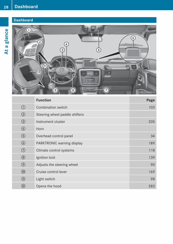
Dashboard
Function Page: Combination switch 103
; Steering wheel paddle shifters
= Instrument cluster 205
? Horn
A Overhead control panel 34
B PARKTRONIC warning display 189
C Climate control systems 118
D Ignition lock 139
E Adjusts the steering wheel 90
F Cruise control lever 169
G Light switch 98
H Opens the hood 283
28 DashboardAt
aglance
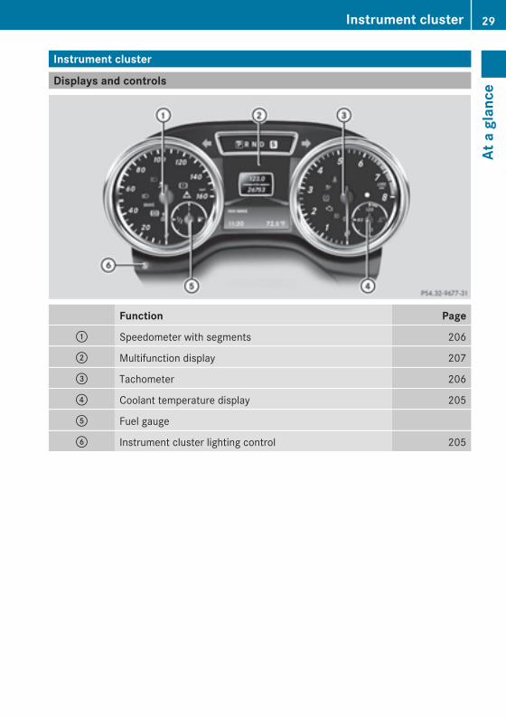
Instrument cluster
Displays and controls
Function Page: Speedometer with segments 206
; Multifunction display 207
= Tachometer 206
? Coolant temperature display 205
A Fuel gauge
B Instrument cluster lighting control 205
Instrument cluster 29
Ataglance
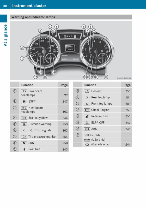
Warning and indicator lamps
Function Page: L Low-beam
headlamps 99
; ÷ ESP® 247
= K High-beamheadlamps 103
? J Brakes (yellow) 244
A · Distance warning 253
B #! Turn signals 103
C h Tire pressure monitor 254
D 6 SRS 250
E ü Seat belt 243
Function PageF ? Coolant 251
G R Rear fog lamp 101
H O Front fog lamps 101
I ; Check Engine 251
J 8 Reserve fuel 251
K å ESP® OFF 247
L ! ABS 245
M Brakes (red)$ (USA only)J (Canada only) 244
30 Instrument clusterAt
aglance
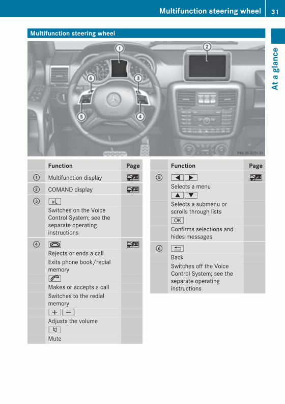
Multifunction steering wheel
Function Page: Multifunction display ~
; COMAND display ~
= ?
Switches on the VoiceControl System; see theseparate operatinginstructions
? ~ ~
Rejects or ends a callExits phone book/redialmemory6
Makes or accepts a callSwitches to the redialmemoryWX
Adjusts the volume8
Mute
Function PageA =; ~
Selects a menu9:
Selects a submenu orscrolls through listsa
Confirms selections andhides messages
B %
BackSwitches off the VoiceControl System; see theseparate operatinginstructions
Multifunction steering wheel 31
Ataglance
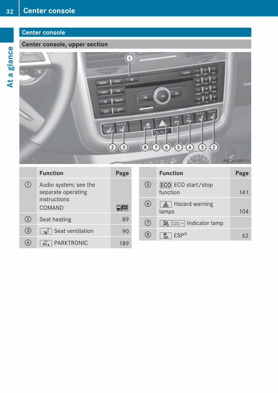
Center console
Center console, upper section
Function Page: Audio system; see the
separate operatinginstructionsCOMAND ~
; Seat heating 89
= s Seat ventilation 90
? c PARKTRONIC 189
Function PageA ¤ ECO start/stop
function 141
B £ Hazard warninglamps 104
C 45 Indicator lamp
D å ESP® 62
32 Center consoleAt
aglance
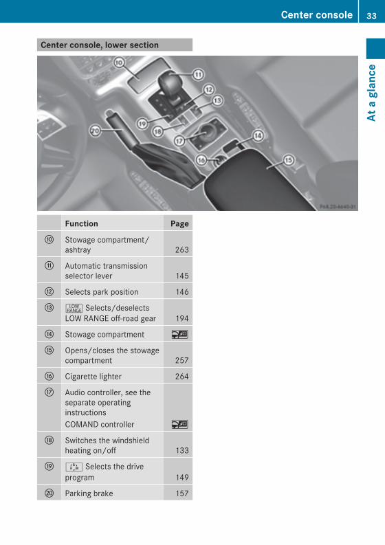
Center console, lower section
Function PageF Stowage compartment/
ashtray 263
G Automatic transmissionselector lever 145
H Selects park position 146
I + Selects/deselectsLOW RANGE off-road gear 194
J Stowage compartment ~
K Opens/closes the stowagecompartment 257
L Cigarette lighter 264
M Audio controller, see theseparate operatinginstructionsCOMAND controller ~
N Switches the windshieldheating on/off 133
O Ú Selects the driveprogram 149
P Parking brake 157
Center console 33
Ataglance
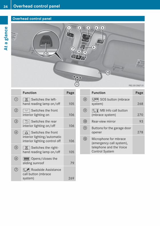
Overhead control panel
Function Page: p Switches the left-
hand reading lamp on/off 105
; c Switches the frontinterior lighting on 106
= u Switches the rearinterior lighting on/off 106
? | Switches the frontinterior lighting/automaticinterior lighting control off 106
A p Switches the right-hand reading lamp on/off 105
B ¡ Opens/closes thesliding sunroof 79
C F Roadside Assistancecall button (mbracesystem) 269
Function PageD G SOS button (mbrace
system) 268
E ï MB Info call button(mbrace system) 270
F Rear-view mirror 93
G Buttons for the garage dooropener 278
H Microphone for mbrace(emergency call system),telephone and the VoiceControl System
34 Overhead control panelAt
aglance
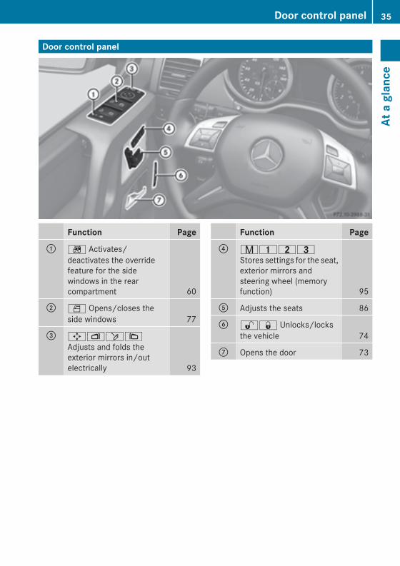
Door control panel
Function Page: n Activates/
deactivates the overridefeature for the sidewindows in the rearcompartment 60
; W Opens/closes theside windows 77
= 7Zö\Adjusts and folds theexterior mirrors in/outelectrically 93
Function Page? r45=
Stores settings for the seat,exterior mirrors andsteering wheel (memoryfunction) 95
A Adjusts the seats 86
B %& Unlocks/locksthe vehicle 74
C Opens the door 73
Door control panel 35
Ataglance

36

Useful information .............................. 38Panic alarm .......................................... 38Occupant safety .................................. 38Children in the vehicle ........................ 54Driving safety systems ....................... 60Theft deterrent locking system ......... 64
37
Safety
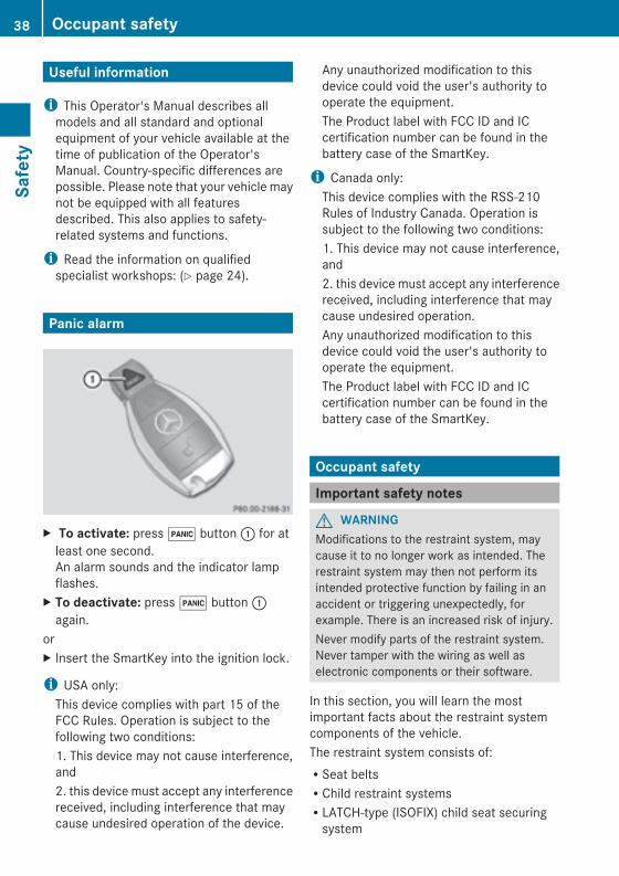
Useful information
i This Operator's Manual describes allmodels and all standard and optionalequipment of your vehicle available at thetime of publication of the Operator'sManual. Country-specific differences arepossible. Please note that your vehicle maynot be equipped with all featuresdescribed. This also applies to safety-related systems and functions.
i Read the information on qualifiedspecialist workshops: (Y page 24).
Panic alarm
X To activate: press! button: for atleast one second.An alarm sounds and the indicator lampflashes.
X To deactivate: press! button:again.
orX Insert the SmartKey into the ignition lock.
i USA only:This device complies with part 15 of theFCC Rules. Operation is subject to thefollowing two conditions:1. This device may not cause interference,and2. this device must accept any interferencereceived, including interference that maycause undesired operation of the device.
Any unauthorized modification to thisdevice could void the user's authority tooperate the equipment.The Product label with FCC ID and ICcertification number can be found in thebattery case of the SmartKey.
i Canada only:This device complies with the RSS-210Rules of Industry Canada. Operation issubject to the following two conditions:1. This device may not cause interference,and2. this device must accept any interferencereceived, including interference that maycause undesired operation.Any unauthorized modification to thisdevice could void the user's authority tooperate the equipment.The Product label with FCC ID and ICcertification number can be found in thebattery case of the SmartKey.
Occupant safety
Important safety notes
G WARNINGModifications to the restraint system, maycause it to no longer work as intended. Therestraint system may then not perform itsintended protective function by failing in anaccident or triggering unexpectedly, forexample. There is an increased risk of injury.Never modify parts of the restraint system.Never tamper with the wiring as well aselectronic components or their software.
In this section, you will learn the mostimportant facts about the restraint systemcomponents of the vehicle.The restraint system consists of:RSeat beltsRChild restraint systemsRLATCH-type (ISOFIX) child seat securingsystem
38 Occupant safetySafety
Additional protection is provided by:RSRS (Supplemental Restraint System)RNECK-PRO head restraintsRAir bag system components with:
- The 4 5 indicator lamp- Front-passenger seat with BabySmart™air bag deactivation system
Although the systems are independent, theirprotective functions work in conjunction witheach other. Not all air bags are alwaysdeployed in an accident.
i Observe the additional information oninfants and children traveling with you inthe vehicle and restraint systems forinfants and children (Y page 54).
SRS (Supplemental Restraint System)
IntroductionSRS reduces the risk of occupants cominginto contact with the vehicle's interior in theevent of an accident. It can also reduce theeffect of the forces to which occupants aresubjected during an accident.SRS consists of:RSRS warning lamps 6RAir bagsRAir bag control unit (with crash sensors)REmergency Tensioning Device (ETD) forseat beltsRSeat belt force limiter
SRS warning lampSRS functions are checked regularly whenyou switch on the ignition and when theengine is running. Therefore, malfunctionscan be detected in good time.The6 SRSwarning lamp in the instrumentcluster lights up when the ignition is switchedon. It goes out no later than a few secondsafter the engine is started.
The SRS components are in operationalreadiness when the 6 SRS indicator lampgoes out while the engine is running.
Safety guidelines for seat belts,Emergency Tensioning Devices (ETDs)and air bags
G WARNINGRDamaged seat belts or seat belts that havebeen subjected to stress in an accidentmust be replaced. Their anchoring pointsmust also be checked. Only use seat beltsinstalled or supplied by an authorizedMercedes-Benz Center.RAir bags and pyrotechnic EmergencyTensioning Devices (ETDs) containperchlorate material, which may requirespecial handling and regard for theenvironment. Check your national disposalguidelines. California residents, seewww.dtsc.ca.gov/HazardousWaste/Perchlorate/index.cfm.RAir bags and ETDs are designed to functionon a one-time-only basis. An air bag or ETDthat has deployed must be replaced.RDo not pass seat belts over sharp edges.They could tear.RDo not make any modification that couldchange the effectiveness of the seat belts.RDo not bleach or dye seat belts as this mayseverely weaken them. In a crash they maynot be able to provide adequate protection.RNo modifications of any kind may be madeto any components or wiring of the SRS.RDo not change or remove any componentor part of the SRS.RDo not install additional trim material, seatcovers, badges, etc. over the steeringwheel hub, front-passenger front air bagcover, outer sides of the seat backrests,door trim panels, or door frame trims.RDo not install additional electrical/electronic equipment on or near SRScomponents and wiring.
Occupant safety 39
Safety
Z
RKeep area between air bags and occupantsfree of objects (e.g. packages, purses,umbrellas, etc.).RDo not hang items such as coat hangersfrom the coat hooks or handles over thedoor. These items may be thrown around inthe vehicle and cause head and otherinjuries when the window curtain air bag isdeployed.RAir bag systemcomponentswill be hot afteran air bag has inflated. Do not touch them.RNever place your feet on the instrumentpanel, dashboard, or on the seat. Alwayskeep both feet on the floor in front of theseat.RImproper repair work on the SRS creates arisk of rendering the SRS inoperative orcausing unintended air bag deployment.Work on the SRS must therefore only beperformed by qualified technicians.Contact an authorized Mercedes-BenzCenter.RFor your protection and the protection ofothers, when scrapping the air bag unit orETD, our safety instructions must befollowed. These instructions are availablefrom any authorized Mercedes-BenzCenter.RGiven the considerable deployment speed,required inflation volume, and the materialof the air bags, there is the possibility ofabrasions or other, potentiallymore seriousinjuries resulting from air bag deployment.
If you sell your vehicle, Mercedes-Benzstrongly recommends that you inform thesubsequent owner that the vehicle isequipped with SRS. Also, refer them to theapplicable section in the Operator's Manual.
Air bags
Important safety notes
G WARNINGAir bags are designed to reduce the potentialof injury and fatality in certainRfrontal impacts (front air bags)Rside impacts (window curtain air bags)However, no system available today cancompletely eliminate injuries and fatalities.Deployment of the air bags temporarilyreleases a small amount of dust from the airbags. This dust, however, is neither harmfulto your health, nor does it indicate a fire in thevehicle. The dust might cause sometemporary breathing difficulty for people withasthma or other breathing trouble. To avoidthis, you may wish to get out of the vehicle assoon as it is safe to do so. If you have anybreathing difficulty but cannot get out of thevehicle after the air bag inflates, then get freshair by opening a window or door.
G WARNINGTo reduce the risk of injury when the front airbags inflate, it is very important for the driverand front passenger to always be in a properlyseated position and to wear their respectiveseat belt.For maximum protection in the event of acollision always be in normal seated positionwith your back against the seat backrest.Fasten your seat belt and make sure it isproperly positioned on your body.
40 Occupant safetySafety
Since the air bag inflates with considerablespeed and force, a proper seating positionand correct positioning of the hands on thesteering wheel will help to keep you at a safedistance from the air bag. Occupants who arenot wearing their seat belt, are not seatedproperly or are too close to the air bag can beseriously injured or killed by an air bag as itinflates with great force instantaneously:RSit with the seat belt properly fastened in aposition that is as upright as possible withyour back against the seat backrest.RMove the driver's seat as far back aspossible, still permitting proper operationof vehicle controls. The distance from thecenter of the driver's chest to the center ofthe air bag cover on the steering wheelmust be at least 10 inches (25 cm) or more.You should be able to accomplish this byadjusting the seat and steering wheel. Ifyou have any difficulties, please contact anauthorized Mercedes-Benz Center.RDo not lean your head or chest close to thesteering wheel or dashboard.RKeep hands on the outside of the steeringwheel rim. Placing hands and arms insidethe rim can increase the risk and potentialseverity of hand/arm injury when the driverfront air bag inflates.RAdjust the front passenger seat as far aspossible rearward from the dashboardwhen the seat is occupied.ROccupants, especially children, shouldnever place their bodies or lean their headsin the area of the door where the windowcurtain air bag inflates. This could result inserious injuries or death should the windowcurtain air bag be deployed. Always sit asupright as possible, wear the seat beltproperly and use an appropriately sizedinfant restraint, toddler restraint, orbooster seat recommended for the size andweight of the child.RChildren 12 years old and undermust neverride in the front seat, except in a Mercedes-Benz authorized BabySmart™ compatible
child seat, which operates with theBabySmart™ air bag deactivation systeminstalled in the vehicle to deactivate thefront passenger front air bag when it isinstalled properly. Otherwise they will bestruck by the air bag when it inflates in acrash. If this happens, serious or fatal injurywill result.
Failure to follow these instructions can resultin severe injuries to you or other occupants.If you sell your vehicle, it is important that youmake the buyer aware of this safetyinformation. Be sure to give the buyer thisOperator's Manual.
G WARNINGAccident research shows that the safest placefor children in an automobile is in a rear seat.Should you choose to place a child 12 yearsold or under in the front passenger seat ofyour vehicle, you must properly use aBabySmartTM child restraint which will turn offthe front passenger front air bag.To help avoid the possibility of injury, pleasefollow these guidelines:
(1) Always sit as upright as possible,wear the seat belt properly, and forchildren 12 years old and under,use an appropriately sized infantrestraint, toddler restraint, orbooster seat recommended for thesize and weight of the child.
(2) Always wear seat belts properly.
G WARNINGThe service life of the air bag is limited to 15years. After a maximum of 15 years, have theair bag replaced at a qualified specialistworkshop that has the necessary specialistknowledge and tools to carry out the workrequired. Mercedes-Benz recommends thatyou use an authorized Mercedes-Benz Centerfor this purpose.
Occupant safety 41
Safety
Z
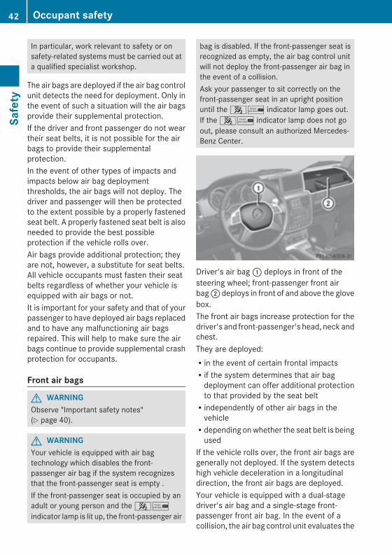
In particular, work relevant to safety or onsafety-related systems must be carried out ata qualified specialist workshop.
The air bags are deployed if the air bag controlunit detects the need for deployment. Only inthe event of such a situation will the air bagsprovide their supplemental protection.If the driver and front passenger do not weartheir seat belts, it is not possible for the airbags to provide their supplementalprotection.In the event of other types of impacts andimpacts below air bag deploymentthresholds, the air bags will not deploy. Thedriver and passenger will then be protectedto the extent possible by a properly fastenedseat belt. A properly fastened seat belt is alsoneeded to provide the best possibleprotection if the vehicle rolls over.Air bags provide additional protection; theyare not, however, a substitute for seat belts.All vehicle occupants must fasten their seatbelts regardless of whether your vehicle isequipped with air bags or not.It is important for your safety and that of yourpassenger to have deployed air bags replacedand to have any malfunctioning air bagsrepaired. This will help to make sure the airbags continue to provide supplemental crashprotection for occupants.
Front air bags
G WARNINGObserve "Important safety notes"(Y page 40).
G WARNINGYour vehicle is equipped with air bagtechnology which disables the front-passenger air bag if the system recognizesthat the front-passenger seat is empty .If the front-passenger seat is occupied by anadult or young person and the 4/indicator lamp is lit up, the front-passenger air
bag is disabled. If the front-passenger seat isrecognized as empty, the air bag control unitwill not deploy the front-passenger air bag inthe event of a collision.Ask your passenger to sit correctly on thefront-passenger seat in an upright positionuntil the 4/ indicator lamp goes out.If the 4/ indicator lamp does not goout, please consult an authorized Mercedes-Benz Center.
Driver's air bag: deploys in front of thesteering wheel; front-passenger front airbag; deploys in front of and above the glovebox.The front air bags increase protection for thedriver's and front-passenger's head, neck andchest.They are deployed:Rin the event of certain frontal impactsRif the system determines that air bagdeployment can offer additional protectionto that provided by the seat beltRindependently of other air bags in thevehicleRdepending onwhether the seat belt is beingused
If the vehicle rolls over, the front air bags aregenerally not deployed. If the system detectshigh vehicle deceleration in a longitudinaldirection, the front air bags are deployed.Your vehicle is equipped with a dual-stagedriver's air bag and a single-stage front-passenger front air bag. In the event of acollision, the air bag control unit evaluates the
42 Occupant safetySafety
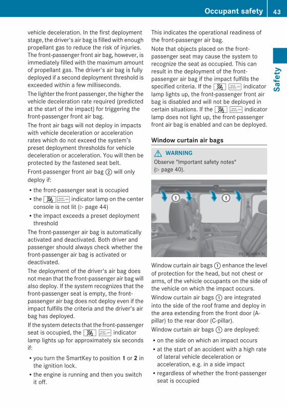
vehicle deceleration. In the first deploymentstage, the driver's air bag is filled with enoughpropellant gas to reduce the risk of injuries.The front-passenger front air bag, however, isimmediately filled with the maximum amountof propellant gas. The driver's air bag is fullydeployed if a second deployment threshold isexceeded within a few milliseconds.The lighter the front passenger, the higher thevehicle deceleration rate required (predictedat the start of the impact) for triggering thefront-passenger front air bag.The front air bags will not deploy in impactswith vehicle deceleration or accelerationrates which do not exceed the system’spreset deployment thresholds for vehicledeceleration or acceleration. You will then beprotected by the fastened seat belt.Front-passenger front air bag; will onlydeploy if:Rthe front-passenger seat is occupiedRthe 45 indicator lamp on the centerconsole is not lit (Y page 44)Rthe impact exceeds a preset deploymentthreshold
The front-passenger air bag is automaticallyactivated and deactivated. Both driver andpassenger should always check whether thefront-passenger air bag is activated ordeactivated.The deployment of the driver's air bag doesnot mean that the front-passenger air bag willalso deploy. If the system recognizes that thefront-passenger seat is empty, the front-passenger air bag does not deploy even if theimpact fulfills the criteria and the driver's airbag has deployed.If the systemdetects that the front-passengerseat is occupied, the 4 5 indicatorlamp lights up for approximately six secondsif:Ryou turn the SmartKey to position 1 or 2 inthe ignition lock.Rthe engine is running and then you switchit off.
This indicates the operational readiness ofthe front-passenger air bag.Note that objects placed on the front-passenger seat may cause the system torecognize the seat as occupied. This canresult in the deployment of the front-passenger air bag if the impact fulfills thespecified criteria. If the 4 5 indicatorlamp lights up, the front-passenger front airbag is disabled and will not be deployed incertain situations. If the 4 5 indicatorlamp does not light up, the front-passengerfront air bag is enabled and can be deployed.
Window curtain air bags
G WARNINGObserve "Important safety notes"(Y page 40).
Window curtain air bags: enhance the levelof protection for the head, but not chest orarms, of the vehicle occupants on the side ofthe vehicle on which the impact occurs.Window curtain air bags: are integratedinto the side of the roof frame and deploy inthe area extending from the front door (A-pillar) to the rear door (C-pillar).Window curtain air bags: are deployed:Ron the side on which an impact occursRat the start of an accident with a high rateof lateral vehicle deceleration oracceleration, e.g. in a side impactRregardless of whether the front-passengerseat is occupied
Occupant safety 43
Safety
Z
Rindependently of seat belt useRif the vehicle rolls over and the systemdetermines that window curtain air bagdeployment can offer additional protectionto that provided by the seat beltRindependently of the front air bagsWindow curtain air bags will not deploy inimpacts which do not exceed the system'spreset deployment thresholds for lateralacceleration/deceleration. You will then beprotected by the fastened seat belt.
BabySmart™ air bag deactivationsystem
How the air bag deactivation systemworks
G WARNINGAccording to accident statistics, children aresafer when properly restrained in the rearseating positions than in the front seatingposition. Thus, we strongly recommend thatchildren be placed in the rear seats wheneverpossible. Regardless of seating position,children 12 years old and under must beseated and properly secured in an appropriateinfant restraint, toddler restraint, or boosterseat recommended for the size and weight ofthe child.The infant or child restraint must be properlysecured with the vehicle's seat belt, the seatbelt and top tether strap, or lower anchors andtop tether strap, fully in accordance with thechild seat manufacturer's instructions.Occupants, especially children, should alwayssit as upright as possible, wear the seat beltproperly and use an appropriately sized infantrestraint, toddler restraint, or booster seatrecommended for the size and weight of thechild.
Children can be killed or seriously injured byan inflating air bag. Note the followingimportant information when circumstancesrequire you to place a child in the frontpassenger seat:RChildren 12 years old and undermust neverride in the front seat, except in a Mercedes-Benz authorized BabySmart™ compatiblechild seat, which operates with theBabySmart™ system installed in the vehicleto deactivate the front passenger front airbag when it is installed properly. Otherwisethey will be struck by the air bag when itinflates in a crash. If this happens, seriousor fatal injury will result.RA child in a rear-facing child restraint on thefront passenger seat will be seriouslyinjured or even killed if the front passengerfront air bag inflates in a collision whichcould occur under some circumstances,even with the air bag technology installedin your vehicle. The only means tocompletely eliminate this risk is to neverplace a child in a rear-facing child restraintin the front seat. We therefore stronglyrecommend that you always place a childin a rear-facing child restraint in a backseat.RIf you must install a BabySmart™compatible rear-facing child restraint onthe front passenger seat becausecircumstances require you to do so, makesure the 4 / indicator lamp isilluminated, indicating that the frontpassenger front air bag is deactivated.Should the 4 / indicator lamp notilluminate or go out while the restraint isinstalled, please check installation.Periodically check the 4 / indicatorlamp while driving to make sure the4 / indicator lamp is illuminated. Ifthe 4 / indicator lamp goes out orremains out, do not transport a child on thefront passenger seat until the system hasbeen repaired.A child in a rear-facing child restraint on thefront passenger seat will be seriously
44 Occupant safetySafety
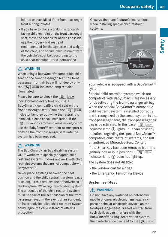
injured or even killed if the front passengerfront air bag inflates.RIf you have to place a child in a forward-facing child restraint on the front passengerseat, move the seat as far back as possible,use the proper child restraintrecommended for the age, size and weightof the child, and secure child restraint withthe vehicle's seat belt according to thechild seat manufacturer's instructions.
G WARNINGWhen using a BabySmart™ compatible childseat on the front passenger seat, the frontpassenger front air bag will not deploy only ifthe 4 / indicator lamp remainsilluminated.Please be sure to check the 4 /indicator lamp every time you use aBabySmart™ compatible child seat on thefront passenger seat. Should the 4 /indicator lamp go out while the restraint isinstalled, please check installation. If the4 / indicator lamp remains out, do notuse the BabySmart™ restraint to transport achild on the front passenger seat until thesystem has been repaired.
G WARNINGThe BabySmart™ air bag disabling systemONLY works with specially adapted childrestraint systems. It does not work with childrestraint systems that are not compatiblewithBabySmart™.Never place anything between the seatcushion and the child restraint system (e.g. acushion), as this reduces the effectiveness ofthe BabySmart™ air bag deactivation system.The underside of the child restraint systemmust lie against the seat cushion of the front-passenger seat. In the event of an accident,an incorrectly installed child restraint systemcould injure the child instead of offeringprotection.
Observe the manufacturer's instructionswhen installing special child restraintsystems.
Your vehicle is equipped with a BabySmart™system.Special child restraint systems which arecompatible with BabySmart™ are necessaryfor deactivating the front-passenger air bag.When the special BabySmart™-compatiblechild restraint system is installed correctlyand is recognized by the sensor system in thefront-passenger seat, the front-passenger airbag is deactivated. In this case, 45indicator lamp: lights up. If you have anyquestions regarding the special BabySmart™-compatible child restraint systems, consultan authorized Mercedes-Benz Center.If the SmartKey has been removed from theignition lock or is in position 0, 45indicator lamp: does not light up.The system does not disable:Rthe window curtain air bagRthe Emergency Tensioning Device
System self-test
G WARNINGDo not leave any switched on notebooks,mobile phones, electronic tags (e.g. a skipass) or similar electronic devices on thefront-passenger seat. Signals emitted fromsuch devices can interfere with theBabySmart™ air bag deactivation system.Such interference can lead to the 45
Occupant safety 45
Safety
Z
indicator lamp not lighting up during the self-test.If the + SRS warning lamp and the4/ indicator lamp light upsimultaneously in the instrument cluster, thesystem is malfunctioning. The front-passenger air bag could deploywithout cause,or may fail to deploy in the event of anaccident.Have the system checked as soon as possibleat an authorized Mercedes-Benz Center.
The 45 indicator lamp lights up whenthe SmartKey is turned to position 1 or 2 inthe ignition lock.The 45 indicator lamp goes out afterapproximately six seconds.If the 45 indicator lamp does not lightup or is always lit, then the system ismalfunctioning. Have the BabySmart™system checked at an authorized Mercedes-Benz Center before transporting a child onthe front-passenger seat.For further information, see "Problems withair bag deactivation system" (Y page 47).
46 Occupant safetySafety
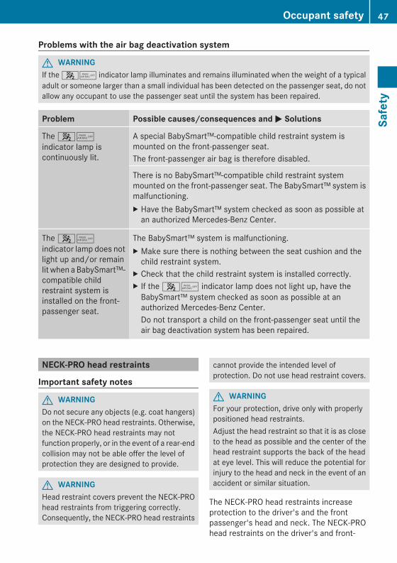
Problems with the air bag deactivation system
G WARNINGIf the 45 indicator lamp illuminates and remains illuminated when the weight of a typicaladult or someone larger than a small individual has been detected on the passenger seat, do notallow any occupant to use the passenger seat until the system has been repaired.
Problem Possible causes/consequences andMM Solutions
The 45indicator lamp iscontinuously lit.
A special BabySmart™-compatible child restraint system ismounted on the front-passenger seat.The front-passenger air bag is therefore disabled.
There is no BabySmart™-compatible child restraint systemmounted on the front-passenger seat. The BabySmart™ system ismalfunctioning.X Have the BabySmart™ system checked as soon as possible atan authorized Mercedes-Benz Center.
The 45indicator lamp does notlight up and/or remainlit when a BabySmart™-compatible childrestraint system isinstalled on the front-passenger seat.
The BabySmart™ system is malfunctioning.X Make sure there is nothing between the seat cushion and thechild restraint system.
X Check that the child restraint system is installed correctly.X If the 45 indicator lamp does not light up, have theBabySmart™ system checked as soon as possible at anauthorized Mercedes-Benz Center.Do not transport a child on the front-passenger seat until theair bag deactivation system has been repaired.
NECK-PRO head restraints
Important safety notes
G WARNINGDo not secure any objects (e.g. coat hangers)on the NECK-PRO head restraints. Otherwise,the NECK-PRO head restraints may notfunction properly, or in the event of a rear-endcollision may not be able offer the level ofprotection they are designed to provide.
G WARNINGHead restraint covers prevent the NECK-PROhead restraints from triggering correctly.Consequently, the NECK-PRO head restraints
cannot provide the intended level ofprotection. Do not use head restraint covers.
G WARNINGFor your protection, drive only with properlypositioned head restraints.Adjust the head restraint so that it is as closeto the head as possible and the center of thehead restraint supports the back of the headat eye level. This will reduce the potential forinjury to the head and neck in the event of anaccident or similar situation.
The NECK-PRO head restraints increaseprotection to the driver's and the frontpassenger's head and neck. The NECK-PROhead restraints on the driver's and front-
Occupant safety 47
Safety
Z
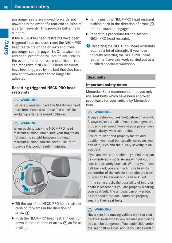
passenger seats are moved forwards andupwards in the event of a rear-end collision ofa certain severity. This provides better headsupport.If the NECK-PRO head restraints have beentriggered in an accident, reset the NECK-PROhead restraints on the driver’s and front-passenger seat (Y page 48). Otherwise, theadditional protection will not be available inthe event of another rear-end collision. Youcan recognize if NECK-PRO head restraintshave been triggered by the fact that they havemoved forwards and can no longer beadjusted.
Resetting triggered NECK-PRO headrestraints
G WARNINGFor safety reasons, have the NECK-PRO headrestraints checked at a qualified specialistworkshop after a rear-end collision.
G WARNINGWhen pushing back the NECK-PRO headrestraint cushion, make sure your fingers donot become caught between the headrestraint cushion and the cover. Failure toobserve this could result in injuries.
X Tilt the top of the NECK-PRO head restraintcushion forwards in the direction ofarrow:.
X Push the NECK-PRO head restraint cushiondown in the direction of arrow; as far asit will go.
X Firmly push the NECK-PRO head restraintcushion back in the direction of arrow=until the cushion engages.
X Repeat this procedure for the secondNECK-PRO head restraint.
i Resetting the NECK-PRO head restraintsrequires a lot of strength. If you havedifficulty resetting the NECK-PRO headrestraints, have this work carried out at aqualified specialist workshop.
Seat belts
Important safety notesMercedes-Benz recommends that you onlyuse seat belts which have been approvedspecifically for your vehicle by Mercedes-Benz.
G WARNINGAlways fasten your seat belt before driving off.Always make sure all of your passengers areproperly restrained. You and your passengersshould always wear seat belts.Failure to wear and properly fasten andposition your seat belt greatly increases yourrisk of injuries and their likely severity in anaccident.If you are ever in an accident, your injuries canbe considerably more severe without yourseat belt properly buckled. Without your seatbelt buckled, you are much more likely to hitthe interior of the vehicle or be ejected fromit. You can be seriously injured or killed.In the same crash, the possibility of injury ordeath is lessened if you are properly wearingyour seat belt. The air bags can only protectas intended if the occupants are properlywearing their seat belts.
G WARNINGNever ride in a moving vehicle with the seatbackrest in an excessively reclined position asthis can be dangerous. You could slide underthe seat belt in a collision. If you slide under
48 Occupant safetySafety
it, the seat belt would apply force at theabdomen or neck. That could cause seriousor even fatal injuries. The seat backrest andseat belt provide the best restraint when thewearer is in a position that is as upright aspossible and the seat belt is properlypositioned on the body.
G WARNINGNever let more people ride in the vehicle thanthere are seat belts available. Make sureeveryone riding in the vehicle is correctlyrestrained with a separate seat belt. Neveruse a seat belt for more than one person at atime.
G WARNINGAlways have damaged seat belts or seat beltsthat have been subjected to a load in anaccident replaced and the anchorageschecked.Only use seat belts that have been approvedby Mercedes-Benz.Never tamper with seat belts. This can resultin the unintended deployment of theEmergency Tensioning Devices or the failureto deploy when necessary.Do not bleach or dye seat belts, as this mayseverely weaken them. In the event of acollision, they may be unable to provideadequate protection.Have all work carried out only by qualifiedtechnicians. Consult a qualified specialistworkshop.
The use of infant or child restraints is requiredby law in all 50 states, the District ofColumbia, all U.S. territories and all Canadianprovinces.Even where this is not the case, all vehicleoccupants should have their seat beltsfastened when the vehicle is in motion.
i See "Children in the vehicle"(Y page 54) for further information oninfants and children traveling in the vehicle,as well as on child restraint systems.
Correct use of the seat belts
G WARNINGCORRECT USE OF SEAT BELTSRSeat belts only work properly if they arefastened correctly. Never wear seat belts inany other way than as described in thissection, as that could result in seriousinjuries in the event of an accident.RAll occupants should wear their seat belt atall times, because seat belts help reducethe likelihood of and potential severity ofinjuries in accidents, even if the vehicleoverturns. The restraint system installed isequipped with SRS (driver's air bag, front-passenger air bag, window curtain airbags), belt tensioners and belt forcelimiters.The system is designed to enhance theprotection offered to occupants who arewearing their seat belts correctly, in certainfrontal impacts (front air bags and belttensioners) and side impacts (windowcurtain air bags and belt tensioners) whichexceed preset deployment thresholds.RNever route the shoulder section of theseat belt under your arm, across your neckor anywhere other than across yourshoulder. In the event of a frontal impact,your body would be moved too far forward.This would increase the risk of head andneck injuries. The seat belt would thenapply excessive force to the ribs orabdomen which could cause severeinternal injuries to organs such as the liveror spleen.Adjust the seat belt so that the upper partof the belt is as close as possible to thecenter of the shoulder. It should not touchthe neck. Never route the belt under theshoulder. The height of the belt outlet canbe altered to ensure correct usage.RThe lap belt should be routed as low aspossible across the hips, not across theabdomen. If the lap belt is routed across the
Occupant safety 49
Safety
Z
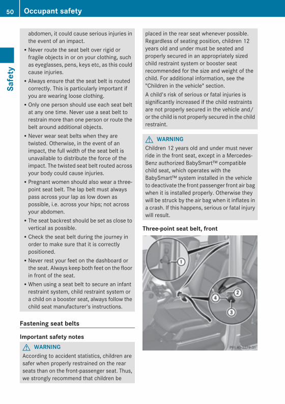
abdomen, it could cause serious injuries inthe event of an impact.RNever route the seat belt over rigid orfragile objects in or on your clothing, suchas eyeglasses, pens, keys etc, as this couldcause injuries.RAlways ensure that the seat belt is routedcorrectly. This is particularly important ifyou are wearing loose clothing.ROnly one person should use each seat beltat any one time. Never use a seat belt torestrain more than one person or route thebelt around additional objects.RNever wear seat belts when they aretwisted. Otherwise, in the event of animpact, the full width of the seat belt isunavailable to distribute the force of theimpact. The twisted seat belt routed acrossyour body could cause injuries.RPregnant women should also wear a three-point seat belt. The lap belt must alwayspass across your lap as low down aspossible, i.e. across your hips; not acrossyour abdomen.RThe seat backrest should be set as close tovertical as possible.RCheck the seat belt during the journey inorder to make sure that it is correctlypositioned.RNever rest your feet on the dashboard orthe seat. Always keep both feet on the floorin front of the seat.RWhen using a seat belt to secure an infantrestraint system, child restraint system ora child on a booster seat, always follow thechild seat manufacturer's instructions.
Fastening seat belts
Important safety notesG WARNINGAccording to accident statistics, children aresafer when properly restrained on the rearseats than on the front-passenger seat. Thus,we strongly recommend that children be
placed in the rear seat whenever possible.Regardless of seating position, children 12years old and under must be seated andproperly secured in an appropriately sizedchild restraint system or booster seatrecommended for the size and weight of thechild. For additional information, see the"Children in the vehicle" section.A child's risk of serious or fatal injuries issignificantly increased if the child restraintsare not properly secured in the vehicle and/or the child is not properly secured in the childrestraint.
G WARNINGChildren 12 years old and under must neverride in the front seat, except in a Mercedes-Benz authorized BabySmart™ compatiblechild seat, which operates with theBabySmart™ system installed in the vehicleto deactivate the front passenger front air bagwhen it is installed properly. Otherwise theywill be struck by the air bag when it inflates ina crash. If this happens, serious or fatal injurywill result.
Three-point seat belt, front
50 Occupant safetySafety
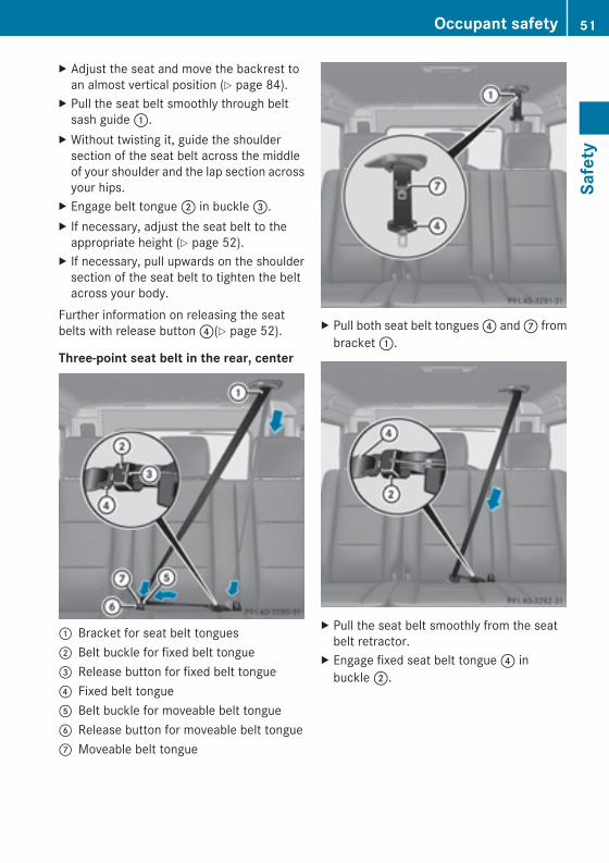
X Adjust the seat and move the backrest toan almost vertical position (Y page 84).
X Pull the seat belt smoothly through beltsash guide:.
X Without twisting it, guide the shouldersection of the seat belt across the middleof your shoulder and the lap section acrossyour hips.
X Engage belt tongue; in buckle=.X If necessary, adjust the seat belt to theappropriate height (Y page 52).
X If necessary, pull upwards on the shouldersection of the seat belt to tighten the beltacross your body.
Further information on releasing the seatbelts with release button?(Y page 52).
Three-point seat belt in the rear, center
: Bracket for seat belt tongues; Belt buckle for fixed belt tongue= Release button for fixed belt tongue? Fixed belt tongueA Belt buckle for moveable belt tongueB Release button for moveable belt tongueC Moveable belt tongue
X Pull both seat belt tongues? andC frombracket:.
X Pull the seat belt smoothly from the seatbelt retractor.
X Engage fixed seat belt tongue? inbuckle;.
Occupant safety 51
Safety
Z
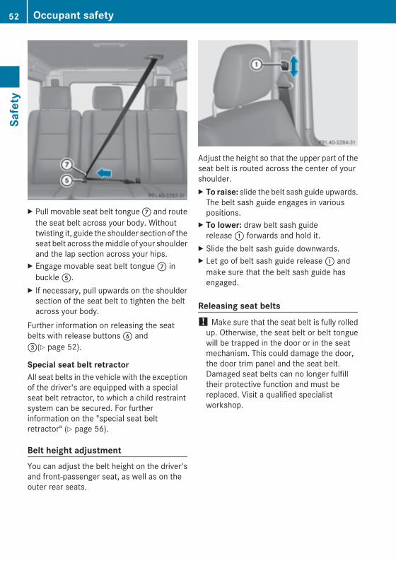
X Pull movable seat belt tongueC and routethe seat belt across your body. Withouttwisting it, guide the shoulder section of theseat belt across themiddle of your shoulderand the lap section across your hips.
X Engage movable seat belt tongueC inbuckleA.
X If necessary, pull upwards on the shouldersection of the seat belt to tighten the beltacross your body.
Further information on releasing the seatbelts with release buttonsB and=(Y page 52).
Special seat belt retractorAll seat belts in the vehicle with the exceptionof the driver's are equipped with a specialseat belt retractor, to which a child restraintsystem can be secured. For furtherinformation on the "special seat beltretractor" (Y page 56).
Belt height adjustmentYou can adjust the belt height on the driver'sand front-passenger seat, as well as on theouter rear seats.
Adjust the height so that the upper part of theseat belt is routed across the center of yourshoulder.X To raise: slide the belt sash guide upwards.The belt sash guide engages in variouspositions.
X To lower: draw belt sash guiderelease: forwards and hold it.
X Slide the belt sash guide downwards.X Let go of belt sash guide release: andmake sure that the belt sash guide hasengaged.
Releasing seat belts! Make sure that the seat belt is fully rolledup. Otherwise, the seat belt or belt tonguewill be trapped in the door or in the seatmechanism. This could damage the door,the door trim panel and the seat belt.Damaged seat belts can no longer fulfilltheir protective function and must bereplaced. Visit a qualified specialistworkshop.
52 Occupant safetySafety
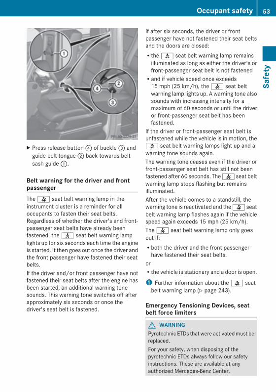
X Press release button? of buckle= andguide belt tongue; back towards beltsash guide:.
Belt warning for the driver and frontpassengerThe 7 seat belt warning lamp in theinstrument cluster is a reminder for alloccupants to fasten their seat belts.Regardless of whether the driver's and front-passenger seat belts have already beenfastened, the 7 seat belt warning lamplights up for six seconds each time the engineis started. It then goes out once the driver andthe front passenger have fastened their seatbelts.If the driver and/or front passenger have notfastened their seat belts after the engine hasbeen started, an additional warning tonesounds. This warning tone switches off afterapproximately six seconds or once thedriver's seat belt is fastened.
If after six seconds, the driver or frontpassenger have not fastened their seat beltsand the doors are closed:Rthe 7 seat belt warning lamp remainsilluminated as long as either the driver's orfront-passenger seat belt is not fastenedRand if vehicle speed once exceeds15 mph (25 km/h), the 7 seat beltwarning lamp lights up. A warning tone alsosounds with increasing intensity for amaximum of 60 seconds or until the driveror front-passenger seat belt has beenfastened.
If the driver or front-passenger seat belt isunfastened while the vehicle is in motion, the7 seat belt warning lamps light up and awarning tone sounds again.The warning tone ceases even if the driver orfront-passenger seat belt has still not beenfastened after 60 seconds. The7 seat beltwarning lamp stops flashing but remainsilluminated.After the vehicle comes to a standstill, thewarning tone is reactivated and the7 seatbelt warning lamp flashes again if the vehiclespeed again exceeds 15 mph (25 km/h).The 7 seat belt warning lamp only goesout if:Rboth the driver and the front passengerhave fastened their seat belts.
orRthe vehicle is stationary and a door is open.
i Further information about the 7 seatbelt warning lamp (Y page 243).
Emergency Tensioning Devices, seatbelt force limiters
G WARNINGPyrotechnic ETDs that were activatedmust bereplaced.For your safety, when disposing of thepyrotechnic ETDs always follow our safetyinstructions. These are available at anyauthorized Mercedes-Benz Center.
Occupant safety 53
Safety
Z

! If the co-driver's seat is unoccupied, donot insert the belt tongue into the buckle ofthe co-driver's seat. This may otherwiselead to the triggering of the EmergencyTensioning Device in the event of anaccident, which will then need to bereplaced.
X In order to ensure that the pyrotechnicEmergency Tensioning Devices have notbeen triggered, always have the seat beltschecked after an accident.If the Emergency Tensioning Devices havebeen triggered, they must be replaced.
The seat belts for the front seats and rearouter seats are equipped with EmergencyTensioning Devices and seat belt forcelimiters.The ETDs on the driver's and front-passengerseat consist of pyrotechnic belt buckletensioners and belt anchor installationtensioners that are triggered together. Thebelt buckle tensioner is mounted on the B-pillar and the belt anchor installation ismounted on the side of the seat. Afterdeploying, both tensioners must always bereplaced.The ETDs tighten the seat belts in an accident,pulling them close against the body.The ETDs do not correct incorrect seatpositions or incorrectly fastened seat belts.The ETDs do not pull vehicle occupants backtowards the backrest.Seat belt force limiters, when activated, areemployed to help reduce the peak forceexerted by the seat belts on occupants duringa crash.The front seat belt force limiters aresynchronized with the front air bags, whichtake on a part of the deceleration force. Thus,the force exerted on the occupant isdistributed over a greater area.
The ETDs can only be activated when:Rthe SmartKey is in position 1 or 2 in theignition lock.Rthe restraint systems are operational; see"SRS warning lamp" (Y page 39).Rthe belt tongue is engaged in the buckle oneach of the lap-shoulder belts in the frontRthe front-passenger seat is occupied andthe belt tongue is engaged in the buckle onthe front-passenger side
The Emergency Tensioning Devices aretriggered depending on the type and severityof an accident, if:Rin the event of a head-on or rear-endcollision, the vehicle decelerates oraccelerates rapidly in a longitudinaldirection during the initial stages of theimpactRin the event of a side impact, on the sideopposite the impact the vehicledecelerates or accelerates rapidly in alateral directionRin certain situations where the vehicle rollsover, the system determines that it canprovide additional protection
If the ETDs are deployed, you will hear a bang,and a small amount of powder may also bereleased. Only in rare cases will the bangaffect your hearing. The powder that isreleased generally does not constitute ahealth hazard. The 6 SRS warning lamplights up.
Children in the vehicle
Child restraint systems
Important safety notes
G WARNINGAccording to accident statistics, children aresafer when properly restrained in the rearseating positions than in the front seatingposition. Thus, we strongly recommend thatchildren be placed in the rear seats whenever
54 Children in the vehicleSafety
possible. Regardless of seating position,children 12 years old and under must beseated and properly secured in an appropriateinfant restraint, toddler restraint, or boosterseat recommended for the size and weight ofthe child.The infant or child restraint must be properlysecured with the vehicle's seat belt, the seatbelt and top tether strap, or lower anchors andtop tether strap, fully in accordance with thechild seat manufacturer's instructions.Occupants, especially children, should alwayssit as upright as possible, wear the seat beltproperly and use an appropriately sized infantrestraint, toddler restraint, or booster seatrecommended for the size and weight of thechild.Children can be killed or seriously injured byan inflating air bag. Note the followingimportant information when circumstancesrequire you to place a child in the frontpassenger seat:RChildren 12 years old and undermust neverride in the front seat, except in a Mercedes-Benz authorized BabySmart™ compatiblechild seat, which operates with theBabySmart™ system installed in the vehicleto deactivate the front passenger front airbag when it is installed properly. Otherwisethey will be struck by the air bag when itinflates in a crash. If this happens, seriousor fatal injury will result.RA child in a rear-facing child restraint on thefront passenger seat will be seriouslyinjured or even killed if the front passengerfront air bag inflates in a collision whichcould occur under some circumstances,even with the air bag technology installedin your vehicle. The only means tocompletely eliminate this risk is to neverplace a child in a rear-facing child restraintin the front seat. We therefore stronglyrecommend that you always place a childin a rear-facing child restraint in a backseat.RIf you must install a rear-facing childrestraint on the front passenger seat
because circumstances require you to doso, make sure the 4 / indicatorlamp is illuminated, indicating that the frontpassenger front air bag is deactivated.Should the 4 / indicator lamp notilluminate or go out while the restraint isinstalled, please check installation.Periodically check the 4 / indicatorlamp while driving to make sure the4 / indicator lamp is illuminated. Ifthe 4 / indicator lamp goes out orremains out, do not transport a child on thefront passenger seat until the system hasbeen repaired.A child in a rear-facing child restraint on thefront passenger seat will be seriouslyinjured or even killed if the front passengerfront air bag inflates.RIf you have to place a child in a forward-facing child restraint on the front passengerseat, move the seat as far back as possible,use the proper child restraintrecommended for the age, size and weightof the child, and secure child restraint withthe vehicle's seat belt according to thechild seat manufacturer's instructions.
G WARNINGInfants and small children should never sharea seat belt with another occupant. In the eventof an accident, they could be crushedbetween the occupant and seat belt.A child's risk of serious or fatal injuries issignificantly increased if the child restraintsare not properly secured in the vehicle and/or the child is not properly secured in the childrestraint.Children that are too large for a child restraintmust travel in seats using normal seat belts.Position the shoulder belt across the chestand shoulder, not the face or neck. A boosterseat may be necessary to achieve proper seatbelt positioning for children over 41 lbs(18 kg) until they reach a height where a lap/shoulder belt fits properly without a boosterseat.
Children in the vehicle 55
Safety
Z
When the child restraint is not in use, removeit from the vehicle or secure it with the seatbelt to prevent the child restraint frombecoming a projectile in the event of anaccident.
G WARNINGWhen leaving the vehicle, always remove theSmartKey from the ignition lock. Always takethe SmartKey with you and lock the vehicle.Do not leave children unattended in thevehicle, even if they are secured in a childrestraint system, or with access to anunlocked vehicle. A child's unsupervisedaccess to a vehicle could result in an accidentand/or serious personal injury. The childrencould:Rinjure themselves on parts of the vehicleRbe seriously or fatally injured throughexcessive exposure to extreme heat or coldRinjure themselves or cause an accidentwithvehicle equipment that can be operatedeven if the SmartKey is removed from theignition lock or removed from the vehicle,such as seat adjustment, steering wheeladjustment, or the memory function
If children open a door, they could injure otherpersons or get out of the vehicle and injurethemselves or be injured by following traffic.Do not expose the child restraint system todirect sunlight. The child restraint system'smetal parts, for example, could become veryhot, and the child could be burned on theseparts.
G WARNINGDo not carry heavy or hard objects in thepassenger compartment or trunk unless theyare firmly secured in place.Unsecured or improperly positioned cargoincreases a child's risk of injury in the eventofRstrong braking maneuversRsudden changes of directionRan accident
We recommend that all infants and childrenbe properly restrained using the infant orchild restraint systems at all times while thevehicle is in motion.Always use a child restraint system that iscompatible with BabySmart™ on the front-passenger seat.The use of infant or child restraints is requiredby law in all 50 states, the District ofColumbia, all U.S. territories and all Canadianprovinces.Infants and small children must be seated inan appropriate infant or child restraint systemrecommended for the size and weight of thechild. The infant or child restraint systemmust be properly secured in accordance withthe manufacturer's instructions. All infant orchild restraint systems must comply with theU.S. Federal Motor Vehicle Safety Standards213 and 225 and Canadian Motor VehicleSafety Standards 213 and 210.2.Confirmation that the child restraint systemcorresponds to the standards can be foundon an instruction label on the child restraintsystem. This confirmation can also be foundin the installation instructions that areincluded with the child restraint system.Always read and follow the manufacturer'sinstructions when using an infant or childrestraint system or booster seat.Observe the warning labels in the vehicleinterior or on the infant or child restraint.If an infant or child is traveling in the vehicle:X Secure the child with a child or infant seatrestraint system appropriate to the age andweight of the child.
X Make sure that the infant or child isproperly secured at all times while thevehicle is in motion.
Special seat belt retractor
G WARNINGObserve "Important safety notes"(Y page 54).
56 Children in the vehicleSafety
G WARNINGNever release the seat belt buckle while thevehicle is inmotion, since the special seat beltretractor will be deactivated.
All seat belts except the driver's seat belt areequipped with a special seat belt retractor.When activated, the special seat beltretractor ensures that the seat belt will notslacken once the child restraint system hasbeen secured.Installing a child restraint system:X Always comply with the manufacturer'sinstallation instructions.
X Pull the seat belt smoothly from the seatbelt retractor.
X Engage the seat belt tongue in the beltbuckle.
Activating the special seat belt retractor:X Pull the seat belt out fully and let the seatbelt retractor retract it again.While the seat belt is retracting, you shouldhear a ratcheting sound. The special seatbelt retractor is activated.
X Push down on the child restraint system totake up any slack.
Removing a child restraint system/deactivating the special seat belt retractor:X Always comply with the manufacturer'sinstallation instructions.
X Press the release button on the seat beltbuckle.
X Guide the seat belt tongue into the beltoutlet.The special seat belt retractor isdeactivated.
LATCH-type (ISOFIX) child seat anchorsin the rear
G WARNINGObserve "Important safety notes"(Y page 54).
G WARNINGChildren that are too large for a child restraintmust travel in seats using normal seat belts.Position shoulder belt across the chest andshoulder, not face or neck.A booster seat may be necessary to achieveproper seat belt positioning for children over41 lb (18 kg) until they reach a height wherea lap/shoulder belt fits properly without abooster.Install the child restraint system inaccordance with the manufacturer'sinstructions.Attach the child restraint system to bothsecuring rings.An incorrectly installed child restraint systemcould come loose during an accident andseriously or even fatally injure the child.Child restraint systems or child seat securingrings that are malfunctioning or damaged asthe result of a collision must be replaced.
! When installing the child restraint system,make sure that the seat belt for the middleseat does not get trapped. The seat beltcould otherwise be damaged.
LATCH-type (ISOFIX) is a standardizedsecuring system for specially designed childrestraint systems on the rear seats. Securingrings for two LATCH-type (ISOFIX) childrestraint systems are installed on the left andright of the rear seats.Before every trip, make sure that the LATCH-type (ISOFIX) child restraint system isengaged correctly in both securing ringsSecure non-LATCH-type (ISOFIX) childrestraint systems using the vehicle's seat beltsystem. Install the child seat according to themanufacturer's instructions.
Children in the vehicle 57
Safety
Z
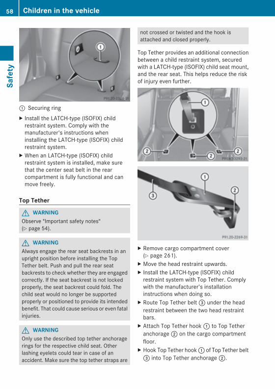
: Securing ringX Install the LATCH-type (ISOFIX) childrestraint system. Comply with themanufacturer's instructions wheninstalling the LATCH-type (ISOFIX) childrestraint system.
X When an LATCH-type (ISOFIX) childrestraint system is installed, make surethat the center seat belt in the rearcompartment is fully functional and canmove freely.
Top Tether
G WARNINGObserve "Important safety notes"(Y page 54).
G WARNINGAlways engage the rear seat backrests in anupright position before installing the TopTether belt. Push and pull the rear seatbackrests to check whether they are engagedcorrectly. If the seat backrest is not lockedproperly, the seat backrest could fold. Thechild seat would no longer be supportedproperly or positioned to provide its intendedbenefit. That could cause serious or even fatalinjuries.
G WARNINGOnly use the described top tether anchoragerings for the respective child seat. Otherlashing eyelets could tear in case of anaccident. Make sure the top tether straps are
not crossed or twisted and the hook isattached and closed properly.
Top Tether provides an additional connectionbetween a child restraint system, securedwith a LATCH-type (ISOFIX) child seat mount,and the rear seat. This helps reduce the riskof injury even further.
X Remove cargo compartment cover(Y page 261).
X Move the head restraint upwards.X Install the LATCH-type (ISOFIX) childrestraint system with Top Tether. Complywith the manufacturer's installationinstructions when doing so.
X Route Top Tether belt= under the headrestraint between the two head restraintbars.
X Attach Top Tether hook: to Top Tetheranchorage; on the cargo compartmentfloor.
X Hook Top Tether hook: of Top Tether belt= into Top Tether anchorage;.
58 Children in the vehicleSafety
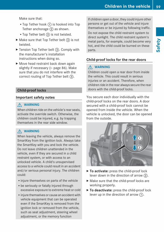
Make sure that:RTop Tether hook: is hooked into TopTether anchorage; as shown.RTop Tether belt= is not twisted.
X Make sure that Top Tether belt= is nottwisted.
X Tension Top Tether belt=. Comply withthe manufacturer's installationinstructions when doing so.
X Move head restraint back down againslightly if necessary (Y page 86). Makesure that you do not interfere with thecorrect routing of Top Tether belt=.
Child-proof locks
Important safety notes
G WARNINGWhen children ride on the vehicle's rear seats,activate the override switch. Otherwise, thechildren could be injured, e.g. by trappingthemselves in the rear side window.
G WARNINGWhen leaving the vehicle, always remove theSmartKey from the ignition lock. Always takethe SmartKey with you and lock the vehicle.Do not leave children unattended in thevehicle, even if they are secured in a childrestraint system, or with access to anunlocked vehicle. A child's unsupervisedaccess to a vehicle could result in an accidentand/or serious personal injury. The childrencould:Rinjure themselves on parts of the vehicleRbe seriously or fatally injured throughexcessive exposure to extreme heat or coldRinjure themselves or cause an accidentwithvehicle equipment that can be operatedeven if the SmartKey is removed from theignition lock or removed from the vehicle,such as seat adjustment, steering wheeladjustment, or the memory function
If children open a door, they could injure otherpersons or get out of the vehicle and injurethemselves or be injured by following traffic.Do not expose the child restraint system todirect sunlight. The child restraint system'smetal parts, for example, could become veryhot, and the child could be burned on theseparts.
Child-proof locks for the rear doors
G WARNINGChildren could open a rear door from insidethe vehicle. This could result in seriousinjuries or an accident. Therefore, whenchildren ride in the rear always secure the reardoors with the child-proof locks.
You secure each door individually with thechild-proof locks on the rear doors. A doorsecured with a child-proof lock cannot beopened from inside the vehicle. When thevehicle is unlocked, the door can be openedfrom the outside.
X To activate: press the child-proof locklever down in the direction of arrow;.
X Make sure that the child-proof locks areworking properly.
X To deactivate: press the child-proof locklever up in the direction of arrow:.
Children in the vehicle 59
Safety
Z
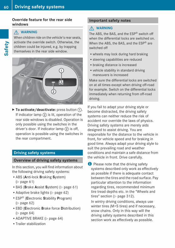
Override feature for the rear sidewindows
G WARNINGWhen children ride on the vehicle's rear seats,activate the override switch. Otherwise, thechildren could be injured, e.g. by trappingthemselves in the rear side window.
X To activate/deactivate: press button:.If indicator lamp; is lit, operation of therear side windows is disabled. Operation isonly possible using the switches in thedriver's door. If indicator lamp; is off,operation is possible using the switches inthe rear compartment.
Driving safety systems
Overview of driving safety systemsIn this section, you will find information aboutthe following driving safety systems:RABS (Anti-lock Braking System)(Y page 61)RBAS (Brake Assist System) (Y page 61)RAdaptive brake lights (Y page 62)RESP® (Electronic Stability Program)(Y page 62)REBD (Electronic Brake force Distribution)(Y page 64)RADAPTIVE BRAKE (Y page 64)RTrailer stabilization
Important safety notes
G WARNINGThe ABS, the BAS, and the ESP® switch offwhen the differential locks are switched on.When the ABS, the BAS, and the ESP® areswitched offRwheels may lock during hard brakingRsteering capabilities are reducedRbraking distance is increasedRvehicle stability in standard drivingmaneuvers is increased
Make sure the differential locks are switchedon at all times except when driving off-roadfor example. Switch on the differential locksimmediately when returning from off-roaddriving.
If you fail to adapt your driving style orbecome distracted, the driving safetysystems can neither reduce the risk ofaccident nor override the laws of physics.Driving safety systems are merely aidsdesigned to assist driving. You areresponsible for the distance to the vehicle infront, for vehicle speed and for braking ingood time. Always adapt your driving style tosuit the prevailing road and weatherconditions and maintain a safe distance fromthe vehicle in front. Drive carefully.
i Please note that the driving safetysystems described only work as effectivelyas possible if there is adequate contactbetween the tires and the road surface. Payparticular attention to the informationregarding tires, recommended minimumtire tread depths etc. in the "Wheels andtires" section (Y page 312).In wintry driving conditions, always usewinter tires (M+S tires) and if necessary,snow chains. Only in this way will thedriving safety systems described in thissection work as effectively as possible.
60 Driving safety systemsSafety
ABS (Anti-lock Braking System)
Important safety notesi Observe the "Important safety notes"section (Y page 60).
G WARNINGIf the ABSmalfunctions, other driving systemssuch as the BAS or the ESP® are also switchedoff. Observe indicator and warning lamps thatmay come on as well as messages in themultifunction display that may appear.If the ABS malfunctions, the wheels may lockduring hard braking, reducing the steeringcapability and extending the braking distance.
G WARNINGIf ABS is faulty, the wheels could lock whenbraking. The steerability and brakingcharacteristics may be severely impaired.Additionally, further driving safety systemsare deactivated. There is an increased dangerof skidding and accidents.Drive on carefully. Have ABS checkedimmediately at a qualified specialistworkshop.
ABS regulates brake pressure in such a waythat the wheels do not lock when you brake.This allows you to continue steering thevehicle when braking.Provided that the differential locks are notactive, ABS works from a speed of about5 mph (8 km/h) upwards, regardless of road-surface conditions. ABS works on slipperysurfaces, even if you only brake gently.The yellow ! ABS warning lamp in theinstrument cluster lights up when the ignitionis switched on. It goes out when the engine isrunning.
BrakingIf ABS intervenes when braking, you will feela pulsing in the brake pedal.
X If ABS intervenes: continue to depress thebrake pedal vigorously until the brakingsituation is over.
X To make a full brake application:depress the brake pedal with full force.
The pulsating brake pedal can be anindication of hazardous road conditions, andfunctions as a reminder to take extra carewhile driving.
Off-road ABSIf the LOW RANGE shift range is selected bythe transfer case, (Y page 194), an ABSsystem specifically suited to off-road terrainis automatically activated.At speeds below 37mph (60 km/h), the frontwheels lock cyclically during braking. Thedigging-in effect achieved in the processreduces the stopping distance on off-roadterrain. This limits steering capability.
BAS (Brake Assist System)i Observe the "Important safety notes"section (Y page 60).
G WARNINGIf BAS is malfunctioning, the braking distancein an emergency braking situation isincreased. There is a risk of an accident.In an emergency braking situation, depressthe brake pedal with full force. ABS preventsthe wheels from locking.
BAS operates in emergency brakingsituations. If you depress the brake pedalquickly, BAS automatically boosts the brakingforce, thus shortening the stopping distance.X Keep the brake pedal firmly depressed untilthe emergency braking situation is over.ABS prevents the wheels from locking.
The brakes will function as usual once yourelease the brake pedal. BAS is deactivated.
Driving safety systems 61
Safety
Z
Adaptive brake lightsIf you brake sharply from a speed of morethan 30 mph (50 km/h) or if braking isassisted by BAS, the brake lamps flashrapidly. In this way, traffic traveling behindyou is warned in an even more noticeablemanner.If you brake sharply from a speed of morethan 45 mph (70 km/h) to a standstill, thehazard warning lamps are activatedautomatically. If the brakes are applied again,the brake lamps light up continuously. If youdrive faster than 6mph (10 km/h), the hazardwarning lamps are deactivated automatically.You can also switch off the hazard warninglamps using the hazard warning button(Y page 104).
ESP® (Electronic Stability Program)
Important safety notesi Observe the "Important safety notes"section (Y page 60).
G WARNINGIf ESP® is malfunctioning, ESP® is unable tostabilize the vehicle. Additionally, furtherdriving safety systems are deactivated. Thisincreases the risk of skidding and an accident.Drive on carefully. Have ESP® checked at aqualified specialist workshop.
! Only operate the vehicle for a maximumof ten seconds on a brake testdynamometer. Switch off the ignition.Application of the brakes by ESP® mayotherwise destroy the brake system.
! A function or performance test shouldonly be carried out on a two-axledynamometer. Before you operate thevehicle on such a dynamometer, pleaseconsult a qualified workshop. You couldotherwise damage the drive train or thebrake system.
ESP® monitors driving stability and traction.Traction is the power transmission betweenthe tires and the road surface.ESP® is deactivated if the å warning lampin the instrument cluster lights upcontinuously when the engine is running.If the ÷ warning lamp and the åwarning lamp are lit continuously, ESP® is notavailable due to a malfunction.Observe the information on warning lamps(Y page 247) and any display messages thatappear in the instrument cluster(Y page 221).If ESP® detects that the vehicle is deviatingfrom the direction desired by the driver, oneor more wheels are braked to stabilize thevehicle. If necessary, the engine output is alsomodified to keep the vehicle on the desiredcourse within physical limits. ESP® assiststhe driver when pulling away on wet orslippery roads. ESP® can also stabilize thevehicle during braking.If ESP® intervenes, the ÷ warning lampflashes in the instrument cluster.If ESP® intervenes:X Do not deactivate ESP® under anycircumstances.
X Only depress the accelerator pedal as faras necessary when pulling away.
X Adapt your driving style to suit theprevailing road and weather conditions.
i Only use wheels with the recommendedtire sizes. Only then will ESP® functionproperly.
i If differential locks are switched on, ABS,BAS and ESP® switch themselves offautomatically.
4ETS (Electronic Traction System)Traction control remains active if youdeactivate ESP®.
62 Driving safety systemsSafety
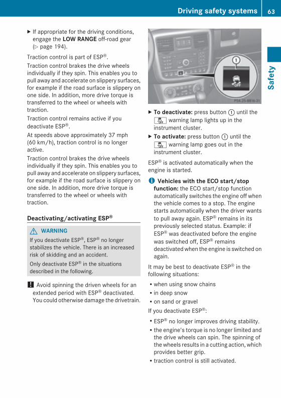
X If appropriate for the driving conditions,engage the LOW RANGE off-road gear(Y page 194).
Traction control is part of ESP®.Traction control brakes the drive wheelsindividually if they spin. This enables you topull away and accelerate on slippery surfaces,for example if the road surface is slippery onone side. In addition, more drive torque istransferred to the wheel or wheels withtraction.Traction control remains active if youdeactivate ESP®.At speeds above approximately 37 mph(60 km/h), traction control is no longeractive.Traction control brakes the drive wheelsindividually if they spin. This enables you topull away and accelerate on slippery surfaces,for example if the road surface is slippery onone side. In addition, more drive torque istransferred to the wheel or wheels withtraction.
Deactivating/activating ESP®
G WARNINGIf you deactivate ESP®, ESP® no longerstabilizes the vehicle. There is an increasedrisk of skidding and an accident.Only deactivate ESP® in the situationsdescribed in the following.
! Avoid spinning the driven wheels for anextended period with ESP® deactivated.You could otherwise damage the drivetrain.
X To deactivate: press button: until theå warning lamp lights up in theinstrument cluster.
X To activate: press button: until theå warning lamp goes out in theinstrument cluster.
ESP® is activated automatically when theengine is started.
i Vehicles with the ECO start/stopfunction: the ECO start/stop functionautomatically switches the engine off whenthe vehicle comes to a stop. The enginestarts automatically when the driver wantsto pull away again. ESP® remains in itspreviously selected status. Example: ifESP® was deactivated before the enginewas switched off, ESP® remainsdeactivatedwhen the engine is switched onagain.
It may be best to deactivate ESP® in thefollowing situations:Rwhen using snow chainsRin deep snowRon sand or gravelIf you deactivate ESP®:RESP® no longer improves driving stability.Rthe engine's torque is no longer limited andthe drive wheels can spin. The spinning ofthewheels results in a cutting action, whichprovides better grip.Rtraction control is still activated.
Driving safety systems 63
Safety
Z
RESP® still provides support when youbrake.Rand are driving above 37 mph (60 km/h)(on AMG vehicles above 62 mph(100 km/h)), ESP® still intervenes whenone wheel reaches its grip limit eventhough it is switched off.
i If ESP® is deactivated and one or morewheels start to spin, the÷warning lampin the instrument cluster flashes. In suchsituations, ESP® will not stabilize thevehicle.
i If you have switched off ESP®, it switcheson again automatically at speeds above37mph (60 km/h) (on AMG vehicles above62 mph (100 km/h)) or if you haveexceeded a certain lateral acceleration.
Trailer stabilization
G WARNINGIf road and weather conditions are poor,trailer stabilization will not be able to preventthe vehicle/trailer combination fromswerving. Trailers with a high center of gravitycan tip over before ESP® can detect this.There is a risk of an accident.Always adapt your driving style to theprevailing road and weather conditions.
Trailer stabilization does not work if ESP® isdeactivated because of a malfunction.If your vehicle with trailer (vehicle/trailercombination) begins to lurch, you can onlystabilize the vehicle/trailer combination bydepressing the brake firmly.In this situation, ESP® assists you and candetect if the vehicle/trailer combinationbegins to lurch. ESP® slows the vehicle downby braking and limiting the engine output untilthe vehicle/trailer combination hasstabilized.Trailer stabilization is active above speeds ofabout 37 mph (60 km/h).
EBD (electronic brake forcedistribution)i Observe the "Important safety notes"section (Y page 60).
G WARNINGIf EBD hasmalfunctioned, the rear wheels canstill lock, e.g. under full braking. Thisincreases the risk of skidding and an accident.You should therefore adapt your driving styleto the different handling characteristics. Havethe brake system checked at a qualifiedspecialist workshop.
Observe information regarding indicator andwarning lamps (Y page 245) as well asdisplay messages (Y page 223).EBD monitors and controls the brakepressure on the rear wheels to improvedriving stability while braking.
ADAPTIVE BRAKEADAPTIVE BRAKE provides increased brakingsafety. In addition to the braking function,ADAPTIVE BRAKE also has the HOLD function(Y page 188) and hill start assist(Y page 141).
Theft deterrent locking system
ImmobilizerX To activate: remove the SmartKey fromthe ignition lock.
X To deactivate: switch on the ignition.The immobilizer prevents your vehicle frombeing started without the correct SmartKey.When leaving the vehicle, always take theSmartKey with you and lock the vehicle. Theengine can be started by anyone with a validSmartKey that is left inside the vehicle.
i The immobilizer is always deactivatedwhen you start the engine.
64 Theft deterrent locking systemSafety
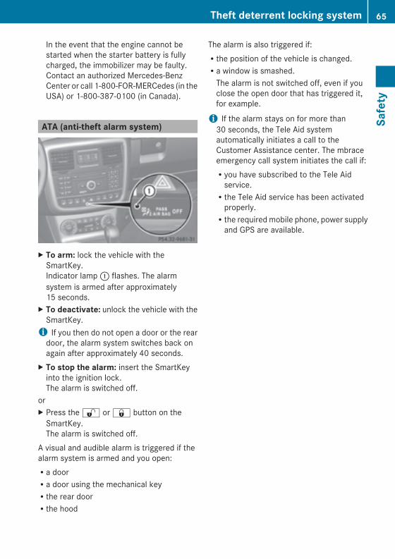
In the event that the engine cannot bestarted when the starter battery is fullycharged, the immobilizer may be faulty.Contact an authorized Mercedes-BenzCenter or call 1-800-FOR-MERCedes (in theUSA) or 1-800-387-0100 (in Canada).
ATA (anti-theft alarm system)
X To arm: lock the vehicle with theSmartKey.Indicator lamp: flashes. The alarmsystem is armed after approximately15 seconds.
X To deactivate: unlock the vehicle with theSmartKey.i If you then do not open a door or the reardoor, the alarm system switches back onagain after approximately 40 seconds.
X To stop the alarm: insert the SmartKeyinto the ignition lock.The alarm is switched off.
orX Press the% or& button on theSmartKey.The alarm is switched off.
A visual and audible alarm is triggered if thealarm system is armed and you open:Ra doorRa door using the mechanical keyRthe rear doorRthe hood
The alarm is also triggered if:Rthe position of the vehicle is changed.Ra window is smashed.The alarm is not switched off, even if youclose the open door that has triggered it,for example.
i If the alarm stays on for more than30 seconds, the Tele Aid systemautomatically initiates a call to theCustomer Assistance center. The mbraceemergency call system initiates the call if:Ryou have subscribed to the Tele Aidservice.Rthe Tele Aid service has been activatedproperly.Rthe requiredmobile phone, power supplyand GPS are available.
Theft deterrent locking system 65
Safety
Z

66
Useful information .............................. 68SmartKey ............................................. 68Doors .................................................... 73Rear door ............................................. 76Side windows ...................................... 77Sliding sunroof .................................... 79
67
Openingandclosing
Useful information
i This Operator's Manual describes allmodels and all standard and optionalequipment of your vehicle available at thetime of publication of the Operator'sManual. Country-specific differences arepossible. Please note that your vehicle maynot be equipped with all featuresdescribed. This also applies to safety-related systems and functions.
i Read the information on qualifiedspecialist workshops: (Y page 24).
SmartKey
Important safety notes
G WARNINGWhen leaving the vehicle, always remove theSmartKey from the ignition lock. Always takethe SmartKey with you and lock the vehicle.Do not leave children unsupervised in thevehicle, even if they are secured in a childrestraint system, and do not give them accessto an unlocked vehicle. A child's unsupervisedaccess to a vehicle could result in an accidentand/or serious personal injury. They could:Rinjure themselves on vehicle partsRbe seriously or fatally injured by extremeheat or coldRinjure themselves or have an accident withvehicle equipment that may still be inoperation even after the SmartKey hasbeen removed from the ignition, such as theseat adjustment, steering wheeladjustment or memory function.
If children open a door, they could causesevere or even fatal injury to other persons; ifthey get out of the vehicle, they could injurethemselves when doing so or be seriously oreven fatally injured by any passing traffic.Do not expose the child restraint system todirect sunlight. The child restraint system'smetal parts, for example, could become very
hot, and a child could be burned on theseparts.
G WARNINGDo not carry heavy or hard objects in thepassenger compartment or cargocompartment unless they are firmly securedin place.Unsecured or improperly positioned cargoincreases a child's risk of injury in the eventofRstrong braking maneuversRsudden changes of directionRan accident
G WARNINGIf you attach heavy or large objects to theSmartKey, the SmartKey could beunintentionally turned in the ignition lock. Thiscould cause the engine to be switched off.There is a risk of an accident.Do not attach any heavy or large objects tothe SmartKey. Remove any bulky key ringsbefore inserting the SmartKey into theignition lock.
SmartKey functions
G WARNINGIf children are left unsupervised in the vehicle,they could:Ropen the doors, thus endangering otherpeople or road users.Rget out and disrupt traffic.Roperate the vehicle's equipment.Additionally, children could set the vehicle inmotion if, for example, they:Rrelease the parking brake.Rshift the automatic transmission out ofparking position P.Rshift the manual transmission into neutral.Rstarting the engine.There is a risk of an accident and injury.
68 SmartKeyOp
eningandclosing
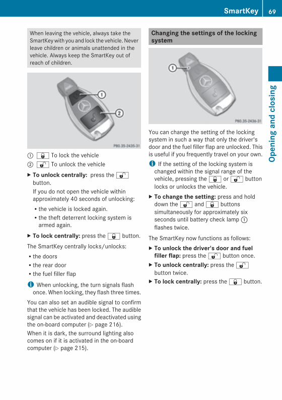
When leaving the vehicle, always take theSmartKeywith you and lock the vehicle. Neverleave children or animals unattended in thevehicle. Always keep the SmartKey out ofreach of children.
: & To lock the vehicle; % To unlock the vehicleX To unlock centrally: press the%button.If you do not open the vehicle withinapproximately 40 seconds of unlocking:Rthe vehicle is locked again.Rthe theft deterrent locking system isarmed again.
X To lock centrally: press the& button.
The SmartKey centrally locks/unlocks:Rthe doorsRthe rear doorRthe fuel filler flap
i When unlocking, the turn signals flashonce. When locking, they flash three times.
You can also set an audible signal to confirmthat the vehicle has been locked. The audiblesignal can be activated and deactivated usingthe on-board computer (Y page 216).When it is dark, the surround lighting alsocomes on if it is activated in the on-boardcomputer (Y page 215).
Changing the settings of the lockingsystem
You can change the setting of the lockingsystem in such a way that only the driver'sdoor and the fuel filler flap are unlocked. Thisis useful if you frequently travel on your own.i If the setting of the locking system ischanged within the signal range of thevehicle, pressing the& or% buttonlocks or unlocks the vehicle.
X To change the setting: press and holddown the% and& buttonssimultaneously for approximately sixseconds until battery check lamp:flashes twice.
The SmartKey now functions as follows:X To unlock the driver's door and fuelfiller flap: press the% button once.
X To unlock centrally: press the%button twice.
X To lock centrally: press the& button.
SmartKey 69
Openingandclosing
Z
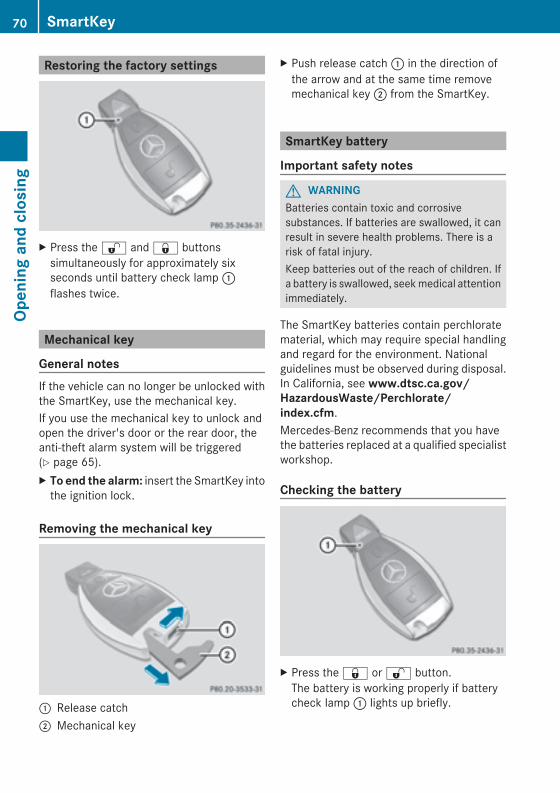
Restoring the factory settings
X Press the% and& buttonssimultaneously for approximately sixseconds until battery check lamp:flashes twice.
Mechanical key
General notesIf the vehicle can no longer be unlocked withthe SmartKey, use the mechanical key.If you use the mechanical key to unlock andopen the driver's door or the rear door, theanti-theft alarm system will be triggered(Y page 65).X To end the alarm: insert the SmartKey intothe ignition lock.
Removing the mechanical key
: Release catch; Mechanical key
X Push release catch: in the direction ofthe arrow and at the same time removemechanical key; from the SmartKey.
SmartKey battery
Important safety notes
G WARNINGBatteries contain toxic and corrosivesubstances. If batteries are swallowed, it canresult in severe health problems. There is arisk of fatal injury.Keep batteries out of the reach of children. Ifa battery is swallowed, seekmedical attentionimmediately.
The SmartKey batteries contain perchloratematerial, which may require special handlingand regard for the environment. Nationalguidelines must be observed during disposal.In California, see www.dtsc.ca.gov/HazardousWaste/Perchlorate/index.cfm.Mercedes-Benz recommends that you havethe batteries replaced at a qualified specialistworkshop.
Checking the battery
X Press the& or% button.The battery is working properly if batterycheck lamp: lights up briefly.
70 SmartKeyOp
eningandclosing
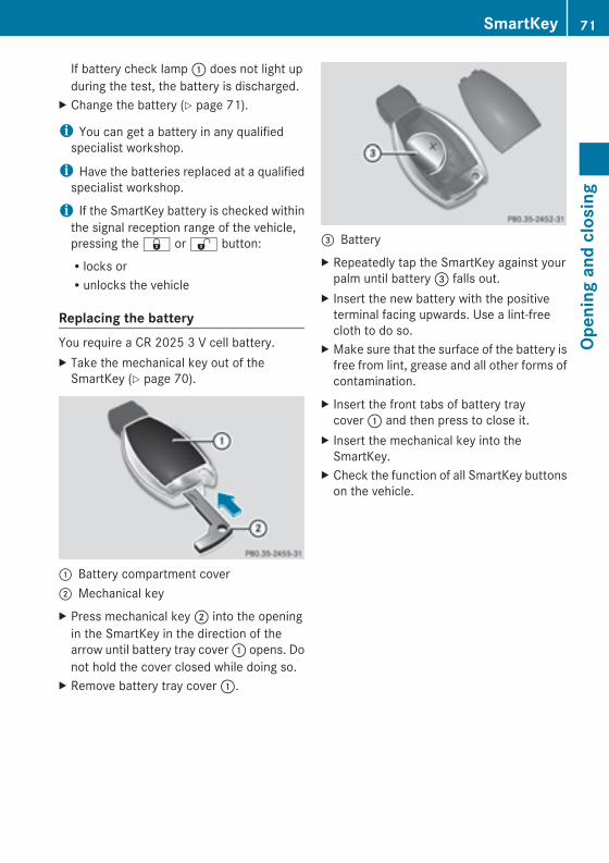
If battery check lamp: does not light upduring the test, the battery is discharged.
X Change the battery (Y page 71).
i You can get a battery in any qualifiedspecialist workshop.
i Have the batteries replaced at a qualifiedspecialist workshop.
i If the SmartKey battery is checked withinthe signal reception range of the vehicle,pressing the& or% button:Rlocks orRunlocks the vehicle
Replacing the batteryYou require a CR 2025 3 V cell battery.X Take the mechanical key out of theSmartKey (Y page 70).
: Battery compartment cover; Mechanical keyX Press mechanical key; into the openingin the SmartKey in the direction of thearrow until battery tray cover: opens. Donot hold the cover closed while doing so.
X Remove battery tray cover:.
= BatteryX Repeatedly tap the SmartKey against yourpalm until battery= falls out.
X Insert the new battery with the positiveterminal facing upwards. Use a lint-freecloth to do so.
X Make sure that the surface of the battery isfree from lint, grease and all other forms ofcontamination.
X Insert the front tabs of battery traycover: and then press to close it.
X Insert the mechanical key into theSmartKey.
X Check the function of all SmartKey buttonson the vehicle.
SmartKey 71
Openingandclosing
Z
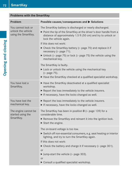
Problems with the SmartKey
Problem Possible causes/consequences andMM Solutions
You cannot lock orunlock the vehicleusing the SmartKey.
The SmartKey battery is discharged or nearly discharged.X Point the tip of the SmartKey at the driver's door handle from adistance of approximately 1.5 ft (50 cm) and try to unlock orlock the vehicle again.
If this does not work:X Check the SmartKey battery (Y page 70) and replace it ifnecessary (Y page 71).
X Unlock (Y page 75) or lock (Y page 75) the vehicle using themechanical key.
The SmartKey is faulty.X Lock or unlock the vehicle using the mechanical key(Y page 75).
X Have the SmartKey checked at a qualified specialist workshop.
You have lost aSmartKey.
X Have the SmartKey deactivated at a qualified specialistworkshop.
X Report the loss immediately to the vehicle insurers.X If necessary, have the locks changed as well.
You have lost themechanical key.
X Report the loss immediately to the vehicle insurers.X If necessary, have the locks changed as well.
The engine cannot bestarted using theSmartKey.
The SmartKey has been in position 0 (Y page 139) for aconsiderable time.X Remove the SmartKey and reinsert it into the ignition lock.X Start the engine.
The on-board voltage is too low.X Switch off non-essential consumers, e.g. seat heating or interiorlighting, and try to turn the SmartKey again.
If this does not work:X Check the battery and charge it if necessary (Y page 301).orX Jump-start the vehicle (Y page 303).orX Consult a qualified specialist workshop.
72 SmartKeyOp
eningandclosing
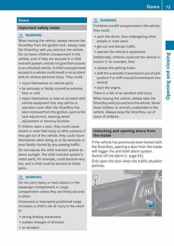
Doors
Important safety notes
G WARNINGWhen leaving the vehicle, always remove theSmartKey from the ignition lock. Always takethe SmartKey with you and lock the vehicle.Do not leave children unsupervised in thevehicle, even if they are secured in a childrestraint system, and do not give them accessto an unlocked vehicle. A child's unsupervisedaccess to a vehicle could result in an accidentand/or serious personal injury. They could:Rinjure themselves on vehicle partsRbe seriously or fatally injured by extremeheat or coldRinjure themselves or have an accident withvehicle equipment that may still be inoperation even after the SmartKey hasbeen removed from the ignition, such as theseat adjustment, steering wheeladjustment or memory function.
If children open a door, they could causesevere or even fatal injury to other persons; ifthey get out of the vehicle, they could injurethemselves when doing so or be seriously oreven fatally injured by any passing traffic.Do not expose the child restraint system todirect sunlight. The child restraint system'smetal parts, for example, could become veryhot, and a child could be burned on theseparts.
G WARNINGDo not carry heavy or hard objects in thepassenger compartment or cargocompartment unless they are firmly securedin place.Unsecured or improperly positioned cargoincreases a child's risk of injury in the eventofRstrong braking maneuversRsudden changes of directionRan accident
G WARNINGIf children are left unsupervised in the vehicle,they could:Ropen the doors, thus endangering otherpeople or road users.Rget out and disrupt traffic.Roperate the vehicle's equipment.Additionally, children could set the vehicle inmotion if, for example, they:Rrelease the parking brake.Rshift the automatic transmission out of parkposition P or shift manual transmission intoneutral.Rstart the engine.There is a risk of an accident and injury.When leaving the vehicle, always take theSmartKeywith you and lock the vehicle. Neverleave children or animals unattended in thevehicle. Always keep the SmartKey out ofreach of children.
Unlocking and opening doors fromthe insideIf the vehicle has previously been locked withthe SmartKey, opening a door from the insidewill trigger the anti-theft alarm system.Switch off the alarm (Y page 65).Only open the door when the traffic situationpermits.
Doors 73
Openingandclosing
Z
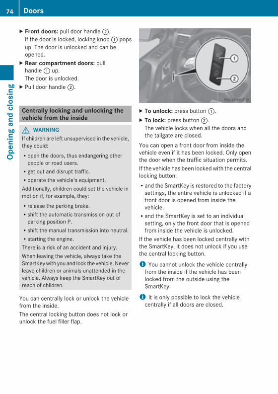
X Front doors: pull door handle;.If the door is locked, locking knob: popsup. The door is unlocked and can beopened.
X Rear compartment doors: pullhandle: up.The door is unlocked.
X Pull door handle;.
Centrally locking and unlocking thevehicle from the inside
G WARNINGIf children are left unsupervised in the vehicle,they could:Ropen the doors, thus endangering otherpeople or road users.Rget out and disrupt traffic.Roperate the vehicle's equipment.Additionally, children could set the vehicle inmotion if, for example, they:Rrelease the parking brake.Rshift the automatic transmission out ofparking position P.Rshift the manual transmission into neutral.Rstarting the engine.There is a risk of an accident and injury.When leaving the vehicle, always take theSmartKeywith you and lock the vehicle. Neverleave children or animals unattended in thevehicle. Always keep the SmartKey out ofreach of children.
You can centrally lock or unlock the vehiclefrom the inside.The central locking button does not lock orunlock the fuel filler flap.
X To unlock: press button:.X To lock: press button;.The vehicle locks when all the doors andthe tailgate are closed.
You can open a front door from inside thevehicle even if it has been locked. Only openthe door when the traffic situation permits.If the vehicle has been locked with the centrallocking button:Rand the SmartKey is restored to the factorysettings, the entire vehicle is unlocked if afront door is opened from inside thevehicle.Rand the SmartKey is set to an individualsetting, only the front door that is openedfrom inside the vehicle is unlocked.
If the vehicle has been locked centrally withthe SmartKey, it does not unlock if you usethe central locking button.
i You cannot unlock the vehicle centrallyfrom the inside if the vehicle has beenlocked from the outside using theSmartKey.
i It is only possible to lock the vehiclecentrally if all doors are closed.
74 DoorsOp
eningandclosing
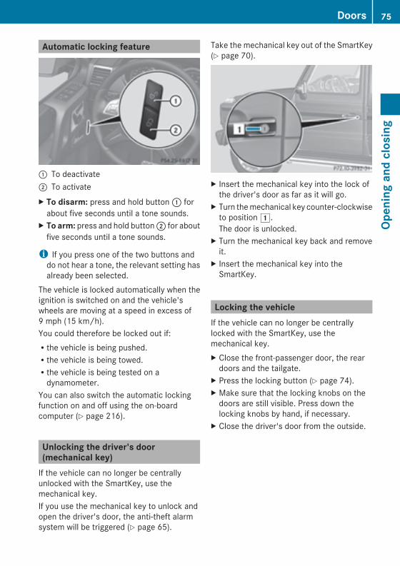
Automatic locking feature
: To deactivate; To activateX To disarm: press and hold button: forabout five seconds until a tone sounds.
X To arm: press and hold button; for aboutfive seconds until a tone sounds.
i If you press one of the two buttons anddo not hear a tone, the relevant setting hasalready been selected.
The vehicle is locked automatically when theignition is switched on and the vehicle'swheels are moving at a speed in excess of9 mph (15 km/h).You could therefore be locked out if:Rthe vehicle is being pushed.Rthe vehicle is being towed.Rthe vehicle is being tested on adynamometer.
You can also switch the automatic lockingfunction on and off using the on-boardcomputer (Y page 216).
Unlocking the driver's door(mechanical key)If the vehicle can no longer be centrallyunlocked with the SmartKey, use themechanical key.If you use the mechanical key to unlock andopen the driver's door, the anti-theft alarmsystem will be triggered (Y page 65).
Take the mechanical key out of the SmartKey(Y page 70).
X Insert the mechanical key into the lock ofthe driver's door as far as it will go.
X Turn themechanical key counter-clockwiseto position1.The door is unlocked.
X Turn the mechanical key back and removeit.
X Insert the mechanical key into theSmartKey.
Locking the vehicleIf the vehicle can no longer be centrallylocked with the SmartKey, use themechanical key.X Close the front-passenger door, the reardoors and the tailgate.
X Press the locking button (Y page 74).X Make sure that the locking knobs on thedoors are still visible. Press down thelocking knobs by hand, if necessary.
X Close the driver's door from the outside.
Doors 75
Openingandclosing
Z
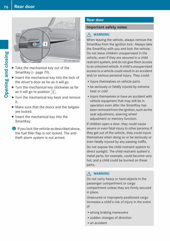
X Take the mechanical key out of theSmartKey (Y page 70).
X Insert the mechanical key into the lock ofthe driver's door as far as it will go.
X Turn the mechanical key clockwise as faras it will go to position1.
X Turn the mechanical key back and removeit.
X Make sure that the doors and the tailgateare locked.
X Insert the mechanical key into theSmartKey.
i If you lock the vehicle as described above,the fuel filler flap is not locked. The anti-theft alarm system is not armed.
Rear door
Important safety notes
G WARNINGWhen leaving the vehicle, always remove theSmartKey from the ignition lock. Always takethe SmartKey with you and lock the vehicle.Do not leave children unsupervised in thevehicle, even if they are secured in a childrestraint system, and do not give them accessto an unlocked vehicle. A child's unsupervisedaccess to a vehicle could result in an accidentand/or serious personal injury. They could:Rinjure themselves on vehicle partsRbe seriously or fatally injured by extremeheat or coldRinjure themselves or have an accident withvehicle equipment that may still be inoperation even after the SmartKey hasbeen removed from the ignition, such as theseat adjustment, steering wheeladjustment or memory function.
If children open a door, they could causesevere or even fatal injury to other persons; ifthey get out of the vehicle, they could injurethemselves when doing so or be seriously oreven fatally injured by any passing traffic.Do not expose the child restraint system todirect sunlight. The child restraint system'smetal parts, for example, could become veryhot, and a child could be burned on theseparts.
G WARNINGDo not carry heavy or hard objects in thepassenger compartment or cargocompartment unless they are firmly securedin place.Unsecured or improperly positioned cargoincreases a child's risk of injury in the eventofRstrong braking maneuversRsudden changes of directionRan accident
76 Rear doorOp
eningandclosing
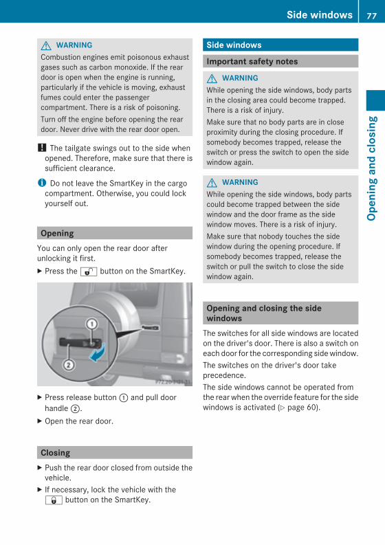
G WARNINGCombustion engines emit poisonous exhaustgases such as carbon monoxide. If the reardoor is open when the engine is running,particularly if the vehicle is moving, exhaustfumes could enter the passengercompartment. There is a risk of poisoning.Turn off the engine before opening the reardoor. Never drive with the rear door open.
! The tailgate swings out to the side whenopened. Therefore, make sure that there issufficient clearance.
i Do not leave the SmartKey in the cargocompartment. Otherwise, you could lockyourself out.
OpeningYou can only open the rear door afterunlocking it first.X Press the% button on the SmartKey.
X Press release button: and pull doorhandle;.
X Open the rear door.
ClosingX Push the rear door closed from outside thevehicle.
X If necessary, lock the vehicle with the& button on the SmartKey.
Side windows
Important safety notes
G WARNINGWhile opening the side windows, body partsin the closing area could become trapped.There is a risk of injury.Make sure that no body parts are in closeproximity during the closing procedure. Ifsomebody becomes trapped, release theswitch or press the switch to open the sidewindow again.
G WARNINGWhile opening the side windows, body partscould become trapped between the sidewindow and the door frame as the sidewindow moves. There is a risk of injury.Make sure that nobody touches the sidewindow during the opening procedure. Ifsomebody becomes trapped, release theswitch or pull the switch to close the sidewindow again.
Opening and closing the sidewindowsThe switches for all side windows are locatedon the driver's door. There is also a switch oneach door for the corresponding sidewindow.The switches on the driver's door takeprecedence.The side windows cannot be operated fromthe rear when the override feature for the sidewindows is activated (Y page 60).
Side windows 77
Openingandclosing
Z
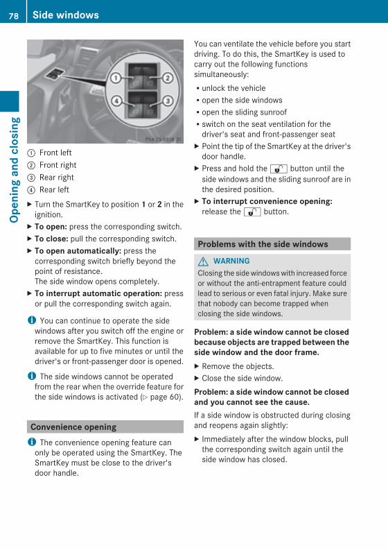
: Front left; Front right= Rear right? Rear leftX Turn the SmartKey to position 1 or 2 in theignition.
X To open: press the corresponding switch.X To close: pull the corresponding switch.X To open automatically: press thecorresponding switch briefly beyond thepoint of resistance.The side window opens completely.
X To interrupt automatic operation: pressor pull the corresponding switch again.
i You can continue to operate the sidewindows after you switch off the engine orremove the SmartKey. This function isavailable for up to five minutes or until thedriver's or front-passenger door is opened.
i The side windows cannot be operatedfrom the rear when the override feature forthe side windows is activated (Y page 60).
Convenience openingi The convenience opening feature canonly be operated using the SmartKey. TheSmartKey must be close to the driver'sdoor handle.
You can ventilate the vehicle before you startdriving. To do this, the SmartKey is used tocarry out the following functionssimultaneously:Runlock the vehicleRopen the side windowsRopen the sliding sunroofRswitch on the seat ventilation for thedriver's seat and front-passenger seat
X Point the tip of the SmartKey at the driver'sdoor handle.
X Press and hold the% button until theside windows and the sliding sunroof are inthe desired position.
X To interrupt convenience opening:release the% button.
Problems with the side windows
G WARNINGClosing the sidewindowswith increased forceor without the anti-entrapment feature couldlead to serious or even fatal injury. Make surethat nobody can become trapped whenclosing the side windows.
Problem: a side window cannot be closedbecause objects are trapped between theside window and the door frame.X Remove the objects.X Close the side window.Problem: a side window cannot be closedand you cannot see the cause.If a side window is obstructed during closingand reopens again slightly:X Immediately after the window blocks, pullthe corresponding switch again until theside window has closed.
78 Side windowsOp
eningandclosing
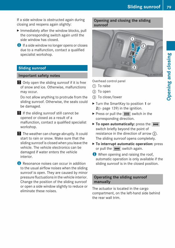
If a side window is obstructed again duringclosing and reopens again slightly:X Immediately after the window blocks, pullthe corresponding switch again until theside window has closed.i If a side window no longer opens or closesdue to a malfunction, contact a qualifiedspecialist workshop.
Sliding sunroof
Important safety notes! Only open the sliding sunroof if it is freeof snow and ice. Otherwise, malfunctionsmay occur.Do not allow anything to protrude from thesliding sunroof. Otherwise, the seals couldbe damaged.
! If the sliding sunroof still cannot beopened or closed as a result of amalfunction, contact a qualified specialistworkshop.
! The weather can change abruptly. It couldstart to rain or snow. Make sure that thesliding sunroof is closedwhen you leave thevehicle. The vehicle electronics can bedamaged if water enters the vehicleinterior.
i Resonance noises can occur in additionto the usual airflow noises when the slidingsunroof is open. They are caused by minorpressure fluctuations in the vehicle interior.Change the position of the sliding sunroofor open a side window slightly to reduce oreliminate these noises.
Opening and closing the slidingsunroof
Overhead control panel: To raise; To open= To close/lowerX Turn the SmartKey to position 1 or2(Y page 139) in the ignition.
X Press or pull the¡ switch in thecorresponding direction.
X To open automatically: press the¡switch briefly beyond the point ofresistance in the direction of arrow;.The sliding sunroof opens completely.
X To interrupt automatic operation: pressor pull the¡ switch again.i When opening and raising the roof,automatic operation is only available if thesliding sunroof is in the closed position.
Operating the sliding sunroofmanuallyThe actuator is located in the cargocompartment, on the left-hand side behindthe rear wall trim.
Sliding sunroof 79
Openingandclosing
Z
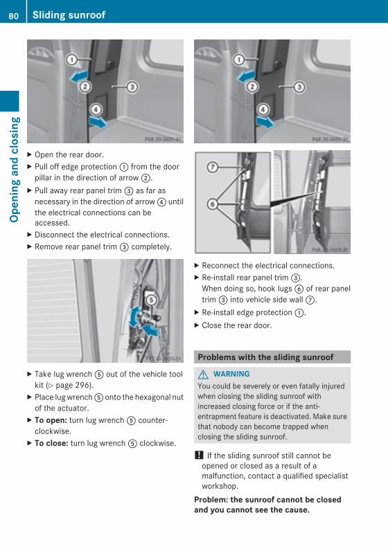
X Open the rear door.X Pull off edge protection: from the doorpillar in the direction of arrow;.
X Pull away rear panel trim= as far asnecessary in the direction of arrow? untilthe electrical connections can beaccessed.
X Disconnect the electrical connections.X Remove rear panel trim= completely.
X Take lug wrenchA out of the vehicle toolkit (Y page 296).
X Place lugwrenchA onto the hexagonal nutof the actuator.
X To open: turn lug wrenchA counter-clockwise.
X To close: turn lug wrenchA clockwise.
X Reconnect the electrical connections.X Re-install rear panel trim=.When doing so, hook lugsB of rear paneltrim= into vehicle side wallC.
X Re-install edge protection:.X Close the rear door.
Problems with the sliding sunroof
G WARNINGYou could be severely or even fatally injuredwhen closing the sliding sunroof withincreased closing force or if the anti-entrapment feature is deactivated. Make surethat nobody can become trapped whenclosing the sliding sunroof.
! If the sliding sunroof still cannot beopened or closed as a result of amalfunction, contact a qualified specialistworkshop.
Problem: the sunroof cannot be closedand you cannot see the cause.
80 Sliding sunroofOp
eningandclosing
If the sliding sunroof is obstructed duringclosing and reopens again slightly:X Immediately after the sliding sunroofblocks, pull the¡ switch in theoverhead control panel down to the pointof resistance and hold it until the slidingsunroof is closed.
If the sliding sunroof is obstructed againduring closing and reopens again slightly:X Immediately after the sliding sunroofblocks, pull the¡ switch in theoverhead control panel down to the pointof resistance and hold it until the slidingsunroof is closed.
Sliding sunroof 81
Openingandclosing
Z

82
Useful information .............................. 84Correct driver's seat position ............ 84Seats .................................................... 85Steering wheel .................................... 90Mirrors ................................................. 93Memory functions ............................... 95
83
Seats,steerin
gwheelandmirrors
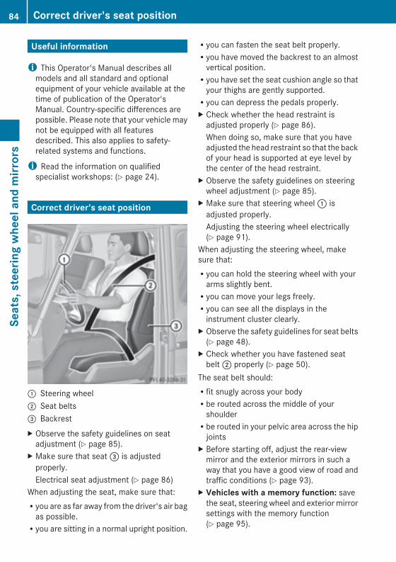
Useful information
i This Operator's Manual describes allmodels and all standard and optionalequipment of your vehicle available at thetime of publication of the Operator'sManual. Country-specific differences arepossible. Please note that your vehicle maynot be equipped with all featuresdescribed. This also applies to safety-related systems and functions.
i Read the information on qualifiedspecialist workshops: (Y page 24).
Correct driver's seat position
: Steering wheel; Seat belts= BackrestX Observe the safety guidelines on seatadjustment (Y page 85).
X Make sure that seat= is adjustedproperly.Electrical seat adjustment (Y page 86)
When adjusting the seat, make sure that:Ryou are as far away from the driver's air bagas possible.Ryou are sitting in a normal upright position.
Ryou can fasten the seat belt properly.Ryou have moved the backrest to an almostvertical position.Ryou have set the seat cushion angle so thatyour thighs are gently supported.Ryou can depress the pedals properly.X Check whether the head restraint isadjusted properly (Y page 86).When doing so, make sure that you haveadjusted the head restraint so that the backof your head is supported at eye level bythe center of the head restraint.
X Observe the safety guidelines on steeringwheel adjustment (Y page 85).
X Make sure that steering wheel: isadjusted properly.Adjusting the steering wheel electrically(Y page 91).
When adjusting the steering wheel, makesure that:Ryou can hold the steering wheel with yourarms slightly bent.Ryou can move your legs freely.Ryou can see all the displays in theinstrument cluster clearly.
X Observe the safety guidelines for seat belts(Y page 48).
X Check whether you have fastened seatbelt; properly (Y page 50).
The seat belt should:Rfit snugly across your bodyRbe routed across the middle of yourshoulderRbe routed in your pelvic area across the hipjoints
X Before starting off, adjust the rear-viewmirror and the exterior mirrors in such away that you have a good view of road andtraffic conditions (Y page 93).
X Vehicles with a memory function: savethe seat, steering wheel and exterior mirrorsettings with the memory function(Y page 95).
84 Correct driver's seat positionSeats,steerin
gwheelandmirrors
Seats
Important safety notes
G WARNINGChildren could become trapped if they adjustthe seats, particularly when unattended.There is a risk of injury.When leaving the vehicle, always take theSmartKeywith you and lock the vehicle. Neverleave children unsupervised in the vehicle.
The seats can still be adjusted when there isno SmartKey in the ignition lock.
G WARNINGIn order to avoid possible loss of vehiclecontrol, all seat, head restraint, steeringwheel and rear view mirror adjustments, aswell as fastening of seat belts, must be donebefore setting the vehicle in motion.
G WARNINGDo not adjust the driver's seat while driving.Adjusting the seat while driving could causethe driver to lose control of the vehicle.Never travel in a moving vehicle with the seatbackrest in an excessively reclined position asthis can be dangerous. You could slide underthe seat belt in a collision. If you slide underit, the seat belt would apply force at theabdomen or neck. This could cause serious orfatal injuries. The seat backrest and seat beltsprovide the best restraint when the wearer isin a position that is as upright as possible andseat belts are properly positioned on thebody.
G WARNINGYour seat belt must be adjusted so that youcan correctly fasten your seat belt.Observe the following points:Radjust the seat backrest until your arms areslightly angled when holding the steeringwheel.Radjust the seat to a comfortable seatingposition that still allows you to reach the
accelerator/brake pedal safely. Theposition should be as far back as possiblewith the driver still able to operate thecontrols properly.Radjust the head restraint so that it is asclose to the head as possible and the centerof the head restraint supports the back ofthe head at eye level.Rnever place hands under the seat or nearany moving parts while a seat is beingadjusted.
Failure to do so could result in an accidentand/or serious personal injury.
G WARNINGAccording to accident statistics, children aresafer when properly restrained on the rearseats than on the front-passenger seat. Thus,we strongly recommend that children beplaced in the rear seat whenever possible.Regardless of seating position, children 12years old and under must be seated andproperly secured in an appropriately sizedchild restraint system or booster seatrecommended for the size and weight of thechild. For additional information, see the"Children in the vehicle" section.A child's risk of serious or fatal injuries issignificantly increased if the child restraintsare not properly secured in the vehicle and/or the child is not properly secured in the childrestraint.
G WARNINGFor your protection, drive only with properlypositioned head restraints.Adjust the head restraint so that it is as closeto the head as possible and the center of thehead restraint supports the back of the headat eye level. This will reduce the potential forinjury to the head and neck in the event of anaccident or similar situation.Do not drive the vehicle without the seat headrestraints. Head restraints are intended tohelp reduce injuries during an accident.
Seats 85
Seats,steerin
gwheelandmirrors
Z
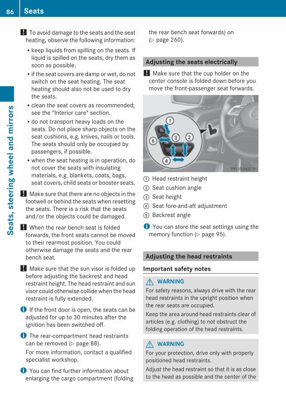
! To avoid damage to the seats and the seatheating, observe the following information:Rkeep liquids from spilling on the seats. Ifliquid is spilled on the seats, dry them assoon as possible.Rif the seat covers are damp or wet, do notswitch on the seat heating. The seatheating should also not be used to drythe seats.Rclean the seat covers as recommended;see the "Interior care" section.Rdo not transport heavy loads on theseats. Do not place sharp objects on theseat cushions, e.g. knives, nails or tools.The seats should only be occupied bypassengers, if possible.Rwhen the seat heating is in operation, donot cover the seats with insulatingmaterials, e.g. blankets, coats, bags,seat covers, child seats or booster seats.
! Make sure that there are no objects in thefootwell or behind the seats when resettingthe seats. There is a risk that the seatsand/or the objects could be damaged.
! When the rear bench seat is foldedforwards, the front seats cannot be movedto their rearmost position. You couldotherwise damage the seats and the rearbench seat.
! Make sure that the sun visor is folded upbefore adjusting the backrest and headrestraint height. The head restraint and sunvisor could otherwise collidewhen the headrestraint is fully extended.
i If the front door is open, the seats can beadjusted for up to 30 minutes after theignition has been switched off.
i The rear-compartment head restraintscan be removed (Y page 88).For more information, contact a qualifiedspecialist workshop.
i You can find further information aboutenlarging the cargo compartment (folding
the rear bench seat forwards) on(Y page 260).
Adjusting the seats electrically! Make sure that the cup holder on thecenter console is folded down before youmove the front-passenger seat forwards.
: Head restraint height; Seat cushion angle= Seat height? Seat fore-and-aft adjustmentA Backrest angle
i You can store the seat settings using thememory function (Y page 95).
Adjusting the head restraints
Important safety notes
G WARNINGFor safety reasons, always drive with the rearhead restraints in the upright position whenthe rear seats are occupied.Keep the area around head restraints clear ofarticles (e.g. clothing) to not obstruct thefolding operation of the head restraints.
G WARNINGFor your protection, drive only with properlypositioned head restraints.Adjust the head restraint so that it is as closeto the head as possible and the center of the
86 SeatsSeats,steerin
gwheelandmirrors
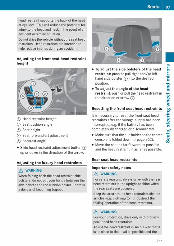
head restraint supports the back of the headat eye level. This will reduce the potential forinjury to the head and neck in the event of anaccident or similar situation.Do not drive the vehicle without the seat headrestraints. Head restraints are intended tohelp reduce injuries during an accident.
Adjusting the front seat head restraintheight
: Head restraint height; Seat cushion angle= Seat height? Seat fore-and-aft adjustmentA Backrest angleX Slide head restraint adjustment button:up or down in the direction of the arrow.
Adjusting the luxury head restraints
G WARNINGWhen folding back the head restraint sidebolsters, do not put your hands between theside bolster and the cushion holder. There isa danger of becoming trapped.
X To adjust the side bolsters of the headrestraint: push or pull right and/or left-hand side bolster: into the desiredposition.
X To adjust the angle of the headrestraint: push or pull the head restraint inthe direction of arrow;.
Resetting the front seat head restraintsIt is necessary to reset the front seat headrestraints after the voltage supply has beeninterrupted, e.g. if the battery has beencompletely discharged or disconnected.X Make sure that the cup holder on the centerconsole is folded down (Y page 262).
X Move the seat as far forward as possibleand the head restraint in as far as possible.
Rear seat head restraints
Important safety notesG WARNINGFor safety reasons, always drive with the rearhead restraints in the upright position whenthe rear seats are occupied.Keep the area around head restraints clear ofarticles (e.g. clothing) to not obstruct thefolding operation of the head restraints.
G WARNINGFor your protection, drive only with properlypositioned head restraints.Adjust the head restraint in such a way that itis as close to the head as possible and the
Seats 87
Seats,steerin
gwheelandmirrors
Z
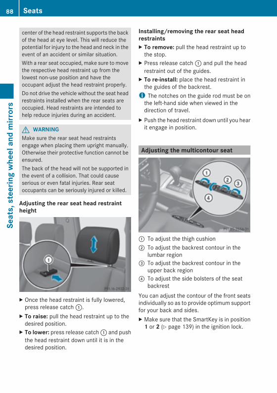
center of the head restraint supports the backof the head at eye level. This will reduce thepotential for injury to the head and neck in theevent of an accident or similar situation.With a rear seat occupied, make sure to movethe respective head restraint up from thelowest non-use position and have theoccupant adjust the head restraint properly.Do not drive the vehicle without the seat headrestraints installed when the rear seats areoccupied. Head restraints are intended tohelp reduce injuries during an accident.
G WARNINGMake sure the rear seat head restraintsengage when placing them upright manually.Otherwise their protective function cannot beensured.The back of the head will not be supported inthe event of a collision. That could causeserious or even fatal injuries. Rear seatoccupants can be seriously injured or killed.
Adjusting the rear seat head restraintheight
X Once the head restraint is fully lowered,press release catch:.
X To raise: pull the head restraint up to thedesired position.
X To lower: press release catch: and pushthe head restraint down until it is in thedesired position.
Installing/removing the rear seat headrestraintsX To remove: pull the head restraint up tothe stop.
X Press release catch: and pull the headrestraint out of the guides.
X To re-install: place the head restraint inthe guides of the backrest.i The notches on the guide rod must be onthe left-hand side when viewed in thedirection of travel.
X Push the head restraint down until you hearit engage in position.
Adjusting the multicontour seat
: To adjust the thigh cushion; To adjust the backrest contour in the
lumbar region= To adjust the backrest contour in the
upper back region? To adjust the side bolsters of the seat
backrestYou can adjust the contour of the front seatsindividually so as to provide optimum supportfor your back and sides.X Make sure that the SmartKey is in position1 or 2 (Y page 139) in the ignition lock.
88 SeatsSeats,steerin
gwheelandmirrors
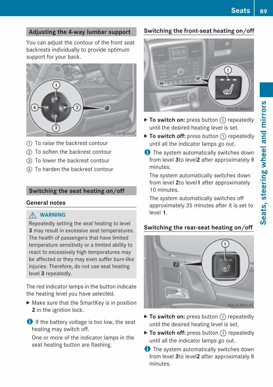
Adjusting the 4-way lumbar supportYou can adjust the contour of the front seatbackrests individually to provide optimumsupport for your back.
: To raise the backrest contour; To soften the backrest contour= To lower the backrest contour? To harden the backrest contour
Switching the seat heating on/off
General notes
G WARNINGRepeatedly setting the seat heating to level3 may result in excessive seat temperatures.The health of passengers that have limitedtemperature sensitivity or a limited ability toreact to excessively high temperatures maybe affected or they may even suffer burn-likeinjuries. Therefore, do not use seat heatinglevel 3 repeatedly.
The red indicator lamps in the button indicatethe heating level you have selected.X Make sure that the SmartKey is in position2 in the ignition lock.
i If the battery voltage is too low, the seatheating may switch off.One or more of the indicator lamps in theseat heating button are flashing.
Switching the front-seat heating on/off
X To switch on: press button: repeatedlyuntil the desired heating level is set.
X To switch off: press button: repeatedlyuntil all the indicator lamps go out.i The system automatically switches downfrom level 3to level2 after approximately 8minutes.The system automatically switches downfrom level 2to level1 after approximately10 minutes.The system automatically switches offapproximately 35 minutes after it is set tolevel 1.
Switching the rear-seat heating on/off
X To switch on: press button: repeatedlyuntil the desired heating level is set.
X To switch off: press button: repeatedlyuntil all the indicator lamps go out.i The system automatically switches downfrom level 3to level2 after approximately 8minutes.
Seats 89
Seats,steerin
gwheelandmirrors
Z
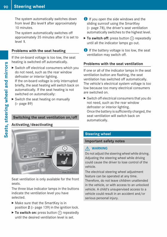
The system automatically switches downfrom level 2to level1 after approximately10 minutes.The system automatically switches offapproximately 35 minutes after it is set tolevel 1.
Problems with the seat heatingIf the on-board voltage is too low, the seatheating is switched off automatically.X Switch off electrical consumers which youdo not need, such as the rear windowdefroster or interior lighting.If the on-board voltage is only interruptedbriefly, the seat heating will switch back onautomatically. If the seat heating is notswitched on automatically:
X Switch the seat heating on manually(Y page 89)
Switching the seat ventilation on/off
Activating/deactivating
Seat ventilation is only available for the frontseats.The three blue indicator lamps in the buttonsindicate the ventilation level you haveselected.X Make sure that the SmartKey is inposition 2 (Y page 139) in the ignition lock.
X To switch on: press button: repeatedlyuntil the desired ventilation level is set.
i If you open the side windows and thesliding sunroof using the SmartKey(Y page 78), the driver's seat ventilationautomatically switches to the highest level.
X To switch off: press button: repeatedlyuntil all the indicator lamps go out.
i If the battery voltage is too low, the seatventilation may switch off.
Problems with the seat ventilationIf one or all of the indicator lamps in the seatventilation button are flashing, the seatventilation has switched off automatically.The vehicle's electrical system voltage is toolow because too many electrical consumersare switched on.X Switch off electrical consumers that you donot need, such as the rear windowdefroster or interior lighting.Once the battery is sufficiently charged, theseat ventilation will switch back onautomatically.
Steering wheel
Important safety notes
G WARNINGDo not adjust the steeringwheel while driving.Adjusting the steering wheel while drivingcould cause the driver to lose control of thevehicle.The electrical steering wheel adjustmentfeature can be operated at any time.Therefore, do not leave children unattendedin the vehicle, or with access to an unlockedvehicle. A child's unsupervised access to avehicle could result in an accident and/orserious personal injury.
90 Steering wheelSeats,steerin
gwheelandmirrors
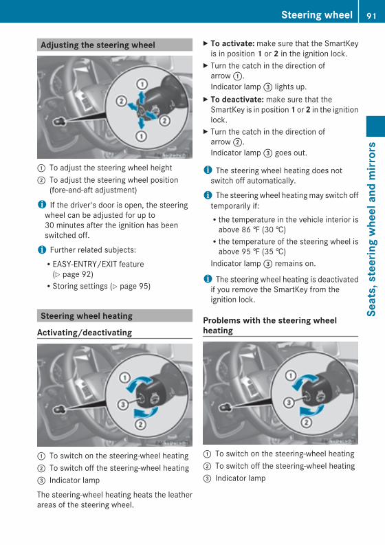
Adjusting the steering wheel
: To adjust the steering wheel height; To adjust the steering wheel position
(fore-and-aft adjustment)
i If the driver's door is open, the steeringwheel can be adjusted for up to30 minutes after the ignition has beenswitched off.
i Further related subjects:REASY-ENTRY/EXIT feature(Y page 92)RStoring settings (Y page 95)
Steering wheel heating
Activating/deactivating
: To switch on the steering-wheel heating; To switch off the steering-wheel heating= Indicator lamp
The steering-wheel heating heats the leatherareas of the steering wheel.
X To activate:make sure that the SmartKeyis in position 1 or 2 in the ignition lock.
X Turn the catch in the direction ofarrow:.Indicator lamp= lights up.
X To deactivate: make sure that theSmartKey is in position1 or2 in the ignitionlock.
X Turn the catch in the direction ofarrow;.Indicator lamp= goes out.
i The steering wheel heating does notswitch off automatically.
i The steering wheel heatingmay switch offtemporarily if:Rthe temperature in the vehicle interior isabove 86 ‡ (30 †)Rthe temperature of the steering wheel isabove 95 ‡ (35 †)
Indicator lamp= remains on.
i The steering wheel heating is deactivatedif you remove the SmartKey from theignition lock.
Problems with the steering wheelheating
: To switch on the steering-wheel heating; To switch off the steering-wheel heating= Indicator lamp
Steering wheel 91
Seats,steerin
gwheelandmirrors
Z
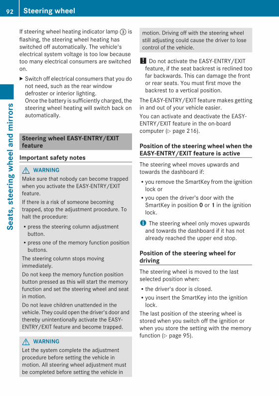
If steering wheel heating indicator lamp= isflashing, the steering wheel heating hasswitched off automatically. The vehicle'selectrical system voltage is too low becausetoo many electrical consumers are switchedon.X Switch off electrical consumers that you donot need, such as the rear windowdefroster or interior lighting.Once the battery is sufficiently charged, thesteering wheel heating will switch back onautomatically.
Steering wheel EASY-ENTRY/EXITfeature
Important safety notes
G WARNINGMake sure that nobody can become trappedwhen you activate the EASY-ENTRY/EXITfeature.If there is a risk of someone becomingtrapped, stop the adjustment procedure. Tohalt the procedure:Rpress the steering column adjustmentbutton.Rpress one of the memory function positionbuttons.
The steering column stops movingimmediately.Do not keep the memory function positionbutton pressed as this will start the memoryfunction and set the steering wheel and seatin motion.Do not leave children unattended in thevehicle. They could open the driver's door andthereby unintentionally activate the EASY-ENTRY/EXIT feature and become trapped.
G WARNINGLet the system complete the adjustmentprocedure before setting the vehicle inmotion. All steering wheel adjustment mustbe completed before setting the vehicle in
motion. Driving off with the steering wheelstill adjusting could cause the driver to losecontrol of the vehicle.
! Do not activate the EASY-ENTRY/EXITfeature, if the seat backrest is reclined toofar backwards. This can damage the frontor rear seats. You must first move thebackrest to a vertical position.
The EASY-ENTRY/EXIT feature makes gettingin and out of your vehicle easier.You can activate and deactivate the EASY-ENTRY/EXIT feature in the on-boardcomputer (Y page 216).
Position of the steering wheel when theEASY-ENTRY/EXIT feature is activeThe steering wheel moves upwards andtowards the dashboard if:Ryou remove the SmartKey from the ignitionlock orRyou open the driver's door with theSmartKey in position 0 or 1 in the ignitionlock.
i The steering wheel only moves upwardsand towards the dashboard if it has notalready reached the upper end stop.
Position of the steering wheel fordrivingThe steering wheel is moved to the lastselected position when:Rthe driver's door is closed.Ryou insert the SmartKey into the ignitionlock.
The last position of the steering wheel isstored when you switch off the ignition orwhen you store the setting with the memoryfunction (Y page 95).
92 Steering wheelSeats,steerin
gwheelandmirrors
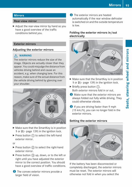
Mirrors
Rear-view mirrorX Adjust the rear-view mirror by hand so youhave a good overview of the trafficconditions behind you.
Exterior mirrors
Adjusting the exterior mirrors
G WARNINGThe exterior mirrors reduce the size of theimage. Objects are actually closer than theyappear. You couldmisjudge the distance fromvehicles driving behind and cause anaccident, e.g. when changing lane. For thisreason, make sure of the actual distance fromthe vehicle driving behind by glancing overyour shoulder.
X Make sure that the SmartKey is in position1 or 2(Y page 139) in the ignition lock.
X Press button: to select the left-handexterior mirror.
orX Press button; to select the right-handexterior mirror.
X Press button= up, down, or to the left orright until you have adjusted the exteriormirror to the correct position. You shouldhave a good overview of traffic conditions.
i The convex exterior mirrors provide alarger field of vision.
i The exterior mirrors are heatedautomatically if the rear window defrosteris switched on and the outside temperatureis low.
Folding the exterior mirrors in/outelectrically
X Make sure that the SmartKey is in position1 or 2(Y page 139) in the ignition lock.
X Briefly press button:.Both exterior mirrors fold in or out.i Make sure that the exterior mirrors arealways folded out fully while driving. Theycould otherwise vibrate.
i If you are driving faster than 9 mph(15 km/h), you can no longer fold in theexterior mirrors.
Setting the exterior mirrors
If the battery has been disconnected orcompletely discharged, the exterior mirrorsmust be reset. The exterior mirrors willotherwise not fold in when you select the
Mirrors 93
Seats,steerin
gwheelandmirrors
Z
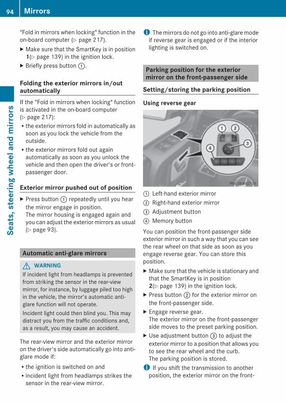
"Fold in mirrors when locking" function in theon-board computer (Y page 217).X Make sure that the SmartKey is in position1(Y page 139) in the ignition lock.
X Briefly press button:.
Folding the exterior mirrors in/outautomaticallyIf the "Fold in mirrors when locking" functionis activated in the on-board computer(Y page 217):Rthe exterior mirrors fold in automatically assoon as you lock the vehicle from theoutside.Rthe exterior mirrors fold out againautomatically as soon as you unlock thevehicle and then open the driver's or front-passenger door.
Exterior mirror pushed out of positionX Press button: repeatedly until you hearthe mirror engage in position.The mirror housing is engaged again andyou can adjust the exterior mirrors as usual(Y page 93).
Automatic anti-glare mirrors
G WARNINGIf incident light from headlamps is preventedfrom striking the sensor in the rear-viewmirror, for instance, by luggage piled too highin the vehicle, the mirror's automatic anti-glare function will not operate.Incident light could then blind you. This maydistract you from the traffic conditions and,as a result, you may cause an accident.
The rear-view mirror and the exterior mirroron the driver's side automatically go into anti-glare mode if:Rthe ignition is switched on andRincident light from headlamps strikes thesensor in the rear-view mirror.
i Themirrors do not go into anti-glaremodeif reverse gear is engaged or if the interiorlighting is switched on.
Parking position for the exteriormirror on the front-passenger side
Setting/storing the parking position
Using reverse gear
: Left-hand exterior mirror; Right-hand exterior mirror= Adjustment button? Memory button
You can position the front-passenger sideexterior mirror in such a way that you can seethe rear wheel on that side as soon as youengage reverse gear. You can store thisposition.X Make sure that the vehicle is stationary andthat the SmartKey is in position2(Y page 139) in the ignition lock.
X Press button; for the exterior mirror onthe front-passenger side.
X Engage reverse gear.The exterior mirror on the front-passengerside moves to the preset parking position.
X Use adjustment button= to adjust theexterior mirror to a position that allows youto see the rear wheel and the curb.The parking position is stored.i If you shift the transmission to anotherposition, the exterior mirror on the front-
94 MirrorsSeats,steerin
gwheelandmirrors
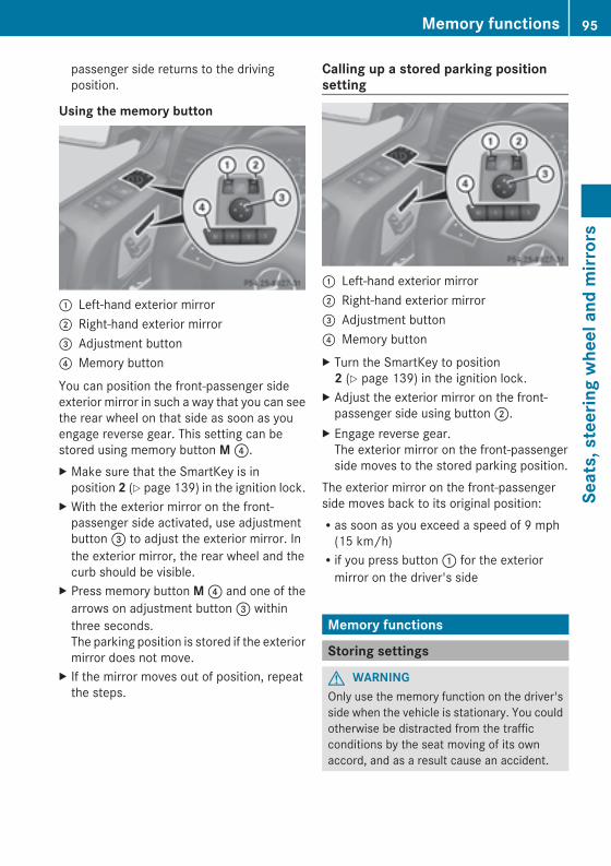
passenger side returns to the drivingposition.
Using the memory button
: Left-hand exterior mirror; Right-hand exterior mirror= Adjustment button? Memory button
You can position the front-passenger sideexterior mirror in such a way that you can seethe rear wheel on that side as soon as youengage reverse gear. This setting can bestored using memory button M?.X Make sure that the SmartKey is inposition 2 (Y page 139) in the ignition lock.
X With the exterior mirror on the front-passenger side activated, use adjustmentbutton= to adjust the exterior mirror. Inthe exterior mirror, the rear wheel and thecurb should be visible.
X Press memory buttonM? and one of thearrows on adjustment button= withinthree seconds.The parking position is stored if the exteriormirror does not move.
X If the mirror moves out of position, repeatthe steps.
Calling up a stored parking positionsetting
: Left-hand exterior mirror; Right-hand exterior mirror= Adjustment button? Memory buttonX Turn the SmartKey to position2 (Y page 139) in the ignition lock.
X Adjust the exterior mirror on the front-passenger side using button;.
X Engage reverse gear.The exterior mirror on the front-passengerside moves to the stored parking position.
The exterior mirror on the front-passengerside moves back to its original position:Ras soon as you exceed a speed of 9 mph(15 km/h)Rif you press button: for the exteriormirror on the driver's side
Memory functions
Storing settings
G WARNINGOnly use the memory function on the driver'sside when the vehicle is stationary. You couldotherwise be distracted from the trafficconditions by the seat moving of its ownaccord, and as a result cause an accident.
Memory functions 95
Seats,steerin
gwheelandmirrors
Z
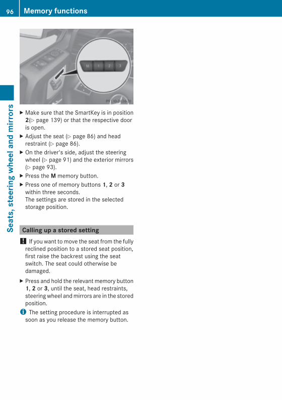
X Make sure that the SmartKey is in position2(Y page 139) or that the respective dooris open.
X Adjust the seat (Y page 86) and headrestraint (Y page 86).
X On the driver's side, adjust the steeringwheel (Y page 91) and the exterior mirrors(Y page 93).
X Press the M memory button.X Press one of memory buttons 1, 2 or 3within three seconds.The settings are stored in the selectedstorage position.
Calling up a stored setting! If you want to move the seat from the fullyreclined position to a stored seat position,first raise the backrest using the seatswitch. The seat could otherwise bedamaged.
X Press and hold the relevant memory button1, 2 or 3, until the seat, head restraints,steeringwheel andmirrors are in the storedposition.i The setting procedure is interrupted assoon as you release the memory button.
96 Memory functionsSeats,steerin
gwheelandmirrors
Useful information .............................. 98Exterior lighting .................................. 98Interior lighting ................................. 105Replacing bulbs ................................. 108Windshield wipers ............................ 114
97
Lightsandwindshieldwipers

Useful information
i This Operator's Manual describes allmodels and all standard and optionalequipment of your vehicle available at thetime of publication of the Operator'sManual. Country-specific differences arepossible. Please note that your vehicle maynot be equipped with all featuresdescribed. This also applies to safety-related systems and functions.
i Read the information on qualifiedspecialist workshops: (Y page 24).
Exterior lighting
Important safety notesFor reasons of safety, Mercedes-Benzrecommends that you drive with the lightsswitched on even during the daytime. In somecountries, operation of the headlamps variesdue to legal requirements and self-imposedobligations.
Driving abroad
Conversion to symmetrical low beamSwitch the headlamps to symmetrical lowbeam in countries in which traffic drives onthe opposite side of the road from the countrywhere the vehicle is registered. This preventsglare to oncoming traffic. When usingsymmetrical lights, the edge of the road is notlit as widely and as far ahead as normal.Have the headlamps converted at a qualifiedspecialist workshop as close to the border aspossible before driving in these countries.
Conversion to asymmetrical low beamafter returningHave the headlamps converted back toasymmetrical low-beam headlamps at aqualified specialist workshop as soon aspossible after crossing the border again.
Light switch
Operation! Switch off the parking lamps and low-beam headlamps when you leave thevehicle. This prevents the battery fromdischarging.
! If the battery has been excessivelydischarged, the parking lamps or standinglamps are automatically switched off toenable the next engine start. Always parkyour vehicle safely and sufficiently litaccording to legal standards. Avoid thecontinuous use of the T parking lampsfor several hours. If possible, switch on theX right or the W left standing lamp.
1W Left-hand standing lamps2X Right-hand standing lamps3T Parking lamps, side marker lamps,
license plate and instrument clusterlighting
4Ã Automatic headlamp mode/daytimerunning lamps
5L Low-beam/high-beam headlamps
If you hear a warning tone when you leave thevehicle, the lights may still be switched on.X Turn the light switch toÃ.The turn signals, high-beam headlamps andthe high-beam flasher are operated using thecombination switch (Y page 103).
98 Exterior lightingLightsandwindshieldwipers
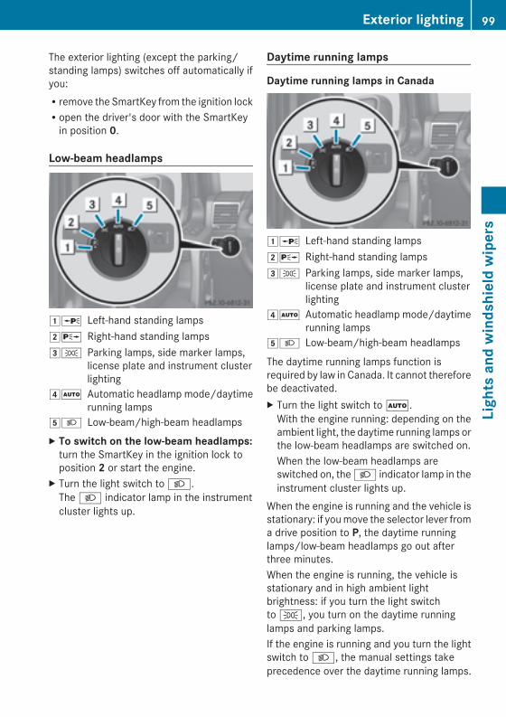
The exterior lighting (except the parking/standing lamps) switches off automatically ifyou:Rremove the SmartKey from the ignition lockRopen the driver's door with the SmartKeyin position 0.
Low-beam headlamps
1W Left-hand standing lamps2X Right-hand standing lamps3T Parking lamps, side marker lamps,
license plate and instrument clusterlighting
4Ã Automatic headlamp mode/daytimerunning lamps
5L Low-beam/high-beam headlampsX To switch on the low-beam headlamps:turn the SmartKey in the ignition lock toposition 2 or start the engine.
X Turn the light switch to L.The L indicator lamp in the instrumentcluster lights up.
Daytime running lamps
Daytime running lamps in Canada
1W Left-hand standing lamps2X Right-hand standing lamps3T Parking lamps, side marker lamps,
license plate and instrument clusterlighting
4Ã Automatic headlamp mode/daytimerunning lamps
5L Low-beam/high-beam headlamps
The daytime running lamps function isrequired by law in Canada. It cannot thereforebe deactivated.X Turn the light switch toÃ.With the engine running: depending on theambient light, the daytime running lamps orthe low-beam headlamps are switched on.When the low-beam headlamps areswitched on, the L indicator lamp in theinstrument cluster lights up.
When the engine is running and the vehicle isstationary: if youmove the selector lever froma drive position to P, the daytime runninglamps/low-beam headlamps go out afterthree minutes.When the engine is running, the vehicle isstationary and in high ambient lightbrightness: if you turn the light switchto T, you turn on the daytime runninglamps and parking lamps.If the engine is running and you turn the lightswitch to L, the manual settings takeprecedence over the daytime running lamps.
Exterior lighting 99
Lightsandwindshieldwipers
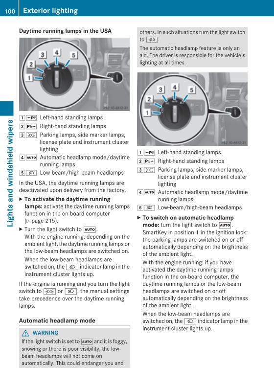
Daytime running lamps in the USA
1W Left-hand standing lamps2X Right-hand standing lamps3T Parking lamps, side marker lamps,
license plate and instrument clusterlighting
4Ã Automatic headlamp mode/daytimerunning lamps
5L Low-beam/high-beam headlamps
In the USA, the daytime running lamps aredeactivated upon delivery from the factory.X To activate the daytime runninglamps: activate the daytime running lampsfunction in the on-board computer(Y page 215).
X Turn the light switch toÃ.With the engine running: depending on theambient light, the daytime running lamps orthe low-beam headlamps are switched on.When the low-beam headlamps areswitched on, the L indicator lamp in theinstrument cluster lights up.
If the engine is running and you turn the lightswitch to T or L, the manual settingstake precedence over the daytime runninglamps.
Automatic headlamp mode
G WARNINGIf the light switch is set toà and it is foggy,snowing or there is poor visibility, the low-beam headlamps will not come onautomatically. This could endanger you and
others. In such situations turn the light switchto L.The automatic headlamp feature is only anaid. The driver is responsible for the vehicle'slighting at all times.
1W Left-hand standing lamps2X Right-hand standing lamps3T Parking lamps, side marker lamps,
license plate and instrument clusterlighting
4Ã Automatic headlamp mode/daytimerunning lamps
5L Low-beam/high-beam headlampsX To switch on automatic headlampmode: turn the light switch toÃ.SmartKey in position 1 in the ignition lock:the parking lamps are switched on or offautomatically depending on the brightnessof the ambient light.With the engine running: if you haveactivated the daytime running lampsfunction in the on-board computer, thedaytime running lamps or the low-beamheadlamps are switched on or offautomatically depending on the brightnessof the ambient light.When the low-beam headlamps areswitched on, the L indicator lamp in theinstrument cluster lights up.
100 Exterior lightingLightsandwindshieldwipers
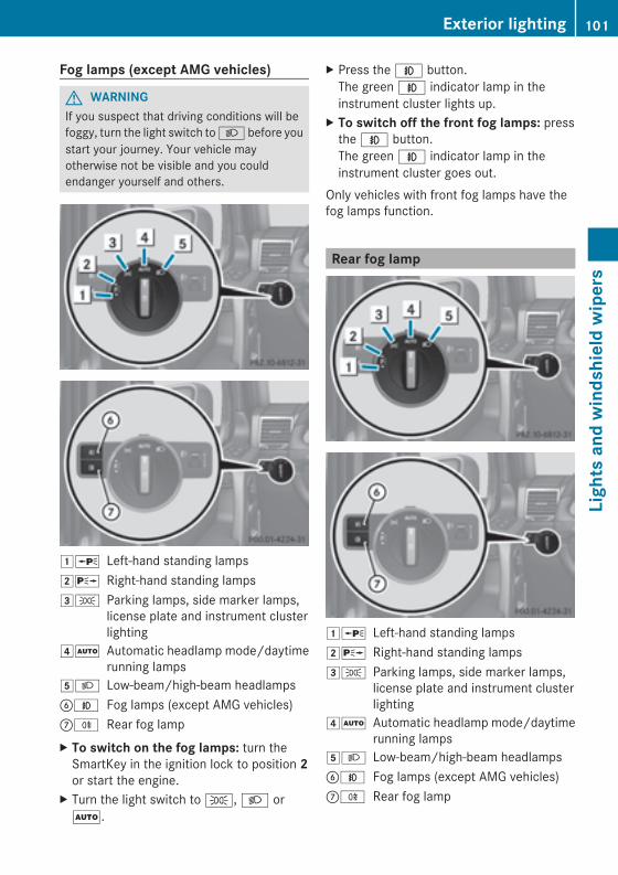
Fog lamps (except AMG vehicles)
G WARNINGIf you suspect that driving conditions will befoggy, turn the light switch toL before youstart your journey. Your vehicle mayotherwise not be visible and you couldendanger yourself and others.
1W Left-hand standing lamps2X Right-hand standing lamps3T Parking lamps, side marker lamps,
license plate and instrument clusterlighting
4Ã Automatic headlamp mode/daytimerunning lamps
5L Low-beam/high-beam headlampsBN Fog lamps (except AMG vehicles)CR Rear fog lampX To switch on the fog lamps: turn theSmartKey in the ignition lock to position 2or start the engine.
X Turn the light switch to T, L orÃ.
X Press the N button.The green N indicator lamp in theinstrument cluster lights up.
X To switch off the front fog lamps: pressthe N button.The green N indicator lamp in theinstrument cluster goes out.
Only vehicles with front fog lamps have thefog lamps function.
Rear fog lamp
1W Left-hand standing lamps2X Right-hand standing lamps3T Parking lamps, side marker lamps,
license plate and instrument clusterlighting
4Ã Automatic headlamp mode/daytimerunning lamps
5L Low-beam/high-beam headlampsBN Fog lamps (except AMG vehicles)CR Rear fog lamp
Exterior lighting 101
Lightsandwindshieldwipers
Z
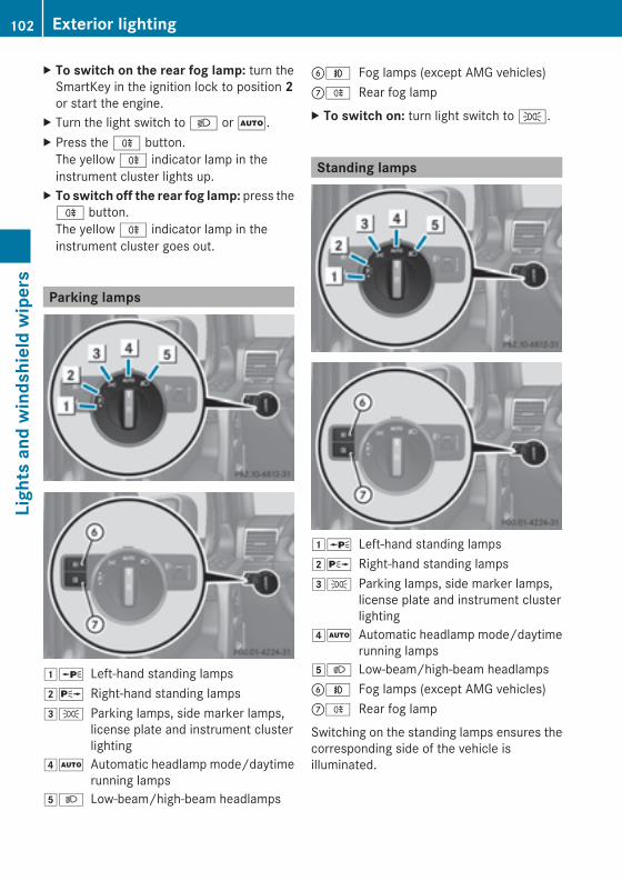
X To switch on the rear fog lamp: turn theSmartKey in the ignition lock to position 2or start the engine.
X Turn the light switch to L orÃ.X Press the R button.The yellow R indicator lamp in theinstrument cluster lights up.
X To switch off the rear fog lamp: press theR button.The yellow R indicator lamp in theinstrument cluster goes out.
Parking lamps
1W Left-hand standing lamps2X Right-hand standing lamps3T Parking lamps, side marker lamps,
license plate and instrument clusterlighting
4Ã Automatic headlamp mode/daytimerunning lamps
5L Low-beam/high-beam headlamps
BN Fog lamps (except AMG vehicles)CR Rear fog lampX To switch on: turn light switch to T.
Standing lamps
1W Left-hand standing lamps2X Right-hand standing lamps3T Parking lamps, side marker lamps,
license plate and instrument clusterlighting
4Ã Automatic headlamp mode/daytimerunning lamps
5L Low-beam/high-beam headlampsBN Fog lamps (except AMG vehicles)CR Rear fog lamp
Switching on the standing lamps ensures thecorresponding side of the vehicle isilluminated.
102 Exterior lightingLightsandwindshieldwipers
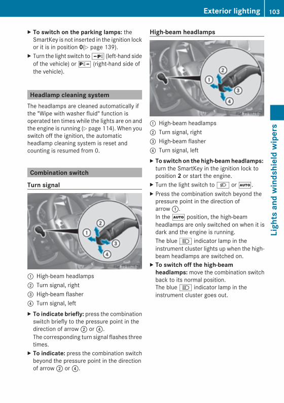
X To switch on the parking lamps: theSmartKey is not inserted in the ignition lockor it is in position 0(Y page 139).
X Turn the light switch toW (left-hand sideof the vehicle) or X (right-hand side ofthe vehicle).
Headlamp cleaning systemThe headlamps are cleaned automatically ifthe "Wipe with washer fluid" function isoperated ten times while the lights are on andthe engine is running (Y page 114). When youswitch off the ignition, the automaticheadlamp cleaning system is reset andcounting is resumed from 0.
Combination switch
Turn signal
: High-beam headlamps; Turn signal, right= High-beam flasher? Turn signal, leftX To indicate briefly: press the combinationswitch briefly to the pressure point in thedirection of arrow; or?.The corresponding turn signal flashes threetimes.
X To indicate: press the combination switchbeyond the pressure point in the directionof arrow; or?.
High-beam headlamps
: High-beam headlamps; Turn signal, right= High-beam flasher? Turn signal, leftX To switch on the high-beamheadlamps:turn the SmartKey in the ignition lock toposition 2 or start the engine.
X Turn the light switch to L orÃ.X Press the combination switch beyond thepressure point in the direction ofarrow:.In theà position, the high-beamheadlamps are only switched on when it isdark and the engine is running.The blue K indicator lamp in theinstrument cluster lights up when the high-beam headlamps are switched on.
X To switch off the high-beamheadlamps:move the combination switchback to its normal position.The blue K indicator lamp in theinstrument cluster goes out.
Exterior lighting 103
Lightsandwindshieldwipers
Z
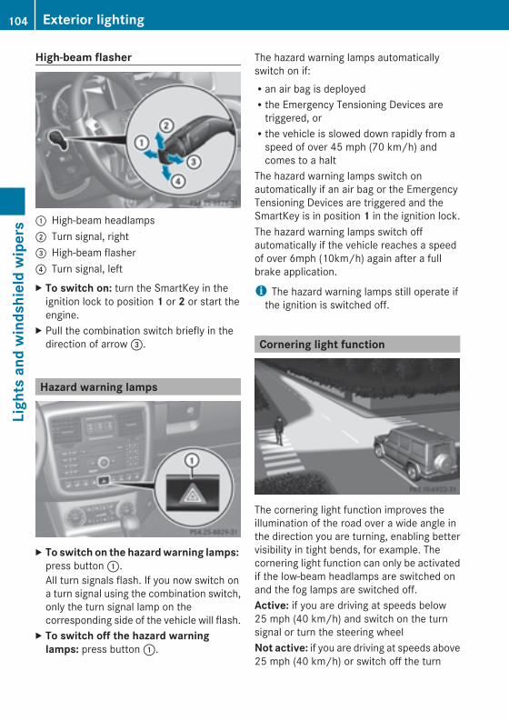
High-beam flasher
: High-beam headlamps; Turn signal, right= High-beam flasher? Turn signal, leftX To switch on: turn the SmartKey in theignition lock to position 1 or 2 or start theengine.
X Pull the combination switch briefly in thedirection of arrow=.
Hazard warning lamps
X To switch on the hazardwarning lamps:press button:.All turn signals flash. If you now switch ona turn signal using the combination switch,only the turn signal lamp on thecorresponding side of the vehicle will flash.
X To switch off the hazard warninglamps: press button:.
The hazard warning lamps automaticallyswitch on if:Ran air bag is deployedRthe Emergency Tensioning Devices aretriggered, orRthe vehicle is slowed down rapidly from aspeed of over 45 mph (70 km/h) andcomes to a halt
The hazard warning lamps switch onautomatically if an air bag or the EmergencyTensioning Devices are triggered and theSmartKey is in position 1 in the ignition lock.The hazard warning lamps switch offautomatically if the vehicle reaches a speedof over 6mph (10km/h) again after a fullbrake application.
i The hazard warning lamps still operate ifthe ignition is switched off.
Cornering light function
The cornering light function improves theillumination of the road over a wide angle inthe direction you are turning, enabling bettervisibility in tight bends, for example. Thecornering light function can only be activatedif the low-beam headlamps are switched onand the fog lamps are switched off.Active: if you are driving at speeds below25 mph (40 km/h) and switch on the turnsignal or turn the steering wheelNot active: if you are driving at speeds above25 mph (40 km/h) or switch off the turn
104 Exterior lightingLightsandwindshieldwipers
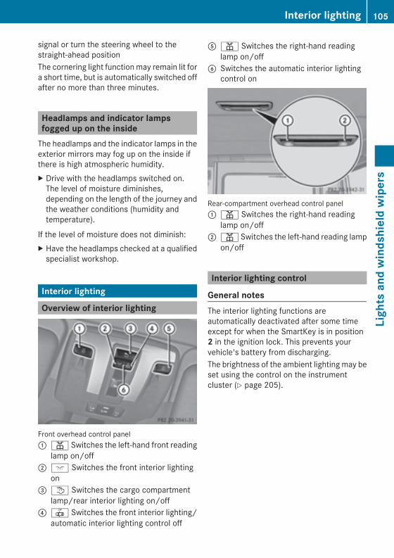
signal or turn the steering wheel to thestraight-ahead positionThe cornering light function may remain lit fora short time, but is automatically switched offafter no more than three minutes.
Headlamps and indicator lampsfogged up on the insideThe headlamps and the indicator lamps in theexterior mirrors may fog up on the inside ifthere is high atmospheric humidity.X Drive with the headlamps switched on.The level of moisture diminishes,depending on the length of the journey andthe weather conditions (humidity andtemperature).
If the level of moisture does not diminish:X Have the headlamps checked at a qualifiedspecialist workshop.
Interior lighting
Overview of interior lighting
Front overhead control panel: p Switches the left-hand front reading
lamp on/off; c Switches the front interior lighting
on= t Switches the cargo compartment
lamp/rear interior lighting on/off? | Switches the front interior lighting/
automatic interior lighting control off
A p Switches the right-hand readinglamp on/off
B Switches the automatic interior lightingcontrol on
Rear-compartment overhead control panel: p Switches the right-hand reading
lamp on/off; p Switches the left-hand reading lamp
on/off
Interior lighting control
General notesThe interior lighting functions areautomatically deactivated after some timeexcept for when the SmartKey is in position2 in the ignition lock. This prevents yourvehicle's battery from discharging.The brightness of the ambient lightingmay beset using the control on the instrumentcluster (Y page 205).
Interior lighting 105
Lightsandwindshieldwipers
Z
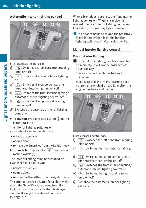
Automatic interior lighting control
Front overhead control panel: p Switches the left-hand front reading
lamp on/off; c Switches the front interior lighting
on= t Switches the cargo compartment
lamp/rear interior lighting on/off? | Switches the front interior lighting/
automatic interior lighting control offA p Switches the right-hand reading
lamp on/offB Switches the automatic interior lighting
control onX To switch on: set rocker switchB to thecenter position.
The interior lighting switches onautomatically when it is dark if you:Runlock the vehicleRopen a doorRremove the SmartKey from the ignition lockX To switch off: press the | symbol onrocker switchB.
The interior lighting remains switched offeven when it is dark if you:Runlock the vehicleRopen a door.Rremove the SmartKey from the ignition lockThe interior light is activated for a short whilewhen the SmartKey is removed from theignition lock. You can activate this delayedswitch-off using the on-board computer(Y page 216).
When a front door is opened, the front interiorlighting comes on. When a rear door isopened, the rear interior lighting comes on.In addition, the courtesy lights come on.
i If a door remains open and the SmartKeyis not in the ignition lock, the interiorlighting switches off after a short while.
Manual interior lighting control
Front interior lighting! If the interior lighting has been switchedon manually, it will not be switched offautomatically.This can cause the starter battery todischarge.Make sure that the interior lighting doesnot remain switched on too long after theengine has been switched off.
Front overhead control panel: p Switches the left-hand front reading
lamp on/off; c Switches the front interior lighting
on= t Switches the cargo compartment
lamp/rear interior lighting on/off? | Switches the front interior lighting/
automatic interior lighting control offA p Switches the right-hand reading
lamp on/offB Switches the automatic interior lighting
control on
106 Interior lightingLightsandwindshieldwipers
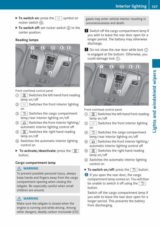
X To switch on: press the c symbol onrocker switchB.
X To switch off: set rocker switchB to thecenter position.
Reading lamps
Front overhead control panel: p Switches the left-hand front reading
lamp on/off; c Switches the front interior lighting
on= t Switches the cargo compartment
lamp/rear interior lighting on/off? | Switches the front interior lighting/
automatic interior lighting control offA p Switches the right-hand reading
lamp on/offB Switches the automatic interior lighting
control onX To activate/deactivate: press the pbutton.
Cargo compartment lampG WARNINGTo prevent possible personal injury, alwayskeep hands and fingers away from the cargocompartment opening when closing thetailgate. Be especially careful when smallchildren are around.
G WARNINGMake sure the tailgate is closed when theengine is running and while driving. Amongother dangers, deadly carbon monoxide (CO)
gases may enter vehicle interior resulting inunconsciousness and death.
! Switch off the cargo compartment lamp ifyou wish to leave the rear door open for alonger period. The battery may otherwisedischarge.
! Do not close the rear door while lock:is engaged at the bottom. Otherwise, youcould damage lock:.
Front overhead control panel: p Switches the left-hand front reading
lamp on/off; c Switches the front interior lighting
on= t Switches the cargo compartment
lamp/rear interior lighting on/off? | Switches the front interior lighting/
automatic interior lighting control offA p Switches the right-hand reading
lamp on/offB Switches the automatic interior lighting
control onX To switch on/off: press the t button.i If you open the rear door, the cargocompartment lamp comes on. You will thenbe unable to switch it off using the tbutton.Switch off the cargo compartment lamp ifyou wish to leave the rear door open for alonger period. This prevents the batteryfrom discharging.
Interior lighting 107
Lightsandwindshieldwipers
Z
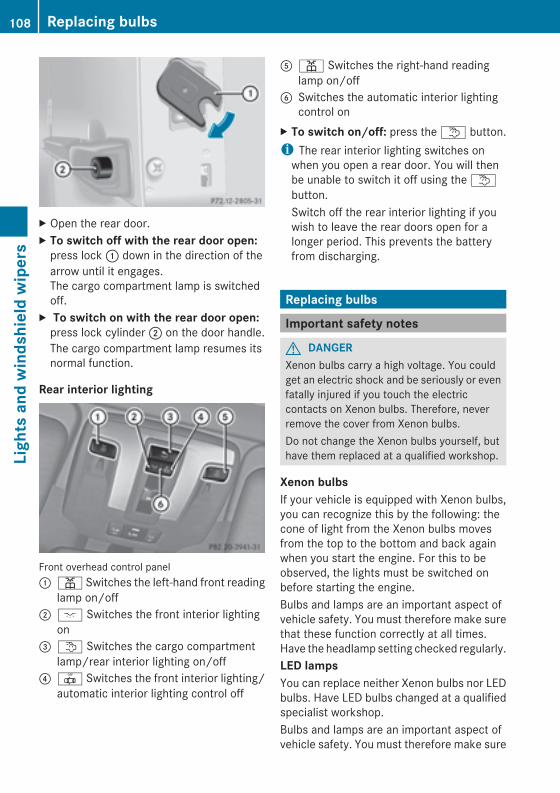
X Open the rear door.X To switch off with the rear door open:press lock: down in the direction of thearrow until it engages.The cargo compartment lamp is switchedoff.
X To switch on with the rear door open:press lock cylinder; on the door handle.The cargo compartment lamp resumes itsnormal function.
Rear interior lighting
Front overhead control panel: p Switches the left-hand front reading
lamp on/off; c Switches the front interior lighting
on= t Switches the cargo compartment
lamp/rear interior lighting on/off? | Switches the front interior lighting/
automatic interior lighting control off
A p Switches the right-hand readinglamp on/off
B Switches the automatic interior lightingcontrol on
X To switch on/off: press the t button.i The rear interior lighting switches onwhen you open a rear door. You will thenbe unable to switch it off using the tbutton.Switch off the rear interior lighting if youwish to leave the rear doors open for alonger period. This prevents the batteryfrom discharging.
Replacing bulbs
Important safety notes
G DANGERXenon bulbs carry a high voltage. You couldget an electric shock and be seriously or evenfatally injured if you touch the electriccontacts on Xenon bulbs. Therefore, neverremove the cover from Xenon bulbs.Do not change the Xenon bulbs yourself, buthave them replaced at a qualified workshop.
Xenon bulbsIf your vehicle is equipped with Xenon bulbs,you can recognize this by the following: thecone of light from the Xenon bulbs movesfrom the top to the bottom and back againwhen you start the engine. For this to beobserved, the lights must be switched onbefore starting the engine.Bulbs and lamps are an important aspect ofvehicle safety. You must therefore make surethat these function correctly at all times.Have the headlamp setting checked regularly.LED lampsYou can replace neither Xenon bulbs nor LEDbulbs. Have LED bulbs changed at a qualifiedspecialist workshop.Bulbs and lamps are an important aspect ofvehicle safety. You must therefore make sure
108 Replacing bulbsLightsandwindshieldwipers
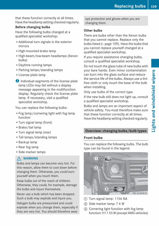
that these function correctly at all times.Have the headlamp setting checked regularly.Before changing bulbsHave the following bulbs changed at aqualified specialist workshop:RAdditional turn signals in the exteriormirrorsRHigh-mounted brake lampRHigh-beam/low-beam headlamps (Xenonbulbs)RDaytime running lampsRParking lamps/standing lampsRLicense plate lamp
i Individual segments of the license platelamp LEDs may fail without a displaymessage appearing in the multifunctiondisplay. Regularly check the license platelamp. If necessary, visit a qualifiedspecialist workshop.
You can replace the following bulbs:RFog lamp/cornering light with fog lampfunctionRTurn signal lamp (front)RBrake/tail lampRTurn signal lamp (rear)RTail lamps/standing lampsRBackup lampRRear fog lampRSide marker lamps
G WARNINGBulbs and lamps can become very hot. Forthis reason, allow them to cool down beforechanging them. Otherwise, you could burnyourself when you touch them.Keep bulbs out of the reach of children.Otherwise, they could, for example, damagethe bulbs and injure themselves.Never use a bulb which has been dropped.Such a bulb may explode and injure you.Halogen bulbs are pressurized and couldexplode when you change them, especially ifthey are very hot. You should therefore wear
eye protection and gloves when you arechanging them.
Other bulbsThere are bulbs other than the Xenon bulbsthat you cannot replace. Replace only thebulbs listed (Y page 109). Have the bulbs thatyou cannot replace yourself changed at aqualified specialist workshop.If you require assistance changing bulbs,consult a qualified specialist workshop.Do not touch the glass tube of new bulbs withyour bare hands. Even minor contaminationcan burn into the glass surface and reducethe service life of the bulbs. Always use a lint-free cloth or only touch the base of the bulbwhen installing.Only use bulbs of the correct type.If the new bulb still does not light up, consulta qualified specialist workshop.Bulbs and lamps are an important aspect ofvehicle safety. You must therefore make surethat these function correctly at all times.Have the headlamp setting checked regularly.
Overview: changing bulbs/bulb types
Front bulbsYou can replace the following bulbs. The bulbtype can be found in the legend.
: Turn signal lamp: 1156 NA; Side marker lamp: T 4 W= Cornering light function with fog lamp
function: H1155W (except AMGvehicles)
Replacing bulbs 109
Lightsandwindshieldwipers
Z
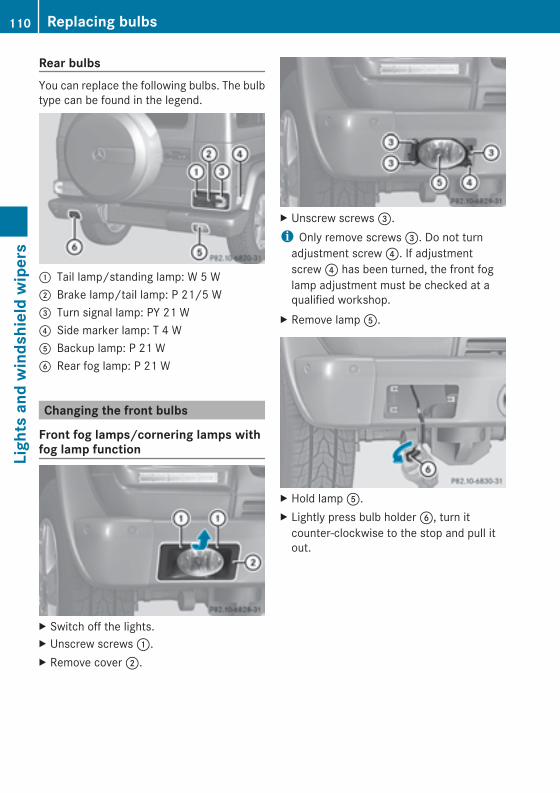
Rear bulbsYou can replace the following bulbs. The bulbtype can be found in the legend.
: Tail lamp/standing lamp: W 5 W; Brake lamp/tail lamp: P 21/5 W= Turn signal lamp: PY 21 W? Side marker lamp: T 4 WA Backup lamp: P 21 WB Rear fog lamp: P 21 W
Changing the front bulbs
Front fog lamps/cornering lamps withfog lamp function
X Switch off the lights.X Unscrew screws:.X Remove cover;.
X Unscrew screws=.i Only remove screws=. Do not turnadjustment screw?. If adjustmentscrew? has been turned, the front foglamp adjustment must be checked at aqualified workshop.
X Remove lampA.
X Hold lampA.X Lightly press bulb holderB, turn itcounter-clockwise to the stop and pull itout.
110 Replacing bulbsLightsandwindshieldwipers
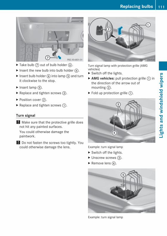
X Take bulbC out of bulb holderB.X Insert the new bulb into bulb holderB.X Insert bulb holderB into lampA and turnit clockwise to the stop.
X Insert lampA.X Replace and tighten screws=.
X Position cover;.X Replace and tighten screws:.
Turn signal! Make sure that the protective grille doesnot hit any painted surfaces.You could otherwise damage thepaintwork.
! Do not fasten the screws too tightly. Youcould otherwise damage the lens.
Turn signal lamp with protection grille (AMGvehicles)X Switch off the lights.X AMG vehicles: pull protection grille: inthe direction of the arrow out ofmounting;.
X Fold up protection grille:.
Example: turn signal lampX Switch off the lights.X Unscrew screws=.X Remove lens?.
Example: turn signal lamp
Replacing bulbs 111
Lightsandwindshieldwipers
Z
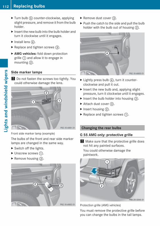
X Turn bulbA counter-clockwise, applyingslight pressure, and remove it from the bulbholder.
X Insert the new bulb into the bulb holder andturn it clockwise until it engages.
X Install lens?.X Replace and tighten screws=.
X AMG vehicles: fold down protectiongrille: and allow it to engage inmounting;.
Side marker lamps! Do not fasten the screws too tightly. Youcould otherwise damage the lens.
Front side marker lamp (example)
The bulbs of the front and rear side markerlamps are changed in the same way.X Switch off the lights.X Unscrew screws:.X Remove housing;.
X Remove dust cover=.X Push the catch to the side and pull the bulbholder with the bulb out of housing;.
X Lightly press bulb?, turn it counter-clockwise and pull it out.
X Insert the new bulb and, applying slightpressure, turn it clockwise until it engages.
X Insert the bulb holder into housing;.X Attach dust cover=.X Insert housing;.X Replace and tighten screws:.
Changing the rear bulbs
G 55 AMG only: protective grille! Make sure that the protective grille doesnot hit any painted surfaces.You could otherwise damage thepaintwork.
Protection grille (AMG vehicles)
You must remove the protective grille beforeyou can change the bulbs in the tail lamps.
112 Replacing bulbsLightsandwindshieldwipers
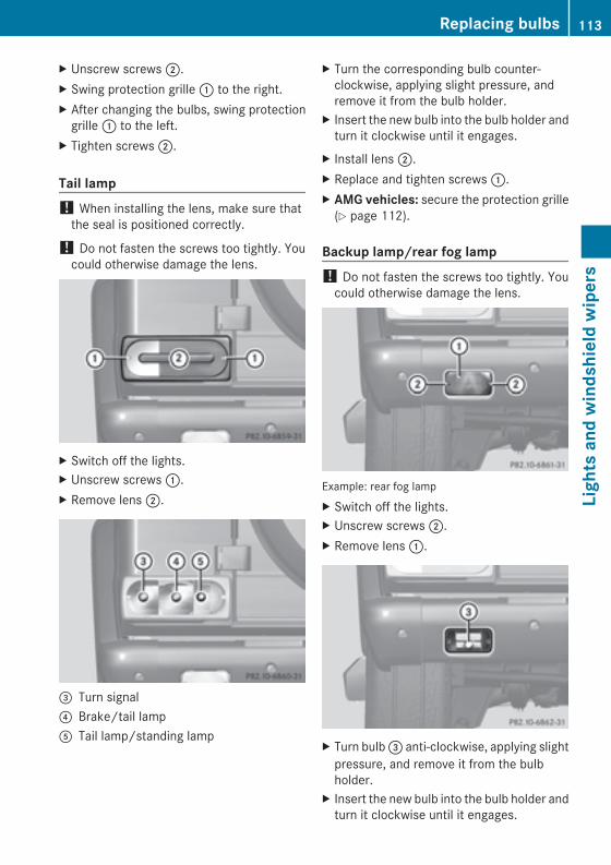
X Unscrew screws;.X Swing protection grille: to the right.X After changing the bulbs, swing protectiongrille: to the left.
X Tighten screws;.
Tail lamp! When installing the lens, make sure thatthe seal is positioned correctly.
! Do not fasten the screws too tightly. Youcould otherwise damage the lens.
X Switch off the lights.X Unscrew screws:.X Remove lens;.
= Turn signal? Brake/tail lampA Tail lamp/standing lamp
X Turn the corresponding bulb counter-clockwise, applying slight pressure, andremove it from the bulb holder.
X Insert the new bulb into the bulb holder andturn it clockwise until it engages.
X Install lens;.X Replace and tighten screws:.X AMG vehicles: secure the protection grille(Y page 112).
Backup lamp/rear fog lamp! Do not fasten the screws too tightly. Youcould otherwise damage the lens.
Example: rear fog lampX Switch off the lights.X Unscrew screws;.X Remove lens:.
X Turn bulb= anti-clockwise, applying slightpressure, and remove it from the bulbholder.
X Insert the new bulb into the bulb holder andturn it clockwise until it engages.
Replacing bulbs 113
Lightsandwindshieldwipers
Z
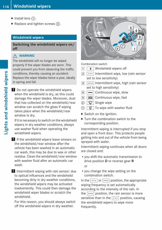
X Install lens:.X Replace and tighten screws;.
Windshield wipers
Switching the windshield wipers on/off
G WARNINGThe windshield will no longer be wipedproperly if the wiper blades are worn. Thiscould prevent you from observing the trafficconditions, thereby causing an accident.Replace the wiper blades twice a year, ideallyin spring and fall.
! Do not operate the windshield wiperswhen the windshield is dry, as this coulddamage the wiper blades. Moreover, dustthat has collected on the windshield/rearwindow can scratch the glass if wipingtakes place when the windshield/rearwindow is dry.If it is necessary to switch on thewindshieldwipers in dry weather conditions, alwaysuse washer fluid when operating thewindshield wipers.
! If the windshield wipers leave smears onthe windshield/rear window after thevehicle has been washed in an automaticcar wash, this may be due to wax or otherresidue. Clean the windshield/rear windowwith washer fluid after an automatic carwash.
! Intermittent wiping with rain sensor: dueto optical influences and the windshieldbecoming dirty in dry weather conditions,the windshield wipers may be activatedinadvertently. This could then damage thewindshield wiper blades or scratch thewindshield.For this reason, you should always switchoff the windshield wipers in dry weather.
Combination switch1 $ Windshield wipers off2 Ä Intermittent wipe, low (rain sensor
set to low sensitivity)3 Å Intermittent wipe, high (rain sensor
set to high sensitivity)4 ° Continuous wipe, slow5 ¯ Continuous wipe, fastB í Single wipeC î To wipe with washer fluidX Switch on the ignition.X Turn the combination switch to thecorresponding position.
Intermittent wiping is interrupted if you stopand open a front door. This protects peoplegetting into and out of the vehicle from beingsprayed with water.Intermittent wiping continues when all doorsare closed and:Ryou shift the automatic transmission todrive position D or reverse gear RorRyou change the wipe setting on thecombination switch.
In the Ä or Å position, the appropriatewiping frequency is set automaticallyaccording to the intensity of the rain. Inthe Å position, the rain sensor is moresensitive than in the Ä position, causingthe windshield wipers to wipe morefrequently.
114 Windshield wipersLightsandwindshieldwipers
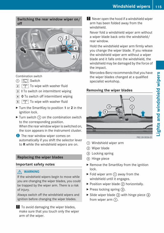
Switching the rear window wiper on/off
Combination switch: è Switch2 b To wipe with washer fluid3 I To switch on intermittent wiping4 0 To switch off intermittent wiping5 b To wipe with washer fluidX Turn the SmartKey to position 1 or 2 in theignition lock.
X Turn switch: on the combination switchto the corresponding position.When the rearwindowwiper is switched on,the icon appears in the instrument cluster.i The rear window wiper comes onautomatically if you shift the selector leverto R while the windshield wipers are on.
Replacing the wiper blades
Important safety notes
G WARNINGIf the windshield wipers begin to move whileyou are changing the wiper blades, you couldbe trapped by the wiper arm. There is a riskof injury.Always switch off the windshield wipers andignition before changing the wiper blades.
! To avoid damaging the wiper blades,make sure that you touch only the wiperarm of the wiper.
! Never open the hood if a windshield wiperarm has been folded away from thewindshield.Never fold a windshield wiper arm withouta wiper blade back onto the windshield/rear window.Hold the windshield wiper arm firmly whenyou change the wiper blade. If you releasethe windshield wiper arm without a wiperblade and it falls onto the windshield, thewindshield may be damaged by the force ofthe impact.Mercedes-Benz recommends that you havethe wiper blades changed at a qualifiedspecialist workshop.
Removing the wiper blades
: Windshield wiper arm; Wiper blade= Locking spring? Hinge pieceX Remove the SmartKey from the ignitionlock.
X Fold wiper arm: away from thewindshield until it engages.
X Position wiper blade; horizontally.X Press locking spring=.X Slide wiper blade; with hinge piece?from wiper arm:.
Windshield wipers 115
Lightsandwindshieldwipers
Z
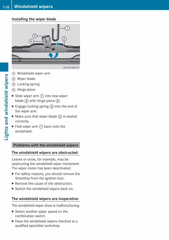
Installing the wiper blade
: Windshield wiper arm; Wiper blade= Locking spring? Hinge pieceX Slide wiper arm: into new wiperblade; with hinge piece?.
X Engage locking spring= into the end ofthe wiper arm.
X Make sure that wiper blade; is seatedcorrectly.
X Fold wiper arm: back onto thewindshield.
Problems with the windshield wipers
The windshield wipers are obstructedLeaves or snow, for example, may beobstructing the windshield wiper movement.The wiper motor has been deactivated.X For safety reasons, you should remove theSmartKey from the ignition lock.
X Remove the cause of the obstruction.X Switch the windshield wipers back on.
The windshield wipers are inoperativeThe windshield wiper drive is malfunctioning.X Select another wiper speed on thecombination switch.
X Have the windshield wipers checked at aqualified specialist workshop.
116 Windshield wipersLightsandwindshieldwipers
Useful information ............................ 118Overview of climate control sys-tems ................................................... 118Operating the climate control sys-tems ................................................... 121Setting the air vents ......................... 134
117
Climatecontrol
Useful information
i This Operator's Manual describes allmodels and all standard and optionalequipment of your vehicle available at thetime of publication of the Operator'sManual. Country-specific differences arepossible. Please note that your vehicle maynot be equipped with all featuresdescribed. This also applies to safety-related systems and functions.
i Read the information on qualifiedspecialist workshops: (Y page 24).
Overview of climate control systems
Important safety notes
G WARNINGSevere conditions (e.g. strong air pollution)may require replacement of the filter beforeits scheduled replacement interval. A cloggedfilter will reduce the air volume to the interiorand the windows could fog up, impairingvisibility and endangering you and others.Have a blocked filter replaced at a Mercedes-Benz Center as soon as possible.
Observe the settings recommended on thefollowing pages. The windows couldotherwise fog up. This could prevent you fromobserving the traffic conditions, therebycausing an accident.Dual-zone automatic climate controlregulates the temperature and the humidityin the vehicle interior and filters undesirablesubstances from the air.Automatic climate control is only operationalwhen the engine is running. Optimumoperation is only achieved if you drivewith theside windows and sliding sunroof closed.The climatic comfort deteriorates whilst thesliding sunroof is open. The automatic climatecontrol cannot maintain the set temperaturewith the sliding sunroof open. You have toadjust the climate control manually.
i The residual heat function can only beactivated or deactivated with the ignitionswitched off.
i The residual heat function can only beactivated or deactivated with the ignitionswitched off (Y page 134).
i Ventilate the vehicle for a brief periodduring warm weather, e.g. using theconvenience opening feature (Y page 78).This will speed up the cooling process andthe desired vehicle interior temperaturewill be reached more quickly.
i The integrated filter can filter out mostparticles of dust, and completely filters outpollen. A clogged filter reduces the amountof air supplied to the vehicle interior. Forthis reason, you should always observe theinterval for replacing the filter, which isspecified in the Maintenance Booklet. As itdepends on environmental conditions, e.g.heavy air pollution, the interval may beshorter than stated in the MaintenanceBooklet.
118 Overview of climate control systemsClimatecontrol
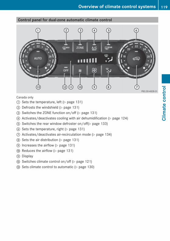
Control panel for dual-zone automatic climate control
Canada only: Sets the temperature, left (Y page 131); Defrosts the windshield (Y page 131)= Switches the ZONE function on/off (Y page 131)? Activates/deactivates cooling with air dehumidification (Y page 124)A Switches the rear window defroster on/off(Y page 133)B Sets the temperature, right (Y page 131)C Activates/deactivates air-recirculation mode (Y page 134)D Sets the air distribution (Y page 131)E Increases the airflow (Y page 131)F Reduces the airflow (Y page 131)G DisplayH Switches climate control on/off (Y page 121)I Sets climate control to automatic (Y page 130)
Overview of climate control systems 119
Climatecontrol
Z
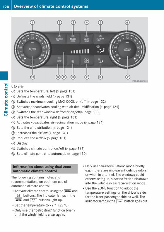
USA only: Sets the temperature, left (Y page 131); Defrosts the windshield (Y page 131)= Switches maximum cooling MAX COOL on/off (Y page 132)? Activates/deactivates cooling with air dehumidification (Y page 124)A Switches the rear window defroster on/off(Y page 133)B Sets the temperature, right (Y page 131)C Activates/deactivates air-recirculation mode (Y page 134)D Sets the air distribution (Y page 131)E Increases the airflow (Y page 131)F Reduces the airflow (Y page 131)G DisplayH Switches climate control on/off (Y page 121)I Sets climate control to automatic (Y page 130)
Information about using dual-zoneautomatic climate controlThe following contains notes andrecommendations on optimum use ofautomatic climate control.RActivate climate control using theà andÁ buttons. The indicator lamps in theà andÁ buttons light up.RSet the temperature to 72 ‡ (22 †).ROnly use the "defrosting" function brieflyuntil the windshield is clear again.
ROnly use "air-recirculation" mode briefly,e.g. if there are unpleasant outside odorsor when in a tunnel. The windows couldotherwise fog up, since no fresh air is drawninto the vehicle in air-recirculation mode.RUse the ZONE function to adopt thetemperature settings on the driver's sidefor the front-passenger side as well. Theindicator lamp in theá button goes out.
120 Overview of climate control systemsClimatecontrol
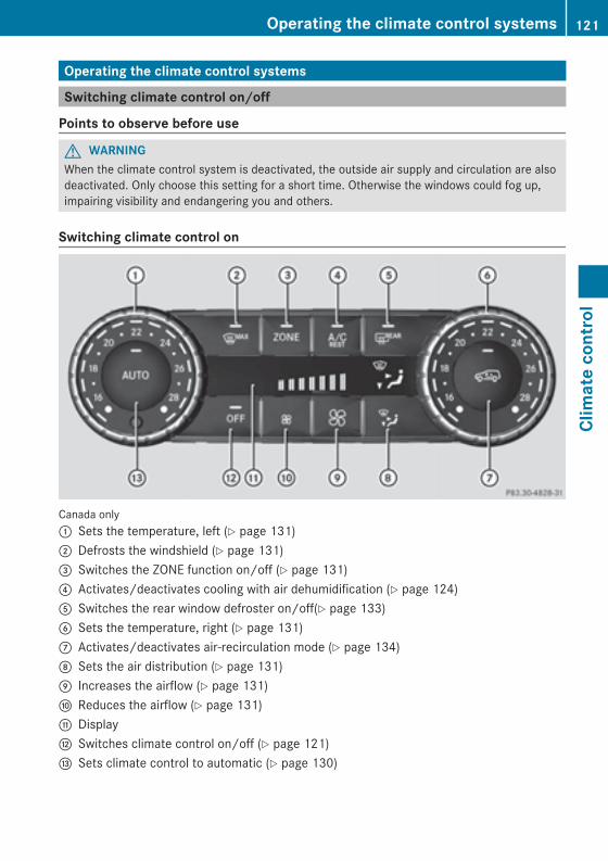
Operating the climate control systems
Switching climate control on/off
Points to observe before use
G WARNINGWhen the climate control system is deactivated, the outside air supply and circulation are alsodeactivated. Only choose this setting for a short time. Otherwise the windows could fog up,impairing visibility and endangering you and others.
Switching climate control on
Canada only: Sets the temperature, left (Y page 131); Defrosts the windshield (Y page 131)= Switches the ZONE function on/off (Y page 131)? Activates/deactivates cooling with air dehumidification (Y page 124)A Switches the rear window defroster on/off(Y page 133)B Sets the temperature, right (Y page 131)C Activates/deactivates air-recirculation mode (Y page 134)D Sets the air distribution (Y page 131)E Increases the airflow (Y page 131)F Reduces the airflow (Y page 131)G DisplayH Switches climate control on/off (Y page 121)I Sets climate control to automatic (Y page 130)
Operating the climate control systems 121
Climatecontrol
Z
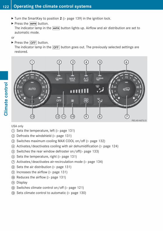
X Turn the SmartKey to position 2 (Y page 139) in the ignition lock.X Press theà button.The indicator lamp in theà button lights up. Airflow and air distribution are set toautomatic mode.
orX Press the^ button.The indicator lamp in the^ button goes out. The previously selected settings arerestored.
USA only: Sets the temperature, left (Y page 131); Defrosts the windshield (Y page 131)= Switches maximum cooling MAX COOL on/off (Y page 132)? Activates/deactivates cooling with air dehumidification (Y page 124)A Switches the rear window defroster on/off(Y page 133)B Sets the temperature, right (Y page 131)C Activates/deactivates air-recirculation mode (Y page 134)D Sets the air distribution (Y page 131)E Increases the airflow (Y page 131)F Reduces the airflow (Y page 131)G DisplayH Switches climate control on/off (Y page 121)I Sets climate control to automatic (Y page 130)
122 Operating the climate control systemsClimatecontrol
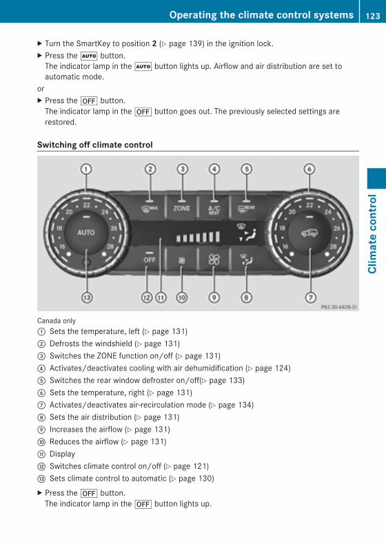
X Turn the SmartKey to position 2 (Y page 139) in the ignition lock.X Press theà button.The indicator lamp in theà button lights up. Airflow and air distribution are set toautomatic mode.
orX Press the^ button.The indicator lamp in the^ button goes out. The previously selected settings arerestored.
Switching off climate control
Canada only: Sets the temperature, left (Y page 131); Defrosts the windshield (Y page 131)= Switches the ZONE function on/off (Y page 131)? Activates/deactivates cooling with air dehumidification (Y page 124)A Switches the rear window defroster on/off(Y page 133)B Sets the temperature, right (Y page 131)C Activates/deactivates air-recirculation mode (Y page 134)D Sets the air distribution (Y page 131)E Increases the airflow (Y page 131)F Reduces the airflow (Y page 131)G DisplayH Switches climate control on/off (Y page 121)I Sets climate control to automatic (Y page 130)X Press the^ button.The indicator lamp in the^ button lights up.
Operating the climate control systems 123
Climatecontrol
Z
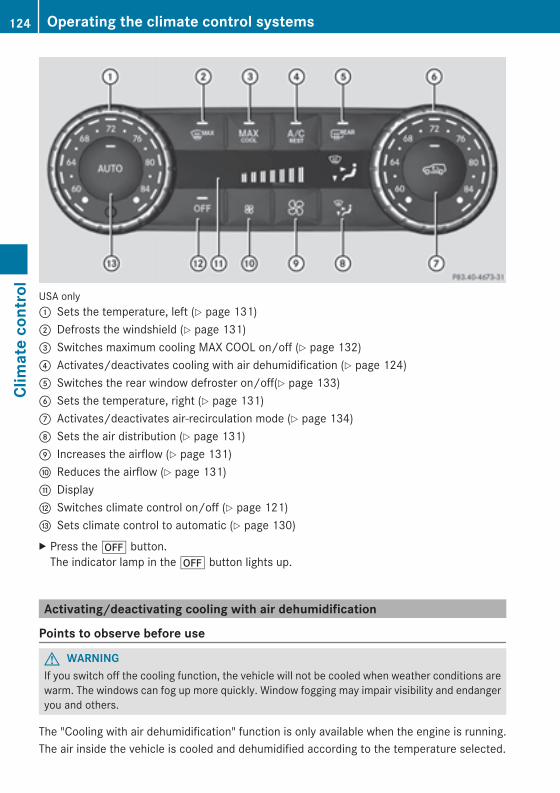
USA only: Sets the temperature, left (Y page 131); Defrosts the windshield (Y page 131)= Switches maximum cooling MAX COOL on/off (Y page 132)? Activates/deactivates cooling with air dehumidification (Y page 124)A Switches the rear window defroster on/off(Y page 133)B Sets the temperature, right (Y page 131)C Activates/deactivates air-recirculation mode (Y page 134)D Sets the air distribution (Y page 131)E Increases the airflow (Y page 131)F Reduces the airflow (Y page 131)G DisplayH Switches climate control on/off (Y page 121)I Sets climate control to automatic (Y page 130)X Press the^ button.The indicator lamp in the^ button lights up.
Activating/deactivating cooling with air dehumidification
Points to observe before use
G WARNINGIf you switch off the cooling function, the vehicle will not be cooled when weather conditions arewarm. The windows can fog up more quickly. Window fogging may impair visibility and endangeryou and others.
The "Cooling with air dehumidification" function is only available when the engine is running.The air inside the vehicle is cooled and dehumidified according to the temperature selected.
124 Operating the climate control systemsClimatecontrol
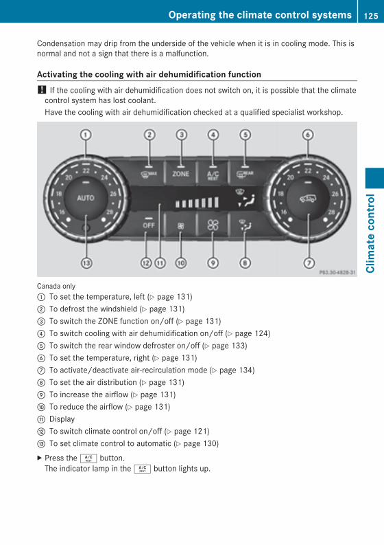
Condensation may drip from the underside of the vehicle when it is in cooling mode. This isnormal and not a sign that there is a malfunction.
Activating the cooling with air dehumidification function! If the cooling with air dehumidification does not switch on, it is possible that the climatecontrol system has lost coolant.Have the cooling with air dehumidification checked at a qualified specialist workshop.
Canada only: To set the temperature, left (Y page 131); To defrost the windshield (Y page 131)= To switch the ZONE function on/off (Y page 131)? To switch cooling with air dehumidification on/off (Y page 124)A To switch the rear window defroster on/off (Y page 133)B To set the temperature, right (Y page 131)C To activate/deactivate air-recirculation mode (Y page 134)D To set the air distribution (Y page 131)E To increase the airflow (Y page 131)F To reduce the airflow (Y page 131)G DisplayH To switch climate control on/off (Y page 121)I To set climate control to automatic (Y page 130)X Press theÁ button.The indicator lamp in theÁ button lights up.
Operating the climate control systems 125
Climatecontrol
Z
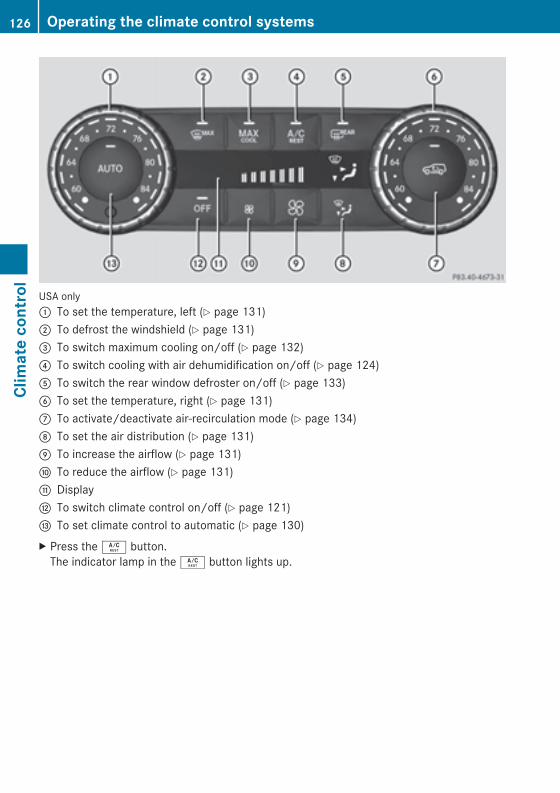
USA only: To set the temperature, left (Y page 131); To defrost the windshield (Y page 131)= To switch maximum cooling on/off (Y page 132)? To switch cooling with air dehumidification on/off (Y page 124)A To switch the rear window defroster on/off (Y page 133)B To set the temperature, right (Y page 131)C To activate/deactivate air-recirculation mode (Y page 134)D To set the air distribution (Y page 131)E To increase the airflow (Y page 131)F To reduce the airflow (Y page 131)G DisplayH To switch climate control on/off (Y page 121)I To set climate control to automatic (Y page 130)X Press theÁ button.The indicator lamp in theÁ button lights up.
126 Operating the climate control systemsClimatecontrol

Switching off the cooling with air dehumidification
Canada only: To set the temperature, left (Y page 131); To defrost the windshield (Y page 131)= To switch the ZONE function on/off (Y page 131)? To switch cooling with air dehumidification on/off (Y page 124)A To switch the rear window defroster on/off (Y page 133)B To set the temperature, right (Y page 131)C To activate/deactivate air-recirculation mode (Y page 134)D To set the air distribution (Y page 131)E To increase the airflow (Y page 131)F To reduce the airflow (Y page 131)G DisplayH To switch climate control on/off (Y page 121)I To set climate control to automatic (Y page 130)X Press theÁ button.The indicator lamp in theÁ button goes out. The "Cooling with air dehumidification"function has a delayed switch-off feature.
Operating the climate control systems 127
Climatecontrol
Z
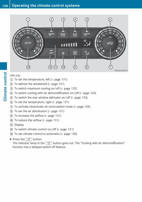
USA only: To set the temperature, left (Y page 131); To defrost the windshield (Y page 131)= To switch maximum cooling on/off (Y page 132)? To switch cooling with air dehumidification on/off (Y page 124)A To switch the rear window defroster on/off (Y page 133)B To set the temperature, right (Y page 131)C To activate/deactivate air-recirculation mode (Y page 134)D To set the air distribution (Y page 131)E To increase the airflow (Y page 131)F To reduce the airflow (Y page 131)G DisplayH To switch climate control on/off (Y page 121)I To set climate control to automatic (Y page 130)X Press theÁ button.The indicator lamp in theÁ button goes out. The "Cooling with air dehumidification"function has a delayed switch-off feature.
128 Operating the climate control systemsClimatecontrol
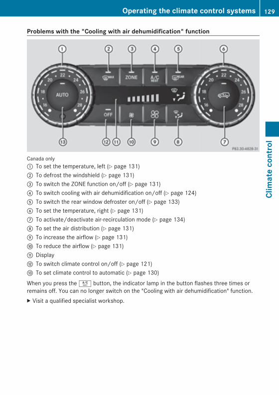
Problems with the "Cooling with air dehumidification" function
Canada only: To set the temperature, left (Y page 131); To defrost the windshield (Y page 131)= To switch the ZONE function on/off (Y page 131)? To switch cooling with air dehumidification on/off (Y page 124)A To switch the rear window defroster on/off (Y page 133)B To set the temperature, right (Y page 131)C To activate/deactivate air-recirculation mode (Y page 134)D To set the air distribution (Y page 131)E To increase the airflow (Y page 131)F To reduce the airflow (Y page 131)G DisplayH To switch climate control on/off (Y page 121)I To set climate control to automatic (Y page 130)
When you press theÁ button, the indicator lamp in the button flashes three times orremains off. You can no longer switch on the "Cooling with air dehumidification" function.X Visit a qualified specialist workshop.
Operating the climate control systems 129
Climatecontrol
Z
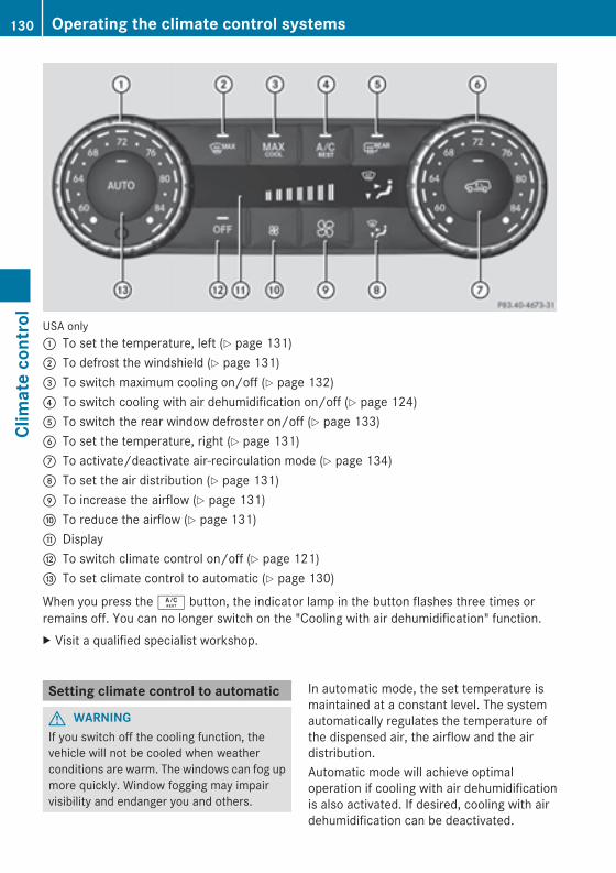
USA only: To set the temperature, left (Y page 131); To defrost the windshield (Y page 131)= To switch maximum cooling on/off (Y page 132)? To switch cooling with air dehumidification on/off (Y page 124)A To switch the rear window defroster on/off (Y page 133)B To set the temperature, right (Y page 131)C To activate/deactivate air-recirculation mode (Y page 134)D To set the air distribution (Y page 131)E To increase the airflow (Y page 131)F To reduce the airflow (Y page 131)G DisplayH To switch climate control on/off (Y page 121)I To set climate control to automatic (Y page 130)
When you press theÁ button, the indicator lamp in the button flashes three times orremains off. You can no longer switch on the "Cooling with air dehumidification" function.X Visit a qualified specialist workshop.
Setting climate control to automatic
G WARNINGIf you switch off the cooling function, thevehicle will not be cooled when weatherconditions are warm. The windows can fog upmore quickly. Window fogging may impairvisibility and endanger you and others.
In automatic mode, the set temperature ismaintained at a constant level. The systemautomatically regulates the temperature ofthe dispensed air, the airflow and the airdistribution.Automatic mode will achieve optimaloperation if cooling with air dehumidificationis also activated. If desired, cooling with airdehumidification can be deactivated.
130 Operating the climate control systemsClimatecontrol
X Turn the SmartKey to position2 (Y page 139) in the ignition lock.
X Set the desired temperature.X To switch on: press theà button.The indicator lamp in theà button lightsup. Automatic air distribution and airfloware activated.
X To deactivate: press the_ button.orX Press theI orK button.The indicator lamp in theà button goesout.
Setting the temperatureYou can set the temperature separately forthe driver's and front-passenger sides withcontrols: orB(Y page 119).X Turn the SmartKey to position2 (Y page 139) in the ignition lock.
X Set control: orB(Y page 119) to thedesired temperature.Only change the temperature setting insmall increments. Start at 72 ‡ (22 †).
Setting the air distributionX Turn the SmartKey to position2 (Y page 139) in the ignition lock.
X Press the_ button repeatedly until thedesired symbol appears in the display.
P Directs the airflow through the centervents
O Directs the airflow through thefootwell air vents
S Directs the airflow through the centerand footwell vents
¯ Directs air through the defroster ventsb Canada only: directs the airflow
through the defroster and center vents
a Directs air through the defroster andfootwell vents
_ Canada only: directs the airflowthrough the defroster, center and sideair vents and the footwell
Setting the airflowX Turn the SmartKey to position2 (Y page 139) in the ignition lock.
X To increase: press theK button.X To reduce: press theI button.
i The airflow from the rear-compartmentvents and the center vents is the same.
Switching the ZONE function on/offX To switch on: press theá button.The indicator lamp in theá button lightsup.i The temperature setting for the driver'sside is not adopted for the front-passengerside and the rear compartment. Thetemperature for the front-passenger sideand the rear compartment must be setseparately.
X To switch off: press buttoná.The indicator lamp in theá button goesout.i The temperature setting for the driver'sside is adopted for the front-passenger sideand the rear compartment.
Defrosting the windshieldYou can use this function to defrost thewindshield or to defrost the inside of thewindshield and the side windows.i You should only select the defrostingfunction until the windshield is clear again.
Operating the climate control systems 131
Climatecontrol
Z
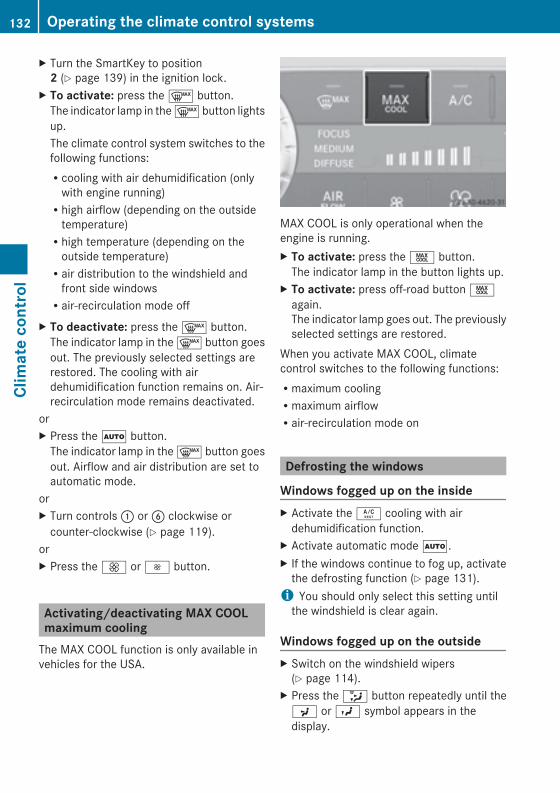
X Turn the SmartKey to position2 (Y page 139) in the ignition lock.
X To activate: press the¬ button.The indicator lamp in the¬ button lightsup.The climate control system switches to thefollowing functions:Rcooling with air dehumidification (onlywith engine running)Rhigh airflow (depending on the outsidetemperature)Rhigh temperature (depending on theoutside temperature)Rair distribution to the windshield andfront side windowsRair-recirculation mode off
X To deactivate: press the¬ button.The indicator lamp in the¬ button goesout. The previously selected settings arerestored. The cooling with airdehumidification function remains on. Air-recirculation mode remains deactivated.
orX Press theà button.The indicator lamp in the¬ button goesout. Airflow and air distribution are set toautomatic mode.
orX Turn controls: orB clockwise orcounter-clockwise (Y page 119).
orX Press theK orI button.
Activating/deactivating MAX COOLmaximum coolingThe MAX COOL function is only available invehicles for the USA.
MAX COOL is only operational when theengine is running.X To activate: press theÙ button.The indicator lamp in the button lights up.
X To activate: press off-road buttonÙagain.The indicator lamp goes out. The previouslyselected settings are restored.
When you activate MAX COOL, climatecontrol switches to the following functions:Rmaximum coolingRmaximum airflowRair-recirculation mode on
Defrosting the windows
Windows fogged up on the insideX Activate theÁ cooling with airdehumidification function.
X Activate automatic modeÃ.X If the windows continue to fog up, activatethe defrosting function (Y page 131).i You should only select this setting untilthe windshield is clear again.
Windows fogged up on the outsideX Switch on the windshield wipers(Y page 114).
X Press the_ button repeatedly until theP orO symbol appears in thedisplay.
132 Operating the climate control systemsClimatecontrol
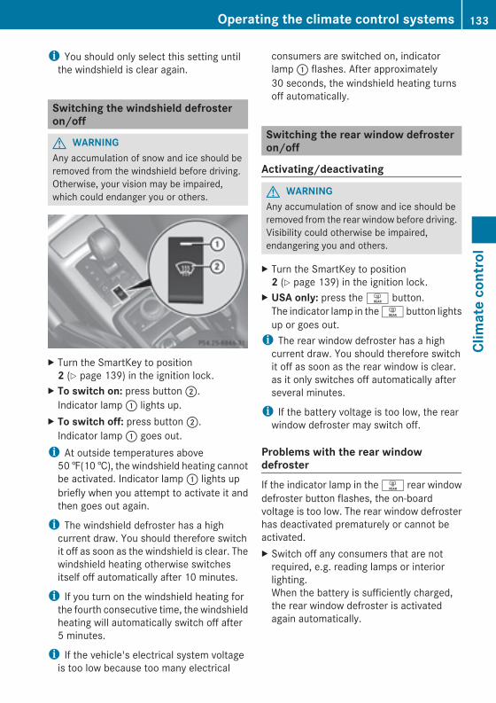
i You should only select this setting untilthe windshield is clear again.
Switching the windshield defrosteron/off
G WARNINGAny accumulation of snow and ice should beremoved from the windshield before driving.Otherwise, your vision may be impaired,which could endanger you or others.
X Turn the SmartKey to position2 (Y page 139) in the ignition lock.
X To switch on: press button;.Indicator lamp: lights up.
X To switch off: press button;.Indicator lamp: goes out.i At outside temperatures above50‡(10†), the windshield heating cannotbe activated. Indicator lamp: lights upbriefly when you attempt to activate it andthen goes out again.
i The windshield defroster has a highcurrent draw. You should therefore switchit off as soon as the windshield is clear. Thewindshield heating otherwise switchesitself off automatically after 10 minutes.
i If you turn on the windshield heating forthe fourth consecutive time, the windshieldheating will automatically switch off after5 minutes.
i If the vehicle's electrical system voltageis too low because too many electrical
consumers are switched on, indicatorlamp: flashes. After approximately30 seconds, the windshield heating turnsoff automatically.
Switching the rear window defrosteron/off
Activating/deactivating
G WARNINGAny accumulation of snow and ice should beremoved from the rear window before driving.Visibility could otherwise be impaired,endangering you and others.
X Turn the SmartKey to position2 (Y page 139) in the ignition lock.
X USA only: press theª button.The indicator lamp in theª button lightsup or goes out.i The rear window defroster has a highcurrent draw. You should therefore switchit off as soon as the rear window is clear.as it only switches off automatically afterseveral minutes.
i If the battery voltage is too low, the rearwindow defroster may switch off.
Problems with the rear windowdefrosterIf the indicator lamp in theª rear windowdefroster button flashes, the on-boardvoltage is too low. The rear window defrosterhas deactivated prematurely or cannot beactivated.X Switch off any consumers that are notrequired, e.g. reading lamps or interiorlighting.When the battery is sufficiently charged,the rear window defroster is activatedagain automatically.
Operating the climate control systems 133
Climatecontrol
Z
Activating/deactivating air-recirculation mode
G WARNINGFogged windows impair visibility,endangering you and others. If the windowsbegin to fog on the inside, switching off theair recirculation mode immediately shouldclear interior window fogging. If interiorwindow fogging persists, make sure the airconditioning is activated, or press the¬button.
X Turn the SmartKey to position2 (Y page 139) in the ignition lock.
X To switch on: press thed button.The indicator lamp in thed button lightsup.i Air-recirculation mode is automaticallyactivated at high levels of pollution or athigh outside temperatures. When air-recirculation mode is activatedautomatically, the indicator lamp in thed button is not lit.Outside air is added after approximately30 minutes.
X To deactivate: press thed button.The indicator lamp in thed button goesout.i Air-recirculation mode switches offautomatically:Rafter approximately five minutes atoutside temperatures belowapproximately 41 ‡Rafter approximately five minutes ifcooling with air dehumidification isdeactivatedRafter approximately 30 minutes atoutside temperatures aboveapproximately 41 ‡ (5 †)
Activating/deactivating the residualheat functionThe "residual heat" function is only availablein Canada.It is possible to make use of the residual heatof the engine to continue heating thestationary vehicle for up to 30 minutes afterthe engine has been switched off. The heatingtimedepends on the coolant temperature andon the interior temperature that has been set.i The blower will run at a low speedregardless of the airflow setting.
i If you activate the residual heat functionat high temperatures, only the ventilationwill be activated.
X Turn the SmartKey to position0(Y page 139) in the ignition lock orremove it.
X To activate: press theÁ button.The indicator lamp in theÁ button lightsup.
X To deactivate: press theÁ button.The indicator lamp in theÁ button goesout.i Residual heat is deactivatedautomatically:Rafter approximately 30 minutesRwhen the ignition is switched onRif the battery voltage dropsRif the coolant temperature is too low
Setting the air vents
Important safety notes
G WARNINGWhen operating the climate control, the airthat enters the passenger compartmentthrough the air vents can be very hot or verycold (depending on the set temperature). Thiscould cause burns or frostbite to unprotectedskin in the immediate area of the air vents.
134 Setting the air ventsClimatecontrol
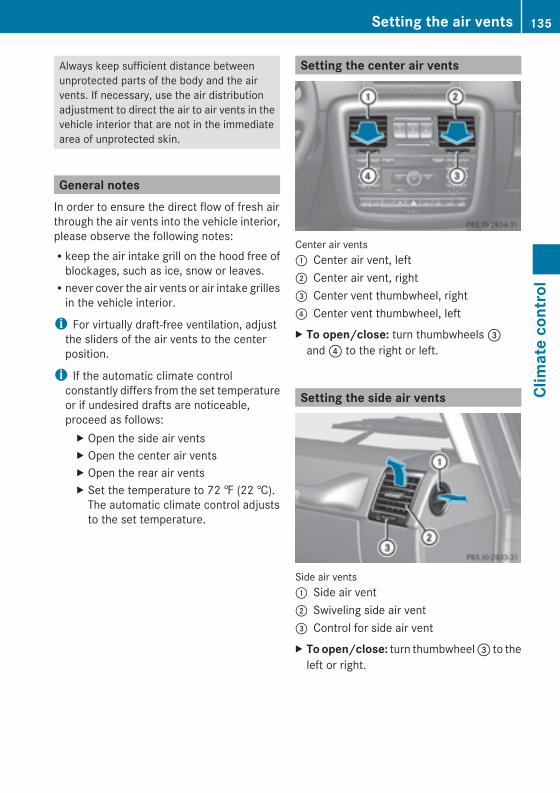
Always keep sufficient distance betweenunprotected parts of the body and the airvents. If necessary, use the air distributionadjustment to direct the air to air vents in thevehicle interior that are not in the immediatearea of unprotected skin.
General notesIn order to ensure the direct flow of fresh airthrough the air vents into the vehicle interior,please observe the following notes:Rkeep the air intake grill on the hood free ofblockages, such as ice, snow or leaves.Rnever cover the air vents or air intake grillesin the vehicle interior.
i For virtually draft-free ventilation, adjustthe sliders of the air vents to the centerposition.
i If the automatic climate controlconstantly differs from the set temperatureor if undesired drafts are noticeable,proceed as follows:X Open the side air ventsX Open the center air ventsX Open the rear air ventsX Set the temperature to 72 ‡ (22 †).The automatic climate control adjuststo the set temperature.
Setting the center air vents
Center air vents: Center air vent, left; Center air vent, right= Center vent thumbwheel, right? Center vent thumbwheel, leftX To open/close: turn thumbwheels=and? to the right or left.
Setting the side air vents
Side air vents: Side air vent; Swiveling side air vent= Control for side air ventX Toopen/close: turn thumbwheel= to theleft or right.
Setting the air vents 135
Climatecontrol
Z
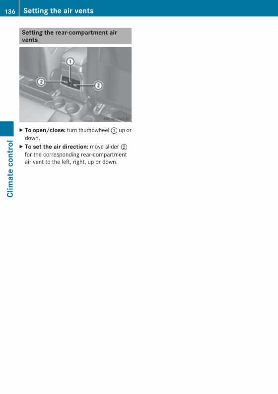
Setting the rear-compartment airvents
X To open/close: turn thumbwheel: up ordown.
X To set the air direction: move slider;for the corresponding rear-compartmentair vent to the left, right, up or down.
136 Setting the air ventsClimatecontrol
Useful information ............................ 138Notes on breaking-in a new vehicle 138Driving ............................................... 138Automatic transmission ................... 145Refueling ............................................ 153Parking ............................................... 156Driving tips ........................................ 158Driving systems ................................ 168Off-road driving systems .................. 193Towing a trailer ................................. 198
137
Drivingandparking
Useful information
i This Operator's Manual describes allmodels and all standard and optionalequipment of your vehicle available at thetime of publication of the Operator'sManual. Country-specific differences arepossible. Please note that your vehicle maynot be equipped with all featuresdescribed. This also applies to safety-related systems and functions.
i Read the information on qualifiedspecialist workshops: (Y page 24).
Notes on breaking-in a new vehicle
Important safety notesNew and replaced brake pads and discs onlyreach their optimum braking effect afterseveral hundred kilometers of driving.Compensate for this by applying greater forceto the brake pedal.
The first 1000 miles (1500 km)The more you look after the engine when it isnew, the more satisfied you will be with itsperformance in the future.RYou should therefore drive at varyingvehicle and engine speeds for the first1,000 miles (1,500 km).RAvoid heavy loads, e.g. driving at fullthrottle, during this period.RChange gear in good time, before thetachometer needle isÔ of the way to thered area of the tachometer.RDo not manually shift to a lower gear tobrake the vehicle.RIf possible, do not depress the acceleratorpedal past the point of resistance(kickdown).ROnly select shift ranges 3, 2 or 1 whendriving slowly, e.g. in mountainous terrain.
After 1,000 miles (1,500 km), you canincrease the engine speed gradually and bringthe vehicle to full speed.Additional breaking-in notes for AMGvehicles:RDo not drive faster than 85 mph(140 km/h) for the first 1,000 miles(1,500 km).ROnly allow the engine to reach a maximumengine speed of 4,500 rpm briefly.RChange gear in good time.RAvoid driving off-road before thedifferential oil change at 2,000 miles(3,000 km).RIdeally, for the first 1,000miles (1,500 km),drive in program C.i You should also observe these breaking-in notes if the engine or parts of the drivetrain on your vehicle have been replaced.
i Always observe the respective speedlimits.
AMG vehicles with rear axle lockingdifferentialChange the oil after a breaking-in period of2,000miles (3,000 km) to improve protectionof the differential. This oil change willlengthen the service life of the differential.Have the oil change carried out at a qualifiedspecialist workshop. Mercedes-Benzrecommends that you use an authorizedMercedes-Benz Center for this purpose.
Driving
Important safety notes
G WARNINGObjects in the driver's footwell can restrict thepedal travel or obstruct a depressed pedal.The operating and road safety of the vehicleis jeopardized. There is a risk of an accident.
138 DrivingDrivingandparking
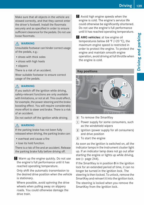
Make sure that all objects in the vehicle arestowed correctly, and that they cannot enterthe driver's footwell. Install the floormatssecurely and as specified in order to ensuresufficient clearance for the pedals. Do not useloose floormats.
G WARNINGUnsuitable footwear can hinder correct usageof the pedals, e.g.:Rshoes with thick solesRshoes with high heelsRslippersThere is a risk of an accident.Wear suitable footwear to ensure correctusage of the pedals.
G WARNINGIf you switch off the ignition while driving,safety-relevant functions are only availablewith limitations, or not at all. This could affect,for example, the power steering and the brakeboosting effect. You will require considerablymore effort to steer and brake. There is a riskof an accident.Do not switch off the ignition while driving.
G WARNINGIf the parking brake has not been fullyreleased when driving, the parking brake can:Roverheat and cause a fireRlose its hold function.There is a risk of fire and an accident. Releasethe parking brake fully before driving off.
! Warm up the engine quickly. Do not usethe engine's full performance until it hasreached operating temperature.Only shift the automatic transmission tothe desired drive position when the vehicleis stationary.Where possible, avoid spinning the drivewheels when pulling away on slipperyroads. You could otherwise damage thedrive train.
! Avoid high engine speeds when theengine is cold. The engine's service lifecould otherwise be significantly shortened.Do not use the engine's full performanceuntil it has reached operating temperature.
! AMG vehicles: at low engine oiltemperatures below 68 ‡ (+20 †), themaximum engine speed is restricted inorder to protect the engine. To protect theengine and maintain smooth engineoperation, avoid driving at full throttle whenthe engine is cold.
Key positions
g To remove the SmartKey1 Power supply for some consumers, such
as the windshield wipers2 Ignition (power supply for all consumers)
and drive position3 To start the engine
As soon as the ignition is switched on, all theindicator lamps in the instrument cluster lightup. If an indicator lamp does not go out afterstarting the engine or lights up while driving,see (Y page 244).If the SmartKey is in position 0 in the ignitionlock for an extended period of time, it can nolonger be turned in the ignition lock. Thesteering is then locked. To unlock, remove theSmartKey and reinsert it into the ignition lock.The steering is locked when you remove theSmartKey from the ignition lock.
Driving 139
Drivingandparking
Z
X Remove the SmartKey when the engine isswitched off.The starter battery could otherwise bedischarged.
If you cannot turn the SmartKey in the ignitionlock, the starter battery may not be chargedsufficiently.X Check the starter battery and charge it ifnecessary (Y page 301).
orX Jump-start the vehicle (Y page 303).
i You can only remove the SmartKey if:Rthe SmartKey is in position 0 in theignition lock.Rthe automatic transmission selectorlever is in P.
Starting the engine
Important safety notes
G WARNINGCombustion engines emit poisonous exhaustgases such as carbon monoxide. Inhalingthese exhaust gases leads to poisoning. Thereis a risk of fatal injury. Therefore never leavethe engine running in enclosed spaceswithout sufficient ventilation.
G WARNINGInhalation of exhaust gas is hazardous to yourhealth. All exhaust gas contains carbonmonoxide (CO), and inhaling it can causeunconsciousness and possible death.Do not run the engine in confined areas (suchas a garage) which are not properly ventilated.If you think that exhaust gas fumes areentering the vehicle while driving, have thecause determined and correctedimmediately. If you must drive under theseconditions, drive only with at least onewindow fully open at all times.
! Do not depress the accelerator pedalwhen starting the engine.
Starting procedureX Shift the automatic transmission toposition P.The transmission position display in themultifunction display shows P.i For further information about theautomatic transmission, see(Y page 145).
i If you depress the brakewhen starting theengine, pedal travel is unusually long andthere is less pedal resistance.
X Make sure that the parking brake isapplied.
X Turn the SmartKey to position 3 in theignition lock (Y page 139) and release it assoon as the engine is running.
i You can also use the touch-start function.To do this, turn the SmartKey to position 3(Y page 139) and release it immediately.The engine then starts automatically.
Pulling away
Automatic transmission
G WARNINGIf the engine speed is above the idling speedand you engage transmission position D orR, the vehicle could pull away suddenly. Thereis a risk of an accident.When engaging transmission position D or R,always firmly depress the brake pedal and donot simultaneously accelerate.
! Only shift the automatic transmission toreverse gear R or park position P when thevehicle is stationary. Otherwise, theautomatic transmission could be damaged.
! Do not depress the accelerator pedalwhile depressing the brake pedal. Thisimpairs engine performance and results inpremature wear on the brake system anddrivetrain.
140 DrivingDrivingandparking
! If a warning tone sounds and theRelease Park. BrakeRelease Park. Brake message appearsin the multifunction display, the parkingbrake is still applied. Release the parkingbrake.
X Depress the brake pedal and keep itdepressed.
X Shift the automatic transmission toposition D or R.i Before driving off, wait until the gearchange is fully completed.
X Release the parking brake (Y page 157).X Release the brake pedal.X Carefully depress the accelerator pedal.
i It is only possible to shift the automatictransmission from position P to a differentposition if you depress the brake pedal.Only then is the selector lever lockreleased.
i The vehicle locks centrally once you havepulled away. The locking knobs in the doorsdrop down.You can open the doors from the inside atany time.You can also deactivate the automaticlocking feature (Y page 216).
i Upshifts take place at higher enginespeeds after a cold start. This helps thecatalytic converter to reach its operatingtemperature more quickly.
Hill start assist
G WARNINGAfter a short time, hill start assist will nolonger brake your vehicle and it could rollaway. There is a risk of an accident and injury.Therefore, quickly move your foot from thebrake pedal to the accelerator pedal. Neverleave the vehicle when it is held by hill startassist.
Hill start assist helps you when pulling awayforwards or in reverse on an uphill gradient.
It holds the vehicle for a short time after youhave removed your foot from the brake pedal.This gives you enough time to move your footfrom the brake pedal to the accelerator pedaland to depress it before the vehicle begins toroll.X Take your foot off the brake pedal.i Once you have taken your foot off thebrake pedal, the vehicle is held for aroundone second.
X Pull away.Hill start assist will not function if:Ryou are pulling away on a level road or ona downhill gradient.Rthe transmission is in position N.Rthe parking brake is applied.RESP® is malfunctioning.
ECO start/stop function (AMGvehicles)
Important safety notes
G WARNINGIf the engine is switched off automatically andyou exit the vehicle, the engine is restartedautomatically. The vehicle may begin moving.There is a risk of accident and injury.If you wish to exit the vehicle, always turn offthe ignition and secure the vehicle againstrolling away.
General notesThe ECO start/stop function is only availablefor the G 63 AMG.The ECO start/stop function switches theengine off automatically when the vehiclestops moving.The engine starts automatically when thedriver wants to pull away again. The ECOstart/stop function thereby helps you toreduce the fuel consumption and emissionsof your vehicle.
Driving 141
Drivingandparking
Z
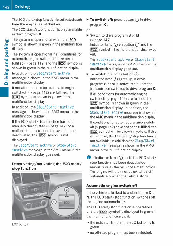
The ECO start/stop function is activated eachtime the engine is switched on.The ECO start/stop function is only availablein drive program C.The system is operational when the¤symbol is shown in green in the multifunctiondisplay.The system is operational if all conditions forautomatic engine switch-off have beenfulfilled (Y page 142) and the¤ symbol isshown in green in the multifunction display.In addition, the Stop/Start activeStop/Start activemessage is shown in the AMG menu in themultifunction display.If not all conditions for automatic engineswitch-off (Y page 142) are fulfilled, the¤ symbol is shown in yellow in themultifunction display.In addition, the Stop/Start inactiveStop/Start inactivemessage is shown in the AMG menu in themultifunction display.If the ECO start/stop function has beenmanually deactivated (Y page 142) or amalfunction has caused the system to bedeactivated, the¤ symbol is notdisplayed.The Stop/Start activeStop/Start active or Stop/StartStop/Startinactiveinactive message in the AMG menu in themultifunction display goes out.
Deactivating/activating the ECO start/stop function
ECO button
X To switch off: press button: in driveprogram C.
orX Switch to drive program S or M(Y page 149).Indicator lamp; on button: and the¤ symbol in themultifunction display goout.The Stop/Start activeStop/Start active or Stop/StartStop/Startinactiveinactivemessage in the AMGmenu in themultifunction display goes out.
X To switch on: press button:.Indicator lamp; lights up. If driveprogram S or M is active, the automatictransmission switches to drive program C.If all conditions for automatic engineswitch-off (Y page 142) are fulfilled, the¤ symbol is shown in green in themultifunction display. In addition, theStop/Start activeStop/Start activemessage is shown inthe AMGmenu in themultifunction display.If conditions for automatic engine switch-off (Y page 142) have not been fulfilled, the¤ symbol will be shown in yellow. If thisis the case, the ECO start/stop function isnot available. In addition, the Stop/StartStop/Startinactiveinactive message is shown in the AMGmenu in the multifunction display.
i If indicator lamp; is off, the ECO start/stop function has been deactivatedmanually or as the result of a malfunction.The engine will then not be switched offautomatically when the vehicle stops.
Automatic engine switch-offIf the vehicle is braked to a standstill in D orN, the ECO start/stop function switches offthe engine automatically.The ECO start/stop function is operationaland the¤ symbol is displayed in green inthe multifunction display, if:Rthe indicator lamp in the ECO button is litgreen.Rno off-road program has been selected.
142 DrivingDrivingandparking
Rthe vehicle is stationary.Rthe outside temperature is within thecomfort range.Rthe engine is at normal operatingtemperature.Rthe set temperature for the vehicle interiorhas been reached.Rthe battery is sufficiently charged.Rthe system detects that the windshield isnot fogged up when the air-conditioningsystem is switched on.Rthe hood is closed.Rthe driver's door is closed and the driver'sseat belt is fastened.
If conditions for automatic engine switch-offhave not been fulfilled, the¤ symbol willbe shown in yellow.In addition, the Stop/Start inactiveStop/Start inactivemessage is shown in the AMG menu in themultifunction display.
i If you shift the transmission from R to D,the ECO start/stop function is availableagain once the¤ symbol reappears ingreen in the multifunction display.
i The engine can be automatically switchedoff an unlimited number of times.
i You can still activate the HOLD functionwhen the vehicle is stationary, even if theengine has been switched offautomatically. It is then not necessary tocontinue applying the brakes during theautomatic stop phase. When you depressthe accelerator pedal, the engine startsautomatically and the braking effect of theHOLD function is deactivated. Depress theaccelerator pedal carefully, as the enginemust be started first.
i During automatic engine switch-off, theclimate control system only operates at areduced capacity. If you require full climatecontrol capacity, the ECO start/stopfunction can be deactivated by pressing theECO button (Y page 142).
Automatic engine startThe engine starts automatically if:RIn general:
- you switch off the ECO start/stopfunction by pressing the ECO button.
- you release the brakes when intransmission position D or N and whenthe HOLD function is not active.
RBy the driver:- you release the brakes when intransmission position D or N.
- you depress the accelerator pedal.- you engage reverse gear R.- you move the transmission out ofposition P.
- you switch to drive program S or M.- you unfasten your seat belt or open thedriver's door.
RBy the system:- the vehicle starts to roll.- the brake system requires this.- the temperature in the vehicle interiordeviates from the set range.
- the system detects moisture on thewindshield when the air-conditioningsystem is switched on.
- the charge level of the battery is too low.
i Shifting the transmission to position Pdoes not start the engine.
Driving 143
Drivingandparking
Z
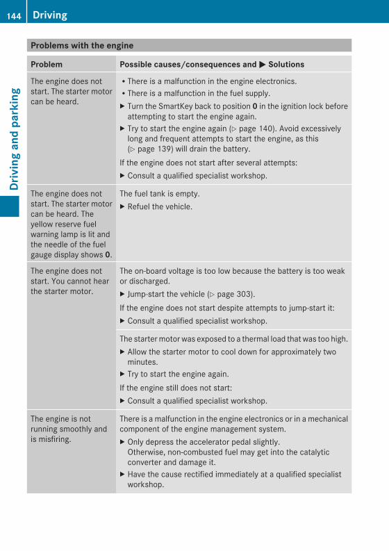
Problems with the engine
Problem Possible causes/consequences andMM Solutions
The engine does notstart. The starter motorcan be heard.
RThere is a malfunction in the engine electronics.RThere is a malfunction in the fuel supply.X Turn the SmartKey back to position 0 in the ignition lock beforeattempting to start the engine again.
X Try to start the engine again (Y page 140). Avoid excessivelylong and frequent attempts to start the engine, as this(Y page 139) will drain the battery.
If the engine does not start after several attempts:X Consult a qualified specialist workshop.
The engine does notstart. The starter motorcan be heard. Theyellow reserve fuelwarning lamp is lit andthe needle of the fuelgauge display shows 0.
The fuel tank is empty.X Refuel the vehicle.
The engine does notstart. You cannot hearthe starter motor.
The on-board voltage is too low because the battery is too weakor discharged.X Jump-start the vehicle (Y page 303).If the engine does not start despite attempts to jump-start it:X Consult a qualified specialist workshop.
The startermotor was exposed to a thermal load that was too high.X Allow the starter motor to cool down for approximately twominutes.
X Try to start the engine again.If the engine still does not start:X Consult a qualified specialist workshop.
The engine is notrunning smoothly andis misfiring.
There is a malfunction in the engine electronics or in a mechanicalcomponent of the engine management system.X Only depress the accelerator pedal slightly.Otherwise, non-combusted fuel may get into the catalyticconverter and damage it.
X Have the cause rectified immediately at a qualified specialistworkshop.
144 DrivingDrivingandparking
Problem Possible causes/consequences and MM Solutions
The coolanttemperature gaugeshows a value above248 ‡(120 †). Adisplay message mayalso appear in themultifunction displayand awarning tonemaysound.
The coolant level is too low. The coolant is too hot and the engineis no longer being cooled sufficiently.X Stop as soon as possible and allow the engine and the coolantto cool down.
X Check the coolant level (Y page 285). Observe the warningnotes as you do so and add coolant if necessary.
If the coolant level is correct, the radiator fan may be faulty. Thecoolant is too hot and the engine is no longer being cooledsufficiently.X At coolant temperatures below 248 ‡ (120 †), drive to thenearest qualified specialist workshop.
X Avoid heavy loads on the engine as you do so, e.g. driving inmountainous terrain and start/stop traffic.
Automatic transmission
Important safety notes
G WARNINGIf the engine speed is above the idling speedand you engage transmission position D orR, the vehicle could pull away suddenly. Thereis a risk of an accident.When engaging transmission position D or R,always firmly depress the brake pedal and donot simultaneously accelerate.
G WARNINGThe automatic transmission switches toneutral position N when you switch off theengine. The vehicle may roll away. There is arisk of an accident.After switching off the engine, always switchto parking position P. Prevent the parkedvehicle from rolling away by applying theparking brake.
i Bear in mind that the power transmissionbetween the engine and the transmissionis interrupted when the engine is switchedoff. For this reason, shift the automatictransmission to P when the engine isswitched off and the vehicle is at a
standstill. Apply the parking brake toprevent the vehicle from rolling away.
Selector lever
Overview of transmission positions! If the engine speed is too high or if thevehicle is rolling, do not shift thetransmission directly from D to R, from Rto D or directly to P.Do not open the driver's door while thevehicle is in motion. At low speeds intransmission position D or R, park positionP is otherwise engaged automatically.The transmission could be damaged.
Automatic transmission 145
Drivingandparking
Z
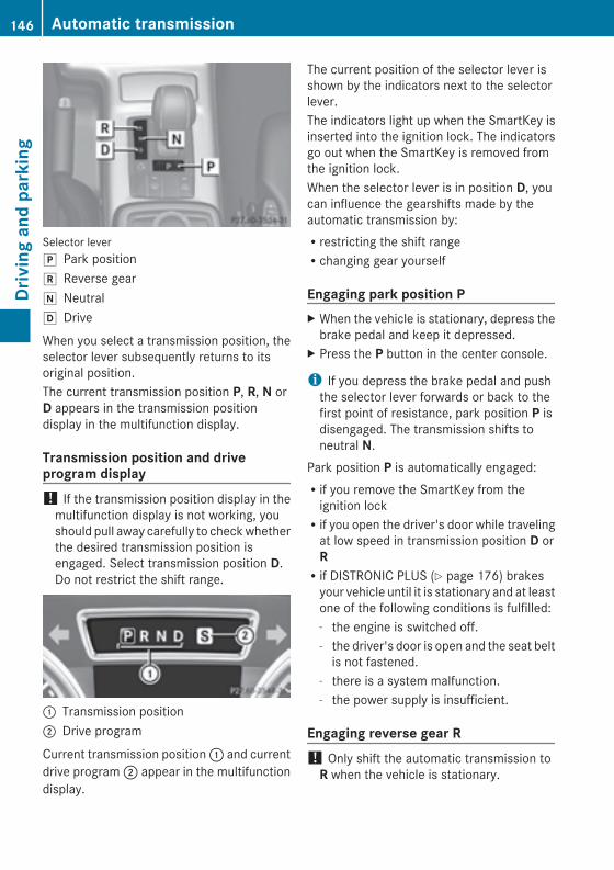
Selector leverj Park positionk Reverse geari Neutralh Drive
When you select a transmission position, theselector lever subsequently returns to itsoriginal position.The current transmission position P, R, N orD appears in the transmission positiondisplay in the multifunction display.
Transmission position and driveprogram display! If the transmission position display in themultifunction display is not working, youshould pull away carefully to checkwhetherthe desired transmission position isengaged. Select transmission position D.Do not restrict the shift range.
: Transmission position; Drive program
Current transmission position: and currentdrive program; appear in the multifunctiondisplay.
The current position of the selector lever isshown by the indicators next to the selectorlever.The indicators light up when the SmartKey isinserted into the ignition lock. The indicatorsgo out when the SmartKey is removed fromthe ignition lock.When the selector lever is in position D, youcan influence the gearshifts made by theautomatic transmission by:Rrestricting the shift rangeRchanging gear yourself
Engaging park position PX When the vehicle is stationary, depress thebrake pedal and keep it depressed.
X Press the P button in the center console.
i If you depress the brake pedal and pushthe selector lever forwards or back to thefirst point of resistance, park position P isdisengaged. The transmission shifts toneutral N.
Park position P is automatically engaged:Rif you remove the SmartKey from theignition lockRif you open the driver's door while travelingat low speed in transmission position D orRRif DISTRONIC PLUS (Y page 176) brakesyour vehicle until it is stationary and at leastone of the following conditions is fulfilled:- the engine is switched off.- the driver's door is open and the seat beltis not fastened.
- there is a system malfunction.- the power supply is insufficient.
Engaging reverse gear R! Only shift the automatic transmission toR when the vehicle is stationary.
146 Automatic transmissionDrivingandparking
X When the vehicle is stationary, depress thebrake pedal and keep it depressed.
X Push the selector lever forwards past thefirst point of resistance.Transmission position R is engaged.
i For AMG vehicles: when reverse gear isengaged and the ECO start/stop functionis switched on, the engine starts upautomatically (Y page 141).
Shifting to neutral N
G WARNINGWhen leaving the SmartKey in the starterswitch, do not leave children unattended inthe vehicle. It is possible for children to switchon the ignition which could result inunsupervised use of vehicle equipment.Unsupervised use of vehicle equipment couldresult in an accident and/or serious personalinjury.
If the vehicle is stationary:X Depress the brake pedal.X Depending on the current transmissionposition, press the selector lever forwardsor backwards to the first point ofresistance.The automatic transmission shifts to N.
If the engine has been switched off, theautomatic transmission automatically shiftsto N.i For AMG vehicles: the ECO start/stopfunction switches the engine offautomatically if the vehicle is braked to astandstill when in neutral N and the brakeis still depressed (Y page 141).
Remaining in neutral N
G WARNINGIf children are left unsupervised in the vehicle,they could:Ropen the doors, thus endangering otherpeople or road users.Rget out and disrupt traffic.Roperate the vehicle's equipment.Additionally, children could set the vehicle inmotion if, for example, they:Rrelease the parking brake.Rshift the automatic transmission out ofparking position P.Rstarting the engine.There is a risk of an accident and injury.When leaving the vehicle, always take theSmartKeywith you and lock the vehicle. Neverleave children or animals unattended in thevehicle. Always keep the SmartKey out ofreach of children.
X Make sure that the ignition is switched on.X When the vehicle is stationary, depress thebrake pedal and keep it depressed.
X Shift to neutral N.X Release the brake pedal.X If the parking brake is applied, release it.X Switch off the ignition and leave theSmartKey in the ignition lock.
Shifting to transmission position DX When the vehicle is stationary, depress thebrake pedal and keep it depressed.
X Push the selector lever back past the firstpoint of resistance.Transmission position D is engaged.
i For AMG vehicles: the ECO start/stopfunction switches the engine offautomatically if the vehicle is braked to astandstill when in transmission position Dand the brake is still depressed(Y page 141).
Automatic transmission 147
Drivingandparking
Z
Transmission positions
B Park positionDo not shift the transmission intoposition P (Y page 145) unless thevehicle is stationary. The parkinglock should not be used as a brakewhen parking. In addition toengaging the parking lock, youmust always apply the parkingbrake to secure the vehicle.
i The SmartKey can only beremoved if the transmission is inposition P. When there is noSmartKey in the ignition lock, theselector lever is locked inposition P.
Have the vehicle electronicschecked immediately at a qualifiedspecialist workshop.
C Reverse gearOnly shift the transmission to Rwhen the vehicle is stationary.
A NeutralNo power is transmitted from theengine to the drive wheels.Releasing the brakes will allow youto move the vehicle freely, e.g. topush it or tow it.Do not shift the transmission to Nwhile driving. Otherwise, theautomatic transmission could bedamaged.If ESP® is deactivated or faulty:only shift the transmission topositionN if the vehicle is in dangerof skidding, e.g. on icy roads.If you want to engage the transfercase, shift briefly into N(Y page 194).
! Rolling in neutralN can damagethe drive train.
7 DriveThe automatic transmissionchanges gear automatically. Allforward gears are available.
Changing gearThe automatic transmission shifts to theindividual gears automatically when it is intransmission position D. This automaticgearshifting behavior is determined by:Ra shift range restriction, if selectedRthe position of the transfer case (HIGHRANGE or LOW RANGE)Rthe position of the accelerator pedalRthe road speed
148 Automatic transmissionDrivingandparking
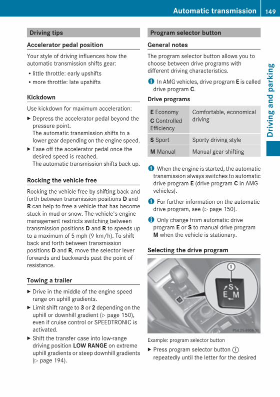
Driving tips
Accelerator pedal positionYour style of driving influences how theautomatic transmission shifts gear:Rlittle throttle: early upshiftsRmore throttle: late upshifts
KickdownUse kickdown for maximum acceleration:X Depress the accelerator pedal beyond thepressure point.The automatic transmission shifts to alower gear depending on the engine speed.
X Ease off the accelerator pedal once thedesired speed is reached.The automatic transmission shifts back up.
Rocking the vehicle freeRocking the vehicle free by shifting back andforth between transmission positions D andR can help to free a vehicle that has becomestuck in mud or snow. The vehicle's enginemanagement restricts switching betweentransmission positions D and R to speeds upto a maximum of 5 mph (9 km/h). To shiftback and forth between transmissionpositions D and R, move the selector leverforwards and backwards past the point ofresistance.
Towing a trailerX Drive in the middle of the engine speedrange on uphill gradients.
X Limit shift range to 3 or 2 depending on theuphill or downhill gradient (Y page 150),even if cruise control or SPEEDTRONIC isactivated.
X Shift the transfer case into low-rangedriving position LOW RANGE on extremeuphill gradients or steep downhill gradients(Y page 194).
Program selector button
General notesThe program selector button allows you tochoose between drive programs withdifferent driving characteristics.
i In AMG vehicles, drive program E is calleddrive program C.
Drive programs
E EconomyC ControlledEfficiency
Comfortable, economicaldriving
S Sport Sporty driving style
M Manual Manual gear shifting
i When the engine is started, the automatictransmission always switches to automaticdrive program E (drive program C in AMGvehicles).
i For further information on the automaticdrive program, see (Y page 150).
i Only change from automatic driveprogram E or S to manual drive programM when the vehicle is stationary.
Selecting the drive program
Example: program selector buttonX Press program selector button:repeatedly until the letter for the desired
Automatic transmission 149
Drivingandparking
Z
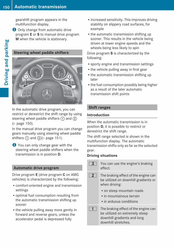
gearshift program appears in themultifunction display.i Only change from automatic driveprogram E or S to manual drive programM when the vehicle is stationary.
Steering wheel paddle shifters
In the automatic drive program, you canrestrict or derestrict the shift range by usingsteering wheel paddle shifters: and;(Y page 150).In the manual drive program you can changegears manually using steering wheel paddleshifters: and;(Y page 151).
i You can only change gear with thesteering wheel paddle shifters when thetransmission is in position D.
Automatic drive programDrive program E (drive program C on AMGvehicles) is characterized by the following:Rcomfort-oriented engine and transmissionsettingsRoptimal fuel consumption resulting fromthe automatic transmission shifting upsoonerRthe vehicle pulling away more gently inforward and reverse gears, unless theaccelerator pedal is depressed fully
Rincreased sensitivity. This improves drivingstability on slippery road surfaces, forexampleRthe automatic transmission shifting upsooner. This results in the vehicle beingdriven at lower engine speeds and thewheels being less likely to spin
Drive program S is characterized by thefollowing:Rsporty engine and transmission settingsRthe vehicle pulling away in first gearRthe automatic transmission shifting uplaterRthe fuel consumption possibly being higheras a result of the later automatictransmission shift points
Shift ranges
IntroductionWhen the automatic transmission is inposition D, it is possible to restrict orderestrict the shift range.The shift range selected is shown in themultifunction display. The automatictransmission shifts only as far as the selectedgear.Driving situations
= You can use the engine's brakingeffect.
5 The braking effect of the engine canbe utilized on downhill gradients orwhen driving:Ron steep mountain roadsRin mountainous terrainRin arduous conditions
4 The braking effect of the engine canbe utilized on extremely steepdownhill gradients and longdownhill stretches.
150 Automatic transmissionDrivingandparking
Restricting the shift rangeX Pull the left-hand steering wheel paddleshifter (Y page 150).The automatic transmission shifts downone gear and restricts the shift range to therelevant gear.
i If the engine exceeds the maximumengine speed when shifting down, theautomatic transmission protects againstengine damage by not shifting down.
i If the maximum engine speed for the shiftrange is reached and you continue toaccelerate, the automatic transmissionshifts up in order to prevent the enginefrom overrevving, even if the shift range isrestricted.
Derestricting the shift rangeX Pull the right-hand steering wheel paddleshifter (Y page 150).The automatic transmission shifts up onegear and restricts the shift range to therelevant gear.
Clearing the shift range restrictionX Pull and hold the right-hand steering wheelpaddle shifter (Y page 150) untilD is shownagain in the multifunction display.The automatic transmission shifts from thecurrent shift range directly to D.
Selecting the ideal shift rangeX Pull the left-hand steering wheel paddleshifter (Y page 150) and hold it in position.The automatic transmission shifts to thegear which allows optimum accelerationand deceleration. To do this, the automatictransmission shifts down one or moregears.
i The automatic transmission cannot shiftdown beyond second gear. To shift to firstgear, you have to pull the left steeringwheel paddle shifter.
Manual drive program
IntroductionIn drive program M, you can change gearmanually using the steering wheel paddleshifters. For this, the transmission must be inposition D. The gear currently selected andengaged is shown in the multifunctiondisplay.Manual drive program M differs from driveprograms E and S with regard to spontaneity,responsiveness and smoothness of gearchanges.
Switching on the manual drive programX Press the program selector button(Y page 149) repeatedly untilM appears inthe multifunction display.
Upshifting (except AMG vehicles)X Pull the right-hand paddle (Y page 150).The automatic transmission shifts up to thenext gear.
Shifting up (AMG vehicles)! Inmanual drive programM, the automatictransmission does not shift upautomatically even when the enginelimiting speed for the current gear isreached. When the engine limiting speed isreached, the fuel supply is cut to preventthe engine from overrevving. Always makesure that the engine speed does not reachthe red area of the tachometer. There isotherwise a risk of engine damage.
X Pull the right-hand paddle (Y page 150).The automatic transmission shifts up to thenext gear.
Before the engine speed reaches the red area,an upshift indicator will be shown in themultifunction display.X If the color in the speedometermultifunction display changes to red and
Automatic transmission 151
Drivingandparking
Z
the UPUP display message is shown, shift upa gear.
DownshiftingX Pull the left-hand paddle (Y page 150).The automatic transmission shifts down tothe next gear.
i If you slow down or stop without shiftingdown, the automatic transmissionautomatically shifts down.
Selecting the optimal gear formaximum accelerationX Pull the left-hand steering wheel paddleshifter until the transmission selects theoptimum gear for the current speed.
KickdownYou can also use kickdown for maximumacceleration in manual drive program M.X Depress the accelerator pedal beyond thepressure point.The transmission shifts to a lower geardepending on the engine speed.
X Shift back up once the desired speed isreached.
i Vehicles with an AMG engine: it is notpossible to use kickdown in manual driveprogram M.i Vehicles without an AMG engine: if youapply full throttle, the automatictransmission shifts up to the next gearwhen the maximum engine speed isreached. This prevents the engine fromoverrevving.
Switching off themanual drive programX Press the program selector button(Y page 149) repeatedly until E (C in AMGvehicles) or S appears in the multifunctiondisplay.
152 Automatic transmissionDrivingandparking
Problems with the automatic transmission
Problem Possible causes/consequences andMM Solutions
The acceleration abilityis deteriorating.The transmission nolonger changes gear.
The transmission is in emergency mode.It is only possible to shift into second gear and reverse gear.X Stop the vehicle.X Shift the transmission to position P.X Turn the SmartKey to position 0 in the ignition lock.X Wait at least ten seconds before restarting the engine.X Shift the transmission to position D or R.If D is selected, the transmission shifts into second gear; if R isselected, the transmission shifts into reverse gear.
X Have the transmission checked at a qualified specialistworkshop immediately.
You hear a warningtone.
You have:Rswitched off the engineRopened the driver's doorRnot moved the selector lever to position PX Move the selector lever to position P.
Refueling
Important safety notes
G WARNINGGasoline is highly flammable and poisonous.It burns violently and can cause seriouspersonal injury.Never allow sparks, flames or smokingmaterials near gasoline.Turn off the engine before refueling.Whenever you are around gasoline, avoidinhaling fumes and any skin or clothingcontact.Direct skin contact with fuels and theinhalation of fuel vapors are damaging to yourhealth.
! Do not use diesel to refuel vehicles with agasoline engine. Even small amounts of thewrong fuel result in damage to the fuelsystem and engine.
! Do not switch on the ignition if youaccidentally refuel with the wrong fuel.Otherwise, the fuel will enter the fuel lines.Notify a qualified specialist workshop andhave the fuel tank and fuel lines drainedcompletely.
! Overfilling the fuel tank could damage thefuel system.
! Take care not to spill any fuel on paintedsurfaces. You could otherwise damage thepaintwork.
! Use a filter when refueling from a fuel can.Otherwise, the fuel lines and/or injectionsystem could be blocked by particles fromthe fuel can.
If you overfill the fuel tank, pressuremay buildup in the fuel tank. This could cause fuel tospray out when the fuel pump nozzle isremoved. There is a risk of injury. The fueltank is full when the fuel pump nozzle firstswitches off. End the refueling process.
Refueling 153
Drivingandparking
Z
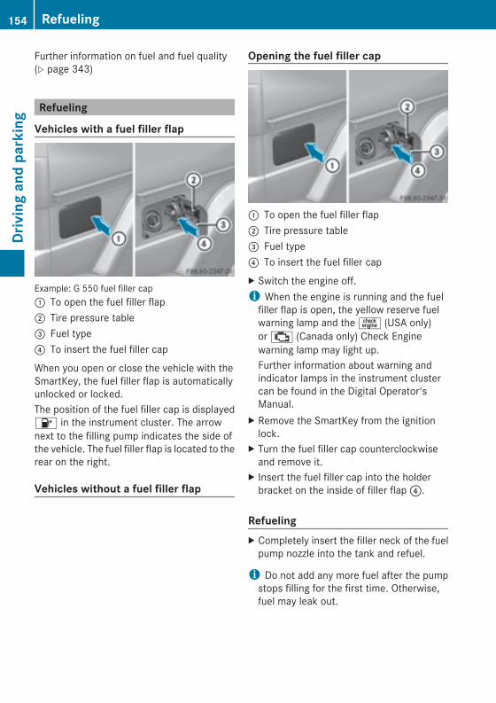
Further information on fuel and fuel quality(Y page 343)
Refueling
Vehicles with a fuel filler flap
Example: G 550 fuel filler cap: To open the fuel filler flap; Tire pressure table= Fuel type? To insert the fuel filler cap
When you open or close the vehicle with theSmartKey, the fuel filler flap is automaticallyunlocked or locked.The position of the fuel filler cap is displayed8 in the instrument cluster. The arrownext to the filling pump indicates the side ofthe vehicle. The fuel filler flap is located to therear on the right.
Vehicles without a fuel filler flap
Opening the fuel filler cap
: To open the fuel filler flap; Tire pressure table= Fuel type? To insert the fuel filler capX Switch the engine off.i When the engine is running and the fuelfiller flap is open, the yellow reserve fuelwarning lamp and the= (USA only)or; (Canada only) Check Enginewarning lamp may light up.Further information about warning andindicator lamps in the instrument clustercan be found in the Digital Operator'sManual.
X Remove the SmartKey from the ignitionlock.
X Turn the fuel filler cap counterclockwiseand remove it.
X Insert the fuel filler cap into the holderbracket on the inside of filler flap?.
RefuelingX Completely insert the filler neck of the fuelpump nozzle into the tank and refuel.
i Do not add any more fuel after the pumpstops filling for the first time. Otherwise,fuel may leak out.
154 RefuelingDrivingandparking
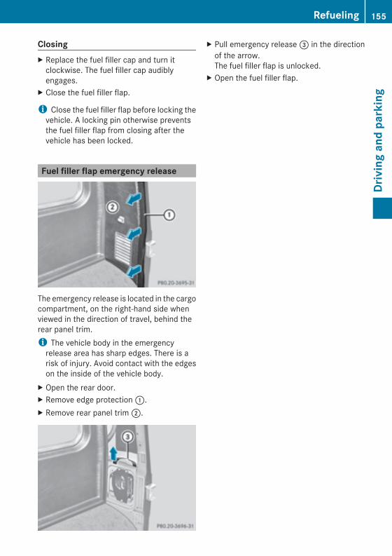
ClosingX Replace the fuel filler cap and turn itclockwise. The fuel filler cap audiblyengages.
X Close the fuel filler flap.
i Close the fuel filler flap before locking thevehicle. A locking pin otherwise preventsthe fuel filler flap from closing after thevehicle has been locked.
Fuel filler flap emergency release
The emergency release is located in the cargocompartment, on the right-hand side whenviewed in the direction of travel, behind therear panel trim.i The vehicle body in the emergencyrelease area has sharp edges. There is arisk of injury. Avoid contact with the edgeson the inside of the vehicle body.
X Open the rear door.X Remove edge protection:.X Remove rear panel trim;.
X Pull emergency release= in the directionof the arrow.The fuel filler flap is unlocked.
X Open the fuel filler flap.
Refueling 155
Drivingandparking
Z
Problems with the fuel and fuel tank
Problem Possible causes/consequences andMM Solutions
Fuel is leaking from thevehicle.
G Risk of explosion or fireThe fuel line or the fuel tank is defective.X Turn the SmartKey to position 0(Y page 139) in the ignition lockimmediately and remove it.
X Do not restart the engine under any circumstances.X Consult a qualified specialist workshop.
The fuel filler flapcannot be opened.
The fuel filler flap is not unlocked.orThe SmartKey batteries are discharged.X Unlock the vehicle (Y page 68).orX Unlock the vehicle using the mechanical key (Y page 70).X Open the rear door.X Manually unlock the fuel filler flap using the emergency release(Y page 155).
The fuel filler flap is unlocked, but the opening mechanism isjammed.X Manually unlock the fuel filler flap using the emergency release(Y page 155).
X Consult a qualified specialist workshop.
Parking
Important safety notes
G WARNINGIf you leave children unsupervised in thevehicle, they could set it in motion by, forexample:Rrelease the parking brake.Rshift the automatic transmission out of theparking position P.Rstart the engine.In addition, they may operate vehicleequipment and become trapped. There is arisk of an accident and injury.
When leaving the vehicle, always take theSmartKeywith you and lock the vehicle. Neverleave children unsupervised in the vehicle.
G WARNINGFlammable material such as leaves, grass ortwigsmay ignite if they come into contactwithhot parts of the exhaust system or exhaustgas flow. There is a risk of fire.Park the vehicle so that no flammablematerials come into contact with parts of thevehicle which are hot. Take particular care notto park on dry grassland or harvested grainfields.
156 ParkingDrivingandparking
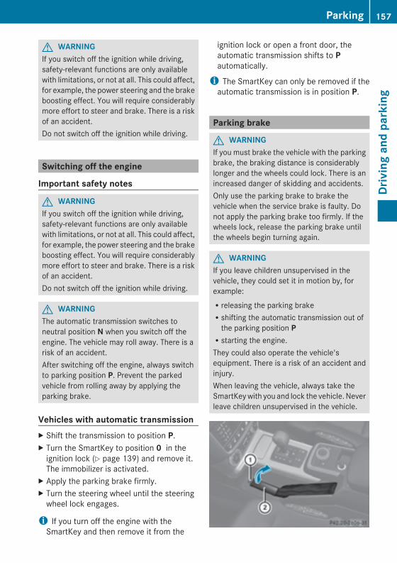
G WARNINGIf you switch off the ignition while driving,safety-relevant functions are only availablewith limitations, or not at all. This could affect,for example, the power steering and the brakeboosting effect. You will require considerablymore effort to steer and brake. There is a riskof an accident.Do not switch off the ignition while driving.
Switching off the engine
Important safety notes
G WARNINGIf you switch off the ignition while driving,safety-relevant functions are only availablewith limitations, or not at all. This could affect,for example, the power steering and the brakeboosting effect. You will require considerablymore effort to steer and brake. There is a riskof an accident.Do not switch off the ignition while driving.
G WARNINGThe automatic transmission switches toneutral position N when you switch off theengine. The vehicle may roll away. There is arisk of an accident.After switching off the engine, always switchto parking position P. Prevent the parkedvehicle from rolling away by applying theparking brake.
Vehicles with automatic transmissionX Shift the transmission to position P.X Turn the SmartKey to position 0 in theignition lock (Y page 139) and remove it.The immobilizer is activated.
X Apply the parking brake firmly.X Turn the steering wheel until the steeringwheel lock engages.
i If you turn off the engine with theSmartKey and then remove it from the
ignition lock or open a front door, theautomatic transmission shifts to Pautomatically.
i The SmartKey can only be removed if theautomatic transmission is in position P.
Parking brake
G WARNINGIf you must brake the vehicle with the parkingbrake, the braking distance is considerablylonger and the wheels could lock. There is anincreased danger of skidding and accidents.Only use the parking brake to brake thevehicle when the service brake is faulty. Donot apply the parking brake too firmly. If thewheels lock, release the parking brake untilthe wheels begin turning again.
G WARNINGIf you leave children unsupervised in thevehicle, they could set it in motion by, forexample:Rreleasing the parking brakeRshifting the automatic transmission out ofthe parking position PRstarting the engine.They could also operate the vehicle'sequipment. There is a risk of an accident andinjury.When leaving the vehicle, always take theSmartKeywith you and lock the vehicle. Neverleave children unsupervised in the vehicle.
Parking 157
Drivingandparking
Z
i When you apply parking brake; to brakethe vehicle, the brake lamps do not light up.
X To apply: pull parking brake; up firmly.Parking brake; is applied.When the ignition is switched on or theengine is running, theF (USA only) orJ (Canada only) indicator lamp is lit inthe instrument cluster.
X To release: depress the brake pedal andkeep it depressed.The selector lever lock is released.
X Pull parking brake; up firmly.X Press release button: on parkingbrake; and move parking brake; downto the stop.When the ignition is switched on or theengine is running, theF (USA only)or! (Canada only) indicator lamp goesout in the instrument cluster.
i If you pull away with parking brake;applied, a warning tone sounds.
Parking the vehicle for a long periodIf you leave the vehicle parked for longer thanfour weeks, the battery may be damaged byexhaustive discharge.X Connecting a trickle charger.i You can obtain information about tricklechargers from a qualified specialistworkshop.
If you leave the vehicle parked for longer thansix weeks, the vehicle may suffer damage asa result of lack of use.X Visit a qualified specialist workshop andseek advice.
Driving tips
General driving tips
Important safety notes
G WARNINGAlways remember that you must concentrateprimarily on driving the vehicle. The driver'sconcentration must always be directedprimarily at road traffic. For your own safetyand that of others, we recommend that youstop the vehicle at a safe place and inaccordance with the traffic conditions beforemaking or accepting a phone call.Comply with all legal requirements if you usethe telephone while driving. Use the hands-free system and only use the telephone whenroad, weather and traffic conditions permit. Insome jurisdictions, it is forbidden for driversto use mobile phones while driving.Only operateCOMAND (CockpitManagementand Data System) in compliance with all legalrequirements andwhen the road,weather andtraffic conditions permit. You may otherwisenot be able to observe the traffic conditions,endangering yourself and others.Remember that your vehicle covers a distanceof 44 ft (approximately 14 m) a second whenit is traveling at only 30 mph (approximately50 km/h).
G WARNINGIf you switch off the ignition while driving,safety-relevant functions are only availablewith limitations, or not at all. This could affect,for example, the power steering and the brakeboosting effect. You will require considerablymore effort to steer and brake. There is a riskof an accident.Do not switch off the ignition while driving.
158 Driving tipsDrivingandparking
Drive sensibly – save fuelObserve the following tips to save fuel:X The tires should always be inflated to therecommended tire pressure.
X Remove unnecessary loads.X Remove roof carriers when they are notneeded.
X Warm up the engine at low engine speeds.X Avoid frequent acceleration or braking.X Have all maintenance work performed atthe service intervals specified in theMaintenance Booklet or indicated by theservice interval indicator.
Fuel consumption also increases whendriving in cold weather, in stop-and-go trafficand in mountainous terrain.
Drinking and driving
G WARNINGDrinking and driving and/or taking drugs anddriving are very dangerous combinations.Even a small amount of alcohol or drugs canaffect your reflexes, perceptions andjudgment.The possibility of a serious or even fatalaccident are greatly increasedwhen you drinkor take drugs and drive.Do not drink or take drugs and drive or allowanyone to drive who has been drinking ortaking drugs.
Pedals
G WARNINGObjects in the driver's footwell can restrict thepedal travel or obstruct a depressed pedal.The operating and road safety of the vehicleis jeopardized. There is a risk of an accident.Make sure that all objects in the vehicle arestowed correctly, and that they cannot enterthe driver's footwell. Install the floormatssecurely and as specified in order to ensuresufficient clearance for the pedals. Do not useloose floormats.
Exhaust check
G WARNINGInhalation of exhaust gas is hazardous to yourhealth. All exhaust gas contains carbonmonoxide (CO), and inhaling it can causeunconsciousness and possible death.Do not run the engine in confined areas (suchas a garage) which are not properly ventilated.If you think that exhaust gas fumes areentering the vehicle while driving, have thecause determined and correctedimmediately. If you must drive under theseconditions, drive only with at least onewindow fully open at all times.
Certain engine systems are designed to keepthe level of poisonous components in exhaustfumes within legal limits.These systems only work at peak efficiency ifthey are serviced exactly in accordance withthe manufacturer's specifications. For thisreason, all work on the engine should only becarried out by qualified and authorizedMercedes-Benz technicians.The engine settings must not be changedunder any circumstances. Furthermore, allspecific service work must be carried out atregular intervals and in accordance with theMercedes-Benz service requirements. Detailscan be found in the Maintenance Booklet.
Braking
Important safety notes
G WARNINGIf you activate the LOW off-road gear whiledriving on a slippery road surface, the wheelsmay lose traction:Rif you remove your foot from theaccelerator pedal when drivingRif off road ABS intervenes when brakingIf the wheels lose traction. the vehicle can nolonger be steered. There is an increaseddanger of skidding and accidents.
Driving tips 159
Drivingandparking
Z
Never activate the LOW off-road gear whiledriving on a slippery road surface.
Downhill gradients! On long and steep gradients, you mustreduce the load on the brakes by shiftingearly to a lower gear. This allows you to takeadvantage of the engine braking effect andhelps avoid overheating and excessivewear of the brakes.When you take advantage of the enginebraking effect, a drive wheel may not turnfor some time, e.g. on a slippery roadsurface. This could cause damage to thedrive train. This type of damage is notcovered by the Mercedes-Benz warranty.
Heavy and light loads
G WARNINGIf you rest your foot on the brake pedal whiledriving, the braking system can overheat. Thisincreases the stopping distance and can evencause the braking system to fail. There is arisk of an accident.Never use the brake pedal as a footrest. Neverdepress the brake pedal and the acceleratorpedal at the same time.
! Depressing the brake pedal constantlyresults in excessive and premature wear tothe brake pads.
If the brakes have been subjected to a heavyload, do not stop the vehicle immediately, butdrive on for a short while. This allows theairflow to cool the brakes more quickly.
Wet roadsIf driving in heavy rain for a prolonged periodof time without braking, there may be adelayed reaction from the brakes whenbraking for the first time. This may also occurafter the vehicle has been washed.
You have to depress the brake pedal morefirmly. Maintain a greater distance from thevehicle in front.After driving on a wet road or having thevehicle washed, brake firmly while payingattention to the traffic conditions. This willwarm up the brake discs, thereby drying themmore quickly and protecting them againstcorrosion.
Limited braking performance on salt-treated roadsIf you drive on salted roads, a layer of saltresidue may form on the brake discs andbrake pads. This can result in a significantlylonger braking distance.RBrake occasionally to remove any possiblesalt residue. Make sure that you do notendanger other road users when doing so.RCarefully depress the brake pedal and thebeginning and end of a journey.RMaintain a greater distance to the vehicleahead.
Servicing the brakes! If the brake warning lamp lights up in theinstrument cluster and you hear a warningtone even though the parking brake hasbeen released, the brake fluid level may betoo low. Observe additional warningmessages in the multifunction display.The brake fluid level may be too low due tobrake pad wear or leaking brake lines.Have the brake system checkedimmediately. This work should be carriedout at a qualified specialist workshop.
! A function or performance test shouldonly be carried out on a 2-axledynamometer. If you are planning to havethe vehicle tested on such a dynamometer,contact an authorized Mercedes-BenzCenter to obtain further information first.Otherwise, you could damage the drivetrain or the brake system.
160 Driving tipsDrivingandparking
! As the ESP® system operatesautomatically, the engine and the ignitionmust be switched off (the SmartKey mustbe in position 0 or 1 in the ignition lock) ifthe parking brake is tested on a brakedynamometer (for a maximum of tenseconds).Braking applications triggeredautomatically by ESP® may otherwiseseriously damage the brake system.
Mercedes-Benz recommends that you onlyhave brake pads/linings installed on yourvehicle which have been approved forMercedes-Benz vehicles or which correspondto an equivalent quality standard. Brakepads/linings which have not been approvedfor Mercedes-Benz vehicles or which are notof an equivalent quality could affect yourvehicle's operating safety.Mercedes-Benz recommends that you onlyuse brake fluid that has been speciallyapproved for your vehicle by Mercedes-Benz,or which corresponds to an equivalent qualitystandard. Brake fluid which has not beenapproved for Mercedes-Benz vehicles orwhich is not of an equivalent quality couldaffect your vehicle's operating safety.All checks and maintenance work on thebrake system must be carried out at aqualified specialist workshop.Have brake pads installed and brake fluidreplaced at a qualified specialist workshop.If your brake system is subject only tomoderate loads, you should test thefunctionality of your brakes at regularintervals by pressing firmly on the brake pedalat high speeds. This improves the grip of thebrake pads.You can find a description of Brake Assist(BAS) on (Y page 61).
High-performance brake system forAMG vehiclesThe high-performance brake system is onlyinstalled on the G 63 AMG and the G 65 AMG.
The high-performance brake system isdesigned for heavy loads. This may lead tonoise when braking. This will depend on:RSpeedRBraking forceREnvironmental conditions, such astemperature and humidity
The wear of individual components of thebrake system, such as the brake pads/liningsor brake discs, depends on the individualdriving style and operating conditions.For this reason, it is impossible to state amileage that will be valid under allcircumstances. An aggressive driving stylewill lead to high wear. You can obtain furtherinformation about this from your authorizedMercedes-Benz Center.New and replaced brake pads and discs onlyreach their optimum braking effect afterseveral hundred kilometers of driving.Compensate for this by applying greater forceto the brake pedal. Keep this in mind, andadapt your driving and braking accordinglyduring this break-in period.Excessive heavy braking results incorrespondingly high brake wear. Observethe brake system warning lamp in theinstrument cluster and note any brake statusmessages in the multifunction display. Forhigh-performance driving in particular, it isimportant to maintain and have the brakesystem checked regularly.
Parking brake
G WARNINGIf you must brake the vehicle with the parkingbrake, the braking distance is considerablylonger and the wheels could lock. There is anincreased danger of skidding and accidents.Only use the parking brake to brake thevehicle when the service brake is faulty. Donot apply the parking brake too firmly. If thewheels lock, release the parking brake untilthe wheels begin turning again.
Driving tips 161
Drivingandparking
Z
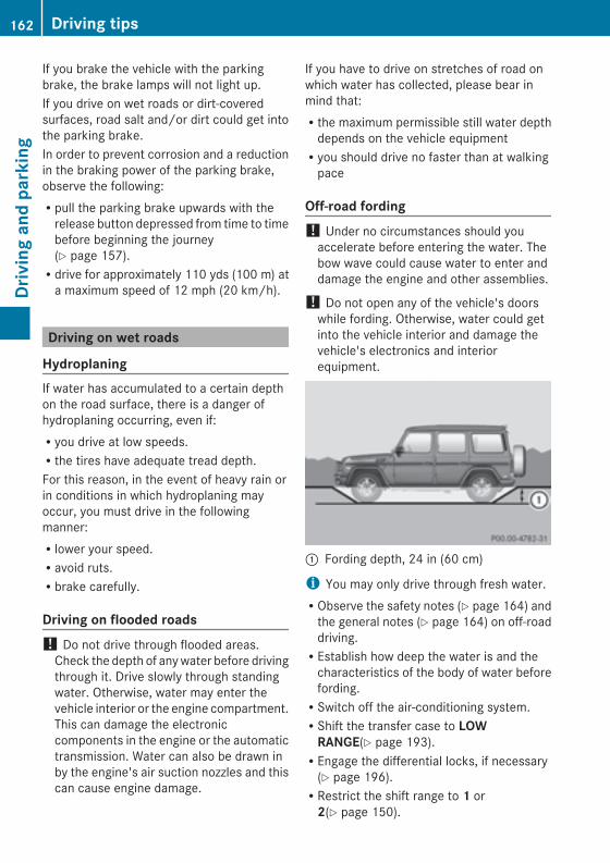
If you brake the vehicle with the parkingbrake, the brake lamps will not light up.If you drive on wet roads or dirt-coveredsurfaces, road salt and/or dirt could get intothe parking brake.In order to prevent corrosion and a reductionin the braking power of the parking brake,observe the following:Rpull the parking brake upwards with therelease button depressed from time to timebefore beginning the journey(Y page 157).Rdrive for approximately 110 yds (100 m) ata maximum speed of 12 mph (20 km/h).
Driving on wet roads
HydroplaningIf water has accumulated to a certain depthon the road surface, there is a danger ofhydroplaning occurring, even if:Ryou drive at low speeds.Rthe tires have adequate tread depth.For this reason, in the event of heavy rain orin conditions in which hydroplaning mayoccur, you must drive in the followingmanner:Rlower your speed.Ravoid ruts.Rbrake carefully.
Driving on flooded roads! Do not drive through flooded areas.Check the depth of anywater before drivingthrough it. Drive slowly through standingwater. Otherwise, water may enter thevehicle interior or the engine compartment.This can damage the electroniccomponents in the engine or the automatictransmission. Water can also be drawn inby the engine's air suction nozzles and thiscan cause engine damage.
If you have to drive on stretches of road onwhich water has collected, please bear inmind that:Rthe maximum permissible still water depthdepends on the vehicle equipmentRyou should drive no faster than at walkingpace
Off-road fording! Under no circumstances should youaccelerate before entering the water. Thebow wave could cause water to enter anddamage the engine and other assemblies.
! Do not open any of the vehicle's doorswhile fording. Otherwise, water could getinto the vehicle interior and damage thevehicle's electronics and interiorequipment.
: Fording depth, 24 in (60 cm)
i You may only drive through fresh water.RObserve the safety notes (Y page 164) andthe general notes (Y page 164) on off-roaddriving.REstablish how deep the water is and thecharacteristics of the body of water beforefording.RSwitch off the air-conditioning system.RShift the transfer case to LOWRANGE(Y page 193).REngage the differential locks, if necessary(Y page 196).RRestrict the shift range to 1 or2(Y page 150).
162 Driving tipsDrivingandparking
RAvoid high engine speeds.REnter and exit the water at a flat place andat a steady walking pace.RDrive slowly and at an even speed throughthe water.RDo not stop and do not switch off theengine.RWater offers a high degree of resistance,and the ground is slippery and in somecases unstable. Therefore, it is difficult anddangerous to pull away in the water.REnsure that a bow wave does not form asyou drive.RClean any mud from the tire tread afterfording.RApply the brakes to dry them after fording.Always observe the fording depth values(Y page 350).
Winter driving
General notes
G DANGERIf the exhaust pipe is blocked or adequateventilation is not possible, poisonous gasessuch as carbon monoxide (CO) may enter thevehicle. This is the case, e.g. if the vehiclebecomes trapped in snow. There is a risk offatal injury.If you leave the engine or the auxiliary heatingrunning, make sure the exhaust pipe and areaaround the vehicle are clear of snow. Toensure an adequate supply of fresh air, opena window on the side of the vehicle that is notfacing into the wind.
G WARNINGIf snow chains are installed to the frontwheels, they may drag against the vehiclebody or chassis components. This couldcause damage to the vehicle or the tires.There is a risk of an accident.
To avoid hazardous situations:Rnever install snow chains to the frontwheelsRalways install snow chains in pairs to therear wheels.
Have your vehicle winterproofed at a qualifiedspecialist workshop at the onset of winter.Observe the notes in the "Winter operation"section (Y page 314).
Driving with summer tiresObserve the notes in the "Winter operation"section (Y page 314).
Slippery road surfaces
G WARNINGIf you shift down on a slippery road surface inan attempt to increase the engine's brakingeffect, the drive wheels could lose their grip.There is an increased danger of skidding andaccidents.Do not shift down for additional enginebraking on a slippery road surface.
G WARNINGThe outside temperature indicator is notdesigned to serve as an ice-warning deviceand is therefore unsuitable for that purpose.Indicated temperatures just above thefreezing point do not guarantee that the roadsurface is free of ice. The roadmay still be icy,especially in wooded areas or on bridges.
G WARNINGIf you activate the LOW off-road gear whiledriving on a slippery road surface, the wheelsmay lose traction:Rif you remove your foot from theaccelerator pedal when drivingRif off road ABS intervenes when brakingIf the wheels lose traction. the vehicle can nolonger be steered. There is an increaseddanger of skidding and accidents.
Driving tips 163
Drivingandparking
Z
Never activate the LOW off-road gear whiledriving on a slippery road surface.
Drive particularly carefully on slippery roadsurfaces. Avoid sudden acceleration, steeringand braking maneuvers. Do not use cruisecontrol.If the vehicle threatens to skid or cannot bestopped when moving at low speed:X Shift the transmission to position N.X Try to bring the vehicle under control usingcorrective steering.i For more information on driving withsnow chains, see (Y page 315).
Off-road driving
Important safety notes
G WARNINGDo not load items on the basic carrier bars. Itmay cause instability during somemaneuverswhich could result in an accident.Drive slowly in unknown terrain. This willmake it easier to recognize unexpectedobstacles and avoid damage to the vehicle.To help avoid the vehicle rolling over, neverturn it around on steep inclines. If the vehiclecannot complete the attempted climb, back itdown in reverse gear.Do not drive along the side of a slope. Thevehicle might otherwise rollover. If in doing sothe vehicle begins to show a tendency to roll,immediately steer into a line of gravity(straight up or downhill).Never let the vehicle roll backwards in idle.You may lose control of the vehicle if you useonly the service brake. For information ondriving downhill, see "Driving downhill".
When driving off-road, sand, mud and water,possiblymixedwith oil, for example, could getinto the brakes. This could result in a reducedbraking effect or in total brake failure and alsoin increased wear and tear. The brakingcharacteristics change depending on the
material ingressing the brakes. Clean thebrakes after driving off-road. If you detect areduced braking effect or grinding noises,have the brake system checked in a qualifiedspecialist workshop as soon as possible.Adapt your driving style to the differentbraking characteristics.Driving off-road increases the likelihood ofdamage to the vehicle, which, in turn, can leadto failure of the mechanical assembly orsystems. Adapt your driving style to suit theterrain conditions. Drive carefully. Havedamage to the vehicle rectified immediatelyat a qualified specialist workshop.
General notes
H Environmental noteProtection of the environment is of primaryimportance. Treat nature with respect.Observe all prohibiting signs.
Read this section carefully before driving yourvehicle off-road. Practice by driving overmoregentle off-road terrain first.Familiarize yourself with the characteristicsof your vehicle and the gear shift operationbefore driving through difficult terrain.The following driving systems are speciallyadapted to off-road driving:R4ETS (Y page 62)RTransfer case (Y page 193)RDifferential locks (Y page 195)Observe the following notes:Rstop your vehicle and, if necessary, shift thetransfer case to LOWRANGE(Y page 194) before driving off-road.RAMG vehicles: to shift the transfer case toLOW RANGE, deactivate the ECO start/stop function (Y page 142).Rengage the differential locks, if necessary(Y page 196).
i ABS, 4ETS, ESP® and BAS are deactivatedwhen the differential locks are activated.
164 Driving tipsDrivingandparking
This allows the front wheels to lock briefly,so that these can dig into a loose surface.However, please note that locked wheelsskid and can no longer steer.RCheck that items of luggage and loads arestowed safely and are well secured(Y page 261).RTo avoid damaging the vehicle, make surethere is always sufficient ground clearance.RAlways keep the engine running and in gearwhen driving on a downhill gradient.RAlways keep the engine running and in gearwhen driving on a slope.RDrive slowly and evenly, if necessary at awalking pace.REnsure that the wheels are in contact withthe ground at all times.RDrive with extreme care on unfamiliar off-road routes where visibility is poor. Forsafety reasons, get out of the vehicle firstand survey the off-road route.RCheck the depth of water before fordingrivers and streams.RWhen fording, do not stop and do notswitch off the engine.RLook out for obstacles, such as rocks,holes, tree stumps and furrows.RAlways keep the doors, rear door, sidewindows and the sliding sunroof closedwhile the vehicle is in motion.RSwitch off cruise control.RDo not stray from marked routes or paths.RAdapt your speed to the terrain. Therougher, steeper or more ruts on theterrain, the slower your speed should be.RDrive slowly and at an even speed throughthe water. Ensure that a bowwave does notform as you drive.ROn sand, drive quickly to overcome therolling resistance. Otherwise the vehicle'swheels could become stuck in looseground.RDo not jump with the vehicle as this willinterrupt the vehicle's propulsion.
RAvoid high engine speeds. Drive atappropriate engine speeds (maximum3,000 rpm).RDo not shift the automatic transmission totransmission position N.RAlways check the vehicle for damage afteroff-road driving.
i Information about retrofitting special all-terrain tires is available from any qualifiedspecialist workshop.
i Do not use the HOLD function whendriving off-road, on steep uphill or downhillgradients or on slippery or loose surfaces.The HOLD function cannot hold the vehicleon such surfaces.
Checklist before driving off-road! If the engine oil warning lamp lights upwhile the vehicle is in motion, stop thevehicle in a safe place as soon as possible.Check the engine oil level. The engine oilwarning lampwarningmust not be ignored.Continuing the journey while the symbol isdisplayed could lead to engine damage.
X Engine oil level: check the engine oil leveland add oil if necessary.Only then does the engine receive enoughoil when the vehicle is standing on a steepincline.
X Tire-changing tool kit: check that the jackis working and make sure you have the lugwrench, a robust tow cable and a foldingspade in the vehicle.
X Wheels and tires: check the tire treaddepth and tire pressure.
X Check for damage and remove any foreignobjects, e.g. small stones, from thewheels/tires.
X Replace any missing valve caps.X Replace dented or damaged wheels.X Carry a sound spare wheel.
Driving tips 165
Drivingandparking
Z
Checklist after driving off-roadDriving over rough terrain places greaterdemands on your vehicle than driving onnormal roads. After driving off-road, checkthe vehicle. This allows you to detect damagepromptly and reduce the risk of an accidentto yourself and other road users.X Shift the transfer case to HIGHRANGE(Y page 194).
X Disengage the differential locks(Y page 198).
X Clean the headlamps and rear lights andcheck for damage.
X Clean the front and rear license plates.X Clean the wheels and tires with a water jetand remove any foreign objects.
X Clean thewheels, tires, wheel housings andthe vehicle underside with a water jet;check for any foreign objects and damage.
X Check whether twigs or other parts ofplants have become trapped. Theseincrease the risk of fire and can damagefuel pipes, brake hoses or the rubberbellows of the axle joints and propellershafts.
X After the trip, examine without fail theentire undercarriage, wheels, tires, brakes,bodywork structure, steering, chassis andexhaust system for damage.
X After driving for extended periods acrosssand, mud, gravel, water or in similarly dirtyconditions, have the brake discs, wheels,brake pads/linings and axle joints checkedand cleaned.
X If you notice strong vibrations after off-roaddriving, check for foreign objects in thewheels and drive train and, if necessary,remove them.Foreign objects can disturb the balanceand cause vibrations.
X Test the brakes.
Driving on sandObserve the following rules when driving onsand:RShift the transfer case to LOWRANGE(Y page 194).RAvoid high engine speeds.RLimit the shift range of the automatictransmission according to the off-roadconditions.RDrive quickly to overcome the rollingresistance. Otherwise the vehicle's wheelscould become stuck in loose ground.RDrive in the tracks of other vehicles ifpossible. When doing so, make sure that:- the tire ruts are not too deep.- the sand is sufficiently firm.- your vehicle has sufficient groundclearance
Tire ruts and gravel roads! Check that the ruts are not too deep andthat your vehicle has sufficient clearance.Otherwise, your vehicle could be damagedor bottom out and get stuck.
Observe the following rules when drivingalong ruts in off-road terrain or on roads withloose gravel:RShift the transfer case to LOWRANGE(Y page 194).RAvoid high engine speeds.RObserve the safety notes (Y page 164) andthe general notes (Y page 164) on off-roaddriving.RRestrict the shift range of the automatictransmission to 1(Y page 150).RDrive slowly.RWhere ruts are too deep, drive with thewheels of one side on the center grassyarea, if possible.
166 Driving tipsDrivingandparking
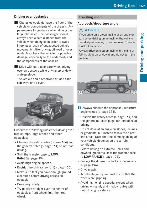
Driving over obstacles! Obstacles could damage the floor of thevehicle or components of the chassis. Askpassengers for guidance when driving overlarge obstacles. The passenger shouldalways keep a safe distance from thevehicle when doing so in order to avoidinjury as a result of unexpected vehiclemovements. After driving off-road or overobstacles, check the vehicle for possibledamage, especially to the underbody andthe components of the chassis.
! Drive with particular care when drivingover an obstacle while driving up or downa steep slope.The vehicle could otherwise tilt and slidesideways or tip over.
Observe the following rules when driving overtree stumps, large stones and otherobstacles:RObserve the safety notes (Y page 164) andthe general notes (Y page 164) on off-roaddriving.RShift the transfer case to LOWRANGE(Y page 194).RAvoid high engine speeds.RRestrict the shift range to 1(Y page 150).RMake sure that you have enough groundclearance before driving across anobstacle.RDrive very slowly.RTry to drive straight over the center ofobstacles: front wheel first, then rearwheel.
Traveling uphill
Approach/departure angle
G WARNINGIf you drive on a steep incline at an angle orturn when driving on an incline, the vehiclecould slip sideways, tip and rollover. There isa risk of an accident.Always drive on a steep incline in the line offall (straight up or down) and do not turn thevehicle.
i Always observe the approach/departureangle values (Y page 351).RObserve the safety notes (Y page 164) andthe general notes (Y page 164) on off-roaddriving.RDo not drive at an angle on slopes, inclinesor gradients, but instead follow the directline of fall. Note that the climbing ability ofyour vehicle depends on the terrainconditions.RBefore driving on extreme uphill anddownhill gradients, shift the transfer caseto LOW RANGE(Y page 194).REngage the differential locks, if necessary(Y page 196).RDrive slowly.RAccelerate gently and make sure that thewheels are gripping.RAvoid high engine speeds, except whendriving on sandy and muddy routes withhigh driving resistance.
Driving tips 167
Drivingandparking
Z
RAvoid high engine speeds – drive at anappropriate engine speed (maximum3,000 rpm).RWhen driving down an incline, make use ofthe engine's braking effect. Observe theengine speed; do not overrev the engine.
i Further information on the maximumengine speed: (Y page 206).RSelect a shift range appropriate to thegradient.RBefore tackling steep downhill gradients,select shift range 1(Y page 150).RAlways check the brakes after driving off-road.
i Hill start assist will aid you when pullingaway on a hill.For more information, see "Hill start assist"(Y page 141).
Maximum gradient-climbing capabilityAccelerate carefully and make sure that thewheels do not spin when driving on steepterrain.
i If the load on the front axle is reducedwhen pulling away on a steep uphill slope,the front wheels have a tendency to spin.4ETS detects this and brakes the wheelsaccordingly. The rear wheel torque isincreased, making it easier to drive off.
Always observe the maximum gradientclimbing ability values (Y page 351).
HilltopsWhen driving on an uphill gradient, reducepressure slightly on the acceleratorimmediately before reaching the top of the hill(do not shift the transmission to position N).Use the vehicle's own impetus to drive overthe top of the hill.
This style of driving prevents:Rthe vehicle from lifting off the ground on thebrow of a hillRloss of tractionRthe vehicle from traveling too quickly downthe other side
Driving downhillRBefore tackling steep downhill gradients,select shift range 1(Y page 150).This way you use the engine's brakingeffect to reduce the speed. If this is notsufficient, brake gently. When doing so,make sure that the vehicle is facing in thedirection of the line of fall.RObserve the notes on driving inmountainous terrain (Y page 168).RDrive slowly.RDo not drive at an angle down steepinclines. Steer into the line of fall and drivewith the front wheels aligned straight.Otherwise, the vehicle could slip sideways,tip and roll over.RCheck that the brakes areworking normallyafter a long downhill stretch.
i The special off-road ABS setting(Y page 61) enables repeated, brief,precise locking of the front wheels, whichleads to the wheels digging into the looseground. Note that when the front wheelsare fully braked, they slide easily over thesurface of the ground, making it difficult tosteer.
Driving systems
Cruise Control
Important safety notes
G WARNINGThe brake pedal moves when cruise controlbrakes the vehicle. A foot in the area underthe brake pedal could become trapped. Themovement of the pedal, and therefore the
168 Driving systemsDrivingandparking
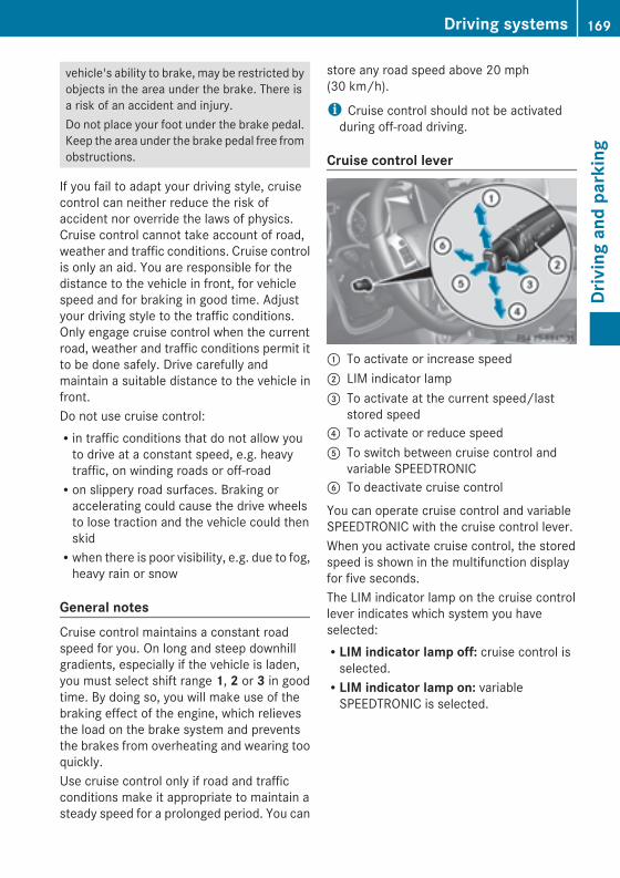
vehicle's ability to brake, may be restricted byobjects in the area under the brake. There isa risk of an accident and injury.Do not place your foot under the brake pedal.Keep the area under the brake pedal free fromobstructions.
If you fail to adapt your driving style, cruisecontrol can neither reduce the risk ofaccident nor override the laws of physics.Cruise control cannot take account of road,weather and traffic conditions. Cruise controlis only an aid. You are responsible for thedistance to the vehicle in front, for vehiclespeed and for braking in good time. Adjustyour driving style to the traffic conditions.Only engage cruise control when the currentroad, weather and traffic conditions permit itto be done safely. Drive carefully andmaintain a suitable distance to the vehicle infront.Do not use cruise control:Rin traffic conditions that do not allow youto drive at a constant speed, e.g. heavytraffic, on winding roads or off-roadRon slippery road surfaces. Braking oraccelerating could cause the drive wheelsto lose traction and the vehicle could thenskidRwhen there is poor visibility, e.g. due to fog,heavy rain or snow
General notesCruise control maintains a constant roadspeed for you. On long and steep downhillgradients, especially if the vehicle is laden,you must select shift range 1, 2 or 3 in goodtime. By doing so, you will make use of thebraking effect of the engine, which relievesthe load on the brake system and preventsthe brakes from overheating and wearing tooquickly.Use cruise control only if road and trafficconditions make it appropriate to maintain asteady speed for a prolonged period. You can
store any road speed above 20 mph(30 km/h).
i Cruise control should not be activatedduring off-road driving.
Cruise control lever
: To activate or increase speed; LIM indicator lamp= To activate at the current speed/last
stored speed? To activate or reduce speedA To switch between cruise control and
variable SPEEDTRONICB To deactivate cruise control
You can operate cruise control and variableSPEEDTRONIC with the cruise control lever.When you activate cruise control, the storedspeed is shown in the multifunction displayfor five seconds.The LIM indicator lamp on the cruise controllever indicates which system you haveselected:RLIM indicator lamp off: cruise control isselected.RLIM indicator lamp on: variableSPEEDTRONIC is selected.
Driving systems 169
Drivingandparking
Z

Activation conditionsTo activate cruise control, all of the followingactivation conditions must be fulfilled:Rthe parking brake must be released.Ryou are driving faster than 20 mph(30 km/h).RESP® must be active, but not intervening.Rthe transmission must be in position D.
Selecting cruise control
: To activate or increase speed; LIM indicator lamp= To activate at the current speed/last
stored speed? To activate or reduce speedA To switch between cruise control and
variable SPEEDTRONICB To deactivate cruise controlX Checkwhether LIM indicator lamp; is off.If it is off, cruise control is already selected.If it is not, press the cruise control lever inthe direction of arrowA.LIM indicator lamp; in the cruise controllever goes out. Cruise control is selected.
Storing and maintaining the currentspeed
Storing and maintaining
: To activate or increase speed; LIM indicator lamp= To activate at the current speed/last
stored speed? To activate or reduce speedA To switch between cruise control and
variable SPEEDTRONICB To deactivate cruise control
You can store the current speed if you aredriving faster than 20 mph (30 km/h).X Accelerate the vehicle to the desiredspeed.
X Briefly press the cruise control leverup: or down?.
X Remove your foot from the acceleratorpedal.Cruise control is activated. The vehicleautomatically maintains the stored speed.
i Cruise control may be unable to maintainthe stored speed on uphill and downhillgradients. The stored speed is resumedwhen the gradient levels out. Cruise controlmaintains the stored speed on downhillgradients by automatically applying thebrakes.
Calling up the last speed storedG WARNINGIf you call up the stored speed and it is lowerthan the current speed, the vehicle
170 Driving systemsDrivingandparking
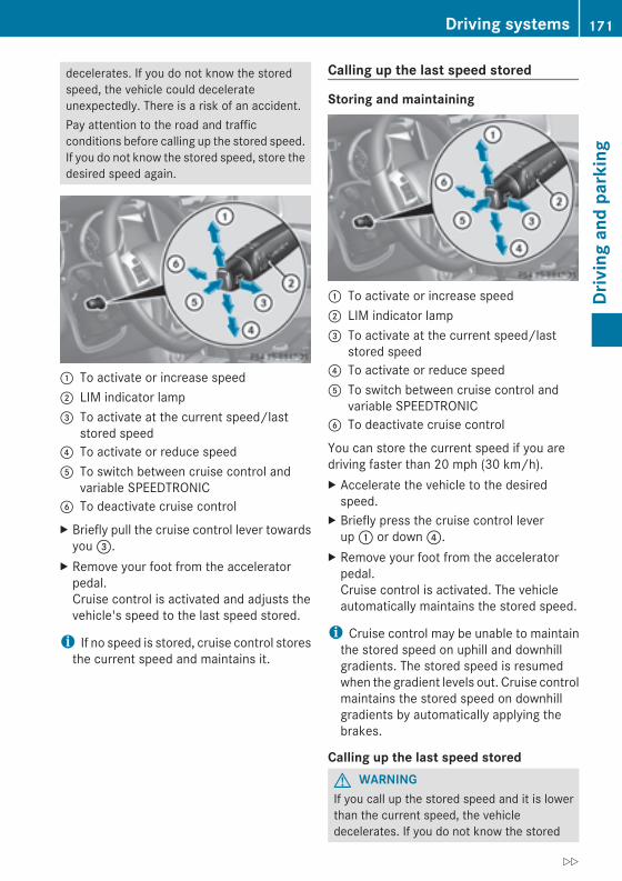
decelerates. If you do not know the storedspeed, the vehicle could decelerateunexpectedly. There is a risk of an accident.Pay attention to the road and trafficconditions before calling up the stored speed.If you do not know the stored speed, store thedesired speed again.
: To activate or increase speed; LIM indicator lamp= To activate at the current speed/last
stored speed? To activate or reduce speedA To switch between cruise control and
variable SPEEDTRONICB To deactivate cruise controlX Briefly pull the cruise control lever towardsyou=.
X Remove your foot from the acceleratorpedal.Cruise control is activated and adjusts thevehicle's speed to the last speed stored.
i If no speed is stored, cruise control storesthe current speed and maintains it.
Calling up the last speed stored
Storing and maintaining
: To activate or increase speed; LIM indicator lamp= To activate at the current speed/last
stored speed? To activate or reduce speedA To switch between cruise control and
variable SPEEDTRONICB To deactivate cruise control
You can store the current speed if you aredriving faster than 20 mph (30 km/h).X Accelerate the vehicle to the desiredspeed.
X Briefly press the cruise control leverup: or down?.
X Remove your foot from the acceleratorpedal.Cruise control is activated. The vehicleautomatically maintains the stored speed.
i Cruise control may be unable to maintainthe stored speed on uphill and downhillgradients. The stored speed is resumedwhen the gradient levels out. Cruise controlmaintains the stored speed on downhillgradients by automatically applying thebrakes.
Calling up the last speed storedG WARNINGIf you call up the stored speed and it is lowerthan the current speed, the vehicledecelerates. If you do not know the stored
Driving systems 171
Drivingandparking
Z
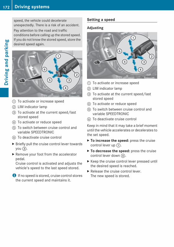
speed, the vehicle could decelerateunexpectedly. There is a risk of an accident.Pay attention to the road and trafficconditions before calling up the stored speed.If you do not know the stored speed, store thedesired speed again.
: To activate or increase speed; LIM indicator lamp= To activate at the current speed/last
stored speed? To activate or reduce speedA To switch between cruise control and
variable SPEEDTRONICB To deactivate cruise controlX Briefly pull the cruise control lever towardsyou=.
X Remove your foot from the acceleratorpedal.Cruise control is activated and adjusts thevehicle's speed to the last speed stored.
i If no speed is stored, cruise control storesthe current speed and maintains it.
Setting a speed
Adjusting
: To activate or increase speed; LIM indicator lamp= To activate at the current speed/last
stored speed? To activate or reduce speedA To switch between cruise control and
variable SPEEDTRONICB To deactivate cruise control
Keep in mind that it may take a brief momentuntil the vehicle accelerates or decelerates tothe set speed.X To increase the speed: press the cruisecontrol lever up:.
X To decrease the speed: press the cruisecontrol lever down?.
X Keep the cruise control lever pressed untilthe desired speed is reached.
X Release the cruise control lever.The new speed is stored.
172 Driving systemsDrivingandparking
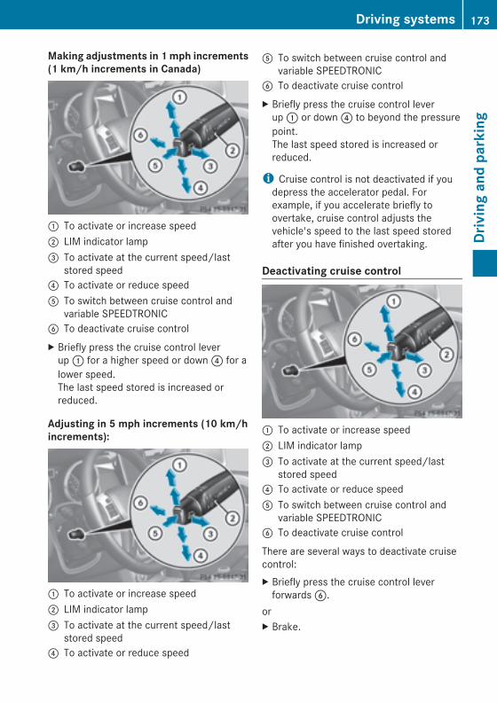
Making adjustments in 1mph increments(1 km/h increments in Canada)
: To activate or increase speed; LIM indicator lamp= To activate at the current speed/last
stored speed? To activate or reduce speedA To switch between cruise control and
variable SPEEDTRONICB To deactivate cruise controlX Briefly press the cruise control leverup: for a higher speed or down? for alower speed.The last speed stored is increased orreduced.
Adjusting in 5 mph increments (10 km/hincrements):
: To activate or increase speed; LIM indicator lamp= To activate at the current speed/last
stored speed? To activate or reduce speed
A To switch between cruise control andvariable SPEEDTRONIC
B To deactivate cruise controlX Briefly press the cruise control leverup: or down? to beyond the pressurepoint.The last speed stored is increased orreduced.
i Cruise control is not deactivated if youdepress the accelerator pedal. Forexample, if you accelerate briefly toovertake, cruise control adjusts thevehicle's speed to the last speed storedafter you have finished overtaking.
Deactivating cruise control
: To activate or increase speed; LIM indicator lamp= To activate at the current speed/last
stored speed? To activate or reduce speedA To switch between cruise control and
variable SPEEDTRONICB To deactivate cruise control
There are several ways to deactivate cruisecontrol:X Briefly press the cruise control leverforwardsB.
orX Brake.
Driving systems 173
Drivingandparking
Z
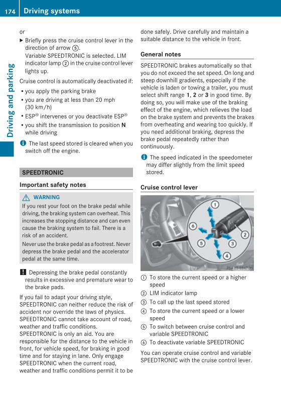
orX Briefly press the cruise control lever in thedirection of arrowA.Variable SPEEDTRONIC is selected. LIMindicator lamp; in the cruise control leverlights up.
Cruise control is automatically deactivated if:Ryou apply the parking brakeRyou are driving at less than 20 mph(30 km/h)RESP® intervenes or you deactivate ESP®Ryou shift the transmission to position Nwhile driving
i The last speed stored is cleared when youswitch off the engine.
SPEEDTRONIC
Important safety notes
G WARNINGIf you rest your foot on the brake pedal whiledriving, the braking system can overheat. Thisincreases the stopping distance and can evencause the braking system to fail. There is arisk of an accident.Never use the brake pedal as a footrest. Neverdepress the brake pedal and the acceleratorpedal at the same time.
! Depressing the brake pedal constantlyresults in excessive and premature wear tothe brake pads.
If you fail to adapt your driving style,SPEEDTRONIC can neither reduce the risk ofaccident nor override the laws of physics.SPEEDTRONIC cannot take account of road,weather and traffic conditions.SPEEDTRONIC is only an aid. You areresponsible for the distance to the vehicle infront, for vehicle speed, for braking in goodtime and for staying in lane. Only engageSPEEDTRONIC when the current road,weather and traffic conditions permit it to be
done safely. Drive carefully and maintain asuitable distance to the vehicle in front.
General notesSPEEDTRONIC brakes automatically so thatyou do not exceed the set speed. On long andsteep downhill gradients, especially if thevehicle is laden or towing a trailer, you mustselect shift range 1, 2 or 3 in good time. Bydoing so, you will make use of the brakingeffect of the engine, which relieves the loadon the brake system and prevents the brakesfrom overheating and wearing too quickly. Ifyou need additional braking, depress thebrake pedal repeatedly rather thancontinuously.
i The speed indicated in the speedometermay differ slightly from the limit speedstored.
Cruise control lever
: To store the current speed or a higherspeed
; LIM indicator lamp= To call up the last speed stored? To store the current speed or a lower
speedA To switch between cruise control and
variable SPEEDTRONICB To deactivate variable SPEEDTRONIC
You can operate cruise control and variableSPEEDTRONIC with the cruise control lever.
174 Driving systemsDrivingandparking

The LIM indicator lamp on the cruise controllever indicates which system you haveselected:RLIM indicator lamp off: cruise control isselected.RLIM indicator lamp on: variableSPEEDTRONIC is selected.
You can use the cruise control lever to limitthe speed to any speed above 30 km/hwhilethe engine is running.
Selecting variable SPEEDTRONIC
: To activate or increase speed; LIM indicator lamp= To activate at the current speed/last
stored speed? To activate or reduce speedA To switch between cruise control and
variable SPEEDTRONICB To deactivate cruise control
If you fail to adapt your driving style,SPEEDTRONIC can neither reduce the risk ofaccident nor override the laws of physics.SPEEDTRONIC cannot take account of road,weather and traffic conditions.SPEEDTRONIC is only an aid. You areresponsible for the distance to the vehicle infront, for vehicle speed, for braking in goodtime and for staying in lane. Only engageSPEEDTRONIC when the current road,weather and traffic conditions permit it to bedone safely. Drive carefully and maintain asuitable distance to the vehicle in front.X Checkwhether LIM indicator lamp; is on.
If it is on, variable SPEEDTRONIC is alreadyselected.If it is not, press the cruise control lever inthe direction of arrowA.LIM indicator lamp; in the cruise controllever lights up. Variable SPEEDTRONIC isselected.
Storing the current speed
: To activate or increase speed; LIM indicator lamp= To activate at the current speed/last
stored speed? To activate or reduce speedA To switch between cruise control and
variable SPEEDTRONICB To deactivate cruise control
You can use the cruise control lever to limitthe speed to any speed above 18 mph whilethe engine is running.X Briefly press the cruise control leverup: or down?.The current speed is stored and shown inthe multifunction display.
i On downhill gradients, the speed can beexceeded despite variable SPEEDTRONIC.In this case, you will hear a warning toneand the Limit ExceededLimit Exceeded message willappear in the multifunction display. Ifnecessary, apply the brakes yourself.
Driving systems 175
Drivingandparking
Z
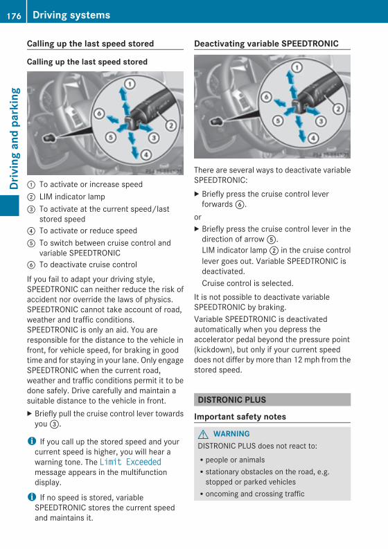
Calling up the last speed stored
Calling up the last speed stored
: To activate or increase speed; LIM indicator lamp= To activate at the current speed/last
stored speed? To activate or reduce speedA To switch between cruise control and
variable SPEEDTRONICB To deactivate cruise control
If you fail to adapt your driving style,SPEEDTRONIC can neither reduce the risk ofaccident nor override the laws of physics.SPEEDTRONIC cannot take account of road,weather and traffic conditions.SPEEDTRONIC is only an aid. You areresponsible for the distance to the vehicle infront, for vehicle speed, for braking in goodtime and for staying in your lane. Only engageSPEEDTRONIC when the current road,weather and traffic conditions permit it to bedone safely. Drive carefully and maintain asuitable distance to the vehicle in front.X Briefly pull the cruise control lever towardsyou=.
i If you call up the stored speed and yourcurrent speed is higher, you will hear awarning tone. The Limit ExceededLimit Exceededmessage appears in the multifunctiondisplay.
i If no speed is stored, variableSPEEDTRONIC stores the current speedand maintains it.
Deactivating variable SPEEDTRONIC
There are several ways to deactivate variableSPEEDTRONIC:X Briefly press the cruise control leverforwardsB.
orX Briefly press the cruise control lever in thedirection of arrowA.LIM indicator lamp; in the cruise controllever goes out. Variable SPEEDTRONIC isdeactivated.Cruise control is selected.
It is not possible to deactivate variableSPEEDTRONIC by braking.Variable SPEEDTRONIC is deactivatedautomatically when you depress theaccelerator pedal beyond the pressure point(kickdown), but only if your current speeddoes not differ by more than 12mph from thestored speed.
DISTRONIC PLUS
Important safety notes
G WARNINGDISTRONIC PLUS does not react to:Rpeople or animalsRstationary obstacles on the road, e.g.stopped or parked vehiclesRoncoming and crossing traffic
176 Driving systemsDrivingandparking
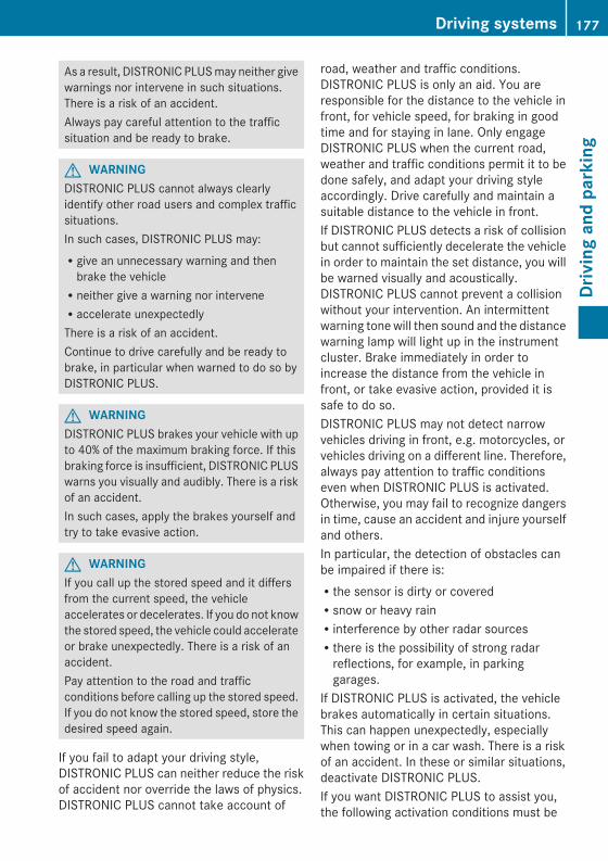
As a result, DISTRONIC PLUSmay neither givewarnings nor intervene in such situations.There is a risk of an accident.Always pay careful attention to the trafficsituation and be ready to brake.
G WARNINGDISTRONIC PLUS cannot always clearlyidentify other road users and complex trafficsituations.In such cases, DISTRONIC PLUS may:Rgive an unnecessary warning and thenbrake the vehicleRneither give a warning nor interveneRaccelerate unexpectedlyThere is a risk of an accident.Continue to drive carefully and be ready tobrake, in particular when warned to do so byDISTRONIC PLUS.
G WARNINGDISTRONIC PLUS brakes your vehicle with upto 40% of the maximum braking force. If thisbraking force is insufficient, DISTRONIC PLUSwarns you visually and audibly. There is a riskof an accident.In such cases, apply the brakes yourself andtry to take evasive action.
G WARNINGIf you call up the stored speed and it differsfrom the current speed, the vehicleaccelerates or decelerates. If you do not knowthe stored speed, the vehicle could accelerateor brake unexpectedly. There is a risk of anaccident.Pay attention to the road and trafficconditions before calling up the stored speed.If you do not know the stored speed, store thedesired speed again.
If you fail to adapt your driving style,DISTRONIC PLUS can neither reduce the riskof accident nor override the laws of physics.DISTRONIC PLUS cannot take account of
road, weather and traffic conditions.DISTRONIC PLUS is only an aid. You areresponsible for the distance to the vehicle infront, for vehicle speed, for braking in goodtime and for staying in lane. Only engageDISTRONIC PLUS when the current road,weather and traffic conditions permit it to bedone safely, and adapt your driving styleaccordingly. Drive carefully and maintain asuitable distance to the vehicle in front.If DISTRONIC PLUS detects a risk of collisionbut cannot sufficiently decelerate the vehiclein order to maintain the set distance, you willbe warned visually and acoustically.DISTRONIC PLUS cannot prevent a collisionwithout your intervention. An intermittentwarning tonewill then sound and the distancewarning lamp will light up in the instrumentcluster. Brake immediately in order toincrease the distance from the vehicle infront, or take evasive action, provided it issafe to do so.DISTRONIC PLUS may not detect narrowvehicles driving in front, e.g. motorcycles, orvehicles driving on a different line. Therefore,always pay attention to traffic conditionseven when DISTRONIC PLUS is activated.Otherwise, you may fail to recognize dangersin time, cause an accident and injure yourselfand others.In particular, the detection of obstacles canbe impaired if there is:Rthe sensor is dirty or coveredRsnow or heavy rainRinterference by other radar sourcesRthere is the possibility of strong radarreflections, for example, in parkinggarages.
If DISTRONIC PLUS is activated, the vehiclebrakes automatically in certain situations.This can happen unexpectedly, especiallywhen towing or in a car wash. There is a riskof an accident. In these or similar situations,deactivate DISTRONIC PLUS.If you want DISTRONIC PLUS to assist you,the following activation conditions must be
Driving systems 177
Drivingandparking
Z
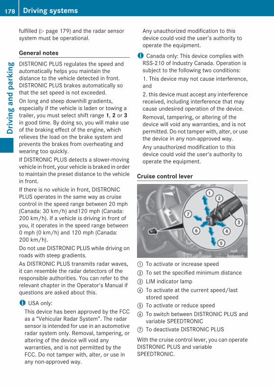
fulfilled (Y page 179) and the radar sensorsystem must be operational.
General notesDISTRONIC PLUS regulates the speed andautomatically helps you maintain thedistance to the vehicle detected in front.DISTRONIC PLUS brakes automatically sothat the set speed is not exceeded.On long and steep downhill gradients,especially if the vehicle is laden or towing atrailer, you must select shift range 1, 2 or 3in good time. By doing so, you will make useof the braking effect of the engine, whichrelieves the load on the brake system andprevents the brakes from overheating andwearing too quickly.If DISTRONIC PLUS detects a slower-movingvehicle in front, your vehicle is braked in orderto maintain the preset distance to the vehiclein front.If there is no vehicle in front, DISTRONICPLUS operates in the same way as cruisecontrol in the speed range between 20 mph(Canada: 30 km/h) and120 mph (Canada:200 km/h). If a vehicle is driving in front ofyou, it operates in the speed range between0 mph (0 km/h) and 120 mph (Canada:200 km/h).Do not use DISTRONIC PLUS while driving onroads with steep gradients.As DISTRONIC PLUS transmits radar waves,it can resemble the radar detectors of theresponsible authorities. You can refer to therelevant chapter in the Operator's Manual ifquestions are asked about this.
i USA only:This device has been approved by the FCCas a “Vehicular Radar System”. The radarsensor is intended for use in an automotiveradar system only. Removal, tampering, oraltering of the device will void anywarranties, and is not permitted by theFCC. Do not tamper with, alter, or use inany non-approved way.
Any unauthorized modification to thisdevice could void the user’s authority tooperate the equipment.
i Canada only: This device complies withRSS-210 of Industry Canada. Operation issubject to the following two conditions:1. This device may not cause interference,and2. this device must accept any interferencereceived, including interference that maycause undesired operation of the device.Removal, tampering, or altering of thedevice will void any warranties, and is notpermitted. Do not tamper with, alter, or usethe device in any non-approved way.Any unauthorized modification to thisdevice could void the user's authority tooperate the equipment.
Cruise control lever
: To activate or increase speed; To set the specified minimum distance= LIM indicator lamp? To activate at the current speed/last
stored speedA To activate or reduce speedB To switch between DISTRONIC PLUS and
variable SPEEDTRONICC To deactivate DISTRONIC PLUS
With the cruise control lever, you can operateDISTRONIC PLUS and variableSPEEDTRONIC.
178 Driving systemsDrivingandparking
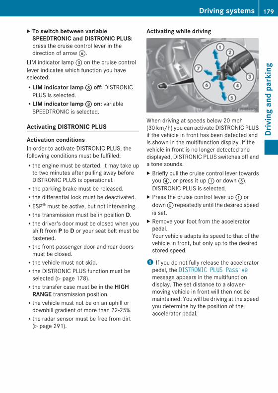
X To switch between variableSPEEDTRONIC and DISTRONIC PLUS:press the cruise control lever in thedirection of arrowB.
LIM indicator lamp= on the cruise controllever indicates which function you haveselected:RLIM indicator lamp== off: DISTRONICPLUS is selected.RLIM indicator lamp== on: variableSPEEDTRONIC is selected.
Activating DISTRONIC PLUS
Activation conditionsIn order to activate DISTRONIC PLUS, thefollowing conditions must be fulfilled:Rthe engine must be started. It may take upto two minutes after pulling away beforeDISTRONIC PLUS is operational.Rthe parking brake must be released.Rthe differential lock must be deactivated.RESP® must be active, but not intervening.Rthe transmission must be in position D.Rthe driver's door must be closed when youshift from P to D or your seat belt must befastened.Rthe front-passenger door and rear doorsmust be closed.Rthe vehicle must not skid.Rthe DISTRONIC PLUS function must beselected (Y page 178).Rthe transfer case must be in the HIGHRANGE transmission position.Rthe vehicle must not be on an uphill ordownhill gradient of more than 22-25%.Rthe radar sensor must be free from dirt(Y page 291).
Activating while driving
When driving at speeds below 20 mph(30 km/h) you can activate DISTRONIC PLUSif the vehicle in front has been detected andis shown in the multifunction display. If thevehicle in front is no longer detected anddisplayed, DISTRONIC PLUS switches off anda tone sounds.X Briefly pull the cruise control lever towardsyou?, or press it up: or downA.DISTRONIC PLUS is selected.
X Press the cruise control lever up: ordownA repeatedly until the desired speedis set.
X Remove your foot from the acceleratorpedal.Your vehicle adapts its speed to that of thevehicle in front, but only up to the desiredstored speed.
i If you do not fully release the acceleratorpedal, the DISTRONIC PLUS PassiveDISTRONIC PLUS Passivemessage appears in the multifunctiondisplay. The set distance to a slower-moving vehicle in front will then not bemaintained. You will be driving at the speedyou determine by the position of theaccelerator pedal.
Driving systems 179
Drivingandparking
Z
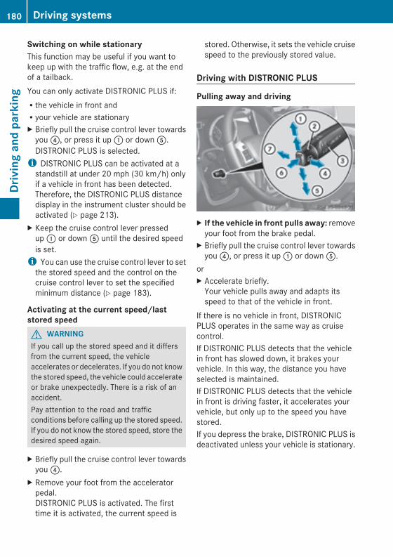
Switching on while stationaryThis function may be useful if you want tokeep up with the traffic flow, e.g. at the endof a tailback.You can only activate DISTRONIC PLUS if:Rthe vehicle in front andRyour vehicle are stationaryX Briefly pull the cruise control lever towardsyou?, or press it up: or downA.DISTRONIC PLUS is selected.i DISTRONIC PLUS can be activated at astandstill at under 20 mph (30 km/h) onlyif a vehicle in front has been detected.Therefore, the DISTRONIC PLUS distancedisplay in the instrument cluster should beactivated (Y page 213).
X Keep the cruise control lever pressedup: or downA until the desired speedis set.i You can use the cruise control lever to setthe stored speed and the control on thecruise control lever to set the specifiedminimum distance (Y page 183).
Activating at the current speed/laststored speedG WARNINGIf you call up the stored speed and it differsfrom the current speed, the vehicleaccelerates or decelerates. If you do not knowthe stored speed, the vehicle could accelerateor brake unexpectedly. There is a risk of anaccident.Pay attention to the road and trafficconditions before calling up the stored speed.If you do not know the stored speed, store thedesired speed again.
X Briefly pull the cruise control lever towardsyou?.
X Remove your foot from the acceleratorpedal.DISTRONIC PLUS is activated. The firsttime it is activated, the current speed is
stored. Otherwise, it sets the vehicle cruisespeed to the previously stored value.
Driving with DISTRONIC PLUS
Pulling away and driving
X If the vehicle in front pulls away: removeyour foot from the brake pedal.
X Briefly pull the cruise control lever towardsyou?, or press it up: or downA.
orX Accelerate briefly.Your vehicle pulls away and adapts itsspeed to that of the vehicle in front.
If there is no vehicle in front, DISTRONICPLUS operates in the same way as cruisecontrol.If DISTRONIC PLUS detects that the vehiclein front has slowed down, it brakes yourvehicle. In this way, the distance you haveselected is maintained.If DISTRONIC PLUS detects that the vehiclein front is driving faster, it accelerates yourvehicle, but only up to the speed you havestored.If you depress the brake, DISTRONIC PLUS isdeactivated unless your vehicle is stationary.
180 Driving systemsDrivingandparking
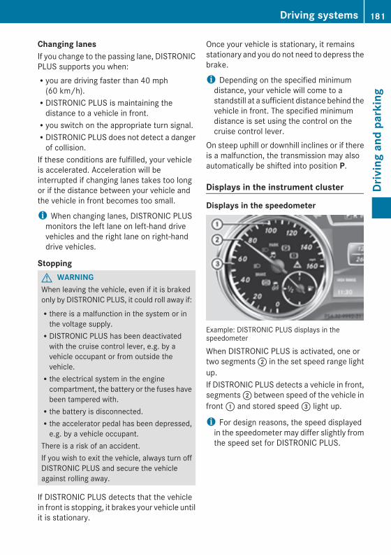
Changing lanesIf you change to the passing lane, DISTRONICPLUS supports you when:Ryou are driving faster than 40 mph(60 km/h).RDISTRONIC PLUS is maintaining thedistance to a vehicle in front.Ryou switch on the appropriate turn signal.RDISTRONIC PLUS does not detect a dangerof collision.
If these conditions are fulfilled, your vehicleis accelerated. Acceleration will beinterrupted if changing lanes takes too longor if the distance between your vehicle andthe vehicle in front becomes too small.
i When changing lanes, DISTRONIC PLUSmonitors the left lane on left-hand drivevehicles and the right lane on right-handdrive vehicles.
StoppingG WARNINGWhen leaving the vehicle, even if it is brakedonly by DISTRONIC PLUS, it could roll away if:Rthere is a malfunction in the system or inthe voltage supply.RDISTRONIC PLUS has been deactivatedwith the cruise control lever, e.g. by avehicle occupant or from outside thevehicle.Rthe electrical system in the enginecompartment, the battery or the fuses havebeen tampered with.Rthe battery is disconnected.Rthe accelerator pedal has been depressed,e.g. by a vehicle occupant.
There is a risk of an accident.If you wish to exit the vehicle, always turn offDISTRONIC PLUS and secure the vehicleagainst rolling away.
If DISTRONIC PLUS detects that the vehiclein front is stopping, it brakes your vehicle untilit is stationary.
Once your vehicle is stationary, it remainsstationary and you do not need to depress thebrake.
i Depending on the specified minimumdistance, your vehicle will come to astandstill at a sufficient distance behind thevehicle in front. The specified minimumdistance is set using the control on thecruise control lever.
On steep uphill or downhill inclines or if thereis a malfunction, the transmission may alsoautomatically be shifted into position P.
Displays in the instrument cluster
Displays in the speedometer
Example: DISTRONIC PLUS displays in thespeedometer
When DISTRONIC PLUS is activated, one ortwo segments; in the set speed range lightup.If DISTRONIC PLUS detects a vehicle in front,segments; between speed of the vehicle infront: and stored speed= light up.
i For design reasons, the speed displayedin the speedometer may differ slightly fromthe speed set for DISTRONIC PLUS.
Driving systems 181
Drivingandparking
Z
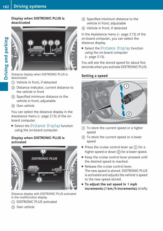
Display when DISTRONIC PLUS isdeactivated
Distance display when DISTRONIC PLUS isdeactivated: Vehicle in front, if detected; Distance indicator, current distance to
the vehicle in front= Specified minimum distance to the
vehicle in front; adjustable? Own vehicle
You can select the distance display in theAssistance menu (Y page 213) of the on-board computer.X Select the Distance DisplayDistance Display functionusing the on-board computer.
Display when DISTRONIC PLUS isactivated
Distance display with DISTRONIC PLUS activatedin the multifunction display: DISTRONIC PLUS activated; Own vehicle
= Specified minimum distance to thevehicle in front; adjustable
? Vehicle in front, if detected
In the Assistance menu (Y page 213) of theon-board computer, you can select thedistance display.X Select the Distance DisplayDistance Display functionusing the on-board computer(Y page 213).
You will see the stored speed for about fivesecondswhen you activateDISTRONICPLUS.
Setting a speed
: To store the current speed or a higherspeed
; To store the current speed or a lowerspeed
X Press the cruise control lever up: for ahigher speed or down; for a lower speed.
X Keep the cruise control lever pressed untilthe desired speed is reached.
X Release the cruise control lever.The new speed is stored. DISTRONIC PLUSis activated and adjusts the vehicle's speedto the new speed stored.
X To adjust the set speed in 1 mphincrements (1 km/h increments): briefly
182 Driving systemsDrivingandparking
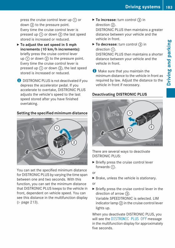
press the cruise control lever up: ordown; to the pressure point.Every time the cruise control lever ispressed up: or down; the last speedstored is increased or reduced.
X To adjust the set speed in 5 mphincrements (10 km/h increments):briefly press the cruise control leverup: or down; to the pressure point.Every time the cruise control lever ispressed up: or down;, the last speedstored is increased or reduced.
i DISTRONIC PLUS is not deactivated if youdepress the accelerator pedal. If youaccelerate to overtake, DISTRONIC PLUSadjusts the vehicle's speed to the lastspeed stored after you have finishedovertaking.
Setting the specifiedminimumdistance
You can set the specified minimum distancefor DISTRONIC PLUS by varying the time spanbetween one and two seconds. With thisfunction, you can set the minimum distancethat DISTRONIC PLUS keeps to the vehicle infront, dependent on vehicle speed. You cansee this distance in the multifunction display(Y page 213).
X To increase: turn control= indirection;.DISTRONIC PLUS then maintains a greaterdistance between your vehicle and thevehicle in front.
X To decrease: turn control= indirection:.DISTRONIC PLUS then maintains a shorterdistance between your vehicle and thevehicle in front.
i Make sure that you maintain theminimum distance to the vehicle in front asrequired by law. Adjust the distance to thevehicle in front if necessary.
Deactivating DISTRONIC PLUS
There are several ways to deactivateDISTRONIC PLUS:X Briefly press the cruise control leverforwards:.
orX Brake, unless the vehicle is stationary.orX Briefly press the cruise control lever in thedirection of arrow=.Variable SPEEDTRONIC is selected. LIMindicator lamp; in the cruise control leverlights up.
When you deactivate DISTRONIC PLUS, youwill see the DISTRONIC PLUS OffDISTRONIC PLUS Off messagein the multifunction display for approximatelyfive seconds.
Driving systems 183
Drivingandparking
Z
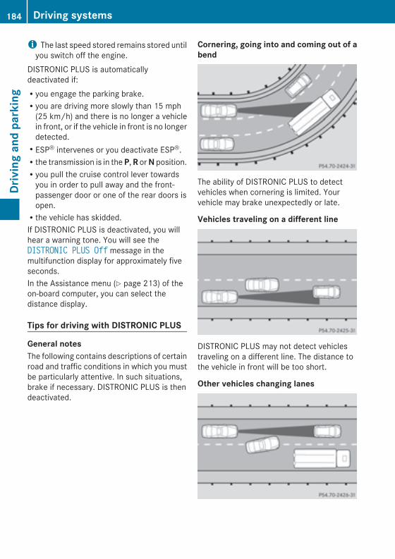
i The last speed stored remains stored untilyou switch off the engine.
DISTRONIC PLUS is automaticallydeactivated if:Ryou engage the parking brake.Ryou are driving more slowly than 15 mph(25 km/h) and there is no longer a vehiclein front, or if the vehicle in front is no longerdetected.RESP® intervenes or you deactivate ESP®.Rthe transmission is in theP,R orN position.Ryou pull the cruise control lever towardsyou in order to pull away and the front-passenger door or one of the rear doors isopen.Rthe vehicle has skidded.If DISTRONIC PLUS is deactivated, you willhear a warning tone. You will see theDISTRONIC PLUS OffDISTRONIC PLUS Off message in themultifunction display for approximately fiveseconds.In the Assistance menu (Y page 213) of theon-board computer, you can select thedistance display.
Tips for driving with DISTRONIC PLUS
General notesThe following contains descriptions of certainroad and traffic conditions in which you mustbe particularly attentive. In such situations,brake if necessary. DISTRONIC PLUS is thendeactivated.
Cornering, going into and coming out of abend
The ability of DISTRONIC PLUS to detectvehicles when cornering is limited. Yourvehicle may brake unexpectedly or late.
Vehicles traveling on a different line
DISTRONIC PLUS may not detect vehiclestraveling on a different line. The distance tothe vehicle in front will be too short.
Other vehicles changing lanes
184 Driving systemsDrivingandparking
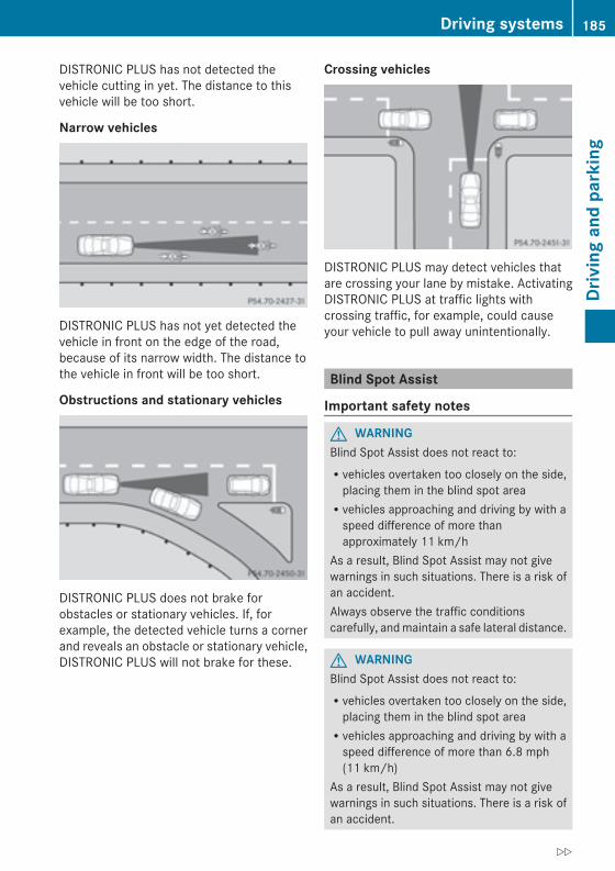
DISTRONIC PLUS has not detected thevehicle cutting in yet. The distance to thisvehicle will be too short.
Narrow vehicles
DISTRONIC PLUS has not yet detected thevehicle in front on the edge of the road,because of its narrow width. The distance tothe vehicle in front will be too short.
Obstructions and stationary vehicles
DISTRONIC PLUS does not brake forobstacles or stationary vehicles. If, forexample, the detected vehicle turns a cornerand reveals an obstacle or stationary vehicle,DISTRONIC PLUS will not brake for these.
Crossing vehicles
DISTRONIC PLUS may detect vehicles thatare crossing your lane by mistake. ActivatingDISTRONIC PLUS at traffic lights withcrossing traffic, for example, could causeyour vehicle to pull away unintentionally.
Blind Spot Assist
Important safety notes
G WARNINGBlind Spot Assist does not react to:Rvehicles overtaken too closely on the side,placing them in the blind spot areaRvehicles approaching and driving by with aspeed difference of more thanapproximately 11 km/h
As a result, Blind Spot Assist may not givewarnings in such situations. There is a risk ofan accident.Always observe the traffic conditionscarefully, andmaintain a safe lateral distance.
G WARNINGBlind Spot Assist does not react to:Rvehicles overtaken too closely on the side,placing them in the blind spot areaRvehicles approaching and driving by with aspeed difference of more than 6.8 mph(11 km/h)
As a result, Blind Spot Assist may not givewarnings in such situations. There is a risk ofan accident.
Driving systems 185
Drivingandparking
Z
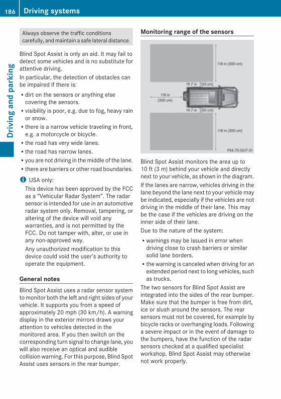
Always observe the traffic conditionscarefully, andmaintain a safe lateral distance.
Blind Spot Assist is only an aid. It may fail todetect some vehicles and is no substitute forattentive driving.In particular, the detection of obstacles canbe impaired if there is:Rdirt on the sensors or anything elsecovering the sensors.Rvisibility is poor, e.g. due to fog, heavy rainor snow.Rthere is a narrow vehicle traveling in front,e.g. a motorcycle or bicycle.Rthe road has very wide lanes.Rthe road has narrow lanes.Ryou are not driving in themiddle of the lane.Rthere are barriers or other road boundaries.
i USA only:This device has been approved by the FCCas a “Vehicular Radar System”. The radarsensor is intended for use in an automotiveradar system only. Removal, tampering, oraltering of the device will void anywarranties, and is not permitted by theFCC. Do not tamper with, alter, or use inany non-approved way.Any unauthorized modification to thisdevice could void the user’s authority tooperate the equipment.
General notesBlind Spot Assist uses a radar sensor systemtomonitor both the left and right sides of yourvehicle. It supports you from a speed ofapproximately 20 mph (30 km/h). A warningdisplay in the exterior mirrors draws yourattention to vehicles detected in themonitored area. If you then switch on thecorresponding turn signal to change lane, youwill also receive an optical and audiblecollision warning. For this purpose, Blind SpotAssist uses sensors in the rear bumper.
Monitoring range of the sensors
Blind Spot Assist monitors the area up to10 ft (3 m) behind your vehicle and directlynext to your vehicle, as shown in the diagram.If the lanes are narrow, vehicles driving in thelane beyond the lane next to your vehicle maybe indicated, especially if the vehicles are notdriving in the middle of their lane. This maybe the case if the vehicles are driving on theinner side of their lane.Due to the nature of the system:Rwarnings may be issued in error whendriving close to crash barriers or similarsolid lane borders.Rthe warning is canceled when driving for anextended period next to long vehicles, suchas trucks.
The two sensors for Blind Spot Assist areintegrated into the sides of the rear bumper.Make sure that the bumper is free from dirt,ice or slush around the sensors. The rearsensors must not be covered, for example bybicycle racks or overhanging loads. Followinga severe impact or in the event of damage tothe bumpers, have the function of the radarsensors checked at a qualified specialistworkshop. Blind Spot Assist may otherwisenot work properly.
186 Driving systemsDrivingandparking
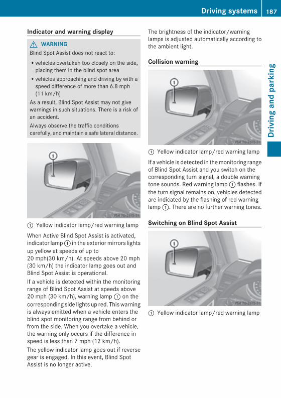
Indicator and warning display
G WARNINGBlind Spot Assist does not react to:Rvehicles overtaken too closely on the side,placing them in the blind spot areaRvehicles approaching and driving by with aspeed difference of more than 6.8 mph(11 km/h)
As a result, Blind Spot Assist may not givewarnings in such situations. There is a risk ofan accident.Always observe the traffic conditionscarefully, andmaintain a safe lateral distance.
: Yellow indicator lamp/red warning lamp
When Active Blind Spot Assist is activated,indicator lamp: in the exteriormirrors lightsup yellow at speeds of up to20 mph(30 km/h). At speeds above 20 mph(30 km/h) the indicator lamp goes out andBlind Spot Assist is operational.If a vehicle is detected within the monitoringrange of Blind Spot Assist at speeds above20 mph (30 km/h), warning lamp: on thecorresponding side lights up red. Thiswarningis always emitted when a vehicle enters theblind spot monitoring range from behind orfrom the side. When you overtake a vehicle,the warning only occurs if the difference inspeed is less than 7 mph (12 km/h).The yellow indicator lamp goes out if reversegear is engaged. In this event, Blind SpotAssist is no longer active.
The brightness of the indicator/warninglamps is adjusted automatically according tothe ambient light.
Collision warning
: Yellow indicator lamp/red warning lamp
If a vehicle is detected in themonitoring rangeof Blind Spot Assist and you switch on thecorresponding turn signal, a double warningtone sounds. Red warning lamp: flashes. Ifthe turn signal remains on, vehicles detectedare indicated by the flashing of red warninglamp:. There are no further warning tones.
Switching on Blind Spot Assist
: Yellow indicator lamp/red warning lamp
Driving systems 187
Drivingandparking
Z
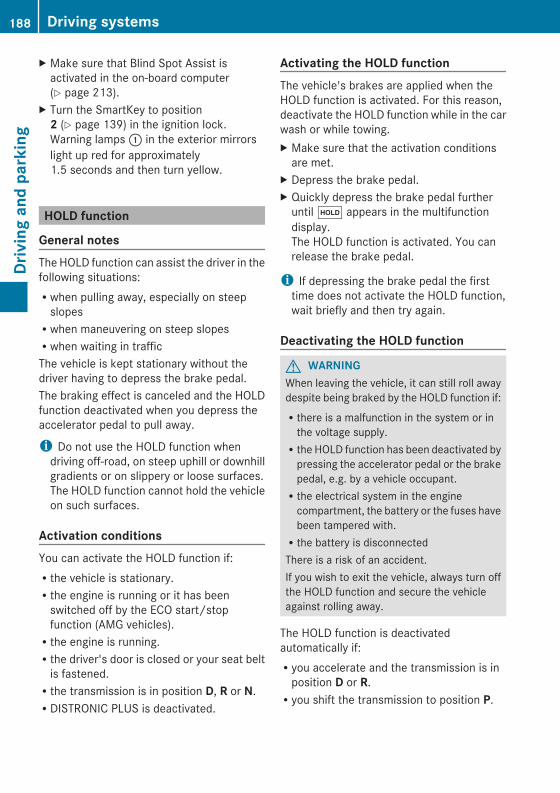
X Make sure that Blind Spot Assist isactivated in the on-board computer(Y page 213).
X Turn the SmartKey to position2 (Y page 139) in the ignition lock.Warning lamps: in the exterior mirrorslight up red for approximately1.5 seconds and then turn yellow.
HOLD function
General notesThe HOLD function can assist the driver in thefollowing situations:Rwhen pulling away, especially on steepslopesRwhen maneuvering on steep slopesRwhen waiting in trafficThe vehicle is kept stationary without thedriver having to depress the brake pedal.The braking effect is canceled and the HOLDfunction deactivated when you depress theaccelerator pedal to pull away.
i Do not use the HOLD function whendriving off-road, on steep uphill or downhillgradients or on slippery or loose surfaces.The HOLD function cannot hold the vehicleon such surfaces.
Activation conditionsYou can activate the HOLD function if:Rthe vehicle is stationary.Rthe engine is running or it has beenswitched off by the ECO start/stopfunction (AMG vehicles).Rthe engine is running.Rthe driver's door is closed or your seat beltis fastened.Rthe transmission is in position D, R or N.RDISTRONIC PLUS is deactivated.
Activating the HOLD functionThe vehicle's brakes are applied when theHOLD function is activated. For this reason,deactivate the HOLD function while in the carwash or while towing.X Make sure that the activation conditionsare met.
X Depress the brake pedal.X Quickly depress the brake pedal furtheruntilë appears in the multifunctiondisplay.The HOLD function is activated. You canrelease the brake pedal.
i If depressing the brake pedal the firsttime does not activate the HOLD function,wait briefly and then try again.
Deactivating the HOLD function
G WARNINGWhen leaving the vehicle, it can still roll awaydespite being braked by the HOLD function if:Rthere is a malfunction in the system or inthe voltage supply.Rthe HOLD function has been deactivated bypressing the accelerator pedal or the brakepedal, e.g. by a vehicle occupant.Rthe electrical system in the enginecompartment, the battery or the fuses havebeen tampered with.Rthe battery is disconnectedThere is a risk of an accident.If you wish to exit the vehicle, always turn offthe HOLD function and secure the vehicleagainst rolling away.
The HOLD function is deactivatedautomatically if:Ryou accelerate and the transmission is inposition D or R.Ryou shift the transmission to position P.
188 Driving systemsDrivingandparking
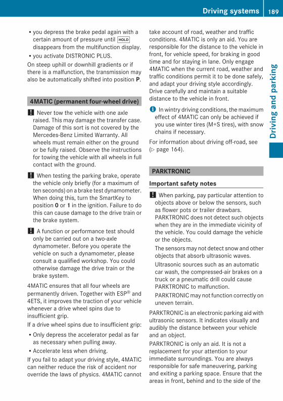
Ryou depress the brake pedal again with acertain amount of pressure untilëdisappears from the multifunction display.Ryou activate DISTRONIC PLUS.On steep uphill or downhill gradients or ifthere is a malfunction, the transmission mayalso be automatically shifted into position P.
4MATIC (permanent four-wheel drive)! Never tow the vehicle with one axleraised. This may damage the transfer case.Damage of this sort is not covered by theMercedes-Benz Limited Warranty. Allwheels must remain either on the groundor be fully raised. Observe the instructionsfor towing the vehicle with all wheels in fullcontact with the ground.
! When testing the parking brake, operatethe vehicle only briefly (for a maximum often seconds) on a brake test dynamometer.When doing this, turn the SmartKey toposition 0 or 1 in the ignition. Failure to dothis can cause damage to the drive train orthe brake system.
! A function or performance test shouldonly be carried out on a two-axledynamometer. Before you operate thevehicle on such a dynamometer, pleaseconsult a qualified workshop. You couldotherwise damage the drive train or thebrake system.
4MATIC ensures that all four wheels arepermanently driven. Together with ESP® and4ETS, it improves the traction of your vehiclewhenever a drive wheel spins due toinsufficient grip.If a drive wheel spins due to insufficient grip:ROnly depress the accelerator pedal as faras necessary when pulling away.RAccelerate less when driving.If you fail to adapt your driving style, 4MATICcan neither reduce the risk of accident noroverride the laws of physics. 4MATIC cannot
take account of road, weather and trafficconditions. 4MATIC is only an aid. You areresponsible for the distance to the vehicle infront, for vehicle speed, for braking in goodtime and for staying in lane. Only engage4MATIC when the current road, weather andtraffic conditions permit it to be done safely,and adapt your driving style accordingly.Drive carefully and maintain a suitabledistance to the vehicle in front.
i In wintry driving conditions, themaximumeffect of 4MATIC can only be achieved ifyou use winter tires (M+S tires), with snowchains if necessary.
For information about driving off-road, see(Y page 164).
PARKTRONIC
Important safety notes! When parking, pay particular attention toobjects above or below the sensors, suchas flower pots or trailer drawbars.PARKTRONIC does not detect such objectswhen they are in the immediate vicinity ofthe vehicle. You could damage the vehicleor the objects.The sensorsmay not detect snow and otherobjects that absorb ultrasonic waves.Ultrasonic sources such as an automaticcar wash, the compressed-air brakes on atruck or a pneumatic drill could causePARKTRONIC to malfunction.PARKTRONICmay not function correctly onuneven terrain.
PARKTRONIC is an electronic parking aid withultrasonic sensors. It indicates visually andaudibly the distance between your vehicleand an object.PARKTRONIC is only an aid. It is not areplacement for your attention to yourimmediate surroundings. You are alwaysresponsible for safe maneuvering, parkingand exiting a parking space. Ensure that theareas in front, behind and to the side of the
Driving systems 189
Drivingandparking
Z
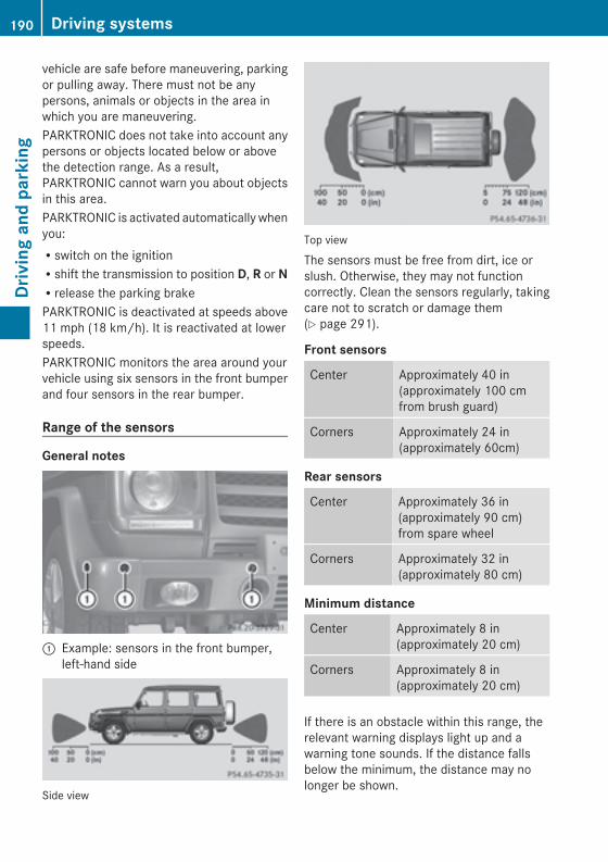
vehicle are safe before maneuvering, parkingor pulling away. There must not be anypersons, animals or objects in the area inwhich you are maneuvering.PARKTRONIC does not take into account anypersons or objects located below or abovethe detection range. As a result,PARKTRONIC cannot warn you about objectsin this area.PARKTRONIC is activated automatically whenyou:Rswitch on the ignitionRshift the transmission to position D, R or NRrelease the parking brakePARKTRONIC is deactivated at speeds above11 mph (18 km/h). It is reactivated at lowerspeeds.PARKTRONIC monitors the area around yourvehicle using six sensors in the front bumperand four sensors in the rear bumper.
Range of the sensors
General notes
: Example: sensors in the front bumper,left-hand side
Side view
Top view
The sensors must be free from dirt, ice orslush. Otherwise, they may not functioncorrectly. Clean the sensors regularly, takingcare not to scratch or damage them(Y page 291).
Front sensors
Center Approximately 40 in(approximately 100 cmfrom brush guard)
Corners Approximately 24 in(approximately 60cm)
Rear sensors
Center Approximately 36 in(approximately 90 cm)from spare wheel
Corners Approximately 32 in(approximately 80 cm)
Minimum distance
Center Approximately 8 in(approximately 20 cm)
Corners Approximately 8 in(approximately 20 cm)
If there is an obstacle within this range, therelevant warning displays light up and awarning tone sounds. If the distance fallsbelow the minimum, the distance may nolonger be shown.
190 Driving systemsDrivingandparking
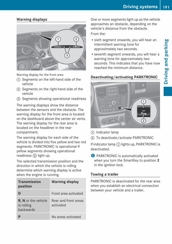
Warning displays
Warning display for the front area: Segments on the left-hand side of the
vehicle; Segments on the right-hand side of the
vehicle= Segments showing operational readiness
The warning displays show the distancebetween the sensors and the obstacle. Thewarning display for the front area is locatedon the dashboard above the center air vents.The warning display for the rear area islocated on the headliner in the rearcompartment.The warning display for each side of thevehicle is divided into five yellow and two redsegments. PARKTRONIC is operational ifyellow segments showing operationalreadiness= light up.The selected transmission position and thedirection in which the vehicle is rollingdetermine which warning display is activewhen the engine is running.
Transmissionposition
Warning display
D Front area activated
R, N or the vehicleis rollingbackwards
Rear and front areasactivated
P No areas activated
One or more segments light up as the vehicleapproaches an obstacle, depending on thevehicle's distance from the obstacle.From the:Rsixth segment onwards, you will hear anintermittent warning tone forapproximately two seconds.Rseventh segment onwards, you will hear awarning tone for approximately twoseconds. This indicates that you have nowreached the minimum distance.
Deactivating/activating PARKTRONIC
: Indicator lamp; To deactivate/activate PARKTRONIC
If indicator lamp: lights up, PARKTRONIC isdeactivated.
i PARKTRONIC is automatically activatedwhen you turn the SmartKey to position 2in the ignition lock.
Towing a trailerPARKTRONIC is deactivated for the rear areawhen you establish an electrical connectionbetween your vehicle and a trailer.
Driving systems 191
Drivingandparking
Z
Problems with PARKTRONIC
Problem Possible causes/consequences andMM Solutions
Only the red segmentsin the PARKTRONICwarning displays are lit.You also hear a warningtone for approximatelytwo seconds.PARKTRONIC isdeactivated after a fewseconds, and theindicator lamp in thePARKTRONIC buttonlights up.
PARKTRONIC has malfunctioned and has switched off.X If problems persist, have PARKTRONIC checked at a qualifiedspecialist workshop.
Only the red segmentsin the PARKTRONICwarning displays are lit.PARKTRONIC isdeactivated after a fewseconds.
The PARKTRONIC sensors are dirty or there is interference.X Clean the PARKTRONIC sensors (Y page 291).X Switch the ignition back on.
The problem may be caused by an external source of radio orultrasound waves.X See if PARKTRONIC functions in a different location.
Rear view camera
Important safety notesThe rear view camera is only an aid. It is nota replacement for your attention to yourimmediate surroundings. You are alwaysresponsible for safe maneuvering andparking. Whenmaneuvering or parking, makesure that there are no persons, animals orobjects in the area in which you aremaneuvering.Under the following circumstances, the rearview camera will not function, or will functionin a limited manner:Rthe rear door is openRin heavy rain, snow or fogRat night or in very dark placesRif the camera is exposed to very bright lightRif the area is lit by fluorescent light or LEDlighting (the display may flicker)
Rif there is a sudden change in temperature,e.g. when driving into a heated garage inwinterRif the camera lens is dirty or obstructedRif the rear of your vehicle is damaged. Inthis event, have the camera position andsetting checked at a qualified specialistworkshop Mercedes-Benz recommendsthat you use an authorized Mercedes-BenzCenter for this purpose
192 Driving systemsDrivingandparking
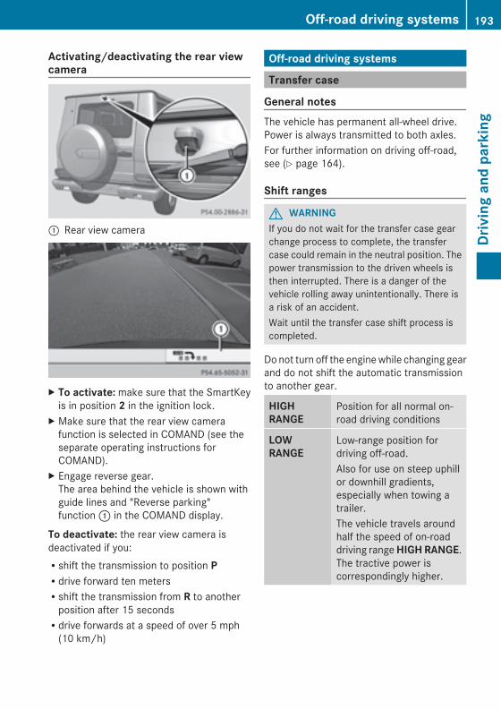
Activating/deactivating the rear viewcamera
: Rear view camera
X To activate:make sure that the SmartKeyis in position 2 in the ignition lock.
X Make sure that the rear view camerafunction is selected in COMAND (see theseparate operating instructions forCOMAND).
X Engage reverse gear.The area behind the vehicle is shown withguide lines and "Reverse parking"function: in the COMAND display.
To deactivate: the rear view camera isdeactivated if you:Rshift the transmission to position PRdrive forward ten metersRshift the transmission from R to anotherposition after 15 secondsRdrive forwards at a speed of over 5 mph(10 km/h)
Off-road driving systems
Transfer case
General notesThe vehicle has permanent all-wheel drive.Power is always transmitted to both axles.For further information on driving off-road,see (Y page 164).
Shift ranges
G WARNINGIf you do not wait for the transfer case gearchange process to complete, the transfercase could remain in the neutral position. Thepower transmission to the driven wheels isthen interrupted. There is a danger of thevehicle rolling away unintentionally. There isa risk of an accident.Wait until the transfer case shift process iscompleted.
Donot turn off the enginewhile changing gearand do not shift the automatic transmissionto another gear.
HIGHRANGE
Position for all normal on-road driving conditions
LOWRANGE
Low-range position fordriving off-road.Also for use on steep uphillor downhill gradients,especially when towing atrailer.The vehicle travels aroundhalf the speed of on-roaddriving rangeHIGHRANGE.The tractive power iscorrespondingly higher.
Off-road driving systems 193
Drivingandparking
Z
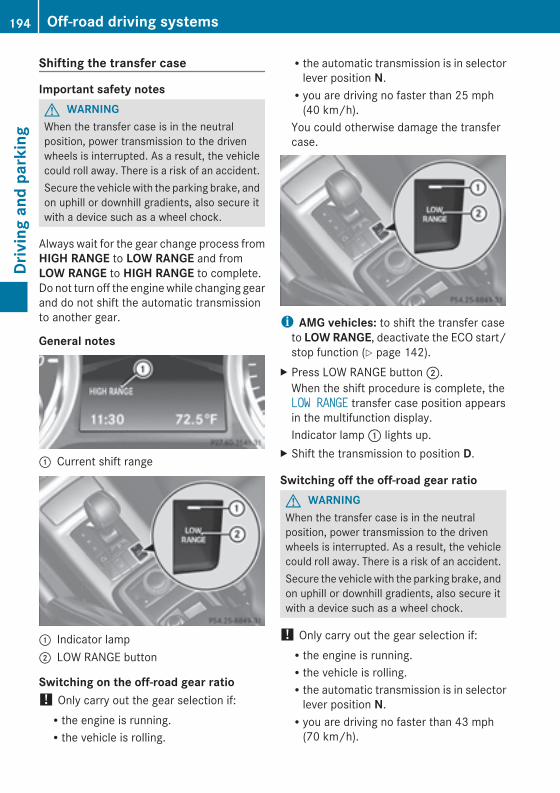
Shifting the transfer case
Important safety notesG WARNINGWhen the transfer case is in the neutralposition, power transmission to the drivenwheels is interrupted. As a result, the vehiclecould roll away. There is a risk of an accident.Secure the vehiclewith the parking brake, andon uphill or downhill gradients, also secure itwith a device such as a wheel chock.
Always wait for the gear change process fromHIGH RANGE to LOW RANGE and fromLOW RANGE to HIGH RANGE to complete.Do not turn off the enginewhile changing gearand do not shift the automatic transmissionto another gear.
General notes
: Current shift range
: Indicator lamp; LOW RANGE button
Switching on the off-road gear ratio! Only carry out the gear selection if:Rthe engine is running.Rthe vehicle is rolling.
Rthe automatic transmission is in selectorlever position N.Ryou are driving no faster than 25 mph(40 km/h).
You could otherwise damage the transfercase.
i AMG vehicles: to shift the transfer caseto LOWRANGE, deactivate the ECO start/stop function (Y page 142).
X Press LOW RANGE button;.When the shift procedure is complete, theLOW RANGELOW RANGE transfer case position appearsin the multifunction display.Indicator lamp: lights up.
X Shift the transmission to position D.
Switching off the off-road gear ratioG WARNINGWhen the transfer case is in the neutralposition, power transmission to the drivenwheels is interrupted. As a result, the vehiclecould roll away. There is a risk of an accident.Secure the vehiclewith the parking brake, andon uphill or downhill gradients, also secure itwith a device such as a wheel chock.
! Only carry out the gear selection if:Rthe engine is running.Rthe vehicle is rolling.Rthe automatic transmission is in selectorlever position N.Ryou are driving no faster than 43 mph(70 km/h).
194 Off-road driving systemsDrivingandparking
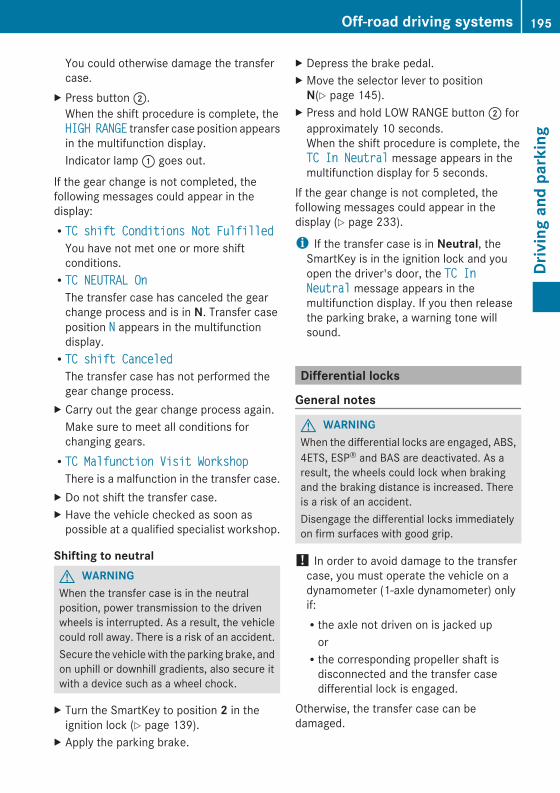
You could otherwise damage the transfercase.
X Press button;.When the shift procedure is complete, theHIGHHIGH RANGERANGE transfer case position appearsin the multifunction display.Indicator lamp: goes out.
If the gear change is not completed, thefollowing messages could appear in thedisplay:RTC shift Conditions Not FulfilledTC shift Conditions Not FulfilledYou have not met one or more shiftconditions.RTC NEUTRAL OnTC NEUTRAL OnThe transfer case has canceled the gearchange process and is in N. Transfer caseposition NN appears in the multifunctiondisplay.RTC shift CanceledTC shift CanceledThe transfer case has not performed thegear change process.
X Carry out the gear change process again.Make sure to meet all conditions forchanging gears.RTC Malfunction Visit WorkshopTC Malfunction Visit WorkshopThere is a malfunction in the transfer case.
X Do not shift the transfer case.X Have the vehicle checked as soon aspossible at a qualified specialist workshop.
Shifting to neutralG WARNINGWhen the transfer case is in the neutralposition, power transmission to the drivenwheels is interrupted. As a result, the vehiclecould roll away. There is a risk of an accident.Secure the vehiclewith the parking brake, andon uphill or downhill gradients, also secure itwith a device such as a wheel chock.
X Turn the SmartKey to position 2 in theignition lock (Y page 139).
X Apply the parking brake.
X Depress the brake pedal.X Move the selector lever to positionN(Y page 145).
X Press and hold LOW RANGE button; forapproximately 10 seconds.When the shift procedure is complete, theTC In NeutralTC In Neutral message appears in themultifunction display for 5 seconds.
If the gear change is not completed, thefollowing messages could appear in thedisplay (Y page 233).
i If the transfer case is in Neutral, theSmartKey is in the ignition lock and youopen the driver's door, the TC InTC InNeutralNeutral message appears in themultifunction display. If you then releasethe parking brake, a warning tone willsound.
Differential locks
General notes
G WARNINGWhen the differential locks are engaged, ABS,4ETS, ESP® and BAS are deactivated. As aresult, the wheels could lock when brakingand the braking distance is increased. Thereis a risk of an accident.Disengage the differential locks immediatelyon firm surfaces with good grip.
! In order to avoid damage to the transfercase, you must operate the vehicle on adynamometer (1-axle dynamometer) onlyif:Rthe axle not driven on is jacked uporRthe corresponding propeller shaft isdisconnected and the transfer casedifferential lock is engaged.
Otherwise, the transfer case can bedamaged.
Off-road driving systems 195
Drivingandparking
Z
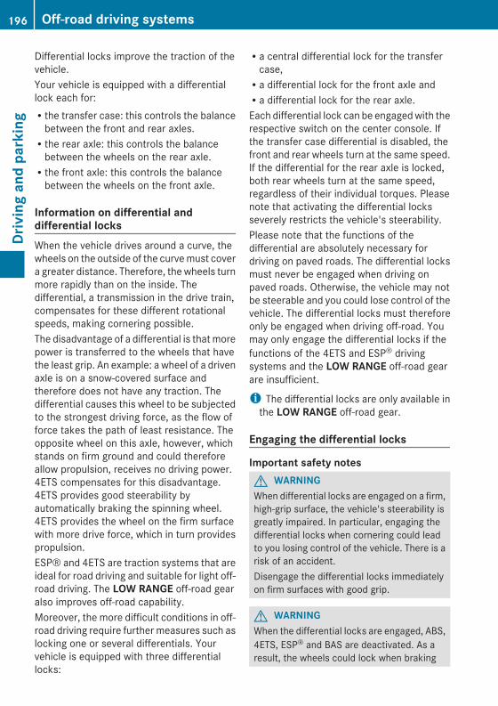
Differential locks improve the traction of thevehicle.Your vehicle is equipped with a differentiallock each for:Rthe transfer case: this controls the balancebetween the front and rear axles.Rthe rear axle: this controls the balancebetween the wheels on the rear axle.Rthe front axle: this controls the balancebetween the wheels on the front axle.
Information on differential anddifferential locksWhen the vehicle drives around a curve, thewheels on the outside of the curvemust covera greater distance. Therefore, the wheels turnmore rapidly than on the inside. Thedifferential, a transmission in the drive train,compensates for these different rotationalspeeds, making cornering possible.The disadvantage of a differential is thatmorepower is transferred to the wheels that havethe least grip. An example: a wheel of a drivenaxle is on a snow-covered surface andtherefore does not have any traction. Thedifferential causes this wheel to be subjectedto the strongest driving force, as the flow offorce takes the path of least resistance. Theopposite wheel on this axle, however, whichstands on firm ground and could thereforeallow propulsion, receives no driving power.4ETS compensates for this disadvantage.4ETS provides good steerability byautomatically braking the spinning wheel.4ETS provides the wheel on the firm surfacewith more drive force, which in turn providespropulsion.ESP® and 4ETS are traction systems that areideal for road driving and suitable for light off-road driving. The LOW RANGE off-road gearalso improves off-road capability.Moreover, the more difficult conditions in off-road driving require further measures such aslocking one or several differentials. Yourvehicle is equipped with three differentiallocks:
Ra central differential lock for the transfercase,Ra differential lock for the front axle andRa differential lock for the rear axle.Each differential lock can be engagedwith therespective switch on the center console. Ifthe transfer case differential is disabled, thefront and rear wheels turn at the same speed.If the differential for the rear axle is locked,both rear wheels turn at the same speed,regardless of their individual torques. Pleasenote that activating the differential locksseverely restricts the vehicle's steerability.Please note that the functions of thedifferential are absolutely necessary fordriving on paved roads. The differential locksmust never be engaged when driving onpaved roads. Otherwise, the vehicle may notbe steerable and you could lose control of thevehicle. The differential locks must thereforeonly be engaged when driving off-road. Youmay only engage the differential locks if thefunctions of the 4ETS and ESP® drivingsystems and the LOW RANGE off-road gearare insufficient.
i The differential locks are only available inthe LOW RANGE off-road gear.
Engaging the differential locks
Important safety notesG WARNINGWhen differential locks are engaged on a firm,high-grip surface, the vehicle's steerability isgreatly impaired. In particular, engaging thedifferential locks when cornering could leadto you losing control of the vehicle. There is arisk of an accident.Disengage the differential locks immediatelyon firm surfaces with good grip.
G WARNINGWhen the differential locks are engaged, ABS,4ETS, ESP® and BAS are deactivated. As aresult, the wheels could lock when braking
196 Off-road driving systemsDrivingandparking
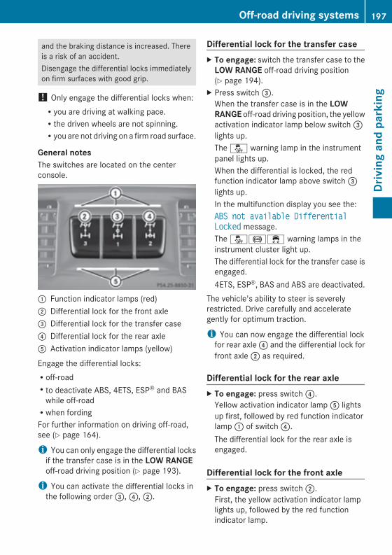
and the braking distance is increased. Thereis a risk of an accident.Disengage the differential locks immediatelyon firm surfaces with good grip.
! Only engage the differential locks when:Ryou are driving at walking pace.Rthe driven wheels are not spinning.Ryou are not driving on a firm road surface.
General notesThe switches are located on the centerconsole.
: Function indicator lamps (red); Differential lock for the front axle= Differential lock for the transfer case? Differential lock for the rear axleA Activation indicator lamps (yellow)
Engage the differential locks:Roff-roadRto deactivate ABS, 4ETS, ESP® and BASwhile off-roadRwhen fordingFor further information on driving off-road,see (Y page 164).
i You can only engage the differential locksif the transfer case is in the LOW RANGEoff-road driving position (Y page 193).
i You can activate the differential locks inthe following order=,?,;.
Differential lock for the transfer caseX To engage: switch the transfer case to theLOW RANGE off-road driving position(Y page 194).
X Press switch=.When the transfer case is in the LOWRANGE off-road driving position, the yellowactivation indicator lamp below switch=lights up.The å warning lamp in the instrumentpanel lights up.When the differential is locked, the redfunction indicator lamp above switch=lights up.In the multifunction display you see the:ABS not available DifferentialABS not available DifferentialLockedLocked message.The å!÷ warning lamps in theinstrument cluster light up.The differential lock for the transfer case isengaged.4ETS, ESP®, BAS and ABS are deactivated.
The vehicle's ability to steer is severelyrestricted. Drive carefully and accelerategently for optimum traction.
i You can now engage the differential lockfor rear axle? and the differential lock forfront axle; as required.
Differential lock for the rear axleX To engage: press switch?.Yellow activation indicator lampA lightsup first, followed by red function indicatorlamp: of switch?.The differential lock for the rear axle isengaged.
Differential lock for the front axleX To engage: press switch;.First, the yellow activation indicator lamplights up, followed by the red functionindicator lamp.
Off-road driving systems 197
Drivingandparking
Z
The differential lock for the front axle isengaged.
Disengaging the differential locksYou can disengage the differential locks in thefollowing order:;,?,=.X To simultaneously disengage alldifferential locks: press switch=.Yellow activation indicator lampsA andred function indicator lamps: go out.After approximately three seconds ofnormal driving, ABS, 4ETS, ESP® and BASare activated.The ABSABS notnot availableavailable DifferentialDifferentialLockedLocked message disappears in themultifunction display and the å, !and ÷ warning lamps in the instrumentcluster go out.
X Shift the transfer case to the HIGHRANGE on-road position (Y page 194).
i If red function indicator lamps: do notgo out after disengaging the differentiallocks, bring the vehicle to a standstill inaccordance with the traffic conditions.Then continue driving, as the load changecan release the differential locks.
Towing a trailer
Notes on towing a trailer
Important safety notes
G WARNINGIf you rest your foot on the brake pedal whiledriving, the braking system can overheat. Thisincreases the stopping distance and can evencause the braking system to fail. There is arisk of an accident.Never use the brake pedal as a footrest. Neverdepress the brake pedal and the acceleratorpedal at the same time.
G WARNINGWhen the vehicle/trailer combination beginsto lurch, you could lose control of it. Thevehicle/trailer combination could evenrollover. There is a risk of an accident.On no account should you attempt tostraighten up the vehicle/trailer combinationby increasing the speed. Reduce vehiclespeed and do not countersteer. Apply thebrake as necessary.
G WARNINGIf you install a ball coupling other than the onedeliveredwith the vehicle, the trailer tow hitchand the rear axle may be overloaded. Thisapplies especially if the ball coupling inquestion is longer or angled differently. Thiscould seriously impair the drivingcharacteristics and the trailer can comeloose. There is a risk of an accident.Only install the ball coupling delivered withthe vehicle or a ball coupling that is designedto meet your trailer towing requirements. Donot modify the ball coupling or the trailer towhitch.
G WARNINGIf the ball coupling is not installed correctly ornot secured with the bolt provided and thecorresponding spring cotter, the trailer maycome loose. There is a risk of an accident.Always install and secure the ball coupling asdescribed. Before every journey, ensure thatthe ball coupling is secured with the bolt andthe corresponding spring cotter.
Please observe the manufacturer's operatinginstructions for the trailer coupling if adetachable trailer coupling is used.You will find the applicable permissiblevalues, which must not be exceeded, in thevehicle documents. You will find the valuesapproved by the manufacturer on the vehicleidentification plates and those for the towingvehicle in the "Technical data" section(Y page 342).
198 Towing a trailerDrivingandparking
Couple and uncouple the trailer carefully. Ifyou do not couple the trailer to the towingvehicle correctly, the trailer could becomedetached.Make sure that the following values are notexceeded:Rthe permissible trailer drawbar noseweightRthe permissible trailer loadRthe permissible rear axle load of the towingvehicleRthe maximum permissible gross vehicleweight of both the towing vehicle and thetrailer
When towing a trailer, your vehicle's handlingcharacteristics will be different in comparisonwith when driving without a trailer.The vehicle/trailer combination:Ris heavierRis restricted in its acceleration andgradient-climbing capabilityRhas an increased braking distanceRis affected more by strong crosswindsRdemands more sensitive steeringRhas a larger turning circleThis could impair the handlingcharacteristics.When towing a trailer, always adjust yourspeed to the current road and weatherconditions. Do not exceed the maximumpermissible speed for your vehicle/trailercombination.
General notesRDo not exceed the legally prescribedmaximum speed for vehicle/trailercombinations in the relevant country.This lowers the risk of an accident.ROnly install an approved trailer coupling onyour vehicle.Further information on availability and oninstallation is available from any authorizedMercedes-Benz Center.
RThe bumpers of your vehicle are notsuitable for installing detachable trailercouplings.RDo not install hired trailer couplings orother detachable trailer couplings on thebumpers of your vehicle.RIf you do not need the ball coupling, removethe ball coupling from the ball couplingrecess. This reduces the risk of damage tothe ball coupling.
i When towing a trailer, set the tirepressure on the rear axle of the towingvehicle for a maximum load; see the tirepressure table in the fuel filler flap(Y page 316).
Youwill find installation dimensions and loadsin the technical data (Y page 351).The maximum noseweight of the trailerdrawbar on the ball coupling for up to 3people is 562 lbs (255 kg). The maximumpermissible trailer drawbar noseweight formore than 3 persons and the maximum loadin the trunk can be found in the trailerdrawbar noseweight table (Y page 352).However, the actual noseweight must notexceed the value given on the trailer tow hitchor trailer identification plates. The lowestweight applies.
i When towing a trailer, set the tirepressure on the rear axle of the towingvehicle for a maximum load; see the tirepressure table in the fuel filler flap(Y page 316).
Please note that when towing a trailer,PARKTRONIC (Y page 189) and Blind SpotAssist (Y page 185) are only available withlimitations, or not at all.
i On vehicles without level control, theheight of the ball coupling will alteraccording to the load placed on the vehicle.If necessary, use a trailer with a height-adjustable drawbar.
Towing a trailer 199
Drivingandparking
Z
Driving tipsX On long and steep downhill gradients,select shift range 1, 2 or 3 (Y page 150) ingood time.i This also applies if you have activatedcruise control or SPEEDTRONIC.
X If necessary, shift the transfer case to LOWRANGE(Y page 194).This will use the braking effect of theengine, so that less braking will be requiredto maintain the speed. This relieves theload on the brake system and prevents thebrakes from overheating and wearing tooquickly. If you need additional braking,depress the brake pedal repeatedly ratherthan continuously.
The maximum permissible speed for vehicle/trailer combinations depends on the type oftrailer. Before beginning the journey, checkthe trailer's documents to see what themaximum permissible speed is. Observe thelegally prescribed maximum speed in therelevant country.For certain Mercedes-Benz vehicles, themaximum permissible rear axle load isincreased when towing a trailer. Refer to the"Technical data" section to find out whetherthis applies to your vehicle. If you utilize anyof the added maximum rear axle load whentowing a trailer, the vehicle/trailercombination may not exceed a maximumspeed of 60 mph (100 km/h) for reasonsconcerning the operating permit. This alsoapplies in countries in which the permissiblemaximum speed for vehicle/trailercombinations is above 60 mph (100 km/h).When towing a trailer, your vehicle's handlingcharacteristics will be different in comparisonto when driving without a trailer and it willconsume more fuel.On long and steep downhill gradients, youmust select shift range 1, 2 or 3 in good time.i This also applies if you have activatedcruise control or DISTRONIC PLUS.
This will use the braking effect of the engine,so that less braking will be required tomaintain the speed. This relieves the load onthe brake system and prevents the brakesfrom overheating and wearing too quickly. Ifyou need additional braking, depress thebrake pedal repeatedly rather thancontinuously.
Driving tipsIf the trailer swings from side to side:X Do not accelerate.X Do not counter-steer.X Brake if necessary.RMaintain a greater distance from thevehicle in front than when driving without atrailer.RAvoid braking abruptly. If possible, brakegently at first to allow the trailer to run on.Then, increase the braking force rapidly.RThe values given for gradient-climbingcapabilities from a standstill refer to sealevel. When driving in mountainous areas,note that the power output of the engine,and consequently the vehicle's gradient-climbing capability, decrease withincreasing altitude.
Trailer power supply! You can connect accessories with amaximum power consumption of 180 W tothe permanent power supply.You must not charge a trailer battery usingthe power supply.
The trailer socket of your vehicle is equippedat the factorywith a permanent power supply.The permanent power supply is supplied viatrailer socket pin 9.A qualified specialist workshop can providemore information about installing the trailerelectrics.
200 Towing a trailerDrivingandparking
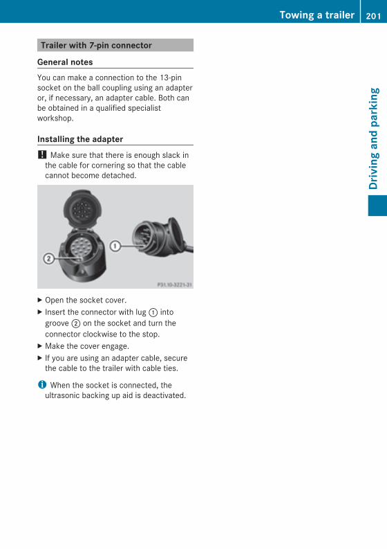
Trailer with 7-pin connector
General notesYou can make a connection to the 13-pinsocket on the ball coupling using an adapteror, if necessary, an adapter cable. Both canbe obtained in a qualified specialistworkshop.
Installing the adapter! Make sure that there is enough slack inthe cable for cornering so that the cablecannot become detached.
X Open the socket cover.X Insert the connector with lug: intogroove; on the socket and turn theconnector clockwise to the stop.
X Make the cover engage.X If you are using an adapter cable, securethe cable to the trailer with cable ties.
i When the socket is connected, theultrasonic backing up aid is deactivated.
Towing a trailer 201
Drivingandparking
Z

202

Useful information ............................ 204Important safety notes .................... 204Displays and operation .................... 205Menus and submenus ...................... 208Display messages ............................. 220Warning and indicator lamps in theinstrument cluster ............................ 242
203
On-board
computerand
displays
Useful information
i This Operator's Manual describes allmodels and all standard and optionalequipment of your vehicle available at thetime of publication of the Operator'sManual. Country-specific differences arepossible. Please note that your vehicle maynot be equipped with all featuresdescribed. This also applies to safety-related systems and functions.
i Read the information on qualifiedspecialist workshops: (Y page 24).
Important safety notes
G WARNINGThe driver's concentration must always bedirected primarily at road traffic.For your safety and the safety of others,selecting features through the multifunctionsteering wheel should only be done by thedriver when traffic and road conditions permitit to be done safely.Bear in mind that at a speed of only 30 mph(approximately 50 km/h), the vehicle coversa distance of 44 feet (approximately 14m) persecond.
G WARNINGNo messages will be displayed if either theinstrument cluster or the multifunctiondisplay is inoperative.As a result, you will not be able to seeinformation about your driving conditions,such asRspeedRoutside temperatureRwarning/indicator lampsRmalfunction/warning messagesRfailure of any systemsDriving characteristics may be impaired.
If youmust continue to drive, do sowith addedcaution. Contact an authorized Mercedes-Benz Center as soon as possible.
G WARNINGMalfunction and warning messages are onlydisplayed for certain systems and areintentionally not very detailed. Themalfunction and warning messages aresimply a reminder with respect to theoperation of certain systems. They do notreplace the owner's and/or driver'sresponsibility to maintain the vehicle'soperating safety. Have all requiredmaintenance services and safety checksperformed on the vehicle. Bring the vehicle toan authorized Mercedes-Benz Center toaddress the malfunction and warningmessages.
G WARNINGAll categories of messages contain importantinformation which should be taken note ofand, where a malfunction is indicated,addressed as soon as possible at anauthorized Mercedes-Benz Center.Failure to repair the condition noted maycause damage not covered by the Mercedes-Benz Limited Warranty, or result in propertydamage or personal injury.
For an illustration of the instrument cluster,see (Y page 205).
204 Important safety notesOn
-board
computerand
displays
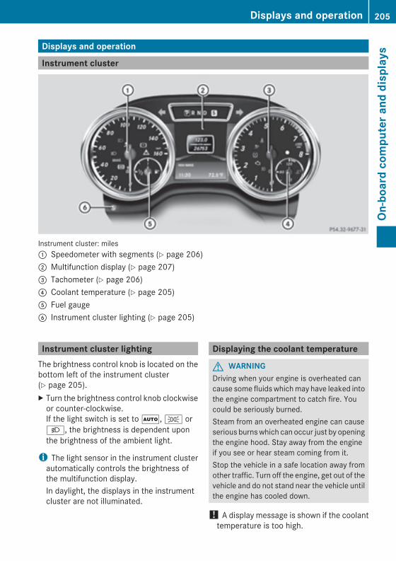
Displays and operation
Instrument cluster
Instrument cluster: miles: Speedometer with segments (Y page 206); Multifunction display (Y page 207)= Tachometer (Y page 206)? Coolant temperature (Y page 205)A Fuel gaugeB Instrument cluster lighting (Y page 205)
Instrument cluster lightingThe brightness control knob is located on thebottom left of the instrument cluster(Y page 205).X Turn the brightness control knob clockwiseor counter-clockwise.If the light switch is set toÃ, T orL, the brightness is dependent uponthe brightness of the ambient light.
i The light sensor in the instrument clusterautomatically controls the brightness ofthe multifunction display.In daylight, the displays in the instrumentcluster are not illuminated.
Displaying the coolant temperature
G WARNINGDriving when your engine is overheated cancause some fluids whichmay have leaked intothe engine compartment to catch fire. Youcould be seriously burned.Steam from an overheated engine can causeserious burnswhich can occur just by openingthe engine hood. Stay away from the engineif you see or hear steam coming from it.Stop the vehicle in a safe location away fromother traffic. Turn off the engine, get out of thevehicle and do not stand near the vehicle untilthe engine has cooled down.
! A display message is shown if the coolanttemperature is too high.
Displays and operation 205
On-board
computerand
displays
Z
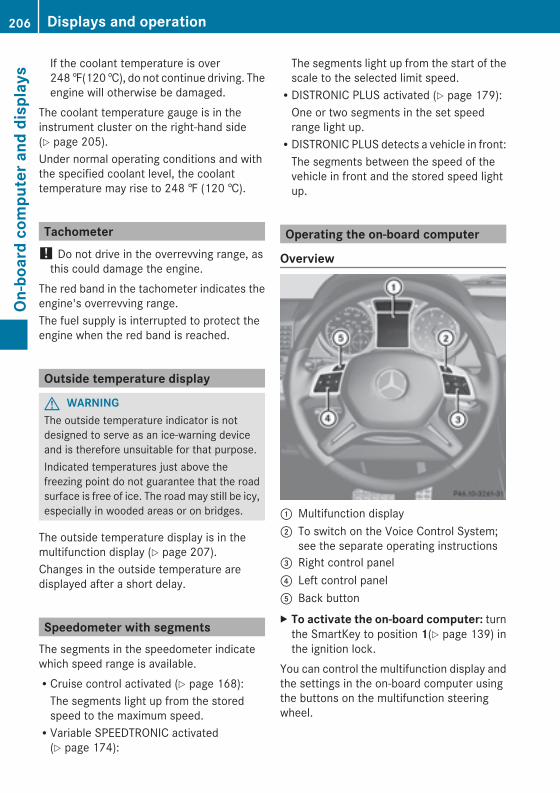
If the coolant temperature is over248‡(120†), do not continue driving. Theengine will otherwise be damaged.
The coolant temperature gauge is in theinstrument cluster on the right-hand side(Y page 205).Under normal operating conditions and withthe specified coolant level, the coolanttemperature may rise to 248 ‡ (120 †).
Tachometer! Do not drive in the overrevving range, asthis could damage the engine.
The red band in the tachometer indicates theengine's overrevving range.The fuel supply is interrupted to protect theengine when the red band is reached.
Outside temperature display
G WARNINGThe outside temperature indicator is notdesigned to serve as an ice-warning deviceand is therefore unsuitable for that purpose.Indicated temperatures just above thefreezing point do not guarantee that the roadsurface is free of ice. The roadmay still be icy,especially in wooded areas or on bridges.
The outside temperature display is in themultifunction display (Y page 207).Changes in the outside temperature aredisplayed after a short delay.
Speedometer with segmentsThe segments in the speedometer indicatewhich speed range is available.RCruise control activated (Y page 168):The segments light up from the storedspeed to the maximum speed.RVariable SPEEDTRONIC activated(Y page 174):
The segments light up from the start of thescale to the selected limit speed.RDISTRONIC PLUS activated (Y page 179):One or two segments in the set speedrange light up.RDISTRONIC PLUS detects a vehicle in front:The segments between the speed of thevehicle in front and the stored speed lightup.
Operating the on-board computer
Overview
: Multifunction display; To switch on the Voice Control System;
see the separate operating instructions= Right control panel? Left control panelA Back buttonX To activate the on-board computer: turnthe SmartKey to position 1(Y page 139) inthe ignition lock.
You can control the multifunction display andthe settings in the on-board computer usingthe buttons on the multifunction steeringwheel.
206 Displays and operationOn
-board
computerand
displays
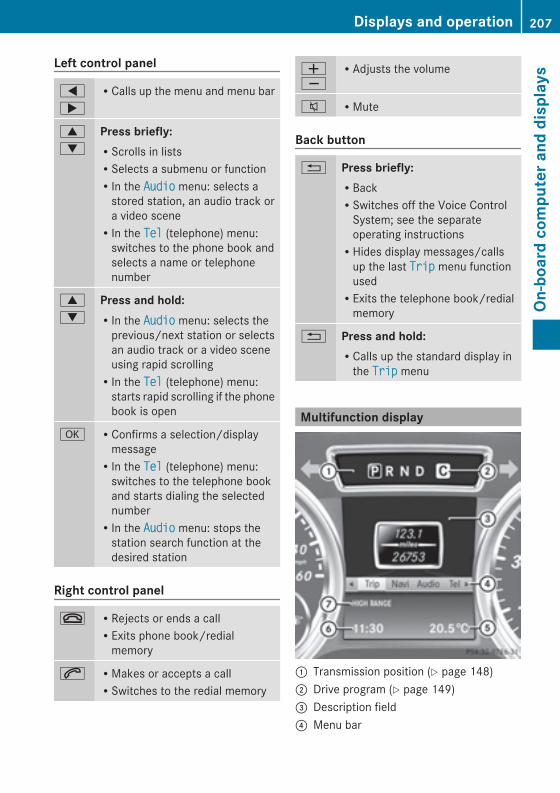
Left control panel
=
;
RCalls up the menu and menu bar
9
:
Press briefly:RScrolls in listsRSelects a submenu or functionRIn the AudioAudio menu: selects astored station, an audio track ora video sceneRIn the TelTel (telephone) menu:switches to the phone book andselects a name or telephonenumber
9
:
Press and hold:RIn the AudioAudio menu: selects theprevious/next station or selectsan audio track or a video sceneusing rapid scrollingRIn the TelTel (telephone) menu:starts rapid scrolling if the phonebook is open
a RConfirms a selection/displaymessageRIn the TelTel (telephone) menu:switches to the telephone bookand starts dialing the selectednumberRIn the AudioAudio menu: stops thestation search function at thedesired station
Right control panel
~ RRejects or ends a callRExits phone book/redialmemory
6 RMakes or accepts a callRSwitches to the redial memory
WX
RAdjusts the volume
8 RMute
Back button
% Press briefly:RBackRSwitches off the Voice ControlSystem; see the separateoperating instructionsRHides display messages/callsup the last TripTrip menu functionusedRExits the telephone book/redialmemory
% Press and hold:RCalls up the standard display inthe TripTrip menu
Multifunction display
: Transmission position (Y page 148); Drive program (Y page 149)= Description field? Menu bar
Displays and operation 207
On-board
computerand
displays
Z
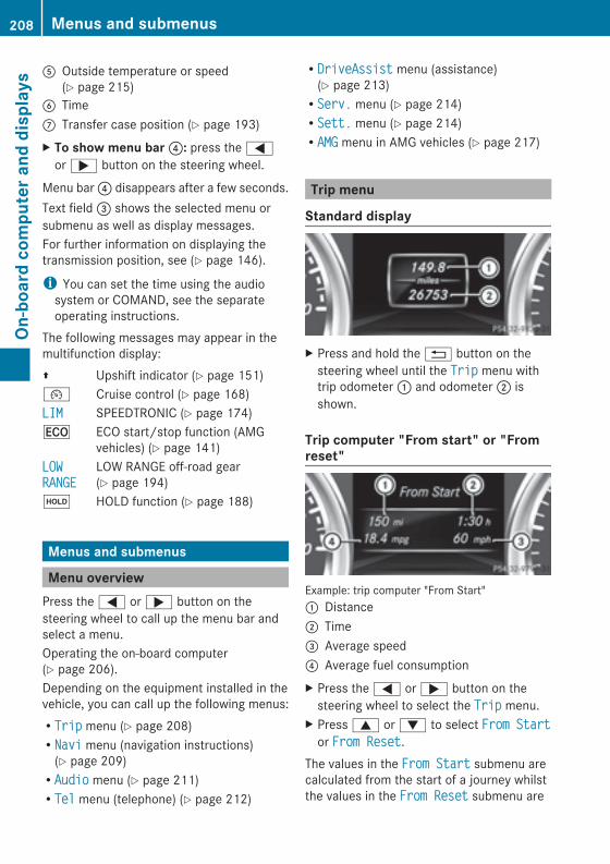
A Outside temperature or speed(Y page 215)
B TimeC Transfer case position (Y page 193)X To show menu bar?: press the=or; button on the steering wheel.
Menu bar? disappears after a few seconds.Text field= shows the selected menu orsubmenu as well as display messages.For further information on displaying thetransmission position, see (Y page 146).
i You can set the time using the audiosystem or COMAND, see the separateoperating instructions.
The following messages may appear in themultifunction display:Z Upshift indicator (Y page 151)¯ Cruise control (Y page 168)LIMLIM SPEEDTRONIC (Y page 174)¤ ECO start/stop function (AMG
vehicles) (Y page 141)LOWLOWRANGERANGE
LOW RANGE off-road gear(Y page 194)
ë HOLD function (Y page 188)
Menus and submenus
Menu overviewPress the= or; button on thesteering wheel to call up the menu bar andselect a menu.Operating the on-board computer(Y page 206).Depending on the equipment installed in thevehicle, you can call up the following menus:RTripTrip menu (Y page 208)RNaviNavi menu (navigation instructions)(Y page 209)RAudioAudio menu (Y page 211)RTelTel menu (telephone) (Y page 212)
RDriveAssistDriveAssist menu (assistance)(Y page 213)RServ.Serv. menu (Y page 214)RSett.Sett. menu (Y page 214)RAMGAMG menu in AMG vehicles (Y page 217)
Trip menu
Standard display
X Press and hold the% button on thesteering wheel until the TripTrip menu withtrip odometer: and odometer; isshown.
Trip computer "From start" or "Fromreset"
Example: trip computer "From Start": Distance; Time= Average speed? Average fuel consumptionX Press the= or; button on thesteering wheel to select the TripTrip menu.
X Press9 or: to select From StartFrom Startor From ResetFrom Reset.
The values in the From StartFrom Start submenu arecalculated from the start of a journey whilstthe values in the From ResetFrom Reset submenu are
208 Menus and submenusOn
-board
computerand
displays
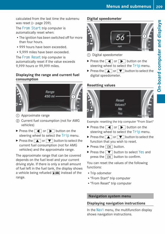
calculated from the last time the submenuwas reset (Y page 209).The From StartFrom Start trip computer isautomatically reset when:RThe ignition has been switched off for morethan four hours.R999 hours have been exceeded.R9,999 miles have been exceeded.The From ResetFrom Reset trip computer isautomatically reset if the value exceeds9,999 hours or 99,999 miles.
Displaying the range and current fuelconsumption
: Approximate range; Current fuel consumption (not for AMG
vehicles)X Press the= or; button on thesteering wheel to select the TripTrip menu.
X Press the9 or: button to select thecurrent fuel consumption (not for AMGvehicles) and the approximate range.
The approximate range that can be covereddepends on the fuel level and your currentdriving style. If there is only a small amountof fuel left in the fuel tank, the display showsa vehicle being refueledC instead of therange.
Digital speedometer
: Digital speedometerX Press the= or; button on thesteering wheel to select the TripTrip menu.
X Press the9 or: button to select thedigital speedometer.
Resetting values
Example: resetting the trip computer "From Start"X Press the= or; button on thesteering wheel to select the TripTrip menu.
X Press the9 or: button to select thefunction that you wish to reset.
X Press thea button.X Press the: button to select YesYes andpress thea button to confirm.
You can reset the values of the followingfunctions:RTrip odometerR"From Start" trip computerR"From Reset" trip computer
Navigation system menu
Displaying navigation instructionsIn the NaviNavi menu, the multifunction displayshows navigation instructions.
Menus and submenus 209
On-board
computerand
displays
Z
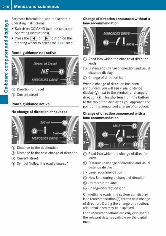
For more information, see the separateoperating instructions.X Switch on COMAND (see the separateoperating instructions).
X Press the= or; button on thesteering wheel to select the NaviNavi menu.
Route guidance not active
: Direction of travel; Current street
Route guidance active
No change of direction announced
: Distance to the destination; Distance to the next change of direction= Current street? Symbol "follow the road's course"
Change of direction announced without alane recommendation
: Road into which the change of directionleads
; Distance to change of direction and visualdistance display
= Change-of-direction icon
When a change of direction has beenannounced, you will see visual distancedisplay; next to the symbol for change ofdirection=. This shortens from the bottomto the top of the display as you approach thepoint of the announced change of direction.
Change of direction announced with alane recommendation
: Road into which the change of directionleads
; Distance to change of direction and visualdistance display
= Lane recommendation? New lane during a change of directionA Uninterrupted laneB Change-of-direction icon
On multilane roads, the system can displaylane recommendation= for the next changeof direction. During the change of direction,additional lanes may be displayed.Lane recommendations are only displayed ifthe relevant data is available on the digitalmap.
210 Menus and submenusOn
-board
computerand
displays
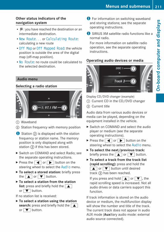
Other status indicators of thenavigation systemRO: you have reached the destination or anintermediate destination.RNew Route...New Route... or Calculating RouteCalculating Route:calculating a new routeROff MapOff Map or OffOff MappedMapped RoadRoad: the vehicleposition is outside the area of the digitalmap (off-map position).RNo RouteNo Route: no route could be calculated tothe selected destination.
Audio menu
Selecting a radio station
: Waveband; Station frequency with memory position
i Station; is displayed with the stationfrequency or station name. The memoryposition is only displayed along withstation; if this has been stored.
X Switch on COMAND and select Radio; seethe separate operating instructions.
X Press the= or; button on thesteering wheel to select the AudioAudio menu.
X To select a stored station: briefly pressthe9 or: button.
X To select a station from the stationlist: press and briefly hold the9or: button.
If no station list is received:X To select a station using the stationsearch: press and briefly hold the9or: button.
i For information on switching wavebandand storing stations; see the separateoperating instructions.
i SIRIUS XM satellite radio functions like anormal radio.For more information on satellite radiooperation, see the separate operatinginstructions.
Operating audio devices or media
Display CD/DVD changer (example): Current CD in the CD/DVD changer; Current title
Audio data from various audio devices ormedia can be played, depending on theequipment installed in the vehicle.X Switch on COMAND and select the audioplayer or medium (see the separateoperating instructions).
X Press the= or; button on thesteering wheel to select the AudioAudio menu.
X To select the next/previous track:briefly press the9 or: button.
X To select a track from the track list(rapid scrolling): press and hold the9 or: button until desiredtrack; has been reached.If you press and hold9 or:, therapid scrolling speed is increased. Not allaudio drives or data carriers support thisfunction.
If track information is stored on the audiodevice or medium, the multifunction displaywill show the number and title of the track.The current track does not appear in audioAUX mode (Auxiliary audio mode: externalaudio source connected).
Menus and submenus 211
On-board
computerand
displays
Z
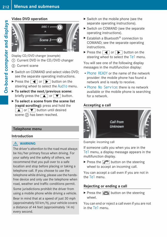
Video DVD operation
Display CD/DVD changer (example): Current DVD in the CD/DVD changer; Current sceneX Switch on COMAND and select video DVD;see the separate operating instructions.
X Press the= or; button on thesteering wheel to select the AudioAudio menu.
X To select the next/previous scene:briefly press the9 or: button.
X To select a scene from the scene list(rapid scrolling): press and hold the9 or: button until desiredscene; has been reached.
Telephone menu
Introduction
G WARNINGThe driver's attention to the roadmust alwaysbe his/her primary focus when driving. Foryour safety and the safety of others, werecommend that you pull over to a safelocation and stop before placing or taking atelephone call. If you choose to use thetelephonewhile driving, please use the hands-free device and only use the telephone whenroad, weather and traffic conditions permit.Some jurisdictions prohibit the driver fromusing a mobile phone while driving a vehicle.Bear in mind that at a speed of just 30 mph(approximately 50 km/h), your vehicle coversa distance of 44 feet (approximately 14 m)every second.
X Switch on the mobile phone (see theseparate operating instructions).
X Switch on COMAND (see the separateoperating instructions).
X Establish a Bluetooth® connection toCOMAND; see the separate operatinginstructions.
X Press the= or; button on thesteering wheel to select the TelTel menu.
You will see one of the following displaymessages in the multifunction display:RPhone READYPhone READY or the name of the networkprovider: the mobile phone has found anetwork and is ready to receive.RPhone No ServicePhone No Service: there is no networkavailable or the mobile phone is searchingfor a network.
Accepting a call
Example: incoming call
If someone calls you when you are in theTelTel menu, a display message appears in themultifunction display.X Press the6 button on the steeringwheel to accept an incoming call.
You can accept a call even if you are not inthe TelTel menu.Rejecting or ending a callX Press the~ button on the steeringwheel.
You can end or reject a call even if you are notin the TelTel menu.
212 Menus and submenusOn
-board
computera
nddisplays
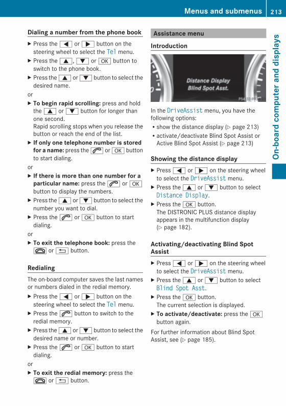
Dialing a number from the phone bookX Press the= or; button on thesteering wheel to select the TelTel menu.
X Press the9,: ora button toswitch to the phone book.
X Press the9 or: button to select thedesired name.
orX To begin rapid scrolling: press and holdthe9 or: button for longer thanone second.Rapid scrolling stops when you release thebutton or reach the end of the list.
X If only one telephone number is storedfor a name: press the6 ora buttonto start dialing.
orX If there is more than one number for aparticular name: press the6 orabutton to display the numbers.
X Press the9 or: button to select thenumber you want to dial.
X Press the6 ora button to startdialing.
orX To exit the telephone book: press the~ or% button.
RedialingThe on-board computer saves the last namesor numbers dialed in the redial memory.X Press the= or; button on thesteering wheel to select the TelTel menu.
X Press the6 button to switch to theredial memory.
X Press the9 or: button to select thedesired name or number.
X Press the6 ora button to startdialing.
orX To exit the redial memory: press the~ or% button.
Assistance menu
Introduction
In the DriveAssistDriveAssist menu, you have thefollowing options:Rshow the distance display (Y page 213)Ractivate/deactivate Blind Spot Assist orActive Blind Spot Assist (Y page 213)
Showing the distance displayX Press= or; on the steering wheelto select the DriveAssistDriveAssist menu.
X Press the9 or: button to selectDistance DisplayDistance Display.
X Press thea button.The DISTRONIC PLUS distance displayappears in the multifunction display(Y page 182).
Activating/deactivating Blind SpotAssistX Press= or; on the steering wheelto select the DriveAssistDriveAssist menu.
X Press the9 or: button to selectBlind Spot AsstBlind Spot Asst.
X Press thea button.The current selection is displayed.
X To activate/deactivate: press theabutton again.
For further information about Blind SpotAssist, see (Y page 185).
Menus and submenus 213
On-board
computerand
displays
Z
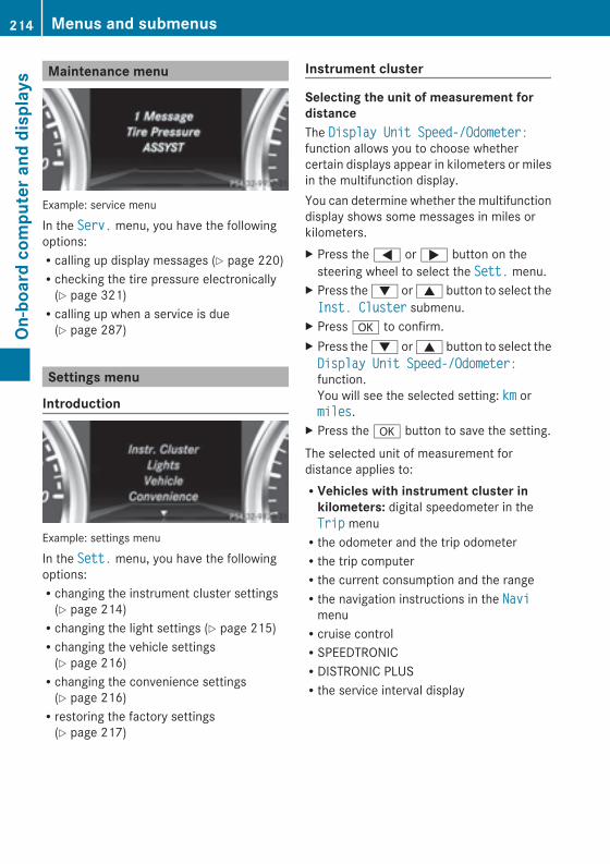
Maintenance menu
Example: service menu
In the Serv.Serv. menu, you have the followingoptions:Rcalling up display messages (Y page 220)Rchecking the tire pressure electronically(Y page 321)Rcalling up when a service is due(Y page 287)
Settings menu
Introduction
Example: settings menu
In the Sett.Sett. menu, you have the followingoptions:Rchanging the instrument cluster settings(Y page 214)Rchanging the light settings (Y page 215)Rchanging the vehicle settings(Y page 216)Rchanging the convenience settings(Y page 216)Rrestoring the factory settings(Y page 217)
Instrument cluster
Selecting the unit of measurement fordistanceThe Display Unit Speed-/Odometer:Display Unit Speed-/Odometer:function allows you to choose whethercertain displays appear in kilometers or milesin the multifunction display.You can determine whether the multifunctiondisplay shows some messages in miles orkilometers.X Press the= or; button on thesteering wheel to select the Sett.Sett. menu.
X Press the: or9 button to select theInst. ClusterInst. Cluster submenu.
X Pressa to confirm.X Press the: or9 button to select theDisplay Unit Speed-/Odometer:Display Unit Speed-/Odometer:function.You will see the selected setting: kmkm ormilesmiles.
X Press thea button to save the setting.
The selected unit of measurement fordistance applies to:RVehicles with instrument cluster inkilometers: digital speedometer in theTripTrip menuRthe odometer and the trip odometerRthe trip computerRthe current consumption and the rangeRthe navigation instructions in the NaviNavimenuRcruise controlRSPEEDTRONICRDISTRONIC PLUSRthe service interval display
214 Menus and submenusOn
-board
computerand
displays
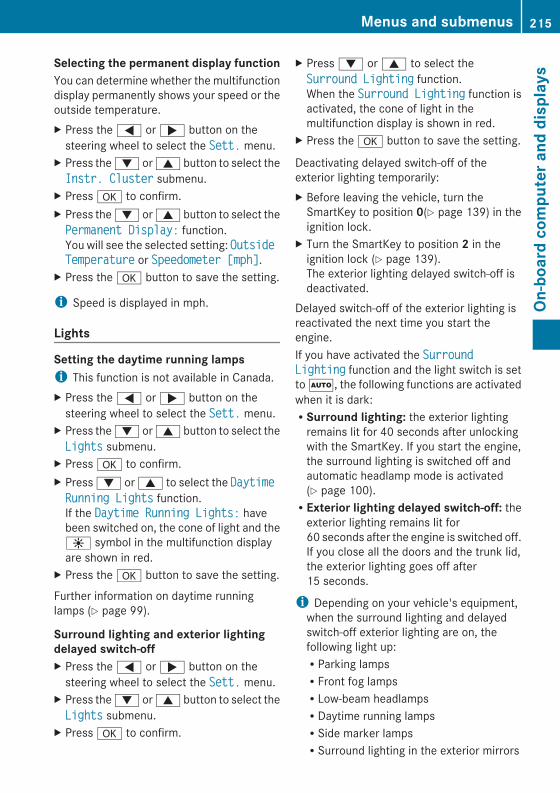
Selecting the permanent display functionYou can determine whether the multifunctiondisplay permanently shows your speed or theoutside temperature.X Press the= or; button on thesteering wheel to select the Sett.Sett. menu.
X Press the: or9 button to select theInstr. ClusterInstr. Cluster submenu.
X Pressa to confirm.X Press the: or9 button to select thePermanent Display:Permanent Display: function.You will see the selected setting: OutsideOutsideTemperatureTemperature or Speedometer [mph]Speedometer [mph].
X Press thea button to save the setting.
i Speed is displayed in mph.
Lights
Setting the daytime running lampsi This function is not available in Canada.X Press the= or; button on thesteering wheel to select the Sett.Sett. menu.
X Press the: or9 button to select theLightsLights submenu.
X Pressa to confirm.X Press: or9 to select the DaytimeDaytimeRunning LightsRunning Lights function.If the Daytime Running Lights:Daytime Running Lights: havebeen switched on, the cone of light and theW symbol in the multifunction displayare shown in red.
X Press thea button to save the setting.
Further information on daytime runninglamps (Y page 99).
Surround lighting and exterior lightingdelayed switch-offX Press the= or; button on thesteering wheel to select the Sett.Sett. menu.
X Press the: or9 button to select theLightsLights submenu.
X Pressa to confirm.
X Press: or9 to select theSurround LightingSurround Lighting function.When the Surround LightingSurround Lighting function isactivated, the cone of light in themultifunction display is shown in red.
X Press thea button to save the setting.
Deactivating delayed switch-off of theexterior lighting temporarily:X Before leaving the vehicle, turn theSmartKey to position 0(Y page 139) in theignition lock.
X Turn the SmartKey to position 2 in theignition lock (Y page 139).The exterior lighting delayed switch-off isdeactivated.
Delayed switch-off of the exterior lighting isreactivated the next time you start theengine.If you have activated the SurroundSurroundLightingLighting function and the light switch is settoÃ, the following functions are activatedwhen it is dark:RSurround lighting: the exterior lightingremains lit for 40 seconds after unlockingwith the SmartKey. If you start the engine,the surround lighting is switched off andautomatic headlamp mode is activated(Y page 100).RExterior lighting delayed switch-off: theexterior lighting remains lit for60 seconds after the engine is switched off.If you close all the doors and the trunk lid,the exterior lighting goes off after15 seconds.
i Depending on your vehicle's equipment,when the surround lighting and delayedswitch-off exterior lighting are on, thefollowing light up:RParking lampsRFront fog lampsRLow-beam headlampsRDaytime running lampsRSide marker lampsRSurround lighting in the exterior mirrors
Menus and submenus 215
On-board
computerand
displays
Z
Activating/deactivating the interiorlighting delayed switch-offIf you activate the Interior LightingInterior LightingDelayDelay function, the interior lighting remainson for 20 seconds after you remove theSmartKey from the ignition lock.X Press the= or; button on thesteering wheel to select the Sett.Sett. menu.
X Press the: or9 button to select theLightsLights submenu.
X Pressa to confirm.X Press: or9 to select theInterior Lighting DelayInterior Lighting Delay function.When the Interior Lighting DelayInterior Lighting Delayfunction is activated, the vehicle interior isdisplayed in red in the multifunctiondisplay.
X Press thea button to save the setting.
Vehicle
Activating/deactivating the automaticdoor locking mechanismIf you activate the Automatic Door LockAutomatic Door Lockfunction, the vehicle is centrally locked abovea speed of around 9 mph (15 km/h).X Press the= or; button on thesteering wheel to select the Sett.Sett. menu.
X Press the: or9 button to select theVehicleVehicle submenu.
X Pressa to confirm.X Press: or9 to select theAutomatic Door LockAutomatic Door Lock function.When the AutomaticAutomatic DoorDoor LockLock functionis activated, the vehicle doors are displayedin red in the multifunction display.
X Press thea button to save the setting.
For further information on the automaticlocking feature, see (Y page 75).
Activating/deactivating the acousticlocking verification signalIf you switch on the AcousticAcoustic LockLock function,an acoustic signal sounds when you lock thevehicle.X Press the= or; button on thesteering wheel to select the Sett.Sett. menu.
X Press: or9 to select the VehicleVehiclesubmenu.
X Pressa to confirm.X Press the: or9 button to select theAcoustic LockAcoustic Lock function.If the AcousticAcoustic LockLock function is activated,the& symbol in the multifunctiondisplay lights up red.
X Press thea button to save the setting.
Convenience
Activating/deactivating the EASY-ENTRY/EXIT featureG WARNINGYou must make sure no one can becometrapped or injured by the moving steeringwheel when the easy-entry/exit feature isactivated.To stop steering wheel movement, movesteering wheel adjustment lever or press oneof the memory position buttons.Do not leave children unattended in thevehicle, or with access to an unlocked vehicle.Children could open the driver's door andunintentionally activate the easy-entry/exitfeature, which could result in an accidentand/or serious personal injury.
X Press the= or; button on thesteering wheel to select the Sett.Sett. menu.
X Press the: or9 button to select theConvenienceConvenience submenu.
X Pressa to confirm.
216 Menus and submenusOn
-board
computerand
displays
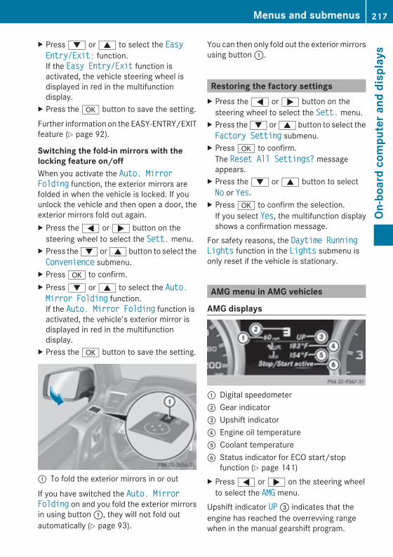
X Press: or9 to select the EasyEasyEntry/Exit:Entry/Exit: function.If the Easy Entry/ExitEasy Entry/Exit function isactivated, the vehicle steering wheel isdisplayed in red in the multifunctiondisplay.
X Press thea button to save the setting.
Further information on the EASY-ENTRY/EXITfeature (Y page 92).
Switching the fold-in mirrors with thelocking feature on/offWhen you activate the Auto. MirrorAuto. MirrorFoldingFolding function, the exterior mirrors arefolded in when the vehicle is locked. If youunlock the vehicle and then open a door, theexterior mirrors fold out again.X Press the= or; button on thesteering wheel to select the Sett.Sett. menu.
X Press the: or9 button to select theConvenienceConvenience submenu.
X Pressa to confirm.X Press: or9 to select the Auto.Auto.Mirror FoldingMirror Folding function.If the Auto. Mirror FoldingAuto. Mirror Folding function isactivated, the vehicle's exterior mirror isdisplayed in red in the multifunctiondisplay.
X Press thea button to save the setting.
: To fold the exterior mirrors in or out
If you have switched the Auto. MirrorAuto. MirrorFoldingFolding on and you fold the exterior mirrorsin using button:, they will not fold outautomatically (Y page 93).
You can then only fold out the exteriormirrorsusing button:.
Restoring the factory settingsX Press the= or; button on thesteering wheel to select the Sett.Sett. menu.
X Press the: or9 button to select theFactory SettingFactory Setting submenu.
X Pressa to confirm.The Reset All Settings?Reset All Settings? messageappears.
X Press the: or9 button to selectNoNo or YesYes.
X Pressa to confirm the selection.If you select YesYes, the multifunction displayshows a confirmation message.
For safety reasons, the Daytime RunningDaytime RunningLightsLights function in the LightsLights submenu isonly reset if the vehicle is stationary.
AMG menu in AMG vehicles
AMG displays
: Digital speedometer; Gear indicator= Upshift indicator? Engine oil temperatureA Coolant temperatureB Status indicator for ECO start/stop
function (Y page 141)X Press= or; on the steering wheelto select the AMGAMG menu.
Upshift indicator UPUP= indicates that theengine has reached the overrevving rangewhen in the manual gearshift program.
Menus and submenus 217
On-board
computerand
displays
Z
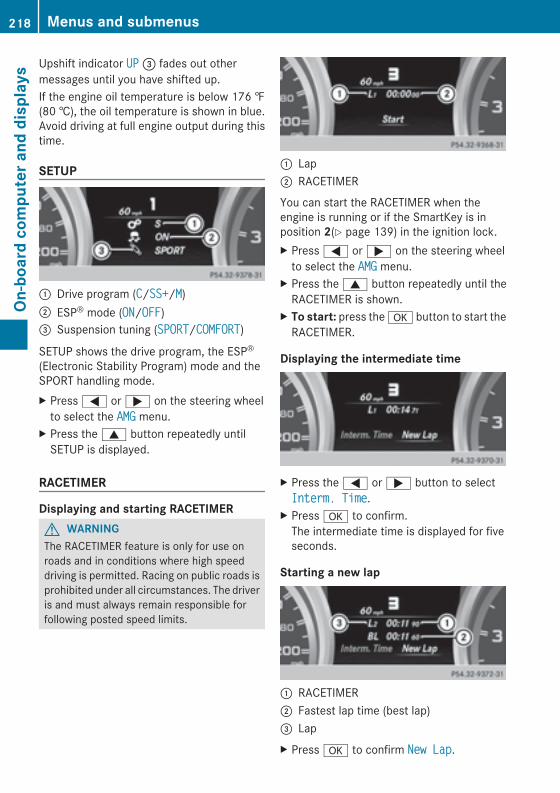
Upshift indicator UPUP= fades out othermessages until you have shifted up.If the engine oil temperature is below 176 ‡(80 †), the oil temperature is shown in blue.Avoid driving at full engine output during thistime.
SETUP
: Drive program (CC/SS+SS+/MM); ESP® mode (ONON/OFFOFF)= Suspension tuning (SPORTSPORT/COMFORTCOMFORT)SETUP shows the drive program, the ESP®(Electronic Stability Program) mode and theSPORT handling mode.X Press= or; on the steering wheelto select the AMGAMG menu.
X Press the9 button repeatedly untilSETUP is displayed.
RACETIMER
Displaying and starting RACETIMERG WARNINGThe RACETIMER feature is only for use onroads and in conditions where high speeddriving is permitted. Racing on public roads isprohibited under all circumstances. The driveris and must always remain responsible forfollowing posted speed limits.
: Lap; RACETIMER
You can start the RACETIMER when theengine is running or if the SmartKey is inposition 2(Y page 139) in the ignition lock.X Press= or; on the steering wheelto select the AMGAMG menu.
X Press the9 button repeatedly until theRACETIMER is shown.
X To start: press thea button to start theRACETIMER.
Displaying the intermediate time
X Press the= or; button to selectInterm. TimeInterm. Time.
X Pressa to confirm.The intermediate time is displayed for fiveseconds.
Starting a new lap
: RACETIMER; Fastest lap time (best lap)= LapX Pressa to confirm New LapNew Lap.
218 Menus and submenusOn
-board
computerand
displays
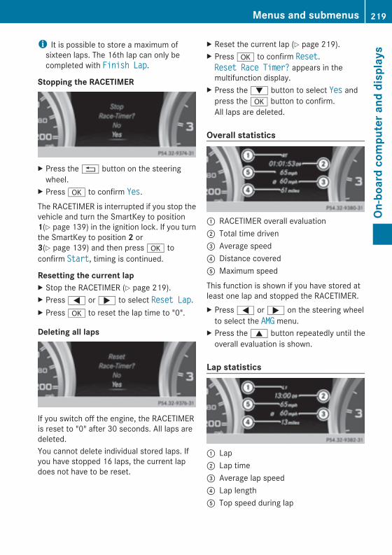
i It is possible to store a maximum ofsixteen laps. The 16th lap can only becompleted with Finish LapFinish Lap.
Stopping the RACETIMER
X Press the% button on the steeringwheel.
X Pressa to confirm YesYes.The RACETIMER is interrupted if you stop thevehicle and turn the SmartKey to position1(Y page 139) in the ignition lock. If you turnthe SmartKey to position 2 or3(Y page 139) and then pressa toconfirm StartStart, timing is continued.Resetting the current lapX Stop the RACETIMER (Y page 219).X Press= or; to select Reset LapReset Lap.X Pressa to reset the lap time to "0".
Deleting all laps
If you switch off the engine, the RACETIMERis reset to "0" after 30 seconds. All laps aredeleted.You cannot delete individual stored laps. Ifyou have stopped 16 laps, the current lapdoes not have to be reset.
X Reset the current lap (Y page 219).X Pressa to confirm ResetReset.Reset Race Timer?Reset Race Timer? appears in themultifunction display.
X Press the: button to select YesYes andpress thea button to confirm.All laps are deleted.
Overall statistics
: RACETIMER overall evaluation; Total time driven= Average speed? Distance coveredA Maximum speed
This function is shown if you have stored atleast one lap and stopped the RACETIMER.X Press= or; on the steering wheelto select the AMGAMG menu.
X Press the9 button repeatedly until theoverall evaluation is shown.
Lap statistics
: Lap; Lap time= Average lap speed? Lap lengthA Top speed during lap
Menus and submenus 219
On-board
computerand
displays
Z
This function is only available if you havestored at least two laps and have stopped theRACETIMER.X Press= or; on the steering wheelto select the AMGAMG menu.
X Press the9 button repeatedly until thelap evaluation is shown.Each lap is shown in a separate submenu.The fastest lap is indicated by flashingsymbol:.
X Press the9 or: button to select adifferent lap evaluation.
Display messages
Introduction
General notesDisplaymessages appear in themultifunctiondisplay.Display messages with graphic displays maybe shown in simplified form in the Operator'sManual and may differ from the messagesshown in the multifunction display.Please respond in accordance with thedisplay messages and follow the additionalnotes in this Operator's Manual.Certain display messages are accompaniedby an audible warning tone or a continuoustone.When you stop and park the vehicle, pleaseobserve the notes on:RHOLD function (Y page 188)RParking (Y page 156)
Hiding display messagesX Press thea or% button on thesteeringwheel to hide the displaymessage.The display message is cleared.
Display messages with a high priority areshown in red.You cannot hide display messages of thehighest priority. The multifunction display
shows these messages continuously until thecauses for the messages have beenremedied.
Message memory menuThe on-board computer saves certain displaymessages. You can call up the displaymessages in themessage memory.X Press the= or; button on thesteering wheel to select the Serv.Serv. menu.If there are display messages, themultifunction display shows 2 Messages2 Messages,for example.
X Press the9 or: button to select theentry, e.g. 2 Messages2 Messages.
X Pressa to confirm.X Press the9 or: button to scrollthrough the display messages.
When the ignition is switched off, all displaymessages are deleted, apart from some high-priority displaymessages. Once the causes ofthe high-priority display messages have beenrectified, the corresponding displaymessages are also deleted.
220 Display messagesOn
-board
computerand
displays
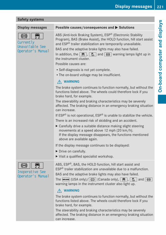
Safety systems
Display messages Possible causes/consequences andMM Solutions
!÷CurrentlyCurrentlyUnavailable SeeUnavailable SeeOperator's ManualOperator's Manual
ABS (Anti-lock Braking System), ESP® (Electronic StabilityProgram), BAS (Brake Assist), the HOLD function, hill start assistand ESP® trailer stabilization are temporarily unavailable.BAS and the adaptive brake lights may also have failed.In addition, the ÷, å and ! warning lamps light up inthe instrument cluster.Possible causes are:RSelf-diagnosis is not yet complete.RThe on-board voltage may be insufficient.
G WARNINGThe brake system continues to function normally, but without thefunctions listed above. The wheels could therefore lock if youbrake hard, for example.The steerability and braking characteristics may be severelyaffected. The braking distance in an emergency braking situationcan increase.If ESP® is not operational, ESP® is unable to stabilize the vehicle.There is an increased risk of skidding and an accident.X Carefully drive a suitable distance making slight steeringmovements at a speed above 12 mph (20 km/h).If the display message disappears, the functions mentionedabove are available again.
If the display message continues to be displayed:X Drive on carefully.X Visit a qualified specialist workshop.
!÷Inoperative SeeInoperative SeeOperator's ManualOperator's Manual
ABS, ESP®, BAS, the HOLD function, hill start assist andESP® trailer stabilization are unavailable due to a malfunction.BAS and the adaptive brake lights may also have failed.The$ (USA only)/J (Canada only), ÷, å and !warning lamps in the instrument cluster also light up.
G WARNINGThe brake system continues to function normally, but without thefunctions listed above. The wheels could therefore lock if youbrake hard, for example.The steerability and braking characteristics may be severelyaffected. The braking distance in an emergency braking situationcan increase.
Display messages 221
On-board
computerand
displays
Z
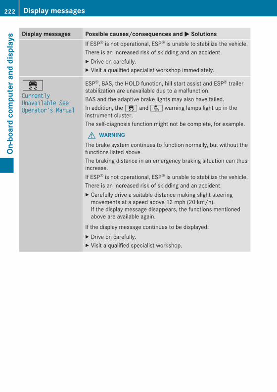
Display messages Possible causes/consequences andMM SolutionsIf ESP® is not operational, ESP® is unable to stabilize the vehicle.There is an increased risk of skidding and an accident.X Drive on carefully.X Visit a qualified specialist workshop immediately.
÷CurrentlyCurrentlyUnavailable SeeUnavailable SeeOperator's ManualOperator's Manual
ESP®, BAS, the HOLD function, hill start assist and ESP® trailerstabilization are unavailable due to a malfunction.BAS and the adaptive brake lights may also have failed.In addition, the ÷ and å warning lamps light up in theinstrument cluster.The self-diagnosis function might not be complete, for example.
G WARNINGThe brake system continues to function normally, but without thefunctions listed above.The braking distance in an emergency braking situation can thusincrease.If ESP® is not operational, ESP® is unable to stabilize the vehicle.There is an increased risk of skidding and an accident.X Carefully drive a suitable distance making slight steeringmovements at a speed above 12 mph (20 km/h).If the display message disappears, the functions mentionedabove are available again.
If the display message continues to be displayed:X Drive on carefully.X Visit a qualified specialist workshop.
222 Display messagesOn
-board
computerand
displays
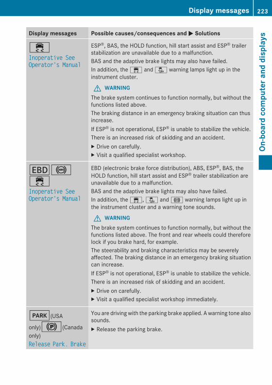
Display messages Possible causes/consequences andMM Solutions
÷Inoperative SeeInoperative SeeOperator's ManualOperator's Manual
ESP®, BAS, the HOLD function, hill start assist and ESP® trailerstabilization are unavailable due to a malfunction.BAS and the adaptive brake lights may also have failed.In addition, the ÷ and å warning lamps light up in theinstrument cluster.
G WARNINGThe brake system continues to function normally, but without thefunctions listed above.The braking distance in an emergency braking situation can thusincrease.If ESP® is not operational, ESP® is unable to stabilize the vehicle.There is an increased risk of skidding and an accident.X Drive on carefully.X Visit a qualified specialist workshop.
T!÷Inoperative SeeInoperative SeeOperator's ManualOperator's Manual
EBD (electronic brake force distribution), ABS, ESP®, BAS, theHOLD function, hill start assist and ESP® trailer stabilization areunavailable due to a malfunction.BAS and the adaptive brake lights may also have failed.In addition, the ÷, å and ! warning lamps light up inthe instrument cluster and a warning tone sounds.
G WARNINGThe brake system continues to function normally, but without thefunctions listed above. The front and rear wheels could thereforelock if you brake hard, for example.The steerability and braking characteristics may be severelyaffected. The braking distance in an emergency braking situationcan increase.If ESP® is not operational, ESP® is unable to stabilize the vehicle.There is an increased risk of skidding and an accident.X Drive on carefully.X Visit a qualified specialist workshop immediately.
F(USA
only)!(Canadaonly)ReleaseRelease Park.Park. BrakeBrake
You are driving with the parking brake applied. A warning tone alsosounds.X Release the parking brake.
Display messages 223
On-board
computerand
displays
Z
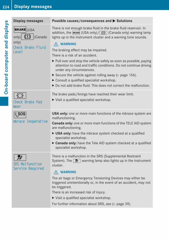
Display messages Possible causes/consequences andMM Solutions
$(USA
only)J(Canadaonly)Check Brake FluidCheck Brake FluidLevelLevel
There is not enough brake fluid in the brake fluid reservoir. Inaddition, the$ (USA only)/J (Canada only) warning lamplights up in the instrument cluster and a warning tone sounds.
G WARNINGThe braking effect may be impaired.There is a risk of an accident.X Pull over and stop the vehicle safely as soon as possible, payingattention to road and traffic conditions. Do not continue drivingunder any circumstances.
X Secure the vehicle against rolling away (Y page 156).X Consult a qualified specialist workshop.X Do not add brake fluid. This does not correct the malfunction.
#Check Brake PadCheck Brake PadWearWear
The brake pads/linings have reached their wear limit.X Visit a qualified specialist workshop.
Gmbrace Inoperativembrace Inoperative
USA only: one or more main functions of the mbrace system aremalfunctioning.Canada only: one or more main functions of the TELE AID systemare malfunctioning.X USA only: have the mbrace system checked at a qualifiedspecialist workshop.
X Canada only: have the Tele AID system checked at a qualifiedspecialist workshop.
6SRS MalfunctionSRS MalfunctionService RequiredService Required
There is a malfunction in the SRS (Supplemental RestraintSystem). The 6 warning lamp also lights up in the instrumentcluster.
G WARNINGThe air bags or Emergency Tensioning Devices may either betriggered unintentionally or, in the event of an accident, may notbe triggered.There is an increased risk of injury.X Visit a qualified specialist workshop.For further information about SRS, see (Y page 39).
224 Display messagesOn
-board
computerand
displays
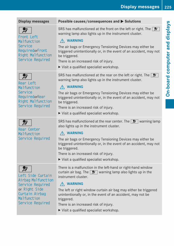
Display messages Possible causes/consequences andMM Solutions
6Front LeftFront LeftMalfunctionMalfunctionServiceServiceRequiredRequiredorFrontFrontRight MalfunctionRight MalfunctionService RequiredService Required
SRS has malfunctioned at the front on the left or right. The 6warning lamp also lights up in the instrument cluster.
G WARNINGThe air bags or Emergency Tensioning Devices may either betriggered unintentionally or, in the event of an accident, may notbe triggered.There is an increased risk of injury.X Visit a qualified specialist workshop.
6Rear LeftRear LeftMalfunctionMalfunctionServiceServiceRequiredRequiredorRearRearRight MalfunctionRight MalfunctionService RequiredService Required
SRS has malfunctioned at the rear on the left or right. The 6warning lamp also lights up in the instrument cluster.
G WARNINGThe air bags or Emergency Tensioning Devices may either betriggered unintentionally or, in the event of an accident, may notbe triggered.There is an increased risk of injury.X Visit a qualified specialist workshop.
6Rear CenterRear CenterMalfunctionMalfunctionService RequiredService Required
SRS has malfunctioned at the rear center. The 6 warning lampalso lights up in the instrument cluster.
G WARNINGThe air bags or Emergency Tensioning Devices may either betriggered unintentionally or, in the event of an accident, may notbe triggered.There is an increased risk of injury.X Visit a qualified specialist workshop.
6Left Side CurtainLeft Side CurtainAirbagAirbag MalfunctionMalfunctionService RequiredService Requiredor Right SideRight SideCurtain AirbagCurtain AirbagMalfunctionMalfunctionService RequiredService Required
There is a malfunction in the left-hand or right-hand windowcurtain air bag. The 6 warning lamp also lights up in theinstrument cluster.
G WARNINGThe left or right window curtain air bag may either be triggeredunintentionally or, in the event of an accident, may not betriggered.There is an increased risk of injury.X Visit a qualified specialist workshop.
Display messages 225
On-board
computerand
displays
Z
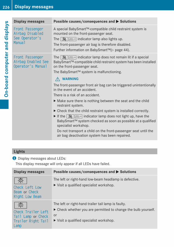
Display messages Possible causes/consequences andMM Solutions
Front PassengerFront PassengerAirbag DisabledAirbag DisabledSee Operator'sSee Operator'sManualManual
A special BabySmart™-compatible child restraint system ismounted on the front-passenger seat.The 45 indicator lamp also lights up.The front-passenger air bag is therefore disabled.Further information on BabySmart™(Y page 44).
Front PassengerFront PassengerAirbagAirbag EnabledEnabled SeeSeeOperator's ManualOperator's Manual
The 45 indicator lamp does not remain lit if a specialBabySmart™-compatible child restraint system has been installedon the front-passenger seat.The BabySmart™ system is malfunctioning.
G WARNINGThe front-passenger front air bag can be triggered unintentionallyin the event of an accident.There is a risk of an accident.X Make sure there is nothing between the seat and the childrestraint system.
X Check that the child restraint system is installed correctly.X If the 45 indicator lamp does not light up, have theBabySmart™ system checked as soon as possible at a qualifiedspecialist workshop.Do not transport a child on the front-passenger seat until theair bag deactivation system has been repaired.
Lightsi Display messages about LEDs:This display message will only appear if all LEDs have failed.
Display messages Possible causes/consequences andMM Solutions
bCheck Left LowCheck Left LowBeamBeam or CheckCheckRight Low BeamRight Low Beam
The left or right-hand low-beam headlamp is defective.X Visit a qualified specialist workshop.
bCheckCheck TrailerTrailer LeftLeftTail LampTail Lamp or CheckCheckTrailerTrailer RightRight TailTailLampLamp
The left or right-hand trailer tail lamp is faulty.X Check whether you are permitted to change the bulb yourself.orX Visit a qualified specialist workshop.
226 Display messagesOn
-board
computerand
displays
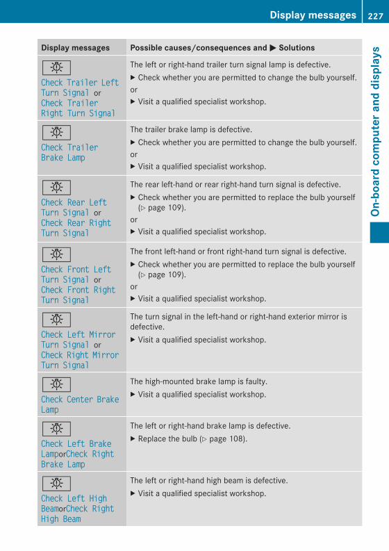
Display messages Possible causes/consequences andMM Solutions
bCheckCheck TrailerTrailer LeftLeftTurn SignalTurn Signal orCheck TrailerCheck TrailerRight Turn SignalRight Turn Signal
The left or right-hand trailer turn signal lamp is defective.X Check whether you are permitted to change the bulb yourself.orX Visit a qualified specialist workshop.
bCheck TrailerCheck TrailerBrake LampBrake Lamp
The trailer brake lamp is defective.X Check whether you are permitted to change the bulb yourself.orX Visit a qualified specialist workshop.
bCheck Rear LeftCheck Rear LeftTurn SignalTurn Signal orCheck Rear RightCheck Rear RightTurn SignalTurn Signal
The rear left-hand or rear right-hand turn signal is defective.X Check whether you are permitted to replace the bulb yourself(Y page 109).
orX Visit a qualified specialist workshop.
bCheck Front LeftCheck Front LeftTurn SignalTurn Signal orCheck Front RightCheck Front RightTurn SignalTurn Signal
The front left-hand or front right-hand turn signal is defective.X Check whether you are permitted to replace the bulb yourself(Y page 109).
orX Visit a qualified specialist workshop.
bCheck Left MirrorCheck Left MirrorTurn SignalTurn Signal orCheckCheck RightRight MirrorMirrorTurn SignalTurn Signal
The turn signal in the left-hand or right-hand exterior mirror isdefective.X Visit a qualified specialist workshop.
bCheckCheck CenterCenter BrakeBrakeLampLamp
The high-mounted brake lamp is faulty.X Visit a qualified specialist workshop.
bCheck Left BrakeCheck Left BrakeLampLamporCheck RightCheck RightBrake LampBrake Lamp
The left or right-hand brake lamp is defective.X Replace the bulb (Y page 108).
bCheck Left HighCheck Left HighBeamBeamorCheck RightCheck RightHigh BeamHigh Beam
The left or right-hand high beam is defective.X Visit a qualified specialist workshop.
Display messages 227
On-board
computerand
displays
Z
Display messages Possible causes/consequences andMM Solutions
bLicense Plate LampLicense Plate Lamp
There is a short circuit in the LED lamps. The LEDs have beenswitched off.X Visit a qualified specialist workshop.
bCheck Left FogCheck Left FogLampLamporCheck RightCheck RightFog LampFog Lamp
The left-hand or right-hand front fog lamp is defective.X Replace the bulb (Y page 108).
bRear Fog LampRear Fog Lamp
The rear fog lamp is defective.X Check whether you are permitted to replace the bulb yourself(Y page 109).
orX Visit a qualified specialist workshop.
bCheck Front LeftCheck Front LeftParking LampParking Lamp orCheck Front RightCheck Front RightParking LampParking Lamp
The front left or front right parking or standing lamp is defective.X Check whether you are permitted to replace the bulb yourself(Y page 109).
orX Visit a qualified specialist workshop.
bBackup LightBackup Light
The backup lamp is defective.X Replace the bulb (Y page 108).
bCheck Front LeftCheck Front LeftSidemarkerSidemarkerLampLamporCheck FrontCheck FrontRight SidemarkerRight SidemarkerLampLamp
The left or right front side marker lamp is defective.X Check whether you are permitted to replace the bulb yourself(Y page 109).
orX Visit a qualified specialist workshop.
bCheck Left TailCheck Left TailLampLamporCheck RightCheck RightTail LampTail Lamp
The left or right-hand tail lamp is defective.X Check whether you are permitted to replace the bulb yourself(Y page 109).
orX Visit a qualified specialist workshop.
228 Display messagesOn
-board
computerand
displays
Display messages Possible causes/consequences andMM Solutions
bCheckCheck LeftLeft DaytimeDaytimeRunning LightRunning Light orCheck RightCheck RightDaytime RunningDaytime RunningLightLight
The left or right-hand daytime running lamp is defective.X Visit a qualified specialist workshop.
bMalfunction SeeMalfunction SeeOperator's ManualOperator's Manual
The exterior lighting is defective.X Visit a qualified specialist workshop.
bAutoAuto LampLamp FunctionFunctionInoperativeInoperative
The light sensor is defective.X Visit a qualified specialist workshop.
bSwitch Off LightsSwitch Off Lights
The lights are still switched on when you leave the vehicle. Awarning tone also sounds.X Turn the light switch toÃ.
Engine
Display messages Possible causes/consequences andMM Solutions
+Check CoolantCheck CoolantLevel SeeLevel SeeOperator's ManualOperator's Manual
The coolant level is too low.X Add coolant, observing the warning notes before doing so(Y page 285).
X Have the coolant system checked at a qualified specialistworkshop if the coolant needs topping upmore often than usual.
? The fan motor is faulty.X At coolant temperatures below 248‡ (120†), drive to the nextqualified specialist workshop.
X Avoid heavy loads on the engine as you do so, e.g. driving inmountainous terrain and stop-start traffic.
Display messages 229
On-board
computerand
displays
Z
Display messages Possible causes/consequences andMM Solutions
?Coolant Too HotCoolant Too HotStop Vehicle TurnStop Vehicle TurnEngine OffEngine Off
The coolant is too hot.A warning tone also sounds.
G WARNINGDo not drive when your engine is overheated. This can cause somefluids which may have leaked into the engine compartment tocatch fire.Steam from the overheated engine can also cause serious burnswhich can occur just by opening the hood.There is a risk of injury.X Pull over and stop the vehicle safely and switch off the engine,paying attention to road and traffic conditions.
X Secure the vehicle against rolling away (Y page 156).X Leave the vehicle and keep a safe distance from the vehicle untilthe engine has cooled down.
X Make sure that the air supply to the engine radiator is notblocked, e.g. by snow, slush or ice.
X Do not start the engine again until the display message goes outand the coolant temperature is below 248 ‡ (120 †).Otherwise, the engine could be damaged.
X Pay attention to the coolant temperature display.X If the temperature increases again, visit a qualified specialistworkshop immediately.
Under normal operating conditions and with the specified coolantlevel, the coolant temperature may rise to 248 ‡ (120 †).
The poly-V-belt may have torn.X Pull over and stop the vehicle safely and switch off the engine,paying attention to road and traffic conditions.
X Check the poly-V-belt.If the poly-V-belt is torn:! Do not continue driving. The engine could otherwise overheat.X Consult a qualified specialist workshop.If the poly-V-belt is not damaged:X Wait until the display message disappears before restarting theengine. Otherwise, the engine could be damaged.
X Pay attention to the coolant temperature display.X Visit a qualified specialist workshop.
230 Display messagesOn
-board
computerand
displays
Display messages Possible causes/consequences andMM Solutions
# The battery is not being charged.A warning tone also sounds.Possible causes are:Ra defective alternatorRa torn poly-V-beltRa malfunction in the electronicsX Pull over and stop the vehicle safely and switch off the engine,paying attention to road and traffic conditions.
X Open the hood.X Check whether the poly-V-belt is torn.If the poly-V-belt is torn:! Do not continue driving. The engine could otherwise overheat.X Consult a qualified specialist workshop.If the poly-V-belt is not damaged:X Visit a qualified specialist workshop.
4Check Engine OilCheck Engine OilAt Next RefuelingAt Next Refueling
The engine oil level has dropped to the minimum level.A warning tone also sounds.X Check the oil level when next refueling, at the latest(Y page 283).
X If necessary, add engine oil (Y page 284).X Have the engine checked at a qualified specialist workshop ifengine oil needs to be added more often than usual.
! Avoid long journeys with too little engine oil. The engine willotherwise be damaged.
Information on approved engine oils can be obtained from anyqualified specialist workshop or on the Internet at http://www.mbusa.com (USA only).
4Engine Oil LevelEngine Oil LevelLow Stop VehicleLow Stop VehicleTurn Engine OffTurn Engine Off
The engine oil level is too low. There is a risk of engine damage.X Pull over and stop the vehicle safely and switch off the engine,paying attention to road and traffic conditions.
X Add engine oil (Y page 284) and check the oil level(Y page 283).
Display messages 231
On-board
computerand
displays
Z
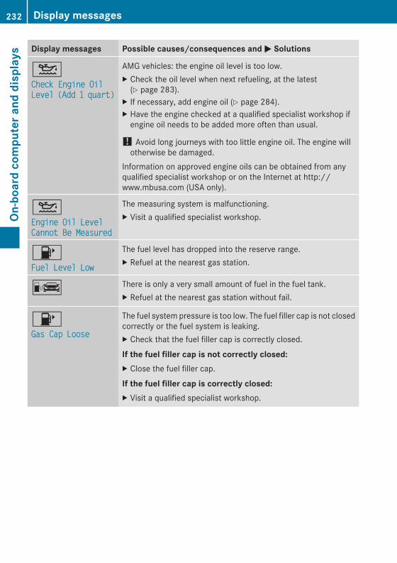
Display messages Possible causes/consequences andMM Solutions
4Check Engine OilCheck Engine OilLevelLevel (Add(Add 11 quart)quart)
AMG vehicles: the engine oil level is too low.X Check the oil level when next refueling, at the latest(Y page 283).
X If necessary, add engine oil (Y page 284).X Have the engine checked at a qualified specialist workshop ifengine oil needs to be added more often than usual.
! Avoid long journeys with too little engine oil. The engine willotherwise be damaged.
Information on approved engine oils can be obtained from anyqualified specialist workshop or on the Internet at http://www.mbusa.com (USA only).
4Engine Oil LevelEngine Oil LevelCannot Be MeasuredCannot Be Measured
The measuring system is malfunctioning.X Visit a qualified specialist workshop.
8Fuel Level LowFuel Level Low
The fuel level has dropped into the reserve range.X Refuel at the nearest gas station.
C There is only a very small amount of fuel in the fuel tank.X Refuel at the nearest gas station without fail.
8Gas Cap LooseGas Cap Loose
The fuel system pressure is too low. The fuel filler cap is not closedcorrectly or the fuel system is leaking.X Check that the fuel filler cap is correctly closed.
If the fuel filler cap is not correctly closed:X Close the fuel filler cap.
If the fuel filler cap is correctly closed:X Visit a qualified specialist workshop.
232 Display messagesOn
-board
computerand
displays
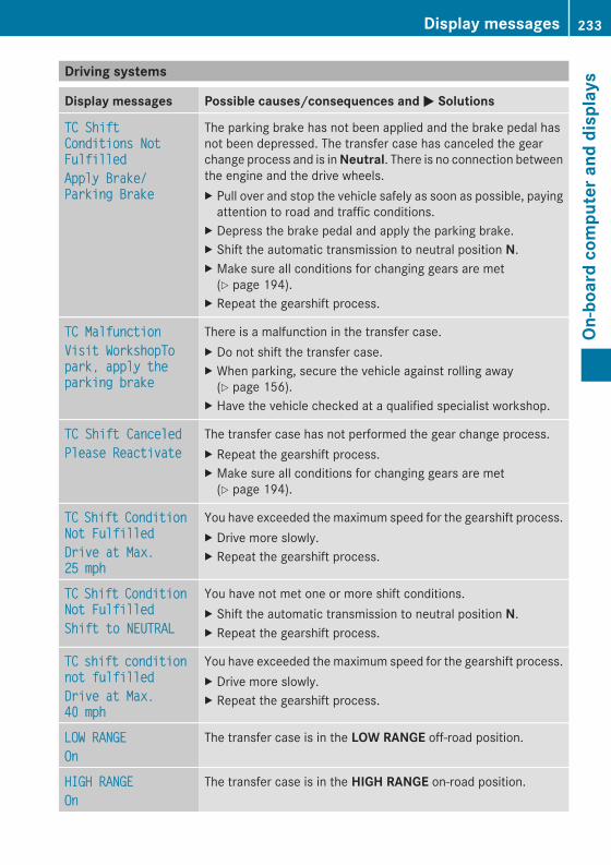
Driving systems
Display messages Possible causes/consequences and MM Solutions
TC ShiftTC ShiftConditions NotConditions NotFulfilledFulfilledApply Brake/Apply Brake/Parking BrakeParking Brake
The parking brake has not been applied and the brake pedal hasnot been depressed. The transfer case has canceled the gearchange process and is inNeutral. There is no connection betweenthe engine and the drive wheels.X Pull over and stop the vehicle safely as soon as possible, payingattention to road and traffic conditions.
X Depress the brake pedal and apply the parking brake.X Shift the automatic transmission to neutral position N.X Make sure all conditions for changing gears are met(Y page 194).
X Repeat the gearshift process.
TC MalfunctionTC MalfunctionVisit WorkshopToVisit WorkshopTopark, apply thepark, apply theparking brakeparking brake
There is a malfunction in the transfer case.X Do not shift the transfer case.X When parking, secure the vehicle against rolling away(Y page 156).
X Have the vehicle checked at a qualified specialist workshop.
TC Shift CanceledTC Shift CanceledPlease ReactivatePlease Reactivate
The transfer case has not performed the gear change process.X Repeat the gearshift process.X Make sure all conditions for changing gears are met(Y page 194).
TCTC ShiftShift ConditionConditionNot FulfilledNot FulfilledDrive at Max.Drive at Max.25 mph25 mph
You have exceeded the maximum speed for the gearshift process.X Drive more slowly.X Repeat the gearshift process.
TCTC ShiftShift ConditionConditionNot FulfilledNot FulfilledShift to NEUTRALShift to NEUTRAL
You have not met one or more shift conditions.X Shift the automatic transmission to neutral position N.X Repeat the gearshift process.
TCTC shiftshift conditionconditionnot fulfillednot fulfilledDrive at Max.Drive at Max.40 mph40 mph
You have exceeded the maximum speed for the gearshift process.X Drive more slowly.X Repeat the gearshift process.
LOW RANGELOW RANGEOnOn
The transfer case is in the LOW RANGE off-road position.
HIGH RANGEHIGH RANGEOnOn
The transfer case is in the HIGH RANGE on-road position.
Display messages 233
On-board
computerand
displays
Z
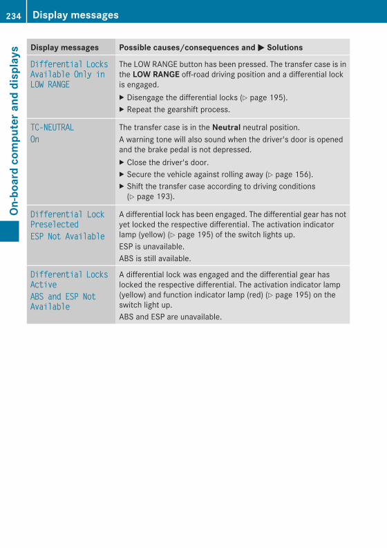
Display messages Possible causes/consequences andMM Solutions
DifferentialDifferential LocksLocksAvailable Only inAvailable Only inLOW RANGELOW RANGE
The LOW RANGE button has been pressed. The transfer case is inthe LOW RANGE off-road driving position and a differential lockis engaged.X Disengage the differential locks (Y page 195).X Repeat the gearshift process.
TC-NEUTRALTC-NEUTRALOnOn
The transfer case is in the Neutral neutral position.A warning tone will also sound when the driver's door is openedand the brake pedal is not depressed.X Close the driver's door.X Secure the vehicle against rolling away (Y page 156).X Shift the transfer case according to driving conditions(Y page 193).
Differential LockDifferential LockPreselectedPreselectedESP Not AvailableESP Not Available
A differential lock has been engaged. The differential gear has notyet locked the respective differential. The activation indicatorlamp (yellow) (Y page 195) of the switch lights up.ESP is unavailable.ABS is still available.
DifferentialDifferential LocksLocksActiveActiveABS and ESP NotABS and ESP NotAvailableAvailable
A differential lock was engaged and the differential gear haslocked the respective differential. The activation indicator lamp(yellow) and function indicator lamp (red) (Y page 195) on theswitch light up.ABS and ESP are unavailable.
234 Display messagesOn
-board
computerand
displays
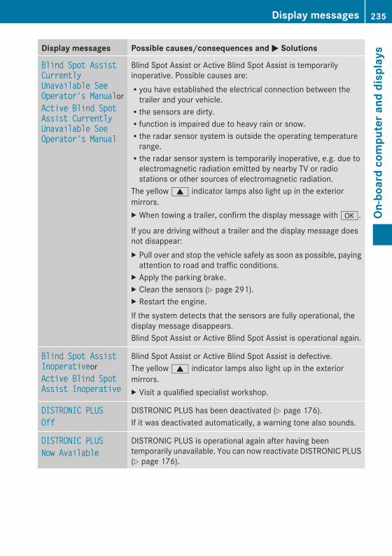
Display messages Possible causes/consequences andMM Solutions
Blind Spot AssistBlind Spot AssistCurrentlyCurrentlyUnavailable SeeUnavailable SeeOperator's ManualOperator's ManualorActive Blind SpotActive Blind SpotAssist CurrentlyAssist CurrentlyUnavailable SeeUnavailable SeeOperator's ManualOperator's Manual
Blind Spot Assist or Active Blind Spot Assist is temporarilyinoperative. Possible causes are:Ryou have established the electrical connection between thetrailer and your vehicle.Rthe sensors are dirty.Rfunction is impaired due to heavy rain or snow.Rthe radar sensor system is outside the operating temperaturerange.Rthe radar sensor system is temporarily inoperative, e.g. due toelectromagnetic radiation emitted by nearby TV or radiostations or other sources of electromagnetic radiation.
The yellow9 indicator lamps also light up in the exteriormirrors.X When towing a trailer, confirm the display message witha.
If you are driving without a trailer and the display message doesnot disappear:X Pull over and stop the vehicle safely as soon as possible, payingattention to road and traffic conditions.
X Apply the parking brake.X Clean the sensors (Y page 291).X Restart the engine.If the system detects that the sensors are fully operational, thedisplay message disappears.Blind Spot Assist or Active Blind Spot Assist is operational again.
Blind Spot AssistBlind Spot AssistInoperativeInoperativeorActive Blind SpotActive Blind SpotAssist InoperativeAssist Inoperative
Blind Spot Assist or Active Blind Spot Assist is defective.The yellow9 indicator lamps also light up in the exteriormirrors.X Visit a qualified specialist workshop.
DISTRONIC PLUSDISTRONIC PLUSOffOff
DISTRONIC PLUS has been deactivated (Y page 176).If it was deactivated automatically, a warning tone also sounds.
DISTRONIC PLUSDISTRONIC PLUSNow AvailableNow Available
DISTRONIC PLUS is operational again after having beentemporarily unavailable. You can now reactivate DISTRONIC PLUS(Y page 176).
Display messages 235
On-board
computerand
displays
Z
Display messages Possible causes/consequences andMM Solutions
DISTRONIC PLUSDISTRONIC PLUSCurrentlyCurrentlyUnavailable SeeUnavailable SeeOperator's ManualOperator's Manual
DISTRONIC is deactivated and temporarily inoperative. Possiblecauses are:Rthe DISTRONIC PLUS cover in the radiator trim is dirtyRfunction is impaired due to heavy rain or snow.Rthe sensors in the bumpers are dirty.Rthe radar sensor system is temporarily inoperative, e.g. due toelectromagnetic radiation emitted by nearby TV or radiostations or other sources of electromagnetic radiation.Rthe system is outside the operating temperature range.Rthe transfer case is in the LOW RANGE transmission position.Rthe vehicle is on an uphill or downhill gradient of greater than22%-25%.Rthe on-board voltage is too low.A warning tone also sounds.If the display message does not disappear:X Pull over and stop the vehicle safely as soon as possible, payingattention to road and traffic conditions.
X Apply the parking brake.X Clean the DISTRONIC PLUS cover in the radiator trim and thebumper (Y page 291).
X Restart the engine.If the system detects that the sensors are fully operational, thedisplay message disappears.DISTRONIC is operational again.
DISTRONIC PLUSDISTRONIC PLUSInoperativeInoperative
DISTRONIC PLUS is defective.BAS (Brake Assist) may also have failed.A warning tone also sounds.X Visit a qualified specialist workshop.
DISTRONIC PLUSDISTRONIC PLUSPassivePassive
You have depressed the accelerator pedal. DISTRONIC PLUS is nolonger controlling the speed of the vehicle.X Remove your foot from the accelerator pedal.
DISTRONIC PLUSDISTRONIC PLUS--- mph--- mph
An activation condition for DISTRONIC PLUS is not fulfilled.X Check the activation conditions for DISTRONIC PLUS(Y page 176).
DISTRONICDISTRONIC PLUSPLUS andandSPEEDTRONICSPEEDTRONICInoperativeInoperative
DISTRONIC PLUS and SPEEDTRONIC are faulty. A warning tonealso sounds.X Visit a qualified specialist workshop.
236 Display messagesOn
-board
computerand
displays
Display messages Possible causes/consequences andMM Solutions
CruiseCruise ControlControl andandSPEEDTRONICSPEEDTRONICInoperativeInoperative
Cruise control and SPEEDTRONIC are malfunctioning.X Visit a qualified specialist workshop.
LimitLimit--- mph--- mph
While depressing the accelerator pedal beyond the pressure point(kickdown), SPEEDTRONIC cannot be activated.
Cruise ControlCruise Control--- mph--- mph
A condition for activating cruise control has not been fulfilled.You have tried to store a speed below 20 mph (30 km/h), forexample.X If conditions permit, drive faster than 20 mph (30 km/h) andstore the speed.
X Check the activation conditions for cruise control(Y page 168).
Tires
Display messages Possible causes/consequences andMM Solutions
TireTire pressurepressure willwillbebe displayeddisplayed afterafterdriving a fewdriving a fewminutesminutes
The tire pressure monitor is measuring the tire pressure.X Drive on.The tire pressures appear in the multifunction display after youhave been driving for a few minutes.
Tire Press.Tire Press.MonitorMonitorInoperativeInoperative
The tire pressure monitor is faulty.X Visit a qualified specialist workshop.
Tire PressureTire PressureMonitorMonitorInoperative NoInoperative NoWheel SensorsWheel Sensors
The wheels mounted do not have a suitable tire pressure sensor.The tire pressure monitor is deactivated.X Mount wheels with suitable tire pressure sensors.The tire pressuremonitor is activated automatically after drivingfor a few minutes.
Display messages 237
On-board
computerand
displays
Z
Display messages Possible causes/consequences andMM Solutions
Check TiresCheck Tires The tire pressure in one or more tires has dropped significantly.The wheel position is displayed in the multifunction display.A warning tone also sounds.
G WARNINGWith tire pressures which are too low, there is a risk of thefollowing hazards:Rthey may burst, especially as the load and vehicle speedincrease.Rthey may wear excessively and/or unevenly, which may greatlyimpair tire traction.Rthe driving characteristics, as well as steering and braking, maybe greatly impaired.
There is a risk of an accident.X Stop the vehicle without making any sudden steering or brakingmaneuvers. Pay attention to the traffic conditions as you do so.
X Secure the vehicle against rolling away (Y page 156).X If there is a flat tire, inspect the tires (Y page 298).X Check the tire pressure (Y page 319).X If necessary, correct the tire pressure.
Warning TireWarning TireMalfunctionMalfunction
The tire pressure in one or more tires has dropped suddenly. Thewheel position is shown in the multifunction display.
G WARNINGIf you drive with a flat tire, there is a risk of the following hazards:RA flat tire affects the ability to steer or brake the vehicle.RYou could lose control of the vehicle.RContinued driving with a flat tire will cause excessive heat build-up and possibly a fire.
There is a risk of an accident.X Stop the vehicle without making any sudden steering or brakingmaneuvers. Pay attention to the traffic conditions as you do so.
X Secure the vehicle against rolling away (Y page 156).X If there is a flat tire, inspect the tires (Y page 298).
Correct TireCorrect TirePressurePressure
The tire pressure is too low in at least one of the tires, or the tirepressure difference between the wheels is too great.X Check the tire pressures at the next opportunity (Y page 319).X If necessary, correct the tire pressure.X Restart the tire pressure monitor (Y page 321).
238 Display messagesOn
-board
computerand
displays
Display messages Possible causes/consequences andMM Solutions
TirePress.TirePress.Sensor(s) MissingSensor(s) Missing
There is no signal from the tire pressure sensor of one or severalwheels. The pressure of the affected tire is not displayed in themultifunction display.X Have the faulty tire pressure sensor replaced at a qualifiedspecialist workshop.
Tire Press.Tire Press.Monitor CurrentlyMonitor CurrentlyUnavailableUnavailable
Due to a source of radio interference, no signals can be receivedfrom the wheel sensors. The tire pressure monitor is temporarilymalfunctioning.X Drive on.The tire pressure monitor restarts automatically as soon as theproblem has been solved.
hTire PressureTire PressureWarning TireWarning TireFailureFailure
The tire pressure in one or more tires has dropped suddenly.A warning tone also sounds.
G WARNINGIf you drive with a flat tire, there is a risk of the following hazards:RA flat tire affects the ability to steer or brake the vehicle.RYou could lose control of the vehicle.RContinued driving with a flat tire will cause excessive heat build-up and possibly a fire.There is a risk of an accident.
X Stop the vehicle without making any sudden steering or brakingmaneuvers. Pay attention to the traffic conditions as you do so.
X Secure the vehicle against rolling away (Y page 156).X If there is a flat tire, inspect the tires (Y page 298).
Display messages 239
On-board
computerand
displays
Z
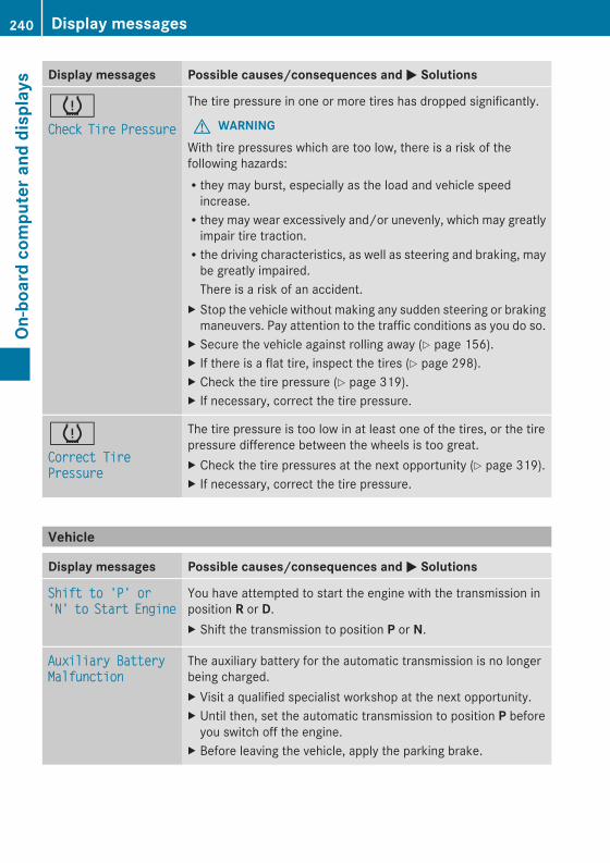
Display messages Possible causes/consequences andMM Solutions
hCheckCheck TireTire PressurePressure
The tire pressure in one or more tires has dropped significantly.
G WARNINGWith tire pressures which are too low, there is a risk of thefollowing hazards:Rthey may burst, especially as the load and vehicle speedincrease.Rthey may wear excessively and/or unevenly, which may greatlyimpair tire traction.Rthe driving characteristics, as well as steering and braking, maybe greatly impaired.There is a risk of an accident.
X Stop the vehicle without making any sudden steering or brakingmaneuvers. Pay attention to the traffic conditions as you do so.
X Secure the vehicle against rolling away (Y page 156).X If there is a flat tire, inspect the tires (Y page 298).X Check the tire pressure (Y page 319).X If necessary, correct the tire pressure.
hCorrect TireCorrect TirePressurePressure
The tire pressure is too low in at least one of the tires, or the tirepressure difference between the wheels is too great.X Check the tire pressures at the next opportunity (Y page 319).X If necessary, correct the tire pressure.
Vehicle
Display messages Possible causes/consequences andMM Solutions
Shift to 'P' orShift to 'P' or'N''N' toto StartStart EngineEngine
You have attempted to start the engine with the transmission inposition R or D.X Shift the transmission to position P or N.
Auxiliary BatteryAuxiliary BatteryMalfunctionMalfunction
The auxiliary battery for the automatic transmission is no longerbeing charged.X Visit a qualified specialist workshop at the next opportunity.X Until then, set the automatic transmission to position P beforeyou switch off the engine.
X Before leaving the vehicle, apply the parking brake.
240 Display messagesOn
-board
computerand
displays
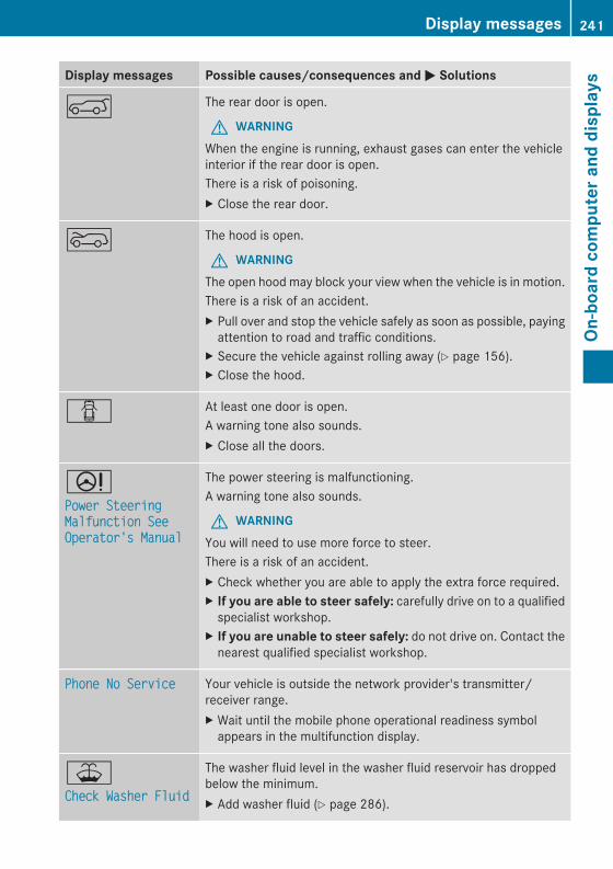
Display messages Possible causes/consequences andMM Solutions
A The rear door is open.
G WARNINGWhen the engine is running, exhaust gases can enter the vehicleinterior if the rear door is open.There is a risk of poisoning.X Close the rear door.
? The hood is open.
G WARNINGThe open hood may block your view when the vehicle is in motion.There is a risk of an accident.X Pull over and stop the vehicle safely as soon as possible, payingattention to road and traffic conditions.
X Secure the vehicle against rolling away (Y page 156).X Close the hood.
C At least one door is open.A warning tone also sounds.X Close all the doors.
DPower SteeringPower SteeringMalfunction SeeMalfunction SeeOperator's ManualOperator's Manual
The power steering is malfunctioning.A warning tone also sounds.
G WARNINGYou will need to use more force to steer.There is a risk of an accident.X Check whether you are able to apply the extra force required.X If you are able to steer safely: carefully drive on to a qualifiedspecialist workshop.
X If you are unable to steer safely: do not drive on. Contact thenearest qualified specialist workshop.
Phone No ServicePhone No Service Your vehicle is outside the network provider's transmitter/receiver range.X Wait until the mobile phone operational readiness symbolappears in the multifunction display.
¥Check Washer FluidCheck Washer Fluid
The washer fluid level in the washer fluid reservoir has droppedbelow the minimum.X Add washer fluid (Y page 286).
Display messages 241
On-board
computerand
displays
Z
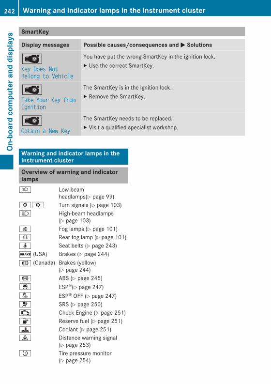
SmartKey
Display messages Possible causes/consequences andMM Solutions
ÂKey Does NotKey Does NotBelong to VehicleBelong to Vehicle
You have put the wrong SmartKey in the ignition lock.X Use the correct SmartKey.
ÂTakeTake YourYour KeyKey fromfromIgnitionIgnition
The SmartKey is in the ignition lock.X Remove the SmartKey.
ÂObtain a New KeyObtain a New Key
The SmartKey needs to be replaced.X Visit a qualified specialist workshop.
Warning and indicator lamps in theinstrument cluster
Overview of warning and indicatorlamps
L Low-beamheadlamps(Y page 99)
#! Turn signals (Y page 103)K High-beam headlamps
(Y page 103)N Fog lamps (Y page 101)R Rear fog lamp (Y page 101)ü Seat belts (Y page 243)$ (USA) Brakes (Y page 244)J (Canada) Brakes (yellow)
(Y page 244)! ABS (Y page 245)÷ ESP®(Y page 247)å ESP® OFF (Y page 247)6 SRS (Y page 250); Check Engine (Y page 251)8 Reserve fuel (Y page 251)? Coolant (Y page 251)· Distance warning signal
(Y page 253)h Tire pressure monitor
(Y page 254)
242 Warning and indicator lamps in the instrument clusterOn
-board
computerand
displays
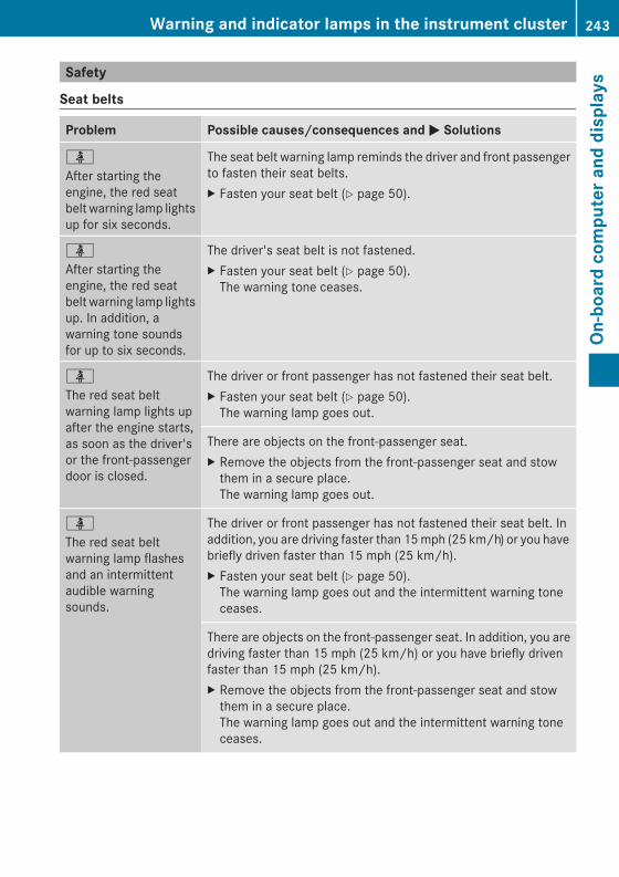
Safety
Seat belts
Problem Possible causes/consequences andMM Solutions
ü
After starting theengine, the red seatbelt warning lamp lightsup for six seconds.
The seat belt warning lamp reminds the driver and front passengerto fasten their seat belts.X Fasten your seat belt (Y page 50).
ü
After starting theengine, the red seatbelt warning lamp lightsup. In addition, awarning tone soundsfor up to six seconds.
The driver's seat belt is not fastened.X Fasten your seat belt (Y page 50).The warning tone ceases.
ü
The red seat beltwarning lamp lights upafter the engine starts,as soon as the driver'sor the front-passengerdoor is closed.
The driver or front passenger has not fastened their seat belt.X Fasten your seat belt (Y page 50).The warning lamp goes out.
There are objects on the front-passenger seat.X Remove the objects from the front-passenger seat and stowthem in a secure place.The warning lamp goes out.
ü
The red seat beltwarning lamp flashesand an intermittentaudible warningsounds.
The driver or front passenger has not fastened their seat belt. Inaddition, you are driving faster than 15mph (25 km/h) or you havebriefly driven faster than 15 mph (25 km/h).X Fasten your seat belt (Y page 50).The warning lamp goes out and the intermittent warning toneceases.
There are objects on the front-passenger seat. In addition, you aredriving faster than 15 mph (25 km/h) or you have briefly drivenfaster than 15 mph (25 km/h).X Remove the objects from the front-passenger seat and stowthem in a secure place.The warning lamp goes out and the intermittent warning toneceases.
Warning and indicator lamps in the instrument cluster 243
On-board
computerand
displays
Z
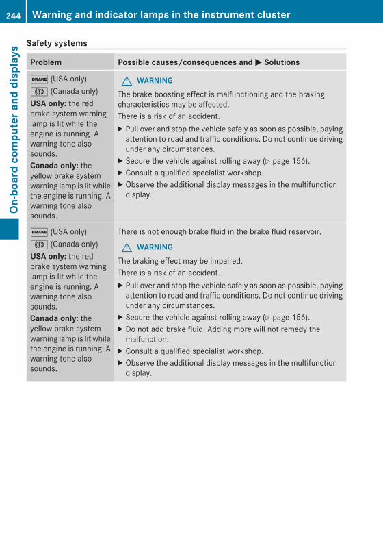
Safety systems
Problem Possible causes/consequences andMM Solutions
$ (USA only)J (Canada only)USA only: the redbrake system warninglamp is lit while theengine is running. Awarning tone alsosounds.Canada only: theyellow brake systemwarning lamp is lit whilethe engine is running. Awarning tone alsosounds.
G WARNINGThe brake boosting effect is malfunctioning and the brakingcharacteristics may be affected.There is a risk of an accident.X Pull over and stop the vehicle safely as soon as possible, payingattention to road and traffic conditions. Do not continue drivingunder any circumstances.
X Secure the vehicle against rolling away (Y page 156).X Consult a qualified specialist workshop.X Observe the additional display messages in the multifunctiondisplay.
$ (USA only)J (Canada only)USA only: the redbrake system warninglamp is lit while theengine is running. Awarning tone alsosounds.Canada only: theyellow brake systemwarning lamp is lit whilethe engine is running. Awarning tone alsosounds.
There is not enough brake fluid in the brake fluid reservoir.
G WARNINGThe braking effect may be impaired.There is a risk of an accident.X Pull over and stop the vehicle safely as soon as possible, payingattention to road and traffic conditions. Do not continue drivingunder any circumstances.
X Secure the vehicle against rolling away (Y page 156).X Do not add brake fluid. Adding more will not remedy themalfunction.
X Consult a qualified specialist workshop.X Observe the additional display messages in the multifunctiondisplay.
244 Warning and indicator lamps in the instrument clusterOn
-board
computerand
displays
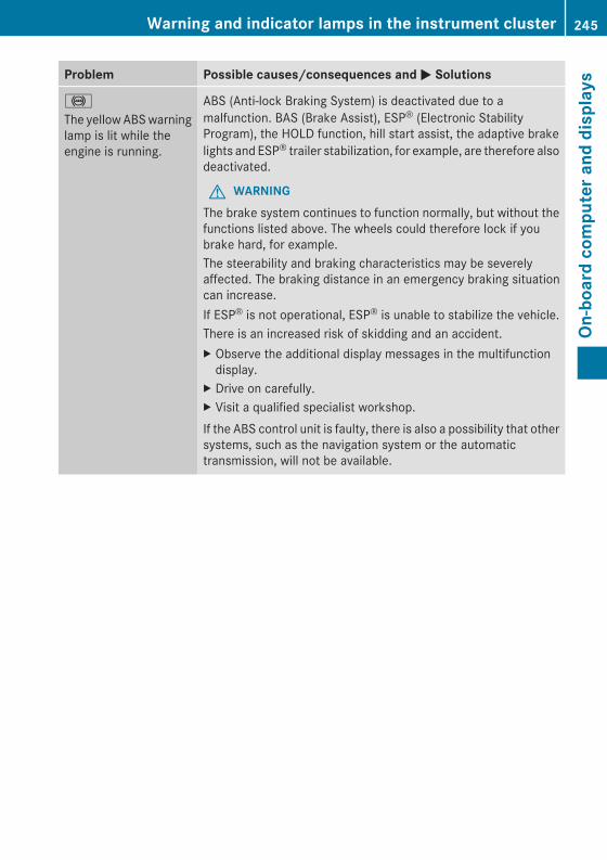
Problem Possible causes/consequences and MM Solutions
!
The yellowABSwarninglamp is lit while theengine is running.
ABS (Anti-lock Braking System) is deactivated due to amalfunction. BAS (Brake Assist), ESP® (Electronic StabilityProgram), the HOLD function, hill start assist, the adaptive brakelights and ESP® trailer stabilization, for example, are therefore alsodeactivated.
G WARNINGThe brake system continues to function normally, but without thefunctions listed above. The wheels could therefore lock if youbrake hard, for example.The steerability and braking characteristics may be severelyaffected. The braking distance in an emergency braking situationcan increase.If ESP® is not operational, ESP® is unable to stabilize the vehicle.There is an increased risk of skidding and an accident.X Observe the additional display messages in the multifunctiondisplay.
X Drive on carefully.X Visit a qualified specialist workshop.If the ABS control unit is faulty, there is also a possibility that othersystems, such as the navigation system or the automatictransmission, will not be available.
Warning and indicator lamps in the instrument cluster 245
On-board
computerand
displays
Z
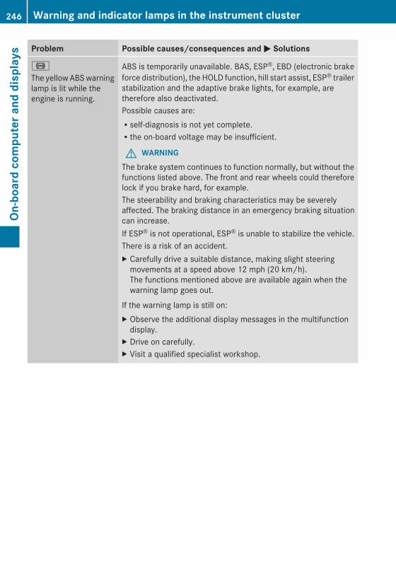
Problem Possible causes/consequences and MM Solutions
!
The yellowABSwarninglamp is lit while theengine is running.
ABS is temporarily unavailable. BAS, ESP®, EBD (electronic brakeforce distribution), the HOLD function, hill start assist, ESP® trailerstabilization and the adaptive brake lights, for example, aretherefore also deactivated.Possible causes are:Rself-diagnosis is not yet complete.Rthe on-board voltage may be insufficient.
G WARNINGThe brake system continues to function normally, but without thefunctions listed above. The front and rear wheels could thereforelock if you brake hard, for example.The steerability and braking characteristics may be severelyaffected. The braking distance in an emergency braking situationcan increase.If ESP® is not operational, ESP® is unable to stabilize the vehicle.There is a risk of an accident.X Carefully drive a suitable distance, making slight steeringmovements at a speed above 12 mph (20 km/h).The functions mentioned above are available again when thewarning lamp goes out.
If the warning lamp is still on:X Observe the additional display messages in the multifunctiondisplay.
X Drive on carefully.X Visit a qualified specialist workshop.
246 Warning and indicator lamps in the instrument clusterOn
-board
computerand
displays
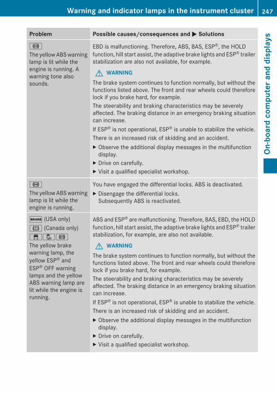
Problem Possible causes/consequences and MM Solutions
!
The yellowABSwarninglamp is lit while theengine is running. Awarning tone alsosounds.
EBD is malfunctioning. Therefore, ABS, BAS, ESP®, the HOLDfunction, hill start assist, the adaptive brake lights and ESP® trailerstabilization are also not available, for example.
G WARNINGThe brake system continues to function normally, but without thefunctions listed above. The front and rear wheels could thereforelock if you brake hard, for example.The steerability and braking characteristics may be severelyaffected. The braking distance in an emergency braking situationcan increase.If ESP® is not operational, ESP® is unable to stabilize the vehicle.There is an increased risk of skidding and an accident.X Observe the additional display messages in the multifunctiondisplay.
X Drive on carefully.X Visit a qualified specialist workshop.
!
The yellowABSwarninglamp is lit while theengine is running.
You have engaged the differential locks. ABS is deactivated.X Disengage the differential locks.Subsequently ABS is reactivated.
$ (USA only)J (Canada only)֌!
The yellow brakewarning lamp, theyellow ESP® andESP® OFF warninglamps and the yellowABS warning lamp arelit while the engine isrunning.
ABS and ESP® aremalfunctioning. Therefore, BAS, EBD, the HOLDfunction, hill start assist, the adaptive brake lights and ESP® trailerstabilization, for example, are also not available.
G WARNINGThe brake system continues to function normally, but without thefunctions listed above. The front and rear wheels could thereforelock if you brake hard, for example.The steerability and braking characteristics may be severelyaffected. The braking distance in an emergency braking situationcan increase.If ESP® is not operational, ESP® is unable to stabilize the vehicle.There is an increased risk of skidding and an accident.X Observe the additional display messages in the multifunctiondisplay.
X Drive on carefully.X Visit a qualified specialist workshop.
Warning and indicator lamps in the instrument cluster 247
On-board
computerand
displays
Z
Problem Possible causes/consequences and MM Solutions
÷
The yellow ESP®warning lamp flasheswhile the vehicle is inmotion.
ESP® or traction control has intervened because there is a risk ofskidding or at least one wheel has started to spin.Cruise control or DISTRONIC PLUS is deactivated.X When pulling away, only depress the accelerator pedal as far asnecessary.
X Ease off the accelerator pedal while the vehicle is in motion.X Adapt your driving style to suit the road and weather conditions.X Do not deactivate ESP®.For exceptions, see: (Y page 62).
å
The yellow ESP® OFFwarning lamp is lit whilethe engine is running.
ESP® is deactivated.
G WARNING
If ESP® is switched off, ESP® is unable to stabilize the vehicle.There is an increased risk of skidding and an accident.X Reactivate ESP®.For exceptions, see: (Y page 62).
X Adapt your driving style to suit the road and weather conditions.
If ESP® cannot be activated:X Have ESP® checked at a qualified specialist workshop.
֌
The yellow ESP® andESP® OFF warninglamps are lit while theengine is running.
ESP®, BAS, the HOLD function, hill start assist, the adaptive brakelights and ESP® trailer stabilization are not available due to amalfunction.
G WARNINGThe brake system continues to function normally, but without thefunctions listed above.The braking distance in an emergency braking situation can thusincrease.If ESP® is not operational, ESP® is unable to stabilize the vehicle.There is an increased risk of skidding and an accident.X Observe the additional display messages in the multifunctiondisplay.
X Drive on carefully.X Visit a qualified specialist workshop.
248 Warning and indicator lamps in the instrument clusterOn
-board
computerand
displays
Problem Possible causes/consequences and MM Solutions
֌
The yellow ESP® andESP® OFF warninglamps are lit while theengine is running.
ESP®, BAS, the HOLD function, hill start assist and ESP® trailerstabilization are temporarily unavailable.BAS and the adaptive brake lights may also have failed.Self-diagnosis is not yet complete.
G WARNINGThe brake system continues to function normally, but without thefunctions listed above.The braking distance in an emergency braking situation can thusincrease.If ESP® is not operational, ESP® is unable to stabilize the vehicle.There is an increased risk of skidding and an accident.X Carefully drive a suitable distance, making slight steeringmovements at a speed above 12 mph (20 km/h).The functions mentioned above are available again when thewarning lamp goes out.
If the warning lamp is still on:X Observe the additional display messages in the multifunctiondisplay.
X Drive on carefully.X Visit a qualified specialist workshop.
å
The yellow ESP® OFFwarning lamp is lit whilethe engine is running.
You have engaged the differential locks. ABS, ESP®, 4ETS and BAShave been deactivated.X Disengage the differential locks.ESP®, 4ETS and BAS are subsequently reactivated.
X Observe the additional display messages in the multifunctiondisplay.
Warning and indicator lamps in the instrument cluster 249
On-board
computerand
displays
Z
Problem Possible causes/consequences and MM Solutions
(Canada only)(USA only)The red parking brakewarning lamp comes onwhile the vehicle ismoving. A warning tonealso sounds.
You are driving with the parking brake applied.X Release the parking brake.The warning lamp goes out and the warning tone ceases.
6
The red SRS warninglamp is lit while theengine is running.
There is a malfunction in the SRS (Supplemental RestraintSystem).
G WARNINGThe air bags or Emergency Tensioning Devices may either betriggered unintentionally or, in the event of an accident, may notbe triggered.There is an increased risk of injury.X Drive on carefully.X Have SRS checked at a qualified specialist workshopimmediately.
For further information about SRS, see (Y page 39).
250 Warning and indicator lamps in the instrument clusterOn
-board
computerand
displays
Engine
Problem Possible causes/consequences andMM Solutions
;
The yellow CheckEngine warning lamplights up while theengine is running.
There may be a malfunction, for example:Rin the engine managementRin the fuel injection systemRin the exhaust systemRin the ignition systemRin the fuel systemThe emission limit values may be exceeded and the engine maybe in emergency mode.X Have the vehicle checked as soon as possible at a qualifiedspecialist workshop.
i In some states, you must immediately visit a qualifiedspecialist workshop as soon as the yellowCheck Enginewarninglamp lights up. This is due to the legal requirements in effect inthese states. If in doubt, check whether such legal regulationsapply in the state in which you are currently driving.
8
The yellow reserve fuelwarning lamp lights upwhile the engine isrunning.
The fuel level has dropped into the reserve range.X Refuel at the nearest gas station.
8
The yellow reserve fuelwarning lamp flasheswhile the vehicle is inmotion.In addition, the;Check Engine warninglamp may light up.
The fuel system pressure is too low. The fuel filler cap is not closedcorrectly or the fuel system is leaking.X Check that the fuel filler cap is correctly closed.X If the fuel filler cap is not correctly closed: close the fuel fillercap.
X If the fuel filler cap is closed: visit a qualified specialistworkshop.
?
The red coolantwarning lamp lights upwhile the engine isrunning and the coolanttemperature gauge isat the start of the scale.
The temperature sensor for the coolant temperature gauge isdefective.The coolant temperature is no longer being monitored. There is arisk of engine damage if the coolant temperature is too high.X Pull over and stop the vehicle safely and switch off the engine,paying attention to road and traffic conditions. Do not continuedriving under any circumstances.
X Apply the parking brake.X Consult a qualified specialist workshop.
Warning and indicator lamps in the instrument cluster 251
On-board
computerand
displays
Z
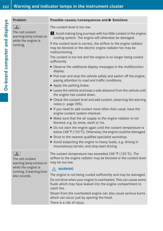
Problem Possible causes/consequences and MM Solutions
?
The red coolantwarning lamp comes onwhile the engine isrunning.
The coolant level is too low.
! Avoidmaking long journeys with too little coolant in the enginecooling system. The engine will otherwise be damaged.
If the coolant level is correct, the airflow to the engine radiatormay be blocked or the electric engine radiator fan may bemalfunctioning.The coolant is too hot and the engine is no longer being cooledsufficiently.X Observe the additional display messages in the multifunctiondisplay.
X Pull over and stop the vehicle safely and switch off the engine,paying attention to road and traffic conditions.
X Apply the parking brake.X Leave the vehicle and keep a safe distance from the vehicle untilthe engine has cooled down.
X Check the coolant level and add coolant, observing the warningnotes (Y page 285).
X If you need to add coolant more often than usual, have theengine coolant system checked.
X Make sure that the air supply to the engine radiator is notblocked, e.g. by snow, slush or ice.
X Do not start the engine again until the coolant temperature isbelow248‡ (120†). Otherwise, the engine could be damaged.
X Drive to the nearest qualified specialist workshop.X Avoid subjecting the engine to heavy loads, e.g. driving inmountainous terrain, and stop-start driving.
?
The red coolantwarning lamp comes onwhile the engine isrunning. Awarning tonealso sounds.
The coolant temperature has exceeded 248 ‡ (120 †). Theairflow to the engine radiator may be blocked or the coolant levelmay be too low.
G WARNINGThe engine is not being cooled sufficiently and may be damaged.Do not drive when your engine is overheated. This can cause somefluids which may have leaked into the engine compartment tocatch fire.Steam from the overheated engine can also cause serious burnswhich can occur just by opening the hood.There is a risk of injury.
252 Warning and indicator lamps in the instrument clusterOn
-board
computerand
displays
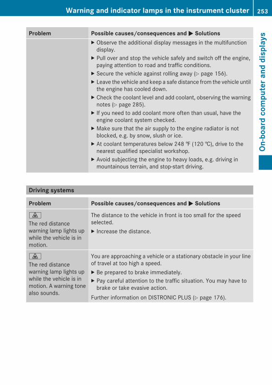
Problem Possible causes/consequences and MM SolutionsX Observe the additional display messages in the multifunctiondisplay.
X Pull over and stop the vehicle safely and switch off the engine,paying attention to road and traffic conditions.
X Secure the vehicle against rolling away (Y page 156).X Leave the vehicle and keep a safe distance from the vehicle untilthe engine has cooled down.
X Check the coolant level and add coolant, observing the warningnotes (Y page 285).
X If you need to add coolant more often than usual, have theengine coolant system checked.
X Make sure that the air supply to the engine radiator is notblocked, e.g. by snow, slush or ice.
X At coolant temperatures below 248 ‡ (120 †), drive to thenearest qualified specialist workshop.
X Avoid subjecting the engine to heavy loads, e.g. driving inmountainous terrain, and stop-start driving.
Driving systems
Problem Possible causes/consequences and MM Solutions
·
The red distancewarning lamp lights upwhile the vehicle is inmotion.
The distance to the vehicle in front is too small for the speedselected.X Increase the distance.
·
The red distancewarning lamp lights upwhile the vehicle is inmotion. A warning tonealso sounds.
You are approaching a vehicle or a stationary obstacle in your lineof travel at too high a speed.X Be prepared to brake immediately.X Pay careful attention to the traffic situation. You may have tobrake or take evasive action.
Further information on DISTRONIC PLUS (Y page 176).
Warning and indicator lamps in the instrument cluster 253
On-board
computerand
displays
Z
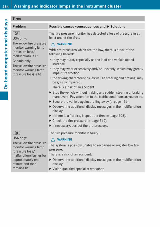
Tires
Problem Possible causes/consequences and MM Solutions
h
USA only:The yellow tire pressuremonitor warning lamp(pressure loss/malfunction) is lit.Canada only:The yellow tire pressuremonitor warning lamp(pressure loss) is lit.
The tire pressure monitor has detected a loss of pressure in atleast one of the tires.
G WARNINGWith tire pressures which are too low, there is a risk of thefollowing hazards:Rthey may burst, especially as the load and vehicle speedincrease.Rthey may wear excessively and/or unevenly, which may greatlyimpair tire traction.Rthe driving characteristics, as well as steering and braking, maybe greatly impaired.There is a risk of an accident.
X Stop the vehicle without making any sudden steering or brakingmaneuvers. Pay attention to the traffic conditions as you do so.
X Secure the vehicle against rolling away (Y page 156).X Observe the additional display messages in the multifunctiondisplay.
X If there is a flat tire, inspect the tires (Y page 298).X Check the tire pressure (Y page 319).X If necessary, correct the tire pressure.
h
USA only:The yellow tire pressuremonitor warning lamp(pressure loss/malfunction) flashes forapproximately oneminute and thenremains lit.
The tire pressure monitor is faulty.
G WARNINGThe system is possibly unable to recognize or register low tirepressure.There is a risk of an accident.X Observe the additional display messages in the multifunctiondisplay.
X Visit a qualified specialist workshop.
254 Warning and indicator lamps in the instrument clusterOn
-board
computera
nddisplays
Useful information ............................ 256Loading guidelines ............................ 256Stowage areas .................................. 257Features ............................................. 262
255
Stow
ageandfeatures
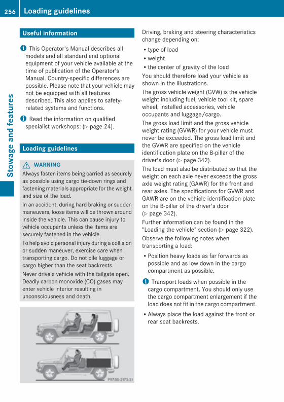
Useful information
i This Operator's Manual describes allmodels and all standard and optionalequipment of your vehicle available at thetime of publication of the Operator'sManual. Country-specific differences arepossible. Please note that your vehicle maynot be equipped with all featuresdescribed. This also applies to safety-related systems and functions.
i Read the information on qualifiedspecialist workshops: (Y page 24).
Loading guidelines
G WARNINGAlways fasten items being carried as securelyas possible using cargo tie-down rings andfasteningmaterials appropriate for the weightand size of the load.In an accident, during hard braking or suddenmaneuvers, loose itemswill be thrown aroundinside the vehicle. This can cause injury tovehicle occupants unless the items aresecurely fastened in the vehicle.To help avoid personal injury during a collisionor sudden maneuver, exercise care whentransporting cargo. Do not pile luggage orcargo higher than the seat backrests.Never drive a vehicle with the tailgate open.Deadly carbon monoxide (CO) gases mayenter vehicle interior resulting inunconsciousness and death.
Driving, braking and steering characteristicschange depending on:Rtype of loadRweightRthe center of gravity of the loadYou should therefore load your vehicle asshown in the illustrations.The gross vehicle weight (GVW) is the vehicleweight including fuel, vehicle tool kit, sparewheel, installed accessories, vehicleoccupants and luggage/cargo.The gross load limit and the gross vehicleweight rating (GVWR) for your vehicle mustnever be exceeded. The gross load limit andthe GVWR are specified on the vehicleidentification plate on the B-pillar of thedriver's door (Y page 342).The load must also be distributed so that theweight on each axle never exceeds the grossaxle weight rating (GAWR) for the front andrear axles. The specifications for GVWR andGAWR are on the vehicle identification plateon the B-pillar of the driver's door(Y page 342).Further information can be found in the"Loading the vehicle" section (Y page 322).Observe the following notes whentransporting a load:RPosition heavy loads as far forwards aspossible and as low down in the cargocompartment as possible.
i Transport loads when possible in thecargo compartment. You should only usethe cargo compartment enlargement if theload does not fit in the cargo compartment.RAlways place the load against the front orrear seat backrests.
256 Loading guidelinesStow
ageandfeatures
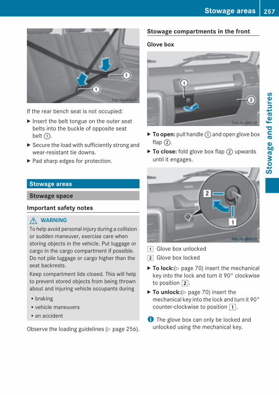
If the rear bench seat is not occupied:X Insert the belt tongue on the outer seatbelts into the buckle of opposite seatbelt:.
X Secure the load with sufficiently strong andwear-resistant tie downs.
X Pad sharp edges for protection.
Stowage areas
Stowage space
Important safety notes
G WARNINGTo help avoid personal injury during a collisionor sudden maneuver, exercise care whenstoring objects in the vehicle. Put luggage orcargo in the cargo compartment if possible.Do not pile luggage or cargo higher than theseat backrests.Keep compartment lids closed. This will helpto prevent stored objects from being thrownabout and injuring vehicle occupants duringRbrakingRvehicle maneuversRan accident
Observe the loading guidelines (Y page 256).
Stowage compartments in the front
Glove box
X Toopen: pull handle: and open glove boxflap;.
X To close: fold glove box flap; upwardsuntil it engages.
1 Glove box unlocked2 Glove box lockedX To lock:(Y page 70) insert the mechanicalkey into the lock and turn it 90° clockwiseto position2.
X To unlock:(Y page 70) insert themechanical key into the lock and turn it 90°counter-clockwise to position1.
i The glove box can only be locked andunlocked using the mechanical key.
Stowage areas 257
Stow
ageandfeatures
Z
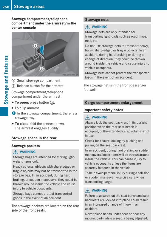
Stowage compartment/telephonecompartment under the armrest/in thecenter console
: Small stowage compartment; Release button for the armrest
Stowage compartment/telephonecompartment under the armrestX To open: press button;.X Fold up armrest.i In the stowage compartment, there is astowage tray.
X To close: fold the armrest down.The armrest engages audibly.
Stowage space in the rear
Stowage pocketsG WARNINGStorage bags are intended for storing light-weight items only.Heavy objects, objects with sharp edges orfragile objects may not be transported in thestorage bag. In an accident, during hardbraking, or sudden maneuvers, they could bethrown around inside the vehicle and causeinjury to vehicle occupants.Storage bags cannot protect transportedgoods in the event of an accident.
The stowage pockets are located on the rearside of the front seats.
Stowage nets
G WARNINGStowage nets are only intended fortransporting light loads such as road maps,mail, etc.Do not use stowage nets to transport heavy,bulky, sharp-edged or fragile objects. In anaccident, during hard braking or during achange of direction, they could be thrownaround inside the vehicle and cause injury tovehicle occupants.Stowage nets cannot protect the transportedloads in the event of an accident.
The stowage net is in the front-passengerfootwell.
Cargo compartment enlargement
Important safety notes
G WARNINGAlways lock the seat backrest in its uprightposition when the rear seat bench isoccupied, or the extended cargo volume is notin use.Check for secure locking by pushing andpulling on the seat backrest.In an accident, during hard braking or suddenmaneuvers, loose itemswill be thrown aroundinside the vehicle. This can cause injury tovehicle occupants unless the items aresecurely fastened in the vehicle.To help avoid personal injury during a collisionor sudden maneuver, exercise care whentransporting cargo.
G WARNINGFailure to assure that the seat bench and seatbackrests are locked into place could resultin an increased chance of injury in anaccident.Never place hands under seat or near anymoving parts while a seat is being adjusted.
258 Stowage areasStow
ageandfeatures
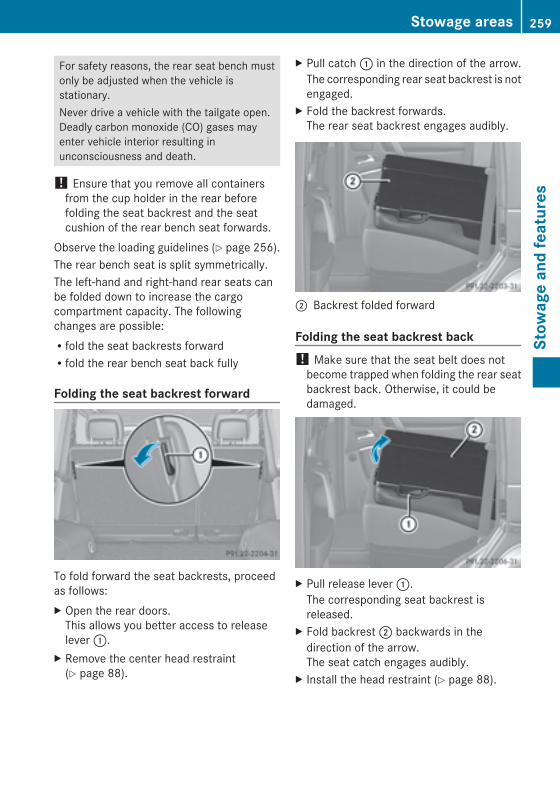
For safety reasons, the rear seat bench mustonly be adjusted when the vehicle isstationary.Never drive a vehicle with the tailgate open.Deadly carbon monoxide (CO) gases mayenter vehicle interior resulting inunconsciousness and death.
! Ensure that you remove all containersfrom the cup holder in the rear beforefolding the seat backrest and the seatcushion of the rear bench seat forwards.
Observe the loading guidelines (Y page 256).The rear bench seat is split symmetrically.The left-hand and right-hand rear seats canbe folded down to increase the cargocompartment capacity. The followingchanges are possible:Rfold the seat backrests forwardRfold the rear bench seat back fully
Folding the seat backrest forward
To fold forward the seat backrests, proceedas follows:X Open the rear doors.This allows you better access to releaselever:.
X Remove the center head restraint(Y page 88).
X Pull catch: in the direction of the arrow.The corresponding rear seat backrest is notengaged.
X Fold the backrest forwards.The rear seat backrest engages audibly.
; Backrest folded forward
Folding the seat backrest back! Make sure that the seat belt does notbecome trapped when folding the rear seatbackrest back. Otherwise, it could bedamaged.
X Pull release lever:.The corresponding seat backrest isreleased.
X Fold backrest; backwards in thedirection of the arrow.The seat catch engages audibly.
X Install the head restraint (Y page 88).
Stowage areas 259
Stow
ageandfeatures
Z
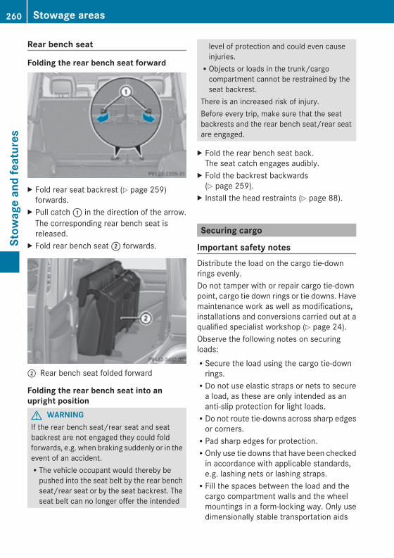
Rear bench seat
Folding the rear bench seat forward
X Fold rear seat backrest (Y page 259)forwards.
X Pull catch: in the direction of the arrow.The corresponding rear bench seat isreleased.
X Fold rear bench seat; forwards.
; Rear bench seat folded forward
Folding the rear bench seat into anupright positionG WARNINGIf the rear bench seat/rear seat and seatbackrest are not engaged they could foldforwards, e.g. when braking suddenly or in theevent of an accident.RThe vehicle occupant would thereby bepushed into the seat belt by the rear benchseat/rear seat or by the seat backrest. Theseat belt can no longer offer the intended
level of protection and could even causeinjuries.RObjects or loads in the trunk/cargocompartment cannot be restrained by theseat backrest.
There is an increased risk of injury.Before every trip, make sure that the seatbackrests and the rear bench seat/rear seatare engaged.
X Fold the rear bench seat back.The seat catch engages audibly.
X Fold the backrest backwards(Y page 259).
X Install the head restraints (Y page 88).
Securing cargo
Important safety notesDistribute the load on the cargo tie-downrings evenly.Do not tamper with or repair cargo tie-downpoint, cargo tie down rings or tie downs. Havemaintenance work as well as modifications,installations and conversions carried out at aqualified specialist workshop (Y page 24).Observe the following notes on securingloads:RSecure the load using the cargo tie-downrings.RDo not use elastic straps or nets to securea load, as these are only intended as ananti-slip protection for light loads.RDo not route tie-downs across sharp edgesor corners.RPad sharp edges for protection.ROnly use tie downs that have been checkedin accordance with applicable standards,e.g. lashing nets or lashing straps.RFill the spaces between the load and thecargo compartment walls and the wheelmountings in a form-locking way. Only usedimensionally stable transportation aids
260 Stowage areasStow
ageandfeatures
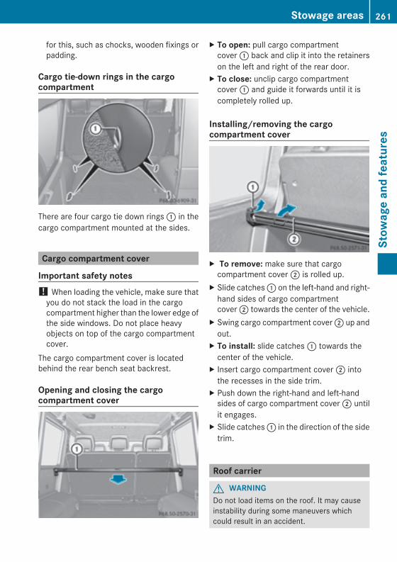
for this, such as chocks, wooden fixings orpadding.
Cargo tie-down rings in the cargocompartment
There are four cargo tie down rings: in thecargo compartment mounted at the sides.
Cargo compartment cover
Important safety notes! When loading the vehicle, make sure thatyou do not stack the load in the cargocompartment higher than the lower edge ofthe side windows. Do not place heavyobjects on top of the cargo compartmentcover.
The cargo compartment cover is locatedbehind the rear bench seat backrest.
Opening and closing the cargocompartment cover
X To open: pull cargo compartmentcover: back and clip it into the retainerson the left and right of the rear door.
X To close: unclip cargo compartmentcover: and guide it forwards until it iscompletely rolled up.
Installing/removing the cargocompartment cover
X To remove: make sure that cargocompartment cover; is rolled up.
X Slide catches: on the left-hand and right-hand sides of cargo compartmentcover; towards the center of the vehicle.
X Swing cargo compartment cover; up andout.
X To install: slide catches: towards thecenter of the vehicle.
X Insert cargo compartment cover; intothe recesses in the side trim.
X Push down the right-hand and left-handsides of cargo compartment cover; untilit engages.
X Slide catches: in the direction of the sidetrim.
Roof carrier
G WARNINGDo not load items on the roof. It may causeinstability during some maneuvers whichcould result in an accident.
Stowage areas 261
Stow
ageandfeatures
Z
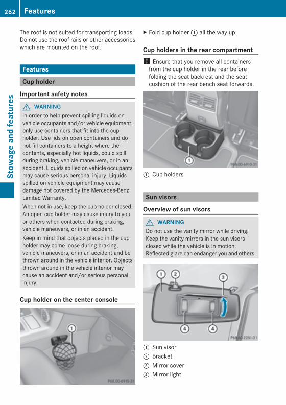
The roof is not suited for transporting loads.Do not use the roof rails or other accessorieswhich are mounted on the roof.
Features
Cup holder
Important safety notes
G WARNINGIn order to help prevent spilling liquids onvehicle occupants and/or vehicle equipment,only use containers that fit into the cupholder. Use lids on open containers and donot fill containers to a height where thecontents, especially hot liquids, could spillduring braking, vehicle maneuvers, or in anaccident. Liquids spilled on vehicle occupantsmay cause serious personal injury. Liquidsspilled on vehicle equipment may causedamage not covered by the Mercedes-BenzLimited Warranty.When not in use, keep the cup holder closed.An open cup holder may cause injury to youor others when contacted during braking,vehicle maneuvers, or in an accident.Keep in mind that objects placed in the cupholder may come loose during braking,vehicle maneuvers, or in an accident and bethrown around in the vehicle interior. Objectsthrown around in the vehicle interior maycause an accident and/or serious personalinjury.
Cup holder on the center console
X Fold cup holder: all the way up.
Cup holders in the rear compartment! Ensure that you remove all containersfrom the cup holder in the rear beforefolding the seat backrest and the seatcushion of the rear bench seat forwards.
: Cup holders
Sun visors
Overview of sun visors
G WARNINGDo not use the vanity mirror while driving.Keep the vanity mirrors in the sun visorsclosed while the vehicle is in motion.Reflected glare can endanger you and others.
: Sun visor; Bracket= Mirror cover? Mirror light
262 FeaturesStow
ageandfeatures
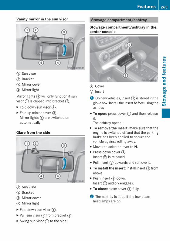
Vanity mirror in the sun visor
: Sun visor; Bracket= Mirror cover? Mirror light
Mirror lights? will only function if sunvisor: is clipped into bracket;.X Fold down sun visor:.X Fold up mirror cover=.Mirror lights? are switched onautomatically.
Glare from the side
: Sun visor; Bracket= Mirror cover? Mirror lightX Fold down sun visor:.X Pull sun visor: from bracket;.X Swing sun visor: to the side.
Stowage compartment/ashtray
Stowage compartment/ashtray in thecenter console
: Cover; Insert
i On new vehicles, insert; is stored in theglove box. Install the insert before using theashtray.
X To open: press cover: and then releaseit.The ashtray opens.
X To remove the insert:make sure that theengine is switched off and that the parkingbrake has been applied to secure thevehicle against rolling away.
X Move the selector lever to N.X Press down cover:.Insert; is released.
X Pull insert; upwards and remove it.X To install the insert: install insert; fromabove.
X Push insert; down.Insert; audibly engages.
X To close: close cover: fully.
i The ashtray is lit up if the low-beamheadlamps are on.
Features 263
Stow
ageandfeatures
Z
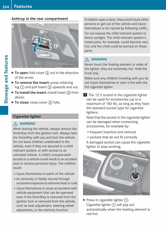
Ashtray in the rear compartment
X To open: fold cover; out in the directionof the arrow.
X To remove the insert: press retaininglug: and pull insert= upwards and out.
X To install the insert: install insert= fromabove.
X To close: close cover; fully.
Cigarette lighter
G WARNINGWhen leaving the vehicle, always remove theSmartKey from the ignition lock. Always takethe SmartKey with you and lock the vehicle.Do not leave children unattended in thevehicle, even if they are secured in a childrestraint system, or with access to anunlocked vehicle. A child's unsupervisedaccess to a vehicle could result in an accidentand/or serious personal injury. The childrencould:Rinjure themselves on parts of the vehicleRbe seriously or fatally injured throughexcessive exposure to extreme heat or coldRinjure themselves or cause an accidentwithvehicle equipment that can be operatedeven if the SmartKey is removed from theignition lock or removed from the vehicle,such as seat adjustment, steering wheeladjustment, or the memory function
If children open a door, they could injure otherpersons or get out of the vehicle and injurethemselves or be injured by following traffic.Do not expose the child restraint system todirect sunlight. The child restraint system'smetal parts, for example, could become veryhot, and the child could be burned on theseparts.
G WARNINGNever touch the heating element or sides ofthe lighter; they are extremely hot. Hold theknob only.Make sure any children traveling with you donot injure themselves or start a fire with thehot cigarette lighter.
! The 12 V socket in the cigarette lightercan be used for accessories (up to amaximum of 180 W), as long as they havethe standard socket type for cigarettelighters.Note that the socket in the cigarette lightercan be damaged when connectingaccessories, for example by:Rfrequent insertion and removalRsockets that do not fit correctlyA damaged socket can cause the cigarettelighter to stop working.
X Press in cigarette lighter:.Cigarette lighter: will pop outautomatically when the heating element isred-hot.
264 FeaturesStow
ageandfeatures
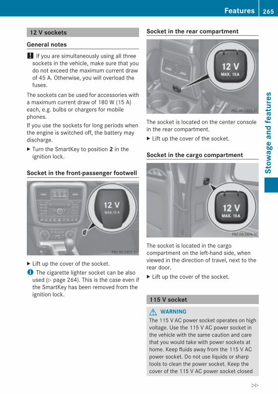
12 V sockets
General notes! If you are simultaneously using all threesockets in the vehicle, make sure that youdo not exceed the maximum current drawof 45 A. Otherwise, you will overload thefuses.
The sockets can be used for accessories witha maximum current draw of 180 W (15 A)each, e.g. bulbs or chargers for mobilephones.If you use the sockets for long periods whenthe engine is switched off, the battery maydischarge.X Turn the SmartKey to position 2 in theignition lock.
Socket in the front-passenger footwell
X Lift up the cover of the socket.i The cigarette lighter socket can be alsoused (Y page 264). This is the case even ifthe SmartKey has been removed from theignition lock.
Socket in the rear compartment
The socket is located on the center consolein the rear compartment.X Lift up the cover of the socket.
Socket in the cargo compartment
The socket is located in the cargocompartment on the left-hand side, whenviewed in the direction of travel, next to therear door.X Lift up the cover of the socket.
115 V socket
G WARNINGThe 115 V AC power socket operates on highvoltage. Use the 115 V AC power socket inthe vehicle with the same caution and carethat you would take with power sockets athome. Keep fluids away from the 115 V ACpower socket. Do not use liquids or sharptools to clean the power socket. Keep thecover of the 115 V AC power socket closed
Features 265
Stow
ageandfeatures
Z
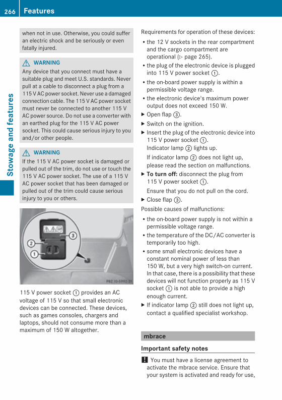
when not in use. Otherwise, you could sufferan electric shock and be seriously or evenfatally injured.
G WARNINGAny device that you connect must have asuitable plug and meet U.S. standards. Neverpull at a cable to disconnect a plug from a115VACpower socket. Never use a damagedconnection cable. The 115 V AC power socketmust never be connected to another 115 VAC power source. Do not use a converter withan earthed plug for the 115 V AC powersocket. This could cause serious injury to youand/or other people.
G WARNINGIf the 115 V AC power socket is damaged orpulled out of the trim, do not use or touch the115 V AC power socket. The use of a 115 VAC power socket that has been damaged orpulled out of the trim could cause seriousinjury to you or others.
115 V power socket: provides an ACvoltage of 115 V so that small electronicdevices can be connected. These devices,such as games consoles, chargers andlaptops, should not consume more than amaximum of 150 W altogether.
Requirements for operation of these devices:Rthe 12 V sockets in the rear compartmentand the cargo compartment areoperational (Y page 265).Rthe plug of the electronic device is pluggedinto 115 V power socket:.Rthe on-board power supply is within apermissible voltage range.Rthe electronic device's maximum poweroutput does not exceed 150 W.
X Open flap=.X Switch on the ignition.X Insert the plug of the electronic device into115 V power socket:.Indicator lamp; lights up.If indicator lamp; does not light up,please read the section on malfunctions.
X To turn off: disconnect the plug from115 V power socket:.Ensure that you do not pull on the cord.
X Close flap=.Possible causes of malfunctions:Rthe on-board power supply is not within apermissible voltage range.Rthe temperature of the DC/AC converter istemporarily too high.Rsome small electronic devices have aconstant nominal power of less than150 W, but a very high switch-on current.In that case, there is a possibility that thesedevices will not function properly as 115 Vsocket: is not able to provide a highenough current.
X If indicator lamp; still does not light up,contact a qualified specialist workshop.
mbrace
Important safety notes! You must have a license agreement toactivate the mbrace service. Ensure thatyour system is activated and ready for use,
266 FeaturesStow
ageandfeatures
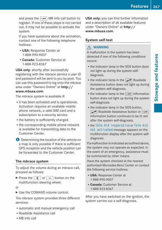
and press the E MB Info call button toregister. If one of these steps is not carriedout, it may not be possible to activate thesystem.If you have questions about the activation,contact one of the following telephonehotlines:RUSA: Response Center at1-888-990-9007RCanada: Customer Service at1-888-923-8367
USA only: shortly after successfullyregistering with the mbrace service a user IDand password will be sent to you by post. Youcan use this password to log onto the mbracearea under "Owners Online" at http://www.mbusa.com.The mbrace system is available if:Rit has been activated and is operational.Activation requires an available mobilephone network, a valid SIM card and asubscription to a security service.Rthe battery is sufficiently charged.Rthe corresponding mobile phone networkis available for transmitting data to theCustomer Center.
i Determining the location of the vehicle ona map is only possible if there is sufficientGPS reception and the vehicle position canbe forwarded to the Customer Center.
The mbrace systemTo adjust the volume during an mbrace call,proceed as follows:X Press theW orX button on themultifunction steering wheel.
orX Use the COMAND volume control.The mbrace system provides three differentservices:Rautomatic and manual emergency callRRoadside Assistance callRMB Info call
USA only: you can find further informationand a description of all available featuresunder "Owners Online" at http://www.mbusa.com.
System self-test
G WARNINGA malfunction in the system has beendetected if one of the following conditionsoccurs:Rthe indicator lamp in the SOS button doesnot light up during the system self-diagnosis.Rthe indicator lamp in theº RoadsideAssistance button does not light up duringthe system self-diagnosis.Rthe indicator lamp in the E informationbutton does not light up during the systemself-diagnosis.Rthe indicator lamp in the SOS button,º Roadside Assistance button or Einformation button continues to be lit redafter the system self-diagnosis.Rthe TeleTele AidAid inoperativeinoperative or TeleTele AidAidnot activatednot activated message appears on themultifunction display after the system self-diagnosis.
If amalfunction is indicated as outlined above,the system may not operate as expected. Inthe event of an emergency, assistance mustbe summoned by other means.Have the system checked at the nearestauthorized Mercedes-Benz Center or contactthe following service hotlines:RUSA: Response Center at1-888-990-9007RCanada: Customer Service at1-888-923-8367
After you have switched on the ignition, thesystem carries out a self-diagnosis.
Features 267
Stow
ageandfeatures
Z
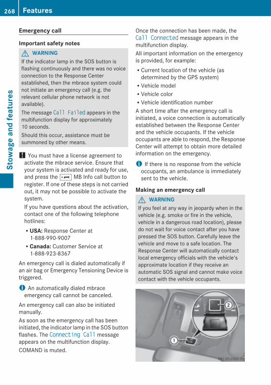
Emergency call
Important safety notesG WARNINGIf the indicator lamp in the SOS button isflashing continuously and there was no voiceconnection to the Response Centerestablished, then the mbrace system couldnot initiate an emergency call (e.g. therelevant cellular phone network is notavailable).The message Call FailedCall Failed appears in themultifunction display for approximately10 seconds.Should this occur, assistance must besummoned by other means.
! You must have a license agreement toactivate the mbrace service. Ensure thatyour system is activated and ready for use,and press the E MB Info call button toregister. If one of these steps is not carriedout, it may not be possible to activate thesystem.If you have questions about the activation,contact one of the following telephonehotlines:RUSA: Response Center at1-888-990-9007RCanada: Customer Service at1-888-923-8367
An emergency call is dialed automatically ifan air bag or Emergency Tensioning Device istriggered.
i An automatically dialed mbraceemergency call cannot be canceled.
An emergency call can also be initiatedmanually.As soon as the emergency call has beeninitiated, the indicator lamp in the SOS buttonflashes. The Connecting CallConnecting Call messageappears on the multifunction display.COMAND is muted.
Once the connection has been made, theCall ConnectedCall Connected message appears in themultifunction display.All important information on the emergencyis provided, for example:RCurrent location of the vehicle (asdetermined by the GPS system)RVehicle modelRVehicle colorRVehicle identification numberA short time after the emergency call isinitiated, a voice connection is automaticallyestablished between the Response Centerand the vehicle occupants. If the vehicleoccupants are able to respond, the ResponseCenter will attempt to obtain more detailedinformation on the emergency.
i If there is no response from the vehicleoccupants, an ambulance is immediatelysent to the vehicle.
Making an emergency callG WARNINGIf you feel at any way in jeopardy when in thevehicle (e.g. smoke or fire in the vehicle,vehicle in a dangerous road location), pleasedo not wait for voice contact after you havepressed the SOS button. Carefully leave thevehicle and move to a safe location. TheResponse Center will automatically contactlocal emergency officials with the vehicle'sapproximate location if they receive anautomatic SOS signal and cannot make voicecontact with the vehicle occupants.
268 FeaturesStow
ageandfeatures
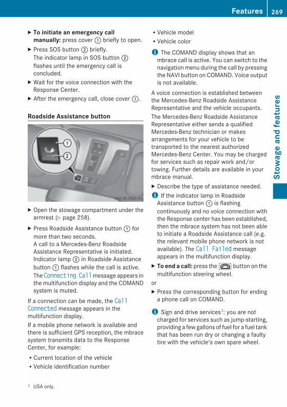
X To initiate an emergency callmanually: press cover: briefly to open.
X Press SOS button; briefly.The indicator lamp in SOS button;flashes until the emergency call isconcluded.
X Wait for the voice connection with theResponse Center.
X After the emergency call, close cover:.
Roadside Assistance button
X Open the stowage compartment under thearmrest (Y page 258).
X Press Roadside Assistance button: formore than two seconds.A call to a Mercedes-Benz RoadsideAssistance Representative is initiated.Indicator lamp; in Roadside Assistancebutton: flashes while the call is active.The ConnectingConnecting CallCallmessage appears inthe multifunction display and the COMANDsystem is muted.
If a connection can be made, the CallCallConnectedConnected message appears in themultifunction display.If a mobile phone network is available andthere is sufficient GPS reception, the mbracesystem transmits data to the ResponseCenter, for example:RCurrent location of the vehicleRVehicle identification number
RVehicle modelRVehicle color
i The COMAND display shows that anmbrace call is active. You can switch to thenavigationmenu during the call by pressingthe NAVI button on COMAND. Voice outputis not available.
A voice connection is established betweenthe Mercedes-Benz Roadside AssistanceRepresentative and the vehicle occupants.The Mercedes-Benz Roadside AssistanceRepresentative either sends a qualifiedMercedes-Benz technician or makesarrangements for your vehicle to betransported to the nearest authorizedMercedes-Benz Center. You may be chargedfor services such as repair work and/ortowing. Further details are available in yourmbrace manual.X Describe the type of assistance needed.i If the indicator lamp in RoadsideAssistance button: is flashingcontinuously and no voice connection withthe Response center has been established,then the mbrace system has not been ableto initiate a Roadside Assistance call (e.g.the relevant mobile phone network is notavailable). The Call FailedCall Failed messageappears in the multifunction display.
X To end a call: press the~ button on themultifunction steering wheel.
orX Press the corresponding button for endinga phone call on COMAND.
i Sign and drive services1: you are notcharged for services such as jump-starting,providing a few gallons of fuel for a fuel tankthat has been run dry or changing a faultytire with the vehicle's own spare wheel.
1 USA only.
Features 269
Stow
ageandfeatures
Z
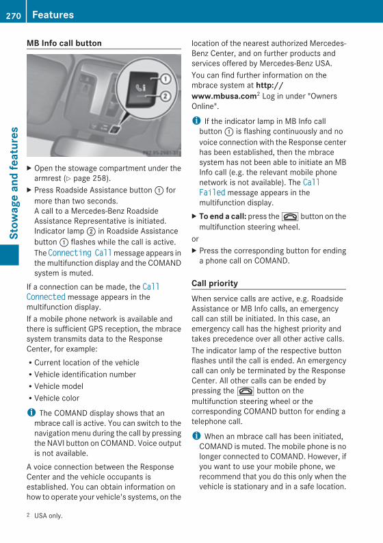
MB Info call button
X Open the stowage compartment under thearmrest (Y page 258).
X Press Roadside Assistance button: formore than two seconds.A call to a Mercedes-Benz RoadsideAssistance Representative is initiated.Indicator lamp; in Roadside Assistancebutton: flashes while the call is active.The ConnectingConnecting CallCallmessage appears inthe multifunction display and the COMANDsystem is muted.
If a connection can be made, the CallCallConnectedConnected message appears in themultifunction display.If a mobile phone network is available andthere is sufficient GPS reception, the mbracesystem transmits data to the ResponseCenter, for example:RCurrent location of the vehicleRVehicle identification numberRVehicle modelRVehicle color
i The COMAND display shows that anmbrace call is active. You can switch to thenavigationmenu during the call by pressingthe NAVI button on COMAND. Voice outputis not available.
A voice connection between the ResponseCenter and the vehicle occupants isestablished. You can obtain information onhow to operate your vehicle's systems, on the
location of the nearest authorized Mercedes-Benz Center, and on further products andservices offered by Mercedes-Benz USA.You can find further information on thembrace system at http://www.mbusa.com2 Log in under "OwnersOnline".
i If the indicator lamp in MB Info callbutton: is flashing continuously and novoice connection with the Response centerhas been established, then the mbracesystem has not been able to initiate an MBInfo call (e.g. the relevant mobile phonenetwork is not available). The CallCallFailedFailed message appears in themultifunction display.
X To end a call: press the~ button on themultifunction steering wheel.
orX Press the corresponding button for endinga phone call on COMAND.
Call priorityWhen service calls are active, e.g. RoadsideAssistance or MB Info calls, an emergencycall can still be initiated. In this case, anemergency call has the highest priority andtakes precedence over all other active calls.The indicator lamp of the respective buttonflashes until the call is ended. An emergencycall can only be terminated by the ResponseCenter. All other calls can be ended bypressing the~ button on themultifunction steering wheel or thecorresponding COMAND button for ending atelephone call.
i When an mbrace call has been initiated,COMAND is muted. The mobile phone is nolonger connected to COMAND. However, ifyou want to use your mobile phone, werecommend that you do this only when thevehicle is stationary and in a safe location.
2 USA only.
270 FeaturesStow
ageandfeatures
Downloading destinations in COMANDDestination Download gives you access to adatabase with over ten million points ofinterest (POIs) which can be downloaded ontothe navigation system of your vehicle. If youknow the destination, you can download theaddress or obtain the location of points ofinterest (POIs) or important destinations inthe surrounding area.You are prompted to confirm route guidanceto the address entered.i Information on the components andoperating principles of the COMANDsystem can be found in the separateCOMAND operating instructions.
X Select YesYes with the= or; buttonon COMAND.
X Confirm with the 9 button on COMAND.
The system calculates the route andsubsequently starts the route guidance withthe address entered.
i If you select NoNo, the address can be storedin the address book.
i The Destination Download function isavailable if the corresponding mobilephone network is available and datatransfer is possible.
Search & Send"Search & Send" is a destination entryservice. You can find further information on"Search & Send" in the separate COMANDoperating instructions.
Vehicle remote openingIf you have unintentionally locked yourvehicle (e.g. the SmartKey is inside thevehicle) and a replacement key is notavailable:X Contact the following service hotlines:
RUSA: Response Center at1-888-990-9007RCanada: Customer Service at1-888-923-8367
You will be asked for your password.X Return to your vehicle at the time arrangedwith the Response Center.
X Press the release button on the door handleof the rear door for at least 20 seconds untilthe indicator lamp in the SOS button(Y page 268) flashes.The Connecting CallConnecting Call message appearson the multifunction display.
Alternatively, the vehicle can be opened viathe Internet in the "Owner's Online" sectionusing your identification number andpassword3.
i Vehicle remote opening is only possible ifthe corresponding mobile phone networkis accessible.The SOS button flashes and theConnectingConnecting CallCallmessage appears in themultifunction display to confirm that thecommand for vehicle remote unlocking hasbeen received.If the lock cylinder on the rear door ispressed for longer than 20 seconds beforereceiving authorization for remoteunlocking from the Response center, youmust wait 15 minutes before you can pressthe lock cylinder on the rear door again.
Vehicle remote closingThe remote closing feature can be used whenyou have forgotten to lock the vehicle and youare no longer nearby. The vehicle can then belocked by the Mercedes-Benz CustomerAssistance Center.The vehicle can be remotely locked withinfour days of the ignition being turned off.X Contact the following service hotlines:
3 USA only.
Features 271
Stow
ageandfeatures
Z
RUSA: Mercedes-Benz CustomerAssistance Center at 1-800-FOR-MERCedes (1-800-367-6372) or1-888-990-9007RCanada: Customer Service at1-888-923-8367
You will be asked for your PIN.The next time you are inside the vehicle andyou switch on the ignition, the Tele AidTele AidDoors Locked RemotelyDoors Locked Remotely message appearsin the multifunction display.USA only: alternatively, the vehicle can belocked via:Rthe Internet, under the "Owners Online"sectionRthe telephone application (e.g. iPhone®,Blackberry)
To do this, you will need your identificationnumber and password.
i The vehicle remote closing feature isavailable when the relevant mobile phonenetwork is available and data connection ispossible.
Stolen vehicle recovery serviceIf your vehicle has been stolen:X Contact the police.The police will issue an incident report. Thisreport has a number.
X Forward this number to the ResponseCenter together with your PIN.The Response Center will then attempt tocovertly contact the mbrace system. TheResponse Center contacts you and thelocal law enforcement authority if thevehicle is located. However, only the lawenforcement agency is informed of thelocation of the vehicle.
i If the anti-theft alarm system is active forlonger than 30 seconds, mbrace isautomatically connected with theCustomer Assistance center.
Vehicle remote malfunction diagnosisWith the vehicle remote malfunctiondiagnosis (Vehicle Health Check), theCustomer Assistance center can provideimproved support for problems with yourvehicle. During an existing call, vehicle datais transferred to the Customer Assistancecenter. The customer service representativecan use the received data to decide what kindof assistance is required. You are then, forexample, guided to the nearest Mercedes-Benz Service center or a recovery vehicle iscalled.If vehicle data needs to be transferred duringan MB Info call or a Roadside Assistance call,this is initiated by the Customer Assistancecenter. You will see the RoadsideRoadsideAssistance ConnectedAssistance Connected message in theCOMAND display. If the vehicle remotemalfunction diagnosis is able to be started,the Request for vehicle diagnosisRequest for vehicle diagnosisreceived. Start vehicle diagnosis?received. Start vehicle diagnosis?message appears in the display.X Press YesYes to confirm the message.X If the Vehicle Diagnosis: PleaseVehicle Diagnosis: Pleasestart ignitionstart ignition message appears: turnthe SmartKey to position 2 in the ignitionlock.
X If the Please follow thePlease follow theinstructionsinstructions receivedreceived byby phonephone andandmove your vehicle into a safemove your vehicle into a safepositionposition message appears: follow theinstructions of the customer servicerepresentative.The message in the display disappears.If you select CancelCancel, the vehicle remotemalfunction diagnosis is canceledcompletely.The vehicle operating state check begins.Meanwhile, the Vehicle diagnosisVehicle diagnosisactivatedactivated message appears.
When the check is finished, the SendingSendingvehicle diagnosis data... (Voicevehicle diagnosis data... (Voiceconnection may be interruptedconnection may be interruptedduringduring datadata transfer)transfer)message appears.
272 FeaturesStow
ageandfeatures
The vehicle data can now be sent to theCustomer Assistance center.X Press OKOK to confirm the message.The voice connection with the CustomerAssistance center is terminated.The Vehicle Diagnosis:Vehicle Diagnosis:Transferring data...Transferring data... messageappears.The vehicle data is sent to the CustomerAssistance center.
Depending on what the customer servicerepresentative agreed with you, the voiceconnection is re-established after the transferis complete. If necessary, you will becontacted at a later time by another means,e.g. by e-mail or phone.Further functions of the vehicle remotemalfunction diagnosis include, for example:Rtransfer of service data to the CustomerAssistance center. If a service is overdue,the COMAND display shows a messageabout various special offers at yourworkshop.Rmonthly status information e-mail on oillevel, air pressure, maintenance, brakes,etc. If applicable, you will receiveinformation on special offers in the e-mail.USA only: this information can also becalled up under "Owners Online" at http://www.mbusa.com.
Information on the data stored in the vehicle(Y page 25).Information on Roadside Assistance(Y page 22).
Downloading routesDownloading routes allows you to transferand save predefined routes in the navigationsystem. To do this, an SD memory card mustbe inserted into the COMAND system. If noSD memory card is inserted, you must insertthe card into the card slot on the COMANDsystem before saving.A route can be prepared and sent either by acustomer service representative or via the
mbrace portal on the Internet. Each route caninclude up to 20way points. When a route hasbeen received by the navigation system, the'Route name' has been saved to'Route name' has been saved tomemory card. Do you want to startmemory card. Do you want to startroute guidance?route guidance? message appears on theCOMAND display. The route is saved to theSD memory card.X To start route guidance: select YesYes.An overview of the route is shown in thedisplay.i If you select NoNo, the saved route can becalled up later in the navigation menu.
X Select StartStart.Route guidance is started.
i Downloaded and saved data can be calledup again in COMAND. Further informationcan be found in the "COMAND", "Onlineand Internet services" and "Downloaddestination/route" sections.
Speed alertYou can define the upper speed limit, whichmust not be exceeded by the vehicle. If thisselected speed is exceeded by the vehicle, amessage will be sent to the CustomerAssistance center. The Customer Assistancecenter then forwards this information to you.You can select the way in which you receivethis information beforehand. Possible optionsinclude text message, e-mail or an automatedcall.The data which is sent to the CustomerAssistance center contains the followinginformation:Rthe location where the speed limit wasexceededRthe time at which the speed limit wasexceededRthe selected speed limit which wasexceeded
Features 273
Stow
ageandfeatures
Z
Geo fencingGeo fencing allows you to select areas whichthe vehicle should not enter or leave. You willbe informed if the vehicle crosses theboundaries of the selected areas. You canselect the way in which you receive thisinformation beforehand. Possible optionsinclude text message, e-mail or an automatedcall.The area can be determined as either a circleor a polygon with a maximum of ten corners.You can specify up to ten areassimultaneously. Different settings arepossible for each area.USA only: these settings can be called upunder "Owners Online" at http://www.mbusa.com.Alternatively, you can trigger an MB Info calland inform the customer servicerepresentative that you wish to activate geofencing.Currently inactive areas can be activated bytext message.
Triggering the vehicle alarmWith this function, you can trigger thevehicle's panic alarm via text message. Analarm sounds and the exterior lightingflashes. Depending on the setting, the panicalarm lasts five or ten seconds. Afterwards,the alarm switches off.
Brush guard (USA only)
G WARNINGThe brush guard is designed solely to enhancethe appearance of the vehicle and helpprotect grille and headlamps from minormishaps, either on or off road.Since the safety characteristics are limited inthe event of an accident, brush guard are notintended to prevent injury or damage in theevent of an accident. Also observe state andlocal regulations on installation and use.
Raise and lower the brush guard in an openspace with plenty of room.
i If you wish to remove the brush guard,contact a qualified specialist workshop.
Garage door opener
Important safety notes
G WARNINGBefore programming the integrated remotecontrol to a garage door opener or gateoperator, make sure people and objects areout of the way of the device to preventpotential harm or damage. Whenprogramming a garage door opener, the doormoves up or down. When programming a gateoperator, the gate opens or closes.Do not use the integrated remote control withany garage door opener that lacks safety stopand reverse features as required by U.S.federal safety standards (this includes anygarage door opener model manufacturedbefore April 1, 1982). A garage door thatcannot detect an object - signaling the doorto stop and reverse - does not meet currentU.S. federal safety standards.When programming a garage door opener,park vehicle outside the garage.Do not run the engine while programming theintegrated remote control. Inhalation ofexhaust gas is hazardous to your health. Allexhaust gas contains carbon monoxide (CO),and inhaling it can cause unconsciousnessand possible death. All exhaust gas containscarbon monoxide (CO), and inhaling it cancause unconsciousness and possible death.
You can use the HomeLink® garage dooropener integrated into the rear-viewmirror tooperate up to three different gate/garagedoor opener systems.
274 FeaturesStow
ageandfeatures
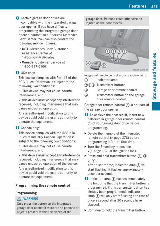
i Certain garage door drives areincompatible with the integrated garagedoor opener. If you have difficultyprogramming the integrated garage dooropener, contact an authorized Mercedes-Benz Center. You can also contact thefollowing service hotlines:RUSA: Mercedes-Benz CustomerAssistance Center at1-800-FOR-MERCedesRCanada: Customer Service at1-800-387-0100
i USA only:This device complies with Part 15 of theFCC Rules. Operation is subject to thefollowing two conditions:1. This device may not cause harmfulinterference, and2. this device must accept any interferencereceived, including interference that maycause undesired operation.Any unauthorized modification to thisdevice could void the user's authority tooperate the equipment.
i Canada only:This device complies with the RSS-210Rules of Industry Canada. Operation issubject to the following two conditions:1. This device may not cause harmfulinterference, and2. this device must accept any interferencereceived, including interference that maycause undesired operation of the device.Any unauthorized modification to thisdevice could void the user's authority tooperate the equipment.
Programming the remote control
ProgrammingG WARNINGOnly press the button on the integratedgarage door opener if there are no persons orobjects present within the sweep of the
garage door. Persons could otherwise beinjured as the door moves.
Integrated remote control in the rear-view mirror: Indicator lamp;=? Transmitter buttonsA Garage door remote controlB Transmitter button on the garage
door remote controlGarage door remote controlA is not part ofthe garage door opener.i To achieve the best result, insert newbatteries in garage door remote controlA of your garage door drive beforeprogramming.
X Delete the memory of the integratedremote control (Y page 278) beforeprogramming it for the first time.
X Turn the SmartKey to position2(Y page 139) in the ignition lock.
X Press and hold transmitter button;,=or?.After a short time, indicator lamp: willstart flashing. It flashes approximatelyonce per second.i Indicator lamp: flashes immediatelythe first time that the transmitter button isprogrammed. If this transmitter button hasalready been programmed, indicatorlamp: will only start flashing at a rate ofonce a second after 20 seconds haveelapsed.
X Continue to hold the transmitter button.
Features 275
Stow
ageandfeatures
Z
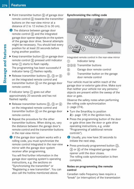
X Point transmitter buttonA of garage doorremote controlB towards the transmitterbuttons on the rear-view mirror at adistance of 2 to 12 inches (5 to 30 cm).i The distance between garage doorremote controlA and the integratedgarage door opener depends on the systemof the garage door drive. Several attemptsmight be necessary. You should test everyposition for at least 20 seconds beforetrying another position.
X Keep transmitter buttonB on garage doorremote controlA pressed until indicatorlamp: starts to flash rapidly.The programming has been successful ifindicator lamp: flashes rapidly.
X Release transmitter buttons;,= or?on the integrated remote control andtransmitter buttonB on the garage doorremote control.
If indicator lamp: goes out afterapproximately 20 seconds and has notflashed rapidly:X Release transmitter buttons;,= or?on the integrated remote control andtransmitter buttonB on the garage doorremote control.
X Repeat the procedure for the othertransmitter buttons. When doing so, varythe distance between the garage door'sremote control and the transmitter buttonsin the rear-view mirror.i If the garage door system works with arolling code, you must synchronize theremote control integrated in the rear-viewmirror with the garage door systemreceiver after programming.You will find further information in thegarage door opening system's operatinginstructions, e.g. the sections on"Synchronizing the transmitter" or"Registering a new transmitter". You canalso call the hotline mentioned above.
Synchronizing the rolling code
Integrated remote control in the rear-view mirror: Indicator lamp;=? Transmitter buttonsA Garage door remote controlB Transmitter button on the garage
door remote controlYour vehicle must be within reach of thegarage door or exterior gate drive. Make surethat neither your vehicle nor any persons/objects are present within the sweep of thedoor or gate.Observe the safety notes when performingthe rolling code synchronization(Y page 274).X Turn the SmartKey to position2(Y page 139) in the ignition lock.
X Press the programming button of the dooror gate drive (see the door or gate driveoperating instructions, e.g. under"Programming of additional remotecontrols").i Usually, you now have 30 seconds toinitiate the next step.
X Press previously programmed button;,= or? of the integrated garage dooropener until the door closes.The rolling code synchronization is thencomplete.
Notes on programming the remotecontrolCanadian radio frequency laws require a"break" (or interruption) of the transmission
276 FeaturesStow
ageandfeatures
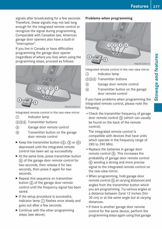
signals after broadcasting for a few seconds.Therefore, these signals may not last longenough for the integrated remote control torecognize the signal during programming.Comparable with Canadian law, Americangarage door openers also have a built-in"interruption".If you live in Canada or have difficultiesprogramming the garage door opener(regardless of where you live) when using theprogramming steps, proceed as follows:
Integrated remote control in the rear-view mirror: Indicator lamp;=? Transmitter buttonsA Garage door remote controlB Transmitter button on the garage
door remote controlX Keep the transmitter button (;,= or?)depressed until the integrated remotecontrol has been set up successfully.
X At the same time, press transmitter buttonB of the garage door remote control fortwo seconds, then release it for twoseconds, then press it again for twoseconds.
X Repeat this sequence on transmitterbuttonB of the garage door remotecontrol until the frequency signal has beensaved.
X If the setup procedure is successful,indicator lamp: flashes once slowly andgoes out after a few seconds.
X Continue with the other programmingsteps (see above).
Problems when programming
Integrated remote control in the rear-view mirror: Indicator lamp;=? Transmitter buttonsA Garage door remote controlB Transmitter button on the garage
door remote controlIf you have problems when programming theintegrated remote control, please note thefollowing:RCheck the transmitter frequency of garagedoor remote controlA (which can usuallybe found on the back of the remotecontrol).The integrated remote control iscompatible with devices that have unitswhich operate in the frequency range of280 to 390 MHz.RReplace the batteries in garage doorremote controlA. This increases theprobability of garage door remote controlA sending a strong and more precisesignal to the integrated remote control onthe rear-view mirror.RWhen programming, hold garage doorremote controlA at varying distances andangles from the transmitter button whichyou are programming. Try various angles ata distance between 2and 12 inches (5to30 cm) or at the same angle but at varyingdistances.RIf there is another garage door remotecontrol for the same device, perform theprogramming steps again using that garage
Features 277
Stow
ageandfeatures
Z
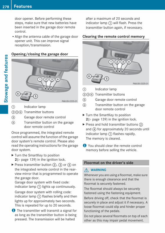
door opener. Before performing thesesteps, make sure that new batteries havebeen inserted in the garage door remotecontrol.RAlign the antenna cable of the garage dooropener unit. This can improve signalreception/transmission.
Opening/closing the garage door
: Indicator lamp;=? Transmitter buttonsA Garage door remote controlB Transmitter button on the garage
door remote controlOnce programmed, the integrated remotecontrol will assume the function of the garagedoor system's remote control. Please alsoread the operating instructions for the garagedoor system.X Turn the SmartKey to position2(Y page 139) in the ignition lock.
X Press transmitter button;,= or? onthe integrated remote control in the rear-view mirror that is programmed to operatethe garage door.Garage door system with fixed code:indicator lamp: lights up continuously.Garage door system with rolling code:indicator lamp: flashes briefly and thenlights up for approximately two seconds.This is repeated for up to 20 seconds.i The transmitter will transmit a signal foras long as the transmitter button is beingpressed. The transmission will be halted
after a maximum of 20 seconds andindicator lamp: will flash. Press thetransmitter button again, if necessary.
Clearing the remote control memory
: Indicator lamp;=? Transmitter buttonsA Garage door remote controlB Transmitter button on the garage
door remote controlX Turn the SmartKey to position2(Y page 139) in the ignition lock.
X Press and hold transmitter buttons;and? for approximately 20 seconds untilindicator lamp: flashes rapidly.The memory is cleared.
i You should clear the remote controlmemory before selling the vehicle.
Floormat on the driver's side
G WARNINGWhenever you are using a floormat,make surethere is enough clearance and that thefloormat is securely fastened.The floormat should always be securelyfastened using the fastening equipment.Before driving off, check that the floormat issecurely in place and adjust it if necessary. Aloose floormat could slip and hinder properfunctioning of the pedals.Do not place several floormats on top of eachother as this may impair pedal movement.
278 FeaturesStow
ageandfeatures
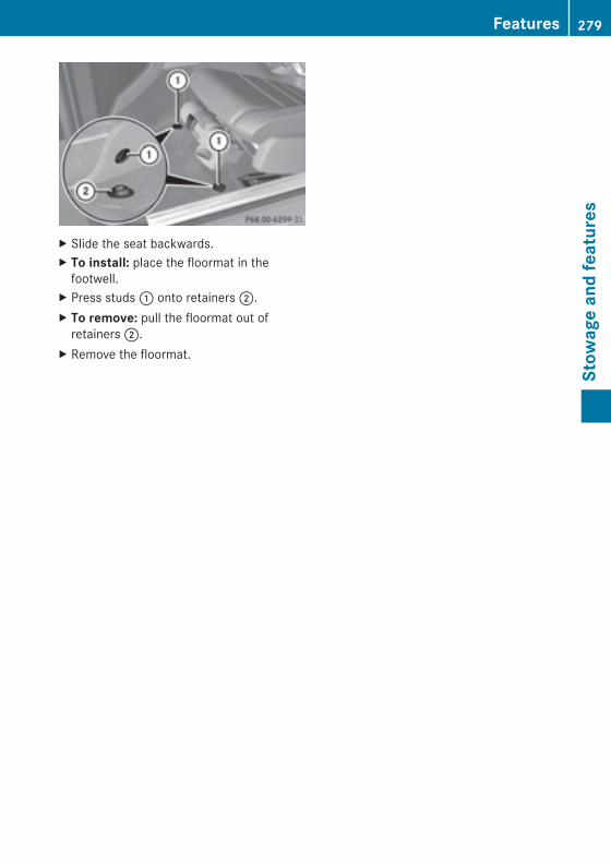
X Slide the seat backwards.X To install: place the floormat in thefootwell.
X Press studs: onto retainers;.X To remove: pull the floormat out ofretainers;.
X Remove the floormat.
Features 279
Stow
ageandfeatures
Z

280

Useful information ............................ 282Engine compartment ........................ 282Maintenance ...................................... 286Care .................................................... 288
281
Maintenance
andcare
Useful information
i This Operator's Manual describes allmodels and all standard and optionalequipment of your vehicle available at thetime of publication of the Operator'sManual. Country-specific differences arepossible. Please note that your vehicle maynot be equipped with all featuresdescribed. This also applies to safety-related systems and functions.
i Read the information on qualifiedspecialist workshops: (Y page 24).
Engine compartment
Hood
Important safety notes
G WARNINGIf the hood is unlatched, it may open up whenthe vehicle is in motion and block your view.There is a risk of an accident.Never unlatch the hood while driving.
G WARNINGCertain components in the enginecompartment may be very hot, e.g. the drivesystem and radiator. Working in the enginecompartment poses a risk of injury.If possible, let the drive system cool down andonly touch the following describedcomponents.
G WARNINGOpening the hood when the engine isoverheated or when there is a fire in theengine compartment could expose you to hotgases or other service products. There is arisk of injury.Let an overheated engine cool down beforeopening the hood. If there is a fire in theengine compartment, keep the hood closedand contact the fire department.
G WARNINGThe engine compartment contains movingcomponents. Certain components, such asthe radiator fan, may continue to run or startagain suddenly when the ignition is off. Thereis a risk of injury.If you need to do any work inside the enginecompartment:Rswitch off the ignitionRnever reach into the area where there is arisk of danger from moving components,such as the fan rotation areaRremove jewelery and watchesRkeep items of clothing and hair, forexample, away from moving parts
G WARNINGThe engine is equipped with a transistorizedignition system. Because of the high voltage,it is dangerous to touch any components(ignition coils, spark plug sockets, diagnosticsocket) of the ignition system:Rwith the engine runningRwhile starting the engineRwhen the ignition is switched on and theengine is turned manually
G WARNINGWhen the hood is open and the windshieldwipers are set in motion, you can be injuredby the wiper linkage. There is a risk of injury.Always switch off the windshield wipers andthe ignition before opening the hood.
! Make sure that the windshield wipers arenot folded away from the windshield. Youcould otherwise damage the windshieldwipers or the hood.
Do not touch the following when the ignitionis switched on:Rignition coilsRspark plug connectorsRtest socket
282 Engine compartmentMaintenance
andcare
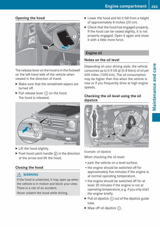
Opening the hood
The release lever on the hood is in the footwellon the left-hand side of the vehicle whenviewed in the direction of travel.X Make sure that the windshield wipers areturned off.
X Pull release lever: on the hood.The hood is released.
X Lift the hood slightly.X Push hood catch handle; in the directionof the arrow and lift the hood.
Closing the hood
G WARNINGIf the hood is unlatched, it may open up whenthe vehicle is in motion and block your view.There is a risk of an accident.Never unlatch the hood while driving.
X Lower the hood and let it fall from a heightof approximately 8 inches (20 cm).
X Check that the hood has engaged properly.If the hood can be raised slightly, it is notproperly engaged. Open it again and closeit with a little more force.
Engine oil
Notes on the oil levelDepending on your driving style, the vehicleconsumes up to 0.9 US qt (0.8 liters) of oil per600 miles (1000 km). The oil consumptionmay be higher than this when the vehicle isnew or if you frequently drive at high enginespeeds.
Checking the oil level using the oildipstick
Example: oil dipstick
When checking the oil level:Rpark the vehicle on a level surface.Rthe engine should be switched off forapproximately five minutes if the engine isat normal operating temperature.Rthe engine should be switched off for atleast 30 minutes if the engine is not atoperating temperature, e.g. if you only startthe engine briefly.
X Pull oil dipstick: out of the dipstick guidetube.
X Wipe off oil dipstick:.
Engine compartment 283
Maintenance
andcare
Z
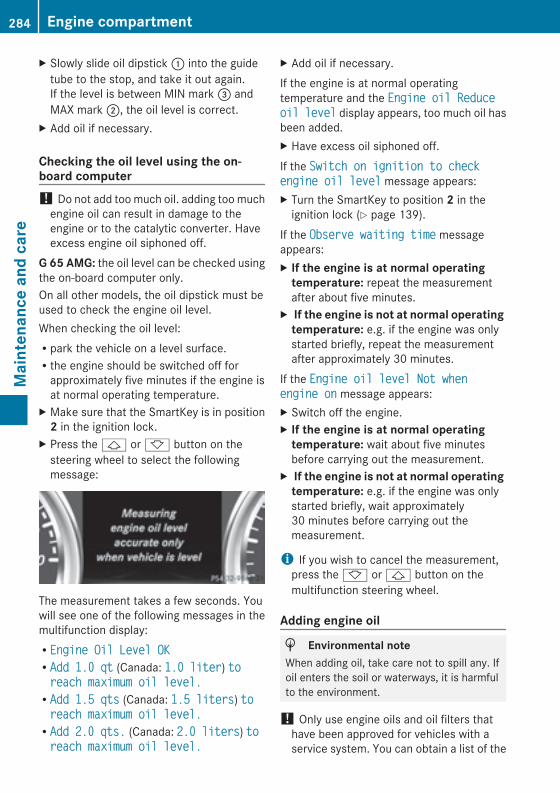
X Slowly slide oil dipstick: into the guidetube to the stop, and take it out again.If the level is between MIN mark= andMAX mark;, the oil level is correct.
X Add oil if necessary.
Checking the oil level using the on-board computer! Do not add toomuch oil. adding toomuchengine oil can result in damage to theengine or to the catalytic converter. Haveexcess engine oil siphoned off.
G 65 AMG: the oil level can be checked usingthe on-board computer only.On all other models, the oil dipstick must beused to check the engine oil level.When checking the oil level:Rpark the vehicle on a level surface.Rthe engine should be switched off forapproximately five minutes if the engine isat normal operating temperature.
X Make sure that the SmartKey is in position2 in the ignition lock.
X Press the& or* button on thesteering wheel to select the followingmessage:
The measurement takes a few seconds. Youwill see one of the following messages in themultifunction display:REngine Oil Level OKEngine Oil Level OKRAdd 1.0 qtAdd 1.0 qt (Canada: 1.0 liter1.0 liter) totoreach maximum oil level.reach maximum oil level.RAdd 1.5 qtsAdd 1.5 qts (Canada: 1.5 liters1.5 liters) totoreach maximum oil level.reach maximum oil level.RAddAdd 2.0 qts.2.0 qts. (Canada: 2.0 liters2.0 liters) totoreach maximum oil level.reach maximum oil level.
X Add oil if necessary.If the engine is at normal operatingtemperature and the Engine oil ReduceEngine oil Reduceoiloil levellevel display appears, too much oil hasbeen added.X Have excess oil siphoned off.If the Switch on ignition to checkSwitch on ignition to checkengine oil levelengine oil level message appears:X Turn the SmartKey to position 2 in theignition lock (Y page 139).
If the Observe waiting timeObserve waiting time messageappears:X If the engine is at normal operatingtemperature: repeat the measurementafter about five minutes.
X If the engine is not at normal operatingtemperature: e.g. if the engine was onlystarted briefly, repeat the measurementafter approximately 30 minutes.
If the Engine oil level Not whenEngine oil level Not whenengine onengine on message appears:X Switch off the engine.X If the engine is at normal operatingtemperature: wait about five minutesbefore carrying out the measurement.
X If the engine is not at normal operatingtemperature: e.g. if the engine was onlystarted briefly, wait approximately30 minutes before carrying out themeasurement.
i If you wish to cancel the measurement,press the* or& button on themultifunction steering wheel.
Adding engine oil
H Environmental noteWhen adding oil, take care not to spill any. Ifoil enters the soil or waterways, it is harmfulto the environment.
! Only use engine oils and oil filters thathave been approved for vehicles with aservice system. You can obtain a list of the
284 Engine compartmentMaintenance
andcare
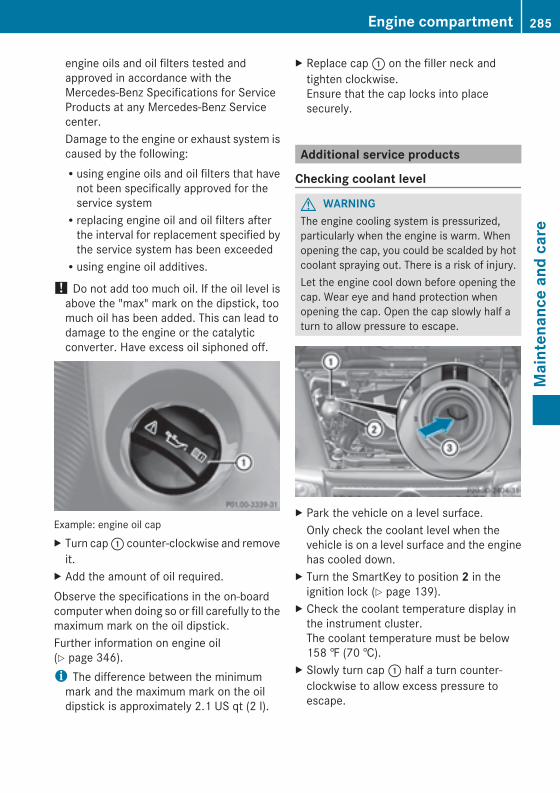
engine oils and oil filters tested andapproved in accordance with theMercedes-Benz Specifications for ServiceProducts at any Mercedes-Benz Servicecenter.Damage to the engine or exhaust system iscaused by the following:Rusing engine oils and oil filters that havenot been specifically approved for theservice systemRreplacing engine oil and oil filters afterthe interval for replacement specified bythe service system has been exceededRusing engine oil additives.
! Do not add too much oil. If the oil level isabove the "max" mark on the dipstick, toomuch oil has been added. This can lead todamage to the engine or the catalyticconverter. Have excess oil siphoned off.
Example: engine oil capX Turn cap: counter-clockwise and removeit.
X Add the amount of oil required.Observe the specifications in the on-boardcomputer when doing so or fill carefully to themaximum mark on the oil dipstick.Further information on engine oil(Y page 346).i The difference between the minimummark and the maximum mark on the oildipstick is approximately 2.1 US qt (2 l).
X Replace cap: on the filler neck andtighten clockwise.Ensure that the cap locks into placesecurely.
Additional service products
Checking coolant level
G WARNINGThe engine cooling system is pressurized,particularly when the engine is warm. Whenopening the cap, you could be scalded by hotcoolant spraying out. There is a risk of injury.Let the engine cool down before opening thecap. Wear eye and hand protection whenopening the cap. Open the cap slowly half aturn to allow pressure to escape.
X Park the vehicle on a level surface.Only check the coolant level when thevehicle is on a level surface and the enginehas cooled down.
X Turn the SmartKey to position 2 in theignition lock (Y page 139).
X Check the coolant temperature display inthe instrument cluster.The coolant temperature must be below158 ‡ (70 †).
X Slowly turn cap: half a turn counter-clockwise to allow excess pressure toescape.
Engine compartment 285
Maintenance
andcare
Z
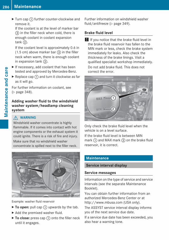
X Turn cap: further counter-clockwise andremove it.If the coolant is at the level of marker bar= in the filler neck when cold, there isenough coolant in coolant expansiontank;.If the coolant level is approximately 0.6 in(1.5 cm) above marker bar= in the fillerneck when warm, there is enough coolantin expansion tank;.
X If necessary, add coolant that has beentested and approved by Mercedes-Benz.
X Replace cap: and turn it clockwise as faras it will go.
For further information on coolant, see(Y page 348).
Adding washer fluid to the windshieldwasher system/headlamp cleaningsystem
G WARNINGWindshield washer concentrate is highlyflammable. If it comes into contact with hotengine components or the exhaust system itcould ignite. There is a risk of fire and injury.Make sure that no windshield washerconcentrate is spilled next to the filler neck.
Example: washer fluid reservoirX To open: pull cap: upwards by the tab.X Add the premixed washer fluid.X To close: press cap: onto the filler neckuntil it engages.
Further information on windshield washerfluid/antifreeze (Y page 349).
Brake fluid level! If you notice that the brake fluid level inthe brake fluid reservoir has fallen to theMIN mark or less, check the brake systemimmediately for leaks. Also check thethickness of the brake linings. Visit aqualified specialist workshop immediately.Do not add brake fluid. This does notcorrect the error.
Only check the brake fluid level when thevehicle is on a level surface.If the brake fluid level is between MINmark: and MAX mark; on the brake fluidreservoir, it is correct.
Maintenance
Service interval display
Service messagesInformation on the type of service and serviceintervals (see the separate MaintenanceBooklet).You can obtain further information from anauthorized Mercedes-Benz Center or athttp://www.mbusa.com (USA only).The ASSYST service interval display informsyou of the next service due date.If a service due date has been exceeded, youalso hear a warning tone.
286 MaintenanceMaintenance
andcare
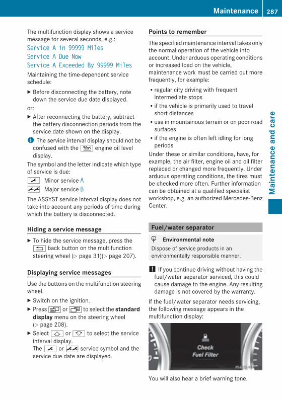
The multifunction display shows a servicemessage for several seconds, e.g.:Service A in 99999 MilesService A in 99999 MilesService A Due NowService A Due NowService A Exceeded By 99999 MilesService A Exceeded By 99999 MilesMaintaining the time-dependent serviceschedule:X Before disconnecting the battery, notedown the service due date displayed.
or:X After reconnecting the battery, subtractthe battery disconnection periods from theservice date shown on the display.i The service interval display should not beconfused with the4 engine oil leveldisplay.
The symbol and the letter indicate which typeof service is due:¯ Minor service AA± Major service BBThe ASSYST service interval display does nottake into account any periods of time duringwhich the battery is disconnected.
Hiding a service messageX To hide the service message, press the% back button on the multifunctionsteering wheel (Y page 31)(Y page 207).
Displaying service messagesUse the buttons on themultifunction steeringwheel.X Switch on the ignition.X PressV orU to select the standarddisplay menu on the steering wheel(Y page 208).
X Select& or* to select the serviceinterval display.The¯ or± service symbol and theservice due date are displayed.
Points to rememberThe specifiedmaintenance interval takes onlythe normal operation of the vehicle intoaccount. Under arduous operating conditionsor increased load on the vehicle,maintenance work must be carried out morefrequently, for example:Rregular city driving with frequentintermediate stopsRif the vehicle is primarily used to travelshort distancesRuse in mountainous terrain or on poor roadsurfacesRif the engine is often left idling for longperiods
Under these or similar conditions, have, forexample, the air filter, engine oil and oil filterreplaced or changed more frequently. Underarduous operating conditions, the tires mustbe checked more often. Further informationcan be obtained at a qualified specialistworkshop, e.g. an authorized Mercedes-BenzCenter.
Fuel/water separator
H Environmental noteDispose of service products in anenvironmentally responsible manner.
! If you continue driving without having thefuel/water separator serviced, this couldcause damage to the engine. Any resultingdamage is not covered by the warranty.
If the fuel/water separator needs servicing,the following message appears in themultifunction display:
You will also hear a brief warning tone.
Maintenance 287
Maintenance
andcare
Z
X Visit a qualified specialist workshop assoon as possible.
Care
General notes
G WARNINGMany cleaning products can be hazardous.Some are poisonous, others are flammable.Always follow the instructions on theparticular container. Always open yourvehicle's doors or windows when cleaning theinside.Never use fluids or solvents that are notdesigned for cleaning your vehicle.Always lock away cleaning products and keepthem out of reach of children.
! For cleaning your vehicle, do not use anyof the following:Rdry, rough or hard clothsRabrasive cleaning agentsRsolventsRcleaning agents containing solventsDo not scrub.Do not touch the surfaces or protectivefilms with hard objects, e.g. a ring or icescraper. You could otherwise scratch ordamage the surfaces and protective film.
! Do not park the vehicle for an extendedperiod straight after cleaning it, particularlyafter having cleaned the wheels with wheelcleaner. Wheel cleaners could causeincreased corrosion of the brake discs andbrake pads/linings. For this reason, youshould drive for a few minutes aftercleaning. Braking heats the brake discs andthe brake pads/linings, thus drying them.The vehicle can then be parked.
H Environmental noteDispose of empty packaging and cleaningcloths in an environmentally responsiblemanner.
Regular care of your vehicle is a condition forretaining the quality in the long term.Use care products and cleaning agentsrecommended and approved by Mercedes-Benz.
Exterior care
Automatic car wash
G WARNINGBraking efficiency is reduced after washingthe vehicle. There is a risk of an accident.After the vehicle has been washed, brakecarefully while paying attention to the trafficconditions until full braking power is restored.
! Never clean your vehicle in a TouchlessAutomatic Car Wash as these use specialcleaning agents. These cleaning agents candamage the paintwork or plastic parts.
! Make sure that the automatic car wash issuitable for the size of the vehicle. Fold inthe exterior mirrors before the vehicle iswashed. The exterior mirrors couldotherwise be damaged.
! Make sure that the automatictransmission is in positionNwhen washingyour vehicle in a tow-through car wash. Thevehicle could be damaged if thetransmission is in another position.
! Make sure that:Rthe side windows and sliding sunroof areclosed completely.Rthe blower for the ventilation/heating isswitched off (airflow control is turned toposition 0/theà andÁ buttonsare switched off).Rthe windshield wiper switch is at position0.
The vehicle could otherwise be damaged.You can wash the vehicle in an automatic carwash from the very start.
288 CareMaintenance
andcare
If the vehicle is very dirty, pre-wash it beforecleaning it in an automatic car wash.After using an automatic car wash, wipe offwax from the windshield and the wiperblades. This will prevent smears and reducewiping noises caused by residue on thewindshield.
Washing by handIn some countries, washing by hand is onlyallowed at specially equipped washing bays.Observe the legal requirements in allcountries concerned.When using the vehicle in winter, remove alltraces of road salt deposits carefully and assoon as possible.When washing the vehicle underbody, alsoclean the inside of the wheels.X Do not use hot water and do not wash thevehicle in direct sunlight.
X Use a soft sponge to clean.X Use a mild cleaning agent, such as a carshampoo approved by Mercedes-Benz.
X Thoroughly hose down the vehicle with agentle jet of water.
X Do not point the water jet directly towardsthe air inlets.
X Use plenty of water and rinse out thesponge frequently.
X Rinse the vehicle with clean water and drythoroughly with a chamois.
X Do not let the cleaning agent dry on thepaintwork.
Power washers
G WARNINGThe water jet from a circular jet nozzle (dirtblasters) can cause invisible exterior damageto the tires or chassis components.Components damaged in this way may failunexpectedly. There is a risk of an accident.Do not use power washers with circular jetnozzles to clean the vehicle. Have damaged
tires or chassis components replacedimmediately.
! Always maintain a distance of at least11.8 in (30 cm) between the vehicle and thepower washer nozzle. Information aboutthe correct distance is available from theequipment manufacturer.Move the power washer nozzle aroundwhen cleaning your vehicle.Do not aim directly at any of the following:RtiresRdoor gaps, roof gaps, joints, etc.Relectrical componentsRbatteryRconnectorsRlightsRsealsRtrimRventilation slotsDamaged seals or electrical componentscan lead to leaks or failures.
Cleaning the wheels! Donot use acidicwheel cleaning productsto remove brake dust. This could damagewheel bolts and brake components.
! Do not park the vehicle for an extendedperiod straight after cleaning it, particularlyafter having cleaned the wheels with wheelcleaner. Wheel cleaners could causeincreased corrosion of the brake discs andbrake pads/linings. For this reason, youshould drive for a few minutes aftercleaning. Braking heats the brake discs andthe brake pads/linings, thus drying them.The vehicle can then be parked.
Cleaning the paintwork! Do not affix:RstickersRfilmsRmagnetic plates or similar items
Care 289
Maintenance
andcare
Z
to painted surfaces. You could otherwisedamage the paintwork.
Scratches, corrosive deposits, areas affectedby corrosion and damage caused byinadequate care cannot always be completelyrepaired. In such cases, visit a qualifiedspecialist workshop.X Remove dirt immediately, where possible,while avoiding rubbing too hard.
X Soak insect remains with insect removerand rinse off the treated areas afterwards.
X Soak bird droppings with water and rinseoff the treated areas afterwards.
X Remove coolant, brake fluid, tree resin,oils, fuels and greases by rubbing gentlywith a cloth soaked in petroleum ether orlighter fluid.
X Use tar remover to remove tar stains.X Use silicone remover to remove wax.If water no longer forms "beads" on the paintsurface, use the paint care productsrecommended and approved by Mercedes-Benz. This is the case approximately everythree to five months, depending on theclimate conditions and the care product used.If dirt has penetrated the paint surface or ifthe paint has become dull, the paint cleanerrecommended and approved by Mercedes-Benz should be used.Do not use these care products in the sun oron the hood while the hood is hot.X Use a suitable touch-up stick, e.g. MBTouch-Up Stick, to correct smaller areas ofpaint damage quickly and provisionally.
Matte finish care! Never polish the vehicle or the light alloywheels. Polishing causes the finish toshine.
! Never use paint cleaner, buffing orpolishing products, or gloss preserver, e.g.wax. These products are only suitable forhigh-gloss surfaces. Their use on vehicles
with matte finish leads to considerablesurface damage (shiny, spotted areas).Always have paintwork repairs carried outat a qualified specialist workshop.
! Do not use wash programs with a hot waxtreatment under any circumstances.
If your vehicle has a clear matte finish,observe the following instructions in order toavoid damage to the paintwork due toincorrect care.These notes also apply to light alloy wheelswith a clear matte finish.
i The vehicle should preferably be washedby hand using a soft sponge, car shampooand plenty of water.
i Use only insect remover and car shampoofrom the range of recommended andapproved Mercedes-Benz care products.
Cleaning the windows
G WARNINGYou could become trapped by the windshieldwipers if they start moving while cleaning thewindshield or wiper blades. There is a risk ofinjury.Always switch off the windshield wipers andthe ignition before cleaning the windshield orwiper blades.
! Do not use dry cloths, abrasive products,solvents or cleaning agents containingsolvents to clean the inside of the windows.Do not touch the insides of the windowswith hard objects, e.g. an ice scraper orring. There is otherwise a risk of damagingthe windows.
! Clean the water drainage channels of thewindshield and the rear window at regularintervals. Deposits such as leaves, petalsand pollen may under certaincircumstances prevent water from drainingaway. This can lead to corrosion damageand damage to electronic components.
290 CareMaintenance
andcare
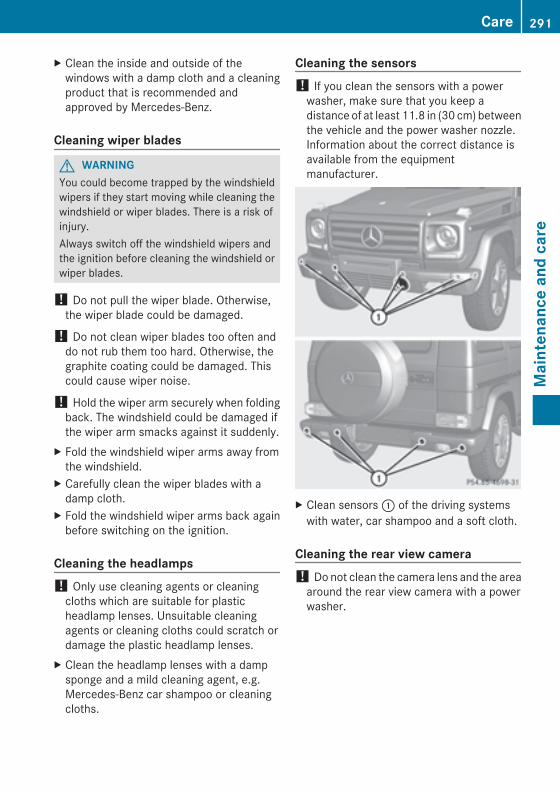
X Clean the inside and outside of thewindows with a damp cloth and a cleaningproduct that is recommended andapproved by Mercedes-Benz.
Cleaning wiper blades
G WARNINGYou could become trapped by the windshieldwipers if they start moving while cleaning thewindshield or wiper blades. There is a risk ofinjury.Always switch off the windshield wipers andthe ignition before cleaning the windshield orwiper blades.
! Do not pull the wiper blade. Otherwise,the wiper blade could be damaged.
! Do not clean wiper blades too often anddo not rub them too hard. Otherwise, thegraphite coating could be damaged. Thiscould cause wiper noise.
! Hold the wiper arm securely when foldingback. The windshield could be damaged ifthe wiper arm smacks against it suddenly.
X Fold the windshield wiper arms away fromthe windshield.
X Carefully clean the wiper blades with adamp cloth.
X Fold the windshield wiper arms back againbefore switching on the ignition.
Cleaning the headlamps! Only use cleaning agents or cleaningcloths which are suitable for plasticheadlamp lenses. Unsuitable cleaningagents or cleaning cloths could scratch ordamage the plastic headlamp lenses.
X Clean the headlamp lenses with a dampsponge and a mild cleaning agent, e.g.Mercedes-Benz car shampoo or cleaningcloths.
Cleaning the sensors! If you clean the sensors with a powerwasher, make sure that you keep adistance of at least 11.8 in (30 cm) betweenthe vehicle and the power washer nozzle.Information about the correct distance isavailable from the equipmentmanufacturer.
X Clean sensors: of the driving systemswith water, car shampoo and a soft cloth.
Cleaning the rear view camera! Do not clean the camera lens and the areaaround the rear view camera with a powerwasher.
Care 291
Maintenance
andcare
Z
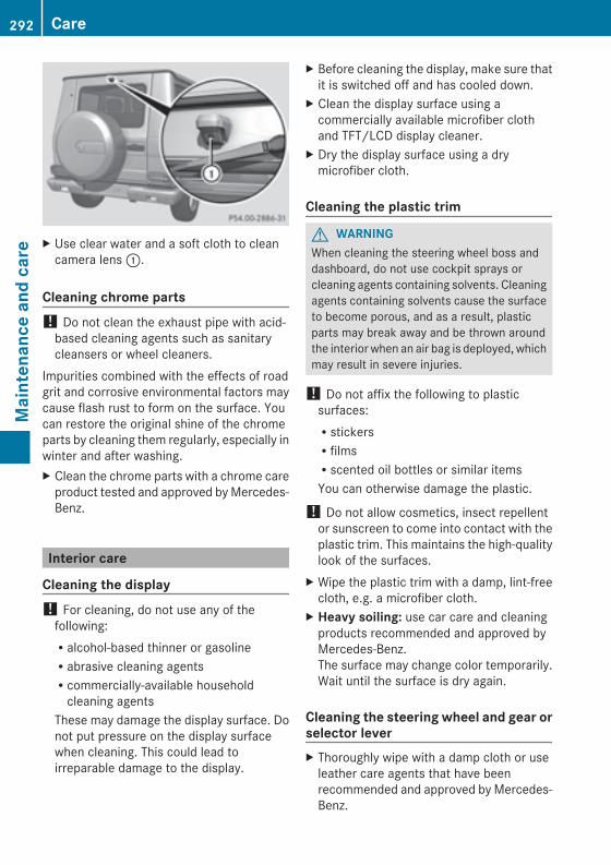
X Use clear water and a soft cloth to cleancamera lens:.
Cleaning chrome parts! Do not clean the exhaust pipe with acid-based cleaning agents such as sanitarycleansers or wheel cleaners.
Impurities combined with the effects of roadgrit and corrosive environmental factors maycause flash rust to form on the surface. Youcan restore the original shine of the chromeparts by cleaning them regularly, especially inwinter and after washing.X Clean the chrome parts with a chrome careproduct tested and approved byMercedes-Benz.
Interior care
Cleaning the display! For cleaning, do not use any of thefollowing:Ralcohol-based thinner or gasolineRabrasive cleaning agentsRcommercially-available householdcleaning agents
These may damage the display surface. Donot put pressure on the display surfacewhen cleaning. This could lead toirreparable damage to the display.
X Before cleaning the display, make sure thatit is switched off and has cooled down.
X Clean the display surface using acommercially available microfiber clothand TFT/LCD display cleaner.
X Dry the display surface using a drymicrofiber cloth.
Cleaning the plastic trim
G WARNINGWhen cleaning the steering wheel boss anddashboard, do not use cockpit sprays orcleaning agents containing solvents. Cleaningagents containing solvents cause the surfaceto become porous, and as a result, plasticparts may break away and be thrown aroundthe interior when an air bag is deployed, whichmay result in severe injuries.
! Do not affix the following to plasticsurfaces:RstickersRfilmsRscented oil bottles or similar itemsYou can otherwise damage the plastic.
! Do not allow cosmetics, insect repellentor sunscreen to come into contact with theplastic trim. This maintains the high-qualitylook of the surfaces.
X Wipe the plastic trim with a damp, lint-freecloth, e.g. a microfiber cloth.
X Heavy soiling: use car care and cleaningproducts recommended and approved byMercedes-Benz.The surface may change color temporarily.Wait until the surface is dry again.
Cleaning the steering wheel and gear orselector leverX Thoroughly wipe with a damp cloth or useleather care agents that have beenrecommended and approved by Mercedes-Benz.
292 CareMaintenance
andcare
Cleaning genuine wood and trim strips! Do not use solvent-based cleaning agentssuch as tar remover, wheel cleaners,polishes or waxes. There is otherwise a riskof damaging the surface.
! Do not use chrome polish for trim strips.The trim strips have a chrome look but aremostly made of anodized aluminum andcan lose their shine if chrome polish isused. Use a damp, lint-free cloth insteadwhen cleaning the trim strips.If the chrome-plated trim strips are verydirty, you can use a chrome polish. If youare unsure as to whether the trim strips arechrome-plated or not, consult anauthorized Mercedes-Benz Center.
X Wipe the wooden trim and trim strips witha damp, lint-free cloth, e.g. a microfibercloth.
X Heavy soiling: use car care and cleaningproducts recommended and approved byMercedes-Benz.
Cleaning the seat covers
General notes! Do not use microfiber cloths to cleangenuine leather, artificial leather orDINAMICA covers. If used often, these candamage the cover.
i Note that regular care is essential toensure that the appearance and comfort ofthe covers is retained over time.
Genuine leather seat covers! To retain the natural appearance of theleather, observe the following cleaninginstructions:RClean genuine leather covers carefullywith a damp cloth and then wipe thecovers down with a dry cloth.RMake sure that the leather does notbecome soaked. It may otherwisebecome rough and cracked.ROnly use leather care agents that havebeen tested and approved by Mercedes-Benz. You can obtain these from aqualified specialist workshop.
Leather is a natural product.It exhibits natural surface characteristics, forexample:Rdifferences in the textureRsigns of stretching and markingRslight nuances of colorThese are characteristics of leather and notmaterial defects.
Seat covers of other materials! Observe the following when cleaning:RClean artificial leather coverswith a clothmoistened with a solution containing1% detergent (e.g. dish washing liquid).RClean cloth covers with a microfibercloth moistened with a solutioncontaining 1% detergent (e.g. dishwashing liquid). Rub carefully and alwayswipe entire seat sections to avoid leavingvisible lines. Leave the seat to dryafterwards. Cleaning results depend onthe type of dirt and how long it has beenthere.RClean Alcantara® covers with a dampcloth. Make sure that you wipe entireseat sections to avoid leaving visiblelines.
Care 293
Maintenance
andcare
Z
Cleaning the seat belts
G WARNINGDo not bleach or dye seat belts as this mayseverely weaken them. In a crash, they maynot be able to provide adequate protection.
! Donot clean the seat belts using chemicalcleaning agents. Do not dry the seat beltsby heating at temperatures above 176 ‡(80 †) or in direct sunlight.
X Use clean, lukewarm water and soapsolution.
Cleaning the headliner and carpetsX Headliner: if it is very dirty, use a soft brushor dry shampoo.
X Carpets: use the carpet and textilecleaning agents recommended andapproved by Mercedes-Benz.
294 CareMaintenance
andcare
Useful information ............................ 296Where will I find...? ........................... 296Flat tire .............................................. 298Battery (vehicle) ................................ 299Jump-starting .................................... 303Towing and tow-starting .................. 305Fuses .................................................. 308
295
Breakdow
nassistance
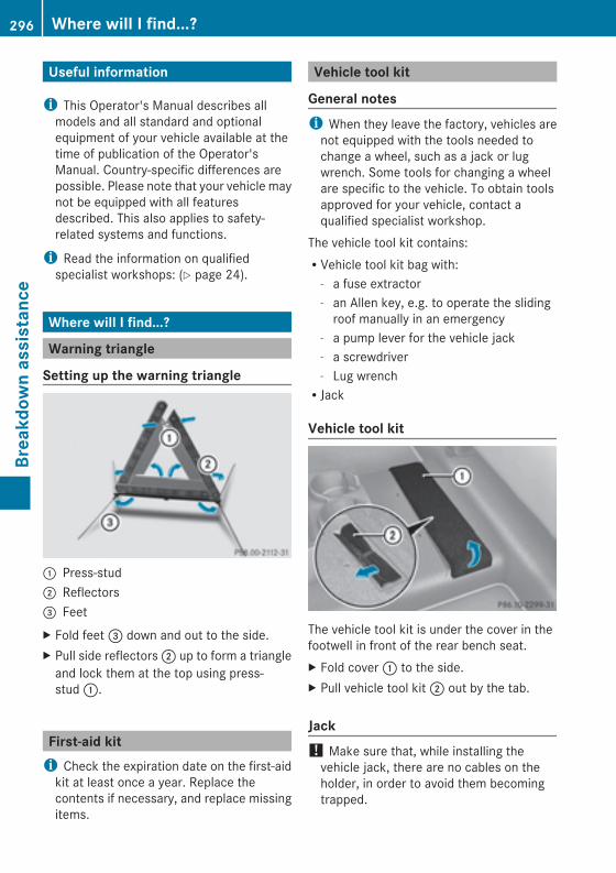
Useful information
i This Operator's Manual describes allmodels and all standard and optionalequipment of your vehicle available at thetime of publication of the Operator'sManual. Country-specific differences arepossible. Please note that your vehicle maynot be equipped with all featuresdescribed. This also applies to safety-related systems and functions.
i Read the information on qualifiedspecialist workshops: (Y page 24).
Where will I find...?
Warning triangle
Setting up the warning triangle
: Press-stud; Reflectors= FeetX Fold feet= down and out to the side.X Pull side reflectors; up to form a triangleand lock them at the top using press-stud:.
First-aid kiti Check the expiration date on the first-aidkit at least once a year. Replace thecontents if necessary, and replace missingitems.
Vehicle tool kit
General notesi When they leave the factory, vehicles arenot equipped with the tools needed tochange a wheel, such as a jack or lugwrench. Some tools for changing a wheelare specific to the vehicle. To obtain toolsapproved for your vehicle, contact aqualified specialist workshop.
The vehicle tool kit contains:RVehicle tool kit bag with:
- a fuse extractor- an Allen key, e.g. to operate the slidingroof manually in an emergency
- a pump lever for the vehicle jack- a screwdriver- Lug wrenchRJack
Vehicle tool kit
The vehicle tool kit is under the cover in thefootwell in front of the rear bench seat.X Fold cover: to the side.X Pull vehicle tool kit; out by the tab.
Jack! Make sure that, while installing thevehicle jack, there are no cables on theholder, in order to avoid them becomingtrapped.
296 Where will I find...?Breakdow
nassistance
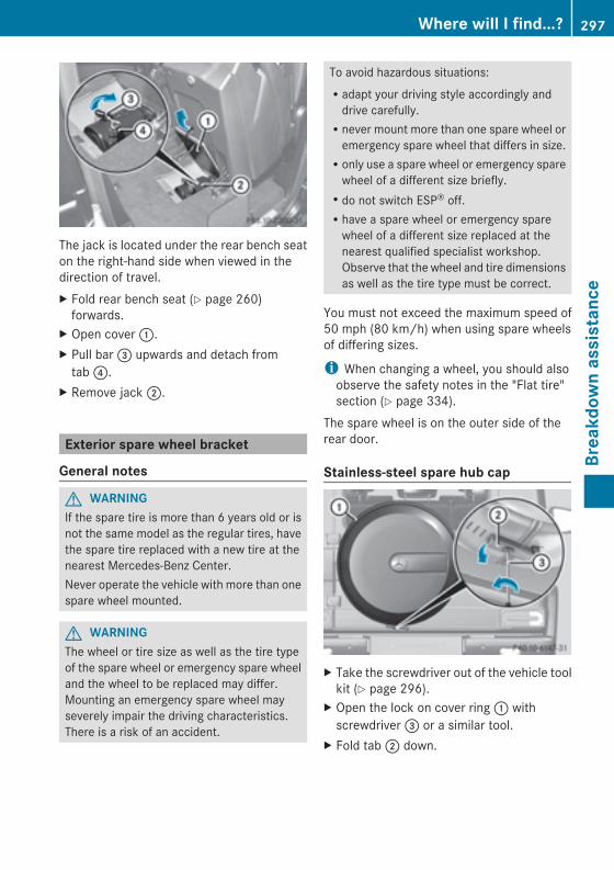
The jack is located under the rear bench seaton the right-hand side when viewed in thedirection of travel.X Fold rear bench seat (Y page 260)forwards.
X Open cover:.X Pull bar= upwards and detach fromtab?.
X Remove jack;.
Exterior spare wheel bracket
General notes
G WARNINGIf the spare tire is more than 6 years old or isnot the same model as the regular tires, havethe spare tire replaced with a new tire at thenearest Mercedes-Benz Center.Never operate the vehicle with more than onespare wheel mounted.
G WARNINGThe wheel or tire size as well as the tire typeof the spare wheel or emergency spare wheeland the wheel to be replaced may differ.Mounting an emergency spare wheel mayseverely impair the driving characteristics.There is a risk of an accident.
To avoid hazardous situations:Radapt your driving style accordingly anddrive carefully.Rnever mount more than one spare wheel oremergency spare wheel that differs in size.Ronly use a spare wheel or emergency sparewheel of a different size briefly.Rdo not switch ESP® off.Rhave a spare wheel or emergency sparewheel of a different size replaced at thenearest qualified specialist workshop.Observe that the wheel and tire dimensionsas well as the tire type must be correct.
You must not exceed the maximum speed of50 mph (80 km/h) when using spare wheelsof differing sizes.
i When changing a wheel, you should alsoobserve the safety notes in the "Flat tire"section (Y page 334).
The spare wheel is on the outer side of therear door.
Stainless-steel spare hub cap
X Take the screwdriver out of the vehicle toolkit (Y page 296).
X Open the lock on cover ring: withscrewdriver= or a similar tool.
X Fold tab; down.
Where will I find...? 297
Breakdow
nassistance
Z
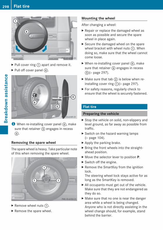
X Pull cover ring: apart and remove it.X Pull off cover panel?.
i When re-installing cover panel?, makesure that retainerA engages in recessB.
Removing the spare wheelThe sparewheel is heavy. Take particular noteof this when removing the spare wheel.
X Remove wheel nuts:.X Remove the spare wheel.
Mounting the wheelAfter changing a wheel:X Repair or replace the damaged wheel assoon as possible and secure the sparewheel in place again.
X Secure the damaged wheel on the sparewheel bracket with wheel nuts:. Whendoing so, make sure that the wheel cannotcome loose.
X When re-installing cover panel?, makesure that retainerB engages in recessA(Y page 297).
X Make sure that tab; is below when re-installing cover ring:(Y page 297).
X For safety reasons, regularly check toensure that the wheel is securely fastened.
Flat tire
Preparing the vehicleX Stop the vehicle on solid, non-slippery andlevel ground, as far away as possible fromtraffic.
X Switch on the hazard warning lamps(Y page 104).
X Apply the parking brake.X Bring the front wheels into the straight-ahead position.
X Move the selector lever to position P.X Switch off the engine.X Remove the SmartKey from the ignitionlock.The steering wheel lock stays active for aslong as the SmartKey is removed.
X All occupants must get out of the vehicle.Make sure that they are not endangered asthey do so.
X Make sure that no one is near the dangerarea while a wheel is being changed.Anyone who is not directly assisting in thewheel change should, for example, standbehind the barrier.
298 Flat tireBreakdow
nassistance
X Get out of the vehicle. Pay attention totraffic conditions when doing so.
X Close the driver's door.
Battery (vehicle)
Important safety notesSpecial tools and expert knowledge arerequired when working on the battery, e.g.removal and installing. You should thereforehave all work involving the battery carried outat a qualified specialist workshop.
G WARNINGWork carried out incorrectly on the batterycan lead, for example, to a short circuit andthus damage the vehicle electronics. This canlead to function restrictions applying tosafety-relevant systems, e.g. the lightingsystem, ABS (anti-lock braking system) orESP® (Electronic Stability Program). Theoperating safety of your vehicle may berestricted. You could lose control of thevehicle, for example:RbrakingRin the event of abrupt steering maneuverand/or when the vehicle's speed is notadapted to the road conditions
There is a risk of an accident.In the event of a short circuit or a similarincident, contact a qualified specialistworkshop immediately. Do not drive anyfurther. You should have all work involving thebattery carried out at a qualified specialistworkshop.
If ABS malfunctions, the wheels can lockduring braking. This limits the steerability ofthe vehicle when braking and may increasethe braking distance.If ESP® malfunctions, the vehicle will not bestabilized if it starts to skid or a wheel startsto spin.
G WARNINGWork carried out incorrectly on the batterycan, for example, lead to a short circuit anddamage your vehicle's electronic system. Thiscan disrupt driving safety systems such asABS (anti-lock braking system) or ESP®(Electronic Stability Program).RIf ABS malfunctions, the wheels can lockduring braking. This limits the steerabilityof the vehicle when braking and the brakingdistance may increase. There is a risk ofaccident.RIf ESP®malfunctions, the vehicle will not bestabilized if it starts to skid or a wheel startsto spin. There is a risk of accident.
You should therefore have all work involvingthe battery carried out at a qualified specialistworkshop.
G WARNINGDuring the charging process, a batteryproduces hydrogen gas. If a short circuitoccurs or sparks are created, the hydrogengas can ignite. There is a risk of an explosion.RMake sure that the positive terminal of aconnected battery does not come intocontact with vehicle parts.RNever place metal objects or tools on abattery.RIt is important that you observe thedescribed order of the battery terminalswhen connecting and disconnecting abattery.RWhen jump-starting, make sure that thebattery poles with identical polarity areconnected.RIt is particularly important to observe thedescribed order when connecting anddisconnecting the jumper cables.RNever connect or disconnect the batteryterminals while the engine is running.
G WARNINGElectrostatic build-up can lead to the creationof sparks, which could ignite the highly
Battery (vehicle) 299
Breakdow
nassistance
Z
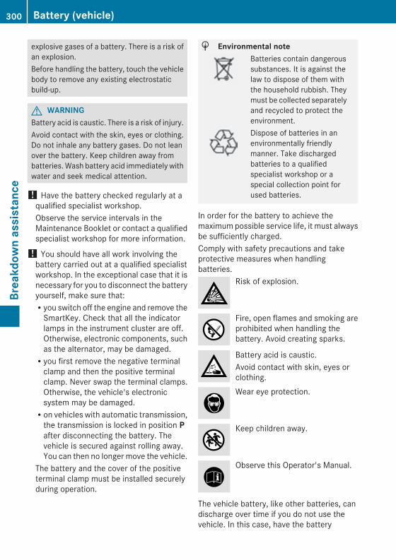
explosive gases of a battery. There is a risk ofan explosion.Before handling the battery, touch the vehiclebody to remove any existing electrostaticbuild-up.
G WARNINGBattery acid is caustic. There is a risk of injury.Avoid contact with the skin, eyes or clothing.Do not inhale any battery gases. Do not leanover the battery. Keep children away frombatteries. Wash battery acid immediately withwater and seek medical attention.
! Have the battery checked regularly at aqualified specialist workshop.Observe the service intervals in theMaintenance Booklet or contact a qualifiedspecialist workshop for more information.
! You should have all work involving thebattery carried out at a qualified specialistworkshop. In the exceptional case that it isnecessary for you to disconnect the batteryyourself, make sure that:Ryou switch off the engine and remove theSmartKey. Check that all the indicatorlamps in the instrument cluster are off.Otherwise, electronic components, suchas the alternator, may be damaged.Ryou first remove the negative terminalclamp and then the positive terminalclamp. Never swap the terminal clamps.Otherwise, the vehicle's electronicsystem may be damaged.Ron vehicles with automatic transmission,the transmission is locked in position Pafter disconnecting the battery. Thevehicle is secured against rolling away.You can then no longer move the vehicle.
The battery and the cover of the positiveterminal clamp must be installed securelyduring operation.
H Environmental noteBatteries contain dangeroussubstances. It is against thelaw to dispose of them withthe household rubbish. Theymust be collected separatelyand recycled to protect theenvironment.Dispose of batteries in anenvironmentally friendlymanner. Take dischargedbatteries to a qualifiedspecialist workshop or aspecial collection point forused batteries.
In order for the battery to achieve themaximum possible service life, it must alwaysbe sufficiently charged.Comply with safety precautions and takeprotective measures when handlingbatteries.
Risk of explosion.
Fire, open flames and smoking areprohibited when handling thebattery. Avoid creating sparks.
Battery acid is caustic.Avoid contact with skin, eyes orclothing.Wear eye protection.
Keep children away.
Observe this Operator's Manual.
The vehicle battery, like other batteries, candischarge over time if you do not use thevehicle. In this case, have the battery
300 Battery (vehicle)Breakdow
nassistance
disconnected at a qualified specialistworkshop. You can also charge the batterywith a charger recommended by Mercedes-Benz. Contact a qualified specialist workshopfor further information.Explosive gases are created during chargingand jump-starting.For safety reasons, Mercedes-Benzrecommends that you only use batterieswhich have been tested and approved foryour vehicle by Mercedes-Benz. Thesebatteries provide increased impactprotection to prevent vehicle occupants fromsuffering acid burns should the battery bedamaged in the event of an accident.Have the battery condition of charge checkedmore frequently if you use the vehicle mainlyfor short trips or if you leave it standing idlefor a lengthy period. Consult a qualifiedspecialist workshop if you wish to leave yourvehicle parked for a long period of time.
i Remove the SmartKey if you park thevehicle and do not require any electricalconsumers. The vehicle will then use verylittle energy, thus conserving batterypower.
i If the power supply has been interrupted,e.g. due to a discharged battery, you willhave to:Rset the clock. Information on setting theclock can be found in the separateoperating instructions.On vehicles with COMAND and anavigation system, the clock is setautomatically.Rreset the head restraints on the frontseats (Y page 87)Rreset the function for folding the exteriormirrors in/out automatically, by foldingthe mirrors out once (Y page 93).
Charging the battery
G WARNINGDuring charging and jump-starting, explosivegases can escape from the battery. There is arisk of an explosion.Particularly avoid fire, open flames, creatingsparks and smoking. Ensure there is sufficientventilation while charging and jump-starting.Do not lean over a battery.
G WARNINGBattery acid is caustic. There is a risk of injury.Avoid contact with the skin, eyes or clothing.Do not inhale any battery gases. Do not leanover the battery. Keep children away frombatteries. Wash battery acid immediately withwater and seek medical attention.
G WARNINGA discharged battery can freeze attemperatures below freezing point. Whenjump-starting the vehicle or charging thebattery, gases can escape from the battery.There is a risk of an explosion.Allow the frozen battery to thaw out beforecharging it or jump-starting.
! Only charge the battery using the jump-starting connection point.
! Only use battery chargers with amaximum charging voltage of 14.8 V.
! Only charge the installed battery with abattery charger which has been tested andapproved byMercedes-Benz. These batterychargers allow the battery to be chargedwhile still installed in the vehicle.
A battery charger unit specially adapted forMercedes-Benz vehicles and tested andapproved byMercedes-Benz is available as anaccessory. Contact an authorized Mercedes-Benz Center for information and availability.Charge the battery in accordance with theoperating instructions for the batterycharger.
Battery (vehicle) 301
Breakdow
nassistance
Z
The jump-starting connection point is in theengine compartment (Y page 303).X Read the operating instructions for thebattery charger.
X Open the hood (Y page 283).X Connect the battery charger to the positiveterminal and ground point in the sameorder as when connecting the donorbattery in the jump-starting procedure(Y page 303).
302 Battery (vehicle)Breakdow
nassistance
Jump-starting
G WARNINGBattery acid is caustic. There is a risk of injury.Avoid contact with the skin, eyes or clothing. Do not inhale any battery gases. Do not lean overthe battery. Keep children away from batteries. Wash battery acid immediately with water andseek medical attention.
G WARNINGDuring charging and jump-starting, explosive gases can escape from the battery. There is a riskof an explosion.Particularly avoid fire, open flames, creating sparks and smoking. Ensure there is sufficientventilation while charging and jump-starting. Do not lean over a battery.
G WARNINGDuring the charging process, a battery produces hydrogen gas. If a short circuit occurs or sparksare created, the hydrogen gas can ignite. There is a risk of an explosion.RMake sure that the positive terminal of a connected battery does not come into contact withvehicle parts.RNever place metal objects or tools on a battery.RIt is important that you observe the described order of the battery terminals when connectingand disconnecting a battery.RWhen jump-starting, make sure that the battery poles with identical polarity are connected.RIt is particularly important to observe the described order when connecting and disconnectingthe jumper cables.RNever connect or disconnect the battery terminals while the engine is running.
G WARNINGA discharged battery can freeze at temperatures below freezing point. When jump-starting thevehicle or charging the battery, gases can escape from the battery. There is a risk of an explosion.Allow the frozen battery to thaw out before charging it or jump-starting.
G WARNINGNon-combusted fuel can collect in the exhaust system and ignite. There is a risk of fire. Avoidrepeated and lengthy starting attempts.
! Avoid repeated and lengthy starting attempts. Otherwise, non-combusted fuel maydamage the catalytic converter and create a risk of fire.Do not use a rapid charging device to start the vehicle.Make sure the jumper cables are not damaged.Make sure the jumper cables are not touching any other metal objects when they areconnected to the battery.
Jump-starting 303
Breakdow
nassistance
Z
If the indicator/warning lamps do not light up at temperatures around or below freezing point,the discharged battery is likely to be frozen (a commonplace scenario). In this case, do notjump-start the vehicle or recharge the battery.Once the battery has thawed out, its service life may be dramatically reduced.The starting characteristics can be impaired, particularly at low temperatures.It is recommended that you have the thawed out battery checked at a qualified specialistworkshop.Do not start the vehicle using a rapid charging device. If your vehicle's battery is discharged,the engine can be jump-started from another vehicle or from a second battery using jumpercables. Observe the following points:RThe battery is not accessible in all vehicles. If the other vehicle's battery is not accessible,jump-start the vehicle using a second battery or a jump-starting device.RVehicles with a gasoline engine: only jump-start the vehicle when the engine and exhaustsystem are cold.RDo not start the engine if the battery is frozen. Let the battery thaw first.RJump-starting may only be performed from batteries with a nominal voltage of 12 V.ROnly use jumper cables which have a sufficient cross-section and insulated terminal clamps.RIf the battery is fully discharged, leave the battery that is being used to jump-start connectedfor a few minutes before attempting to start. This charges the empty battery a little.RMake sure that the two vehicles do not touch.Make sure that:Rthe jumper leads are not damaged.Rwhen the jumper cables are connected to the battery, uninsulated sections of the terminalclamp do not come into contact with other metal sections.RThe jumper cables cannot come into contact with parts such as the pulley or the fan. Theseparts move when the engine is started and while it is running.
X Apply the parking brake.X Move the selector lever to position P.X Switch off all electrical consumers (e.g. radio, blower, etc.).X Open the hood (Y page 283).
304 Jump-startingBreakdow
nassistance
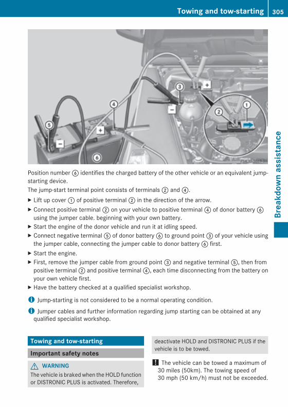
Position numberB identifies the charged battery of the other vehicle or an equivalent jump-starting device.The jump-start terminal point consists of terminals; and?.X Lift up cover: of positive terminal; in the direction of the arrow.X Connect positive terminal; on your vehicle to positive terminal? of donor batteryBusing the jumper cable. beginning with your own battery.
X Start the engine of the donor vehicle and run it at idling speed.X Connect negative terminalA of donor batteryB to ground point= of your vehicle usingthe jumper cable, connecting the jumper cable to donor batteryB first.
X Start the engine.X First, remove the jumper cable from ground point= and negative terminalA, then frompositive terminal; and positive terminal?, each time disconnecting from the battery onyour own vehicle first.
X Have the battery checked at a qualified specialist workshop.
i Jump-starting is not considered to be a normal operating condition.
i Jumper cables and further information regarding jump starting can be obtained at anyqualified specialist workshop.
Towing and tow-starting
Important safety notes
G WARNINGThe vehicle is brakedwhen the HOLD functionor DISTRONIC PLUS is activated. Therefore,
deactivate HOLD and DISTRONIC PLUS if thevehicle is to be towed.
! The vehicle can be towed a maximum of30 miles (50km). The towing speed of30 mph (50 km/h) must not be exceeded.
Towing and tow-starting 305
Breakdow
nassistance
Z
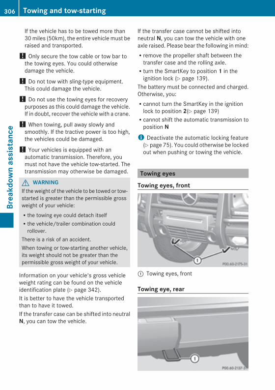
If the vehicle has to be towed more than30miles (50km), the entire vehicle must beraised and transported.
! Only secure the tow cable or tow bar tothe towing eyes. You could otherwisedamage the vehicle.
! Do not tow with sling-type equipment.This could damage the vehicle.
! Do not use the towing eyes for recoverypurposes as this could damage the vehicle.If in doubt, recover the vehicle with a crane.
! When towing, pull away slowly andsmoothly. If the tractive power is too high,the vehicles could be damaged.
! Your vehicles is equipped with anautomatic transmission. Therefore, youmust not have the vehicle tow-started. Thetransmission may otherwise be damaged.
G WARNINGIf the weight of the vehicle to be towed or tow-started is greater than the permissible grossweight of your vehicle:Rthe towing eye could detach itselfRthe vehicle/trailer combination couldrollover.
There is a risk of an accident.When towing or tow-starting another vehicle,its weight should not be greater than thepermissible gross weight of your vehicle.
Information on your vehicle's gross vehicleweight rating can be found on the vehicleidentification plate (Y page 342).It is better to have the vehicle transportedthan to have it towed.If the transfer case can be shifted into neutralN, you can tow the vehicle.
If the transfer case cannot be shifted intoneutral N, you can tow the vehicle with oneaxle raised. Please bear the following in mind:Rremove the propeller shaft between thetransfer case and the rolling axle.Rturn the SmartKey to position 1 in theignition lock (Y page 139).
The battery must be connected and charged.Otherwise, you:Rcannot turn the SmartKey in the ignitionlock to position 2(Y page 139)Rcannot shift the automatic transmission toposition Ni Deactivate the automatic locking feature(Y page 75). You could otherwise be lockedout when pushing or towing the vehicle.
Towing eyes
Towing eyes, front
: Towing eyes, front
Towing eye, rear
306 Towing and tow-startingBreakdow
nassistance
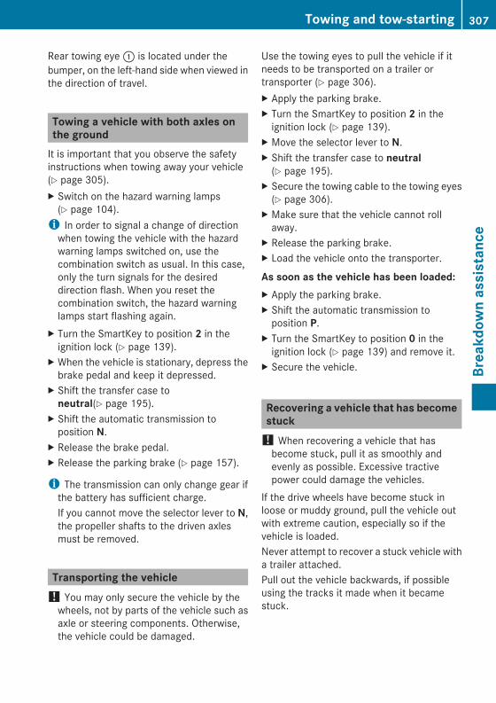
Rear towing eye: is located under thebumper, on the left-hand side when viewed inthe direction of travel.
Towing a vehicle with both axles onthe groundIt is important that you observe the safetyinstructions when towing away your vehicle(Y page 305).X Switch on the hazard warning lamps(Y page 104).i In order to signal a change of directionwhen towing the vehicle with the hazardwarning lamps switched on, use thecombination switch as usual. In this case,only the turn signals for the desireddirection flash. When you reset thecombination switch, the hazard warninglamps start flashing again.
X Turn the SmartKey to position 2 in theignition lock (Y page 139).
X When the vehicle is stationary, depress thebrake pedal and keep it depressed.
X Shift the transfer case toneutral(Y page 195).
X Shift the automatic transmission toposition N.
X Release the brake pedal.X Release the parking brake (Y page 157).
i The transmission can only change gear ifthe battery has sufficient charge.If you cannot move the selector lever to N,the propeller shafts to the driven axlesmust be removed.
Transporting the vehicle! You may only secure the vehicle by thewheels, not by parts of the vehicle such asaxle or steering components. Otherwise,the vehicle could be damaged.
Use the towing eyes to pull the vehicle if itneeds to be transported on a trailer ortransporter (Y page 306).X Apply the parking brake.X Turn the SmartKey to position 2 in theignition lock (Y page 139).
X Move the selector lever to N.X Shift the transfer case to neutral(Y page 195).
X Secure the towing cable to the towing eyes(Y page 306).
X Make sure that the vehicle cannot rollaway.
X Release the parking brake.X Load the vehicle onto the transporter.
As soon as the vehicle has been loaded:X Apply the parking brake.X Shift the automatic transmission toposition P.
X Turn the SmartKey to position 0 in theignition lock (Y page 139) and remove it.
X Secure the vehicle.
Recovering a vehicle that has becomestuck! When recovering a vehicle that hasbecome stuck, pull it as smoothly andevenly as possible. Excessive tractivepower could damage the vehicles.
If the drive wheels have become stuck inloose or muddy ground, pull the vehicle outwith extreme caution, especially so if thevehicle is loaded.Never attempt to recover a stuck vehicle witha trailer attached.Pull out the vehicle backwards, if possibleusing the tracks it made when it becamestuck.
Towing and tow-starting 307
Breakdow
nassistance
Z
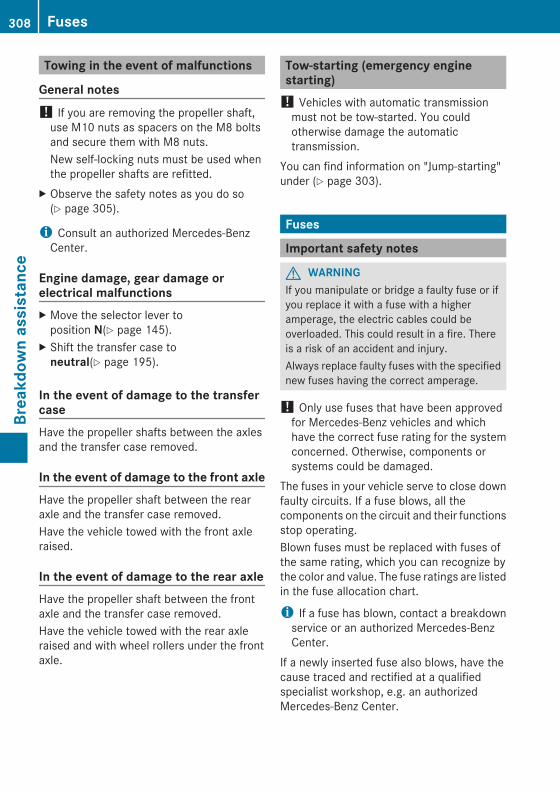
Towing in the event of malfunctions
General notes! If you are removing the propeller shaft,use M10 nuts as spacers on the M8 boltsand secure them with M8 nuts.New self-locking nuts must be used whenthe propeller shafts are refitted.
X Observe the safety notes as you do so(Y page 305).
i Consult an authorized Mercedes-BenzCenter.
Engine damage, gear damage orelectrical malfunctionsX Move the selector lever toposition N(Y page 145).
X Shift the transfer case toneutral(Y page 195).
In the event of damage to the transfercaseHave the propeller shafts between the axlesand the transfer case removed.
In the event of damage to the front axleHave the propeller shaft between the rearaxle and the transfer case removed.Have the vehicle towed with the front axleraised.
In the event of damage to the rear axleHave the propeller shaft between the frontaxle and the transfer case removed.Have the vehicle towed with the rear axleraised and with wheel rollers under the frontaxle.
Tow-starting (emergency enginestarting)! Vehicles with automatic transmissionmust not be tow-started. You couldotherwise damage the automatictransmission.
You can find information on "Jump-starting"under (Y page 303).
Fuses
Important safety notes
G WARNINGIf you manipulate or bridge a faulty fuse or ifyou replace it with a fuse with a higheramperage, the electric cables could beoverloaded. This could result in a fire. Thereis a risk of an accident and injury.Always replace faulty fuses with the specifiednew fuses having the correct amperage.
! Only use fuses that have been approvedfor Mercedes-Benz vehicles and whichhave the correct fuse rating for the systemconcerned. Otherwise, components orsystems could be damaged.
The fuses in your vehicle serve to close downfaulty circuits. If a fuse blows, all thecomponents on the circuit and their functionsstop operating.Blown fuses must be replaced with fuses ofthe same rating, which you can recognize bythe color and value. The fuse ratings are listedin the fuse allocation chart.
i If a fuse has blown, contact a breakdownservice or an authorized Mercedes-BenzCenter.
If a newly inserted fuse also blows, have thecause traced and rectified at a qualifiedspecialist workshop, e.g. an authorizedMercedes-Benz Center.
308 FusesBreakdow
nassistance
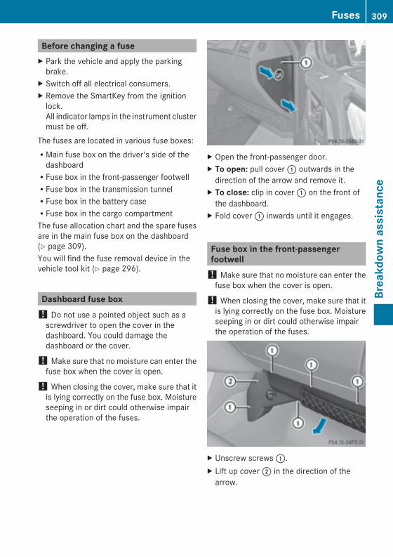
Before changing a fuseX Park the vehicle and apply the parkingbrake.
X Switch off all electrical consumers.X Remove the SmartKey from the ignitionlock.All indicator lamps in the instrument clustermust be off.
The fuses are located in various fuse boxes:RMain fuse box on the driver's side of thedashboardRFuse box in the front-passenger footwellRFuse box in the transmission tunnelRFuse box in the battery caseRFuse box in the cargo compartmentThe fuse allocation chart and the spare fusesare in the main fuse box on the dashboard(Y page 309).You will find the fuse removal device in thevehicle tool kit (Y page 296).
Dashboard fuse box! Do not use a pointed object such as ascrewdriver to open the cover in thedashboard. You could damage thedashboard or the cover.
! Make sure that no moisture can enter thefuse box when the cover is open.
! When closing the cover, make sure that itis lying correctly on the fuse box. Moistureseeping in or dirt could otherwise impairthe operation of the fuses.
X Open the front-passenger door.X To open: pull cover: outwards in thedirection of the arrow and remove it.
X To close: clip in cover: on the front ofthe dashboard.
X Fold cover: inwards until it engages.
Fuse box in the front-passengerfootwell! Make sure that no moisture can enter thefuse box when the cover is open.
! When closing the cover, make sure that itis lying correctly on the fuse box. Moistureseeping in or dirt could otherwise impairthe operation of the fuses.
X Unscrew screws:.X Lift up cover; in the direction of thearrow.
Fuses 309
Breakdow
nassistance
Z
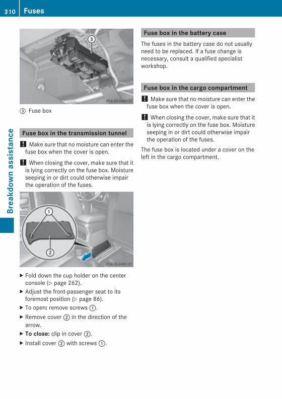
= Fuse box
Fuse box in the transmission tunnel! Make sure that no moisture can enter thefuse box when the cover is open.
! When closing the cover, make sure that itis lying correctly on the fuse box. Moistureseeping in or dirt could otherwise impairthe operation of the fuses.
X Fold down the cup holder on the centerconsole (Y page 262).
X Adjust the front-passenger seat to itsforemost position (Y page 86).
X To open: remove screws:.X Remove cover; in the direction of thearrow.
X To close: clip in cover;.X Install cover; with screws:.
Fuse box in the battery caseThe fuses in the battery case do not usuallyneed to be replaced. If a fuse change isnecessary, consult a qualified specialistworkshop.
Fuse box in the cargo compartment! Make sure that no moisture can enter thefuse box when the cover is open.
! When closing the cover, make sure that itis lying correctly on the fuse box. Moistureseeping in or dirt could otherwise impairthe operation of the fuses.
The fuse box is located under a cover on theleft in the cargo compartment.
310 FusesBreakdow
nassistance

Useful information ............................ 312Important safety notes .................... 312Operation ........................................... 313Winter operation ............................... 314Tire pressure ..................................... 316Loading the vehicle .......................... 322Uniform Tire Quality GradingStandards .......................................... 326Tire labeling ....................................... 328Changing a wheel ............................. 334Wheel and tire combinations ........... 338
311
Wheelsandtires
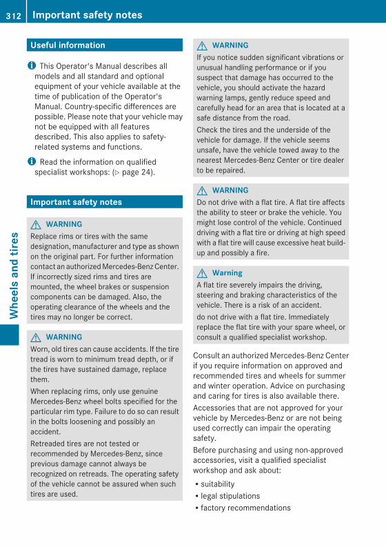
Useful information
i This Operator's Manual describes allmodels and all standard and optionalequipment of your vehicle available at thetime of publication of the Operator'sManual. Country-specific differences arepossible. Please note that your vehicle maynot be equipped with all featuresdescribed. This also applies to safety-related systems and functions.
i Read the information on qualifiedspecialist workshops: (Y page 24).
Important safety notes
G WARNINGReplace rims or tires with the samedesignation, manufacturer and type as shownon the original part. For further informationcontact an authorizedMercedes-BenzCenter.If incorrectly sized rims and tires aremounted, the wheel brakes or suspensioncomponents can be damaged. Also, theoperating clearance of the wheels and thetires may no longer be correct.
G WARNINGWorn, old tires can cause accidents. If the tiretread is worn to minimum tread depth, or ifthe tires have sustained damage, replacethem.When replacing rims, only use genuineMercedes-Benz wheel bolts specified for theparticular rim type. Failure to do so can resultin the bolts loosening and possibly anaccident.Retreaded tires are not tested orrecommended by Mercedes-Benz, sinceprevious damage cannot always berecognized on retreads. The operating safetyof the vehicle cannot be assured when suchtires are used.
G WARNINGIf you notice sudden significant vibrations orunusual handling performance or if yoususpect that damage has occurred to thevehicle, you should activate the hazardwarning lamps, gently reduce speed andcarefully head for an area that is located at asafe distance from the road.Check the tires and the underside of thevehicle for damage. If the vehicle seemsunsafe, have the vehicle towed away to thenearest Mercedes-Benz Center or tire dealerto be repaired.
G WARNINGDo not drive with a flat tire. A flat tire affectsthe ability to steer or brake the vehicle. Youmight lose control of the vehicle. Continueddriving with a flat tire or driving at high speedwith a flat tire will cause excessive heat build-up and possibly a fire.
G WarningA flat tire severely impairs the driving,steering and braking characteristics of thevehicle. There is a risk of an accident.do not drive with a flat tire. Immediatelyreplace the flat tire with your spare wheel, orconsult a qualified specialist workshop.
Consult an authorizedMercedes-Benz Centerif you require information on approved andrecommended tires and wheels for summerand winter operation. Advice on purchasingand caring for tires is also available there.Accessories that are not approved for yourvehicle by Mercedes-Benz or are not beingused correctly can impair the operatingsafety.Before purchasing and using non-approvedaccessories, visit a qualified specialistworkshop and ask about:RsuitabilityRlegal stipulationsRfactory recommendations
312 Important safety notesWheelsandtires
Information on the dimensions and types ofwheels and tires for your vehicle can be foundin the "Wheel/tire combinations" section(Y page 338).Information on air pressure for the tires onyour vehicle can be found:Ron the tire pressure label on the fuel fillerflapRin the "Tire pressure" section
i Further information on wheels and tirescan be obtained at any qualified specialistworkshop.
Operation
Notes on drivingIf the vehicle is heavily loaded, check the tirepressures and correct them if necessary.When parking your vehicle, make sure thatthe tires do not get deformed by the curb orother obstacles. If it is necessary to drive overcurbs, speed humps or similar elevations, tryto do so slowly and at an obtuse angle.Otherwise, the tires, particularly thesidewalls, may be damaged.
Regular checking of wheels and tires
G WARNINGRegularly check the tires for damage.Damaged tires can cause tire inflationpressure loss. As a result, you could losecontrol of your vehicle.Worn, old tires can cause accidents. If the tiretread is worn to minimum tread depth, or ifthe tires have sustained damage, replacethem.
RRegularly check the wheels and tires ofyour vehicle for damage at least once amonth, as well as after driving off-road oron rough roads. Damage includes bulgesand deformation on tires, cuts, punctures,cracks or severe corrosion on wheels, for
example. Damaged wheels can cause aloss of tire pressure.RRegularly check the tire tread depth andthe condition of the tread across the wholewidth of the tire (Y page 313). In order toinspect the inner side of the tire surface,turn the steering wheel to full lock.RAll wheels must have a valve cap to protectthe valve against dirt and moisture. Do notinstall anything onto the valve other thanthe standard valve cap or a valve capapproved by Mercedes-Benz for yourvehicle.Do not install anything onto the valve, suchas tire pressure monitoring systems.RYou should regularly check the pressure ofall your tires including the spare wheel,particularly prior to long trips. Adjust thetire pressure as necessary (Y page 321).
The service life of tires depends, among otherthings, on the following factors:Rdriving styleRtire pressureRdistance covered
Tire tread
G WARNINGAlthough the applicable federal motor vehiclesafety laws consider a tire to be worn whenthe treadwear indicators (TWI) become visibleat approximatelyá inches (1.6 mm), werecommend that you do not allow your tiresto wear down to that level. As tread depthapproachesâ inches (3 mm) the adhesionproperties on a wet road are sharply reduced.Depending upon the weather and/or roadsurface (conditions), the tire traction varieswidely.
Operation 313
Wheelsandtires
Z
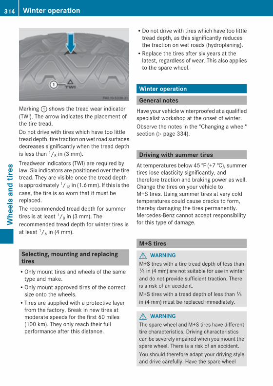
Marking: shows the tread wear indicator(TWI). The arrow indicates the placement ofthe tire tread.Do not drive with tires which have too littletread depth. tire traction onwet road surfacesdecreases significantly when the tread depthis less than 1/8 in (3 mm).Treadwear indicators (TWI) are required bylaw. Six indicators are positioned over the tiretread. They are visible once the tread depthis approximately 1/16 in (1.6mm). If this is thecase, the tire is so worn that it must bereplaced.The recommended tread depth for summertires is at least 1/8 in (3 mm). Therecommended tread depth for winter tires isat least 1/6 in (4 mm).
Selecting, mounting and replacingtiresROnly mount tires and wheels of the sametype and make.ROnly mount approved tires of the correctsize onto the wheels.RTires are supplied with a protective layerfrom the factory. Break in new tires atmoderate speeds for the first 60 miles(100 km). They only reach their fullperformance after this distance.
RDo not drive with tires which have too littletread depth, as this significantly reducesthe traction on wet roads (hydroplaning).RReplace the tires after six years at thelatest, regardless of wear. This also appliesto the spare wheel.
Winter operation
General notesHave your vehicle winterproofed at a qualifiedspecialist workshop at the onset of winter.Observe the notes in the "Changing a wheel"section (Y page 334).
Driving with summer tiresAt temperatures below 45‡ (+7†), summertires lose elasticity significantly, andtherefore traction and braking power as well.Change the tires on your vehicle toM+S tires. Using summer tires at very coldtemperatures could cause cracks to form,thereby damaging the tires permanently.Mercedes-Benz cannot accept responsibilityfor this type of damage.
M+S tires
G WARNINGM+S tires with a tire tread depth of less thanã in (4 mm) are not suitable for use in winterand do not provide sufficient traction. Thereis a risk of an accident.M+S tires with a tread depth of less thanãin (4 mm) must be replaced immediately.
G WARNINGThe spare wheel and M+S tires have differenttire characteristics. Driving characteristicscan be severely impaired when youmount thespare wheel. There is a risk of an accident.You should therefore adapt your driving styleand drive carefully. Have the spare wheel
314 Winter operationWheelsandtires
replaced with a new wheel with an M+S tireat the nearest qualified specialist workshop.
At temperatures below 45 ‡(+7 †), use all-season tires or winter tires. Both types of tireare identified by the M+S marking.Not all tires with theM+Smarking provide thedriving characteristics of winter tires. Inaddition to theM+Smarking, winter tires alsohave thei snowflake symbol on the tirewall. Tires with this marking fulfill therequirements of the Rubber ManufacturersAssociation (RMA) and the RubberAssociation of Canada (RAC) regarding snowtraction, and were specially developed fordriving on snow. Only these tires will allowdriving safety systems such as ABS andESP® to function optimally in winter, sincethese tires have been designed specificallyfor driving on snow.UseM+S tires of the samemake and tread onall wheels to maintain safe handlingcharacteristics.Always observe the maximum permissiblespeed specified for the M+S tires you havemounted.When you have mounted the M+S tires:X Check the tire pressures (Y page 316).X Restart the tire pressure monitor(Y page 321).
i You can obtain information about wintertires that have been approved byMercedes-Benz especially for your vehicleat any Mercedes-Benz Service center.
i For further information about tires, see(Y page 340).
Snow chains! Information about the use of snow chaincompatible AMG winter tires is applicablefor AMG tires. Use of snow chains is onlypermissible with these tires.
! On some tire sizes there is not enoughspace for snow chains. To avoid damage tothe vehicle or tires, observe the "Wheel andtire combinations" section under "Tires andwheels".
! If snow chains are mounted on the frontwheels, the snow chains could grindagainst the bodywork or components of thechassis. This could result in damage to thevehicle or the tires.
For safety reasons, Mercedes-Benzrecommends that you only use snow chainsthat have been specially approved for yourvehicle by Mercedes-Benz, or are of acorresponding standard of quality.ROnly use snow chains when driving onroads completely covered by snow.Remove the snow chains as soon aspossible when you come to a road that isnot snow-covered.RLocal regulations may restrict the use ofsnow chains. Observe the appropriateregulations if you wish to mount snowchains.RDo not exceed the maximum permissiblespeed of 30 mph (50 km/h).
If you intend to mount snow chains, pleasebear the following points in mind:RSnow chains cannot be mounted on allwheel/tire combinations (Y page 338).RMount snow chains only in pairs and onlyon the rear wheels. Observe themanufacturer's mounting instructions.
i You can deactivate ESP®(Y page 62)when pulling away with snow chainsinstalled. You can thereby allow the wheelsto spin in a controlledmanner, achieving anincreased driving force (cutting action).
Winter operation 315
Wheelsandtires
Z
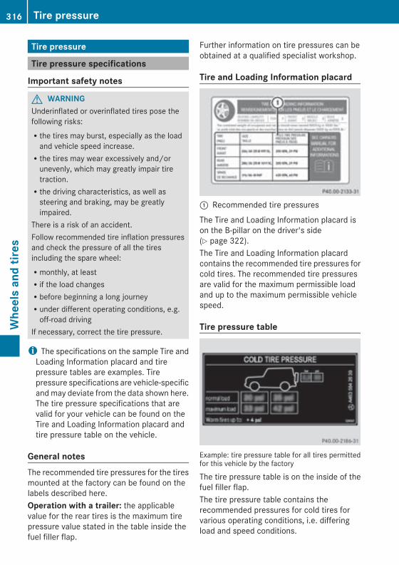
Tire pressure
Tire pressure specifications
Important safety notes
G WARNINGUnderinflated or overinflated tires pose thefollowing risks:Rthe tires may burst, especially as the loadand vehicle speed increase.Rthe tires may wear excessively and/orunevenly, which may greatly impair tiretraction.Rthe driving characteristics, as well assteering and braking, may be greatlyimpaired.
There is a risk of an accident.Follow recommended tire inflation pressuresand check the pressure of all the tiresincluding the spare wheel:Rmonthly, at leastRif the load changesRbefore beginning a long journeyRunder different operating conditions, e.g.off-road driving
If necessary, correct the tire pressure.
i The specifications on the sample Tire andLoading Information placard and tirepressure tables are examples. Tirepressure specifications are vehicle-specificand may deviate from the data shown here.The tire pressure specifications that arevalid for your vehicle can be found on theTire and Loading Information placard andtire pressure table on the vehicle.
General notesThe recommended tire pressures for the tiresmounted at the factory can be found on thelabels described here.Operation with a trailer: the applicablevalue for the rear tires is the maximum tirepressure value stated in the table inside thefuel filler flap.
Further information on tire pressures can beobtained at a qualified specialist workshop.
Tire and Loading Information placard
: Recommended tire pressures
The Tire and Loading Information placard ison the B-pillar on the driver's side(Y page 322).The Tire and Loading Information placardcontains the recommended tire pressures forcold tires. The recommended tire pressuresare valid for the maximum permissible loadand up to the maximum permissible vehiclespeed.
Tire pressure table
Example: tire pressure table for all tires permittedfor this vehicle by the factory
The tire pressure table is on the inside of thefuel filler flap.The tire pressure table contains therecommended pressures for cold tires forvarious operating conditions, i.e. differingload and speed conditions.
316 Tire pressureWheelsandtires
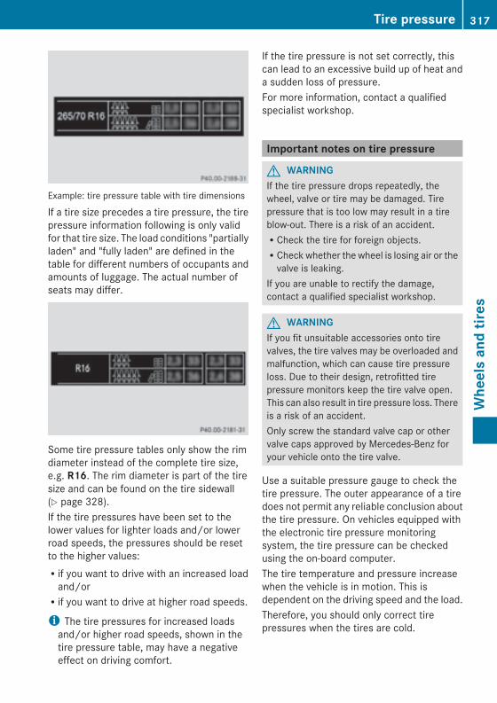
Example: tire pressure table with tire dimensions
If a tire size precedes a tire pressure, the tirepressure information following is only validfor that tire size. The load conditions "partiallyladen" and "fully laden" are defined in thetable for different numbers of occupants andamounts of luggage. The actual number ofseats may differ.
Some tire pressure tables only show the rimdiameter instead of the complete tire size,e.g. R16. The rim diameter is part of the tiresize and can be found on the tire sidewall(Y page 328).If the tire pressures have been set to thelower values for lighter loads and/or lowerroad speeds, the pressures should be resetto the higher values:Rif you want to drive with an increased loadand/orRif you want to drive at higher road speeds.
i The tire pressures for increased loadsand/or higher road speeds, shown in thetire pressure table, may have a negativeeffect on driving comfort.
If the tire pressure is not set correctly, thiscan lead to an excessive build up of heat anda sudden loss of pressure.For more information, contact a qualifiedspecialist workshop.
Important notes on tire pressure
G WARNINGIf the tire pressure drops repeatedly, thewheel, valve or tire may be damaged. Tirepressure that is too low may result in a tireblow-out. There is a risk of an accident.RCheck the tire for foreign objects.RCheck whether the wheel is losing air or thevalve is leaking.
If you are unable to rectify the damage,contact a qualified specialist workshop.
G WARNINGIf you fit unsuitable accessories onto tirevalves, the tire valves may be overloaded andmalfunction, which can cause tire pressureloss. Due to their design, retrofitted tirepressure monitors keep the tire valve open.This can also result in tire pressure loss. Thereis a risk of an accident.Only screw the standard valve cap or othervalve caps approved by Mercedes-Benz foryour vehicle onto the tire valve.
Use a suitable pressure gauge to check thetire pressure. The outer appearance of a tiredoes not permit any reliable conclusion aboutthe tire pressure. On vehicles equipped withthe electronic tire pressure monitoringsystem, the tire pressure can be checkedusing the on-board computer.The tire temperature and pressure increasewhen the vehicle is in motion. This isdependent on the driving speed and the load.Therefore, you should only correct tirepressures when the tires are cold.
Tire pressure 317
Wheelsandtires
Z
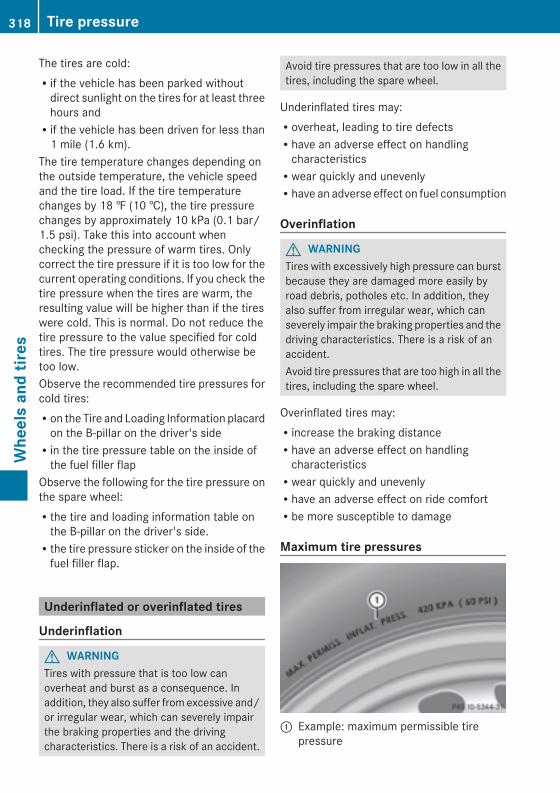
The tires are cold:Rif the vehicle has been parked withoutdirect sunlight on the tires for at least threehours andRif the vehicle has been driven for less than1 mile (1.6 km).
The tire temperature changes depending onthe outside temperature, the vehicle speedand the tire load. If the tire temperaturechanges by 18 ‡ (10 †), the tire pressurechanges by approximately 10 kPa (0.1 bar/1.5 psi). Take this into account whenchecking the pressure of warm tires. Onlycorrect the tire pressure if it is too low for thecurrent operating conditions. If you check thetire pressure when the tires are warm, theresulting value will be higher than if the tireswere cold. This is normal. Do not reduce thetire pressure to the value specified for coldtires. The tire pressure would otherwise betoo low.Observe the recommended tire pressures forcold tires:Ron the Tire and Loading Information placardon the B-pillar on the driver's sideRin the tire pressure table on the inside ofthe fuel filler flap
Observe the following for the tire pressure onthe spare wheel:Rthe tire and loading information table onthe B-pillar on the driver's side.Rthe tire pressure sticker on the inside of thefuel filler flap.
Underinflated or overinflated tires
Underinflation
G WARNINGTires with pressure that is too low canoverheat and burst as a consequence. Inaddition, they also suffer from excessive and/or irregular wear, which can severely impairthe braking properties and the drivingcharacteristics. There is a risk of an accident.
Avoid tire pressures that are too low in all thetires, including the spare wheel.
Underinflated tires may:Roverheat, leading to tire defectsRhave an adverse effect on handlingcharacteristicsRwear quickly and unevenlyRhave an adverse effect on fuel consumption
Overinflation
G WARNINGTires with excessively high pressure can burstbecause they are damaged more easily byroad debris, potholes etc. In addition, theyalso suffer from irregular wear, which canseverely impair the braking properties and thedriving characteristics. There is a risk of anaccident.Avoid tire pressures that are too high in all thetires, including the spare wheel.
Overinflated tires may:Rincrease the braking distanceRhave an adverse effect on handlingcharacteristicsRwear quickly and unevenlyRhave an adverse effect on ride comfortRbe more susceptible to damage
Maximum tire pressures
: Example: maximum permissible tirepressure
318 Tire pressureWheelsandtires
Never exceed the maximum permissible tireinflation pressure. Always observe therecommended tire pressure for your vehiclewhen adjusting the tire pressure(Y page 332).
i The actual values for tires are vehicle-specific and may deviate from the values inthe illustration.
Checking the tire pressures
Important safety notesObserve the notes on tire pressure(Y page 316).Information on air pressure for the tires onyour vehicle can be found:Ron the vehicle's Tire and LoadingInformation placard on the B-pillar(Y page 316)Ron the tire pressure label on the fuel fillerflap (Y page 316)Rin the "Tire pressure information" sectionRin the "Tire pressure information" section(Y page 316)
Checking tire pressures manuallyTo determine and set the correct tirepressure, proceed as follows:X Remove the valve cap of the tire that is tobe checked.
X Press the tire pressure gauge securely ontothe valve.
X Read the tire pressure and compare it withthe recommended value on the Tire andLoading Information placard on the B-pillaron the driver's side of your vehicle(Y page 316).
X The tire pressure is too low: increase thetire pressure to the recommended value.
X The tire pressure is too high: press downthe metal pin in the valve using the tip of apen, for example.Air is released from the tire.
X Check the tire pressure again with the tirepressure gauge.
X Screw the valve cap onto the valve.X Repeat these steps for the other tires.
Tire pressure monitor
Important safety notes
G WARNINGEach tire, including the spare (if provided),should be checked at least once a monthwhen cold and inflated to the pressurerecommended by the vehicle manufactureron the Tire and Loading Information placardon the driver's door B-pillar or the tirepressure label on the inside of the fuel fillerflap. If your vehicle has tires of a different sizethan the size indicated on the Tire and LoadingInformation placard or the tire pressure label,you should determine the proper tire pressurefor those tires.As an added safety feature, your vehicle hasbeen equippedwith a tire pressuremonitoringsystem (TPMS) that illuminates a low tirepressure telltale when one or more of yourtires are significantly underinflated.Accordingly, when the low tire pressuretelltale illuminates, you should stop and checkyour tires as soon as possible, and inflatethem to the proper pressure. Driving on asignificantly underinflated tire causes the tireto overheat and can lead to tire failure.Underinflation also reduces fuel efficiencyand tire tread life, andmay affect the vehicle'shandling and stopping ability.Please note that the TPMS is not a substitutefor proper tire maintenance, and it is thedriver's responsibility to maintain correct tirepressure, even if underinflation has notreached the level to trigger illumination of theTPMS low tire pressure telltale.USA only:Your vehicle has also been equipped with aTPMS malfunction indicator to indicate if thesystem is not operating properly. The TPMS
Tire pressure 319
Wheelsandtires
Z
malfunction indicator is combined with thelow tire pressure telltale. When the systemdetects a malfunction, the warning lamp willflash for approximately a minute and thenremain continuously illuminated. Thissequence will be repeated every time thevehicle is started as long as the malfunctionexists.When themalfunction indicator is illuminated,the systemmay not be able to detect or signallow tire pressure as intended. TPMSmalfunctions may occur for a variety ofreasons, including the installation ofincompatible replacement or alternate tiresor wheels on the vehicle that prevent theTPMS from functioning properly. Alwayscheck the TPMS malfunction telltale afterreplacing one or more tires or wheels on yourvehicle to ensure that the replacement oralternate tires and wheels allow the TPMS tocontinue to function properly.
It is the driver's responsibility to set the tirepressure to the recommended cold tirepressure suitable for the operating situation(Y page 316). Note that the correct tirepressure for the current operating situationmust first be taught-in to the tire pressuremonitor. If there is a substantial loss ofpressure, the warning threshold for thewarning message is aligned to the referencevalues taught-in. Restart the tire pressuremonitor after adjusting to the cold tirepressure (Y page 321). The currentpressures are saved as new reference values.As a result, a warning message will appear ifthe tire pressure drops significantly.The tire pressure monitor does not warn youof an incorrectly set tire pressure. Observethe notes on the recommended tire pressure(Y page 316).The tire pressure monitor is not able to warnyou of a sudden loss of pressure, e.g. if thetire is penetrated by a foreign object. In theevent of a sudden loss of pressure, bring thevehicle to a halt by braking carefully. Avoidabrupt steering maneuvers.
If a tire pressure monitor system is installed,the vehicle's wheels have sensors installedthatmonitor the tire pressures in all four tires.The tire pressure monitor warns you if thepressure drops in one ormore of the tires. Thetire pressure monitor only functions if thecorrect wheel electronics units are installedon each wheel.The tire pressure monitor has a yellowwarning lamp in the instrument cluster forindicating pressure loss/malfunctions (USA)or pressure loss (Canada). Whether thewarning lamp flashes or lights up indicateswhether a tire pressure is too low or the tirepressure monitor is malfunctioning:Rif the warning lamp is lit continuously, thetire pressure on one or more tires issignificantly too low. The tire pressuremonitor is not malfunctioning.RUSA only: if the warning lamp flashes foraround a minute and then remains litconstantly, the tire pressure monitor ismalfunctioning.
Information on tire pressures is displayed inthe multifunction display. After a fewminutesof driving, the current tire pressure of eachtire is shown in the multifunction display.USA only: if there is a malfunction with thetire pressure monitor it can take more thanten minutes until the malfunction is shown bythe tire pressure warning lamp flashing forapproximately one minute and then lightingup continuously. When the malfunction hasbeen rectified, the tire pressure warning lampgoes out after a few minutes of driving.The tire pressure values indicated by the on-board computer may differ from thosemeasured at a gas station with a pressuregauge. The tire pressures shown by the on-board computer refer to those measured atsea level. At high altitudes, the tire pressurevalues indicated by a pressure gauge arehigher than those shown by the on-boardcomputer. In this case, do not reduce the tirepressures.
320 Tire pressureWheelsandtires
The operation of the tire pressuremonitor canbe affected by interference from radiotransmitting equipment (e.g. radioheadphones, two-way radios) that may bebeing operated in or near the vehicle.
i USA only:This device complies with part 15 of theFCC Rules. Operation is subject to thefollowing two conditions:1. This device may not cause interference,and2. this device must accept any interferencereceived, including interference that maycause undesired operation of the device.Any unauthorized modification to thisdevice could void the user's authority tooperate the equipment.
i Canada only:This device complies with RSS-210 ofIndustry Canada. Operation is subject tothe following two conditions:1. This device may not cause interference,and2. this device must accept any interferencereceived, including interference that maycause undesired operation.Any unauthorized modification to thisdevice could void the user's authority tooperate the equipment.
Checking tire pressure electronicallyX Make sure that the SmartKey is inposition 2 (Y page 139) in the ignition lock.
X Press the= or; button on thesteering wheel to select the Serv.Serv. menu.
X Press the9 or: button to selectTire PressureTire Pressure.
X Press buttona.The current tire pressure for eachwheelwillbe displayed in the multifunction display.
If the vehicle has been parked for over20 minutes, the message Tire pressureTire pressure
will be displayed after driving awill be displayed after driving afew minutesfew minutes appears.After a teach-in period, the tire pressuremonitor automatically recognizes newwheelsor new sensors. As long as a clear allocationof the tire pressure values to the individualwheels is not possible, the Tire PressureTire PressureMonitor ActiveMonitor Active display message is showninstead of the tire pressure display. The tirepressures are already being monitored.
i If a spare wheel is mounted, the systemmay continue to show the tire pressure ofthe wheel that has been removed for a fewminutes. If this occurs, note that the valuedisplayed for the position where the sparewheel is mounted is not the same as thespare wheel's current tire pressure.
Tire pressure monitor warningmessagesIf the tire pressure monitor detects asignificant pressure loss on one ormore tires,a warning message is shown in themultifunction display. A warning tone alsosounds and the tire pressure warning lamplights up in the instrument cluster.Each tire that is affected by a significant lossof pressure is highlighted in the pressuredisplay.X If the Correct Tire PressureCorrectCorrect Tire PressureCorrectTire PressureTire Pressure message appears in themultifunction display, check the tirepressure on all four wheels and correct it ifnecessary.
i If the wheel positions on the vehicle areinterchanged, the tire pressures may bedisplayed for the wrong positions for ashort time. This is rectified after a fewminutes of driving, and the tire pressuresare displayed for the correct positions.
Restarting the tire pressure monitorWhen you restart the tire pressure monitor,all existingwarningmessages are deleted andthe warning lamps go out. The monitor uses
Tire pressure 321
Wheelsandtires
Z
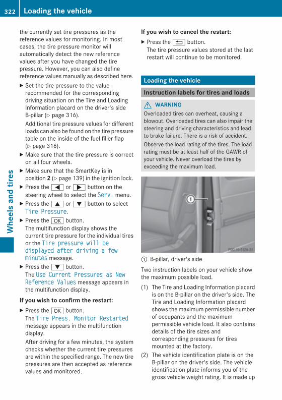
the currently set tire pressures as thereference values for monitoring. In mostcases, the tire pressure monitor willautomatically detect the new referencevalues after you have changed the tirepressure. However, you can also definereference values manually as described here.X Set the tire pressure to the valuerecommended for the correspondingdriving situation on the Tire and LoadingInformation placard on the driver's sideB-pillar (Y page 316).Additional tire pressure values for differentloads can also be found on the tire pressuretable on the inside of the fuel filler flap(Y page 316).
X Make sure that the tire pressure is correcton all four wheels.
X Make sure that the SmartKey is inposition 2 (Y page 139) in the ignition lock.
X Press the= or; button on thesteering wheel to select the Serv.Serv. menu.
X Press the9 or: button to selectTire PressureTire Pressure.
X Press thea button.The multifunction display shows thecurrent tire pressure for the individual tiresor the Tire pressure will beTire pressure will bedisplayed after driving a fewdisplayed after driving a fewminutesminutes message.
X Press the: button.The Use Current Pressures as NewUse Current Pressures as NewReference ValuesReference Values message appears inthe multifunction display.
If you wish to confirm the restart:X Press thea button.The Tire Press. Monitor RestartedTire Press. Monitor Restartedmessage appears in the multifunctiondisplay.After driving for a few minutes, the systemchecks whether the current tire pressuresare within the specified range. The new tirepressures are then accepted as referencevalues and monitored.
If you wish to cancel the restart:X Press the% button.The tire pressure values stored at the lastrestart will continue to be monitored.
Loading the vehicle
Instruction labels for tires and loads
G WARNINGOverloaded tires can overheat, causing ablowout. Overloaded tires can also impair thesteering and driving characteristics and leadto brake failure. There is a risk of accident.Observe the load rating of the tires. The loadrating must be at least half of the GAWR ofyour vehicle. Never overload the tires byexceeding the maximum load.
: B-pillar, driver's side
Two instruction labels on your vehicle showthe maximum possible load.(1) The Tire and Loading Information placard
is on the B-pillar on the driver's side. TheTire and Loading Information placardshows themaximum permissible numberof occupants and the maximumpermissible vehicle load. It also containsdetails of the tire sizes andcorresponding pressures for tiresmounted at the factory.
(2) The vehicle identification plate is on theB-pillar on the driver's side. The vehicleidentification plate informs you of thegross vehicle weight rating. It is made up
322 Loading the vehicleWheelsandtires
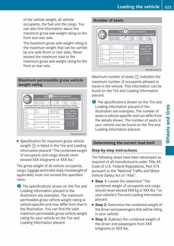
of the vehicle weight, all vehicleoccupants, the fuel and the cargo. Youcan also find information about themaximum gross axle weight rating on thefront and rear axle.The maximum gross axle weight rating isthe maximum weight that can be carriedby one axle (front or rear axle). Neverexceed the maximum load or themaximum gross axle weight rating for thefront or rear axle.
Maximum permissible gross vehicleweight rating
X Specification for maximum gross vehicleweight: is listed in the Tire and LoadingInformation placard: "The combined weightof occupants and cargo should neverexceed XXX kilograms or XXX lbs."
The gross weight of all vehicle occupants,cargo, luggage and trailer load/noseweight (ifapplicable) must not exceed the specifiedvalue.
i The specifications shown on the Tire andLoading Information placard in theillustration are examples. The maximumpermissible gross vehicle weight rating isvehicle-specific and may differ from that inthe illustration. You can find the validmaximum permissible gross vehicle weightrating for your vehicle on the Tire andLoading Information placard.
Number of seats
Maximum number of seats: indicates themaximum number of occupants allowed totravel in the vehicle. This information can befound on the Tire and Loading Informationplacard.
i The specifications shown on the Tire andLoading Information placard in theillustration are examples. The number ofseats is vehicle-specific and can differ fromthe details shown. The number of seats inyour vehicle can be found on the Tire andLoading Information placard.
Determining the correct load limit
Step-by-step instructionsThe following steps have been developed asrequired of all manufacturers under Title 49,Code of U.S. Federal Regulations, Part 575pursuant to the "National Traffic and MotorVehicle Safety Act of 1966".X Step 1: Locate the statement "Thecombined weight of occupants and cargoshould never exceed XXX kg or XXX lbs." onyour vehicle’s Tire and Loading Informationplacard.
X Step 2: Determine the combined weight ofthe driver and passengers that will be ridingin your vehicle.
X Step 3: Subtract the combined weight ofthe driver and passengers from XXXkilograms or XXX lbs.
Loading the vehicle 323
Wheelsandtires
Z
X Step 4: The resulting figure equals theavailable amount of cargo and luggage loadcapacity. For example, if the "XXX" amountequals 1400 lbs and there will be five 150-pound passengers in your vehicle, theamount of available cargo and luggage loadcapacity is 650 lbs (1400 – 750 (5 x 150)= 650 lbs).
X Step 5:Determine the combined weight ofluggage and cargo being loaded on thevehicle. That weight may not safely exceedthe available cargo and luggage loadcapacity calculated in step 4.
X Step 6 (if applicable): If your vehicle willbe towing a trailer, load from your trailerwill be transferred to your vehicle. Thisreduces the available cargo and luggageload capacity of your vehicle(Y page 352).
324 Loading the vehicleWheelsandtires
Example: steps 1 to 3The following table shows examples on how to calculate total and cargo load capacities withvarying seating configurations and number and size of occupants. The following examples usea maximum load of 1500 lbs (680 kg). This is for illustration purposes only.Make sure youare using the actual load limit for your vehicle stated on your vehicle's Tire and LoadingInformation placard (Y page 322).The higher the weight of all the occupants, the smaller the maximum load for luggage.Additional information when towing a trailer (Y page 352).Step 1
Example 1 Example 2 Example 3
Combined maximumweight of occupants andcargo (data from the Tireand Loading Informationplacard)
1500 lbs (680 kg) 1500 lbs (680 kg) 1500 lbs (680 kg)
Step 2
Example 1 Example 2 Example 3
Number ofpeople in thevehicle (driverandoccupants)
5 3 1
Distribution ofthe occupants
Front: 2Rear: 3
Front: 1Rear: 2
Front: 1
Weight of theoccupants
Occupant 1: 150 lbs(68 kg)Occupant 2: 180 lbs(82 kg)Occupant 3: 160 lbs(73 kg)Occupant 4: 140 lbs(63 kg)Occupant 5: 120 lbs(54 kg)
Occupant 1: 200 lbs(91 kg)Occupant 2: 190 lbs(86 kg)Occupant 3: 150 lbs(68 kg)
Occupant 1:150 lbs (68 kg)
Gross weightof alloccupants
750 lbs (340 kg) 540 lbs (245 kg) 150 lbs (68 kg)
Loading the vehicle 325
Wheelsandtires
Z
Step 3
Example 1 Example 2 Example 3
Permissible load(maximum grossvehicle weightrating from the Tireand LoadingInformationplacard minus thegross weight of alloccupants)
1500 lbs (680 kg)Ò750 lbs (340 kg) =750 lbs (340 kg)
1500 lbs (680 kg)Ò540 lbs (245 kg) =960 lbs (435 kg)
1500 lbs (680 kg)Ò150 lbs (68 kg) =1350 lbs (612 kg)
Vehicle identification plateEven if you have calculated the total loadcarefully, you should still make sure that thegross vehicle weight rating and the gross axleweight rating are not exceeded. Details canbe found on the vehicle identification plate onthe B-pillar on the driver's side of the vehicle(Y page 322).Permissible gross vehicle weight: thegross weight of the vehicle, all passengers,load and trailer load/noseweight (ifapplicable) must not exceed the permissiblegross vehicle weight.Gross axle weight rating: the maximumpermissible weight that can be carried by oneaxle (front or rear axle).To ensure that your vehicle does not exceedthe maximum permissible values (grossvehicle weight and maximum gross axleweight rating), have your loaded vehicle(including driver, occupants, cargo, and fulltrailer load if applicable) weighed on asuitable vehicle weighbridge.
Trailer load/noseweightThe trailer load/noseweight affects the grossweight of the vehicle. If a trailer is attached,the trailer load/noseweight is included in theload along with occupants and luggage. Thetrailer load/noseweight is usually
approximately 10% of the gross weight of thetrailer and its load.Only use a trailer tow hitch that has beenapproved for your vehicle by Mercedes-Benz.Comply with the manufacturer's operatinginstructions for operation, care andmaintenance.
Uniform Tire Quality GradingStandards
Overview of Tire Quality GradingStandards
Uniform Tire Quality Grading Standards areU.S. government specifications. Theirpurpose is to provide drivers with uniformreliable information on tire performance data.Tire manufacturers have to grade tires usingthree performance factors:: tread weargrade,; traction grade and= temperaturegrade. These regulations do not apply to
326 Uniform Tire Quality Grading StandardsWheelsandtires
Canada. Nevertheless, all tires sold in NorthAmerica are provided with the correspondingquality grading markings on the sidewall ofthe tire.Where applicable, the tire gradinginformation can be found on the tire sidewallbetween the tread shoulder and maximumtire width.Example:RTreadwear grade: 200RTraction grade: AARTemperature grade: AAll passenger car tires must conform to thestatutory safety requirements in addition tothese grades.
i The actual values for tires are vehicle-specific and may deviate from the values inthe illustration.
TreadwearThe treadwear grade is a comparative ratingbased on thewear rate of the tire when testedunder controlled conditions on a specifiedU.S. government course. For example, a tiregraded 150 would wear one and one-halftimes as well on the government test track asa tire graded 100.The relative performance of tires dependsupon the actual conditions of their use,however, and may depart significantly fromthe norm, due to variations in driving habits,service practices and differences in roadcharacteristics and climate conditions.
Traction
G WARNINGThe traction grade assigned to this tire isbased on straight-ahead braking tractiontests, and does not include acceleration,cornering, hydroplaning, or peak tractioncharacteristics.
! Avoid wheelspin. This can lead to damageto the drive train.
The traction grades, from highest to lowest,are AA, A, B, and C. Those grades representthe tire's ability to stop on a wet surface asmeasured under controlled conditions onspecified government test surfaces of asphaltand concrete. A tire marked C may have poortraction performance.The safe speed on a wet, snow covered or icyroad is always lower than on dry roadsurfaces.You should pay special attention to roadconditions when temperatures are aroundfreezing point.Mercedes-Benz recommends a minimumtread depth ofã in (4 mm) on all four wintertires. Observe the legally required minimumtire tread depth (Y page 313).Winter tires canreduce the braking distance on snow-coveredsurfaces in comparison with summer tires.The braking distance is still much further thanon surfaces that are not icy or covered withsnow. Take appropriate care when driving.Further information on winter tires (M+Stires) (Y page 314).
Temperature
G WARNINGThe temperature grade for this tire isestablished for a tire that is properly inflatedand not overloaded. Excessive speed,underinflation, or excessive loading, eitherseparately or in combination, can causeexcessive heat build-up and possible tirefailure.
The temperature grades are A (the highest),B, and C. These represent the tire'sresistance to the generation of heat and itsability to dissipate heat when tested undercontrolled conditions on a specified indoorlaboratory test wheel. Sustained hightemperature can cause thematerial of the tireto degenerate and reduce tire life, and
Uniform Tire Quality Grading Standards 327
Wheelsandtires
Z
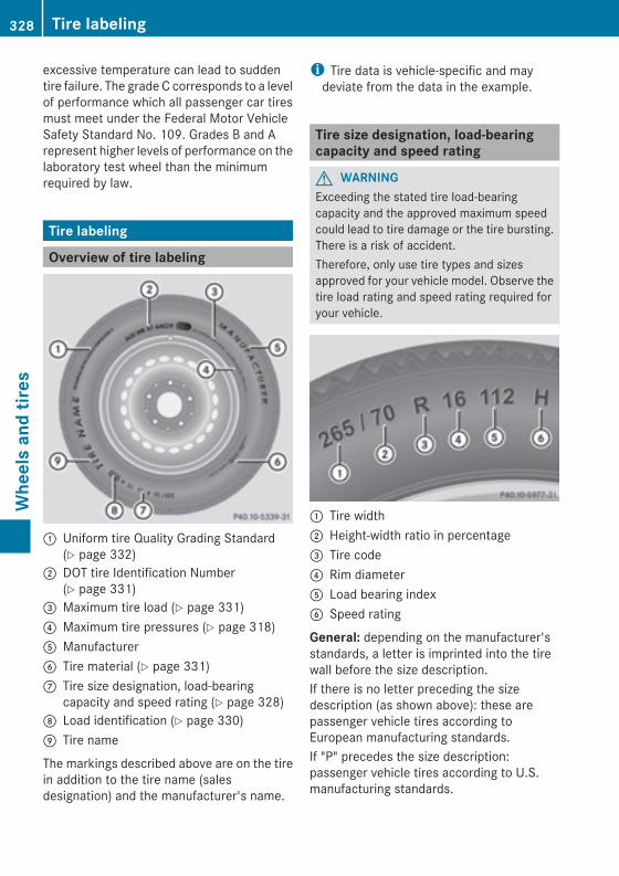
excessive temperature can lead to suddentire failure. The grade C corresponds to a levelof performance which all passenger car tiresmust meet under the Federal Motor VehicleSafety Standard No. 109. Grades B and Arepresent higher levels of performance on thelaboratory test wheel than the minimumrequired by law.
Tire labeling
Overview of tire labeling
: Uniform tire Quality Grading Standard(Y page 332)
; DOT tire Identification Number(Y page 331)
= Maximum tire load (Y page 331)? Maximum tire pressures (Y page 318)A ManufacturerB Tire material (Y page 331)C Tire size designation, load-bearing
capacity and speed rating (Y page 328)D Load identification (Y page 330)E Tire name
The markings described above are on the tirein addition to the tire name (salesdesignation) and the manufacturer's name.
i Tire data is vehicle-specific and maydeviate from the data in the example.
Tire size designation, load-bearingcapacity and speed rating
G WARNINGExceeding the stated tire load-bearingcapacity and the approved maximum speedcould lead to tire damage or the tire bursting.There is a risk of accident.Therefore, only use tire types and sizesapproved for your vehicle model. Observe thetire load rating and speed rating required foryour vehicle.
: Tire width; Height-width ratio in percentage= Tire code? Rim diameterA Load bearing indexB Speed rating
General: depending on the manufacturer'sstandards, a letter is imprinted into the tirewall before the size description.If there is no letter preceding the sizedescription (as shown above): these arepassenger vehicle tires according toEuropean manufacturing standards.If "P" precedes the size description:passenger vehicle tires according to U.S.manufacturing standards.
328 Tire labelingWheelsandtires
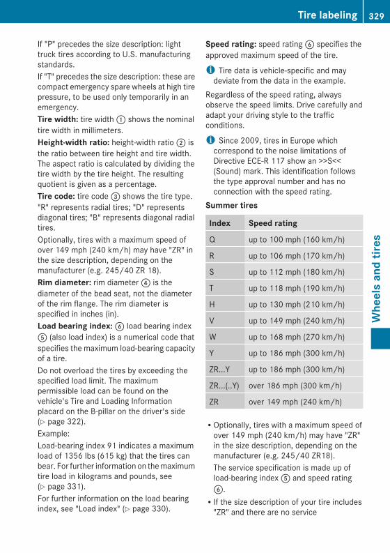
If "P" precedes the size description: lighttruck tires according to U.S. manufacturingstandards.If "T" precedes the size description: these arecompact emergency spare wheels at high tirepressure, to be used only temporarily in anemergency.Tire width: tire width: shows the nominaltire width in millimeters.Height-width ratio: height-width ratio; isthe ratio between tire height and tire width.The aspect ratio is calculated by dividing thetire width by the tire height. The resultingquotient is given as a percentage.Tire code: tire code= shows the tire type."R" represents radial tires; "D" representsdiagonal tires; "B" represents diagonal radialtires.Optionally, tires with a maximum speed ofover 149 mph (240 km/h) may have "ZR" inthe size description, depending on themanufacturer (e.g. 245/40 ZR 18).Rim diameter: rim diameter? is thediameter of the bead seat, not the diameterof the rim flange. The rim diameter isspecified in inches (in).Load bearing index:B load bearing indexA (also load index) is a numerical code thatspecifies the maximum load-bearing capacityof a tire.Do not overload the tires by exceeding thespecified load limit. The maximumpermissible load can be found on thevehicle's Tire and Loading Informationplacard on the B-pillar on the driver's side(Y page 322).Example:Load-bearing index 91 indicates a maximumload of 1356 lbs (615 kg) that the tires canbear. For further information on themaximumtire load in kilograms and pounds, see(Y page 331).For further information on the load bearingindex, see "Load index" (Y page 330).
Speed rating: speed ratingB specifies theapproved maximum speed of the tire.
i Tire data is vehicle-specific and maydeviate from the data in the example.
Regardless of the speed rating, alwaysobserve the speed limits. Drive carefully andadapt your driving style to the trafficconditions.
i Since 2009, tires in Europe whichcorrespond to the noise limitations ofDirective ECE-R 117 show an >>S<<(Sound) mark. This identification followsthe type approval number and has noconnection with the speed rating.
Summer tires
Index Speed rating
Q up to 100 mph (160 km/h)
R up to 106 mph (170 km/h)
S up to 112 mph (180 km/h)
T up to 118 mph (190 km/h)
H up to 130 mph (210 km/h)
V up to 149 mph (240 km/h)
W up to 168 mph (270 km/h)
Y up to 186 mph (300 km/h)
ZR...Y up to 186 mph (300 km/h)
ZR...(..Y) over 186 mph (300 km/h)
ZR over 149 mph (240 km/h)
ROptionally, tires with a maximum speed ofover 149 mph (240 km/h) may have "ZR"in the size description, depending on themanufacturer (e.g. 245/40 ZR18).The service specification is made up ofload-bearing indexA and speed ratingB.RIf the size description of your tire includes"ZR" and there are no service
Tire labeling 329
Wheelsandtires
Z
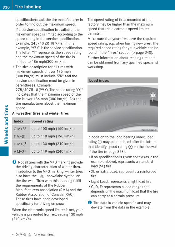
specifications, ask the tire manufacturer inorder to find out the maximum speed.If a service specification is available, themaximum speed is limited according to thespeed rating in the service specification.Example: 245/40 ZR 18 97 Y. In thisexample, "97 Y" is the service specification.The letter "Y" represents the speed ratingand the maximum speed of the tire islimited to 186 mph(300 km/h).RThe size description for all tires withmaximum speeds of over 186 mph(300 km/h) must include "ZR" and theservice specification must be given inparentheses. Example:275/40 ZR 18 (99 Y). The speed rating "(Y)"indicates that the maximum speed of thetire is over 186 mph (300 km/h). Ask thetire manufacturer about the maximumspeed.
All-weather tires and winter tires
Index Speed rating
Q M+S4 up to 100 mph (160 km/h)
T M+S4 up to 118 mph (190 km/h)
H M+S4 up to 130 mph (210 km/h)
V M+S4 up to 149 mph (240 km/h)
i Not all tires with theM+Smarking providethe driving characteristics of winter tires.In addition to theM+Smarking, winter tiresalso have thei snowflake symbol onthe tire wall. Tires with this marking fulfillthe requirements of the RubberManufacturers Association (RMA) and theRubber Association of Canada (RAC).These tires have been developedspecifically for driving on snow.
When the electronic speed limiter is set, yourvehicle is prevented from exceeding 130mph(210 km/h).
The speed rating of tires mounted at thefactory may be higher than the maximumspeed that the electronic speed limiterpermits.Make sure that your tires have the requiredspeed rating, e.g. when buying new tires. Therequired speed rating for your vehicle can befound in the "Tires" section (Y page 340).Further information about reading tire datacan be obtained from any qualified specialistworkshop.
Load index
In addition to the load bearing index, loadrating: may be imprinted after the lettersthat identify speed ratingB on the sidewallof the tire (Y page 328).RIf no specification is given: no text (as in theexample above), represents a standardload (SL) tireRXL or Extra Load: represents a reinforcedtireRLight Load: represents a light load tireRC, D, E: represents a load range thatdepends on the maximum load that the tirecan carry at a certain pressure
i Tire data is vehicle-specific and maydeviate from the data in the example.
4 Or M+Si for winter tires.
330 Tire labelingWheelsandtires
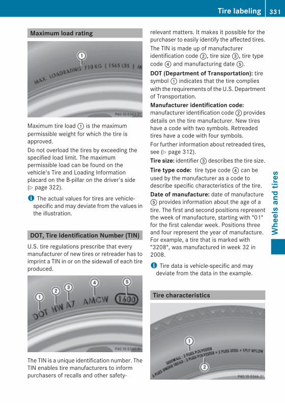
Maximum load rating
Maximum tire load: is the maximumpermissible weight for which the tire isapproved.Do not overload the tires by exceeding thespecified load limit. The maximumpermissible load can be found on thevehicle's Tire and Loading Informationplacard on the B-pillar on the driver's side(Y page 322).
i The actual values for tires are vehicle-specific and may deviate from the values inthe illustration.
DOT, Tire Identification Number (TIN)U.S. tire regulations prescribe that everymanufacturer of new tires or retreader has toimprint a TIN in or on the sidewall of each tireproduced.
The TIN is a unique identification number. TheTIN enables tire manufacturers to informpurchasers of recalls and other safety-
relevant matters. It makes it possible for thepurchaser to easily identify the affected tires.The TIN is made up of manufactureridentification code;, tire size=, tire typecode? and manufacturing dateA.DOT (Department of Transportation): tiresymbol: indicates that the tire complieswith the requirements of theU.S. Departmentof Transportation.Manufacturer identification code:manufacturer identification code; providesdetails on the tire manufacturer. New tireshave a code with two symbols. Retreadedtires have a code with four symbols.For further information about retreaded tires,see (Y page 312).Tire size: identifier= describes the tire size.Tire type code: tire type code? can beused by the manufacturer as a code todescribe specific characteristics of the tire.Date of manufacture: date of manufactureA provides information about the age of atire. The first and second positions representthe week of manufacture, starting with "01"for the first calendar week. Positions threeand four represent the year of manufacture.For example, a tire that is marked with"3208", was manufactured in week 32 in2008.
i Tire data is vehicle-specific and maydeviate from the data in the example.
Tire characteristics
Tire labeling 331
Wheelsandtires
Z
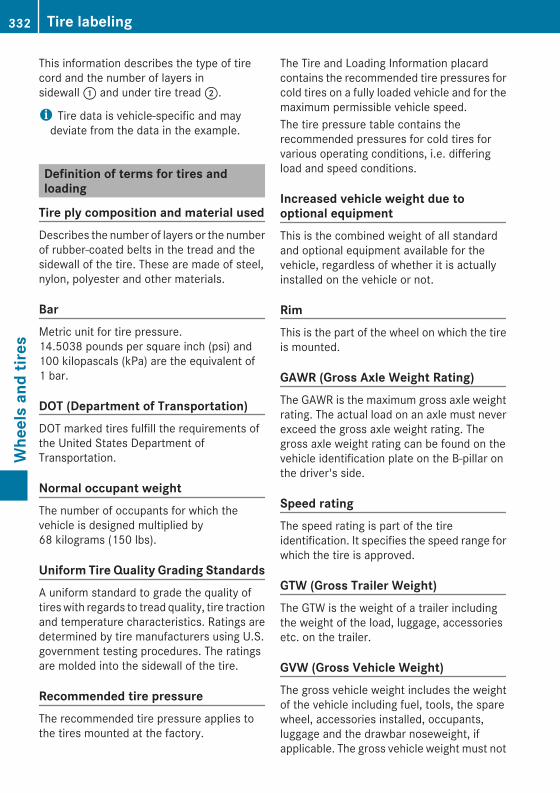
This information describes the type of tirecord and the number of layers insidewall: and under tire tread;.
i Tire data is vehicle-specific and maydeviate from the data in the example.
Definition of terms for tires andloading
Tire ply composition and material usedDescribes the number of layers or the numberof rubber-coated belts in the tread and thesidewall of the tire. These are made of steel,nylon, polyester and other materials.
BarMetric unit for tire pressure.14.5038 pounds per square inch (psi) and100 kilopascals (kPa) are the equivalent of1 bar.
DOT (Department of Transportation)DOT marked tires fulfill the requirements ofthe United States Department ofTransportation.
Normal occupant weightThe number of occupants for which thevehicle is designed multiplied by68 kilograms (150 lbs).
Uniform Tire Quality Grading StandardsA uniform standard to grade the quality oftireswith regards to tread quality, tire tractionand temperature characteristics. Ratings aredetermined by tire manufacturers using U.S.government testing procedures. The ratingsare molded into the sidewall of the tire.
Recommended tire pressureThe recommended tire pressure applies tothe tires mounted at the factory.
The Tire and Loading Information placardcontains the recommended tire pressures forcold tires on a fully loaded vehicle and for themaximum permissible vehicle speed.The tire pressure table contains therecommended pressures for cold tires forvarious operating conditions, i.e. differingload and speed conditions.
Increased vehicle weight due tooptional equipmentThis is the combined weight of all standardand optional equipment available for thevehicle, regardless of whether it is actuallyinstalled on the vehicle or not.
RimThis is the part of the wheel on which the tireis mounted.
GAWR (Gross Axle Weight Rating)The GAWR is the maximum gross axle weightrating. The actual load on an axle must neverexceed the gross axle weight rating. Thegross axle weight rating can be found on thevehicle identification plate on the B-pillar onthe driver's side.
Speed ratingThe speed rating is part of the tireidentification. It specifies the speed range forwhich the tire is approved.
GTW (Gross Trailer Weight)The GTW is the weight of a trailer includingthe weight of the load, luggage, accessoriesetc. on the trailer.
GVW (Gross Vehicle Weight)The gross vehicle weight includes the weightof the vehicle including fuel, tools, the sparewheel, accessories installed, occupants,luggage and the drawbar noseweight, ifapplicable. The gross vehicle weight must not
332 Tire labelingWheelsandtires
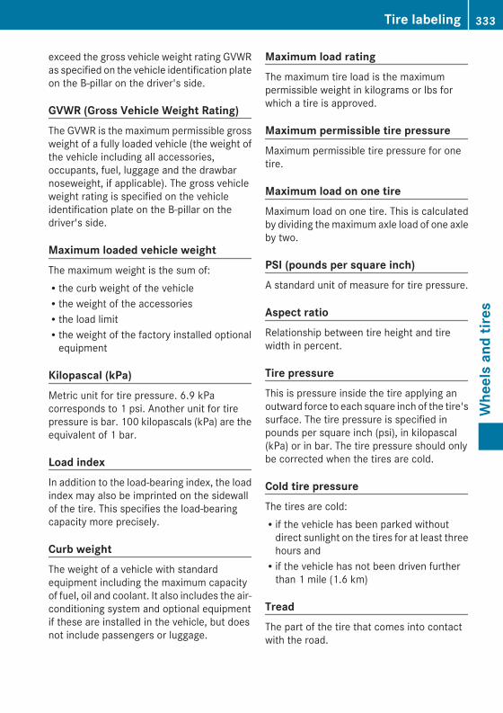
exceed the gross vehicle weight rating GVWRas specified on the vehicle identification plateon the B-pillar on the driver's side.
GVWR (Gross Vehicle Weight Rating)The GVWR is the maximum permissible grossweight of a fully loaded vehicle (the weight ofthe vehicle including all accessories,occupants, fuel, luggage and the drawbarnoseweight, if applicable). The gross vehicleweight rating is specified on the vehicleidentification plate on the B-pillar on thedriver's side.
Maximum loaded vehicle weightThe maximum weight is the sum of:Rthe curb weight of the vehicleRthe weight of the accessoriesRthe load limitRthe weight of the factory installed optionalequipment
Kilopascal (kPa)Metric unit for tire pressure. 6.9 kPacorresponds to 1 psi. Another unit for tirepressure is bar. 100 kilopascals (kPa) are theequivalent of 1 bar.
Load indexIn addition to the load-bearing index, the loadindex may also be imprinted on the sidewallof the tire. This specifies the load-bearingcapacity more precisely.
Curb weightThe weight of a vehicle with standardequipment including the maximum capacityof fuel, oil and coolant. It also includes the air-conditioning system and optional equipmentif these are installed in the vehicle, but doesnot include passengers or luggage.
Maximum load ratingThe maximum tire load is the maximumpermissible weight in kilograms or lbs forwhich a tire is approved.
Maximum permissible tire pressureMaximum permissible tire pressure for onetire.
Maximum load on one tireMaximum load on one tire. This is calculatedby dividing themaximum axle load of one axleby two.
PSI (pounds per square inch)A standard unit of measure for tire pressure.
Aspect ratioRelationship between tire height and tirewidth in percent.
Tire pressureThis is pressure inside the tire applying anoutward force to each square inch of the tire'ssurface. The tire pressure is specified inpounds per square inch (psi), in kilopascal(kPa) or in bar. The tire pressure should onlybe corrected when the tires are cold.
Cold tire pressureThe tires are cold:Rif the vehicle has been parked withoutdirect sunlight on the tires for at least threehours andRif the vehicle has not been driven furtherthan 1 mile (1.6 km)
TreadThe part of the tire that comes into contactwith the road.
Tire labeling 333
Wheelsandtires
Z
BeadThe tire bead ensures that the tire sitssecurely on the wheel. There are several steelwires in the bead to prevent the tire fromcoming loose from the wheel rim.
SidewallThe part of the tire between the tread and thebead.
Weight of optional extrasThe combined weight of those optional extrasthat weigh more than the replaced standardparts and more than 2.3 kg (5 lbs). Theseoptional extras, such as high-performancebrakes, level control, a roof rack or a high-performance battery, are not included in thecurb weight and the weight of theaccessories.
TIN (Tire Identification Number)This is a unique identifier which can be usedby a tire manufacturer to identify tires, forexample for a product recall, and thus identifythe purchasers. The TIN is made up of themanufacturer's identity code, tire size, tiretype code and the manufacturing date.
Load bearing indexThe load bearing index (also load index) is acode that contains themaximum load bearingcapacity of a tire.
TractionTraction is the result of friction between thetires and the road surface.
TWR (Tongue Weight Rating)The TWR specifies the maximum permissibleweight that the ball coupling of the trailer towhitch can support.
Treadwear indicatorsNarrow bars (tread wear bars) that aredistributed over the tire tread. If the tire treadis level with the bars, the wear limit ofá in(1.6 mm) has been reached.
Occupant distributionThe distribution of occupants in a vehicle attheir designated seating positions.
Total load limitNominal load and luggage load plus 150 lbs(68 kg) multiplied by the number of seats inthe vehicle.
Changing a wheel
Flat tireThe "Breakdown assistance" section(Y page 298) contains information and noteson how to deal with a flat tire.
Rotating the wheels
G WARNINGRotate front and rear wheels only if the tiresare of the same dimension.If your vehicle is equipped with mixed-sizetires (different tire dimensions front vs. rear),tire rotation is not possible.
G WARNINGHave the tightening torque checked afterchanging a wheel. The wheels could comeloose if they are not tightened to a torque of96 lb-ft (130 Nm).Only use genuine Mercedes-Benz wheel boltsspecified for your vehicle's rims.
! On vehicles equipped with a tire pressuremonitor, electronic components arelocated in the wheel.
334 Changing a wheelWheelsandtires
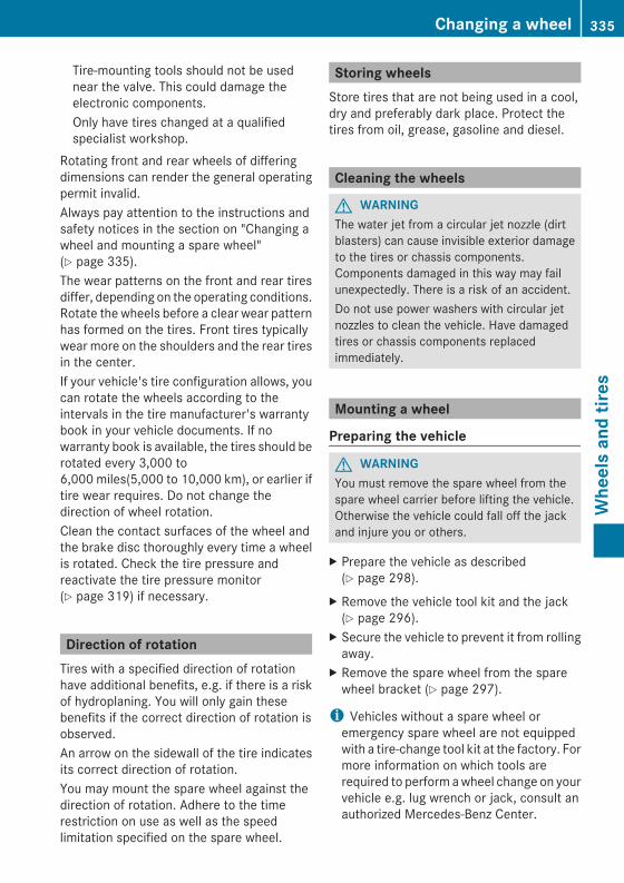
Tire-mounting tools should not be usednear the valve. This could damage theelectronic components.Only have tires changed at a qualifiedspecialist workshop.
Rotating front and rear wheels of differingdimensions can render the general operatingpermit invalid.Always pay attention to the instructions andsafety notices in the section on "Changing awheel and mounting a spare wheel"(Y page 335).The wear patterns on the front and rear tiresdiffer, depending on the operating conditions.Rotate the wheels before a clear wear patternhas formed on the tires. Front tires typicallywear more on the shoulders and the rear tiresin the center.If your vehicle's tire configuration allows, youcan rotate the wheels according to theintervals in the tire manufacturer's warrantybook in your vehicle documents. If nowarranty book is available, the tires should berotated every 3,000 to6,000 miles(5,000 to 10,000 km), or earlier iftire wear requires. Do not change thedirection of wheel rotation.Clean the contact surfaces of the wheel andthe brake disc thoroughly every time a wheelis rotated. Check the tire pressure andreactivate the tire pressure monitor(Y page 319) if necessary.
Direction of rotationTires with a specified direction of rotationhave additional benefits, e.g. if there is a riskof hydroplaning. You will only gain thesebenefits if the correct direction of rotation isobserved.An arrow on the sidewall of the tire indicatesits correct direction of rotation.You may mount the spare wheel against thedirection of rotation. Adhere to the timerestriction on use as well as the speedlimitation specified on the spare wheel.
Storing wheelsStore tires that are not being used in a cool,dry and preferably dark place. Protect thetires from oil, grease, gasoline and diesel.
Cleaning the wheels
G WARNINGThe water jet from a circular jet nozzle (dirtblasters) can cause invisible exterior damageto the tires or chassis components.Components damaged in this way may failunexpectedly. There is a risk of an accident.Do not use power washers with circular jetnozzles to clean the vehicle. Have damagedtires or chassis components replacedimmediately.
Mounting a wheel
Preparing the vehicle
G WARNINGYou must remove the spare wheel from thespare wheel carrier before lifting the vehicle.Otherwise the vehicle could fall off the jackand injure you or others.
X Prepare the vehicle as described(Y page 298).
X Remove the vehicle tool kit and the jack(Y page 296).
X Secure the vehicle to prevent it from rollingaway.
X Remove the spare wheel from the sparewheel bracket (Y page 297).
i Vehicles without a spare wheel oremergency spare wheel are not equippedwith a tire-change tool kit at the factory. Formore information on which tools arerequired to perform awheel change on yourvehicle e.g. lug wrench or jack, consult anauthorized Mercedes-Benz Center.
Changing a wheel 335
Wheelsandtires
Z
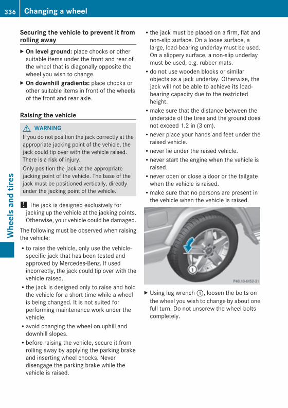
Securing the vehicle to prevent it fromrolling awayX On level ground: place chocks or othersuitable items under the front and rear ofthe wheel that is diagonally opposite thewheel you wish to change.
X On downhill gradients: place chocks orother suitable items in front of the wheelsof the front and rear axle.
Raising the vehicle
G WARNINGIf you do not position the jack correctly at theappropriate jacking point of the vehicle, thejack could tip over with the vehicle raised.There is a risk of injury.Only position the jack at the appropriatejacking point of the vehicle. The base of thejack must be positioned vertically, directlyunder the jacking point of the vehicle.
! The jack is designed exclusively forjacking up the vehicle at the jacking points.Otherwise, your vehicle could be damaged.
The following must be observed when raisingthe vehicle:Rto raise the vehicle, only use the vehicle-specific jack that has been tested andapproved by Mercedes-Benz. If usedincorrectly, the jack could tip over with thevehicle raised.Rthe jack is designed only to raise and holdthe vehicle for a short time while a wheelis being changed. It is not suited forperforming maintenance work under thevehicle.Ravoid changing the wheel on uphill anddownhill slopes.Rbefore raising the vehicle, secure it fromrolling away by applying the parking brakeand inserting wheel chocks. Neverdisengage the parking brake while thevehicle is raised.
Rthe jack must be placed on a firm, flat andnon-slip surface. On a loose surface, alarge, load-bearing underlay must be used.On a slippery surface, a non-slip underlaymust be used, e.g. rubber mats.Rdo not use wooden blocks or similarobjects as a jack underlay. Otherwise, thejack will not be able to achieve its load-bearing capacity due to the restrictedheight.Rmake sure that the distance between theunderside of the tires and the ground doesnot exceed 1.2 in (3 cm).Rnever place your hands and feet under theraised vehicle.Rnever lie under the raised vehicle.Rnever start the engine when the vehicle israised.Rnever open or close a door or the tailgatewhen the vehicle is raised.Rmake sure that no persons are present inthe vehicle when the vehicle is raised.
X Using lug wrench:, loosen the bolts onthe wheel you wish to change by about onefull turn. Do not unscrew the wheel boltscompletely.
336 Changing a wheelWheelsandtires
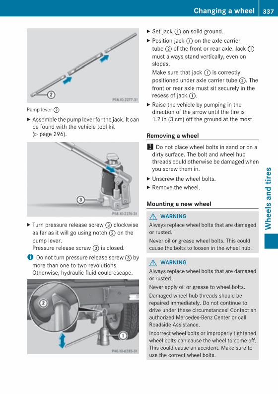
Pump lever;
X Assemble the pump lever for the jack. It canbe found with the vehicle tool kit(Y page 296).
X Turn pressure release screw= clockwiseas far as it will go using notch; on thepump lever.Pressure release screw= is closed.i Do not turn pressure release screw= bymore than one to two revolutions.Otherwise, hydraulic fluid could escape.
X Set jack: on solid ground.X Position jack: on the axle carriertube; of the front or rear axle. Jack:must always stand vertically, even onslopes.Make sure that jack: is correctlypositioned under axle carrier tube;. Thefront or rear axle must sit securely in therecess of jack:.
X Raise the vehicle by pumping in thedirection of the arrow until the tire is1.2 in (3 cm) off the ground at the most.
Removing a wheel! Do not place wheel bolts in sand or on adirty surface. The bolt and wheel hubthreads could otherwise be damaged whenyou screw them in.
X Unscrew the wheel bolts.X Remove the wheel.
Mounting a new wheel
G WARNINGAlways replace wheel bolts that are damagedor rusted.Never oil or grease wheel bolts. This couldcause the bolts to loosen in the wheel hub.
G WARNINGAlways replace wheel bolts that are damagedor rusted.Never apply oil or grease to wheel bolts.Damaged wheel hub threads should berepaired immediately. Do not continue todrive under these circumstances! Contact anauthorized Mercedes-Benz Center or callRoadside Assistance.Incorrect wheel bolts or improperly tightenedwheel bolts can cause the wheel to come off.This could cause an accident. Make sure touse the correct wheel bolts.
Changing a wheel 337
Wheelsandtires
Z
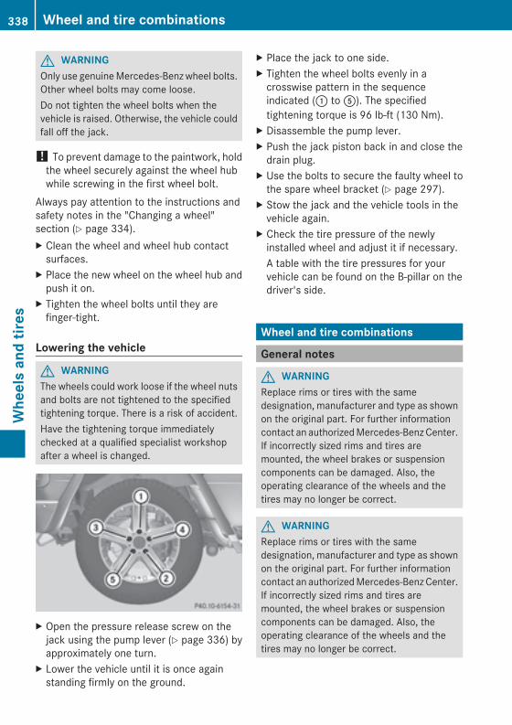
G WARNINGOnly use genuineMercedes-Benz wheel bolts.Other wheel bolts may come loose.Do not tighten the wheel bolts when thevehicle is raised. Otherwise, the vehicle couldfall off the jack.
! To prevent damage to the paintwork, holdthe wheel securely against the wheel hubwhile screwing in the first wheel bolt.
Always pay attention to the instructions andsafety notes in the "Changing a wheel"section (Y page 334).X Clean the wheel and wheel hub contactsurfaces.
X Place the new wheel on the wheel hub andpush it on.
X Tighten the wheel bolts until they arefinger-tight.
Lowering the vehicle
G WARNINGThe wheels could work loose if the wheel nutsand bolts are not tightened to the specifiedtightening torque. There is a risk of accident.Have the tightening torque immediatelychecked at a qualified specialist workshopafter a wheel is changed.
X Open the pressure release screw on thejack using the pump lever (Y page 336) byapproximately one turn.
X Lower the vehicle until it is once againstanding firmly on the ground.
X Place the jack to one side.X Tighten the wheel bolts evenly in acrosswise pattern in the sequenceindicated (: toA). The specifiedtightening torque is 96 lb-ft (130 Nm).
X Disassemble the pump lever.X Push the jack piston back in and close thedrain plug.
X Use the bolts to secure the faulty wheel tothe spare wheel bracket (Y page 297).
X Stow the jack and the vehicle tools in thevehicle again.
X Check the tire pressure of the newlyinstalled wheel and adjust it if necessary.A table with the tire pressures for yourvehicle can be found on the B-pillar on thedriver's side.
Wheel and tire combinations
General notes
G WARNINGReplace rims or tires with the samedesignation, manufacturer and type as shownon the original part. For further informationcontact an authorizedMercedes-BenzCenter.If incorrectly sized rims and tires aremounted, the wheel brakes or suspensioncomponents can be damaged. Also, theoperating clearance of the wheels and thetires may no longer be correct.
G WARNINGReplace rims or tires with the samedesignation, manufacturer and type as shownon the original part. For further informationcontact an authorizedMercedes-BenzCenter.If incorrectly sized rims and tires aremounted, the wheel brakes or suspensioncomponents can be damaged. Also, theoperating clearance of the wheels and thetires may no longer be correct.
338 Wheel and tire combinationsWheelsandtires
G WARNINGIf you notice sudden significant vibrations orunusual handling performance or if yoususpect that damage has occurred to thevehicle, you should activate the hazardwarning lamps, gently reduce speed andcarefully head for an area that is located at asafe distance from the road.Check the tires and the underside of thevehicle for damage. If the vehicle seemsunsafe, have the vehicle towed away to thenearest Mercedes-Benz Center or tire dealerto be repaired.
G WARNINGDo not drive with a flat tire. A flat tire affectsthe ability to steer or brake the vehicle. Youmight lose control of the vehicle. Continueddriving with a flat tire or driving at high speedwith a flat tire will cause excessive heat build-up and possibly a fire.
! For safety reasons, Mercedes-Benzrecommends that you only use tires,wheels and accessories which have beenapproved by Mercedes-Benz specificallyfor your vehicle. These tires have beenspecially adapted for use with the drivingsafety systems, such as ABS or ESP®.Only use tires, wheels or accessoriestested and approved by Mercedes-Benz.Certain characteristics, e.g. handling,vehicle noise emissions or fuelconsumption, may otherwise be adverselyaffected. In addition, when driving with aload, tire dimension variations could causethe tires to come into contact with thebodywork and axle components. This couldresult in damage to the tires or the vehicle.Mercedes-Benz accepts no liability fordamage resulting from the use of tires,wheels or accessories other than thosetested and approved.Further information about wheels, tires andapproved combinations can be obtained
from any authorized Mercedes-BenzCenter.
i The recommended pressures for variousoperating conditions can be found:Ron the Tire and Loading Informationplacard with the recommended tirepressures on the B-pillar on the driver'ssideRin the tire pressure table on the inside ofthe fuel filler flap
Observe the notes on recommended tirepressure under various operatingconditions.Check tire pressures regularly, and onlywhen the tires are cold. Comply with themaintenance recommendations of the tiremanufacturer in the vehicle documentwallet.
Further information on recommended tirepressures as well as tire pressures forspecific driving situations, see (Y page 332).
i Notes on the vehicle equipment – alwaysequip the vehicle with:Rtires of the same size on a given axle(left/right)Rtires of the same type on your vehicle ata given time (summer tires, winter tires,all-weather tires, all-terrain tires)
i The following pages contain informationon approved wheels and tire sizes forequipping your vehicle with winter tires.Winter tires are not available at the factoryas standard equipment or optional extras.If you want to equip your vehicle withapproved winter tires, it may be necessaryto obtain wheel rims in the correspondingsize. The size of the approved winter tiresmay differ from the standard tires. This isdependent on the model and theequipment installed at the factory.The tires and wheel rims, as well as furtherinformation, can be obtained at a qualifiedspecialist workshop.
Wheel and tire combinations 339
Wheelsandtires
Z
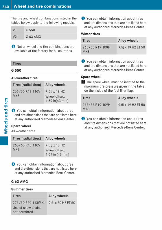
The tire and wheel combinations listed in thetables below apply to the following models:
V1 G 550
V2 G 63 AMG
i Not all wheel and tire combinations areavailable at the factory for all countries.
Tires
G 550
All-weather tires
Tires (radial tires) Alloy wheels
265/60 R18 110VM+S
7.5 J x 18 H2Wheel offset:1.69 in(43 mm)
i You can obtain information about tiresand tire dimensions that are not listed hereat any authorized Mercedes-Benz Center.
Spare wheelAll-weather tires
Tires (radial tires) Alloy wheels
265/60 R18 110VM+S
7.5 J x 18 H2Wheel offset:1.69 in (43 mm)
i You can obtain information about tiresand tire dimensions that are not listed hereat any authorized Mercedes-Benz Center.
G 63 AMG
Summer tires
Tires Alloy wheels
275/50 R20 113W XLUse of snow chainsnot permitted.
9.5J x 20 H2 ET 50
i You can obtain information about tiresand tire dimensions that are not listed hereat any authorized Mercedes-Benz Center.
Winter tires
Tires Alloy wheels
265/55 R19 109HM+S
9.5J x 19 H2 ET 50
i You can obtain information about tiresand tire dimensions that are not listed hereat any authorized Mercedes-Benz Center.
Spare wheel! The spare wheel must be inflated to themaximum tire pressure given in the tableon the inside of the fuel filler flap.
Tires Alloy wheels
265/55 R19 109HM+S
9.5J x 19 H2 ET 50
i You can obtain information about tiresand tire dimensions that are not listed hereat any authorized Mercedes-Benz Center.
340 Wheel and tire combinationsWheelsandtires

Useful information ............................ 342Identification plates ......................... 342Service products and filling capaci-ties ..................................................... 343Vehicle data ...................................... 350Vehicle data for off-road driving ..... 350Trailer tow hitch ................................ 351
341
Technicaldata
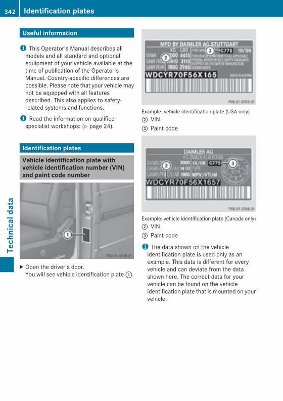
Useful information
i This Operator's Manual describes allmodels and all standard and optionalequipment of your vehicle available at thetime of publication of the Operator'sManual. Country-specific differences arepossible. Please note that your vehicle maynot be equipped with all featuresdescribed. This also applies to safety-related systems and functions.
i Read the information on qualifiedspecialist workshops: (Y page 24).
Identification plates
Vehicle identification plate withvehicle identification number (VIN)and paint code number
X Open the driver's door.You will see vehicle identification plate:.
Example: vehicle identification plate (USA only); VIN= Paint code
Example: vehicle identification plate (Canada only); VIN= Paint code
i The data shown on the vehicleidentification plate is used only as anexample. This data is different for everyvehicle and can deviate from the datashown here. The correct data for yourvehicle can be found on the vehicleidentification plate that is mounted on yourvehicle.
342 Identification platesTechnicaldata
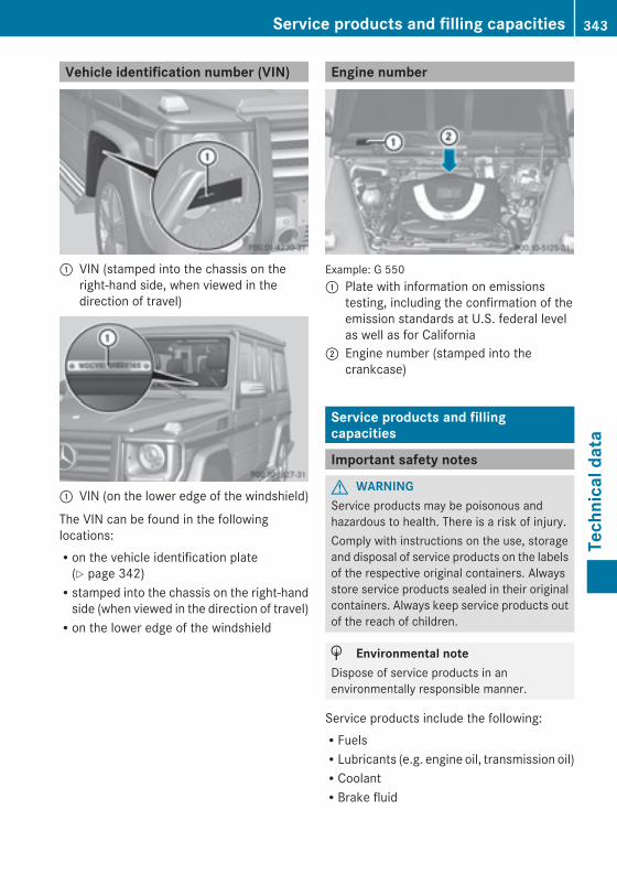
Vehicle identification number (VIN)
: VIN (stamped into the chassis on theright-hand side, when viewed in thedirection of travel)
: VIN (on the lower edge of the windshield)
The VIN can be found in the followinglocations:Ron the vehicle identification plate(Y page 342)Rstamped into the chassis on the right-handside (when viewed in the direction of travel)Ron the lower edge of the windshield
Engine number
Example: G 550: Plate with information on emissions
testing, including the confirmation of theemission standards at U.S. federal levelas well as for California
; Engine number (stamped into thecrankcase)
Service products and fillingcapacities
Important safety notes
G WARNINGService products may be poisonous andhazardous to health. There is a risk of injury.Comply with instructions on the use, storageand disposal of service products on the labelsof the respective original containers. Alwaysstore service products sealed in their originalcontainers. Always keep service products outof the reach of children.
H Environmental noteDispose of service products in anenvironmentally responsible manner.
Service products include the following:RFuelsRLubricants (e.g. engine oil, transmission oil)RCoolantRBrake fluid
Service products and filling capacities 343
Technicaldata
Z
RWindshield washer fluidRClimate control system refrigerantComponents and service products must bematched. You should therefore only useproducts that have been tested and approvedby Mercedes-Benz.Information on tested and approved productscan be obtained at an authorized Mercedes-Benz Center or on the Internet at http://bevo.mercedes-benz.com.You can recognize service products approvedby Mercedes-Benz by the followinginscription on the containers:RMB-Freigabe (e.g. MB-Freigabe 229.51)RMB Approval (e.g. MB Approval 229.51)Other designations or recommendationsindicate a level of quality or a specification inaccordance with an MB Sheet number (e.g.MB 229.5). They have not necessarily beenapproved by Mercedes-Benz.
Fuel
Important safety notes
G WARNINGFuel is highly flammable. If you handle fuelincorrectly, there is a risk of fire andexplosion.You must avoid fire, open flames, creatingsparks and smoking. Switch off the engineand, if applicable, the auxiliary heating beforerefueling.
G WARNINGFuel is poisonous and hazardous to health.There is a risk of injury.You must make sure that fuel does not comeinto contact with your skin, eyes or clothingand that it is not swallowed. Do not inhale fuelvapors. Keep fuel away from children.
If you or others come into contact with fuel,observe the following:RWash away fuel from skin immediatelyusing soap and water.RIf fuel comes into contact with your eyes,immediately rinse them thoroughly withclean water. Seek medical assistancewithout delay.RIf fuel is swallowed, seek medicalassistance without delay. Do not inducevomiting.RImmediately change out of clothing whichhas come into contact with fuel.
Tank capacity
Total capacity
All models 25.4 US gal(96.0 l)
Of which reserve
All models Approx.3.7 US gal(14.0 l)
Gasoline (EN 228)
Fuel grade! Do not use diesel to refuel vehicles with agasoline engine. Even small amounts of thewrong fuel result in damage to the fuelsystem and engine.
! You should only refuel with unleadedpremium-grade gasoline as this avoidsdamaging the catalytic converter.If engine running problems are apparent,have the cause checked immediately andrepaired. Excess unburned fuel canotherwise enter the catalytic converter,leading to overheating and possiblycausing a fire.
344 Service products and filling capacitiesTechnicaldata
! To ensure the longevity and fullperformance of the engine, only premium-grade unleaded gasoline may be used.If there is no premium-grade unleadedgasoline available and regular unleadedgasoline must be used, please observe thefollowing precautions:Ronly fill the fuel tank to half full withregular unleaded gasoline and fill the restwith premium-grade unleaded gasolineas soon as possible.Rdo not drive at the maximum speed.Ravoid sudden acceleration.Rif the vehicle is carrying a light load, e.g.two passengers without luggage, do notallow the engine to rev above 3000 rpm.Rif the vehicle is fully loaded or is beingoperated in mountainous terrain, do notdepress the accelerator pedal furtherthanÔ of the pedal travel.
! Use a filter when refueling from a fuel can.Otherwise, the fuel lines and/or injectionsystem could be blocked by particles fromthe fuel can.
Only refuel using premium-grade unleadedgasoline with a minimum octane rating of 91.Reformulated Gasoline (RFG) and/orunleaded gasolinewith additives can be used.The concentration of additives in the fuel,however, must not exceed 10%, e.g.:REthanolRTAMERETBERIPARTBAFor MTBE, the concentration should notexceed 15%.The concentration of methanol in gasoline,including other additives, must not exceed3%.Usingmixtures ofmethanol and ethanol is notpermitted. Gasohol, a mixture of 10% ethanoland 90% unleaded gasoline, may be used.
All of these mix fuels must fulfill the fuelrequirements, e.g.:Rknock resistanceRboiling pointRvapor pressureYouwill usually find information about the fuelgrade on the pump. If you cannot find thelabel on the pump, ask the staff forassistance.
i For further information, consult anauthorized Mercedes-Benz Center or onthe Internet at http://www.mbusa.com(USA only).
Information on refueling (Y page 153).
AMG vehicles! Only refuel using super-grade unleadedgasoline with at least 98 RON/88 MONthat conforms to European standardEN 228 or an equivalent specification.You could otherwise impair engine outputor damage the engine.
! Premium-grade unleaded gasoline withan octane rating of 95 RON/85 MON maybe used as a temporary measure if therecommended fuel is not available. Thismay reduce engine performance andincrease fuel consumption. Do not drive atfull throttle.
! Regular unleaded gasoline with an octanerating of 91 RON/82.5 MON may also beused as an emergency measure if therecommended fuel is not available.Doing so results in noticeably higher fuelconsumption, and the engine power outputis noticeably reduced. Avoid driving at fullthrottle.If only regular unleaded gasoline with anoctane rating of 91 RON/82.5 MON orlower is available, you must have thevehicle adapted to this fuel at a qualifiedspecialist workshop.
Service products and filling capacities 345
Technicaldata
Z
Additives! Do not refuel with low-grade fuel and donot use fuel additives that are not testedand approved for Mercedes-Benz vehicles.Damage to or malfunctions of the fuelsystem may otherwise occur.
One of the main problems of poor fuel qualityis the forming of deposits that are createdduring the gasoline combustion process.Mercedes-Benz recommends that you usebranded fuels that have additives.If you use fuels without these additives overa longer period of time, carbon deposits maybuild up. These deposits form at the inletvalves and in the combustion chamber inparticular.This could lead to engine problems, e.g.:Rlonger engine warm-up phaseRuneven idleRengine noiseRmisfiringRloss of powerCarbon deposits may form if the availabilityof gasoline with relevant additives isinsufficient (in certain regions). In this case,Mercedes-Benz recommends additivesapproved for use in Mercedes-Benz vehicles;see http://bevo.mercedes-benz.com.For a list of approved products, consult anauthorized Mercedes-Benz Center. Complywith the instructions for use on the productlabel.Do not mix other fuel additives with fuel. Thiscauses unnecessary costs and could damagethe engine.
Notes on fuel consumption
H Environmental noteCO2 (carbon dioxide) is the gas whichscientists believe to be principally responsiblefor global warming (the greenhouse effect).Your vehicle's CO2 emissions are directlyrelated to fuel consumption and thereforedepend on:
Refficient use of the fuel by the engineRdriving styleRother non-technical factors, such asenvironmental influences, road conditionsor traffic flow
You can minimize your vehicle's CO2
emissions by driving carefully and having itserviced regularly.
The vehicle will use more fuel than usual inthe following situations:Rat very low outside temperaturesRin city trafficRon short journeysRin mountainous terrainRwhen towing a trailer
Engine oil
General notes! Never use engine oil or an oil filter of aspecification other than is necessary tofulfill the prescribed service intervals. Donot change the engine oil or oil filter inorder to achieve longer replacementintervals than those prescribed. You couldotherwise cause engine damage or damageto the exhaust gas aftertreatment.Follow the instructions in the serviceinterval display regarding the oil change.Otherwise, youmay damage the engine andthe exhaust gas aftertreatment.
The engine oils are matched to theperformance of Mercedes-Benz engines andservice intervals. For this reason, only useengine oils and oil filters that are approved forvehicles with a service system.For a list of approved engine oils and oil filters,consult an authorized Mercedes-Benz Centeror go to the Internet sitehttp://bevo.mercedes-benz.com (USAonly).The table shows which engine oils have beenapproved for your vehicle.
346 Service products and filling capacitiesTechnicaldata
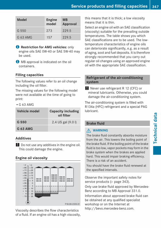
Model Enginemodel
MBApproval
G 550 273 229.5
G 63 AMG 157 229.5
i Restriction for AMG vehicles: onlyengine oils SAE 0W-40 or SAE 5W-40 maybe used.
i MB approval is indicated on the oilcontainers.
Filling capacitiesThe following values refer to an oil changeincluding the oil filter.The missing values for the following modelwere not available at the time of going toprint:RG 63 AMG
Vehicle model Capacity includingoil filter
G 550 2.4 US gal (9.0 l)
G 63 AMG
Additives! Do not use any additives in the engine oil.This could damage the engine.
Engine oil viscosity
Viscosity describes the flow characteristicsof a fluid. If an engine oil has a high viscosity,
this means that it is thick; a low viscositymeans that it is thin.Select an engine oil with an SAE classification(viscosity) suitable for the prevailing outsidetemperatures. The table shows you whichSAE classifications are to be used. The low-temperature characteristics of engine oilscan deteriorate significantly, e.g. as a resultof aging, soot and fuel deposits. It is thereforestrongly recommended that you carry outregular oil changes using an approved engineoil with the appropriate SAE classification.
Refrigerant of the air-conditioningsystem! Never use refrigerant R 12 (CFC) ormineral lubricants. Otherwise, you coulddamage the air-conditioning system.
The air-conditioning system is filled withR134a (HFC) refrigerant and a special PAGlubricant.
Brake fluid
G WARNINGThe brake fluid constantly absorbs moisturefrom the air. This lowers the boiling point ofthe brake fluid. If the boiling point of the brakefluid is too low, vapor pockets may form in thebrake system when the brakes are appliedhard. This would impair braking efficiency.There is a risk of an accident.You should have the brake fluid renewed atthe specified intervals.
Observe the important safety notes forservice products (Y page 343).Only use brake fluid approved by Mercedes-Benz according to MB Approval 331.0.Information about approved brake fluid canbe obtained at any qualified specialistworkshop or on the Internet athttp://bevo.mercedes-benz.com.
Service products and filling capacities 347
Technicaldata
Z
i Have the brake fluid regularly replaced ata qualified specialist workshop.
Coolant
Important safety notes
G WARNINGIf antifreeze comes into contact with hotcomponents in the engine compartment, itmay ignite. There is a risk of fire and injury.Let the engine cool down before you addantifreeze. Make sure that antifreeze is notspilled next to the filler neck. Thoroughlyclean the antifreeze from components beforestarting the engine.
! Only add coolant that has been premixedwith the desired antifreeze protection. Youcould otherwise damage the engine.Further information on coolants can befound in the Mercedes-Benz Specificationsfor Service Products, MB Specifications forService Products 310.1, e.g. on theInternet athttp://bevo.mercedes-benz.com. Orcontact a qualified specialist workshop.
! Always use a suitable coolant mixture,even in countries where high temperaturesprevail.Otherwise, the engine cooling system is notsufficiently protected from corrosion andoverheating.
The coolant is a mixture of water andantifreeze/corrosion inhibitor. It performsthe following tasks:Rcorrosion protectionRantifreeze protectionRraising the boiling pointIf the coolant has antifreeze protection downto -35 ‡ (-37 †), the boiling point of thecoolant in the pressurized system isapproximately 266 ‡ (130 †).
The antifreeze/corrosion inhibitorconcentration in the engine cooling systemshould:Rbe at least 50%. This will protect the enginecooling system against freezing down toapproximately -35 ‡ (-37 †).Rnot exceed 55% (antifreeze protectiondown to -49 ‡ [-45 †]). Otherwise, heatwill not be dissipated as effectively.
If the vehicle has lost coolant, add equalamounts of water and antifreeze/corrosioninhibitor. Mercedes-Benz recommends anantifreeze/corrosion inhibitor in accordancewith MB Specifications for Service Products310.1.The coolant is checked with everymaintenance interval at a qualified specialistworkshop.
i When the vehicle is first delivered, it isfilled with a coolant mixture that ensuresadequate antifreeze and corrosionprotection.
The engine cooling system is filled withcoolant at the factory which containsantifreeze/corrosion inhibitor that ensuresprotection down to approximately -35 ‡(-37 †).Your vehicle has a range of aluminumcomponents. Aluminum components in theengine make it necessary to use antifreeze/corrosion inhibitor that has been specificallyformulated to protect the aluminum parts.Failure to use such anticorrosion/antifreezecoolant will result in a significantly shortenedservice life.The coolantmust be used throughout the yearin order to maintain the necessary corrosionprotection and to provide protection fromoverheating. In the Maintenance Booklet, youcan find information on the intervals forrenewal.The renewal interval is determined by thecoolant type and the engine cooling systemdesign. The renewal interval in theMaintenance Booklet is only valid if the
348 Service products and filling capacitiesTechnicaldata
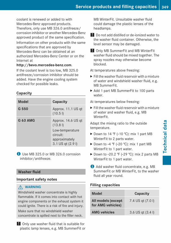
coolant is renewed or added to withMercedes-Benz approved products.Therefore, only use MB 326.0 antifreeze/corrosion inhibitor or anotherMercedes-Benzapproved product of the same specification.Information on other products with the samespecifications that are approved byMercedes-Benz can be obtained at anauthorized Mercedes-Benz Center or on theInternet athttp://bevo.mercedes-benz.com.If the coolant level is too low, MB 325.0antifreeze/corrosion inhibitor should beadded. Have the engine cooling systemchecked for possible leaks.
Capacity
Model Capacity
G 550 Approx. 11.1 US qt(10.5 l)
G 63 AMG Approx. 14.6 US qt(13.8 l)Low-temperaturecircuit:approximately3.1 US qt (2.9 l)
i Use MB 325.0 or MB 326.0 corrosioninhibitor/antifreeze.
Washer fluid
Important safety notes
G WARNINGWindshield washer concentrate is highlyflammable. If it comes into contact with hotengine components or the exhaust system itcould ignite. There is a risk of fire and injury.Make sure that no windshield washerconcentrate is spilled next to the filler neck.
! Only use washer fluid that is suitable forplastic lamp lenses, e.g. MB SummerFit or
MB WinterFit. Unsuitable washer fluidcould damage the plastic lenses of theheadlamps.
! Do not add distilled or de-ionized water tothe washer fluid container. Otherwise, thelevel sensor may be damaged.
! Only MB SummerFit and MB WinterFitwasher fluid should be mixed together. Thespray nozzles may otherwise becomeblocked.
At temperatures above freezing:X Fill the washer fluid reservoir with amixtureof water and windshield washer fluid, e.g.MB SummerFit.
X Add 1 part MB SummerFit to 100 partswater.
At temperatures below freezing:X Fill the washer fluid reservoir with amixtureof water and washer fluid, e.g. MBWinterFit.
Adapt the mixing ratio to the outsidetemperature.X Down to 14 ‡ (Ò10 †): mix 1 part MBWinterFit to 2 parts water.
X Down to Ò4 ‡ (Ò20 †): mix 1 part MBWinterFit to 1 part water.
X Down to Ò20.2 ‡ (Ò29 †): mix 2 parts MBWinterFit to 1 part water.
i Add washer fluid concentrate, e.g. MBSummerFit or MB WinterFit, to the washerfluid all year round.
Filling capacities
Model Capacity
All models (exceptfor AMG vehicles)
7.4 US qt (7.0 l)
AMG vehicles 3.6 US qt (3.4 l)
Service products and filling capacities 349
Technicaldata
Z
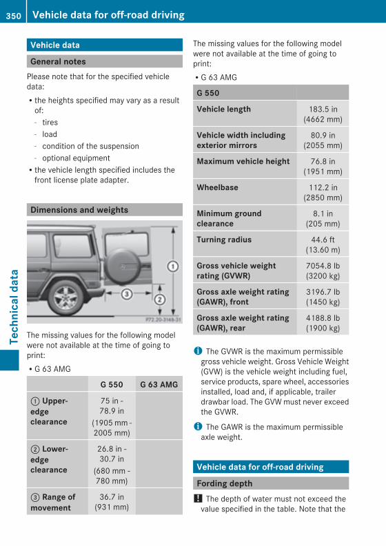
Vehicle data
General notesPlease note that for the specified vehicledata:Rthe heights specified may vary as a resultof:- tires- load- condition of the suspension- optional equipmentRthe vehicle length specified includes thefront license plate adapter.
Dimensions and weights
The missing values for the following modelwere not available at the time of going toprint:RG 63 AMG
G 550 G 63 AMG
: Upper-edgeclearance
75 in -78.9 in
(1905mm -2005 mm)
; Lower-edgeclearance
26.8 in -30.7 in
(680 mm -780 mm)
= Range ofmovement
36.7 in(931 mm)
The missing values for the following modelwere not available at the time of going toprint:RG 63 AMG
G 550
Vehicle length 183.5 in(4662 mm)
Vehicle width includingexterior mirrors
80.9 in(2055 mm)
Maximum vehicle height 76.8 in(1951 mm)
Wheelbase 112.2 in(2850 mm)
Minimum groundclearance
8.1 in(205 mm)
Turning radius 44.6 ft(13.60 m)
Gross vehicle weightrating (GVWR)
7054.8 lb(3200 kg)
Gross axle weight rating(GAWR), front
3196.7 lb(1450 kg)
Gross axle weight rating(GAWR), rear
4188.8 lb(1900 kg)
i The GVWR is the maximum permissiblegross vehicle weight. Gross Vehicle Weight(GVW) is the vehicle weight including fuel,service products, spare wheel, accessoriesinstalled, load and, if applicable, trailerdrawbar load. The GVWmust never exceedthe GVWR.
i The GAWR is the maximum permissibleaxle weight.
Vehicle data for off-road driving
Fording depth! The depth of water must not exceed thevalue specified in the table. Note that the
350 Vehicle data for off-road drivingTechnicaldata
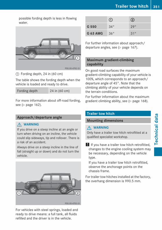
possible fording depth is less in flowingwater.
: Fording depth, 24 in (60 cm)
The table shows the fording depth when thevehicle is loaded and ready to drive.
Fording depth 24 in (60 cm)
For more information about off-road fording,see (Y page 162).
Approach/departure angle
G WARNINGIf you drive on a steep incline at an angle orturn when driving on an incline, the vehiclecould slip sideways, tip and rollover. There isa risk of an accident.Always drive on a steep incline in the line offall (straight up or down) and do not turn thevehicle.
For vehicles with steel springs, loaded andready to drive means: a full tank, all fluidsrefilled and the driver is in the vehicle.
:: ;;
G 550 34° 29°
G 63 AMG 36° 31°
For further information about approach/departure angles, see (Y page 167).
Maximum gradient-climbingcapabilityOn good road surfaces the maximumgradient-climbing capability of your vehicle is100%, which corresponds to an approach/departure angle of 45°. Note that theclimbing ability of your vehicle depends onthe terrain conditions.For further information about the maximumgradient climbing ability, see (Y page 168).
Trailer tow hitch
Mounting dimensions
G WARNINGOnly have a trailer tow hitch retrofitted at aqualified specialist workshop.
! If you have a trailer tow hitch retrofitted,changes to the engine cooling system maybe necessary, depending on the vehicletype.If you have a trailer tow hitch retrofitted,observe the anchorage points on thechassis frame.
For trailer tow hitches installed at the factory,the overhang dimension is 990.5 mm.
Trailer tow hitch 351
Technicaldata
Z
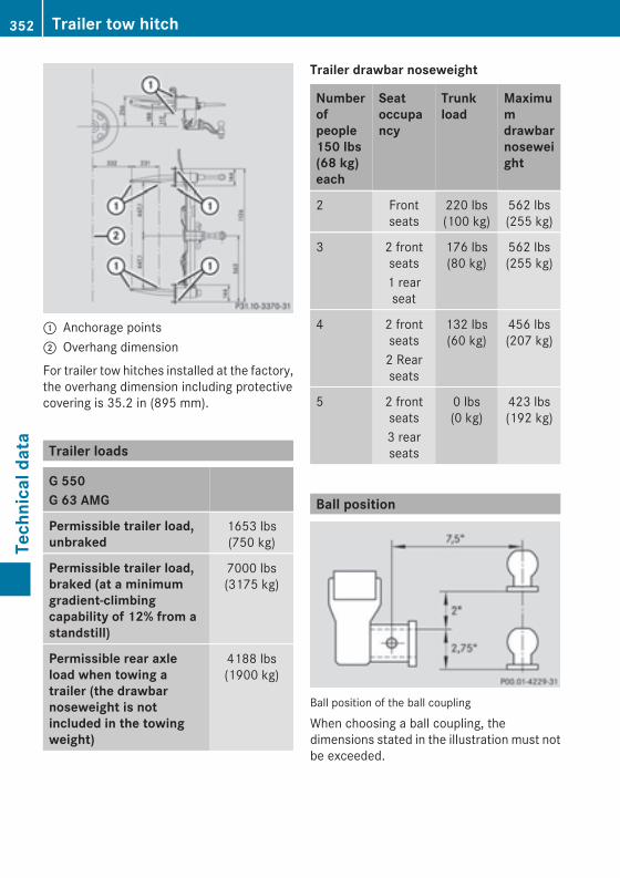
: Anchorage points; Overhang dimension
For trailer tow hitches installed at the factory,the overhang dimension including protectivecovering is 35.2 in (895 mm).
Trailer loads
G 550G 63 AMG
Permissible trailer load,unbraked
1653 lbs(750 kg)
Permissible trailer load,braked (at a minimumgradient-climbingcapability of 12% from astandstill)
7000 lbs(3175 kg)
Permissible rear axleload when towing atrailer (the drawbarnoseweight is notincluded in the towingweight)
4188 lbs(1900 kg)
Trailer drawbar noseweight
Numberofpeople150 lbs(68 kg)each
Seatoccupancy
Trunkload
Maximumdrawbarnoseweight
2 Frontseats
220 lbs(100 kg)
562 lbs(255 kg)
3 2 frontseats1 rearseat
176 lbs(80 kg)
562 lbs(255 kg)
4 2 frontseats2 Rearseats
132 lbs(60 kg)
456 lbs(207 kg)
5 2 frontseats3 rearseats
0 lbs(0 kg)
423 lbs(192 kg)
Ball position
Ball position of the ball coupling
When choosing a ball coupling, thedimensions stated in the illustration must notbe exceeded.
352 Trailer tow hitchTechnicaldata