avalon interface specifications · avalon memory mapped interface (avalon-mm)—an address-based...
TRANSCRIPT

101 Innovation DriveSan Jose, CA 95134www.altera.com
Avalon Interface Specifications
Document Version: 1.3Document Date: © August 2010

Copyright © 2009 Altera Corporation. All rights reserved. Altera, The Programmable Solutions Company, the stylized Altera logo, specific device designations, and all otherwords and logos that are identified as trademarks and/or service marks are, unless noted otherwise, the trademarks and service marks of Altera Corporation in the U.S. and othercountries. All other product or service names are the property of their respective holders. Altera products are protected under numerous U.S. and foreign patents and pending ap-plications, maskwork rights, and copyrights. Altera warrants performance of its semiconductor products to current specifications in accordance with Altera's standard warranty,but reserves the right to make changes to any products and services at any time without notice. Altera assumes no responsibility or liability arising out of the application or use ofany information, product, or service described herein except as expressly agreed to in writing by Altera Corporation. Altera customers are advised to obtain the latest version ofdevice specifications before relying on any published information and before placing orders for products or services.
MNL-AVABUSREF-1.3
© August 2010 Altera Corporation
Contents
Chapter 1. Introduction1.1. Avalon Properties and Parameters . . . . . . . . . . . . . . . . . . . . . . . . . . . . . . . . . . . . . . . . . . . . . . . . . . . . 1-41.2. Signal Types . . . . . . . . . . . . . . . . . . . . . . . . . . . . . . . . . . . . . . . . . . . . . . . . . . . . . . . . . . . . . . . . . . . . . . . 1-41.3. Interface Timing . . . . . . . . . . . . . . . . . . . . . . . . . . . . . . . . . . . . . . . . . . . . . . . . . . . . . . . . . . . . . . . . . . . . 1-41.4. Related Documents . . . . . . . . . . . . . . . . . . . . . . . . . . . . . . . . . . . . . . . . . . . . . . . . . . . . . . . . . . . . . . . . . 1-4
Chapter 2. Clock Interfaces2.1. Clock Input (Sink) . . . . . . . . . . . . . . . . . . . . . . . . . . . . . . . . . . . . . . . . . . . . . . . . . . . . . . . . . . . . . . . . . . 2-1
2.1.1. Properties . . . . . . . . . . . . . . . . . . . . . . . . . . . . . . . . . . . . . . . . . . . . . . . . . . . . . . . . . . . . . . . . . . . . . 2-12.1.2. Signal Types . . . . . . . . . . . . . . . . . . . . . . . . . . . . . . . . . . . . . . . . . . . . . . . . . . . . . . . . . . . . . . . . . . . 2-12.1.3. associatedClock Interfaces . . . . . . . . . . . . . . . . . . . . . . . . . . . . . . . . . . . . . . . . . . . . . . . . . . . . . . . 2-2
2.2. Clock Output (Source) . . . . . . . . . . . . . . . . . . . . . . . . . . . . . . . . . . . . . . . . . . . . . . . . . . . . . . . . . . . . . . 2-22.2.1. Properties . . . . . . . . . . . . . . . . . . . . . . . . . . . . . . . . . . . . . . . . . . . . . . . . . . . . . . . . . . . . . . . . . . . . . 2-22.2.2. Signal Types . . . . . . . . . . . . . . . . . . . . . . . . . . . . . . . . . . . . . . . . . . . . . . . . . . . . . . . . . . . . . . . . . . . 2-2
Chapter 3. Avalon Memory-Mapped Interfaces3.1. Introduction . . . . . . . . . . . . . . . . . . . . . . . . . . . . . . . . . . . . . . . . . . . . . . . . . . . . . . . . . . . . . . . . . . . . . . . . 3-13.2. Slaves . . . . . . . . . . . . . . . . . . . . . . . . . . . . . . . . . . . . . . . . . . . . . . . . . . . . . . . . . . . . . . . . . . . . . . . . . . . . . 3-23.3. Slave Interface Properties . . . . . . . . . . . . . . . . . . . . . . . . . . . . . . . . . . . . . . . . . . . . . . . . . . . . . . . . . . . . 3-53.4. Slave Timing . . . . . . . . . . . . . . . . . . . . . . . . . . . . . . . . . . . . . . . . . . . . . . . . . . . . . . . . . . . . . . . . . . . . . . . 3-6
3.4.1. Synchronous Interface . . . . . . . . . . . . . . . . . . . . . . . . . . . . . . . . . . . . . . . . . . . . . . . . . . . . . . . . . . 3-63.4.2. Performance . . . . . . . . . . . . . . . . . . . . . . . . . . . . . . . . . . . . . . . . . . . . . . . . . . . . . . . . . . . . . . . . . . . 3-63.4.3. Electrical Characteristics . . . . . . . . . . . . . . . . . . . . . . . . . . . . . . . . . . . . . . . . . . . . . . . . . . . . . . . . . 3-7
3.5. Slave Transfers . . . . . . . . . . . . . . . . . . . . . . . . . . . . . . . . . . . . . . . . . . . . . . . . . . . . . . . . . . . . . . . . . . . . . 3-73.5.1. Typical Slave Read and Write Transfers . . . . . . . . . . . . . . . . . . . . . . . . . . . . . . . . . . . . . . . . . . . 3-73.5.2. Slave Read and Write Transfers with Fixed Wait-States . . . . . . . . . . . . . . . . . . . . . . . . . . . . . . 3-83.5.3. Pipelined Transfers . . . . . . . . . . . . . . . . . . . . . . . . . . . . . . . . . . . . . . . . . . . . . . . . . . . . . . . . . . . . . 3-9
3.5.3.1. Slave Pipelined Read Transfer with Variable Latency . . . . . . . . . . . . . . . . . . . . . . . . . . 3-103.5.3.2. Slave Pipelined Read Transfer with Fixed Latency . . . . . . . . . . . . . . . . . . . . . . . . . . . . . 3-11
3.5.4. Burst Transfer . . . . . . . . . . . . . . . . . . . . . . . . . . . . . . . . . . . . . . . . . . . . . . . . . . . . . . . . . . . . . . . . . 3-113.5.4.1. Slave Write Bursts . . . . . . . . . . . . . . . . . . . . . . . . . . . . . . . . . . . . . . . . . . . . . . . . . . . . . . . . . 3-123.5.4.2. Slave Read Bursts . . . . . . . . . . . . . . . . . . . . . . . . . . . . . . . . . . . . . . . . . . . . . . . . . . . . . . . . . 3-133.5.4.3. Line–Wrapped Bursts . . . . . . . . . . . . . . . . . . . . . . . . . . . . . . . . . . . . . . . . . . . . . . . . . . . . . . 3-143.5.4.4. Flow Control . . . . . . . . . . . . . . . . . . . . . . . . . . . . . . . . . . . . . . . . . . . . . . . . . . . . . . . . . . . . . 3-14
3.6. Address Alignment . . . . . . . . . . . . . . . . . . . . . . . . . . . . . . . . . . . . . . . . . . . . . . . . . . . . . . . . . . . . . . . . 3-153.6.1. Avalon-MM Slave Addressing . . . . . . . . . . . . . . . . . . . . . . . . . . . . . . . . . . . . . . . . . . . . . . . . . . 3-153.6.2. Avalon-MM Tri-State Slave Addressing . . . . . . . . . . . . . . . . . . . . . . . . . . . . . . . . . . . . . . . . . . 3-163.6.3. Native Addressing . . . . . . . . . . . . . . . . . . . . . . . . . . . . . . . . . . . . . . . . . . . . . . . . . . . . . . . . . . . . . 3-17
3.7. Masters . . . . . . . . . . . . . . . . . . . . . . . . . . . . . . . . . . . . . . . . . . . . . . . . . . . . . . . . . . . . . . . . . . . . . . . . . . . 3-173.8. Master Signal Types . . . . . . . . . . . . . . . . . . . . . . . . . . . . . . . . . . . . . . . . . . . . . . . . . . . . . . . . . . . . . . . . 3-183.9. Master Interface Properties . . . . . . . . . . . . . . . . . . . . . . . . . . . . . . . . . . . . . . . . . . . . . . . . . . . . . . . . . . 3-213.10. Master Transfers . . . . . . . . . . . . . . . . . . . . . . . . . . . . . . . . . . . . . . . . . . . . . . . . . . . . . . . . . . . . . . . . . . 3-21
3.10.1. Master Pipelined Read Transfer . . . . . . . . . . . . . . . . . . . . . . . . . . . . . . . . . . . . . . . . . . . . . . . . 3-223.10.2. Burst Transfers . . . . . . . . . . . . . . . . . . . . . . . . . . . . . . . . . . . . . . . . . . . . . . . . . . . . . . . . . . . . . . . 3-23
3.10.2.1. Master Write Bursts . . . . . . . . . . . . . . . . . . . . . . . . . . . . . . . . . . . . . . . . . . . . . . . . . . . . . . 3-243.10.2.2. Master Read Bursts . . . . . . . . . . . . . . . . . . . . . . . . . . . . . . . . . . . . . . . . . . . . . . . . . . . . . . . 3-25
Avalon Interface Specifications
4
Chapter 4. Interrupt Interfaces4.1. Interrupt Sender . . . . . . . . . . . . . . . . . . . . . . . . . . . . . . . . . . . . . . . . . . . . . . . . . . . . . . . . . . . . . . . . . . . . 4-1
4.1.1. Signal Types . . . . . . . . . . . . . . . . . . . . . . . . . . . . . . . . . . . . . . . . . . . . . . . . . . . . . . . . . . . . . . . . . . . 4-14.1.2. Interrupt Sender Properties . . . . . . . . . . . . . . . . . . . . . . . . . . . . . . . . . . . . . . . . . . . . . . . . . . . . . . 4-1
4.2. Interrupt Receiver . . . . . . . . . . . . . . . . . . . . . . . . . . . . . . . . . . . . . . . . . . . . . . . . . . . . . . . . . . . . . . . . . . . 4-14.2.1. Interrupt Receiver Properties . . . . . . . . . . . . . . . . . . . . . . . . . . . . . . . . . . . . . . . . . . . . . . . . . . . . . 4-24.2.2. Signal Types . . . . . . . . . . . . . . . . . . . . . . . . . . . . . . . . . . . . . . . . . . . . . . . . . . . . . . . . . . . . . . . . . . . 4-24.2.3. Interrupt Timing . . . . . . . . . . . . . . . . . . . . . . . . . . . . . . . . . . . . . . . . . . . . . . . . . . . . . . . . . . . . . . . 4-2
Chapter 5. Avalon Memory-Mapped Tri-state Interfaces5.1. Tri-state Slave Signal Types . . . . . . . . . . . . . . . . . . . . . . . . . . . . . . . . . . . . . . . . . . . . . . . . . . . . . . . . . . 5-1
5.1.1. address Behavior . . . . . . . . . . . . . . . . . . . . . . . . . . . . . . . . . . . . . . . . . . . . . . . . . . . . . . . . . . . . . . . 5-35.1.2. outputenable and read Behavior . . . . . . . . . . . . . . . . . . . . . . . . . . . . . . . . . . . . . . . . . . . . . . . . . . 5-35.1.3. write_n and writebyteenable Behavior . . . . . . . . . . . . . . . . . . . . . . . . . . . . . . . . . . . . . . . . . . . . 5-35.1.4. Interfacing to Synchronous Off-Chip Memory . . . . . . . . . . . . . . . . . . . . . . . . . . . . . . . . . . . . . . 5-3
5.2. tri-state Slave Properties . . . . . . . . . . . . . . . . . . . . . . . . . . . . . . . . . . . . . . . . . . . . . . . . . . . . . . . . . . . . . 5-45.3. Slave Transfers . . . . . . . . . . . . . . . . . . . . . . . . . . . . . . . . . . . . . . . . . . . . . . . . . . . . . . . . . . . . . . . . . . . . . 5-5
5.3.1. Asynchronous Transfers . . . . . . . . . . . . . . . . . . . . . . . . . . . . . . . . . . . . . . . . . . . . . . . . . . . . . . . . . 5-55.3.1.1. Setup Time . . . . . . . . . . . . . . . . . . . . . . . . . . . . . . . . . . . . . . . . . . . . . . . . . . . . . . . . . . . . . . . . 5-65.3.1.2. Hold Time . . . . . . . . . . . . . . . . . . . . . . . . . . . . . . . . . . . . . . . . . . . . . . . . . . . . . . . . . . . . . . . . 5-65.3.1.3. Example Read and Write Using Setup, Hold and Wait Times . . . . . . . . . . . . . . . . . . . . 5-6
5.3.2. Synchronous Transfers . . . . . . . . . . . . . . . . . . . . . . . . . . . . . . . . . . . . . . . . . . . . . . . . . . . . . . . . . . 5-85.3.3. Pipelined Slave Read Transfers . . . . . . . . . . . . . . . . . . . . . . . . . . . . . . . . . . . . . . . . . . . . . . . . . . . 5-8
5.4. Master Transfers . . . . . . . . . . . . . . . . . . . . . . . . . . . . . . . . . . . . . . . . . . . . . . . . . . . . . . . . . . . . . . . . . . . 5-10
Chapter 6. Avalon Streaming Interfaces6.1. Introduction . . . . . . . . . . . . . . . . . . . . . . . . . . . . . . . . . . . . . . . . . . . . . . . . . . . . . . . . . . . . . . . . . . . . . . . . 6-1
6.1.1. Features . . . . . . . . . . . . . . . . . . . . . . . . . . . . . . . . . . . . . . . . . . . . . . . . . . . . . . . . . . . . . . . . . . . . . . . 6-26.1.2. Terms and Concepts . . . . . . . . . . . . . . . . . . . . . . . . . . . . . . . . . . . . . . . . . . . . . . . . . . . . . . . . . . . . 6-2
6.2. Avalon-ST Interface Signals . . . . . . . . . . . . . . . . . . . . . . . . . . . . . . . . . . . . . . . . . . . . . . . . . . . . . . . . . . 6-36.2.1. Signal Polarity . . . . . . . . . . . . . . . . . . . . . . . . . . . . . . . . . . . . . . . . . . . . . . . . . . . . . . . . . . . . . . . . . 6-46.2.2. Signal Sequencing and Timing . . . . . . . . . . . . . . . . . . . . . . . . . . . . . . . . . . . . . . . . . . . . . . . . . . . 6-4
6.2.2.1. Synchronous Interface . . . . . . . . . . . . . . . . . . . . . . . . . . . . . . . . . . . . . . . . . . . . . . . . . . . . . . 6-46.2.2.2. Clock Enables . . . . . . . . . . . . . . . . . . . . . . . . . . . . . . . . . . . . . . . . . . . . . . . . . . . . . . . . . . . . . 6-4
6.3. Avalon-ST Interface Properties . . . . . . . . . . . . . . . . . . . . . . . . . . . . . . . . . . . . . . . . . . . . . . . . . . . . . . . 6-46.4. Typical Data Transfers . . . . . . . . . . . . . . . . . . . . . . . . . . . . . . . . . . . . . . . . . . . . . . . . . . . . . . . . . . . . . . . 6-4
6.4.1. Signal Details . . . . . . . . . . . . . . . . . . . . . . . . . . . . . . . . . . . . . . . . . . . . . . . . . . . . . . . . . . . . . . . . . . 6-56.4.2. Data Layout . . . . . . . . . . . . . . . . . . . . . . . . . . . . . . . . . . . . . . . . . . . . . . . . . . . . . . . . . . . . . . . . . . . 6-6
6.5. Data Transfer without Backpressure . . . . . . . . . . . . . . . . . . . . . . . . . . . . . . . . . . . . . . . . . . . . . . . . . . . 6-66.6. Data Transfer with Backpressure . . . . . . . . . . . . . . . . . . . . . . . . . . . . . . . . . . . . . . . . . . . . . . . . . . . . . . 6-76.7. Packet Data Transfers . . . . . . . . . . . . . . . . . . . . . . . . . . . . . . . . . . . . . . . . . . . . . . . . . . . . . . . . . . . . . . . 6-9
6.7.1. Signal Details . . . . . . . . . . . . . . . . . . . . . . . . . . . . . . . . . . . . . . . . . . . . . . . . . . . . . . . . . . . . . . . . . . 6-96.7.2. Protocol Details . . . . . . . . . . . . . . . . . . . . . . . . . . . . . . . . . . . . . . . . . . . . . . . . . . . . . . . . . . . . . . . 6-10
Chapter 7. Conduit Interfaces7.1. Properties . . . . . . . . . . . . . . . . . . . . . . . . . . . . . . . . . . . . . . . . . . . . . . . . . . . . . . . . . . . . . . . . . . . . . . . . . . 7-17.2. Signals . . . . . . . . . . . . . . . . . . . . . . . . . . . . . . . . . . . . . . . . . . . . . . . . . . . . . . . . . . . . . . . . . . . . . . . . . . . . 7-2
Additional InformationDocument Revision History . . . . . . . . . . . . . . . . . . . . . . . . . . . . . . . . . . . . . . . . . . . . . . . . . . . . . . . . . . . . Info-1How to Contact Altera . . . . . . . . . . . . . . . . . . . . . . . . . . . . . . . . . . . . . . . . . . . . . . . . . . . . . . . . . . . . . . . . . Info-1Typographic Conventions . . . . . . . . . . . . . . . . . . . . . . . . . . . . . . . . . . . . . . . . . . . . . . . . . . . . . . . . . . . . . . Info-2
Avalon Interface Specifications © August 2010 Altera Corporation
© August 2010 Altera Corporation
1. Introduction
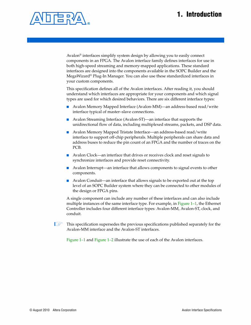
Avalon® interfaces simplify system design by allowing you to easily connect components in an FPGA. The Avalon interface family defines interfaces for use in both high-speed streaming and memory-mapped applications. These standard interfaces are designed into the components available in the SOPC Builder and the MegaWizard® Plug-In Manager. You can also use these standardized interfaces in your custom components.
This specification defines all of the Avalon interfaces. After reading it, you should understand which interfaces are appropriate for your components and which signal types are used for which desired behaviors. There are six different interface types:
■ Avalon Memory Mapped Interface (Avalon-MM)—an address-based read/write interface typical of master–slave connections.
■ Avalon Streaming Interface (Avalon-ST)—an interface that supports the unidirectional flow of data, including multiplexed streams, packets, and DSP data.
■ Avalon Memory Mapped Tristate Interface—an address-based read/write interface to support off-chip peripherals. Multiple peripherals can share data and address buses to reduce the pin count of an FPGA and the number of traces on the PCB.
■ Avalon Clock—an interface that drives or receives clock and reset signals to synchronize interfaces and provide reset connectivity.
■ Avalon Interrupt—an interface that allows components to signal events to other components.
■ Avalon Conduit—an interface that allows signals to be exported out at the top level of an SOPC Builder system where they can be connected to other modules of the design or FPGA pins.
A single component can include any number of these interfaces and can also include multiple instances of the same interface type. For example, in Figure 1–1, the Ethernet Controller includes four different interface types: Avalon-MM, Avalon-ST, clock, and conduit.
1 This specification supersedes the previous specifications published separately for the Avalon-MM interface and the Avalon-ST interfaces.
Figure 1–1 and Figure 1–2 illustrate the use of each of the Avalon interfaces.
Avalon Interface Specifications
1–2 Chapter 1: Introduction
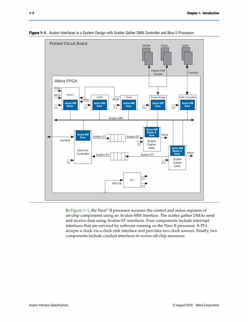
In Figure 1–1, the Nios® II processor accesses the control and status registers of on-chip components using an Avalon-MM interface. The scatter gather DMAs send and receive data using Avalon-ST interfaces. Four components include interrupt interfaces that are serviced by software running on the Nios II processor. A PLL accepts a clock via a clock sink interface and provides two clock sources. Finally, two components include conduit interfaces to access off-chip resources.
Figure 1–1. Avalon Interfaces in a System Design with Scatter Gather DMA Controller and Nios II Processor
IRQ1 IRQ2
C1 C1
Conduit
Avalon-MM
C2
Avalon-ST
C1C1
Avalon-ST
Avalon-ST Avalon-ST
C2
C2C2
C1
C2Ref Clk
FlashSRAM DDR
Avalon-MMTristate Conduit
Altera FPGA
Printed Circuit Board
IRQ3
IRQ4
IRQ3
IRQ4
Avalon-MMMaster
Avalon-MMSlave
Avalon-MMMaster &
Slave
Avalon-MMMaster &
Slave
Avalon-MMSlave
Timer
Avalon-MMSlave
UARTNios II
Avalon-MMSlave
Tristate Bridge
PLL
Avalon-MMSlave
DDR Controller
EthernetController
ScatterGatherDMA
ScatterGatherDMA
Avalon Interface Specifications © August 2010 Altera Corporation
Chapter 1: Introduction 1–3
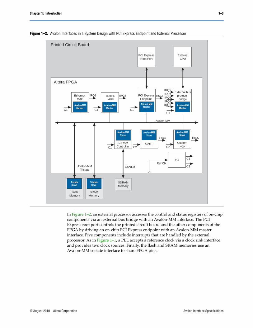
In Figure 1–2, an external processor accesses the control and status registers of on-chip components via an external bus bridge with an Avalon-MM interface. The PCI Express root port controls the printed circuit board and the other components of the FPGA by driving an on-chip PCI Express endpoint with an Avalon-MM master interface. Five components include interrupts that are handled by the external processor. As in Figure 1–1, a PLL accepts a reference clock via a clock sink interface and provides two clock sources. Finally, the flash and SRAM memories use an Avalon-MM tristate interface to share FPGA pins.
Figure 1–2. Avalon Interfaces in a System Design with PCI Express Endpoint and External Processor
ConduitAvalon-MMTristate
Avalon-MM
C1
C1
C2Ref Clk
Altera FPGA
Printed Circuit Board
Avalon-MMSlave
PLL
SDRAMController C2
IRQ4
Avalon-MM Slave
UARTC2
IRQ5
Avalon-MM Slave
CustomLogic
C1C1
Avalon-MMMaster
Avalon-MMMaster
Ethernet MAC
Custom Logic
TristateSlave
TristateSlave
C1C1
IRQ2IRQ1
IRQ3IRQ4IRQ5
IRQ1 IRQ2 IRQ3
ExternalCPU
PCI ExpressRoot Port
Avalon-MMMaster
External busprotocol bridge
Avalon-MMMaster
PCI ExpressEndpoint
Flash Memory
SRAMMemory
SDRAMMemory
© August 2010 Altera Corporation Avalon Interface Specifications
1–4 Chapter 1: IntroductionAvalon Properties and Parameters
1.1. Avalon Properties and ParametersAvalon interfaces use properties to describe their behavior. For example, the setupTime and holdTime properties of an Avalon-MM tristate interface specify the timing of external memory devices. The maxChannel property of Avalon-ST interfaces allows you to state the number of channels supported by the interface. The specification for each interface type defines all of its properties and specifies the default values. For a complete list of properties for each interface type, refer to the following sections:
■ For Avalon-MM properties, refer to: “Slave Interface Properties” on page 3–5 and “Master Interface Properties” on page 3–22
■ For Avalon-MM tristate properties, refer to: “tri-state Slave Properties” on page 5–4
■ For Avalon-ST properties, refer to: “Avalon-ST Interface Properties” on page 6–4
■ For the properties of interrupts, refer to: “Interrupt Sender Properties” on page 4–1 and “Interrupt Receiver Properties” on page 4–2
1.2. Signal TypesEach of the Avalon interfaces defines a number of signal types and their behavior. Many signal types are optional, allowing component designers the flexibility to select only the signal types necessary. For example, the Avalon-MM interface includes optional beginbursttransfer and burstcount signal types used only for components that support bursting. The Avalon-ST interface includes the optional startofpacket and endofpacket signal types for interfaces that support packets.
With the exception of conduit interfaces, each interface may only include one signal of each signal type. Active-low signals are permitted for many signal types. Active-high signals are generally used in this document.
1.3. Interface TimingSubsequent chapters of this document include timing information that describes transfers for individual interface types interfaces. There is no guaranteed performance for any of these interfaces; actual performance depends on many factors, including component design and system implementation.
Most Avalon interfaces must not be edge sensitive to signals other than the clock, because the signals may transition multiple times before they stabilize. The exact timing of signals between clock edges varies depending upon the characteristics of the selected Altera device.
1.4. Related DocumentsYou can find additional information on related topics in the following documents:
■ Quartus II Handbook Volume 4: SOPC Builder
This volume includes information on memory-mapped and streaming interfaces, Tcl scripting, designing memory sub-systems, and interconnect components.
Avalon Interface Specifications © August 2010 Altera Corporation

Chapter 1: Introduction 1–5Related Documents
■ Quartus II Handbook Volume 5: Embedded Peripherals
This volume includes documentation for the many embedded peripherals that are available in SOPC Builder.
■ Building a Component Interface with Tcl Scripting Commands.
This is a reference for a programmatic interface that you can use to define SOPC Builder components.
You can also complete a one-hour online course, Using SOPC Builder, that is available on the Altera web site.
© August 2010 Altera Corporation Avalon Interface Specifications

1–6 Chapter 1: IntroductionRelated Documents
Avalon Interface Specifications © August 2010 Altera Corporation
© August 2010 Altera Corporation
2. Clock Interfaces
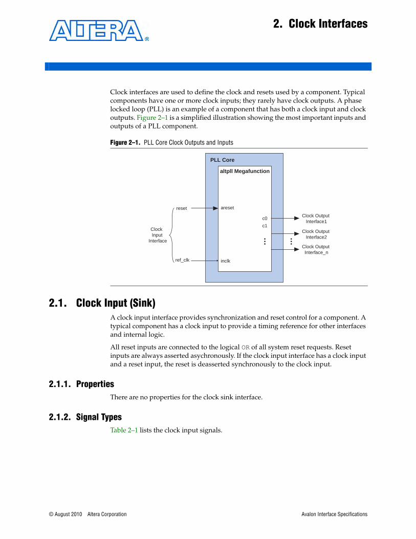
Clock interfaces are used to define the clock and resets used by a component. Typical components have one or more clock inputs; they rarely have clock outputs. A phase locked loop (PLL) is an example of a component that has both a clock input and clock outputs. Figure 2–1 is a simplified illustration showing the most important inputs and outputs of a PLL component.
2.1. Clock Input (Sink)A clock input interface provides synchronization and reset control for a component. A typical component has a clock input to provide a timing reference for other interfaces and internal logic.
All reset inputs are connected to the logical OR of all system reset requests. Reset inputs are always asserted asychronously. If the clock input interface has a clock input and a reset input, the reset is deasserted synchronously to the clock input.
2.1.1. PropertiesThere are no properties for the clock sink interface.
2.1.2. Signal TypesTable 2–1 lists the clock input signals.
Figure 2–1. PLL Core Clock Outputs and Inputs
PLL Core
altpll Megafunction
ref_clk inclk
Clock Output Interface1
Clock Input
Interface
Clock Output Interface2
Clock Output Interface_n
c0
c1
aresetreset
Avalon Interface Specifications
2–2 Chapter 2: Clock InterfacesClock Output (Source)
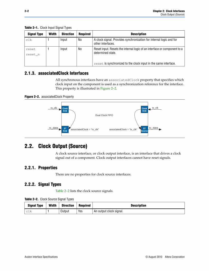
2.1.3. associatedClock Interfaces All synchronous interfaces have an associatedClock property that specifies which clock input on the component is used as a synchronization reference for the interface. This property is illustrated in Figure 2–2.
2.2. Clock Output (Source)A clock source interface, or clock output interface, is an interface that drives a clock signal out of a component. Clock output interfaces cannot have reset signals.
2.2.1. PropertiesThere are no properties for clock source interfaces.
2.2.2. Signal TypesTable 2–2 lists the clock source signals.
Table 2–1. Clock Input Signal Types
Signal Type Width Direction Required Description
clk 1 Input No A clock signal. Provides synchronization for internal logic and for other interfaces.
reset
reset_n
1 Input No Reset input. Resets the internal logic of an interface or component to a determined state.
reset is synchronized to the clock input in the same interface.
Figure 2–2. associatedClock Property
Dual Clock FIFO
rx_clk
STSink
ClockSink
tx_clk
STSource
associatedClock = "rx_clk" associatedClock = "tx_clk"
ClockSink
rx_data tx_data
Table 2–2. Clock Source Signal Types
Signal Type Width Direction Required Description
clk 1 Output Yes An output clock signal.
Avalon Interface Specifications © August 2010 Altera Corporation
© August 2010 Altera Corporation
3. Avalon Memory-Mapped Interfaces
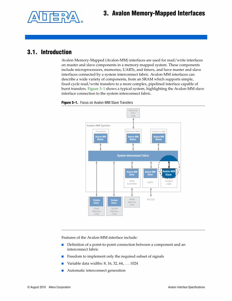
3.1. IntroductionAvalon Memory-Mapped (Avalon-MM) interfaces are used for read/write interfaces on master and slave components in a memory-mapped system. These components include microprocessors, memories, UARTs, and timers, and have master and slave interfaces connected by a system interconnect fabric. Avalon-MM interfaces can describe a wide variety of components, from an SRAM which supports simple, fixed-cycle read/write transfers to a more complex, pipelined interface capable of burst transfers. Figure 3–1 shows a typical system, highlighting the Avalon-MM slave interface connection to the system interconnect fabric.
Features of the Avalon-MM interface include:
■ Definition of a point-to-point connection between a component and an interconnect fabric
■ Freedom to implement only the required subset of signals
■ Variable data widths: 8, 16, 32, 64, . . . 1024
■ Automatic interconnect generation
Figure 3–1. Focus on Avalon-MM Slave Transfers
RS-232
Avalon-MM System
System Interconnect Fabric
EthernetPHYChip
AvalonSlave Port
Avalon-MMSlave
Avalon-MMSlave
RAMMemory
Chip
Avalon-MMMaster
Processor
FlashMemory
Chip
TristateSlave
SRAMMemory
Chip
TristateSlave
Avalon-MMMaster
Avalon-MMMaster
Ethernet MAC Custom Logic
RAMController
UART CustomLogic
Avalon-MMSlave
Avalon Interface Specifications
3–2 Chapter 3: Avalon Memory-Mapped InterfacesSlaves
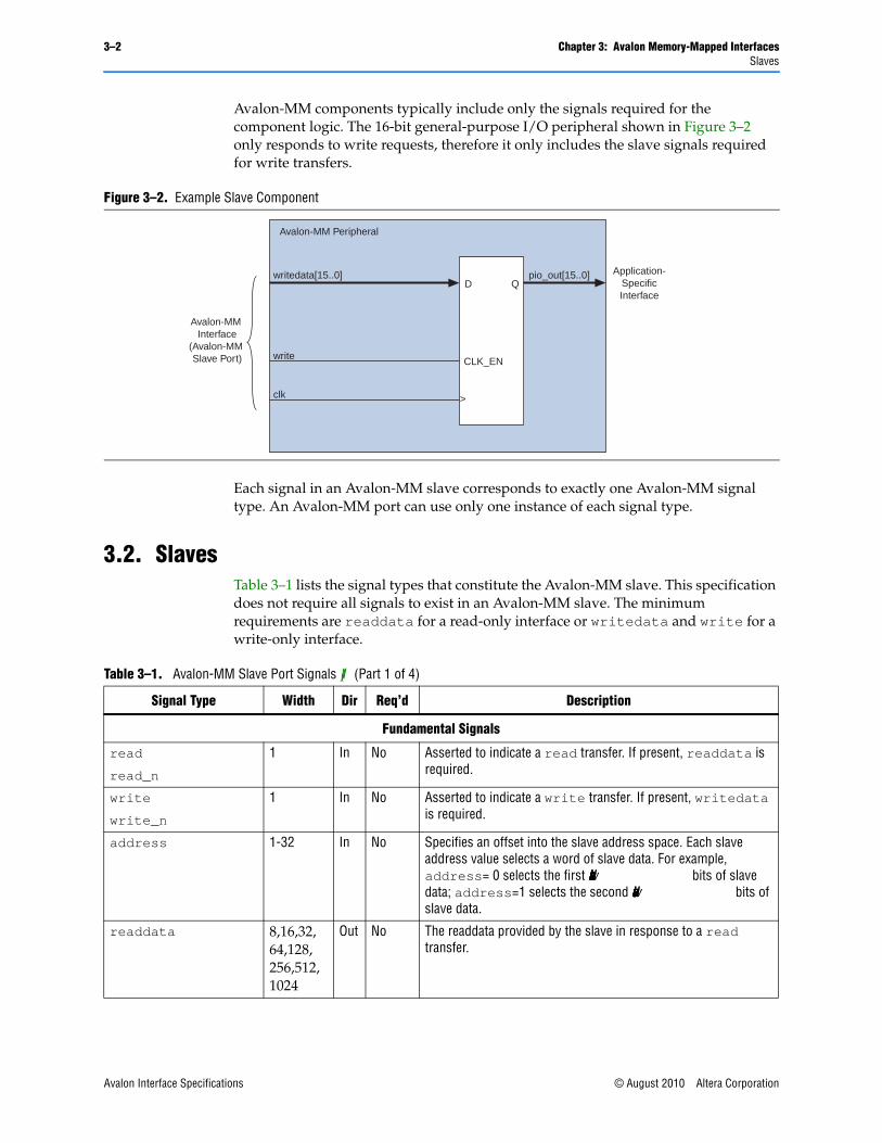
Avalon-MM components typically include only the signals required for the component logic. The 16-bit general-purpose I/O peripheral shown in Figure 3–2 only responds to write requests, therefore it only includes the slave signals required for write transfers.
Each signal in an Avalon-MM slave corresponds to exactly one Avalon-MM signal type. An Avalon-MM port can use only one instance of each signal type.
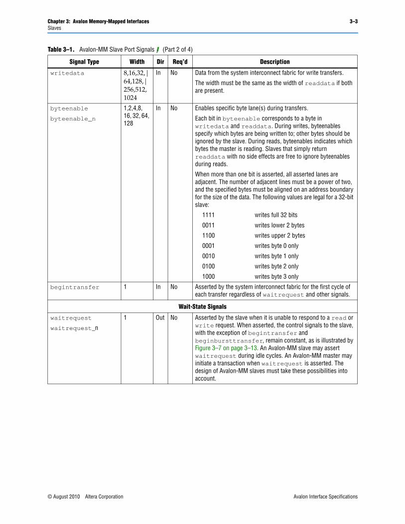
3.2. Slaves Table 3–1 lists the signal types that constitute the Avalon-MM slave. This specification does not require all signals to exist in an Avalon-MM slave. The minimum requirements are readdata for a read-only interface or writedata and write for a write-only interface.
Figure 3–2. Example Slave Component
Avalon-MM Interface
(Avalon-MM Slave Port)
Application-SpecificInterface
writedata[15..0]
write
clk
pio_out[15..0]
CLK_EN
>
D Q
Avalon-MM Peripheral
Table 3–1. Avalon-MM Slave Port Signals (1) (Part 1 of 4)
Signal Type Width Dir Req’d Description
Fundamental Signals
read
read_n
1 In No Asserted to indicate a read transfer. If present, readdata is required.
write
write_n
1 In No Asserted to indicate a write transfer. If present, writedata is required.
address 1-32 In No Specifies an offset into the slave address space. Each slave address value selects a word of slave data. For example, address= 0 selects the first <slave data width> bits of slave data; address=1 selects the second <slave data width> bits of slave data.
readdata 8,16,32,64,128,256,512,1024
Out No The readdata provided by the slave in response to a read transfer.
Avalon Interface Specifications © August 2010 Altera Corporation
Chapter 3: Avalon Memory-Mapped Interfaces 3–3Slaves
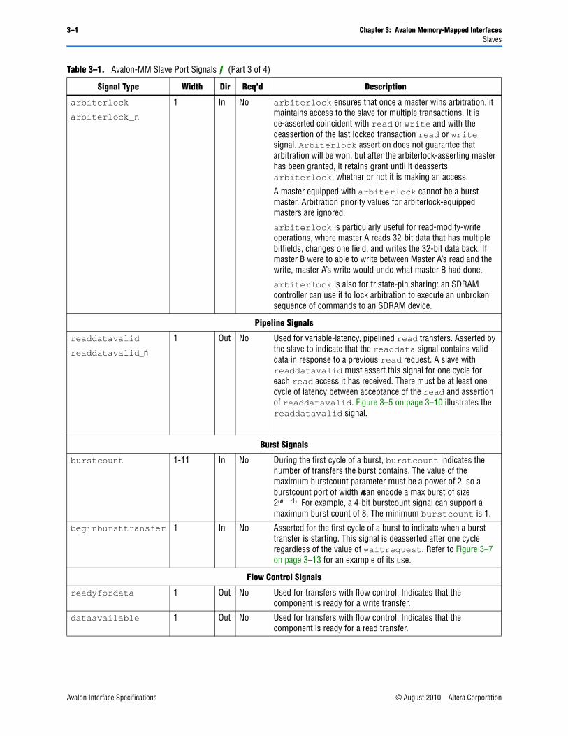
writedata 8,16,32,|64,128,|256,512,1024
In No Data from the system interconnect fabric for write transfers.
The width must be the same as the width of readdata if both are present.
byteenable
byteenable_n
1,2,4,8, 16, 32, 64, 128
In No Enables specific byte lane(s) during transfers.
Each bit in byteenable corresponds to a byte in writedata and readdata. During writes, byteenables specify which bytes are being written to; other bytes should be ignored by the slave. During reads, byteenables indicates which bytes the master is reading. Slaves that simply return readdata with no side effects are free to ignore byteenables during reads.
When more than one bit is asserted, all asserted lanes are adjacent. The number of adjacent lines must be a power of two, and the specified bytes must be aligned on an address boundary for the size of the data. The following values are legal for a 32-bit slave:
1111 writes full 32 bits
0011 writes lower 2 bytes
1100 writes upper 2 bytes
0001 writes byte 0 only
0010 writes byte 1 only
0100 writes byte 2 only
1000 writes byte 3 only
begintransfer 1 In No Asserted by the system interconnect fabric for the first cycle of each transfer regardless of waitrequest and other signals.
Wait-State Signals
waitrequest
waitrequest_n
1 Out No Asserted by the slave when it is unable to respond to a read or write request. When asserted, the control signals to the slave, with the exception of begintransfer and beginbursttransfer, remain constant, as is illustrated by Figure 3–7 on page 3–13. An Avalon-MM slave may assert waitrequest during idle cycles. An Avalon-MM master may initiate a transaction when waitrequest is asserted. The design of Avalon-MM slaves must take these possibilities into account.
Table 3–1. Avalon-MM Slave Port Signals (1) (Part 2 of 4)
Signal Type Width Dir Req’d Description
© August 2010 Altera Corporation Avalon Interface Specifications
3–4 Chapter 3: Avalon Memory-Mapped InterfacesSlaves
arbiterlock
arbiterlock_n
1 In No arbiterlock ensures that once a master wins arbitration, it maintains access to the slave for multiple transactions. It is de-asserted coincident with read or write and with the deassertion of the last locked transaction read or write signal. Arbiterlock assertion does not guarantee that arbitration will be won, but after the arbiterlock-asserting master has been granted, it retains grant until it deasserts arbiterlock, whether or not it is making an access.
A master equipped with arbiterlock cannot be a burst master. Arbitration priority values for arbiterlock-equipped masters are ignored.
arbiterlock is particularly useful for read-modify-write operations, where master A reads 32-bit data that has multiple bitfields, changes one field, and writes the 32-bit data back. If master B were to able to write between Master A’s read and the write, master A’s write would undo what master B had done.
arbiterlock is also for tristate-pin sharing: an SDRAM controller can use it to lock arbitration to execute an unbroken sequence of commands to an SDRAM device.
Pipeline Signals
readdatavalid
readdatavalid_n
1 Out No Used for variable-latency, pipelined read transfers. Asserted by the slave to indicate that the readdata signal contains valid data in response to a previous read request. A slave with readdatavalid must assert this signal for one cycle for each read access it has received. There must be at least one cycle of latency between acceptance of the read and assertion of readdatavalid. Figure 3–5 on page 3–10 illustrates the readdatavalid signal.
Burst Signals
burstcount 1-11 In No During the first cycle of a burst, burstcount indicates the number of transfers the burst contains. The value of the maximum burstcount parameter must be a power of 2, so a burstcount port of width <n> can encode a max burst of size 2(<n> -1). For example, a 4-bit burstcount signal can support a maximum burst count of 8. The minimum burstcount is 1.
beginbursttransfer 1 In No Asserted for the first cycle of a burst to indicate when a burst transfer is starting. This signal is deasserted after one cycle regardless of the value of waitrequest. Refer to Figure 3–7 on page 3–13 for an example of its use.
Flow Control Signals
readyfordata 1 Out No Used for transfers with flow control. Indicates that the component is ready for a write transfer.
dataavailable 1 Out No Used for transfers with flow control. Indicates that the component is ready for a read transfer.
Table 3–1. Avalon-MM Slave Port Signals (1) (Part 3 of 4)
Signal Type Width Dir Req’d Description
Avalon Interface Specifications © August 2010 Altera Corporation
Chapter 3: Avalon Memory-Mapped Interfaces 3–5Slave Interface Properties
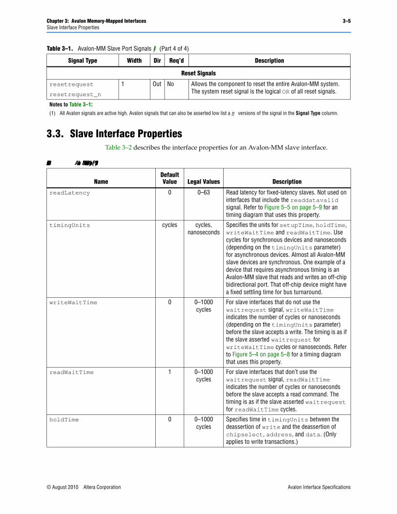
3.3. Slave Interface PropertiesTable 3–2 describes the interface properties for an Avalon-MM slave interface.
Reset Signals
resetrequest
resetrequest_n
1 Out No Allows the component to reset the entire Avalon-MM system. The system reset signal is the logical OR of all reset signals.
Notes to Table 3–1:
(1) All Avalon signals are active high. Avalon signals that can also be asserted low list a _n versions of the signal in the Signal Type column.
Table 3–1. Avalon-MM Slave Port Signals (1) (Part 4 of 4)
Signal Type Width Dir Req’d Description
Table 3–2. Avalon-MM Slave Interface Properties (Part 1 of 2)
NameDefault Value Legal Values Description
readLatency 0 0–63 Read latency for fixed-latency slaves. Not used on interfaces that include the readdatavalid signal. Refer to Figure 5–5 on page 5–9 for an timing diagram that uses this property.
timingUnits cycles cycles, nanoseconds
Specifies the units for setupTime, holdTime, writeWaitTime and readWaitTime. Use cycles for synchronous devices and nanoseconds (depending on the timingUnits parameter) for asynchronous devices. Almost all Avalon-MM slave devices are synchronous. One example of a device that requires asynchronous timing is an Avalon-MM slave that reads and writes an off-chip bidirectional port. That off-chip device might have a fixed settling time for bus turnaround.
writeWaitTime 0 0–1000 cycles
For slave interfaces that do not use the waitrequest signal, writeWaitTime indicates the number of cycles or nanoseconds (depending on the timingUnits parameter) before the slave accepts a write. The timing is as if the slave asserted waitrequest for writeWaitTime cycles or nanoseconds. Refer to Figure 5–4 on page 5–8 for a timing diagram that uses this property.
readWaitTime 1 0–1000 cycles
For slave interfaces that don’t use the waitrequest signal, readWaitTime indicates the number of cycles or nanoseconds before the slave accepts a read command. The timing is as if the slave asserted waitrequest for readWaitTime cycles.
holdTime 0 0–1000 cycles
Specifies time in timingUnits between the deassertion of write and the deassertion of chipselect, address, and data. (Only applies to write transactions.)
© August 2010 Altera Corporation Avalon Interface Specifications

3–6 Chapter 3: Avalon Memory-Mapped InterfacesSlave Timing
3.4. Slave TimingThis section describes issues related to timing and sequencing of Avalon-MM slave signals.
3.4.1. Synchronous InterfaceThe Avalon-MM interface is a synchronous protocol. Each Avalon-MM port is synchronized to an associated clock interface. Signals may be combinational if they are driven from the outputs of registers that are synchronous to the clock signal. An Avalon-MM component must not be sensitive to any signal besides the reference clock. This document does not dictate how or when signals transition between clock edges and timing diagrams are devoid of fine-grained timing information.
setupTime 0 0–1000 cycles
Specifies time in timingUnits between the assertion of chipselect, address, and data and assertion of read or write.
maximumPendingReadTransactions
1 (1) 1–64 The maximum number of pending reads which can be queued up by the slave. Refer to Figure 3–5 on page 3–10 for a timing diagram that uses this property.
burstOnBurstBoundariesOnly false true,false If true, burst transfers presented to this interface are guaranteed to begin at addresses which are multiples of the burst size.
linewrapBursts false true,false If true, indicates that the slave implements a line wrapping burst instead of an incrementing burst. With a wrapping burst, when the address reaches a burst boundary, it wraps back to the previous burst boundary such that only the low order bits need to be used for addressing. To address 0xC, a wrapping burst with burst boundaries every 32 bytes across a 32-bit interface would write to addresses 0xC, 0x10, 0x14, 0x18, 0x1C, 0x0, 0x4, and 0x8.
maxBurstSize 1 64 The maximum burst size that a slave can accept.
bridgesToMaster null Avalon-MM master on the same component
An Avalon-MM bridge consists of a slave and a master, and has the property that an access to the slave requesting a particular byte or bytes will cause the same byte or bytes to be requested by the master.
associatedClock — — Name of the clock interface that this Avalon-MM slave interface is synchronous to.
Note to Table 3–2:
(1) If a component accepts more read transfers than the value indicated here, the internal pending read FIFO may overflow, causing the system to lockup.
Table 3–2. Avalon-MM Slave Interface Properties (Part 2 of 2)
NameDefault Value Legal Values Description
Avalon Interface Specifications © August 2010 Altera Corporation
Chapter 3: Avalon Memory-Mapped Interfaces 3–7Slave Transfers
3.4.2. PerformanceThere is no guaranteed performance of the Avalon-MM interface. The maximum performance is dependent on component design and system implementation.
3.4.3. Electrical CharacteristicsThe Avalon-MM interface specification does not specify any electrical characteristics.
3.5. Slave TransfersThis section defines two basic concepts before introducing the slave transfer types.
■ Transfer—A transfer is a read or write operation of a word of data, between an Avalon-MM slave and the system interconnect fabric. Avalon-MM transfers words ranging in size from 8–1024 bits. Transfers take one or more clock cycles to complete.
Both masters and slaves are part of a transfer; the Avalon-MM master initiates the transfer and the Avalon-MM slave responds to it.
■ Master-slave pair —This term refers to the master port and slave port involved in a transfer. During a transfer, the master port's control and data signals pass through the system interconnect fabric and interact with the slave port.
3.5.1. Typical Slave Read and Write Transfers This section describes a typical Avalon-MM slave that supports read and write transfers with slave-controlled waitrequest. The slave can stall the system interconnect fabric for as many cycles as required by asserting the waitrequest signal. If a slave uses waitrequest for either read or write transfers, it must use waitrequest for both.
The slave receives address, byteenable, read or write, and writedata after the rising edge of the clock. The slave port must assert waitrequest before the next rising clock edge to hold off the transfers. When the slave asserts waitrequest, the transfer is delayed and the address and control signals are held constant. Transfers complete on the rising edge of the first clk after the slave port deasserts waitrequest.
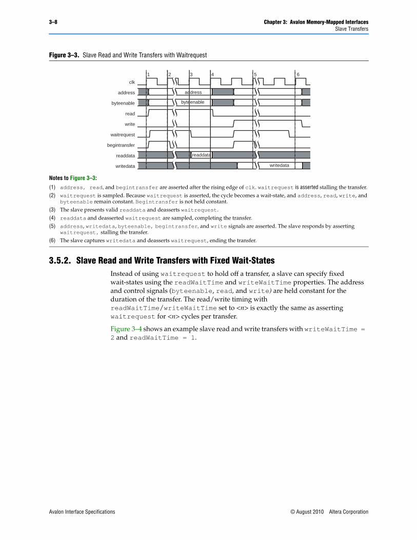
There is no limit on how long a slave port can stall. Therefore, you must ensure that a slave port does not assert waitrequest indefinitely. Figure 3–3 shows read and write transfers using waitrequest.
© August 2010 Altera Corporation Avalon Interface Specifications
3–8 Chapter 3: Avalon Memory-Mapped InterfacesSlave Transfers
3.5.2. Slave Read and Write Transfers with Fixed Wait-StatesInstead of using waitrequest to hold off a transfer, a slave can specify fixed wait-states using the readWaitTime and writeWaitTime properties. The address and control signals (byteenable, read, and write) are held constant for the duration of the transfer. The read/write timing with readWaitTime/writeWaitTime set to <n> is exactly the same as asserting waitrequest for <n> cycles per transfer.
Figure 3–4 shows an example slave read and write transfers with writeWaitTime = 2 and readWaitTime = 1.
Figure 3–3. Slave Read and Write Transfers with Waitrequest
Notes to Figure 3–3:
(1) address, read, and begintransfer are asserted after the rising edge of clk. waitrequest is asserted stalling the transfer. (2) waitrequest is sampled. Because waitrequest is asserted, the cycle becomes a wait-state, and address, read, write, and
byteenable remain constant. Begintransfer is not held constant.(3) The slave presents valid readdata and deasserts waitrequest.(4) readdata and deasserted waitrequest are sampled, completing the transfer.(5) address, writedata, byteenable, begintransfer, and write signals are asserted. The slave responds by asserting
waitrequest, stalling the transfer.(6) The slave captures writedata and deasserts waitrequest, ending the transfer.
clk
address
byteenable
read
write
waitrequest
begintransfer
readdata
writedata
address
byteenable
readdata
writedata
1 2 3 4 5 6
Avalon Interface Specifications © August 2010 Altera Corporation

Chapter 3: Avalon Memory-Mapped Interfaces 3–9Slave Transfers
Transfers with a single wait-state are commonly used for synchronous, on-chip peripherals. The peripheral can capture address and control signals on the rising edge of clk, and has one full cycle to return data. Components with zero wait-states are allowed, but may decrease achievable frequency because they generate the response in the same cycle as the request.
3.5.3. Pipelined TransfersAvalon-MM pipelined read transfers increase the throughput for synchronous slave devices that require several cycles to return data for the first access, but can return one data value per cycle for some time thereafter. New pipelined read transfers can be started before readdata for the previous transfers is returned. Write transfers cannot be pipelined.
A pipelined read transfer is divided into two phases: an address phase and a data phase. A master initiates a transfer by presenting the address during the address phase; a slave port fulfills the transfer by delivering the data during the data phase. The address phase for a new transfer (or multiple transfers) can begin before the data phase of a previous transfer completes. This delay is called pipeline latency, which is the duration from the end of the address phase to the beginning of the data phase.
The key differences between how wait-states and pipeline latency affect transfer timing is as follows:
■ Wait-states—Wait-states determine the length of the address phase, and limit the maximum throughput of a port. If a slave requires one wait-state to respond to a transfer request, then the port requires at least two clock cycles per transfer.
■ Pipeline Latency—Pipeline latency determines the time until data is returned independently of the address phase. A pipelined slave port with no wait-states can sustain one transfer per cycle, even though it may require several cycles of latency to return the first unit of data.
Wait-states and pipelined reads can be supported concurrently, and pipeline latency can be either fixed or variable, as discussed in the following sections.
Figure 3–4. Slave Read and Write Transfer with Fixed Wait-States
Notes to Figure 3–4:
(1) The master asserts address and read on the rising edge of clk.(2) The next rising edge of clk marks the end of the first and only wait-state cycle because the readWaitTime is 1. (3) The slave captures readdata on the rising edge of clk, and the read transfer ends.(4) writedata, address, byteenable, and write signals are available to the slave. (5) Because writeWaitTime is 2, the transfer terminates after completing. The data and control signals are held constant until this
time.
clk
address
byteenable
read
write
readdata
writedata
address address
readdata
writedata
4 51 2 3
© August 2010 Altera Corporation Avalon Interface Specifications
3–10 Chapter 3: Avalon Memory-Mapped InterfacesSlave Transfers
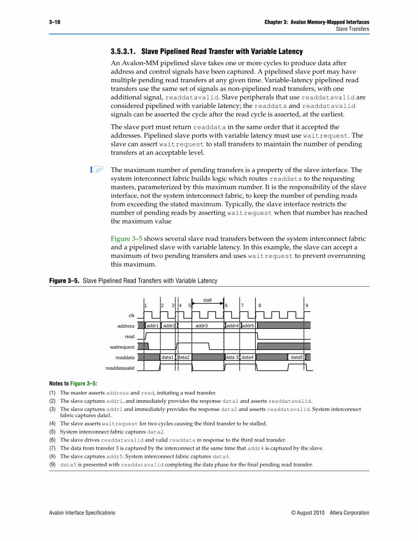
3.5.3.1. Slave Pipelined Read Transfer with Variable LatencyAn Avalon-MM pipelined slave takes one or more cycles to produce data after address and control signals have been captured. A pipelined slave port may have multiple pending read transfers at any given time. Variable-latency pipelined read transfers use the same set of signals as non-pipelined read transfers, with one additional signal, readdatavalid. Slave peripherals that use readdatavalid are considered pipelined with variable latency; the readdata and readdatavalid signals can be asserted the cycle after the read cycle is asserted, at the earliest.
The slave port must return readdata in the same order that it accepted the addresses. Pipelined slave ports with variable latency must use waitrequest. The slave can assert waitrequest to stall transfers to maintain the number of pending transfers at an acceptable level.
1 The maximum number of pending transfers is a property of the slave interface. The system interconnect fabric builds logic which routes readdata to the requesting masters, parameterized by this maximum number. It is the responsibility of the slave interface, not the system interconnect fabric, to keep the number of pending reads from exceeding the stated maximum. Typically, the slave interface restricts the number of pending reads by asserting waitrequest when that number has reached the maximum value
Figure 3–5 shows several slave read transfers between the system interconnect fabric and a pipelined slave with variable latency. In this example, the slave can accept a maximum of two pending transfers and uses waitrequest to prevent overrunning this maximum.
Figure 3–5. Slave Pipelined Read Transfers with Variable Latency
Notes to Figure 3–5:
(1) The master asserts address and read, initiating a read transfer. (2) The slave captures addr1, and immediately provides the response data1 and asserts readdatavalid. (3) The slave captures addr2 and immediately provides the response data2 and asserts readdatavalid. System interconnect
fabric captures data1.(4) The slave asserts waitrequest for two cycles causing the third transfer to be stalled.(5) System interconnect fabric captures data2.(6) The slave drives readdatavalid and valid readdata in response to the third read transfer.(7) The data from transfer 3 is captured by the interconnect at the same time that addr4 is captured by the slave.(8) The slave captures addr5. System interconnect fabric captures data4. (9) data5 is presented with readdatavalid completing the data phase for the final pending read transfer.
clk
address
read
waitrequest
readdata
readdatavalid
1 2 3 4 5 6 7 98
addr1 addr2 addr3
stall
addr4 addr5
data1 data2 data 3 data4 data5
Avalon Interface Specifications © August 2010 Altera Corporation

Chapter 3: Avalon Memory-Mapped Interfaces 3–11Slave Transfers
If the slave cannot handle a write transfer while it is processing pending read transfers, the slave must assert its waitrequest and stall the write operation until the pending read transfers have completed. The Avalon-MM specification does not define the value of readdata in the event that a slave accepts a write transfer to the same address as a currently pending read transfer. Pipelined slaves with variable latency must support waitrequest.
3.5.3.2. Slave Pipelined Read Transfer with Fixed Latency The address phase for fixed latency slave read transfers is identical to the variable latency case. After the address phase, a pipelined slave port with fixed read latency takes a fixed number of clock cycles to return valid readdata, as indicated by the readWaitTime property. The system interconnect fabric captures readdata on the appropriate rising clock edge, and the data phase ends.
During the address phase, the slave port can assert waitrequest to hold off the transfer or can specify readWaitTime for a fixed number of wait states. The address phase ends on the next rising edge of clk after wait-states, if any.
During the data phase, the slave drives readdata after a fixed latency. If the slave has a read latency of <n>, the slave port must present valid readdata on the <nth> rising edge of clk after the end of the address phase.
Figure 3–6 shows multiple data transfers to a slave pipelined port that uses waitrequest and has a fixed read latency of 2 cycles.
3.5.4. Burst TransferA burst executes multiple transfers as a unit, rather than treating every word independently. Bursts may increase throughput for slave ports that achieve greater efficiency when handling multiple word at a time, such as DDR. The net effect of bursting is to lock the arbitration for the duration of the burst. If a slave provides both read and write functionality and supports bursting, it must support both burst reads and burst writes.
Figure 3–6. Slave Pipelined Read Transfer with Fixed Latency of Two Cycles
Notes to Figure 3–6:
(1) A master initiates a read transfer by asserting read and addr1. The slave asserts waitrequest to hold off the transfer for one cycle.
(2) The slave deasserts waitrequest and captures addr1 at the rising edge of clk. The address phase ends here.(3) The slave presents valid readdata after 2 cycles, ending the transfer. (4) addr2 and read are asserted for a new read transfer.(5) The master initiates a third read transfer during the next cycle, before the data from the prior transfer is returned.
clk
address
read
waitrequest
readdata
addr1 addr2 addr3
data1 data2 data3
1 2 3 4 5
© August 2010 Altera Corporation Avalon Interface Specifications

3–12 Chapter 3: Avalon Memory-Mapped InterfacesSlave Transfers
To support bursts, an Avalon-MM slave includes a burstcount input signal. If a slave has a burstcount input, it is considered burst capable.
The burstcount signal behaves as follows:
■ At the start of a burst, burstcount presents the number of sequential transfers in the burst.
■ For width <n> of burstcount, the maximum burst length is 2<n> -1. The minimum legal burst length is one.
To support slave read bursts, a slave must also support:
■ wait-states with the waitrequest signal.
■ Pipelined transfers with variable latency with the readdatavalid signal.
At the start of a burst, the slave sees the address and a burst length value on burstcount. For a burst with an address of <a> and a burstcount value of <b>, the slave must perform <b> consecutive transfers starting at address <a>. The burst completes after the slave receives (write) or returns (read) the <Bth> word of data. The bursting slave must capture address and burstcount only once for each burst. The slave logic must infer the address for all but the first transfers in the burst. A slave can also use the input signal beginbursttransfer, which the system interconnect fabric asserts for the first cycle of each burst.
3.5.4.1. Slave Write BurstsThese rules apply when a slave write burst begins with burstcount greater than one:
■ If a burstcount of <n> is presented at the beginning of the burst, then the slave must accept <n> successive units of writedata to complete the burst. Arbitration between the master-slave pair is locked until the burst completes, guaranteeing that data arrives, in order, from the master port that initiated the burst.
■ The slave must only capture writedata when write is asserted. During the burst, write can be deasserted to indicate that it is not presenting valid writedata. Deasserting write does not terminate the burst; it only delays it.
■ The slave can delay a transfer by asserting waitrequest which forces writedata, write, and byteenable to be held constant, as usual.
■ The functionality of the byteenable signal is the same for bursting and non-bursting slaves. For a 32-bit master burst-writing to a 64-bit slave, starting at byte address 4, the first write transfer seen by the slave is at its address 0, with byteenable = 8b’11110000.
■ The byteenable signals do not all have to be asserted. A burst master writing unaligned data can use the byteenable signal to identify the data being written.
Avalon Interface Specifications © August 2010 Altera Corporation
Chapter 3: Avalon Memory-Mapped Interfaces 3–13Slave Transfers
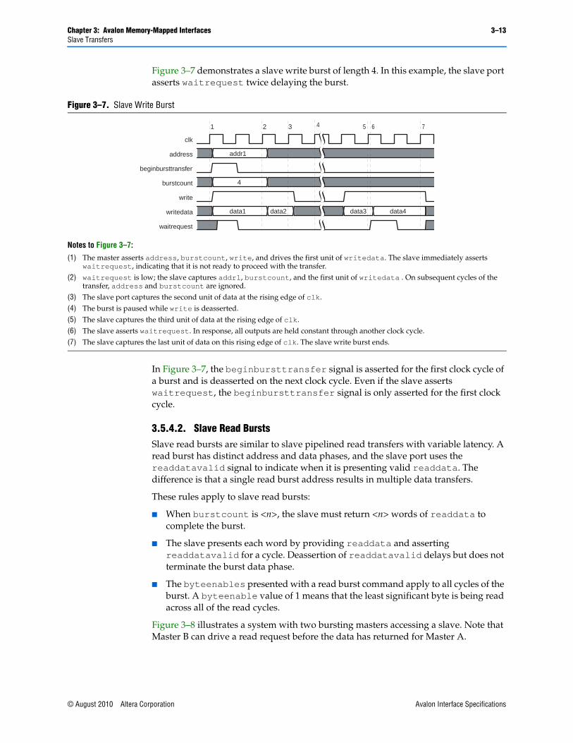
Figure 3–7 demonstrates a slave write burst of length 4. In this example, the slave port asserts waitrequest twice delaying the burst.
In Figure 3–7, the beginbursttransfer signal is asserted for the first clock cycle of a burst and is deasserted on the next clock cycle. Even if the slave asserts waitrequest, the beginbursttransfer signal is only asserted for the first clock cycle.
3.5.4.2. Slave Read BurstsSlave read bursts are similar to slave pipelined read transfers with variable latency. A read burst has distinct address and data phases, and the slave port uses the readdatavalid signal to indicate when it is presenting valid readdata. The difference is that a single read burst address results in multiple data transfers.
These rules apply to slave read bursts:
■ When burstcount is <n>, the slave must return <n> words of readdata to complete the burst.
■ The slave presents each word by providing readdata and asserting readdatavalid for a cycle. Deassertion of readdatavalid delays but does not terminate the burst data phase.
■ The byteenables presented with a read burst command apply to all cycles of the burst. A byteenable value of 1 means that the least significant byte is being read across all of the read cycles.
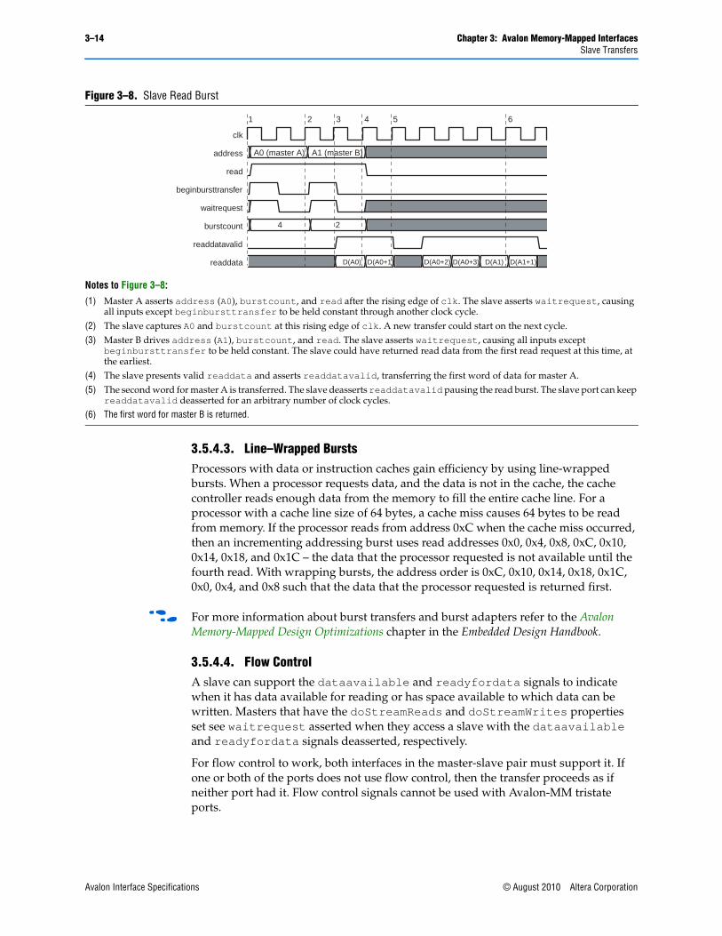
Figure 3–8 illustrates a system with two bursting masters accessing a slave. Note that Master B can drive a read request before the data has returned for Master A.
Figure 3–7. Slave Write Burst
Notes to Figure 3–7:
(1) The master asserts address, burstcount, write, and drives the first unit of writedata. The slave immediately asserts waitrequest, indicating that it is not ready to proceed with the transfer.
(2) waitrequest is low; the slave captures addr1, burstcount, and the first unit of writedata . On subsequent cycles of the transfer, address and burstcount are ignored.
(3) The slave port captures the second unit of data at the rising edge of clk.(4) The burst is paused while write is deasserted. (5) The slave captures the third unit of data at the rising edge of clk.(6) The slave asserts waitrequest. In response, all outputs are held constant through another clock cycle. (7) The slave captures the last unit of data on this rising edge of clk. The slave write burst ends.
clk
address
beginbursttransfer
burstcount
write
writedata
waitrequest
addr1
4
data1 data2 data3 data4
1 2 3 4 65 7
© August 2010 Altera Corporation Avalon Interface Specifications
3–14 Chapter 3: Avalon Memory-Mapped InterfacesSlave Transfers
3.5.4.3. Line–Wrapped BurstsProcessors with data or instruction caches gain efficiency by using line-wrapped bursts. When a processor requests data, and the data is not in the cache, the cache controller reads enough data from the memory to fill the entire cache line. For a processor with a cache line size of 64 bytes, a cache miss causes 64 bytes to be read from memory. If the processor reads from address 0xC when the cache miss occurred, then an incrementing addressing burst uses read addresses 0x0, 0x4, 0x8, 0xC, 0x10, 0x14, 0x18, and 0x1C – the data that the processor requested is not available until the fourth read. With wrapping bursts, the address order is 0xC, 0x10, 0x14, 0x18, 0x1C, 0x0, 0x4, and 0x8 such that the data that the processor requested is returned first.
f For more information about burst transfers and burst adapters refer to the Avalon Memory-Mapped Design Optimizations chapter in the Embedded Design Handbook.
3.5.4.4. Flow ControlA slave can support the dataavailable and readyfordata signals to indicate when it has data available for reading or has space available to which data can be written. Masters that have the doStreamReads and doStreamWrites properties set see waitrequest asserted when they access a slave with the dataavailable and readyfordata signals deasserted, respectively.
For flow control to work, both interfaces in the master-slave pair must support it. If one or both of the ports does not use flow control, then the transfer proceeds as if neither port had it. Flow control signals cannot be used with Avalon-MM tristate ports.
Figure 3–8. Slave Read Burst
Notes to Figure 3–8:
(1) Master A asserts address (A0), burstcount, and read after the rising edge of clk. The slave asserts waitrequest, causing all inputs except beginbursttransfer to be held constant through another clock cycle.
(2) The slave captures A0 and burstcount at this rising edge of clk. A new transfer could start on the next cycle. (3) Master B drives address (A1), burstcount, and read. The slave asserts waitrequest, causing all inputs except
beginbursttransfer to be held constant. The slave could have returned read data from the first read request at this time, at the earliest.
(4) The slave presents valid readdata and asserts readdatavalid, transferring the first word of data for master A.(5) The second word for master A is transferred. The slave deasserts readdatavalid pausing the read burst. The slave port can keep
readdatavalid deasserted for an arbitrary number of clock cycles.(6) The first word for master B is returned.
clk
address
read
beginbursttransfer
waitrequest
burstcount
readdatavalid
readdata
A0 (master A) A1 (master B)
4 2
D(A0) D(A0+1) D(A0+2) D(A0+3) D(A1) D(A1+1)
2 3 5 61 4
Avalon Interface Specifications © August 2010 Altera Corporation
Chapter 3: Avalon Memory-Mapped Interfaces 3–15Address Alignment
In a master-slave pair that uses flow control, after a master port initiates a transfer, the system interconnect fabric initiates a transfer with the target slave port only if the readyfordata or dataavailable signals indicate that the slave port it is ready for the transfer. While the slave port is not ready, the system interconnect fabric forces the master port to wait.
A slave port can assert dataavailable at any time to indicate that it has read data available. While dataavailable is asserted, a new transfer from a master port with flow control can begin on the next rising edge of clk. A slave port can only deassert dataavailable at the end of a read transfer. The signal is immediately valid for successive transfers that might follow.
A slave port can assert readyfordata at any time to indicate that it can accept write data. While readyfordata is asserted, a new transfer from a master port with flow control can begin on the next rising edge of clk.
1 Flow control is a deprecated feature. Altera recommends that you use the Avalon Streaming (Avalon-ST) and the ready and valid signals for new designs. For more information about Avalon-ST interfaces refer to Chapter 6, Avalon Streaming Interfaces.
3.6. Address Alignment For systems in which master and slave data widths differ, the system interconnect manages address alignment issues. The Avalon-MM interface resolves data width differences, so that any master port can communicate with any slave port, regardless of the respective data widths.
3.6.1. Avalon-MM Slave AddressingDynamic bus sizing refers to a service provided by the system interconnect fabric that dynamically manages data during transfers between master-slave pairs of differing data widths, such that all slave data are aligned in contiguous bytes in the master address space.
If the master is wider than the slave, data bytes in the master address space map to multiple locations in the slave address space. For example, when a 32-bit master port performs a read transfer from a 16-bit slave port, the system interconnect fabric executes two read transfers on the slave side on consecutive addresses, and presents 32-bits of slave data back to the master port.
If the master is narrower than the slave, then the system interconnect fabric manages the slave byte lanes. During master read transfers, the system interconnect fabric presents only the appropriate byte lanes of slave data to the narrower master. During master write transfers, the system interconnect fabric automatically asserts the byteenable signals to write data only to the specified slave byte lanes.
Slaves must have a data width of 8, 16, 32, 64, 128, 256, 512 or 1024 bits. Table 3–3 shows how slave data of various widths is aligned within a 32-bit master. In Table 3–3, OFFSET[N] refers to a slave word size offset into the slave address space.
© August 2010 Altera Corporation Avalon Interface Specifications

3–16 Chapter 3: Avalon Memory-Mapped InterfacesAddress Alignment
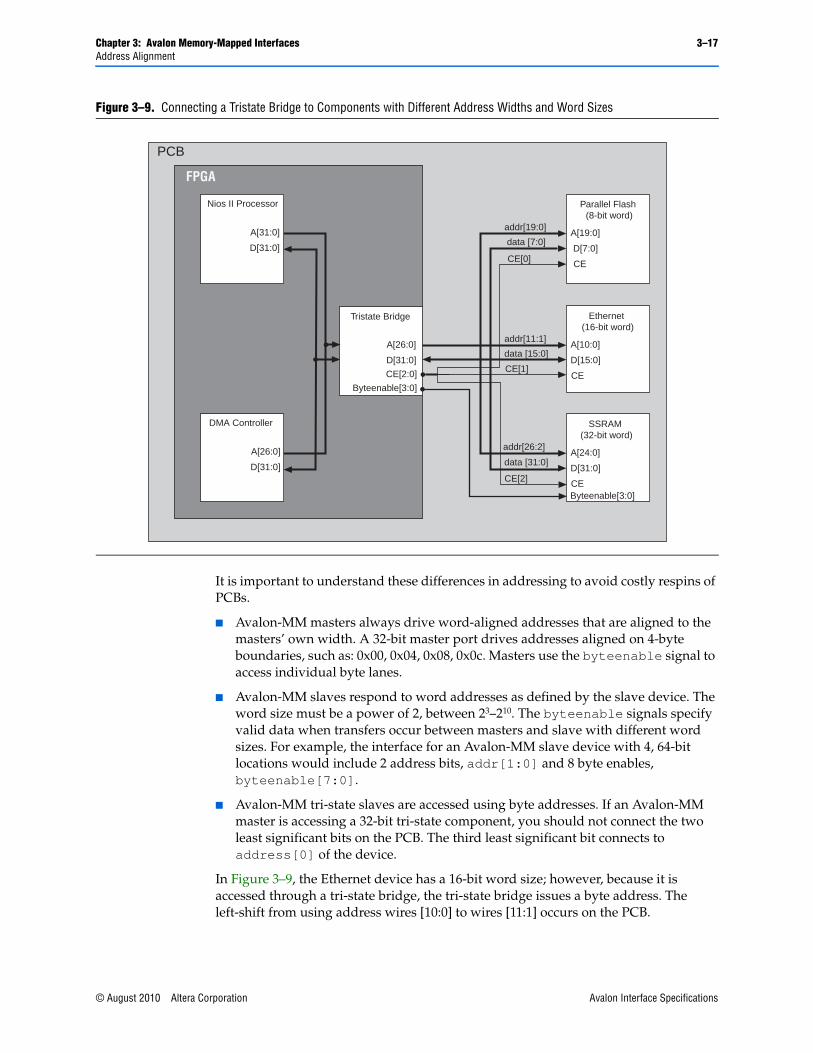
3.6.2. Avalon-MM Tri-State Slave AddressingIn contrast to Avalon-MM slaves which are accessed using the word size that the Avalon-MM slave defines, Avalon-MM tri-state slaves are accessed using byte addresses. Using byte addresses allows multiple slave devices with different word sizes to be connected to the same address pins of the FPGA. Figure 3–9 illustrates this point.
Table 3–3. Dynamic Bus Sizing Master-to-Slave Address Mapping
Master Byte Address (1)
32-Bit Master Data
When Accessing an 8-Bit Slave Port
When Accessing a 16-Bit Slave Port
When Accessing a 64-Bit Slave Port
0x00 OFFSET[3]7..0:OFFSET[2]7..0:OFFSET[1]7..0:OFFSET[0]7..0
OFFSET[1]15..0:OFFSET[0]15..0 (2) OFFSET[0]31..0
0x04 OFFSET[7]7..0:OFFSET[6]7..0:OFFSET[5]7..0:OFFSET[4]7..0
OFFSET[3]15..0:OFFSET[2]15..0 OFFSET[0]63..32
0x08 OFFSET[11]7..0:OFFSET[10]7..0:OFFSET[9]7..0:OFFSET[8]7..0
OFFSET[5]15..0:OFFSET[4]15..0 OFFSET[1]31..0
0x0C OFFSET[15]7..0:OFFSET[14]7..0:OFFSET[13]7..0:OFFSET[12]7..0
OFFSET[7]15..0:OFFSET[6]15..0 OFFSET[1]63..32
... ... ...
Notes to Table 3–3:
(1) Although the master is issuing byte addresses, it is accessing full 32-bit words.(2) For all slave entries, [<n>] is the word offset and the subscript values are the bits in the word.
Avalon Interface Specifications © August 2010 Altera Corporation
Chapter 3: Avalon Memory-Mapped Interfaces 3–17Address Alignment
It is important to understand these differences in addressing to avoid costly respins of PCBs.
■ Avalon-MM masters always drive word-aligned addresses that are aligned to the masters’ own width. A 32-bit master port drives addresses aligned on 4-byte boundaries, such as: 0x00, 0x04, 0x08, 0x0c. Masters use the byteenable signal to access individual byte lanes.
■ Avalon-MM slaves respond to word addresses as defined by the slave device. The word size must be a power of 2, between 23–210. The byteenable signals specify valid data when transfers occur between masters and slave with different word sizes. For example, the interface for an Avalon-MM slave device with 4, 64-bit locations would include 2 address bits, addr[1:0] and 8 byte enables, byteenable[7:0].
■ Avalon-MM tri-state slaves are accessed using byte addresses. If an Avalon-MM master is accessing a 32-bit tri-state component, you should not connect the two least significant bits on the PCB. The third least significant bit connects to address[0] of the device.
In Figure 3–9, the Ethernet device has a 16-bit word size; however, because it is accessed through a tri-state bridge, the tri-state bridge issues a byte address. The left-shift from using address wires [10:0] to wires [11:1] occurs on the PCB.
Figure 3–9. Connecting a Tristate Bridge to Components with Different Address Widths and Word Sizes
data [7:0]
addr[19:0]
CE[0]
Parallel Flash (8-bit word)
CE
A[19:0]
D[7:0]
data [15:0]
addr[11:1]
CE[1]CE[2:0]
Ethernet (16-bit word)
Tristate Bridge
PCB
CE
A[10:0]
D[15:0]
data [31:0]
addr[26:2]
CE[2]
SSRAM (32-bit word)
CEByteenable[3:0]
Byteenable[3:0]
A[24:0]
D[31:0]
Nios II Processor
A[31:0]
D[31:0]
DMA Controller
A[26:0]
D[31:0]
A[26:0]
D[31:0]
FPGA
© August 2010 Altera Corporation Avalon Interface Specifications

3–18 Chapter 3: Avalon Memory-Mapped InterfacesMasters
3.6.3. Native Addressing In versions of the SOPC Builder software before v8.0, a slave interface could specify that it had native addressing. When a master port addresses a slave port with the native address alignment property, all slave data is aligned on native master address boundaries. When a master port reads from a narrower slave port, the slave data bits map to the lower bits of the master data, and the upper master data bits are padded with zero. During write transfers, the upper bits are ignored. For example, if a 16-bit master port reads an 8-bit slave port, the readdata signal is of the form 0x00<nn>, where <n> represents valid data, meaning that each word address as seen by each master addresses a different word on the slave. When a 32-bit master accesses a 64-bit slave, the upper 32 bits get coded to 0. Depending on how the slave handles the data, this coding could have negative side-effects.
With native addressing, the effective address map of the slave is dependent on the master that is accessing it, and in some cases, the address span of the slave changes as masters are added to the system. In many cases, extra logic is required to handle accesses from different masters, leading to increased logic usage and performance degradation.
1 Native addressing is now deprecated, meaning that it is still supported by the system interconnect fabric, but is not recommended for new components.
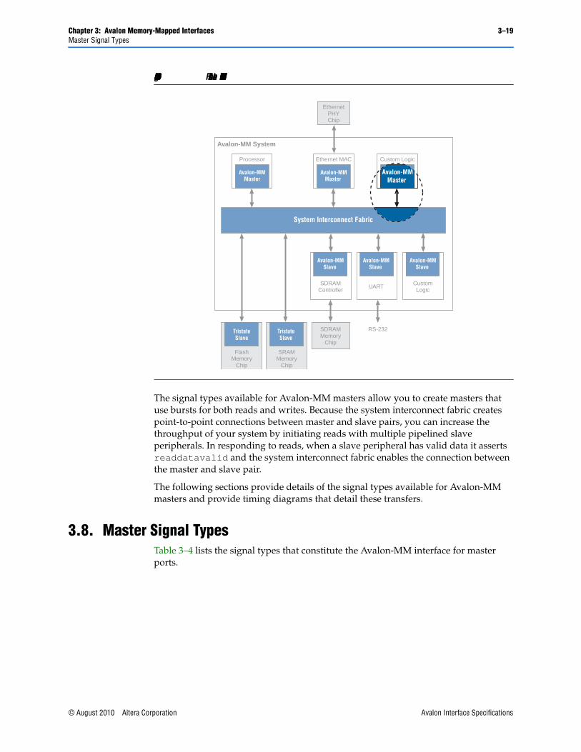
3.7. Masters This section defines the behavior of Avalon-MM master transfers between a master and the system interconnect fabric as shown in Figure 3–10.
Avalon Interface Specifications © August 2010 Altera Corporation
Chapter 3: Avalon Memory-Mapped Interfaces 3–19Master Signal Types
The signal types available for Avalon-MM masters allow you to create masters that use bursts for both reads and writes. Because the system interconnect fabric creates point-to-point connections between master and slave pairs, you can increase the throughput of your system by initiating reads with multiple pipelined slave peripherals. In responding to reads, when a slave peripheral has valid data it asserts readdatavalid and the system interconnect fabric enables the connection between the master and slave pair.
The following sections provide details of the signal types available for Avalon-MM masters and provide timing diagrams that detail these transfers.
3.8. Master Signal TypesTable 3–4 lists the signal types that constitute the Avalon-MM interface for master ports.
Figure 3–10. Focus of Avalon-MM Master Transfers
RS-232
Avalon-MM System
System Interconnect Fabric
EthernetPHYChip
Avalon-MMSlave
Avalon-MMSlave
Avalon-MMSlave
SDRAMMemory
Chip
Avalon-MMMaster
Processor
FlashMemory
Chip
TristateSlave
SRAMMemory
Chip
TristateSlave
Avalon-MMMaster
AvalonMaster Port
Ethernet MAC Custom Logic
SDRAMController
UART CustomLogic
Avalon-MMMaster
© August 2010 Altera Corporation Avalon Interface Specifications

3–20 Chapter 3: Avalon Memory-Mapped InterfacesMaster Signal Types
Table 3–4. Avalon-MM Master Signals (Part 1 of 3)
Signal Type Width Direction Req’d Description
Fundamental Signals
address 1-32 Out Yes The address signal represents a byte address regardless of the data-width of the master. The value of the address must be aligned to the data width. To write to specific bytes within a data word, the master must use the byteenable signal.
Masters always issue byte addresses, regardless of the data width of the master or slave port. The system interconnect fabric translates this address into a word address in the slave’s address space so that each slave access is for a word of data from the perspective of the slave.
read
read_n
1 Out No Read request signal from the master. Not required if the master never performs read transfers.
If present, readdata must also be present.
readdata 8,16,32,64, 128, 256, 512, 1024
In No Data signal for read transfers.
write
write_n
1 Out No Write request signal from the master. Not required if the master never performs write transfers.
If present, writedata must also be used.
writedata 8,16,32,64, 128, 256, 512, 1024
Out No Data signal from the master for write transfers. Not required if the master never performs write transfers. If readdata is also present, readdata and writedata must be the same width.
byteenable
byteenable_n
1, 2,4,8, 16, 32, 64, 128
Out No Enables specific byte lanes during transfers on ports of width greater than 8 bits. Each bit in byteenable corresponds to a byte lane in writedata and readdata. The master bit <n> of byteenable indicates whether byte <n> is being written to. During writes, byteenables specify which bytes to write. Other bytes should be ignored by the slave. During reads, byteenables indicates which bytes the master is reading.
When more than one byte lane is asserted, all asserted lanes must be adjacent. The number of adjacent lines must be a power of 2, and the specified bytes must be aligned on an address boundary for the size of the data. The are legal values for a 32-bit slave:
1111 writes full 32 bits
0011 writes lower 2 bytes
1100 writes upper 2 bytes
0001 writes byte 0 only
0010 writes byte 1 only
0100 writes byte 2 only
1000 writes byte 3 only
Avalon Interface Specifications © August 2010 Altera Corporation
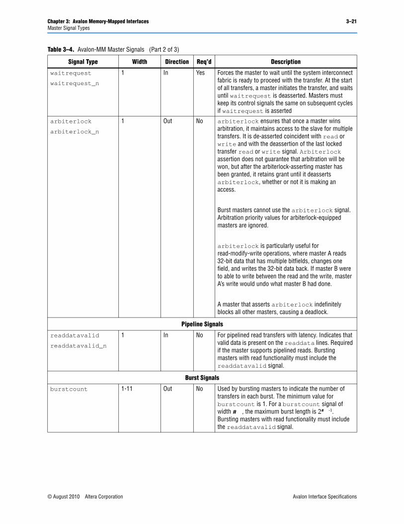
Chapter 3: Avalon Memory-Mapped Interfaces 3–21Master Signal Types
waitrequest
waitrequest_n
1 In Yes Forces the master to wait until the system interconnect fabric is ready to proceed with the transfer. At the start of all transfers, a master initiates the transfer, and waits until waitrequest is deasserted. Masters must keep its control signals the same on subsequent cycles if waitrequest is asserted
arbiterlock
arbiterlock_n
1 Out No arbiterlock ensures that once a master wins arbitration, it maintains access to the slave for multiple transfers. It is de-asserted coincident with read or write and with the deassertion of the last locked transfer read or write signal. Arbiterlock assertion does not guarantee that arbitration will be won, but after the arbiterlock-asserting master has been granted, it retains grant until it deasserts arbiterlock, whether or not it is making an access.
Burst masters cannot use the arbiterlock signal. Arbitration priority values for arbiterlock-equipped masters are ignored.
arbiterlock is particularly useful for read-modify-write operations, where master A reads 32-bit data that has multiple bitfields, changes one field, and writes the 32-bit data back. If master B were to able to write between the read and the write, master A’s write would undo what master B had done.
A master that asserts arbiterlock indefinitely blocks all other masters, causing a deadlock.
Pipeline Signals
readdatavalid
readdatavalid_n
1 In No For pipelined read transfers with latency. Indicates that valid data is present on the readdata lines. Required if the master supports pipelined reads. Bursting masters with read functionality must include the readdatavalid signal.
Burst Signals
burstcount 1-11 Out No Used by bursting masters to indicate the number of transfers in each burst. The minimum value for burstcount is 1. For a burstcount signal of width <n>, the maximum burst length is 2<n> -1. Bursting masters with read functionality must include the readdatavalid signal.
Table 3–4. Avalon-MM Master Signals (Part 2 of 3)
Signal Type Width Direction Req’d Description
© August 2010 Altera Corporation Avalon Interface Specifications
3–22 Chapter 3: Avalon Memory-Mapped InterfacesMaster Interface Properties
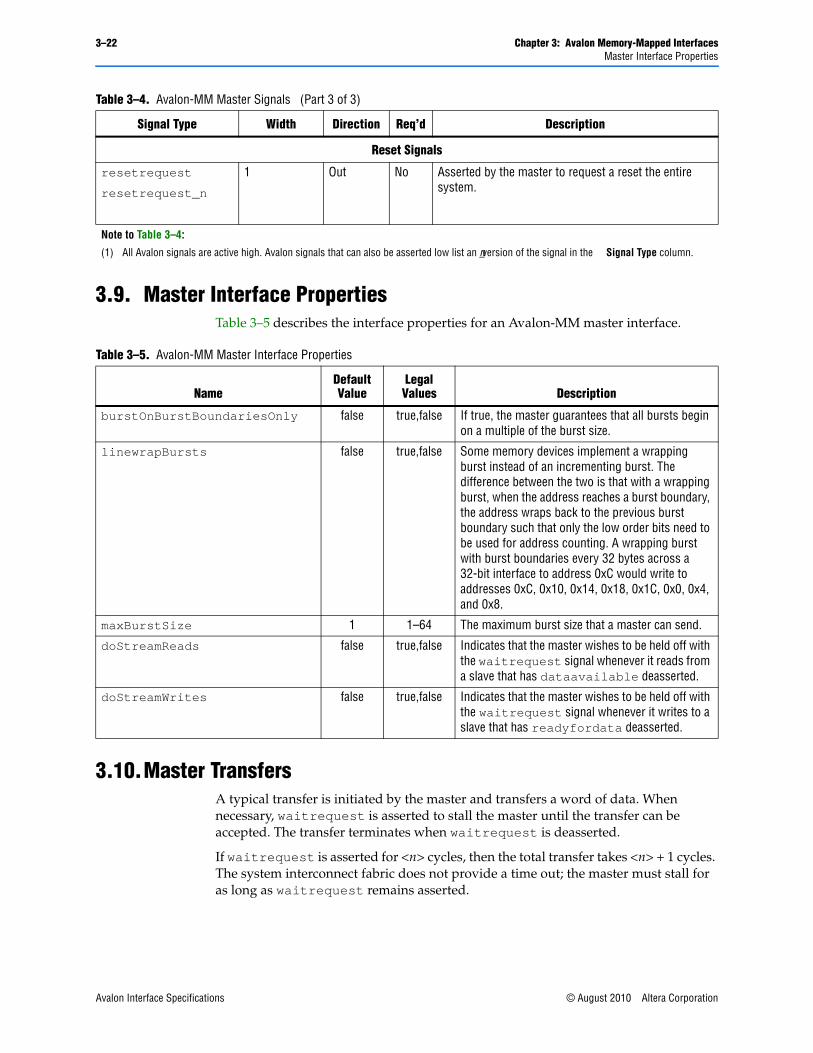
3.9. Master Interface PropertiesTable 3–5 describes the interface properties for an Avalon-MM master interface.
3.10.Master Transfers A typical transfer is initiated by the master and transfers a word of data. When necessary, waitrequest is asserted to stall the master until the transfer can be accepted. The transfer terminates when waitrequest is deasserted.
If waitrequest is asserted for <n> cycles, then the total transfer takes <n> + 1 cycles. The system interconnect fabric does not provide a time out; the master must stall for as long as waitrequest remains asserted.
Reset Signals
resetrequest
resetrequest_n
1 Out No Asserted by the master to request a reset the entire system.
Note to Table 3–4:
(1) All Avalon signals are active high. Avalon signals that can also be asserted low list an _n version of the signal in the Signal Type column.
Table 3–4. Avalon-MM Master Signals (Part 3 of 3)
Signal Type Width Direction Req’d Description
Table 3–5. Avalon-MM Master Interface Properties
NameDefault Value
Legal Values Description
burstOnBurstBoundariesOnly false true,false If true, the master guarantees that all bursts begin on a multiple of the burst size.
linewrapBursts false true,false Some memory devices implement a wrapping burst instead of an incrementing burst. The difference between the two is that with a wrapping burst, when the address reaches a burst boundary, the address wraps back to the previous burst boundary such that only the low order bits need to be used for address counting. A wrapping burst with burst boundaries every 32 bytes across a 32-bit interface to address 0xC would write to addresses 0xC, 0x10, 0x14, 0x18, 0x1C, 0x0, 0x4, and 0x8.
maxBurstSize 1 1–64 The maximum burst size that a master can send.
doStreamReads false true,false Indicates that the master wishes to be held off with the waitrequest signal whenever it reads from a slave that has dataavailable deasserted.
doStreamWrites false true,false Indicates that the master wishes to be held off with the waitrequest signal whenever it writes to a slave that has readyfordata deasserted.
Avalon Interface Specifications © August 2010 Altera Corporation
Chapter 3: Avalon Memory-Mapped Interfaces 3–23Master Transfers
A master can use the byteenable signal to indicate that it only requires data for specific bytes of readdata or to write specific bytes of writedata. If a master port does not have a byteenable signal, the transfer proceeds as if all byteenable are asserted.
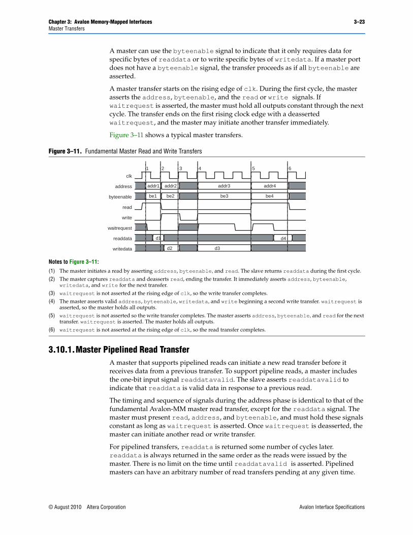
A master transfer starts on the rising edge of clk. During the first cycle, the master asserts the address, byteenable, and the read or write signals. If waitrequest is asserted, the master must hold all outputs constant through the next cycle. The transfer ends on the first rising clock edge with a deasserted waitrequest, and the master may initiate another transfer immediately.
Figure 3–11 shows a typical master transfers.
3.10.1.Master Pipelined Read TransferA master that supports pipelined reads can initiate a new read transfer before it receives data from a previous transfer. To support pipeline reads, a master includes the one-bit input signal readdatavalid. The slave asserts readdatavalid to indicate that readdata is valid data in response to a previous read.
The timing and sequence of signals during the address phase is identical to that of the fundamental Avalon-MM master read transfer, except for the readdata signal. The master must present read, address, and byteenable, and must hold these signals constant as long as waitrequest is asserted. Once waitrequest is deasserted, the master can initiate another read or write transfer.
For pipelined transfers, readdata is returned some number of cycles later. readdata is always returned in the same order as the reads were issued by the master. There is no limit on the time until readdatavalid is asserted. Pipelined masters can have an arbitrary number of read transfers pending at any given time.
Figure 3–11. Fundamental Master Read and Write Transfers
Notes to Figure 3–11:
(1) The master initiates a read by asserting address, byteenable, and read. The slave returns readdata during the first cycle.(2) The master captures readdata and deasserts read, ending the transfer. It immediately asserts address, byteenable,
writedata, and write for the next transfer.(3) waitrequest is not asserted at the rising edge of clk, so the write transfer completes. (4) The master asserts valid address, byteenable, writedata, and write beginning a second write transfer. waitrequest is
asserted, so the master holds all outputs.(5) waitrequest is not asserted so the write transfer completes. The master asserts address, byteenable, and read for the next
transfer. waitrequest is asserted. The master holds all outputs.(6) waitrequest is not asserted at the rising edge of clk, so the read transfer completes.
clk
address
byteenable
read
write
waitrequest
readdata
writedata
addr2addr1 addr3 addr4
be3be1 be2 be4
d3d2
d1 d4
1 2 3 4 5 6
© August 2010 Altera Corporation Avalon Interface Specifications
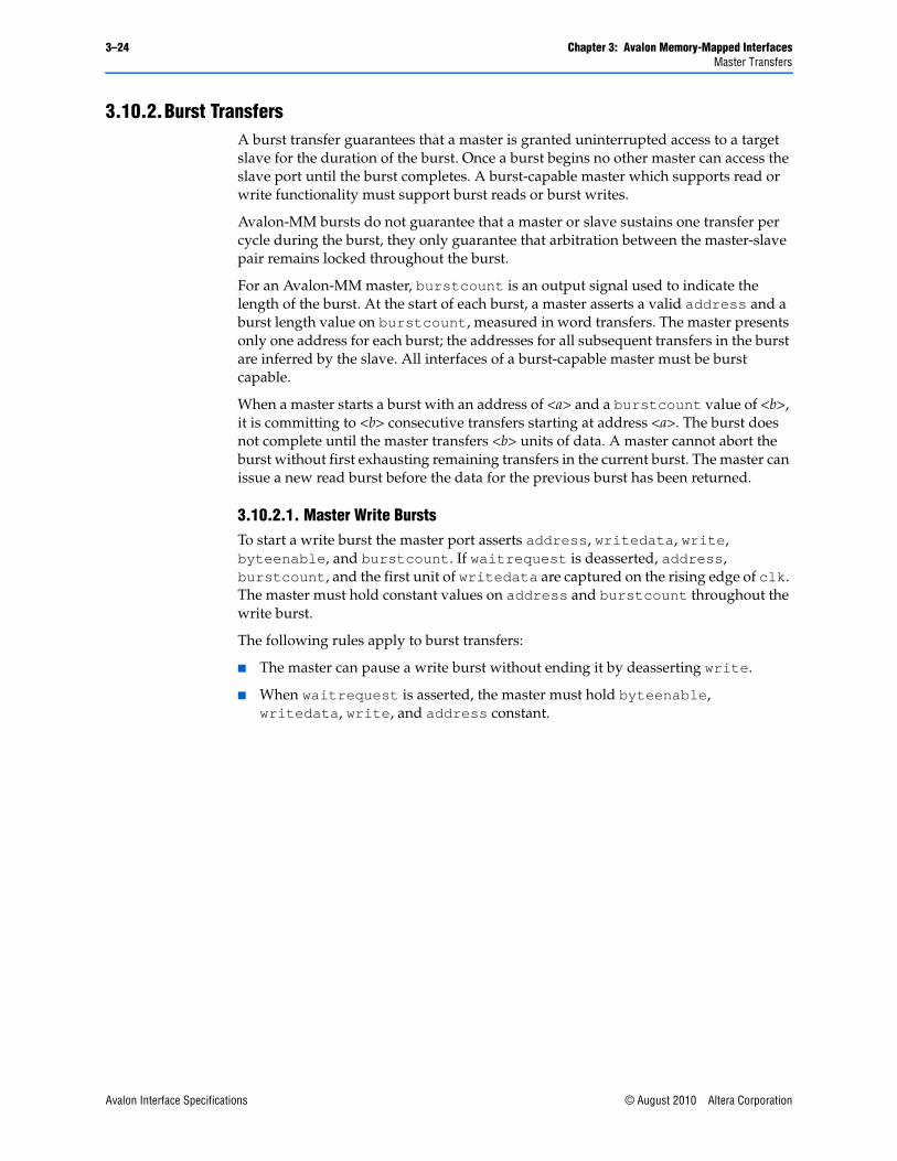
3–24 Chapter 3: Avalon Memory-Mapped InterfacesMaster Transfers
3.10.2.Burst TransfersA burst transfer guarantees that a master is granted uninterrupted access to a target slave for the duration of the burst. Once a burst begins no other master can access the slave port until the burst completes. A burst-capable master which supports read or write functionality must support burst reads or burst writes.
Avalon-MM bursts do not guarantee that a master or slave sustains one transfer per cycle during the burst, they only guarantee that arbitration between the master-slave pair remains locked throughout the burst.
For an Avalon-MM master, burstcount is an output signal used to indicate the length of the burst. At the start of each burst, a master asserts a valid address and a burst length value on burstcount, measured in word transfers. The master presents only one address for each burst; the addresses for all subsequent transfers in the burst are inferred by the slave. All interfaces of a burst-capable master must be burst capable.
When a master starts a burst with an address of <a> and a burstcount value of <b>, it is committing to <b> consecutive transfers starting at address <a>. The burst does not complete until the master transfers <b> units of data. A master cannot abort the burst without first exhausting remaining transfers in the current burst. The master can issue a new read burst before the data for the previous burst has been returned.
3.10.2.1. Master Write BurstsTo start a write burst the master port asserts address, writedata, write, byteenable, and burstcount. If waitrequest is deasserted, address, burstcount, and the first unit of writedata are captured on the rising edge of clk. The master must hold constant values on address and burstcount throughout the write burst.
The following rules apply to burst transfers:
■ The master can pause a write burst without ending it by deasserting write.
■ When waitrequest is asserted, the master must hold byteenable, writedata, write, and address constant.
Avalon Interface Specifications © August 2010 Altera Corporation
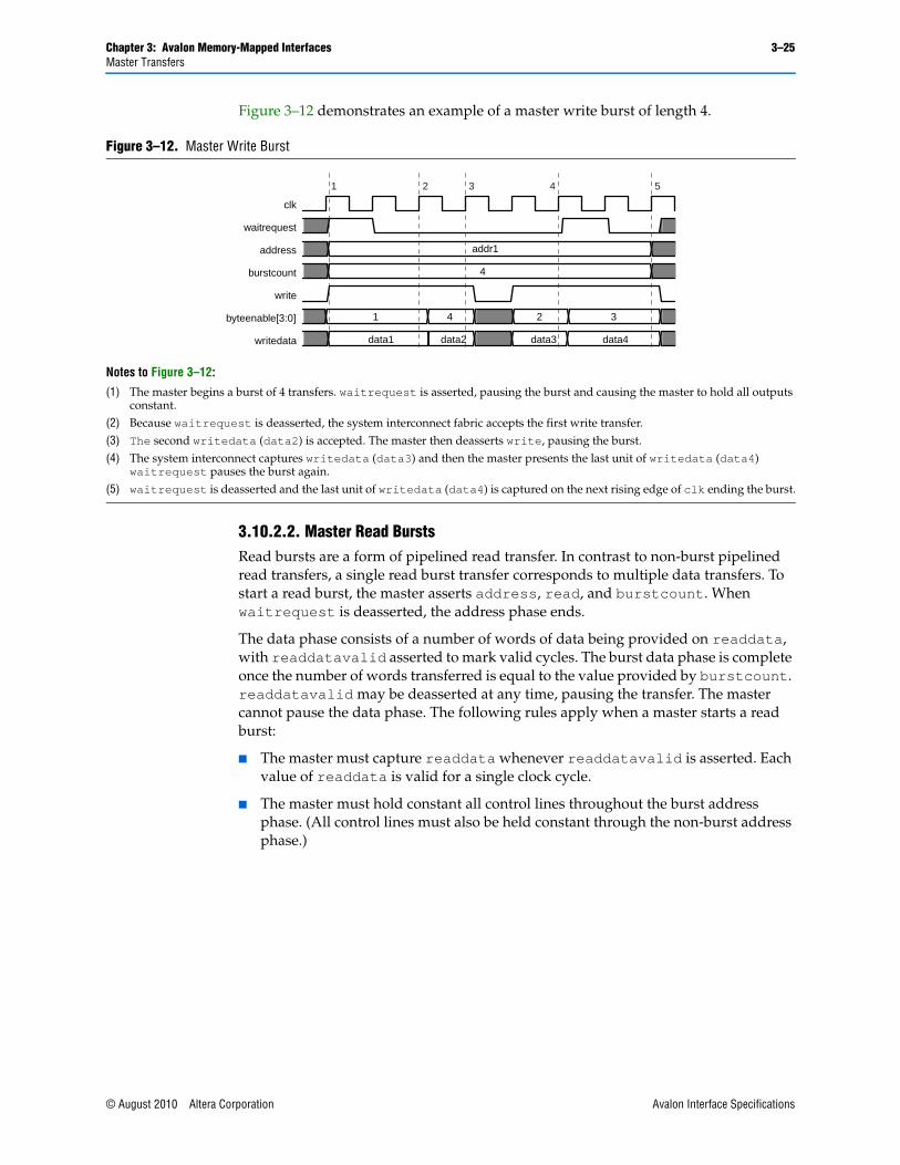
Chapter 3: Avalon Memory-Mapped Interfaces 3–25Master Transfers
Figure 3–12 demonstrates an example of a master write burst of length 4.
3.10.2.2. Master Read BurstsRead bursts are a form of pipelined read transfer. In contrast to non-burst pipelined read transfers, a single read burst transfer corresponds to multiple data transfers. To start a read burst, the master asserts address, read, and burstcount. When waitrequest is deasserted, the address phase ends.
The data phase consists of a number of words of data being provided on readdata, with readdatavalid asserted to mark valid cycles. The burst data phase is complete once the number of words transferred is equal to the value provided by burstcount. readdatavalid may be deasserted at any time, pausing the transfer. The master cannot pause the data phase. The following rules apply when a master starts a read burst:
■ The master must capture readdata whenever readdatavalid is asserted. Each value of readdata is valid for a single clock cycle.
■ The master must hold constant all control lines throughout the burst address phase. (All control lines must also be held constant through the non-burst address phase.)
Figure 3–12. Master Write Burst
Notes to Figure 3–12:
(1) The master begins a burst of 4 transfers. waitrequest is asserted, pausing the burst and causing the master to hold all outputs constant.
(2) Because waitrequest is deasserted, the system interconnect fabric accepts the first write transfer.(3) The second writedata (data2) is accepted. The master then deasserts write, pausing the burst. (4) The system interconnect captures writedata (data3) and then the master presents the last unit of writedata (data4)
waitrequest pauses the burst again.(5) waitrequest is deasserted and the last unit of writedata (data4) is captured on the next rising edge of clk ending the burst.
clk
waitrequest
address
burstcount
write
byteenable[3:0]
writedata
1 4
4
2 3
data1
addr1
data2 data3 data4
2 3 4 51
© August 2010 Altera Corporation Avalon Interface Specifications
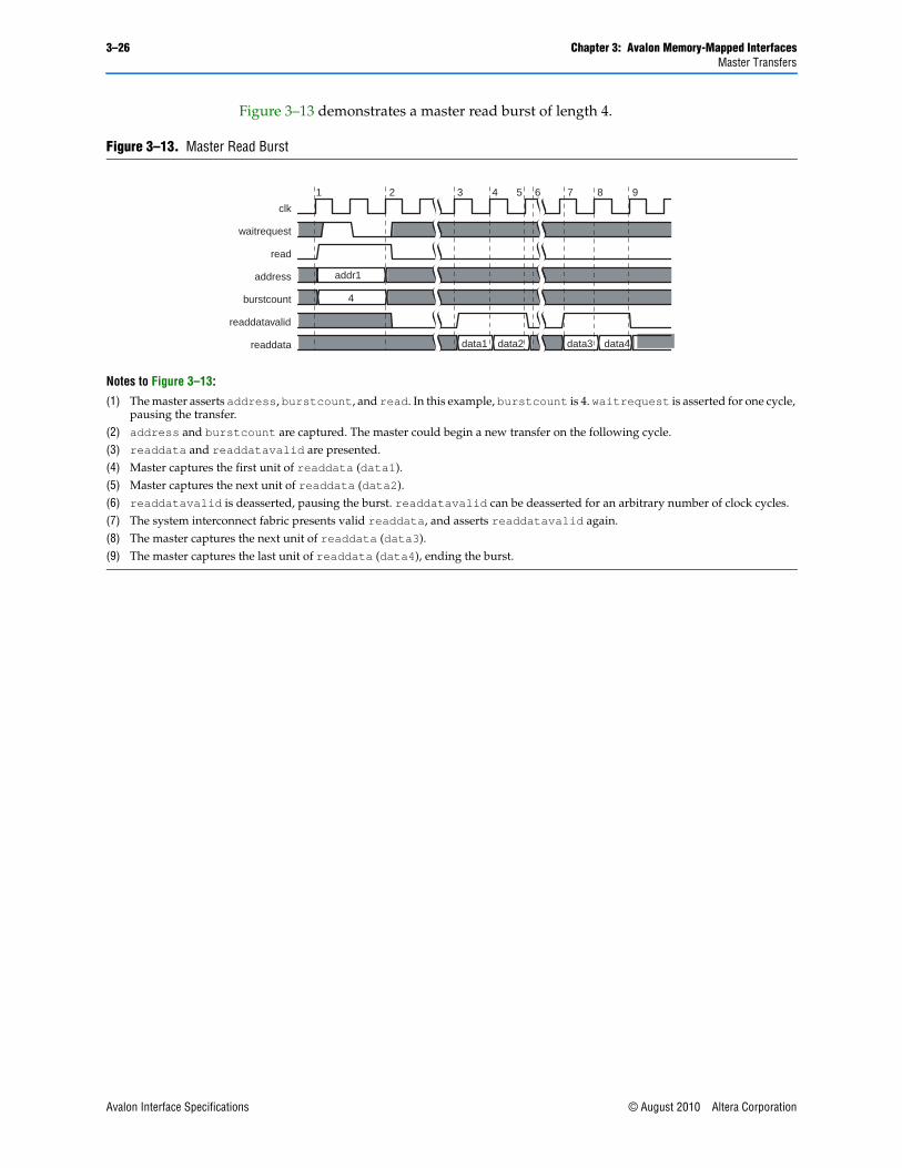
3–26 Chapter 3: Avalon Memory-Mapped InterfacesMaster Transfers
Figure 3–13 demonstrates a master read burst of length 4.
Figure 3–13. Master Read Burst
Notes to Figure 3–13:
(1) The master asserts address, burstcount, and read. In this example, burstcount is 4. waitrequest is asserted for one cycle, pausing the transfer.
(2) address and burstcount are captured. The master could begin a new transfer on the following cycle. (3) readdata and readdatavalid are presented.(4) Master captures the first unit of readdata (data1).(5) Master captures the next unit of readdata (data2).(6) readdatavalid is deasserted, pausing the burst. readdatavalid can be deasserted for an arbitrary number of clock cycles.(7) The system interconnect fabric presents valid readdata, and asserts readdatavalid again.(8) The master captures the next unit of readdata (data3).(9) The master captures the last unit of readdata (data4), ending the burst.
clk
waitrequest
read
address
burstcount
readdatavalid
readdata
addr1
4
data1 data2 data3 data4
2 3 5 76 8 91 4
Avalon Interface Specifications © August 2010 Altera Corporation
© August 2010 Altera Corporation
4. Interrupt Interfaces
Interrupt interfaces allow slave components to signal events to master components. For example, a DMA controller can interrupt a processor when it has completed a DMA transfer.
4.1. Interrupt SenderAn interrupt sender drives a single interrupt signal to an interrupt receiver. The timing of the irq signal must be synchronous to the rising edge of its associated clock, but has no relationship to any transfer on any other interface. irq must be asserted until the interrupt has been acknowledged on the associated Avalon-MM slave interface. An Avalon-MM slave can only include one interrupt sender.
The interrupt receiver typically determines how to respond to the event by reading an interrupt status register from an Avalon-MM slave interface. The mechanism used to acknowledge an interrupt is component specific.
4.1.1. Signal Types Table 4–1 lists the interrupt signal types.
4.1.2. Interrupt Sender PropertiesTable 4–2 lists the properties associated with interrupt senders.
4.2. Interrupt ReceiverAn interrupt receiver interface receives interrupts from interrupt sender interfaces. Components with an Avalon-MM master interface can include an interrupt receiver to detect interrupts asserted by slave components with interrupt sender interfaces. Interrupt receiver interfaces support two interrupt schemes:
Table 4–1. Interrupt Sender Signal Types
Signal Type Width Direction Required Description
irq
irq_n
1 Output Yes Interrupt Request. A slave asserts irq when it needs to be serviced.
Table 4–2. Interrupt Sender Properties
Property NameDefault Value Legal Values Description
associatedClockReset — Name of clock Interface on this component.
The name of the clock interface that this interrupt sender is synchronous to. The sender and receiver may have different values for this property.
associatedAddressablePoint — Name of Avalon-MM slave on this component.
The name of the Avalon-MM slave that provides access to the registers that should be accessed to service the interrupt.
Avalon Interface Specifications

4–2 Chapter 4: Interrupt InterfacesInterrupt Receiver
■ Individual requests—the interrupt receiver expects to see each interrupt request from each interrupt sender as a separate bit and is responsible for determining the relative priority of the interrupts,
■ Priority encoded—the interrupt receiver expects to see a single-bit irq signal and a six-bit interrupt number signal that indicates the number of the highest priority interrupt currently being asserted. Interrupt zero is the highest priority. There can only be one interrupt sender at each priority for a total of 64 senders in a system.
4.2.1. Interrupt Receiver PropertiesTable 4–3 lists the properties associated with interrupt receivers.
4.2.2. Signal TypesTable 4–4 lists the interrupt receiver signal types.
4.2.3. Interrupt Timing Figure 4–1 illustrates interrupt timing using both individual requests and priority encoding. In both cases, the Avalon-MM master services the priority 0 interrupt before the priority 1 interrupt.
Table 4–3. Interrupt Receiver Properties
Property Name Default Value Legal Values Description
irqScheme individualRequests individualRequestspriorityEncoded
Selects one of the two interrupt encoding schemes.
associatedAddressablePoint
—
Table 4–4. Interrupt Receiver Signal Types
Signal Type Width Direction Required Description
irq 1–32 Input Yes Indicates when one or more slave ports have requested an interrupt.
If irqScheme=individualRequests, irq is an <n>-bit vector, where each bit corresponds directly to one IRQ sender, with no inherent assumption of priority.
If irqScheme=priorityEncoded, irq is a one bit logical OR of all connected interrupt sender signals.
irqnumber 6 Input No Only used when irqScheme = priorityEncoded. irqnumber indicates the current highest priority interrupt.
Avalon Interface Specifications © August 2010 Altera Corporation
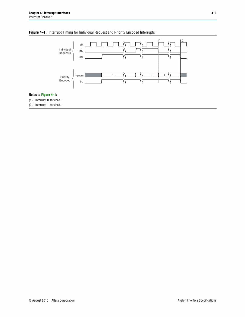
Chapter 4: Interrupt Interfaces 4–3Interrupt Receiver
Figure 4–1. Interrupt Timing for Individual Request and Priority Encoded Interrupts
Notes to Figure 4–1:
(1) Interrupt 0 serviced.(2) Interrupt 1 serviced.
clk
int0
int1
irqnum
irq
1 10 0
1 2
IndividualRequests
PriorityEncoded
© August 2010 Altera Corporation Avalon Interface Specifications

4–4 Chapter 4: Interrupt InterfacesInterrupt Receiver
Avalon Interface Specifications © August 2010 Altera Corporation

© August 2010 Altera Corporation
5. Avalon Memory-Mapped Tri-stateInterfaces
Avalon-MM tri-state slave interfaces allow Avalon-MM masters to drive off-chip devices. The interface allows data and address pins to be shared across multiple tri-state devices. Sharing is valuable in systems that have multiple external memory devices and limited pins. Figure 5–1 shows a typical example where multiple flash memories and an SRAM device are connected to the FPGA through a tri-state bridge. The Avalon-MM tri-state interface is required for these external devices to share pins.
5.1. Tri-state Slave Signal TypesTri-state slave ports use the bidirectional signal data rather than the separate, unidirectional signals readdata and writedata. Avalon-MM tri-state ports must also use the outputenable signal. Table 5–1 lists the Avalon-MM tri-state signal types.
Figure 5–1. Typical Use of Avalon-MM tri-state Interface
Avalon-MM System
Printed Circuit Board
Avalon-MMSlave
FlashMemory
Chip
TristateSlave Port
FlashMemory
Chip
TristateSlave Port
FlashMemory
Chip
TristateSlave Port
SRAMMemory
Chip
TristateSlave Port
TristateBridge
Shared Addr/Data Bus on PCB
System Interconnect Fabric
Avalon-MMMaster
Processor
Tristate Master
TristateSlave
TristateSlave
TristateSlave
TristateSlave
Avalon Interface Specifications
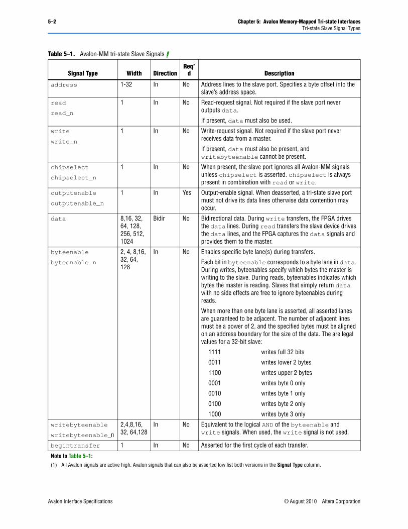
5–2 Chapter 5: Avalon Memory-Mapped Tri-state InterfacesTri-state Slave Signal Types
Table 5–1. Avalon-MM tri-state Slave Signals (1)
Signal Type Width DirectionReq’
d Description
address 1-32 In No Address lines to the slave port. Specifies a byte offset into the slave’s address space.
read
read_n
1 In No Read-request signal. Not required if the slave port never outputs data.
If present, data must also be used.
write
write_n
1 In No Write-request signal. Not required if the slave port never receives data from a master.
If present, data must also be present, and writebyteenable cannot be present.
chipselect
chipselect_n
1 In No When present, the slave port ignores all Avalon-MM signals unless chipselect is asserted. chipselect is always present in combination with read or write.
outputenable
outputenable_n
1 In Yes Output-enable signal. When deasserted, a tri-state slave port must not drive its data lines otherwise data contention may occur.
data 8,16, 32, 64, 128, 256, 512, 1024
Bidir No Bidirectional data. During write transfers, the FPGA drives the data lines. During read transfers the slave device drives the data lines, and the FPGA captures the data signals and provides them to the master.
byteenable
byteenable_n
2, 4, 8,16, 32, 64, 128
In No Enables specific byte lane(s) during transfers.
Each bit in byteenable corresponds to a byte lane in data. During writes, byteenables specify which bytes the master is writing to the slave. During reads, byteenables indicates which bytes the master is reading. Slaves that simply return data with no side effects are free to ignore byteenables during reads.
When more than one byte lane is asserted, all asserted lanes are guaranteed to be adjacent. The number of adjacent lines must be a power of 2, and the specified bytes must be aligned on an address boundary for the size of the data. The are legal values for a 32-bit slave:
1111 writes full 32 bits
0011 writes lower 2 bytes
1100 writes upper 2 bytes
0001 writes byte 0 only
0010 writes byte 1 only
0100 writes byte 2 only
1000 writes byte 3 only
writebyteenable
writebyteenable_n
2,4,8,16, 32, 64,128
In No Equivalent to the logical AND of the byteenable and write signals. When used, the write signal is not used.
begintransfer 1 In No Asserted for the first cycle of each transfer.
Note to Table 5–1:
(1) All Avalon signals are active high. Avalon signals that can also be asserted low list both versions in the Signal Type column.
Avalon Interface Specifications © August 2010 Altera Corporation
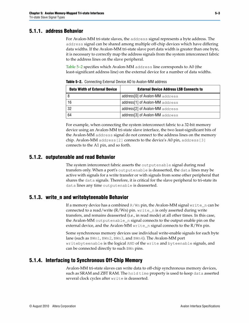
Chapter 5: Avalon Memory-Mapped Tri-state Interfaces 5–3Tri-state Slave Signal Types
5.1.1. address BehaviorFor Avalon-MM tri-state slaves, the address signal represents a byte address. The address signal can be shared among multiple off-chip devices which have differing data widths. If the Avalon-MM tri-state slave port data width is greater than one byte, it is necessary to correctly map the address signals from the system interconnect fabric to the address lines on the slave peripheral.
Table 5–2 specifies which Avalon-MM address line corresponds to A0 (the least-significant address line) on the external device for a number of data widths.
For example, when connecting the system interconnect fabric to a 32-bit memory device using an Avalon-MM tri-state slave interface, the two least-significant bits of the Avalon-MM address signal do not connect to the address lines on the memory chip. Avalon-MM address[2] connects to the device's A0 pin, address[3] connects to the A1 pin, and so forth.
5.1.2. outputenable and read BehaviorThe system interconnect fabric asserts the outputenable signal during read transfers only. When a port's outputenable is deasserted, the data lines may be active with signals for a write transfer or with signals from some other peripheral that shares the data signals. Therefore, it is critical for the slave peripheral to tri-state its data lines any time outputenable is deasserted.
5.1.3. write_n and writebyteenable BehaviorIf a memory device has a combined R/Wn pin, the Avalon-MM signal write_n can be connected to a read/write (R/Wn) pin. write_n is only asserted during write transfers, and remains deasserted (i.e., in read mode) at all other times. In this case, the Avalon-MM outputenable_n signal connects to the output enable pin on the external device, and the Avalon-MM write_n signal connects to the R/Wn pin.
Some synchronous memory devices use individual write-enable signals for each byte lane (such as BWn1, BWn2, BWn3, and BWn4). The Avalon-MM port writebyteenable is the logical AND of the write and byteenable signals, and can be connected directly to such BWn pins.
5.1.4. Interfacing to Synchronous Off-Chip MemoryAvalon-MM tri-state slaves can write data to off-chip synchronous memory devices, such as SRAM and ZBT RAM. The hold time property is used to keep data asserted several clock cycles after write is deasserted.
Table 5–2. Connecting External Device AO to Avalon-MM address
Data Width of External Device External Device Address LSB Connects to
8 address[0] of Avalon-MM address
16 address[1] of Avalon-MM address
32 address[2] of Avalon-MM address
64 address[3] of Avalon-MM address
© August 2010 Altera Corporation Avalon Interface Specifications

5–4 Chapter 5: Avalon Memory-Mapped Tri-state Interfacestri-state Slave Properties
Pipelined read transfers are supported if the component has fixed read latency. Pending pipelined read transfers are completed before initiating new write transfers to prevent possible signal contention. As a result, Avalon-MM tri-state slaves might not achieve the maximum possible throughput when performing back-to-back read-write transfer sequences.
Figure 5–2 shows an example of the connections between the system interconnect fabric and a synchronous, 32-bit memory. In this example, the Avalon-MM tri-state slave port is pipelined to accommodate the synchronous memory. The port uses separate read_n and outputenable_n signals. The chip in this example uses the writebyteenable signal for its four byte lanes. This chip has an 18-bit address. Note that the lower two bits of the 20-bit Avalon-MM address signal specify a byte address, and therefore do not connect to the chip's address lines.
5.2. tri-state Slave PropertiesTable 5–3 lists the properties of Avalon-MM tri-state slave interfaces. These include all the properties for slave interfaces defined in Chapter 3, Avalon Memory-Mapped Interfaces plus some additional properties to support off-chip devices.
Figure 5–2. Connection to Synchronous Memory Chip
clk
chipselect_n
outputenable_n
writebytenable_n[3..0]
data [31..0]
address[19..2]
Synchronous SRAM Chip
Ava
lon-
MM
Tris
tate
Sla
ve P
ortCLK
CEn
OEn
WBE
A[17..0]
D [31..0]
A,B,C,D
Avalon-MM System
VCC
GND
OtherPins
Rest of the
System
Sys
tem
Inte
rco
nn
ect
Fab
ric
read_nRn
Table 5–3. Avalon-MM tri-state Interface Properties (Part 1 of 2)
NameDefault Value Legal Values Description
readLatency 0 num_cycles Read latency for fixed-latency slaves. Refer to Figure 5–5 for an illustration of this property.
writeLatency 0 num_cycles Delay in cycles between acceptance of a write access and acceptance of valid writedata.
timingUnits cycles cycles, nanoseconds
Specifies the units for setupTime, holdTime, writeWaitTime and readWaitTime. Use cycles for synchronous devices and nanoseconds for asynchronous devices.
writeWaitTime 0 0–1000 Specifies additional time in units of timingUnits for write to be asserted.
Avalon Interface Specifications © August 2010 Altera Corporation
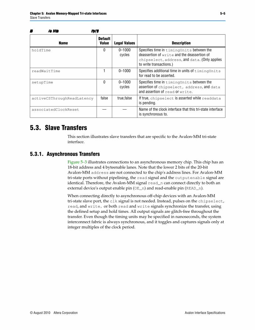
Chapter 5: Avalon Memory-Mapped Tri-state Interfaces 5–5Slave Transfers
5.3. Slave Transfers This section illustrates slave transfers that are specific to the Avalon-MM tri-state interface.
5.3.1. Asynchronous TransfersFigure 5–3 illustrates connections to an asynchronous memory chip. This chip has an 18-bit address and 4 byteenable lanes. Note that the lower 2 bits of the 20-bit Avalon-MM address are not connected to the chip's address lines. For Avalon-MM tri-state ports without pipelining, the read signal and the outputenable signal are identical. Therefore, the Avalon-MM signal read_n can connect directly to both an external device's output enable pin (OE_n) and read-enable pin (READ_n).
When connecting directly to asynchronous off-chip devices with an Avalon-MM tri-state slave port, the clk signal is not needed. Instead, pulses on the chipselect, read, and write, or both read and write signals synchronize the transfer, using the defined setup and hold times. All output signals are glitch-free throughout the transfer. Even though the timing units may be specified in nanoseconds, the system interconnect fabric is always synchronous, and it toggles and captures signals only at integer multiples of the clock period.
holdTime 0 0–1000 cycles
Specifies time in timingUnits between the deassertion of write and the deassertion of chipselect, address, and data. (Only applies to write transactions.)
readWaitTime 1 0–1000 Specifies additional time in units of timingUnits for read to be asserted.
setupTime 0 0–1000 cycles
Specifies time in timingUnits between the assertion of chipselect, address, and data and assertion of read or write.
activeCSThroughReadLatency false true,false If true, chipselect is asserted while readdata is pending.
associatedClockReset — — Name of the clock interface that this tri-state interface is synchronous to.
Table 5–3. Avalon-MM tri-state Interface Properties (Part 2 of 2)
NameDefault Value Legal Values Description
© August 2010 Altera Corporation Avalon Interface Specifications

5–6 Chapter 5: Avalon Memory-Mapped Tri-state InterfacesSlave Transfers
5.3.1.1. Setup TimeSome component, require address and chipselect signals to be stable for a period of time before the read signal is asserted. Avalon-MM transfers with setupTime accommodate such requirements.
A nonzero setupTime of means that after address and chipselect are asserted, there is a delay before read or write is asserted. The total number of cycles to complete the transfer depends on setup and wait time. For example, a slave port with 2 cycles of setup time and 3 cycles of wait time takes 6 cycles to complete the transfer: 2 setup cycles, plus 3 wait-state cycles, plus 1 cycle to capture data. Setup time is applied equally to both read and write transfers.
5.3.1.2. Hold TimeA nonzero holdTime of <n> means that, after write is deasserted, address, byteenable, writedata, and chipselect remain constant for <n> more cycles. Hold time only applies to write transactions. The total number of cycles to complete the transfer depends on setup, wait-state, and hold cycles. For example, a slave port with 2 cycles of setup time, 3 cycles of write wait time, 2 cycles of hold time takes 8 cycles to complete the transfer: 2 setup cycles plus 3 wait time cycles plus 2 hold cycles plus 1 cycle to capture data.
A slave port does not have to use both setup and hold times.
5.3.1.3. Example Read and Write Using Setup, Hold and Wait TimesFigure 5–4 shows Avalon-MM tri-state slave asynchronous read and write transfers, assuming a 50 MHz clock. This port uses the following Avalon-MM tri-state properties:
■ timingUnits is given in nanoseconds
■ setupTime is 50 ns (3 clocks at 50 MHz)
■ holdTime is 10 ns (1 clock at 50 MHz)
■ writeWaitTime is 30 ns (2 clocks at 50 MHz)
Figure 5–3. Connection to Asynchronous Memory Chip
chipselect_n
read_n
write_n
address[19..2]
data[31..0]
byteenable_n[3..0]
Asynchronous Memory Chip
Ava
lon-
MM
Tris
tate
Sla
ve P
ortCSn
OEn
R/Wn
A[17..0]
BEn[3..0]
D[31..0]
VCC
GND
OtherPins
Avalon-MM System
Rest of the
System
Sys
tem
Inte
rco
nn
ect
Fab
ric
Avalon Interface Specifications © August 2010 Altera Corporation

Chapter 5: Avalon Memory-Mapped Tri-state Interfaces 5–7Slave Transfers
■ readWaitTime is 30 ns (2 clocks at 50 MHz)
■ No pipelining
When the wait time is expressed in nanoseconds, the read or write period, as seen on the FPGA pins, is as long as the specified wait time, rounded up to the next clock period. Table 5–4 illustrates this point.
When the wait time is expressed as cycles, the number of cycles that the read or write signal is asserted is the value of waitTime plus one cycle for data capture.
Figure 5–4 shows the tri-state behavior for a single asynchronous memory. The data lines could be active at any time due to the transfer activity of other components sharing the data and address signals. clk is shown only to illustrate the relationship between signals and the system clock; it is not connected to the asynchronous device.
Table 5–4. Wait Times Expressed in Nanoseconds - 50 MHz Clock
Wait Time Number of Cycles
0 ns 1 cycle
10 ns 1 cycle
20 ns 1 cycle
21 ns 2 cycles
Table 5–5. Wait Times Expressed in Cycles
Wait Time Number of Cycles
0 cycles 1 clock period
1 cycle 2 clock periods
2 cycles 3 clock periods
© August 2010 Altera Corporation Avalon Interface Specifications
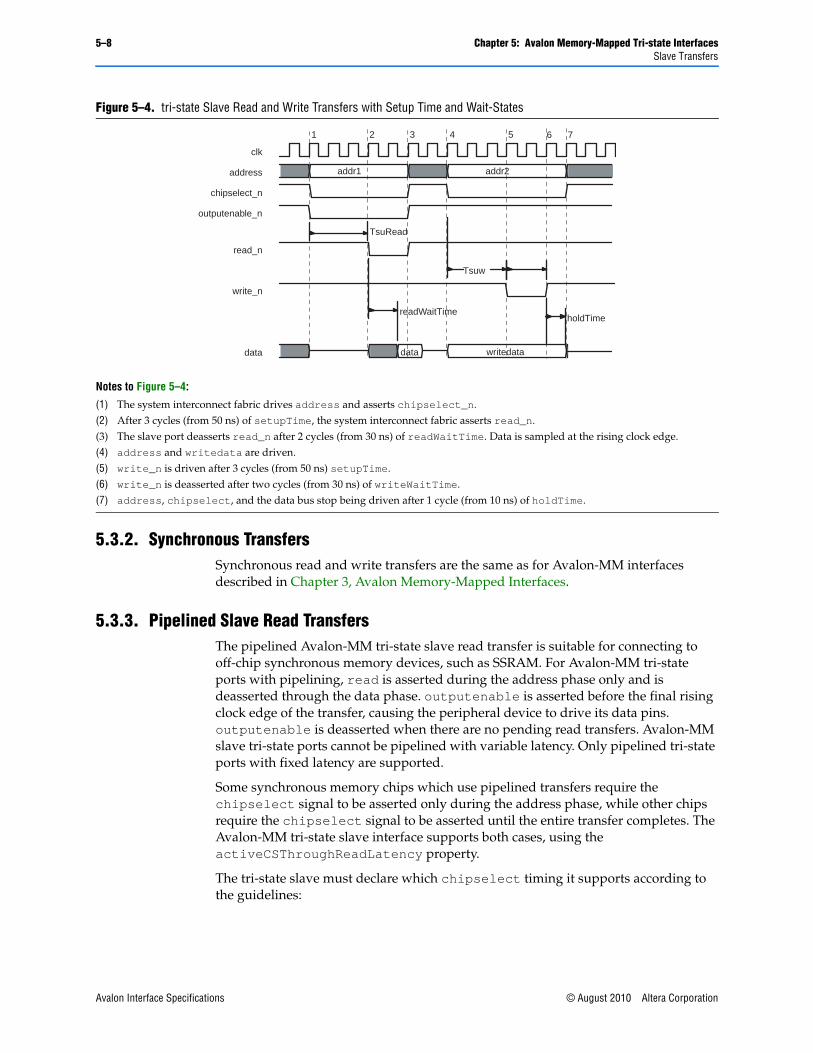
5–8 Chapter 5: Avalon Memory-Mapped Tri-state InterfacesSlave Transfers
5.3.2. Synchronous TransfersSynchronous read and write transfers are the same as for Avalon-MM interfaces described in Chapter 3, Avalon Memory-Mapped Interfaces.
5.3.3. Pipelined Slave Read TransfersThe pipelined Avalon-MM tri-state slave read transfer is suitable for connecting to off-chip synchronous memory devices, such as SSRAM. For Avalon-MM tri-state ports with pipelining, read is asserted during the address phase only and is deasserted through the data phase. outputenable is asserted before the final rising clock edge of the transfer, causing the peripheral device to drive its data pins. outputenable is deasserted when there are no pending read transfers. Avalon-MM slave tri-state ports cannot be pipelined with variable latency. Only pipelined tri-state ports with fixed latency are supported.
Some synchronous memory chips which use pipelined transfers require the chipselect signal to be asserted only during the address phase, while other chips require the chipselect signal to be asserted until the entire transfer completes. The Avalon-MM tri-state slave interface supports both cases, using the activeCSThroughReadLatency property.
The tri-state slave must declare which chipselect timing it supports according to the guidelines:
Figure 5–4. tri-state Slave Read and Write Transfers with Setup Time and Wait-States
Notes to Figure 5–4:
(1) The system interconnect fabric drives address and asserts chipselect_n.(2) After 3 cycles (from 50 ns) of setupTime, the system interconnect fabric asserts read_n.(3) The slave port deasserts read_n after 2 cycles (from 30 ns) of readWaitTime. Data is sampled at the rising clock edge.(4) address and writedata are driven.(5) write_n is driven after 3 cycles (from 50 ns) setupTime.(6) write_n is deasserted after two cycles (from 30 ns) of writeWaitTime.(7) address, chipselect, and the data bus stop being driven after 1 cycle (from 10 ns) of holdTime.
clk
address
chipselect_n
outputenable_n
read_n
write_n
data
addr1 addr2
data writedata
Tsuw
readWaitTime
TsuRead
2 3 4 5 6 71
holdTime
Avalon Interface Specifications © August 2010 Altera Corporation

Chapter 5: Avalon Memory-Mapped Tri-state Interfaces 5–9Slave Transfers
■ When a tri-state slave declares activeCSThroughReadLatency property to be true, chipselect is asserted throughout both the address and data phases of the read transfer. In this case, chipselect mirrors outputenable.
■ When a port does not use the activeCSThroughReadLatency property, chipselect is only asserted during the address phase. In this case, chipselect mirrors read.
Figure 5–5 shows a pipelined Avalon-MM tri-state slave read transfer. This port uses the Avalon-MM properties:
■ readLatency is set to 2
■ writeLatency is set to 2
■ activeCSThroughReadLatency is shown for both the true and false settings
The diagram shows the behavior for one component. However, the data lines could be active at any time due to the transfer activity of a different peripheral sharing the data and address signals.
Figure 5–5. Pipelined tri-state Slave Read Transfers
Notes to Figure 5–5:
(1) chipselect_n, addr1, and read_n are asserted, initiating a read transfer. At this time outputenable_n is also asserted, so the slave device can drive the data lines at any time.
(2) The slave device captures addr1 and read_n on this rising edge of clk. The data phase begins, and the slave produces valid data two clock cycles later.
(3) read_n is deasserted on this rising edge of clk, so the master is not issuing a new read command. When activeCSThroughReadLatency is false, chipselect_n is deasserted, and the tri-state slave must not drive the data bus.
(4) data1 is captured at this rising edge of clk. chipselect_n, addr2, and read_n are asserted initiating transfer 2.(5) The system interconnect fabric asserts chipselect_n, addr3, and read_n at this rising edge of clk, initiating transfer 3.
Because outputenable_n is asserted, the slave device could drive the data lines. (6) The system interconnect fabric captures data2 at the rising edge of clk. read_n is deasserted, ending the sequence of read
transfers. If activeCSThroughReadLatency is asserted chipselect remains asserted until all pending read transfers have completed, otherwise it is deasserted.
(7) The system interconnect fabric captures data3. (8) The system interconnect fabric captures data4. There are no more pending transfers so chipselect and outputenable_n are
deasserted, forcing the slave peripheral to stop driving its data lines.
clk
address
chipselect_n
chipselect_n
read_n
write_n
data
(activeCSThroughReadLatency=true)
(activeCSThroughReadLatency=false)
addr1 addr2 addr3 addr4
data1 data2 data3 data4
2 3 4 5 6 7 81
© August 2010 Altera Corporation Avalon Interface Specifications

5–10 Chapter 5: Avalon Memory-Mapped Tri-state InterfacesMaster Transfers
5.4. Master TransfersAvalon-MM tri-state slaves are mastered by Avalon-MM masters via a tri-state bridge. Avalon-MM tri-state masters are not supported on other components. For more information on Avalon-MM master refer to Chapter 3, Avalon Memory-Mapped Interfaces.
Avalon Interface Specifications © August 2010 Altera Corporation
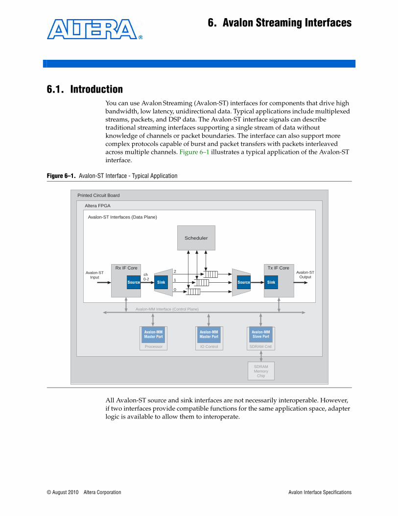
© August 2010 Altera Corporation
6. Avalon Streaming Interfaces
6.1. IntroductionYou can use Avalon Streaming (Avalon-ST) interfaces for components that drive high bandwidth, low latency, unidirectional data. Typical applications include multiplexed streams, packets, and DSP data. The Avalon-ST interface signals can describe traditional streaming interfaces supporting a single stream of data without knowledge of channels or packet boundaries. The interface can also support more complex protocols capable of burst and packet transfers with packets interleaved across multiple channels. Figure 6–1 illustrates a typical application of the Avalon-ST interface.
All Avalon-ST source and sink interfaces are not necessarily interoperable. However, if two interfaces provide compatible functions for the same application space, adapter logic is available to allow them to interoperate.
Figure 6–1. Avalon-ST Interface - Typical Application
SDRAMMemory
Chip
Avalon-MMMaster Port
Processor
Avalon-MM Interface (Control Plane)
Avalon-MMMaster Port
IO Control
Avalon-MMSlave Port
SDRAM Cntl
Source Sink SinkSource
ch 0-2
2
1
0
Scheduler
Tx IF CoreRx IF CoreAvalon-ST
InputAvalon-ST
Output
Avalon-ST Interfaces (Data Plane)
Altera FPGA
Printed Circuit Board
Avalon Interface Specifications
6–2 Chapter 6: Avalon Streaming InterfacesIntroduction
6.1.1. FeaturesSome of the prominent features of the Avalon-ST interface are:
■ Low latency, high throughput point-to-point data transfer
■ Multiple channel support with flexible packet interleaving
■ Sideband signaling of channel, error, and start and end of packet delineation
■ Support for data bursting
■ Automatic interface adaptation
6.1.2. Terms and ConceptsThis section defines terms and concepts used in the Avalon-ST interface protocol.
■ Avalon Streaming System—An Avalon Streaming system is a system that contains one or more Avalon-ST connections that transfer data from a source interface to a sink interface. The system shown in Figure 6–1 consists of Avalon-ST interfaces to transfer data from the system input to output and Avalon-MM control and status register interfaces to allow software control.
■ Avalon Streaming Components—A typical system using Avalon-ST interfaces combines multiple functional modules, called components. The system designer configures the components and connects them together to implement a system.
■ Source and Sink Interfaces and Connections—When two components are connected, the data flows from the source interface to the sink interface. The combination of a source interface connected to a sink interface is referred to as a connection.
■ Backpressure—Backpressure is a mechanism by which a sink can signal to a source to stop sending data. The sink typically uses backpressure to stop the flow of data when its FIFOs are full or when there is congestion on its output port. Support for backpressure is optional.
■ Transfers and Ready Cycles—A transfer is an operation that results in data and control propagation from a source interface to a sink interface. For data interfaces, a ready cycle is a cycle during which the sink can accept a transfer.
■ Symbol—A symbol is the smallest unit of data. For most packet interfaces, a symbol is a byte. One or more symbols make up the single unit of data transferred in a cycle.
■ Channel—A channel is a physical or logical path or link through which information passes between two ports.
■ Packet—A packet is an aggregation of data and control signals that is transmitted together. A packet may contain a header to help routers and other network devices direct the packet to the correct destination. The packet format is defined by the application, not this specification. Avalon-ST packets can be variable in length and can be interleaved across a connection. With an Avalon-ST interfaces, the use of packets is optional.
Avalon Interface Specifications © August 2010 Altera Corporation

Chapter 6: Avalon Streaming Interfaces 6–3Avalon-ST Interface Signals
6.2. Avalon-ST Interface SignalsEach signal in an Avalon-ST source or sink interface corresponds to one Avalon-ST signal type; an Avalon-ST interface may contain only one instance of each signal type. All Avalon-ST signal types apply to both sources and sinks and have the same meaning for both.
Table 6–1 lists the signal types that comprise an Avalon-ST data interface.
Table 6–1. Avalon-ST Interface Signals
Signal Type Width Direction Required Description
Fundamental Signals
ready 1 Sink → Source
No Asserted high to indicate that the sink can accept data. On interfaces supporting flow control, ready is asserted by the sink on cycle <n> to mark cycle <n + readyLatency> as a ready cycle, during which the source may assert valid and transfer data.
Sources without a ready input cannot be backpressured, and sinks without a ready output never need to backpressure.
valid 1 Source → Sink
No Asserted by the source to qualify all other source to sink signals. On ready cycles where valid is asserted, the data bus and other source to sink signals are sampled by the sink, and on other cycles are ignored.
Sources without a valid output implicitly provide valid data on every cycle that they are not being backpressured, and sinks without a valid input expect valid data on every cycle that they are not backpressuring.
data 1–256 Source → Sink
No The data signal from the source to the sink, typically carries the bulk of the information being transferred.
The contents and format of the data signal is further defined by parameters.
channel 0–127 Source → Sink
No The channel number for data being transferred on the current cycle.
If an interface supports the channel signal, it must also define the maxChannel parameter.
error 1–255 Source → Sink
No A bit mask used to mark errors affecting the data being transferred in the current cycle. A single bit in error is used for each of the errors recognized by the component, as defined by the errorDescriptor property.
Packet Transfer Signals
startofpacket 1 Source → Sink
No Asserted by the source to mark the beginning of a packet.
endofpacket 1 Source → Sink
No Asserted by the source to mark the end of a packet.
empty 0–8 Source → Sink
No Indicates the number of symbols that are empty during cycles that contain the end of a packet. The empty signal is not used on interfaces where there is one symbol per beat. If endofpacket is not asserted, this signal is not interpreted.
© August 2010 Altera Corporation Avalon Interface Specifications
6–4 Chapter 6: Avalon Streaming InterfacesAvalon-ST Interface Properties
6.2.1. Signal PolarityAll signal types listed in Table 6–1 are active high.
6.2.2. Signal Sequencing and TimingThis section describes issues related to timing and sequencing of Avalon-ST signals.
6.2.2.1. Synchronous InterfaceAll transfers of an Avalon-ST connection occur synchronous to the rising edge of the associated clock signal. All outputs from a source interface to a sink interface, including the data, channel, and error signals, must be registered on the rising edge of clock. Inputs to a sink interface do not have to be registered. Registering signals at the source provides for high frequency operation while eliminating back-to-back registers with no intervening logic.
6.2.2.2. Clock EnablesAvalon-ST components typically do not include a clock enable input, because the Avalon-ST signaling itself is sufficient to determine the cycles that a component should and should not be enabled. Avalon-ST compliant components may have a clock enable input for their internal logic, but they must take care to ensure that the timing of the interface control signals still adheres to the protocol.
6.3. Avalon-ST Interface PropertiesTable 6–2 lists the properties that characterize an Avalon-ST interface.
6.4. Typical Data TransfersThis section defines the transfer of data from a source interface to a sink interface. In all cases, the data source and the data sink must comply with the specification. It is not the responsibility of the data sink to detect source protocol errors.
Table 6–2. Avalon-ST Interface Properties
Property NameDefault Value Legal Values Description
dataBitsPerSymbol 8 1–512 Defines the number of bits per symbol. For example, byte-oriented interfaces have 8-bit symbols. This value is not restricted to be a power of 2.
readyLatency 0 0–8 Defines the relationship between assertion/deassertion of the ready signal, and cycles which are considered to be ready for data transfer, separately for each interface.
maxChannel 0 0–255 The maximum number of channels that a data interface can support.
errorDescriptor 0 list of strings A list of words that describe the error associated with each bit of the error signal. The length of the list must be the same as the number of bits in the error signal, and the first word in the list applies to the highest order bit. For example, “crc, overflow" means that bit[1] of error indicates a CRC error, and bit[0] indicates an overflow error.
Avalon Interface Specifications © August 2010 Altera Corporation

Chapter 6: Avalon Streaming Interfaces 6–5Typical Data Transfers
6.4.1. Signal DetailsThis section describes the basic Avalon-ST protocol that all data transfers must follow. It also highlights the flexibility you have in choosing Avalon-ST signals to meet the needs of a particular component and makes recommendations about the signals that should be used.
Figure 6–1 shows the signals that are typically included in an Avalon-ST interface. As this figure indicates, a typical Avalon-ST source interface drives the valid, data, error, and channel signals to the sink. The sink can apply backpressure using the ready signal.
The following paragraphs provide more details about these signals.
■ ready—On interfaces supporting backpressure, the sink asserts ready to mark ready cycles, cycles where transfers may take place. Data interfaces that support backpressure must define the readyLatency parameter so that if ready is asserted on cycle <n>, cycle <n + readyLatency> is considered a ready cycle.
■ valid—The valid signal qualifies valid data on any cycle where data is being transferred from the source to the sink. On each active cycle the data signal and other source to sink signals are sampled by the sink.
■ data—The data signal typically carries the bulk of the information being transferred from the source to the sink, and consists of one or more symbols being transferred on every clock cycle. The dataBitsPerSymbol parameter defines how the data signal is divided into symbols.
■ error—Errors are signaled with the error signal, where each bit in error corresponds to a possible error condition. A value of 0 on any cycle indicates the data on that cycle is error-free. The action that a component takes when an error is detected is not defined by this specification.
■ channel—The optional channel signal is driven by the source to indicate the channel to which the data belongs. The meaning of channel for a given interface depends on the application: some applications use channel as a port number indication, while other applications use channel as a page number or timeslot indication. When the channel signal is used, all of the data transferred in each active cycle belongs to the same channel. The source may change to a different channel on successive active cycles.
An interface that uses the channel signal must define the maxChannel parameter to indicate the maximum channel number. If the number of channels that the interface supports varies while the component is operating, maxChannel is the maximum channel number that the interface can support.
Figure 6–2. Typical Avalon-ST Interface Signals
channel<max_channel>
valid
data
error
ready
Data SinkData Source
© August 2010 Altera Corporation Avalon Interface Specifications
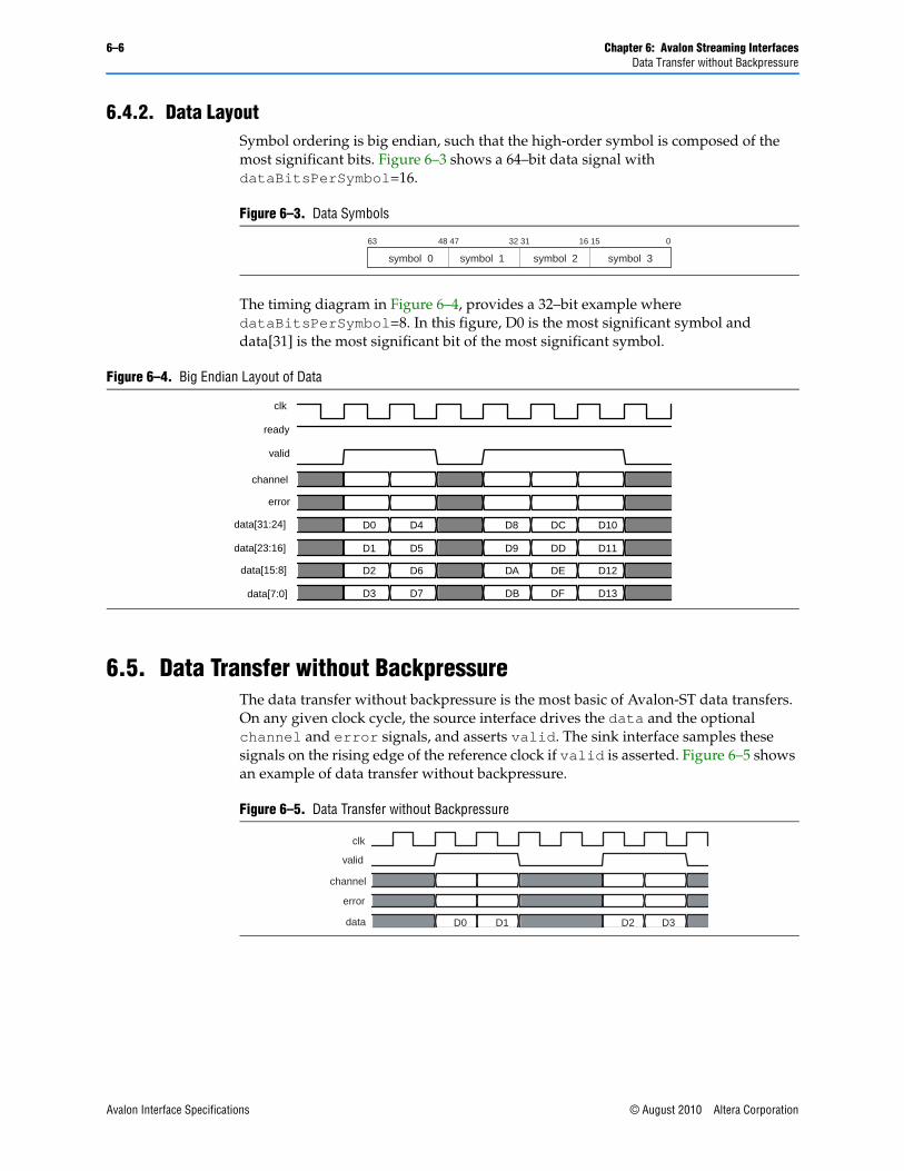
6–6 Chapter 6: Avalon Streaming InterfacesData Transfer without Backpressure
6.4.2. Data LayoutSymbol ordering is big endian, such that the high-order symbol is composed of the most significant bits. Figure 6–3 shows a 64–bit data signal with dataBitsPerSymbol=16.
The timing diagram in Figure 6–4, provides a 32–bit example where dataBitsPerSymbol=8. In this figure, D0 is the most significant symbol and data[31] is the most significant bit of the most significant symbol.
6.5. Data Transfer without BackpressureThe data transfer without backpressure is the most basic of Avalon-ST data transfers. On any given clock cycle, the source interface drives the data and the optional channel and error signals, and asserts valid. The sink interface samples these signals on the rising edge of the reference clock if valid is asserted. Figure 6–5 shows an example of data transfer without backpressure.
Figure 6–3. Data Symbols
symbol 0 symbol 3symbol 2symbol 1
63 48 47 32 31 16 15 0
Figure 6–4. Big Endian Layout of Data
clk
ready
valid
channel
error
data[31:24]
data[23:16]
data[15:8]
data[7:0]
D0 D4 D8
D1
D2
D3
D5
D6
D7
D9
DA
DD
DC
DE
DF
D11
D12
DB
D10
D13
Figure 6–5. Data Transfer without Backpressure
clk
valid
channel
error
data D1 D2 D3D0
Avalon Interface Specifications © August 2010 Altera Corporation
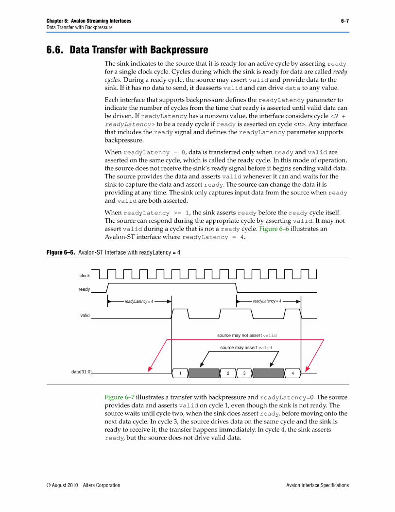
Chapter 6: Avalon Streaming Interfaces 6–7Data Transfer with Backpressure
6.6. Data Transfer with BackpressureThe sink indicates to the source that it is ready for an active cycle by asserting ready for a single clock cycle. Cycles during which the sink is ready for data are called ready cycles. During a ready cycle, the source may assert valid and provide data to the sink. If it has no data to send, it deasserts valid and can drive data to any value.
Each interface that supports backpressure defines the readyLatency parameter to indicate the number of cycles from the time that ready is asserted until valid data can be driven. If readyLatency has a nonzero value, the interface considers cycle <N + readyLatency> to be a ready cycle if ready is asserted on cycle <n>. Any interface that includes the ready signal and defines the readyLatency parameter supports backpressure.
When readyLatency = 0, data is transferred only when ready and valid are asserted on the same cycle, which is called the ready cycle. In this mode of operation, the source does not receive the sink’s ready signal before it begins sending valid data. The source provides the data and asserts valid whenever it can and waits for the sink to capture the data and assert ready. The source can change the data it is providing at any time. The sink only captures input data from the source when ready and valid are both asserted.
When readyLatency >= 1, the sink asserts ready before the ready cycle itself. The source can respond during the appropriate cycle by asserting valid. It may not assert valid during a cycle that is not a ready cycle. Figure 6–6 illustrates an Avalon-ST interface where readyLatency = 4.
Figure 6–7 illustrates a transfer with backpressure and readyLatency=0. The source provides data and asserts valid on cycle 1, even though the sink is not ready. The source waits until cycle two, when the sink does assert ready, before moving onto the next data cycle. In cycle 3, the source drives data on the same cycle and the sink is ready to receive it; the transfer happens immediately. In cycle 4, the sink asserts ready, but the source does not drive valid data.
Figure 6–6. Avalon-ST Interface with readyLatency = 4
clock
ready
valid
data[31:0]
readyLatency = 4 readyLatency = 4
1 2 3 4
source may not assert valid
source may assert valid
© August 2010 Altera Corporation Avalon Interface Specifications

6–8 Chapter 6: Avalon Streaming InterfacesPacket Data Transfers
Figure 6–8 and Figure 6–9 show data transfers with readyLatency=1 and readyLatency=2, respectively. In both these cases, ready is asserted before the ready cycle, and the source responds 1 or 2 cycles later by providing data and asserting valid. When readyLatency is not 0, the source must deassert valid on non-ready cycles. The sink captures data on any cycle where valid is asserted, regardless of the value of ready on that cycle.
6.7. Packet Data TransfersThe packet transfer property adds support for transferring packets from a source interface to a sink interface. Three additional signals are defined to implement the packet transfer. Both the source and sink interfaces must include these additional signals to support packets. No automatic adaptation to create connections between source and sink interfaces with and without packet support.
Figure 6–7. Transfer with Backpressure, readyLatency=0
Figure 6–8. Transfer with Backpressure, readyLatency=1
Figure 6–9. Transfer with Backpressure, readyLatency=2
clk
ready
valid
channel
error
data
0 1 2 3 5 6 7 84
D0 D1 D2 D3
clk
ready
valid
channel
error
data D0 D1 D2 D3 D4 D5
clk
ready
valid
channel
error
data D0 D1 D2 D3
Avalon Interface Specifications © August 2010 Altera Corporation

Chapter 6: Avalon Streaming Interfaces 6–9Packet Data Transfers
6.7.1. Signal DetailsThe following paragraphs provide more details about these three signals.
■ startofpacket—The startofpacket signal is required by all interfaces supporting packet transfers and marks the active cycle containing the start of the packet. This signal is only interpreted when valid is asserted.
■ endofpacket—The endofpacket signal is required by all interfaces supporting packet transfer and marks the active cycle containing the end of the packet. This signal is only interpreted when valid is asserted. startofpacket and endofpacket can be asserted in the same cycle. No idle cycles are required between packets, so that the startofpacket signal can follow immediately after the previous endofpacket signal.
■ empty—The optional empty signal indicates the number of symbols that are empty during the cycles that mark the end of a packet. The sink only checks the value of the empty during active cycles that have endofpacket asserted. The empty symbols are always the last symbols in data, those carried by the low-order bits. The empty signal is required on all packet interfaces whose data signal carries more than one symbol of data and have a variable length packet format. The size of the empty signal in bits is log2(<symbols per cycle>).
6.7.2. Protocol DetailsPacket data transfer follows the same protocol as the typical data transfer described in “Typical Data Transfers” on page 6–4, with the addition of the startofpacket, endofpacket, and empty.
Figure 6–11 illustrates the transfer of a 17-byte packet from a source interface to a sink interface, where readyLatency=0. Data transfer occurs on cycles 1, 2, 4, 5, and 6, when both ready and valid are asserted. During cycle 1, startofpacket is asserted, and the first 4 bytes of packet are transferred. During cycle 6, endofpacket is asserted, and empty has a value of 3, indicating that this is the end of the packet and that 3 of the 4 symbols are empty. In cycle 6, the high-order byte, data[31:24] drives valid data because Avalon-ST is big-endian.
Figure 6–10. Avalon-ST Packet Interface Signals
channel<max_channel>
valid
data
error
ready
Data Source Data Sink
empty
startofpacket
endofpacket
© August 2010 Altera Corporation Avalon Interface Specifications
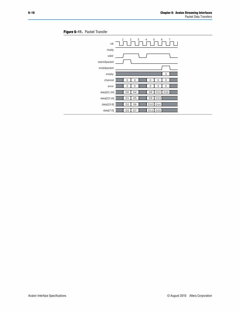
6–10 Chapter 6: Avalon Streaming InterfacesPacket Data Transfers
Figure 6–11. Packet Transfer
clk
ready
valid
startofpacket
endofpacket
empty
channel
error
data[31:24]
data[23:16]
data[15:8]
data[7:0]
0 0 0 0 0
0 0 0 0 0
D0 D4 D8 D12 D16
D1 D5 D9 D13
D2 D6 D10 D14
D3 D7 D11 D15
3
1 2 3 4 5 6 7
Avalon Interface Specifications © August 2010 Altera Corporation
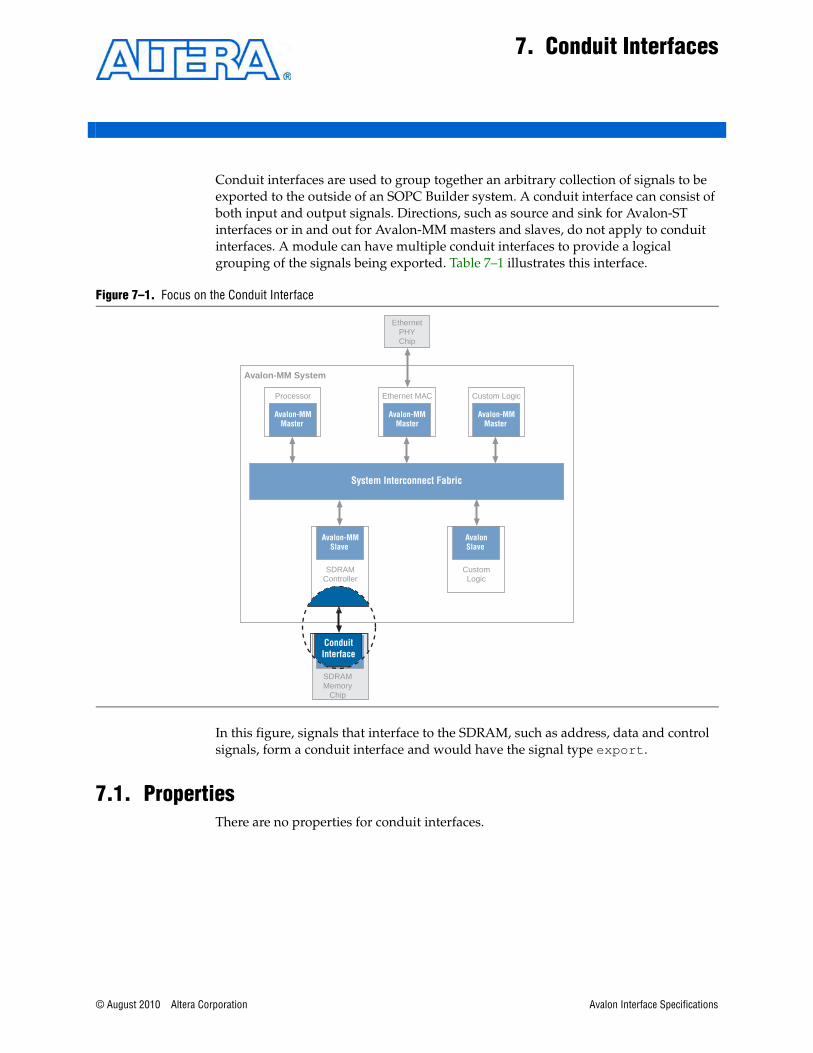
© August 2010 Altera Corporation
7. Conduit Interfaces
Conduit interfaces are used to group together an arbitrary collection of signals to be exported to the outside of an SOPC Builder system. A conduit interface can consist of both input and output signals. Directions, such as source and sink for Avalon-ST interfaces or in and out for Avalon-MM masters and slaves, do not apply to conduit interfaces. A module can have multiple conduit interfaces to provide a logical grouping of the signals being exported. Table 7–1 illustrates this interface.
In this figure, signals that interface to the SDRAM, such as address, data and control signals, form a conduit interface and would have the signal type export.
7.1. PropertiesThere are no properties for conduit interfaces.
Figure 7–1. Focus on the Conduit Interface
Avalon-MM System
System Interconnect Fabric
EthernetPHYChip
AvalonSlave
Avalon-MMSlave
SDRAMMemory
Chip
Avalon-MMMaster
Processor
Avalon-MMMaster
Avalon-MMMaster
Ethernet MAC Custom Logic
SDRAMController
CustomLogic
ConduitInterface
Avalon Interface Specifications

7–2 Chapter 7: Conduit InterfacesSignals
7.2. SignalsTable 7–1 lists the conduit signal types.
Table 7–1. Conduit Signal Types
Signal Type Width Direction Required Description
export n In, out or bidirectional
Yes A conduit interface consists of one or more signals of arbitrary width of direction input or output, of type export. All of these signals are exported out the top level of the SOPC Builder system.
Avalon Interface Specifications © August 2010 Altera Corporation

© August 2010 Altera Corporation
Additional Information
Document Revision HistoryThe following table shows the revision history for this document.
Date and Document Version Changes Made Summary of changes
August 2010
v.1.3
■ Specified the width of the channel signal for Avalon-ST interfaces to be 0–127 bits.
■ Improved explanation of Figure 3–5 on page 3–10, slave pipelined read transfers with variable latency.
■ Added an 8-bit slave port to “Dynamic Bus Sizing Master-to-Slave Address Mapping” on page 3–16. truly
■ Removed symbolsPerBeat property. It is not supported.
■ Expanded definition of waitrequest signal to include statement that Avalon-MM slaves must assert this signal during reset.
■ Corrected definition of readWaitTime in Table 3–2 on page 3–5.
■ Corrected definition of associatedAddressablePoint in Table 4–3 on page 4–2.
■ Removed references to the flush signal which will not be supported in future releases of the Avalon interface Specifications.
■ Removed requirement that the valid signal be included for all Avalon-ST interface.
Clarifications and corrections of descriptions.
April 2009 v.1.2
■ Expanded flow control section in Chapter 3, Avalon Memory-Mapped Interfaces.
■ Clarified use of startofpacket and endofpacket signals.
■ Added fact that an Avalon-MM slave can only include one interrupt sender.
■ Removed flush signal which is only used by the Nios II processor.
■ Clarified operation of readyLatency and valid signals. Added Figure 6–6 on page 6–7.
■ Changed direction of byteenable signal from out to in Table 5–1.
■ Clarified use of burstcount signal.
Clarifications for some Avalon-MM descriptions.
Avalon Interface Specifications
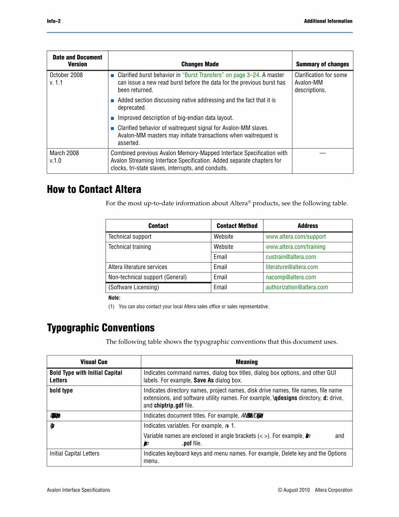
Info–2 Additional Information
How to Contact AlteraFor the most up-to-date information about Altera® products, see the following table.
Typographic ConventionsThe following table shows the typographic conventions that this document uses.
October 2008v. 1.1
■ Clarified burst behavior in “Burst Transfers” on page 3–24. A master can issue a new read burst before the data for the previous burst has been returned.
■ Added section discussing native addressing and the fact that it is deprecated.
■ Improved description of big-endian data layout.
■ Clarified behavior of waitrequest signal for Avalon-MM slaves. Avalon-MM masters may initiate transactions when waitrequest is asserted.
Clarification for some Avalon-MM descriptions.
March 2008v.1.0
Combined previous Avalon Memory-Mapped Interface Specification with Avalon Streaming Interface Specification. Added separate chapters for clocks, tri-state slaves, interrupts, and conduits.
—
Date and Document Version Changes Made Summary of changes
Contact Contact Method Address
Technical support Website www.altera.com/support
Technical training Website www.altera.com/training
Email [email protected]
Altera literature services Email [email protected]
Non-technical support (General) Email [email protected]
(Software Licensing) Email [email protected]
Note:
(1) You can also contact your local Altera sales office or sales representative.
Visual Cue Meaning
Bold Type with Initial Capital Letters
Indicates command names, dialog box titles, dialog box options, and other GUI labels. For example, Save As dialog box.
bold type Indicates directory names, project names, disk drive names, file names, file name extensions, and software utility names. For example, \qdesigns directory, d: drive, and chiptrip.gdf file.
Italic Type with Initial Capital Letters Indicates document titles. For example, AN 519: Stratix IV Design Guidelines.
Italic type Indicates variables. For example, n + 1.
Variable names are enclosed in angle brackets (< >). For example, <file name> and <project name>.pof file.
Initial Capital Letters Indicates keyboard keys and menu names. For example, Delete key and the Options menu.
Avalon Interface Specifications © August 2010 Altera Corporation

Info–3
“Subheading Title” Quotation marks indicate references to sections within a document and titles of Quartus II Help topics. For example, “Typographic Conventions.”
Courier type Indicates signal, port, register, bit, block, and primitive names. For example, data1, tdi, and input. Active-low signals are denoted by suffix n. For example, resetn.
Indicates command line commands and anything that must be typed exactly as it appears. For example, c:\qdesigns\tutorial\chiptrip.gdf.
Also indicates sections of an actual file, such as a Report File, references to parts of files (for example, the AHDL keyword SUBDESIGN), and logic function names (for example, TRI).
1., 2., 3., anda., b., c., and so on.
Numbered steps indicate a list of items when the sequence of the items is important, such as the steps listed in a procedure.
■ ■ Bullets indicate a list of items when the sequence of the items is not important.
1 The hand points to information that requires special attention.
c A caution calls attention to a condition or possible situation that can damage or destroy the product or your work.
w A warning calls attention to a condition or possible situation that can cause you injury.
r The angled arrow instructs you to press Enter.
f The feet direct you to more information about a particular topic.
Visual Cue Meaning
© August 2010 Altera Corporation Avalon Interface Specifications