automatic fuel lattice design in a boiling water reactor using a particle swarm optimization...
TRANSCRIPT
Annals of Nuclear Energy 47 (2012) 98–103
Contents lists available at SciVerse ScienceDirect
Annals of Nuclear Energy
journal homepage: www.elsevier .com/locate /anucene
Technical Note
Automatic fuel lattice design in a boiling water reactor using a particleswarm optimization algorithm and local search
Chaung Lin a,⇑, Tung-Hsien Lin b
a Department of Engineering and System Science, National Tsing Hua University, 101, Section 2 Kuang Fu Road, Hsinchu 30013, Taiwanb Institute of Nuclear Engineering and Science, National Tsing Hua University, 101, Section 2 Kuang Fu Road, Hsinchu 30013, Taiwan
a r t i c l e i n f o a b s t r a c t
Article history:Received 7 November 2011Received in revised form 31 March 2012Accepted 4 April 2012Available online 20 May 2012
Keywords:Lattice designBWRParticle swarm optimizationLocal search
0306-4549/$ - see front matter � 2012 Elsevier Ltd. Ahttp://dx.doi.org/10.1016/j.anucene.2012.04.012
⇑ Corresponding author. Fax: +886 3 5727833.E-mail address: [email protected] (C. Lin).
The axial section of fuel assembly in a boiling water reactor (BWR) consists of five or six different distri-butions; this requires a radial lattice design. In this study, an automatic procedure based on a particleswarm optimization (PSO) algorithm and local search was developed to design the radial enrichmentand gadolinia (Gd) distribution of the fuel lattice. The design goals were to achieve the minimum localpeaking factor (LPF), and to come as close as possible to the specified target average enrichment and tar-get infinite multiplication factor (k1), in which the number of fuel pins with Gd and Gd concentration arefixed. In this study, three axial sections are designed, and lattice performance is calculated using CASMO-4. Finally, the neutron cross section library of the designed lattice is established by CMSLINK; the corestatus during depletion, such as thermal limits, cold shutdown margin and cycle length, are then calcu-lated using SIMULATE-3 in order to confirm that the lattice design satisfies the design requirements.
� 2012 Elsevier Ltd. All rights reserved.
1. Introduction
The fuel assembly (FA) used in Taiwan’s BWR consists of a10 � 10 pin array, and the axial direction possesses five or six sec-tions. The top and bottom section are natural uranium only. Themiddle three or four sections adopt different enrichment and Gdconcentration fuel pins, which will determine whether or not thecore reload design fulfills the cycle energy, thermal limits andshutdown margins (SDMs). The lattice design is a part of the coremulti-cycle reload design task, in which several FAs with differentproperties are provided to meet the aforementioned requirements.In this study, in order to reduce the complexity of the problem,some factors, such as the number of Gd fuel pins, i.e., fuel pin withGd, and their concentration are specified; these are considered assearch variables in the other studies. Therefore, the search objec-tive is to place the fuel pins in proper locations such that the LPFis minimized, and the average enrichment and k1 are close tothe target values.
Several methodologies, such as Tabu search (François et al.,2003), Tabu search and fuzzy logic (Martin-del-Campo et al.,2007a), genetic algorithms and knowledge (Martin-del-Campoet al., 2007b), scatter search optimization algorithm (Françoiset al., 2007) and ant-colony-based system (Montes et al., 2011)have been applied to optimize the radial BWR fuel lattice. The objec-tive functions of the first four papers are similar; they included:
ll rights reserved.
average enrichment, deviation of k1, deviation of average Gd con-centration, and power peaking factor lower than a limit value; thedifferent method was adopted to perform minimization. As for thefifth paper, the objective function also includes these four terms,but with three different types of mathematical expression. Ortizet al. (2009) used neural networks and a fuzzy logic system to opti-mize the fuel lattice. The objective function consists of the localpower peaking factor and k1. The designed FA is verified using acore simulation code. As for the PSO applications in nuclear engi-neering, it has been applied to the nuclear engineering problem(Waintraub et al., 2009), and the core reload optimization problem(Meneses et al., 2009, 2010; Babazadeh et al., 2009; Khoshahvalet al., 2010).
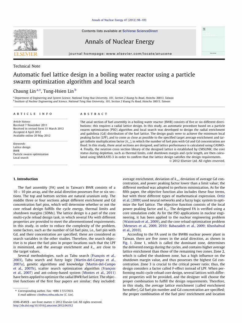
According to the FA used in the BWR6 nuclear power plant inTaiwan, there are five zones in the axial direction, as shown inFig. 1. Zone 1, which is called the dominant zone, determinesthe delivered energy during the cycles, and contains higher averagelattice enrichment than those of the remaining two zones. Zone 2,which is called the shutdown zone, has a high influence on theshutdown margin value, and thus possesses the highest Gd con-centration. Zone 3 is crucial to the critical power ratio; thus, thedesign considers a factor called F-effect instead of LPF. When per-forming multi-cycle reload core design, several lattices with differ-ent properties will be provided, and the designer will choose theproper combination to fulfill the design requirements. Therefore,in this study, the average lattice enrichment (called enrichmenthereafter), Gd fuel pin number and Gd concentration are specified;the proper combination of the fuel pins’ enrichment and location
0 15.24 243.84 320.04 350.52 379.60 (cm)
Bottom Zone1 Zone2 Zone3 Top
Fig. 1. Axial zones of the fuel assembly.
C. Lin, T.-H. Lin / Annals of Nuclear Energy 47 (2012) 98–103 99
are searched so that enrichment and k1meet the target values, andthe LPF or F-effect is minimized.
2. Particle swarm optimization (PSO)
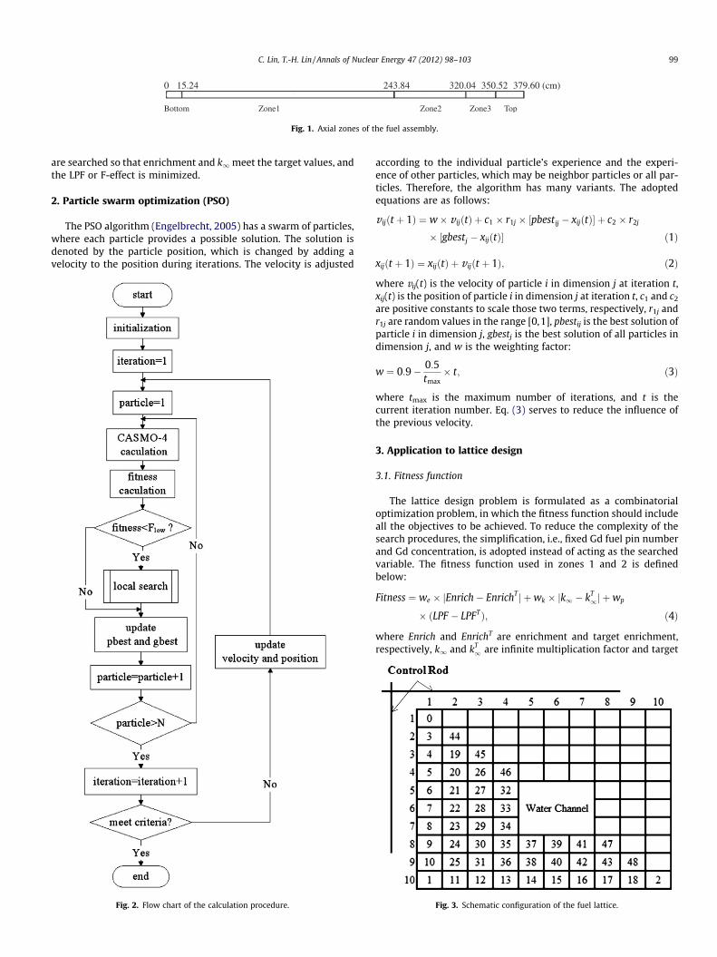
The PSO algorithm (Engelbrecht, 2005) has a swarm of particles,where each particle provides a possible solution. The solution isdenoted by the particle position, which is changed by adding avelocity to the position during iterations. The velocity is adjusted
Fig. 2. Flow chart of the calculation procedure.
according to the individual particle’s experience and the experi-ence of other particles, which may be neighbor particles or all par-ticles. Therefore, the algorithm has many variants. The adoptedequations are as follows:
v ijðt þ 1Þ ¼ w� v ijðtÞ þ c1 � r1j � ½pbestij � xijðtÞ� þ c2 � r2j
� ½gbestj � xijðtÞ� ð1Þ
xijðt þ 1Þ ¼ xijðtÞ þ v ijðt þ 1Þ; ð2Þ
where vij(t) is the velocity of particle i in dimension j at iteration t,xij(t) is the position of particle i in dimension j at iteration t, c1 and c2
are positive constants to scale those two terms, respectively, r1j andr1j are random values in the range [0,1], pbestij is the best solution ofparticle i in dimension j, gbestj is the best solution of all particles indimension j, and w is the weighting factor:
w ¼ 0:9� 0:5tmax� t; ð3Þ
where tmax is the maximum number of iterations, and t is thecurrent iteration number. Eq. (3) serves to reduce the influence ofthe previous velocity.
3. Application to lattice design
3.1. Fitness function
The lattice design problem is formulated as a combinatorialoptimization problem, in which the fitness function should includeall the objectives to be achieved. To reduce the complexity of thesearch procedures, the simplification, i.e., fixed Gd fuel pin numberand Gd concentration, is adopted instead of acting as the searchedvariable. The fitness function used in zones 1 and 2 is definedbelow:
Fitness ¼ we � jEnrich� EnrichT j þwk � jk1 � kT1j þwp
� ðLPF � LPFTÞ; ð4Þ
where Enrich and EnrichT are enrichment and target enrichment,respectively, k1 and kT
1 are infinite multiplication factor and target
Fig. 3. Schematic configuration of the fuel lattice.
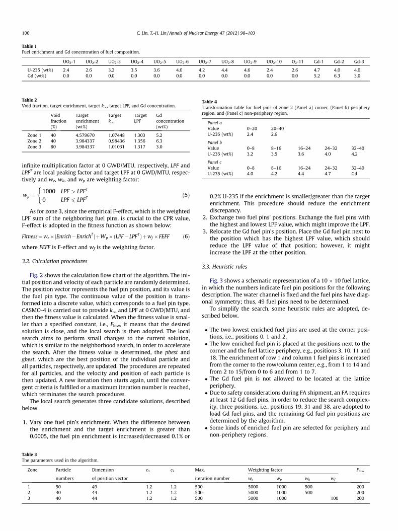
Table 1Fuel enrichment and Gd concentration of fuel composition.
UO2-1 UO2-2 UO2-3 UO2-4 UO2-5 UO2-6 UO2-7 UO2-8 UO2-9 UO2-10 O2-11 Gd-1 Gd-2 Gd-3
U-235 (wt%) 2.4 2.6 3.2 3.5 3.6 4.0 4.2 4.4 4.6 2.4 2.6 4.7 4.0 4.0Gd (wt%) 0.0 0.0 0.0 0.0 0.0 0.0 0.0 0.0 0.0 0.0 0.0 5.2 6.3 3.0
Table 2Void fraction, target enrichment, target k1, target LPF, and Gd concentration.
Void Target Target Target Gdfraction enrichment k1 LPF concentration(%) (wt%) (wt%)
Zone 1 40 4.579670 1.07448 1.303 5.2Zone 2 40 3.984337 0.98436 1.356 6.3Zone 3 80 3.984337 1.01031 1.317 3.0
Table 4Transformation table for fuel pins of zone 2 (Panel a) corner, (Panel b) peripheryregion, and (Panel c) non-periphery region.
Panel aValue 0–20 20–40U-235 (wt%) 2.4 2.6
Panel bValue 0–8 8–16 16–24 24–32 32–40U-235 (wt%) 3.2 3.5 3.6 4.0 4.2
Panel cValue 0–8 8–16 16–24 24–32 32–40U-235 (wt%) 4.0 4.2 4.4 4.7 Gd
100 C. Lin, T.-H. Lin / Annals of Nuclear Energy 47 (2012) 98–103
infinite multiplication factor at 0 GWD/MTU, respectively, LPF andLPFT are local peaking factor and target LPF at 0 GWD/MTU, respec-tively and we, wk, and wp are weighting factor:
wp ¼1000 LPF > LPFT
0 LPF 6 LPFT
(ð5Þ
As for zone 3, since the empirical F-effect, which is the weightedLPF sum of the neighboring fuel pins, is crucial to the CPR value,F-effect is adopted in the fitness function as shown below:
Fitness¼we�jEnrich�EnrichT jþWp�ðLPF�LPFTÞþwf �FEFF ð6Þ
where FEFF is F-effect and wf is the weighting factor.
3.2. Calculation procedures
Fig. 2 shows the calculation flow chart of the algorithm. The ini-tial position and velocity of each particle are randomly determined.The position vector represents the fuel pin position, and its value isthe fuel pin type. The continuous value of the position is trans-formed into a discrete value, which corresponds to a fuel pin type.CASMO-4 is carried out to provide k1 and LPF at 0 GWD/MTU, andthen the fitness value is calculated. When the fitness value is smal-ler than a specified constant, i.e., Flow, it means that the desiredsolution is close, and the local search is then adopted. The localsearch aims to perform small changes to the current solution,which is similar to the neighborhood search, in order to acceleratethe search. After the fitness value is determined, the pbest andgbest, which are the best position of the individual particle andall particles, respectively, are updated. The procedures are repeatedfor all particles, and the velocity and position of each particle isthen updated. A new iteration then starts again, until the conver-gent criteria is fulfilled or a maximum iteration number is reached,which terminates the search procedures.
The local search generates three candidate solutions, describedbelow.
1. Vary one fuel pin’s enrichment. When the difference betweenthe enrichment and the target enrichment is greater than0.0005, the fuel pin enrichment is increased/decreased 0.1% or
Table 3The parameters used in the algorithm.
Zone Particle Dimension c1 c2 Ma
numbers of position vector ite
1 50 49 1.2 1.2 5002 40 44 1.2 1.2 5003 40 44 1.2 1.2 500
0.2% U-235 if the enrichment is smaller/greater than the targetenrichment. This procedure should reduce the enrichmentdiscrepancy.
2. Exchange two fuel pins’ positions. Exchange the fuel pins withthe highest and lowest LPF value, which might improve the LPF.
3. Relocate the Gd fuel pin’s position. Place the Gd fuel pin next tothe position which has the highest LPF value, which shouldreduce the LPF value of that position; however, it mightincrease the LPF at the other position.
3.3. Heuristic rules
Fig. 3 shows a schematic representation of a 10 � 10 fuel lattice,in which the numbers indicate fuel pin positions for the followingdescription. The water channel is fixed and the fuel pins have diag-onal symmetry; thus, 49 fuel pins need to be determined.
To simplify the search, some heuristic rules are adopted, de-scribed below.
� The two lowest enriched fuel pins are used at the corner posi-tions, i.e., positions 0, 1 and 2.� The low enriched fuel pin is placed at the positions next to the
corner and the fuel lattice periphery, e.g., positions 3, 10, 11 and18. The enrichment of row 1 and column 1 fuel pins is increasedfrom the corner to the row/column center, e.g., from 1 to 14 andfrom 2 to 15/from 0 to 6 and from 1 to 7.� The Gd fuel pin is not allowed to be located at the lattice
periphery.� Due to safety considerations during FA shipment, an FA requires
at least 12 Gd fuel pins. In order to reduce the search complex-ity, three positions, i.e., positions 19, 31 and 38, are adopted toload Gd fuel pins, and the remaining Gd fuel pin positions aredetermined by the algorithm.� Some kinds of enriched fuel pin are selected for periphery and
non-periphery regions.
x. Weighting factor Flow
ration number we wp wk wf
5000 1000 500 2005000 1000 500 2005000 1000 100 200
C. Lin, T.-H. Lin / Annals of Nuclear Energy 47 (2012) 98–103 101
Since the half-length fuel pins, which are at positions 44, 21, 25,40 and 48, do not have a fuel element in zones 2 and 3, the num-bers of search variables are 49, 44 and 44 for zones 1, 2 and 3,respectively.
4. Results and discussions
The reload fuel cycle, which uses 140 designed FA, is chosen todemonstrate the capability of the developed methodology. Table 1lists the used fuel enrichment and Gd concentrations. In this study,zone 1 uses all types of enrichment, except 3.6%, and zones 2 and 3use 3.6% enrichment instead of 4.6%. Table 2 is the void fraction forcalculation, target enrichment, target k1, target LPF and Gd con-centration used in the three zones, respectively. To reduce the
Iteration
Gbe
st
Iteration
Fitn
ess
(a)
(b)
(c)
Particle Number
Pbe
st 50 15 20 25 30 35 4010
Fig. 4. Iteration results (a) the global best fitness value, (b) the best fitness value ofall particles, and (c) fitness value of all particles during iteration.
computation effort, the CASMO-4 calculation is carried out withthe selected void fraction and at 0 GWD/MTU, and the target valueis that of the reference FA. The parameters used in the algorithmare listed in Table 3.
Since the Gd fuel pin should be placed at the same radial posi-tion for the three zones, the zone 2 lattice is designed first. Table 4is the transformation table that relates the continuous particle’sposition value to the corresponding fuel type. In this study, the dif-ferent enriched fuel pins are specified based on its lattice location,e.g., the non-periphery region uses high enriched fuel pins, in orderto reduce the search complexity.
Fig. 4 shows the iteration results. Fig. 4a is the global best fit-ness value during iterations, in which the best result appears atthe 11th iteration, and the search procedure is terminated after fif-teen times, since no improvement is apparent. This criterion can berelaxed to reduce computation time. Initially, the particle’s posi-tion is randomly chosen, which had better be evenly spread inthe search space. Fig. 4b shows the best fitness value of each par-ticle at the end of an iteration, in which not all particles reach a glo-bal minimum, but all particles approach the minimum. The biggestfitness value is about 6.28; however, the deviations from the targetenrichment and target k1 are 0.001205 and 0.00051, respectively,and LPF is 1.295. The rather large fitness value is a result of thelarge value of the weighting factor. Fig. 4c shows the fitness value
Fig. 5. Designed fuel lattice of (a) zone 1, (b) zone 2, and (c) zone 3.
102 C. Lin, T.-H. Lin / Annals of Nuclear Energy 47 (2012) 98–103
of all particles during the iteration. The wide spread of the resultsindicates that the algorithm possesses exploration characteristics.
Fig. 5 shows the designed lattices of the three zones. The latticecompositions meet the heuristic rules described in Section 3.3. Thecomposition of the enriched fuel pins is different from that of the
Table 5Results of designed lattice.
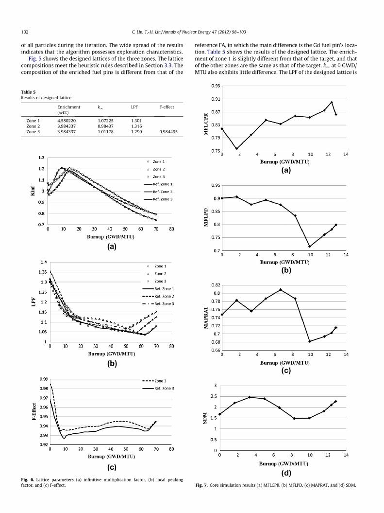
Enrichment k1 LPF F-effect(wt%)
Zone 1 4.580220 1.07225 1.301Zone 2 3.984337 0.98437 1.316Zone 3 3.984337 1.01178 1.299 0.984495
Fig. 6. Lattice parameters (a) infinitive multiplication factor, (b) local peakingfactor, and (c) F-effect.
reference FA, in which the main difference is the Gd fuel pin’s loca-tion. Table 5 shows the results of the designed lattice. The enrich-ment of zone 1 is slightly different from that of the target, and thatof the other zones are the same as that of the target. k1 at 0 GWD/MTU also exhibits little difference. The LPF of the designed lattice is
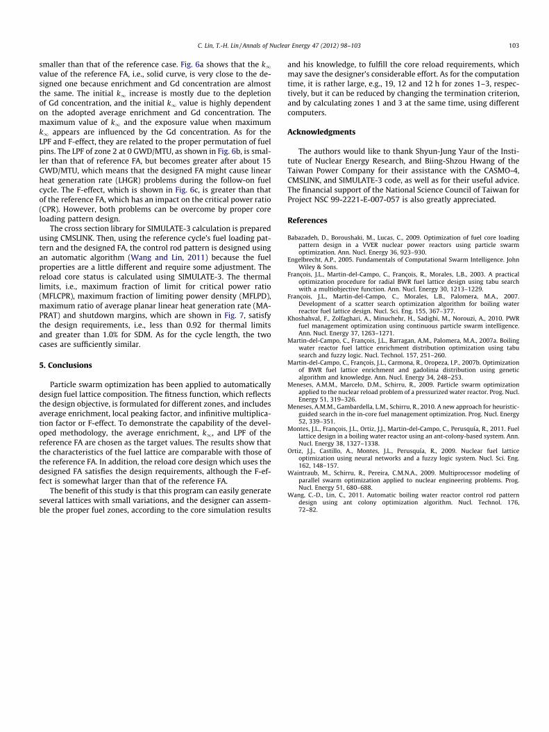
Fig. 7. Core simulation results (a) MFLCPR, (b) MFLPD, (c) MAPRAT, and (d) SDM.
C. Lin, T.-H. Lin / Annals of Nuclear Energy 47 (2012) 98–103 103
smaller than that of the reference case. Fig. 6a shows that the k1value of the reference FA, i.e., solid curve, is very close to the de-signed one because enrichment and Gd concentration are almostthe same. The initial k1 increase is mostly due to the depletionof Gd concentration, and the initial k1 value is highly dependenton the adopted average enrichment and Gd concentration. Themaximum value of k1 and the exposure value when maximumk1 appears are influenced by the Gd concentration. As for theLPF and F-effect, they are related to the proper permutation of fuelpins. The LPF of zone 2 at 0 GWD/MTU, as shown in Fig. 6b, is smal-ler than that of reference FA, but becomes greater after about 15GWD/MTU, which means that the designed FA might cause linearheat generation rate (LHGR) problems during the follow-on fuelcycle. The F-effect, which is shown in Fig. 6c, is greater than thatof the reference FA, which has an impact on the critical power ratio(CPR). However, both problems can be overcome by proper coreloading pattern design.
The cross section library for SIMULATE-3 calculation is preparedusing CMSLINK. Then, using the reference cycle’s fuel loading pat-tern and the designed FA, the control rod pattern is designed usingan automatic algorithm (Wang and Lin, 2011) because the fuelproperties are a little different and require some adjustment. Thereload core status is calculated using SIMULATE-3. The thermallimits, i.e., maximum fraction of limit for critical power ratio(MFLCPR), maximum fraction of limiting power density (MFLPD),maximum ratio of average planar linear heat generation rate (MA-PRAT) and shutdown margins, which are shown in Fig. 7, satisfythe design requirements, i.e., less than 0.92 for thermal limitsand greater than 1.0% for SDM. As for the cycle length, the twocases are sufficiently similar.
5. Conclusions
Particle swarm optimization has been applied to automaticallydesign fuel lattice composition. The fitness function, which reflectsthe design objective, is formulated for different zones, and includesaverage enrichment, local peaking factor, and infinitive multiplica-tion factor or F-effect. To demonstrate the capability of the devel-oped methodology, the average enrichment, k1, and LPF of thereference FA are chosen as the target values. The results show thatthe characteristics of the fuel lattice are comparable with those ofthe reference FA. In addition, the reload core design which uses thedesigned FA satisfies the design requirements, although the F-ef-fect is somewhat larger than that of the reference FA.
The benefit of this study is that this program can easily generateseveral lattices with small variations, and the designer can assem-ble the proper fuel zones, according to the core simulation results
and his knowledge, to fulfill the core reload requirements, whichmay save the designer’s considerable effort. As for the computationtime, it is rather large, e.g., 19, 12 and 12 h for zones 1–3, respec-tively, but it can be reduced by changing the termination criterion,and by calculating zones 1 and 3 at the same time, using differentcomputers.
Acknowledgments
The authors would like to thank Shyun-Jung Yaur of the Insti-tute of Nuclear Energy Research, and Biing-Shzou Hwang of theTaiwan Power Company for their assistance with the CASMO-4,CMSLINK, and SIMULATE-3 code, as well as for their useful advice.The financial support of the National Science Council of Taiwan forProject NSC 99-2221-E-007-057 is also greatly appreciated.
References
Babazadeh, D., Boroushaki, M., Lucas, C., 2009. Optimization of fuel core loadingpattern design in a VVER nuclear power reactors using particle swarmoptimization. Ann. Nucl. Energy 36, 923–930.
Engelbrecht, A.P., 2005. Fundamentals of Computational Swarm Intelligence. JohnWiley & Sons.
François, J.L., Martin-del-Campo, C., François, R., Morales, L.B., 2003. A practicaloptimization procedure for radial BWR fuel lattice design using tabu searchwith a multiobjective function. Ann. Nucl. Energy 30, 1213–1229.
François, J.L., Martin-del-Campo, C., Morales, L.B., Palomera, M.A., 2007.Development of a scatter search optimization algorithm for boiling waterreactor fuel lattice design. Nucl. Sci. Eng. 155, 367–377.
Khoshahval, F., Zolfaghari, A., Minuchehr, H., Sadighi, M., Norouzi, A., 2010. PWRfuel management optimization using continuous particle swarm intelligence.Ann. Nucl. Energy 37, 1263–1271.
Martin-del-Campo, C., François, J.L., Barragan, A.M., Palomera, M.A., 2007a. Boilingwater reactor fuel lattice enrichment distribution optimization using tabusearch and fuzzy logic. Nucl. Technol. 157, 251–260.
Martin-del-Campo, C., François, J.L., Carmona, R., Oropeza, I.P., 2007b. Optimizationof BWR fuel lattice enrichment and gadolinia distribution using geneticalgorithm and knowledge. Ann. Nucl. Energy 34, 248–253.
Meneses, A.M.M., Marcelo, D.M., Schirru, R., 2009. Particle swarm optimizationapplied to the nuclear reload problem of a pressurized water reactor. Prog. Nucl.Energy 51, 319–326.
Meneses, A.M.M., Gambardella, L.M., Schirru, R., 2010. A new approach for heuristic-guided search in the in-core fuel management optimization. Prog. Nucl. Energy52, 339–351.
Montes, J.L., François, J.L., Ortiz, J.J., Martin-del-Campo, C., Perusquía, R., 2011. Fuellattice design in a boiling water reactor using an ant-colony-based system. Ann.Nucl. Energy 38, 1327–1338.
Ortiz, J.J., Castillo, A., Montes, J.L., Perusquía, R., 2009. Nuclear fuel latticeoptimization using neural networks and a fuzzy logic system. Nucl. Sci. Eng.162, 148–157.
Waintraub, M., Schirru, R., Pereira, C.M.N.A., 2009. Multiprocessor modeling ofparallel swarm optimization applied to nuclear engineering problems. Prog.Nucl. Energy 51, 680–688.
Wang, C.-D., Lin, C., 2011. Automatic boiling water reactor control rod patterndesign using ant colony optimization algorithm. Nucl. Technol. 176,72–82.