automatic capacitor banks · 440 kvar capacitor bank composition: (40 + 5x80) this capaci-tor bank...
TRANSCRIPT
Automatic capacitor banks
Unit 6/22 Moselle Ave, Henderson, Auckland, New Zealand PO Box 21-872, Henderson, Auckland, New Zealand
Phone:+64 9 833 5749Email:[email protected]
Web: www.LPINZ.co.nzNEW ZEALANDWWW.LPINZ.CO.NZ

R3-2
Automatic capacitors banksACFCS Capacitor with contactor and fuses · · · · · · · · · · · · · · · · · · · · · · · · · · · · · · · · · · · · · · · · · · · · · · · · · · · · · · · · · · · · · · · · · · · · · · · · · · R3-4
OPTIM 1Regulated capacitors · · · · · · · · · · · · · · · · · · · · · · · · · · · · · · · · · · · · · · · · · · · · · · · · · · · · · · · · · · · · · · · · · · · · · · · · · · · · · · · · · · · · · · · · R3-6
OPTIMAutomatic capacitor banks · · · · · · · · · · · · · · · · · · · · · · · · · · · · · · · · · · · · · · · · · · · · · · · · · · · · · · · · · · · · · · · · · · · · · · · · · · · · · · · · · · · R3-8
Automatic capacitor banks
R3-3
Automatic capacitor banks
R.3CIRCUTOR's range of capacitor banks for contactor switching operations cover power levels 7.5 kvar to 1120 kvar (in the case of greater power levels, please ask).
Initial data:
Data that must be taken into account when selecting a capacitor bank:
}} Total power factor consumption of the installation and cos φ objective.}} Voltage: the voltage of the unit must
always be equal to or higher than the network voltage.}} Harmonic distortion levels}} Simultaneity of loads.}} Regulation of the capacitor bank: we
recommend an approximate power of 10% of the total power of the unit in the first step.
Technical instruction ITC-BT-43 of the REBT, section 2.7 (Power factor correc-tion) must be taken into account when selecting a capacitor bank:
The installations that supply energy to receivers with a power factor under 1 can be compensated. However, the en-ergy absorbed by the network can not be capacitive.
combinations of the unit. The number of electrical steps is the result of dividing the total power of the unit by the power of the lowest step. Here is an example.
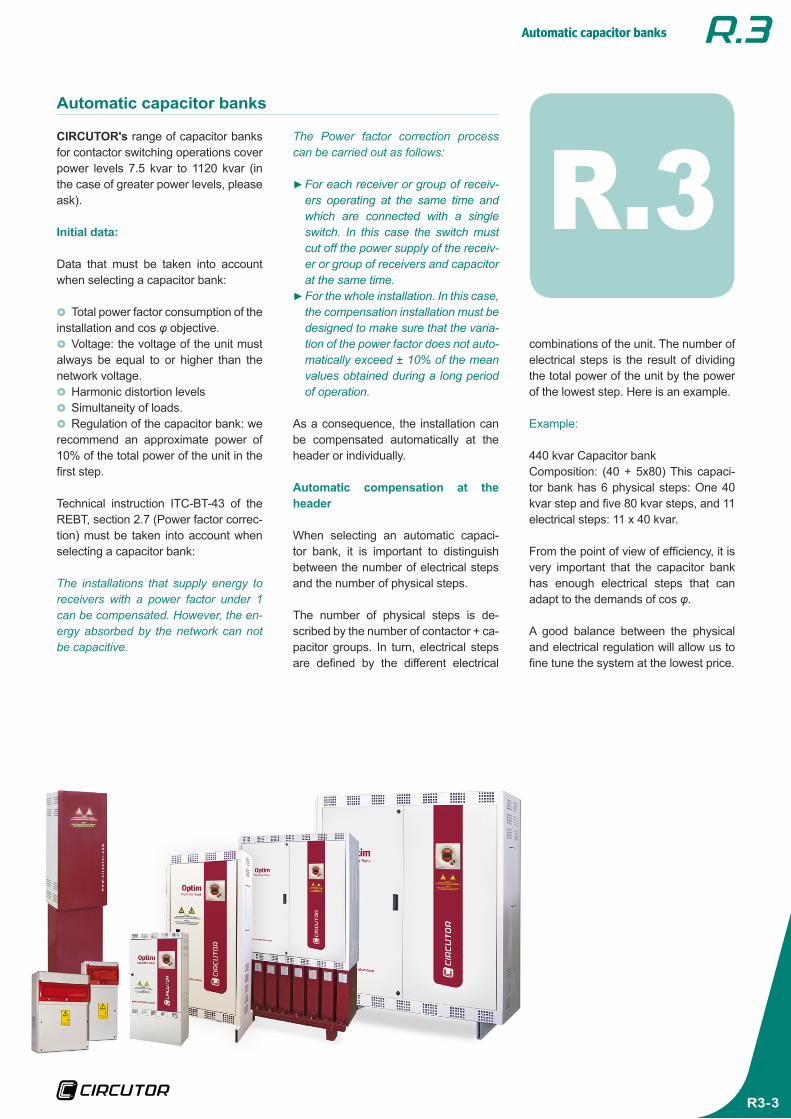
Example:
440 kvar Capacitor bank Composition: (40 + 5x80) This capaci-tor bank has 6 physical steps: One 40 kvar step and five 80 kvar steps, and 11 electrical steps: 11 x 40 kvar.
From the point of view of efficiency, it is very important that the capacitor bank has enough electrical steps that can adapt to the demands of cos φ.
A good balance between the physical and electrical regulation will allow us to fine tune the system at the lowest price.
The Power factor correction process can be carried out as follows:
}►For each receiver or group of receiv-ers operating at the same time and which are connected with a single switch. In this case the switch must cut off the power supply of the receiv-er or group of receivers and capacitor at the same time.}►For the whole installation. In this case, the compensation installation must be designed to make sure that the varia-tion of the power factor does not auto-matically exceed ± 10% of the mean values obtained during a long period of operation.
As a consequence, the installation can be compensated automatically at the header or individually.
Automatic compensation at the header
When selecting an automatic capaci-tor bank, it is important to distinguish between the number of electrical steps and the number of physical steps.
The number of physical steps is de-scribed by the number of contactor + ca-pacitor groups. In turn, electrical steps are defined by the different electrical
Automatic capacitor banks
R3-4
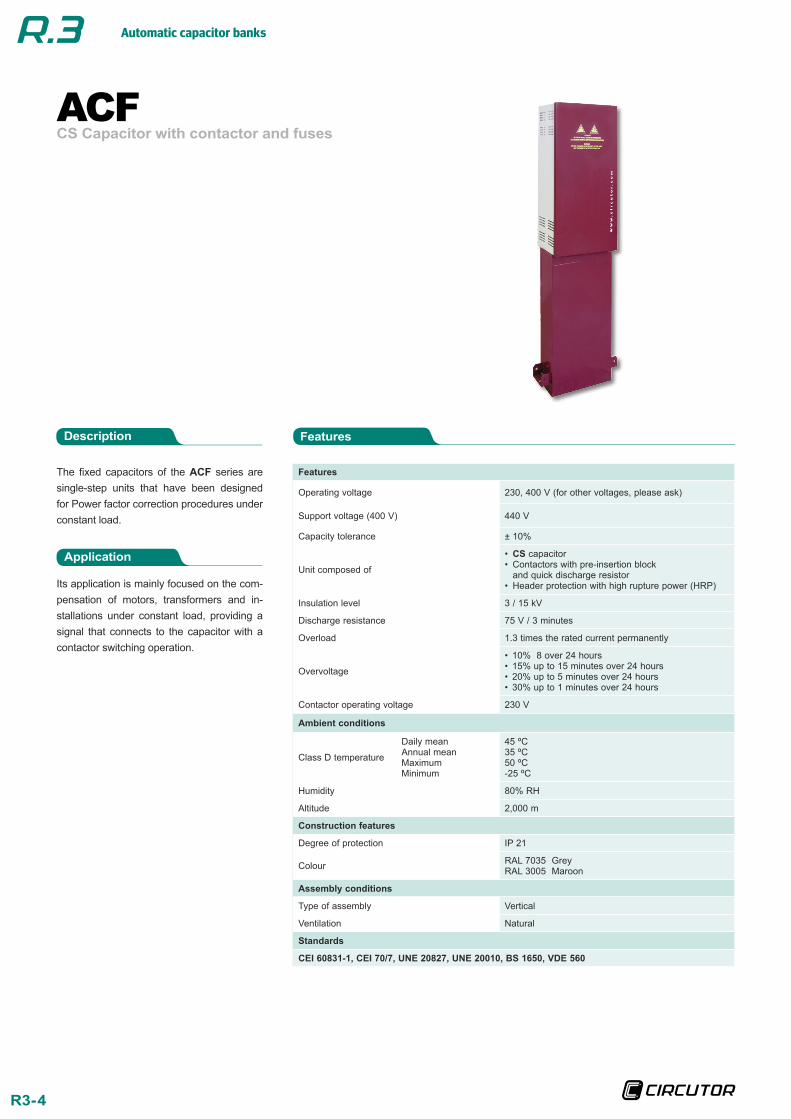
ACFCS Capacitor with contactor and fuses
The fixed capacitors of the ACF series are single-step units that have been designed for Power factor correction procedures under constant load.
Application
Its application is mainly focused on the com-pensation of motors, transformers and in-stallations under constant load, providing a signal that connects to the capacitor with a contactor switching operation.
FeaturesDescription
Features
Operating voltage 230, 400 V (for other voltages, please ask)
Support voltage (400 V) 440 V
Capacity tolerance ± 10%
Unit composed of
• CS capacitor • Contactors with pre-insertion block and quick discharge resistor
• Header protection with high rupture power (HRP)
Insulation level 3 / 15 kV
Discharge resistance 75 V / 3 minutes
Overload 1.3 times the rated current permanently
Overvoltage
• 10% 8 over 24 hours • 15% up to 15 minutes over 24 hours • 20% up to 5 minutes over 24 hours • 30% up to 1 minutes over 24 hours
Contactor operating voltage 230 V
Ambient conditions
Class D temperature
Daily meanAnnual meanMaximumMinimum
45 ºC35 ºC50 ºC-25 ºC
Humidity 80% RH
Altitude 2,000 m
Construction features
Degree of protection IP 21
Colour RAL 7035 GreyRAL 3005 Maroon
Assembly conditions
Type of assembly Vertical
Ventilation Natural
Standards
CEI 60831-1, CEI 70/7, UNE 20827, UNE 20010, BS 1650, VDE 560

Automatic capacitor banks
R3-5
230 V
kvar Cut off power (A) Fuses Cable section
(mm2) Weight (kg) Dimensions (mm) width x height x depth Type Code
20 120 kA 50 125 25 17 360 x 868 x 140 ACF-20-230 R3S141
25 120 kA 63 125 35 21 360 x 1093 x 140 ACF-25-230 R3S151
30 120 kA 75 160 50 22 360 x 1093 x 140 ACF-30-230 R3S161
40 120 kA 100 160 70 27 360 x 1093 x 140 ACF-40-230 R3S181
440 V
kvar Cut off power (A) Fuses Cable section
(mm2) Weight (kg) Dimensions (mm) width x height x depth Type Code
440 400
12,5 10 120 kA 16 35 6 12 360 x 868 x 140 ACF-12.5-440 R3S421
15 12,5 120 kA 20 35 10 13 360 x 868 x 140 ACF-15-440 R3S431
20 17 120 kA 26 50 10 14 360 x 868 x 140 ACF-20-440 R3S441
25 21 120 kA 33 63 10 15 360 x 868 x 140 ACF-25-440 R3S451
30 25 120 kA 39 80 16 16 360 x 868 x 140 ACF-30-440 R3S461
37,5 31 120 kA 49 80 25 17 360 x 868 x 140 ACF-37.5-440 R3S481
50 42 120 kA 66 125 35 21 360 x 868 x 140 ACF-50-440 R3S491
60 50 120 kA 79 160 50 22 360 x 1093 x 140 ACF-60-440 R3S4A1
75 63 120 kA 99 160 70 24 360 x 1093 x 140 ACF-75-440 R3S4B1
100 80 120 kA 131 160 70 29 360 x 1093 x 140 ACF-100-440 R3S4D1
ACFCS Capacitor with contactor and fuses
Dimensions
References
A (mm)
ACF-50 324
ACF-100 549
Automatic capacitor banks
R3-6
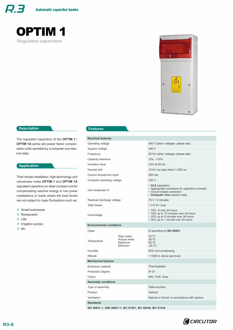
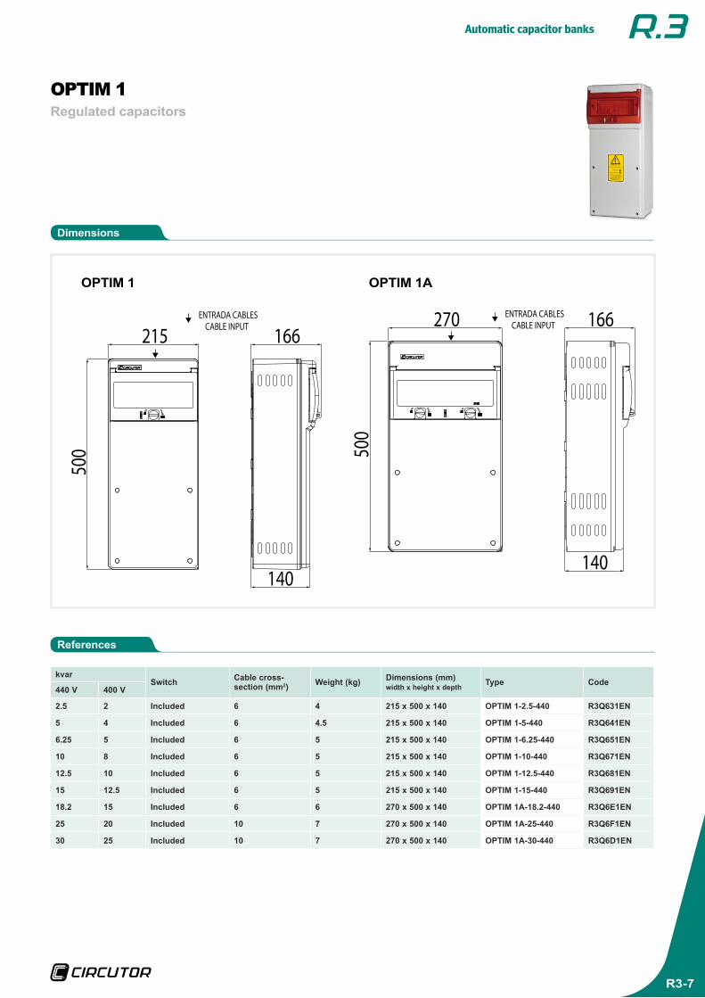
OPTIM 1Regulated capacitors
The regulated capacitors of the OPTIM 1 / OPTIM 1A series are power factor compen-sation units operated by a computer one reac-tive relay.
Application
Their simple installation, high-technology and robustness make OPTIM 1 and OPTIM 1A regulated capacitors an ideal compact unit for compensating reactive energy in low power installations or loads where the load levels are not subject to major fluctuations such as:
}} Small businesses}} Restaurants}} Lifts}} Irrigation pumps}} etc.
FeaturesDescription
Electrical features
Operating voltage 400 V (other voltages: please ask)
Support voltage 440 V
Frequency 50 Hz (other voltages: please ask)
Capacity tolerance -5%...+10%
Insulation level 3 kV at 50 Hz
Impulse test 15 kV, ray type wave 1.2/50 µs
Current transformer input 250 mA
Contactor operating voltage 230 V
Unit composed of
• CLZ capacitors • Appropriate contactors for capacitive currents • Circuit breaker protection • Computer One reactive relay
Residual discharge voltage 75 V / 3 minutes
Total losses < 0.5 W / kvar
Overvoltage
• 10% 8 over 24 hours • 15% up to 15 minutes over 24 hours • 20% up to 5 minutes over 24 hours • 30% up to 1 minute over 24 hours
Environmental conditions
Class D according to IEC-60831
Temperature
Daily meanAnnual meanMaximumMinimum
45 ºC35 ºC55 ºC-25 ºC
Humidity 80% non-condensing
Altitude < 1000 m above sea level.
Mechanical features
Enclosure material Thermoplastic
Protection Degree IP 21
Colour RAL 7035 Grey
Assembly conditions
Type of assembly Wall-mounted
Position Vertical
Ventilation Natural or forced, in accordance with options
Standards
IEC 60831-1, UNE 60831-1, IEC 61921, IEC 60439, IEC 61439
Automatic capacitor banks
R3-7
kvarSwitch Cable cross-
section (mm2) Weight (kg) Dimensions (mm) width x height x depth Type Code
440 V 400 V
2.5 2 Included 6 4 215 x 500 x 140 OPTIM 1-2.5-440 R3Q631EN
5 4 Included 6 4.5 215 x 500 x 140 OPTIM 1-5-440 R3Q641EN
6.25 5 Included 6 5 215 x 500 x 140 OPTIM 1-6.25-440 R3Q651EN
10 8 Included 6 5 215 x 500 x 140 OPTIM 1-10-440 R3Q671EN
12.5 10 Included 6 5 215 x 500 x 140 OPTIM 1-12.5-440 R3Q681EN
15 12.5 Included 6 5 215 x 500 x 140 OPTIM 1-15-440 R3Q691EN
18.2 15 Included 6 6 270 x 500 x 140 OPTIM 1A-18.2-440 R3Q6E1EN
25 20 Included 10 7 270 x 500 x 140 OPTIM 1A-25-440 R3Q6F1EN
30 25 Included 10 7 270 x 500 x 140 OPTIM 1A-30-440 R3Q6D1EN
OPTIM 1Regulated capacitors
Dimensions
References
500
215 166
140
ENTRADA CABLESCABLE INPUT 270
500
166
140
ENTRADA CABLESCABLE INPUT
OPTIM 1 OPTIM 1A
Automatic capacitor banks
R3-8
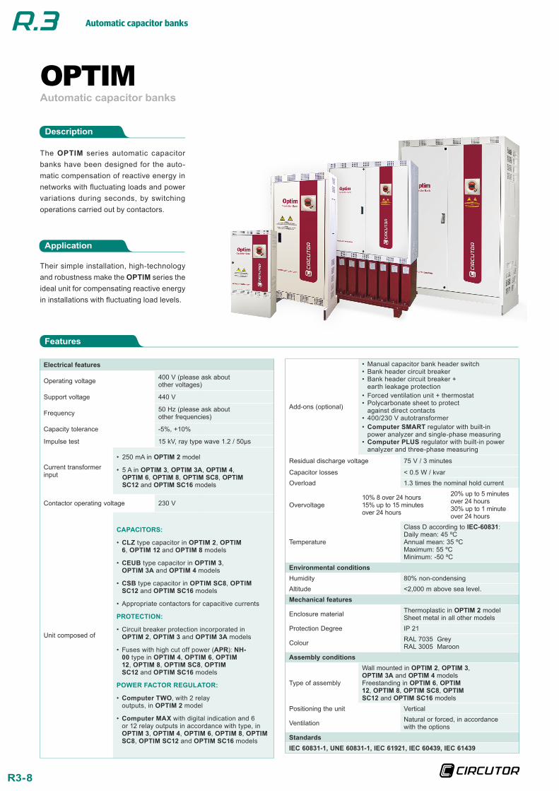
Automatic capacitor banksOPTIM
The OPTIM series automatic capacitor banks have been designed for the auto-matic compensation of reactive energy in networks with fluctuating loads and power variations during seconds, by switching operations carried out by contactors.
Application
Their simple installation, high-technology and robustness make the OPTIM series the ideal unit for compensating reactive energy in installations with fluctuating load levels.
Features
Description
Electrical features
Operating voltage 400 V (please ask about other voltages)
Support voltage 440 V
Frequency 50 Hz (please ask about other frequencies)
Capacity tolerance -5%, +10%
Impulse test 15 kV, ray type wave 1.2 / 50µs
Current transformer input
• 250 mA in OPTIM 2 model
• 5 A in OPTIM 3, OPTIM 3A, OPTIM 4, OPTIM 6, OPTIM 8, OPTIM SC8, OPTIM SC12 and OPTIM SC16 models
Contactor operating voltage 230 V
Unit composed of
CAPACITORS:
• CLZ type capacitor in OPTIM 2, OPTIM 6, OPTIM 12 and OPTIM 8 models
• CEUB type capacitor in OPTIM 3, OPTIM 3A and OPTIM 4 models
• CSB type capacitor in OPTIM SC8, OPTIM SC12 and OPTIM SC16 models
• Appropriate contactors for capacitive currents
PROTECTION:
• Circuit breaker protection incorporated in OPTIM 2, OPTIM 3 and OPTIM 3A models
• Fuses with high cut off power (APR): NH-00 type in OPTIM 4, OPTIM 6, OPTIM 12, OPTIM 8, OPTIM SC8, OPTIM SC12 and OPTIM SC16 models
POWER FACTOR REgULATOR:
• Computer TWO, with 2 relay outputs, in OPTIM 2 model
• Computer MAX with digital indication and 6 or 12 relay outputs in accordance with type, in OPTIM 3, OPTIM 4, OPTIM 6, OPTIM 8, OPTIM SC8, OPTIM SC12 and OPTIM SC16 models
Add-ons (optional)
• Manual capacitor bank header switch • Bank header circuit breaker • Bank header circuit breaker + earth leakage protection
• Forced ventilation unit + thermostat • Polycarbonate sheet to protect against direct contacts
• 400/230 V autotransformer • Computer SMART regulator with built-in power analyzer and single-phase measuring
• Computer PLUS regulator with built-in power analyzer and three-phase measuring
Residual discharge voltage 75 V / 3 minutes
Capacitor losses < 0.5 W / kvarOverload 1.3 times the nominal hold current
Overvoltage10% 8 over 24 hours15% up to 15 minutes over 24 hours
20% up to 5 minutes over 24 hours30% up to 1 minute over 24 hours
Temperature
Class D according to IEC-60831:Daily mean: 45 ºCAnnual mean: 35 ºCMaximum: 55 ºCMinimum: -50 ºC
Environmental conditionsHumidity 80% non-condensingAltitude <2,000 m above sea level.Mechanical features
Enclosure material Thermoplastic in OPTIM 2 modelSheet metal in all other models
Protection Degree IP 21
Colour RAL 7035 GreyRAL 3005 Maroon
Assembly conditions
Type of assembly
Wall mounted in OPTIM 2, OPTIM 3, OPTIM 3A and OPTIM 4 modelsFreestanding in OPTIM 6, OPTIM 12, OPTIM 8, OPTIM SC8, OPTIM SC12 and OPTIM SC16 models
Positioning the unit Vertical
Ventilation Natural or forced, in accordance with the options
StandardsIEC 60831-1, UNE 60831-1, IEC 61921, IEC 60439, IEC 61439
Automatic capacitor banks
R3-9
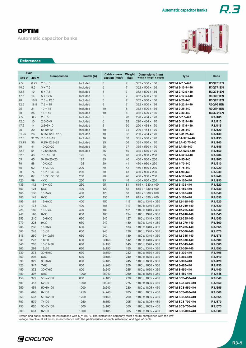
References
Automatic capacitor banksOPTIM
kvarComposition Switch (A) Cable cross-
section (mm2)Weight
(kg)Dimensions (mm)
width x height x depth Type Code440 V 400 V
7.5 6.25 2.5 + 5 Included 6 7 362 x 500 x 166 OPTIM 2-7.5-440 R3Q761EN10.5 8.5 3 + 7.5 Included 6 7 362 x 500 x 166 OPTIM 2-10.5-440 R3Q771EN12.5 10 5 + 7.5 Included 6 7 362 x 500 x 166 OPTIM 2-12.5-440 R3Q781EN17.5 14 5 + 12.5 Included 6 7 362 x 500 x 166 OPTIM 2-17.5-440 R3Q7E1EN20 16.5 7.5 + 12.5 Included 6 7 362 x 500 x 166 OPTIM 2-20-440 R3Q7F1EN22.5 18.5 7.5 + 15 Included 6 7 362 x 500 x 166 OPTIM 2-22.5-440 R3Q7g1EN25 21 10 + 15 Included 10 8 362 x 500 x 166 OPTIM 2-25-440 R3Q7H1EN30 25 15 + 15 Included 10 8 362 x 500 x 166 OPTIM 2-30-440 R3Q7J1EN7.5 6.2 2.5+5 Included 6 28 290 x 464 x 170 OPTIM 3-7.5-440 R3J10512.5 10 2.5+5+5 Included 6 28 290 x 464 x 170 OPTIM 3-12.5-440 R3J11017.5 14 2.5+5+10 Included 6 30 290 x 464 x 170 OPTIM 3-17.5-440 R3J11525 20 5+10+10 Included 10 31 290 x 464 x 170 OPTIM 3-25-440 R3J12031.25 26 6.25+12.5+12.5 Included 10 32 290 x 464 x 170 OPTIM 3-31.25-440 R3J13037.5 31.25 7.5+15+15 Included 16 33 335 x 560 x 170 OPTIM 3A-37.5-440 R3J13543.75 36 6.25+12.5+25 Included 25 36 335 x 560 x 170 OPTIM 3A-43.75-440 R3J14050 41 10+20+20 Included 25 37 335 x 560 x 170 OPTIM 3A-50-440 R3J14562.5 51 12.5+25+25 Included 35 40 335 x 560 x 170 OPTIM 3A-62.5-440 R3J15052.5 43 7.5+15+30 125 35 40 460 x 930 x 230 OPTIM 4-52.5-440 R3J20455 45 5+10+20+20 125 35 40 460 x 930 x 230 OPTIM 4-55-440 R3J20570 58 10+3x20 125 50 41 460 x 930 x 230 OPTIM 4-70-440 R3J21075 62 15+30+30 200 70 42 460 x 930 x 230 OPTIM 4-75-440 R3J22090 74 15+15+30+30 200 70 43 460 x 930 x 230 OPTIM 4-90-440 R3J230105 87 15+30+30+30 200 70 46 460 x 930 x 230 OPTIM 4-105-440 R3J240120 99 4x30 250 95 48 460 x 930 x 230 OPTIM 4-120-440 R3J250135 112 15+4x30 250 95 81 615 x 1330 x 400 OPTIM 6-135-440 R3J320150 124 5x30 400 120 82 615 x 1330 x 400 OPTIM 6-150-440 R3J330165 136 15+5x30 400 120 83 615 x 1330 x 400 OPTIM 6-165-440 R3J340180 149 6x30 400 150 87 615 x 1330 x 400 OPTIM 6-180-440 R3J350195 161 15+6x30 400 150 117 1180 x 1340 x 360 OPTIM 12-195-440 R3J520210 173 7x30 400 185 119 1180 x 1340 x 360 OPTIM 12-210-440 R3J530225 186 15+7x30 400 185 121 1180 x 1340 x 360 OPTIM 12-225-440 R3J540240 198 8x30 630 185 124 1180 x 1340 x 360 OPTIM 12-240-440 R3J545255 210 15+8x30 630 240 127 1180 x 1340 x 360 OPTIM 12-255-440 R3J550270 223 9x30 630 240 130 1180 x 1340 x 360 OPTIM 12-270-440 R3J560285 235 15+9x30 630 240 133 1180 x 1340 x 360 OPTIM 12-285-440 R3J565300 248 10x30 630 240 136 1180 x 1340 x 360 OPTIM 12-300-440 R3J570315 260 15+10x30 630 240 139 1180 x 1340 x 360 OPTIM 12-315-440 R3J575330 273 11x30 630 2x150 142 1180 x 1340 x 360 OPTIM 12-330-440 R3J580345 285 15+11x30 630 2x150 145 1180 x 1340 x 360 OPTIM 12-345-440 R3J585360 298 12x30 630 2x150 155 1180 x 1340 x 360 OPTIM 12-360-440 R3J590330 273 30+5x60 630 2x150 232 1180 x 1650 x 360 OPTIM 8-330-440 R3J405360 298 6x60 630 2x185 240 1180 x 1650 x 360 OPTIM 8-360-440 R3J410390 322 30+6x60 800 2x185 245 1180 x 1650 x 360 OPTIM 8-390-440 R3J420420 347 7x60 800 2x240 250 1180 x 1650 x 360 OPTIM 8-420-440 R3J430450 372 30+7x60 800 2x240 255 1180 x 1650 x 360 OPTIM 8-450-440 R3J440480 397 8x60 1000 2x240 260 1180 x 1650 x 360 OPTIM 8-480-440 R3J445450 372 50+4x100 800 2x185 270 1180 x 1805 x 460 OPTIM SC8-450-440 R3J640500 413 5x100 1000 2x240 275 1180 x 1805 x 460 OPTIM SC8-500-440 R3J650550 454 50+5x100 1000 2x240 280 1180 x 1805 x 460 OPTIM SC8-550-440 R3J655600 496 6x100 1250 2x240 285 1180 x 1805 x 460 OPTIM SC8-600-440 R3J660650 537 50+6x100 1250 3x150 290 1180 x 1805 x 460 OPTIM SC8-650-440 R3J665700 579 7x100 1250 3x150 295 1180 x 1805 x 460 OPTIM SC8-700-440 R3J670750 620 50+7x100 1600 3x185 300 1180 x 1805 x 460 OPTIM SC8-750-440 R3J675800 661 8x100 1600 3x185 305 1180 x 1805 x 460 OPTIM SC8-800-440 R3J680Switch and cable section for installations with Un= 400 V. The installation company must ensure compliance with the low voltage directive at all times, in accordance with the particularities of each installation and type of cable.
Automatic capacitor banks
R3-10
kvarComposition Switch (A) Cable cross-
section (mm2)Weight
(kg)Dimensions (mm)
width x height x depth Type Code440 V 400 V
900 744 9x100 1250 / 400 3x150 / 185 525 1930 x 1805 x 460 OPTIM SC12-900-440 R3J765950 785 50+9x100 1600 / 400 3x185 / 185 535 1930 x 1805 x 460 OPTIM SC12-950-440 R3J7701000 826 10x100 1600 / 400 3x185 / 185 545 1930 x 1805 x 460 OPTIM SC12-1000-440 R3J7751050 868 50+10x100 1600 / 630 3x185 / 240 555 1930 x 1805 x 460 OPTIM SC12-1050-440 R3J7801100 909 11x100 1600 / 630 3x185 / 2x120 565 1930 x 1805 x 460 OPTIM SC12-1100-440 R3J7851150 950 50+11x100 1600 / 800 3x185 / 2x150 575 1930 x 1805 x 460 OPTIM SC12-1150-440 R3J7901200 992 12x100 1600 / 800 3x185 / 2x185 585 1930 x 1805 x 460 OPTIM SC12-1200-440 R3J7951300 1074 100+6x200 1250 / 1250 3x185 / 2x240 590 2460 x 1805 x 460 OPTIM SC16-1300-440 R3J8801400 1157 100+100+6x200 1600 / 1250 3x185 / 3x120 595 2460 x 1805 x 460 OPTIM SC16-1400-440 R3J8851500 1240 100+7x200 1600 / 1600 3x185 / 3x150 600 2460 x 1805 x 460 OPTIM SC16-1500-440 R3J8901600 1322 100+100+7x200 1600 / 1600 3x185 / 3x185 605 2460 x 1805 x 460 OPTIM SC16-1600-440 R3J895
Switch and cable section for installations with Un= 400 V. The installation company must ensure compliance with the low voltage directive at all times, in accordance with the particularities of each installation and type of cable.
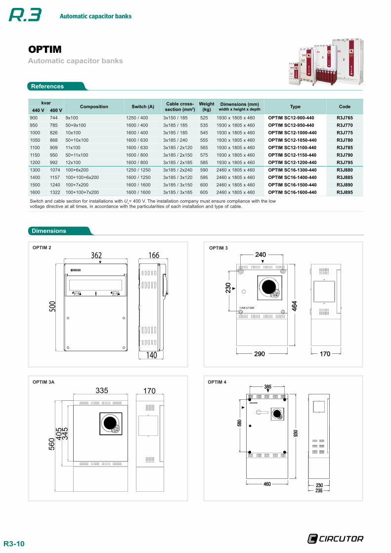
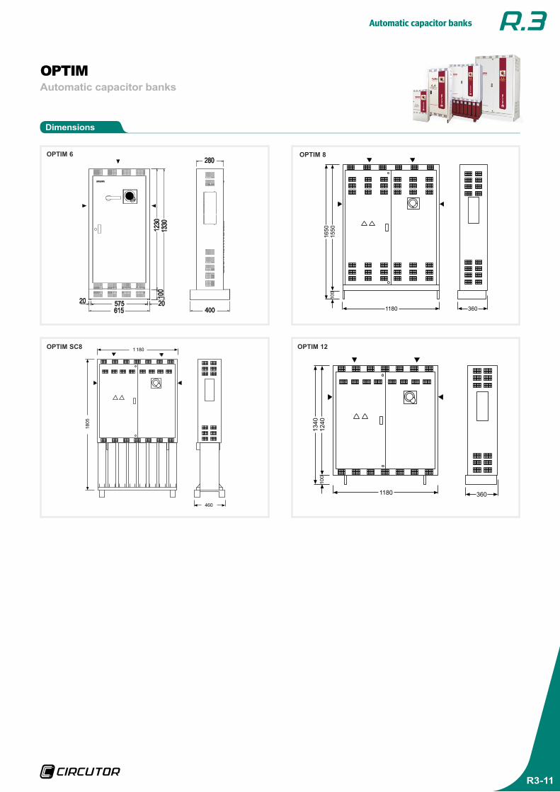
Dimensions
Automatic capacitor banksOPTIM
OPTIM 2
OPTIM 3A
OPTIM 3
OPTIM 4
References
500
166
140
362
335 170
560 40
534
5
Automatic capacitor banks
R3-11
Automatic capacitor banksOPTIM
Dimensions
OPTIM 6
OPTIM SC8
OPTIM 8
OPTIM 12
13
40
12
40
10
0
1180 360
1650
1550
100
1180 360
18
05
1 180
460
Automatic capacitor banks, LV
CIRCUTOR, SA reserves the right to change any of the information contained in this catalogue.
CIRCUTOR, SA - Vial Sant Jordi, s/n 08232 Viladecavalls (Barcelona) España Tel. (+34) 93 745 29 00 - Fax: (+34) 93 745 29 14 [email protected]
www.circutor.com
Des
ign
ed b
y: C
om
un
icat
ion
& im
age
dp
t o
f C
IRC
UT
OR
, SA
+ information: [email protected]