autodesk revit 2018 architectural command reference · constrain the placement of beams. structural...
TRANSCRIPT

ACCESS CODEUNIQUE CODE INSIDE
Revit 2018 Architectural Command Reference
Autodesk
Daniel John Stine CSI, CDT Jeff Hanson
®
®
SDCP U B L I C AT I O N S www.SDCpublications.com
Better Textbooks. Lower Prices.

Visit the following websites to learn more about this book:
Powered by TCPDF (www.tcpdf.org)

Chapter 4
Structure Tab The Structure tab contains tools to model or document the structural elements of a building, such as columns, beams, footings, etc. Some of the tools on this tab have already been covered in the previous chapter and will not be repeated; a note is added to refer to the previous chapter in each case. Additionally, given the platform/architectural focus of this book, the reinforcement tools will not be covered.

4-2 Chapter 4 – Structure Tab
4.1 Structure tab: Structure panel The Structural panel contains the fundamental structural element commands. These tools are used by architects and structural engineers to model existing conditions and new construction. The icon in the lower right opens the Structural Settings dialog, which is covered in the Manage tab chapter.
It is often helpful to model structural elements in the order they are actually built, which directly corresponds to how things are supported… for example, a beam is supported by a column or structural wall. However, footings and foundations are often modeled last, unless modeling existing conditions.
It is often best to add Grids first and then Columns and/or Structural Walls. Once the columns/walls are in place, Beams will automatically connect and clean up with them.
One more thing to point out: architectural plans are a view of the model from the floor up. Structural plans are a view of the model from the floor down. The beams and columns in a structural plan are what support the floor. Thus, the View Range settings are quite different between an architectural floor plan view and a structural floor plan view.
Beam A Beam is any horizontal load-bearing member. For example, a wide flange beam, a bar joist, a wood joist, a precast plank, etc.
Beam: Ribbon The Load Family option provides a convenient way to bring in additional
Beam
1. Ribbon • Load Family • Draw panel
i. Default: straight segment
• Multiple: On Grids • Tag on Placement
2. Options Bar • Placement Plane • Structural Usage • 3D Snapping • Chain
3. Type Selector • Select Beam type
4. Properties • Several geometric position
parameters • See warning
5. In-Canvas • Pick two points to place
beam
quic
k st
eps

Autodesk Revit 2018 Architectural Command Reference 4-3
Stru
ctur
e
content without needing to cancel the current command and switch to the Insert tab.
The Draw panel offers the typical sketch options used to define the shape of the beam in plan view. The Pick Lines option provides a fast way to create beam lengths based on other line work in the model, including lines from lined CAD files.
The On Grids option is used to place multiple beams based on selected grid lines; a beam is added along a grid line, between two intersecting grids. This feature requires columns at each grid intersection.
The Tag on Placement toggle causes Revit to place a beam tag with each beam created. Tags can be deleted at any time and they can also be added later using the Tag by Category command.
During preliminary design tags are often left off the drawings to avoid clutter while the design is being developed. Also, in many cases, existing structural elements are never tagged unless they are in close proximity to an area being remodeled or expanded.
Beam: Options Bar The Placement Plane drop-down defines the vertical position of the beam. In a plan view, the default setting corresponds to the level associated with the current view. All Levels and named horizontal reference planes appear in this list. In a 3D view, this list also shows grid lines to help constrain the placement of beams.
Structural Usage is a way to categorize different types of support elements, such as in schedules or to control visibility. It is also relevant information when the structural model is exported to a structural analysis software such as Autodesk Robot Structural Analysis, RISA 3D or Bentley STAAD/RAM. Best practice is to leave this set to “Automatic.”
When working in 3D views and a sloped beam is desired, clicking the 3D Snapping is required. Otherwise, Revit is constrained to the work plane.
Chain is a common option in Revit which allows continuous sequential picks without the need to re-pick the previous point to define the start point of the next element.

4-4 Chapter 4 – Structure Tab
Beam: Type Selector Available beam types, which have been previously loaded in the current project, are listed in the Type Selector. If a required size/shape is not listed, use the Load Family command.
Do not try to browse to the Windows folder containing the beam family files as this will bypass the Type Catalog feature which limits the number of sizes/shapes loaded for each family.
Beam: Properties By default, beams are placed with the top, which is the bearing surface for floors and joists, aligned with the level as shown in Figure 4.1-1 below. This often needs to be repositioned downward as the top of the floor is what needs to align with the Level (the main level is often referred to as “finished floor”). This vertical adjustment can be achieved by editing the beam’s Start Level Offset and End Level Offset values (e.g. -0’-4”).
One exception is if additional Levels are added to manage “top of steel.” In this case, the special Level should have Building Story un-checked, and Structural checked in the Level’s properties.
Figure 4.1-1 Structural beam default vertical alignment

Autodesk Revit 2018 Architectural Command Reference 4-5
Stru
ctur
e
One challenge for architects who want to create photo-realistic renderings with exposed structural is that the material setting is an instance parameter for every beam and column. The default Appearance Asset is Stainless Steel with a Satin finish. This looks pretty cool, but is an unrealistic, not to mention expensive, option. The easiest way to adjust the material is to just edit the one already assigned to the beams and columns rather than trying to apply a new/different material. Changing the Appearance Asset will not affect the Physical Asset, which is important for structural analysis.
Warning: If 3D Snapping is checked, a beam could be sloped but not apparent in a plan view. It is helpful to have a 3D view which only shows the structural model to quickly visually validate the structural model.
Beam: In-Canvas With the Beam command active, click at the intersection of Grids or Columns or on Structural Walls.
If a View’s Discipline parameter is set to Structural, only Structural walls will appear. All other (non-structural) walls are hidden—there is no way to make these walls show up without changing the Discipline setting.
The View Control Bar at the bottom left of the document window has a toggle called Show Analytical Model. This is helpful in 3D views to ensure all structural elements are properly connected. This also corresponds to the Analytical Model Categories tab within the Visibility/Graphic Overrides dialog (Figure 4.1-2).
Figure 4.1-2 Visibility/Graphic Overrides dialog; Analytical tab

4-6 Chapter 4 – Structure Tab
Wall: Structural Note: See Chapter 3 – Architecture Tab for detailed coverage of the Wall tool.
A structural wall is any wall, as determined by a structural engineer, which supports a load from another element (such as a floor, column or roof) or acts as a shear wall. A Structural wall is an Architectural wall with the Structural parameter checked; notice in Object Styles and Visibility/Graphic Overrides there is no Structural Wall category.
For a Wall, when the Structural parameter is checked, several additional structural parameters become available (Figure 4.1-3).
There are two main things one should understand about Structural Walls:
• When a view’s Discipline parameter is set to Structural, only structural walls are visible. All non-structural walls are automatically hidden.
• When using external structural analysis tools (e.g. Autodesk Robot or RISA Technologies) only Structural walls are exported and considered.
The Structural Bearing parameter has three options to choose from:
• Bearing • Shear • Structural Combined
While creating a structural wall, changing the Properties Filter to New Analytical Walls (Fig. 4.1-4) reveals additional parameters related to structural design.
Wall: Architectural Note: See Chapter 3 – Architecture Tab for detailed coverage of this tool.
Figure 4.1-3 Structural wall setting and parameters
Figure 4.1-4 Analytical Wall Properties

Autodesk Revit 2018 Architectural Command Reference 4-7
Stru
ctur
e
Wall: Sweep Note: See Chapter 3 – Architecture Tab for detailed coverage of this tool.
Wall: Reveal Note: See Chapter 3 – Architecture Tab for detailed coverage of this tool.
Structural Column A Structural Column is a vertical load-bearing element which works in conjunction with other structural elements to define, geometrically and analytically, a building’s structural system.
Do not confuse Architectural Columns, found on the Architecture tab, with this command. Those columns are meant to represent aesthetic shapes and column covers (i.e., interior finishes)—but do not work with the structural analytical features.
Structural Column: Ribbon The Load Family option provides a convenient way to bring in additional content without needing to cancel the current command and switch to the Insert tab.
Be sure to select structural, not architectural columns when loading this way.
The default Placement option is Vertical Column. This simply means the column is vertical to the floor level. Switching to Slanted Column provides the means to model an angled column—via additional options on the Options Bar.
Structural Column
1. Ribbon • Load Family • Vertical Column • Slanted Column • Insert multiple columns
At Grids At Columns
• Tag on Placement 2. Options Bar
• Rotate after Placement • Level (3D Views) • Select Direction
Depth (downward) Height (upward)
• Select Top Constraint Pick a Level or Unconnected
i. Enter Height 3. Type Selector
• Select Column Type 4. Properties
• See Warning 5. In-Canvas
• Spacebar to rotate • FYI: May not see column until
placed or due to view settings
quic
k st
eps
4-8 Chapter 4 – Structure Tab
The At Grids option is used to place multiple columns based on selected grid lines; a column is added at the intersection of all selected grids. Columns are not added at grid intersections which already contain a column.
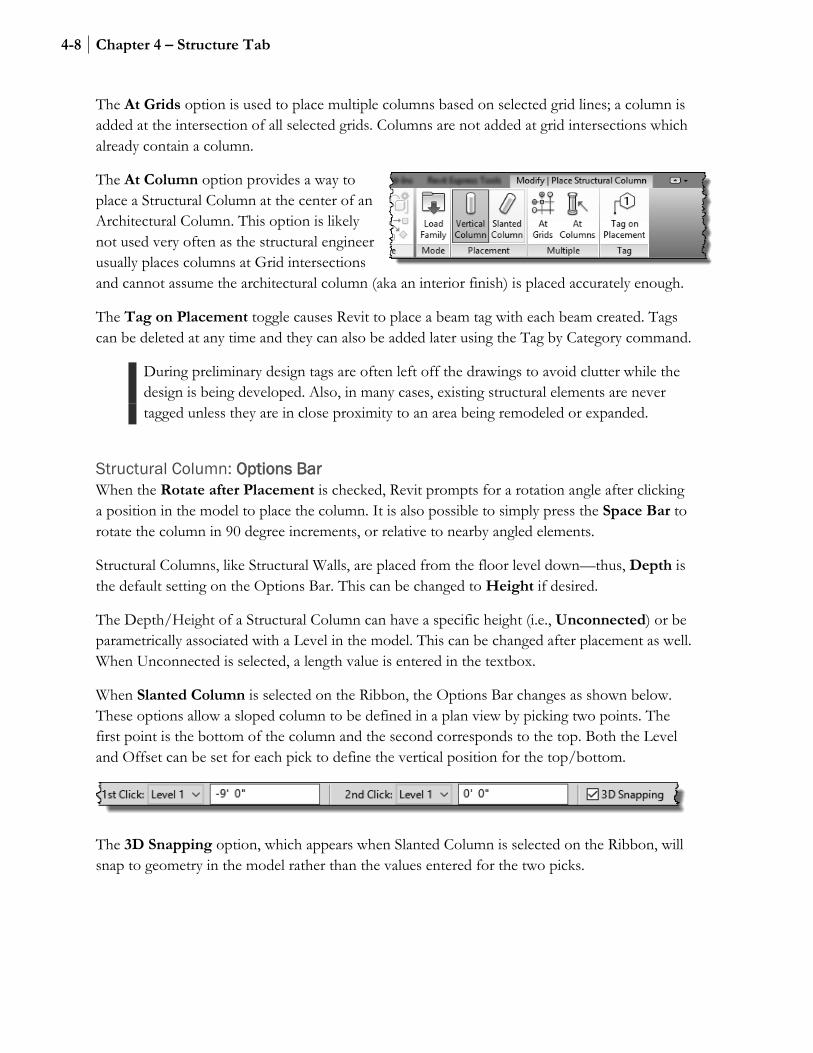
The At Column option provides a way to place a Structural Column at the center of an Architectural Column. This option is likely not used very often as the structural engineer usually places columns at Grid intersections and cannot assume the architectural column (aka an interior finish) is placed accurately enough.
The Tag on Placement toggle causes Revit to place a beam tag with each beam created. Tags can be deleted at any time and they can also be added later using the Tag by Category command.
During preliminary design tags are often left off the drawings to avoid clutter while the design is being developed. Also, in many cases, existing structural elements are never tagged unless they are in close proximity to an area being remodeled or expanded.
Structural Column: Options Bar When the Rotate after Placement is checked, Revit prompts for a rotation angle after clicking a position in the model to place the column. It is also possible to simply press the Space Bar to rotate the column in 90 degree increments, or relative to nearby angled elements.
Structural Columns, like Structural Walls, are placed from the floor level down—thus, Depth is the default setting on the Options Bar. This can be changed to Height if desired.
The Depth/Height of a Structural Column can have a specific height (i.e., Unconnected) or be parametrically associated with a Level in the model. This can be changed after placement as well. When Unconnected is selected, a length value is entered in the textbox.
When Slanted Column is selected on the Ribbon, the Options Bar changes as shown below. These options allow a sloped column to be defined in a plan view by picking two points. The first point is the bottom of the column and the second corresponds to the top. Both the Level and Offset can be set for each pick to define the vertical position for the top/bottom.
The 3D Snapping option, which appears when Slanted Column is selected on the Ribbon, will snap to geometry in the model rather than the values entered for the two picks.

Autodesk Revit 2018 Architectural Command Reference 4-9
Stru
ctur
e
Structural Column: Type Selector Available Structural Columns types, which have been previously loaded in the current project, are listed in the Type Selector. If a required size/shape is not listed, use the Load Family command. Architectural Columns are not listed in the Type Selector.
Although technically the same thing, a W12x36 beam family is not the same as a W12x36 column family. Both must be loaded into a project if that size is required for both beams and columns.
Structural Column: Properties Structural Columns have two sets of properties associated with them. The main properties are presented by default (Figure 4.1-5). The second set of properties is found by changing the Properties Filter to New Analytical Columns (Figure 4.1-6).
When Moves with Grids is selected, the column will move when placed directly on a grid. This requires the column to have a valid Column Location Mark (an Instance Property after placement)—which requires two grids to intersect. If the grids are adjusted so they no longer intersect, the columns will stop moving with the grids.
Figure 4.1-5 Structural Column Properties
Figure 4.1-6 Analytical Column Properties

4-10 Chapter 4 – Structure Tab
Structural Column: In-Canvas While placing a Structural Column, press the Space Bar to rotate it before picking a placement point. Ensure the View Range is set properly so columns and beams appear in the view. Structural plans typically have the Detail Level set to Course.
Floor: Structural Note: See Chapter 3 – Architecture Tab for detailed coverage of the Floor tool.
A structural floor is any floor, as determined by a structural engineer, which supports a load. A Structural floor is an Architectural floor with the Structural parameter checked; notice in Object Styles and Visibility/Graphic Overrides there is no Structural Floor category.
For a Floor, when the Structural parameter is checked, several additional structural parameters become available (Figure 4.1-7).
When a floor is supported by the ground, that is—a slab on grade, use a Structural Foundation Slab (see this tool later in this chapter). When the floor is being supported by other building elements, use a Structural Floor.
When using external structural analysis tools (e.g. Autodesk Robot or RISA Technologies) only Structural floors are exported and considered.
Most floors are structural floors. However, floors may be used architecturally to represent a floor finish; for example, a 1/8” thick floor positioned on top of the structural floor (which may be coming from a linked structural Revit model). This allows each room to have a separate finish apart from the main structural floor element (which would not be editable if contained within a link). TIP: These finish floors should be set to non-Room Bounding.
Because most floors are structural, all floors appear in a view, even when the view’s Discipline is set to Structural. Thus, a view Filter may need to be employed to hide any non-structural floors.
When using the Floor: Structural tool, Revit will automatically add a Span Direction Symbol to the current view. This can be deleted without loss of information. It may also be manually added to a view using the Span Direction tool on the Annotate tab.
Figure 4.1-7 Structural floor properties

Autodesk Revit 2018 Architectural Command Reference 4-11
Stru
ctur
e
Floor: Architectural Note: See Chapter 3 – Architecture Tab for detailed coverage of this tool.
Floor: Slab Edge Note: See Chapter 3 – Architecture Tab for detailed coverage of this tool.

4-12 Chapter 4 – Structure Tab
Truss The Truss command is used to create a structural floor or roof truss in a building model. A Truss is a unique family which defines a repeating pattern of three fundamental components of a truss: Top Chord, Web and Bottom Chord. The structural shape associated with each of these components can be changed to any structural framing type loaded in the current project (Figure 4.1-8).
Truss: Ribbon The Load Family option provides a convenient way to bring in additional content without needing to cancel the current command and switch to the Insert tab.
Trusses can only be straight segments; thus, there are only two Draw options: Line and Pick Lines.
Tag on Placement allows the new
Truss
1. Ribbon • Load Family • Line Segment or Pick • Tag on Placement
2. Options Bar • Placement Plane • Chain
3. Type Selector • Select Truss Type
4. Properties • Set truss Height
5. Type Properties • Edit all “Set Framing Type”
values to desired framing member 6. In-Canvas
• Pick two points to define length of truss
• FYI: An error may result if points are too close, as the truss design may not work
quic
k st
eps
Figure 4.1-8 Structural truss and its properties

Autodesk Revit 2018 Architectural Command Reference 4-13
Stru
ctur
e
truss to automatically be tagged in the current view.
Truss: Options Bar The Placement Plane drop-down defines the vertical position of the truss. In a plan view, the default setting corresponds to the level associated with the current view. All Levels and named horizontal reference planes appear in this list. In a 3D view, this list also shows grid lines to help constrain the placement of trusses.
Chain is a common option in Revit which allows continuous sequential picks without the need to re-pick the previous point to define the start point of the next element.
Truss: Type Selector Available truss types, which have been previously loaded in the current project, are listed in the Type Selector. If a required truss type is not listed, use the Load Family command on the Ribbon—or from the Insert tab. Several truss families are installed with Revit (Figure 4.1-9).
Figure 4.1-9 Structural truss families provided with Revit

4-14 Chapter 4 – Structure Tab
Truss: Properties In the Properties Palette (i.e., Instance Properties) set the Bearing Chord; options are Top and Bottom.
Truss: Type Properties The Type Properties for a truss provide a means to change the structural shape and position of the Top Chord, Web and Bottom Chord components.
Truss: In-Canvas Pick two points within the model to define the length of the truss. Picking points on a structural wall or column will create a parametric relationship and connect the structural analytical mode properly. Thus, if a wall or column is repositioned, the truss adjusts as well.
Brace A Brace is a structural framing element, which has its Structural Usage set to Other, that slopes and connects to two other structural elements (columns and/or beams) as seen in Figure 4.1-10.
Brace: Ribbon The Load Family option provides a convenient way to bring in additional content without needing to cancel the current command and switch to the Insert tab.
Braces can only be straight segments; thus, there is only one Draw option: Line.
Tag on Placement allows the new brace to automatically be tagged in the current view.
Brace: Options Bar When in a plan view, the Options Bar provides a way to define the vertical position of the Start and End of the brace. 3 D Snapping is the only option in a 3D view.
Brace
1. Ribbon • Load Family • Tag on Placement
2. Options Bar (plan view) • Start Level/offset • End Level/offset • 3D Snapping
3. Type Selector • Select Bracing/Framing Type
4. Properties • Several under Geometric Position
5. In-Canvas • Pick two points to define bracing
quic
k st
eps
Autodesk Revit 2018 Architectural Command Reference 4-15
Stru
ctur
e
Brace: Type Selector Available brace types, any Structural Framing family loaded into the current project, are listed in the Type Selector. If a required truss type is not listed, use the Load Family command on the Ribbon—or from the Insert tab.
Brace: Properties The Properties Pallet offers several settings in the Geometric Position section which control how the geometry appears within the model.
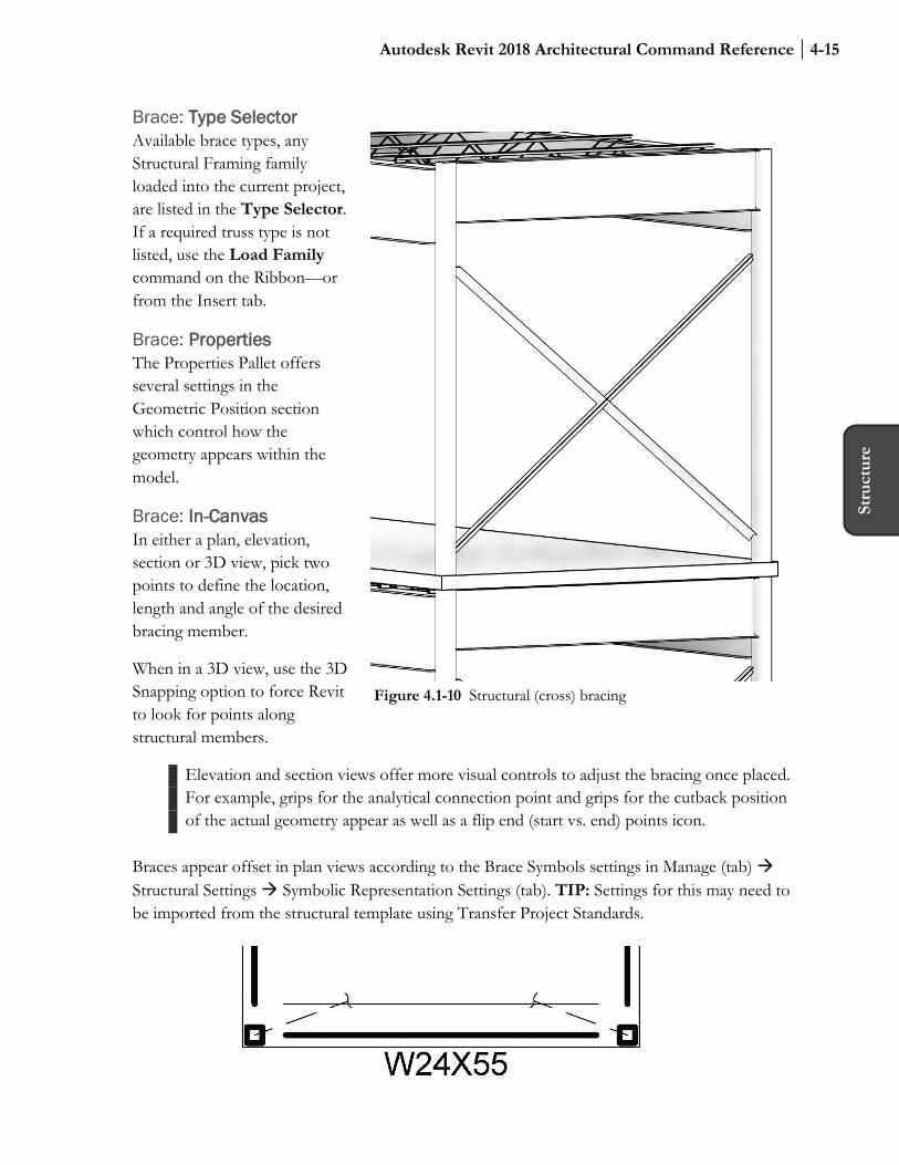
Brace: In-Canvas In either a plan, elevation, section or 3D view, pick two points to define the location, length and angle of the desired bracing member.
When in a 3D view, use the 3D Snapping option to force Revit to look for points along structural members.
Elevation and section views offer more visual controls to adjust the bracing once placed. For example, grips for the analytical connection point and grips for the cutback position of the actual geometry appear as well as a flip end (start vs. end) points icon.
Braces appear offset in plan views according to the Brace Symbols settings in Manage (tab) Structural Settings Symbolic Representation Settings (tab). TIP: Settings for this may need to be imported from the structural template using Transfer Project Standards.
Figure 4.1-10 Structural (cross) bracing

4-16 Chapter 4 – Structure Tab
Beam System
1. Ribbon • Automatic: If one or more enclosed
beams (i.e., structural bay) are visible in the current view
Automatic Beam System Sketch Beam System Tag on Placement
• Sketch: If no enclosed beam areas are visible or don’t exist
Boundary Line Beam Direction Line Segment Or Pick Line Or Pick Beam Work Plane Settings Reset System
2. Options Bar • For Automatic
Beam Type Justification Layout Rule 3D Tag Style
• For Sketch Chain Offset Radius
3. Type Selector • Select Type
4. Properties • 3D • Elevation • Layout Rule • Spacing Value • Justification • Beam Type
quic
k st
eps
Beam System The Beam System command allows us to quickly place an expanse of joists in the model without requiring the individual use of the Beam command for each instance.
Beam System: Ribbon The Ribbon offers Automatic and Sketch options to define the perimeter of the area to receive an array of framing members.
The default option is Automatic Beam System. Use this when a series of beams define an enclosed area. Otherwise switch to the Sketch options and use the Draw options to manually define the perimeter. A special Draw options in Sketch mode is Pick Beams, which places a sketch line at the center of a beam or structural wall.
Tag on Placement allows the new brace to automatically be tagged in the current view.
Beam System: Options Bar While in Automatic mode, the Options Bar offers a convenient way to set Beam Type, Justification and Layout Rule for the joists about to be placed.

Autodesk Revit 2018 Architectural Command Reference 4-17
Stru
ctur
e
If the top of the walls sloped (using Edit Profile on the wall, for example), and the bead system should follow that slope, then ensure Walls Define Slope is checked. This for either orientation relative to the wall, parallel or perpendicular framing.
When switching to Sketch mode, the Options Bar changes to this:
While in Sketch mode, to change the beam system “pattern” edit the same parameters in the Properties palette.
Beam System: Type Selector There is not much need for Types unless tracking some metadata (e.g. Cost) as all the parameters related to the geometry are instance parameters.
Beam System: Properties The Elevation parameter may be edited to ensure the bearing of the framing members aligns properly with the support elements.
Beam System: In-Canvas When hovering over a beam or structural wall, for the Automatic option, the direction and spacing of framing elements will appear (before clicking) as an aid. Thus, in this case, the Span Direction is implied as seen in the two examples below (Figure 4.1-11).
Figure 4.1-11 Defining Structural Beam System direction; hover cursor over beam

4-18 Chapter 4 – Structure Tab
Curved beams and structural walls, in plan, can be used to define the perimeter of a beam system (Figure 4.1-12). However, they cannot be the element selected as it cannot be used to infer the Span Direction of the framing in the Beam System.
Structural Settings The icon in the lower right of the Structure panel provides quick access to the Structural Settings dialog.
Figure 4.1-12 Structural Beam System with tag added

Autodesk Revit 2018 Architectural Command Reference 4-19
Stru
ctur
e
4.2 Structure tab: Connection panel Structural Connections is a new feature added in Revit 2018. Not only does this feature offer a way to show geometry to represent connections and base plates, it also offers a means to share these important decisions with structural analysis and detailing software.
Important Information About This Feature: The Autodesk provided add-in Steel Connections for Autodesk Revit 2018 64-Bit must be installed to realize the full potential of the Structural Connections feature. Also, this feature only works with certified Revit structural families. This DOES NOT include the basic content in the Revit provided templates or the content in the main Column or Beam folders. The only steel content that works with this feature is located here:
• C:\ProgramData\Autodesk\RVT 2018\Libraries\US Imperial\Structural Framing\Steel\AISC 14.1
• C:\ProgramData\Autodesk\RVT 2018\Libraries\US Imperial\Structural Columns\Steel\AISC 14.1
Connection Without the add-in mentioned above, Revit only places an analytical connection with no 3D geometry being created.
Connection: Ribbon The Ribbon only displays a grayed out Modify Parameters button. This is only available after the Connection is created.
Connection: Type Selector The options listed here are dependent on the connections loaded into the current project from the Structural Connection Settings dialog—which is accessible via the small icon in the lower right corner of the Connection panel on the Ribbon. The list of Available Connections will be empty if the required add-in mentioned above is not installed.
Connection
1. Ribbon • Modify Parameters
2. Type Selector • Select Type
3. Properties • Approval Status
4. In-Canvas • Select structural element(s); hold
Ctrl if selecting more than one. • Press Enter to complete
command. • Detail Level must be set to Fine
to see structural connections.
quic
k st
eps

4-20 Chapter 4 – Structure Tab
Connection: Properties The Approval Status allows the structural engineers to keep track of Connections they have reviewed and ones which still need work. The list of options is editable via the Structural Connection Settings dialog.
Connection: In-Canvas With the Connections command active, select the necessary structural elements and then press Enter.
The Detail Level must be set to Fine to see the connection geometry in a view. Once a connection is placed, the Modify Parameters button becomes active. Clicking it reveals a dialog specific to the connection type selected. This dialog has several categories to choose from on the left, with the remainder of the dialog showing a multitude of options for the selected category.
The image below shows the basic steps after activating the Connections command:
Figure 4.2-1 Structural Connections workflow

Autodesk Revit 2018 Architectural Command Reference 4-21
Stru
ctur
e
4.3 Structure tab: Foundation panel Revit provides a Foundation tool (or, perhaps better described as a Footing) to model the building element which transfers the structural load from a wall or column to the earth. This element is often larger than the wall or column to help spread the load—this larger size is determined by a geotechnical engineer based on soil analysis at the project site.
Isolated Foundation (i.e., Footing) This command places a structural element intended to support a structural column. “Isolated” simply means it may have earth all around it and may not be in contact with any other foundations/footings. When associated with a column, the foundation automatically aligns with the bottom of the column and will maintain that relationship if modified in any way.
Isolated: Ribbon The Load Family option provides a convenient way to bring in additional content without needing to cancel the current command and switch to the Insert tab.
If the Isolated Footing is unique and there is no family loaded in the project, we can click the Model In-place command to quickly switch gears and create the desired geometry directly in the project.
Isolated Foundation
1. Ribbon • Multiple; at Grids • Multiple; at Columns
2. Options Bar • Rotate after Placement • Level (3D view only)
3. Type Selector • Select Type
4. Properties • Level/Offset • Structural Material • Enable Analytical Model
5. In-Canvas • Spacebar to rotate
quic
k st
eps
Figure 4.3-1 Isolated foundation added at structural column

4-22 Chapter 4 – Structure Tab
Revit offers two options on the Ribbon to quickly place multiple Isolated Footings: At Grids and At Columns.
Using the At Grids option requires two or more Grids to be selected. A temporary representation of the Isolated Foundation appears. Clicking the Green Checkmark completes the task and created the elements. Changes to the Grid locations causes the Isolated Foundations to update as seen in Figure 4.3-2; notice Grid 5 has been repositioned. The foundations also moved—even the one along the angled grid.
The At Column option is preferred in that the Isolated Foundation becomes associated with the element it actually supports. If the column moves, the Isolated Foundation updates accordingly. Of course, this option requires that columns exist first.
Isolated: Options Bar When the Rotate after Placement is checked, Revit prompts for a rotation angle after clicking a position in the model to place the element. It is also possible to simply press the Space Bar to rotate the element in 90 degree increments, or relative to nearby angled elements.
While in a 3D view, the Options Bar also provides an option to select the Level to host the placed element.
Isolated: Type Selector Available Isolated Foundation types, which have been previously loaded in the current project, are listed in the Type Selector. If a required size/shape is not listed, use the Load Family command.
Figure 4.3-2 Isolated foundations added at grid intersections update automatically
Autodesk Revit 2018 Architectural Command Reference 4-23
Stru
ctur
e
Isolated: Properties If the Isolated Foundation is not associated with the bottom of a column, the Level needs to be selected via the Properties Palette (i.e. Instance Properties). The only options for the Level parameter are Levels that exist in the project—named Reference Planes are not accessible here. If there is a lot of variation in elevation, for a sloped site as an example, use the Height Offset from Level parameter to avoid adding an excessive amount of Levels.
The Structural Material is used to specify which Revit material is assigned to the element. This determines how the element looks in the model and renderings as well as what the physical properties are when sent to a structural analysis program.
Moves with Grids only applies when an element is placed directly on a Grid—not necessarily at a Grid intersection.
When Enable Analytical Model is checked, Revit understands this element should be included in any structural analysis calculations. For existing elements in a remodel or addition, which is not being modified in any direct or in-direct way, then this option can be unchecked.
Isolated: In-Canvas Switch to the plan view associated with the Level you need to associate the element with. If a view or level does not exist, switch to the closest level and then specify the Level or Offset via Properties.
Spacebar to rotate the element before placement.
When using one of the Multiple options, drag a window or use Ctrl to select multiple columns/grids.
4-24 Chapter 4 – Structure Tab
Wall Foundation (i.e., Footing) A Wall Foundation attaches to the bottom of a wall, structural or non-structural. If the wall is adjusted or moved, the element is updated accordingly.
This command is dependent on walls already existing in the model. Also, if the host wall is deleted, the wall foundation is also deleted—just like doors and windows in the same wall.
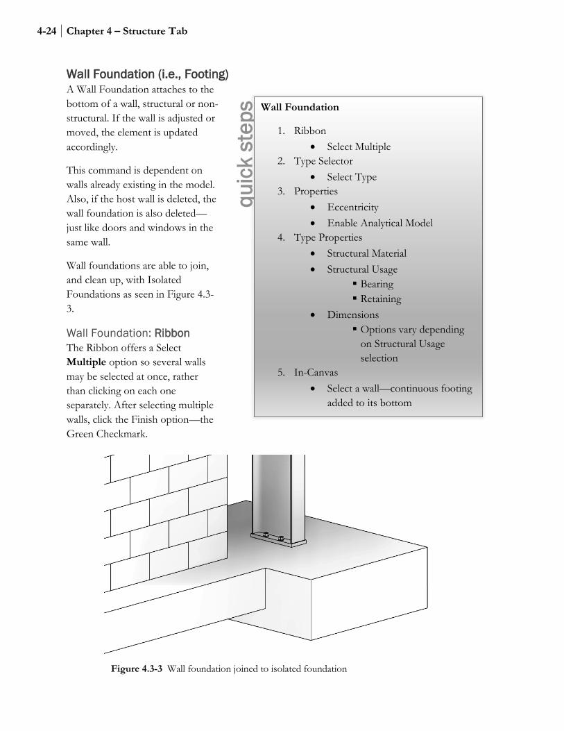
Wall foundations are able to join, and clean up, with Isolated Foundations as seen in Figure 4.3-3.
Wall Foundation: Ribbon The Ribbon offers a Select Multiple option so several walls may be selected at once, rather than clicking on each one separately. After selecting multiple walls, click the Finish option—the Green Checkmark.
Wall Foundation
1. Ribbon • Select Multiple
2. Type Selector • Select Type
3. Properties • Eccentricity • Enable Analytical Model
4. Type Properties • Structural Material • Structural Usage
Bearing Retaining
• Dimensions Options vary depending
on Structural Usage selection
5. In-Canvas • Select a wall—continuous footing
added to its bottom
quic
k st
eps
Figure 4.3-3 Wall foundation joined to isolated foundation

Autodesk Revit 2018 Architectural Command Reference 4-25
Stru
ctur
e
Wall Foundation: Type Selector Available Wall Foundation types, which have been previously defined in the current project, are listed in the Type Selector. If a required size is not listed, use the Edit Type Duplicate option. A Wall Foundation is a system family, meaning it can only exist within the context of a project, similar to walls. Thus, there are no families (rfa files) to be loaded.
Wall Foundation: Properties By default, the Wall Foundation is centered on the overall wall thickness. Use the Eccentricity parameter to reposition the Wall Foundation relative to the center of the wall; both positive and negative numbers are allowed.
When Enable Analytical Model is checked, Revit understands this element should be included in any structural analysis calculations. For existing elements in a remodel or addition, which is not being modified in any direct or in-direct way, this option can be unchecked.
Wall Foundation: Type Properties The Structural Material is used to specify which Revit material is assigned to the element. This determines how the element looks in the model and renderings as well as what the physical properties are when sent to a structural analysis program.
Changing the Structural Usage option affects which dimensions appear as described below. The two options are Bearing and Retaining.
When the Structural Usage is set to Bearing, the Dimension options are (Fig. 4.3-4):
• Width • Foundation Thickness • Default End Extension Length
When the Structural Usage is set to Retaining, the Dimension options are (Fig. 4.3-5):
• Width (read only - instance) • Toe Length • Heel Length • Foundation Thickness • Default End Extension Length
Figure 4.3-6 shows a section with a “bearing” wall foundation on the left and a
Figure 4.3-4 Wall foundation (bearing) dimensions
Figure 4.3-5 Wall foundation (retaining) dimensions

4-26 Chapter 4 – Structure Tab
“retaining” example on the right. Notice, wall foundations are aligned from the top.
Wall Foundation: In-Canvas With the Wall Foundation command active, simply select individual walls, or use the Select Multiple option to select several at once.
Once created, in a section view, use the Cut Profile command on the View tab to add a keyway as shown in the image below (Figure 4.3-7). Keep in mind this is a view specific override and does not change the 3D geometry.
Figure 4.3-6 Wall foundations; Bearing (left) and Retaining (right)
Figure 4.3-7 Cut Profile applied to Wall and Wall Foundation
Autodesk Revit 2018 Architectural Command Reference 4-27
Stru
ctur
e
Structural Foundations: Slab The Structural Foundation Slab is primarily meant to model a slab on grade. This tool is exactly like the Floor and Structural Floor commands, but with the added convenience of being sorted into a separate category, Wall Foundations.
See Walls and Structural Walls for more information.
Slab Foundation: Ribbon When sketching a slab, there are three “pick” options: Pick Lines, Pick Walls and Pick Supports. The Pick Supports option can be walls or beams.
Slab Foundation: Options Bar When Draw is set to Pick Walls or Supports, the Extend into wall (to core) option appears. When this is checked, the slab extends to the edge of the layers, within the wall, defined as the Core, or structural, part of the wall.
Slab Foundation: Type Selector Available Foundation Slab types, which have been previously defined in the current project, are listed in the Type Selector. If a required size is not listed, use the Edit Type Duplicate and then Edit Structure. A Foundation Slab is a system family, meaning it can only exist within the context of a project, similar to walls. Thus, there are no families (rfa files) to be loaded.
Slab Foundation: In-Canvas Sketch the perimeter of the slab—the sketch cannot have gaps or crossing lines. Any closed loops within the outer perimeter become holes in the slab.
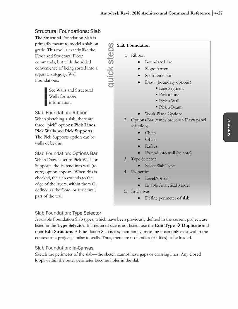
Slab Foundation
1. Ribbon • Boundary Line • Slope Arrow • Span Direction • Draw (boundary options)
Line Segment Pick a Line Pick a Wall Pick a Beam
• Work Plane Options 2. Options Bar (varies based on Draw panel
selection) • Chain • Offset • Radius • Extend into wall (to core)
3. Type Selector • Select Slab Type
4. Properties • Level/Offset • Enable Analytical Model
5. In-Canvas • Define perimeter of slab
quic
k st
eps

4-28 Chapter 4 – Structure Tab
Floor: Slab Edge Note: See Chapter 3 – Architecture Tab for detailed coverage of this tool.
4.4 Structural tab: Reinforcement These tools are not covered due to the architectural focus of this book.
4.5 Remaining Structural tab Panels See Chapter 3 – Architectural tab for detailed coverage of the remaining tools on the structural tab. These tools are useful to both the architectural and structural discipline and are therefore provided on their respective tabs for convenience.