autocad 2002 exercise guide ch2
TRANSCRIPT
8/3/2019 AutoCAD 2002 Exercise Guide Ch2
http://slidepdf.com/reader/full/autocad-2002-exercise-guide-ch2 1/7
EXERCISE BOOK for AUTOCAD 2002
Contents
Basic Commands
Basic Drawing & Editing Commands Drawing Tools (OSNAP & OTRACK)
Dimensioning & Tolerancing
More Drawing & Editing Commands
Layer & Block Commands
Producing Drawings – Multiview, Sectional, Auxilliary & Assembly
Isometric Drawings
3D in AutoCAD
Using Layout & Documentation
Chapter Basic Drawing & Editing Commands
Terminology
Click or Left Click: Press (once) and release left mouse button (LMB).Right Click: Press and release right mouse button (RMB).Double Click: Commonly referred to clicking LMB twice.Click and drag: Press (not release) left mouse button, and move the mouse. Theleft mouse button is released to finish the command.Menu:
8/3/2019 AutoCAD 2002 Exercise Guide Ch2
http://slidepdf.com/reader/full/autocad-2002-exercise-guide-ch2 2/7
AutoCAD 2002 Exercise Book
2002 Adzly Anuar Dept. of Mechanical Engineering Universiti Tenaga Nasional
-18-
Basic Drawing & Editing Commands
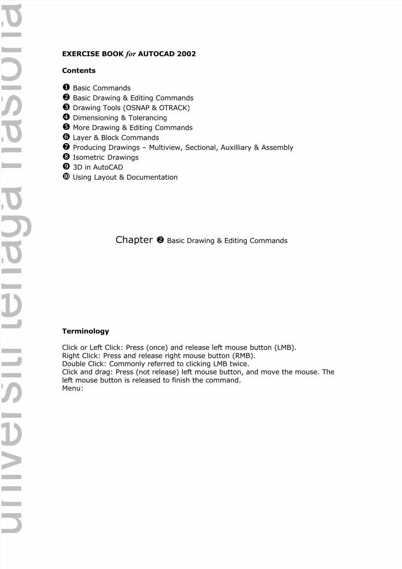
Creating single line text.1) Start AutoCAD 2002. Create new drawing. You could use the default
drawing limits or set to 400 by 300. Activate the grid.2) Select from menu Draw > Text > Single line text
Or type text in the command prompt box.
3) Enter the values accordingly:
Figure 2-1
4) You should obtain the text similar to Figure 2-1.
Produce the following text, as shown in Figure 2-2 below.
Figure 2-2
2.1 Creating text using TEXT and MTEXT command
Current text height, 50
Start point (100,100)Change text height to 10
Zero rotation (horizontal)
Text – first line
Text – second linePress {enter} to end the command
Start point (100,100)
(0,0)
Height: 10
8/3/2019 AutoCAD 2002 Exercise Guide Ch2
http://slidepdf.com/reader/full/autocad-2002-exercise-guide-ch2 3/7
AutoCAD 2002 Exercise Book
2002 Adzly Anuar Dept. of Mechanical Engineering Universiti Tenaga Nasional
-19-
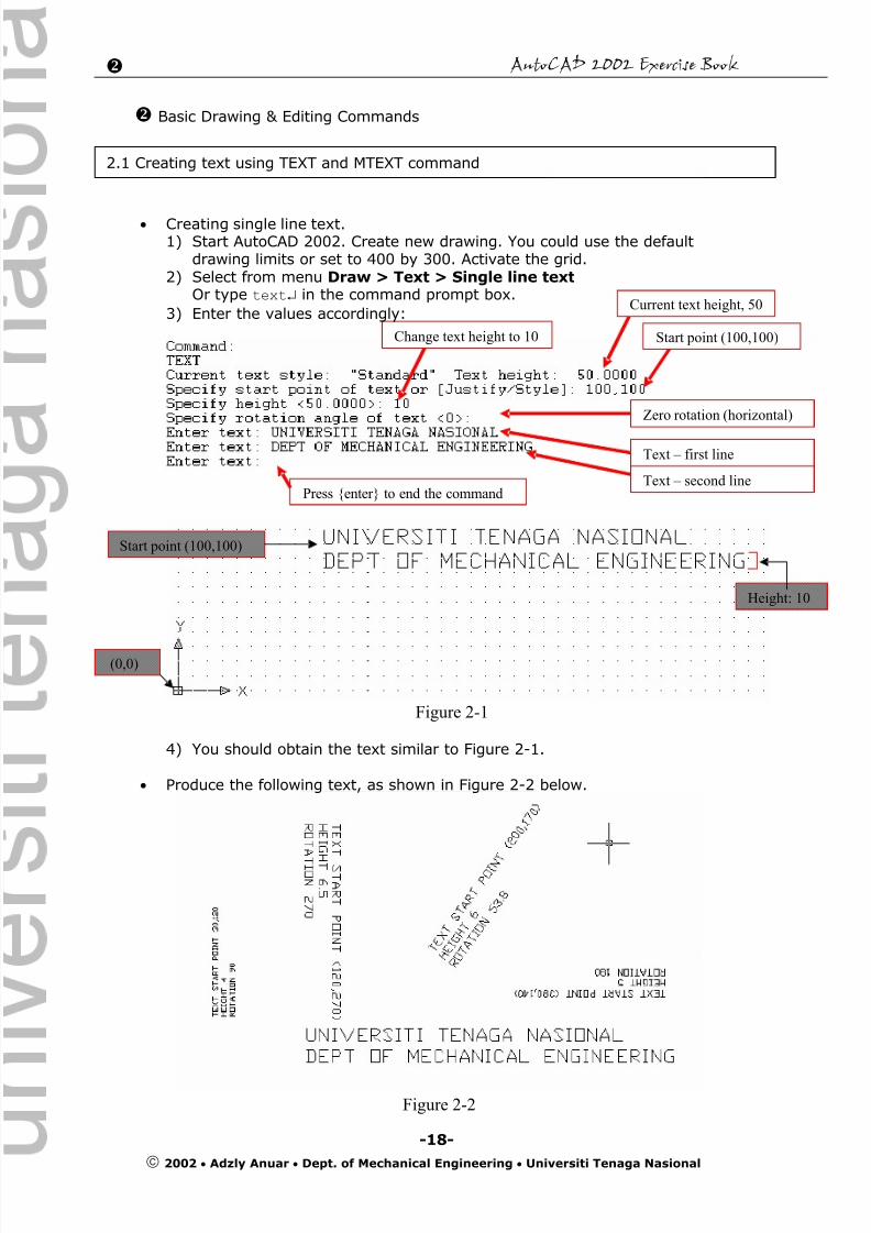
Creating multiline text (MTEXT).1) Click on multiline text icon, or type in MTEXT in command prompt area,
or select from menu Draw > Text > Multiline Text… 2) Specify first corner: 40,1503) Specify opposite corner: 140,200
Figure 2-3
4) Multiline Text Editor window will be shown. (Figure 2-4)5) Type in the text;
DEPARTMENT OF MECHANICAL ENGINEERINGUNIVERSITI TENAGA NASIONALYou should notice that the words are adjusted (pushed to the next line)according to the width of the box (in this case, width is 100). All thewords are drawn inside the box, and considered as one element.
Figure 2-4
6) Click button OK. You should obtain text similar to Figure 2-5.
Figure 2-5
7) The size of the text box can be changed. Click on the text. Click on theblue square at the lower right hand corner. Move the mouse. Try clickingon other corners and move the mouse.
(a) Click on the text (b) Click on the corner, move the mouseFigure 2-6
Note:Instead of typing the
coordinates, mouseclick could be used tospecify the corners.
1st corner
(40,150)
Opposite corner
(140,200)
(40,200) (140,200)

8/3/2019 AutoCAD 2002 Exercise Guide Ch2
http://slidepdf.com/reader/full/autocad-2002-exercise-guide-ch2 4/7
AutoCAD 2002 Exercise Book
2002 Adzly Anuar Dept. of Mechanical Engineering Universiti Tenaga Nasional
-20-
Exercise:Create the text shown in Figure 2-7 using TEXT and/or MTEXT command.
Figure 2-7
8/3/2019 AutoCAD 2002 Exercise Guide Ch2
http://slidepdf.com/reader/full/autocad-2002-exercise-guide-ch2 5/7
AutoCAD 2002 Exercise Book
2002 Adzly Anuar Dept. of Mechanical Engineering Universiti Tenaga Nasional
-21-
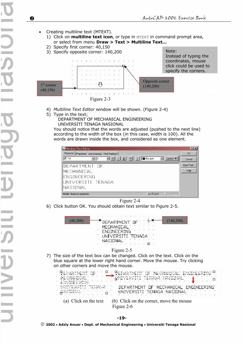
Draw the following object. Set the drawing limits to 300 by 250. Activate Gridand Snap. Set the grid spacing to be 10 and snap spacing to be 5. Do not
dimension and draw the center/hidden lines at this moment. Save thedrawing as Exe2_2.dwg
Figure 2-8
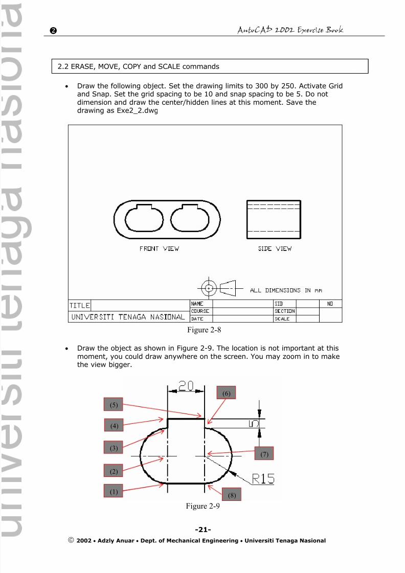
Draw the object as shown in Figure 2-9. The location is not important at thismoment, you could draw anywhere on the screen. You may zoom in to makethe view bigger.
Figure 2-9
2.2 ERASE, MOVE, COPY and SCALE commands
(1)
(2)
(3)
(4)
(5)
(6)
(7)
(8)
8/3/2019 AutoCAD 2002 Exercise Guide Ch2
http://slidepdf.com/reader/full/autocad-2002-exercise-guide-ch2 6/7
AutoCAD 2002 Exercise Book
2002 Adzly Anuar Dept. of Mechanical Engineering Universiti Tenaga Nasional
-22-
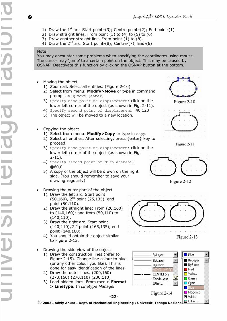
1) Draw the 1st arc. Start point–(3); Centre point–(2); End point-(1)2) Draw straight lines. From point (3) to (4) to (5) to (6).3) Draw another straight line. From point (1) to (8).4) Draw the 2nd arc. Start point-(8); Centre-(7); End-(6)
Moving the object1) Zoom all. Select all entities. (Figure 2-10)2) Select from menu: Modify>Move or type in command
prompt area; move {enter}
3) Specify base point or displacement: click on the
lower left corner of the object (as shown in Fig. 2-11).4) Specify second point of displacement: 40,120
5) The object will be moved to a new location.
Copying the object1) Select from menu: Modify>Copy or type in copy.
2) Select all entities. After selecting, press {enter} key toproceed.
3) Specify base point or displacement: click on the
lower left corner of the object (as shown in Fig.2-11).
4) Specify second point of displacement: @60,05) A copy of the object will be drawn on the rightside. (You should remember to save yourdrawing regularly)
Drawing the outer part of the object1) Draw the left arc. Start point
(50,160), 2nd point (25,135), endpoint (50,110).
2) Draw the straight line: From (20,160)to (140,160); and from (50,110) to(140,110).
3) Draw the right arc. Start point(140,110), 2nd point (165,135), endpoint (140,160).
4) You should obtain the object similarto Figure 2-13.
Drawing the side view of the object1) Draw the construction lines (refer to
Figure 2-15). Change line colour to blue(or any other colour you like). This isdone for easy identification of the lines.
2) Draw the outer lines. (200,160)(270,160) (270,110) (200,110)
3) Load hidden lines. From menu: Format> Linetype. In Linetype Manager
Note:
You may encounter some problems when specifying the coordinates using mouse.The cursor may ‘jump’ to a certain point on the object. This may be caused byOSNAP. Deactivate this function by clicking the OSNAP button at the bottom.
Figure 2-10
Figure 2-11
Figure 2-12
Figure 2-13
Figure 2-14
8/3/2019 AutoCAD 2002 Exercise Guide Ch2
http://slidepdf.com/reader/full/autocad-2002-exercise-guide-ch2 7/7
AutoCAD 2002 Exercise Book
2002 Adzly Anuar Dept. of Mechanical Engineering Universiti Tenaga Nasional
-23-
window, click on Load… button. Click on the linetypeACAD_ISO02W100 (the first in the list). Then click OK button. InLinetype Manager window, click OK button.
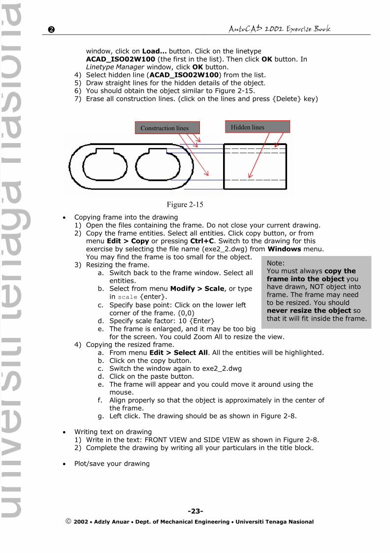
4) Select hidden line (ACAD_ISO02W100) from the list.5) Draw straight lines for the hidden details of the object.6) You should obtain the object similar to Figure 2-15.
7) Erase all construction lines. (click on the lines and press {Delete} key)
Copying frame into the drawing1) Open the files containing the frame. Do not close your current drawing.2) Copy the frame entities. Select all entities. Click copy button, or from
menu Edit > Copy or pressing Ctrl+C. Switch to the drawing for thisexercise by selecting the file name (exe2_2.dwg) from Windows menu.You may find the frame is too small for the object.
3) Resizing the frame.a. Switch back to the frame window. Select all
entities.
b. Select from menu Modify > Scale, or typein scale {enter}.
c. Specify base point: Click on the lower leftcorner of the frame. (0,0)
d. Specify scale factor: 10 {Enter}e. The frame is enlarged, and it may be too big
for the screen. You could Zoom All to resize the view.4) Copying the resized frame.
a. From menu Edit > Select All. All the entities will be highlighted.b. Click on the copy button.c. Switch the window again to exe2_2.dwgd. Click on the paste button.
e.
The frame will appear and you could move it around using themouse.f. Align properly so that the object is approximately in the center of
the frame.g. Left click. The drawing should be as shown in Figure 2-8.
Writing text on drawing1) Write in the text: FRONT VIEW and SIDE VIEW as shown in Figure 2-8.2) Complete the drawing by writing all your particulars in the title block.
Plot/save your drawing
Construction lines
Figure 2-15
Hidden lines
Note:You must always copy theframe into the object youhave drawn, NOT object intoframe. The frame may needto be resized. You shouldnever resize the object sothat it will fit inside the frame.