audio/video control receiver rx-664vbk - jvc...
TRANSCRIPT
For Customer Use:Enter below the Model No. and Serial No. which are located either on the rear, bottom or side of the cabinet. Retain this information for future reference.
Model No.
Serial No.
LET0119-001B[J]
INSTRUCTIONS
RX-664VBKAUDIO/VIDEO CONTROL RECEIVER
RX-664V AUDIO/VIDEO CONTROL RECEIVER
STANDBY
POWER
PHONES SPEAKERS
MASTER VOLUME
– +
TUNER/BAND PRESET SEA SOURCE SURROUND ADJUST
ONE TOUCH OPERATION
SETTING
MEMORY
1 2
_ON —OFF
DVD MULTI
CATV/SAT
ONE TOUCH OPERATION
TV/VIDEO
TV
CATV CONTROLCD-DISC
SOUND CONTROL
VCR AUDIO
CENTER REAR (L)
CHTV VOLUME
100+ RETURN/ENTER
321
654
98
0
7/P
+10 10
PHONO
CD
VCR
MUTING
VOLUME
DVD MULTI
TAPE
DVD
POWER
TUNER/
BAND
TV SOUND
RM-SR664U REMOTE CONTROL
DAP MODE 3D-PHONIC SURROUND
EFFECT DELAY TEST
SEA MODE SEA PRESET MENU
– REAR•R +
SLEEP
RX-664VBK(J)_0119-001B.Cover 98.1.6, 11:20 AM1
G-1
Warnings, Cautions and Others
Caution –– POWER switch!Disconnect the mains plug to shut the power off completely. ThePOWER switch in any position does not disconnect the mains line.The power can be remote controlled.
CAUTION: TO REDUCE THE RISK OF ELECTRIC SHOCK. DO NOT REMOVE COVER (OR BACK) NO USER SERVICEABLE PARTS INSIDE. REFER SERVICING TO QUALIFIED SERVICE PERSONNEL.
RISK OF ELECTRIC SHOCK DO NOT OPEN
The lightning flash with arrowhead symbol, within an equilateral triangle is intended to alert the user to the presence of uninsulated "dangerous voltage" within the product's enclosure that may be of sufficient magnitude to constitute a risk of electric shock to persons. The exclamation point within an equilateral triangle is intended to alert the user to the presence of important operating and maintenance (servicing) instructions in the literature accompanying the appliance.
CAUTION
WARNING: TO REDUCE THE RISK OF FIRE OR ELECTRIC SHOCK, DO NOT EXPOSE THIS APPLIANCE TO RAIN OR MOISTURE.
CAUTIONTo reduce the risk of electrical shocks, fire, etc.:1. Do not remove screws, covers or cabinet.2. Do not expose this appliance to rain or moisture.
RX-664VBK(J)_0119-001B.G-page 98.1.6, 11:21 AM1
G-2
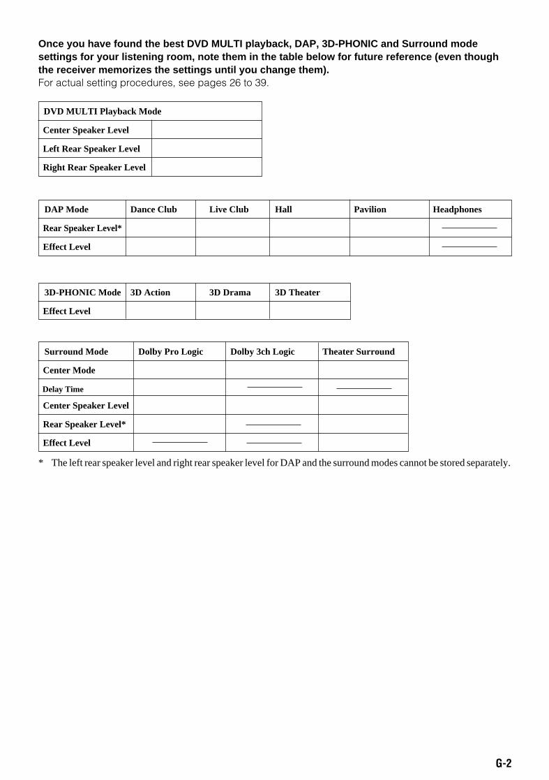
Once you have found the best DVD MULTI playback, DAP, 3D-PHONIC and Surround modesettings for your listening room, note them in the table below for future reference (even thoughthe receiver memorizes the settings until you change them).For actual setting procedures, see pages 26 to 39.
DVD MULTI Playback Mode
Center Speaker Level
Left Rear Speaker Level
Right Rear Speaker Level
DAP Mode Dance Club Live Club Hall Pavilion Headphones
Rear Speaker Level*
Effect Level
Surround Mode Dolby Pro Logic Dolby 3ch Logic Theater Surround
Center Mode
Delay Time
Center Speaker Level
Rear Speaker Level*
Effect Level
3D-PHONIC Mode 3D Action 3D Drama 3D Theater
Effect Level
* The left rear speaker level and right rear speaker level for DAP and the surround modes cannot be stored separately.
RX-664VBK(J)_0119-001B.G-page 98.1.6, 11:21 AM2
1
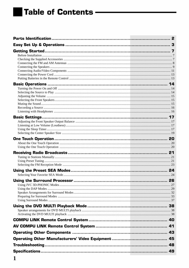
Table of Contents
Parts Identification...................................................................................... 2
Easy Set Up & Operations ............................................................................ 3
Getting Started........................................................................................... 7Before Installation................................................................................................................................................................... 7Checking the Supplied Accessories ........................................................................................................................................ 7Connecting the FM and AM Antennas ................................................................................................................................... 8Connecting the Speakers ......................................................................................................................................................... 9Connecting Audio/Video Components ................................................................................................................................. 11Connecting the Power Cord .................................................................................................................................................. 13Putting Batteries in the Remote Control ............................................................................................................................... 13
Basic Operations ....................................................................................... 14Turning the Power On and Off ............................................................................................................................................. 14Selecting the Source to Play ................................................................................................................................................. 14Adjusting the Volume ........................................................................................................................................................... 15Selecting the Front Speakers................................................................................................................................................. 15Muting the Sound.................................................................................................................................................................. 15Recording a Source ............................................................................................................................................................... 16Listening with Headphones .................................................................................................................................................. 16
Basic Settings........................................................................................... 17Adjusting the Front Speaker Output Balance ....................................................................................................................... 17Listening at Low Volume (Loudness) ................................................................................................................................... 17Using the Sleep Timer ........................................................................................................................................................... 17Selecting the Center Speaker Size ........................................................................................................................................ 19
One Touch Operation .................................................................................. 20About the One Touch Operation ........................................................................................................................................... 20Using the One Touch Operation ........................................................................................................................................... 20
Receiving Radio Broadcasts ........................................................................ 21Tuning in Stations Manually ................................................................................................................................................. 21Using Preset Tuning .............................................................................................................................................................. 21Selecting the FM Reception Mode ....................................................................................................................................... 23
Using the Preset SEA Modes...................................................................... 24Selecting Your Favorite SEA Mode ...................................................................................................................................... 24
Using the Surround Processor .................................................................... 26Using JVC 3D-PHONIC Modes ........................................................................................................................................... 27Using the DAP Modes .......................................................................................................................................................... 29Speaker Arrangements for Surround Modes ......................................................................................................................... 32Preparing for Surround Modes ............................................................................................................................................. 33Using Surround Modes ......................................................................................................................................................... 37
Using the DVD MULTI Playback Mode .......................................................... 38Speaker arrangements for DVD MULTI playback ............................................................................................................... 38Activating the DVD MULTI playback ................................................................................................................................. 38
COMPU LINK Remote Control System ......................................................... 40
AV COMPU LINK Remote Control System .................................................... 41
Operating Other Components ..................................................................... 43
Operating Other Manufacturers’ Video Equipment ........................................ 45
Troubleshooting......................................................................................... 48
Specifications............................................................................................ 49
RX-664VBK(J)_0119-001B_En.01-23 98.1.6, 11:26 AM1
2
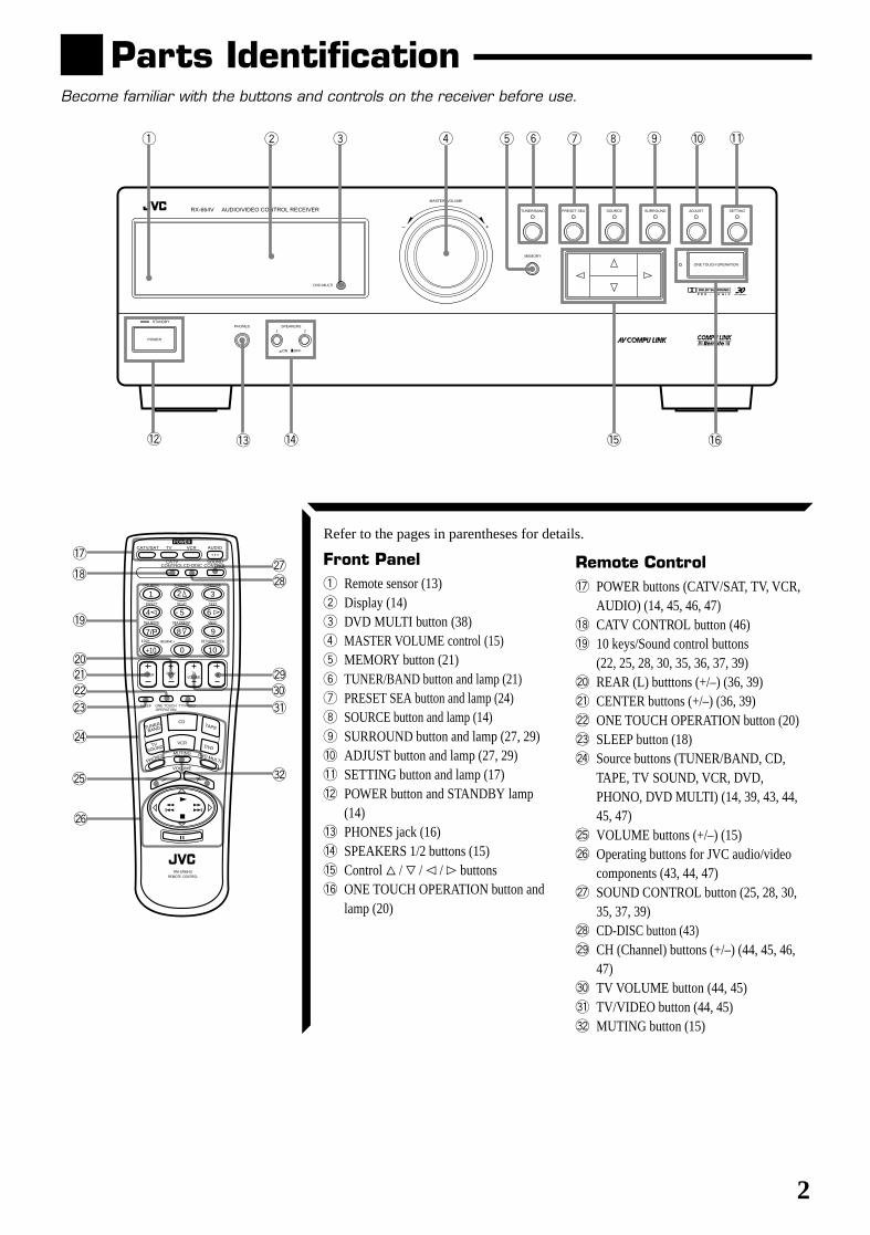
Parts IdentificationBecome familiar with the buttons and controls on the receiver before use.
Refer to the pages in parentheses for details.
Front Panel1 Remote sensor (13)2 Display (14)3 DVD MULTI button (38)4 MASTER VOLUME control (15)5 MEMORY button (21)6 TUNER/BAND button and lamp (21)7 PRESET SEA button and lamp (24)8 SOURCE button and lamp (14)9 SURROUND button and lamp (27, 29)0 ADJUST button and lamp (27, 29)- SETTING button and lamp (17)= POWER button and STANDBY lamp
(14)~ PHONES jack (16)! SPEAKERS 1/2 buttons (15)@ Control % / fi / @ / # buttons# ONE TOUCH OPERATION button and
lamp (20)
Remote Control$ POWER buttons (CATV/SAT, TV, VCR,
AUDIO) (14, 45, 46, 47)% CATV CONTROL button (46)^ 10 keys/Sound control buttons
(22, 25, 28, 30, 35, 36, 37, 39)& REAR (L) butttons (+/–) (36, 39)* CENTER buttons (+/–) (36, 39)( ONE TOUCH OPERATION button (20)) SLEEP button (18)_ Source buttons (TUNER/BAND, CD,
TAPE, TV SOUND, VCR, DVD,PHONO, DVD MULTI) (14, 39, 43, 44,45, 47)
+ VOLUME buttons (+/–) (15)¡ Operating buttons for JVC audio/video
components (43, 44, 47)™ SOUND CONTROL button (25, 28, 30,
35, 37, 39)£ CD-DISC button (43)¢ CH (Channel) buttons (+/–) (44, 45, 46,
47)∞ TV VOLUME button (44, 45)§ TV/VIDEO button (44, 45)¶ MUTING button (15)
1 4 6
!
CATV/SAT
TV/VIDEO
TV
CATV CONTROLCD-DISC
SOUND CONTROL
VCR AUDIO
CENTER REAR (L)
100+ RETURN/ENTER
321
654
98
0
7/P
+10 10
CD
VCR
MUTING DVD MULTI
TAPE
DVD
POWER
TUNER/
BAND
TV SOUND
RM-SR664U REMOTE CONTROL
TV VOLUME
CH
ONE TOUCH OPERATION
PHONO
VOLUME
DAP MODE 3D-PHONIC SURROUND
– REAR•R +
EFFECT DELAY TEST
SEA MODE SEA PRESET MENU
SLEEP
$
%
^
&*(
)
_
+
¡
™£
¢∞
§
¶
~ @
RX-664V AUDIO/VIDEO CONTROL RECEIVER
STANDBY
POWER
PHONES SPEAKERS
MASTER VOLUME
– +
TUNER/BAND PRESET SEA SOURCE SURROUND ADJUST
ONE TOUCH OPERATION
SETTING
MEMORY
1 2
_ON —OFF
DVD MULTI
-98
#=
07532
RX-664VBK(J)_0119-001B_En.01-23 98.1.6, 11:26 AM2
3
AM LOOP
ANTENNA
COMPU LINK-3 (SYNCHRO)
FRONT SPEAKERS
FM
FM 75
AM EXT
OUT (REC)
IN (PLAY)
OUT (REC)
IN (PLAY)
GND
GND
DVD
OUT (REC)
MONITOR OUT
IN (PLAY)
RIGHT LEFT
RIGHT LEFT
+ +
– –
+
1
2
1
2
– – +
+ – – +
PHONO CD TAPE TV SOUND
L
R
SUBWOOFER OUT REAR
SPEAKERS
FRONT CENTER
SUBWOOFER
REAR
LEFT
RIGHT
VIDEO
VCRCENTER
SPEAKER
TV
AV COMPU LINK
L
R
DVD
AUDIO
LEFT
RIGHT
OUT
VIDEO
AUDIOL
AUDIOR
INANTENNAIN OUT
RX-664V AUDIO/VIDEO CONTROL RECEIVER
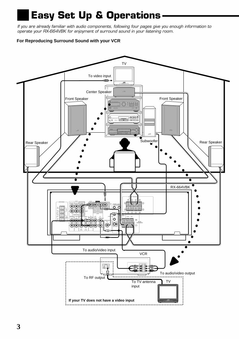
Easy Set Up & OperationsIf you are already familiar with audio components, following four pages give you enough information tooperate your RX-664VBK for enjoyment of surround sound in your listening room.
Center Speaker
For Reproducing Surround Sound with your VCR
TV
To video input
Rear SpeakerSubwoofer
Front Speaker
To audio/video input
To RF output
If your TV does not have a video input
To TV antennainput
TV
To audio/video output
VCR
RX-664VBK
Rear Speaker
Front Speaker
RX-664VBK(J)_0119-001B_En.01-23 98.1.6, 11:26 AM3
4
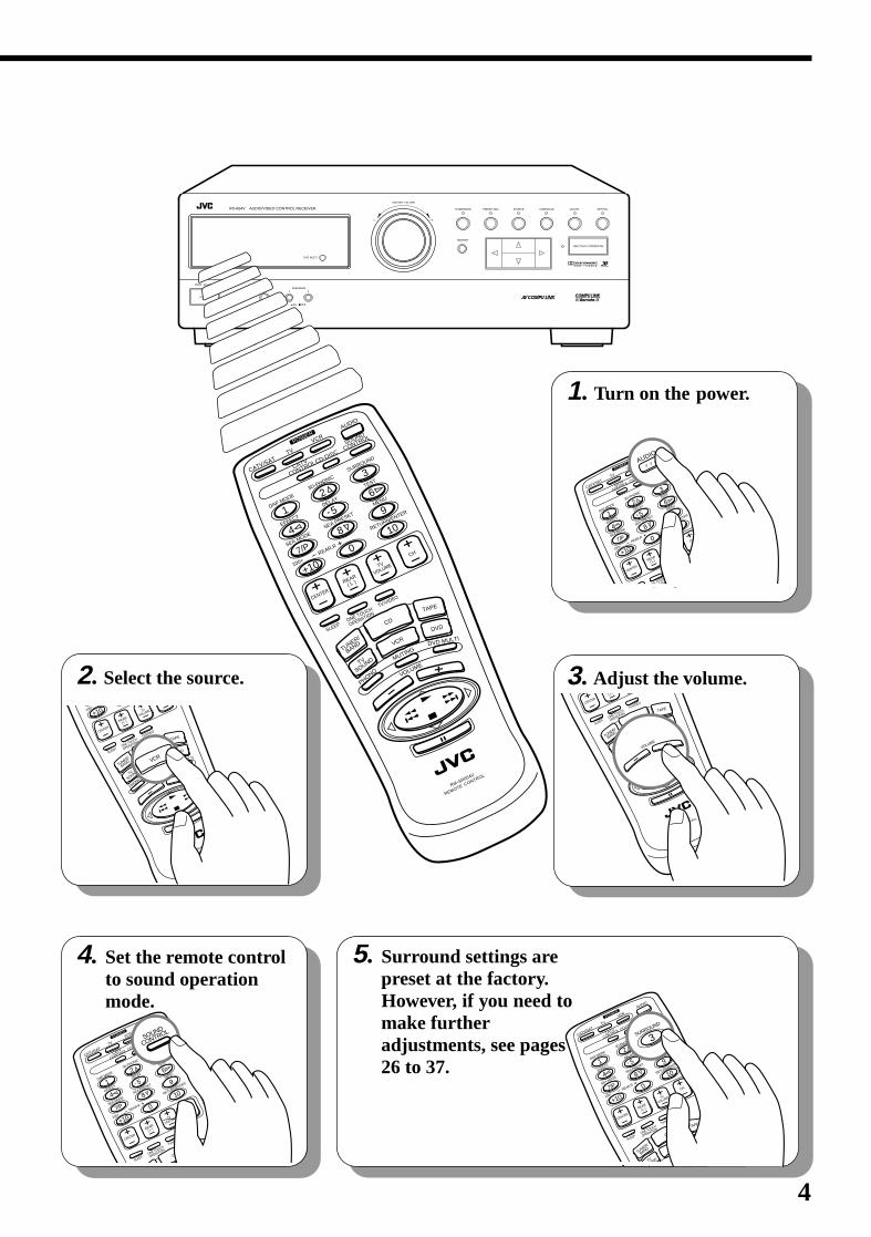
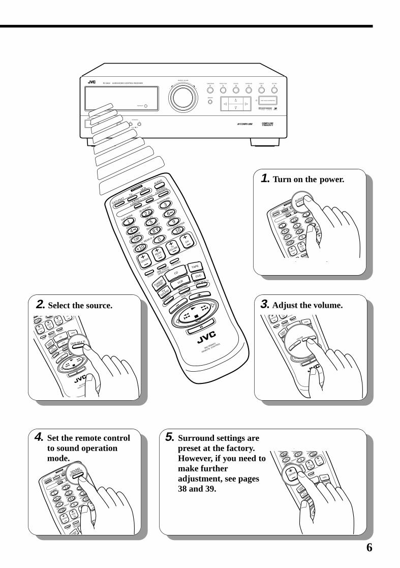
4. Set the remote controlto sound operationmode.
2. Select the source. 3. Adjust the volume.
1. Turn on the power.
5. Surround settings arepreset at the factory.However, if you need tomake furtheradjustments, see pages26 to 37.
RX-664V AUDIO/VIDEO CONTROL RECEIVER
STANDBY
POWER
PHONES SPEAKERS
MASTER VOLUME
– +
TUNER/BAND PRESET SEA SOURCE SURROUND ADJUST
ONE TOUCH OPERATION
SETTING
MEMORY
1 2
_ON —OFF
DVD MULTI
100+
CATV
CONTROL
SOUND
CONTROL
CD-DISC
AUDIO
RM-SR664U
REMOTE CONTROL
CATV/SATTV
VCR
DAP MODE
EFFECT
SEA MODE
1
4
7/P
+10
3D-PHONIC
SEA PRESET
DELAY2
5
8
0
SURROUND
TEST
MENU
RETURN/ENTER
3
6
9
10
CENTER
REAR
( L )
TV
VOLUME
CH
VOLUMEMUTING
PHONO
DVD MULTI
CD
VCR
TAPE
TV
SOUND
TUNER/
BAND
DVDONE TOUCH
OPERATION
TV/VIDEO
SLEEP
REAR.R
POWER
100+
CATV
CONTROL
SOUND
CONTROL
CD-DISC
AUDIO
CATV/SATTV
VCR
DAP MODE
EFFECT
SEA MODE
1
4
7/P
+10
3D-PHONIC
SEA PRESET
DELAY2
5
8
0
SURROUND
TEST
MENU
RETURN/ENTER
3
6
9
10
CENTER
REAR
( L )
TV
VOLUME
CH
CD
TAPE
VDONE TOUCH
OPERATION
TV/VIDEO
EEP
REAR.R
POWERAUDIO
RM-SR664U
REMOTE CONTROL
CENTER
RE( L )
VOLUMEMUTING
PHONO
DVD MULTI
CD
VCR
TAPE
TV
SOUND
TUNER/
BAND
DVDONE TOUCH
OPERATION
TV/VIDEO
SLEEP
VOLUME
100+
CATV
CONTROL
SOUND
CONTROL
CD-DISC
AUDIO
CATV/SATTV
VCR
DAP MODE
EFFECT
SEA MODE
1
4
7/P
+10
3D-PHONIC
SEA PRESET
DELAY2
5
8
0
SURROUND
TEST
MENU
RETURN/ENTER
3
6
9
10
CENTER
REAR
( L )
TV
VOLUME
CH
VOLUMEMUTING
NO
DVD MULTI
CD
VCR
TAPE
TV
SOUND
TUNER/
BAND
DVDONE TOUCH
OPERATION
TV/VIDEO
SLEEP
REAR.R
POWER
SURROUND
3
100+
CATV
CONTROL
SOUND
CONTROL
CD-DISC
AUDIO
CATV/SATTV
VCR
DAP MODE
EFFECT
SEA MODE
1
4
7/P
+10
3D-PHONIC
SEA PRESET
DELAY2
5
8
0
SURROUND
TEST
MENU
RETURN/ENTER
3
6
9
10
CENTER
REAR
( L )
TV
VOLUME
CH
I
CD
TAPE
/DVD
ONE TOUCH
OPERATION
TV/VIDEO
SLEEP
REAR.R
POWER
SOUND
CONTROL
100+
RM-SR664U
REMOTE CONTROL
+10
CENTER
REAR
( L )
TV
VOLUME
VOLUMEMUTING
PHONO
DVD MULTI
CD
VCR
TAPE
TV
SOUND
TUNER/
BAND
DVDONE TOUCH
OPERATION
TV/VIDEO
SLEEP
VCR
RX-664VBK(J)_0119-001B_En.01-23 98.1.6, 11:26 AM4
5
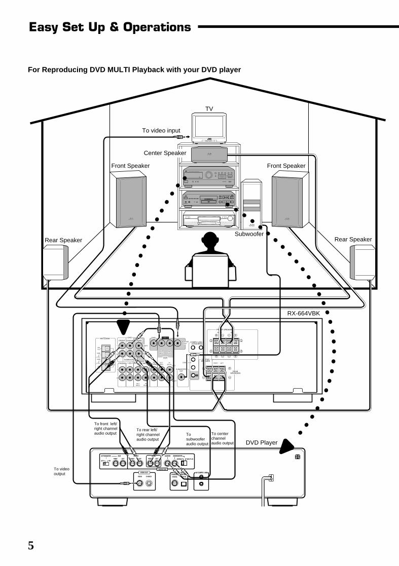
Easy Set Up & Operations
To videooutput
For Reproducing DVD MULTI Playback with your DVD player
AM LOOP
ANTENNA
COMPU LINK-3 (SYNCHRO)
FRONT SPEAKERS
FM
FM 75
AM EXT
OUT (REC)
IN (PLAY)
OUT (REC)
IN (PLAY)
GND
GND
DVD
OUT (REC)
MONITOR OUT
IN (PLAY)
RIGHT LEFT
RIGHT LEFT
+ +
– –
+
1
2
1
2
– – +
+ – – +
PHONO CD TAPE TV SOUND
L
R
SUBWOOFER OUT REAR
SPEAKERS
FRONT CENTER
SUBWOOFER
REAR
LEFT
RIGHT
VIDEO
VCRCENTER
SPEAKER
TV
AV COMPU LINK
L
R
DVD
AUDIO
LEFT
RIGHT
AV COMPU LINKDIGITAL OUTPCM/DOLBY DIGITAL
OPTICALCOAXIAL
AUDIO OUT
CENTER SUBWOOFER
NORMALRIGHT LEFT
REARFRONTRIGHT LEFTRIGHT LEFT
OFF ON
ATTENUATOR 2CH
VIDEO S-VIDEO
GAIN PLUS
VIDEO OUT
1
RX-664V AUDIO/VIDEO CONTROL RECEIVER
TV
To video input
Center Speaker
Front Speaker
SubwooferRear Speaker
RX-664VBK
DVD Player
Tosubwooferaudio output
To centerchannelaudio output
To front left/right channelaudio output
Rear Speaker
Front Speaker
To rear left/right channelaudio output
RX-664VBK(J)_0119-001B_En.01-23 98.1.6, 11:26 AM5
6
2. Select the source.00+
RM-SR664U
REMOTE CONTROL
7/P
+10
0
CENTER
REAR
( L )
TV
VOLUME
CH
VOLUMEMUTING
PHONO
DVD MULTI
CD
VCR
TAPE
TV
SOUND
TUNER/
BAND
DVDONE TOUCH
OPERATION
TV/VIDEO
SLEEP
REAR.
DVD MULTI
3. Adjust the volume.
RM-SR664U
REMOTE CONTROL
CENTER
RE( L )
VOLUMEMUTING
PHONO
DVD MULTI
CD
VCR
TAPE
TV
SOUND
TUNER/
BAND
DVDONE TOUCH
OPERATION
TV/VIDEO
SLEEP
VOLUME
1. Turn on the power.
100+
CATV
CONTROL
SOUND
CONTROL
CD-DISC
AUDIO
CATV/SATTV
VCR
DAP MODE
EFFECT
SEA MODE
1
4
7/P
+10
3D-PHONIC
SEA PRESET
DELAY2
5
8
0
SURROUND
TEST
MENU
RETURN/ENTER
3
6
9
10
CENTER
REAR
( L )
TV
VOLUME
CH
CD
TAPE
DVDONE TOUCH
OPERATION
TV/VIDEO
SLEEP
REAR.R
POWERAUDIO
RX-664V AUDIO/VIDEO CONTROL RECEIVER
STANDBY
POWER
PHONES SPEAKERS
MASTER VOLUME
– +
TUNER/BAND PRESET SEA SOURCE SURROUND ADJUST
ONE TOUCH OPERATION
SETTING
MEMORY
1 2
_ON —OFF
DVD MULTI
100+
CATV
CONTROL
SOUND
CONTROL
CD-DISC
AUDIO
RM-SR664U
REMOTE CONTROL
CATV/SATTV
VCR
DAP MODE
EFFECT
SEA MODE
1
4
7/P
+10
3D-PHONIC
SEA PRESET
DELAY2
5
8
0
SURROUND
TEST
MENU
RETURN/ENTER
3
6
9
10
CENTER
REAR
( L )
TV
VOLUME
CH
VOLUMEMUTING
PHONO
DVD MULTI
CD
VCR
TAPE
TV
SOUND
TUNER/
BAND
DVDONE TOUCH
OPERATION
TV/VIDEO
SLEEP
REAR.R
POWER
5. Surround settings arepreset at the factory.However, if you need tomake furtheradjustment, see pages38 and 39.
4. Set the remote controlto sound operationmode.
100+
CATV
CONTROL
SOUND
CONTROL
CD-DISC
AUDIO
CATV/SATTV
VCR
DAP MODE
EFFECT
SEA MODE
1
4
7/P
+10
3D-PHONIC
SEA PRESET
DELAY2
5
8
0
SURROUND
TEST
MENU
RETURN/ENTER
3
6
9
10
CENTER
REAR
( L )
TV
VOLUME
CH
NGDVD MULTI
CD
VCR
TAPE
TUNER/
BAND
DVDONE TOUCH
OPERATION
TV/VIDEO
SLEEP
REAR.R
POWER
SOUND
CONTROL
100+
RM-SR664U
REMOTE CONTROL
EFFECT
SEA MODE
1
4
7/P
+10
SEA PRESET5
8
0
RETURN/ENTER9
10
CENTER
REAR
( L )
TV
VOLUME
CH
VOLUMEMUTING
PHONO
DVD MULTI
CD
VCR
TAPE
TV
SOUND
TUNER/
BAND
DVDONE TOUCH
OPERATION
TV/VIDEO
SLEEP
REAR.R
CENTER
RX-664VBK(J)_0119-001B_En.01-23 98.1.6, 11:26 AM6
7
Getting StartedThis section explains how to connect stereo components and speakers to the receiver, and how to connectthe power supply.
Before Installation
General• Be sure your hands are dry.• Turn the power off to all components.• Read the manuals supplied with the components you are going to connect.
Locations• Install the receiver in a location that is level and protected from moisture.• The temperature around the receiver must be between 23˚ and 95˚ F
(–5˚ and 35˚ C).• Make sure there is good ventilation around the receiver. Poor ventilation could cause
overheating and damage the receiver.
Handling the receiver• Do not insert any metal object into the receiver.• Do not disassemble the receiver or remove screws, covers, or cabinet.• Do not expose the receiver to rain or moisture.
Checking the Supplied Accessories
Check to be sure you have all of the following items, which are supplied with thereceiver.The number in the parentheses indicates quantity of the pieces supplied.
• Remote Control (1)
• Batteries (2)
• AM Loop Antenna (1)
• FM Antenna (1)
If anything is missing, contact your dealer immediately.
RX-664VBK(J)_0119-001B_En.01-23 98.1.6, 11:26 AM7
8
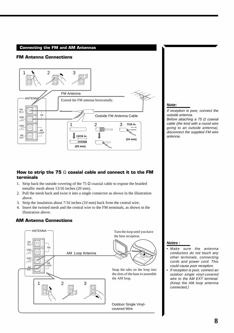
Connecting the FM and AM Antennas
FM Antenna Connections
Notes :• Make sure the antenna
conductors do not touch anyother terminals, connectingcords and power cord. Thiscould cause poor reception.
• If reception is poor, connect anoutdoor single vinyl-coveredwire to the AM EXT terminal.(Keep the AM loop antennaconnected.)
Note:If reception is poor, connect theoutside antenna.Before attaching a 75 Ω coaxialcable (the kind with a round wiregoing to an outside antenna),disconnect the supplied FM wireantenna.
7/16 in.
(10 mm)
Extend the FM antenna horizontally.
FM Antenna
Outside FM Antenna Cable
13/16 in.
(20 mm)
AM Antenna Connections
AM Loop Antenna
Turn the loop until you havethe best reception.
Snap the tabs on the loop intothe slots of the base to assemblethe AM loop.
Outdoor Single Vinyl-covered Wire
How to strip the 75 Ω coaxial cable and connect it to the FMterminals1. Strip back the outside covering of the 75 Ω coaxial cable to expose the braided
metallic mesh about 13/16 inches (20 mm).2. Pull the mesh back and twist it into a single connector as shown in the illustration
above.3. Strip the insulation about 7/16 inches (10 mm) back from the central wire.4. Insert the twisted mesh and the central wire to the FM terminals, as shown in the
illustration above.
AM EXT
AM LOOP
GND
FM 75
FMGND
ANTENNA
2 31
2 31
ANTENNA
2 31
AM EXT
GND
FM 75
GND
AM LOOP
FM
RX-664VBK(J)_0119-001B_En.01-23 98.1.6, 11:26 AM8
9
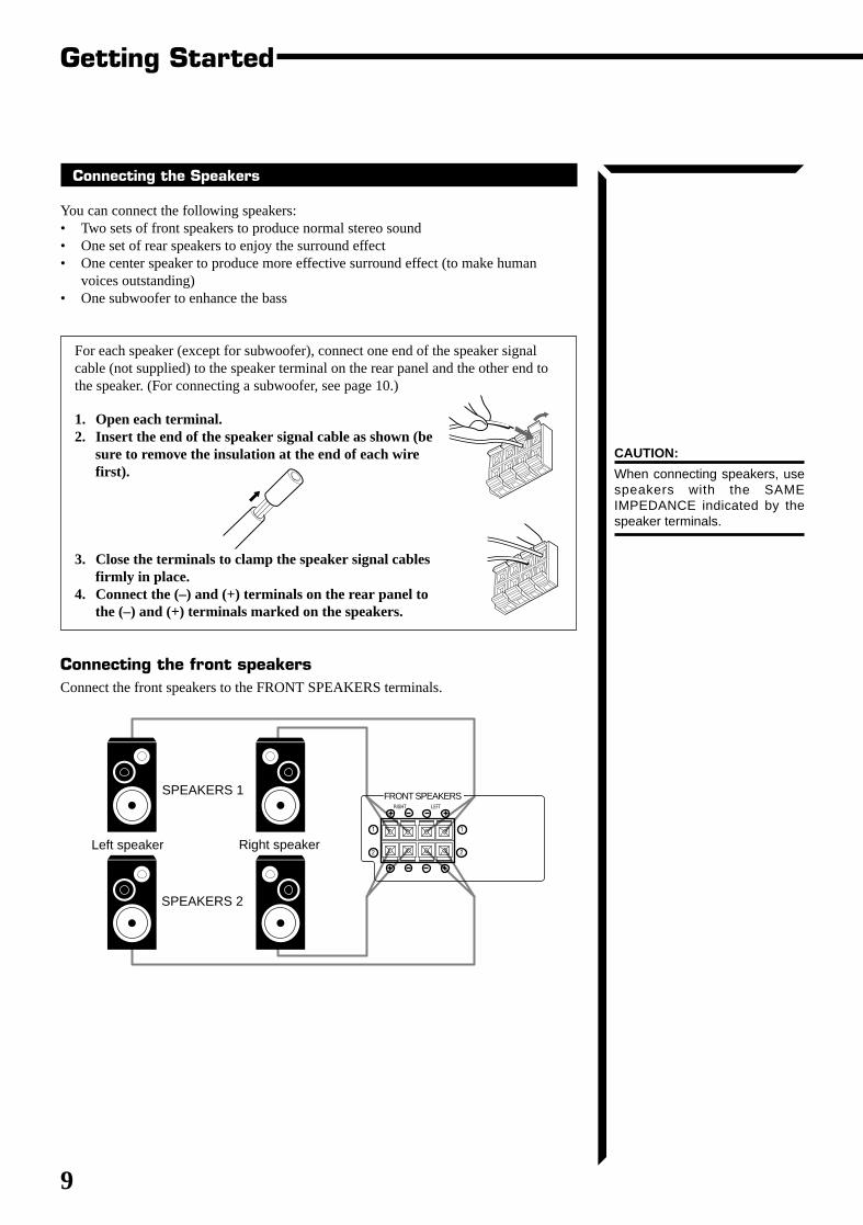
Connecting the Speakers
You can connect the following speakers:• Two sets of front speakers to produce normal stereo sound• One set of rear speakers to enjoy the surround effect• One center speaker to produce more effective surround effect (to make human
voices outstanding)• One subwoofer to enhance the bass
For each speaker (except for subwoofer), connect one end of the speaker signalcable (not supplied) to the speaker terminal on the rear panel and the other end tothe speaker. (For connecting a subwoofer, see page 10.)
1. Open each terminal.2. Insert the end of the speaker signal cable as shown (be
sure to remove the insulation at the end of each wirefirst).
3. Close the terminals to clamp the speaker signal cablesfirmly in place.
4. Connect the (–) and (+) terminals on the rear panel tothe (–) and (+) terminals marked on the speakers.
Connecting the front speakersConnect the front speakers to the FRONT SPEAKERS terminals.
CAUTION:
When connecting speakers, usespeakers with the SAMEIMPEDANCE indicated by thespeaker terminals.
Getting Started
Left speaker Right speaker
SPEAKERS 1
SPEAKERS 2
1
2
1
2
RIGHT LEFT
FRONT SPEAKERS
RX-664VBK(J)_0119-001B_En.01-23 98.1.6, 11:26 AM9
10
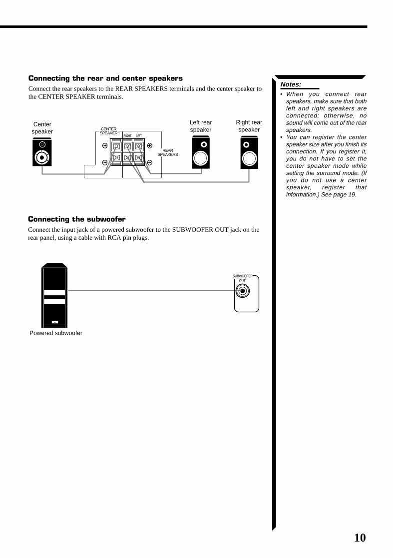
Connecting the rear and center speakersConnect the rear speakers to the REAR SPEAKERS terminals and the center speaker tothe CENTER SPEAKER terminals.
Notes:• When you connect rear
speakers, make sure that bothleft and right speakers areconnected; otherwise, nosound will come out of the rearspeakers.
• You can register the centerspeaker size after you finish itsconnection. If you register it,you do not have to set thecenter speaker mode whilesetting the surround mode. (Ifyou do not use a centerspeaker, register thatinformation.) See page 19.
Left rearspeaker
Centerspeaker
Right rearspeaker
RIGHT LEFT
REAR SPEAKERS
CENTER SPEAKER
Connecting the subwooferConnect the input jack of a powered subwoofer to the SUBWOOFER OUT jack on therear panel, using a cable with RCA pin plugs.
Powered subwoofer
SUBWOOFER OUT
RX-664VBK(J)_0119-001B_En.01-23 98.1.6, 11:26 AM10
11
Getting Started
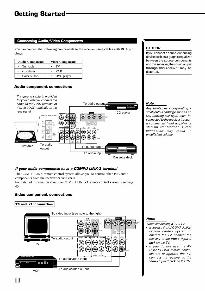
Note:When connecting a JVC TV:• If you use the AV COMPU LINK
remote control system tooperate the TV, connect thereceiver to the Video Input 2jack on the TV.
• If you do not use the AVCOMPU LINK remote controlsystem to operate the TV,connect the receiver to theVideo Input 1 jack on the TV.
CAUTION:
If you connect a sound-enhancingdevice such as a graphic equalizerbetween the source componentsand this receiver, the sound outputthrough this receiver may bedistorted.
Connecting Audio/Video Components
You can connect the following components to the receiver using cables with RCA pinplugs.
Audio Components Video Components
• Turntable • TV
• CD player • VCR
• Cassette deck • DVD player
TAPEPHONO CD
OUT (REC)
IN (PLAY)
VCR
OUT (REC)
IN (PLAY)
OUT (REC)
IN (PLAY)
MONITOR OUT
L
R
TV SOUND
DVD
LEFT
RIGHT
VIDEO
LEFT
RIGHT
DVDFRONT CENTER
SUBWOOFER
L
R
REAR
AUDIO
VHS
To video input (see note to the right)
To audio/video output
To audio output
To audio/video input
VCR
TV
Video component connections
TV and VCR connection
If your audio components have a COMPU LINK-3 terminalThe COMPU LINK remote control system allows you to control other JVC audiocomponents from the receiver or vice versa.For detailed information about the COMPU LINK-3 remote control system, see page40.
To audiooutput
Turntable
To audio output
CD player
Cassette deck
TAPEPHONO CD
OUT (REC)
IN (PLAY)
VCR
OUT (REC)
IN (PLAY)
OUT (REC)
IN (PLAY)
MONITOR OUT
L
R
TV SOUND
DVD
LEFT
RIGHT
VIDEO
LEFT
RIGHT
DVDFRONT CENTER
SUBWOOFER
L
R
REAR
AUDIO
ANTENNA
AM EXT
GND
FM 75
GND
AM LOOP
FM
To audio input
To audio output
If a ground cable is providedfor your turntable, connect thecable to the GND terminal ofthe AM LOOP terminals on therear panel.
Audio component connections
Note:Any turntables incorporating asmall-output cartridge such as anMC (moving-coil type) must beconnected to the receiver througha commercial head amplifier orstep-up transformer. Directconnection may result inunsufficient volume.
RX-664VBK(J)_0119-001B_En.01-23 98.1.6, 11:26 AM11
12
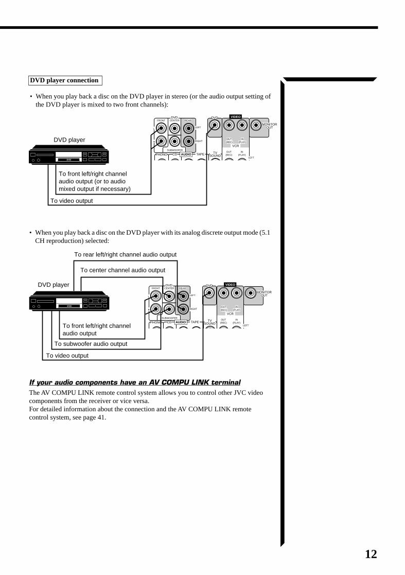
DVD player connection
• When you play back a disc on the DVD player in stereo (or the audio output setting ofthe DVD player is mixed to two front channels):
DVD player
To front left/right channelaudio output
To subwoofer audio output
To video output
To rear left/right channel audio output
To center channel audio output
DVD player
• When you play back a disc on the DVD player with its analog discrete output mode (5.1CH reproduction) selected:
If your audio components have an AV COMPU LINK terminalThe AV COMPU LINK remote control system allows you to control other JVC videocomponents from the receiver or vice versa.For detailed information about the connection and the AV COMPU LINK remotecontrol system, see page 41.
TAPEPHONO CD
OUT (REC)
IN (PLAY)
VCR
OUT (REC)
IN (PLAY)
OUT (REC)
IN (PLAY)
MONITOR OUT
L
R
TV SOUND
DVD
LEFT
RIGHT
VIDEO
LEFT
RIGHT
DVDFRONT CENTER
SUBWOOFER
L
R
REAR
AUDIO
DVD
To video output
To front left/right channelaudio output (or to audiomixed output if necessary)
TAPEPHONO CD
OUT (REC)
IN (PLAY)
VCR
OUT (REC)
IN (PLAY)
OUT (REC)
IN (PLAY)
MONITOR OUT
L
R
TV SOUND
DVD
LEFT
RIGHT
VIDEO
LEFT
RIGHT
DVDFRONT CENTER
SUBWOOFER
L
R
REAR
AUDIO
DVD
RX-664VBK(J)_0119-001B_En.01-23 98.1.6, 11:26 AM12
13
Notes:• A small amount of power is
always consumed even instandby mode. To switch off thepower completely, unplug thepower cord from the AC outlet.
• If the power cord is unplugged(or a power failure occurs),preset settings will be erased ina few days.
CAUTIONS:
• Do not touch the power cordwith wet hands.
• Do not pull on the power cordto unplug the receiver. Whenunplugging the receiver, alwaysgrasp the plug itself so as notto damage the cord.
+-
-+
R6P (SUM-3)/AA (15F)
Getting started
Connecting the Power Cord
Before plugging the receiver into an AC outlet, make sure that all connections havebeen made.When the power cord is connected, the STANDBY lamp above the POWER buttonlights up.
Keep the power cord away from the connecting cables for the TV, VCR, and antenna.The power cord may cause noise or screen interference. We recommend that you use acoaxial cable to connect the antenna, since it is well-shielded against interference.
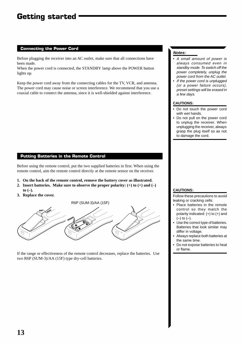
Putting Batteries in the Remote Control
Before using the remote control, put the two supplied batteries in first. When using theremote control, aim the remote control directly at the remote sensor on the receiver.
1. On the back of the remote control, remove the battery cover as illustrated.2. Insert batteries. Make sure to observe the proper polarity: (+) to (+) and (–)
to (–).3. Replace the cover.
If the range or effectiveness of the remote control decreases, replace the batteries. Usetwo R6P (SUM-3)/AA (15F) type dry-cell batteries.
CAUTIONS:
Follow these precautions to avoidleaking or cracking cells:• Place batteries in the remote
control so they match thepolarity indicated: (+) to (+) and(–) to (–).
• Use the correct type of batteries.Batteries that look similar maydiffer in voltage.
• Always replace both batteries atthe same time.
• Do not expose batteries to heator flame.
RX-664VBK(J)_0119-001B_En.01-23 98.1.6, 11:26 AM13
14
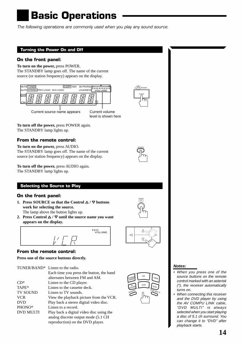
Basic OperationsThe following operations are commonly used when you play any sound source.
Turning the Power On and Off
On the front panel:To turn on the power, press POWER.The STANDBY lamp goes off. The name of the currentsource (or station frequency) appears on the display.
To turn off the power, press POWER again.The STANDBY lamp lights up.
From the remote control:To turn on the power, press AUDIO.The STANDBY lamp goes off. The name of the currentsource (or station frequency) appears on the display.
To turn off the power, press AUDIO again.The STANDBY lamp lights up.
Selecting the Source to Play
On the front panel:1. Press SOURCE so that the Control %%%%% / fififififi buttons
work for selecting the source.The lamp above the button lights up.
2. Press Control %%%%% / fififififi until the source name you wantappears on the display.
From the remote control:Press one of the source buttons directly.
TUNER/BAND* Listen to the radio.Each time you press the button, the bandalternates between FM and AM.
CD* Listen to the CD player.TAPE* Listen to the cassette deck.TV SOUND Listen to TV sounds.VCR View the playback picture from the VCR.DVD Play back a stereo digital video disc.PHONO* Listen to a record.DVD MULTI Play back a digital video disc using the
analog discrete output mode (5.1 CHreproduction) on the DVD player.
Current source name appears Current volumelevel is shown here
AUDIO
STANDBY
POWER
SOURCE
CD
VCR
DVD MULTI
TAPE
DVD
TUNER/
BAND
TV SOUND
PHONO
VOLUME
MUTE TUNED SLEEP SEA 3D-PHONIC
AUTO STEREO PRO LOGIC 3CH LOGIC HALL LOUDNESS
DAP
L
VOLUME
R
CH-MHzkHz
Notes:• When you press one of the
source buttons on the remotecontrol marked with an asterisk(*), the receiver automaticallyturns on.
• When connecting this receiverand the DVD player by usingthe AV COMPU LINK cable,“DVD MULTI” is alwaysselected when you start playinga disc of 5.1 ch surround. Youcan change it to “DVD” afterplayback starts.
RX-664VBK(J)_0119-001B_En.01-23 98.1.6, 11:27 AM14
15
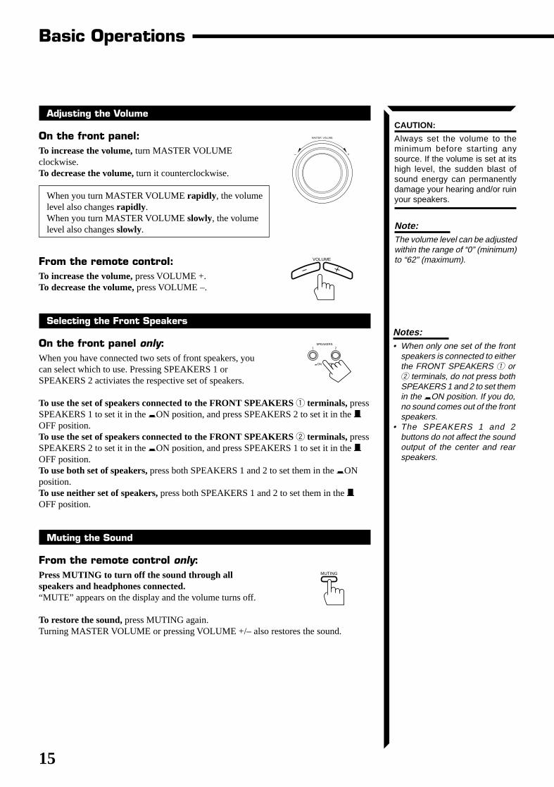
Adjusting the Volume
On the front panel:To increase the volume, turn MASTER VOLUMEclockwise.To decrease the volume, turn it counterclockwise.
When you turn MASTER VOLUME rapidly , the volumelevel also changes rapidly .When you turn MASTER VOLUME slowly, the volumelevel also changes slowly.
From the remote control:To increase the volume, press VOLUME +.To decrease the volume, press VOLUME –.
Selecting the Front Speakers
On the front panel only:When you have connected two sets of front speakers, youcan select which to use. Pressing SPEAKERS 1 orSPEAKERS 2 activiates the respective set of speakers.
To use the set of speakers connected to the FRONT SPEAKERS 1 terminals, pressSPEAKERS 1 to set it in the _ON position, and press SPEAKERS 2 to set it in the —OFF position.To use the set of speakers connected to the FRONT SPEAKERS 2 terminals, pressSPEAKERS 2 to set it in the _ON position, and press SPEAKERS 1 to set it in the —OFF position.To use both set of speakers, press both SPEAKERS 1 and 2 to set them in the _ONposition.To use neither set of speakers, press both SPEAKERS 1 and 2 to set them in the —OFF position.
Muting the Sound
From the remote control only:Press MUTING to turn off the sound through allspeakers and headphones connected.“MUTE” appears on the display and the volume turns off.
To restore the sound, press MUTING again.Turning MASTER VOLUME or pressing VOLUME +/– also restores the sound.
Notes:• When only one set of the front
speakers is connected to eitherthe FRONT SPEAKERS 1 or2 terminals, do not press bothSPEAKERS 1 and 2 to set themin the _ON position. If you do,no sound comes out of the frontspeakers.
• The SPEAKERS 1 and 2buttons do not affect the soundoutput of the center and rearspeakers.
VOLUME
MASTER VOLUME
– +
SPEAKERS1 2
_ON —OFF
MUTING
Basic Operations
Note:The volume level can be adjustedwithin the range of “0” (minimum)to “62” (maximum).
CAUTION:
Always set the volume to theminimum before starting anysource. If the volume is set at itshigh level, the sudden blast ofsound energy can permanentlydamage your hearing and/or ruinyour speakers.
RX-664VBK(J)_0119-001B_En.01-23 98.1.6, 11:27 AM15
16
Recording a Source
You can record any source playing through the receiver to a cassette deck connected tothe TAPE jacks and the VCR connected to the VCR jacks at the same time.While recording, you can listen to the selected sound source at whatever sound levelyou like, without affecting the sound levels of the recording.
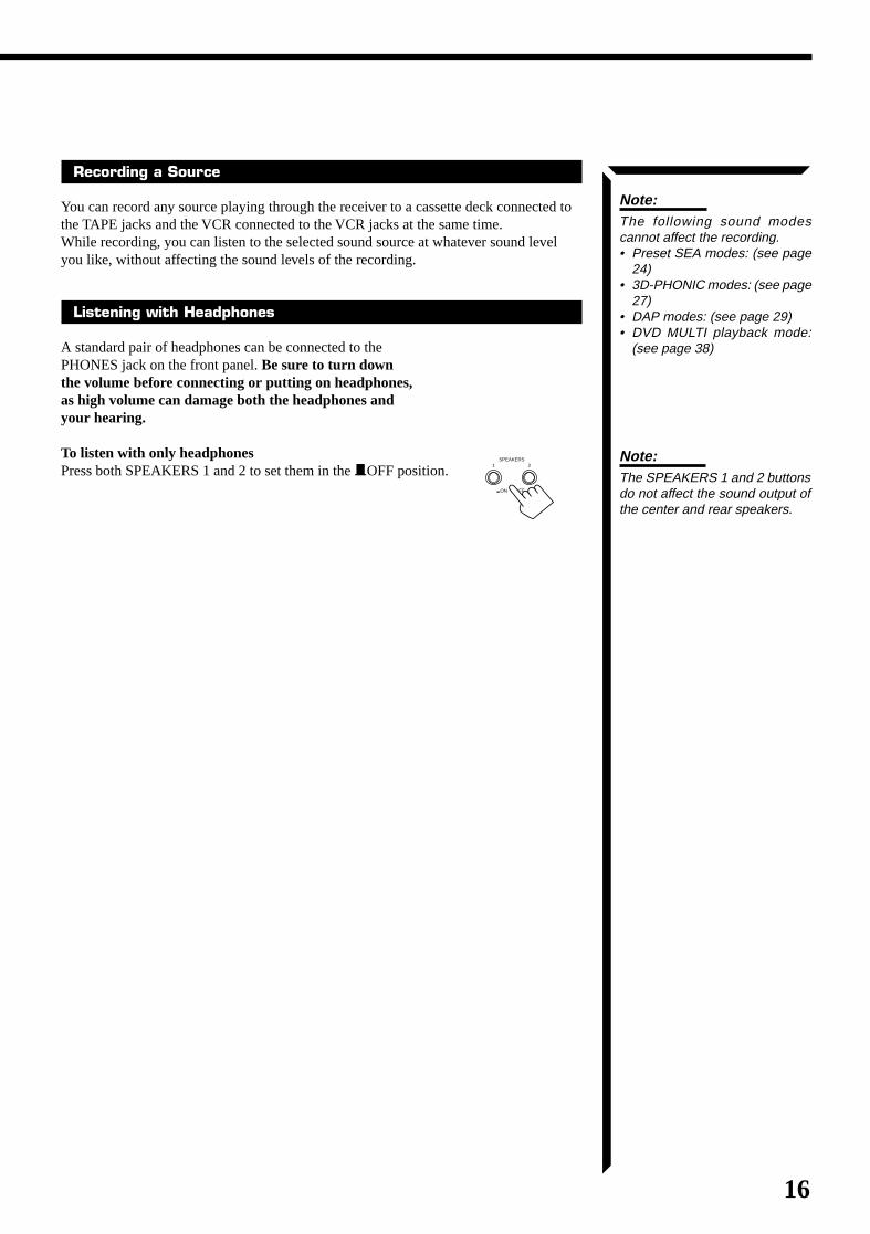
Listening with Headphones
A standard pair of headphones can be connected to thePHONES jack on the front panel. Be sure to turn downthe volume before connecting or putting on headphones,as high volume can damage both the headphones andyour hearing.
To listen with only headphonesPress both SPEAKERS 1 and 2 to set them in the —OFF position.
Note:The following sound modescannot affect the recording.• Preset SEA modes: (see page
24)• 3D-PHONIC modes: (see page
27)• DAP modes: (see page 29)• DVD MULTI playback mode:
(see page 38)
SPEAKERS1 2
_ON —OFF
Note:The SPEAKERS 1 and 2 buttonsdo not affect the sound output ofthe center and rear speakers.
RX-664VBK(J)_0119-001B_En.01-23 98.1.6, 11:27 AM16
17
Adjusting the Front Speaker Output Balance
If the sounds you hear from the front right and left speakers are unequal, you can adjustthe speaker output balance.
On the front panel only:1. Press SETTING so that the Control %%%%% / fififififi / @@@@@ / #####
buttons work for adjusting the balance.The lamp above the button lights up.
2. Press Control %%%%% / fififififi until “BALANCE” appears onthe display.
3. Press Control @@@@@ / ##### to adjust the balance.• Pressing Control @ decreases the right channel
output.• Pressing Control # decreases the left channel output.
Listening at Low Volume (Loudness)
Human ears are not sensitive to bass at low volume. To compensate for this, theLoudness function automatically boosts the bass level as you lower the volume.
On the front panel only:1. Press SETTING so that the Control %%%%% / fififififi / @@@@@ / ##### buttons work for setting the
Loudness function.The lamp above the button lights up.
2. Press Control %%%%% / fififififi until “LOUDNESS” appears on the display.3. Press Control @@@@@ / ##### to set the Loudness function to “ON” or “OFF.”
• Select “ON ” to activate the Loudness function.The LOUDNESS indicator lights up on the display.
• Select “OFF” to cancel it.The indicator goes off.
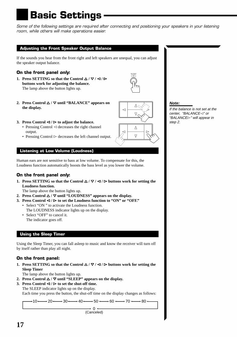
Using the Sleep Timer
Using the Sleep Timer, you can fall asleep to music and know the receiver will turn offby itself rather than play all night.
On the front panel:1. Press SETTING so that the Control %%%%% / fififififi / @@@@@ / ##### buttons work for setting the
Sleep TimerThe lamp above the button lights up.
2. Press Control %%%%% / fififififi until “SLEEP” appears on the display.3. Press Control @@@@@ / ##### to set the shut-off time.
The SLEEP indicator lights up on the display.Each time you press the button, the shut-off time on the display changes as follows:
Basic SettingsSome of the following settings are required after connecting and positioning your speakers in your listeningroom, while others will make operations easier.
SETTING
2010 30 40 50 60 70 80
0(Canceled)
Note:If the balance is not set at thecenter, “BALANCE@” or“BALANCE#” will appear instep 2.
RX-664VBK(J)_0119-001B_En.01-23 98.1.6, 11:27 AM17
18
When the shut-off time comesThe receiver turns off automatically.
To check or change the time remaining until the shut-off time1. Press SETTING, if necessary, so that the Control % / fi / @ / # buttons work for
setting the Sleep Timer.2. Press Control % / fi, if necessary, until “SLEEP” appears on the display.3. Press Control @ / #.
The remaining time until the shut-off time appears in minutes.• To change the shut-off time, press Control @ / # repeatedly.
To cancel the Sleep TimerPress Control @ / # repeatedly in step 3 above until “0” appears on the display. (TheSLEEP indicator goes off.)Turning off the power also cancels the Sleep Timer.
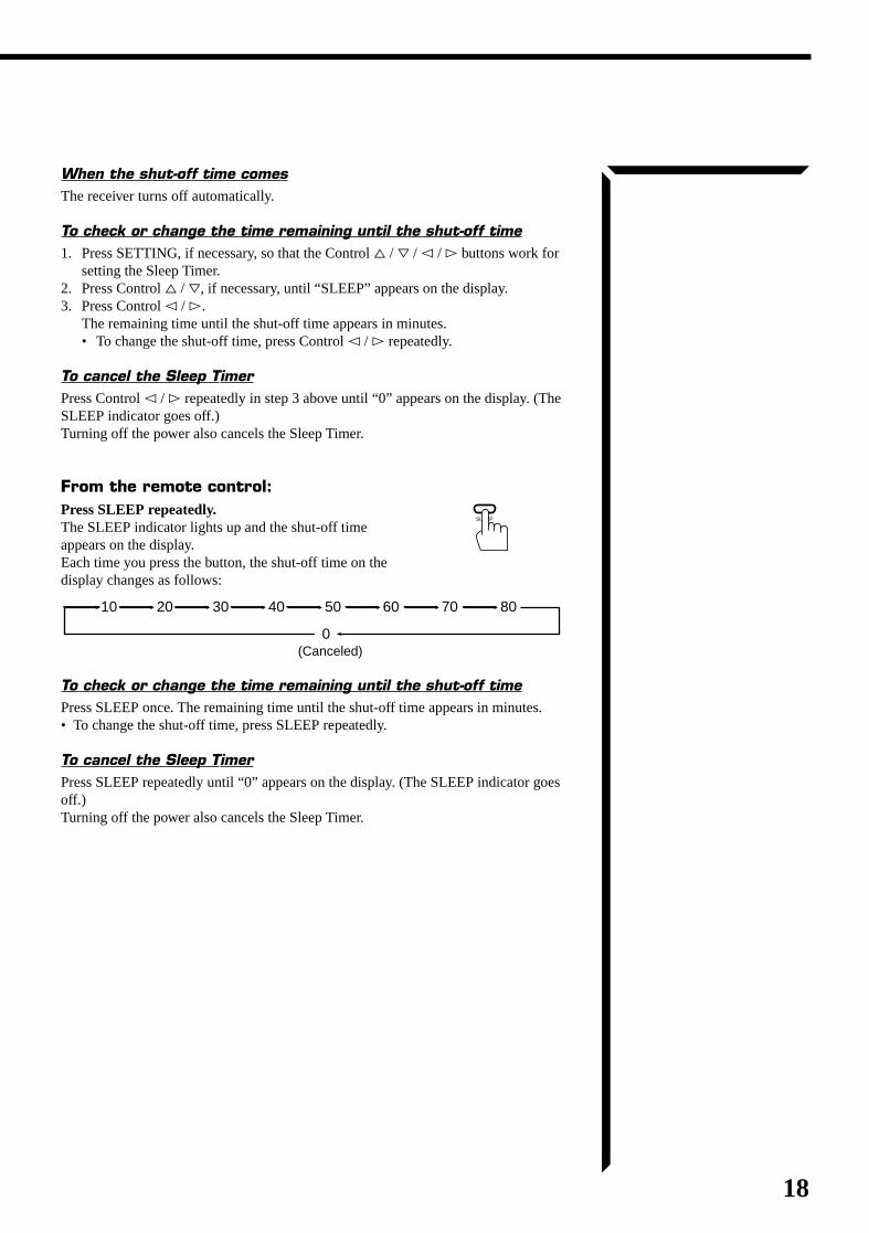
From the remote control:Press SLEEP repeatedly.The SLEEP indicator lights up and the shut-off timeappears on the display.Each time you press the button, the shut-off time on thedisplay changes as follows:
To check or change the time remaining until the shut-off timePress SLEEP once. The remaining time until the shut-off time appears in minutes.• To change the shut-off time, press SLEEP repeatedly.
To cancel the Sleep TimerPress SLEEP repeatedly until “0” appears on the display. (The SLEEP indicator goesoff.)Turning off the power also cancels the Sleep Timer.
(Canceled)
2010 30 40 50 60 70 80
0
SLEEP
RX-664VBK(J)_0119-001B_En.01-23 98.1.6, 11:27 AM18
19
Selecting the Center Speaker Size
You can register the information about the center speaker after all connections arecompleted.If you do this registration first, you do not have to adjust the center speaker mode whenyou want to activate the surround sound.
On the front panel only:1. Press SETTING so that the Control %%%%% / fififififi / @@@@@ / ##### buttons work for selecting
the center speaker size.The lamp above the button lights up.
2. Press Control %%%%% / fififififi until “CNTR SPK” (Center Speaker) appears on thedisplay.
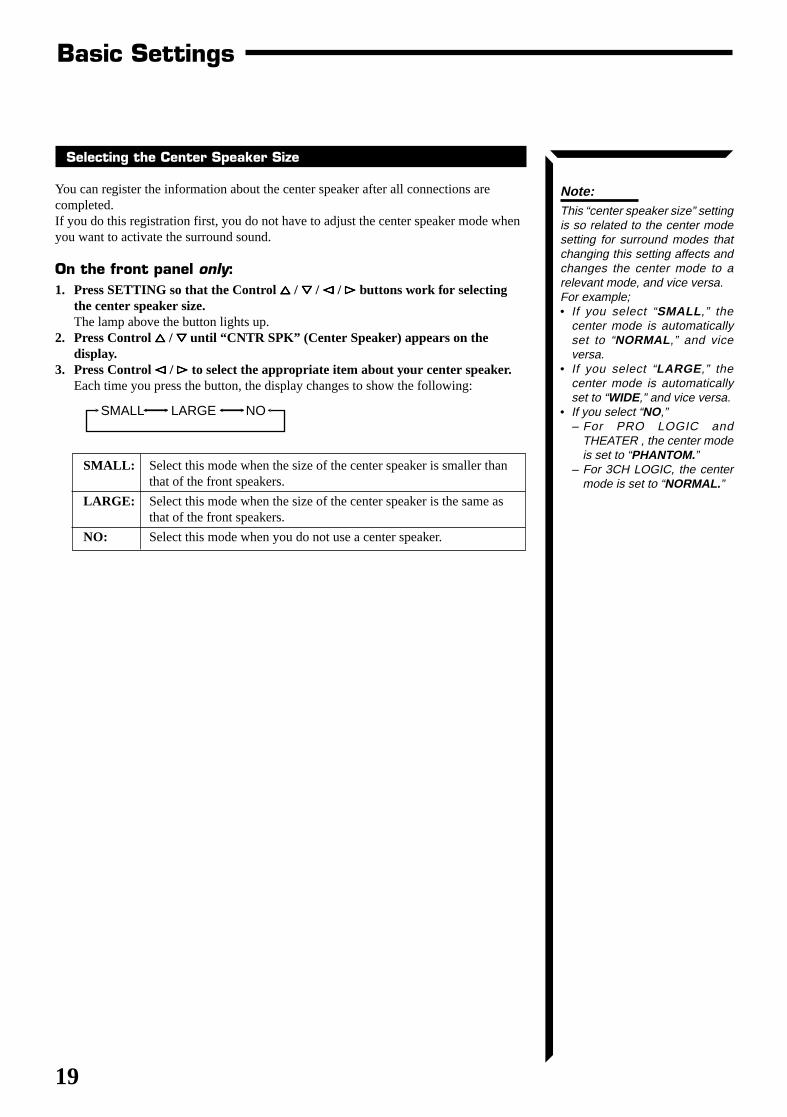
3. Press Control @@@@@ / ##### to select the appropriate item about your center speaker.Each time you press the button, the display changes to show the following:
SMALL: Select this mode when the size of the center speaker is smaller thanthat of the front speakers.
LARGE: Select this mode when the size of the center speaker is the same asthat of the front speakers.
NO: Select this mode when you do not use a center speaker.
Note:This “center speaker size” settingis so related to the center modesetting for surround modes thatchanging this setting affects andchanges the center mode to arelevant mode, and vice versa.For example;• If you select “SMALL ,” the
center mode is automaticallyset to “NORMAL ,” and viceversa.
• If you select “LARGE ,” thecenter mode is automaticallyset to “WIDE,” and vice versa.
• If you select “NO,”– For PRO LOGIC and
THEATER , the center modeis set to “PHANTOM.”
– For 3CH LOGIC, the centermode is set to “NORMAL. ”
SMALL LARGE NO
Basic Settings
RX-664VBK(J)_0119-001B_En.01-23 98.1.6, 11:27 AM19
20
One Touch OperationThis receiver can memorize the optimum sound settings for each playing source.
About the One Touch Operation
JVC’s One Touch Operation function is used to assign and store different sound settingsfor each different playing source. By using this function, you do not have to change thesettings every time you change the source. The stored settings for the newly selectedsource are automatically recalled.
The following can be stored for each source:• Volume level (see page 15)• Balance (see page 17)• Loudness (see page 17)• Preset SEA modes (see page 24)• 3D-PHONIC mode settings (see page 27)• DAP mode settings (see page 29)• Surround mode settings (see page 37)
Using the One Touch Operation
To store the sound settings1. Press ONE TOUCH OPERATION.
The ONE TOUCH OPERATION lamp lights up, thenthe previously memorized settings are recalled andappear on the display in turn.
2. Adjust the sound using the functions listed above.The newly adjusted settings are memorized.
To recall the sound settingsWith the ONE TOUCH OPERATION lamp lit, the settingsfor the currently selected source is recalled, and appears onthe display when the source is selected.
To cancel the One Touch Operation functionPress ONE TOUCH OPERATION so that the lamp goesoff.(Even though the One Touch Operation function is canceled, the recalled sound effectsremain active.)
ONE TOUCH OPERATION
ONE TOUCH OPERATION
Notes:• If the source is TUNER/BAND,
the One Touch Operationfunction memorizes the settingseach for the FM and AM band.
• 3D-PHONIC mode, DAP mode,and surround mode cannot beused at the same time.
RX-664VBK(J)_0119-001B_En.01-23 98.1.6, 11:27 AM20
21
Notes:• When you hold down Control @
/ # in step 3, the frequencykeeps changing until you pressControl @ / # again or a stationis tuned in.
• When a station of sufficientsignal strength is tuned in, theTUNED indicator lights up onthe display.When an FM stereo program isreceived, the STEREO indicatoralso lights up.
Receiving Radio BroadcastsYou can browse through all the stations or use the preset function to go immediately to a particularstation.
Tuning in Stations Manually
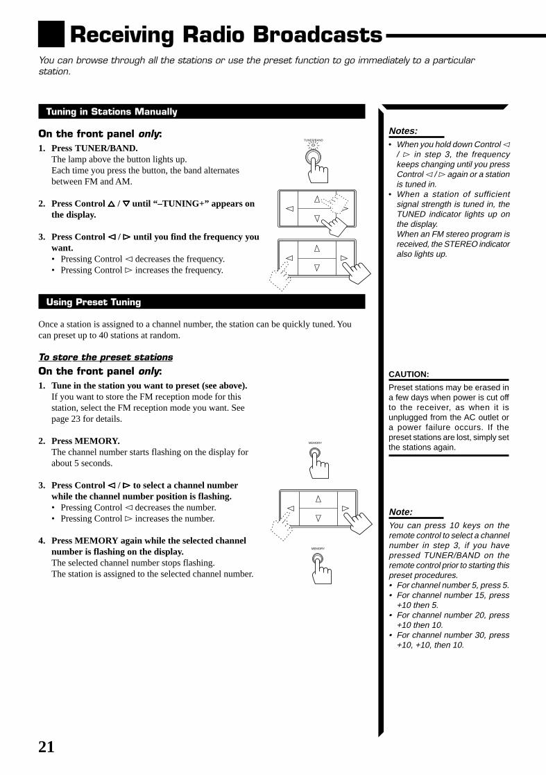
On the front panel only:1. Press TUNER/BAND.
The lamp above the button lights up.Each time you press the button, the band alternatesbetween FM and AM.
2. Press Control %%%%% / fififififi until “–TUNING+” appears onthe display.
3. Press Control @@@@@ / ##### until you find the frequency youwant.• Pressing Control @ decreases the frequency.• Pressing Control # increases the frequency.
Using Preset Tuning
Once a station is assigned to a channel number, the station can be quickly tuned. Youcan preset up to 40 stations at random.
To store the preset stationsOn the front panel only:1. Tune in the station you want to preset (see above).
If you want to store the FM reception mode for thisstation, select the FM reception mode you want. Seepage 23 for details.
2. Press MEMORY.The channel number starts flashing on the display forabout 5 seconds.
3. Press Control @@@@@ / ##### to select a channel numberwhile the channel number position is flashing.• Pressing Control @ decreases the number.• Pressing Control # increases the number.
4. Press MEMORY again while the selected channelnumber is flashing on the display.The selected channel number stops flashing.The station is assigned to the selected channel number.
CAUTION:
Preset stations may be erased ina few days when power is cut offto the receiver, as when it isunplugged from the AC outlet ora power failure occurs. If thepreset stations are lost, simply setthe stations again.
Note:You can press 10 keys on theremote control to select a channelnumber in step 3, if you havepressed TUNER/BAND on theremote control prior to starting thispreset procedures.• For channel number 5, press 5.• For channel number 15, press
+10 then 5.• For channel number 20, press
+10 then 10.• For channel number 30, press
+10, +10, then 10.
MEMORY
MEMORY
TUNER/BAND
RX-664VBK(J)_0119-001B_En.01-23 98.1.6, 11:27 AM21
22
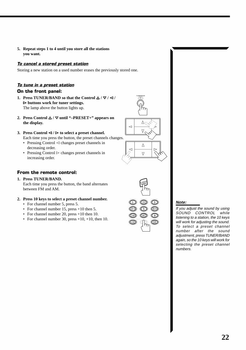
5. Repeat steps 1 to 4 until you store all the stationsyou want.
To cancel a stored preset stationStoring a new station on a used number erases the previously stored one.
To tune in a preset stationOn the front panel:1. Press TUNER/BAND so that the Control %%%%% / fififififi / @@@@@ /
##### buttons work for tuner settings.The lamp above the button lights up.
2. Press Control %%%%% / fififififi until “–PRESET+” appears onthe display.
3. Press Control @@@@@ / ##### to select a preset channel.Each time you press the button, the preset channels changes.• Pressing Control @ changes preset channels in
decreasing order.• Pressing Control # changes preset channels in
increasing order.
From the remote control:1. Press TUNER/BAND.
Each time you press the button, the band alternatesbetween FM and AM.
2. Press 10 keys to select a preset channel number.• For channel number 5, press 5.• For channel number 15, press +10 then 5.• For channel number 20, press +10 then 10.• For channel number 30, press +10, +10, then 10.
TUNER/BAND
TUNER/
BAND
100+ RETURN/ENTER
321
654
987/P
+10 10
DAP MODE 3D-PHONIC SURROUND
– REAR•R +
EFFECT DELAY TEST
SEA MODE SEA PRESET MENU
Note:If you adjust the sound by usingSOUND CONTROL whilelistening to a station, the 10 keyswill work for adjusting the sound.To select a preset channelnumber after the soundadjustment, press TUNER/BANDagain, so the 10 keys will work forselecting the preset channelnumbers.
RX-664VBK(J)_0119-001B_En.01-23 98.1.6, 11:27 AM22
23
Receiving Radio Broadcasts
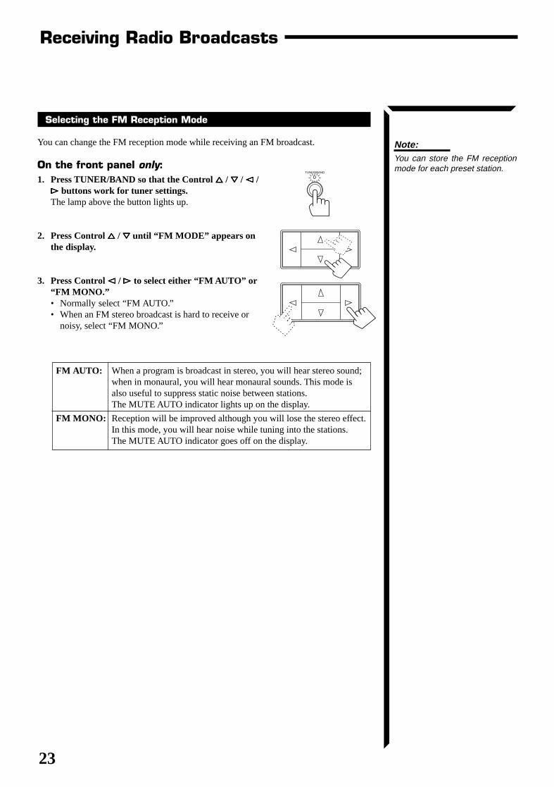
Note:You can store the FM receptionmode for each preset station.
Selecting the FM Reception Mode
You can change the FM reception mode while receiving an FM broadcast.
On the front panel only:1. Press TUNER/BAND so that the Control %%%%% / fififififi / @@@@@ /
##### buttons work for tuner settings.The lamp above the button lights up.
2. Press Control %%%%% / fififififi until “FM MODE” appears onthe display.
3. Press Control @@@@@ / ##### to select either “FM AUTO” or“FM MONO.”• Normally select “FM AUTO.”• When an FM stereo broadcast is hard to receive or
noisy, select “FM MONO.”
FM AUTO: When a program is broadcast in stereo, you will hear stereo sound;when in monaural, you will hear monaural sounds. This mode isalso useful to suppress static noise between stations.The MUTE AUTO indicator lights up on the display.
FM MONO: Reception will be improved although you will lose the stereo effect.In this mode, you will hear noise while tuning into the stations.The MUTE AUTO indicator goes off on the display.
TUNER/BAND
RX-664VBK(J)_0119-001B_En.01-23 98.1.6, 11:27 AM23
24
Using the Preset SEA ModesThe preset SEA (Sound Effect Amplifier) modes give you control of the way your music sounds.
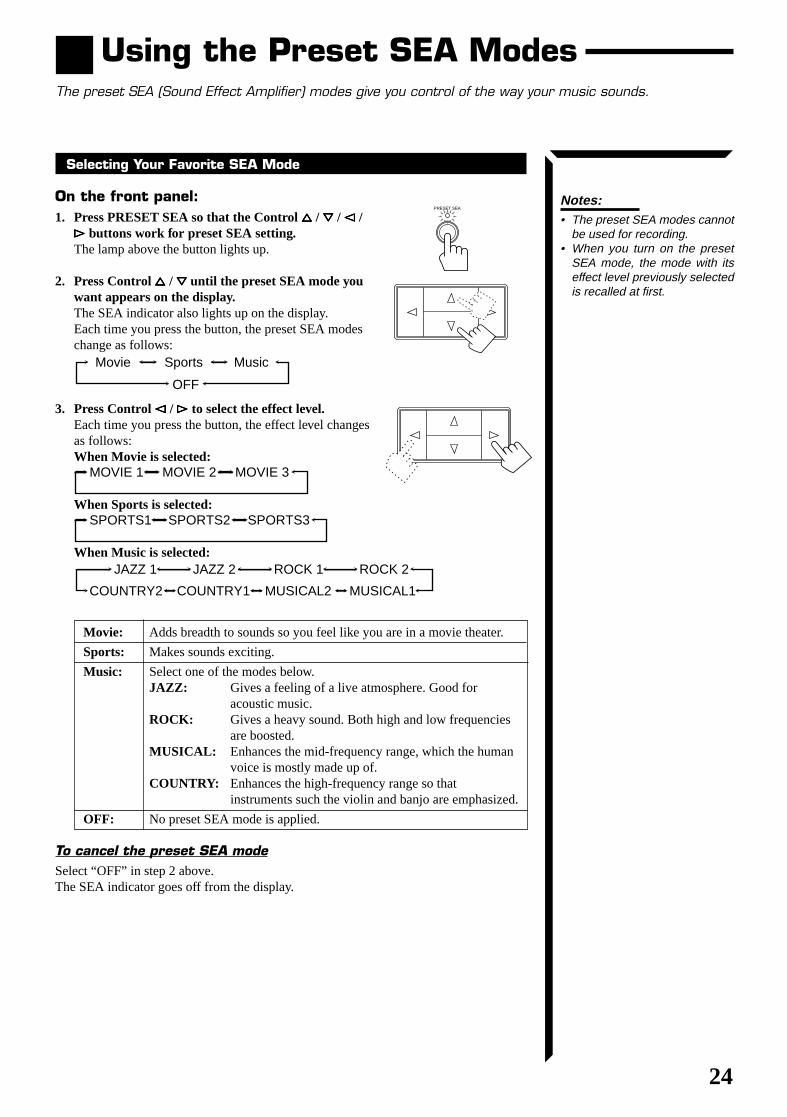
Notes:• The preset SEA modes cannot
be used for recording.• When you turn on the preset
SEA mode, the mode with itseffect level previously selectedis recalled at first.
Selecting Your Favorite SEA Mode
On the front panel:1. Press PRESET SEA so that the Control %%%%% / fififififi / @@@@@ /
##### buttons work for preset SEA setting.The lamp above the button lights up.
2. Press Control %%%%% / fififififi until the preset SEA mode youwant appears on the display.The SEA indicator also lights up on the display.Each time you press the button, the preset SEA modeschange as follows:
3. Press Control @@@@@ / ##### to select the effect level.Each time you press the button, the effect level changesas follows:When Movie is selected:
When Sports is selected:
When Music is selected:
Movie: Adds breadth to sounds so you feel like you are in a movie theater.
Sports: Makes sounds exciting.
Music: Select one of the modes below.JAZZ: Gives a feeling of a live atmosphere. Good for
acoustic music.ROCK: Gives a heavy sound. Both high and low frequencies
are boosted.MUSICAL: Enhances the mid-frequency range, which the human
voice is mostly made up of.COUNTRY: Enhances the high-frequency range so that
instruments such the violin and banjo are emphasized.
OFF: No preset SEA mode is applied.
To cancel the preset SEA modeSelect “OFF” in step 2 above.The SEA indicator goes off from the display.
PRESET SEA
MOVIE 1 MOVIE 2 MOVIE 3
SPORTS1 SPORTS2 SPORTS3
JAZZ 1 JAZZ 2
COUNTRY2 COUNTRY1 MUSICAL2 MUSICAL1
ROCK 1 ROCK 2
Movie Sports Music
OFF
RX-664VBK(J)_0119-001B_En.24-50 98.1.6, 11:28 AM24
25
Using the Preset SEA Modes
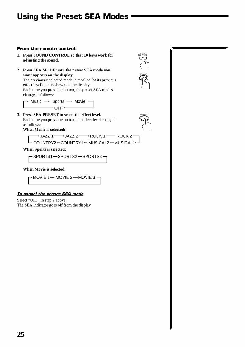
From the remote control:1. Press SOUND CONTROL so that 10 keys work for
adjusting the sound.
2. Press SEA MODE until the preset SEA mode youwant appears on the display.The previously selected mode is recalled (at its previouseffect level) and is shown on the display.Each time you press the button, the preset SEA modeschange as follows:
3. Press SEA PRESET to select the effect level.Each time you press the button, the effect level changesas follows:When Music is selected:
When Sports is selected:
When Movie is selected:
To cancel the preset SEA modeSelect “OFF” in step 2 above.The SEA indicator goes off from the display.
SOUND CONTROL
7/PSEA MODE
8SEA PRESET
JAZZ 1 JAZZ 2
COUNTRY2 COUNTRY1 MUSICAL2 MUSICAL1
ROCK 1 ROCK 2
MOVIE 1 MOVIE 2 MOVIE 3
SPORTS1 SPORTS2 SPORTS3
MovieSportsMusic
OFF
RX-664VBK(J)_0119-001B_En.24-50 98.1.6, 11:28 AM25
26
Using the Surround ProcessorThe built-in surround processor provides three groups of Surround Processor modes — JVC 3D-PHONICmode, DAP (Digital Acoustic Processor) mode, and surround modes (Dolby Surround and JVC TheaterSurround).
Direct sounds
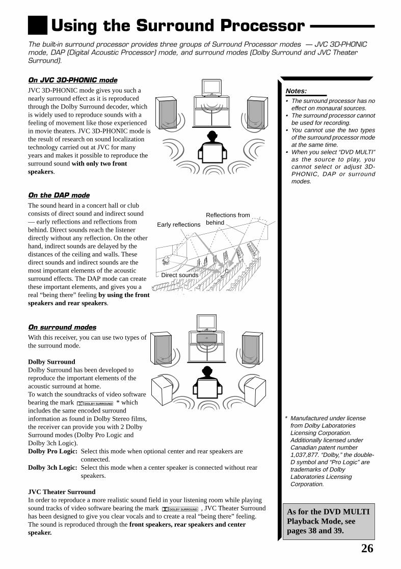
On JVC 3D-PHONIC modeJVC 3D-PHONIC mode gives you such anearly surround effect as it is reproducedthrough the Dolby Surround decoder, whichis widely used to reproduce sounds with afeeling of movement like those experiencedin movie theaters. JVC 3D-PHONIC mode isthe result of research on sound localizationtechnology carried out at JVC for manyyears and makes it possible to reproduce thesurround sound with only two frontspeakers.
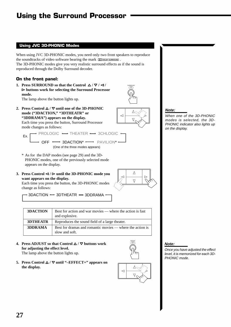
On the DAP modeThe sound heard in a concert hall or clubconsists of direct sound and indirect sound— early reflections and reflections frombehind. Direct sounds reach the listenerdirectly without any reflection. On the otherhand, indirect sounds are delayed by thedistances of the ceiling and walls. Thesedirect sounds and indirect sounds are themost important elements of the acousticsurround effects. The DAP mode can createthese important elements, and gives you areal “being there” feeling by using the frontspeakers and rear speakers.
On surround modesWith this receiver, you can use two types ofthe surround mode.
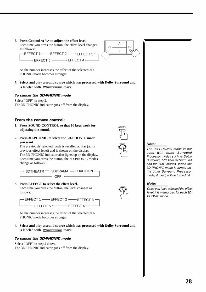
Dolby SurroundDolby Surround has been developed toreproduce the important elements of theacoustic surround at home.To watch the soundtracks of video softwarebearing the mark DOLBY SURROUND * whichincludes the same encoded surroundinformation as found in Dolby Stereo films,the receiver can provide you with 2 DolbySurround modes (Dolby Pro Logic andDolby 3ch Logic).Dolby Pro Logic: Select this mode when optional center and rear speakers are
connected.Dolby 3ch Logic: Select this mode when a center speaker is connected without rear
speakers.
JVC Theater SurroundIn order to reproduce a more realistic sound field in your listening room while playingsound tracks of video software bearing the mark DOLBY SURROUND , JVC Theater Surroundhas been designed to give you clear vocals and to create a real “being there” feeling.The sound is reproduced through the front speakers, rear speakers and centerspeaker.
Reflections frombehindEarly reflections
Notes:• The surround processor has no
effect on monaural sources.• The surround processor cannot
be used for recording.• You cannot use the two types
of the surround processor modeat the same time.
• When you select “DVD MULTI”as the source to play, youcannot select or adjust 3D-PHONIC, DAP or surroundmodes.
* Manufactured under licensefrom Dolby LaboratoriesLicensing Corporation.Additionally licensed underCanadian patent number1,037,877. “Dolby,” the double-D symbol and “Pro Logic” aretrademarks of DolbyLaboratories LicensingCorporation.
As for the DVD MULTIPlayback Mode, seepages 38 and 39.
RX-664VBK(J)_0119-001B_En.24-50 98.1.6, 11:29 AM26
27
Using the Surround Processor
SURROUND
Using JVC 3D-PHONIC Modes
When using JVC 3D-PHONIC modes, you need only two front speakers to reproducethe soundtracks of video software bearing the mark DOLBY SURROUND .The 3D-PHONIC modes give you very realistic surround effects as if the sound isreproduced through the Dolby Surround decoder.
On the front panel:1. Press SURROUND so that the Control %%%%% / fififififi / @@@@@ /
##### buttons work for selecting the Surround Processormode.The lamp above the button lights up.
2. Press Control %%%%% / fififififi until one of the 3D-PHONICmode (“3DACTION,” “3DTHEATR” or“3DDRAMA”) appears on the display.Each time you press the button, Surround Processormode changes as follows:
* As for the DAP modes (see page 29) and the 3D-PHONIC modes, one of the previously selected modeappears on the display.
3. Press Control @@@@@ / ##### until the 3D-PHONIC mode youwant appears on the display.Each time you press the button, the 3D-PHONIC modeschange as follows:
3DACTION Best for action and war movies — where the action is fastand explosive.
3DTHEATR Reproduces the sound field of a large theater.
3DDRAMA Best for dramas and romantic movies — where the action isslow and soft.
4. Press ADJUST so that Control %%%%% / fififififi buttons workfor adjusting the effect level.The lamp above the button lights up.
5. Press Control %%%%% / fififififi until “–EFFECT+” appears onthe display.
3DACTION 3DDRAMA3DTHEATR
Note:Once you have adjusted the effectlevel, it is memorized for each 3D-PHONIC mode.
ADJUST
Ex.
Note:When one of the 3D-PHONICmodes is selected, the 3D-PHONIC indicator also lights upon the display.
PROLOGIC THEATER
PAVILION*
3CHLOGIC
3DACTION*OFF(One of the three modes appears)
RX-664VBK(J)_0119-001B_En.24-50 98.1.6, 11:29 AM27
28
6. Press Control @@@@@ / ##### to adjust the effect level.Each time you press the button, the effect level changesas follows:
As the number increases the effect of the selected 3D-PHONIC mode becomes stronger.
7. Select and play a sound source which was processed with Dolby Surround andis labeled with DOLBY SURROUND mark.
To cancel the 3D-PHONIC modeSelect “OFF” in step 2.The 3D-PHONIC indicator goes off from the display.
From the remote control:1. Press SOUND CONTROL so that 10 keys work for
adjusting the sound.
2. Press 3D-PHONIC to select the 3D-PHONIC modeyou want.The previously selected mode is recalled at first (at itsprevious effect level) and is shown on the display.The 3D-PHONIC indicator also lights up on the display.Each time you press the button, the 3D-PHONIC modeschange as follows:
3. Press EFFECT to select the effect level.Each time you press the button, the level changes asfollows:
As the number increases,the effect of the selected 3D-PHONIC mode becomes stronger.
4. Select and play a sound source which was processed with Dolby Surround andis labeled with DOLBY SURROUND mark.
To cancel the 3D-PHONIC modeSelect “OFF” in step 2 above.The 3D-PHONIC indicator goes off from the display.
EFFECT 1 EFFECT 2
EFFECT 4
EFFECT 3
EFFECT 5
Note:The 3D-PHONIC mode is notused with other SurroundProcessor modes such as DolbySurround, JVC Theater Surroundand the DAP modes. When the3D-PHONIC mode is turned on,the other Surround Processormode, if used, will be turned off.
23D-PHONIC
SOUND CONTROL
EFFECT 1 EFFECT 2
EFFECT 4
EFFECT 3
EFFECT 5
4EFFECT
3DACTION3DDRAMA3DTHEATR
OFF
Note:Once you have adjusted the effectlevel, it is memorized for each 3D-PHONIC mode.
RX-664VBK(J)_0119-001B_En.24-50 98.1.6, 11:29 AM28
29
Using the Surround Processor
Ex. PROLOGIC THEATER
PAVILION*
3CHLOGIC
3DACTION*OFF(One of the five modes appears)
DANCE C LIVE C
PAVILION
HALL
HEAD P
ADJUST
Using the DAP Modes
You can use five DAP modes — “Dance Club, Live Club, Hall, Pavilion, andHeadphones.” These modes (except “Headphones”) require the front speakers and therear speakers, but do not require a center speaker to enlarge the sound field.
Among the DAP modes, “Headphones” is very special. It can create the same stereosound as you listen through the speakers off air while listening to a source usingheadphones. So, you can feel as if you were not using the headphones and listening tomusic in a room.
On the front panel:1. Press SURROUND so that the Control %%%%% / fififififi / @@@@@ / #####
buttons work for selecting the Surround Processormode.The lamp above the button lights up.
2. Press Control %%%%% / fififififi until one of the DAP mode(“HEAD P,” “PAVILION,” “HALL,” “LIVE C” or“DANCE C”) appears on the display.Each time you press the button, the Surround Processormodes change as follows:
* As for the 3D-PHONIC modes (see page 27) and theDAP modes, one of the previously selected modeappears on the display.
3. Press Control @@@@@ / ##### until the DAP mode you wantappears on the display.Each time you press the button, the DAP modes changeas follows:
HEAD Phones* Gives a spacious stereo effect when listening with headphones.
PAVILION Gives the spacious feeling of a pavilion with a high ceiling.
HALL Gives clear vocal and the feeling of a concert hall.
LIVE Club Gives the feeling of a live music club with a low ceiling.
DANCE Club Gives a throbbing bass beat.
* When you select “HEAD P,” you cannot go to the following steps. No adjustmentscan be made for “Headphones.”
4. Press ADJUST so that the Control %%%%% / fififififi / @@@@@ / #####buttons work for adjusting the selected mode.The lamp above the button lights up.
SURROUND
Note:When one of the DAP modes isselected, the DAP indicator alsolights up on the display.
Note:When changing the DAP modesto “PAVILION” or “HALL,” areverberation sound comes out.This is because a longreverberation is applied to thesetwo modes.
RX-664VBK(J)_0119-001B_En.24-50 98.1.6, 11:29 AM29
30
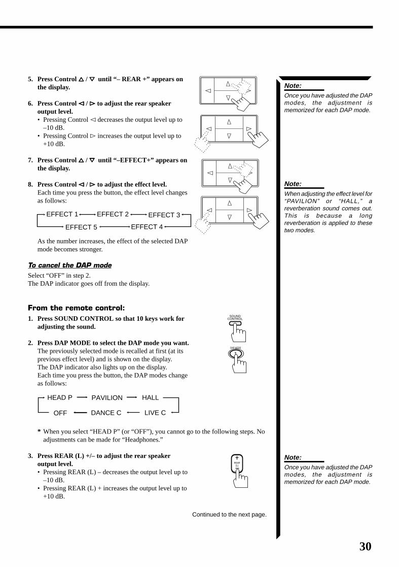
5. Press Control %%%%% / fififififi until “– REAR +” appears onthe display.
6. Press Control @@@@@ / ##### to adjust the rear speakeroutput level.• Pressing Control @ decreases the output level up to
–10 dB.• Pressing Control # increases the output level up to
+10 dB.
7. Press Control %%%%% / fififififi until “–EFFECT+” appears onthe display.
8. Press Control @@@@@ / ##### to adjust the effect level.Each time you press the button, the effect level changesas follows:
As the number increases, the effect of the selected DAPmode becomes stronger.
To cancel the DAP modeSelect “OFF” in step 2.The DAP indicator goes off from the display.
From the remote control:1. Press SOUND CONTROL so that 10 keys work for
adjusting the sound.
2. Press DAP MODE to select the DAP mode you want.The previously selected mode is recalled at first (at itsprevious effect level) and is shown on the display.The DAP indicator also lights up on the display.Each time you press the button, the DAP modes changeas follows:
* When you select “HEAD P” (or “OFF”), you cannot go to the following steps. Noadjustments can be made for “Headphones.”
3. Press REAR (L) +/– to adjust the rear speakeroutput level.• Pressing REAR (L) – decreases the output level up to
–10 dB.• Pressing REAR (L) + increases the output level up to
+10 dB.
EFFECT 1 EFFECT 2
EFFECT 4
EFFECT 3
EFFECT 5
Continued to the next page.
SOUND CONTROL
1DAP MODE
Note:Once you have adjusted the DAPmodes, the adjustment ismemorized for each DAP mode.
DANCE C LIVE C
PAVILION HALLHEAD P
OFF
REAR (L)
Note:Once you have adjusted the DAPmodes, the adjustment ismemorized for each DAP mode.
Note:When adjusting the effect level for“PAVILION” or “HALL,” areverberation sound comes out.This is because a longreverberation is applied to thesetwo modes.
RX-664VBK(J)_0119-001B_En.24-50 98.1.6, 11:29 AM30
31
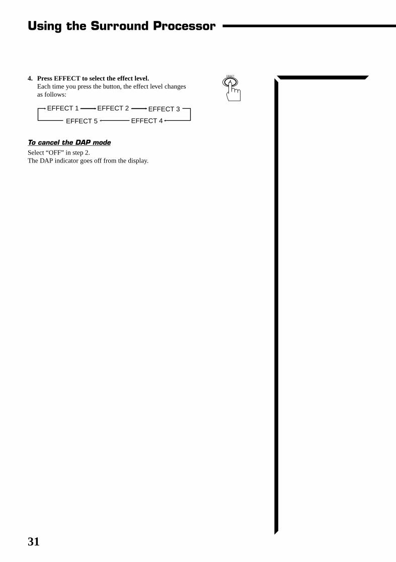
4. Press EFFECT to select the effect level.Each time you press the button, the effect level changesas follows:
To cancel the DAP modeSelect “OFF” in step 2.The DAP indicator goes off from the display.
EFFECT 1 EFFECT 2
EFFECT 4
EFFECT 3
EFFECT 5
Using the Surround Processor
4EFFECT
RX-664VBK(J)_0119-001B_En.24-50 98.1.6, 11:29 AM31
32
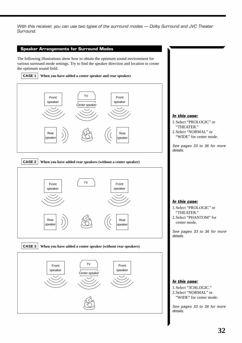
With this receiver, you can use two types of the surround modes — Dolby Surround and JVC TheaterSurround.
Speaker Arrangements for Surround Modes
The following illustrations show how to obtain the optimum sound environment forvarious surround mode settings. Try to find the speaker direction and location to createthe optimum sound field.
CASE 1 When you have added a center speaker and rear speakers
CASE 2 When you have added rear speakers (without a center speaker)
CASE 3 When you have added a center speaker (without rear speakers)
Frontspeaker
Frontspeaker
Rearspeaker
Rearspeaker
TV
Center speaker
Frontspeaker
Frontspeaker
Rearspeaker
Rearspeaker
TV
Frontspeaker
Frontspeaker
TV
Center speaker
In this case:1.Select “3CHLOGIC.”2.Select “NORMAL” or
“WIDE” for center mode.
See pages 33 to 36 for moredetails.
In this case:1.Select “PROLOGIC” or
“THEATER.”2.Select “PHANTOM” for
center mode.
See pages 33 to 36 for moredetails.
In this case:1.Select “PROLOGIC” or
“THEATER.”2.Select “NORMAL” or
“WIDE” for center mode.
See pages 33 to 36 for moredetails.
RX-664VBK(J)_0119-001B_En.24-50 98.1.6, 11:29 AM32
33
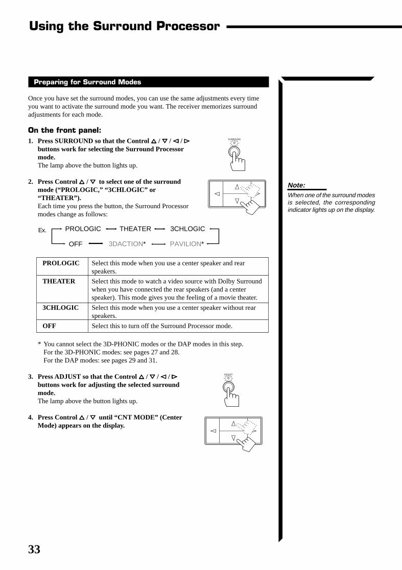
Preparing for Surround Modes
Once you have set the surround modes, you can use the same adjustments every timeyou want to activate the surround mode you want. The receiver memorizes surroundadjustments for each mode.
On the front panel:1. Press SURROUND so that the Control %%%%% / fififififi / @@@@@ / #####
buttons work for selecting the Surround Processormode.The lamp above the button lights up.
2. Press Control %%%%% / fififififi to select one of the surroundmode (“PROLOGIC,” “3CHLOGIC” or“THEATER”).Each time you press the button, the Surround Processormodes change as follows:
PROLOGIC Select this mode when you use a center speaker and rearspeakers.
THEATER Select this mode to watch a video source with Dolby Surroundwhen you have connected the rear speakers (and a centerspeaker). This mode gives you the feeling of a movie theater.
3CHLOGIC Select this mode when you use a center speaker without rearspeakers.
OFF Select this to turn off the Surround Processor mode.
* You cannot select the 3D-PHONIC modes or the DAP modes in this step.For the 3D-PHONIC modes: see pages 27 and 28.For the DAP modes: see pages 29 and 31.
3. Press ADJUST so that the Control %%%%% / fififififi / @@@@@ / #####buttons work for adjusting the selected surroundmode.The lamp above the button lights up.
4. Press Control %%%%% / fififififi until “CNT MODE” (CenterMode) appears on the display.
Using the Surround Processor
SURROUND
PROLOGIC THEATER
PAVILION*
3CHLOGIC
3DACTION*OFF
Ex.
Note:When one of the surround modesis selected, the correspondingindicator lights up on the display.
ADJUST
RX-664VBK(J)_0119-001B_En.24-50 98.1.6, 11:29 AM33
34
Notes:• No test tone comes out of the
rear speakers when you haveselected “3CHLOGIC.”
• No test tone comes out of thecenter speaker when you select“PHANTOM” for the centermode.
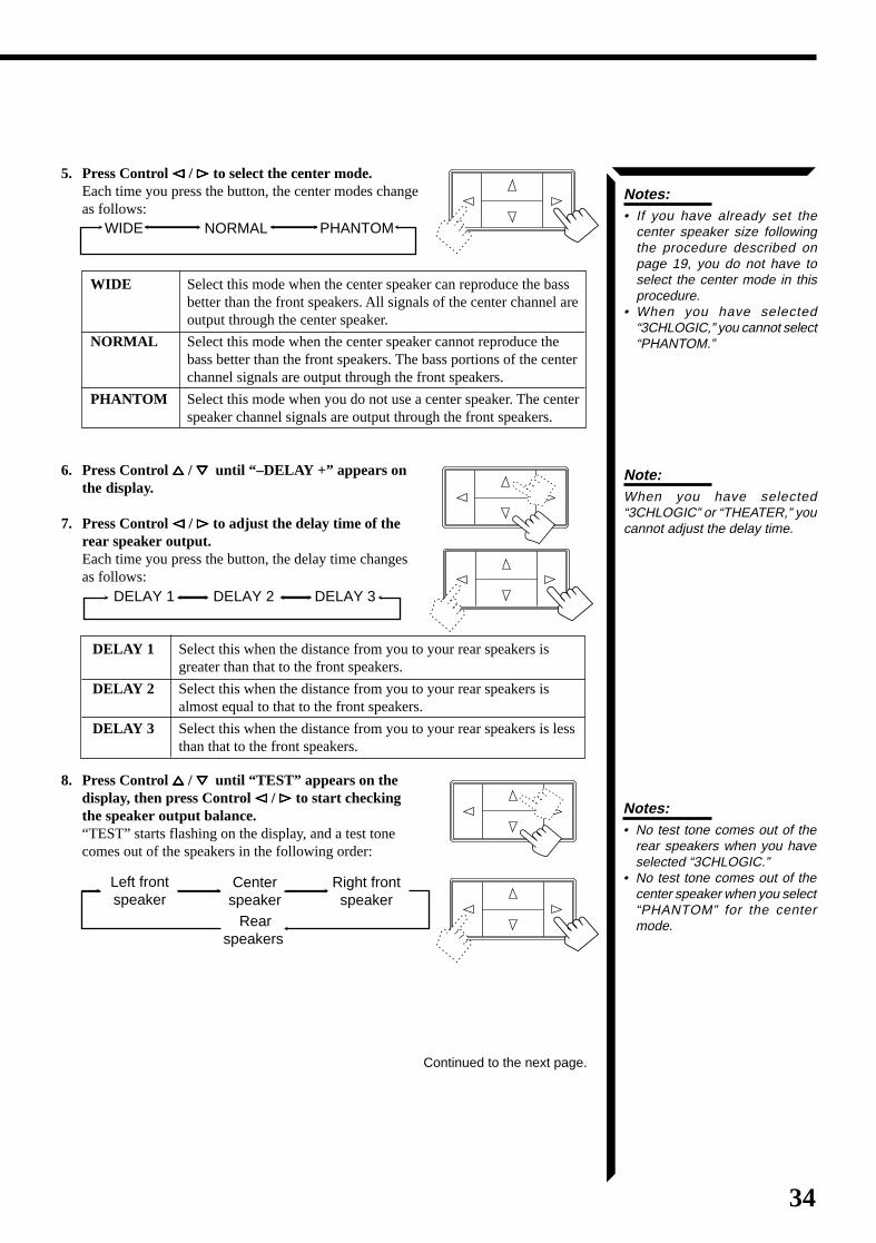
5. Press Control @@@@@ / ##### to select the center mode.Each time you press the button, the center modes changeas follows:
WIDE Select this mode when the center speaker can reproduce the bassbetter than the front speakers. All signals of the center channel areoutput through the center speaker.
NORMAL Select this mode when the center speaker cannot reproduce thebass better than the front speakers. The bass portions of the centerchannel signals are output through the front speakers.
PHANTOM Select this mode when you do not use a center speaker. The centerspeaker channel signals are output through the front speakers.
6. Press Control %%%%% / fififififi until “–DELAY +” appears onthe display.
7. Press Control @@@@@ / ##### to adjust the delay time of therear speaker output.Each time you press the button, the delay time changesas follows:
DELAY 1 Select this when the distance from you to your rear speakers isgreater than that to the front speakers.
DELAY 2 Select this when the distance from you to your rear speakers isalmost equal to that to the front speakers.
DELAY 3 Select this when the distance from you to your rear speakers is lessthan that to the front speakers.
8. Press Control %%%%% / fififififi until “TEST” appears on thedisplay, then press Control @@@@@ / ##### to start checkingthe speaker output balance.“TEST” starts flashing on the display, and a test tonecomes out of the speakers in the following order:
Notes:• If you have already set the
center speaker size followingthe procedure described onpage 19, you do not have toselect the center mode in thisprocedure.
• When you have selected“3CHLOGIC,” you cannot select“PHANTOM.”
DELAY 1 DELAY 2 DELAY 3
Left front speaker
Center speaker Rear
speakers
Right front speaker
Continued to the next page.
WIDE NORMAL PHANTOM
Note:When you have selected“3CHLOGIC” or “THEATER,” youcannot adjust the delay time.
RX-664VBK(J)_0119-001B_En.24-50 98.1.6, 11:29 AM34
35
Notes:• The sound levels of the left and
right rear speakers will be thesame.
• You cannot set the sound levelof the rear speakers when youhave selected “3CHLOGIC.”
• You cannot set the sound levelof the center speaker when youselect “PHANTOM” for thecenter mode.
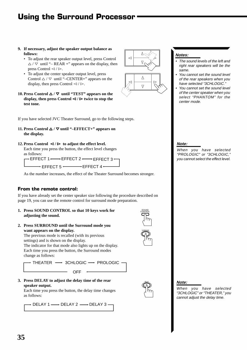
9. If necessary, adjust the speaker output balance asfollows:• To adjust the rear speaker output level, press Control
% / fi until “– REAR +” appears on the display, thenpress Control @ / #.
• To adjust the center speaker output level, pressControl % / fi until “–CENTER+” appears on thedisplay, then press Control @ / #.
10. Press Control %%%%% / fififififi until “TEST” appears on thedisplay, then press Control @@@@@ / ##### twice to stop thetest tone.
If you have selected JVC Theater Surround, go to the following steps.
11. Press Control %%%%% / fififififi until “–EFFECT+” appears onthe display.
12. Press Control @@@@@ / ##### to adjust the effect level.Each time you press the button, the effect level changesas follows:
As the number increases, the effect of the Theater Surround becomes stronger.
From the remote control:If you have already set the center speaker size following the procedure described onpage 19, you can use the remote control for surround mode preparation.
1. Press SOUND CONTROL so that 10 keys work foradjusting the sound.
2. Press SURROUND until the Surround mode youwant appears on the display.The previous mode is recalled (with its previoussettings) and is shown on the display.The indicator for that mode also lights up on the display.Each time you press the button, the Surround modeschange as follows:
3. Press DELAY to adjust the delay time of the rearspeaker output.Each time you press the button, the delay time changesas follows:
Using the Surround Processor
EFFECT 1 EFFECT 2
EFFECT 4
EFFECT 3
EFFECT 5
3SURROUND
SOUND CONTROL
5DELAY
DELAY 1 DELAY 2 DELAY 3
PROLOGICTHEATER 3CHLOGIC
OFF
Note:When you have selected“3CHLOGIC” or “THEATER,” youcannot adjust the delay time.
Note:When you have selected“PROLOGIC” or “3CHLOGIC,”you cannot select the effect level.
RX-664VBK(J)_0119-001B_En.24-50 98.1.6, 11:29 AM35
36
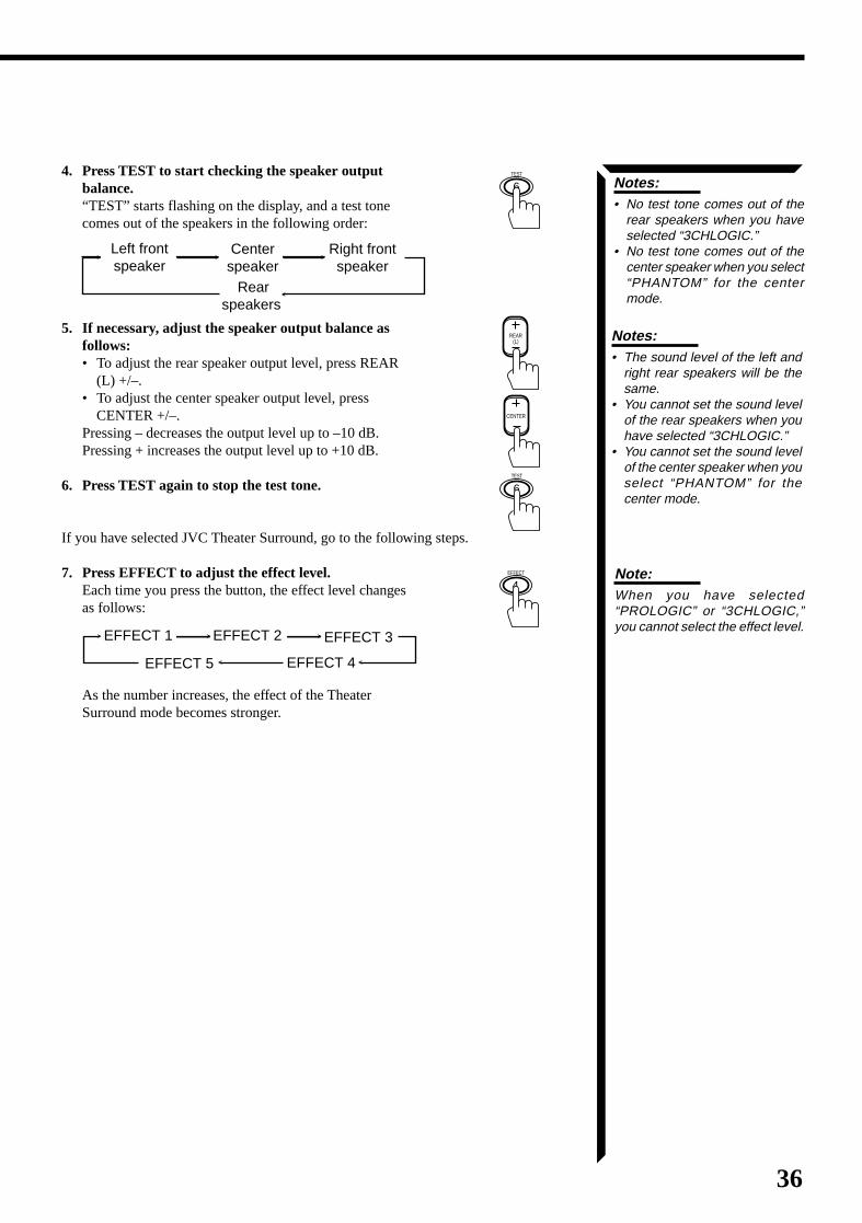
4. Press TEST to start checking the speaker outputbalance.“TEST” starts flashing on the display, and a test tonecomes out of the speakers in the following order:
5. If necessary, adjust the speaker output balance asfollows:• To adjust the rear speaker output level, press REAR
(L) +/–.• To adjust the center speaker output level, press
CENTER +/–.Pressing – decreases the output level up to –10 dB.Pressing + increases the output level up to +10 dB.
6. Press TEST again to stop the test tone.
If you have selected JVC Theater Surround, go to the following steps.
7. Press EFFECT to adjust the effect level.Each time you press the button, the effect level changesas follows:
As the number increases, the effect of the TheaterSurround mode becomes stronger.
Left front speaker
Center speaker Rear
speakers
Right front speaker
Notes:• The sound level of the left and
right rear speakers will be thesame.
• You cannot set the sound levelof the rear speakers when youhave selected “3CHLOGIC.”
• You cannot set the sound levelof the center speaker when youselect “PHANTOM” for thecenter mode.
EFFECT 1 EFFECT 2
EFFECT 4
EFFECT 3
EFFECT 5
Notes:• No test tone comes out of the
rear speakers when you haveselected “3CHLOGIC.”
• No test tone comes out of thecenter speaker when you select“PHANTOM” for the centermode.
4EFFECT
6TEST
CENTER
REAR (L)
6TEST
Note:When you have selected“PROLOGIC” or “3CHLOGIC,”you cannot select the effect level.
RX-664VBK(J)_0119-001B_En.24-50 98.1.6, 11:29 AM36
37
Using the Surround Processor
Using Surround Modes
Once you have adjusted the surround mode you can use the same adjustments everytime you want to enjoy Surround modes.
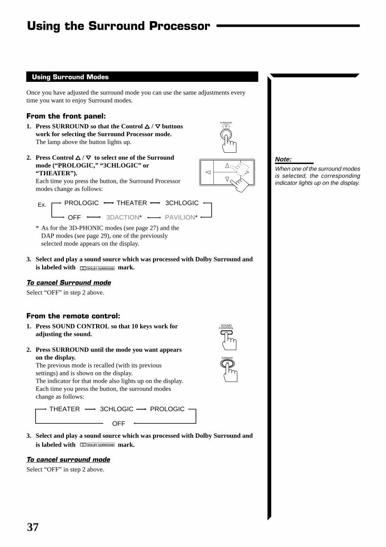
From the front panel:1. Press SURROUND so that the Control %%%%% / fififififi buttons
work for selecting the Surround Processor mode.The lamp above the button lights up.
2. Press Control %%%%% / fififififi to select one of the Surroundmode (“PROLOGIC,” “3CHLOGIC” or“THEATER”).Each time you press the button, the Surround Processormodes change as follows:
* As for the 3D-PHONIC modes (see page 27) and theDAP modes (see page 29), one of the previouslyselected mode appears on the display.
3. Select and play a sound source which was processed with Dolby Surround andis labeled with DOLBY SURROUND mark.
To cancel Surround modeSelect “OFF” in step 2 above.
From the remote control:1. Press SOUND CONTROL so that 10 keys work for
adjusting the sound.
2. Press SURROUND until the mode you want appearson the display.The previous mode is recalled (with its previoussettings) and is shown on the display.The indicator for that mode also lights up on the display.Each time you press the button, the surround modeschange as follows:
3. Select and play a sound source which was processed with Dolby Surround andis labeled with DOLBY SURROUND mark.
To cancel surround modeSelect “OFF” in step 2 above.
PROLOGIC THEATER
PAVILION*
3CHLOGIC
3DACTION*OFF
Ex.
SURROUND
Note:When one of the surround modesis selected, the correspondingindicator lights up on the display.
SOUND CONTROL
3SURROUND
PROLOGICTHEATER 3CHLOGIC
OFF
RX-664VBK(J)_0119-001B_En.24-50 98.1.6, 11:30 AM37
38
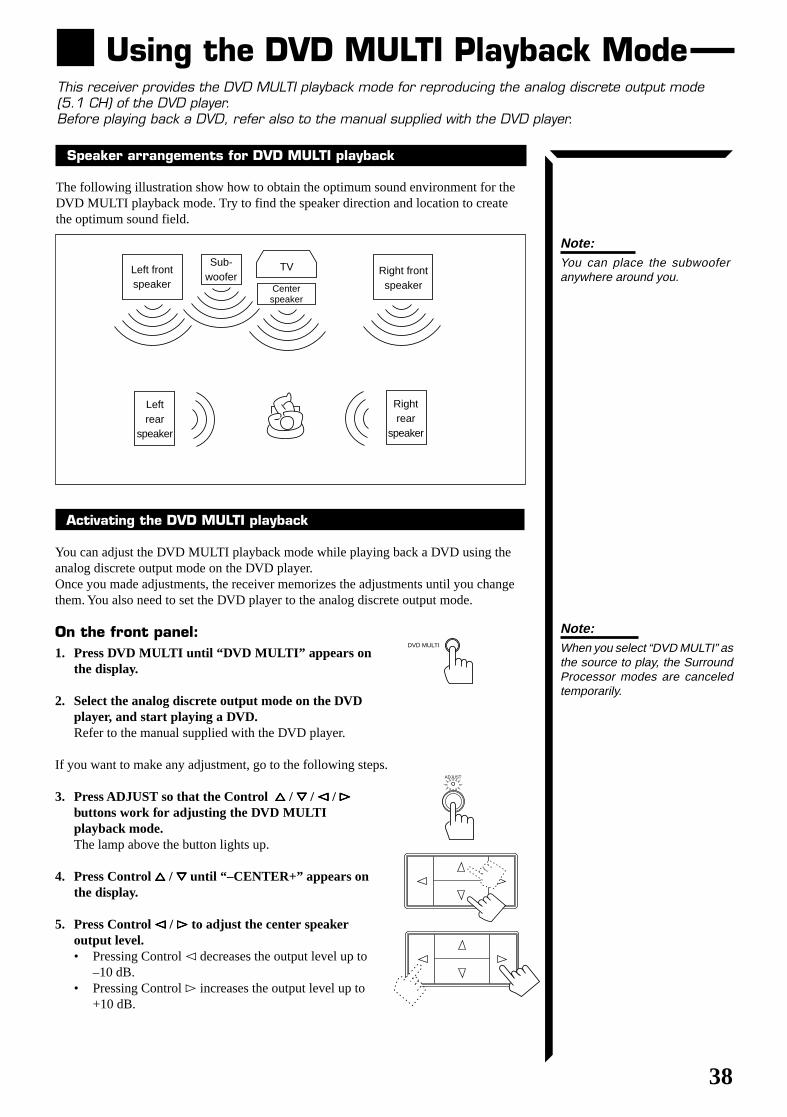
Using the DVD MULTI Playback ModeThis receiver provides the DVD MULTI playback mode for reproducing the analog discrete output mode(5.1 CH) of the DVD player.Before playing back a DVD, refer also to the manual supplied with the DVD player.
Left frontspeaker
Sub-woofer
TV Right frontspeaker
Leftrear
speaker
Rightrear
speaker
Centerspeaker
Note:You can place the subwooferanywhere around you.
Activating the DVD MULTI playback
You can adjust the DVD MULTI playback mode while playing back a DVD using theanalog discrete output mode on the DVD player.Once you made adjustments, the receiver memorizes the adjustments until you changethem. You also need to set the DVD player to the analog discrete output mode.
On the front panel:1. Press DVD MULTI until “DVD MULTI” appears on
the display.
2. Select the analog discrete output mode on the DVDplayer, and start playing a DVD.Refer to the manual supplied with the DVD player.
If you want to make any adjustment, go to the following steps.
3. Press ADJUST so that the Control %%%%% / fififififi / @@@@@ / #####buttons work for adjusting the DVD MULTIplayback mode.The lamp above the button lights up.
4. Press Control %%%%% / fififififi until “–CENTER+” appears onthe display.
5. Press Control @@@@@ / ##### to adjust the center speakeroutput level.• Pressing Control @ decreases the output level up to
–10 dB.• Pressing Control # increases the output level up to
+10 dB.
ADJUST
DVD MULTI
Note:When you select “DVD MULTI” asthe source to play, the SurroundProcessor modes are canceledtemporarily.
Speaker arrangements for DVD MULTI playback
The following illustration show how to obtain the optimum sound environment for theDVD MULTI playback mode. Try to find the speaker direction and location to createthe optimum sound field.
RX-664VBK(J)_0119-001B_En.24-50 98.1.6, 11:30 AM38
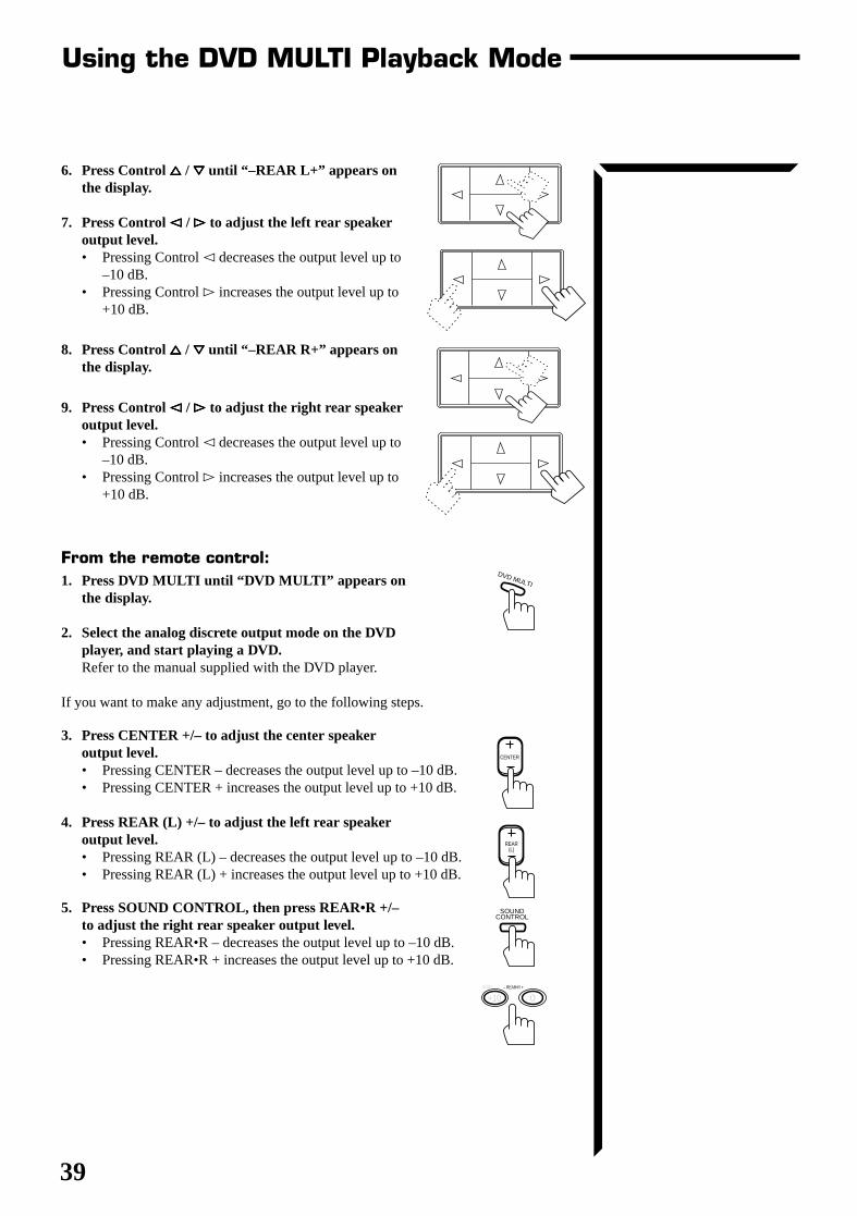
39
Using the DVD MULTI Playback Mode
6. Press Control %%%%% / fififififi until “–REAR L+” appears onthe display.
7. Press Control @@@@@ / ##### to adjust the left rear speakeroutput level.• Pressing Control @ decreases the output level up to
–10 dB.• Pressing Control # increases the output level up to
+10 dB.
8. Press Control %%%%% / fififififi until “–REAR R+” appears onthe display.
9. Press Control @@@@@ / ##### to adjust the right rear speakeroutput level.• Pressing Control @ decreases the output level up to
–10 dB.• Pressing Control # increases the output level up to
+10 dB.
From the remote control:1. Press DVD MULTI until “DVD MULTI” appears on
the display.
2. Select the analog discrete output mode on the DVDplayer, and start playing a DVD.Refer to the manual supplied with the DVD player.
If you want to make any adjustment, go to the following steps.
3. Press CENTER +/– to adjust the center speakeroutput level.• Pressing CENTER – decreases the output level up to –10 dB.• Pressing CENTER + increases the output level up to +10 dB.
4. Press REAR (L) +/– to adjust the left rear speakeroutput level.• Pressing REAR (L) – decreases the output level up to –10 dB.• Pressing REAR (L) + increases the output level up to +10 dB.
5. Press SOUND CONTROL, then press REAR•R +/–to adjust the right rear speaker output level.• Pressing REAR•R – decreases the output level up to –10 dB.• Pressing REAR•R + increases the output level up to +10 dB.
DVD MULTI
CENTER
REAR (L)
SOUND CONTROL
100+
0+10– REAR•R +
RX-664VBK(J)_0119-001B_En.24-50 98.1.6, 11:30 AM39
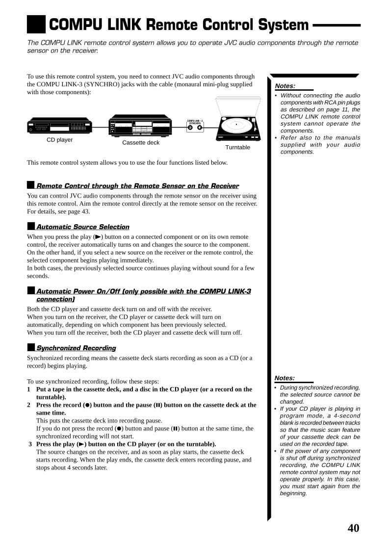
40
COMPU LINK Remote Control SystemThe COMPU LINK remote control system allows you to operate JVC audio components through the remotesensor on the receiver.
To use this remote control system, you need to connect JVC audio components throughthe COMPU LINK-3 (SYNCHRO) jacks with the cable (monaural mini-plug suppliedwith those components):
This remote control system allows you to use the four functions listed below.
Remote Control through the Remote Sensor on the ReceiverYou can control JVC audio components through the remote sensor on the receiver usingthis remote control. Aim the remote control directly at the remote sensor on the receiver.For details, see page 43.
Automatic Source SelectionWhen you press the play (33333) button on a connected component or on its own remotecontrol, the receiver automatically turns on and changes the source to the component.On the other hand, if you select a new source on the receiver or the remote control, theselected component begins playing immediately.In both cases, the previously selected source continues playing without sound for a fewseconds.
Automatic Power On/Off (only possible with the COMPU LINK-3connection)
Both the CD player and cassette deck turn on and off with the receiver.When you turn on the receiver, the CD player or cassette deck will turn onautomatically, depending on which component has been previously selected.When you turn off the receiver, both the CD player and cassette deck will turn off.
Synchronized RecordingSynchronized recording means the cassette deck starts recording as soon as a CD (or arecord) begins playing.
To use synchronized recording, follow these steps:1 Put a tape in the cassette deck, and a disc in the CD player (or a record on the
turntable).2 Press the record (¶) button and the pause (8) button on the cassette deck at the
same time.This puts the cassette deck into recording pause.If you do not press the record (¶) button and pause (8) button at the same time, thesynchronized recording will not start.
3 Press the play (3) button on the CD player (or on the turntable).The source changes on the receiver, and as soon as play starts, the cassette deckstarts recording. When the play ends, the cassette deck enters recording pause, andstops about 4 seconds later.
Notes:• Without connecting the audio
components with RCA pin plugsas described on page 11, theCOMPU LINK remote controlsystem cannot operate thecomponents.
• Refer also to the manualssupplied with your audiocomponents.
Notes:• During synchronized recording,
the selected source cannot bechanged.
• If your CD player is playing inprogram mode, a 4-secondblank is recorded between tracksso that the music scan featureof your cassette deck can beused on the recorded tape.
• If the power of any componentis shut off during synchronizedrecording, the COMPU LINKremote control system may notoperate properly. In this case,you must start again from thebeginning.
CD player Cassette deckTurntable
COMPU LINK – 3 (SYNCHRO)
RX-664VBK(J)_0119-001B_En.24-50 98.1.6, 11:30 AM40
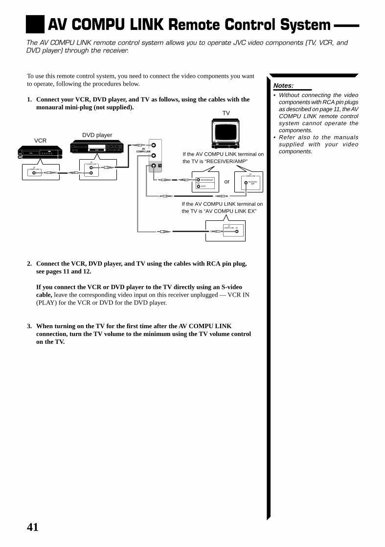
41
AV COMPU LINK Remote Control SystemThe AV COMPU LINK remote control system allows you to operate JVC video components (TV, VCR, andDVD player) through the receiver.
Notes:• Without connecting the video
components with RCA pin plugsas described on page 11, the AVCOMPU LINK remote controlsystem cannot operate thecomponents.
• Refer also to the manualssupplied with your videocomponents.
To use this remote control system, you need to connect the video components you wantto operate, following the procedures below.
1. Connect your VCR, DVD player, and TV as follows, using the cables with themonaural mini-plug (not supplied).
2. Connect the VCR, DVD player, and TV using the cables with RCA pin plug,see pages 11 and 12.
If you connect the VCR or DVD player to the TV directly using an S-videocable, leave the corresponding video input on this receiver unplugged — VCR IN(PLAY) for the VCR or DVD for the DVD player.
3. When turning on the TV for the first time after the AV COMPU LINKconnection, turn the TV volume to the minimum using the TV volume controlon the TV.
If the AV COMPU LINK terminal onthe TV is “AV COMPU LINK EX”
If the AV COMPU LINK terminal onthe TV is “RECEIVER/AMP”
TV
DVD playerVCR
or
AV COMPU LINK
RECEIVER/ AMP
AV COMPU LINK
AV COMPU LINK
VHS
AV COMPU LINK
DVD
AV COMPU LINK EX
RECEIVER/AMP
(VCR)EX
RX-664VBK(J)_0119-001B_En.24-50 98.1.6, 11:30 AM41
42
Note:Refer also to the manual suppliedwith your video components.
The AV COMPU LINK remote control system allows you to use the five basic functionslisted below.
Remote Control of the TV, DVD player, and VCR Using ThisRemote Control
See page 44 for details.For the DVD player and the VCR:• Aim the remote control directly at the remote sensor on the each component.For the TV having AV COMPU LINK terminal “RECEIVER/AMP”:• Aim the remote control directly at the remote sensor on the receiver when
operating the TV.For the TV having AV COMPU LINK terminal “AV COMPU LINK EX”:• Aim the remote control directly at the remote sensor on the TV when operating the
TV.
One-Touch Video PlaySimply by inserting a video cassette without its safety tab into the VCR, you canactivate the video playback without setting other switches manually.The receiver automatically turns on and changes the source to the VCR.The TV automatically turns on and changes the input mode to the correct position sothat you can view the VCR playback.When you insert a video cassette with its safety tab, press the play (33333) button on theVCR or on the remote control. So, you can get the same result.
One-Touch DVD PlaySimply by starting playback on the DVD player, you can enjoy the DVD playbackwithout setting other switches manually.The receiver automatically turns on and changes the source to “DVD” or “DVDMULTI”—DVD playback mode is automatically selected when a disc played in stereo,while DVD MULTI playback mode is automatically selected when a disc is played backusing the analog discrete output mode on the DVD player or the audio output setting ofthe DVD player is mixed to two front channels.The TV automatically turns on and changes the input mode to the position so that youcan view the playback picture.
Automatic Selection of TV’s Input Mode• When you select TV SOUND as the source to play through the receiver, the TV
automatically changes the input mode to the TV tuner.So, you can watch TV, without changing the input mode on the TV.
• When you select “DVD,” “DVD MULTI” or “VCR” as the source to play on thereceiver, the TV automatically changes the input mode to the correct position (eitherVideo Input 1 or 2) so that you can watch the playback picture.
Automatic Power On/OffThe TV, VCR, and DVD player turn on and off along with the receiver.When you turn on the receiver;• If the previously selected source is “VCR,” the TV and VCR will turn on
automatically.• If the previously selected source is “TV SOUND,” only the TV will turn on
automatically.• If the previously selected source is “DVD” or “DVD MULTI,” the TV and DVD
player will turn on automatically.When you turn off the receiver, the TV, VCR, and DVD player will turn off.
Note:If you turn off the receiver whilerecording on the VCR, the VCRwill not turn off, but continuerecording.
Note:When you start playing a disc of5.1 ch surround, “DVD MULTI” willbe selected though you havepreviously selected “DVD.” Youcan change it to “DVD” afterplayback starts.
RX-664VBK(J)_0119-001B_En.24-50 98.1.6, 11:30 AM42
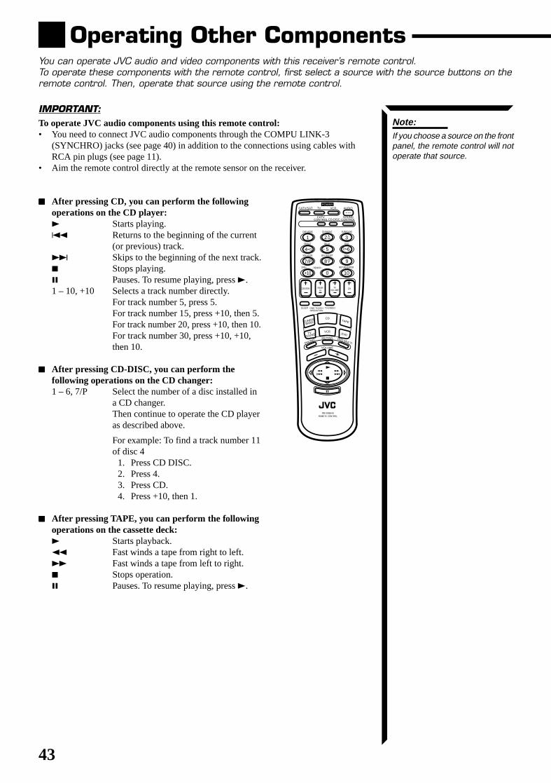
43
Operating Other ComponentsYou can operate JVC audio and video components with this receiver’s remote control.To operate these components with the remote control, first select a source with the source buttons on theremote control. Then, operate that source using the remote control.
IMPORTANT:To operate JVC audio components using this remote control:• You need to connect JVC audio components through the COMPU LINK-3
(SYNCHRO) jacks (see page 40) in addition to the connections using cables withRCA pin plugs (see page 11).
• Aim the remote control directly at the remote sensor on the receiver.
77777 After pressing CD, you can perform the followingoperations on the CD player:3 Starts playing.4 Returns to the beginning of the current
(or previous) track.¢ Skips to the beginning of the next track.7 Stops playing.8 Pauses. To resume playing, press 3.1 – 10, +10 Selects a track number directly.
For track number 5, press 5.For track number 15, press +10, then 5.For track number 20, press +10, then 10.For track number 30, press +10, +10,then 10.
77777 After pressing CD-DISC, you can perform thefollowing operations on the CD changer:1 – 6, 7/P Select the number of a disc installed in
a CD changer.Then continue to operate the CD playeras described above.
For example: To find a track number 11of disc 4
1. Press CD DISC.2. Press 4.3. Press CD.4. Press +10, then 1.
77777 After pressing TAPE, you can perform the followingoperations on the cassette deck:3 Starts playback.1 Fast winds a tape from right to left.¡ Fast winds a tape from left to right.7 Stops operation.8 Pauses. To resume playing, press 3.
Note:If you choose a source on the frontpanel, the remote control will notoperate that source.
CATV/SAT
ONE TOUCH OPERATION
TV/VIDEO
TV
CATV CONTROLCD-DISC
SOUND CONTROL
VCR AUDIO
CENTER REAR (L)
CHTV VOLUME
100+ RETURN/ENTER
321
654
98
0
7/P
+10 10
PHONO
CD
VCR
MUTING
VOLUME
DVD MULTI
TAPE
DVD
POWER
TUNER/
BAND
TV SOUND
RM-SR664U REMOTE CONTROL
DAP MODE 3D-PHONIC SURROUND
EFFECT DELAY TEST
SEA MODE SEA PRESET MENU
– REAR•R +
SLEEP
RX-664VBK(J)_0119-001B_En.24-50 98.1.6, 11:30 AM43
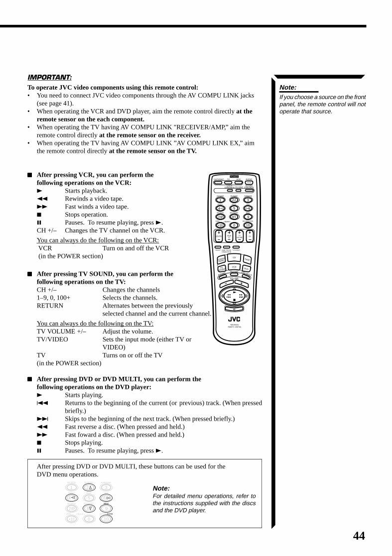
44
IMPORTANT:To operate JVC video components using this remote control:• You need to connect JVC video components through the AV COMPU LINK jacks
(see page 41).• When operating the VCR and DVD player, aim the remote control directly at the
remote sensor on the each component.• When operating the TV having AV COMPU LINK "RECEIVER/AMP,” aim the
remote control directly at the remote sensor on the receiver.• When operating the TV having AV COMPU LINK ”AV COMPU LINK EX,” aim
the remote control directly at the remote sensor on the TV.
77777 After pressing VCR, you can perform thefollowing operations on the VCR:3 Starts playback.1 Rewinds a video tape.¡ Fast winds a video tape.7 Stops operation.8 Pauses. To resume playing, press 3.CH +/– Changes the TV channel on the VCR.
You can always do the following on the VCR: VCR Turn on and off the VCR (in the POWER section)
77777 After pressing TV SOUND, you can perform thefollowing operations on the TV:CH +/– Changes the channels1–9, 0, 100+ Selects the channels.RETURN Alternates between the previously
selected channel and the current channel.
You can always do the following on the TV:TV VOLUME +/– Adjust the volume.TV/VIDEO Sets the input mode (either TV or
VIDEO)TV Turns on or off the TV(in the POWER section)
77777 After pressing DVD or DVD MULTI, you can perform thefollowing operations on the DVD player:3 Starts playing.4 Returns to the beginning of the current (or previous) track. (When pressed
briefly.)¢ Skips to the beginning of the next track. (When pressed briefly.)1 Fast reverse a disc. (When pressed and held.)¡ Fast foward a disc. (When pressed and held.)7 Stops playing.8 Pauses. To resume playing, press 3.
After pressing DVD or DVD MULTI, these buttons can be used for theDVD menu operations.
Note:If you choose a source on the frontpanel, the remote control will notoperate that source.
100+ RETURN/ENTER
321
65
98
0
7/P
+10 10
DAP MODE 3D-PHONIC SURROUND
– REAR•R +
EFFECT DELAY TEST
SEA MODE SEA PRESET MENU
4
Note:For detailed menu operations, refer tothe instructions supplied with the discsand the DVD player.
CATV/SAT
ONE TOUCH OPERATION
TV/VIDEO
TV
CATV CONTROLCD-DISC
SOUND CONTROL
VCR AUDIO
CENTER REAR (L)
CHTV VOLUME
100+ RETURN/ENTER
321
654
98
0
7/P
+10 10
PHONO
CD
VCR
MUTING
VOLUME
DVD MULTI
TAPE
DVD
POWER
TUNER/
BAND
TV SOUND
RM-SR664U REMOTE CONTROL
DAP MODE 3D-PHONIC SURROUND
EFFECT DELAY TEST
SEA MODE SEA PRESET MENU
– REAR•R +
SLEEP
RX-664VBK(J)_0119-001B_En.24-50 98.1.6, 11:30 AM44
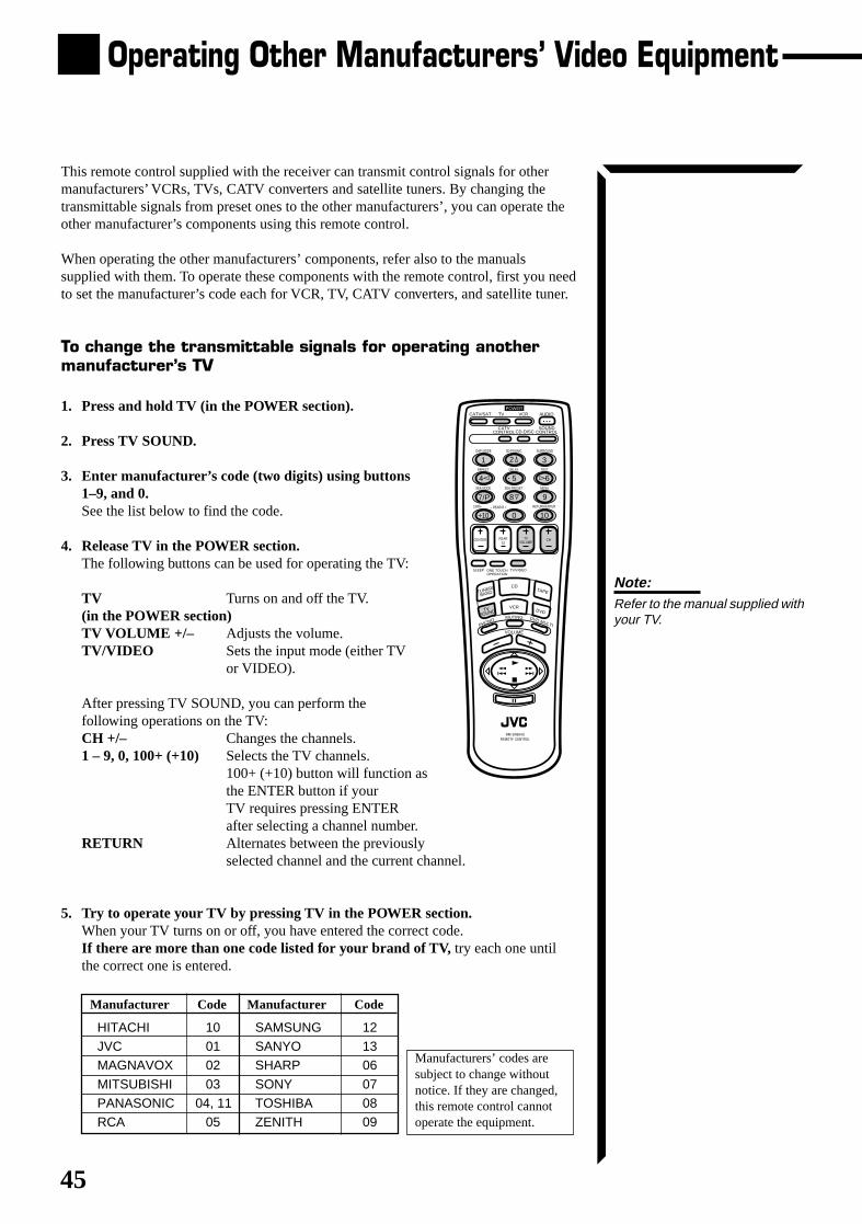
45
Operating Other Manufacturers’ Video Equipment
This remote control supplied with the receiver can transmit control signals for othermanufacturers’ VCRs, TVs, CATV converters and satellite tuners. By changing thetransmittable signals from preset ones to the other manufacturers’, you can operate theother manufacturer’s components using this remote control.
When operating the other manufacturers’ components, refer also to the manualssupplied with them. To operate these components with the remote control, first you needto set the manufacturer’s code each for VCR, TV, CATV converters, and satellite tuner.
To change the transmittable signals for operating anothermanufacturer’s TV
1. Press and hold TV (in the POWER section).
2. Press TV SOUND.
3. Enter manufacturer’s code (two digits) using buttons1–9, and 0.See the list below to find the code.
4. Release TV in the POWER section.The following buttons can be used for operating the TV:
TV Turns on and off the TV.(in the POWER section)TV VOLUME +/– Adjusts the volume.TV/VIDEO Sets the input mode (either TV
or VIDEO).
After pressing TV SOUND, you can perform thefollowing operations on the TV:CH +/– Changes the channels.1 – 9, 0, 100+ (+10) Selects the TV channels.
100+ (+10) button will function asthe ENTER button if yourTV requires pressing ENTERafter selecting a channel number.
RETURN Alternates between the previouslyselected channel and the current channel.
5. Try to operate your TV by pressing TV in the POWER section.When your TV turns on or off, you have entered the correct code.If there are more than one code listed for your brand of TV, try each one untilthe correct one is entered.
Note:Refer to the manual supplied withyour TV.
Manufacturer Code Manufacturer Code
HITACHI 10 SAMSUNG 12 JVC 01 SANYO 13 MAGNAVOX 02 SHARP 06
MITSUBISHI 03 SONY 07 PANASONIC 04, 11 TOSHIBA 08 RCA 05 ZENITH 09
CATV/SAT
ONE TOUCH OPERATION
TV/VIDEO
TV
CATV CONTROLCD-DISC
SOUND CONTROL
VCR AUDIO
CENTER REAR (L)
CHTV VOLUME
100+ RETURN/ENTER
321
654
98
0
7/P
+10 10
PHONO
CD
VCR
MUTING
VOLUME
DVD MULTI
TAPE
DVD
POWER
TUNER/
BAND
TV SOUND
RM-SR664U REMOTE CONTROL
DAP MODE 3D-PHONIC SURROUND
EFFECT DELAY TEST
SEA MODE SEA PRESET MENU
– REAR•R +
SLEEP
Manufacturers’ codes aresubject to change withoutnotice. If they are changed,this remote control cannotoperate the equipment.
RX-664VBK(J)_0119-001B_En.24-50 98.1.6, 11:30 AM45
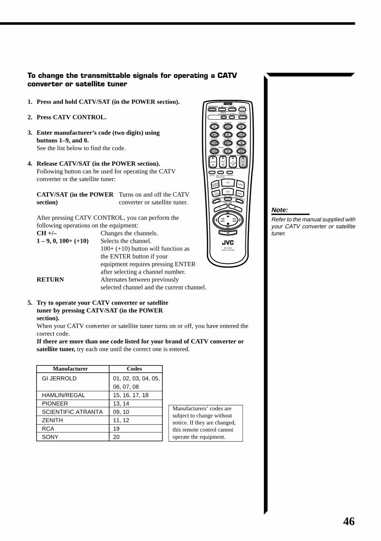
46
To change the transmittable signals for operating a CATVconverter or satellite tuner
1. Press and hold CATV/SAT (in the POWER section).
2. Press CATV CONTROL.
3. Enter manufacturer’s code (two digits) usingbuttons 1–9, and 0.See the list below to find the code.
4. Release CATV/SAT (in the POWER section).Following button can be used for operating the CATVconverter or the satellite tuner:
CATV/SAT (in the POWER Turns on and off the CATVsection) converter or satellite tuner.
After pressing CATV CONTROL, you can perform thefollowing operations on the equipment:CH +/– Changes the channels.1 – 9, 0, 100+ (+10) Selects the channel.
100+ (+10) button will function asthe ENTER button if yourequipment requires pressing ENTERafter selecting a channel number.
RETURN Alternates between previouslyselected channel and the current channel.
5. Try to operate your CATV converter or satellitetuner by pressing CATV/SAT (in the POWERsection).When your CATV converter or satellite tuner turns on or off, you have entered thecorrect code.If there are more than one code listed for your brand of CATV converter orsatellite tuner, try each one until the correct one is entered.
Note:Refer to the manual supplied withyour CATV converter or satellitetuner.
Manufacturer Codes
GI JERROLD 01, 02, 03, 04, 05,06, 07, 08
HAMLIN/REGAL 15, 16, 17, 18
PIONEER 13, 14SCIENTIFIC ATRANTA 09, 10ZENITH 11, 12
RCA 19SONY 20
Manufacturers’ codes aresubject to change withoutnotice. If they are changed,this remote control cannotoperate the equipment.
CATV/SAT
ONE TOUCH OPERATION
TV/VIDEO
TV
CATV CONTROLCD-DISC
SOUND CONTROL
VCR AUDIO
CENTER REAR (L)
CHTV VOLUME
100+ RETURN/ENTER
321
654
98
0
7/P
+10 10
PHONO
CD
VCR
MUTING
VOLUME
DVD MULTI
TAPE
DVD
POWER
TUNER/
BAND
TV SOUND
RM-SR664U REMOTE CONTROL
DAP MODE 3D-PHONIC SURROUND
EFFECT DELAY TEST
SEA MODE SEA PRESET MENU
– REAR•R +
SLEEP
RX-664VBK(J)_0119-001B_En.24-50 98.1.6, 11:30 AM46
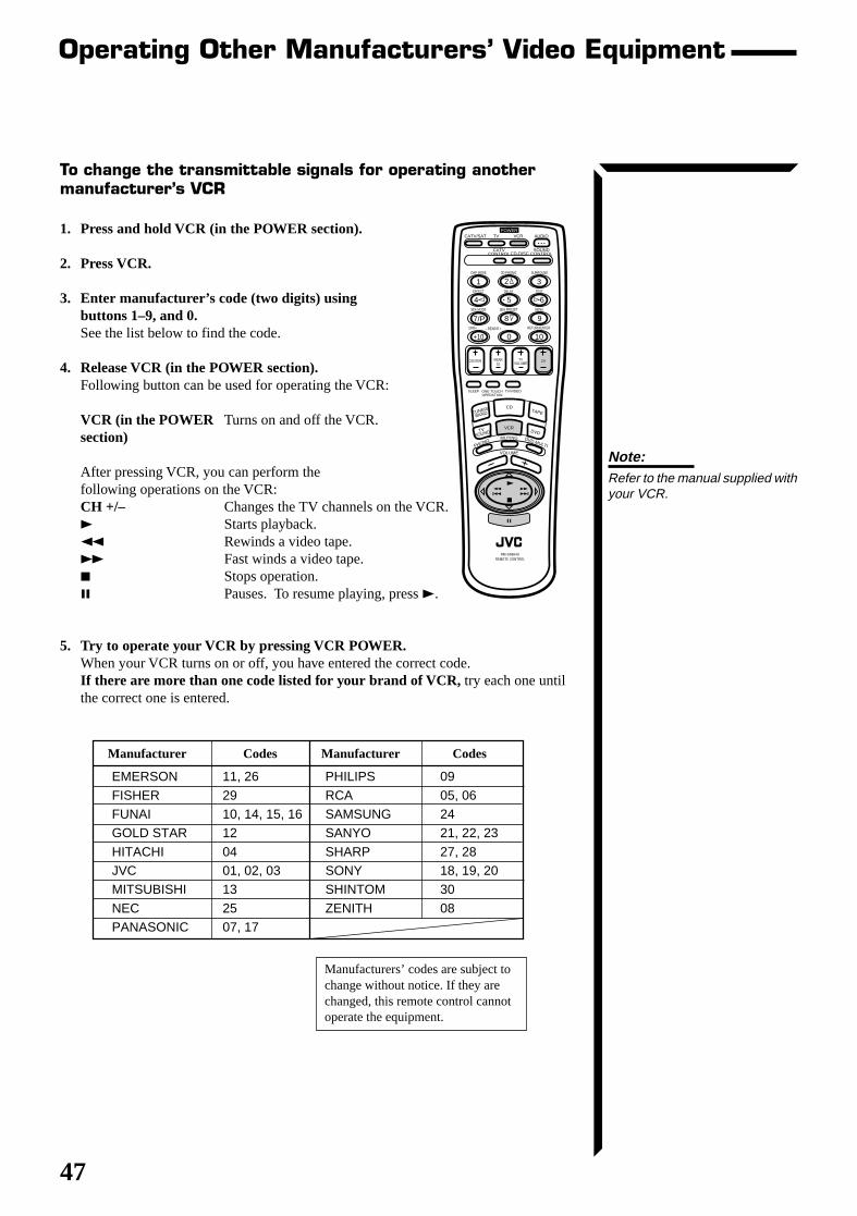
47
Note:Refer to the manual supplied withyour VCR.
Operating Other Manufacturers’ Video Equipment
To change the transmittable signals for operating anothermanufacturer’s VCR
1. Press and hold VCR (in the POWER section).
2. Press VCR.
3. Enter manufacturer’s code (two digits) usingbuttons 1–9, and 0.See the list below to find the code.
4. Release VCR (in the POWER section).Following button can be used for operating the VCR:
VCR (in the POWER Turns on and off the VCR.section)
After pressing VCR, you can perform thefollowing operations on the VCR:CH +/– Changes the TV channels on the VCR.3 Starts playback.1 Rewinds a video tape.¡ Fast winds a video tape.7 Stops operation.8 Pauses. To resume playing, press 3.
5. Try to operate your VCR by pressing VCR POWER.When your VCR turns on or off, you have entered the correct code.If there are more than one code listed for your brand of VCR, try each one untilthe correct one is entered.
Manufacturer Codes Manufacturer Codes
EMERSON 11, 26 PHILIPS 09
FISHER 29 RCA 05, 06FUNAI 10, 14, 15, 16 SAMSUNG 24GOLD STAR 12 SANYO 21, 22, 23
HITACHI 04 SHARP 27, 28JVC 01, 02, 03 SONY 18, 19, 20MITSUBISHI 13 SHINTOM 30
NEC 25 ZENITH 08PANASONIC 07, 17
Manufacturers’ codes are subject tochange without notice. If they arechanged, this remote control cannotoperate the equipment.
CATV/SAT
ONE TOUCH OPERATION
TV/VIDEO
TV
CATV CONTROLCD-DISC
SOUND CONTROL
VCR AUDIO
CENTER REAR (L)
CHTV VOLUME
100+ RETURN/ENTER
321
654
98
0
7/P
+10 10
PHONO
CD
VCR
MUTING
VOLUME
DVD MULTI
TAPE
DVD
POWER
TUNER/
BAND
TV SOUND
RM-SR664U REMOTE CONTROL
DAP MODE 3D-PHONIC SURROUND
EFFECT DELAY TEST
SEA MODE SEA PRESET MENU
– REAR•R +
SLEEP
RX-664VBK(J)_0119-001B_En.24-50 98.1.6, 11:30 AM47
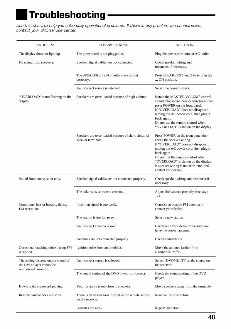
48
TroubleshootingUse this chart to help you solve daily operational problems. If there is any problem you cannot solve,contact your JVC service center.
SOLUTION
Plug the power cord into an AC outlet.
Check speaker wiring andreconnect if necessary.
Press SPEAKERS 1 and 2 to set it in the_ ON position.
Select the correct source.
Rotate the MASTER VOLUME controlcounterclockwise three or four times thenpress POWER on the front panel.If “OVERLOAD” does not disappear,unplug the AC power cord, then plug itback again.Do not use the remote control when“OVERLOAD” is shown on the display.
Press POWER on the front panel thencheck the speaker wiring.If “OVERLOAD” does not disappear,unplug the AC power cord, then plug itback again.Do not use the remote control when“OVERLOAD” is shown on the display.If speaker wiring is not short circuited,contact your dealer.
Check speaker wiring and reconnect ifnecessary.
Adjust the balance properly (see page17).
Connect an outside FM antenna orcontact your dealer.
Select a new station
Check with your dealer to be sure youhave the correct antenna.
Check connections.
Move the antenna farther fromautomobile traffic.
Select “DVDMULTI” as the source onthe receiver.
Check the sound setting of the DVDplayer.
Move speakers away from the turntable.
Remove the obstruction.
Replace batteries.
PROBLEM
The display does not light up.
No sound from speakers.
“OVERLOAD” starts flashing on thedisplay.
Sound from one speaker only.
Continuous hiss or buzzing duringFM reception.
Occasional cracking noise during FMreception.
The analog discrete output sound ofthe DVD player cannot bereproduced correctly.
Howling during record playing.
Remote control does not work.
POSSIBLE CAUSE
The power cord is not plugged in.
Speaker signal cables are not connected.
The SPEAKERS 1 and 2 buttons are not setcorrectly.
An incorrect source is selected.
Speakers are over-loaded because of high volume.
Speakers are over-loaded because of short circuit ofspeaker terminals.
Speaker signal cables are not connected properly.
The balance is set to one extreme.
Incoming signal is too weak.
The station is too far away.
An incorrect antenna is used.
Antennas are not connected properly.
Ignition noise from automobiles.
An incorrect source is selected.
The sound setting of the DVD player is incorrect.
Your turntable is too close to speakers.
There is an obstruction in front of the remote sensoron the receiver.
Batteries are weak.
RX-664VBK(J)_0119-001B_En.24-50 98.1.6, 11:30 AM48
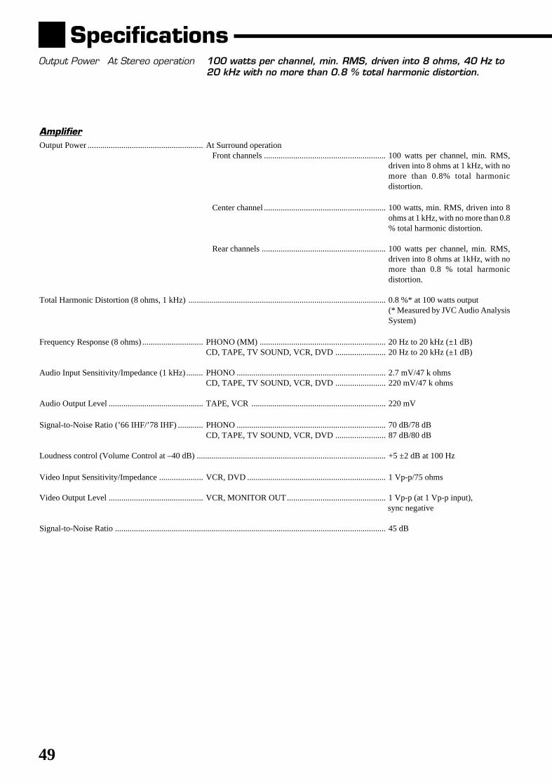
49
SpecificationsOutput Power At Stereo operation 100 watts per channel, min. RMS, driven into 8 ohms, 40 Hz to
20 kHz with no more than 0.8 % total harmonic distortion.
AmplifierOutput Power ....................................................... At Surround operation
Front channels .......................................................... 100 watts per channel, min. RMS,driven into 8 ohms at 1 kHz, with nomore than 0.8% total harmonicdistortion.
Center channel .......................................................... 100 watts, min. RMS, driven into 8ohms at 1 kHz, with no more than 0.8% total harmonic distortion.
Rear channels ........................................................... 100 watts per channel, min. RMS,driven into 8 ohms at 1kHz, with nomore than 0.8 % total harmonicdistortion.
Total Harmonic Distortion (8 ohms, 1 kHz) .............................................................................................. 0.8 %* at 100 watts output(* Measured by JVC Audio AnalysisSystem)
Frequency Response (8 ohms) ............................. PHONO (MM) ............................................................ 20 Hz to 20 kHz (±1 dB)CD, TAPE, TV SOUND, VCR, DVD ........................ 20 Hz to 20 kHz (±1 dB)
Audio Input Sensitivity/Impedance (1 kHz)........ PHONO ....................................................................... 2.7 mV/47 k ohmsCD, TAPE, TV SOUND, VCR, DVD ........................ 220 mV/47 k ohms
Audio Output Level ............................................. TAPE, VCR ................................................................ 220 mV
Signal-to-Noise Ratio (’66 IHF/’78 IHF) ............ PHONO ....................................................................... 70 dB/78 dBCD, TAPE, TV SOUND, VCR, DVD ........................ 87 dB/80 dB
Loudness control (Volume Control at –40 dB) .......................................................................................... +5 ±2 dB at 100 Hz
Video Input Sensitivity/Impedance ..................... VCR, DVD .................................................................. 1 Vp-p/75 ohms
Video Output Level ............................................. VCR, MONITOR OUT............................................... 1 Vp-p (at 1 Vp-p input), sync negative
Signal-to-Noise Ratio ................................................................................................................................. 45 dB
RX-664VBK(J)_0119-001B_En.24-50 98.1.6, 11:30 AM49
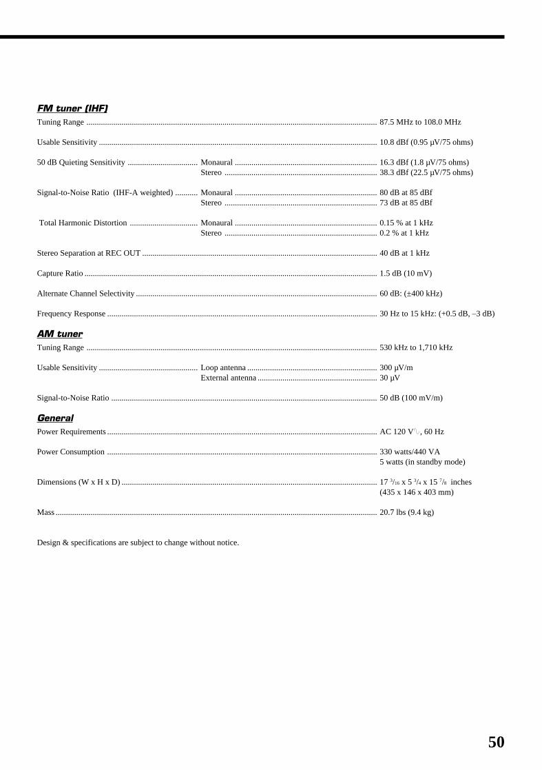
50
FM tuner (IHF)Tuning Range ............................................................................................................................................. 87.5 MHz to 108.0 MHz
Usable Sensitivity ....................................................................................................................................... 10.8 dBf (0.95 µV/75 ohms)
50 dB Quieting Sensitivity .................................. Monaural ..................................................................... 16.3 dBf (1.8 µV/75 ohms)Stereo .......................................................................... 38.3 dBf (22.5 µV/75 ohms)
Signal-to-Noise Ratio (IHF-A weighted) ........... Monaural ..................................................................... 80 dB at 85 dBfStereo .......................................................................... 73 dB at 85 dBf
Total Harmonic Distortion ................................. Monaural ..................................................................... 0.15 % at 1 kHzStereo .......................................................................... 0.2 % at 1 kHz
Stereo Separation at REC OUT .................................................................................................................. 40 dB at 1 kHz
Capture Ratio .............................................................................................................................................. 1.5 dB (10 mV)
Alternate Channel Selectivity ..................................................................................................................... 60 dB: (±400 kHz)
Frequency Response ................................................................................................................................... 30 Hz to 15 kHz: (+0.5 dB, –3 dB)
AM tunerTuning Range ............................................................................................................................................. 530 kHz to 1,710 kHz
Usable Sensitivity ................................................ Loop antenna ............................................................... 300 µV/mExternal antenna .......................................................... 30 µV
Signal-to-Noise Ratio ................................................................................................................................. 50 dB (100 mV/m)
GeneralPower Requirements ................................................................................................................................... AC 120 V, 60 Hz
Power Consumption ................................................................................................................................... 330 watts/440 VA5 watts (in standby mode)
Dimensions (W x H x D) ............................................................................................................................ 17 3/16 x 5 3/4 x 15 7/8 inches(435 x 146 x 403 mm)
Mass ............................................................................................................................................................ 20.7 lbs (9.4 kg)
Design & specifications are subject to change without notice.
RX-664VBK(J)_0119-001B_En.24-50 98.1.6, 11:30 AM50
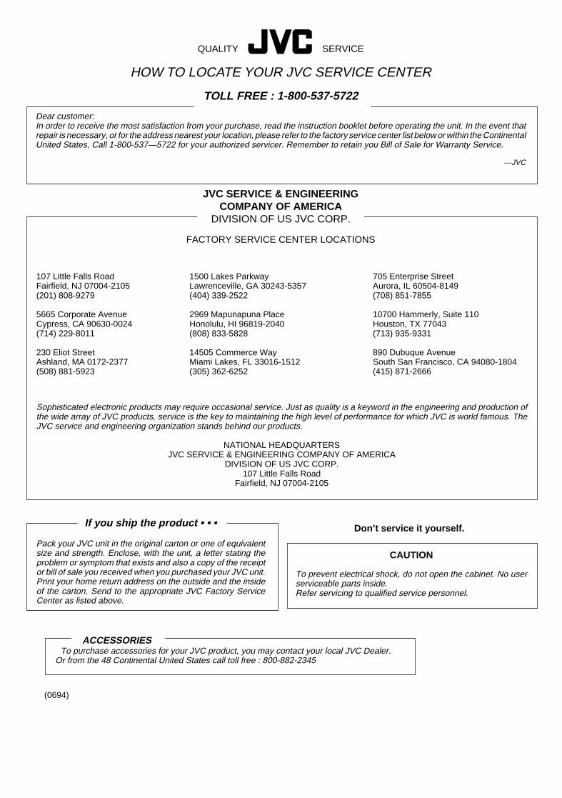
G-3
Sophisticated electronic products may require occasional service. Just as quality is a keyword in the engineering and production ofthe wide array of JVC products, service is the key to maintaining the high level of performance for which JVC is world famous. TheJVC service and engineering organization stands behind our products.
NATIONAL HEADQUARTERSJVC SERVICE & ENGINEERING COMPANY OF AMERICA
DIVISION OF US JVC CORP.107 Little Falls Road
Fairfield, NJ 07004-2105
If you ship the product • • •
Pack your JVC unit in the original carton or one of equivalentsize and strength. Enclose, with the unit, a letter stating theproblem or symptom that exists and also a copy of the receiptor bill of sale you received when you purchased your JVC unit.Print your home return address on the outside and the insideof the carton. Send to the appropriate JVC Factory ServiceCenter as listed above.
CAUTION
To prevent electrical shock, do not open the cabinet. No userserviceable parts inside.Refer servicing to qualified service personnel.
Don’t service it yourself.
ACCESSORIESTo purchase accessories for your JVC product, you may contact your local JVC Dealer.
Or from the 48 Continental United States call toll free : 800-882-2345
QUALITY SERVICE
HOW TO LOCATE YOUR JVC SERVICE CENTER
TOLL FREE : 1-800-537-5722
Dear customer:In order to receive the most satisfaction from your purchase, read the instruction booklet before operating the unit. In the event thatrepair is necessary, or for the address nearest your location, please refer to the factory service center list below or within the ContinentalUnited States, Call 1-800-537—5722 for your authorized servicer. Remember to retain you Bill of Sale for Warranty Service.
—JVC
JVC SERVICE & ENGINEERINGCOMPANY OF AMERICA
DIVISION OF US JVC CORP.
FACTORY SERVICE CENTER LOCATIONS
107 Little Falls RoadFairfield, NJ 07004-2105(201) 808-9279
5665 Corporate AvenueCypress, CA 90630-0024(714) 229-8011
230 Eliot StreetAshland, MA 0172-2377(508) 881-5923
705 Enterprise StreetAurora, IL 60504-8149(708) 851-7855
10700 Hammerly, Suite 110Houston, TX 77043(713) 935-9331
890 Dubuque AvenueSouth San Francisco, CA 94080-1804(415) 871-2666
1500 Lakes ParkwayLawrenceville, GA 30243-5357(404) 339-2522
2969 Mapunapuna PlaceHonolulu, HI 96819-2040(808) 833-5828
14505 Commerce WayMiami Lakes, FL 33016-1512(305) 362-6252
(0694)
RX-664VBK(J)_0119-001B.G-page 98.1.6, 11:21 AM3
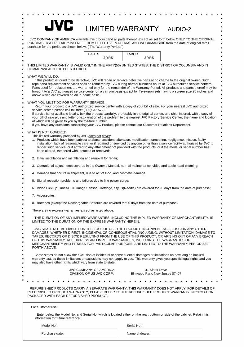
G-4
PARTS LABOR2 YRS 2 YRS
LIMITED WARRANTY AUDIO-2
JVC COMPANY OF AMERICA warrants this product and all parts thereof, except as set forth below ONLY TO THE ORIGINALPURCHASER AT RETAIL to be FREE FROM DEFECTIVE MATERIAL AND WORKMANSHIP from the date of original retailpurchase for the period as shown below. (“The Warranty Period.”)
THIS LIMITED WARRANTY IS VALID ONLY IN THE FIFTY(50) UNITED STATES, THE DISTRICT OF COLUMBIA AND INCOMMONWEALTH OF PUERTO RICO.
WHAT WE WILL DO:If this product is found to be defective, JVC will repair or replace defective parts at no charge to the original owner. Such
repair and replacement services shall be rendered by JVC during normal business hours at JVC authorized service centers.Parts used for replacement are warranted only for the remainder of the Warranty Period. All products and parts thereof may bebrought to a JVC authorized service center on a carry-in basis except for Television sets having a screen size 25 inches andabove which are covered on an in-home basis.
WHAT YOU MUST DO FOR WARRANTY SERVICE:Return your product to a JVC authorized service center with a copy of your bill of sale. For your nearest JVC authorized
service center, please call toll free: (800)537-5722.If service is not available locally, box the product carefully, preferably in the original carton, and ship, insured, with a copy ofyour bill of sale plus and letter of explanation of the problem to the nearest JVC Factory Service Center, the name and locationof which will be given to you by the toll-free number.If you have any questions concerning your JVC Product, please contact our Customer Relations Department.
WHAT IS NOT COVERED:This limited warranty provided by JVC does not cover:1. Products which have been subject to abuse, accident, alteration, modification, tampering, negligence, misuse, faulty
installation, lack of reasonable care, or if repaired or serviced by anyone other than a service facility authorized by JVC torender such service, or if affixed to any attachment not provided with the products, or if the model or serial number hasbeen altered, tampered with, defaced or removed;
2. Initial installation and installation and removal for repair;
3. Operational adjustments covered in the Owner’s Manual, normal maintenance, video and audio head cleaning;
4. Damage that occurs in shipment, due to act of God, and cosmetic damage;
5. Signal reception problems and failures due to line power surge;
6. Video Pick-up Tubes/CCD Image Sensor, Cartridge, Stylus(Needle) are covered for 90 days from the date of purchase;
7. Accessories;
8. Batteries (except the Rechargeable Batteries are covered for 90 days from the date of purchase);
There are no express warranties except as listed above.
THE DURATION OF ANY IMPLIED WARRANTIES, INCLUDING THE IMPLIED WARRANTY OF MARCHANTABILITY, ISLIMITED TO THE DURATION OF THE EXPRESS WARRANTY HEREIN.
JVC SHALL NOT BE LIABLE FOR THE LOSS OF USE THE PRODUCT, INCONVENIENCE, LOSS OR ANY OTHERDAMAGES, WHETHER DIRECT, INCIDENTAL OR CONSEQUENTIAL (INCLUDING, WITHOUT LIMITATION, DAMAGE TOTAPES, RECORDS OR DISCS) RESULTING FROM THE USE OF THIS PRODUCT, OR ARISING OUT OF ANY BREACHOF THIS WARRANTY. ALL EXPRESS AND IMPLIED WARRANTIES, INCLUDING THE WARRANTIES OFMERCHANTABILITY AND FITNESS FOR PARTICULAR PURPOSE, ARE LIMITED TO THE WARRANTY PERIOD SETFORTH ABOVE.
Some states do not allow the exclusion of incidental or consequential damages or limitations on how long an impliedwarranty last, so these limitations or exclusions may not apply to you. This warranty gives you specific legal rights and youmay also have other rights which vary from state to state.
JVC COMPANY OF AMERICA 41 Slater DriveDIVISION OF US JVC CORP. Elmwood Park, New Jersey 07407
REFURBISHED PRODUCTS CARRY A SEPARATE WARRANTY, THIS WARRANTY DOES NOT APPLY. FOR DETAILS OFREFURBISHED PRODUCT WARRANTY, PLEASE REFER TO THE REFURBISHED PRODUCT WARRANTY INFORMATIONPACKAGED WITH EACH REFURBISHED PRODUCT.
For customer use:
Enter below the Model No. and Serial No. which is located either on the rear, bottom or side of the cabinet. Retain thisinformation for future reference.
Model No.: Serial No.:
Purchase date: Name of dealer:
RX-664VBK(J)_0119-001B.G-page 98.1.6, 11:21 AM4

VICTOR COMPANY OF JAPAN, LIMITED
JVC 1297OFMMDWJEMEN
RX-664VBK(J)_0119-001B.Cover 98.1.6, 11:20 AM2