attacks on rfid-based electronic voting systems on rfid-based electronic voting ... the scheme...
TRANSCRIPT
Attacks on RFID-Based Electronic VotingSystems
Yossef Oren <[email protected]> and Avishai Wool <[email protected]>
Computer and Network Security Lab, School of Electrical Engineering, Tel-AvivUniversity, Ramat Aviv 69978, Israel
Abstract. Many secure systems, such as contactless credit cards andsecure entrance systems, are built with contactless smartcard RFID tech-nologies. In many cases these systems are claimed to be secure based onthe assumption that readers and tags need to be in close proximity (about5cm) in order to communicate. However, it is known that this proximityassumption is false: Relay attacks are a class of hardware-based attackswhich compromise the safety of such systems by dramatically extendingthe interrogation range of the contactless system. Interestingly, the pro-posed Israeli e-voting scheme is based on contactless smartcards. In thiswork we show how the proposed system can be completely compromisedusing low-cost relay attacks. Our attacks allow an adversary to read outall votes already cast into the ballot box, supress the votes of one or sev-eral voters, rewrite votes at will and even completely disqualify all votesin a single voting station. Our attacks are easy to mount, very difficultto detect, and compromise both the confidentiality and the integrity ofthe election system.
1 Introduction
1.1 A Typical Contactless RFID System
An RFID environment in general consists of a reader, a device connected to anexternal power source, communicating via a wireless medium with a multipleinexpensive tags. While there are several classes of such tags, this discussionspecifically deals with passively powered, magnetically coupled RFID tags(also referred to as tokens, prox-cards or contactless smartcards).Thesetags are used in new e-passports[7], credit cards[8], public transportation[16] andsecure entrance systems. Most passively powered, magnetically coupled RFIDtags conform to the ISO/IEC 14443[12] standard family. Passive tags contain nopower source and rely on the reader to provide them with operating power. Dueto the physical principles behind magnetic coupling, the reader is only capableof delivering power to the tag if the tag is near the reader’s antenna (StandardISO/IEC 14443 readers and tags are designed for a 5cm operating range). Thisproperty, which imposes a severe limit on the usable range of the system, issometimes considered erroneously as a security feature.
To provide for the case of multiple tags sharing the same air space (suchas communication with one out of several contactless smartcards which are all
located in the same wallet), the ISO/IEC 14443 standard specifies an anticolli-sion protocol which allows each tag to be interrogated in turn without corruptingthe communications with other tags. An in depth introduction to RFID can befound in [9].
1.2 The Theory Behind Relay Attacks
As stated in [9], most contactless smart card systems (and specifically the ISO14443 [12] family) operate on the physical principle of magnetic coupling. Thischoice of air interface, which is used both to provide power to the smartcardand to communicate with it wirelessly, is supposed to impose a very severelimit on the distance between the reader and the tag, as illustrated in figure 1.This leads to the (mistaken) implicit assumption that whenever a reader cancommunicate with a tag one can assume that the tag is physically very close tothe reader.
HF RFID T ag
HF RFID Read er 5 cmFig. 1. A simple magnetically-coupled RFID channel
As described in [14], relay attacks challenge this underlying assumption andallow a nearly unlimited distance between tag and reader. The attack achievesthis ability by placing a relay, consisting of custom-designed tag and readerhardware connected by a high-range communication link, between the victim’stag and reader.
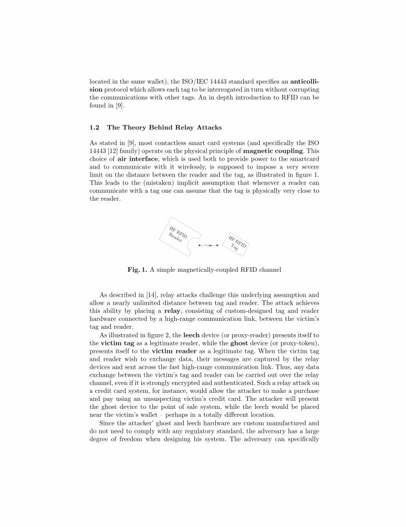
As illustrated in figure 2, the leech device (or proxy-reader) presents itself tothe victim tag as a legitimate reader, while the ghost device (or proxy-token),presents itself to the victim reader as a legitimate tag. When the victim tagand reader wish to exchange data, their messages are captured by the relaydevices and sent across the fast high-range communication link. Thus, any dataexchange between the victim’s tag and reader can be carried out over the relaychannel, even if it is strongly encrypted and authenticated. Such a relay attack ona credit card system, for instance, would allow the attacker to make a purchaseand pay using an unsuspecting victim’s credit card. The attacker will presentthe ghost device to the point of sale system, while the leech would be placednear the victim’s wallet – perhaps in a totally different location.
Since the attacker’ ghost and leech hardware are custom manufactured anddo not need to comply with any regulatory standard, the adversary has a largedegree of freedom when designing his system. The adversary can specifically
Victim Ta g
Victim Rea d er L
G
Fig. 2. An RFID channel under a relay attack. Device “L” is the leech, whiledevice “G” is the ghost.
design his ghost and leech so that they have an internal power supply, a differentform factor or (most importantly) a higher operating range.
Thus, there are three ways in which relay systems increase the distance be-tween the victim tag and victim reader:
1. Increasing the range between the victim tag and the leech (leech range)2. Increasing the range of the communications link between the leech and the
ghost (relay range)3. Increasing the range between the ghost and the victim reader (ghost
range)
1.3 Previous work on Relay Attacks
An excellent survey on the history and state of the art on relay attacks hasrecently been written by Hancke et al.[10]. As stated in the survey, the firstpublished discussion of a relay attack is arguably the “chess grandmaster” attack,which Conway writes about in his famous book “On Numbers and Games”[3].In the chess grandmaster attack, the adversary successfully plays simultaneouslyagainst two chess grandmasters by relaying their moves – even though he hasno knowledge or understanding of chess. In 1987 Desmedt et al. [4] wrote ofthe “mafia fraud” attack, the first discussion of a full-fledged relay attack usedto compromise a security protocol (specifically, the Fiat-Shamir authenticationprotocol).
In 2005 Kfir and Wool[14] first noted that applying a relay attack to a near-field contactless system will cause the security of such a system to “collapse”.They also used a detailed physical model of the physical layer to evaluate howthe ghost and leech distances can be significantly improved beyond the nominal10cm at a reasonable cost. They predicted that the leech range can be increasedto 40 to 50cm and that the ghost range can be made as large as 50m. In thatsame year Hancke[11] demonstrated a working relay attack on an NFC systemusing a high-speed radio link, using standard equipment for the ghost and leechradio interfaces and a low-cost radio transciever for the relay link. This setupprovided a relay range of about 50 meters. In 2006 Kirschenbum and Wool[15]
actually built a functioning leech element of the relay by demonstrating a low-cost RFID skimmer that provides a range of 25cm, thus validating the model-based prediction of [14]. The article also explained how the leech distance canbe improved even further while staying within a very low budget. A possibleway to protect against a relay attack would be through the use of Faraday cageshielding, or by employing a hardware based distance-bounding protocol whichstrongly proves physical proximity (see [6]), but even these protocols cannotreliably detect a short-range relay attack.
In 2007 Drimer et al.[6] applied a relay attack to a contact-based smartcard system implementing the high-security UK EMV payment system[8]. Oneoriginal aspect of this system was the design of the attacker’s ghost and leechdevices. Since the tag under attack was contact-based and designed to be usedin a point-of-sale setting, the authors took special care to make the ghost lookas much as possible like a standard EMV credit card. They achieved this feat bytaking a genuine card and connecting a long cable to the gold pads interfacingthe smardcard with the reader, with the other end of the cable wired to a hard-ware device implementing the relay functionality. This resulted in a card thatlooked authentic when viewed from the top side, but was actually connected toexternal hardware on the back side (see figure 2 in [6]). To make this attack un-detectable in the field, the relay device and connecting cable could presumablybe hidden up an attacker’s sleeve. The leech device (which is supposed to receivecommunications from the victim’s tag) was placed inside the box of a standardChip & PIN terminal, resulting in a device that looks perfectly genuine to thevictim.
2 The Israeli e-Voting Scheme
The scheme discussed in this report is based on the e-voting system currentlyundergoing a process of legal ratification and widespread pilot testing in Israel.Our information on the scheme comes from its official description in a patentapplication, currently under submission to the World International PropertyOrganization by the Government of Israel[19,5], and from discussions with YoramOren, one of the co-developers of the scheme[18].
The novelty of the system is that instead of using paper ballots, the votes inthe proposed system are cast on contactless smartcards. To cast their votes, thevoters use a computer terminal to write their choice into a contactless smartcard,and then physically deposit this smartcard into a ballot box. A more detaileddescription of the voting process follows.
2.1 Components of the Scheme
The components of a voting station are illustrated in figure 3. Each voting stationconsists of the following elements:
– A voting terminal (a portable computer with a contactless smartcardreader). The voter uses this terminal to cast his vote. The vote is recorded

Voting Booth
LocalElections
Committee
Ballot BoxVoting and Counting Terminal
Verification Terminal
B la nk B a llo ts
Ca st V o tes
Fig. 3. Physical layout of the proposed Israeli e-voting scheme. Illustrated fromleft to right are the voting booth, the cast ballot box and the local electioncommitee’s desk area.
twice: First, the individual vote is written onto the blank ballot (a contact-less RFID smart card). Second, the total vote count is immediately talliedand this total is written to a regular contact-based smart card plugged intothe voting terminal.
– A verification terminal (another portable computer with a contactlesssmartcard reader). This terminal is only capable of reading (and not writing)ballots. The voter can optionally place his written ballot on this terminal tomake sure his vote was correctly cast.
– A set of blank ballots, taking the form of secure contactless smart cardswhich are cryptographically paired with this specific instance of voting andverification terminals (see subsection 2.3).
– A voting booth, formed by folding a cardboard divider, that hides thevoting and verification terminal from the elections committee and allows thevoter to vote in privacy.
– A ballot box, where cast ballots (written contactless smartcards) are phys-ically collected. The ballot boxes are typically made out of cardboard sheets,which are delivered flat and folded into shape on election day.
– The local elections committee, which typically consists of three mutuallydistrustful (and technologically inexperienced) members nominated by theparties participating in the elections. These local commitees in turn reportto a central elections committee which oversees the election process.
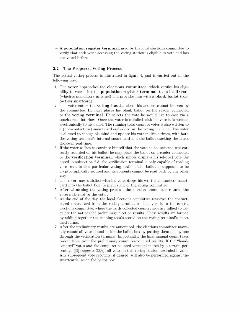
– A population register terminal, used by the local elections committee toverify that each voter accessing the voting station is eligible to vote and hasnot voted before.
2.2 The Proposed Voting Process
The actual voting process is illustrated in figure 4, and is carried out in thefollowing way:1. The voter approaches the elections committee, which verifies his eligi-
bility to vote using the population register terminal, takes his ID card(which is mandatory in Israel) and provides him with a blank ballot (con-tactless smartcard).
2. The voter enters the voting booth, where his actions cannot be seen bythe committee. He next places his blank ballot on the reader connectedto the voting terminal. He selects the vote he would like to cast via atouchscreen interface. Once the voter is satisfied with his vote it is writtenelectronically to his ballot. The running total count of votes is also written toa (non-contactless) smart card embedded in the voting machine. The voteris allowed to change his mind and update his vote multiple times, with boththe voting terminal’s internal smart card and the ballot tracking the latestchoice in real time.
3. If the voter wishes to convince himself that the vote he has selected was cor-rectly recorded on his ballot, he may place the ballot on a reader connectedto the verification terminal, which simply displays his selected vote. Asnoted in subsection 2.3, the verification terminal is only capable of readingvotes cast in this particular voting station. The ballot is supposed to becryptographically secured and its contents cannot be read back by any otherway.
4. The voter, now satisfied with his vote, drops his written contactless smart-card into the ballot box, in plain sight of the voting committee.
5. After witnessing the voting process, the elections committee returns thevoter’s ID card to the voter.
6. At the end of the day, the local elections committee retrieves the contact-based smart card from the voting terminal and delivers it to the centralelections committee, where the cards collected countrywide are tallied to cal-culate the nationwide preliminary election results. These results are formedby adding together the running totals stored on the voting terminal’s smartcard forms.
7. After the preliminary results are announced, the elections committee manu-ally counts all votes found inside the ballot box by passing them one by onethrough the verification terminal. Importantly, the final manual count takesprecendence over the preliminary computer-counted results. If the “hand-counted” votes and the computer-counted votes mismatch by a certain per-centage ([5] suggests 30%), all votes in this voting station are ruled invalid.Any subsequent vote recounts, if desired, will also be performed against thesmartcards inside the ballot box.
Voter
Verify and Deposit ID, Acquire Blank Ballot
Cast Vote –Vote is
Automatically Counted
(optional) Verify Vote was Cast Correctly
Deposit Vote in Ballot Box
Retrieve ID
�
�
�
�
�
Voting Booth
LocalElections Committee
Ballot BoxVoting and Counting Terminal
Verification Terminal
B la nk B a llo ts
Ca st Vo tes
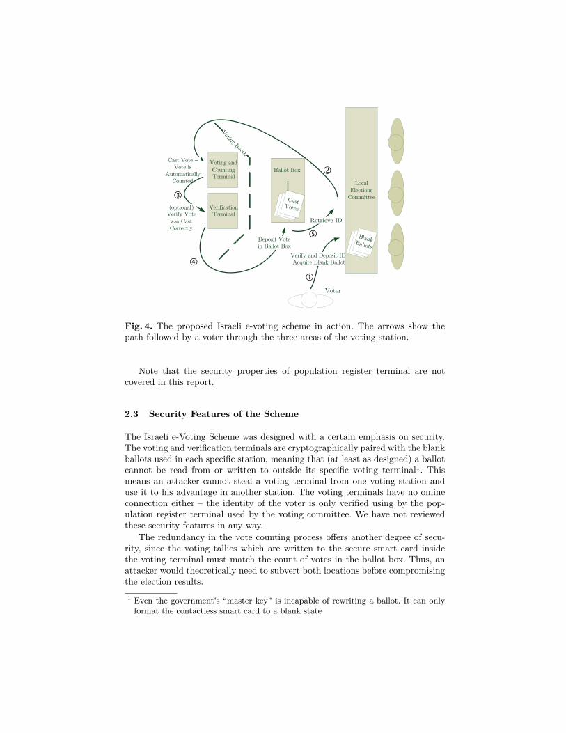
Fig. 4. The proposed Israeli e-voting scheme in action. The arrows show thepath followed by a voter through the three areas of the voting station.
Note that the security properties of population register terminal are notcovered in this report.
2.3 Security Features of the Scheme
The Israeli e-Voting Scheme was designed with a certain emphasis on security.The voting and verification terminals are cryptographically paired with the blankballots used in each specific station, meaning that (at least as designed) a ballotcannot be read from or written to outside its specific voting terminal1. Thismeans an attacker cannot steal a voting terminal from one voting station anduse it to his advantage in another station. The voting terminals have no onlineconnection either – the identity of the voter is only verified using by the pop-ulation register terminal used by the voting committee. We have not reviewedthese security features in any way.
The redundancy in the vote counting process offers another degree of secu-rity, since the voting tallies which are written to the secure smart card insidethe voting terminal must match the count of votes in the ballot box. Thus, anattacker would theoretically need to subvert both locations before compromisingthe election results.1 Even the government’s “master key” is incapable of rewriting a ballot. It can onlyformat the contactless smart card to a blank state
The designers of the Israeli e-voting scheme chose near-field contactless read-ers instead of traditional smartcards for non-security-related reasons. First andmost important is the issue of cost and reliability – since a contactless smartcardreader has no mechanical interface and no moving parts (in contrast to a tradi-tional smart card or magnetic-stripe reader), it can survive many more repeateduses with a reduced opportunity for damage or deliberate vandalism. In addi-tion, as observed in [10], contactless smartcards are easier to use than magneticstripe cards or traditional smart cards since they work regardless of the way thecard is oriented with respect to the reader. Cost saving is also reportedly thereason why the system has absolutely no paper trail – the designers wished tosave on the cost of maintaining and supplying paper to thousands of printers onelection day.
Note that this system has been criticized by many (cf. [20,21]), specificallyfor its lack of a paper trail, but also for its cost and possible discriminatorynature against the technologically challenged such as the poor, uneducated orelderly voters. In this work our goal is to provide a purely technical critique thatis based on the suspectibility of the system to physical layer attacks and to relayattacks in particular.
3 Relay Attacks on the e-Voting Scheme
As mentioned before, the fact that legitimate contactless smartcards have alimited read range should not be considered a security feature. Specifically, thefact that a certain tag is communicating with a certain reader does not implywith any certainty that the tag and reader are in proximity. In our attacks, weuse this flaw to create a communications link from the voting and verificationterminals inside the voting booth to the RFID-based ballots inside the ballotbox that carry votes which were already cast.
One specific aspect of the voting process makes relay attacks even moreeffective in this context. As stated in the previous subsection, in conventionalrelay attacks the attacker’s tag (or ghost device) is generally used in a legitimatepoint-of-sale or conditional entry scenario, and as such must look very similar toan authentic tag to avoid suspicion. Fortunately for our attacker, this limitationon the physical form of the ghost does not exist when attacking the Israeli votingsystem – when performing relay attacks on the election terminals, the attackeris hidden inside the booth and is promised a high degree of privacy by thevery nature of the voting process itself. This means that the ghost end of theattacker’s relay setup can take any arbitrary form. The attacker may even use histime in the voting booth to replace the entire ensemble of voting and verificationterminals with hacked machines running his own code (as the authors of [6] didwhen attacking EMV systems). The reader end (or leech device) can likewise begiven an arbitrary shape, if we make the reasonable assumption that the votercan approach the voting commitee carrying a backpack or bag and ask themto mind his bag while he votes, or even consider the possibility that one of thethree members of the elections committee is collaborating with the adversary.
The following subsections outline several relay attack scenarios that are pos-sible against the proposed Israeli voting system. This is not an exhaustive list:there may be other scenarios which we did not consider.
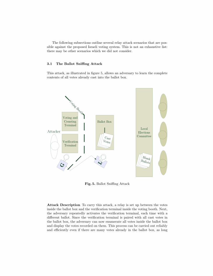
3.1 The Ballot Sniffing Attack
This attack, as illustrated in figure 5, allows an adversary to learn the completecontents of all votes already cast into the ballot box.
LG
Voting Booth
LocalElections
Committee
Ballot BoxVoting and Counting Terminal
Verification Terminal
B la nk B a llo ts
Ca st Vo tes
Attacker
Fig. 5. Ballot Sniffing Attack
Attack Description To carry this attack, a relay is set up between the votesinside the ballot box and the verification terminal inside the voting booth. Next,the adversary repeatedly activates the verification terminal, each time with adifferent ballot. Since the verification terminal is paired with all cast votes inthe ballot box, the adversary can now enumerate all votes inside the ballot boxand display the votes recorded on them. This process can be carried out reliablyand efficiently even if there are many votes already in the ballot box, as long
Voting Booth
LocalElections
Committee
Ballot BoxVoting and Counting Terminal
Verification Terminal
B la nk B a llo ts
Ca st Vo tes
Attacker
Dissident (s)Sing le Dissident B a llo t
Enable/Disable Relays
LG
G
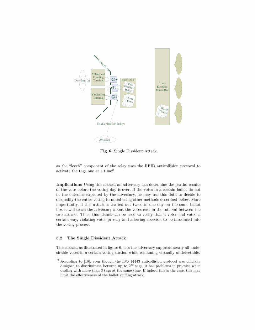
Fig. 6. Single Dissident Attack
as the “leech” component of the relay uses the RFID anticollision protocol toactivate the tags one at a time2.
Implications Using this attack, an adversary can determine the partial resultsof the vote before the voting day is over. If the votes in a certain ballot do notfit the outcome expected by the adversary, he may use this data to decide todisqualify the entire voting terminal using other methods described below. Moreimportantly, if this attack is carried out twice in one day on the same ballotbox it will teach the adversary about the votes cast in the interval between thetwo attacks. Thus, this attack can be used to verify that a voter had voted acertain way, violating voter privacy and allowing coercion to be inroduced intothe voting process.
3.2 The Single Dissident Attack
This attack, as illustrated in figure 6, lets the adversary suppress nearly all unde-sirable votes in a certain voting station while remaining virtually undetectable.2 According to [18], even though the ISO 14443 anticollision protocol was officiallydesigned to discriminate between up to 232 tags, it has problems in practice whendealing with more than 3 tags at the same time. If indeed this is the case, this maylimit the effectiveness of the ballot sniffing attack.
Attack Description To carry out this attack, the adversary needs to be presentnear the voting terminal while another voter is voting (for example, the adver-sary may volunteer to serve on this specific election committee or simply standoutside). As a prerequisite to this attack, the adversary sets up a relay betweenthe voting and verification terminals and a single previously cast vote locatedinside the ballot box, hereby called the “single dissident vote”. This relay canbe turned on and off as desired by the adversary. The adversary then selects acertain group of voters whose voice he wishes to suppress3. In general, the relayswill operate only when one of these “dissidents” is inside the voting booth. Asstated previously, an attacker can easily obtain such fine-grained control over thevoting and verification systems if he replaces both terminals inside the votingbooth with similar-looking computers running his own code (see [6]).
When the relay attack is active, all of the dissenting voter’s actions (voting,verifying, etc.) are not performed against the blank ballot he is holding, butrather shunted to the single dissident vote already in the ballot box. Since thissingle ballot is properly authenticated, both the voting and the verification ter-minals happily register the vote and display its correct value. Thus, the voterhas no idea that the attack is taking place, but his personal ballot always staysblank. After the voter exits the booth, he casts his blank vote into the ballotbox and his vote is effectively disqualified and ignored.
Implications If the adversary manages to correctly guess the disposition of thevoter, this attack makes sure the ballot box contains no more than one dissentingvote for each undesirable party. Because of the relay attack all other dissentingvoters will register as blank, or invalid, votes, and have no effect on the outcomeof the elections. Since the votes inside the ballot box correlate directly with thevalues written to the smart card inside the voting terminal, the recount at theend of the voting day will find no discrepancy between the two. However, thereis only one vote left to represent any amount of dissenting voters.
While this attack seems at first difficult to set up and carry out, it has theadvantage of being virtually undetectable. If one of the dissenting voters getssuspicious and tries to find traces of this attack, even manual examination ofthe per-box vote counts will not reveal the subterfuge in this case, since eachvoter can be certain only of his personal vote, and at least one dissenting votehas been registered in this ballot. Thus, each dissident will be forced to concludethat his accomplices had a change of heart at the ballot, and that he is indeedthe only one to have placed a dissenting vote in this specific ballot box.
If the attacker is somewhat uncertain of his ability to guess how a voter willbehave inside the booth, he can use not one but several dissident votes and mapthe dissenting voters at random into one of this small set whenever one of thementers the booth. Since only a single vote for each party needs to be registered at3 The attack builds on the assumption that the the adversary can guess the voteof a some voters based on their external characteristics or some other auxiliaryinformation. This is very reasonable in general, and even more so in Israel given thehighly heterogenous nature of the Israeli voting body.

the voting terminal for the attack to be undetectable, the probability of failurecan be significantly reduced by choosing an appropriate size for this group.
Note that according to [18] the voting terminal can somehow keep track ofwhich ballots it wrote to, and refuse to connect to previously written tags as soonas it encounters a new tag. We cannot comment on this mechanism since thedocumentation given in [19] does not specify exacly what identifier is recordedand how the mechanism should work. Indeed, it seems difficult to provide thisfunctionality without exposing the system to voter privacy violation or to denialof service attacks. Nontheless, such a mechanism may limit the effectiveness ofthe single dissident attack.
3.3 The Ballot Stuffing Attack
This attack, as illustrated in figure 6, gives an adversary complete control overpreviously cast votes, using a relay attack to rewrite them to the candidate ofhis choice.
Attacker
Voting Booth
LocalElections
Committee
Ballot BoxVoting and Counting Terminal
Verification Terminal
B la nk B a llo ts
Ca st Vo tes
L
G
Fig. 7. Ballot Stuffing Attack
Attack Description To carry out this attack, a relay is set up between theballot box and the voting terminal. Next, the adversary enters the voting booth
and repeatedly votes for the candidate of his choice, each time with a differentballot selected from the ballots already inside the ballot box. Since the votingterminal is paired with the previously cast votes, it has no reason to prevent thevotes from being modified. Since the voting terminal itself is used to performthe attack, it constantly updates its running vote counts and thus remains inperfect sync with the cast votes instead the ballot box4. This means that thisattack causes no discrepancy which can be detected during a recount. The RFIDanticollision protocol allows this process to be carried out reliably and efficientlyeven if there are many votes already in the ballot box. The ability to rewriteballots multiple times is a confirmed feature[18] of the system.
Implications This attack is the most conspicouous of all attacks presentedhere, but it is the most powerful, since it allows the entire set of ballots to berewritten arbitrarily. As noted in the previous subsection, the only sort of fraudthat is detectable by mutually distrustful voters would be the case when a partythe voter had personally voted for ends up with zero votes in this ballot. If theadversary had previously applied the ballot sniffing attack to read all votes inthe ballot, he can avoid this form of detection by registering one vote for eachparty originally represented in the ballot under attack and giving all other votesto his candidate of choice. The lack of paper trail means that this attack isundetectable and unprovable, even though it has the potential to arouse votersuspicion if used crudely. Note that the countermeasures sketched in the twoprevious subsections affect this attack as well.
4 Non-Relay Attacks
The relay attacks described in the previous section require some sophisticationand a minor budget from the attacker. In addition to these attacks, the RFIDtechnology used in the proposed voting system is also susceptible to simplerhardware-based attacks.
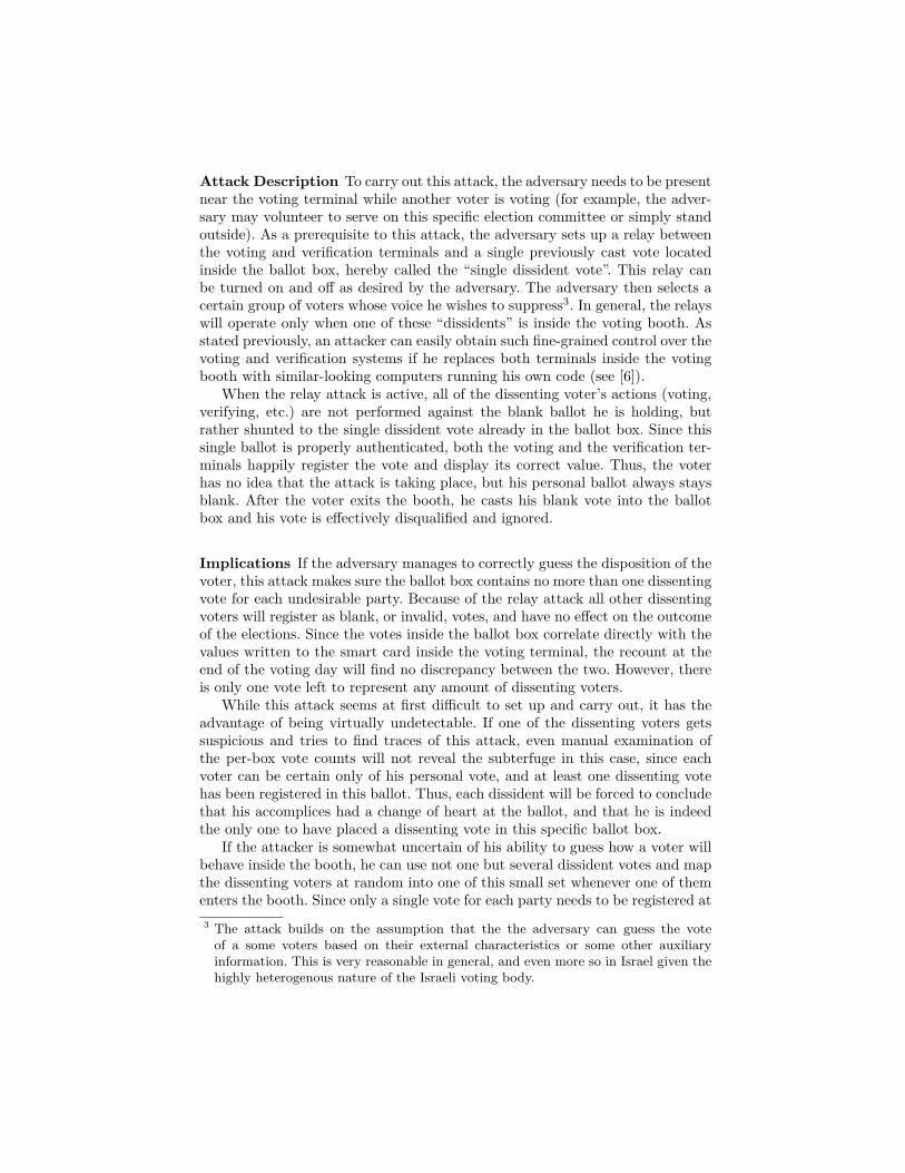
4.1 The Zapper Attack
This relatively low-tech attack, illustrated in figure 8, can quickly and easilydisqualify a certain ballot box, allowing an adversary coarse-grained control overthe results of the election.
Attack Description This attack assumes that the adversary had decided(based on apriori demographic knowledge or on information gained by the bal-lot sniffing attack described in subsection 3.1) that the votes cast by the entire4 We assume that the voting terminal handles multiple votes using the same card bysubtracting one vote from the old choice and adding one vote to the new choice, andthat there is no “finalizing” step which locks the card from subsequent edits. Thisinterpretation was validated by [18].
Zap!Attacker
Voting Booth
LocalElections
Committee
Ballot BoxVoting and Counting Terminal
Verification Terminal
B la nk B a llo ts
Ca st V o tes
Fig. 8. Zapper Attack

population of a single ballot box are not to his liking. The adversary can makeuse of a low-cost “RFID Zapper” device[17], consisting of a pulsed power source(most conveniently, the flash circuit from a disposable camera) connected to aproperly shaped reader antenna. When the pulsed power source (e.g. flash cam-era) is activated, a powerful electromagnetic pulse flows through the antennaand “zaps” any RFID tag close enough to couple magnetically with this antennawith a powerful surge of current which overwhelms its input circuits and gener-ally renders it unusable. A live video demonstration of such a device being usedto disable an ISO/IEC 14443 tag can be found in [2, starting at 19:00]. Once30% of the tags inside the ballot box are “zapped”, this will cause a discrepancybetween the count of ballots held by the smartcard located inside the votingterminal and those counted manually by the elections committee, causing theentire ballot to be legally disqualified.
We were told [18] that the high-end Java cards selected for the Israeli electionscontain circuitry to protect them against static electricity shocks, which mayoffer some protection against zapping. It is unclear how well these defenses workagainst a high-power burst of energy produced by a dedicated zapper device, asopposed to a high-voltage DC electric shock.
Implications This attack allows anybody with access to a ballot box to quicklyand undetectably disqualify its contents and remove it from the election process.The ballot box can be zapped during the election process or later, while the bal-lots are kept pending the manual recount. This attack is so easy and inexpensiveto carry out that it may be even done for reasons of malice or protest, and notjust for changing the election results.
4.2 Jamming, Blocking and Selective Denial of Service
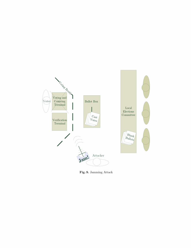
The jamming attacks illustrated in figure 9 can disrupt the operation of theRFID reader at a distance. They can be turned on and off on demand.
Attack Description While the physical interface used by the tag is basedon magnetic coupling, most RFID readers actually use a standard radio de-coding technique called single side-band (SSB) demodulation to decode the tagresponses. As noted in [14], this property allows the ghost component of a relayto work at distances of up to 50 meters, but it also means that the reader’sstandard operation can be disrupted by SSB modulated signals sent to it froma distant radio antenna. To carry out this attack the attacker uses a directedantenna to broadcast a random SSB-modulated bit pattern toward the readerat the tag’s upper side-band frequency of 14.4075 MHz. The reader connectedto the voting terminal will not be able to distinguish between this disruptivesignal and the tag’s response, rendering the reader inoperative and creating aneffective denial of service attack.
A similar attack can be performed by hiding a “Blocker Tag”[13] somewherewithin the voting booth (for example, between the voting terminal and the table
Voting Booth
LocalElections
Committee
Ballot BoxVoting and Counting Terminal
Verification Terminal
B la nk B a llo ts
Ca st Vo tes
Ja m!
Voter
Attacker
Fig. 9. Jamming Attack
on which it is set). This tag is a special hardware device which conforms onlypartially to the RFID specification – specifically, it ignores the tag anti-collisionprotocol under certain conditions, disrupting tag and reader communications.The blocker tag presented in [13] prevents RFID readers from communicatingwith tags whose ID matches certain criteria while allowing all other commu-nications. The design can be modified to support a high-range remote controlinterface allowing blocking to be turned on and off on demand, creating anotherhard to detect denial of service system.
Implications The jamming attack is a selective denial of service attack,since it is easy to apply selectively only to a certain subset of voters at thediscretion of the attacker. This attack is also unique in its very high operatingrange. It cannot be prevented unless electromagnetic shielding is applied to thewalls, doors and windows of every voting station (and not just the ballot boxitself).
4.3 Faulty Implementation Attacks
As stated in subsection 2.3, the Israeli voting scheme has certain security prop-erties built in by design, most significantly the cryptographic pairing of blankballots and voting terminals. This pairing means that a compromised termi-nal stolen from one voting station cannot be used to attack another station.Throughout this article we assumed that this security feature was properly im-plemented. A proper implementation would mean that both terminals and blankballot authenticate each other via public key, they execute a properly randomizedkey exchange protocol resulting in the generation of a random session key, and allmessages sent under this session key are properly randomized, padded, encryptedand MACed to prevent replay or message modification attacks. However, imple-mentation flaws in any part of the cryptographic pairing process immediatelymake the system even more vulnerable. Here are some examples:
1. If the authentication process consists of a highly secure and authenticated“unlocking” phase followed by a less secured exchange of commands withthe “unlocked” tag, the attacker can wait until a tag is legitimately unlockedand then take control of the conversation and send his own commands tothe unlocked tag, allowing him to influence the voting results or disqualifyan entire voting terminal. This mode of operation is actually common inseveral low-security RFID protocols, such as the EPC Gen-2 memory writecommand[1].
2. If encryption is not randomized, then there would only be as many possibleencrypted messages as the number of parties in the elections – well under100 values in Israel.
3. If the messages are not padded to a fixed length and the plaintext includes thefull name of the selected party, then the encrypted message length divulgesinformation about the encrypted content.
5 Countermeasures
This section lists several countermeasures which can be applied to increase thesecurity of the proposed system. Even with all of these countermeasures applied,the system as proposed seems “too broken” to be used in a high-stakes demo-cratic process. However, it would make good sense to apply them if a futurevariant of the scheme is used for a less important purpose than a democraticelection.
5.1 Physical Layer Security
The most crucial protection mechanism against relay attacks is that the votingstation and its environment should be protected from all forms of electromagneticradiation. Most importantly, the ballot box should be made into a Faraday cageby constructing it from a sufficiently thick sheet of conducting material such asaluminum. Ferric materials such as iron are probably less suitable since they maynot block magnetic coupling between reader and tag. Electromagnetic shieldingshould also be applied to the walls, windows and doors of the voting station itself,to prevent jamming and selective denial of service attacks from being carried outfrom a distance. A handy indicator of proper shielding would be the total lackof cellphone reception inside the voting station. Furthermore, when outside theballot box, the individual ballots (used or not) should be carried inside envelopesmade of conducting metal.
The ballot box should also be kept away from any object large enough tohide a leech device. To be on the safe side, no object should be allowed to comewithin a 1m radius of the ballot box. In particular, the ballot box should not beon or near the committee table. One open question is how to allow an untrustedvoter to approach the ballot box and deposit his vote.
5.2 Audio Feedback and Cooldown
The voting and verification terminals should be programmed to emit a loudbeep each time they read or write a tag. In addition, the terminals should havea “cooldown” period of at least 30 seconds between each use, or at least beforeswitching from one tag to another. Any attempts at wholesale vote sniffing orrewriting will now take a long time and result in many conspicuous beeps, afact that should arouse the suspicion of the voting commitee. Note that thesecountermeasures have no effect on the single dissident attack (which registers asingle vote per voter), nor do they prevent a single voter from modifying a smallbut constant amount of votes.
5.3 Single-Write Ballots
The voting station should include some sort of irreversible “commitment” orballot cancellation process (similar to the one performed on paper stamps) which
will finalize the vote so the RFID smartcard can be read from but not written toagain. In the best case this can be accompanied by a visible mark on the ballotitself. The single dissident attack described in subsection 3.2 will still work in thiscase if the adversary belongs to the elections committee, since he can keep one un-committed smart card especially for this purpose and perform the relay attacksagainst this dedicated card. Note that this countermeasure makes the e-votingscheme less cost effective, since it makes the ballots one-use-only and precludesthem from being used over multiple elections. According to [18], the proposedimplementation is supposed to include an (as yet undocumented) mechanismalong these lines.
5.4 Strong Probabilistic Encryption
To protect against implementation attacks, the data exchanged between theballot and the reader should use well-established security best practices. Allconversations between the tag and the reader should be authenticated by theprivate keys of both tag and reader and encrypted by a per-session key. The vot-ing data, which probably consists of a very short payload indicating the selectedparty, should be padded with random bytes to a constant length and contain asequence number (to prevent replay attacks on voters who change their minds).
6 Conclusion
In this work we have shown how any party with moderate technical expertiseand a fairly small budget can completely compromise the proposed Israeli e-voting system. Our attacks are aided by the fact that the voter’s actions inthe voting booth are unmonitored, by the design choice of making the tagsrewritable, and by the additional fact that the local elections commitee aretypically technologically inexperienced.
Despite the threat of relay attacks, contactless RFID smardcards are in usein sensitive applications such as credit cards, e-passports and secure entrancesystems, so one may think that they are good enough for e-voting as well. Un-fortunately, in these other applications there are always additional security mech-anisms: audit trails, credit card statements, insurance, security cameras, humanguards, store clerks or border officials. In a voting application, voter privacy bydesign eliminates the possibility for all of these additional safeguards. Unlessthe attacker is caught “red handed” during the attack, a relay attack on anelection may well be a perfect crime.
The designers of the voting system most probably chose contactless technol-ogy for cost and reliability reasons. However, this choice led to a devastatingside effect in the form of the relay attack. In its current form, the proposedsystem cannot guarantee the privacy of voters, and it cannot promise that castvotes were not manipulated after the fact. We have offered a few suggestionsthat, if properly implemented, can mitigate some of the attacks. Nevertheless,

viewed together with the substantial non-technical flaws with the system (as dis-cussed in subsection 2.3), we believe the proposed system is strictly inferior to,and completely unacceptable as a replacement for, the plain-paper ballot systemcurrently used in Israel.
References1. Epcglobal inc., EPC radio-frequency identity protocols class-1 generation-2 UHF
RFID protocol for communications at 860 MHz – 960 MHz, version 1.0.9. On-line, September 2005. http://www.epcglobalinc.org/standards_technology/EPCglobal2UHFRFIDProtocolV109122005.pdf.
2. CCC-TV lightning talks day 1. Online, 2005. http://media.ccc.de/browse/congress/2005/22C3-911-en-lightning_talk_day_1.html.
3. J. H. Conway. On Numbers and Games. Academic Press, 1976.4. Y. Desmedt, C. Goutier, and S. Bengio. Special uses and abuses of the Fiat-Shamir
passport protocol. In CRYPTO, pages 21–39, 1987.5. B. Dolev. Laying the groundwork for electronic elections in Israel (in Hebrew).
Invited Talk, CPIIS IDC/TAU Workshop on Electronic Voting, May 2009. http://www.cs.tau.ac.il/voting/.
6. S. Drimer and S. J. Murdoch. Keep your enemies close: distance bounding againstsmartcard relay attacks. In Proceedings of 16th USENIX Security Symposium,pages 1–16, Boston, MA, 2007. USENIX Association.
7. European commission decision c(2006) 2909: Technical specifications on the stan-dards for security features and biometrics in passports and travel documents. On-line, June 2006. http://ec.europa.eu/justice_home/doc_centre/freetravel/documents/doc_freetravel_documents_en.htm.
8. EMVCo contactless communication protocol specification v2.0.1. Online, July2009. http://www.emvco.com/specifications.aspx?id=21.
9. K. Finkenzeller. RFID Handbook : Fundamentals and Applications in ContactlessSmart Cards and Identification. John Wiley & Sons, 2003.
10. G. Hancke, K. Mayes, and K. Markantonakis. Confidence in smart token proximity:Relay attacks revisited. Computers & Security, In Press, Accepted Manuscript:–,2009.
11. G. P. Hancke. Practical attacks on proximity identification systems (short paper).In SP ’06: Proceedings of the 2006 IEEE Symposium on Security and Privacy,pages 328–333, Oakland, CA, 2006. IEEE Computer Society.
12. International Organization for Standardization, Geneva. ISO/IEC 14443-2 Iden-tification cards – Contactless integrated circuit(s) cards – Proximity cards – Part2: Radio frequency power and signal interface, 2001.
13. A. Juels, R. L. Rivest, and M. Szydlo. The blocker tag: selective blocking of rfidtags for consumer privacy. In CCS ’03: Proceedings of the 10th ACM conference onComputer and communications security, pages 103–111. ACM Press, 2003. http://doi.acm.org/10.1145/948109.948126.
14. Z. Kfir and A. Wool. Picking virtual pockets using relay attacks on contactlesssmartcards. In International Conference on Security and Privacy for EmergingAreas in Communications Networks, pages 47–58, Los Alamitos, CA, USA, 2005.IEEE Computer Society.
15. I. Kirschenbaum and A. Wool. How to build a low-cost, extended-range RFIDskimmer. In Proceedings of the 15th USENIX Security Symposium, Vancouver,B.C., Canada, 2006. USENIX Association.

16. Easing travel in london’s congested public transport network. Online, June 2003.http://mifare.net/showcases/london.asp.
17. T. "Minime" and C. "Mahajivana". RFID zapper. 22nd Chaos Communica-tion Congress, December 2005. https://events.ccc.de/congress/2005/wiki/RFID-Zapper(EN).
18. Y. A. Oren. Personal communication.19. Y. A. Oren, P. Rosenblum, O. Margoninsky, I. Yom-Tov, and B. Dolev. Israeli
patent application 192,999: Electronic voting system. Draft available online, 2008.http://idisk.mac.com/boaz.dolev-Public?view=web.
20. A. Rosen and A. Ta-Shma. Electronic voting in Israel. Online. http://sites.google.com/site/evotingisrael/.
21. R. Weil. Big brother and the slippery slope: On the challenges of e-voting (inHebrew). Invited Talk, CPIIS IDC/TAU Workshop on Electronic Voting, May2009. http://www.cs.tau.ac.il/voting/.