attachment 5 - work plan groundwater ... 5 - work plan groundwater monitoring wells installation...
TRANSCRIPT
ATTACHMENT 5 - WORK PLAN
GROUNDWATER MONITORING WELLS INSTALLATION PROJECT SYLMAR GROUNDWATER BASIN
Prepared For: California Department of Water Resources (DWR)
Local Groundwater Assistance (LGA) Grant Program
By:
Los Angeles Department of Water and Power (LADWP) 111 N. Hope Street, Room 1463
Los Angeles, CA 90064
July 12, 2012

TABLE OF CONTENTS
1. INTRODUCTION.................................................................................................. 1
2. BACKGROUND ................................................................................................... 1
2.1 Site Description ..................................................................................................... 1
2.2 Site History ............................................................................................................ 1
3. PROJECT INFORMATION .................................................................................. 2
3.1 General Project Description .................................................................................. 2
3.2 Goals and Objectives ............................................................................................ 2
4. PROJECT SCOPE OF WORK............................................................................. 3
4.1 Task 1: Bid, Award, Permitting & Planning, July - December 2012....................... 3
4.2 Task 2: First Well Construction (MI-MW-01), Development and Sampling, January – April 2013 ............................................................................................. 5
4.3 Task 3: Second Well (MI-MW-02) Construction, Development and Sampling, April – August 2013 ............................................................................................... 7
5. PROJECT MANAGEMENT.................................................................................. 7
6. PROJECT SCHEDULE........................................................................................ 8
LIST OF FIGURES Figure 1: Sylmar Groundwater Basin Location Map
Figure 2: Mission Wellfield Location Map
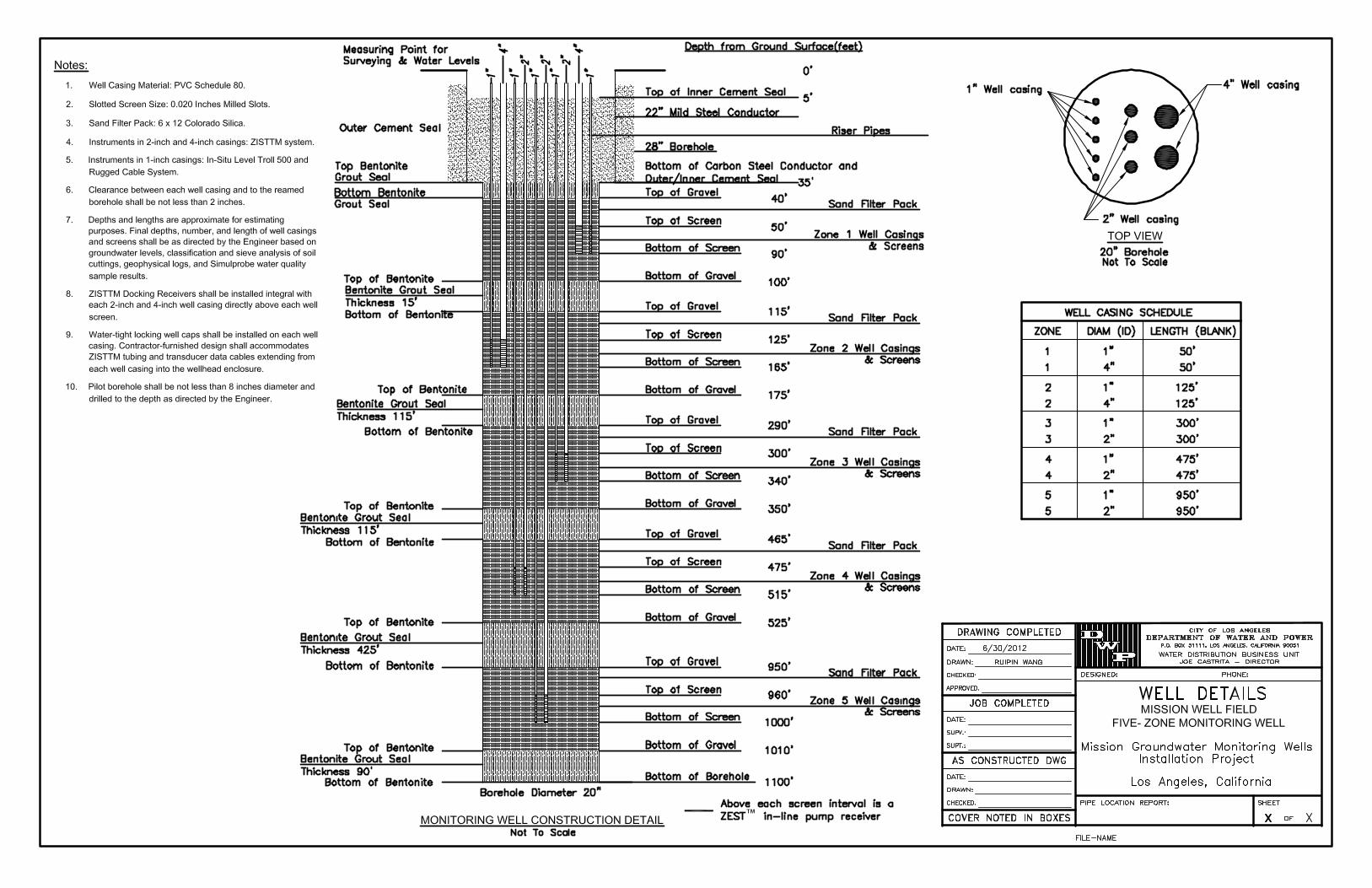
Figure 3: General Well Design Detail 1
Figure 4: General Well Design Detail 2
LIST OF APPENDICES Appendix A: Specification 7315, Part F – Detailed Specifications, Division F2 – Site
Construction, Section F02523 – Monitoring Wells in Sylmar Basin
Appendix B: Example Sampling and Analysis Plan (SAP) (without attachments)

Attachment 5 - LGA Application Work Plan Groundwater Monitoring Wells Installation Project – Sylmar Basin Los Angeles Department of Water and Power
7/12/2012 Page 1
1. INTRODUCTION
This work plan was prepared by the Los Angeles Department of Water and Power (LADWP) for the Groundwater Monitoring Wells Installation Project, Sylmar Groundwater Basin (Project), to support a grant application for funding from the California Department of Water Resources (DWR) Local Groundwater Assistance (LGA) Program. It was prepared in accordance with the guidance document provided by the DWR titled “Guidelines and Proposal Solicitation Package, Local Groundwater Assistance Program” and dated May 2012 (Guidelines).
2. BACKGROUND
The LADWP is seeking funding for the portion of its Groundwater Monitoring Wells Installation Project that will be conducted in the Sylmar Groundwater Basin. The Sylmar Basin is adjudicated under a 1979 judgment agreement (California Superior Court Judgment 650079) and related stipulations that encompass pumping rights in all four groundwater basins (San Fernando, Sylmar, Verdugo, and Eagle Rock) in the Upper Los Angeles River Area (ULARA) watershed.
2.1 Site Description
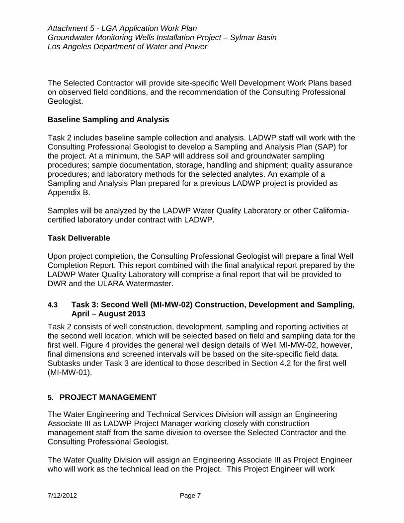
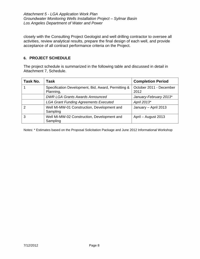
The Sylmar Groundwater Basin is located in the northerly part of ULARA (Figure 1), consists of 5,600 acres and comprises 4.6 percent of the total valley fill. It is bounded on the north and east by the San Gabriel Mountains; on the west by a topographic divide in the valley fill between the Mission Hills and the San Gabriel Mountains; on the southwest by the Mission Hills; on the east by the bedrock of Saugus Formation along the east bank of the Pacoima Wash; and on the south by the eroded south limb of the Little Tujunga Syncline, which separates it from the San Fernando Basin.1 The Mission Wellfield is located at 12210 Havana Avenue in the Sylmar community of Los Angeles, California (Figure 2). This wellfield currently includes two active groundwater supply wells, a groundwater storage tank, a booster pump station, a chlorine disinfection facility, and other related infrastructure.
2.2 Site History
The City of Los Angeles owns adjudicated rights to pump 3,405 acre feet per year from the Sylmar Groundwater Basin and approximately 15,000 acre feet in stored water credits accumulated from prior years of pumping below the annual allotment. On average over the last ten years, the LADWP has pumped only 65 percent (2,240 acre 1 From the Upper Los Angeles River Area Watermaster Services website, Description page: www.ularalwatermaster.com
Attachment 5 - LGA Application Work Plan Groundwater Monitoring Wells Installation Project – Sylmar Basin Los Angeles Department of Water and Power
7/12/2012 Page 2
feet per year) of its annual water right in the Sylmar Basin due to the presence of trichloroethene (TCE). Under the judgment agreement, parties retain stored water credits for only five years. Stored water credits older than five years can be deducted by the ULARA Watermaster. TCE has been detected in water samples from the Mission Wellfield since 1999. In 2008, TCE concentrations in one of the two active wells began and continued to exceed the California’s regulatory maximum contamination level (MCL) of 5 micrograms per liter (ug/L). Recent samples from this well have been found to contain concentrations as high as 9 ug/L. In the recent months, TCE concentrations in samples from the second well have risen and been detected at levels ranging between 2 and 4 ug/L.
3. PROJECT INFORMATION
3.1 General Project Description
The overall Groundwater Monitoring Wells Installation Project will encompass the installation, development and monitoring of 22 groundwater monitoring wells in the San Fernando Basin, up to five in the Central Basin, and up to five in the Sylmar Groundwater Basin. However, this LADWP application for LGA funding and the scope of this work plan are focused on the portion of the overall project that will be conducted in the Sylmar Basin. LADWP proposes to construct, develop, and sample two groundwater monitoring wells within the Sylmar Basin near the Mission Wellfield. The wells will provide additional data on the vertical and lateral extent of groundwater contamination affecting the operation of supply wells in the wellfield.
3.2 Goals and Objectives
Data from the two new monitoring wells will help define the lateral and vertical extent of TCE in groundwater in the vicinity of the Mission Wellfield. The new wells will include nested casings located in the same borehole to enable the collection and analysis of groundwater samples from different depths in the aquifer. These new data will assist LADWP in characterizing the vertical extent of contamination to inform decisions regarding the future operation of the wellfield. For example, LADWP could decide to install new water supply wells screened at greater depths if samples indicate the presence of deep, high-quality groundwater. Alternatively, the data may show that groundwater treatment is the best alternative. As needed, the resulting data could also help site additional groundwater wells or determine the appropriate treatment technology.

Attachment 5 - LGA Application Work Plan Groundwater Monitoring Wells Installation Project – Sylmar Basin Los Angeles Department of Water and Power
7/12/2012 Page 3
The LADWP’s ultimate objective in initiating this project is to develop a strategy to recover pumping capacity that has been lost in the Sylmar Basin due to the groundwater contamination. The project will also provide the following additional benefits: The new monitoring wells will serve as sentinel stations that provide an early
warning of contaminants which may emerge within the aquifer over time and eventually reach the Mission Wellfield.
Geophysical information obtained by the drilling process will broaden and increase the level of understanding of the Sylmar Basin geology, location and extent of the unconfined aquifer, confining layer (aquitard), and confined aquifer of the Saugus Formation.
Water elevation data from the new monitoring wells will provide the Watermaster additional information for evaluating safe yield of the Sylmar Basin and determining whether the basin is in overdraft.
4. PROJECT SCOPE OF WORK
As discussed previously, the scope of work for the Project consists of the construction, development, and sampling of two groundwater monitoring wells within the Sylmar Basin near the Mission Wellfield. The wells will provide additional data on the vertical and lateral extent of groundwater contamination affecting the operation of supply wells in the wellfield. Details regarding each project task are provided below.
4.1 Task 1: Specification Development, Bid, Award, Permitting & Planning, October 2011 - December 2012
Task 1 is currently on going and consists of specification development, bid, award, and other pre-construction activities for the Project. Because these activities will be completed prior to a grant award, they would not qualify as reimbursable expenses. However, Task 1 is included in the workplan, budget, and schedule in order to provide DWR with a complete picture of the Project. LADWP is seeking funding for the construction of one well, which would commence after the expected grant award date. LADWP staff is currently finalizing Specification 7315 for the Groundwater Monitoring Wells Installation Project, which encompasses wells in three different groundwater basins. Part F Section F02523 of the Specification is included as Appendix A and contains site construction requirements for the optional construction of up to five groundwater monitoring wells in the Sylmar Basin. Although identified as an optional task in the Specification, LADWP has definitive plans to drill at least two of these wells. This portion of the work planned in the Sylmar Basin is the Project that is the subject of this LGA grant application. Three additional wells may be installed at a later date if
Attachment 5 - LGA Application Work Plan Groundwater Monitoring Wells Installation Project – Sylmar Basin Los Angeles Department of Water and Power
7/12/2012 Page 4
warranted – data collected from the first two wells will be used to make this determination and site any subsequent wells – but are not considered to be within the scope of this Project. Task 1 includes the following subtasks, described in detail below:
Development of Specification
Bid and award of drilling services contract;
Public outreach;
CEQA compliance and permitting;
Contracting of a Consulting Professional Geologist; and
Preparation of workplans. Specification 7315 is being finalized and is expected to be advertised by July 2012. As detailed in Attachment 7, Project Schedule, the final award of the contract is expected to occur by October 2012. Construction of the first well could start as early as January 2013. Any funding awarded to the LADWP for this project would be applied towards construction of the second well, expected to begin in April 2013. DWR staff indicated during a LGA Workshop that Awards would be announced in January or February 2013, with funding agreements likely finalized by April or May. LADWP public relations staff will provide outreach to residents and businesses in the vicinity of the Mission Wellfield monitoring wells to notify them of Project construction activities and locations, provide updates, and maintain open communication with neighbors to identify and respond to impacts to the surrounding community. Public outreach activities will continue throughout Task 2 construction of the first well (MI-MW-01) and Task 3 construction of the second well (MI-MW-02). Task 1 includes pre-construction permitting and compliance with the California Environmental Quality Act (CEQA) and, as needed, the National Environmental Policy Act (NEPA). LADWP staff has determined that the project qualifies for a Categorical Exemption under CEQA and will work towards finalizing the necessary documentation before the overall project is awarded and before a funding agreement with DWR would have to be negotiated. LADWP staff will also work with the Consulting Professional Geologist to obtain additional local well drilling permits, as needed. LADWP will leverage existing on-call contracts to engage a Consulting Professional Geologist to oversee well drilling and sampling. LADWP will work with the Consulting Professional Geologist to develop site-specific Work Plan and a Sampling and Analysis Plan (SAP) for the project. At a minimum, the SAP will address soil and groundwater sampling procedures; sample documentation, storage, handling and shipment; quality assurance procedures; and an analyte list with laboratory methods. An example of an SAP prepared for a previous LADWP project is provided as Appendix B.
Attachment 5 - LGA Application Work Plan Groundwater Monitoring Wells Installation Project – Sylmar Basin Los Angeles Department of Water and Power
7/12/2012 Page 5
4.2 Task 2: First Well Construction (MI-MW-01), Development and Sampling, January – April 2013
Task 2 consists of well construction, development, sampling and reporting activities at the first well location. Figure 3 provides the general well design details for Well MI-MW-01, however, final dimensions and screened intervals will be based on the site-specific field data. Additional information on material requirements, drilling methods, and well design are provided in Appendix A. Technical Submittals and Plans This task also includes the preparation of submittals required per the Specification (see Appendix A, Item 1.05), site meetings, and other project coordination activities. The following plans will be prepared for each drill site: Sampling and Analysis Plans;
Site-specific health and safety plans;
Traffic Control Plan;
Wet Weather Erosion Plan;
Well Development Work Plan;
Drilling Mud Management Plan; and
Site Plan and Waste Management Work Plan.
Well Drilling and Construction Key well drilling and well construction subtasks are listed below. Site mobilization.
Installation of temporary sound barriers, work area traffic control signs, and barricades.
Use of air rotary and mud rotary drilling methods to drill boreholes to depths greater than 1,000 feet, as needed.
Collect and classify representative formation samples at 5-foot intervals throughout the pilot borehole and prepare drill logs.
Conduct geophysical logging of the pilot borehole.
Conduct in situ groundwater sampling.
Lab analysis of in situ groundwater samples for developing a water quality profile of the borehole and determining the location of well screen intervals.

Attachment 5 - LGA Application Work Plan Groundwater Monitoring Wells Installation Project – Sylmar Basin Los Angeles Department of Water and Power
7/12/2012 Page 6
Installation of steel conductor casings, polyvinyl chloride (PVC) well casings and screens, sand filters, Bentonite annular seals, and cement sanitary seals to the required depths.
Removal of drilling mud and fluids from the completed PVC well casings.
Lab analysis of waste stream samples for characterization and disposal purposes.
Proper management and disposal of drilling mud and fluids.
Installation of traffic-rated lids in the public right-of-way to cover the monitoring wells at the ground surface.
A plumbness and alignment survey of the finished well.
A video survey of the finished well.
Installation and testing of water quality sampling instruments and water level measuring devices.
Site demobilization. As provided in Item 1.08 of the Specification, all work will conform to American National Standards Institute/American Water Works Association (ANSI/AWWA) A100-06, DWR Southern District California Well Standards Bulletins 74-81 and 74-90, and well drilling permit requirements of the Los Angeles County Department of Public Health. Additional quality assurance requirements are provided in Attachment 8. Well Development Well development is needed to remove drilling fluid and mud from each well casing so as to reduce disturbances caused by the well drilling operations and ensure proper hydraulic connection between the new well and the aquifer materials adjacent to the well screen. Well development will be completed when turbidity is less than 10 NTU for a sustained period of pumping. This will ensure that samples collected from the monitoring well are representative of the aquifer. Potential well development methods are discussed in Appendix A and listed below:
Swabbing
Bailing
Air Lifting
Jetting
Chemical Development
Pumping and Surging
Attachment 5 - LGA Application Work Plan Groundwater Monitoring Wells Installation Project – Sylmar Basin Los Angeles Department of Water and Power
7/12/2012 Page 7
The Selected Contractor will provide site-specific Well Development Work Plans based on observed field conditions, and the recommendation of the Consulting Professional Geologist. Baseline Sampling and Analysis Task 2 includes baseline sample collection and analysis. LADWP staff will work with the Consulting Professional Geologist to develop a Sampling and Analysis Plan (SAP) for the project. At a minimum, the SAP will address soil and groundwater sampling procedures; sample documentation, storage, handling and shipment; quality assurance procedures; and laboratory methods for the selected analytes. An example of a Sampling and Analysis Plan prepared for a previous LADWP project is provided as Appendix B. Samples will be analyzed by the LADWP Water Quality Laboratory or other California-certified laboratory under contract with LADWP. Task Deliverable Upon project completion, the Consulting Professional Geologist will prepare a final Well Completion Report. This report combined with the final analytical report prepared by the LADWP Water Quality Laboratory will comprise a final report that will be provided to DWR and the ULARA Watermaster.
4.3 Task 3: Second Well (MI-MW-02) Construction, Development and Sampling, April – August 2013
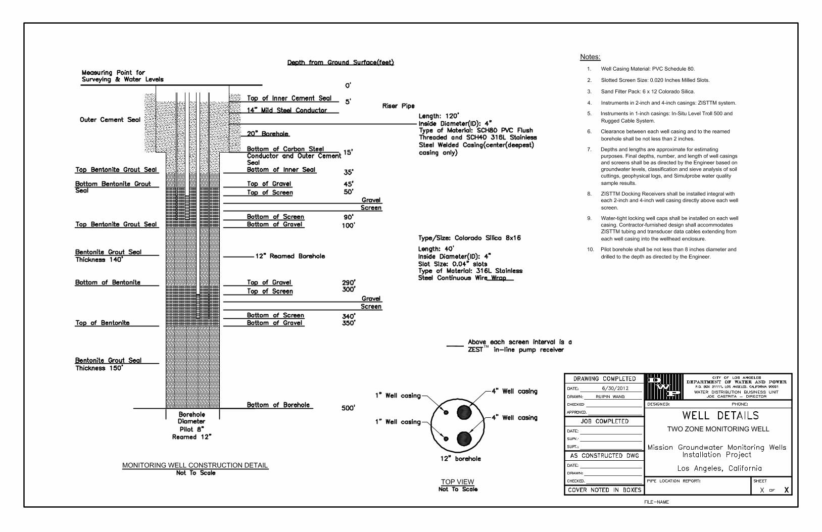
Task 2 consists of well construction, development, sampling and reporting activities at the second well location, which will be selected based on field and sampling data for the first well. Figure 4 provides the general well design details of Well MI-MW-02, however, final dimensions and screened intervals will be based on the site-specific field data. Subtasks under Task 3 are identical to those described in Section 4.2 for the first well (MI-MW-01).
5. PROJECT MANAGEMENT
The Water Engineering and Technical Services Division will assign an Engineering Associate III as LADWP Project Manager working closely with construction management staff from the same division to oversee the Selected Contractor and the Consulting Professional Geologist. The Water Quality Division will assign an Engineering Associate III as Project Engineer who will work as the technical lead on the Project. This Project Engineer will work
Attachment 5 - LGA Application Work Plan Groundwater Monitoring Wells Installation Project – Sylmar Basin Los Angeles Department of Water and Power
7/12/2012 Page 8
closely with the Consulting Project Geologist and well drilling contractor to oversee all activities, review analytical results, prepare the final design of each well, and provide acceptance of all contract performance criteria on the Project.
6. PROJECT SCHEDULE
The project schedule is summarized in the following table and discussed in detail in Attachment 7, Schedule.
Task No. Task Completion Period
1 Specification Development, Bid, Award, Permitting & Planning,
October 2011 - December 2012
DWR LGA Grants Awards Announced January-February 2013*
LGA Grant Funding Agreements Executed April 2013*
2 Well MI-MW-01 Construction, Development and Sampling
January – April 2013
3 Well MI-MW-02 Construction, Development and Sampling
April – August 2013
Notes: * Estimates based on the Proposal Solicitation Package and June 2012 Informational Workshop
Imagery ©2012 DigitalGlobe, GeoEye, U.S. Geological Survey, USDA Farm Service Agency -
To see all the details that are visible on the screen, use the "Print" link next to the map.
Page 1 of 112210 havana st - Google Maps
7/11/2012http://maps.google.com/maps?ie=UTF-8&hl=en&tab=wl
2010-2011 Water Year ULARA Watermaster
2000 0 2000 ,........, -
Ft't't
Upper Los Angeles River Area: Sylmar Groundwater Basin Map
Legend
D Approximate Groundwater Basin Boundary
• City of San Fernando Water Welt
• LADWP Water Well
"b Well with hydrograph in this report
PLATE 1B
Attachment 5 - LGA Application Work Plan Groundwater Monitoring Wells Installation Project – Sylmar Basin Los Angeles Department of Water and Power
7/12/2012
APPENDIX A
Specification 7315
Part F – Detailed Specifications Division F2 – Site Construction
Section F02523 – Monitoring Wells in Sylmar Basin
Spec. 7315
F02523 Page 1 of 37
PART F - DETAILED SPECIFICATIONS DIVISION F2 – SITE CONSTRUCTION
SECTION F02523 – MONITORING WELLS IN SYLMAR BASIN
PART 1 - GENERAL
1.01 RELATED DOCUMENTS
A. For an understanding of the complete contract, reference is made to a statement of the Contract Documents in Division D1.
1.02 SUMMARY
A. Optional work to construct up to 5 groundwater monitoring wells in the Sylmar Basin, which is located in Los Angeles County, California.
1.03 RELATED SECTIONS
A. Section F01330 – Submittals.
B. Section F01322 – Record Documents.
C. Section F01780 – Operation and Maintenance Manuals.
1.04 REFERENCES
A. American National Standards Institute/American Water Works Association (ANSI/AWWA) A100-06.
B. California Department of Water Resources Southern District (CDWR) California Well Standards Bulletins 74-81 and 74-90.
C. American Society for Testing and Materials (ASTM) Annual Book of ASTM Standards.
D. Standard Specifications for Public Works Construction (SSPWC) and the additions and supplements of the City of Los Angeles (“Brown Book”).
E. United States Environmental Protection Agency (USEPA) Groundwater Issue Paper #EPA 542-S-02-001 “Ground-Water Sampling Guidelines for Superfund and RCRA Project Managers”, (Yeskis and Zavala, May 2002).
Spec. 7315 SECTION F02523 MONITORING WELLS IN SYLMAR BASIN
F02523 Page 2 of 37
F. USEPA Groundwater Issue Paper #EPA 540-S-95-504 “Low-Flow (Minimal Drawdown) Ground Water Sampling Procedures”, (Puls and Barcelona, April 1996).
G. American Welding Society (AWS) “Welding Handbook”.
H. American Petroleum Institute (API), Spec 10A.
I. Guidance Document for the NPDES Discharge Permit, Number CAG994005, CI-9255 for the Mission Wellfield Groundwater Study Project.
J. Guidance Document for the Industrial Waste Discharge Permit Number W-496163 for Mission Wellfield Sanitary Sewer as used by the Mission Wellfield Groundwater Study Project.
K. Guidance Document for the Industrial Waste Discharge Permit Number W-208712 for Van Nuys Service Center as used by the Groundwater System Improvement Study (GSIS).
L. American National Standards Institute/American Petroleum Institute (ANSI/API) RP 13B-1: Recommended Practice for Field Testing Water-Based Drilling Fluid.
1.05 SUBMITTALS
A. Submit the following in accordance with Section F01330:
1. Completed and signed “Los Angeles Department of Water and Power Wet Weather Erosion and Sediment Control Plan” template for each drill site.
2. Drilling Mud Management Plan for each drill site: Designed by a qualified mud engineer and stamped by a registered professional geologist. Include proposed equipment and layout, conveyance piping, power supply, materials, and additives proposed for use in the drill mud, and procedures for managing drill mud properties.
3. Site Plan and Waste Management Work Plan for each drill site. Include layout of drill rig, support rig, equipment, waste storage containers, roll-off bins, and tanks. Include disposal sites, operating hours for transportation of waste materials, and anticipated maximum truck trips per day. Describe method for facilitating public access, refuse
Spec. 7315 SECTION F02523 MONITORING WELLS IN SYLMAR BASIN
F02523 Page 3 of 37
collection from neighboring properties, and other property access needs.
4. Certifications and Material Safety Data Sheets (MSDS) of all proposed drilling mud additives.
5. Company name and qualifications of the geophysical borehole logging subcontractor demonstrating the following experience:
a. Not less than 5 years conducting the required suite of geophysical logging on boreholes similar in scope to this contract.
b. Conducting and interpreting geophysical logging for public agencies or for groundwater investigations in the groundwater basins of the Los Angeles area.
c. Calibrating geophysical logging tools.
6. Mix design of cement grout to be installed in the annular space exterior to the conductor casing.
7. Mix design of the annular seal and sanitary seal to be installed in the annular space exterior to the PVC well casings.
8. Certificate of sand filter pack material quality and gradation, including sieve analysis of representative samples from each batch delivered to each site.
9. Manufacturer’s certification of conductor casing materials conforming to ASTM A139 or ASTM A53.
10. Manufacturer’s documentation of PVC well casing materials certifying conformance to ASTM D1785 and ASTM F480 and documenting the source of resin materials used in the manufacture of PVC well casing materials supplied for this contract.
11. Material list and working drawings of the well casing assembly and incorporated components of the Zone Isolation Sampling Technology (ZISTTM) system approved by the manufacturer. Certify compatibility of the well casing sections with the ZISTTM on the working drawings by signature of the Contractor and the authorized representative of BESST, Inc.

Spec. 7315 SECTION F02523 MONITORING WELLS IN SYLMAR BASIN
F02523 Page 4 of 37
12. Surface completion material list and working drawings. Include installation details for EMCO Wheaton Retail A0721-218 Manhole, EMCO Wheaton Retail A0717-124B Manhole, locking covers, and watertight locking well casing caps. Clearly show transducer data cables and ZISTTM tubing are accessible within the vault enclosure.
13. Well Development Work Plan for each drill site. Include all well development processes, methods, equipment and layout, tools, holding tank(s), conveyance piping, and MSDS of dispersants.
14. Manifests for solid and liquid waste disposal to permitted waste disposal facilities approved by the Engineer for the project. Obtain the Engineer’s signature on manifests prior to transporting wastes from each site. Arrange for one original of each waste manifest to be signed and mailed to the Engineer by the waste disposal facility operator certifying receipt of wastes for disposal.
15. As-constructed drawings of each completed well as specified in Subarticle 3.05J of this Section.
16. Wastewater Treatment Work Plan (required only if Option Item 113 is exercised). Include all components and layout of the temporary granular activated carbon wastewater treatment system and operating procedures.
B. Submit Operation and Maintenance Manuals as defined in Section F01780 for all instruments.
1. Provide a summary of all settings of each instrument and procedures for unit re-calibration.
2. O&M manuals for ZISTTM systems shall include a record of all cycle times for operating the ZISTTM Multi-Zone Timer Controller in Purging Mode and Sampling Mode recommended for the operation of each ZISTTM pump as installed in each completed well.
1.06 MANUFACTURER’S WARRANTIES
A. Provide the following manufacturer’s warranties, which shall commence on Final Acceptance:
1. ZISTTM System: 5 years.
Spec. 7315 SECTION F02523 MONITORING WELLS IN SYLMAR BASIN
F02523 Page 5 of 37
2. In-Situ Products, including Level Troll 500, Rugged Cable System: 5 years.
1.07 NOT USED
1.08 GENERAL REQUIREMENTS
A. All work shall conform to the following requirements:
1. American National Standards Institute/American Water Works Association (ANSI/AWWA) A100-06.
2. California Department of Water Resources Southern District (CDWR) California Well Standards Bulletins 74-81 and 74-90.
3. Well drilling permit requirements of the Los Angeles County Department of Public Health.
1.09 ADDITIONAL SERVICES
A. The Engineer reserves the right to issue Change Orders directing the Contractor to provide any of the following additional services:
1. Well removal, abandonment, and destruction:
a. Clean the well to remove undesirable materials and obstructions. Remove conductor casing and annular seal to a depth not less than 20 feet below ground surface.
b. Place low permeability sealing material, such as sand cement or Bentonite grout. Place materials under pressure using a tremie pipe to prevent freefall, bridging, and dilution of sealing material through the borehole. Place materials continuously throughout the interval being filled to within 5 feet below ground surface. Backfill the final 5 feet with cement slurry.
c. Furnish a record of all well destruction procedures in accordance with Section F01322.
d. Change Orders will not be issued for terminating and destroying borehole(s) if such termination is due to Contractor negligence.

Spec. 7315 SECTION F02523 MONITORING WELLS IN SYLMAR BASIN
F02523 Page 6 of 37
2. Well maintenance, including removal and replacement of instrumentation.
3. Well Redevelopment: Remobilize and perform additional well development beyond the work required in Article 3.07 of this Section.
4. Video survey.
PART 2 – PRODUCTS
2.01 CONDUCTOR CASING
A. Manufactured in accordance with ASTM A 139 Grade B or ASTM A 53 Grade B.
B. Welding shall be by the automatic submerged-arc process using not less than one pass on the interior surface and not less than one pass on the exterior surface.
C. Inside diameter as directed by the Engineer, lengths of not less than 10 feet, and wall thickness of not less than 0.25 inch.
D. The ends of each joint shall be machine beveled perpendicular to the casing axis to ensure the straightness of each assembled section. One end of each assembled section shall be fitted with a 6-inch wide collar welded to the pipe so that the collar will be equally spaced on either side of the joint. Provide 3 equally spaced alignment holes in each collar.
2.02 WELL CASINGS
A. General Requirements:
1. Manufactured in accordance with ASTM D 1785 and ASTM F 480.
2. Schedule 80 Polyvinyl Chloride (PVC) in lengths of not less than 10 feet.
3. One-inch, 2-inch, and 4-inch diameter blank section well casings in total lengths required for installation to one or more zones below ground surface as directed by the Engineer.
Spec. 7315 SECTION F02523 MONITORING WELLS IN SYLMAR BASIN
F02523 Page 7 of 37
4. Flush threaded symmetrical with the well casing wall thickness.
5. O-ring seals: Viton material, sized to seat properly within the o-ring groove of the flush threaded connection without the need for over-stretching the o-ring.
6. Compatible with the components of the ZISTTM system which shall be incorporated into the completed assembly of the well casing.
B. PVC Slotted Well Screens:
1. Schedule 80 Polyvinyl Chloride (PVC).
2. The slotted well screens shall be 0.020 inches milled slots, or as otherwise directed by the Engineer, based on the results of the Contractor’s sieve analysis of representative formation samples from the pilot borehole.
3. One-inch, 2-inch, and 4-inch slotted well screens in total lengths of 40 feet as directed by the Engineer for installation in each of one or more zones.
4. Install 10 feet of blank well casing below each interval of slotted well screens, fitted with a closed shoe or plug.
2.03 SAND FILTER PACK
A. “6 x 12 Colorado Silica” Oglebay Norton Industrial Sand filter pack material, or alternate gradation as directed by the Engineer based on results of the Contractor’s sieve analysis of formation samples collected from the pilot borehole.
B. Hard, well-rounded siliceous rock or water-worn sand and gravel. Wash clean of dirt, silt, clay, organic material, and other foreign substances. Do not furnish crushed rock or pea gravel.
C. Contain not less than 80 percent silica content and not more than 5 percent calcareous materials.
D. Specific Gravity: 2.5 or greater.
Spec. 7315 SECTION F02523 MONITORING WELLS IN SYLMAR BASIN
F02523 Page 8 of 37
E. Keep free of debris and all foreign matter at all times.
2.04 TRANSITION SEAL
A. Seal above sand filter pack material shall consist of 100 percent Baroid bentonite clay pellets or chips.
2.05 ANNULAR SEAL AND SANITARY SEAL
A. Annular Seal for Steel Conductor Casing:
1. Used to seal the exterior annular space.
2. ASTM C 150 Type II (API Class B) cement.
3. Mix Design: Sand-cement grout equivalent to a 10.3-sack mix.
4. If used, additives mixed with the sealing material to accelerate the curing time or to expand the material shall not exceed the following:
a. 2 percent calcium chloride.
b. 4 percent bentonite.
B. Annular Seal for PVC Well Casings:
1. Used to seal the exterior annular space below the surface sanitary seal.
2. Mix Design: Equal parts Baroid Bentonite granular clay and sand, dry mixed prior to placement.
3. Sand material: Medium grain size passing the U.S. Standard Sieve mesh #35 and retained in the U.S. Standard Sieve mesh #60, and consist of rounded, non-reactive material. Do not furnish crushed aggregate.
4. Do not add additives to accelerate the cure time.
C. Sanitary Surface Seal:
1. Used to seal the exterior annular space of the PVC well casings below the final ground surface.
2. Mix Design: ASTM C150 Type II (API Class B) cement with up to 6 percent Baroid bentonite clay.
Spec. 7315 SECTION F02523 MONITORING WELLS IN SYLMAR BASIN
F02523 Page 9 of 37
3. Do not use additives to accelerate the cure time.
2.06 INSTRUMENTATION
A. ZISTTM - Option Items 100 through 105:
1. Manufacturer: BESST, Inc.
2. Provide all components necessary for the intended use of collecting groundwater samples under low-flow and minimal drawdown conditions, including ZISTTM Docking Receivers, Blatypus Pumps, Blatymini Pumps, ZISTTM Docking Weights with Viton o-rings, Perforated Drop-Tube Extensions, volume displacement stems, system pressurization and sample-return 3/8-inch x 1/4-inch tubings, ZISTTM Centralizers, well-head assemblies, and programming schedule for ZISTTM Multi-Zone Timer Control Unit.
3. Modify system configuration and components to suit the site-specific requirements and conditions for each monitoring well at the direction of the Engineer.
B. In-Situ Level Troll 500 (Non-Vented) – Option Item 106:
1. Manufacturer: In-Situ, Inc.
2. Measurement/Recording Capability: Water level, temperature, and date and time of day (Data Set).
3. Requirements:
a. Diameter: Not less than 0.72 inches.
b. Length: Not to exceed 8.5 inches.
c. Housing: Sealed within a waterproof Type 316 stainless steel or titanium housing.
d. Measurement and Recording Frequency: Capability to record one Data Set every second.
e. Operating Temperature: 32F to 86F.
f. Pressure Range - Pressure Sensor: Sensitivity range adjustable from minimum of 0 to 30 PSIA to maximum of 0 to 100 PSIA.
Spec. 7315 SECTION F02523 MONITORING WELLS IN SYLMAR BASIN
F02523 Page 10 of 37
g. Accuracy - Pressure Sensor: ±0.1 percent of full scale output or better.
h. Memory: One megabyte of non-volatile memory, or greater.
i. Internal Power: Internal battery shall provide a useful life of not less than 5 years or record not less than 2 million Data Sets during the life of the battery. Battery shall not corrode or leak during its useful life.
j. External Power: Transducer/Data Logger shall be readily adaptable to be powered by an external power supply or battery pack connected to the opposite end of the data cable.
C. In-Situ Rugged Cable System (Non-Vented) – Option Item 107:
1. Manufacturer: In-Situ, Inc.
2. Cable Lengths: As required for installation in each Zone as directed by the Engineer.
3. Requirements:
a. Diameter: Not greater than 0.72 inches.
b. External Cable Material: Teflon, non-volatile material that releases no chemicals to the surrounding environment.
c. Cable Strength: 138 lb minimum break strength.
d. Connector Fittings: Twist-lock connections. Fittings shall be able to support a tensile load of 50 lbs or more. Waterproof to a depth of 700 feet.
2.07 DRILLING EQUIPMENT
A. Drilling Techniques:
1. Air-rotary for the pilot borehole above the water table.
2. Direct mud-rotary or reverse circulation for the pilot borehole below the water table.
Spec. 7315 SECTION F02523 MONITORING WELLS IN SYLMAR BASIN
F02523 Page 11 of 37
3. Direct mud-rotary or reverse circulation for reaming the pilot borehole.
B. Drill Rig Capacity: Able to lift 2 times the weight of the drill string or the length of the well casing assembly, whichever is greater, and able to drill to not less than 1,500 feet.
C. Drill Pipe: In good condition and connected by standard tool or flange-type joints. Reverse rotary drill pipe, if used, shall be a minimum diameter of 6 inches and able to accommodate a flow of not less than 600 gallons per minute (gpm) of drilling mud.
D. Clean and decontaminate the drill rig prior to arriving at each site. Clean the rig and other equipment to the satisfaction of the Engineer prior to the start of drilling.
E. Place a continuous layer of visqueen or similar impervious material beneath the drill rig. Provide an elevated berm or edge for spill containment.
F. Equip with drilling mud measuring equipment conforming to standards of the American Petroleum Institute.
G. Lubricate drill string connections or threads using Teflon, vegetable-based materials, or KOPR-KOTE (lead free) heavy duty drill pipe compound.
2.08 MANAGEMENT OF DRILLING MUD
A. Manage drilling mud properties to ensure removal of drill cuttings from the borehole, recover representative formation samples, maintain borehole stability, and maximize the efficiency of subsequent well development activities.
B. Drilling Mud Characteristics:
1. Weight: 8.7 to 9.2 pounds per gallon (lbs/gal) normal range, not to exceed 9.4 lbs/gal.
2. Maximum Funnel Viscosity: 38 seconds per quart.
3. Maximum 30-Minute Water Loss: 15 cubic centimeters.
4. Maximum Filter Cake: 3/32-inch.
Spec. 7315 SECTION F02523 MONITORING WELLS IN SYLMAR BASIN
F02523 Page 12 of 37
5. Maximum Sand Content of Drill Mud Entering the Borehole: 2 percent by volume.
6. Maximum Total solids content: 8 percent.
7. pH: 8.0 to 9.0 pH units.
8. Reverse circulation drilling methods shall utilize fresh-water based drilling fluid only.
C. Drilling Mud Additives, if used, may include:
1. Baroid Aqua-Gel, Quik-Gel, or other high-grade National Science Foundation (NSF)-certified biodegradable chemical products.
2. Drispac Super Low (Polyanionic Cellulose Polymer).
3. Polymers.
4. Bentonite.
5. Deliver to the drill site in factory labeled and sealed containers for Engineer’s inspection before use.
D. Equipment:
1. Utilize a shale shaker with desanders and desilters, fully capable of handling the volume of the drilling mud and removing drill cuttings.
2. Mud tanks: Adequately baffled to settle drill cuttings and to minimize the re-circulation of silt and clay back into the borehole. Clean tanks as necessary to ensure proper maintenance of drilling mud.
3. Mud tanks and conveyance piping shall be watertight.
E. Tests:
1. Test drilling mud properties hourly and when conditions change. Conduct additional tests as required by the Engineer. Furnish one copy of documented results of each test to the Engineer.
2. Tests on drill mud properties shall conform to ANSI/API RP 13B-1 and include funnel viscosity,
Spec. 7315 SECTION F02523 MONITORING WELLS IN SYLMAR BASIN
F02523 Page 13 of 37
weight, sand content, 30-minute water loss, pH, and wall cake thickness.
3. If tests indicate that properties are not within the limits required for Drilling Mud Characteristics, immediately suspend drilling operations and recondition or replace the mud to achieve these standards.
F. Non-Compliant Practices:
1. Drilling with a mixture of water and unprocessed mud, clay, or other material.
2. Brown bag drilling fluid substitutes or organic drilling additives, such as Cellex or CMC.
3. Excavated or below-grade mud pits.
4. If the Engineer determines that drilling mud properties have not been properly controlled, the Contractor may be required to provide a qualified mud engineer to supervise and ensure the maintenance of drilling mud properties.
2.09 MONITORING WELL COVER
A. Borehole Diameter 18 Inches or Less:
1. EMCO Wheaton Retail, Model A0721-218.
a. Skirt: Heavy Duty, 100 percent welded steel.
b. Cover: Unpainted, with A0720-001 locking cap and collar, and LADWP Identification Tag.
B. Borehole Diameter 20 Inches or Greater: EMCO Wheaton Retail, Model A0717-124B. Skirt: Heavy Duty, 100 percent welded steel.
PART 3 – EXECUTION
3.01 WET WEATHER EROSION AND SEDIMENT CONTROL PLAN
A. Prevent contamination resulting from construction activities from entering the stormwater.
Spec. 7315 SECTION F02523 MONITORING WELLS IN SYLMAR BASIN
F02523 Page 14 of 37
B. Prevent the spill of drilling mud, development water, and other liquid substances. Immediately contain and clean up spills and notify the Engineer.
C. Prevent the discharge of sediments from portable pumps and hoses by using inlet screens, burlap sacks on hose outlets, sand-bag sediment traps, and control of pump flow rates.
D. Sweep work areas at the end of each work day.
E. Cover drill cuttings and other solid wastes contained on site or in laydown areas.
F. Place drip pans or absorbent materials under equipment.
G. Place and secure geotextile fabric over storm drain inlets potentially affected by any waste stream or storm runoff from the work area.
3.02 CONDUCTOR CASING INSTALLATION
A. Drill a borehole with a diameter directed by the Engineer to a depth not less than 50 feet.
B. Set the conductor casing accurately centered and plumb in the drilled hole.
C. Lap-weld all field joints with not less than 2 passes per circumference. Provide steel guides, attached near the base of and 5 feet below the top of the casing, to center and hold the casing in the proper position until the grout seal is in place.
D. Field weld by the metal-arc method or gas-shielded arc method as described in the AWS “Welding Handbook” as supplemented by other pertinent standards of the AWS. Qualification of welders shall be in accordance with the AWS Standards.
E. Place cement grout in the annular space exterior to the conductor casing. Pump continuously using pressure grouting techniques and a tremie pipe until the annular space is filled to the required depth below ground surface as directed by the Engineer.
F. If the borehole collapses prior to placement of the grout seal, reopen the borehole and place the cement
Spec. 7315 SECTION F02523 MONITORING WELLS IN SYLMAR BASIN
F02523 Page 15 of 37
grout seal. Such remedial action shall require the Engineer’s approval.
G. Allow cement grout to cure for not less than 12 hours before drilling the pilot borehole below the conductor casing.
H. Obtain soil samples from the conductor casing borehole every 10 feet as directed by the Engineer. Furnish soil samples to the Engineer for laboratory analyses and characterization of the solid waste for disposal purposes.
3.03 PILOT BOREHOLE DRILLING AND GEOPHYSICAL BOREHOLE LOGGING
A. Drill an 8-inch pilot borehole to a depth directed by the Engineer.
1. Use air rotary drilling methods above the water table.
2. Use direct mud rotary drilling methods below the water table.
3. To address noise impacts to surrounding properties, the Engineer reserves the right to issue Change Orders directing the Contractor to immediately discontinue air rotary drilling and to switch drilling methods.
B. Soil Sampling - Option Item 96:
1. Perform soil sampling during the drilling of the pilot borehole using split-spoon sampling equipment and procedures. Collect samples above the water table at elevations directed by the Engineer.
2. Split-spoon soil sampling shall conform to ASTM D 1586-98 “Standard Test Method for Penetration Test and Split-Barrel Sampling of Soil.”
3. Soil samples: Undisturbed in-situ, not less than 2 inches diameter by 18 inches long per sample.
4. Prior to drilling the pilot borehole, submit a soil sampling plan, including soil sampling equipment and procedures.
C. In-situ Groundwater Sampling - Option Item 97:
Spec. 7315 SECTION F02523 MONITORING WELLS IN SYLMAR BASIN
F02523 Page 16 of 37
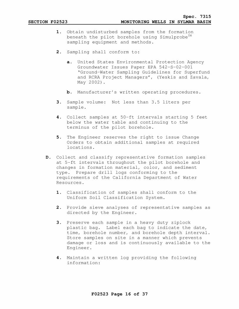
1. Obtain undisturbed samples from the formation beneath the pilot borehole using SimulprobeTM sampling equipment and methods.
2. Sampling shall conform to:
a. United States Environmental Protection Agency Groundwater Issues Paper EPA 542-S-02-001 “Ground-Water Sampling Guidelines for Superfund and RCRA Project Managers”, (Yeskis and Zavala, May 2002).
b. Manufacturer’s written operating procedures.
3. Sample volume: Not less than 3.5 liters per sample.
4. Collect samples at 50-ft intervals starting 5 feet below the water table and continuing to the terminus of the pilot borehole.
5. The Engineer reserves the right to issue Change Orders to obtain additional samples at required locations.
D. Collect and classify representative formation samples at 5-ft intervals throughout the pilot borehole and changes in formation material, color, and sediment type. Prepare drill logs conforming to the requirements of the California Department of Water Resources.
1. Classification of samples shall conform to the Uniform Soil Classification System.
2. Provide sieve analyses of representative samples as directed by the Engineer.
3. Preserve each sample in a heavy duty ziplock plastic bag. Label each bag to indicate the date, time, borehole number, and borehole depth interval. Store samples on site in a manner which prevents damage or loss and is continuously available to the Engineer.
4. Maintain a written log providing the following information:

Spec. 7315 SECTION F02523 MONITORING WELLS IN SYLMAR BASIN
F02523 Page 17 of 37
a. Material types, color, consistency or packing, grain size distribution estimates, and admixtures.
b. Depth and composition of each soil sample processed for sieve analysis.
c. Depth to the top and bottom of each stratification and sieve analysis results per interval.
d. Start and stop times of: Drilling, soil and water sample collection, and geophysical logging. Record drill penetration rates and explanations for any stoppage of the drilling process.
e. Maintain logs on site at all times and furnish 3 copies of the completed logs to the Engineer.
E. Geophysical Logging of the Pilot Borehole:
1. Conduct upon completion of the borehole.
2. Acceptance: Conduct a second set of logs on a repeat section of 100 feet, through a continuous water bearing zone below the water table as directed by the Engineer. If the logs for the repeat section are not identical with the main log for the same region, recalibrate the logging tools and re-log the entire borehole.
3. Record the response curves to show adequate deflections for evaluation of penetrated formations. The vertical scale shall be minimum one inch equals 50 feet for the response curve logs. Furnish the geophysical logs in accordance with Section F01322.
4. Include the following tests:
a. Short Normal Resistivity.
b. Long Normal Resistivity.
c. Single Point Resistivity.
d. Guard Log.
e. Natural Gamma.
Spec. 7315 SECTION F02523 MONITORING WELLS IN SYLMAR BASIN
F02523 Page 18 of 37
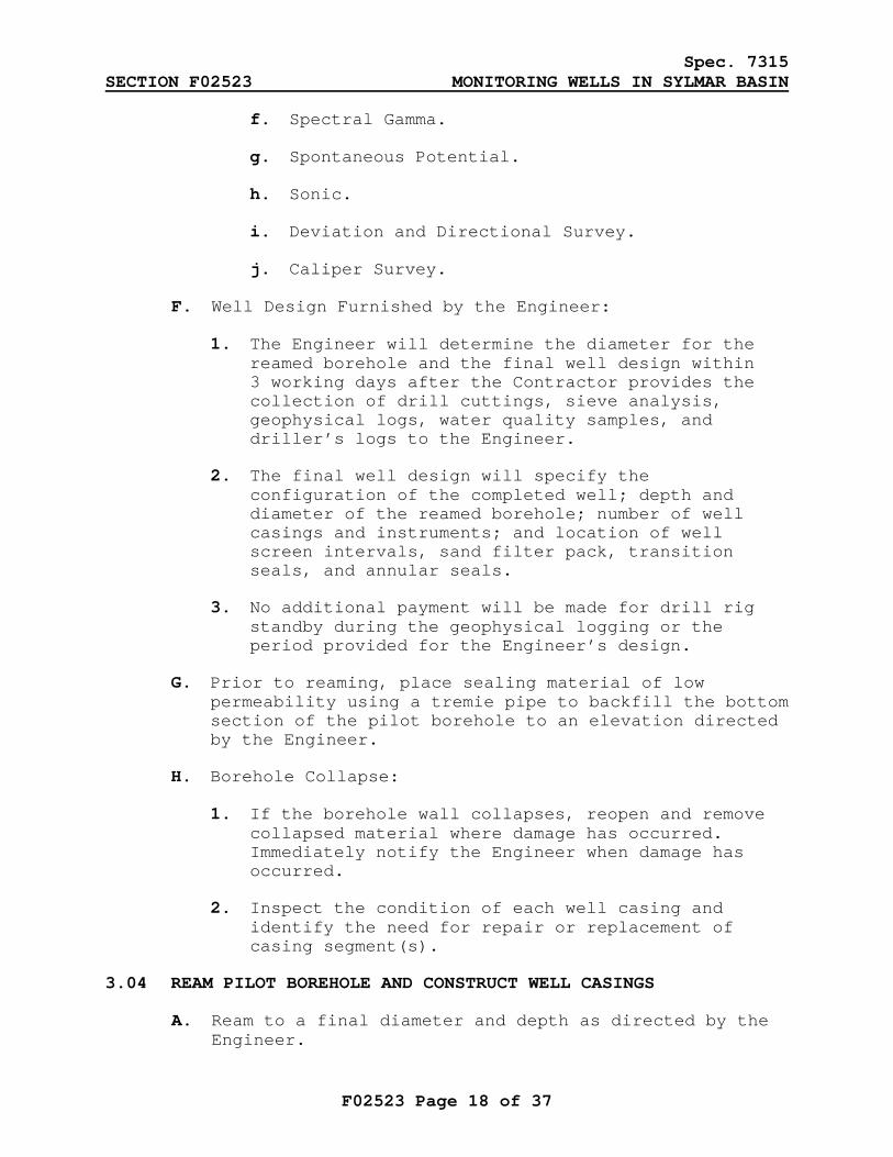
f. Spectral Gamma.
g. Spontaneous Potential.
h. Sonic.
i. Deviation and Directional Survey.
j. Caliper Survey.
F. Well Design Furnished by the Engineer:
1. The Engineer will determine the diameter for the reamed borehole and the final well design within 3 working days after the Contractor provides the collection of drill cuttings, sieve analysis, geophysical logs, water quality samples, and driller’s logs to the Engineer.
2. The final well design will specify the configuration of the completed well; depth and diameter of the reamed borehole; number of well casings and instruments; and location of well screen intervals, sand filter pack, transition seals, and annular seals.
3. No additional payment will be made for drill rig standby during the geophysical logging or the period provided for the Engineer’s design.
G. Prior to reaming, place sealing material of low permeability using a tremie pipe to backfill the bottom section of the pilot borehole to an elevation directed by the Engineer.
H. Borehole Collapse:
1. If the borehole wall collapses, reopen and remove collapsed material where damage has occurred. Immediately notify the Engineer when damage has occurred.
2. Inspect the condition of each well casing and identify the need for repair or replacement of casing segment(s).
3.04 REAM PILOT BOREHOLE AND CONSTRUCT WELL CASINGS
A. Ream to a final diameter and depth as directed by the Engineer.
Spec. 7315 SECTION F02523 MONITORING WELLS IN SYLMAR BASIN
F02523 Page 19 of 37
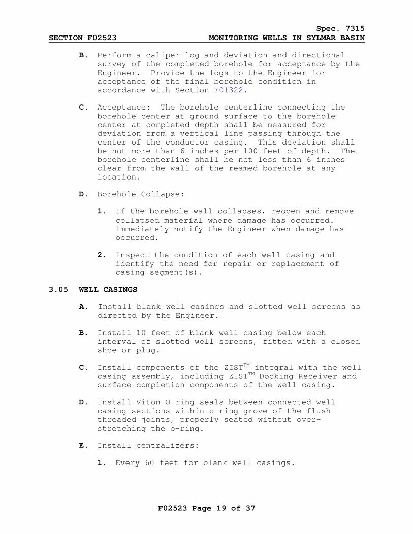
B. Perform a caliper log and deviation and directional survey of the completed borehole for acceptance by the Engineer. Provide the logs to the Engineer for acceptance of the final borehole condition in accordance with Section F01322.
C. Acceptance: The borehole centerline connecting the borehole center at ground surface to the borehole center at completed depth shall be measured for deviation from a vertical line passing through the center of the conductor casing. This deviation shall be not more than 6 inches per 100 feet of depth. The borehole centerline shall be not less than 6 inches clear from the wall of the reamed borehole at any location.
D. Borehole Collapse:
1. If the borehole wall collapses, reopen and remove collapsed material where damage has occurred. Immediately notify the Engineer when damage has occurred.
2. Inspect the condition of each well casing and identify the need for repair or replacement of casing segment(s).
3.05 WELL CASINGS
A. Install blank well casings and slotted well screens as directed by the Engineer.
B. Install 10 feet of blank well casing below each interval of slotted well screens, fitted with a closed shoe or plug.
C. Install components of the ZISTTM integral with the well casing assembly, including ZISTTM Docking Receiver and surface completion components of the well casing.
D. Install Viton O-ring seals between connected well casing sections within o-ring grove of the flush threaded joints, properly seated without over-stretching the o-ring.
E. Install centralizers:
1. Every 60 feet for blank well casings.
Spec. 7315 SECTION F02523 MONITORING WELLS IN SYLMAR BASIN
F02523 Page 20 of 37
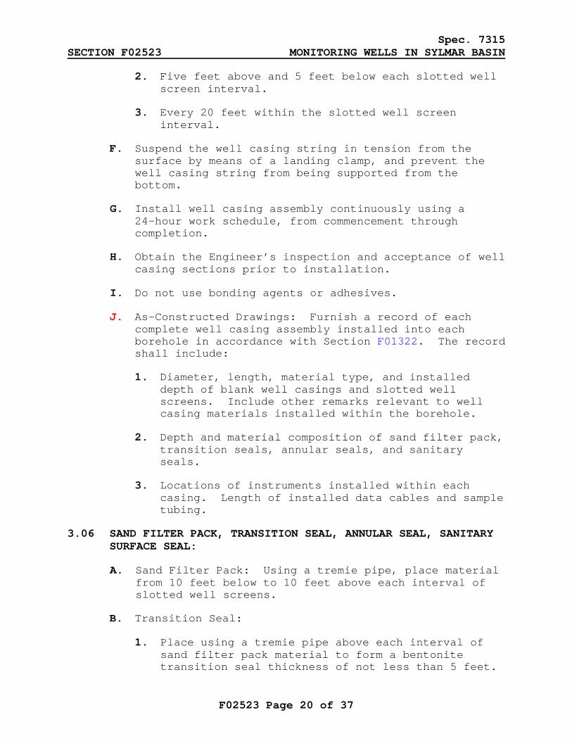
2. Five feet above and 5 feet below each slotted well screen interval.
3. Every 20 feet within the slotted well screen interval.
F. Suspend the well casing string in tension from the surface by means of a landing clamp, and prevent the well casing string from being supported from the bottom.
G. Install well casing assembly continuously using a 24-hour work schedule, from commencement through completion.
H. Obtain the Engineer’s inspection and acceptance of well casing sections prior to installation.
I. Do not use bonding agents or adhesives.
J. As-Constructed Drawings: Furnish a record of each complete well casing assembly installed into each borehole in accordance with Section F01322. The record shall include:
1. Diameter, length, material type, and installed depth of blank well casings and slotted well screens. Include other remarks relevant to well casing materials installed within the borehole.
2. Depth and material composition of sand filter pack, transition seals, annular seals, and sanitary seals.
3. Locations of instruments installed within each casing. Length of installed data cables and sample tubing.
3.06 SAND FILTER PACK, TRANSITION SEAL, ANNULAR SEAL, SANITARY SURFACE SEAL:
A. Sand Filter Pack: Using a tremie pipe, place material from 10 feet below to 10 feet above each interval of slotted well screens.
B. Transition Seal:
1. Place using a tremie pipe above each interval of sand filter pack material to form a bentonite transition seal thickness of not less than 5 feet.
Spec. 7315 SECTION F02523 MONITORING WELLS IN SYLMAR BASIN
F02523 Page 21 of 37
2. Measure the depths to the bottom and top of each interval before and after placement of each bentonite transition seal.
C. Annular Seal:
1. Install below the sanitary surface seal and above and below the intervals of sand filter pack materials and bentonite transition seals.
2. Place continuously until the desired depth is reached for the interval to be grouted.
3. Measure the depths to the bottom and top of each interval before and after placement of the sand-bentonite grout seals.
4. Pump into the annular space using pressure grouting techniques and a tremie pipe. Maintain tremie position at the bottom of the annular space; at no time shall grout material fall freely from the tremie to the elevation where grout material is being placed.
D. Sanitary Surface Seal: Place using a tremie pipe within the interval from the ground surface to 50 feet below ground surface around the well casings.
E. Install sand filter pack, transition seals, and annular seals continuously using a 24-hour per day work schedule, from commencement through completion.
F. Borehole Collapse:
1. If the borehole wall collapses, reopen and remove collapsed material where damage has occurred. Immediately notify the Engineer when damage has occurred.
2. Inspect the condition of each well casing and identify the need for repair or replacement of casing segment(s).
3.07 WELL DEVELOPMENT
A. Perform the following at the direction of the Engineer:
1. Swabbing.
Spec. 7315 SECTION F02523 MONITORING WELLS IN SYLMAR BASIN
F02523 Page 22 of 37
2. Bailing.
3. Air Lifting.
4. Jetting.
5. Chemical Development.
6. Pumping and Surging.
B. General Requirements:
1. Perform well development procedures on each 2-inch and 4-inch well casing completed to each zone.
2. Remove all debris from one-inch piezometer well casings by flushing with potable water, airlifting, and other feasible methods, or as directed by the Engineer.
3. Begin well development procedures not less than 24 hours after sanitary surface seal placement is complete and not later than 72 hours thereafter.
4. Begin each subsequent well development procedure not later than 24 hours after the preceding method is complete.
5. Upon completion of all development operations, demonstrate that the well is clear of all sand, mud, and other foreign material through the bottom of each well casing.
6. Furnish a record of all development work in accordance with Section F01322. Include start time, duration, and observed results of each method utilized.
C. Swabbing and Bailing:
1. Swab Tools: Close-fitting single-swab and double-swab tools with a clearance not to exceed 1/4-inch to the inside wall of the well casing.
2. Bailer: A suction bailer with adequate volume to efficiently remove accumulated material from the base of each well casing.
Spec. 7315 SECTION F02523 MONITORING WELLS IN SYLMAR BASIN
F02523 Page 23 of 37
3. Operate the swabbing tool to develop the full length each slotted well screen using a length of travel in short increments not to exceed 10 feet.
4. Measure the unobstructed depth inside the well casing to determine the level of accumulated sediment and bail or air-lift to remove the sediment to the full depth of the well casing.
5. Acceptance: Until sand and mud washed from the well casing, sand filter, and surrounding formation diminishes to the satisfaction of the Engineer.
D. Development by Air-lifting:
1. Tools: Air compressor with an air line, and inductor pipe and eductor pipe assembly equipped with dual swabs.
2. Operate air-lifting tool over the full length of each slotted well screen in short increments not to exceed 10 feet. Alternately surge and air-lift pump the well. Upon completion, measure the unobstructed depth inside the well casing to determine the level of sediment accumulated in the well. Bail the well casing to remove sediment to the full depth.
3. Acceptance: When the discharge at each interval of 20 feet becomes clear to the satisfaction of the Engineer.
E. Chemical Development:
1. At the direction of the Engineer, introduce a polymer dispersing agent into each slotted well screen at intervals of 20 feet. Agitate the water column, and immediately follow with mechanical development using the double-swab tool.
2. The dispersing agent shall be a solution of Sodium Acid Pyrophosphate (S.A.P.P.), NW-220 or Aqua-Clear PFD.
F. Jetting:
1. Tools: High-pressure jet wash tool with close-fitting single swab capable of continuous rotational and vertical movement and injecting water and chemical mixture; 4 stainless steel

Spec. 7315 SECTION F02523 MONITORING WELLS IN SYLMAR BASIN
F02523 Page 24 of 37
nozzles of 3/16-inch diameter and nozzle velocity range of 150 to 250 feet per second.
2. Operate the jet wash tool over the full length of each slotted well screen in increments of approximately one minute per foot of screen until air lift discharge is relatively clear. Remove tool from the bottom of the screen interval at approximately 5 minutes per foot of screen.
3. Utilize potable water for the jetting process. Upon completion, measure the unobstructed depth inside the well casing to determine the level of sediment accumulated in the well. Bail the well casing to remove sediment to the full depth.
4. Acceptance: When the discharge at each interval of 20 feet becomes clear to the satisfaction of the Engineer.
G. Pumping and Surging:
1. Tools: Electrical submersible test pump, discharge column pipe, discharge conveyance piping, wastewater holding tanks, airline for water-level measurement, and flow meter.
a. Flow Meter: An in-line flow meter with 6-digit, straight-reading totalizer, registering in units of 10 gallons, together with a rate-of-flow indicator dial, which reads in units of gallons per minute suitable for the expected flow range.
b. Air Line: Complete with properly calibrated gauge and air pressure supply to measure the depth to water in the well casing during development pumping.
c. Test Pump: Pump capacity range of 5 gpm to 100 gpm against a total head of 500 feet. Disinfect the test pump and discharge column pipe prior to installation.
2. Monitor and record the water levels in the well casings of each zone during the development process at 15-minute intervals.
3. Set the initial pumping rate as directed by the Engineer and gradually increased to the maximum
Spec. 7315 SECTION F02523 MONITORING WELLS IN SYLMAR BASIN
F02523 Page 25 of 37
feasible pumping rate. At frequent intervals, discontinue pumping to surge the screen interval until discharge water is clear to the satisfaction of the Engineer.
H. Acceptance: Turbidity in the final water produced from each 2-inch and 4-inch well casing shall not exceed 10 nephelometric turbidity units (NTUs).
1. For testing purposes, discharge water continuously from each 2-inch and 4-inch well casing for 2 hours at a pumping rate of 100 gpm. Measure and record turbidity at 12-minute intervals.
2. The 2-hour discharge test period shall begin after all water quality parameters have stabilized for each well casing.
3. Water quality parameters include pH, temperature, specific conductance, oxidation-reduction potential, dissolved oxygen, and turbidity.
3.08 PLUMBNESS AND ALIGNMENT SURVEY
A. After completion of well development, demonstrate adequate alignment by lowering into the well a section of pipe 20 feet long and one-half inch smaller diameter than the well casing. The pipe shall run the entire length of the well freely without binding.
3.09 VIDEO SURVEY OF COMPLETED WELLS
A. Provide a color video log of the full depth of each well casing. The camera shall have the capability to provide down-hole and side-scan views without the use of mirrors and without having to remove the camera from the well to change the lenses.
B. Record the log with a screen display constantly indicating the depth of the camera. The video shall be focused and shall clearly display the casing surface from all angles. The video shall be clear and of acceptable quality to the Engineer.
C. Provide a record of the survey on DVD format and a written summary in accordance with Section F01322.
D. Acceptance: Demonstrate that blank well casings and slotted well screens are free of defect and damage and
Spec. 7315 SECTION F02523 MONITORING WELLS IN SYLMAR BASIN
F02523 Page 26 of 37
that all sand and debris have been removed from each well casing.
3.10 MONITORING WELL INSTRUMENTATION
A. ZISTTM:
1. Option Item 100 through 105: Install Blatypus ZISTTM pumps and water sampling systems inside each 2-inch and 4-inch well casing as directed by the Engineer.
a. System installation shall include ZISTTM Docking Receivers, Viton o-rings, system pressurization and sample-return tubing, perforated drop-tube extensions, volume displacement stems, and other components recommended by BESST, Inc. and accepted by the Engineer.
b. Provide ZISTTM components which reduce groundwater purge volume and enable the extraction of groundwater from the top 20 feet of each well screen interval.
2. System Calibration: Calibrate the Purging Mode and Sampling Mode operating cycles of the Multi Zone Timer Controller for each ZISTTM pump installed. Document the initial calibration of the operating cycles in the Operations and Maintenance manual identifying the as-installed settings for each pump and each well location. Determine the maximum feasible pumping rate of each ZISTTM pump operating within the allowable groundwater drawdown limitation.
3. Performance Testing: Demonstrate the operations of each ZISTTM pumping system to the Engineer for final acceptance. Equipment operations shall conform to United States Environmental Protection Agency “Low Flow (Minimal Drawdown) Ground-water Sampling Procedures” by Puls and Barcelina, April 1996, or as directed by the Engineer.
a. Groundwater Purging and Water Quality Parameter Stabilization: Operate ZISTTM pumps in purge mode to remove groundwater from ZISTTM tubing. Continue pumping in the purge mode to pump groundwater and begin to measure and record water quality indicator parameters. Parameters shall include: pH, temperature, specific
Spec. 7315 SECTION F02523 MONITORING WELLS IN SYLMAR BASIN
F02523 Page 27 of 37
conductance, oxidation-reduction potential, dissolved oxygen, and turbidity. Continue purge-mode discharges until each parameter stabilizes as directed by the Engineer. Record volumes of groundwater discharged from each ZISTTM pump.
b. Groundwater Sample Collection: Operate each ZISTTM pump to produce 40 liters of groundwater from each well screen interval. Discharge groundwater into water quality sample containers provided by the Engineer. Collection of groundwater into sample containers will be handled by the Engineer.
c. Zone Isolation and Groundwater Drawdown Measurements: Measure the elevation of the groundwater surface using transducers and a sounding device before and during each mode of operation to measure the drawdown in each well casing at time intervals directed by the Engineer. Drawdown shall not exceed one inch at any time during the performance test.
4. Acceptance:
a. Demonstrate that ZISTTM system purging, water quality parameter stabilization and sample collection procedures can be successfully completed at each well.
b. Wells containing 3 ZISTTM systems or less: Complete performance tests in not more than one work shift not to exceed 8 hours total.
c. Wells containing 4 ZISTTM systems or greater: Complete performance tests in not more than 2 work shifts not to exceed 16 hours total.
d. Mobilize, demobilize, and reconfigure equipment within the overall time allowed to successfully complete the demonstration.
e. ZISTTM system installations failing the performance test shall be corrected and have the demonstration repeated. Repeated failure of the performance test after 5 attempts shall be grounds for removal of the failed ZISTTM components.
Spec. 7315 SECTION F02523 MONITORING WELLS IN SYLMAR BASIN
F02523 Page 28 of 37
B. In-Situ Level Troll 500 Pressure Transducers and Rugged Cables – Option Items 106 and 107:
1. Install In-Situ Level Troll 500 Pressure Transducers and Rugged Cable System inside each one-inch well casing.
2. Calibrate transducer sensor settings as directed by the Engineer.
3.11 SURFACE COMPLETION
A. Conform to the SSPWC and the additions and supplements of the City of Los Angeles (“Brown Book”).
B. Wellhead Enclosures, Covers, Surface improvements: Construct per Contractor-furnished design approved by the Engineer.
C. Monitoring Well Cover:
1. Provide EMCO Wheaton Retail, Model A0721-218 or EMCO Wheaton Retail A0717-124B as directed by the Engineer.
2. Install a reinforced concrete collar around the manhole skirt, not less than 12 inches wide and 18 inches deep.
D. Install locking water-tight caps on each well casing.
E. Design and install to accommodate storage for and access to ZISTTM tubing. Provide sufficient length of tubing to connect to the ZISTTM Multi-Timer Control Unit without the need for removing the locking caps from the well casings.
F. Design and install to accommodate storage for and access to the In-Situ Rugged Cable System. Provide sufficient length to connect to the In-Situ Rugged Reader without the need for removing the locking caps from the well casings.
3.12 WASTE MANAGEMENT AND DISPOSAL
A. General Requirements:
1. Comply with and implement procedures provided in the following discharge permit guidance documents:
Spec. 7315 SECTION F02523 MONITORING WELLS IN SYLMAR BASIN
F02523 Page 29 of 37
a. Guidance Document for the NPDES Discharge Permit, Number CAG994005, CI-9255 for the Mission Wellfield Groundwater Study Project.
b. Guidance Document for the Industrial Waste Discharge Permit Number W-496163 for Mission Wellfield sanitary sewer as used by the Mission Wellfield Groundwater Study Project.
c. Guidance Document for the Industrial Waste Discharge Permit Number W-208712 for Van Nuys Service Center as used by the Groundwater System Improvement Study (GSIS).
2. Contain and store investigation-derived wastes, including drill cuttings, drilling mud, wastewater, and other wastes.
3. Furnish samples of solid wastes and wastewater to the Engineer. Solid waste samples obtained from temporary containers shall be collected from not less than 3 depths and locations within the container in a manner that is statistically representative of the material(s) being disposed.
4. The Engineer will characterize the wastes for disposal purposes and provide direction for disposal immediately following 7 working days after receiving samples. Hold wastes in temporary containment until the Engineer authorizes disposal.
5. Meter and record discharge volumes, flow rates, dates, and the start and end times of all wastewater discharges.
6. Complete appropriately required waste disposal manifests and bills of lading and submit such documents to the Engineer for signature and approval prior to transporting wastes from the site. Furnish one original waste disposal manifest signed and certified by the disposal facility confirming the volume and receipt of waste materials.
B. Solid Waste Disposal - Option Item 108:
1. Dispose to a permitted waste disposal facility approved by the Engineer.
Spec. 7315 SECTION F02523 MONITORING WELLS IN SYLMAR BASIN
F02523 Page 30 of 37
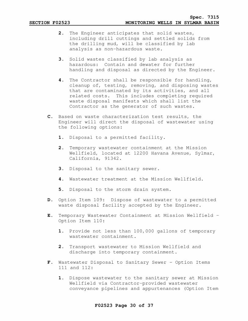
2. The Engineer anticipates that solid wastes, including drill cuttings and settled solids from the drilling mud, will be classified by lab analysis as non-hazardous waste.
3. Solid wastes classified by lab analysis as hazardous: Contain and dewater for further handling and disposal as directed by the Engineer.
4. The Contractor shall be responsible for handling, cleanup of, testing, removing, and disposing wastes that are contaminated by its activities, and all related costs. This includes completing required waste disposal manifests which shall list the Contractor as the generator of such wastes.
C. Based on waste characterization test results, the Engineer will direct the disposal of wastewater using the following options:
1. Disposal to a permitted facility.
2. Temporary wastewater containment at the Mission Wellfield, located at 12200 Havana Avenue, Sylmar, California, 91342.
3. Disposal to the sanitary sewer.
4. Wastewater treatment at the Mission Wellfield.
5. Disposal to the storm drain system.
D. Option Item 109: Dispose of wastewater to a permitted waste disposal facility accepted by the Engineer.
E. Temporary Wastewater Containment at Mission Wellfield - Option Item 110:
1. Provide not less than 100,000 gallons of temporary wastewater containment.
2. Transport wastewater to Mission Wellfield and discharge into temporary containment.
F. Wastewater Disposal to Sanitary Sewer - Option Items 111 and 112:
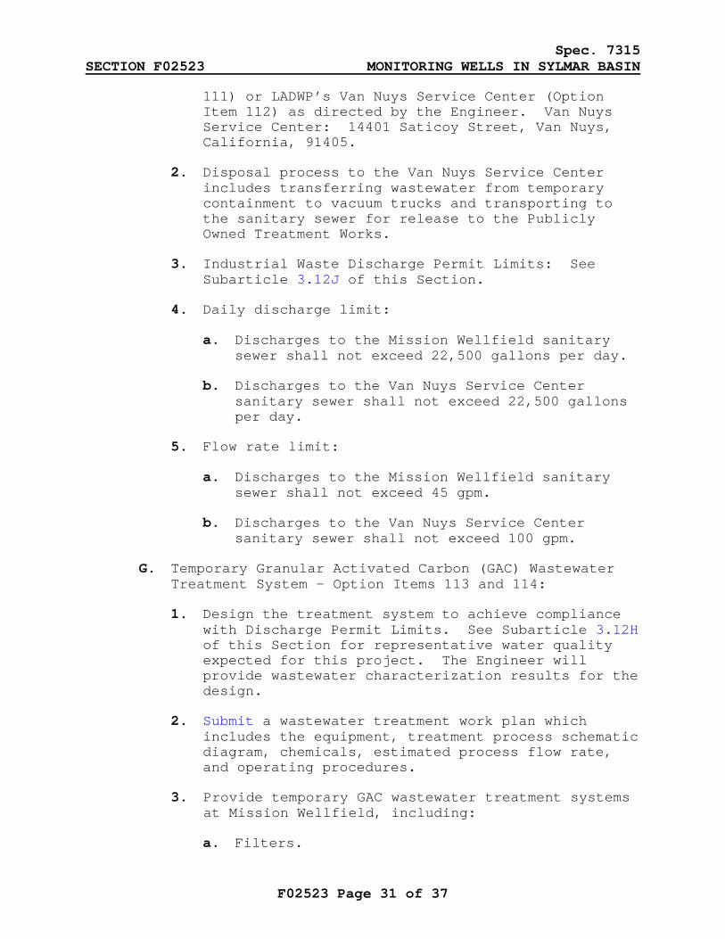
1. Dispose wastewater to the sanitary sewer at Mission Wellfield via Contractor-provided wastewater conveyance pipelines and appurtenances (Option Item
Spec. 7315 SECTION F02523 MONITORING WELLS IN SYLMAR BASIN
F02523 Page 31 of 37
111) or LADWP’s Van Nuys Service Center (Option Item 112) as directed by the Engineer. Van Nuys Service Center: 14401 Saticoy Street, Van Nuys, California, 91405.
2. Disposal process to the Van Nuys Service Center includes transferring wastewater from temporary containment to vacuum trucks and transporting to the sanitary sewer for release to the Publicly Owned Treatment Works.
3. Industrial Waste Discharge Permit Limits: See Subarticle 3.12J of this Section.
4. Daily discharge limit:
a. Discharges to the Mission Wellfield sanitary sewer shall not exceed 22,500 gallons per day.
b. Discharges to the Van Nuys Service Center sanitary sewer shall not exceed 22,500 gallons per day.
5. Flow rate limit:
a. Discharges to the Mission Wellfield sanitary sewer shall not exceed 45 gpm.
b. Discharges to the Van Nuys Service Center sanitary sewer shall not exceed 100 gpm.
G. Temporary Granular Activated Carbon (GAC) Wastewater Treatment System - Option Items 113 and 114:
1. Design the treatment system to achieve compliance with Discharge Permit Limits. See Subarticle 3.12H of this Section for representative water quality expected for this project. The Engineer will provide wastewater characterization results for the design.
2. Submit a wastewater treatment work plan which includes the equipment, treatment process schematic diagram, chemicals, estimated process flow rate, and operating procedures.
3. Provide temporary GAC wastewater treatment systems at Mission Wellfield, including:
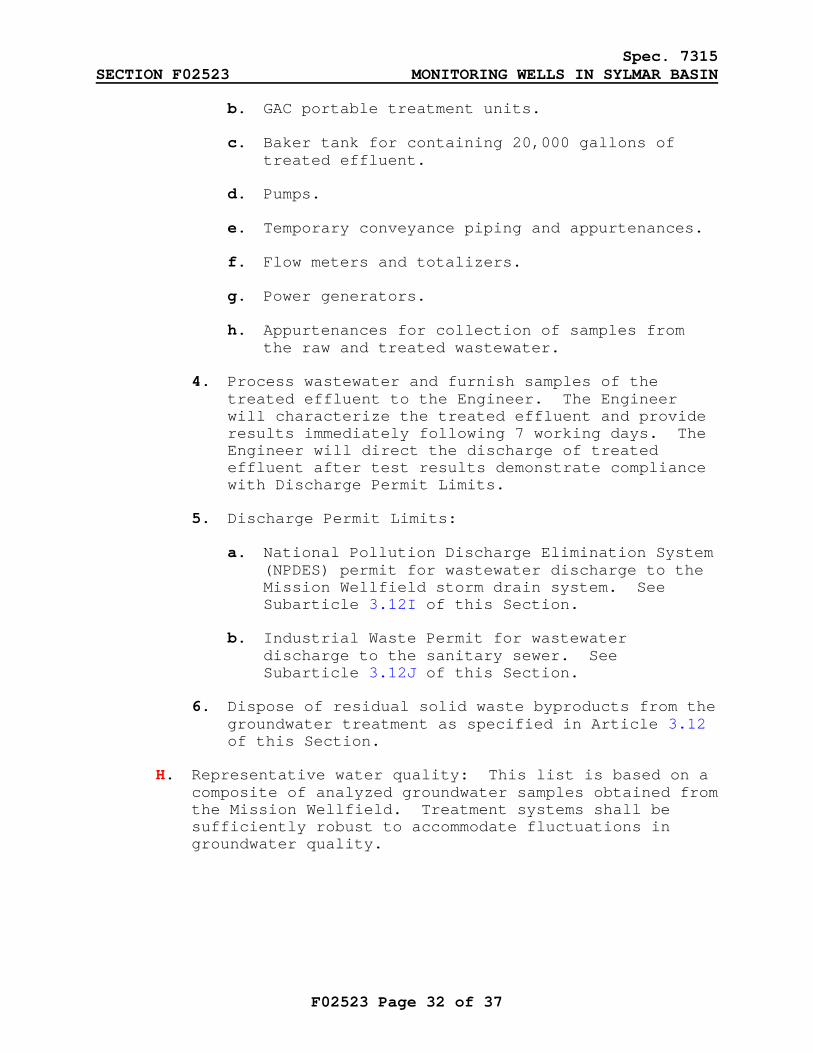
a. Filters.
Spec. 7315 SECTION F02523 MONITORING WELLS IN SYLMAR BASIN
F02523 Page 32 of 37
b. GAC portable treatment units.
c. Baker tank for containing 20,000 gallons of treated effluent.
d. Pumps.
e. Temporary conveyance piping and appurtenances.
f. Flow meters and totalizers.
g. Power generators.
h. Appurtenances for collection of samples from the raw and treated wastewater.
4. Process wastewater and furnish samples of the treated effluent to the Engineer. The Engineer will characterize the treated effluent and provide results immediately following 7 working days. The Engineer will direct the discharge of treated effluent after test results demonstrate compliance with Discharge Permit Limits.
5. Discharge Permit Limits:
a. National Pollution Discharge Elimination System (NPDES) permit for wastewater discharge to the Mission Wellfield storm drain system. See Subarticle 3.12I of this Section.
b. Industrial Waste Permit for wastewater discharge to the sanitary sewer. See Subarticle 3.12J of this Section.
6. Dispose of residual solid waste byproducts from the groundwater treatment as specified in Article 3.12 of this Section.
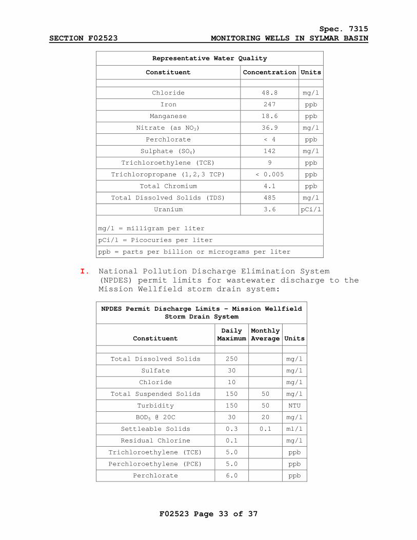
H. Representative water quality: This list is based on a composite of analyzed groundwater samples obtained from the Mission Wellfield. Treatment systems shall be sufficiently robust to accommodate fluctuations in groundwater quality.
Spec. 7315 SECTION F02523 MONITORING WELLS IN SYLMAR BASIN
F02523 Page 33 of 37
Representative Water Quality
Constituent Concentration Units
Chloride 48.8 mg/l
Iron 247 ppb
Manganese 18.6 ppb
Nitrate (as NO3) 36.9 mg/l
Perchlorate < 4 ppb
Sulphate (SO4) 142 mg/l
Trichloroethylene (TCE) 9 ppb
Trichloropropane (1,2,3 TCP) < 0.005 ppb
Total Chromium 4.1 ppb
Total Dissolved Solids (TDS) 485 mg/l
Uranium 3.6 pCi/l
mg/l = milligram per liter
pCi/l = Picocuries per liter
ppb = parts per billion or micrograms per liter
I. National Pollution Discharge Elimination System
(NPDES) permit limits for wastewater discharge to the Mission Wellfield storm drain system:
NPDES Permit Discharge Limits – Mission Wellfield Storm Drain System
Constituent
Daily Maximum
Monthly Average
Units
Total Dissolved Solids 250 mg/l
Sulfate 30 mg/l
Chloride 10 mg/l
Total Suspended Solids 150 50 mg/l
Turbidity 150 50 NTU
BOD5 @ 20C 30 20 mg/l
Settleable Solids 0.3 0.1 ml/l
Residual Chlorine 0.1 mg/l
Trichloroethylene (TCE) 5.0 ppb
Perchloroethylene (PCE) 5.0 ppb
Perchlorate 6.0 ppb
Spec. 7315 SECTION F02523 MONITORING WELLS IN SYLMAR BASIN
F02523 Page 34 of 37
NPDES Permit Discharge Limits – Mission Wellfield Storm Drain System
Constituent
Daily Maximum
Monthly Average
Units
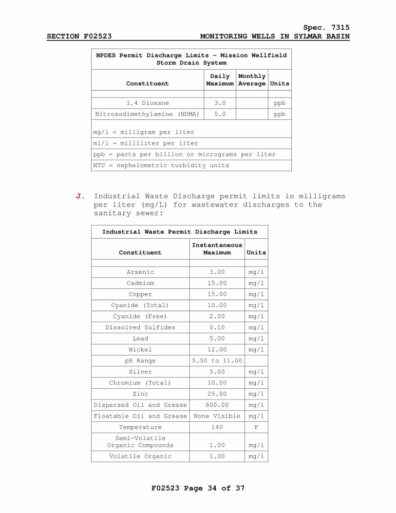
1,4 Dioxane 3.0 ppb
Nitrosodimethylamine (NDMA) 5.0 ppb
mg/l = milligram per liter
ml/l = milliliter per liter
ppb = parts per billion or micrograms per liter
NTU = nephelometric turbidity units
J. Industrial Waste Discharge permit limits in milligrams
per liter (mg/L) for wastewater discharges to the sanitary sewer:
Industrial Waste Permit Discharge Limits
Constituent
InstantaneousMaximum
Units
Arsenic 3.00 mg/l
Cadmium 15.00 mg/l
Copper 15.00 mg/l
Cyanide (Total) 10.00 mg/l
Cyanide (Free) 2.00 mg/l
Dissolved Sulfides 0.10 mg/l
Lead 5.00 mg/l
Nickel 12.00 mg/l
pH Range 5.50 to 11.00
Silver 5.00 mg/l
Chromium (Total) 10.00 mg/l
Zinc 25.00 mg/l
Dispersed Oil and Grease 600.00 mg/l
Floatable Oil and Grease None Visible mg/l
Temperature 140 F
Semi-Volatile Organic Compounds 1.00 mg/l
Volatile Organic 1.00 mg/l
Spec. 7315 SECTION F02523 MONITORING WELLS IN SYLMAR BASIN
F02523 Page 35 of 37
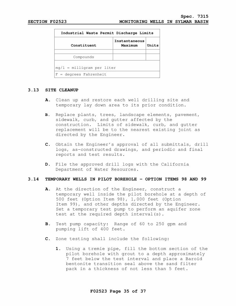
Industrial Waste Permit Discharge Limits
Constituent
InstantaneousMaximum
Units
Compounds
mg/l = milligram per liter
F = degrees Fahrenheit
3.13 SITE CLEANUP
A. Clean up and restore each well drilling site and temporary lay down area to its prior condition.
B. Replace plants, trees, landscape elements, pavement, sidewalk, curb, and gutter affected by the construction. Limits of sidewalk, curb, and gutter replacement will be to the nearest existing joint as directed by the Engineer.
C. Obtain the Engineer’s approval of all submittals, drill logs, as-constructed drawings, and periodic and final reports and test results.
D. File the approved drill logs with the California Department of Water Resources.
3.14 TEMPORARY WELLS IN PILOT BOREHOLE - OPTION ITEMS 98 AND 99
A. At the direction of the Engineer, construct a temporary well inside the pilot borehole at a depth of 500 feet (Option Item 98), 1,000 feet (Option Item 99), and other depths directed by the Engineer. Set a temporary test pump to perform an aquifer zone test at the required depth interval(s).
B. Test pump capacity: Range of 60 to 250 gpm and pumping lift of 400 feet.
C. Zone testing shall include the following:
1. Using a tremie pipe, fill the bottom section of the pilot borehole with grout to a depth approximately 7 feet below the test interval and place a Baroid bentonite transition seal above the sand filter pack in a thickness of not less than 5 feet.
Spec. 7315 SECTION F02523 MONITORING WELLS IN SYLMAR BASIN
F02523 Page 36 of 37
2. Lower a 20-foot perforated pipe section, attached to the bottom of the drill pipe string, into the borehole interval to be zone tested.
3. Place sand filter pack around the perforated section to a depth approximately 2 feet above and below the perforated pipe section and place a second Baroid Bentonite transition seal above the sand filter pack in a thickness of not less than 5 feet.
4. Pump the temporary well using air lift techniques for approximately 3 hours, followed by pumping using a submersible pump lowered into the drill pipe. Pump at a constant rate as directed by the Engineer for approximately 3 hours.
5. Measure and record the water level in the temporary well and the discharge flow rate. Measure pH, temperature, electrical conductivity, and turbidity at 15-minute intervals.
6. Provide a water quality sampling point as near as possible to the well head. As directed by the Engineer, reduce the pumping rate and facilitate the Engineer’s collection of water quality samples from the pump discharge.
7. Turn off the pump and measure water levels at regular intervals for 2 hours.
8. Provide a record of the well testing process in accordance with Section F01322.
D. At the completion of each test, raise the drill string and perforated pipe section to the subsequent test interval and construct an additional temporary well as directed by the Engineer.
3.15 AQUIFER PUMP TEST - OPTION ITEM 116
A. Set a temporary submersible pump and discharge piping within the 2-inch or 4-inch well casing as directed by the Engineer to conduct aquifer pump tests.
B. Test pump capacity: Range of 60 to 250 gpm and a pumping lift of 400 feet.
C. Conduct step-rate and constant-rate pump tests as directed by the Engineer.
Spec. 7315 SECTION F02523 MONITORING WELLS IN SYLMAR BASIN
F02523 Page 37 of 37
D. Duration: 40 hours, including mobilization, installation and removal of the temporary pump and discharge pipe, and demobilization.
E. Measure and record the water level in each well, pump discharge rate, totalizing flow, electrical conductivity, pH, temperature, and turbidity of the discharge on the following schedule:
1. First 10 minutes: Every minute.
2. 10 minutes to 120 minutes: Every 10 minutes.
3. 120 minutes to end of test: Every hour.
F. Remove accumulated sediment from the well after completing all pump tests.
END OF SECTION
ANSELMO G. COLLINS Acting Director of Supply Chain Services
Attachment 5 - LGA Application Work Plan Groundwater Monitoring Wells Installation Project – Sylmar Basin Los Angeles Department of Water and Power
7/12/2012
APPENDIX B
Example Sampling and Analysis Plan (SAP)
(without attachments)
Tujunga Monitoring Well Installation Sampling and Analysis Plan
City of Los Angeles, Los Angeles County, California
USACE Delivery Order Number: WP12P7-05-0049 Document Control Number: 20074.064.105.1220
May 20 2011
Prepared by:
Ben Castellana Weston Solutions, Inc.
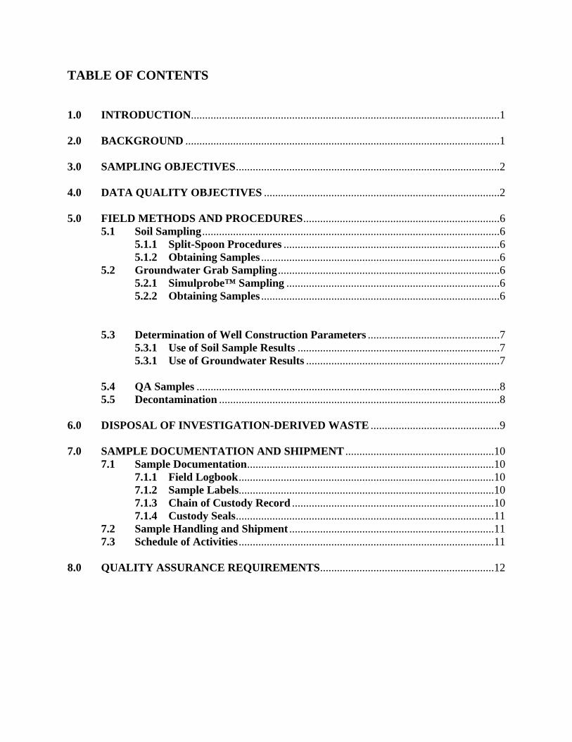
TABLE OF CONTENTS 1.0 INTRODUCTION..............................................................................................................1 2.0 BACKGROUND ................................................................................................................1 3.0 SAMPLING OBJECTIVES ..............................................................................................2 4.0 DATA QUALITY OBJECTIVES ....................................................................................2 5.0 FIELD METHODS AND PROCEDURES ......................................................................6
5.1 Soil Sampling ..........................................................................................................6 5.1.1 Split-Spoon Procedures .............................................................................6 5.1.2 Obtaining Samples .....................................................................................6
5.2 Groundwater Grab Sampling ...............................................................................6 5.2.1 Simulprobe™ Sampling ............................................................................6 5.2.2 Obtaining Samples .....................................................................................6
5.3 Determination of Well Construction Parameters ...............................................7 5.3.1 Use of Soil Sample Results ........................................................................7 5.3.1 Use of Groundwater Results .....................................................................7
5.4 QA Samples ............................................................................................................8 5.5 Decontamination ....................................................................................................8
6.0 DISPOSAL OF INVESTIGATION-DERIVED WASTE ..............................................9 7.0 SAMPLE DOCUMENTATION AND SHIPMENT .....................................................10
7.1 Sample Documentation ........................................................................................10 7.1.1 Field Logbook ...........................................................................................10 7.1.2 Sample Labels...........................................................................................10 7.1.3 Chain of Custody Record ........................................................................10 7.1.4 Custody Seals ............................................................................................11
7.2 Sample Handling and Shipment .........................................................................11 7.3 Schedule of Activities ...........................................................................................11
8.0 QUALITY ASSURANCE REQUIREMENTS..............................................................12

TABLES Table 3-1: Analyte List and Methods .......................................................................................3 Table 4-1: Request for Analytical Services ...............................................................................5
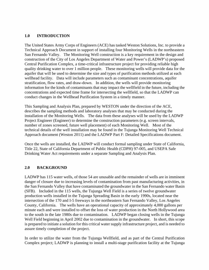
1.0 INTRODUCTION The United States Army Corps of Engineers (ACE) has tasked Weston Solutions, Inc. to provide a Technical Approach Document in support of installing four Monitoring Wells in the northeastern San Fernando Valley. The Monitoring Well construction is a key requirement in the design and construction of the City of Los Angeles Department of Water and Power’s (LADWP’s) proposed Central Purification Complex, a time-critical infrastructure project for providing reliable high quality drinking water to over 1 million people. These monitoring wells will provide data for the aquifer that will be used to determine the size and types of purification methods utilized at each wellhead facility. Data will include parameters such as contaminant concentrations, aquifer stratification, flow rates, and draw-down. In addition, the wells will provide monitoring information for the kinds of contaminants that may impact the wellfield in the future, including the concentrations and expected time frame for intersecting the wellfield, so that the LADWP can conduct changes in the Wellhead Purification System in a timely manner. This Sampling and Analysis Plan, prepared by WESTON under the direction of the ACE, describes the sampling methods and laboratory analyses that may be conducted during the installation of the Monitoring Wells. The data from these analyses will be used by the LADWP Project Engineer (Engineer) to determine the construction parameters (e.g. screen intervals, number of zones screened, future well placement) of each Monitoring Well. Most of the technical details of the well installation may be found in the Tujunga Monitoring Well Technical Approach document (Weston 2011) and the LADWP Part F: Detailed Specifications document. Once the wells are installed, the LADWP will conduct formal sampling under State of California, Title 22, State of California Department of Public Health (CDPH) 97-005, and USEPA Safe Drinking Water Act requirements under a separate Sampling and Analysis Plan. 2.0 BACKGROUND LADWP has 115 water wells, of those 54 are unusable and the remainder of wells are in imminent danger of closure due to increasing levels of contamination from past manufacturing activities, in the San Fernando Valley that have contaminated the groundwater in the San Fernando water Basin (SFB). Included in the 115 wells, the Tujunga Well Field is a series of twelve groundwater production wells installed in the Tujunga Spreading Basin in the early 1990s, located near the intersection of the 170 and I-5 freeways in the northeastern San Fernando Valley, Los Angeles County, California. The wells have an operational capacity of approximately 4,000 gallons per minute each and were installed to offset the loss of water production in the North Hollywood area to the south in the late 1980s due to contamination. LADWP began closing wells in the Tujunga Well Field beginning in April 2002 due to contamination in the groundwater. In short, this scope is prepared to initiate a solution for this critical water supply infrastructure project, and is needed to assure timely completion of the project. In order to utilize the water from the Tujunga Wellfield, and as part of the Central Purification Complex project; LADWP is planning to install a multi-stage purification facility at the Tujunga

2
and North Hollywood wellfields. This SAP only covers analyses conducted in support of the Monitoring Well Construction phase. Sampling conducted after the wells are completed will be conducted under a separate, more comprehensive plan.
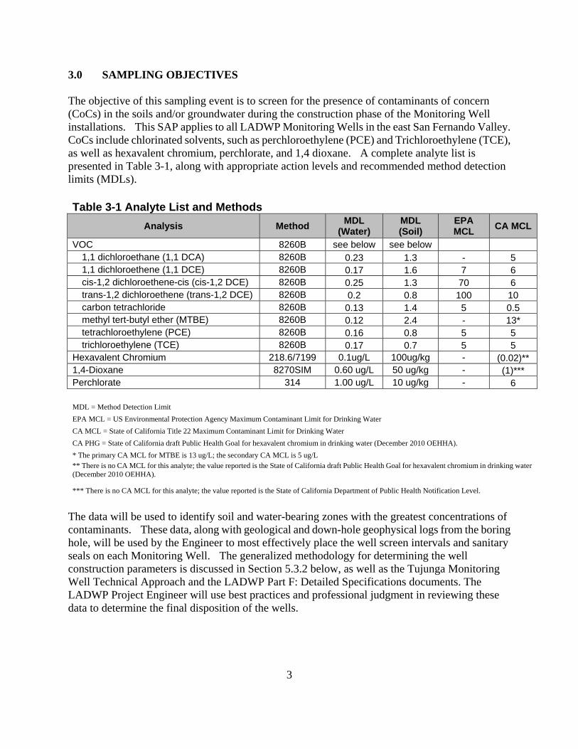
3
3.0 SAMPLING OBJECTIVES The objective of this sampling event is to screen for the presence of contaminants of concern (CoCs) in the soils and/or groundwater during the construction phase of the Monitoring Well installations. This SAP applies to all LADWP Monitoring Wells in the east San Fernando Valley. CoCs include chlorinated solvents, such as perchloroethylene (PCE) and Trichloroethylene (TCE), as well as hexavalent chromium, perchlorate, and 1,4 dioxane. A complete analyte list is presented in Table 3-1, along with appropriate action levels and recommended method detection limits (MDLs). Table 3-1 Analyte List and Methods
Analysis Method MDL
(Water) MDL (Soil)
EPA MCL
CA MCL
VOC 8260B see below see below 1,1 dichloroethane (1,1 DCA) 8260B 0.23 1.3 - 5 1,1 dichloroethene (1,1 DCE) 8260B 0.17 1.6 7 6 cis-1,2 dichloroethene-cis (cis-1,2 DCE) 8260B 0.25 1.3 70 6 trans-1,2 dichloroethene (trans-1,2 DCE) 8260B 0.2 0.8 100 10 carbon tetrachloride 8260B 0.13 1.4 5 0.5 methyl tert-butyl ether (MTBE) 8260B 0.12 2.4 - 13* tetrachloroethylene (PCE) 8260B 0.16 0.8 5 5 trichloroethylene (TCE) 8260B 0.17 0.7 5 5
Hexavalent Chromium 218.6/7199 0.1ug/L 100ug/kg - (0.02)** 1,4-Dioxane 8270SIM 0.60 ug/L 50 ug/kg - (1)*** Perchlorate 314 1.00 ug/L 10 ug/kg - 6
MDL = Method Detection Limit
EPA MCL = US Environmental Protection Agency Maximum Contaminant Limit for Drinking Water
CA MCL = State of California Title 22 Maximum Contaminant Limit for Drinking Water
CA PHG = State of California draft Public Health Goal for hexavalent chromium in drinking water (December 2010 OEHHA).
* The primary CA MCL for MTBE is 13 ug/L; the secondary CA MCL is 5 ug/L ** There is no CA MCL for this analyte; the value reported is the State of California draft Public Health Goal for hexavalent chromium in drinking water (December 2010 OEHHA).
*** There is no CA MCL for this analyte; the value reported is the State of California Department of Public Health Notification Level.
The data will be used to identify soil and water-bearing zones with the greatest concentrations of contaminants. These data, along with geological and down-hole geophysical logs from the boring hole, will be used by the Engineer to most effectively place the well screen intervals and sanitary seals on each Monitoring Well. The generalized methodology for determining the well construction parameters is discussed in Section 5.3.2 below, as well as the Tujunga Monitoring Well Technical Approach and the LADWP Part F: Detailed Specifications documents. The LADWP Project Engineer will use best practices and professional judgment in reviewing these data to determine the final disposition of the wells.
4
4.0 DATA QUALITY OBJECTIVES The Data Quality Objective (DQO) process, as set forth in the EPA document, Guidance for the Data Quality Objectives Process, EPA QA/G-4, was followed to establish the data quality objectives for this project. An outline of the process and the outputs for this project are included in Appendix A. This investigation will involve the generation of definitive data for soil and groundwater. The specific requirements for this data category are detailed in Section 9. The data generated under this project will comply with the requirements for that data category as defined in Data Quality Objective Process for Superfund, EPA 540/G-93/71, September 1993. All definitive analytical methods employed for this project will be methods approved by the EPA. For soil, the Engineer may choose to direct the driller to collect core samples in a manner consistent with EPA SOP #2012 in unsaturated soils to determine whether contamination from nearby sources has impacted the location. Action levels in soil will be the Method Detection Limit (MDL), as these CoCs are not naturally occurring at concentrations above the detection range. For groundwater, the Engineer may choose to collect grab samples when groundwater is first encountered, and at subsequent 50-foot intervals to establish a vertical contaminant profile. Samples will be analyzed for CoCs (see Table 3-1) by an LADWP laboratory (or its contract facility) with the most expedient turnaround time practicable. The highest priority analytes are TCE, PCE, and hexavalent chromium, with the remaining VOCs, perchlorate, and 1,4 dioxane being of secondary concern. The LADWP has determined that the action level should be the lower of Federal or State of California Maximum Contaminant Levels (MCL). The MDL should be at least half of the action level. Individual samples, QA samples, sample methods, sample containers, and preservatives are indicated in Table 4-1.
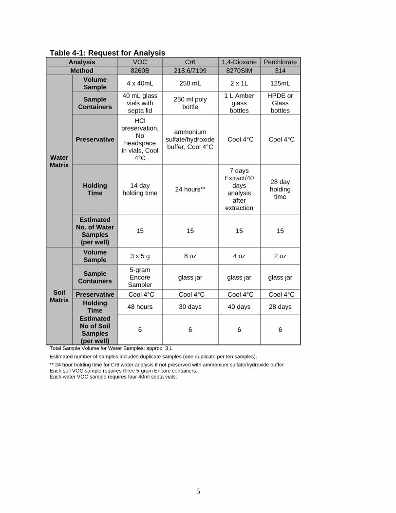
5
Table 4-1: Request for Analysis Analysis VOC Cr6 1,4-Dioxane Perchlorate Method 8260B 218.6/7199 8270SIM 314
Water Matrix
Volume Sample
4 x 40mL 250 mL 2 x 1L 125mL
Sample Containers
40 mL glass vials with septa lid
250 ml poly bottle
1 L Amber glass
bottles
HPDE or Glass bottles
Preservative
HCl preservation,
No headspace
in vials, Cool 4°C
ammonium sulfate/hydroxide buffer, Cool 4°C
Cool 4°C Cool 4°C
Holding Time
14 day holding time
24 hours**
7 days Extract/40
days analysis
after extraction
28 day holding
time
Estimated No. of Water
Samples (per well)
15 15 15 15
Soil Matrix
Volume Sample
3 x 5 g 8 oz 4 oz 2 oz
Sample Containers
5-gram Encore Sampler
glass jar glass jar glass jar
Preservative Cool 4°C Cool 4°C Cool 4°C Cool 4°C Holding
Time 48 hours 30 days 40 days 28 days
Estimated No of Soil Samples (per well)
6 6 6 6
Total Sample Volume for Water Samples: approx. 3 L
Estimated number of samples includes duplicate samples (one duplicate per ten samples).
** 24 hour holding time for Cr6 water analysis if not preserved with ammonium sulfate/hydroxide buffer Each soil VOC sample requires three 5-gram Encore containers. Each water VOC sample requires four 40ml septa vials.
6
5.0 FIELD METHODS AND PROCEDURES 5.1 Soil Sampling 5.1.1 Split-Spoon Sampling Procedures In conformance with ERT Soil Sampling Guidance (ERT SOP #2012), a clean, eighteen-inch split-spoon sample tube with brass sleeves will be advanced via the drill rig wire line through the conductor casing. Blow counts for each six-inch interval will be called off by the driller and the geologist will log these data. The split-spoon sample tube will be brought to the surface and opened for the geologist’s inspection. 5.1.2 Obtaining Samples Upon inspection, the geologist will collect three Encore™ sample containers at the interval specified by the Engineer. Samples should be biased toward finer-grained lithologies, should any stratification be present. The samples will be capped, labeled, and immediately placed on ice. An additional four-ounce volume will be collected for dry weight calculation. Once the sample has been preserved, the geologist may log the remaining core. Sample container and preservative requirements are presented in Table 4-1. Upon preservation and storage of the samples, information for each sample will be recorded in the logbook and on a chain of custody form. 5.2 Groundwater Sampling 5.2.1 Simulprobe™ Procedures Groundwater grab samples will be collected in accordance with Superfund Groundwater Sampling Guidance (EPA 542-S-02-001) and Simulprobe™ standard operating procedures. A nitrogen-charged Simulprobe™ sampler is lowered into the conductor casing to the appropriate depth using the drill rig wire line. The sampler is hammered into the bottom of the borehole, below the drill bit. The upper sheath pulls back as the sampler is driven into the strata. The sampler is pulled back four inches to expose the screen at the base of the core sample. The nitrogen atmosphere is evacuated via surface controller; the nitrogen in the sampler is replaced by groundwater, which flows into the sample canister. The sampler is re-charged with nitrogen and pulled to the surface. 5.2.2 Obtaining Samples Pre-preserved sample bottles will be filled from the Simulprobe™ sampler. The VOC sample bottles will be filled first, followed by the hexavalent chromium samples, followed by the perchlorate samples. Samples for 1,4 dioxane analyses will be collected last, and the Engineer may decide not to collect the 1,4 dioxane samples if time/sample volumes are not sufficient. The bottles will be labeled and placed on ice. Sample bottle and preservative requirements are presented in Table 4-1 as well as the analytical holding times. Upon preservation and storage of the samples, information for each sample will be recorded in the logbook and on a chain of custody form. The samples will be handed off to an LADWP courier, who will deliver the samples to the laboratory as soon as practicable (on the same day as sample collection). The samples will be analyzed with a 24-hour turnaround time.
7
5.3 Determination of Well Construction Parameters The Engineer will use the data collected under this SAP to determine the well construction parameters. The well construction parameters may include:
• Completing the well in one, two, or three water-bearing zones. • The depth of each zone screened. • The thickness of the sanitary seal. • Whether the boring should be abandoned, and the well constructed at another location.
The determination of these factors will be based in part on chemical data collected under this SAP, as well as geologic and geophysical data collected during the Pilot Boring phase. The overall end-use of these data is described in Tujunga Monitoring Well Technical Approach document (Weston 2011) and the LADWP Part F: Detailed Specifications documents. Specific data use objectives are outlined below, as well as in Appendix A: Data Quality Objectives. 5.3.1 Use of Soil Analyses Results The use of soil data for this stage of the well construction is laid out in Appendix A: Data Quality Objective No. 1. Soil analyses will be used primarily to determine whether COCs are present in the soils through which the well is constructed. The presence of COCs in the soil column may cause the Engineer to consider installing a sanitary seal through the contaminated zone in order to ensure that the annular space does not become a conduit for contaminants to groundwater. In addition, these data may be useful in the on-going investigation into the source area for the groundwater pollution problem in the area. 5.3.2 Use of Groundwater Results The use of groundwater data for this stage of the well construction is laid out in Appendix A: Data Quality Objective No. 2. Groundwater analytical data will be collected at regular intervals through the water-bearing zone to determine concentrations of COCs at these intervals. The data will be plotted along with the geologic log so that the Engineer may make determinations about whether the contractor should continue drilling the Pilot Boring to the design depth, cease drilling and install the well in a shallow configuration, or drill deeper to investigate conditions at depths greater than the initial design depth. One example of where the Engineer may choose to cease drilling and install the well in shallow groundwater would be in a situation where either COCs are not detected in the water column, or COCs are detected in shallow water, but concentrations dissipate to non-detect levels with depth. One example of where the Engineer might chose to drill deeper than the design depth would be where COCs are detected at increasing concentrations in the deepest levels of the design depth. Once the Pilot Boring is drilled to total depth, the field team will conduct a geophysical survey of the borehole to assist with determining where the highest zones of hydrologic conductivity occur. The geophysical survey may include:
• Long and Short normal resistivity. • Point Resistivity
8
• Guard log • Natural Gamma • Spectral Gamma • Spontaneous Potential • Sonic • Directional Drilling • Caliper Surveys
The Engineer may choose to conduct one or a number of geophysical tests to assist with installing the well screen(s) at the appropriate depth. The well screen should be installed in lithologies that exhibit medium- to coarse-grain clasts that will not infiltrate the sand pack or well screen slot width. The well should not be screened across any clay, silt, or fine sand that might infiltrate and cause degradation of water quality. 5.4 QA Samples One blind duplicate sample will be collected per matrix for every ten field samples collected. Duplicate samples will have a unique sample name and will be collected as a distinct sample. The corresponding field sample will be recorded in the logbook, but not reported to the laboratory. One matrix spike/mean spike duplicate (MS/MSD) sample per matrix will be submitted for every twenty (20) field samples. A Matrix Spike and Spike Duplicate (MS/MSD) sample is a representative, but randomly chosen sample that has known concentrations of analytes of interest added to the samples prior to sample preparation and analysis. They are processed along with the same un-spiked sample. The purpose of the MS/MSD is to document the accuracy and precision of the method for that specific sample. The MS/MSD sample will require additional volume, but will have the same sample name as the field sample. The MS/MSD designation will be reported to the laboratory. A trip blank will be included with any sample delivery that includes samples from multiple zones. The trip blank will consist of an appropriate number of sample bottles filled with distilled or laboratory-grade water. The trip blanks will be given a sample name in the sequence “Well Number”-“Trip”-“Date,” such that a trip blank prepared to accompany a set of samples from TJ-MW-08 on August 12, 2011 will have the name, “TJ-MW-08-TRIP-8-12-2011.” The trip blank will be analyzed for all CoCs, and the data will be used as a measure of cross contamination during shipping. Although trip blanks are not necessary when only one sample is shipped, the Engineer may choose to include a trip blank as an overall sampling method blank. No equipment blank will be collected as only dedicated equipment will be used. 5.5 Decontamination Dedicated equipment will be used during water sampling; therefore, no decontamination will be required.
9
6.0 DISPOSAL OF INVESTIGATION-DERIVED WASTE Used gloves and sample canisters will be double-bagged and disposed of as municipal waste. Soil waste will be co-mingled with drill cuttings in roll-off bins, which will be profiled and properly disposed of based on the profile data. Purge water will be drummed and stored in the yard area pending waste profiling. This water may be co-mingled with well development water produced by the same well. No other investigation-derived waste is anticipated.
10
7.0 SAMPLE DOCUMENTATION AND SHIPMENT 7.1 Sample Documentation All sample documents will be completed legibly, in ink. Any corrections or revisions will be made by lining through the incorrect entry and by initialing the error. 7.1.1 Field Logbook The field logbook is essentially a descriptive notebook detailing site activities and observations so that an accurate account of field procedures can be reconstructed in the writer's absence. All entries will be dated and signed by the individuals making the entries, and will include the following: 1. Site name and project number. 2. Names of personnel on site. 3. Dates and times of all entries in military time. 4. Descriptions of all site activities, including site entry and exit times. 5. Site events and discussions. 6. Weather conditions. 7. Site observations. 8. Identification and description of samples and locations. 9. Date and time of sample collections, along with chain of custody information. 10. Record of photographs. 11. Site sketches. 7.1.2 Sample Labels Sample labels will clearly identify the particular sample, and will include the following: 1. Site name. 2. Time and date sample was taken. 3. Sample identification number. 4. Sample preservation. 5. Analysis requested. Sample labels will be securely affixed to the sample container. 7.1.3 Chain of Custody Record A Chain of Custody record will be maintained from the time the sample is taken to its final deposition. Every transfer of custody must be noted and signed for, and a copy of this record kept by each individual who has signed. When samples are not under direct control of the individual responsible for them, they must be stored in a container sealed with a Custody Seal.
11
The Chain of Custody record should include (at minimum) the following: 1. Sample identification number. 2. Sample matrix. 3. Sample location. 4. Sample date and time. 5. Names(s) and signature(s) of sampler(s). 6. Signature(s) of any individual(s) with control over samples. 7. Analysis type required. 8. Data package requirements. 9. Project account number. 10. Name, address, and phone number of the individual designated to receive results, data
package, and invoice. 7.1.4 Custody Seals Custody Seals demonstrate that a sample container has not been tampered with, or opened. The individual in possession of the samples will sign and date the seal, affixing it in such a manner that the container cannot be opened without breaking the seal. The name of this individual, along with a description of the sample packaging, will be noted in the field book. 7.2 Sample Handling and Shipment Samples will be placed in a sturdy cooler with hard plastic inside. The following packaging procedures will be followed: 1. Secure the drain plug of the cooler with tape to prevent melting ice from leaking out of the
cooler; 2. Line the bottom of the cooler with bubble wrap to prevent breakage during shipment; 3. Check screw caps for tightness 4. Secure bottle/container tops with tape and custody seal all container tops; 5. Affix sample labels onto the containers with clear tape; 6. Place VOA’s in a foam holder to prevent breakage; and 7. Seal all sample containers in heavy-duty plastic bags. Samples will be handed over to an LADWP courier who will deliver the samples to the LADWP laboratory for analyses. 7.3 Schedule of Activities Samples will be collected during the Pilot Boring phase of Monitoring Well installation. It is currently anticipated that the first four of these wells will be installed between May 1, 2011, and January 31, 2012. Additional wells are expected to be installed over the next two to three years. Upon mobilization to each drill site, the contractor will present a Pilot Boring schedule to the Engineer, who will then decide whether samples will be collected. The contractor will notify the Engineer at least 24 hours before sampling occurs, including the total number and matrices of samples to be collected and the approximate time samples will be collected.
12
The laboratory will conduct the analyses on an as-soon-as-possible schedule, because the Engineer may use these data to revise the drilling schedule. 8.0 QUALITY ASSURANCE REQUIREMENTS 8.1 Analytical and Data Package Requirements It is required that all samples be analyzed in accordance with the methods listed in Tables 3-1 and 4-1. The laboratory is required to supply documentation to demonstrate that their data meet the requirements specified in the EPA Method. The data validation package shall include copies of all original documentation generated in support of this project. In addition, the laboratory will provide original documentation to support that all requirements of the methods have been met. This includes, but is not limited to, sample tags, custody records, shipping information, sample preparation/extraction records, and instrument printouts such as mass spectra. Original documentation will be retained by the LADWP; copies of the documentation required can be made available on request. 8.2 Data Validation Data validation of analytical data generated by the LADWP will be conducted in accordance with the EPA Region 9 Superfund Data Evaluation/Validation Guidance R9QA/006.1 (EPA 2001). Data validation will be conducted by the LADWP either by an independent contractor or a qualified LADWP laboratory manager. Tier 3 Validation for up to 100% of the data will be required, based on the LADWP Engineer’s cursory review of the data. Baring the engineer’s finding any significant issues with the data, a 10% validation will suffice. To meet requirements for categorization as definitive data, the following criteria will be evaluated: Holding times Sampling design approach Blank contamination Initial and continuing calibration Detection limits Analyte identification and quantitation Matrix spike recoveries Performance evaluation samples when specified Analytical and total error determination Laboratory Control Samples. Upon completion of validation, data will be classified as one of the following: acceptable for use without qualifications, acceptable for use with qualifications, or unacceptable for use.