atlas placement and alignments
DESCRIPTION
ATLAS Placement and Alignments. David Lissauer / BNL. Experimental Hall is very small compare to ATLAS Size. “Ship in a Bottle” Need to be aligned to the beam line to ~ mm and many of large Many envelopes have less than 20mm stay clear areasbetween moving Objects. Every Silly mm Counts!!!. - PowerPoint PPT PresentationTRANSCRIPT
D. Lissauer – Alignment and Placements Overview – ATLAS Overview Week – October 7 ’04.1
ATLAS Placement and ATLAS Placement and AlignmentsAlignments
David Lissauer / BNL
Result of many discussions over the past year with:
Survey Team. LHC Machine and Civil Engineering. Toroid and Muon Placement. Calorimeters: LAr/Tile.Inner Detector. Beam Pipe.EC Toroid, ShieldingPhysics.
Experimental Hall is very small compare to ATLAS Size.
“Ship in a Bottle”
Need to be aligned to the beam line to ~ mm and many of large Many envelopes have less than 20mm stay clear areasbetween
moving Objects.
Every Silly mm Counts!!!
D. Lissauer – Alignment and Placements Overview – ATLAS Overview Week – October 7 ’04.2
ATLAS Placement ATLAS Placement ConsiderationsConsiderations
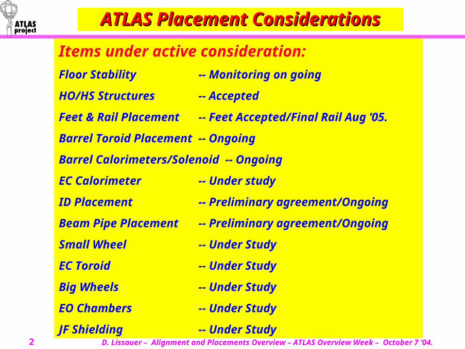
Items under active consideration:
Floor Stability -- Monitoring on going
HO/HS Structures -- Accepted
Feet & Rail Placement -- Feet Accepted/Final Rail Aug ’05.
Barrel Toroid Placement -- Ongoing
Barrel Calorimeters/Solenoid -- Ongoing
EC Calorimeter -- Under study
ID Placement -- Preliminary agreement/Ongoing
Beam Pipe Placement -- Preliminary agreement/Ongoing
Small Wheel -- Under Study
EC Toroid -- Under Study
Big Wheels -- Under Study
EO Chambers -- Under Study
JF Shielding -- Under Study
D. Lissauer – Alignment and Placements Overview – ATLAS Overview Week – October 7 ’04.3
LHC Nominal Beam and IP.LHC Nominal Beam and IP. Nominal Beam Line:Nominal Beam Line:
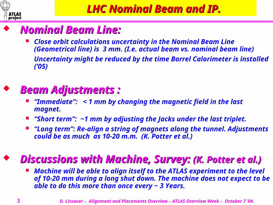
Close orbit calculations uncertainty in the Nominal Beam Line (Geometrical line) is 3 mm. (I.e. actual beam vs. nominal beam line)
Uncertainty might be reduced by the time Barrel Calorimeter is installed (’05)
Beam Adjustments :Beam Adjustments : “Immediate”: < 1 mm by changing the magnetic field in the last
magnet. “Short term”: ~1 mm by adjusting the Jacks under the last triplet. “Long term”: Re-align a string of magnets along the tunnel. Adjustments
could be as much as 10-20 m.m. (K. Potter et al.)
Discussions with Machine, Survey: Discussions with Machine, Survey: (K. Potter et al.)(K. Potter et al.) Machine will be able to align itself to the ATLAS experiment to the level
of 10-20 mm during a long shut down. The machine does not expect to be able to do this more than once every ~ 3 Years.
D. Lissauer – Alignment and Placements Overview – ATLAS Overview Week – October 7 ’04.4
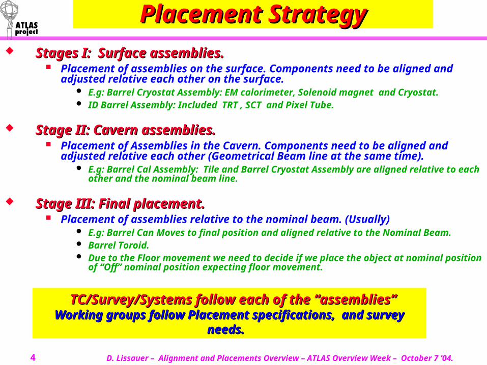
Placement StrategyPlacement Strategy Stages I: Surface assemblies.Stages I: Surface assemblies.
Placement of assemblies on the surface. Components need to be aligned and adjusted relative each other on the surface.
E.g: Barrel Cryostat Assembly: EM calorimeter, Solenoid magnet and Cryostat. ID Barrel Assembly: Included TRT , SCT and Pixel Tube.
Stage II: Cavern assemblies.Stage II: Cavern assemblies. Placement of Assemblies in the Cavern. Components need to be aligned and
adjusted relative each other (Geometrical Beam line at the same time). E.g: Barrel Cal Assembly: Tile and Barrel Cryostat Assembly are aligned relative to
each other and the nominal beam line.
Stage III: Final placement.Stage III: Final placement. Placement of assemblies relative to the nominal beam. (Usually)
E.g: Barrel Can Moves to final position and aligned relative to the Nominal Beam. Barrel Toroid. Due to the Floor movement we need to decide if we place the object at nominal
position of “Off” nominal position expecting floor movement.
TC/Survey/Systems follow each of the “assemblies”TC/Survey/Systems follow each of the “assemblies”Working groups follow Placement specifications, and survey Working groups follow Placement specifications, and survey
needs.needs.
D. Lissauer – Alignment and Placements Overview – ATLAS Overview Week – October 7 ’04.5
ATLAS Exp. Hall – Floor Movement ATLAS Exp. Hall – Floor Movement
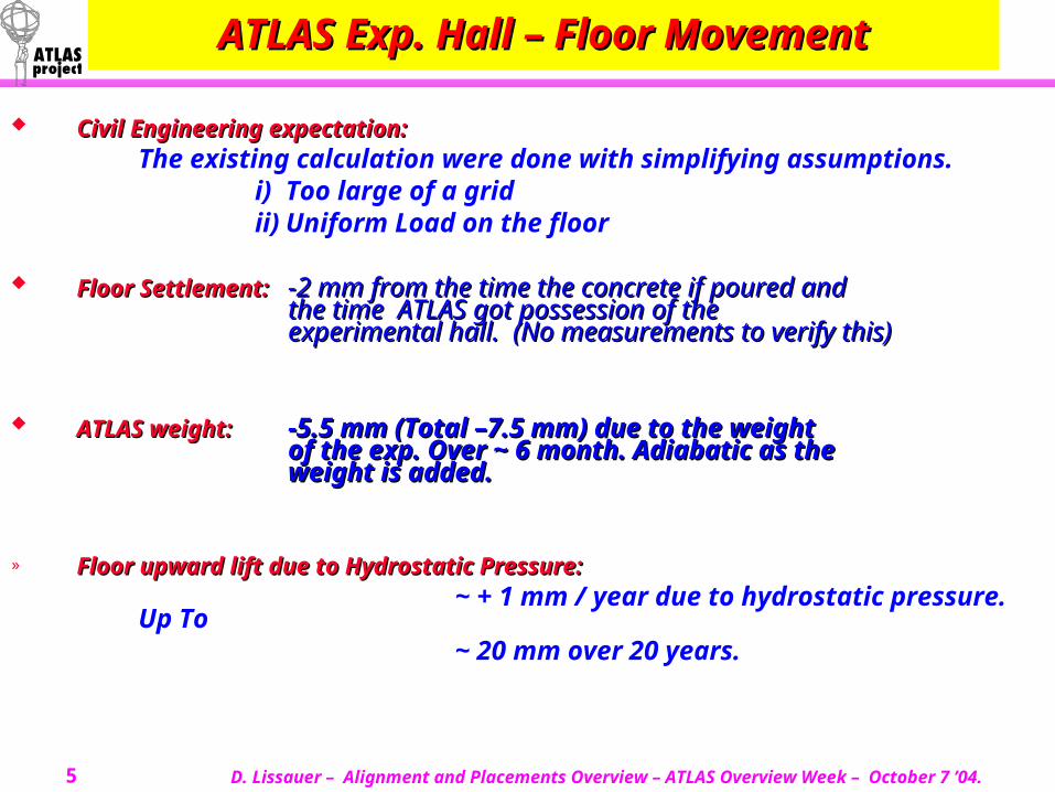
Civil Engineering expectation:Civil Engineering expectation:The existing calculation were done with simplifying assumptions.
i) Too large of a gridii) Uniform Load on the floor
Floor Settlement:Floor Settlement: -2 mm from the time the concrete if poured and -2 mm from the time the concrete if poured and the time ATLAS got possession of the the time ATLAS got possession of the experimental hall. (No measurements to verify this)experimental hall. (No measurements to verify this)
ATLAS weight:ATLAS weight: -5.5 mm (Total –7.5 mm) due to the weight -5.5 mm (Total –7.5 mm) due to the weight of the exp. Over ~ 6 month. Adiabatic as the of the exp. Over ~ 6 month. Adiabatic as the weight is added.weight is added.
» Floor upward lift due to Hydrostatic Pressure:Floor upward lift due to Hydrostatic Pressure:~ + 1 mm / year due to hydrostatic pressure.
Up To ~ 20 mm over 20 years.
D. Lissauer – Alignment and Placements Overview – ATLAS Overview Week – October 7 ’04.6
GRID Monitoring Floor GRID Monitoring Floor Movement Movement
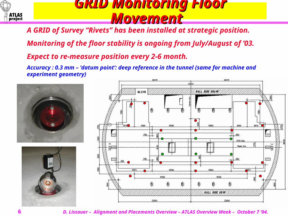
A GRID of Survey “Rivets” has been installed at strategic position.
Monitoring of the floor stability is ongoing from July/August of ’03.
Expect to re-measure position every 2-6 month.
Accuracy : 0.3 mm – ‘datum point’: deep reference in the tunnel (same for machine and experiment geometry)
D. Lissauer – Alignment and Placements Overview – ATLAS Overview Week – October 7 ’04.7
Hydrostatic Monitoring Hydrostatic Monitoring
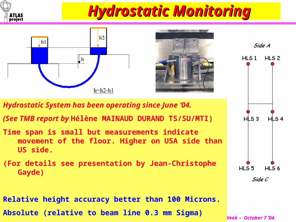
Hydrostatic System has been operating since June ’04.
(See TMB report by Hélène MAINAUD DURAND TS/SU/MTI)
Time span is small but measurements indicate movement of the floor. Higher on USA side than US side.
(For details see presentation by Jean-Christophe Gayde)
Relative height accuracy better than 100 Microns.
Absolute (relative to beam line 0.3 mm Sigma)
D. Lissauer – Alignment and Placements Overview – ATLAS Overview Week – October 7 ’04.8
Hydrostatic data qualityHydrostatic data quality
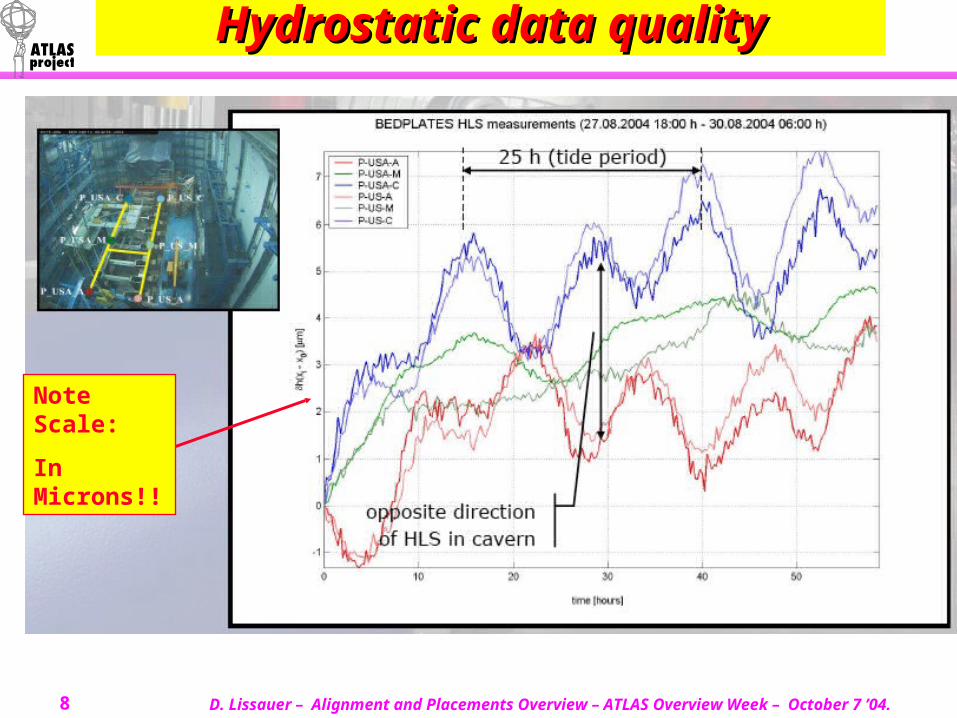
Note Scale:
In Microns!!
D. Lissauer – Alignment and Placements Overview – ATLAS Overview Week – October 7 ’04.9
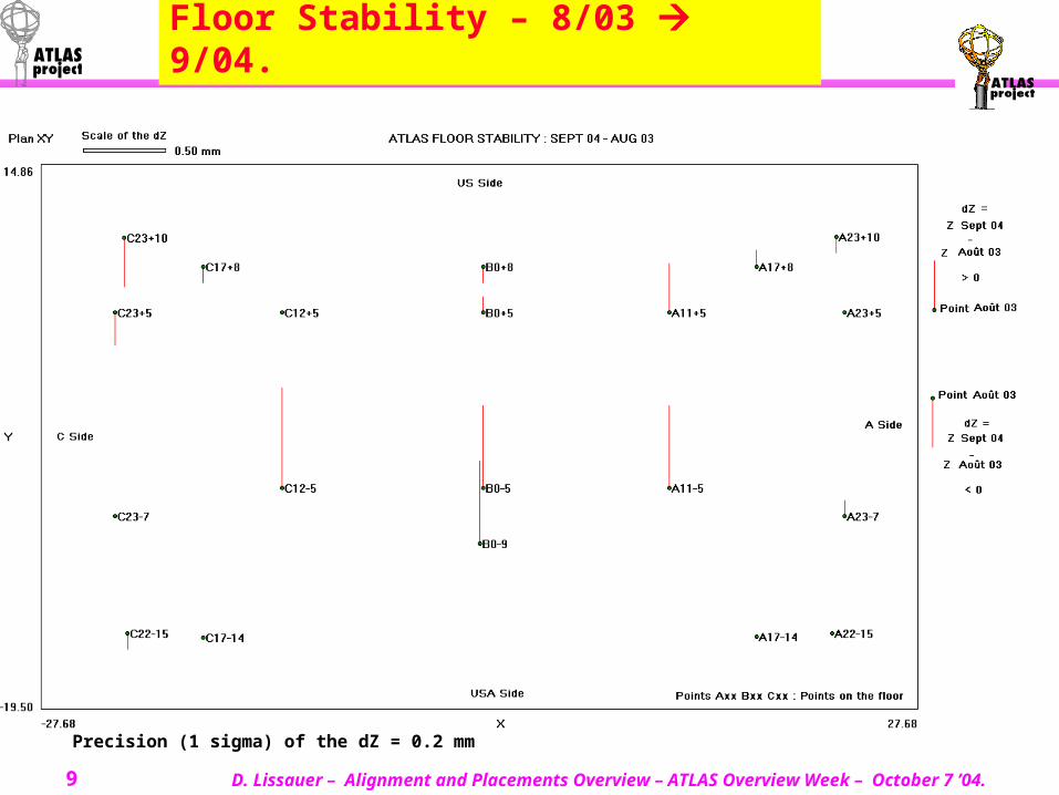
Floor Stability – 8/03 9/04.
Precision (1 sigma) of the dZ = 0.2 mm
D. Lissauer – Alignment and Placements Overview – ATLAS Overview Week – October 7 ’04.10
-20 -15 -10 -5 0 5 10 15 20
-10
-5
0
5
10
A23+5
A23-7
A17+8
A17-14
A11+5
A11-5
B0-9
B0-5
B0+5
B0+8
C12-5
C12+5
C17+8
C17-14
C23-7
C23+5
C23+10
C22-15
A23+10
A22-15 -0.6
-0.5
-0.4
-0.3
-0.2
-0.1
0
0.1
0.2
0.3
0.4
0.5
0.6
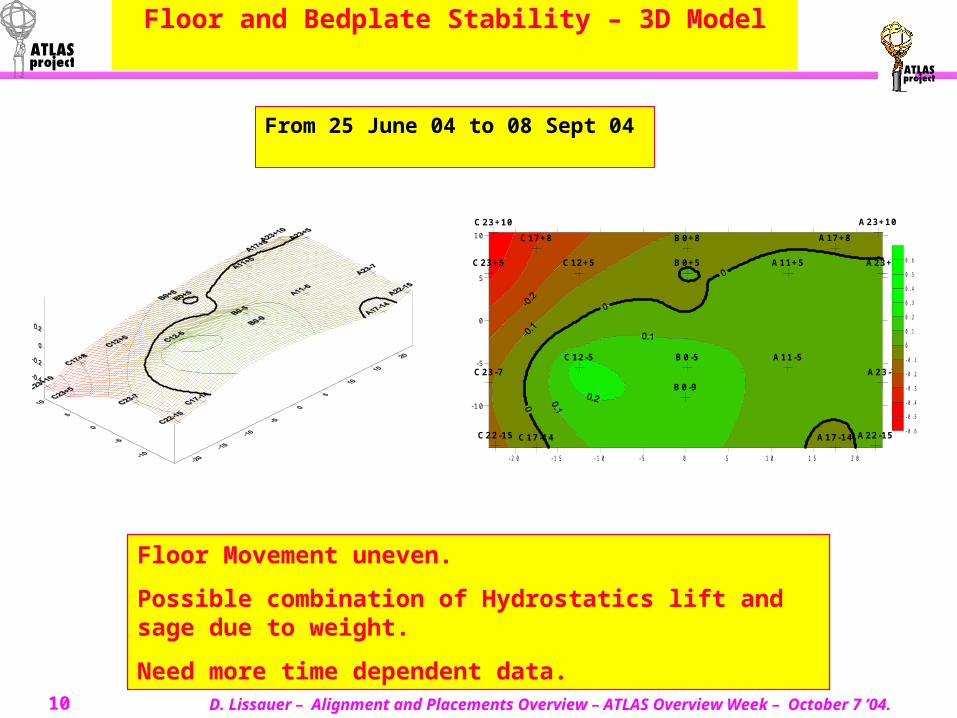
From 25 June 04 to 08 Sept 04
Floor and Bedplate Stability – 3D Model
Floor Movement uneven.
Possible combination of Hydrostatics lift and sage due to weight.
Need more time dependent data.
D. Lissauer – Alignment and Placements Overview – ATLAS Overview Week – October 7 ’04.11
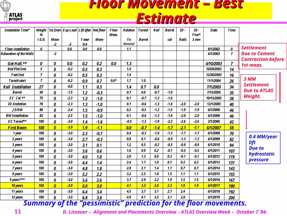
Floor Movement – Best Floor Movement – Best EstimateEstimate
Summary of the “pessimistic” prediction for the floor movements.
SettlementDue to Cement Contraction before1st meas.
3 MMSettlementDue to ATLASWeight.
0.4 MM/yearliftDue to hydrostaticpressure
Weight %
1st 2mm Exp Load Lift after Net floor Floor Meas.
Relative Toroid- Barrel ID - ID- Fine*
(-5.5) Move 1 year Move To Barrel cal Rails 3 mm-2 -3 0.4 Nominal
Floor installation 0 0.0 0.0 0.0 1.1 9/1/2002 0Relaxation of the Walls -2 4/1/2003 7
Get Hall.** 0 0 0.0 0.2 0.2 0.0 1.3 4/10/2003 7Bed Plat Inst. 5 0 -0.2 0.5 0.3 1.4 10/20/2003 14
Feet Inst 7 0 -0.2 0.5 0.3 1.4 12/30/2003 16Toroid-start 7 0 -0.2 0.9 0.7 0.6* 1.7 1.0 11/1/2004 26
Rail Installation 27 0 -0.8 1.1 0.3 1.4 0.7 0.0 7/1/2005 34Barrel 50 0 -1.5 1.2 -0.3 0.7 0.0 -0.7 -1.0 7/15/2005 35
EC Cal ** 75 0 -2.3 1.3 -1.0 0.1 -0.7 -1.3 -1.6 10/15/2005 38ID Instlation 76 0 -2.3 1.3 -1.0 0.1 -0.6 -1.3 -1.6 -2.0 -2.0 12/1/2005 40
JD/SW 80 0 -2.4 1.5 -0.9 0.2 -0.5 -1.2 -1.5 -1.9 -1.9 6/1/2006 46BW Installation 83 0 -2.5 1.5 -1.0 0.1 -0.6 -1.3 -1.6 -2.0 -2.0 6/1/2006 46
EC Toroid** 100 0 -3.0 1.4 -1.6 -0.5 -1.3 -1.9 -2.2 -2.6 -2.6 3/1/2006 43First Beam 100 0 -3.0 1.9 -1.1 0.0 -0.7 -1.4 -1.7 -2.1 -2.1 6/1/2007 58
1 year 100 0 -3.0 2.3 -0.7 0.4 -0.3 -1.0 -1.3 -1.7 -1.7 6/1/2008 702 years 100 0 -3.0 2.7 -0.3 0.8 0.1 -0.6 -0.9 -1.3 -1.3 6/1/2009 823 years 100 0 -3.0 3.1 0.1 1.2 0.5 -0.2 -0.5 -0.9 -0.9 6/1/2010 944 years 100 0 -3.0 3.6 0.6 1.6 0.9 0.2 -0.1 -0.5 -0.5 6/1/2011 1075 years 100 0 -3.0 4.0 1.0 2.0 1.3 0.6 0.3 -0.1 -0.1 6/1/2012 1196 years 100 0 -3.0 4.4 1.4 2.4 1.7 1.0 0.7 0.3 0.3 6/1/2013 1317 years 100 0 -3.0 4.8 1.8 2.8 2.1 1.4 1.1 0.7 0.7 6/1/2014 1438 years 100 0 -3.0 5.2 2.2 3.2 2.5 1.8 1.5 1.1 1.1 6/1/2015 155
9 years*** 100 0 -3.0 5.6 2.6 3.7 2.9 2.2 1.9 1.5 1.5 6/1/2016 16710 years 100 0 -3.0 6.0 3.0 4.1 3.3 2.6 2.3 1.9 1.9 6/1/2017 18011 years 100 0 -3.0 6.4 3.4 4.5 3.7 3.1 2.7 2.4 6/1/2018 19212 yeasr 100 0 -3.0 6.8 3.8 4.9 4.1 3.5 3.1 2.8 6/1/2019 204
Instalation Time* Rail Date Time
D. Lissauer – Alignment and Placements Overview – ATLAS Overview Week – October 7 ’04.12
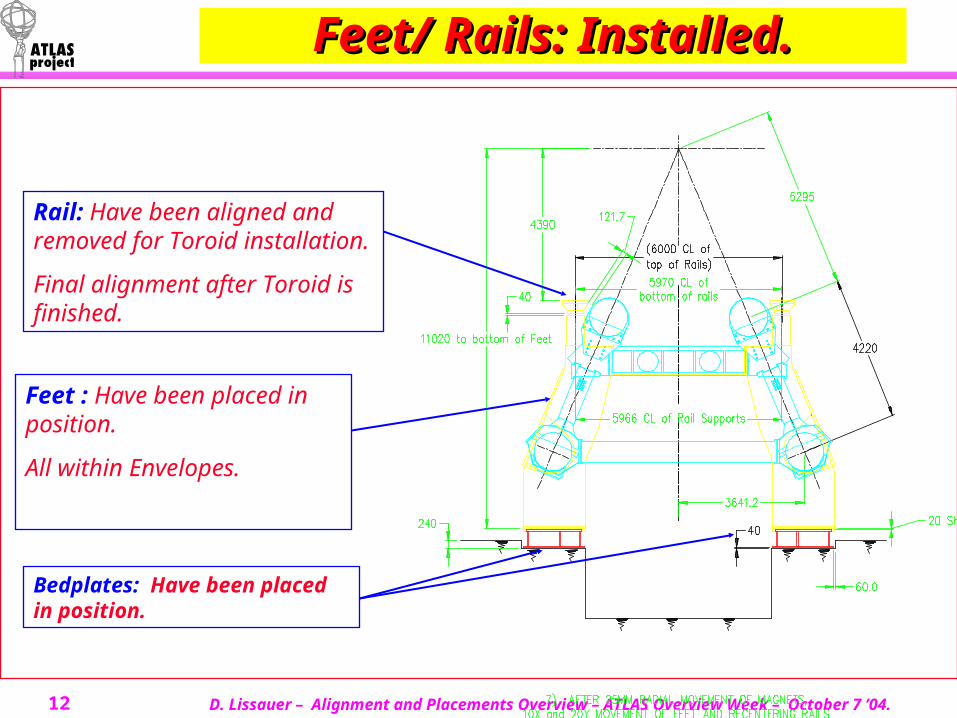
Feet/ Rails: Installed.Feet/ Rails: Installed.
Bedplates: Have been placed in position.
Feet : Have been placed in position.
All within Envelopes.
Rail: Have been aligned and removed for Toroid installation.
Final alignment after Toroid is finished.
D. Lissauer – Alignment and Placements Overview – ATLAS Overview Week – October 7 ’04.13
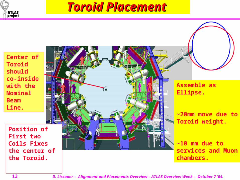
Toroid Placement Toroid Placement
Center of Toroid should co-inside with the Nominal Beam Line.
Position of First two Coils Fixes the center of the Toroid.
Assemble as Ellipse.
~20mm move due to Toroid weight.
~10 mm due to services and Muon chambers.
D. Lissauer – Alignment and Placements Overview – ATLAS Overview Week – October 7 ’04.14
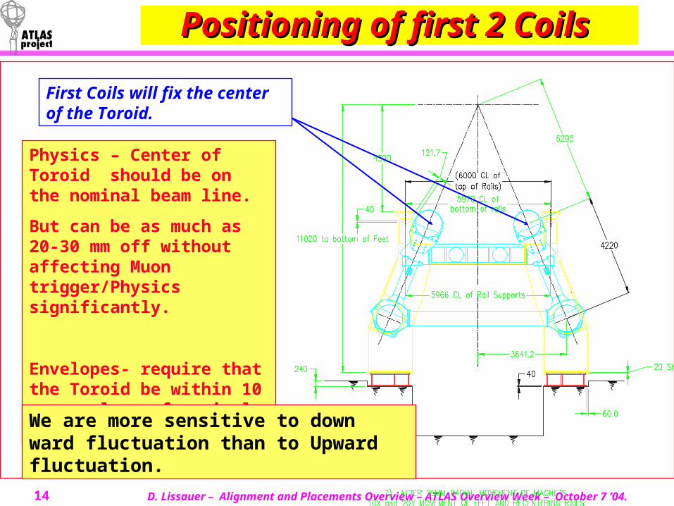
Positioning of first 2 Positioning of first 2 Coils Coils
First Coils will fix the center of the Toroid.
Physics – Center of Toroid should be on the nominal beam line.
But can be as much as 20-30 mm off without affecting Muon trigger/Physics significantly.
Envelopes- require that the Toroid be within 10 mm envelope of nominal position.
We are more sensitive to down ward fluctuation than to Upward fluctuation.
D. Lissauer – Alignment and Placements Overview – ATLAS Overview Week – October 7 ’04.15
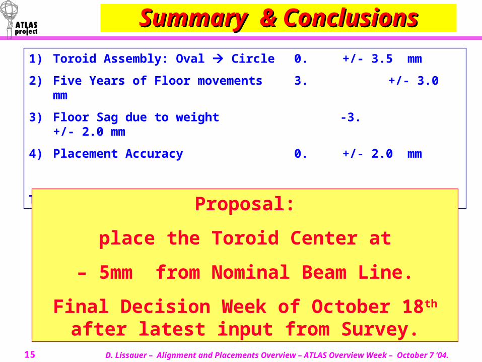
Summary & ConclusionsSummary & Conclusions
1) Toroid Assembly: Oval Circle 0. +/- 3.5 mm
2) Five Years of Floor movements 3. +/- 3.0 mm
3) Floor Sag due to weight -3. +/- 2.0 mm
4) Placement Accuracy 0. +/- 2.0 mm
Total: 0. +/- 10.5 mm
Proposal:
place the Toroid Center at
– 5mm from Nominal Beam Line.
Final Decision Week of October 18th after latest input from Survey.
D. Lissauer – Alignment and Placements Overview – ATLAS Overview Week – October 7 ’04.16
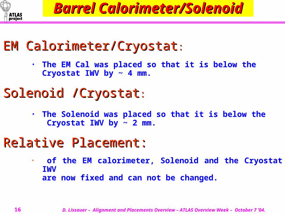
Barrel Barrel Calorimeter/SolenoidCalorimeter/Solenoid
EM Calorimeter/CryostatEM Calorimeter/Cryostat::• The EM Cal was placed so that it is below the
Cryostat IWV by ~ 4 mm.
Solenoid /CryostatSolenoid /Cryostat::
• The Solenoid was placed so that it is below the Cryostat IWV by ~ 2 mm.
Relative Placement:Relative Placement:• of the EM calorimeter, Solenoid and the Cryostat IWV
are now fixed and can not be changed.
D. Lissauer – Alignment and Placements Overview – ATLAS Overview Week – October 7 ’04.17
Barrel Barrel Calorimeter/SolenoidCalorimeter/Solenoid
Tile Calorimeter and Cryostat assembly is being done at Z=13. Tile Calorimeter and Cryostat assembly is being done at Z=13.
After LAr if placed on the Tile on the Truck the relative position After LAr if placed on the Tile on the Truck the relative position of the Tile/Cryostat IWV/Solenoid and EM position are fixed.of the Tile/Cryostat IWV/Solenoid and EM position are fixed.
The Tile Calorimeter/Cryostat assembly will than be moved to The Tile Calorimeter/Cryostat assembly will than be moved to Z=0.Z=0.
The Barrel Calorimeter can be adjusted as a unit to the The Barrel Calorimeter can be adjusted as a unit to the Nominal Beam line. Nominal Beam line.
D. Lissauer – Alignment and Placements Overview – ATLAS Overview Week – October 7 ’04.18
Barrel Barrel Calorimeter/SolenoidCalorimeter/Solenoid
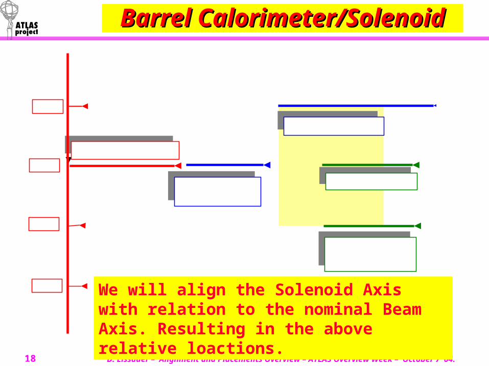
Nominal Beam Axis
0
2
-2
-4
Tile Calorimeter Axis
IWV Axis
Solenoid Axis
EM CalorimeterAxis
We will align the Solenoid Axis with relation to the nominal Beam Axis. Resulting in the above relative loactions.
D. Lissauer – Alignment and Placements Overview – ATLAS Overview Week – October 7 ’04.19
ID - InstallationID - InstallationTRT/SCT: TRT/SCT:
Are assembled on the Surface as a unit. The TRT and SCT Axis have to be co-linear. There is a small gap between the
TRT and SCT but it can not be reduced as it is part of the thermal shield and the construction tolerance.
Pixel Tube Installation:Pixel Tube Installation: Pixel Tube is installed first in the SCT/TRT module. On the Surface. Pixel Tube can be installed “off” center by as much as 2-3 mm.
SCT /TRT Axis is Collinear. No Possibility for adjustments of SCT relative to TRT.
Pixel Tube can be inserted off axis by as much as 2-3 mm.Once inserted they can not be adjusted.
D. Lissauer – Alignment and Placements Overview – ATLAS Overview Week – October 7 ’04.20
ID - InstallationID - InstallationSCT/TRT/Pixel Tube: SCT/TRT/Pixel Tube:
The SCT/TRT/Pixel Tube are installed as a unit. No relative adjustments of the individual components in possible in Situ. The Module is support are adjusted on the surface so that the SCT/TRT
axis will co inside with Barrel Cal IWV Axis. At this stage there is some adjustment in Situ possible – (Max +/- 4 mm)
but, ID aim will be to bring the Barrel IWV- TRT/SCT axis to co inside. This requirement that the TRT/SCT axis coincide comes from the very
tight space and the needed symmetry for the TRT/SCT Services.
The ID requires that the TRT/SCT axis co inside with the IWV axis dues to the ID Services needs.
ATLAS thus agrees that the TRT/SCT Axis will be placed2 mm off the nominal Beam Axis and off the Solenoid Axis.
D. Lissauer – Alignment and Placements Overview – ATLAS Overview Week – October 7 ’04.21
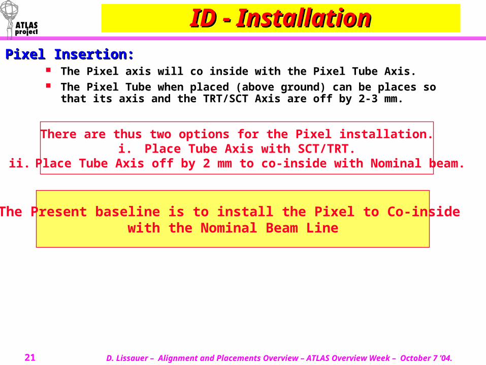
ID - InstallationID - InstallationPixel Insertion: Pixel Insertion:
The Pixel axis will co inside with the Pixel Tube Axis. The Pixel Tube when placed (above ground) can be places so that its axis and
the TRT/SCT Axis are off by 2-3 mm.
There are thus two options for the Pixel installation.i. Place Tube Axis with SCT/TRT.
ii. Place Tube Axis off by 2 mm to co-inside with Nominal beam.
The Present baseline is to install the Pixel to Co-inside with the Nominal Beam Line
D. Lissauer – Alignment and Placements Overview – ATLAS Overview Week – October 7 ’04.22
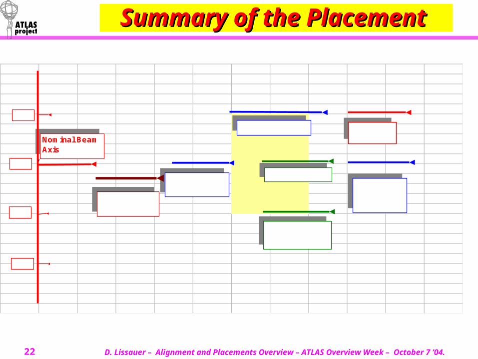
Summary of the Summary of the Placement Placement
Nominal Beam Axis
0
2
-2
-4
Tile Calorimeter Axis
IWV Axis
Solenoid Axis
EM CalorimeterAxis
Pixel Tube - PixelBeam Pipe
TRTSCT
Toroid Axis
D. Lissauer – Alignment and Placements Overview – ATLAS Overview Week – October 7 ’04.23
Barrel Muon SystemBarrel Muon System
The Muon Support structure:The Muon Support structure: Rail System. First adjustments above ground (Local Coordinate system) Final Adjustments in Situ before chambers are mounted. Each Tower points to the Intersection region.
Individual Alignment/Placements for each chamber Individual Alignment/Placements for each chamber assembly needs are being defined.assembly needs are being defined.
MDT’s & RPC’s subassembly done on the Surface. Once placed on the Rails no adjustments is possible.
Chamber Assembly Placement.Chamber Assembly Placement. The specification on chamber placement needs to be defined. Survey
Target position etc.
Alignment System. Alignment System.
D. Lissauer – Alignment and Placements Overview – ATLAS Overview Week – October 7 ’04.24
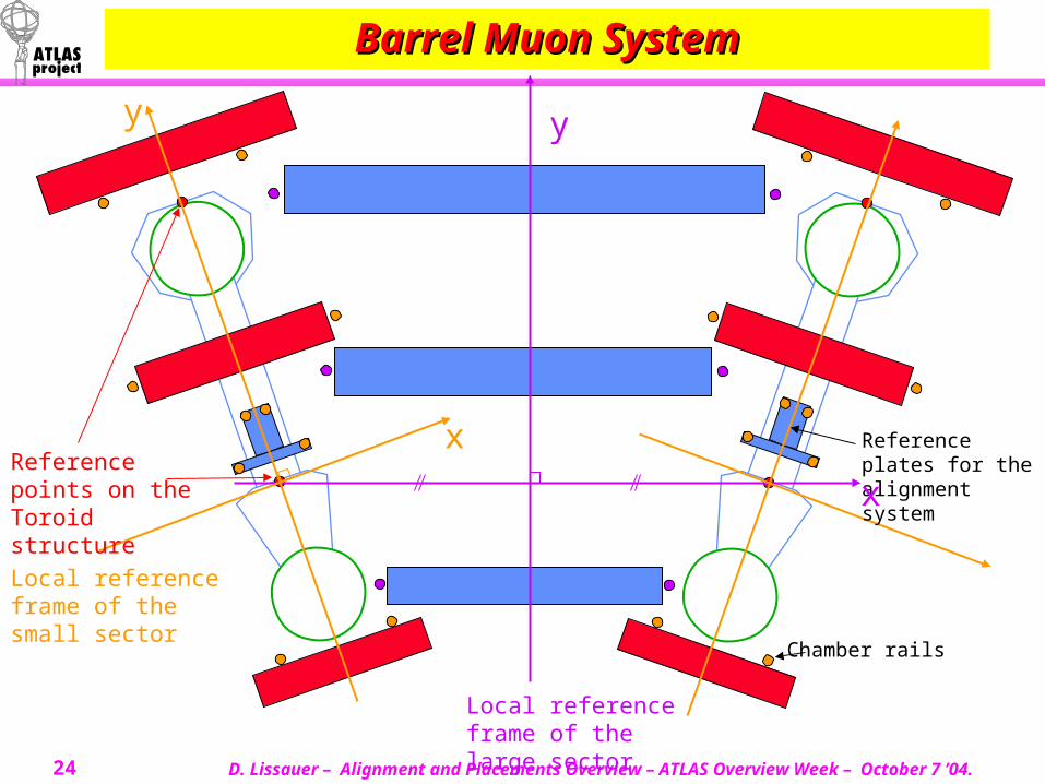
Barrel Muon SystemBarrel Muon System
Local reference frame of the large sector
Local reference frame of the small sector
Reference points on the Toroid structure
Chamber rails
Reference plates for the alignment system
y
x
y
x
D. Lissauer – Alignment and Placements Overview – ATLAS Overview Week – October 7 ’04.25
Conclusions:Conclusions:
Floor Monitoring systems are in place.Floor Monitoring systems are in place. ATLAS Placement has started. ATLAS has installed :Feet ATLAS Placement has started. ATLAS has installed :Feet
Rails, HS and HO structures. Rails, HS and HO structures. (Rails can still be readjusted )(Rails can still be readjusted )
This already has resulted in small change to detector This already has resulted in small change to detector envelopes and final placements. envelopes and final placements. (e.g. HO chambers moved by (e.g. HO chambers moved by 20 mm in Z.)20 mm in Z.)
Some Subassemblies on the Surface already completer: Some Subassemblies on the Surface already completer: Barrel EM/Solenoid/IWV completed, EC-C.Barrel EM/Solenoid/IWV completed, EC-C.
Agreement on Procedure and hierarchy for Barrel Agreement on Procedure and hierarchy for Barrel Calorimeter/Solenoid/ID placement.Calorimeter/Solenoid/ID placement.
Toroid Placement will start later this month. Toroid Placement will start later this month.
Need to follow and re-optimize placement of Need to follow and re-optimize placement of detectors continuously.detectors continuously.