asynchronous ascii event count status codes asynchronous ascii event count...asynchronous ascii...
TRANSCRIPT

IRIG STANDARD 215-12
TELECOMMUNICATIONS AND TIMING GROUP
ASYNCHRONOUS ASCII EVENT COUNT STATUS CODES
DISTRIBUTION A: APPROVED FOR PUBLIC RELEASE DISTRIBUTION IS UNLIMITED
WHITE SANDS MISSILE RANGE
REAGAN TEST SITE YUMA PROVING GROUND
DUGWAY PROVING GROUND ABERDEEN TEST CENTER
NAVAL AIR WARFARE CENTER WEAPONS DIVISION, PT. MUGU
NAVAL AIR WARFARE CENTER WEAPONS DIVISION, CHINA LAKE AVAL AIR WARFARE CENTER AIRCRAFT DIVISION, PATUXENT RIVER
NAVAL UNDERSEA WARFARE CENTER DIVISION, NEWPORT PACIFIC MISSILE RANGE FACILITY
NAVAL UNDERSEA WARFARE CENTER DIVISION, KEYPORT
30TH SPACE WING 45TH SPACE WING
AIR FORCE FLIGHT TEST CENTER AIR ARMAMENT CENTER
ARNOLD ENGINEERING DEVELOPMENT CENTER
NATIONAL AERONAUTICS AND SPACE ADMINISTRATION

This page intentionally left blank.

INTER-RANGE INSTRUMENTATION GROUP (IRIG) STANDARD 215-12
ASYNCHRONOUS ASCII EVENT COUNT STATUS CODES
MARCH 2012
Prepared by
TELECOMMUNICATIONS AND TIMING GROUP (TTG)
Published by
Secretariat Range Commanders Council
U.S. Army White Sands Missile Range, New Mexico 88002-5110

This page intentionally left blank.

Asynchronous ASCII Event Count Status Codes, IRIG Standard 215-12, March 2012
iii
TABLE OF CONTENTS
LIST OF FIGURES ....................................................................................................................... iv
LIST OF TABLES ......................................................................................................................... iv
PREFACE ........................................................................................................................................v
1. GENERAL DESCRIPTION OF THIS STANDARD .....................................................1
2. GENERAL DESCRIPTION OF FORMATS .................................................................1 2.1 IRIG CS-511z ..........................................................................................................1 2.2 IRIG CS-522z ..........................................................................................................4 2.3 IRIG CS-513z ..........................................................................................................6 2.4 IRIG CS-524z ..........................................................................................................8 2.5 IRIG CS-525z ........................................................................................................10
3. DETAILED GUIDANCE ................................................................................................14 3.2 Parity ......................................................................................................................14 3.3 Baud Rates .............................................................................................................14 3.4 IRIG CS Format Designation Description .............................................................14 3.5 Common IRIG CS Formats ...................................................................................15
4. NETWORK PACKET STRUCTURE ...........................................................................15 4.1 Ethernet Overhead .................................................................................................15 4.2 Multicast Packets ...................................................................................................15

Asynchronous ASCII Event Count Status Codes, IRIG Standard 215-12, March 2012
iv
LIST OF FIGURES
Figure 1. ASCII event count status format CS-511z. ..............................................................3 Figure 2. ASCII event count status format CS-522z. ..............................................................5 Figure 3. ASCII event count status format CS-513z. ..............................................................7 Figure 4. ASCII event count status format CS-524z. ..............................................................9 Figure 5. ASCII event count status format CS-525z. ............................................................12 Figure 6. CS525z Channel tagging illustration. ....................................................................13
LIST OF TABLES
Table 1. Tag Index Character Assignments .........................................................................11 Table 2. Standard IRIG CS Formats ....................................................................................15

Asynchronous ASCII Event Count Status Codes, IRIG Standard 215-12, March 2012
v
PREFACE
This Standard presents the results of work performed by the Telecommunications and Timing Group (TTG) under Task TT-53 for the Range Commanders Council (RCC). The TTG efforts produced a standard format for an N-channel asynchronous multiplex signal, suitable for N-channels of low speed data, including range count signals. The TTG has expanded work previously done on this document to include network-based transmission of count status. Many ranges utilize one or more "counts" (i.e. countdowns) to coordinate support activities in support of test range operations. Multiplexing of the multiple counts into one composite signal will lessen data transfer infrastructure requirements. The standardization of the multiple count data exchange formats shown herein is a large enhancement for range inter-operability. The use of the formats in this Standard will provide much needed compatibility at the ranges. For development of this Standard, the RCC acknowledges the excellent work by the many participating members on this effort. The RCC gives special recognition to:
Task Lead: Mr. William Trump
45 Space Wing Bldg 313, Rm 200 Patrick AFB, FL 32925 Phone: (321) 494-3131 E-mail: [email protected]
Please direct any questions to:
Secretariat, Range Commanders Council ATTN: TEDT-WS-RCC 100 Headquarters Avenue White Sands Missile Range, NM 88002-5110 Phone: (575) 678-1107 DSN 258-1107 E-mail: [email protected]

Asynchronous ASCII Event Count Status Codes, IRIG Standard 215-12, March 2012
vi
This page intentionally left blank.

Asynchronous ASCII Event Count Status Codes, IRIG Standard 215-12, March 2012
1
ASYNCHRONOUS ASCII EVENT COUNT (EC) STATUS CODES
1. General Description of This Standard
This standard describes five event count (EC) status formats to be used to transfer EC status over conventional asynchronous serial telecommunications circuits and Ethernet networks. The formats are American Standard Code for Information Interchange (ASCII) data formats. These formats provide EC status information suitable for most computer, dumb terminal, line printer, and remote visual displays. Precise EC status transfer is not an objective of this standard; therefore, there is no attempt to provide greater than 100 ms or 1second resolution for these formats. It should also be noted that even though the figures in the following sections appear to depict an exact bit alignment for the characters in each frame, the data is “asynchronous” and therefore may vary depending on inter-character delays. This standard provides systems engineers and equipment vendors with an Inter-range Instrumentation Group (IRIG) Standard for ASCII-formatted EC status transfer, which can be used in specifications for the procurement of equipment used on all United States test ranges and other military or civilian facilities.
2. General Description of Formats
An overview of the formats is given in the following paragraphs. See Figure 1 through Figure 6. 2.1 IRIG CS-511z
The IRIG CS-511z is a Time-of-Year format with 1-second resolution and frame length see Figure 1). The accuracy of this format at the receiver end is primarily dependent on the characteristics (fixed and variable transmission delays) of the communications circuits between the transmitting and receiving equipment. The ASCII expression for this format is:
<SOH>I<SP>±DDD<SP>HH:MM:SS<SP>#<CR><LF> Where:
<SOH> = start of header (0116). I = identification character -- space (2016) is default, any alpha or
numeric ASCII character. <SP> = space (2016). ± = the EC sign. DDD = the EC day. HH = the EC hour of the day. <:> = colon (3A16). MM = the EC minute of the hour. SS = the EC second of the minute. # = the EC status -- space (2016) is default, H (4816) if holding. <CR> = carriage return (0D16). <LF> = line feed (0A16).

Asynchronous ASCII Event Count Status Codes, IRIG Standard 215-12, March 2012
2
The IRIG CS-511z uses the first 20 characters of the 1-second frame. The remaining bits are idle (logic level = 1) for the remainder of the frame. The frame length is 1 second when using serial data, regardless of the baud rate. The identification character is an ASCII “space” character by default, although any alpha numeric ASCII character may be used. The definition or function of the identification character is left to the user. Suggested uses might be identification of a net or network, an event, a test number, or a user number.

Asynchronous ASCII Event Count Status Codes, IRIG Standard 215-12, March 2012
3
Figure 1. ASCII event count status format CS-511z.

Asynchronous ASCII Event Count Status Codes, IRIG Standard 215-12, March 2012
4
2.2 IRIG CS-522z
The IRIG CS-522z is a Time-of-Year format with 100-millisecond resolution and frame length (see Figure 2). The accuracy of this format at the receiver end is primarily dependent on the characteristics (fixed and variable transmission delays) of the communications circuits between the transmitting and receiving equipment. The ASCII expression for this format is
<SOH>I<SP>±DDD<SP>HH:MM:SS.S<SP>#<CR><LF> Where:
<SOH> = start of header (0116). I = identification character -- space (2016) is default, any alpha or
numeric ASCII character. <SP> = space (2016). ± = the EC sign. DDD = the EC day. HH = the EC hour of the day. <:> = colon (3A16). MM = the EC minute of the hour. SS.S = the EC second and tenth of second of the minute
{period “.” = (2E16)}. # = the EC status -- space (2016) is default, H (4816) if holding. <CR> = carriage return (0D16). <LF> = line feed (0A16).
The IRIG CS-522z uses the first 22 characters of the 100 ms frame. The remaining bits are idle (logic level = 1) for the remainder of the frame. The frame length is 100 milliseconds when using serial data, regardless of the baud rate. The identification character is an ASCII “space” character by default, although any alpha numeric ASCII character may be used. The definition or function of the identification character is left to the user. Suggested uses might be identification of a net or network, an event, a test number, or a user number.

Asynchronous ASCII Event Count Status Codes, IRIG Standard 215-12-March 2012
5
Figure 2. ASCII event count status format CS-522z.

Asynchronous ASCII Event Count Status Codes, IRIG Standard 215-12, March 2012
6
2.3 IRIG CS-513z
The IRIG CS-513z is a Time-of-Year format with 1-second resolution and frame length (see Figure 3). In addition to the EC status, this format has information regarding the predicted time of launch or the actual time of launch if launch has occurred. The accuracy of this format at the receiver end is primarily dependent on the characteristics (fixed and variable transmission delays) of the communications circuits between the transmitting and receiving equipment. The ASCII expression for this format is:
<SOH>I<SP>±DDD<SP>HH:MM:SS<SP>#<SP>ddd<SP>hh:mm:ss.sss<SP>&<CR><LF>
Where:
<SOH> = start of header (0116). I = identification character -- space (2016) is default, any alpha or
numeric ASCII character. <SP> = space (2016). ± = the EC sign. DDD = the EC day. HH = the EC hour of the day. <:> = colon (3A16). MM = the EC minute of the hour. SS = the EC second of the minute. # = the EC status -- space (2016) is default, H (4816) if holding. ddd = predicted/actual launch day. hh = predicted/actual launch hour of the day. mm = predicted/actual launch minute of the hour. ss.sss = predicted/actual launch second and milliseconds of the minute
{period “.” = (2E16)}. & = launch time information -- P(5016) predicted, A(4116) actual. <CR> = carriage return (0D16). <LF> = line feed (0A16).
The IRIG CS-513z uses the first 39 characters of the 1-second frame. The remaining bits are idle (logic level = 1) for the remainder of the frame. The frame length is 1 second when using serial data, regardless of the baud rate. The identification character is an ASCII “space” character by default, although any alpha numeric ASCII character may be used. The definition or function of the identification character is left to the user. Suggested uses might be identification of a net or network, an event, a test number, or a user number.

Asynchronous ASCII Event Count Status Codes, IRIG Standard 215-12, March 2012
7
Figure 3. ASCII event count status format CS-513z.

Asynchronous ASCII Event Count Status Codes, IRIG Standard 215-12, March 2012
8
2.4 IRIG CS-524z
The IRIG CS-524z is a Time-of-Year format with 100-millisecond resolution and frame length (see Figure 4). In addition to the EC status, this format has information regarding the predicted time of launch or the actual time of launch if launch has occurred. The accuracy of this format at the receiver end is primarily dependent on the characteristics (fixed and variable transmission delays) of the communications circuits between the transmitting and receiving equipment. The ASCII expression for this format is:
<SOH>I<SP>±DDD<SP>HH:MM:SS.S<SP>#<SP>ddd<SP>hh:mm:ss.sss<SP>&<CR><LF>
Where:
<SOH> = start of header (0116). I = identification character -- space (2016) is default, any alpha or
numeric ASCII character. <SP> = space (2016). ± = the EC sign. DDD = the EC day. HH = the EC hour of the day. <:> = colon (3A16). SS.S = the EC second and tenth of second of the minute
{period “.” = (2E16)}. # = the EC status -- space (2016) is default, H (4816) if holding. ddd = predicted/actual launch day. hh = predicted/actual launch hour of the day. mm = predicted/actual launch minute of the hour. ss.sss = predicted/actual launch second and milliseconds of the minute. & = launch time information -- P(5016) predicted, A(4116) actual. <CR> = carriage return (0D16). <LF> = line feed (0A16).
The IRIG CS-524z uses the first 41 characters of the 100-millisecond frame. The remaining bits are idle (logic level = 1) for the remainder of the frame. The frame length is 100 milliseconds when using serial data, regardless of the baud rate. The identification character is an ASCII "space" character by default, although any alpha numeric ASCII character may be used. The definition or function of the identification character is left to the user. Suggested uses might be identification of a net or network, an event, a test number, or a user number.

Asynchronous ASCII Event Count Status Codes, IRIG Standard 215-12, March 2012
9
Figure 4. ASCII event count status format CS-524z.

Asynchronous ASCII Event Count Status Codes, IRIG Standard 215-12, March 2012
10
2.5 IRIG CS-525z
The IRIG CS-525z is a multiplexed, eight-channel version of the IRIG CS-524z format (described in paragraph 2.4) transmitted at 38,400 baud when using serial data. The eight channels are asynchronous, relative to each other. Each 100 ms frame of data contains 382 ASCII characters (as described in paragraph 3.1). This format also allows each of the eight channels to have an associated 16 character “Tag” transmitted with the count data, which can be used for an Operation Number, or any label (L Count, T Count, etc.) for the channel. Figure 5 illustrates the data frame. The start of the CS-525z data frame is identified by a “Frame Marker” character, which is a hexadecimal 1C (1C16). The second character in the data frame is the Index character to identify the channel and location of the tag data. The following four characters contain Tag characters. The next eight characters are the first available IRIG CS-524z characters from each of the eight channels of data. The following eight characters are the second available characters from each of the eight channels, and the sequence is repeated until 47 characters are provided for each of the eight channels. The remaining bits will be idle until the end of the 100 ms frame.
The first available IRIG CS-524z characters can be from anywhere within its data stream (i.e. may not be the Start of Header (SOH) character). However, receiving equipment will not begin decoding the channel data until the SOH (0116) is received. When no data is available for a channel, a substitute character (1A16) is sent.
The Tag is sent within the count data stream in four-byte increments per 100 ms frame. It takes 32 data frames (3.2 seconds) to load the labels for all eight channels. An Index Character is transmitted with each 100 ms data frame to identify the destination of the four character tag data in each frame. The Index character repeatedly increments, logically, from 1 to 32 (2116 to 4016) to fill the 128 bytes of label data every 3.2 seconds. See Table 1 for Index character assignments. When no Tag character is assigned, the Index character is 5516. Figure 6 illustrates how the Tag data is transmitted with the data frames.
To avoid conflict with special control characters, the Index character starts at 2116 (the ASCII “!”), and increments through 4016 (the ASCII “@”). Subtracting a constant (2016) from the Index character will return a number from 0116 to 2016. In addition, the data contained in the Tag should only include characters from “space” (2016) to “~” (7E16).

Asynchronous ASCII Event Count Status Codes, IRIG Standard 215-12, March 2012
11
TABLE 1. TAG INDEX CHARACTER ASSIGNMENTS
Index Character Channel Tag
Character Index
Character Channel Tag Character
2116 1 1 – 4 3116 5 1 – 4
2216 1 5 – 8 3216 5 5 – 8
2316 1 9 – 12 3316 5 9 – 12
2416 1 13 – 16 3416 5 13 – 16
2516 2 1 – 4 3516 6 1 – 4
2616 2 5 – 8 3616 6 5 – 8
2716 2 9 – 12 3716 6 9 – 12
2816 2 13 – 16 3816 6 13 – 16
2916 3 1 – 4 3916 7 1 – 4
2A16 3 5 – 8 3A16 7 5 – 8
2B16 3 9 – 12 3B16 7 9 – 12
2C16 3 13 – 16 3C16 7 13 – 16
2D16 4 1 – 4 3D16 8 1 – 4
2E16 4 5 – 8 3E16 8 5 – 8
2F16 4 9 – 12 3F16 8 9 – 12
3016 4 13 – 16 4016 8 13 – 16

Asynchronous ASCII Event Count Status Codes, IRIG Standard 215-12, March 2012
12
TAG DATA FIRST SET OF COUNT DATA (1 BYTE PER CHANNEL) START OF
FRAME
IC16 TAG
INDEX. TAG
CHARACTER TAG
CHARACTER TAG
CHARACTER TAG
CHARACTER CH 1BYTE 1 CH 2BYTE 1 CH 3BYTE 1 CH 4BYTE 1 CH 5BYTE 1 CH 6BYTE 1 CH 7BYTE 1 CH 8BYTE 1 • • •
BYTE 1 BYTE 2 BYTE 3 BYTE 4 BYTE 5 BYTE 6 BYTE 7 BYTE 8 BYTE 9 BYTE 10 BYTE 11 BYTE 12 BYTE 13 BYTE 14
SECOND SET OF COUNT DATA
CH 1BYTE 2 CH 2BYTE 2 CH 3BYTE 2 CH 4BYTE 2 CH 5BYTE 2 CH 6BYTE 2 CH 7BYTE 2 CH 8BYTE 2 CH 1BYTE 3 • • •
BYTE 15 BYTE 16 BYTE 17 BYTE 18 BYTE 19 BYTE 20 BYTE 21 BYTE 22 BYTE 23
FORTY SEVENTH (FINAL) SET OF COUNT DATA END OF FRAME
• • • CH 1BYTE 47 CH 2BYTE 47 CH 3BYTE 47 CH 4BYTE 47 CH 5BYTE 47 CH 6BYTE 47 CH 7BYTE 47 CH 8BYTE 47
BYTE 375 BYTE 376 BYTE 377 BYTE 378 BYTE 379 BYTE 380 BYTE 381 BYTE 382
Notes: a. In each 100 ms frame, 382 bytes of data are transmitted and remaining time is idle. b. Byte 1 is the frame marker, IC16. c. Byte 2 is the Tag Index, 2116 - 4016 (see Table 1 and Figure 6). d. Byte 2 is 5516 when no tag data is available. e Bytes 3 - 6 are tag data (see Figure 6). f. Bytes 7 - 382 are 8 channels of CS-524z count data. g. CS-524z data may begin (SOH) at any point in the data stream (asynchronously) h. When no count data is available, a 1A16 is sent. i. Data stream is sent with odd parity.
Figure 5. ASCII event count status format CS-525z.

Asynchronous ASCII Event Count Status Codes, IRIG Standard 215-12, March 2012
13
START OF FRAME
INDEX CHARACTER
TAG DATA
COUNT DATA
FRAME 1 1C16 2116 CH 1 TAG CHAR 1
CH 1 TAG CHAR 2
CH 1 TAG CHAR 3
CH 1 TAG CHAR 4 CH 1BYTE 1 ● ● ● CH 8BYTE 47
BYTE 1 BYTE 2 BYTE 3 BYTE 4 BYTE 5 BYTE 6 BYTE 7 BYTE 382
FRAME 2 1C16 2216 CH 1 TAG CHAR 5
CH 1 TAG CHAR 6
CH 1 TAG CHAR 7
CH 1 TAG CHAR 8 CH 1BYTE 1 ● ● ● CH 8BYTE 47
BYTE 1 BYTE 2 BYTE 3 BYTE 4 BYTE 5 BYTE 6 BYTE 7 BYTE 382
FRAME 3 1C16 2316 CH 1 TAG CHAR 9
CH 1 TAG CHAR 10
CH 1 TAG CHAR 11
CH 1 TAG CHAR 12 CH 1BYTE 1 ● ● ● CH 8BYTE 47
BYTE 1 BYTE 2 BYTE 3 BYTE 4 BYTE 5 BYTE 6 BYTE 7 BYTE 382
FRAME 4 1C16 2416 CH 1 TAG CHAR 13
CH 1 TAG CHAR 14
CH 1 TAG CHAR 15
CH 1 TAG CHAR 16 CH 1BYTE 1 ● ● ● CH 8BYTE 47
BYTE 1 BYTE 2 BYTE 3 BYTE 4 BYTE 5 BYTE 6 BYTE 7 BYTE 382
FRAME 5 1C16 2516 CH 2 TAG CHAR 1
CH 2 TAG CHAR 2
CH 2 TAG CHAR 3
CH 2 TAG CHAR 4 CH 1BYTE 1 ● ● ● CH 8BYTE 47
BYTE 1 BYTE 2 BYTE 3 BYTE 4 BYTE 5 BYTE 6 BYTE 7 BYTE 382 ● ● ●
FRAME 32 1C16 4016 CH 8 TAG CHAR 13
CH 8 TAG CHAR 14
CH 8 TAG CHAR 15
CH 8 TAG CHAR 16 CH 1BYTE 1 ● ● ● CH 8BYTE 47
BYTE 1 BYTE 2 BYTE 3 BYTE 4 BYTE 5 BYTE 6 BYTE 7 BYTE 382
Figure 6. CS525z Channel tagging illustration.
Asynchronous ASCII Event Count Status Codes, IRIG Standard 215-12, March 2012
14
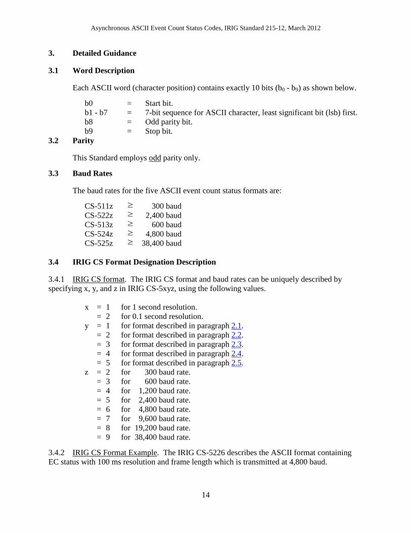
3. Detailed Guidance
3.1 Word Description
Each ASCII word (character position) contains exactly 10 bits (b0 - b9) as shown below.
b0 = Start bit. b1 - b7 = 7-bit sequence for ASCII character, least significant bit (lsb) first. b8 = Odd parity bit. b9 = Stop bit.
3.2 Parity
This Standard employs odd parity only. 3.3 Baud Rates
The baud rates for the five ASCII event count status formats are:
CS-511z ≥ 300 baud CS-522z ≥ 2,400 baud CS-513z ≥ 600 baud CS-524z ≥ 4,800 baud CS-525z ≥ 38,400 baud
3.4 IRIG CS Format Designation Description
3.4.1 IRIG CS format. The IRIG CS format and baud rates can be uniquely described by specifying x, y, and z in IRIG CS-5xyz, using the following values.
x = 1 for 1 second resolution. = 2 for 0.1 second resolution. y = 1 for format described in paragraph 2.1. = 2 for format described in paragraph 2.2. = 3 for format described in paragraph 2.3. = 4 for format described in paragraph 2.4. = 5 for format described in paragraph 2.5. z = 2 for 300 baud rate. = 3 for 600 baud rate. = 4 for 1,200 baud rate. = 5 for 2,400 baud rate. = 6 for 4,800 baud rate. = 7 for 9,600 baud rate. = 8 for 19,200 baud rate. = 9 for 38,400 baud rate.
3.4.2 IRIG CS Format Example. The IRIG CS-5226 describes the ASCII format containing EC status with 100 ms resolution and frame length which is transmitted at 4,800 baud.

Asynchronous ASCII Event Count Status Codes, IRIG Standard 215-12, March 2012
15
3.5 Common IRIG CS Formats
Table-2 contains a list of common formats.
TABLE 2. COMMON IRIG CS FORMATS
IRIG CS-5112 IRIG CS-5225 IRIG CS-5133 IRIG CS-5246 IRIG CS-5259
IRIG CS-511N IRIG CS-522N IRIG CS-513N IRIG CS-524N IRIG CS-525N 4. Network Packet Structure
4.1 Ethernet Overhead
The Ethernet overhead consists of header and trailer information that is added to the Communications over Internet Protocol (CoIP) Layer 6 Payload. The contents of the payload are described in the individual CS5 format descriptions (i.e. CS-524N contains 41 characters in the payload and is transmitted 10 times per second).
4.2 Multicast Packets
4.1.1 Internet Protocol (IP)/User Datagram Protocol (UDP). The IP/UDP multicast supports communications from one transmitter to multiple receivers over an IP network. Support for a large number of receivers is inherent, as the identity of the receiver and the number of receivers is not required. Multicast is bandwidth efficient because the transmitter has to send the packet only once. The packets are replicated by the downstream nodes as required to support delivery to all receivers. 4.1.2 Multicast Group Addresses. Multicast packets use special types of IP addresses that identifies to the network that the packet contains multicast traffic. These IP addresses are referred to as multicast group addresses. Multicast addresses are identified by the pattern "1110" in the first 4 bits, which corresponds to a first octet of 224 to 239. The full range of multicast addresses is from 224.0.0.0 to 239.255.255.255. 4.2.3 Internet Group Management Protocol. At the network ingress, the network transmit stream will be constructed with the multicast group address as the destination address. If a node wants to receive traffic from a particular multicast group, it must inform the network. The receiver "joins" the multicast group. Once the receiver has joined a particular multicast group, the network equipment in the path forwards the packets for that multicast group to the receiver. If no receivers have joined a multicast group, the network equipment will not forward these packets. In this fashion, multicast traffic only consumes network bandwidth when a receiver requests the traffic. The protocol used by receivers to join a multicast group is called the Internet Group Management Protocol (GMP).

Asynchronous ASCII Event Count Status Codes, IRIG Standard 215-12, March 2012
16
4.2.4 Additional Protocols. An additional set of protocols, Session Announcement Protocol (SAP) and Session Description Protocol (SDP), allow multicast senders to communicate the characteristics of their multicast streams to potential receivers. The receivers monitor the SAP packets to identify potential streams that they may want to decode. The SAP listening applications can listen to the well-known SAP multicast addresses and construct a guide of all advertised multicast sessions. The SAP uses SDP as the format of the session descriptions.
**** NOTHING FOLLOWS ****